Loading ...
Loading ...
Loading ...
39
Instructions for the installer
12.3 Burner and nozzle characteristics table
Burner
Rated heating
capacity
(kW)
LPG GAS - G30/G31 28-30/37 mbar
Nozzle
diameter
(1/100 mm)
Reduced
capacity
(W)
Capacity
(g/h G30)
Capacity
(g/h G31)
Auxiliary 1.05 50 400 76 75
Semi-rapid 1.8 65 500 131 129
Rapid 3.0 85 800 218 214
Ultra-rapid 3.5 94 1600 255 250
Burner
Rated heating
capacity
(kW)
NATURAL GAS - G20 20 mbar
Nozzle
diameter
(1/100 mm)
Prechamber
(printed on
nozzle)
Reduced capacity
(W)
Auxiliary 1.05 72 (X) 400
Semi-rapid 1.8 97 (Z) 500
Rapid 3.0 115 (Y) 800
Ultra-rapid 3.5 140 (-6) 1600
12.4 Final operations
After replacing the nozzles, reposition the flame-spreader crowns, the burner caps and the pan stands.
Following adjustment to a gas other than the one originally set in the factory, replace the gas setting
label fixed to the appliance with the one corresponding to the new gas. The label is inserted inside the
nozzle pack (where present).
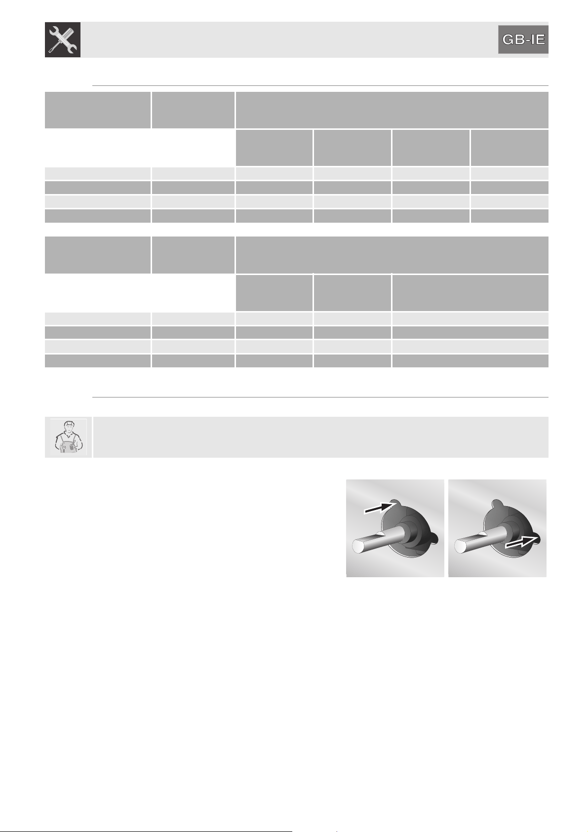
12.4.1Adjusting the hob burner minimum setting for city or natural gas
Light the burner and turn it to the minimum position.
Extract the gas tap knob and turn the adjustment screw
next to the tap rod (depending on the model) until the
correct minimum flame is achieved.
Refit the knob and verify that the burner flame is stable
(when turning the knob rapidly from the maximum to the
minimum position the flame must not go out). Repeat the
operation on all the gas taps.
12.4.2Adjusting the hob burner minimum setting for LPG
In order to adjust the minimum setting with LPG, the screw at the side of the tap rod must be tightened
clockwise all the way.
Loading ...
Loading ...
Loading ...