Loading ...
Loading ...
Loading ...

Page 8
Models D49M30SB • D49M36SB • D49M48SB
FLEXIBLE
BLOWER
M
ELECTRICAL PANEL
WIRING
BOX
BLACK (HIGH 4)
WHITE (NEUTRAL)
BLUE (LOW 1)
GRAY (MED 2)
GROUND SCREW
ORANGE (MED-HIGH)
BLACK
WHITE
BLUE
RED
ORANGE
GREEN
LOWER
RECEPTACLE
ELECTRICAL
PANEL CABLE
CABINET BOTTOM
WIRING
BOX
COVER
INSTALL ELECTRICAL WIRING
1. Mount a standard wiring box, with 3-pronged receptacle, within
reach of the downdraft's power cord.
2. Run appropriate power cable and connect it to receptacle.
CAUTION: All electrical wiring should be done
by a qualified person(s) in accordance with all
applicable codes and standards.
Installations using FLEX BLOWER only:
3. Remove WIRING BOX COVER and connect blower wires to
wires in wiring box. Black to black, white to white, blue to blue,
orange to orange, gray to red, and green to ground screw.
1. Mount a standard wiring box, with 3-pronged receptacle, within
reach of the downdraft's power cord.
2. Run appropriate power cable into cabinet and connect it to
electrical box and receptacle.
3. These exterior or in-line blower can be used:
Models EB6, EB9, EB12, or EB15 - Exterior
Models ILB3, ILB6, ILB9, or ILB11 - In-Line
120 VAC • 60 Hz • 6.0 A (max.)
4. Run 2-wire plus ground power cable from the exterior or in-line
blower to wiring box on adaptor plate. Remove WIRING BOX
COVER.
5. Connect blower wires to power cable from exterior or in-line
blower. Black to black, white to white, and green to ground
screw.
CAUTION: All electrical wiring should be done
by a qualified person(s) in accordance with all
applicable codes and standards.
Installations using REMOTE BLOWER only:
REMOTE
BLOWER
M
ELECTRICAL PANEL
WIRING
BOX
BLACK
WHITE (NEUTRAL)
GROUND SCREW
4. Replace wiring box cover.
5 Plug ELECTRICAL PANEL CABLE into LOWER RECEPTACLE
as shown.
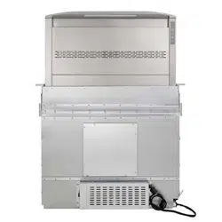
6. Plug the downdraft's power cord into the outlet. Make sure that
the power cord is routed away from the heat generated by the
cooktop.
6. Replace wiring box cover.
7. Plug ELECTRICAL PANEL CABLE into LOWER RECEPTACLE
as shown.
8. Plug the downdraft's power cord into the outlet. Make sure that
the power cord is routed away from the heat generated by the
cooktop.
LOWER
RECEPTACLE
ELECTRICAL
PANEL CABLE
CABINET BOTTOM
Loading ...
Loading ...
Loading ...
