Loading ...
Installation of the Wall Control - cavity wall without outlet box
1) DetermineasuitableplacetoinstalltheWallControl(awayfromsourcesofheat,sunlight,orventilation,and
between4and6feetfromtheoor).Donotinstallnearcooleropening.
2) Usingthemountingplateasaguide,markthelocationofthetwomountingpointsandtheterminalopening
fortheconnectionterminal.
3) Makeaholeinthewalljustlargeenoughtoaccommodatetheconnectionterminalandassociatedwiring.
4) Routeaninsulatedthree-conductorthermostatcable(orsimilarlowvoltagecable)fromtheApplianceControl
Boxthroughthehole,leavingaboutsixinchesprotruding.
5) Routethewiringthroughtheopeninginthewallcontrolmountingplate.Usingwallanchors,screwthe
mountingplatetothewall.
6) Connectthewirestotheterminalsasperthewiringconnectiondiagrambelow.Thesesamewirecolorsmatch
thoseindicatedonthecontrolbox.
7) Plugtheconnectionterminalintothebackofthewallcontrol.Placethetabsonthemountingplateintotheholesinthetopofthe
thermostatandrotatetheWallControluntilitsnapsontothemountingplate.Youmayusetheprovidedscrewtosecureitinplace.
FLO
FHI
Fcom
Link
L1
N
NLink
Pp
Pcom
Pe
Pecom
Fan/Pump 120V
Fan/Pump 240V
Fan 240V
Pump 120V
Fan 120V
Pump 240V
Fan Low
Fan
Power Supply
Pump Purge
Fan High
Fan Common
Pump Power
Pump Common
Purge Power
Purge Common
Not
Used
Not
Used
N
N NL2
L1
L2
L1 L1 L1
L2
Ground Connections*
*Note: Use the provided wire nut to connect all ground connections for power
supply, fan, pump, purge pump and cooler cabinet.
Warning: Use jumper between Link and NLink only when Fan and Pump
voltages are the same.
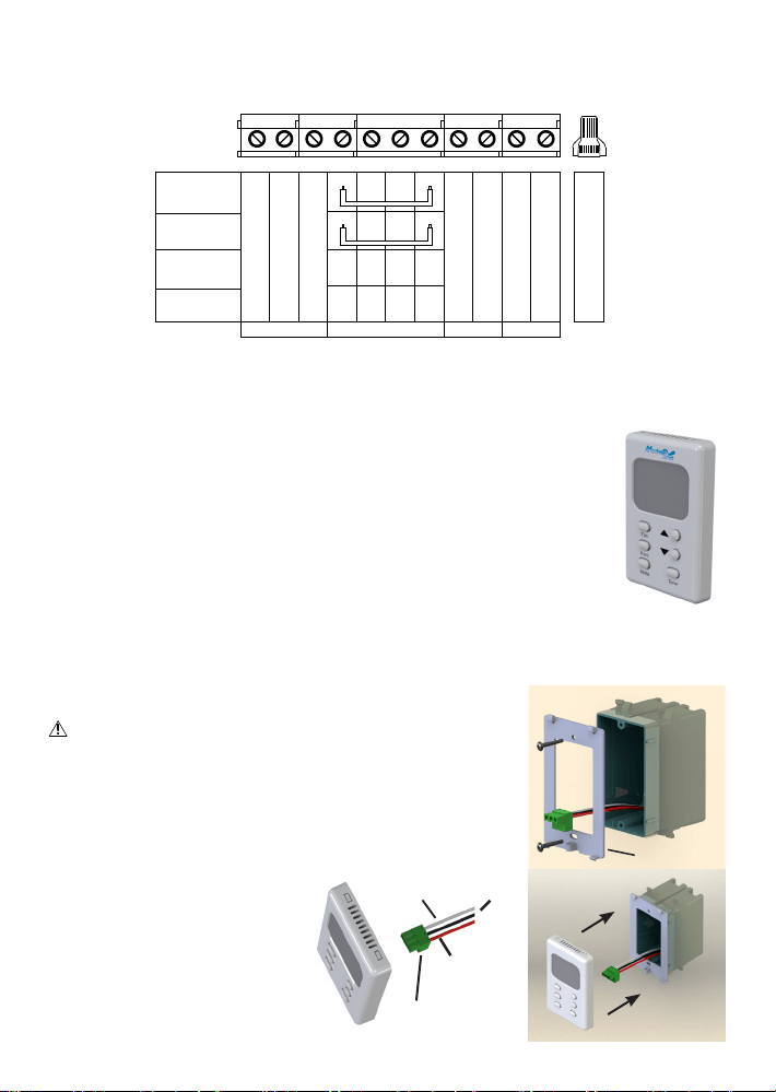
Wiring Connections - Use Copper Conductors
Wiring Connections in Appliance Control Box
ConnectionTerminal
Red
Black
White
MountingPlate
Installation of the Wall Control - using an existing wall-mounted outlet box
CAUTION: Only use a single outlet box and do not share wiring with any other
equipment.
1) Routeaninsulatedthree-conductorthermostatcable(orsimilarlowvoltagecable)fromthe
ApplianceControlBoxtotheoutletbox,leavingaboutsixinchesprotruding.
2) Routethewiringthroughtheopeninginthewallcontrolmountingplate.Screwthemount-
ingplatetotheoutletbox.
3) Connectthewirestotheterminalsasperthewiringconnectiondiagrambelow.These
samewirecolorsmatchthoseindicatedonthe
controlbox.
4) Plugtheconnectionterminalintotheback
ofthewallcontrol.Placethetabsonthe
mountingplateintotheholesinthetopofthe
thermostatandrotatetheWallControluntilit
snapsontothemountingplate.Youmayuse
theprovidedscrewtosecureitinplace.
Loading ...
Loading ...