Loading ...
Loading ...
Loading ...
30
MO30 STA NE
3. Secure latch hook (with two (2) mounting screws) to
oven flange.
4. Make sure that the monitor switch is operating
properly
and check continuity of the monitor circuit. Refer to chapter
"Test Procedure" and Adjustment procedure.
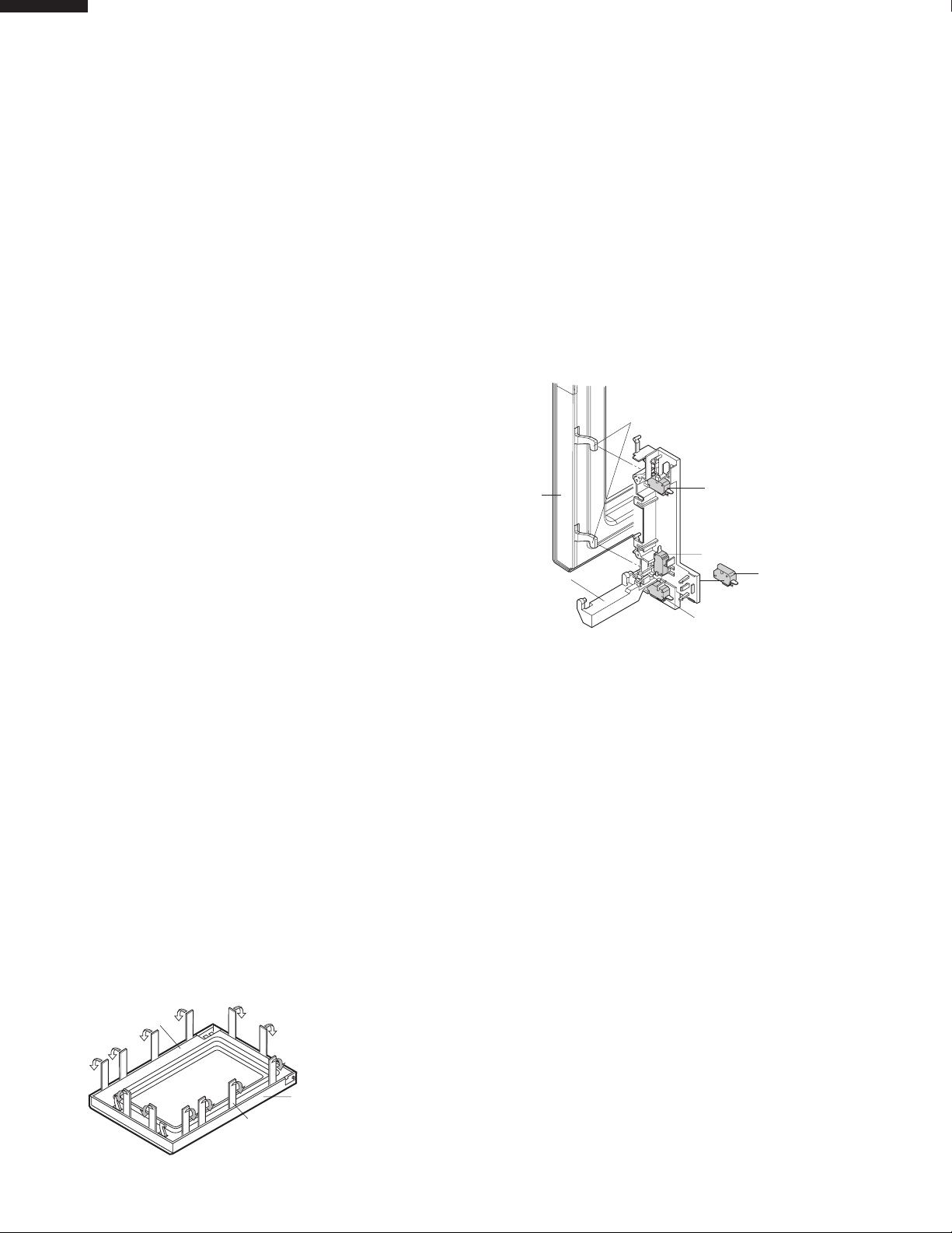
DOOR SENSING SWITCH/PRIMARY SWITCH/SECONDARY SWITCH AND MONITOR SWITCH ADJUSTMENT
1. Disconnect the power supply cord, and then remove
outer case.
2. Open the door and block it open.
3. Discharge high voltage capacitor.
If the door sensing switch, primary switch, secondary switch
and monitor switch do not operate properly due to a misad-
justment, the following adjustment should be made.
4. Loosen the two (2) screws holding latch hook to the oven
cavity front flange.
5. With door closed, adjust latch hook by moving it back
and
forth, and up and down. In and out play of the door
allowed by the upper and lower position of the latch
hook should be less than 0.5mm. The vertical position
of the latch hook should be adjusted so that the door
sensing switch, primary switch and secondary switch are
activated with the door closed. The horizontal position of
the latch hook should be adjusted so that the plunger of
the monitor switch is pressed with the door closed.
6. Secure the screws with washers firmly.
7. Check the operation of all switches. If each switch has
not activated with the door closed, loosen screw and
adjust the latch hook position.
After adjustment, check the following.
1. In and out play of door remains less than 0.5mm when
in the latched position. First check upper position of latch
hook, pushing and pulling upper portion of door toward
the oven face. Then check lower portion of the latch
Figure C-3. Latch Switch Adjustments
hook, pushing and pulling upper portion of door toward
the oven face. Both results (play in the door) should be
less than 0.5mm.
2. The door sensing switch, primary switch and secondary
switch interrupt the circuit before the door can be
opened.
3. Monitor switch contacts close when door is opened.
4. Re-install outer case and check for microwave leakage
around door with an approved microwave survey meter.
DOOR REPLACEMENT
REMOVAL
1. Disconnect the power supply cord.
2. Push the open button and open the door.
3. Remove door stopper, then release two (2) pins of door
panel from two (2) holes of upper and lower oven hinges
by lifting up.
4. Insert a putty knife (thickness of about 0.5mm) into the
gap between the choke cover and door frame as shown
in Figure C-4 to free engaging parts.
5. Pry the choke cover by inserting a putty knife as shown
Figure C-4.
6. Release choke cover from door panel.
7. Now choke cover is free.
Figure C-4. Door Disassembly
8. Release the door panel from twelve (12) tabs of door
frame.
9. Remove the door panel from the door frame.
10. Now, door panel is free.
11. Slide latch head upward and remove it from door frame
with releasing latch spring from door frame and latch
head.
12. Now, latch head and latch spring are free.
13. Remove door screen from door frame
14. Now, door frame is free.
RE-INSTALL
1. Re-install door screen to door frame.
2. Re-install the latch spring to the latch head. Re-install
the latch spring to the door frame. Re-install latch head
to door frame.
3. Re-install door panel to door frame by fitting twelve (12)
tabs of door frame to twelve (12) holes of door panel.
4. Put sealer film on door panel. Refer to “Sealer Film” about
how to handle new one.
5. Catch two (2) pins of door panel on two (2) hole of upper
and lower oven hinges and door stopper.
Door Sensing
Switch
Monitor Switch
Switch Lever
Secondary
Switch
Latch Heads
Door
Primary
Switch
Choke Cover
Door Frame
Putty Knife
Loading ...
Loading ...
Loading ...