Installation and Operation Instructions
ELECTRIC FIREPLACE
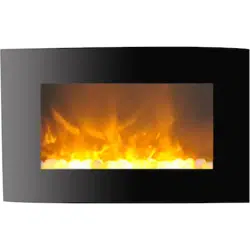
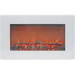
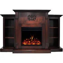
CAM35WMEF
Important Safety Instructions
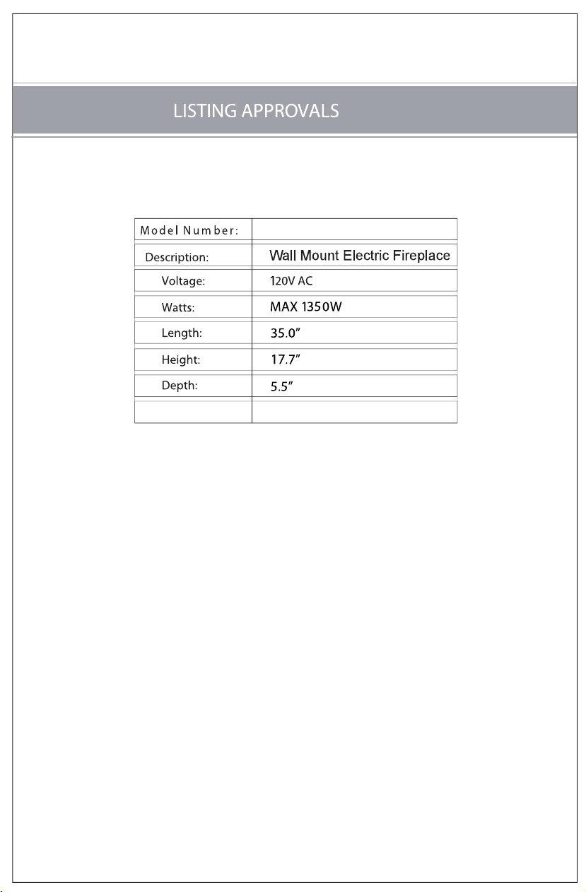
Listing Approvals
Product Dimensions
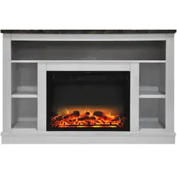
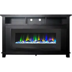
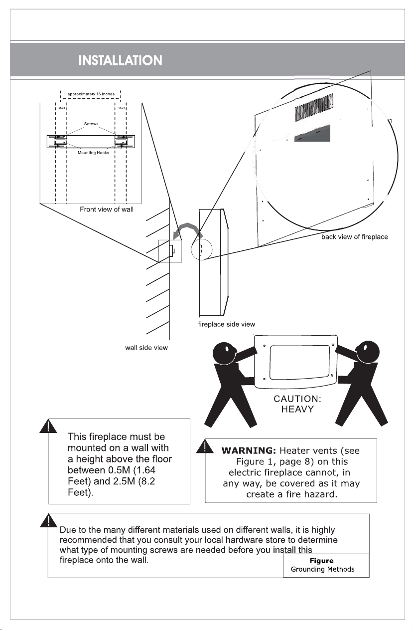
Locating Fireplace
Unpacking and Testing Fireplace
Grounding Instructions
Installation
Finishing Ckecklist
Operating Instructions
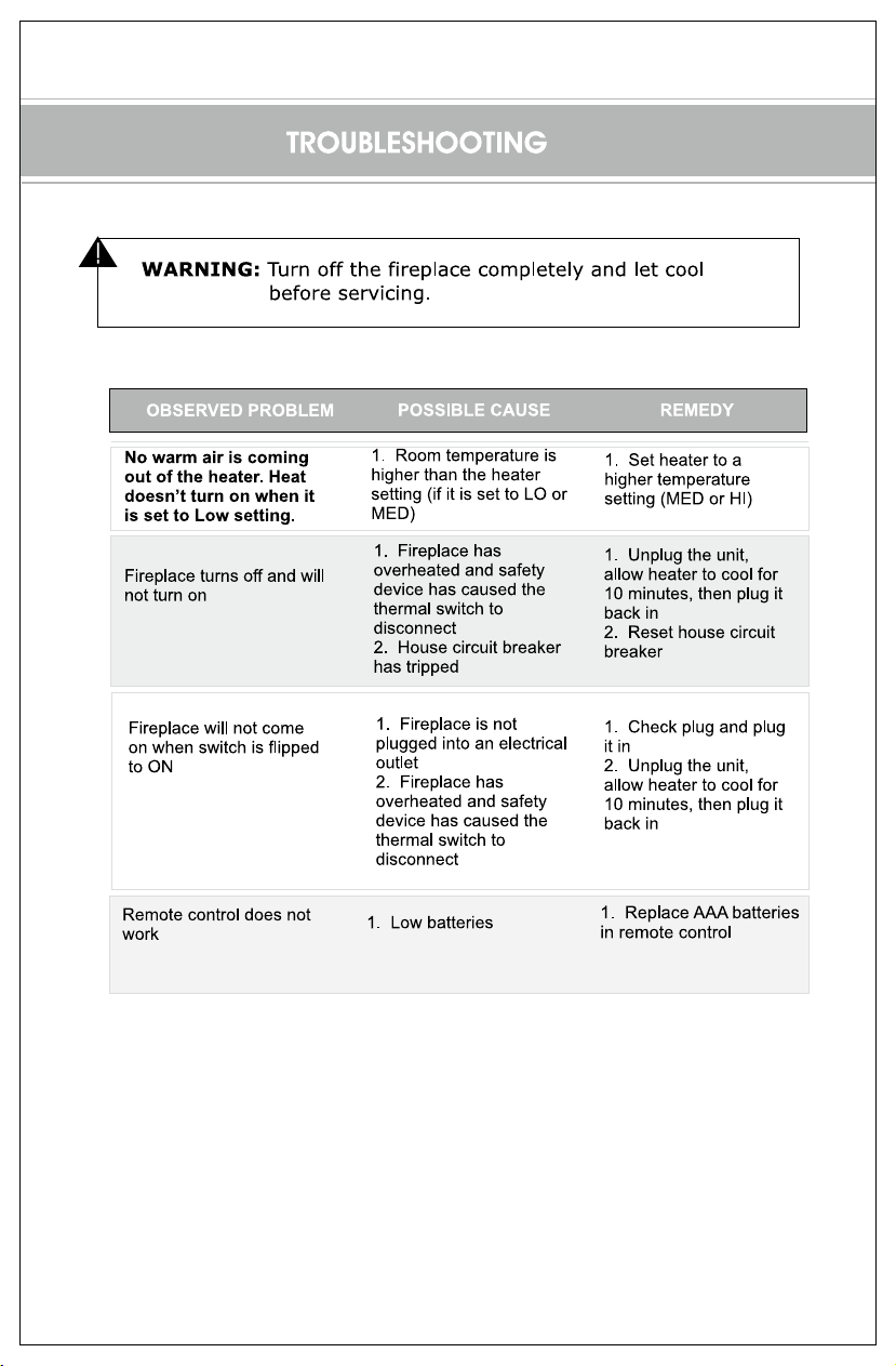
Troubleshooting
4-6
7
8
9
10
10
11-12
13
13-14
15
16
Replacing The Rock/Log Set
2
.
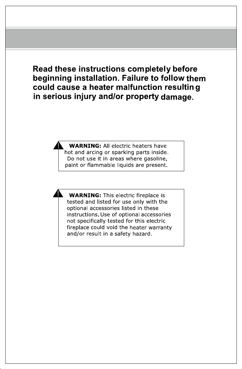
CAUTION:
&
A

IMPORT ANT SAFETY INSTRUCTIONS
7
.

SAVE THESE INSTRUCTIONS!
,60Hz
This heater has been tested in accordance with the CSA Standards.
X35WMEF
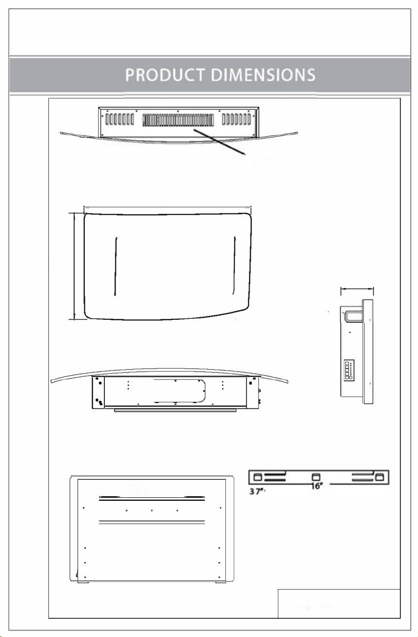
35.0"
c
,.
5.5"
16"
_ -
LOCATING FIREPLACE
�
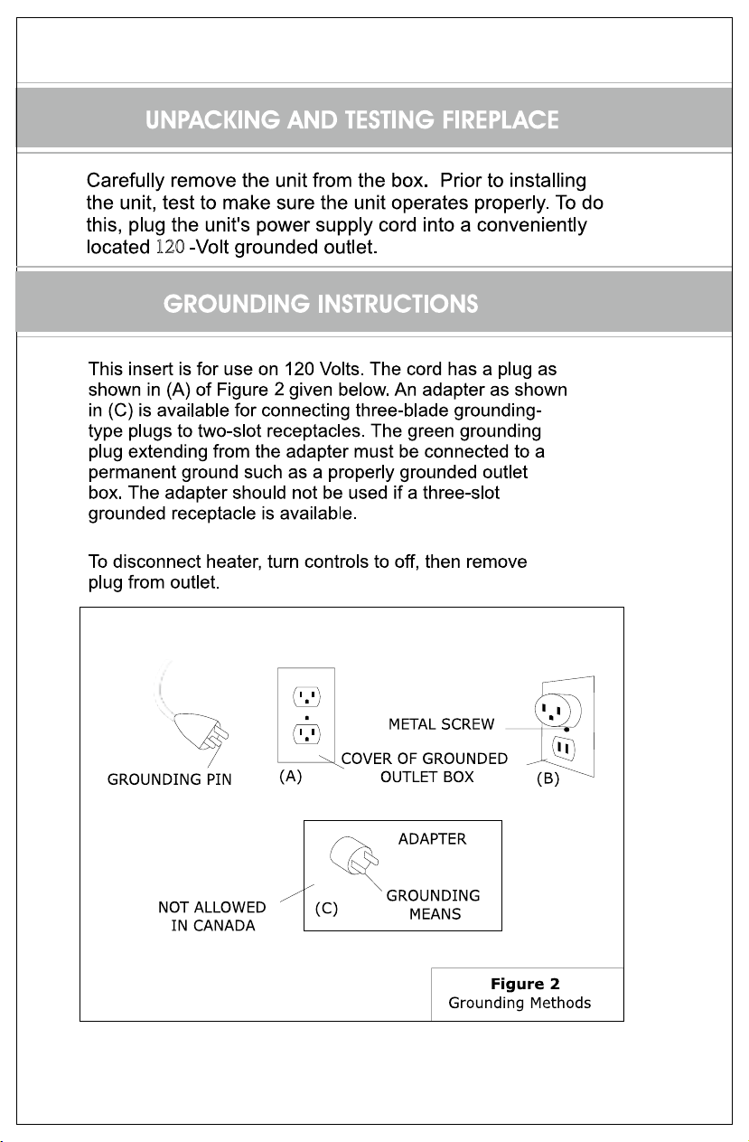
120
�
3
Main Power Switch:
Rr
ON RO" OFF.
I
"
®
I
I Figure 4
®
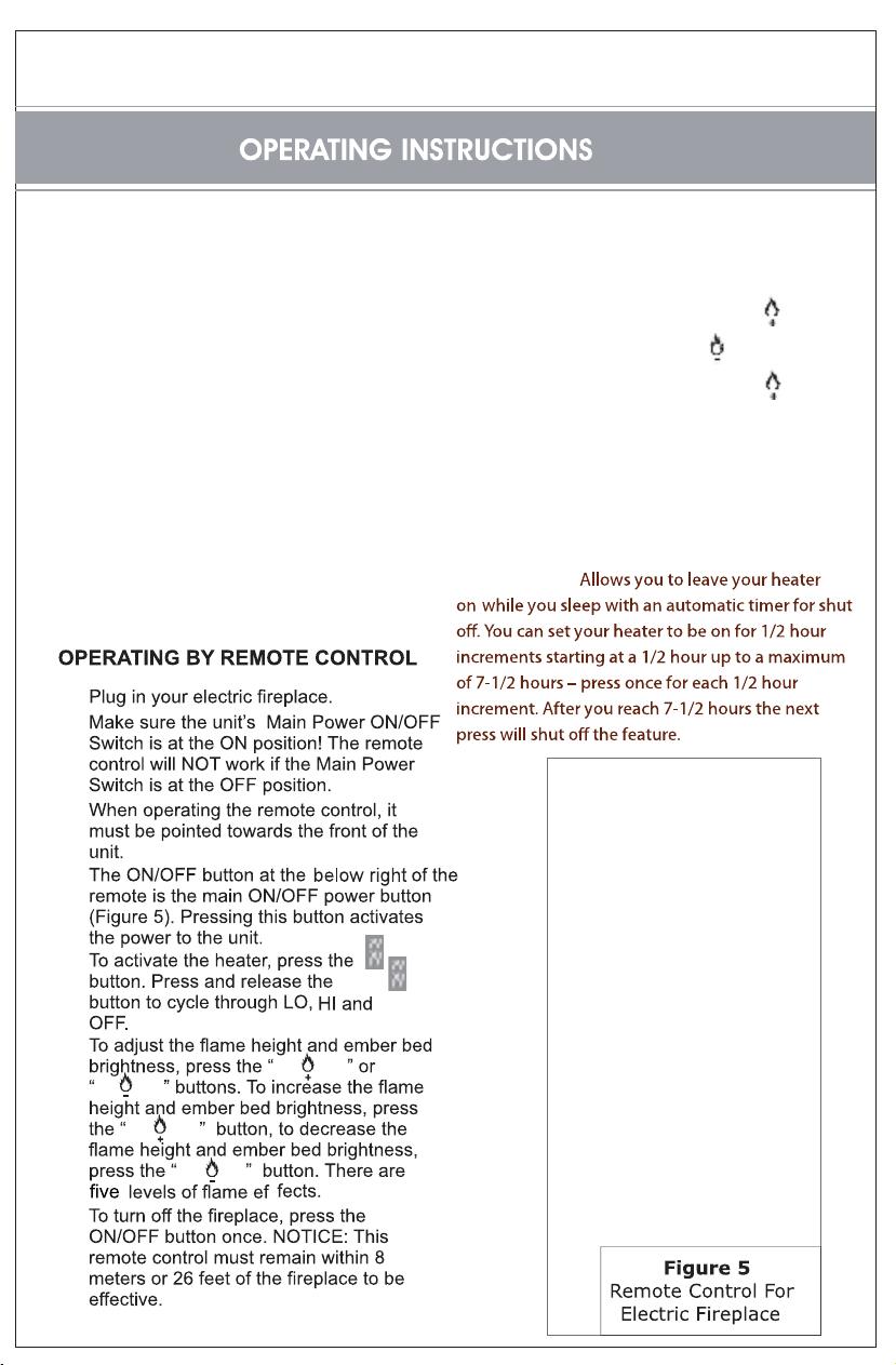
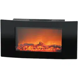
The manual controls are located on the left side of the fireplace.
:slortnoc gniwollof eht evah uoY
1. Power ON/OFF: Power to the
unit
2. Flame brightness controls: Allows you to adjust
the flame to suit your mood.Press
to
increase flame brightness and
to decrease
flame brightness.You must press the
button
Several times to see the full flame effect.
3. Low heat:700 watts
4. High heat: 1400 watts
Please note: The heater touchpanel
control must be
touched 2 times to achieve high heat.
5. Heater Timer:
1.
2.
3.
4.
5.
6.
7.

Replacing The Rock/Log Set
T
O CHANGE LOG/ROCK SET (NOTE: MAKE SURE FIREPLACE IS TURNED OFF AND HAS BEEN UNPLUGGE
D
F
ROM ELECTRICAL OUTLET BEFORE ATTEMPTING TO CHANGE THE LOG/ROCK SET):
1
. Place fireplace on a flat, level surface (FIG 1).
2
. Remove 3 screws located on each side of glass face of fireplace (FIG 2 and FIG 3).
3
. Remove screws that aach the log/rock set to the front of fireplace (FIG 4).
4
. Replace with the desired set(log/rock)and re-assemble new set by inserng and ghtenin
g
screws(FIG 5).
5
. Re-assemble glass face to fireplace by inserng and ghtening screws on both side of glass
face (FIG 6).
FIG 1
FIG 2
FIG 3
FIG 4 FIG 5 FIG 6
The remote takes 2 xAAA
batteries