Loading ...
Loading ...
Loading ...
En-6
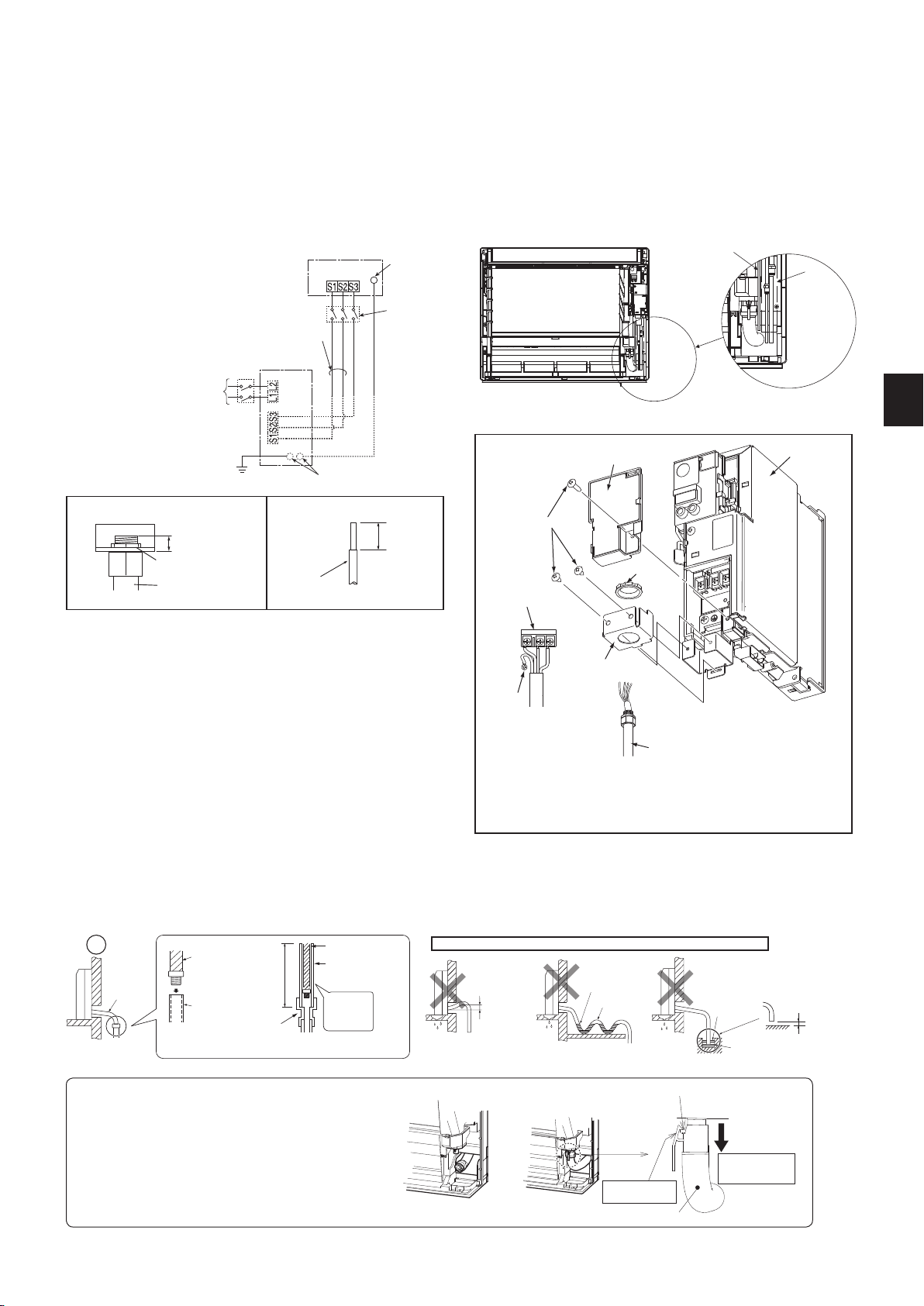
• Make earth wire a little longer than others. (More than 45 mm)
• For future servicing, give extra length to the connecting wires.
• Do not fold the excess wire, or cram it into small space. Take caution not to damage the
wires.
• Be sure to attach each screw to its correspondent terminal when securing the cord and/
or the wire to the terminal block.
INDOOR UNIT
Terminal block
208/230VAC
1phase,60Hz
Grounding
terminal*
Disconnect
switch
OUTDOOR UNIT
Grounding terminal*
Ground
Power supply
208/230 VAC,
1 phase 2 wires.
60 Hz
Terminal
block 1
Remark:
* Use a ring tongue terminal
in order to connect a ground
wire to terminal.
Terminal block 2
2-6. CONNECTING WIRES FOR INDOOR UNIT
Note: The unit should be installed by a licensed contractor/electrician. If required by applicable national, state and local codes; a disconnect switch will need to
be installed when the indoor unit is powered from the outdoor unit.
1) Remove the electrical cover.
2) Remove the conduit plate.
3) Attach the conduit pipe to the conduit plate with the lock nut. The indoor/outdoor unit connecting wire (A) appearing from the inside of conduit pipe should be
less than 7/8 in. (23 mm). (Fig. 1)
4) Process the end of ground wire (Fig. 2). Connect it to the ground terminal of the electrical parts box.
5) Process the end of indoor/outdoor unit connecting wire (A) (Fig. 2). Attach it to the terminal block. Be careful not to make mis-wiring. Attach the wire to the terminal
block securely so that its core cannot be seen, and no external force affects the connecting section of the terminal block.
6) Firmly tighten the terminal screws. After tightening, verify that the wires are tightly fastened.
7) Reinstall the conduit plate.
8) Reinstall the electrical cover.
Fig. 1
Lead
wire
19/32 in.
(15 mm)
Fig. 2
Terminal block
Lock nut
Electrical cover
Electrical box
Conduit pipe
Grounding
terminal
Screw
Less than 7/8 in.
(23 mm)
Conduit plate
Conduit pipe
Lock nut
Conduit plate
Do not make drain piping as shown below.
Accumulated
drain water
Air
Waving
Water
leakage
Do not raise
Water
leakage
Water
leakage
Tip of drain
hose dipped
in water
Ditch
At least
1-31/32 in.
(50 mm) gap
Downward
slope
Drain
hose
Soft hose I.D.
19/32 in.
(15 mm)
Drain hose
Hard vinyl chloride
pipe I.D. 1-3/16 in.
(30 mm)
Insert
securely
Different diameter joint
27-9/16 in.
(70 cm) or
more
Fig. 1 Fig. 2 Fig. 3
2-7. DRAIN PIPING
• If the extension drain hose has to pass through a room, be sure to wrap it with commercially sold insulation.
• Thedrainhoseshouldpointdownwardforeasydrainow.(Fig.1)
• Ifthedrainhoseprovidedwiththeindoorunitistooshort,connectitwithdrainhose(J)thatshouldbeprovidedatyoursite.(Fig.2)
• When connecting the drain hose to the hard vinyl chloride pipe, be sure to insert it securely into the pipe. (Fig. 3)
Fig. 5
Projection
Make sure to
hook the catch.
Drain hose
Pull the hose to
conrmit is con-
nected securely.
Fig. 4
The Drain hose is removed at installation.
• When routing the drain piping, make sure that the drain hose
(1) is routed as shown. (Fig. 4)
• Insert the drain hose all the way to the base of the drain
pan (end connection). (Fig. 5)
Make sure that the catch of the drain hose is securely
hookedontotheprojectiononthehosettingofthedrain
pan.
• After connecting the drain hose, be sure to pull the hose to
conrmthatitisconnectedsecurely.
Conduit pipe
Pipe
cover
RG79Y918H02_en.indd 6 2019/05/10 8:54:08
Loading ...
Loading ...
Loading ...