ご注意
スタンバイ状態がしばらく続くと、自動的に電源が切れます。再び、ス
タンバイ状態にするには、リモコンの
POWER
ボタン
(a)
を押して電源
を入れます。
動画を撮影するには
START/STOP
ボタン
(c)
または
(j)
を押す。
POWER/REC
ランプが赤色に点灯して、撮影が始まります。
撮影を止めるには、もう一度
START/STOP
ボタンを押す。
POWER/REC
ランプが緑色に点灯して、スタンバイ状態になります。
静止画を撮影するには
PHOTO
ボタン
(b)
または
(k)
を半押ししてピントを合わせてから、止ま
るまで押し込む。
ロック機構について(
B
)
バルブ撮影や連続撮影をするとき、
PHOTO
ボタン(
b
)を押した状態を
保持することができます。
PHOTO
ボタンを深く押し込んだまま、矢印の方向にスライドさせる。
バルブ撮影時はロックしている間、シャッターが開いています。
ˎ
連続撮影時はロックしている間、シャッターが切れ続けます。
ˎ
ご注意
バルブ撮影や連続撮影は全てのカメラで対応しているわけではあり
ˎ
ません。詳しくはカメラの取扱説明書をご参照ください。
故障の原因となる場合がありますので
PHOTO
ボタンを強く押し込
ˎ
んだり、強くスライドさせないでください。
REAR
側の
PHOTO
ボタン
ˎ
(k)
はロック機構に対応しておりません。
ロック状態のまま放置しないでください。
ˎ
リモコンの取りはずしについて(
C
)
静止画を撮影するときは、リモコンを取りはずして
PHOTO
ボタンを押
すと、ブレを防止することができます。
PUSH RELEASE
ボタン(
f
)を押し、片手で三脚を抑えながら、リモコン
を引き抜く。
リモコンを取り付ける際は、三脚を抑えながら
PUSH RELEASE
ボタン
(
f
)がカチッと音がするまでリモコンをゆっくり挿し込んでください。
ズームする
ズームレバー
(d)
または
(l)
を傾ける。
T
側(望遠):
被写体が大きく写る。
W
側(広角):
被写体が小さく写る。
ズームレバーを傾ける角度によって、ズーム速度が変わります。
スローズームする
SLOW ZOOM
スイッチ
(h)
を「
ON
」にする。
ズームレバーを傾ける角度に関係なく、ズームは遅い速度に固定され
ます。
スローズームを解除するには、
SLOW ZOOM
スイッチを「
OFF
」にす
る。
ご注意
スローズームの速度はカメラにより異なります。
ˎ
POWER/REC
ランプが赤色に点滅した場合は、画面に警告表示が
ˎ
出ています。カメラの表示を確認してください。
グリッドラインを表示させる(
D
)
GRID LINE
ボタン
(g)
を押す。
カメラの画面に水平・垂直のグリッドラインが表示されます。グリッ
ドラインに合わせて三脚の脚やティルティングを調節してください。
GRID LINE
ボタンは、
CONTROL
スイッチの位置に関わらず有効とな
ります。
お使いのカメラによってはグリッドラインを複数種類選択できます。
GRID LINE
ボタンを押すたびに切り替えることができます。
詳しくはカメラの取扱説明書をご参照ください。
グリッドライン表示を解除するには、表示が消えるまで
GRID LINE
ボ
タンを押してください。
写真はイメージです。実際の画面表示とは異なります。
*
撮影が終わったら
リモコンの
POWER
ボタンを押して電源を切る。
三脚をたたむ
1
三脚からカメラをはずす。
2
パンストッパー、ティルトストッパーをゆるめて、パンハンドルをたた
む。
3
パンストッパー、ティルトストッパーを締める。
4
3
本の脚の脚ロックレバーをゆるめて、脚をたたむ。
5
脚ロックレバーを締めて固定する。
持ち運びについて
キャリングケースに入れてください。
ご注意
カメラを取り付けたままで、持ち運ばないでください。
主な仕様
積載カメラ重量
5 kg
以下
パンニング角
360
度
ティルティング角
前傾
90
度、後傾
70
度
脚段数
3
段
リモコン機能
POWER
ボタン、
PHOTO
ボタン、
START/STOP
ボタン、ズームレバー(
T/W
)、
GRID LINE
ボタン、
PUSH RELEASE
ボタン、
SLOW ZOOM
スイッチ、
CONTROL
スイッチ
外形寸法
全高
約
1 505mm
(開脚角度
25
度)
縮長
開脚時
約
700mm
閉脚時
約
735mm
接続ケーブルの長さ
約
800mm
パンハンドルの長さ
約
360mm
使用温度範囲
0
℃
〜
40
℃
質量
約
3.4 Kg
付属品
キャリングケース(
1
個)
マルチ端子用接続ケーブル(
1
本)
A/V
リモート端子用接続ケーブル(
1
本)
LANC
端子
/
リモート端子用接続ケーブル(
1
本)
REMOTE
(リモート)端子用接続ケーブル(
1
本)
印刷物一式
仕様および外観は、改良のため予告なく変更することがあります。
保証書とアフターサービス
保証書
この製品には保証書が添付されていますので、お買い上げの際、お受け
ˎ
取りください。
所定
事項の記入および記載内容をお確かめのうえ、大切に保管してくだ
ˎ
さい。
保証期間は、お買い上げ日より
1
年間です。
ˎ
アフターサービス
調子が悪いときはまずチェックを
この取扱説明書をもう一度ご覧になってお調べください。
それでも具合の悪いときは
ソニーの相談窓口にご相談ください。
保証期間中の修理は
保証書の記載内容に基づいて修理させていただきます。詳しくは保証書を
ご覧ください。
保証期間経過後の修理は
修理によって機能が維持できる場合は、ご要望により有料修理させていた
だきます。
部品の保有期間について当社ではリモコン三脚の補修用性能部品(製品の
機能を維持するために必要な部品)を、製造打ち切り後
8
年間保有していま
す。ただし、故障の状況その他の事情により、修理に代えて製品交換をする
場合がありますのでご了承ください。
ご相談になるときは次のことをお知らせください。
型名:
ˎ
VCT-VPR100
故障の状態:できるだけ詳しく
ˎ
お買い上げ年月日
ˎ
「400」
リモコン三脚
Remote control Tripod
Trépied à télécommande
4-452-081-02(1)
取扱説明書
Operating Instructions
Mode d’emploi
Bedienungsanleitung
Manual de instrucciones
Gebruiksaanwijzing
VCT-VPR100
©2013 Sony Corporation Printed in China
カウンターバランス機構を内蔵していますので、転倒しにくくなってい
ˎ
ます。
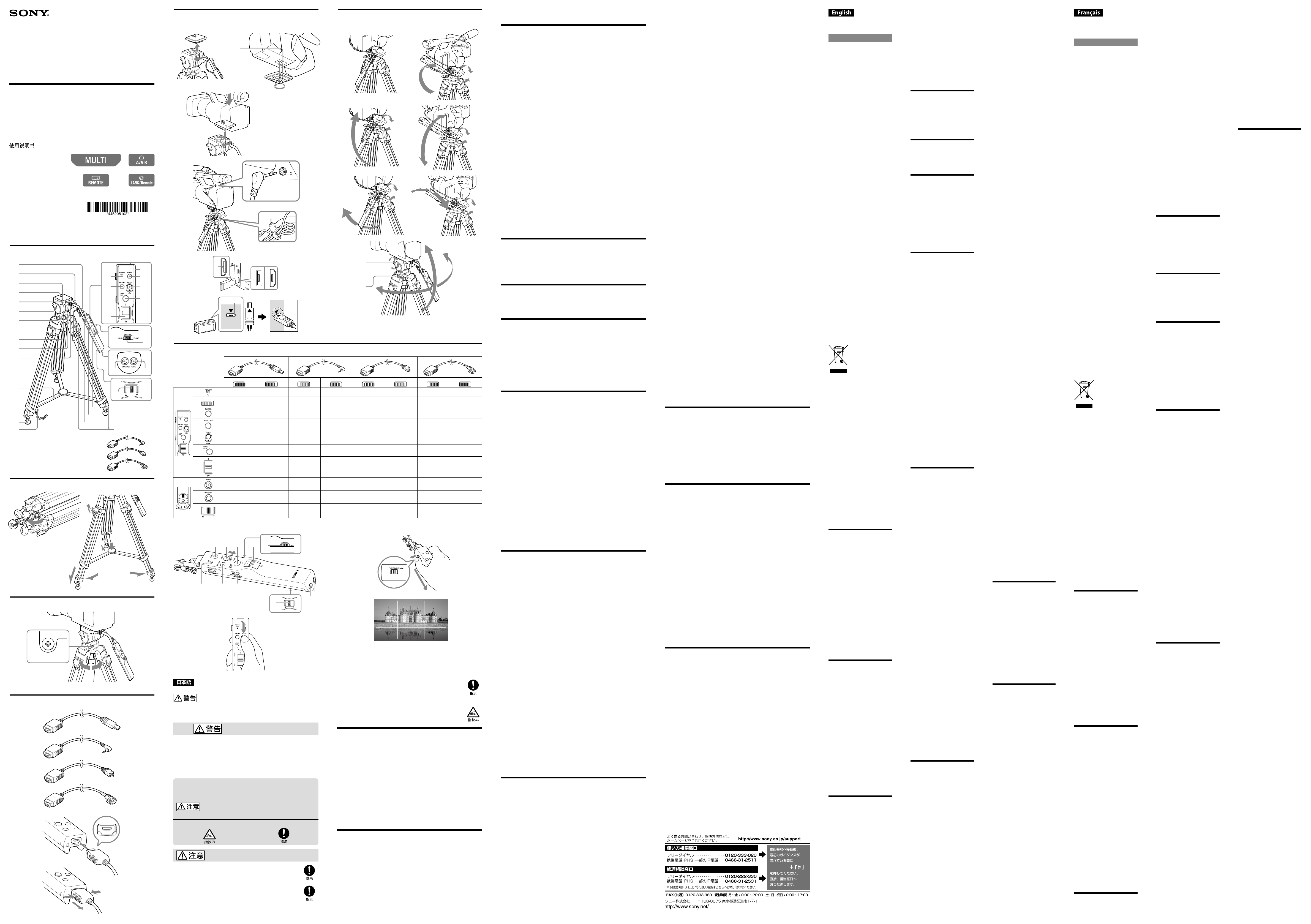
各部のなまえ
マルチ端子接続ケーブル
*
1
パンハンドルロックツマミ
2
カメラネジ
3
ビデオボス
4
クイックシュー
5
ティルトストッパー
6
パンストッパー
7
ボールレベルロックノブ
8
水準器
9
雲台
10
クイックシュー固定レバー
11
ステー
12
石突ゴム(スパイク付き)
13
脚ホルダー
14
POWER/REC
ランプ
15
GRID LINE
ボタン
16
ズームレバー
17
ストラップホール
18
POWER
ボタン
19
PHOTO
ボタン
20
START/STOP
ボタン
21
CONTROL
スイッチ
22
START/STOP
ボタン(逆手用)
23
PHOTO
ボタン(逆手用)
24
ズームレバー(逆手用)
25
パンハンドル
26
SLOW ZOOM
スイッチ
27
PUSH RELEASE
ボタン
28
脚ロックレバー
29
LANC
端子
/
リモート端子用接続ケーブル
30
A/V
リモート端子用接続ケーブル
31
REMOTE
(リモート)端子用接続ケーブル
32
*
本機とマルチ端子用接続ケーブルとは、一体で梱包された状態にて出荷
されています。
三脚を立てる
1
脚ホルダーをはずす。
2
脚を広げ、ステーを押し下げる。
3
脚ロックレバーを矢印の方向に起こしてロックを解除する。
4
脚を希望の長さに調節する。
5
脚ロックレバーを矢印の方向に戻して固定する。
水平の調整をする
1
ボールレベルロックノブをゆるめる。
2
水準器の中の気泡が赤い円の中に入るように、雲台の角度を調整する。
3
ボールレベルロックノブを締める。
接続ケーブルを取り付ける
お使いのカメラに合った接続ケーブルを、リモコンに取り付けてくださ
い。
ご注意
上下方向に気をつけて、イラストのプラグ
ˎ
a
部をリモコンに接続してく
ださい。
取りはずすときにはプラグ部分を持って取りはずしてください。ケー
ブ
ˎ
ル部分を引っ張ると破損する恐れがあります。
本機とマルチ端子用接続ケーブルとは、一体で梱包された状態にて出荷
ˎ
されています。
カメラを取り付ける
バッテリーやメモリーカードなどは、カメラを三脚に取り付ける前にセッ
トしておいてください。
1
クィックシュー固定レバーを左側に回し、クィックシューをはずす。
2
クイックシューのビデオボスとカメラネジを、カメラのボス穴(
a
)と三
脚用ネジ穴に合わせ、カメラネジをしっかり締める。
ご注意
ビデオカメラ以外のカメラでは、ビデオボスがカメラに干渉しない位
置で取り付けてください。
3
カメラネジのツマミを倒して、クイックシューを元の位置に差し込ん
で、カチッと音がするまで押し下げる。
押し下げたあと、念のためクイックシュー固定レバーを右側に押して
ください。
4
接続ケーブルの端子(
c
)をカメラの端子に接続する。
コードが長い場合は、コードクランパー
(b)
に挟んでください。
ご注意
マ
ルチ端子には、正しい挿入方向があります。逆向きのまま無理に
ˎ
挿し込むと、本機およびカメラを破損することがありますのでご注
意ください。
カメラのマルチ端子は
2
種類あります。
ˎ
マルチ端子用接続ケーブルを図
ˎ
(d)
の形状の本体のマルチ端子にさ
すときは、本体のマルチ端子「」とマルチ端子用接続ケーブルプ
ラグ部の「」をあわせて挿入してください。
逆方向に無理に差し込むと、故障の原因になります。
パンニング/ティルティング
パンハンドルの位置を調整する
まずパンハンドルを順手で使用するか、逆手で使用するかを決めます。
(A)
順手で使用する場合
(B)
逆手で使用する場合
パンハンドルロックツマミをゆるめる。
パンハンドルを逆手で使用できる位置にする。
パンハンドルロックツマミを締める。
上下方向の位置調整
(C)
順手で使用する場合
(D)
逆手で使用する場合
1
パンハンドルロックツマミをゆるめる。
2
使いやすい位置にする。
3
パンハンドルロックツマミを締める。
左右方向の位置調整
(E)
順手で使用する場合
(F)
逆手で使用する場合
4
パンハンドルロックツマミをゆるめる。
5
使いやすい位置にする。
6
パンハンドルロックツマミを締める。
パンニング(
G
)
カメラを水平方向に
360º
回転させて撮影することができます。
1
パンストッパー(
b
)をゆるめる。
2
パンハンドルを左右方向の希望の位置に動かす。
3
パンストッパーを締める。
ティルティング(
G
)
カメラを上下に動かして撮影することができます。
4
ティルトストッパー(
a
)をゆるめる。
5
パンハンドルを上下方向の希望の位置に動かす。
6
ティルトストッパーを締める。
ご注意
パンストッパーやティルトストッパーをトルクの重さ調整には絶対に使
用しないでください。故障の原因となります。確実にストッパーをゆるめ
てから、パンニング、ティルティングをしてください。
リモコンで操作する
お手持ちのカメラの取扱説明書もあわせてお読みください。
ご使用になるケーブルによって操作できるボタン/スイッチ/ランプの
対応が異なります(
A
)。
〇:有効(ご注意・カメラによっては対応していない場合もあります)
×:無効
CONTROL
スイッチ(
i
)で使用したいリモコンを選択する。
FRONT
(フロント):
前面のリモコンが使用できます。
(順手で使用する場合)
REAR
(リア):
底面と後面のリモコンが使用できます。
(逆手で使用する場合)
ご注意
REMOTE
(リモート)端子用接続ケーブル(
-32
)を使用しているとき
は、
CONTROL
スイッチの位置に関わらず、フロントの
PHOTO
ボタン
(b)
のみ有効です。その他のボタンやスイッチは無効です。
電源を入れる
1
カメラの電源を入れ、スタンバイ状態にする。
リモコンの
POWER/REC
ランプ
(e)
が緑色に点灯します。
2
カメラを動画または静止画の状態にする。
19
18
15
1
2
3
4
5
6
7
8
9
10
11
12
13
14
16
17
20
21
22
23
24
25
26
27
28
29
30
31
32
3
5
2
1
4
2
1 3
a b
11
2
1 2
a
3
4
c
b
MULTI
MULTI
d
1
Before operating the product, please
read this manual thoroughly and
retain it for future reference.
WARNING
To reduce the risk of fire or electric
shock,
1) do not expose the unit to rain or
moisture.
2) do not place objects filled with
liquids, such as vases, on the
apparatus.
This product has been tested and
found compliant with the limits set
out in the EMC regulation for using
connection cables shorter than 3
meters.
For Customers in the U.S.A.
CAUTION
You are cautioned that any changes or
modifications not expressly approved
in this manual could void your
authority to operate this equipment.
Note:
This equipment has been tested and
found to comply with the limits for
a Class B digital device, pursuant to
Part 15 of the FCC Rules.
These limits are designed to provide
reasonable protection against
harmful interference in a residential
installation. This equipment
generates, uses, and can radiate
radio frequency energy and, if not
installed and used in accordance
with the instructions, may cause
harmful interference to radio
communications. However, there is
no guarantee that interference will
not occur in a particular installation.
If this equipment does cause harmful
interference to radio or television
reception, which can be determined
by turning the equipment off and
on, the user is encouraged to try to
correct the interference by one or
more of the following measures:
Reorient or relocate the receiving –
antenna.
Increase the separation between the –
equipment and receiver.
Connect the equipment into –
an outlet on a circuit different
from that to which the receiver is
connected.
Consult the dealer or an –
experienced radio/TV technician
for help.
The supplied interface cable must be
used with the equipment in order to
comply with the limits for a digital
device pursuant to Subpart B of Part
15 of FCC Rules.
For the Customers in Europe
Disposal of Old Electrical &
Electronic Equipment (Applicable
in the European Union and other
European countries with separate
collection systems)
This symbol on the product or on
its packaging indicates that this
product shall not be treated as
household waste. Instead it shall
be handed over to the applicable
collection point for the recycling of
electrical and electronic equipment.
By ensuring this product is disposed
of correctly, you will help prevent
potential negative consequences for
the environment and human health,
which could otherwise be caused
by inappropriate waste handling
of this product. The recycling of
materials will help to conserve
natural resources. For more detailed
information about recycling of this
product, please contact your local
Civic Office, your household waste
disposal service or the shop where
you purchased the product.
Notice for the customers in the
countries applying EU Directives
The manufacturer of this product
is Sony Corporation, 1-7-1 Konan
Minato-ku Tokyo, 108-0075 Japan.
The Authorized Representative for
EMC and product safety is Sony
Deutschland GmbH, Hedelfinger
Strasse 61, 70327 Stuttgart, Germany.
For any service or guarantee matters
please refer to the addresses given
in separate service or guarantee
documents.
Precautions on Use
Removing the camera
Make sure that you hold on to ˎ
the camera when removing it.
The camera mounting shoe
automatically comes off the tripod
when you unlock the camera
mounting shoe lock lever, so the
camera may fall, if you are not
holding it.
Carrying the tripod
After using the tripod, ˎ remove
the camera, close the legs and
replace the pan handle to the
original position.
Never carry the tripod with the ˎ
camera attached.
Cleaning
When the tripod becomes dirty, ˎ
clean it with a soft cloth lightly
moistened with a mild detergent
solution. Then, wipe the tripod
clean with a dry cloth.
After using the tripod on the beach ˎ
or in places subject to sea breezes,
wipe it clean with a dry cloth.
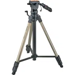
Features
The VCT-VPR100 is a tripod with
remote commander functionality for
cameras.
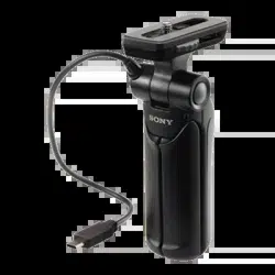
Remote commander built into the ˎ
pan/tilt handle which allows you to
operate a Sony camera with Multi
Terminal, A/V Remote Terminal,
LANC terminal/Remote Terminal,
or REMOTE Terminal. This tripod
may not be compatible with all
cameras. Please visit the Sony
website for the compatible models.
Remote commander functions ˎ
include basic recording functions
(POWER ON/OFF, video/still
image recording and zooming) and
SLOW ZOOM ON/OFF and grid
line display ON/OFF functions. You
can use the remote commander with
an ordinary grip (down position) or
reverse grip (up position).
Ball-leveler for quick and easy level ˎ
adjustment.
Smooth panning/tilting with an oil- ˎ
cylinder pan/tilt handle.
Built-in counterbalance mechanism ˎ
to prevent the tripod from toppling
over.
Identifying the Parts
Connecting cable for Multi 1
Terminal*
Pan/tilt handle lock screw2
Camera mounting screw3
Pin4
Camera mounting shoe5
Tilt lock knob6
Pan lock knob7
Ball-level lock knob8
Level9
Tripod head10
Camera mounting shoe lock 11
lever
Stay12
Ferrule (with a spike)13
Leg holder14
POWER/REC lamp 15
GRID LINE button16
Zoom lever (front)17
Strap hole18
POWER button19
PHOTO button (front)20
START/STOP button (front)21
CONTROL switch22
START/STOP button (bottom)23
PHOTO button (bottom)24
Zoom lever (rear)25
Pan/Tilt handle26
SLOW ZOOM switch27
PUSH RELEASE button28
Leg length adjustment lock lever29
Connecting cable for LANC 30
terminal/Remote Terminal
Connecting cable for A/V 31
Remote Terminal
Connecting cable for REMOTE 32
Terminal
* The tripod and the connecting cable
for Multi Terminal are included
together at the time of purchase.
Setting the Tripod
1 Remove the leg holder.
2 Spread the legs until the tripod
becomes stable.
3 Unlock the leg length adjustment
lock levers.
4 Adjust the length of the legs.
5 Lock the leg length adjustment
lock levers.
Adjusting the level
1 Unlock the ball-level lock knob.
2 Adjust the angle of the tripod
head so that the bubble in the
level moves inside the red ring.
3 Lock the ball-level lock knob.
Attaching the
connecting cable
Attach the adaptable connecting cable
of your camera to the terminal of the
Remote Commander.
Caution
Orientate plug “a” as illustrated ˎ
and insert it into the remote
commander.
Hold the plug when detaching the ˎ
cable. Pulling the cable itself could
damage the connector.
The tripod and the connecting cable ˎ
for Multi Terminal are included
together at the time of purchase.
Mounting the Camera
Install a battery pack, memory card,
etc. in the camera before mounting it
on the tripod.
1 Turn the camera mounting shoe
lock lever to the left to remove the
camera mounting shoe.
2 Align the pin (a) and the camera
mounting screw with the holes
on the bottom of the camera, and
tighten the screw firmly.
Caution
When attaching a camera other
than a video camera to the tripod,
position it so that it does not to
touch the pin for video cameras.
3 Collapse the camera mounting
screw and insert the camera
mounting shoe with the camera
attached into the tripod head
until it clicks into place.
Then, turn the camera mounting
shoe lock lever to the right to
make sure that it is locked.
4 Connect the terminal of the
connecting cable (c) to the
terminal of the camera.
If the cable is too long, clamp the
cable with a cable clamper (b).
Caution
The multi connector must be ˎ
inserted the right way up. Be
careful not to connect it upside
down or you may damage the
tripod or camera.
There are two types of camera ˎ
multi terminal.
When connecting the ˎ
connecting cable for multi
terminal to the multi terminal
of the camera (shaped as in
(d)), align the mark on the
plug with the mark on the
multi terminal. Forcing the plug
in the wrong way round will
cause a malfunction.
Panning/Tilting
Adjusting the position of the
pan/tilt handle
First determine the position in which
you want to use the pan/tilt handle
with an ordinary grip (down position)
or a reverse grip (up position).
(A) Using it with an ordinary grip
(down position)
(B) Using it with a reverse grip (up
position)
Loosen the pan/tilt handle lock
screw.
Turn the pan/tilt handle to a
reverse grip (up) position.
Tighten the pan/tilt handle lock
screw.
To adjust the vertical position:
(C) Using it with an ordinary grip
(down position)
(D) Using it with a reverse grip (up
position)
1 Loosen the pan/tilt handle lock
screw.
2 Adjust the angle of the pan/tilt
handle.
3 Tighten the pan/tilt handle lock
screw.
To adjust the horizontal
position:
(E) Using it with an ordinary grip
(down position)
(F) Using it with a reverse grip (up
position)
4 Loosen the pan/tilt handle lock
screw.
5 Adjust the angle of the pan/tilt
handle.
6 Tighten the pan/tilt handle lock
screw.
Panning (G)
You can pan 360° when shooting
pictures.
1 Loosen the pan lock knob (b).
2 Adjust the position of the camera
by moving the pan/tilt handle.
3 Tighten the pan lock knob.
Tilting (G)
You can tilt your camera up/down
when shooting pictures.
4 Loosen the tilt lock knob (a).
5 Adjust the position of the camera
by moving the pan/tilt handle.
6 Tighten the tilt lock knob.
Note
Do not adjust torque weight using the
pan lock knob or the tilt lock knob.
Doing so may cause a malfunction.
Do panning or tilting after loosening
each lock knob properly.
Using the Remote
Commander
Also see the operating instructions of
your camera.
The usable buttons, switches and
lamps vary depending on the
connecting cable used (A).
: Valid (Note: May be invalid with
some cameras)
: Invalid
Select the Remote Commander on the
pan/tilt handle by sliding the
CONTROL switch (i).
FRONT: When you use the Remote
Commander on the top surface of the
handle (using it with an ordinary grip
(down position)).
REAR: When you use the Remote
Commander on the bottom and the
back side of the handle (using it with
a reverse grip (up position)).
Caution
When using the Connecting cable for
REMOTE Terminal (-32), only
the PHOTO button (b) is available
regardless of the position of the
CONTROL switch. The other buttons
and switches do not work.
Turning on the power
1 Turn on the power of the camera
and set it to standby mode.
The POWER/REC lamp (e) of
the Remote Commander lights
in green.
2 Set the camera to the movie or
still image mode.
Caution
If you leave the camera in standby
mode for a while, the camera turns
off automatically. To resume standby
mode, turn on the camera, pressing
the POWER button (a) of the remote
commander.
To record a moving image
Press the START/STOP button (c)
or (j).
The POWER/REC lamp lights in red
and recording starts.
To stop recording, press the START/
STOP button again.
The POWER/REC lamp lights in
green. The camera is set to standby
mode.
To record a still image
Half-press the PHOTO button (b) or
(k) to bring the camera into focus,
and then press the button all the way.
Locking function (B)
During bulb shooting or continuous
shooting, you can set the PHOTO
button (b) so that it is held down.
With the PHOTO button fully pressed
down, slide it in the direction of the
arrow.
When the PHOTO button is locked ˎ
during bulb shooting, the shutter
is open.
When the PHOTO button is locked ˎ
during continuous shooting, the
shutter continues to open and close.
Caution
Not all cameras support bulb ˎ
shooting or continuous shooting.
See the operating instructions of
your camera for details.
Do not press the PHOTO button ˎ
with excessive force or the Remote
Commander may break.
You cannot use the locking function ˎ
when pressing the PHOTO button
(k).
Do not leave the PHOTO button ˎ
locked.
Detaching the Remote
Commander (C)
When shooting still photos, you can
prevent camera shake by detaching
the remote commander from the
tripod before pressing the PHOTO
button.
To detach the remote commander,
pull it out while holding the tripod
and pressing the PUSH RELEASE
button (f).
To attach the remote commander,
slowly slide the remote commander
on while holding the tripod until the
PUSH RELEASE button (f) clicks out.
Zooming
Tilt the zoom lever (d) or (l).
T side (telephoto): Subject appears
closer.
W side (wide angle): Subject appears
farther away.
The zooming speed changes
depending on the angle of zoom lever
when you tilt it.
Slow zooming
Set the SLOW ZOOM switch (h) to
ON.
Regardless of the tilt angle of zoom
lever, zooming is always performed at
slow speed.
To cancel the slow zooming function,
set the SLOW ZOOM switch to OFF.
Caution
The slow zooming speed varies ˎ
depending on a camera.
When the POWER/REC lamp ˎ
flashes in red, a warning message
is displayed on the camera. Check
the message on the screen of the
camera.
To display the grid line (D)
Press the GRID LINE button (g).
A horizontal/vertical grid line appears
on the camera screen.
Adjust the legs of the tripod and tilt
angle of your camera in accordance
with the grid line.
The GRID LINE button is available
regardless of the position of the
CONTROL switch.
You can choose multiple grid lines
depending on your camera model.
You can set the grid lines by pressing
the GRID LINE button.
See the operating instructions of your
camera for details.
To cancel the grid line display, press
the GRID LINE button until the grid
line display turns off.
* The photograph is just an example
of the screen. The actual screen to be
displayed may be different.
After recording
Press the POWER button of the
Remote Commander to turn off the
camera.
Folding the Tripod
1 Remove the camera from the
tripod.
2 Loosen the pan lock lever and tilt
lock lever and fold down the pan
handle.
3 Tighten the pan lock lever and tilt
lock lever.
4 Loosen the leg length adjustment
lock lever of the three legs and
fold the legs.
5 Tighten the leg length adjustment
lock lever to hold the legs in
place.
Carrying the tripod
Make sure to carry the tripod in its
carrying case.
Caution
Never carry the tripod with the
camera attached to it.
Specifications
Maximum load
5 kg (11 lb.)
Panning angle
360 degrees
Tilting angle
90 degrees down, 70 degrees up
Leg extension
Each leg has 3 telescoping shafts.
Remote Commander functions
POWER button, PHOTO button,
START/STOP button, zoom lever
(T/W), GRID LINE button, PUSH
RELEASE button, SLOW ZOOM
switch, CONTROL switch
Dimensions
Maximum height: Approx. 1 505
mm (59 3/8 inches) (Legs spread
at 25 degrees)
Minimum height: Approx.
700 mm (27 5/8 inches) (Legs
spread), Approx. 735 mm (29
inches) (Legs closed)
Remote Commander cable length
Approx. 800 mm (31 1/2 inches)
Pan handle length
Approx. 360 mm (14 1/4 inches)
Operating temperature range
0 °C to 40 °C (32 °F to 104 °F)
Mass
Approx. 3.4 kg (7 lb. 8 oz.)
Supplied accessories
Carrying case (1)
Connecting cable for Multi
Terminal (1)
Connecting cable for A/V
Remote Terminal (1)
Connecting cable for LANC
terminal/Remote Terminal (1)
Connecting cable for REMOTE
Terminal (1)
Set of printed documentation
Design and specifications are subject
to change without notice.
Avant de faire fonctionner ce produit,
lisez attentivement ce mode d’emploi
et conservez-le pour toute référence
ultérieure.
AVERTISSEMENT
Pour réduire les risques d’incendie ou
d’électrocution,
1) n’exposez pas l’appareil à la pluie ou
à l’humidité ;
2) ne placez pas d’objets remplis de
liquides (vases, etc.) sur l’appareil.
Cet appareil a été testé et jugé
conforme aux limites établies par
la Réglementation EMC visant
l’utilisation de câbles de raccordement
de moins de 3 mètres.
À l’intention des clients aux
É.-U.
AVERTISSEMENT :
Par la présente, vous êtes avisé du
fait que tout changement ou toute
modification ne faisant pas l’objet
d’une autorisation expresse dans le
présent manuel pourrait annuler votre
droit d’utiliser l’appareil.
Note :
L’appareil a été testé et est
conforme aux exigences d’un
appareil numérique de Classe B,
conformément à la Partie 15 de la
réglementation de la FCC.
Ces critères sont conçus pour fournir
une protection raisonnable contre
les interférences nuisibles dans un
environnement résidentiel. L’appareil
génère, utilise et peut émettre
des fréquences radio; s’il n’est pas
installé et utilisé conformément aux
instructions, il pourrait provoquer
des interférences nuisibles aux
communications radio.
Cependant, il n’est pas possible de
garantir que des interférences ne
seront pas provoquées dans certaines
conditions particulières. Si l’appareil
devait provoquer des interférences
nuisibles à la réception radio ou à la
télévision, ce qui peut être démontré
en allumant et éteignant l’appareil,
il est recommandé à l’utilisateur
d’essayer de corriger cette situation
par l’une ou l’autre des mesures
suivantes :
Réorienter ou déplacer l’antenne –
réceptrice.
Augmenter la distance entre –
l’appareil et le récepteur.
Brancher l’appareil dans une prise –
ou sur un circuit différent de celui
sur lequel le récepteur est branché.
Consulter le détaillant ou un –
technicien expérimenté en radio/
téléviseurs.
Le câble d’interface fourni doit être
utilisé avec l’appareil pour satisfaire
les limites relatives à un dispositif
numérique conformément à la Sous
partie B de l’article 15 du Règlement
de la FCC.
Pour les clients en Europe
Traitement des appareils
électriques et électroniques en fin
de vie (Applicable dans les pays de
l’Union Européenne et aux autres
pays européens disposant de
systèmes de collecte sélective)
Ce symbole, apposé sur le produit
ou sur son emballage, indique que
ce produit ne doit pas être traité avec
les déchets ménagers. Il doit être
remis à un point de collecte approprié
pour le recyclage des équipements
électriques et électroniques. En vous
assurant que ce produit sont mis
au rebut de façon appropriée, vous
participez activement à la prévention
des conséquences négatives que
leur mauvais traitement pourrait
provoquer sur l’environnement et
sur la santé humaine. Le recyclage
des matériaux contribue par ailleurs
à la préservation des ressources
naturelles. Pour toute information
complémentaire au sujet du recyclage
de ce produit, vous pouvez contacter
votre municipalité, votre déchetterie
locale ou le point de vente où vous
avez acheté le produit.
Avis aux consommateurs des pays
appliquant les Directives UE
Ce produit a été fabriqué par ou pour
le compte de Sony Corporation, 1-7-1
Konan Minato-ku Tokyo, 108-0075
Japon. Toutes les questions relatives à
la conformité des produits basées sur
la législation européenne doivent être
adressées à son représentant, Sony
Deutschland GmbH, Hedelfinger
Strasse 61, 70327 Stuttgart,
Allemagne.
Pour toute question relative au
Service Après-Vente ou à la Garantie,
merci de bien vouloir vous référer
aux coordonnées qui vous sont
communiquées dans les documents «
Service » (SAV) » ou Garantie.
Précautions d’emploi
Retrait de la caméra
Veillez à bien retenir la caméra ˎ
lorsque vous la retirez. Le sabot
de montage de caméra se détache
automatiquement du trépied lorsque
vous dévissez le levier de blocage
du sabot de montage de caméra,
de sorte que la caméra risque de
tomber, si vous ne la retenez pas.
Transport du trépied
Après avoir utilisé le trépied, ˎ
déposez la caméra, fermez les
pieds et remettez la poignée de
pan dans sa position d’origine.
Ne transportez jamais le trépied ˎ
avec la caméra rattachée.
Nettoyage
Quand le trépied est sale, nettoyez- ˎ
le avec un chiffon doux légèrement
imprégné d’une solution détergente
faible. Puis, essuyez le trépied avec
un chiffon sec.
Après avoir utilisé le trépied à la ˎ
plage ou à un endroit exposé aux
embruns marins, essuyez-le avec un
chiffon sec.
Caractéristiques
Le VCT-VPR100 est un trépied
pourvu d’une commande à distance
pour caméras.
La télécommande intégrée à la ˎ
poignée de rotation verticale/
horizontale permet des prises de
vue avec une caméra Sony pourvue
d’une multiprise, d’une prise de
commande à distance A/V, d’une
prise LANC/prise de commande à
distance ou d’une prise REMOTE.
Ce trépied peut ne pas être
compatible avec toutes les caméras.
Veuillez consulter le site de Sony
pour les modèles compatibles.
Les fonctions de la télécommande ˎ
comprennent les fonctions
essentielles d’enregistrement
(POWER ON/OFF, enregistrement
de films/photos et zooming) et
les fonctions SLOW ZOOM ON/
OFF et d’affichage de la grille
ON/OFF. Vous pouvez utiliser
la télécommande avec une prise
ordinaire (position basse) ou
inversée (position haute).
Rotule pour un ajustement rapide et ˎ
aisé du niveau.
Mouvement horizontal et vertical ˎ
régulier avec la poignée de rotation
horizontale/verticale à cylindre
hydraulique.
Mécanisme à contrepoids pour ˎ
empêcher le renversement du
trépied.
Identification des
éléments
Câble de raccordement pour 1
multiprises*
Vis de blocage de la poignée de 2
rotation horizontale/verticale
Vis de montage de caméra3
Goupille4
Sabot de montage de caméra5
Bouton de blocage de 6
l’inclinaison
Bouton de blocage du pan7
Bouton de blocage de la rotule8
Niveau9
Tête de trépied10
Levier de blocage du sabot de 11
montage de caméra
Étai12
Sabot (à pointe)13
Support de pied14
Témoin POWER/REC15
Touche GRID LINE16
Levier de zoom (avant)17
Trou de sangle18
Touche POWER19
Touche PHOTO (avant)20
Touche START/STOP (avant)21
Commutateur CONTROL22
Touche START/STOP (dessous)23
Touche PHOTO (dessous)24
Levier de zoom (arrière)25
Poignée de rotation horizontale/26
verticale
Commutateur SLOW ZOOM27
Touche PUSH RELEASE28
Levier de blocage du réglage de la 29
longueur du pied
Câble de raccordement pour 30
connecteur LANC/connecteur de
commande à distance
Câble de raccordement pour 31
connecteur de A/V commande
à distance
Câble de raccordement pour 32
connecteur REMOTE
* Le câble de raccordement pour
multiprises est livré avec le trépied
lors de l’achat.
Réglage du trépied
1 Retirez le support de pied.
2 Écartez les pieds jusqu’à ce que le
trépied soit stable.
3 Déverrouillez les leviers de
blocage du réglage de la longueur
des pieds.
4 Ajustez la longueur des pieds.
5 Verrouillez les leviers de blocage
du réglage de la longueur des
pieds.
Réglage du niveau
1 Déverrouillez le bouton de
blocage de la rotule.
2 Ajustez l’angle de la tête du
trépied de sorte que la bulle dans
le niveau bouge à l’intérieur de la
bague rouge.
3 Verrouillez le bouton de blocage
de la rotule.
Branchement
du câble de
raccordement
Branchez le câble de raccordement
approprié de votre caméra sur la prise
de la télécommande.
Attention
Orientez la fiche ˎ a de la façon
illustrée et insérez-la dans la
télécommande.
Tenez la fiche pour détacher le ˎ
câble. Le connecteur pourrait être
endommagé si vous tirez sur le câble
proprement dit.
Le câble de raccordement pour ˎ
multiprises est livré avec le trépied
lors de l’achat.
Montage de la caméra
Installez une batterie, une carte
mémoire, etc. dans la caméra avant de
la monter sur le trépied.
1 Tournez le levier de blocage du
sabot de montage de caméra vers
la gauche pour retirer le sabot de
montage de caméra.
2 Alignez la goupille (a) et la vis
de montage de caméra sur les
trous sous la caméra, puis serrez
fermement la vis.
Attention
Lorsque vous rattachez une
caméra autre qu’un caméscope au
trépied, positionnez-la de sorte
qu’elle ne touche pas la goupille
destinée aux caméscopes.
3 Rabattez la vis de montage de
caméra et insérez le sabot de
montage de caméra avec la
caméra rattachée dans la tête
de trépied jusqu’à ce qu’elle
s’encliquette.
Tournez ensuite le levier de
blocage du sabot de montage de
caméra vers la droite pour bien le
verrouiller.
4 Raccordez la fiche du câble de
raccordement (c) à la prise de la
caméra. Si le câble est trop long,
fixez-le avec le serre-câble (b).
Attention
Le multiconnecteur doit ˎ
être inséré dans le bon sens.
Veillez à ne pas le brancher à
l’envers sinon vous risqueriez
d’endommager le trépied ou la
caméra.
Il existe deux types de ˎ
multiprise sur les caméras.
Lorsque vous raccordez le ˎ
câble de raccordement pour
multiprise à la multiprise de la
caméra (forme indiquée dans
(d)), alignez le repère sur
la fiche et le repère sur la
multiprise. Insérer la fiche dans
le mauvais sens en forçant peut
causer une défectuosité.
Rotation horizontale/
verticale
Réglage de la position de
la poignée de rotation
horizontale/verticale
Déterminez d’abord la position à
laquelle vous voulez utiliser la poignée
de rotation horizontale/verticale avec
une prise ordinaire (position basse)
ou inversée (position haute).
(A) Utilisation avec une prise
ordinaire (position basse)
(B) Utilisation avec une prise inversée
(position haute)
Desserrez la vis de blocage de la
poignée de rotation horizontale/
verticale
Tournez la poignée de rotation
horizontale/verticale pour la
mettre en position de prise
inversée (haut).
Serrez la vis de blocage de la
poignée de rotation horizontale/
verticale.
Pour régler la position
verticale :
(C) Utilisation avec une prise
ordinaire (position basse)
(D) Utilisation avec une prise inversée
(position haute)
1 Desserrez la vis de blocage de la
poignée de rotation horizontale/
verticale
2 Réglez l’angle de la poignée de
rotation horizontale/verticale.
3 Serrez la vis de blocage de la
poignée de rotation horizontale/
verticale.
Pour régler la position
horizontale :
(E) Utilisation avec une prise
ordinaire (position basse)
(F) Utilisation avec une prise inversée
(position haute)
4 Desserrez la vis de blocage de la
poignée de rotation horizontale/
verticale.
5 Réglez l’angle de la poignée de
rotation horizontale/verticale.
6 Serrez la vis de blocage de la
poignée de rotation horizontale/
verticale.
Pan (G)
Vous pouvez effectuer des
mouvements horizontaux de 360°
pendant la prise de vue.
1 Desserrez le bouton de blocage
du pan (b).
2 Réglez la position de la caméra en
bougeant la poignée de rotation
horizontale/verticale.
3 Serrez le bouton de blocage du
pan.
Inclinaison (G)
Vous pouvez incliner la caméra vers le
haut ou le bas pendant la prise de vue.
4 Desserrez le bouton de blocage de
l’inclinaison (a).
5 Réglez la position de la caméra en
bougeant la poignée de rotation
horizontale/verticale.
6 Serrez le bouton de blocage de
l’inclinaison.
Remarque
N’ajustez pas le poids du couple avec
le bouton de blocage du pan ou le
bouton de blocage de l’inclinaison.
Ceci peut causer une défaillance.
Desserrez correctement chaque
bouton de blocage avant de pratiquer
une rotation horizontale ou verticale.
Utilisation de la
télécommande
Reportez-vous aussi au mode d’emploi
de votre caméra.
Les touches, commutateurs et témoins
utilisables dépendent du câble de
raccordement utilisé (A).
: Valide (Remarque : Peut être
invalide pour certaines caméras.
: Invalide
Sélectionnez la télécommande sur
la poignée de rotation horizontale/
verticale en poussant le commutateur
CONTROL (i).
AVANT : Pour utiliser la
télécommande sur le haut de la
poignée (avec une prise ordinaire
(position basse)).
ARRIÈRE : Pour utiliser la
télécommande sur le bas et l’arrière
de la poignée (avec une prise inversée
(position haute)).
Attention
Si vous utilisez le câble de
raccordement pour connecteur
REMOTE (-32), seule la touche
PHOTO (b) est disponible, quelle
que soit la position du commutateur
CONTROL. Les autres touches et
commutateurs ne fonctionnent pas.
Mise sous tension
1 Mettez la caméra sous tension
puis en mode de veille.
Le témoin POWER/REC (e) de la
télécommande s’allume en vert.
2 Mettez la caméra en mode film
ou photo.
Attention
Si vous laissez la caméra en mode de
veille pendant un certain temps, elle
s’éteindra automatiquement. Pour
revenir au mode de veille, allumez
l’appareil photo, tout en appuyant
sur la touche POWER (a) de la
télécommande.
Pour filmer
Appuyez sur la touche START/STOP
(c) ou (j).
Le témoin POWER/REC s’allume en
rouge et l’enregistrement commence.
Pour arrêter l’enregistrement, appuyez
une nouvelle fois sur la touche
START/ STOP.
Le témoin POWER/REC s’allume en
vert. La caméra se met en mode de
veille.
Pour prendre une photo
Appuyez légèrement sur la touche
PHOTO (b) ou (k) et maintenez-la
enfoncée pour faire la mise au point,
puis appuyez à fond sur la touche
pour prendre la photo.
Fonction de verrouillage (B)
Pendant la prise de vue en pose B ou
en rafale, la touche PHOTO (b) peut
être réglée pour rester enfoncée.
La touche PHOTO étant
complètement enfoncée, faites-la
glisser dans le sens de la flèche.
Lorsque la touche PHOTO est ˎ
verrouillée pendant la prise de vue
en pose B, l’obturateur est ouvert.
Lorsque la touche PHOTO est ˎ
verrouillée pendant la prise de vue
en rafale, l’obturateur continue de
s’ouvrir et de se fermer.
Attention
Toutes les caméras ne prennent pas ˎ
en charge la prise de vue en pose B
ou en rafale.
Reportez-vous au mode d’emploi de
votre caméra pour le détail.
N’appuyez pas trop fort sur ˎ
la touche PHOTO sinon la
télécommande pourrait se briser.
Vous ne pouvez pas utiliser la ˎ
fonction de verrouillage quand vous
appuyez sur la touche PHOTO (k).
Ne laissez pas la touche PHOTO ˎ
verrouillée.
Dépose de la télécommande (C)
Quand vous prenez des photos, vous
pouvez éviter de bouger la caméra
en détachant la télécommande du
trépied avant d’appuyer sur la touche
PHOTO.
Pour détacher la télécommande, tirez
dessus tout en retenant le trépied
et appuyant sur la touche PUSH
RELEASE (f).
Pour fixer la télécommande, faites-la
glisser lentement sur la poignée tout
en tenant le trépied jusqu’à ce que la
touche PUSH RELEASE (f) ressorte.
Zooming
Inclinez le levier de zoom (d) ou (l).
Côté T (téléobjectif) : le sujet apparaît
plus près.
Côté W (grand-angle) : le sujet
apparaît plus loin.
La vitesse du zooming change selon
l’angle d’inclinaison du levier de
zoom.
Zooming lent
Réglez le commutateur SLOW ZOOM
(h) sur ON.
Quel que soit l’angle d’inclinaison
du levier de zoom, le zooming est
toujours lent.
Pour annuler le zooming lent, réglez
le commutateur SLOW ZOOM sur
OFF.
Attention
La vitesse du zooming lent dépend ˎ
de la caméra.
Lorsque le témoin POWER/REC ˎ
clignote en rouge, un message
d’avertissement apparaît sur la
caméra. Vérifiez le message qui
apparaît sur l’écran de la caméra.
Pour afficher la grille (D)
Appuyez sur la touche GRID LINE
(g).
Une grille aux lignes verticales et
horizontales apparaît sur l’écran de la
caméra.
Réglez les pieds du trépied et l’angle
d’inclinaison de la caméra en utilisant
la grille comme guide.
La touche GRID LINE est disponible
quelle que soit la position du
commutateur CONTROL.
Selon le modèle de caméra, vous
pouvez avoir le choix entre plusieurs
types de grilles.
La grille s’affiche ou est masquée à
chaque pression sur la touche GRID
LINE.
Reportez-vous au mode d’emploi de
votre caméra pour le détail.
Pour annuler l’affichage de la grille,
appuyez sur la touche GRID LINE
jusqu’à ce que la grille soit masquée.
* La photographie n’est qu’un exemple
d’écran. L’écran réellement affiché
peut être différent.
Après l’enregistrement
Appuyez sur la touche POWER de la
télécommande pour mettre la caméra
hors tension.
(Suite à la page arrière)
B
a b c d
i
f
j
k
g h
e
l
A
CONTROL
REAR FRONT
CONTROL
REAR FRONT
CONTROL
REAR FRONT
CONTROL
REAR FRONT
CONTROL
REAR FRONT
CONTROL
REAR FRONT
CONTROL
REAR FRONT
CONTROL
REAR FRONT
SLOW ZOOM
ON OFF
(A) (B)
(C) (D)
2
3
1
2
3
1
(E) (F)
5
4
6
5
6
4
(G)
6
5
2
4
3
1
a
b
1
C
1
2
D
*
お買い上げいただきありがとうございます。
電気製品は安全のための注意事項を守らないと、火災や人身事故に
なることがあります。
この取扱説明書には、事故を防ぐための重要な注意事項と製品の取り扱いかたを示
しています。この取扱説明書をよくお読みのうえ、製品を安全にお使いください。
お読みになったあとは、いつでも見られるところに必ず保管してください。
安全のために
ソニー製品は安全に充分配慮して設計されています。しかし、まちがった
使いかたをすると、火災などにより人身事故になることがあり危険です。
事故を防ぐために次のことを必ずお守りください。
●安全のための注意事項を守る
●故障したら使わずに、お買い上げ店またはソニーの相談窓口に修理を依
頼する
警告表示の意味
取扱説明書では、次のような表示をしています。表示の内容をよく理
解してから本文をお読みください。
この表示の注意事項を守らないと、感電やその他の事故に
よりけがをしたり周辺の家財に損害を与えたりすることが
あります。
注意を促す記号
行為を指示する記号
下記の注意事項を守らないと、
けが
をすることがあります。
開脚してからカメラを取り付ける
脚を閉じたまま取り付けると、転倒してカメラを破損したり
けがの原因となることがあります。
積載カメラ重量を守る
制限重量を超えると、三脚が倒れたりしてけがの原因となること
があります。
各ロックつまみやレバーおよび脚ロックレバー、カメラネジなど
の締め付けパーツは確実に締め付けて固定する
締め付けが弱いと、ずれたりはずれたりして、カメラの破損や人
にけがを負わせる原因となることがあります。
脚の出し入れには充分注意をはらう
指などをはさみ、思わぬけがをすることがあります。
使用上のご注意
カメラを取りはずすには
必ず、カメラを持ってはずしてください。クイックシュー固定レバーをゆ
るめると、クイックシューが自動的に三脚からはずれ、カメラが落下する
恐れがあります。
持ち運びについて
使い終わったら、
ˎ カメラをはずし、脚を収納し、パンハンドルの
操作部を外側に向けてたたんでください。
カメラを取り付けたままで、持ち歩かないでください。
ˎ
お手入れについて
汚れたら、やわらかい布に中性洗剤溶液を含ませてふいてから、乾いた
ˎ
布でからぶきしてください。
海岸など、潮風の当たる所で使用したあとは、乾いた布でよくふいてく
ˎ
ださい。
特長
この三脚はカメラなどにお使いいただける、リモコン機能付き三脚です。
パンハンドルのリモコンで、ソニーの「マルチ端子」または「
A/V
リモー
ˎ
ト端子」または「
LANC
端子
/
リモート端子」または「
REMOTE
(リモート)
端子」付きカメラを操作することがで
きます。す
べてのカメラに対応し
ている訳ではありません。
対応機種については、ホームページ、カタログ
等をご確認ください。
リモコンには撮影の基本機能(電源の
ON/OFF
、動画撮影・静止画撮影、
ˎ
ズーム)のほか、スローズームの
ON/OFF
、グリッドライン表示の
ON/
OFF
機能があります。リモコンは順手での使用のほか、状況に応じて逆
手での使用も可能です。
ボールレベラー方式ですので、正確な水平出しがすばやくできます。
ˎ
油圧式パンハンドルですので、パン/ティルトを滑らかに行えます。
ˎ
autorizado, Sony Deutschland
GmbH, Hedelfinger Strasse 61, 70327
Stuttgart, Alemania. Para cualquier
asunto relacionado con el servicio
o la garantía, por favor diríjase a la
dirección indicada en los documentos
de servicio o garantía adjuntados con
el producto.
Precauciones para la
utilización
Desmontaje de la cámara
Cerciórese de sujetar la cámara ˎ
cuando la desmonte. La zapata
de montaje de la cámara se
desprenderá automáticamente
del trípode cuando desbloquee su
palanca de bloqueo, por lo que la
cámara puede caerse si no la sujeta.
Transporte del trípode
Después de haber utilizado el ˎ
trípode, desmonte la cámara,
pliegue las patas, y devuelva
el mango de panoramización
horizontal a su posición original.
No transporte nunca el trípode con ˎ
la cámara instalada.
Limpieza
Cuando el trípode se ensucie, ˎ
límpielo con un paño suave
ligeramente humedecido en una
solución de detergente poco
concentrado. Después, frótelo con
un paño seco.
Después de haber utilizado el ˎ
trípode en una playa o en lugares
sometidos a brisas marinas, frótelo
con un paño seco.
Características
El VCT-VPR100 es un trípode con
funcionalidad de controlador remoto
para cámaras.
Controlador remoto incorporado ˎ
en el mango de panoramización
horizontal/vertical que le permite
controlar una cámara Sony con
terminal múltiple, terminal remoto
de A/V, terminal LANC/terminal
remoto, o terminal REMOTE. Este
trípode puede no ser compatible
con todas las cámaras. Con respecto
a los modelos compatibles, visite en
sitio web de Sony.
Las funciones del controlador ˎ
remoto incluyen las básicas de
grabación (POWER ON/OFF,
grabación de vídeo/imágenes fijas,
y zoom), y las funciones SLOW
ZOOM ON/OFF y visualización
ON/OFF de línea de rejilla. Puede
utilizar el controlador remoto con
un agarre normal (posición hacia
abajo) o un agarre inverso (posición
hacia arriba).
Nivelador de bola para ajuste rápido ˎ
y fácil del nivel.
Panoramización horizontal/vertical ˎ
con un mango de panoramización
horizontal/vertical de cilindro de
aceite.
Mecanismo de contrapeso ˎ
incorporado para evitar que el
trípode vuelque.
Identificación de
partes
Cable conector para terminal 1
múltiple*
Tornillo de bloqueo del mango 2
de panoramización horizontal/
vertical
Tornillo de montaje de cámara3
Pasador4
Zapata de montaje de cámara5
Perilla de bloqueo de 6
panoramización vertical
Perilla de bloqueo de 7
panoramización horizontal
Perilla de bloqueo del nivelador 8
de bola
Nivel9
Cabeza del trípode10
Palanca de bloqueo de la zapata 11
de montaje de cámara
Abrazadera12
Contera (con una púa)13
Soporte de las patas14
Lámpara POWER/REC15
Botón GRID LINE16
Palanca de zoom (frontal)17
Orificio para correa18
Botón POWER19
Botón PHOTO (frontal)20
Botón START/STOP (frontal)21
Selector CONTROL22
Botón START/STOP (inferior)23
Botón PHOTO (inferior)24
Palanca de zoom (posterior)25
Mango de panoramización 26
horizontal/vertical
Selector SLOW ZOOM27
Botón PUSH RELEASE28
Palanca de bloqueo de ajuste de 29
longitud de las patas
Cable conector para terminal 30
LANC /terminal remoto
Cable conector para terminal 31
remoto de A/V
Cable conector para terminal 32
REMOTE
* El trípode y el cable conector para
terminal múltiple se incluyen juntos
en el momento de la adquisición.
Ajuste del trípode
1 Retire el soporte de las patas.
2 Despliegue las patas hasta que el
trípode quede estable.
3 Desbloquee las palancas de
bloqueo de ajuste de la longitud
de las patas.
4 Ajuste la longitud de las patas.
5 Bloquee las palancas de bloqueo
de ajuste de la longitud de las
patas.
Ajuste del nivel
1 Desbloquee la perilla de bloqueo
del nivelador de bola.
2 Ajuste el ángulo de la cabeza del
trípode de forma que la burbuja
del nivelador permanezca dentro
del círculo rojo.
3 Bloquee la perilla de bloqueo del
nivelador de bola.
Fijación del cable
conector
Fije el cable conector adaptable de su
cámara al terminal del controlador
remoto.
Precaución
Oriente la clavija “a” como se ˎ
muestra en la ilustración e insértela
en el controlador remoto.
Sujete la clavija cuando desconecte ˎ
el cable. Si tirase del propio cable
podría dañar el conector.
El trípode y el cable conector para ˎ
terminal múltiple se incluyen juntos
en el momento de la adquisición.
Montaje de la cámara
Instale una batería, tarjeta de
memoria, etc., en la cámara antes de
montarla en el trípode.
1 Gire la palanca de bloqueo de la
zapata de montaje de la cámara
hacia la izquierda para retirar
dicha zapata.
2 Alinee el pasador (a) y el tornillo
de montaje de la cámara con los
orificios de la parte inferior de la
cámara, y apriete firmemente el
tornillo.
Precaución
Cuando instale una cámara que
no sea videocámara en el trípode,
colóquela de forma que no toque
el pasador para videocámaras.
3 Pliegue el tornillo de montaje
de la cámara e inserte la zapata
de montaje de la cámara con la
cámara fijada en la cabeza del
trípode hasta que chasquee en su
lugar.
Después, gire la palanca de
bloqueo de la zapata de montaje
de la cámara hacia la derecha para
asegurarse de que esté bloqueada.
4 Conecte el terminal del cable
conector (c) al terminal de la
cámara. Si el cable es demasiado
largo, sujételo con una abrazadera
de cable (b).
Precaución
El conector múltiple deberá ˎ
insertarse con el lado correcto
hacia arriba. Tenga cuidado de
no conectarlo al revés ya que
podría dañar el trípode o la
cámara.
Hay dos tipos de terminal ˎ
múltiple de cámara.
Cuando conecte el cable ˎ
conector para terminal múltiple
en el terminal múltiple de la
cámara (en forma como en (d)),
alinee la marca de la clavija
con la marca del terminal
múltiple. La inserción de la
clavija por la fuerza al revés
causará un mal funcionamiento.
Panoramización
horizontal y vertical
Ajuste de la posición del mango de
panoramización horizontal/vertical
En primer lugar determine la forma
en la que desea utilizar el mango de
panoramización horizontal/vertical
con un agarre normal (posición hacia
abajo) o un agarre inverso (posición
hacia arriba).
(A) Utilización con un agarre normal
(posición hacia abajo)
(B) Utilización con un agarre inverso
(posición hacia arriba)
Afloje el tornillo de bloqueo
del mango de panoramización
horizontal/vertical.
Gire el mango de panoramización
horizontal/vertical para una
posición de agarre inverso (hacia
arriba).
Apriete el tornillo de bloqueo
del mango de panoramización
horizontal/vertical.
Para ajustar la posición
vertical:
(C) Utilización con un agarre normal
(posición hacia abajo)
(D) Utilización con un agarre inverso
(posición hacia arriba)
1 Afloje el tornillo de bloqueo
del mango de panoramización
horizontal/vertical.
2 Ajuste el ángulo del mango de
panoramización horizontal/
vertical.
3 Apriete el tornillo de bloqueo
del mango de panoramización
horizontal/vertical.
Para ajustar la posición
horizontal:
(E) Utilización con un agarre normal
(posición hacia abajo)
(F) Utilización con un agarre inverso
(posición hacia arriba)
4 Afloje el tornillo de bloqueo
del mango de panoramización
horizontal/vertical.
5 Ajuste el ángulo del mango de
panoramización horizontal/
vertical
6 Apriete el tornillo de bloqueo
del mango de panoramización
horizontal/vertical.
Panoramización horizontal (G)
Puede realizar una panoramización
horizontal de 360° cuando esté
tomando imágenes.
1 Afloje la perilla de bloqueo de
panoramización horizontal (b).
2 Ajuste de la posición de la
cámara moviendo el mango de
panoramización horizontal/
vertical.
3 Apriete la perilla de bloqueo de
panoramización horizontal.
Panoramización vertical (G)
Puede realizar una panoramización
vertical hacia arriba/abajo cuando
esté tomando imágenes.
4 Afloje la perilla de bloqueo de
panoramización vertical (a).
5 Ajuste de la posición de la
cámara moviendo el mango de
panoramización horizontal/
vertical.
6 Apriete la perilla de bloqueo de
panoramización vertical.
Nota
No ajuste el peso de torsión
utilizando la perilla de bloqueo de
panoramización horizontal ni la de
panoramización vertical.
Si lo hicieses, podría causar un mal
funcionamiento.
Realice la panoramización horizontal
o vertical después de haber aflojado
adecuadamente cada perilla de
bloqueo.
Utilización del
controlador remoto
Consulte el manual de instrucciones
de su cámara.
Los botones, selectores y lámparas
utilizables variarán dependiendo del
cable conector utilizado (A).
: Válido (Nota: Puede no ser válido
con algunas cámaras)
: No válido
Seleccione el controlador remoto
en el mango de panoramización
horizontal/vertical deslizando el
selector CONTROL (i).
FRONT: Cuando utilice el
controlador remoto en la superficie
superior del mango (usándolo con un
agarre normal (posición hacia abajo)).
REAR: Cuando utilice el controlador
remoto en la superficie superior
del mango (usándolo con un agarre
normal (posición hacia arriba)).
Precaución
Cuando utilice el cable conector
para el terminal REMOTE (-32),
solamente estará disponible el botón
PHOTO (b) independientemente de
la posición del selector CONTROL.
Los demás botones y selectores no
trabajarán.
Conexión de la alimentación
1 Conecte la alimentación de la
cámara y póngala en el modo de
espera.
La lámpara POWER/REC (e) del
controlador remoto se encenderá
en verde.
2 Ponga la cámara en el modo de
película o imagen fija.
Precaución
Si deja la cámara en el modo de
espera durante cierto tiempo,
su alimentación se desconectará
automáticamente. Para reanudar
el modo de espera, conecte la
alimentación de la cámara pulsando
el botón POWER (a) del controlador
remoto.
Para grabar imágenes en
movimiento
Pulse el botón START/STOP (c) o (j).
La lámpara POWER/REC se
encenderá en rojo y se iniciará la
grabación.
Para detener la grabación, pulse de
nuevo el botón START/STOP.
La lámpara POWER/REC se
encenderá en verde. La cámara
entrará en el modo de espera.
Para grabar una imagen fija
Pulse el botón PHOTO (b) o (k) hasta
la mitad para enfocar la cámara, y
después púlselo a fondo.
Función de bloqueo (B)
Para la toma con obturación manual
o la toma continua, puede ajustar el
botón PHOTO (b) de forma que se
mantenga pulsado.
Con el botón PHOTO pulsado a
fondo, deslícelo en el sentido de la
flecha.
Cuando el botón PHOTO esté ˎ
bloqueado para la toma con
obturación manual, el obturador
estará abierto.
Cuando el botón PHOTO esté ˎ
bloqueado para la toma continua,
el obturador continuará abriendo y
cerrándose.
Precaución
No todas las cámaras admiten la ˎ
toma con obturación manual o
la toma continua. Con respecto a
los detalles, consulte el manual de
instrucciones de su cámara.
No pulse el botón PHOTO con ˎ
demasiada fuerza porque podría
romper el controlador remoto.
No puede utilizar la función de ˎ
bloqueo cuando pulse el botón
PHOTO (k).
No deje el botón PHOTO ˎ
bloqueado.
Desmontaje del controlador
remoto (C)
Cuando tome fotografías, podrá
evitar que la cámara sufra sacudidas
desmontando el controlador remoto
del trípode antes de pulsar el botón
PHOTO.
Para desmontar el controlador
remoto, tire de él hacia afuera
mientras sujete el trípode y pulse el
botón PUSH RELEASE (f).
Para fijar el controlador remoto,
deslícelo lentamente mientras sujete
el trípode hasta que el botón PUSH
RELEASE (f) salga con un clic.
Utilización del zoom
Incline la palanca del zoom (d) o (l).
Lado T (telefoto): el motivo aparecerá
más cerca.
Lado W (gran angular): el motivo
aparecerá más alejado.
La velocidad del zoom varía en
función del ángulo con el que se
inclina la palanca del zoom.
Zoom lento
Ponga el selector SLOW ZOOM (h)
en ON.
Independientemente del ángulo de
inclinación de la palanca del zoom,
éste se realizará siempre a baja
velocidad.
Para cancelar la función de zoom
lento, ponga el selector SLOW ZOOM
en OFF.
Precaución
La velocidad del zoom lento varía ˎ
dependiendo de la cámara.
Cuando la lámpara POWER/ ˎ
REC parpadee en rojo, en la
cámara aparecerá un mensaje de
advertencia. Compruebe dicho
mensaje en la pantalla de la cámara.
Para mostrar la línea de rejilla
(D)
Pulse el botón GRID LINE (g).
En la pantalla de la cámara aparecerá
una línea de rejilla horizontal/vertical.
Ajuste las patas del trípode y el
ángulo de inclinación de su cámara de
acuerdo con la línea de rejilla.
El botón GRID LINE estará
disponible independientemente de la
posición del selector CONTROL.
Puede elegir múltiples líneas de
rejilla dependiendo del modelo de su
cámara.
Puede ajustar las líneas de rejilla
pulsando el botón GRID LINE.
Con respecto a los detalles, consulte
el manual de instrucciones de su
cámara.
Para cancelar la visualización de la
línea de rejilla, pulse el botón GRID
LINE hasta que desaparezca.
* La fotografía muestra un ejemplo de
la pantalla. Es posible que la pantalla
que aparezca en realidad sea distinta.
Después de la grabación
Pulse el botón POWER del
controlador remoto para desconectar
la alimentación de la cámara.
Plegado del trípode
1 Retire la cámara del trípode.
2 Afloje la palanca de bloqueo de
panoramización horizontal y la
de bloqueo de panoramización
vertical y pliegue el mango de
panormización horizontal.
3 Apriete la palanca de bloqueo de
panoramización horizontal y la
de bloqueo de panoramización
vertical.
4 Afloje la palanca de bloqueo de
ajuste de la longitud de las tres
patas y pliegue éstas.
5 Apriete la palanca de bloqueo de
ajuste de la longitud de las patas
para que permanezcan en su sitio.
Transporte del trípode
Asegúrese de transportar el trípode en
su funda de transporte.
Precaución
No transporte nunca el trípode con la
cámara instalada en él.
Especificaciones
Carga máxima
5 kg
Ángulo de panoramización
horizontal
360 grados
Ángulo de panoramización
vertical
90 grados hacia abajo, 70 grados
hacia arriba
Extensión de las patas
Cada pata tiene 3 ejes
telescópicos.
Funciones del controlador remoto
Botón POWER, botón PHOTO,
botón START/STOP, palanca
del zoom (T/W), botón GRID
LINE, botón PUSH RELEASE,
selector SLOW ZOOM, selector
CONTROL
Dimensiones
Altura máxima: Aprox. 1 505
mm (patas desplegadas a 25
grados)
Altura mínima: Aprox. 700 mm
(patas desplegadas), Aprox. 735
mm (patas plegadas)
Longitud del cable del controlador
remoto
Aprox. 800 mm
Longitud del mango de
panormización horizontal
Aprox. 360 mm
Gama de temperaturas de
funcionamiento
0 °C a 40 °C
Peso
Aprox. 3,4 kg
Accesorios suministrados
Funda de transporte (1)
Cable conector para terminal
múltiple (1)
Cable conector para terminal
remoto de A/V (1)
Cable conector para terminal
LANC /terminal remoto (1)
Cable conector para terminal
REMOTE (1)
Juego de documentación impresa
El diseño y las especificaciones están
sujetos a cambio sin previo aviso.
Voordat u het product gebruikt,
moet u deze gebruiksaanwijzing
aandachtig doorlezen. Bewaar de
gebruiksaanwijzing voor het geval
u deze later als referentiemateriaal
nodig hebt.
WAARSCHUWING
Verklein het gevaar van brand
of elektrische schokken en
1) Stel derhalve het apparaat niet
bloot aan regen of vocht.
2) Plaats beslist geen met vloeistof
gevulde voorwerpen, bijvoorbeeld
vazen, op het apparaat.
Dit product is getest en voldoet aan
de beperkingen die zijn uiteengezet in
de EMC-regulering voor het gebruik
Pliage du trépied
1 Détachez la caméra du trépied.
2 Desserrez le levier de blocage
du pan et le levier de blocage de
l’inclinaison et rabattez la poignée
de pan vers le bas.
3 Serrez le levier de blocage du
pan et le levier de blocage de
l’inclinaison.
4 Desserrez les leviers de blocage
du réglage de longueur des trois
pieds et pliez les pieds.
5 Serrez les leviers de blocage du
réglage de longueur des pieds
pour maintenir les pieds en place.
Transport du trépied
Veillez à transporter le trépied dans
son étui de transport.
Attention
Ne transportez jamais le trépied avec
la caméra dessus.
Spécifications
Charge maximale
5 kg (11 li.)
Angle de rotation horizontale
360 degrés
Angle de rotation verticale
90 degrés vers le bas, 70 degrés
vers le haut
Extension des pieds
Chaque pied a 3 tubes
télescopiques.
Fonctions de la télécommande
Touche POWER, touche
PHOTO, touche START/
STOP, levier de zoom (T/W),
touche GRID LINE, touche
PUSH RELEASE, commutateur
SLOW ZOOM, commutateur
CONTROL
Dimensions
Hauteur maximale : Environ
1 505 mm (59 3/8 pouces) (Pieds
écartés à 25 degrés)
Hauteur minimale : Environ
700 mm (27 5/8 pouces) (Pieds
écartés), Environ 735 mm (29
pouces) (Pieds fermés)
Longueur du câble de
télécommande
Environ 800 mm (31 1/2 pouces)
Longueur de la poignée de pan
Environ 360 mm (14 1/4 pouces)
Plage de température de
fonctionnement
0 °C à 40 °C (32 °F à 104 °F)
Poids
Environ 3,4 kg (7 li 8 on)
Accessoires fournis
Étui de transport (1)
Câble de raccordement pour
multiprises (1)
Câble de raccordement pour
connecteur de A/V commande à
distance (1)
Câble de raccordement pour
connecteur LANC/connecteur de
commande à distance (1)
Câble de raccordement pour
connecteur REMOTE (1)
Jeu de documents imprimés
La conception et les spécifications
peuvent être modifiées sans préavis.
Lesen Sie diese Anleitung vor
Inbetriebnahme des Produkts bitte
genau durch und bewahren Sie sie
zum späteren Nachschlagen sorgfaltig
auf.
WARNUNG
Um Feuergefahr und die Gefahr eines
elektrischen Schlags zu vermeiden,
1) setzen Sie das Gerät weder Regen
noch sonstiger Feuchtigkeit aus,
2) stellen sie keine mit Flüssigkeiten
gefüllten Gegenstände, wie z. B.
Vasen, auf das Gerät.
Dieses Produkt wurde geprüft und
erfüllt die EMV-Vorschrift, sofern
Verbindungskabel mit einer Länge
von weniger als 3 Metern verwendet
werden.
Für Kunden in Europa
Entsorgung von gebrauchten
elektrischen und elektronischen
Geräten (anzuwenden in den
Ländern der Europäischen Union
und anderen europäischen
Ländern mit einem separaten
Sammelsystem für diese Geräte)
Das Symbol auf dem Produkt oder
seiner Verpackung weist darauf
hin, dass dieses Produkt nicht
als normaler Haushaltsabfall zu
behandeln ist, sondern an einer
Annahmestelle für das Recycling
von elektrischen und elektronischen
Geräten abgegeben werden muss.
Durch Ihren Beitrag zum korrekten
Entsorgen dieses Produkts
schützen Sie die Umwelt und die
Gesundheit Ihrer Mitmenschen.
Umwelt und Gesundheit werden
durch falsches Entsorgen gefährdet.
Materialrecycling hilft, den Verbrauch
von Rohstoffen zu verringern.
Weitere Informationen zum Recycling
dieses Produkts erhalten Sie bei
Ihrer Gemeindeverwaltung, den
kommunalen Entsorgungsbetrieben
oder dem Geschäft, in dem Sie das
Produkt gekauft haben.
Hinweis für Kunden in Ländern, in
denen EU-Richtlinien gelten
Dieses Produkt wurde von oder für
Sony Corporation, 1-7-1 Konan
Minato-ku Tokio, 108-0075 Japan
hergestellt.
Bei Fragen zur Produktkonformität
auf Grundlage der Gesetzgebung der
Europäischen Union kontaktieren
Sie bitte den Bevollmächtigten Sony
Deutschland GmbH, Hedelfinger
Strasse 61, 70327 Stuttgart,
Deutschland. Für Kundendienst oder
Garantieangelegenheiten wenden Sie
sich bitte an die in den Kundendienst-
oder Garantiedokumenten genannten
Adressen.
Vorsichtsmaßregeln zur
Verwendung
Entfernen der Kamera
Halten Sie die Kamera beim ˎ
Abnehmen gut fest. Der
Kameramontageschuh löst sich
automatisch vom Stativ, wenn
Sie den Verriegelungshebel des
Kameramontageschuhs lösen, so
dass die Kamera herunterfallen
kann, wenn Sie sie nicht festhalten.
Tragen des Stativs
Nach der Verwendung des Stativs ˎ
nehmen Sie die Kamera ab,
schließen Sie die Beine und
bringen Sie den Profigriff wieder in
die Ausgangsposition.
Tragen Sie das Stativ nie mit daran ˎ
angebrachter Kamera.
Reinigung
Wenn das Stativ verschmutzt wird, ˎ
reinigen Sie es mit einem weichen,
leicht mit mildem Haushaltsreiniger
angefeuchteten Tuch. Dann wischen
Sie das Stativ mit einem trockenen
Tuch ab.
Nach der Verwendung des Stativs ˎ
am Strand oder an Orten, die
salziger Seeluft ausgesetzt sind,
wischen Sie es mit einem trockenen
Tuch ab.
Merkmale und
Funktionen
VCT-VPR100 ist ein Stativ mit
Fernbedienungsfunktionalität für
Kameras.
Eine Fernbedienung ist in den ˎ
Schwenk-/Neigegriff eingebaut und
erlaubt es, eine Sony-Kamera mit
Multi-Buchse, A/V Remote-Buchse,
LANC-Buchse/Remote-Buchse oder
REMOTE-Buchse zu bedienen.
Dieses Stativ ist möglicherweise
nicht mit allen Kameras kompatibel.
Bitte besuchen Sie die Sony-Website
für kompatible Modelle.
Die Fernbedienungsfunktionen ˎ
umfassen grundlegende
Aufnahmefunktionen (POWER
ON/OFF, Video-/Standbild-
Aufnahme und Zoomen)
und SLOW ZOOM ON/OFF
und Gitterlinienanzeige ON/
OFF-Funktionen. Sie können
die Fernbedienung mit einem
gewöhnlichen Griff (Unten-
Stellung) oder Reverse-Griff (Oben-
Stellung) verwenden.
Kugelverstellschraube für schnelle ˎ
und leichte Nivellierung.
Glattes Schwenken/Neigen mit ˎ
einem Ölzylinder-Schwenk-/
Neigegriff.
Eingebauter Gegengewicht- ˎ
Mechanismus, um Umkippen des
Stativs zu verhindern.
Identifikation der
Teile
Verbindungskabel für Multi-1
Buchse*
Schwenk-/Neige-2
Verriegelungsschraube
Kameramontageschraube3
Stift4
Kameramontageschuh5
Neige-Verriegelungsknopf6
Schwenk-Verriegelungsknopf7
Kugelverstellschraube-8
Verriegelungsknopf
Wasserwaage9
Stativkopf10
Sperrhebel des 11
Kameramontageschuhs
Strebe12
Pressklemme (mit Spike)13
Beinhalter14
POWER/REC-Lämpchen15
GRID LINE-Taste16
Zoomhebel (vorne)17
Riemenloch18
POWER-Taste19
PHOTO-Taste (vorne)20
START/STOP-Taste (vorne)21
CONTROL-Schalter22
START/STOP-Taste (unten)23
PHOTO-Taste (unten)24
Zoomhebel (hinten)25
Schwenk-/Neige-Griff26
SLOW ZOOM-Schalter27
PUSH RELEASE-Taste28
Beinlängen-Einstell-29
Verriegelungshebel
Verbindungskabel für LANC-30
Buchse/Remote-Buchse
Verbindungskabel für A/V 31
Remote-Buchse
Verbindungskabel für REMOTE-32
Buchse
* Das Stativ und das
Verbindungskabel für die Multi-
Buchse werden beim Kauf
zusammen geliefert.
Einstellen des Stativs
1 Nehmen Sie den Beinhalter
heraus.
2 Spreizen Sie die Beine, bis das
Stativ stabil wird.
3 Lösen Sie die Beinlängen-
Einstell-Verriegelungshebel.
4 Stellen Sie die Beinlänge ein.
5 Ziehen Sie die Beinlängen-
Einstell-Verriegelungshebel fest.
Anpassen des
Niveaus
1 Lösen Sie den
Kugelverstellschraube-
Verriegelungsknopf.
2 Passen Sie den Winkel des
Stativkopfs so an, dass sich
die Blase in der Wasserwaage
innerhalb des roten Rings bewegt.
3 Ziehen Sie den
Kugelverstellschraube-
Verriegelungsknopf fest.
Anbringen des
Verbindungskabels
Bringen Sie das adaptierbare
Verbindungskabel Ihrer Kamera an
die Buchse der Fernbedienung an.
Vorsicht
Richten Sie den Stecker „a“ aus und ˎ
setzen ihn in die Fernbedienung ein,
wie in der Abbildung gezeigt.
Halten Sie den Stecker beim ˎ
Abnehmen des Kabels. Wenn Sie
am Kabel selber ziehen, kann das
Anschlussteil beschädigt werden.
Das Stativ und das ˎ
Verbindungskabel für die
Multi-Buchse werden beim Kauf
zusammen geliefert.
Anbringen der
Kamera
Setzen Sie einen Akku, eine
Speicherkarte usw. in die Kamera ein,
bevor Sie diese am Stativ anbringen.
1 Drehen Sie den Sperrhebel des
Kameramontageschuhs nach
links und nehmen Sie den
Kameramontageschuh ab.
2 Richten Sie den Stift (a) und die
Kamerabefestigungsschraube
mit den Positionslöchern an der
Unterseite der Kamera aus, und
ziehen Sie die Schraube fest an.
Vorsicht
Beim Anbringen einer anderen
Kamera als einer Videokamera
am Stativ stellen Sie dieses so
auf, dass es nicht den Stift für
Videokameras berührt.
3 Klappen Sie die
Kameramontageschraube
ein und setzen Sie den
Kameramontageschuh mit
angebrachter Kamera in den
Stativkopf, so dass er mit einem
Klicken einrastet.
Drehen Sie dann den Sperrhebel
des Kameramontageschuhs nach
rechts, um sicherzustellen, dass
die Kamera befestigt ist.
4 Verbinden Sie die Buchse des
Verbindungskabels (c) mit der
Buchse der Kamera. Wenn das
Kabel zu lang ist, ziehen Sie das
Kabel mit einem Kabelband (b)
fest.
Vorsicht
Der Multi-Stecker muss mit ˎ
der richtigen Seite nach oben
weisend eingesteckt werden.
Achten Sie darauf, ihn nicht
umgekehrt einzustecken,
andernfalls kann das Stativ oder
die Kamera beschädigt werden.
Es gibt zwei Typen von ˎ
Kamera-Multi-Buchsen.
Beim Anschließen des ˎ
Verbindungskabel für Multi-
Buchse an die Multi-Buchse der
Kamera (wie in (d) geformt),
richten Sie die Markierung
am Stecker mit der Markierung
an der Multi-Buchse aus.
Wenn der Stecker gewaltsam in
falscher Richtung eingesteckt
wird, werden Fehlfunktionen
verursacht.
Schwenken/Neigen
Einstellen der Position des
Schwenk-/Neige-Griffs
Bestimmen Sie zuerst die Position,
in der Sie den Schwenk-/Neige-
Griff verwenden wollen, mit einem
gewöhnlichen Griff (Unten-Stellung)
oder einem Reverse-Griff (Oben-
Stellung).
(A) Verwendung mit einem
gewöhnlichen Griff (Unten-
Stellung)
(B) Verwendung mit einem Reverse-
Griff (Oben-Stellung)
Lösen Sie die Schwenk-/Neige-
Verriegelungsschraube.
Drehen Sie den Schwenk-/Neige-
Griffs in eine Reverse-Griff-
Stellung (oben)
Ziehen Sie die Schwenk-/Neige-
Verriegelungsschraube fest.
Zum Anpassen der vertikalen
Position:
(C) Verwendung mit einem
gewöhnlichen Griff (Unten-
Stellung)
(D) Verwendung mit einem Reverse-
Griff (Oben-Stellung)
1 Lösen Sie die Schwenk-/Neige-
Verriegelungsschraube.
2 Passen Sie den Winkel des
Schwenk-/Neige-Griffs an.
3 Ziehen Sie die Schwenk-/Neige-
Verriegelungsschraube fest.
Zum Anpassen der
horizontalen Position:
(E) Verwendung mit einem
gewöhnlichen Griff (Unten-
Stellung)
(F) Verwendung mit einem Reverse-
Griff (Oben-Stellung)
4 Lösen Sie die Schwenk-/Neige-
Verriegelungsschraube.
5 Passen Sie den Winkel des
Schwenk-/Neige-Griffs an.
6 Ziehen Sie die Schwenk-/Neige-
Verriegelungsschraube fest.
Schwenken (G)
Sie können beim Aufnehmen von
Bildern um 360°C schwenken.
1 Lösen Sie den Schwenk-
Verriegelungsknopf (b).
2 Passen Sie die Position der
Kamera durch Bewegen des
Schwenk-/Neige-Griffs an.
3 Ziehen Sie den Schwenk-
Verriegelungsknopf fest.
Neigen (G)
Sie können Ihre Kamera beim
Aufnehmen von Bildern nach oben/
unten neigen.
4 Lösen Sie den Neige-
Verriegelungsknopf (a).
5 Passen Sie die Position der
Kamera durch Bewegen des
Schwenk-/Neige-Griffs an.
6 Ziehen Sie den Neige-
Verriegelungsknopf fest.
Hinweis
Justieren Sie nicht das
Drehmomentgewicht mit dem
Schwenk-Verriegelungsknopf oder
dem Neige-Verriegelungsknopf.
Dadurch kann eine Fehlfunktion
verursacht werden.
Führen Sie Schwenken oder Neigen
nur aus, wenn die Knöpfe ausreichend
gelöst wurden.
Verwendung der
Fernbedienungseinheit
Einzelheiten siehe auch
Bedienungsanleitung Ihrer Kamera.
Welche Tasten, Schalter und
Lämpchen aktiv sind, hängt von dem
verwendeten Verbindungskabel ab
(A).
: Gültig (Hinweis: Kann bei
manchen Kameras ungültig sein)
: Ungültig
Wählen Sie die Fernbedienung auf
dem Schwenk-/Neige-Griff durch
Schieben des CONTROL-Schalters (i).
FRONT: Wenn Sie die Fernbedienung
auf der Oberseite des Griffs
verwenden (Verwendung mit einem
gewöhnlichen Griff (Unten-Stellung)).
REAR: Wenn Sie die Fernbedienung
auf der Unterseite und Rückseite
des Griffs verwenden (Verwendung
mit einem Reverse-Griff (Oben-
Stellung)).
Vorsicht
Bei Verwendung des
Verbindungskabels für die REMOTE-
-Buchse (-32) steht nur die
PHOTO-Taste (b) zur Verfügung,
ungeachtet der Stellung des
CONTROL-Schalters. Die anderen
Tasten und Schalter funktionieren
nicht.
Einschalten
1 Schalten Sie die Stromversorgung
der Kamera ein und stellen Sie sie
auf Standby.
Das POWER/REC-Lämpchen (e)
der Fernbedienung leuchtet grün.
2 Stellen Sie die Kamera auf Video-
oder Standbildmodus.
Vorsicht
Wenn Sie die Kamera längere Zeit im
Standby-Modus lassen, schaltet sie
automatisch aus. Zum Zurückschalten
auf den Standby-Betrieb drücken
Sie die POWER-Taste (a) auf der
Fernbedienung, um die Kamera
einzuschalten.
Zum Aufnehmen bewegter
Bilder
Drücken Sie die START/STOP-Taste
(c) oder (j).
Das POWER/REC-Lämpchen
leuchtet rot, und die Aufnahme
beginnt.
Zum Stoppen der Aufnahme drücken
Sie die START/STOP-Taste erneut.
Das POWER/REC-Lämpchen
leuchtet grün. Die Kamera ist im
Standby-Modus.
Zum Aufnehmen eines
Standbildes
Drücken Sie die PHOTO-Taste (b)
oder (k) halb ein, um die Kamera zu
fokussieren, und drücken Sie die Taste
dann vollständig ein.
Verriegelungsfunktion (B)
Bei Langzeitbelichtung oder
kontinuierlicher Aufnahme können
Sie die PHOTO-Taste (b) so
einstellen, dass sie eingedrückt bleibt.
Wenn die PHOTO-Taste ganz
eingedrückt ist, schieben Sie sie in
Pfeilrichtung.
Wenn die PHOTO-Taste bei ˎ
Langzeitbelichtung verriegelt wird,
bleibt der Verschluss offen.
Wenn die PHOTO-Taste bei ˎ
kontinuierlicher Aufnahme
verriegelt wird, öffnet und schließt
der Verschluss fortgesetzt.
Vorsicht
Nicht alle Kameras unterstützen ˎ
Langzeitbelichtung oder
kontinuierliche Aufnahme.
Einzelheiten siehe
Bedienungsanleitung Ihrer Kamera.
Drücken Sie nicht die PHOTO ˎ
-Taste gewaltsam, andernfalls kann
die Fernbedienung beschädigt
werden.
Sie können die ˎ
Verriegelungsfunktion nicht
verwenden, wenn Sie die PHOTO-
Taste (k) drücken.
Lassen Sie nicht die PHOTO-Taste ˎ
verriegelt.
Abnehmen der Fernbedienung
(C)
Beim Aufnehmen von Standbildern
können Sie Verwackeln vermeiden,
indem Sie die Fernbedienung vom
Stativ abnehmen, bevor Sie die
PHOTO-Taste drücken.
Zum Abnehmen ziehen Sie die
Fernbedienung heraus, während
Sie das Stativ halten und die PUSH
RELEASE-Taste (f) drücken.
Zum Anbringen der
Fernbedienungseinheit schieben Sie
die Fernbedienungseinheit langsam
heraus, während Sie das Stativ halten,
bis die PUSH RELEASE-Taste (f) mit
Klickgeräusch herausspringt.
Zoomen
Neigen Sie den Zoomhebel (d) oder
(l).
T-Seite (Tele): Das Motiv erscheint
näher.
W-Seite (Weitwinkel): Das Motiv
erscheint weiter entfernt.
Die Zoomgeschwindigkeit wechselt
je nach dem Winkel des Zoomhebels
beim Neigen.
Langsamer Zoom
Stellen Sie den SLOW ZOOM-
Schalter (h) auf ON (Ein).
Ungeachtet des Neigungswinkels des
Zoomhebels wird Zoomen immer mit
niedriger Geschwindigkeit ausgeführt.
Zum Abbrechen der Langsam-
Zoomen-Funktion stellen Sie den
SLOW ZOOM-Schalter auf OFF
(Aus).
Vorsicht
Die Langsam-Zoom- ˎ
Geschwindigkeit ist je nach Kamera
unterschiedlich.
Wenn das POWER/REC-Lämpchen ˎ
rot blinkt, wird eine Warnmeldung
an der Kamera angezeigt. Prüfen Sie
die Meldung auf dem Bildschirm
der Kamera.
Zur Anzeige der Gitterlinie (D)
Drücken Sie die GRID LINE-Taste
(g).
Eine horizontale/vertikale Gitterlinie
erscheint auf dem Kamerabildschirm.
Passen Sie die Beine des Stativs
und den Neigewinkel Ihrer Kamera
entsprechend der Gitterlinie an.
Die GRID LINE-Taste steht
ungeachtet der Stellung des
CONTROL-Schalters zur Verfügung.
Sie können mehrere Gitterlinien je
nach Ihrem Kameramodell wählen.
Sie können die Gitterlinien einstellen,
indem Sie die GRID LINE-Taste
drücken.
Einzelheiten siehe
Bedienungsanleitung Ihrer Kamera.
Zum Abbrechen der
Gitterlinienanzeige drücken Sie
die GRID LINE-Taste, bis die
Gitterlinienanzeige verschwindet.
* Das Foto dient nur als
Beispielansicht des Bildschirms. Die
aktuelle Bildschirmansicht kann
anders sein.
Nach der Aufnahme
Drücken Sie die POWER-Taste der
Fernbedienung, um die Kamera
auszuschalten.
Einklappen des Stativs
1 Nehmen Sie die Kamera vom
Stativ ab.
2 Lösen Sie den Schwenk-
Verriegelungshebel und den
Neige-Verriegelungshebel und
klappen Sie den Schwenk-Griff
ein.
3 Ziehen Sie den Schwenk-
Verriegelungshebel und den
Neige-Verriegelungshebel fest.
4 Lösen Sie den Beinlängen-
Einstell-Verriegelungshebel der
drei Beine und falten Sie die
Beine ein.
5 Ziehen Sie den Beinlängen-
Einstell-Verriegelungshebel fest,
um die Beine festzuhalten.
Tragen des Stativs
Tragen Sie das Stativ immer in seinem
Transportbehälter.
Vorsicht
Tragen Sie das Stativ nie mit daran
angebrachter Kamera.
Technische Daten
Maximale Last
5 kg
Schwenkwinkel
360 Grad
Neigewinkel
90 Grad nach oben, 70 Grad
nach unten
Beinauszug
Jedes Bein ist mit 3
Teleskopschäften ausgestattet.
Fernbedienungsfunktionen
POWER-Taste, PHOTO-Taste,
START/STOP-Taste, Zoomhebel
(T/W), GRID LINE-Taste, PUSH
RELEASE-Taste, SLOW ZOOM-
Schalter, CONTROL-Schalter
Abmessungen
Maximale Höhe: Ca. 1 505 mm
(Beine mit 25 Grad gespreizt)
Minimale Höhe: Ca. 700 mm
(Beine gespreizt), Ca. 735 mm
(Beine geschlossen)
Fernbedienungskabellänge
Ca. 800 mm
Schwenk-Grifflänge
Ca. 360 mm
Betriebstemperaturbereich
0 °C bis 40 °C
Gewicht
Ca. 3,4 kg
Mitgeliefertes Zubehör
Transportbehälter (1)
Verbindungskabel für Multi-
Buchse (1)
Verbindungskabel für A/V
Remote-Buchse (1)
Verbindungskabel für LANC-
Buchse/Remote-Buchse (1)
Verbindungskabel für REMOTE-
Buchse (1)
Anleitungen
Änderungen bei Design und
technischen Daten bleiben ohne
vorherige Ankündigung vorbehalten.
Antes de utilizar el producto, lea
cuidadosamente este manual y
conservelo para futuras referencias.
AVISO
Para reducir el riesgo de incendios o
descargas eléctricas,
1) no exponga la unidad a la lluvia o
la humedad.
2) no coloque sobre el aparato objetos
que contengan líquidos como, por
ejemplo, jarrones.
Este producto ha sido probado y
cumple con los límites establecidos
en el Reglamento de EMC para el uso
de cables de conexión de menos de 3
metros de longitud.
Para los clientes en Europa
Tratamiento de los equipos
eléctricos y electrónicos al final de
su vida útil (aplicable en la Unión
Europea y en países europeos
con sistemas de tratamiento
selectivode residuos)
Este símbolo en el equipo o en su
embalaje indica que el presente
producto no puede ser tratado como
residuos doméstico normal. Debe
entregarse en el correspondiente
punto de recogida de equipos
eléctricos y electrónicos. Al asegurarse
de que este producto se desecha
correctamente, usted ayuda a prevenir
las consecuencias potencialmente
negativas para el medio ambiente y la
salud humana que podrían derivarse
de la incorrecta manipulación en
el momento de deshacerse de este
producto. El reciclaje de materiales
ayuda a conservar los recursos
naturales. Para recibir información
detallada sobre el reciclaje de este
producto, póngase en contacto con el
ayuntamiento, el punto de recogida
más cercano o el establecimiento
donde ha adquirido el producto.
Aviso para los clientes de países
en los que se aplican las directivas
de la UE
Este producto ha sido fabricado por, o
en nombre de Sony Corporation, 1-7-
1 Konan Minato-ku Tokyo, 108-0075
Japón. Las consultas relacionadas con
la conformidad del producto basadas
en la legislación de la Unión Europea
deben dirigirse al representante
van een verbindingskabel van minder
dan 3 meter.
Voor de klanten in Europa
Verwijdering van oude elektrische
en elektronische apparaten (van
toepassing in de Europese Unie
en andere Europese landen met
gescheiden inzamelingssystemen)
Dit symbool op het product of op
de verpakking wijst erop dat dit
product niet als huishoudelijk afval
mag worden behandeld. Het moet
echter naar een inzamelingspunt
worden gebracht waar elektrische
en elektronische apparatuur wordt
gerecycled. Als u ervoor zorgt dat dit
product op de correcte manier wordt
verwerkt, helpt u mogelijke negatieve
gevolgen voor mens en milieu
die zouden kunnen veroorzaakt
worden in geval van verkeerde
afvalbehandeling te voorkomen. Het
recycleren van materialen draagt
bij tot het behoud van natuurlijke
bronnen. Voor meer details in
verband met het recyclen van dit
product, kan u contact opnemen
met de gemeentelijke instanties, de
organisatie belast met de verwijdering
van huishoudelijk afval of de winkel
waar u het product hebt gekocht.
Kennisgeving voor klanten in de
landen waar EU richtlijnen van
toepassing zijn
Dit product werd geproduceerd
door of in opdracht van Sony
Corporation, 1-7-1 Konan Minato-ku
Tokyo, 108-0075 Japan. Vragen met
betrekking tot product conformiteit
gebaseerd op EU-wetgeving kunnen
worden gericht aan de gemachtigde
vertegenwoordiger, Sony Deutschland
GmbH, Hedelfinger Strasse 61, 70327
Stuttgart, Duitsland. Voor service- of
garantiezaken verwijzen wij u door
naar de adressen in de afzonderlijke
service of garantie documenten.
Voorzorgsmaatregelen
bij gebruik
De camera eraf halen
Zorg ervoor dat u de camera ˎ
vasthoudt als u deze eraf haalt.
De cameramontageschoen gaat
automatisch van het statief af als
u de vergrendelhendel van de
cameramontageschoen ontgrendelt,
daardoor kan de camera eraf vallen
als u deze niet vasthoudt.
Het statief dragen
Na gebruik van het statief, ˎ haal
de camera eraf, sluit de poten en
zet het panhandvat terug naar de
originele positie.
Draag het statief nooit als de camera ˎ
eraan bevestigd is.
Reinigen
Wanneer het statief vuil wordt, dient ˎ
u deze te reinigen met een zachte
doek die lichtjes is bevochtigd met
een mild reinigingsmiddel. Veeg
het statief daarna af met een droge
doek.
Nadat u het statief heeft gebruikt ˎ
op het strandop op plaatsen die
onderhevig raken aan zeebriezen,
dient u deze te reinigen met een
droge doek.
Kenmerken
VCT-VPR100 is een statief met een
afstandsbedieningsfunctionaliteit
voor camera’s.
Afstandsbediening ingebouwd in ˎ
het pan/kantelhandvat waarmee
u een Sony-camera met Multi
Terminal, A/V R-aansluiting,
LANC terminal/Remote Terminal,
of REMOTE Terminal kunt
bedienen. Dit statief is mogelijk
niet compatibel met alle camera’s.
Ga naar de Sony-website voor de
compatibele modellen.
Afstandsbedieningsfuncties ˎ
omvatten basis opnamefuncties
(POWER ON/OFF, opnemen van
video/foto en zoomen) en SLOW
ZOOM ON/OFF en rasterweergave
ON/OFF-functies. U kunt de
afstandsbediening gebruiken met
een normale greep (stand omlaag)
of omgekeerde greep (stand
omhoog).
Kogelgreep voor snelle en ˎ
makkelijke waterpas afstelling.
Soepel pannen/kantelen met een ˎ
oliecilinder pan/kantelhandvat.
Ingebouwd ˎ
tegengewichtmechanisme om te
voorkomen dat het statief omvalt.
Overzicht van de
onderdelen
Aansluitkabel voor Multi 1
Terminal*
Vergrendelschroef van het pan/2
kantelhandvat
Cameramontageschroef3
Pen4
Cameramontageschoen5
Kantelvergrendelknop6
Panvergrendelknop7
Vergrendelknop van de 8
kogelgreep
Hendel9
Statiefkop10
Vergrendelhendel van de 11
cameramontageschoen
Stag12
Ring (met punt)13
Poothouder14
POWER/REC-lampje15
GRID LINE-knop16
Zoomhendel (voorkant)17
Riemgat18
POWER-knop19
PHOTO-knop (voorkant)20
START/STOP-knop (voorkant)21
CONTROL-schakelaar22
START/STOP-knop (onderkant)23
PHOTO-knop (onderkant)24
Zoomhendel (achterkant)25
Pan/kantelhandvat26
SLOW ZOOM-schakelaar27
PUSH RELEASE-knop28
Vergrendelhendel voor het 29
afstellen van de pootlengte
Aansluitkabel voor LANC 30
terminal/Remote Terminal
Aansluitkabel voor A/V 31
R-aansluiting
Aansluitkabel voor REMOTE 32
Terminal
* Het statief en de aansluitkabel voor
Multi Terminal zijn ten tijde van de
aankoop meegeleverd.
Het statief instellen
1 Verwijder de poothouder.
2 Spreid de poten tot het statief
stabiel staat.
3 Ontgrendel de vergrendelhendels
voor het afstellen van de
pootlengte.
4 Stel de lengte van de poten af.
5 Vergrendel de vergrendelhendels
voor het afstellen van de
pootlengte.
Waterpas stellen
1 Ontgrendel de vergrendelknop
van de kogelgreep.
2 Stel de hoek af van de statiefkop
zodat de bel in de waterpas
binnen de rode ring beweegt.
3 Vergrendel de vergrendelknop
van de kogelgreep.
De aansluitkabel
aansluiten
Bevestig de aanpasbare aansluitkabel
van uw camera aan de uitgang van de
afstandsbediening.
Let op
Richt stekker "a" zoals afgebeeld en ˎ
steek hem in de afstandsbediening.
Houd de stekker vast als u de kabel ˎ
losmaakt. Trekken aan de kabel
zelf kan schade veroorzaken aan de
aansluiting.
Het statief en de aansluitkabel voor ˎ
Multi Terminal zijn ten tijde van de
aankoop meegeleverd.
De camera monteren
Installeer een accu, geheugenkaart etc.
in de camera voordat u deze monteert
op het statief.
1 Zet de vergrendelhendel van de
cameramontageschoen naar links
om de cameramontageschoen
eraf te halen.
2 Lijn de pen (a) uit met de camera
en monteer de schroef in de gaten
aan de onderkant van de camera,
waarna u de schroef stevig
vastdraait.
Let op
Wanneer u een andere camera
dan een videocamera op het
statief monteert, dient u deze zo
te plaatsen dat het niet de pen
voor videocamera’s raakt.
3 Klap de cameramontageschroef
in en steek de
cameramontageschoen met de
camera eraan bevestigd in de
statiefkop tot deze op zijn plaats
klikt.
Draai vervolgens de
vergrendelhendel van de
cameramontageschoen naar
rechts om ervoor te zorgen dat
deze is vergrendeld.
4 Sluit de aansluiting van de
aansluitkabel (c) to aan op de
aansluiting van de camera. Als de
kabel te lang is, klemt u de kabel
met een kabelklem (b).
Let op
De multi-connector moet met ˎ
de juiste kant omhoog worden
ingestoken. Let erop dat u hem
niet ondersteboven aansluit
anders kunt u het statief of de
camera beschadigen.
Er zijn twee type camera multi ˎ
terminals.
Bij het aansluiten van de ˎ
aansluitkabel voor multi
terminal op de multi terminal
van de camera (als een (d)
gevormd), lijnt u het -teken
op de stekker uit met het
-teken op de multi terminal.
Het met kracht verkeerd
om plaatsen van de stekker,
veroorzaakt een storing.
Pannen/kantelen
De stand van het pan/kantelhandvat
afstellen.
Bepaal eerst de stand waarin u het
pan/kantelhandvat wilt gebruiken met
een normale greep (stand omlaag)
of een omgekeerde greep (stand
omhoog).
(A) Met een normale handgreep
gebruiken (stand omlaag)
(B) Met een omgekeerde handgreep
gebruiken (stand omhoog)
Maak de vergrendelschroef van
het pan/kantelhandvat los.
Draai het pan/kantelhandvat
naar een omgekeerd handvat
(omhoog) stand.
Maak de vergrendelschroef van
het pan/kantelhandvat vast.
De verticale stand afstellen:
(C) Met een normale handgreep
gebruiken (stand omlaag)
(D) Met een omgekeerde handgreep
gebruiken (stand omhoog)
1 Maak de vergrendelschroef van
het pan/kantelhandvat los.
2 Stel de hoek vann het pan/
kantelhandvat af.
3 Maak de vergrendelschroef van
het pan/kantelhandvat vast.
De horizontale stand afstellen:
(E) Met een normale handgreep
gebruiken (stand omlaag)
(F) Met een omgekeerde handgreep
gebruiken (stand omhoog)
4 Maak de vergrendelschroef van
het pan/kantelhandvat los.
5 Stel de hoek van het pan/
kantelhandvat af.
6 Maak de vergrendelschroef van
het pan/kantelhandvat vast.
Pannen (G)
U kunt 360° pannen bij het maken
van opnamen.
1 Maak de panvergrendelknop (b)
los.
2 Stel de stand van de camera af
door het pan/kantelhandvat te
bewegen.
3 Maak de panvergrendelknop vast.
Kantelen (G)
U kunt de camera omhoog/omlaag
kantelen tijdens het maken van
opnamen.
4 Maak de kantelvergrendelknop
(a) los.
5 Stel de stand van de camera af
door het pan/kantelhandvat te
bewegen.
6 Maak de kantelvergrendelknop
vast.
Let op
Oefen geen draaikoppelgewicht uit
wanneer u de panvergrendelknop of
kantelvergrendelknop gebruikt.
Hierdoor kan een beschadiging
ontstaan.
Gebruik pannen of kantelen nadat u
elke vergrendelknop op de juiste wijze
heeft los gemaakt.
De afstandsbediening
gebruiken
Raadpleeg ook de gebruiksaanwijzing
van uw camera. De te gebruiken
knoppen, toetsen en lampen
verschillen en zijn afhankelijk van de
gebruikte aansluitkabel (A).
: Geldig (omperking: kan ongeldig
zijn bij sommige camera´s)
: Ongeldig
Selecteer de afstandsbediening
op het pan/kantelhandvat door
de CONTROL-schakelaar (i) te
verschuiven.
VOORKANT: Bij gebruik van de
afstandsbediening aan de bovenkant
van het handvat (wanneer u deze
gebruikt met een normale greep
(stand omlaag)).
ACHTERKANT: Bij gebruik van de
afstandsbediening aan de onderkant
en aan de achterkant van het handvat
(wanneer u deze gebruikt met een
omgekeerde greep (stand omhoog)).
Let op
Wanneer u de aansluitkabel gebruikt
voor REMOTE Terminal (-32),
dan is alleen de PHOTO-knop (b)
beschikbaar ongeacht de stand van
de CONTROL-schakelaar. De andere
knoppen en schakelaars werken niet.
Het apparaat aanzetten
1 Zet de camera aan en zet hem in
de standby-stand.
Het POWER/REC-lampje (e) van
de afstandsbediening gaat groen
branden.
2 Zet de camera op film of foto-
modus.
Let op
Indien u de camera enige tijd in
standby-stand houdt, dan gaat de
camera automatisch uit. Om standby-
stand te hervatten, zet u de camera
aan en drukt op op de POWER-knop
(a) van de afstandsbediening.
Een filmbeeld opnemen
Druk op de START/STOP-knop (c)
of (j).
Het POWER/REC-lampje gaat rood
branden en het opnemen begint.
Druk opnieuw op de START/STOP-
knop om het opnemen te stoppen.
Het POWER/REC-lampje gaat groen
branden. De camera is op standby-
modus gezet.
Een foto opnemen
Druk de PHOTO-knop (b) of (k)
halverwege in om de camera te laten
scherpstellen en druk de knop dan
helemaal in.
Vergrendelingsfunctie (B)
U kunt tijdens enkele opnamen of
doorlopende opnamen de PHOTO-
knop (b) zo instellen dat hij omlaag
blijft.
Schuif de PHOTO-knop als deze
volledig is ingedrukt in de richting
van de pijl.
Wanneer de PHOTO-knop ˎ
is vergrendeld tijdens enkele
opnamen, dan is de sluiter open.
Wanneer de PHOTO-knop is ˎ
vergrendeld tijdens doorlopende
opnamen, dan gaat de sluiter steeds
open en dicht.
Let op
Niet alle camera’s ondersteunen ˎ
enkele of doorlopende opnamen.
Zie voor meer informatie de
bedieningsinstructies van uw
camera.
Druk niet te hard op de PHOTO- ˎ
knop omdat de afstandsbediening
anders kan breken.
U kunt de vergrendelingsfunctie ˎ
niet gebruiken als u drukt op de
PHOTO-knop (k).
Zorg dat de PHOTO-knop niet ˎ
vergrendeld blijft.
De afstandsbediening (C)
losmaken
Bij het maken van foto´s kunt u het
bewegen van de camera voorkomen
door de afstandsbediening los te
maken van het statief voordat u de
PHOTO-knop indrukt.
Om de afstandsbediening los te
maken, trekt u deze eruit terwijl u
het statief vasthoudt en op de PUSH
RELEASE-knop (f) drukt.
Voor het bevestigen van de
afstandsbediening schuift u de
afstandsbediening er langzaam op
terwijl u het statief vasthoudt tot de
PUSH RELEASE-knop (f) eruit klikt.
Zoomen
Kantel de zoomhendel (d) of (I).
T-kant (voor tele): het onderwerp lijkt
dichterbij.
W-kant (groothoek): het onderwerp
lijkt verder weg.
De zoomsnelheid is afhankelijk van
de hoek van de zoomhendel wanneer
u deze kantelt.
Langzaam zoomen
Zet de SLOW ZOOM-schakelaar (h)
op ON.
Ongeacht de kantelhoek van de
zoomhendel, wordt zoomen altijd
uitgevoerd op lage snelheid.
Om de langzame zoomfunctie te
annuleren, zet u de SLOW ZOOM-
schakelaar op OFF.
Let op
De langzame zoomsnelheid ˎ
verschilt, afhankelijk van de camera.
Wanneer het POWER/REC- ˎ
lampje rood knippert, wordt een
waarschuwingsbericht weergegeven
op de camera. Controleer het
bericht op het scherm van de
camera.
Het rooster weergeven (D)
Druk op de GRID LINE-knop (g).
Er verschijnt een horizontaal/verticaal
rooster op het scherm van de camera.
Stel de poten van het statief af en de
kantelhoek van uw camera volgens
het rooster.
De GRID LINE-knop is beschikbaar
ongeacht de stand van de CONTROL-
schakelaar.
U kunt meerdere roosterlijnen kiezen
afhankelijk van uw cameramodel.
U kunt het rooster instellen door
te drukken op de GRID LINE-
knop. Zie voor meer informatie de
bedieningsinstructies van uw camera.
Om het rooster op de weergave te
annuleren, drukt u op de GRID
LINE-knop totdat de roosterweergave
uit gaat.
* De foto is slechts een voorbeeld van
het scherm. Het feitelijke scherm dat
wordt weergegeven kan anders zijn.
Na het opnemen
Druk op de POWER-knop van de
afstandsbediening om de camera uit
te zetten.
Het statief invouwen
1 Haal de camera van het statief.
2 Maak de panvergrendelknop en
de kantelvergrendelknop los en
vouw het panhandvat omlaag.
3 Maak de panvergrendelhendel en
de kantelvergrendelhendel vast.
4 Maak de vergrendelhendel voor
het afstellen van de pootlengte
van de drie poten los en vouw de
poten in.
5 Maak de vergrendelhendel voor
het afstellen van de pootlengte
vast om de poten op hun plaats te
houden.
Het statief dragen
Zorg dat u het statief in de draagtas
draagt.
Let op
Draag het statief nooit als de camera
er nog aan bevestigd is.
Technische gegevens
Maximale belasting
5 kg
Panhoek
360 graden
Kantelhoek
90 graden omlaag, 70 graden
omhoog
Pootverlenging
Elke poot heeft drie telescopische
schachten.
Afstandsbedieningsfuncties.
POWER-knop, PHOTO-knop,
START/STOP-knop, zoomhendel
(T/W), GRID LINE-knop,
PUSH RELEASE-knop, SLOW
ZOOM-schakelaar, CONTROL-
schakelaar
Afmetingen
Maximale hoogte: Ongeveer
1 505 mm (poten gespreid op 25
graden)
Minimale hoogte: Ongeveer 700
mm (poten gespreid), ongeveer
735 mm (poten gesloten)
Kabellengte van de
afstandsbediening
Ongeveer 800 mm
Panhandvatlengte
Ongeveer 360 mm
Bereik bedrijfstemperatuur
0°C tot 40°C
Gewicht
Ongeveer 3,4 kg
Meegeleverde accessoires
Draagtas (1)
Aansluitkabel voor Multi
Terminal (1)
Aansluitkabel voor A/V
R-aansluiting (1)
Aansluitkabel voor LANC
terminal/Remote Terminal (1)
Aansluitkabel voor REMOTE
Terminal (1)
Handleiding en documentatie
Wijzigingen in ontwerp en technische
gegevens voorbehouden, zonder
kennisgeving.
(Suite de la page avant)
产品中有毒有害物质或元素的名称及含量
部件名称
有毒有害物质或元素
铅 (Pb) 汞 (Hg) 镉 (Cd) 六价铬 (Cr
(VI)) 多溴联苯 (PBB) 多溴二苯醚 (PBDE)
内置线路板
外壳
附件
︰
表示该有毒有害物质在该部件所有均质材料中的含量均在 SJ/T11363-2006 标准规定的限量要求以下。
︰
表示该有毒有害物质至少在该部件的某一均质材料中的含量超出 SJ/T11363-2006 标准规定的限量要
求。
使用本产品前,请通读本说
明书,并妥善保存,以备今
后参考。
警告
为减少火灾或触电的风险,
1)请勿使本机接触雨水或
湿气。
2)请勿在本设备上放置装满
液体的物品,例如花瓶等。
本产品经过测试,证实其符
合 EMC 规章中有关使用不
超过 3 米的连接电缆的限
制。
使用时须知
卸下相机/摄像机
卸下相机/摄像机时,务必
将其握住。 松开相机/摄
像机安装热靴锁定杆时,
相机/摄像机安装热靴会自
动脱离三脚架。如果不握
好,可能会导致相机/摄像
机摔落。
携带三脚架
使用完三脚架后: 卸下
相机/摄像机; 合上柱
腿; 将摇摄手柄恢复原
位。
切勿在安装相机/摄像机的
情况下携带三脚架。
清洁
当三脚架脏污时,请用略微
沾有中性清洁剂的软布进行
擦拭,然后再用干布将三脚
架擦净。
在海滨或受到海风吹拂的地
方使用三脚架后,请用干布
将其擦净。
特性
VCT-VPR100 是一款带有
相机/摄像机遥控器功能的三
脚架。
遥控器内置于摇摄/倾斜
手柄内,可通过多用途端
子、A/V 远程终端、LANC
端子/远程终端或 REMOTE
端子操作 Sony 相机/摄像
机。此三脚架可能无法与所
有相机/摄像机兼容。 有关
兼容机型,请访问SONY官
方网站。
遥控器功能中包括基本拍摄
功能(POWER ON/OFF、
视频/静止影像拍摄及变
焦)、SLOW ZOOM ON/
OFF 及网格线显示 ON/
OFF 功能。 使用遥控器
时,您既可以选择常规手柄
(向下),也可以选择反握
手柄(向上)。
球形水准仪可快速方便地进
行水平调整。
通过油压式摇摄/倾斜手
柄,可实现平稳的摇摄/倾
斜控制。
内置平衡机制,可有效防止
三脚架发生侧翻。
部件识别
多用途端子连接电缆1 *
摇摄/倾斜手柄锁扣螺丝2
相机/摄像机安装螺丝3
定位销4
相机/摄像机安装热靴5
倾斜锁扣旋钮6
摇摄锁扣旋钮7
球形水准仪锁扣旋钮8
水准仪9
三脚架头10
相机/摄像机安装热靴锁11
定杆
拉杆12
套环(尖头)13
柱腿夹14
POWER/REC 指示灯15
GRID LINE 按钮16
变焦杆(前)17
腕带孔18
POWER 按钮19
PHOTO 按钮(前)20
START/STOP 按钮(21
前)
CONTROL 开关22
START/STOP 按钮(底23
端)
PHOTO 按钮(底端)24
变焦杆(后)25
摇摄/倾斜手柄26
SLOW ZOOM 开关27
PUSH RELEASE 按钮28
柱腿长度调整锁定杆29
LANC 端子/远程终端连30
接电缆
A/V 远程终端连接电缆31
REMOTE 端子连接电缆32
* 购买时附带有三脚架及多
用途端子连接电缆。
放置三脚架
1 取下柱腿夹。
2 展开柱腿,直至三脚架稳
稳固定。
3 松开柱腿长度调整锁定
杆。
4 调整柱腿长度。
5 锁定柱腿长度调整锁定
杆。
调整水准仪
1 松开球形水准仪锁扣旋
钮。
2 调整三脚架头的角度,确
保水准仪中的气泡位于红
圈内。
3 锁定球形水准仪锁扣旋
钮。
安装连接电缆
将相机/摄像机的连接电缆
(可调)连接到遥控器的端
子上。
注意
按图中所示的方向摆放插
头“a”并将其插入遥控
器。
断开电缆时应握住插头部
分。 拉拽电缆本身会损坏
连接器。
购买时附带有三脚架及多用
途端子连接电缆。
安装相机/摄像机
在将相机/摄像机安装至三脚
架之前,请先为相机/摄像机
安装电池、存储卡等。
1 向左转动相机/摄像机安
装热靴锁定杆,卸下相
机/摄像机安装热靴。
2 让定位销 (a) 及相机/摄像
机安装螺丝与相机/摄像
机底部的孔对齐,然后拧
紧螺丝。
注意
如果向三脚架上安装的不
是摄像机,应确保不要触
碰摄像机专用的定位销。
3 取下相机/摄像机安装螺
丝,在将相机/摄像机安
装至三脚架头的情况下
插入相机/摄像机安装热
靴,直至其咔哒一声就
位。
然后,向右转动相机/摄
像机安装热靴锁定杆,确
保将其锁定。
4 将连接电缆的端子 (c) 连
接到相机/摄像机的端子
上。 如果电缆过长,可利
用线夹 (b) 将其收起。
注意
必须径直朝上正确插入
多路连接器。 小心不要
将其接反,以免损坏三
脚架或相机/摄像机。
相机/摄像机的多用途端
子有两种。
将多用途端子连接电缆
连接至相机/摄像机的多
用途端子时(形状如 (d)
中所示),让插头上的
▲ 标记与多用途端子上
的 ▼ 标记对齐。 用蛮
力强行插入插头可导致
故障。
摇摄/倾斜
调整摇摄/倾斜手柄的位置
首先根据所要使用的手柄类
型 - 常规手柄(向下)或反
握手柄(向上)- 确定使用摇
摄/倾斜手柄的位置。
(A) 以常规手柄(向下)的方
式使用
(B) 以反握手柄(向上)的方
式使用
松开摇摄/倾斜手柄锁扣
螺丝。
将摇摄/倾斜手柄转至反
握手柄(向上)位置。
拧紧摇摄/倾斜手柄锁扣
螺丝。
调整垂直位置:
(C) 以常规手柄(向下)的方
式使用
(D) 以反握手柄(向上)的方
式使用
1 松开摇摄/倾斜手柄锁扣
螺丝。
2 调整摇摄/倾斜手柄的角
度。
3 拧紧摇摄/倾斜手柄锁扣
螺丝。
调整水平位置:
(E) 以常规手柄(向下)的方
式使用
(F) 以反握手柄(向上)的方
式使用
4 松开摇摄/倾斜手柄锁扣
螺丝。
5 调整摇摄/倾斜手柄的角
度。
6 拧紧摇摄/倾斜手柄锁扣
螺丝。
摇摄 (G)
拍摄照片时,可进行 360°
摇摄。
1 松开摇摄锁扣旋钮(b)。
2 通过移动摇摄/倾斜手柄
调整相机/摄像机的位
置。
3 拧紧摇摄锁扣旋钮。
倾斜 (G)
拍摄照片时,可向上/向下倾
斜相机/摄像机。
4 松开倾斜锁扣旋钮(a)。
5 通过移动摇摄/倾斜手柄
调整相机/摄像机的位
置。
6 拧紧倾斜锁扣旋钮。
注意
切勿通过摇摄锁扣旋钮或倾
斜锁扣旋钮对力矩进行调
整。
否则可导致故障。
请在正确松开各锁扣旋钮后
再进行摇摄或倾斜操作。
使用遥控器
请同时参阅相机/摄像机的使
用说明书。
可用的按钮、开关及指示灯
因所使用的连接电缆而异
(A)。
〇: 有效(注意:对于有些
相机/摄像机可能无效)
×:无效
通过滑动 CONTROL 开关 (i)
,在摇摄/倾斜手柄上选择遥
控器。
FRONT(前端): 使用手
柄正面的遥控器(以常规手
柄(向下)的方式使用)。
REAR(后端): 使用手
柄底端及背面的遥控器(以
反握手柄(向上)的方式使
用)。
注意
使用 REMOTE 端子的连
接电缆(
-32)时,无论
CONTROL 开关处于什么位
置,都只能使用 PHOTO 按
钮
(b)。 其他按钮及开关均
无效。
开启电源
1 打开相机/摄像机电源,
并设定在待机模式下。
遥控器的 POWER/REC
指示灯 (e) 以绿色亮起。
2 将相机/摄像机设为电影
或静止影像模式。
注意
如果让相机/摄像机保持待
机模式一段时间,它就会自
动关闭。 要恢复待机模式,
请按遥控器的 POWER 按
钮 (a),从而打开相机/摄像
机电源。
拍摄移动影像:
按 START/STOP 按钮 (c)
或 (j)。
POWER/REC 指示灯以红色
亮起并开始拍摄。
要停止拍摄,请再次按
START/ STOP 按钮。
POWER/REC 指示灯以绿色
亮起。 相机/摄像机设为待
机模式。
拍摄静止影像:
半按 PHOTO 按钮 (b) 或 (k)
令相机/摄像机对焦,然后完
全按下按钮。
锁定功能 (B)
在 B 门拍摄或连续拍摄过程
中,可设定 PHOTO 按钮 (b)
,使其保持按住状态。
在完全按下 PHOTO 按钮的
情况下,将其沿箭头方向滑
动。
在 B 门拍摄期间,当锁定
PHOTO 按钮时,快门处于
打开状态。
在连续拍摄期间,当锁定
PHOTO 按钮时,快门不断
打开和关闭。
注意
并非所有相机/摄像机都支
持 B 门拍摄或连续拍摄。
有关详情,请参阅相机/摄
像机的使用说明书。
按压 PHOTO 按钮时,请
勿施加过大的力量,否则可
能会损坏遥控器。
按压 PHOTO 按钮 (k) 时,
不能使用锁定功能。
切勿让 PHOTO 按钮处于
锁定状态。
卸下遥控器 (C)
拍摄静止影像时,可在按下
PHOTO 按钮之前将遥控器
从三角架上卸下,以此防止
相机/摄像机抖动。
要卸下遥控器,请在握
住三脚架并按下 PUSH
RELEASE 按钮 (f) 的同时将
遥控器拉出。
安装遥控器时,请在握住三
脚架的同时将遥控器缓缓滑
入,直至 PUSH RELEASE
按钮 (f) 发出咔哒声。
变焦
倾斜变焦杆 (d)或 (l)。
T 端(增距): 拍摄对象显
得更近。
W 端(广角): 拍摄对象显
得更远。
变焦速度因倾斜变焦杆时的
角度而异。
慢速变焦
将 SLOW ZOOM 开关 (h) 设
为 ON。
无论变焦杆的倾斜角度如
何,将始终执行慢速变焦。
要取消慢速变焦功能,请
将 SLOW ZOOM 开关设为
OFF。
注意
慢速变焦的速度因相机/摄
像机而异。
当 POWER/REC 指示灯
以红色闪烁时,相机/摄像
机上将显示警告信息。 请
核查相机/摄像机屏幕上的
信息。
显示网格线 (D)
按 GRID LINE 按钮 (g)。
相机/摄像机的屏幕上将显示
水平/垂直网格线。
请根据网格线调整三脚架的
柱腿及相机/摄像机的倾斜
角度。
无论 CONTROL 开关处于什
么位置,GRID LINE 按钮将
始终可用。
取决于相机/摄像机型号,可
以选择多条网格线。
通过按 GRID LINE 按钮可
以设定网格线。
有关详情,请参阅相机/摄像
机的使用说明书。
要取消网格线的显示,请按
GRID LINE 按钮,直至网格
线关闭。
图片仅为画面的示例。 实 *
际显示的画面可能会有所
不同。
拍摄后
按遥控器的 POWER 按钮,
关闭相机/摄像机。
折叠三脚架
1 将相机/摄像机从三脚架
上卸下。
2 松开摇摄锁定杆和倾斜锁
定杆,并将摇摄手柄向下
折。
3 拧紧摇摄锁定杆和倾斜锁
定杆。
4 松开三条柱腿的柱腿长度
调整锁定杆并将柱腿折叠
好。
5 拧紧柱腿长度调整锁定
杆,将柱腿固定就位。
携带三脚架
携带三脚架时,务必将其放
入便携盒中。
注意
切勿在安装相机/摄像机的情
况下携带三脚架。
规格
最大载荷
5 kg
摇摄角度
360 度
倾斜角度
向下 90 度,向上 70 度
柱腿伸缩
每条柱腿各有 3 个伸
缩轴
遥控器功能
POWER 按钮、PHOTO
按钮、START/STOP 按
钮、变焦杆 (T/W)、GRID
LINE 按钮、PUSH
RELEASE 按钮、SLOW
ZOOM 开关、CONTROL
开关
尺寸
最大高度: 约 1 505
mm(柱腿呈 25 度展
开)
最小高度: 约 700
mm(柱腿展开);约
735 mm(柱腿收起)
遥控器电缆长度
约 800 mm
摇摄手柄长度
约 360 mm
操作温度范围
0℃ - 40℃
质量
约 3.4 kg
提供的附件
便携盒 (1)
多用途端子连接电缆 (1)
A/V 远程终端连接电
缆 (1)
LANC 端子/远程终端连
接电缆 (1)
REMOTE 端子连接电
缆 (1)
成套印刷文件
设计或规格如有变动,恕不
另行通知。
制造商: 索尼公司
总经销商: 索尼(中国)
有限公司
总经销商地址:
北京市朝阳区
太阳宫中路12号楼
冠城大厦701
原产地: 台湾(主机)
出版日期: 2013 年 1 月
使用本产品前,请通读本说
明书,并妥善保存,以备今
后参考。
警告
为减少火灾或触电的风险,
1)请勿使本机接触雨水或
湿气。
2)请勿在本设备上放置装满
液体的物品,例如花瓶等。
本产品经过测试,证实其符
合 EMC 规章中有关使用不
超过 3 米的连接电缆的限
制。
使用时须知
卸下相机/摄像机
卸下相机/摄像机时,务必
将其握住。 松开相机/摄
像机安装热靴锁定杆时,
相机/摄像机安装热靴会自
动脱离三脚架。如果不握
好,可能会导致相机/摄像
机摔落。
携带三脚架
使用完三脚架后: 卸下
相机/摄像机; 合上柱
腿; 将摇摄手柄恢复原
位。
切勿在安装相机/摄像机的
情况下携带三脚架。
清洁
当三脚架脏污时,请用略微
沾有中性清洁剂的软布进行
擦拭,然后再用干布将三脚
架擦净。
在海滨或受到海风吹拂的地
方使用三脚架后,请用干布
将其擦净。
特性
VCT-VPR100 是一款带有
相机/摄像机遥控器功能的三
脚架。
遥控器内置于摇摄/倾斜
手柄内,可通过多用途端
子、A/V 远程终端、LANC
端子/远程终端或 REMOTE
端子操作 Sony 相机/摄像
机。此三脚架可能无法与所
有相机/摄像机兼容。 有关
兼容机型,请访问SONY官
方网站。
遥控器功能中包括基本拍摄
功能(POWER ON/OFF、
视频/静止影像拍摄及变
焦)、SLOW ZOOM ON/
OFF 及网格线显示 ON/
OFF 功能。 使用遥控器
时,您既可以选择常规手柄
(向下),也可以选择反握
手柄(向上)。
球形水准仪可快速方便地进
行水平调整。
通过油压式摇摄/倾斜手
柄,可实现平稳的摇摄/倾
斜控制。
内置平衡机制,可有效防止
三脚架发生侧翻。
部件识别
多用途端子连接电缆1 *
摇摄/倾斜手柄锁扣螺丝2
相机/摄像机安装螺丝3
定位销4
相机/摄像机安装热靴5
倾斜锁扣旋钮6
摇摄锁扣旋钮7
球形水准仪锁扣旋钮8
水准仪9
三脚架头10
相机/摄像机安装热靴锁11
定杆
拉杆12
套环(尖头)13
柱腿夹14
POWER/REC 指示灯15
GRID LINE 按钮16
变焦杆(前)17
腕带孔18
POWER 按钮19
PHOTO 按钮(前)20
START/STOP 按钮(21
前)
CONTROL 开关22
START/STOP 按钮(底23
端)
PHOTO 按钮(底端)24
变焦杆(后)25
摇摄/倾斜手柄26
SLOW ZOOM 开关27
PUSH RELEASE 按钮28
柱腿长度调整锁定杆29
LANC 端子/远程终端连30
接电缆
A/V 远程终端连接电缆31
REMOTE 端子连接电缆32
* 购买时附带有三脚架及多
用途端子连接电缆。
放置三脚架
1 取下柱腿夹。
2 展开柱腿,直至三脚架稳
稳固定。
3 松开柱腿长度调整锁定
杆。
4 调整柱腿长度。
5 锁定柱腿长度调整锁定
杆。
调整水准仪
1 松开球形水准仪锁扣旋
钮。
2 调整三脚架头的角度,确
保水准仪中的气泡位于红
圈内。
3 锁定球形水准仪锁扣旋
钮。
安装连接电缆
将相机/摄像机的连接电缆
(可调)连接到遥控器的端
子上。
注意
按图中所示的方向摆放插
头“a”并将其插入遥控
器。
断开电缆时应握住插头部
分。 拉拽电缆本身会损坏
连接器。
购买时附带有三脚架及多用
途端子连接电缆。
安装相机/摄像机
在将相机/摄像机安装至三脚
架之前,请先为相机/摄像机
安装电池、存储卡等。
1 向左转动相机/摄像机安
装热靴锁定杆,卸下相
机/摄像机安装热靴。
2 让定位销 (a) 及相机/摄像
机安装螺丝与相机/摄像
机底部的孔对齐,然后拧
紧螺丝。
注意
如果向三脚架上安装的不
是摄像机,应确保不要触
碰摄像机专用的定位销。
3 取下相机/摄像机安装螺
丝,在将相机/摄像机安
装至三脚架头的情况下
插入相机/摄像机安装热
靴,直至其咔哒一声就
位。
然后,向右转动相机/摄
像机安装热靴锁定杆,确
保将其锁定。
4 将连接电缆的端子 (c) 连
接到相机/摄像机的端子
上。 如果电缆过长,可利
用线夹 (b) 将其收起。
注意
必须径直朝上正确插入
多路连接器。 小心不要
将其接反,以免损坏三
脚架或相机/摄像机。
相机/摄像机的多用途端
子有两种。
将多用途端子连接电缆
连接至相机/摄像机的多
用途端子时(形状如 (d)
中所示),让插头上的
▲ 标记与多用途端子上
的 ▼ 标记对齐。 用蛮
力强行插入插头可导致
故障。
摇摄/倾斜
调整摇摄/倾斜手柄的位置
首先根据所要使用的手柄类
型 - 常规手柄(向下)或反
握手柄(向上)- 确定使用摇
摄/倾斜手柄的位置。
(A) 以常规手柄(向下)的方
式使用
(B) 以反握手柄(向上)的方
式使用
松开摇摄/倾斜手柄锁扣
螺丝。
将摇摄/倾斜手柄转至反
握手柄(向上)位置。
拧紧摇摄/倾斜手柄锁扣
螺丝。
调整垂直位置:
(C) 以常规手柄(向下)的方
式使用
(D) 以反握手柄(向上)的方
式使用
1 松开摇摄/倾斜手柄锁扣
螺丝。
2 调整摇摄/倾斜手柄的角
度。
3 拧紧摇摄/倾斜手柄锁扣
螺丝。
调整水平位置:
(E) 以常规手柄(向下)的方
式使用
(F) 以反握手柄(向上)的方
式使用
4 松开摇摄/倾斜手柄锁扣
螺丝。
5 调整摇摄/倾斜手柄的角
度。
6 拧紧摇摄/倾斜手柄锁扣
螺丝。
摇摄 (G)
拍摄照片时,可进行 360°
摇摄。
1 松开摇摄锁扣旋钮(b)。
2 通过移动摇摄/倾斜手柄
调整相机/摄像机的位
置。
3 拧紧摇摄锁扣旋钮。
倾斜 (G)
拍摄照片时,可向上/向下倾
斜相机/摄像机。
4 松开倾斜锁扣旋钮(a)。
5 通过移动摇摄/倾斜手柄
调整相机/摄像机的位
置。
6 拧紧倾斜锁扣旋钮。
注意
切勿通过摇摄锁扣旋钮或倾
斜锁扣旋钮对力矩进行调
整。
否则可导致故障。
请在正确松开各锁扣旋钮后
再进行摇摄或倾斜操作。
使用遥控器
请同时参阅相机/摄像机的使
用说明书。
可用的按钮、开关及指示灯
因所使用的连接电缆而异
(A)。
〇: 有效(注意:对于有些
相机/摄像机可能无效)
×:无效
通过滑动 CONTROL 开关 (i)
,在摇摄/倾斜手柄上选择遥
控器。
FRONT(前端): 使用手
柄正面的遥控器(以常规手
柄(向下)的方式使用)。
REAR(后端): 使用手
柄底端及背面的遥控器(以
反握手柄(向上)的方式使
用)。
注意
使用 REMOTE 端子的连
接电缆(-32)时,无论
CONTROL 开关处于什么位
置,都只能使用 PHOTO 按
钮
(b)。 其他按钮及开关均
无效。
开启电源
1 打开相机/摄像机电源,
并设定在待机模式下。
遥控器的 POWER/REC
指示灯 (e) 以绿色亮起。
2 将相机/摄像机设为电影
或静止影像模式。
注意
如果让相机/摄像机保持待
机模式一段时间,它就会自
动关闭。 要恢复待机模式,
请按遥控器的 POWER 按
钮 (a),从而打开相机/摄像
机电源。
拍摄移动影像:
按 START/STOP 按钮 (c)
或 (j)。
POWER/REC 指示灯以红色
亮起并开始拍摄。
要停止拍摄,请再次按
START/ STOP 按钮。
POWER/REC 指示灯以绿色
亮起。 相机/摄像机设为待
机模式。
拍摄静止影像:
半按 PHOTO 按钮 (b) 或 (k)
令相机/摄像机对焦,然后完
全按下按钮。
锁定功能 (B)
在 B 门拍摄或连续拍摄过程
中,可设定 PHOTO 按钮 (b)
,使其保持按住状态。
在完全按下 PHOTO 按钮的
情况下,将其沿箭头方向滑
动。
在 B 门拍摄期间,当锁定
PHOTO 按钮时,快门处于
打开状态。
在连续拍摄期间,当锁定
PHOTO 按钮时,快门不断
打开和关闭。
注意
并非所有相机/摄像机都支
持 B 门拍摄或连续拍摄。
有关详情,请参阅相机/摄
像机的使用说明书。
按压 PHOTO 按钮时,请
勿施加过大的力量,否则可
能会损坏遥控器。
按压 PHOTO 按钮 (k) 时,
不能使用锁定功能。
切勿让 PHOTO 按钮处于
锁定状态。
卸下遥控器 (C)
拍摄静止影像时,可在按下
PHOTO 按钮之前将遥控器
从三角架上卸下,以此防止
相机/摄像机抖动。
要卸下遥控器,请在握
住三脚架并按下 PUSH
RELEASE 按钮 (f) 的同时将
遥控器拉出。
安装遥控器时,请在握住三
脚架的同时将遥控器缓缓滑
入,直至 PUSH RELEASE
按钮 (f) 发出咔哒声。
变焦
倾斜变焦杆 (d)或 (l)。
T 端(增距): 拍摄对象显
得更近。
W 端(广角): 拍摄对象显
得更远。
变焦速度因倾斜变焦杆时的
角度而异。
慢速变焦
将 SLOW ZOOM 开关 (h) 设
为 ON。
无论变焦杆的倾斜角度如
何,将始终执行慢速变焦。
要取消慢速变焦功能,请
将 SLOW ZOOM 开关设为
OFF。
注意
慢速变焦的速度因相机/摄
像机而异。
当 POWER/REC 指示灯
以红色闪烁时,相机/摄像
机上将显示警告信息。 请
核查相机/摄像机屏幕上的
信息。
显示网格线 (D)
按 GRID LINE 按钮 (g)。
相机/摄像机的屏幕上将显示
水平/垂直网格线。
请根据网格线调整三脚架的
柱腿及相机/摄像机的倾斜
角度。
无论 CONTROL 开关处于什
么位置,GRID LINE 按钮将
始终可用。
取决于相机/摄像机型号,可
以选择多条网格线。
通过按 GRID LINE 按钮可
以设定网格线。
有关详情,请参阅相机/摄像
机的使用说明书。
要取消网格线的显示,请按
GRID LINE 按钮,直至网格
线关闭。
图片仅为画面的示例。 实 *
际显示的画面可能会有所
不同。
拍摄后
按遥控器的 POWER 按钮,
关闭相机/摄像机。
折叠三脚架
1 将相机/摄像机从三脚架
上卸下。
2 松开摇摄锁定杆和倾斜锁
定杆,并将摇摄手柄向下
折。
3 拧紧摇摄锁定杆和倾斜锁
定杆。
4 松开三条柱腿的柱腿长度
调整锁定杆并将柱腿折叠
好。
5 拧紧柱腿长度调整锁定
杆,将柱腿固定就位。
携带三脚架
携带三脚架时,务必将其放
入便携盒中。
注意
切勿在安装相机/摄像机的情
况下携带三脚架。
规格
最大载荷
5 kg
摇摄角度
360 度
倾斜角度
向下 90 度,向上 70 度
柱腿伸缩
每条柱腿各有 3 个伸
缩轴
遥控器功能
POWER 按钮、PHOTO
按钮、START/STOP 按
钮、变焦杆 (T/W)、GRID
LINE 按钮、PUSH
RELEASE 按钮、SLOW
ZOOM 开关、CONTROL
开关
尺寸
最大高度: 约 1 505
mm(柱腿呈 25 度展
开)
最小高度: 约 700
mm(柱腿展开);约
735 mm(柱腿收起)
遥控器电缆长度
约 800 mm
摇摄手柄长度
约 360 mm
操作温度范围
0℃ - 40℃
质量
约 3.4 kg
提供的附件
便携盒 (1)
多用途端子连接电缆 (1)
A/V 远程终端连接电
缆 (1)
LANC 端子/远程终端连
接电缆 (1)
REMOTE 端子连接电
缆 (1)
成套印刷文件
设计或规格如有变动,恕不
另行通知。
制造商: 索尼公司
总经销商: 索尼(中国)
有限公司
总经销商地址:
北京市朝阳区
太阳宫中路12号楼
冠城大厦701
原产地: 台湾(主机)
出版日期: 2013 年 1 月