Loading ...
Loading ...
The basic installation of this Smoke Alarm is similar whether you want to
install one Smoke Alarm, or interconnect more than one Smoke Alarm. If you
are interconnecting more than one Smoke Alarm, you MUST read “Special
Requirements For Interconnected Smoke Alarms” below before you begin
installation.
ELECTRICAL SHOCK HAZARD. Turn off power to the area where you
will install this unit at the circuit breaker or fuse box before beginning
installation. Failure to turn off the power before installation may result
in serious electrical shock, injury or death.
1. Remove the mounting bracket from
the base, and attach it to the junction
box.
2. Using wire nuts, connect the power
connector to the household wiring.
3. Plug the power connector into the back of the Smoke Alarm.
4.
Position the base of the Smoke Alarm over the mounting bracket and tur
n.
The Alarm can be positioned over the bracket every 90°. Turn the Smoke
Alarm clockwise (right) until the unit is in place.
5. Check all connections.
Improper wiring of the power connector or the wiring leading to the
power connector will cause damage to the Alarm and may lead to a
non-functioning Alarm.
Continued above...
ELECTRICAL SHOCK HAZARD. Do not r
estore power until all Smoke
Alarms are completely installed. Restoring power before installation is
complete may r
esult in serious electrical shock, injury or death.
6.
Make sure the Smoke Alarm is receiving AC power. Under normal
operation, the Green power indicator light will shine continuously.
7. If the Green power indicator light does not light,
TURN OFF POWER
TO THE JUNCTION BOX and r
echeck all connections. If all connections
ar
e correct and the Green power indicator still does not light when you
restore the power, the unit should be replaced immediately.
8. Test each Smoke Alarm. Press and hold the Test/Silence button until the
unit alarms.
When testing a series of inter
connected units you must
test each unit individually. Make sure all units alarm when each one
is tested.
If any unit in the series does not alarm, TURN OFF POWER and r
echeck
connections. If it does not alarm when you restore power, replace it
immediately
.
Special Requirements For Interconnected Smoke Alarms
• Failure to meet any of the above requirements could damage the
units and cause them to malfunction, removing your protection.
• AC and AC/DC Smoke Alarms can be interconnected. Under AC
power, all units will alarm when one senses smoke. When power is
interrupted, only the AC/DC units in the series will continue to send
and receive signals. AC powered Smoke Alarms will not operate.
Interconnected units can provide earlier warning of fire than stand-alone units,
especially if a fire starts in a remote area of the dwelling. If any unit in the series
senses smoke, all units will alarm. To determine which Smoke Alarm initiated an
alarm, see table:
On Initiating Alarms Red LED flashes rapidly
On All Other Alarms Red LED is Off
Interconnect units within a single family residence only. Otherwise all house-
holds will experience unwanted alarms when you test any unit in the series.
Interconnected units will only work if they are wired to compatible units and
all requirements are met. This unit is designed to be compatible with:
First Alert
®
Smoke Alarm Models SA4120, SA4121B, SA100B, 9120 series
and BRK Electronics
®
Smoke Alarm Models 100S, 4120 series, 9120 series,
7010 series; BRK Electronics
®
Heat Alarm Models HD6135F, HD6135FB;
Smoke/CO Alarm Models SC6120B, SC9120B; CO Alarm Model CO5120B;
Relay Modules RM3 and RM4.
Interconnected units must meet ALL of the following requirements:
• A maximum of 18 compatible units may be interconnected
(Maximum of 12 Smoke Alarms).
• The same fuse or circuit breaker must power all interconnected units.
• The total length of wire interconnecting the units should be less than
1000 feet (300 meters). The inter
connect wire should be #18 gauge or
larger, rated at least 300V. If an interconnect wire is not already part of
your household wiring, you will need to install one. This type of wire is
commonly available at Hardware and Electrical Supply stores.
•
All wiring must conform to all local electrical codes and Article 760 of NFPA
70 (NEC). Refer to NFP
A 72, NFP
A 101, and/or your local building code for
further connection r
equir
ements.
FOLLOW THESE INSTALLATION STEPS
INSTALLATION STEPS, Continued
ST
AND-ALONE ALARM ONL
Y:
•
Connect the white wir
e on the power connector to the neutral wire in
the junction box.
•
Connect the black wir
e on the power connector to the hot wir
e in the
junction box.
• Tuck the orange wire inside the junction box. It is used for interconnect
only.
INTERCONNECTED UNITS ONL
Y:
Strip of
f about 1/2” (12 mm) of the plastic coating on the orange wire
on the power connector.
• Connect the white wire on the power connector to the neutral wire in
the junction box.
• Connect the black wire on the power connector to the hot wire in the
junction box.
•
Connect the orange wire on the power connector to the interconnect
wire in the junction box. Repeat for each unit you are interconnecting.
Never connect the hot or neutral wir
es in the junction box to the orange
interconnect wire. Never cross hot and neutral wires between Alarms.
ST
AND-ALONE ALARM ONLY:
•
If you are only installing one Smoke Alarm, restore power to the
junction box.
INTERCONNECTED UNITS ONL
Y:
• If you are interconnecting multiple Smoke Alarms, repeat steps
1-5 for each Smoke Alar
m in the series. When you are finished,
r
estore power to the junction box.
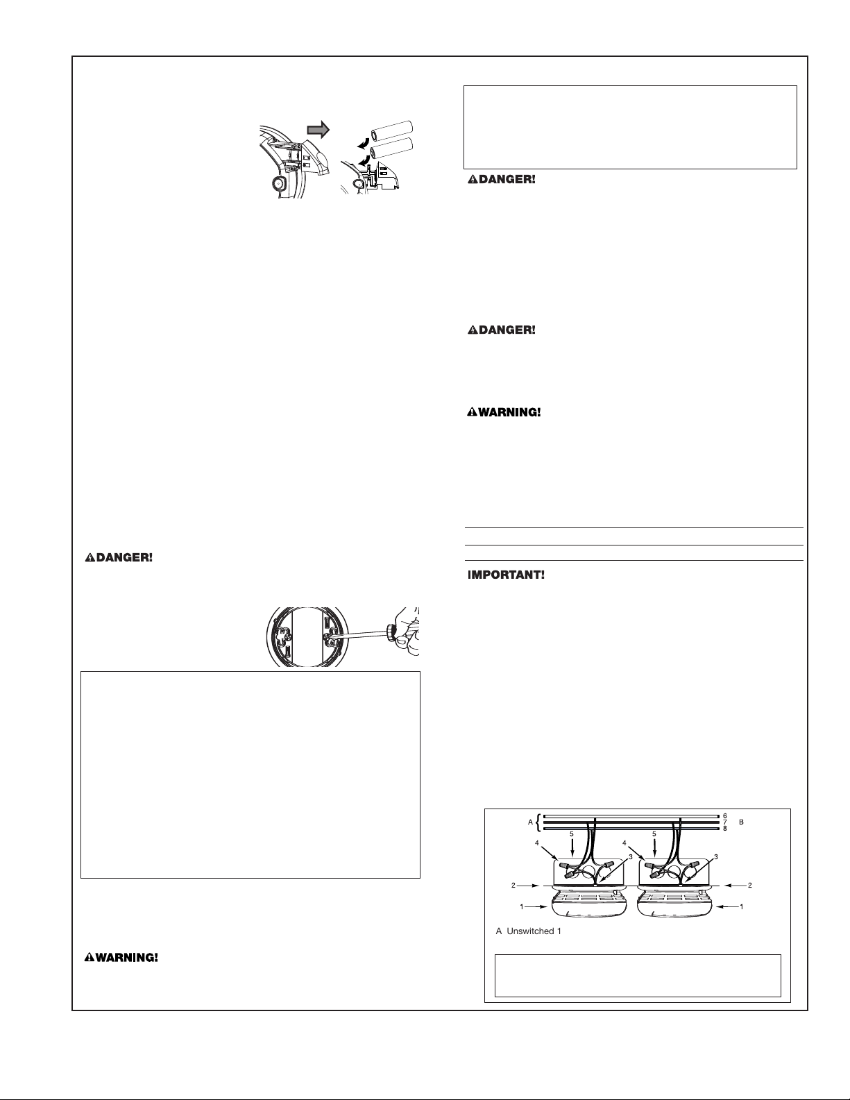
5
}
A
}
B
8
7
6
3
11
2
2
3
4 4
5
A.
Unswitched 120V
AC
60 Hz source
B. To additional units; Maximum = 18 total
(Maximum 12 Smoke Alarms)
1. Smoke Alarm
2. Ceiling or W
all
3.
Power Connector
4. Wir
e Nut
5. Junction Box
6.
Neutral Wir
e (Wht)
7.
Inter
connect Wire
(Orange)
8. Hot Wire (Blk)
QUICK INSTALLATION INSTRUCTIONS
Easily expand an existing inter
connected 120V AC hardwired system by
simply r
eplacing one Alarm in the series with the First Alert
®
ONELINK
TM
Model SA520. Then add additional battery-operated Alarms to expand the
system with no additional electrical work.
1.
Insert the batteries into the battery
drawer of the first Alarm and close
the drawer
.
2.
The Alarm will sound with a chirp.
3. If you purchased the Talking Smoke
and Carbon Monoxide Alarm, you
will now be pr
ompted to set the
Alarm's location. Follow the direction given by the Alarm.
NOTE: Steps 4 through 6 need to be completed within two minutes.
If mor
e than two minutes pass, the Green power LED will stop
blinking. Simply open the battery drawer of the second Alarm
and repeat steps 4 through 6.
4.
Insert the batteries into the battery drawer of the
next Alarm. DO NOT
CLOSE THE DRAWER.
5. Press and hold the test button and then close the battery drawer.
6.
Once you hear the unit chirp, release the test button. The Green power
LED will start to blink indicating the ONELINK
TM
Alarm is waiting for
program data from one of the other setup ONELINK
TM
Alarms.
7.
Press and hold the test button on the first Alarm, until the second Alarm
chirps and its Green power LED stops blinking. Then release the test
button.
8.
If you purchased the Talking Smoke and Carbon Monoxide Alarm, you
will now be prompted to set the Alarm's location. Follow the directions
given by the Alarm.
9.
If you have purchased the hardwired battery back-up ONELINK
TM
Alarm,
you can now connect the hardwired Alarm by installing the three-wire
connector on the ceiling to the Alarm.
10. Repeat steps 4-9 for additional ONELINK
TM
Alarms.
You have now successfully linked your new ONELINK
TM
Alarms.
T
o add additional Alarms at a later time, follow steps 4 through 9.
3
Loading ...
Loading ...
Loading ...