Loading ...
Loading ...
Loading ...
8
. S-U
Read the entire manual before setting up the LIFE FITNESS Upright Lifecycle Exercise Bike.
E P R F D SE3 SI C O
LIFE FITNESS Lifecycle Exercise Bikes with the Discover SE3 or Discover SI consoles require an AC power supply ac-
cording to the electrical confi gurations listed in the chart below.
Supply Voltage Frequency (Hz) Rated Current (Amps)
100
50 / 60 1.6
110
50 / 60 1.6
120
50 / 60 1.6
200
50 / 60 0.8
220
50 / 60 0.8
230
50 / 60 0.8
240+
50 / 60 0.8
Note: Do not modify the plug provided with this product. If the plug does not fi t into an available electrical outlet, have
a proper outlet installed by a qualifi ed electrician.
B P - E C O
The Explore consoles are powered by a rechargeable 6-volt battery. Check the battery by pressing the knob. The
console should beep and light up. The Explore Console will display the Life Fitness logo. If a prompt doesn’t appear,
mount the Upright Lifecycle Exercise Bike and begin pedaling. The console should light up and programming a work-
out should be possible. Pedal for 20 minutes at 50 rpm or faster during a workout for optimum battery charging. The
pedal action during workouts keeps the battery charged. If the Upright Lifecycle Exercise Bike is externally powered,
battery maintenance is automatic and pedaling is not required.
W L F U L E B
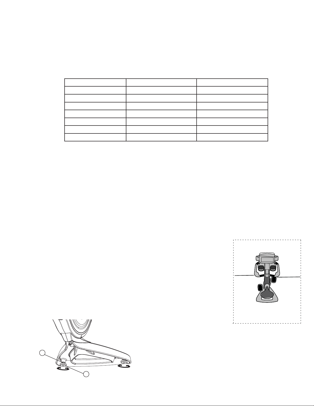
Following all safety instructions in Section 1.1, move the bike to the location in which
it will be used. See Section 4, titled Specifi cations, for the dimensions of the product
footprint (assembled dimensions). Allow a clearance of 2 ft. (0.6 m) in the direction the
bike is accessed from.
H S L F U L E B
After placing the bike in position, check the unit’s stability by attempting to rock it from
side to side. Any slight rocking indicates that the unit must be leveled. Determine which
foot is not resting completely on the fl oor. Loosen the jam nut (A) with an open-end
M17 wrench, and rotate the stabilizing foot (B) to lower it. Verify that the bike is stable,
and repeat the adjustment as necessary until the unit no longer rocks. Lock the adjust-
ment by tightening the jam nut against the stabilizer bar.
A
B
2 ft.
(0.6 m)
2 ft.
(0.6 m)
Loading ...
Loading ...
Loading ...