Loading ...
Loading ...
Loading ...
INSTALLING THE APPLIANCE
(540mm wide product)
Cabinet Requirements
This appliance has been designed to ‘slot-in’ to a 540mm
wide gap built-in standard kitchen cabinets. As such the
appliance can be installed to suit the height and depth
of benches and behind the kick rail of the cabinets. This
allows the cooker to integrate well into contemporary
kitchens. The cooker may also be installed at the end of
a line of benches or with a free space on either side.
• Electric hob models must not be installed in a corner;
they must be installed at least 100mm from the
side wall. Gas hob models must be installed with a
minimum clearance of 100mm to side walls made
of unprotected combustible materials.
• For gas models refer to section 6.10.1 in AS/NZS
5601.1 for all relevant clearances.
WARNING
WARNING
In order to avoid accidental tipping of the appliance (for
example, by a child climbing onto the open oven door),
the anti-tilt plate and stabilising bolt MUST be installed.
Position anti-tilt plate to the rear wall and 25mm from side
of cupboard. Securely fix anti-tilt plate to the floor with
fasteners. Adjust levelling feet on cooker as required.
Stabilising bolt
Stability
bolt
Kick-panel
6.5mm
ø drilled
location hole
Front
adjustable
feet
Remove oven door - to be done by qualified personnel
only. (Refer to procedure).
2. Remove screws from kick panel. To remove kick panel
lift kick panel upwards to release the two location tabs
from the holes in the bottom of the panel.
3. Position cooker into the ant-tilt plate and then mark the
position for the stability bolt hole on the floor.
4. Pull cooker out and drill the bolt hole, using a 6.5mm
masonry or wood drill bit. The bolt hole needs to be
a minimum of 30mm deep when fixing the oven to
concrete.
5. Reposition cooker back into place and fit the stability
bolt through the slot and into the drilled hole.
6. If the cooker is placed on a base, measures must be
taken to prevent the appliance slipping from the base.
WARNING
WARNING
For your safety this cooker is designed to be moved out of
position by a qualified person only.
Installing Splashback
Fit splashback to rear of hob with the two screws provided.
The cooker MUST be installed in compliance with:
• wiring connections in AS/NZS 3000 Wiring Rules
• local regulations, municipal building codes and other
statutory regulations
• For New Zealand Only:
The cooking range must be connected to the supply by
a supply cord fitted with the appropriately rated plug
that is compatible with the socket-outlet fitted to the final
sub-circuit in the fixed wiring that is intended to supply
this cooking range.
Data plate gives information about rating
is located behind the bottom of the oven door
Circuit diagram is located on the back panel of the appliance
• A functional switch MUST be provided near the
appliance in an accessible position (AS/NZS 3000 -
Clause 4.7.1).
• Wiring MUST be protected against mechanical failure
(AS/NZS 3000 - Clause 3.9).
• The cooker requires a means of all pole disconnection
incorporated into the fixed wiring. This MUST have a
disconnection gap of 3mm.
• The cooker MUST be properly earthed.
NOTE: When connections are made to a multi-phase
230/240V supply, the bridge piece MUST be removed
from between the active connections.
TIPS & INFORMATION
TIPS AND INFORMATION
Before you cook in your new oven it is important that
the protective oils used in the manufacture of the product
be removed.
• Make sure that the room is well ventilated (to allow
smoke to escape).
• New appliances can have an odour during first use.
It is recommended to ‘run in’ the oven before cooking
for the first time Operate the oven(s), empty, at a
temperature of 180°C for approximately 30 minutes.
For appliances with a separate grill, run the grill on
maximum for 15 minutes WITH GRILL DOOR OPEN
Please ensure that the room is well ventilated during
this process
CONNECTING TO SERVICES AND COMMISSIONINGWIRING REQUIREMENTS
This appliance must be installed by an authorised person,
according to all codes and regulations of:
• Electrical supply authorities.
• Building regulations.
• Local government and council authorities.
• AS/NZS 5601.1 (particular attention to clause
6.10.1 and figure 6.3 on page 97, and clause
6.10.1.11).
• AS/NZS 3000 (particular attention to clause 4.7.1
and clause 3.9).
Electrical supply connection
• DSP635 models are fitted with a 20-Amp service cord.
• GSP625 and GSP627 models are fitted with a
10-Amp service cord.
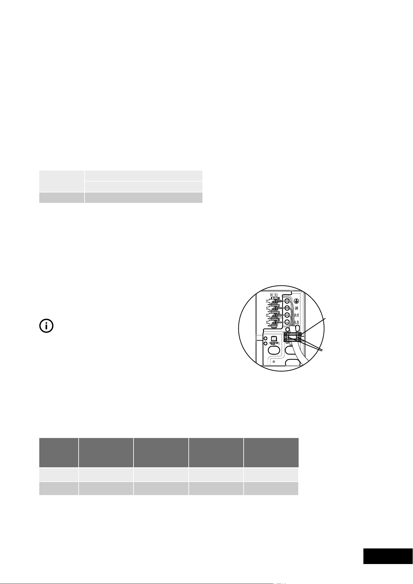
Hard wiring detail (PSP632 models only)
1. Remove terminal cover plate from rear panel of
appliance.
2. Fit wires through hole in cover plate and make
connections to terminals.
3. Engage wires into plastic clip. Secure plastic clip with
two long silver screws (supplied in separate bag).
4. Replace cover plate onto rear panel.
Plastic clips
Plastic clip
securing points
24 25
ACCESSORIES INSTALLATIONACCESSORIESACCESSORIESINSTALLATION
25mm to
side of plate
5mm clearance
Rear cover
Anti-tilt
plate
Rear adjustable foot
MODEL TOTAL WATTAGE
(KW)
TOTAL CURRENT
(AMPS)
CABLE SECTION
(MM2)
MINIMUM
TEMPERATURE
RATING (°C)
WFE642 8.7 36.3 2.5 75
WFE647 10.5 43.8 4.0 75
100mm min.
to combustible
material
600mm min.
to combustible
material
910mm
540mm
630mm
Anti-tilt plate
1.25m electrical
service cord (if fitted)
Clearance
to side wall
(refer notes)
Loading ...
Loading ...
Loading ...