Loading ...
Loading ...
Loading ...
esatto.house 07
Installation Instructions
PAGE 07
It’s important to carefully read the following installation instructions before beginning the installation of your cooktop.
IMPORTANT!
The connection of this cooktop must be carried out by a suitably qualified and licensed person, in
accordance with the current version of the following:
► AS/NZS 3000: 2007 Wiring Regulations
►
2010 Electricity Safety Regulations
► The installation instructions within this user manual
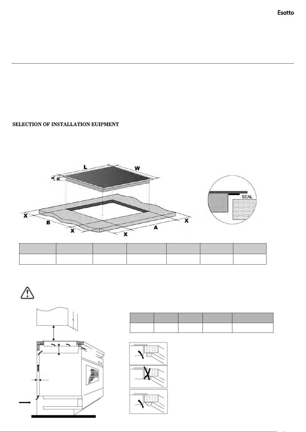
INST
ALLATION INSTRUCTIONS
C
ut
o
ut
t
he
w
ork
s
urface
ac
cording
t
o
t
he
s
izes
s
hown
i
n
t
he
d
rawing .
F
or
t
he
p
urpose
o
f
i
nstallation
an
d
u
se,
a m
inimum
o
f
50
mm
s
pace
s
hall
b
e
p
reserved
ar
ound
t
he
h
ol e.
B
e
s
ure
t
he
t
hickness
o
f
t
he
w
ork
s
urface
i
s
at l
east
30
mm.
P
lease
s
elect
h
eat-resistant
w
ork
s
urface
m
aterial
t
o
av
oid
l
arger
d
eformation
c
aused
b
y
t
he
h
eat
r
adiation
f
rom
t
he
h
otplate.
A
s
s
hown
b
elow
:
L
(mm)
W
(mm)
H
(mm)
D
(mm)
A
(mm)
B
(mm)
X
(mm)
700 520 55 51 560 490 50 mini
U
nder
an
y
c
ircumstances,
m
ake
s
ure
t
he
c
eramic
c
ooker
h
ob
i
s
w
ell
v
entilated
an
d
t
he
ai
r
i
nlet
an
d
o
utlet
ar
e
n
ot
b
locked.
E
nsure
t
he
c
eramic
c
ooker
h
ob
i
s
i
n
g
ood
w
ork
s
tate.
A
s
s
hown
b
elow:
N
ote:
T
he
s
afety
d
istance
b
etween
t
he
h
otplate
an
d
t
he
c
upboard
ab
ove
t
he
h
otplate
s
hould
b
e
at l
east
7
6
0
mm.
USER M ANUAL PAGE 06
SPECIFICATIONS
MODEL PR
560mm × 490mm
MODEL BURNERS OTHER
2
× 1.80 kW radiant zones (Ø 190mm)
2 × 1.20 kW radiant zones (Ø 155mm)
Touch control operation
4
×
Individual residual heat indicators
Framless design
CERAMIC COOKTOP SURFACE LAYOUT
1
2
3
4
Y
OUR INALTO COOKTOP
TOUCH CONTROLS
700mm × 520mm × 55mm
EE70T
EE70T
700
55
490
560
1
2
3
4
1.80kW zone (Ø 190mm)
1.20kW zone (Ø 155mm)
1.80kW zone (Ø 190mm)
1.20kW zone (Ø 155mm)
760 50 mini 20 mini Air intake Air exit 5mm
A1(mm) B1(mm) C1(mm) D1(mm) E1
A1
B1
E1
C1
D1
AS/NZS 3000 Wiring Rules
650mm.
650
Loading ...
Loading ...
Loading ...