Range Hood user manual Whirlpool
INSTALLATION REQUIREMENTS
Tools and Parts
Gather the required tools and parts before starting installation. Read and follow the instructions provided with any tools listed here.
Tools needed
■ Drill
■ 1¹⁄4" (3.0 cm) drill bit
■ ¹⁄8" (3.0 mm) drill bit for pilot holes
■ Pencil
■ Wire stripper or utility knife
■ Tape measure or ruler
■ Caulking gun and weatherproof caulking compound
■ Flat-blade screwdriver
■ Phillips screwdriver
■ Saber or keyhole saw
■ Metal snips
Parts supplied
Remove parts from package. Check that all parts are included.
■ #8-18 x 1" (4.2 mm x 25 mm) flat-head screws (2)
■ #8-18 x 5 /8" (4.2 mm x 16 mm) truss-head screws (4)
■ Drywall anchors (2)
■ Mounting brackets (2)
■ 9 /64" x 13/64" (3.5 mm x 5 mm) T10-head screws (2)
■ TORX®† T10 adapter (1)
■ 31 /4" x 10" (8.3 cm x 25.4 cm) rectangular air transition (1)
■ Rectangular air damper (1)
Parts needed
■ Wall or roof cap with damper to match vent system
■ 3 - UL Listed wire connectors
■ Vent clamps/duct tape as required For 7" (17.8 cm) round vented installations:
■ 7" (17.8 cm) round metal vent system
For 3¹⁄4" x 10" (8.3 cm x 25.4 cm) rectangular vented installations:
■ 3¹⁄4" x 10" (8.3 cm x 25.4 cm) rectangular metal vent system For non-vented (recirculation) installations:
■ Charcoal Filter Kit. For information on ordering, see the “Accessories” section.
IMPORTANT: Observe all governing codes and ordinances.
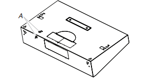
■ It is the installer’s responsibility to comply with installation clearances specified on the model/serial/rating plate. The model/serial/rating plate is located inside the range hood on the left wall.
■ Range hood location should be away from strong draft areas, such as windows, doors, and strong heating vents.
■ Cabinet opening dimensions that are shown must be used. Given dimensions provide minimum clearance. Consult the cooktop/range manufacturer installation instructions before making any cutouts.
■ This range hood is recommended for use with cooktops with a maximum total rating of 55,000 BTUs or less.
■ Grounded electrical outlet is required. See the “Electrical Requirements” section.
■ All openings in ceiling and wall where range hood will be installed must be sealed.
■ These range hoods are factory set for vented installations. Models that are capable of being installed as non-vented (recirculating) require charcoal filters. See the “Accessories” section to order Charcoal Filter Kit.
For Mobile Home Installations
The installation of this range hood must conform to the Manufactured Home Construction Safety Standards, Title 24 CFR, Part 328 (formerly the Federal Standard for Mobile Home Construction and Safety, title 24, HUD, Part 280) or when such standard is not applicable, the standard for Manufactured Home Installation 1982 (Manufactured Home Sites, Communities and Setups) ANSI A225.1/NFPA 501A, or latest edition, or with local codes
Product Dimensions
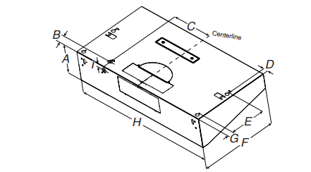
A. 619/54" (16 cm)
B. 2" (5 cm)
C. 825/64" (21.3 cm)
D. 1" (2.54 cm)
E. 832/32" (22.8 cm)
F. 1911/16" (50 cm) G. 11 /2" (3.8 cm)
H. 36" (91.4 cm) for 36" (91.4 cm) models 30" (76.2 cm) for 30" (76.2 cm) models
I. 55/64" (2.2 cm)
Installation Clearances
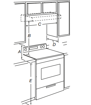
A. 18" (45.7 cm) min. clearance - upper cabinet to countertop
B. 24" (61.0 cm) minimum - bottom of range hood to cooking surface
C. 30" (76.2 cm) min. cabinet opening width for 30" (76.2 cm) models 36" (91.4 cm) min. cabinet opening width for 36" (91.4 cm) models
D. 12" (30.5 cm) minimum cabinet depth
E. 36" (91.4 cm) base cabinet height
Venting Requirements
■ This range hood is factory set to exhaust the air to the outside through the wall or the roof. A non-vented (recirculating) installation will require a Charcoal Filter Kit. See the “Accessories” section for ordering information.
■ Vent system must terminate to the outdoors, except for nonvented (recirculating) installations.
■ Do not terminate the vent system in an attic or other enclosed area.
■ Do not use a 4" (10.2 cm) laundry-type wall cap.
■ Use a 7" (17.8 cm) round metal vent or a 3¹⁄4" x 10" (8.3 cm x 25.4 cm) rectangular metal vent, depending on your installation requirements. Rigid metal vent is recommended. Plastic or metal foil vent is not recommended.
■ The length of vent system and number of elbows should be kept to a minimum to provide efficient performance.
For the most efficient and quiet operation:
■ Use no more than three 90° elbows.
■ Make sure there is a minimum of 24" (61 cm) of straight vent between the elbows if more than 1 elbow is used.
■ Do not install 2 elbows together.
■ Use clamps or duct tape to seal all joints in the vent system.
■ The vent system must have a damper. If roof or wall cap has a damper, do not use damper supplied with the range hood.
■ Use caulking to seal exterior wall or roof opening around the cap.
Cold Weather Installations
An additional backdraft damper should be installed to minimize backward cold air flow and a thermal break should be installed to minimize conduction of outside temperatures as part of the vent system. The damper should be on the cold air side of the thermal break. The break should be as close as possible to where the vent system enters the heated portion of the house.
Makeup Air
Local building codes may require the use of makeup air systems when using ventilation systems greater than specified CFM of air movement. The specified CFM varies from locale to locale. Consult your HVAC professional for specific requirements in your area.
Venting Methods
Vent system can terminate either through the roof or wall. Use 3¹⁄4" x 10" (8.3 cm x 25.4 cm) rectangular with a maximum vent length of 35 ft (10.7 m) or 7" (17.8 cm) or larger round vent with a maximum length of 50 ft (15.2 m) for vent system.
NOTE: Flexible vent is not recommended. Flexible vent creates both back pressure and air turbulence that greatly reduce
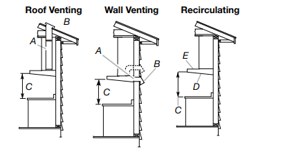
A. 7" (17.8 cm) round vent through roof or 31 ⁄4" x 10" (8.3 cm x 25.4 cm) rectangular vent through the roof or wall (purchased separately)
B. Roof/Wall cap with damper (purchased separately)
C. 24" (61.0 cm) min. above the cooking surface
D. Charcoal Filter Kit (purchased separately)
E. Recirculating grid
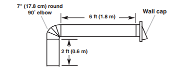
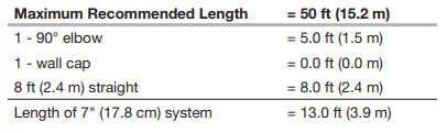
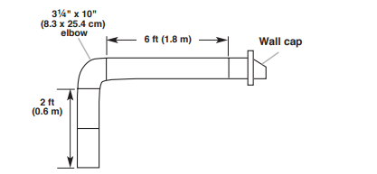
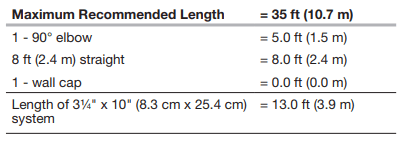
Calculating Vent System Length
To calculate the length of the system you need, add the equivalent feet (meters) for each vent piece used in the system.
7" (17.8 cm) Round Vent System
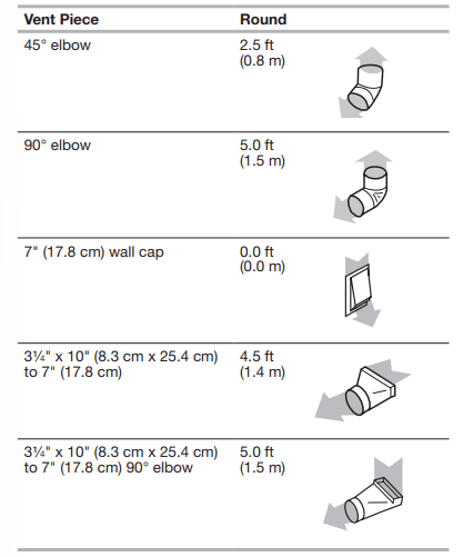
Example vent system
3¹⁄4" x 10" (8.3 cm x 25.4 cm) Vent System
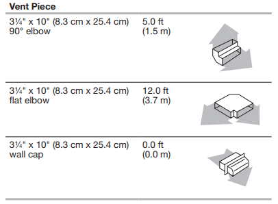
Example vent system
INSTALLATION INSTRUCTIONS
Prepare Location
NOTE: It is recommended that the vent system be installed before hood is installed.
Before making cutouts, make sure there is proper clearance within the ceiling or wall for exhaust vent.
1. Disconnect power.
2. Depending on your model, determine which venting method to use: roof, wall, or non-vented (recirculating).
3. Select a flat surface for assembling the range hood. Place covering over that surface.
4. Lift the range hood and set it upside down onto covered surface.
Determine Wiring Hole Location
Cut only one 1¹⁄4" (3.2 cm) diameter wiring access hole.
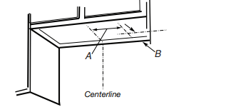
1. Determine and clearly mark a vertical centerline on the wall and cabinet in the area the vent opening will be made.
To wire through top:
1. Mark a line distance “A” from the right of the centerline on the underside of the cabinet. For 12" (30.5 cm) deep cabinets, mark the point on this line that is 2" (5.1 cm) from the back wall. For 15" (38.1 cm) deep cabinets, mark the point on this line that is 5" (12.7 cm) from the back wall. Drill a 1¼" (3.2 cm) diameter hole through the cabinet at this point.
A. 8³⁄8" (21.3 cm)
B. 2" (5.1 cm) for 12" (30.5 cm) deep cabinets* 5" (12.7 cm) for 15" (38.1 cm) deep cabinets* *From wall, not cabinet fram
To wire through wall:
1. Mark a line distance “A” from the right of the centerline on the underside of the wall. Mark the point on this line that is 7 ⁄8" (2.2 cm) from the underside of the cabinet. Drill a 1¹⁄4" (3.2 cm) diameter hole through the rear wall at this point.
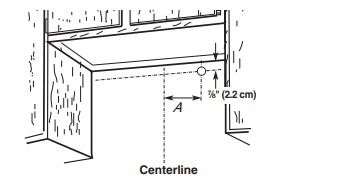
A. 8³⁄8" (21.3 cm)
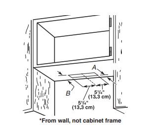
Style 1 - Cut Openings for 3¼" x 10" (8.3 cm x 25.4 cm) Rectangular Vent System
Roof Venting
To make a 4¹⁄4" x 10½" (10.8 cm x 26.7 cm) rectangular cutout on the underside of cabinet top and bottom:
1. Mark lines ¹⁄2" (1.3 cm) and 4³⁄4" (12.1 cm) from the back wall on the centerline of the underside of cabinet.
2. Mark lines 5¼" (13.3 cm) to the right and left of the centerline on the underside of cabinet.
3. Use saber or keyhole saw to cut a rectangular opening for vent.
4. Repeat steps 1-3 for the underside of the top of the cabinet.
A. 1 /2" (1.3 cm)*
B. 43 /4" (12.1 cm)*
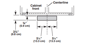
Wall Venting
To make a 3½" x 10½" (8.9 cm x 26.7 cm) rectangle in the wall:
1. Make 2 lines by measuring ³⁄8" (0.9 cm) and 37 ⁄8" (9.8 cm) down from underside of cabinet and mark on the centerline on the back wall.
2. Mark lines 5¼" (13.3 cm) to the right and left of the centerline on the wall.
3.. Use saber or keyhole saw to cut a rectangular opening in the wall for the vent.
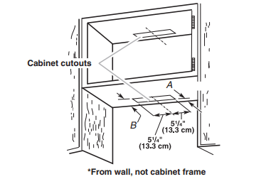
Style 2 - Cut Openings for 3¼" x 10" (8.3 x 25.4 cm) Rectangular Vent to Round Vent Transition
Roof Venting
To make a 4¹⁄4" x 10½" (10.8 cm x 26.7 cm) rectangular cutout on the underside of cabinet bottom:
1. Mark lines ¹⁄2" (1.3 cm) and 4³⁄4" (12.1 cm) from the back wall on the centerline of the underside of cabinet.
2. Mark lines 5¼" (13.3 cm) to the right and left of the centerline on the underside of cabinet.
3. Use saber or keyhole saw to cut a rectangular opening for vent.
A. 1 /2" (1.3 cm)*
B. 43 /4" (12.1 cm)
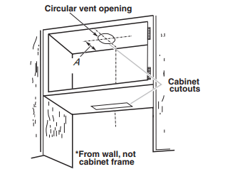
To make a circular vent opening on the underside of the cabinet top:
1. Mark a centerline on the underside of the top of cabinet.
2. Mark a line 5" (12.7 cm) from the back wall on the underside of the top of cabinet.
3. Use a compass or a circle template to draw a circle with a diameter that is ¼" (0.64 cm) larger than the vent.
4. Use saber or keyhole saw to cut the circular vent opening.
Style 3 - Cut Openings for 7" (17.8 cm) Round Vent
To make a circular vent openings on the underside of the cabinet top and bottom:
1. Mark a centerline on the underside of the top of cabinet.
2. Mark a line 5" (12.7 cm) from the back wall on the underside of the top and bottom of cabinet.
3. Use a compass or a circle template to draw a circle with a diameter that is ¼" (0.64 cm) larger than the vent.
4. Use saber or keyhole saw to cut the circular vent opening
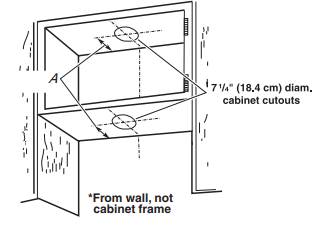
A. 5" (12.7 cm)*
Install Vent System
1. Install vent through the vent opening in upper cabinet or wall. Complete venting system according to the selected venting method. See the “Venting Requirements” section.
2. Use caulking to seal exterior wall or roof opening around the cap.
Prepare Range Hood
Only for venting through the top/wall options:
1. Remove vent knockouts, depending on your installation requirements.
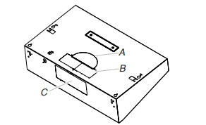
A. Round vent knockout
B. Top rectangular vent knockout
C. Rear rectangular vent knockout
Round vent system installations - Remove top rectangular and round vent knockouts.
Rectangular vent system installations - For roof installations, remove the top rectangular vent knockout. For wall installations, remove the rear rectangular vent knockout.
Non-vent (recirculating) installations - Do not remove any knockouts. 2. Install 7" (17.8 cm) round vent mounting plate or 3¹⁄4" x 10" (8.3 cm x 25.4 cm) vent damper, depending on your vent system installation. Attach to range hood with 3.5 x 9.5 mm screws provided and remove the tape from the damper flap.
NOTE: An optional 7" (17.8 cm) round damper is also available as an accessory. For information on ordering, see the “Accessories” section.
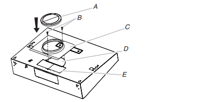
A. 7" (17.8 cm) round damper (See the “Accessories” section)
B. 3.5 x 9.5 mm screws
C. 7" (17.8 cm) round vent mounting plate
D. Round vent knockout
E. Rectangular vent knockout
NOTE: The round vent damper may only be installed on the top of the product.
A. Vertical air transition
B. 3.5 x 9.5 mm screws
C. Vent knockouts
D. Horizontal air transition
Only for recirculating options
For this venting method, it is neccesary to purchase a Charcoal Filter Kit. See the “Accessories” section for ordering.
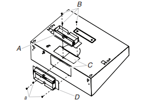
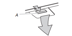
1. Remove each filter by pulling the spring-release handle and then pulling down the filter.
2. Remove the venting method screw from the Vented option with a TORX® T10 screwdriver and set aside.
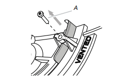
A. Venting method screw
3. Slide the venting lever down as shown in the following image.
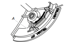
A. Lever on No Vented option
4. Replace the venting method screw on the No Vented (recirculating) option.
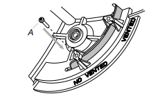
A. No Vented method screw
5. Remove the non-vented (recirculating) vent cover
A. Non-vented (recirculating) vent cover
6. Bend spring clips away from metal grease filter.
7. Place charcoal filter into top side of metal filter
8. Bend spring clips back into place to secure the charcoal filter to the metal filter.
9. Replace metal grease filter
Install Range Hood
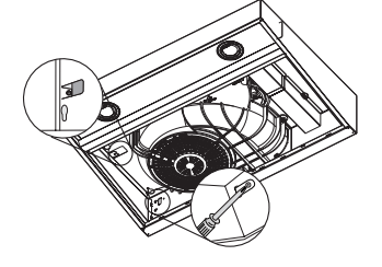
1. Remove the power supply knockout from the top or rear of the vent hood (depending on the incoming location of your home power supply cable) and install a UL Listed or CSA Approved ¹⁄2" strain relief.
A. Power supply knockout
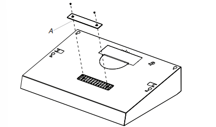
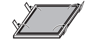
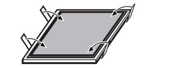
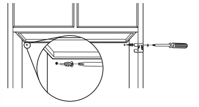
2. Align the exterior edge of the mounting brackets with the exterior edges of the upper cabinet. IMPORTANT: The brackets should touch the upper cabinet. With a pencil, mark the upper holes on the brackets.
3. Using a #2 Phillips screwdriver, install the drywall anchors. Using #8-18 x 1" (4.2 x 25 mm) flat-head #2 Phillips screws, install the mounting brackets using the upper holes.
NOTE: For installation to a surface other than drywall, it is recommended that a qualified contractor determine the anchoring method.
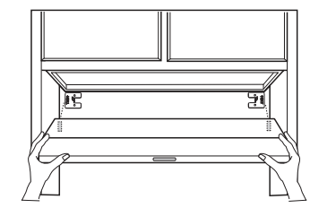
4. Lift the range hood into place and insert the mounting bracket tabs through the slots in the back of the range hood.
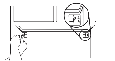
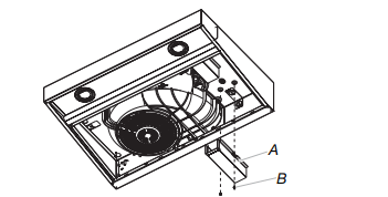
5. From the inside of the range hood, start a #8-18 x 5 ⁄8" (4.2 x 16 mm) truss-head screw into the mounting tab (A) on each side of the range hood as shown in the following inset. Insert the screws approximately 2 turns into the mounting tab holes. Bend each mounting tab upward approximately 45°.
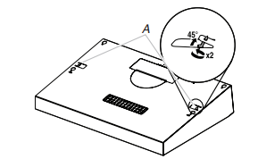
A. Mounting tab
6. Lift the range hood into place, positioning the rear slots over the mounting brackets.
7. Using a Phillips screwdriver, push on the screws that are started into the top mounting tabs and bend the tabs against the cabinet side walls. Attach the screws to the cabinet side walls.
8. For direct wire installations, run the home power supply cable according to the National Electric Code or CSA standards and local codes and ordinances. There must be enough wiring from the fused disconnect (or circuit breaker) box to make the connection in the range hood electrical terminal box.
9. Tighten the strain relief screws.
NOTE: Do not reconnect power until the installation is complete.
OPTIONAL: If you prefer, bend the rear tabs against the rear of the range hood and attach to the wall using #8-18 x 5 /8" (4.2 x 16 mm) truss-head screws.
Connect Vent System
Connect the ventwork to the range hood. Seal joints with vent clamps or duct tape to make secure and airtight. Check that the backdraft dampers work properly.
Power Supply Cable Installation
1. For direct wire installations, run the home power supply cable according to the National Electric Code or CSA standards and local codes and ordinances. There must be enough wiring from the fused disconnect (or circuit breaker) box to make the connection in the hood electrical terminal box. For optional power supply cord kit (see the “Accessories” section), follow the instructions in the “Make Electrical Connections” section.
NOTES:
■ Use only with range hood cord connection kits that have been investigated and found acceptable for use with this model range hood.
■ Do not reconnect power until the installation is complete.
2. Remove the screw from the terminal box cover. Remove terminal box cover and set aside.
A. Terminal box cover
B. Screw
Make Electrical Connection
Option 1 - Direct Wire Installations
1. Disconnect power
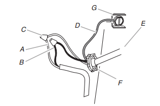
A. White wires
B. Black wires
C. UL Listed wire connector
D. Green (or bare) ground wire
E. Home power supply cable or power cord accessory kit
F. UL Listed or CSA Approved ½" strain relief
G. Green ground screw
2. Use UL Listed wire connectors and connect white wires (A) together.
3. Use UL Listed wire connectors and connect black wires (B) together.
4. Connect green (or bare) ground wire from power supply to green ground screw in terminal box and securely tighten.
5. Install terminal box cover.
6. Reconnect power.
Option 2 - Power Cord Kit Installations
For optional power cord kit installations, follow the instructions supplied with the power cord kit. See the “Accessories” section for information on ordering.
NOTE: Use only with range hood cord connection kits that have been investigated and found acceptable for use with this model range hood.
Complete Installation
1. Replace grease filter if removed. See the “Range Hood Care” section.
2. Check the operation of the range hood fan and light. See the “Range Hood Use” section. If range hood does not operate, check to see whether a circuit breaker has tripped or a household fuse has blown. Disconnect power and check wiring connections.
NOTE: To get the most efficient use from your new range hood, read the “Range Hood Use” section.
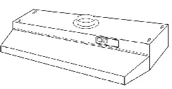
RANGE HOOD USE
The range hood is designed to remove smoke, cooking vapors, and odors from the cooktop area. For best results, start the hood before cooking and allow it to operate several minutes after the cooking is complete to clear all smoke and odors from the kitchen. The hood controls are located on the front panel of the range hood.
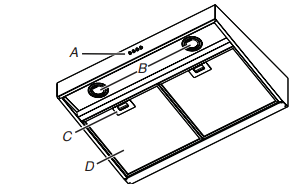
A. Blower and light touch control
B. LED lamps
C. Filter retainer
D. Grease filte
Range Hood Controls
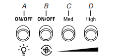
A. Light On/Off button
B. Blower On/Off and minimum speed button
C. Blower medium speed button
D. Blower maximum speed button
Operating the light
The Light On/Off button controls both lights. Press once for ON and again for OFF.
Operating the blower
The blower buttons turn the blower on/off and control the blower speed and sound level for quiet operation. The speed can be changed anytime during fan operation by pressing the desired blower speed button. Press the blower On/Off button a second time to turn the blower off.
RANGE HOOD CARE
Cleaning
IMPORTANT: Clean the hood and grease filters frequently according to the following instructions. Replace grease filter before operating hood.
Exterior Surfaces
IMPORTANT: Do not use soap-filled scouring pads, abrasive cleaners, cooktop polishing creme, steel wool, gritty washcloths or paper towels. To avoid damage to the stainless steel, do not use cleaners that contain chlorine.
Cleaning Method:
■ Rub in direction of grain to avoid scratching or damaging the surface.
■ For stainless steel models, Stainless Steel Cleaner and Polish Part Number 31462A (not included): See the “Assistance or Service” section to order.
■ Liquid detergent or all-purpose cleaner: Rinse with clean water and dry with soft, lint-free cloth.
■ Glass cleaner to remove fingerprints. Metal Grease Filter
For vented installations:
1. Remove each filter by pulling the spring-release handle and then pulling down the filter
A. Spring-release handle
2. Wash metal filter as needed in dishwasher or hot detergent solution.
3. Reinstall the filter by making sure the spring-release handles are toward the front. Insert aluminum filter into upper track.
4. Push in spring-release handle.
5. Push up on metal filter and release handle to latch into place.
6. Repeat steps 1-5 for the other filter.
For non-vented (recirculating) installations: The charcoal filter is not washable. It should last up to 6 months with normal use. Replace with Charcoal Filter Kit. See the “Assistance or Service” section for information on ordering.
Replacing an LED Lamp
The LED lights are replaceable by a service technician only. See the “Warranty” section for service contact information