
Vent Systems
164D4290P339 49-80183 02-03 JR
JVB37
JVB67
Owner’s Manual
& Installation
Instructions
www.GEAppliances.com
Downdraft
Write the model and serial
numbers here:
Model #______________________
Serial # ______________________
You can find them on a label on
the side of the blower housing.
Safety Instructions . . . . . . .2, 3, 7
Operating Instructions
Cooking Tips . . . . . . . . . . . . . . . .5
Raise/Lower Switch . . . . . . . . . . .4
Using the Cooktop . . . . . . . . . . .4
Using the Downdraft System . . .4
Care and Cleaning
Grease Filters . . . . . . . . . . . . . . . .5
Painted or Metal Surfaces . . . . . .5
Stainless Steel Surfaces . . . . . . . .5
Installation Instructions
Advance Planning . . . . . . . . . .8, 9
Before You Begin . . . . . . . . . . . . .6
30″ Cooktop/Downdraft
Unit JVB37 . . . . . . . . . . . . . . . . .10
36″ Cooktop/Downdraft
Unit JVB67 . . . . . . . . . . . . . . . . .11
Dimensions and Clearances . .7, 8
Ductwork . . . . . . . . . . . . .8, 13, 15
Electrical and Gas Location . . . .8
Installation Possibilities . . . . . . . .9
Installing the Downdraft
Vent System . . . . . . . . . . . . .10–17
Optional Kits . . . . . . . . . . . . . . .17
Power Supply . . . . . . . . . . . . . . .12
Raise/Lower Switch . . . . . . . . . .16
Venting Options . . . . . . . . . . . .14
Troubleshooting Tips . . . . . . .18
Consumer Support
Consumer Support . . . . . . . . . .20
Warranty . . . . . . . . . . . . . . . . . . .19
Operating Instructions Safety InstructionsInstallation InstructionsTroubleshooting Tips
Consumer Support
2
IMPORTANT SAFETY INFORMATION.
READ ALL INSTRUCTIONS BEFORE USING.
WARNING! TO REDUCE THE RISK OF A RANGE TOP GREASE FIRE:
■ Never leave surface units unattended at high
settings. Boilovers cause smoking and greasy
spillovers that may ignite. Heat oils slowly on
low or medium settings.
■ Always turn hood ON when cooking at high
heat or when cooking flaming foods.
■ Clean ventilating fans frequently. Grease should
not be allowed to accumulate on fan or filter.
■ Use proper pan size. Always use cookware
appropriate for the size of the surface element.
SAFETY PRECAUTIONS
PLEASE NOTE: The downdraft vent system you have purchased was designed to be used
with GE, GE Profile and GE Profile Performance cooktops listed in this manual.
WARNING!
For your safety, the information in this manual must be followed to minimize the risk of fire or
explosion, electric shock, or to prevent property damage, personal injury, or loss of life.
A. Use this unit only in the manner intended
by the manufacturer. If you have questions,
contact the manufacturer.
B. Before servicing or cleaning unit, switch power
off at service panel and lock the service
disconnecting means to prevent power from
being switched on accidentally. When the service
disconnecting means cannot be locked, securely
fasten a prominent warning device, such as a tag,
to the service panel.
CAUTION:For general ventilating use only.
Do not use to exhaust hazardous or explosive materials
and vapors.
■ Installation work and electrical wiring must be
done by qualified person(s) in accordance with
all applicable codes and standards, including
fire-rated construction.
■ Sufficient air is needed for proper combustion
and exhausting of gases through the flue
(chimney) of fuel-burning equipment to prevent
back drafting. Follow the heating equipment
manufacturer’s guideline and safety standards
such as those published by the National Fire
Protection Association (NFPA), and the
American Society for Heating, Refrigeration
and Air Conditioning Engineers (ASHRAE),
and the local code authorities.
■ When cutting or drilling into wall or ceiling,
do not damage electrical wiring and other
hidden utilities.
■ Ducted fans must always be vented to the
outdoors.
■ To reduce the risk of fire, use only metal
ductwork.
■ PVC sewer pipe can be used as duct under
concrete slab if allowed by local code board.
■ This unit must be grounded.
WARNING: TO REDUCE THE RISK OF FIRE,
ELECTRIC SHOCK, OR INJURY TO PERSONS,
OBSERVE THE FOLLOWING:
Consumer SupportOperating InstructionsSafety Instructions Installation Instructions Troubleshooting Tips
3
www.GEAppliances.com
WARNING! TO REDUCE THE RISK OF A INJURY TO PERSONS IN THE EVENT OF
A RANGE TOP GREASE FIRE, OBSERVE THE FOLLOWING:*
A. SMOTHER FLAMES with a close-fitting lid,
cookie sheet, or metal tray, then turn off the
burner. BE CAREFUL TO PREVENT BURNS.
If the flames do not go out immediately,
EVACULATE AND CALL THE FIRE
DEPARTMENT.
B. NEVER PICK UP A FLAMING PAN—You may
be burned.
C. DO NOT USE WATER, including wet dishcloths
or towels–a violent steam explosion will result.
D. Use an extinguisher ONLY if:
1. You know you have a Class ABC extinguisher,
and you already know how to operate it.
2. The fire is small and contained in the area
where it started.
3. The fire department is being called.
4. You can fight the fire with your back to an exit.
*Based on “Kitchen Fire safety Tips” published by NFPA.
CAUTION:For general ventilating use only.
Do not use to exhaust hazardous or explosive materials
and vapors.
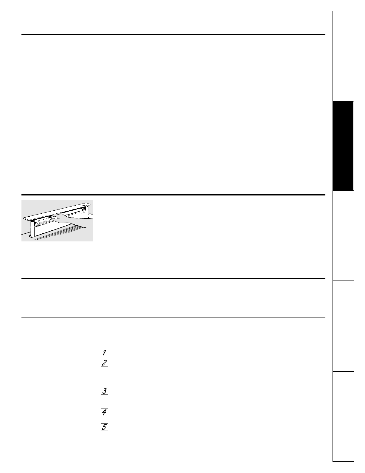
Make sure all fingers are away from the downdraft top
when it is lowered.
If You Need Service…
Do not attempt to repair or replace any part of
the downdraft system unless it is specifically
recommended in this guide. All other servicing
should be referred to a qualified technician.
SAFETY PRECAUTIONS
READ AND FOLLOW THIS SAFETY INFORMATION CAREFULLY.
SAVE THESE INSTRUCTIONS
Be sure electrical power is off before servicing the unit.
It may be necessary to remove the downdraft blower
system in order to service components such as the
blower motor or air vent mechanism.
Disconnect power to the cooktop and remove it
first. Reverse the steps in the Install the Downdraft
section to remove the blower.
Service parts are available from a GE Service and
Parts Center.
SERVICING
4
Using the Cooktop
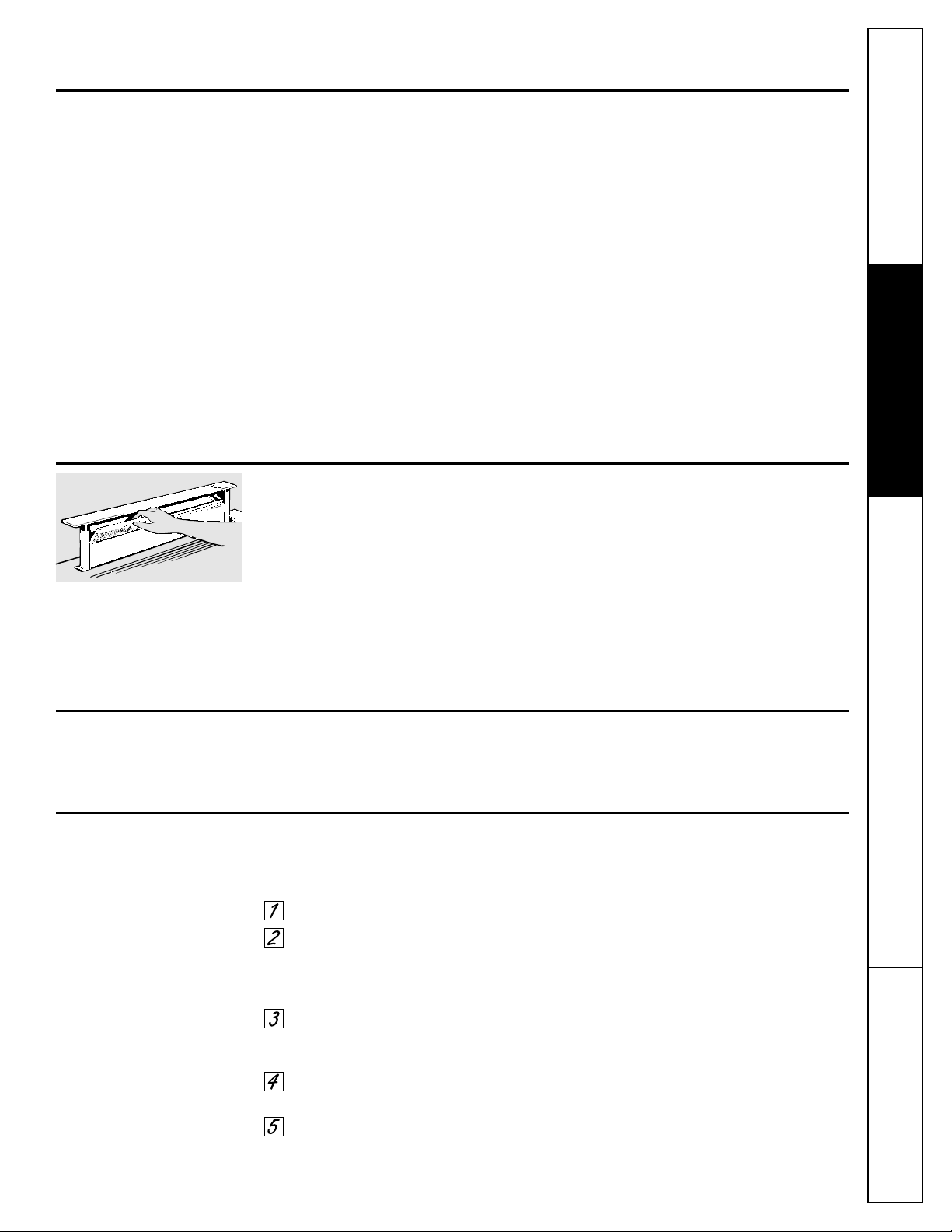
CAUTION: Be careful when raising
or lowering the downdraft. Be sure pots, pot handles
and other objects are clear of the downdraft
and cannot be struck or tipped by the downdraft
being raised.
NOTE: There is a slight trim overhang at each end
of the vent.
■ To avoid injury, be sure fingers are clear
of the downdraft cover when it is being
lowered.
■ Keep hands and fingers away from all
downdraft parts.
Operating Instructions Safety InstructionsInstallation InstructionsTroubleshooting Tips
Consumer Support
Using the downdraft system.
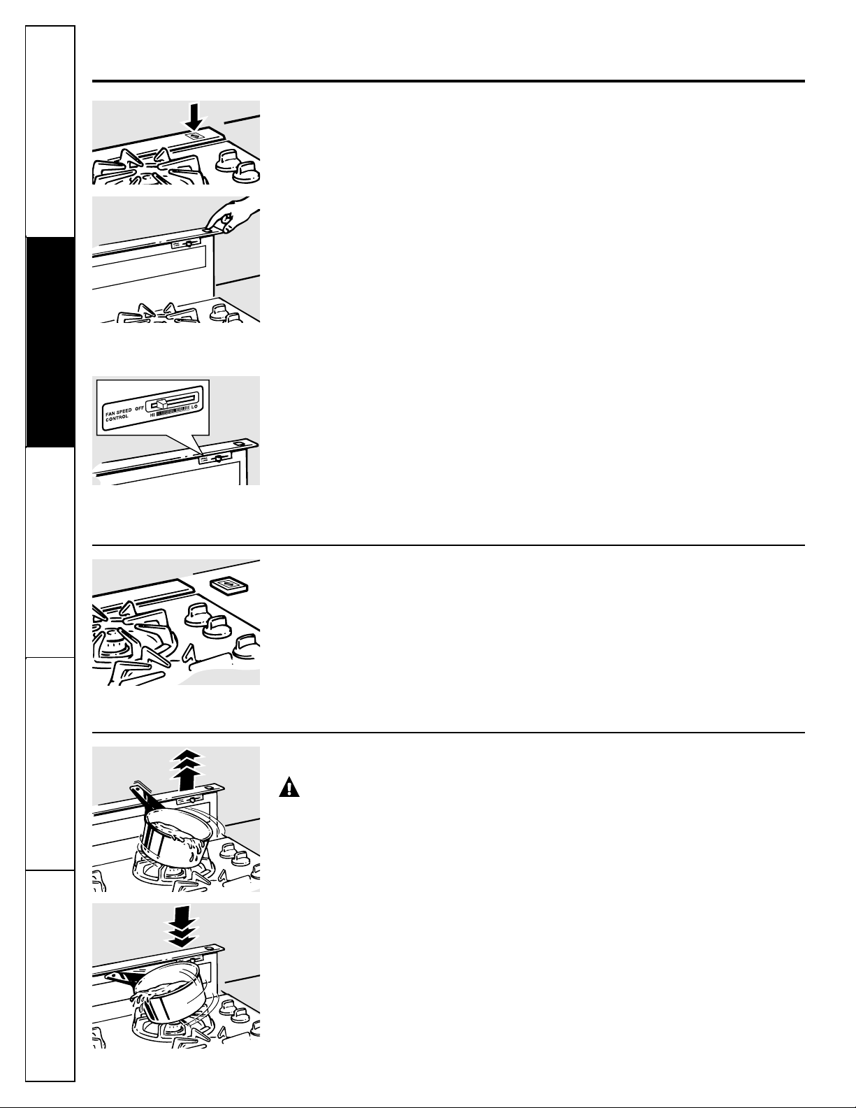
Raise/Lower Switch (30″ models only)
Turn the downdraft blower ON by pressing
the raise/lower switch located at the top
right of the vent. Place your finger on the
“center” of the switch and hold until you
observe the vent moving, then release.
The air vent will rise. Use the selector switch
to turn the blower ON, OFF or to change
the blower speed.
The vent may be lowered by again pressing
the raise/lower switch at the top right side
of the vent. The blower, if left on, will
automatically go off when the vent is
lowered.
NOTE: For most convenient operation, set the
blower to the speed you use most often. The
blower will come on to this speed whenever
the unit is raised.
Remote Raise/Lower Switch (36″ models only)
The 36″ models have a remote raise/lower
switch. It operates in the same manner as
the switch located on the vent. This switch
may be located beside the cooktop or in a
convenient location.
Raise/Lower switch location
may vary.
On some models, the Raise/Lower
switch is located at the top right of
the vent.
Use the selector switch to turn the
blower ON, OFF or to change the
blower speed.
Do not use a steel-wool pad; it will scratch the
surface.
Shake bottle well.
Place a small amount of CERAMA
BRYTE
®
Stainless Steel Appliance
Cleaner on a damp cloth or damp
paper towel.
Clean a small area (approximately
8″ x 8″), rubbing with the grain of the
stainless steel if applicable.
Dry and buff with a clean, dry paper
towel or soft cloth.
Repeat as necessary.
NOTE: If a mineral oil-based stainless steel
appliance cleaner has been used before to
clean the appliance, wash the surface with
dish soap and water prior to using the
CERAMA BRYTE
®
Stainless Steel Appliance
Cleaner. After washing the surface with dish
soap and water, use a generous amount of
CERAMA BRYTE
®
Stainless Steel Appliance
Cleaner to clean the appliance.
To Order
To order CERAMA BRYTE
®
Stainless Steel
Appliance Cleaner, please call our toll-free
number:
National Parts Center 800.626.2002
www.GEAppliances.com
CERAMA BRYTE
®
Stainless Steel Appliance
Cleaner . . . . . . . . . . . . . . . . . . . . . . .# PM10X311
5
Consumer SupportOperating InstructionsSafety Instructions Installation Instructions Troubleshooting Tips
www.GEAppliances.com
Cooking Tips
The high air movement of this downdraft
system can increase the cooking times for
some foods. It may take longer to reach
high cooking temperatures if the downdraft
is turned to high right away. Adjust the fan
speed for best cooking results.
For best results when heating oil for deep
frying or when boiling water, use the front
surface units or wait until the water is
boiling or the oil is at frying temperatures
before turning on the downdraft.
The downdraft may not completely capture all the
steam from pans on the front burners.
Canning
When canning foods in a water-bath canner,
a gentle but steady boil must be maintained
continuously for the required time.
When canning foods in a pressure canner,
the pressure must be maintained
continuously for the required time.
Use of the blower at HIGH speed when
canning may reduce the temperature
enough to stop boiling. While canning,
we recommend using the downdraft at
LOW speed and using the front surface unit.
Painted or Metal Surfaces
Clean greasy surfaces frequently, using
a mild detergent.
Do not use abrasive cloth, steel wool pads or
scouring powder because they will mar the
surface.
Care and cleaning of the downdraft system.
Grease Filters
The efficiency of your downdraft depends
on a clean filter. Frequency of cleaning
depends on the type of cooking you do.
Grease filters should be cleaned at least
once a month. Never operate the downdraft
without the filters in place.
To remove: Pull the filters out by grasping
them and pulling straight up.
To clean: Soak and then agitate in a hot
detergent solution. Light brushing may
be used to remove embedded soil. Rinse,
shake and remove moisture before
replacing.
Filters may also be cleaned in the
dishwasher.
With careful handling, the filter will last for
years. If replacement becomes necessary,
order the part from your dealer.
Stainless Steel Surfaces (on some models)
6
If you have questions, call 800.GE.CARES or visit our Website at: www.GEAppliances.com
REMOVE PACKAGING
Open the carton and remove parts package.
Check contents to be sure all pieces are
present. (The parts package may be attached
to the power cord.)
Remove the shipping materials. Remove the
carton and set aside. The carton can be used
as a pad when changing or adjusting vent
direction.
Installation Downdraft Vent
Instructions System
BEFORE YOU BEGIN
Read these instructions completely and
carefully.
•
IMPORTANT — Save these
instructions for local inspector’s use.
•
IMPORTANT — Observe all
governing codes and ordinances.
• Note to Installer – Be sure to leave these
instructions with the Consumer.
• Note to Consumer – Keep these
instructions for future reference.
• Note – This appliance must be properly
grounded.
• Proper installation is the responsibility of
the installer.
• Product failure due to improper installation
is not covered under the Warranty.
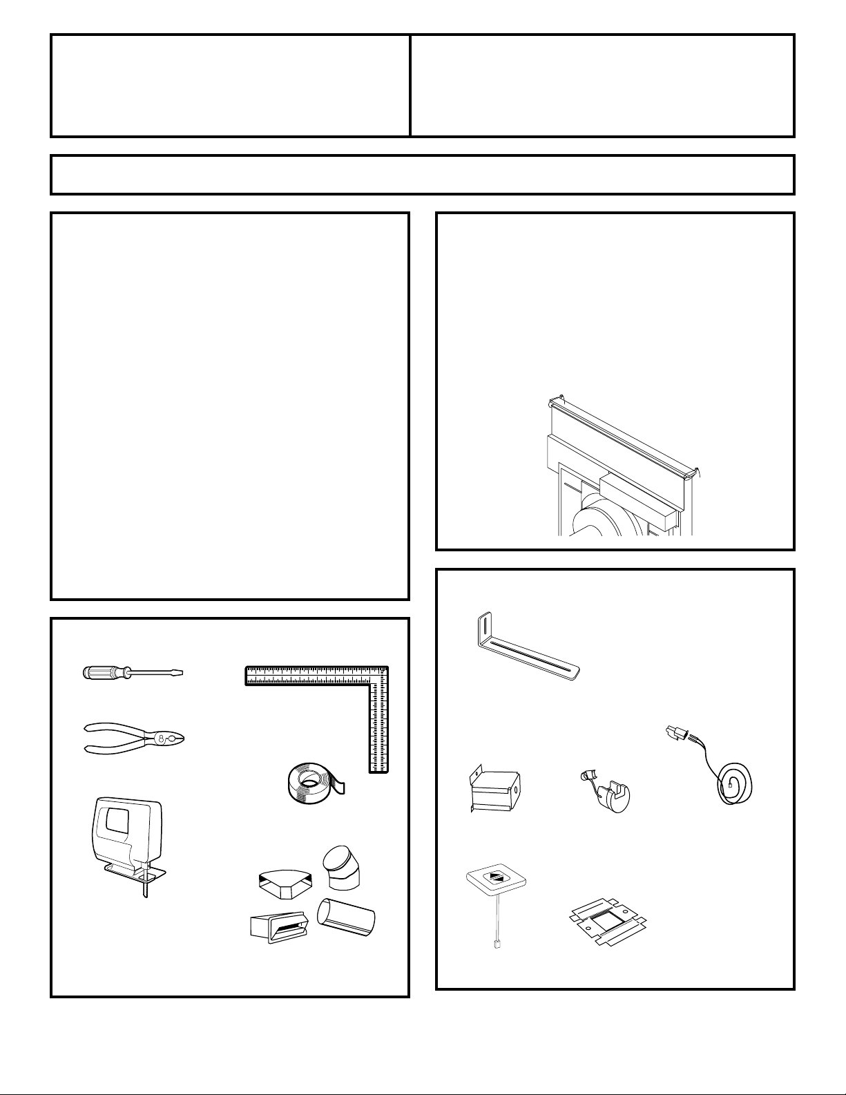
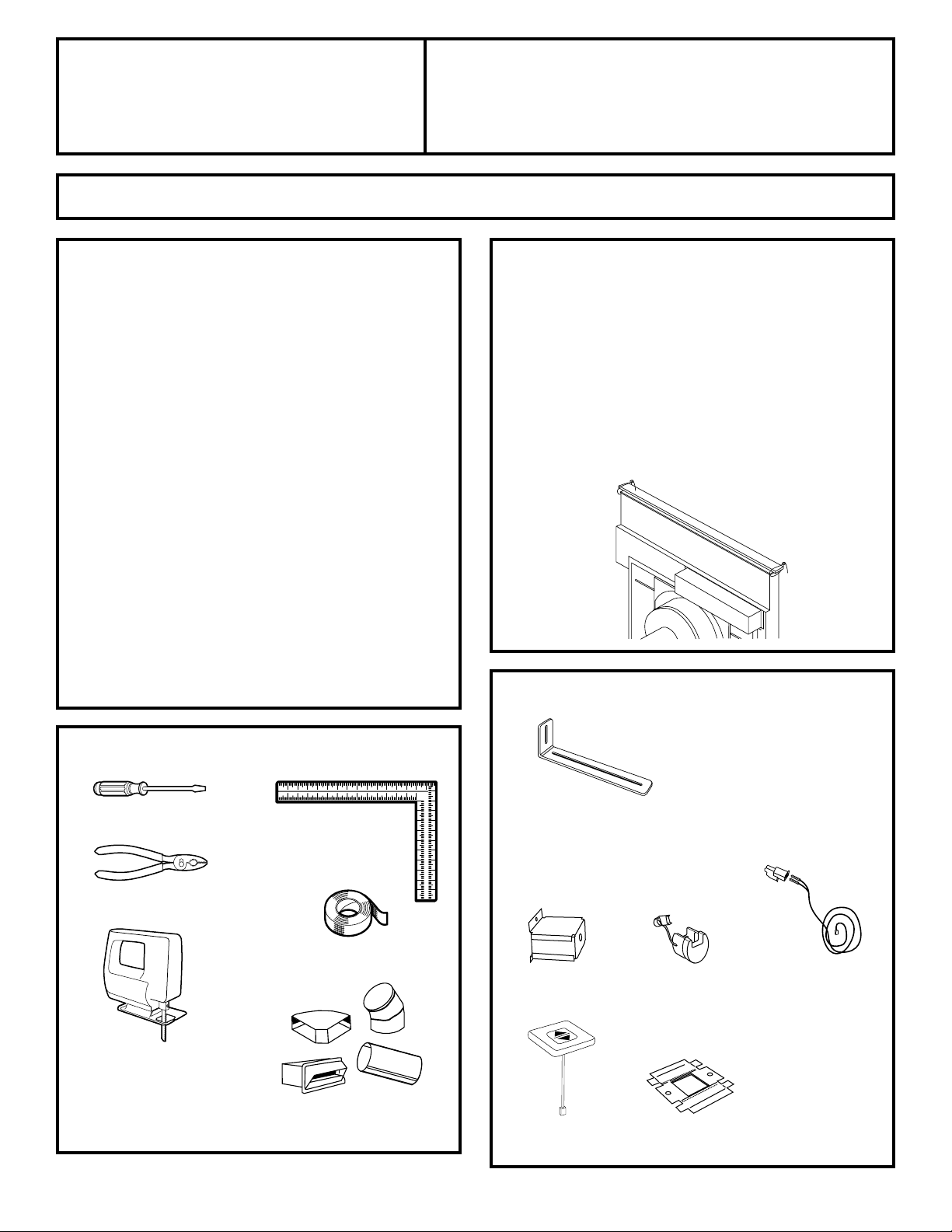
TOOLS YOU WILL NEED
Flat-blade screwdriver
Jig saw
Ductwork to suit
the installation
Carpenter square
PARTS INCLUDED
Remote raise/lower assembly (for 36″ models only)
Stabilizing brackets
(all models) (4)
Wire box (2)
and screws (4)
Plastic strain
relief (2)
Wire and white
connector (1)
Switch cover
plate (1)
Attachment
bracket (1)
Pliers
Duct tape
7
Installation Instructions
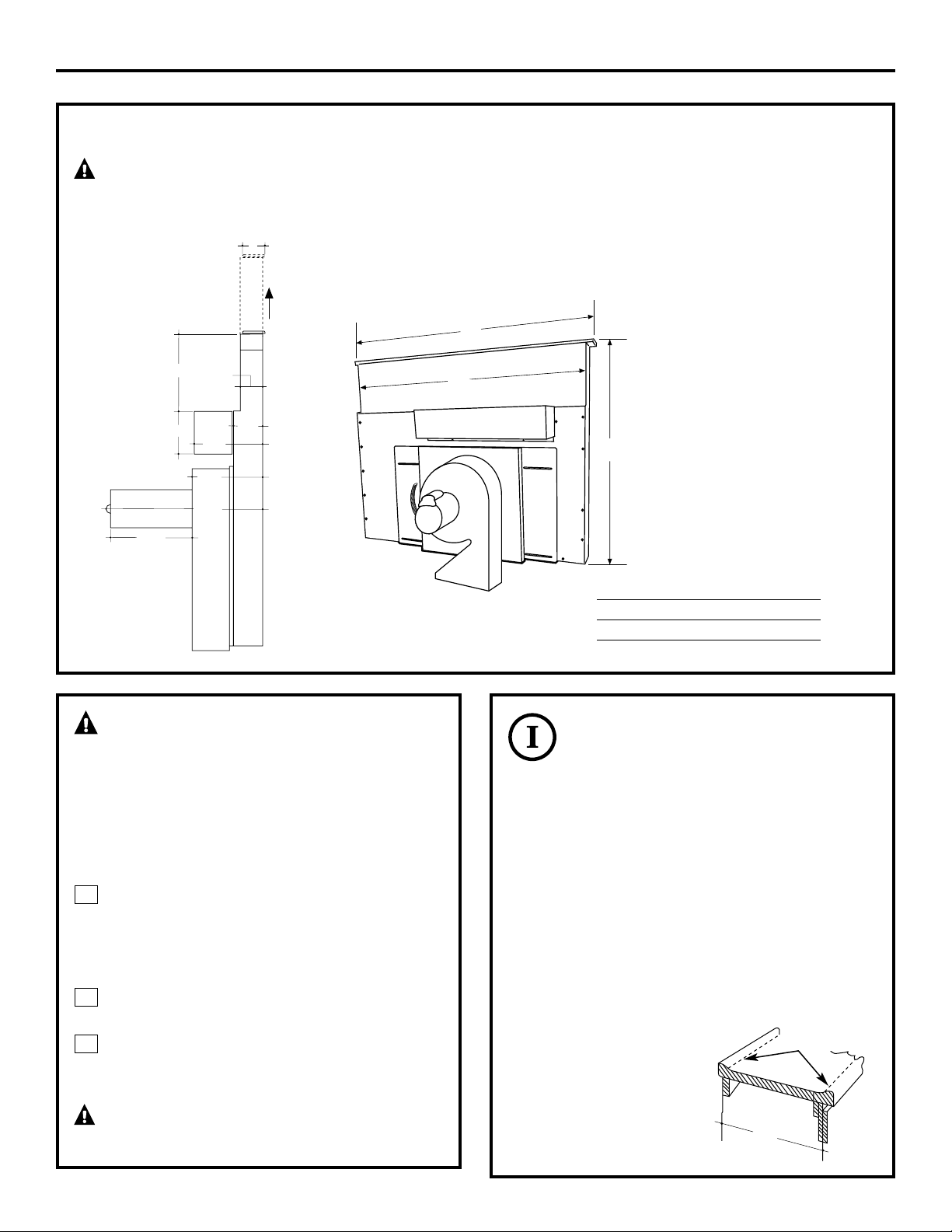
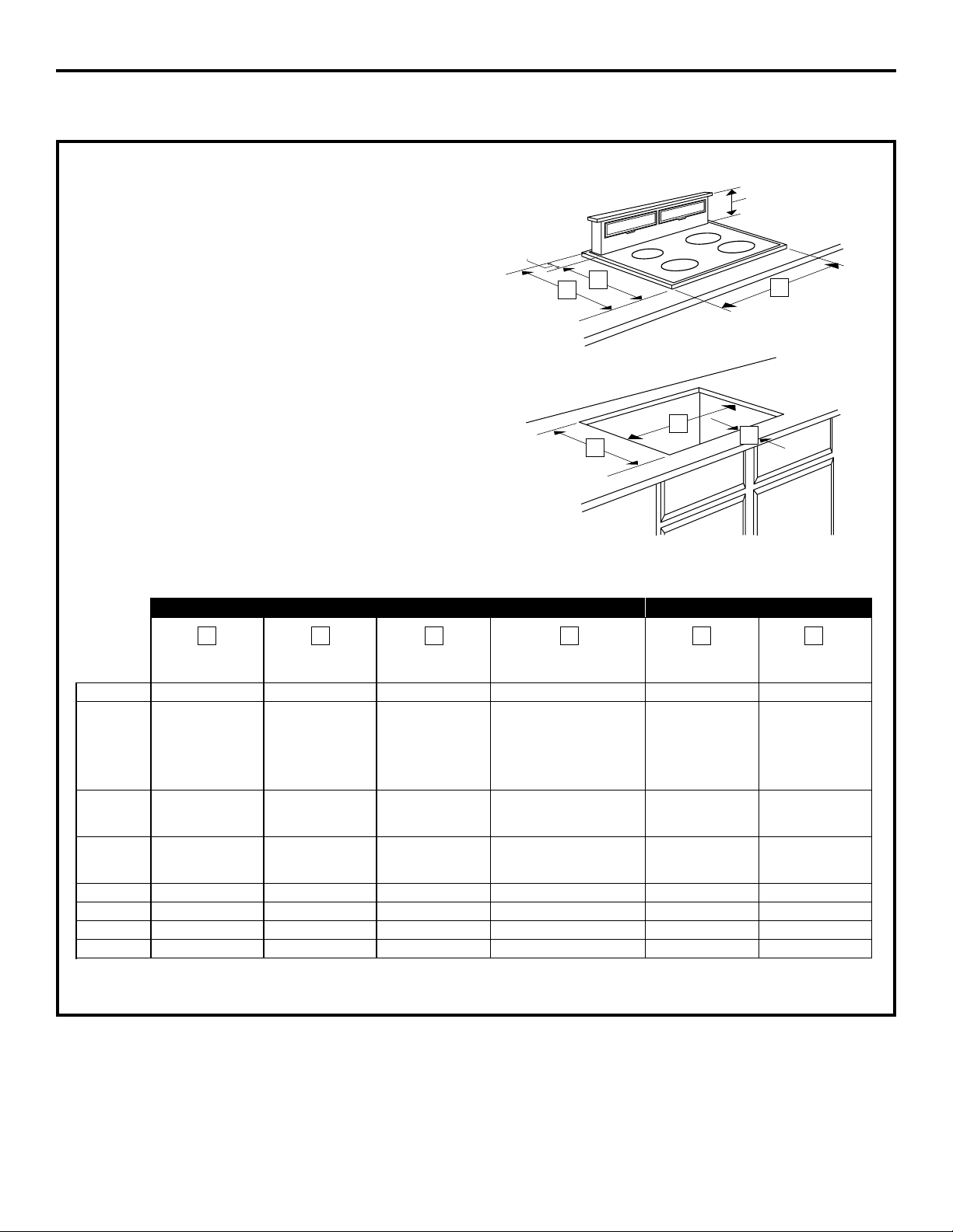
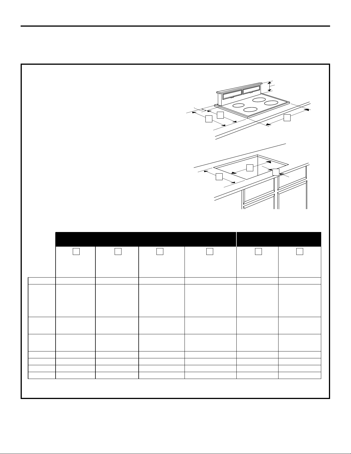
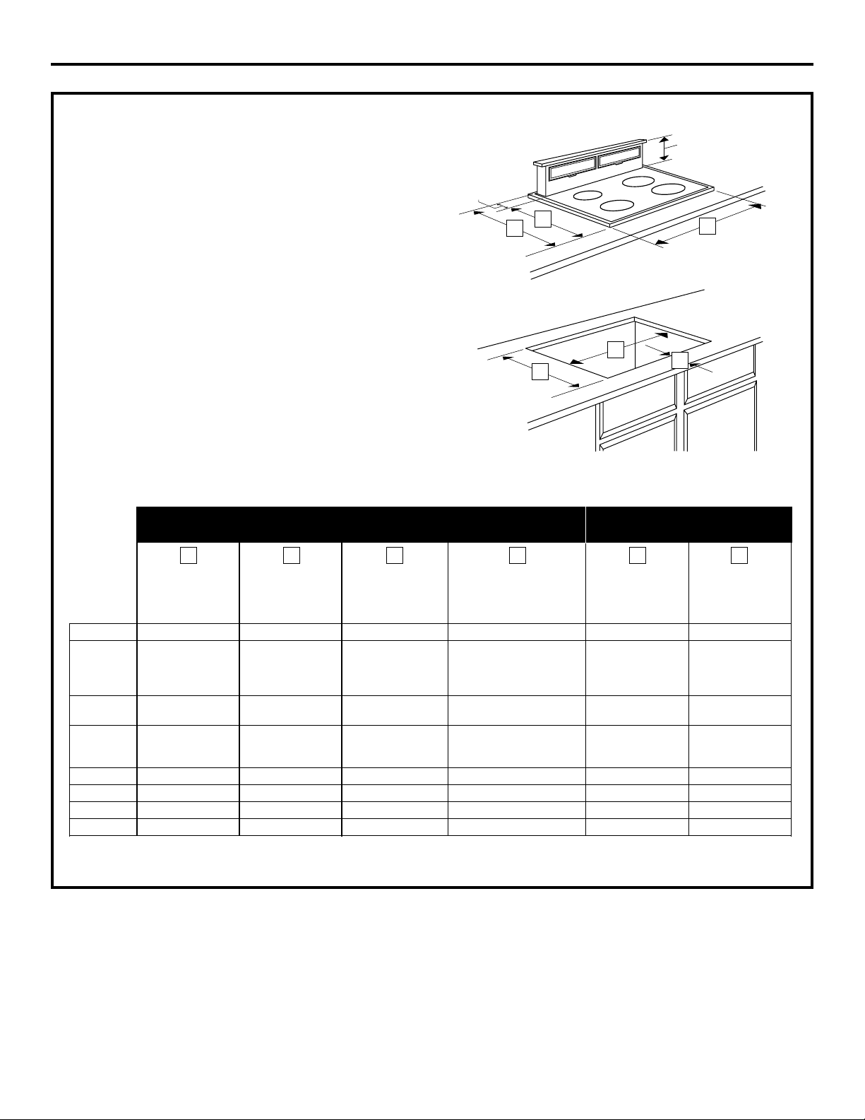
DIMENSIONS AND CLEARANCES
CAUTION — Wall coverings, countertops and
cabinets should withstand 200°F. heat generated by
any cooktop.
AB
30″ Models 30″ 28
1
⁄4″
36″ Models 36″ 33
3
⁄4″
A
B
2″
8
1
⁄2″
3
1
⁄8″
3
3
⁄8″
10
1
⁄2″
7
1
⁄8″
7
1
⁄2″
3
3
⁄4″
2
1
⁄4″
6
1
⁄4″
WARNING!
INSTALLATION SAFETY
INSTRUCTIONS
TO REDUCE THE RISK OF FIRE, ELECTRIC
SHOCK, OR INJURY TO PERSONS, OBSERVE
THE FOLLOWING:
Installation work and electric wiring
must be done by qualified person(s)
in accordance with all applicable codes
and standards, including fire-rated
construction.
Ducted fans must always be vented to
the outdoors.
When cutting or drilling into wall or
ceiling, do not damage electrical wiring
and other hidden utilities.
WARNING — To reduce the risk of
fire, use only metal ductwork.
C
B
A
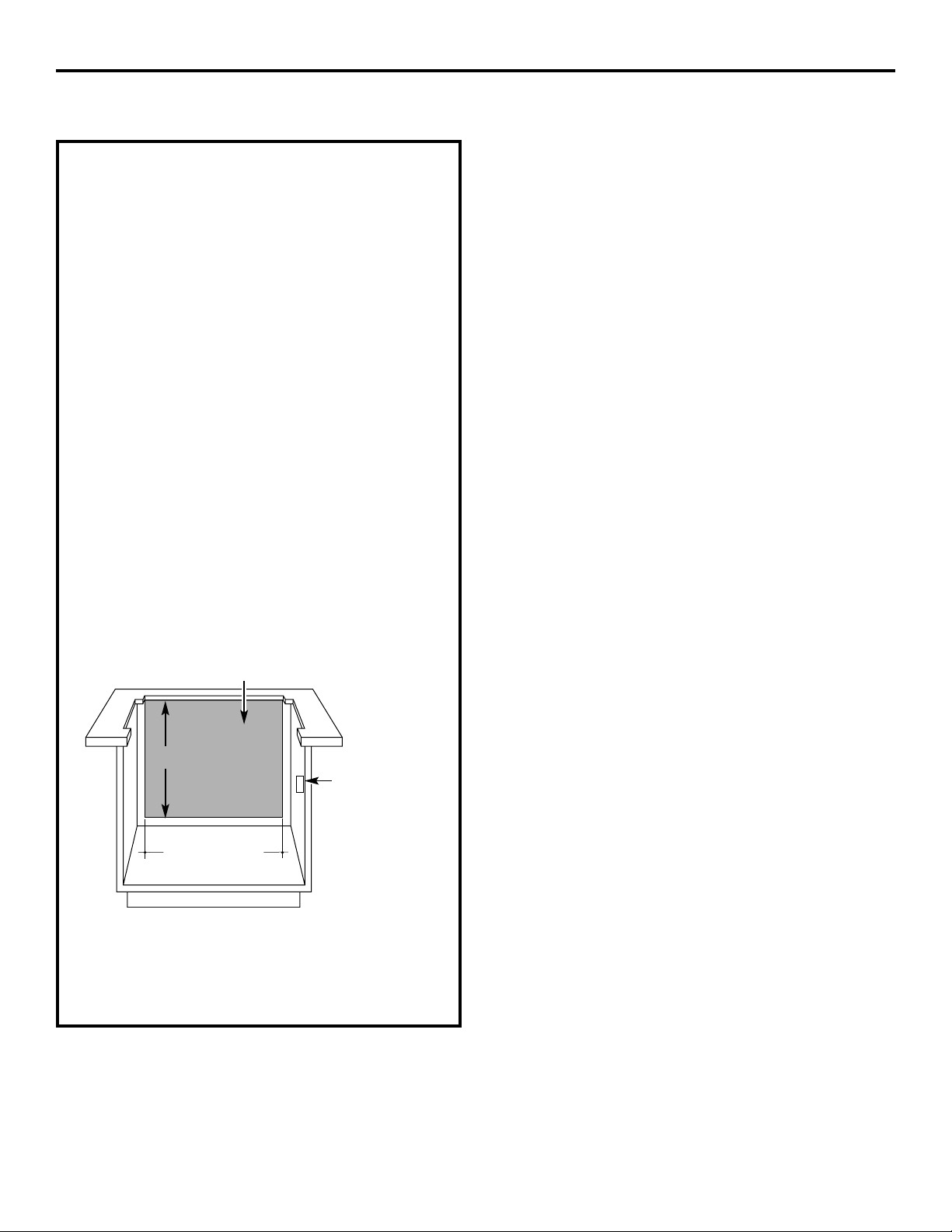
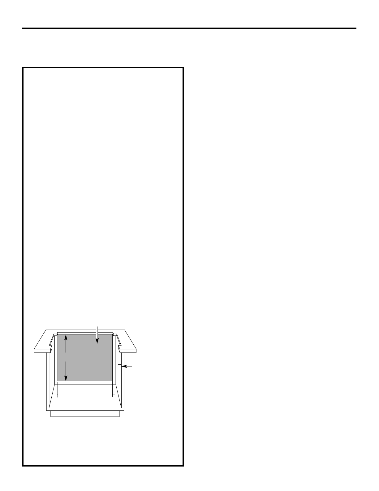
IMPORTANT: These vents are
recommended for island installations.
Against-the-wall installations are
limited due to countertop depth
requirements. The vent and cooktop
combined depth requires an extra
deep flat countertop surface.
The countertop must be at least 26″ deep
with a flat surface area of 23
1
⁄2″ or more, front
to back. (NOTE: JGP932S, JP350SC, JP930SC
and JP938SC require 23
5
⁄8″ flat surface area.)
In addition, other clearances to the front
edge of the countertop must be considered.
• See specific cutout illustrations with your
cooktop model to determine requirements.
• A countertop with
a raised lip or rolled
front edge may not
allow enough flat
area for installation.
Flat surface
area
24″
27″
Installation Instructions
8
ADVANCE PLANNING
DUCTWORK
Prepare ductwork to vent to the outdoors.
• Use the shortest and straightest duct run
possible.
The maximum permissible length for duct
run is 150 feet.
Refer to Duct Fittings chart to calculate
equivalent length for various duct
configurations.
• The downdraft blower system is designed
to use 3
1
⁄4″ x 10″ ductwork. It can be
transitioned to 6″ round.
• Ductwork MUST be vented to the outside—
never into a crawl space, attic or other
enclosed space.
• Determine the need for a wall cap or roof
cap. Purchase the cap in advance from
your home building center or plumbing
supply.
CLEARANCES
• Installation must conform with local codes.
• The downdraft system with blower, motor
and duct work will occupy the cabinet
below the countertop and cooktop.
• The blower/motor assembly can be located
below the cabinet floor. The assembly will
fit between 16″ floor joists.
In this installation a transition to 6 ″ round
is required.
• The blower motor assembly can also be
installed outdoors. Order JXBC67 for
remote blower installations outdoors.
• Refer to Dimensions and Clearances for
information on appropriate placement
and necessary clearances when planning
installation.
• Refer to your specific cooktop installation
instruction for other appropriate clearances.
• Avoid placing cabinetry directly above the
cooking surface when possible.
• If cabinetry is used above the cooking
surface:
Installation must conform with local codes.
Use cabinets no more than 13″ deep.
Maintain 30″ minimum clearance between
cooktop and unprotected cabinets directly
above cooktop.
If clearance is less than 30″, protect cabinet
bottoms with flame-retardant millboard at
least 1/4″ thick or gypsum board at least
3/16″ thick covered with 28 gauge sheet
steel or .02″ thick copper.
Clearance between cooktop and protected
cabinetry must not be less than 24″.
EXCEPTION: Installation of a listed
microwave oven or cooking appliance over
the cooktop shall conform to the installation
instructions packed with that appliance.
• Working areas adjacent to the cooktop
should maintain 18″ minimum clearance
between countertop and cabinet bottom.
COOKTOP ELECTRICAL AND
GAS LOCATION
Plan the placement of the electrical outlet
and gas (if used) carefully. Gas or electrical
outlets cannot be placed on the back wall of
the cabinet because it may interfere with the
downdraft plenum.
Install a standard electrical outlet within
reach of the vents’ 2 foot long power cord.
• The vent and a gas cooktop combination
can operate from the same 120V standard
duplex outlet.
• Electric cooktops must operate from
a separate 240V junction box.
REMOTE SWITCH
(for 36″ models only)
The downdraft vent has a separate
raise/lower switch. Plan to install the switch
in a convenient location outside of the
vent/cooktop cutout.
9
Installation Instructions
Base
cabinet
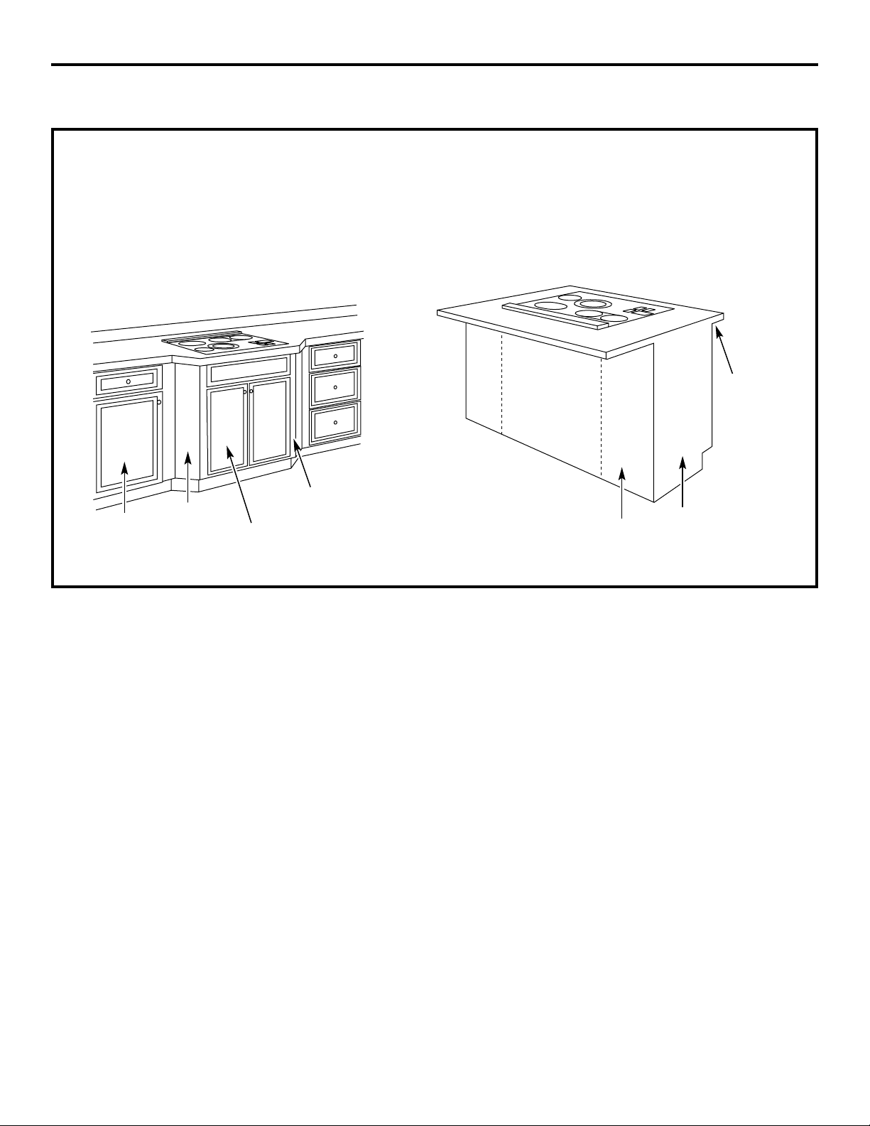
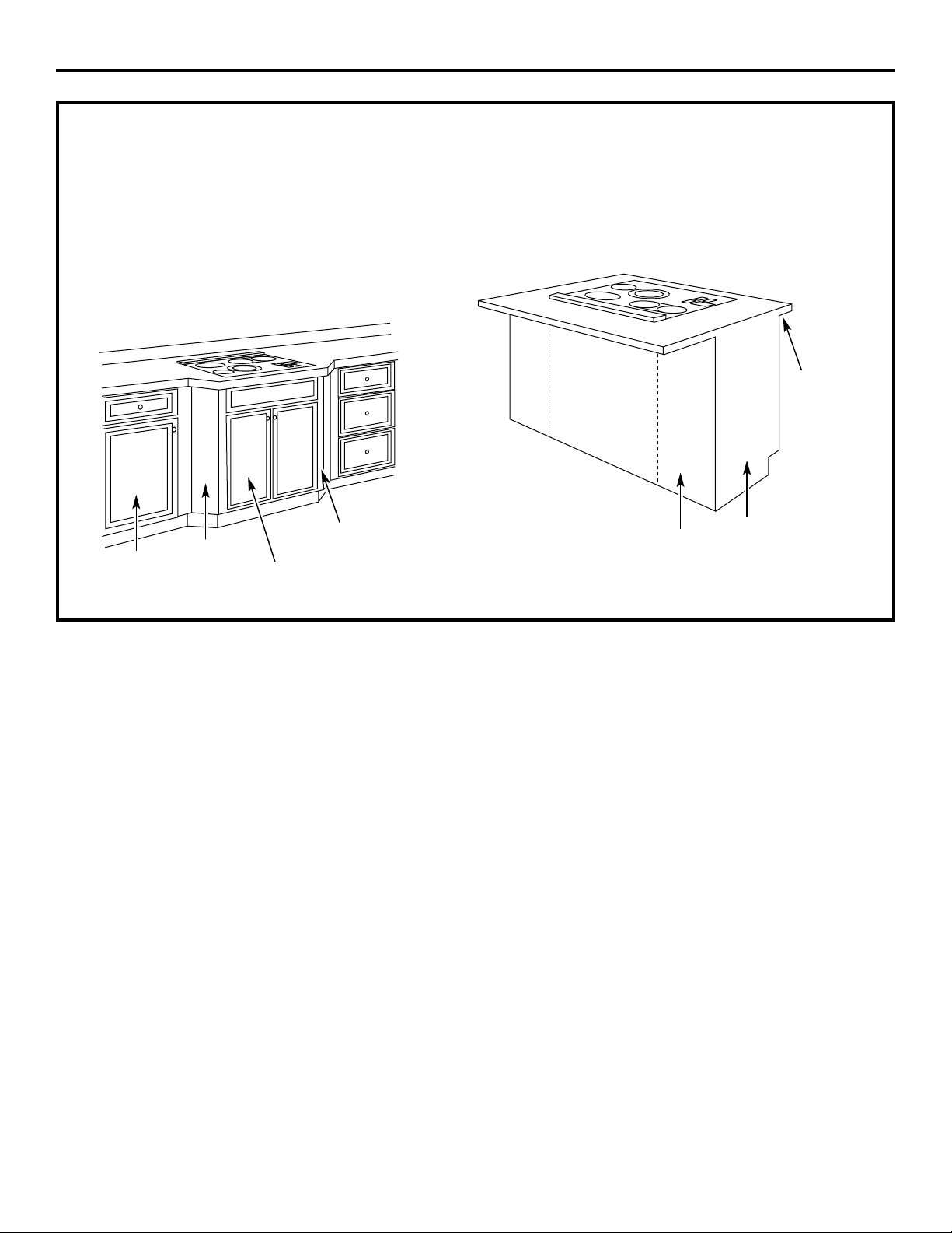
INSTALLATION POSSIBILITIES
When the kitchen design calls for an against
the wall installation, move 24″ deep base
cabinet forward, 3″ to 5″. Filler panels can
be angled or flat to fill the space between
adjacent cabinets.
Maintain cutout clearances to front edge as specified.
In an island or peninsula, the countertop can
be extra deep to provide seating opposite of
the cooktop. Adding base cabinets on each
side of the cooktop provides extra storage
and countertop work space.
Filler
panel
Filler
panel
Base sink
30″ Min. for JVB37
36″ Min. for JVB67
18″
Base to sink
30″ to 42″
Cover
panel
Countertop
overhang
per cooktop
clearances
must be
maintained
End
panel
18″
30″ COOKTOP/DOWNDRAFT
UNIT JVB37
NOTE: Before you begin, measure and mark
Dimension 3 to ensure that adequate flat
countertop surface is available.
Identify the cutout illustration for the cooktop
model you are installing with this downdraft
vent system.
• Draw lines on the countertop to follow
as a cutting guide.
• Make sure sides of the opening are
parallel and rear and front cuts are exactly
perpendicular (right angle) to sides.
Planning Installation 30″ Electric and Gas Cooktops with Downdraft Vents Preparing Cutout
Overall Cooktop Surface Surface Depth Minimum Setback Combined Combined
Model No. Width Overall Depth with Downdraft* Cutout to Front Edge** Cutout Width Cutout Depth
JP326 30-1/4″ 21-1/4″ 23-3/8″ 2-1/2″ 28-1/2″ 22-3/8″
JP340
JP350
29-3/4″ 20-7/8″ 23″ 2-1/2″ 28-1/2″ 22-1/4″
JP930
JP931
JP938
JP939
JP350SC
JP930SC 29-7/8″ 21-1/2″ 23-5/8″ 2-1/2″ 28-1/2″ 22-3/8″
JP938SC
JGP328
JGP933 30″ 21″ 23-1/8″ 2-1/2″ 28-1/2″ 22-3/8″
JGP933S
JGP336 30″ 21″ 23-1/8″ 2-1/2″ 28-1/2″ 22-1/4″
JGP932 29-3/4″ 21″ 23-1/8″ 2-1/2″ 28-1/2″ 22-1/4″
JGP930S 30″ 21-1/4″ 23-3/8″ 2-1/2″ 28-1/2″ 22-1/4″
JGP932S 29-7/8″ 21-5/8″ 23-3/4″ 2-1/2″ 28-1/2″ 22-5/8″
**Includes 1/8″ gap between cooktop and vent trim
**Required to maintain UL or AGA approvals
654321
10
Installation Instructions
INSTALLING THE DOWNDRAFT VENT SYSTEM
2
1
⁄8″
8
1
⁄2″
1
2
3
4
5
6

Planning Installation 36″ Electric and Gas Cooktops with Downdraft Vents Preparing Cutout
Overall Cooktop Surface Surface Depth Minimum Setback Combined Combined
Model No. Width Overall Depth with Downdraft* Cutout to Front Edge** Cutout Width Cutout Depth
JP626 35-1/2″ 21″ 23-1/8″ 2-1/2″ 34″ 21-1/8″
JP960
JP961
JP968
JP969
36″ 20-3/8″ 22-1/2″ 2-1/2″ 34″ 21-3/4″
JP960S
JP968S
36-1/8″ 21″ 23-1/8″ 2-1/2″ 34″ 21-7/8″
JGP628
JGP963 36″ 21″ 23-1/8″ 2-1/2″ 34″ 21-7/8″
JGP963S
JGP636 36″ 21″ 23-1/8″ 2-1/2″ 34″ 21-7/8″
JGP960S 36″ 21-1/4″ 23-1/8″ 2-1/2″ 34″ 22-7/8″
JGP962 36″ 20-7/16″ 22-9/16″ 2-1/2″ 34″ 21-3/4″
JGP962S 36-1/8″ 21-1/16″ 23-3/16″ 2-1/2″ 34″ 22-1/8″
**Includes 1/8″ gap between cooktop and vent trim
**Required to maintain UL or AGA approvals
654321
11
Installation Instructions
36″ COOKTOP/DOWNDRAFT
UNIT JVB67
NOTE: Before you begin, measure and mark
Dimension 3 to ensure that adequate flat
countertop surface is available.
Identify the cutout illustration for the cooktop
model you are installing with this downdraft
vent system.
• Draw lines on the countertop to follow
as a cutting guide.
• Make sure sides of the opening are
parallel and rear and front cuts are
exactly perpendicular to sides.
2
1
⁄8″
8
1
⁄2″
1
2
3
4
5
6
12
Installation Instructions
INSTALLING THE DOWNDRAFT VENT SYSTEM
POWER SUPPLY
This downdraft vent must be supplied with
120V, 60Hz., and connected to an individual,
properly grounded branch circuit, protected
by a 15 or 20 ampere circuit breaker or time
delay fuse.
Gas Cooktops
If this vent is installed in combination with a
gas cooktop, it may operate from the same
duplex outlet.
Electric Cooktops
If this vent is installed in combination with an
electric cooktop, the vent must operate from
a separate 120V outlet.
A properly grounded 3-prong receptacle
should be located within reach of the vents’
2 foot power cord.
• Locate the receptacle inside the cabinet on
the right side wall. The receptacle cannot
be placed on the back of the cabinet wall
where it may interfere with the downdraft
plenum. See illustration.
NOTE: Do not use an extension cord or
adapter plug with this appliance. Follow
National electrical codes or prevailing local
codes and ordinances.
Electrical outlet
12″ above
cabinet floor
34″ for 36″ models
28
1
⁄2″ for 30″ models
Do not leave gas or electrical
connections within shaded area.
29
1
⁄2″
Installation Instructions
13
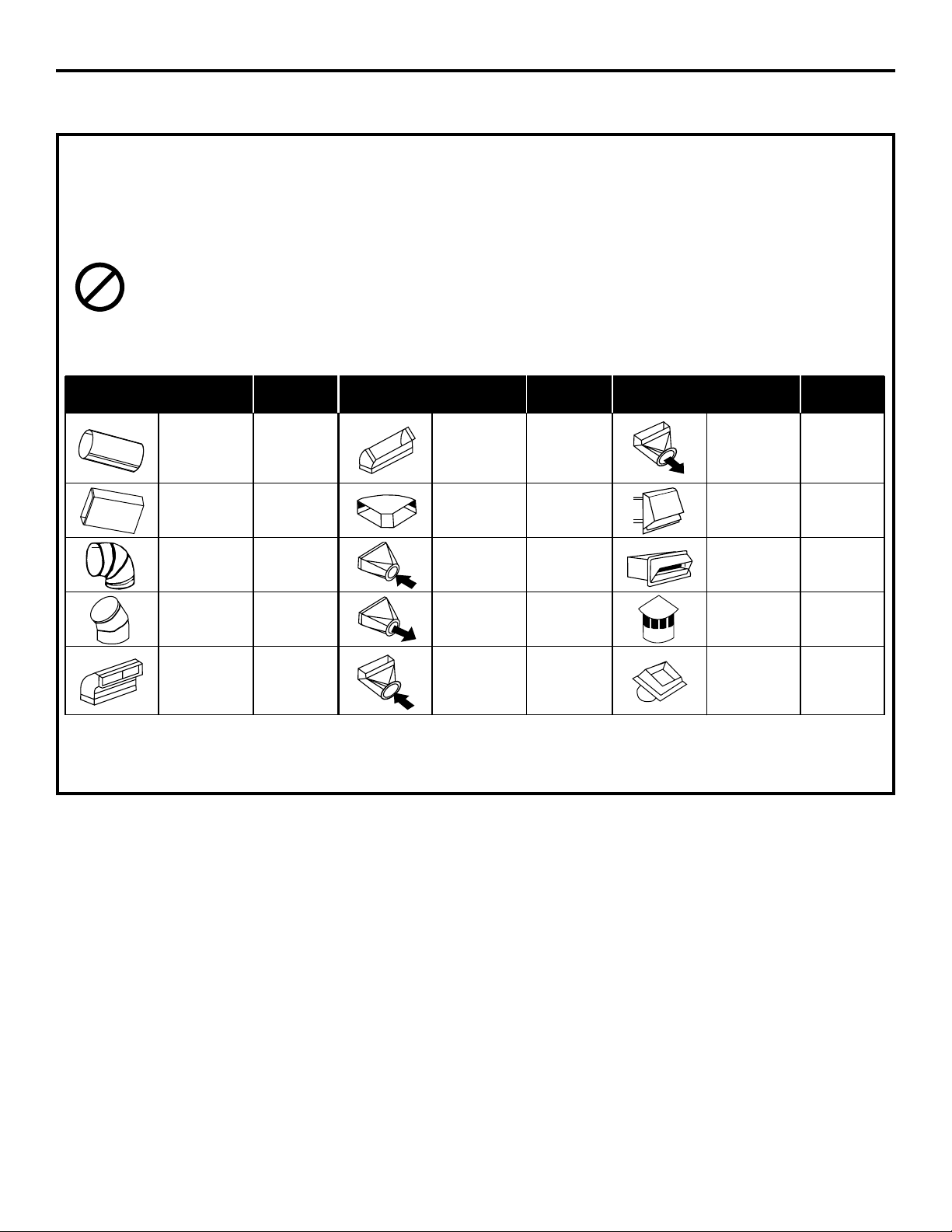
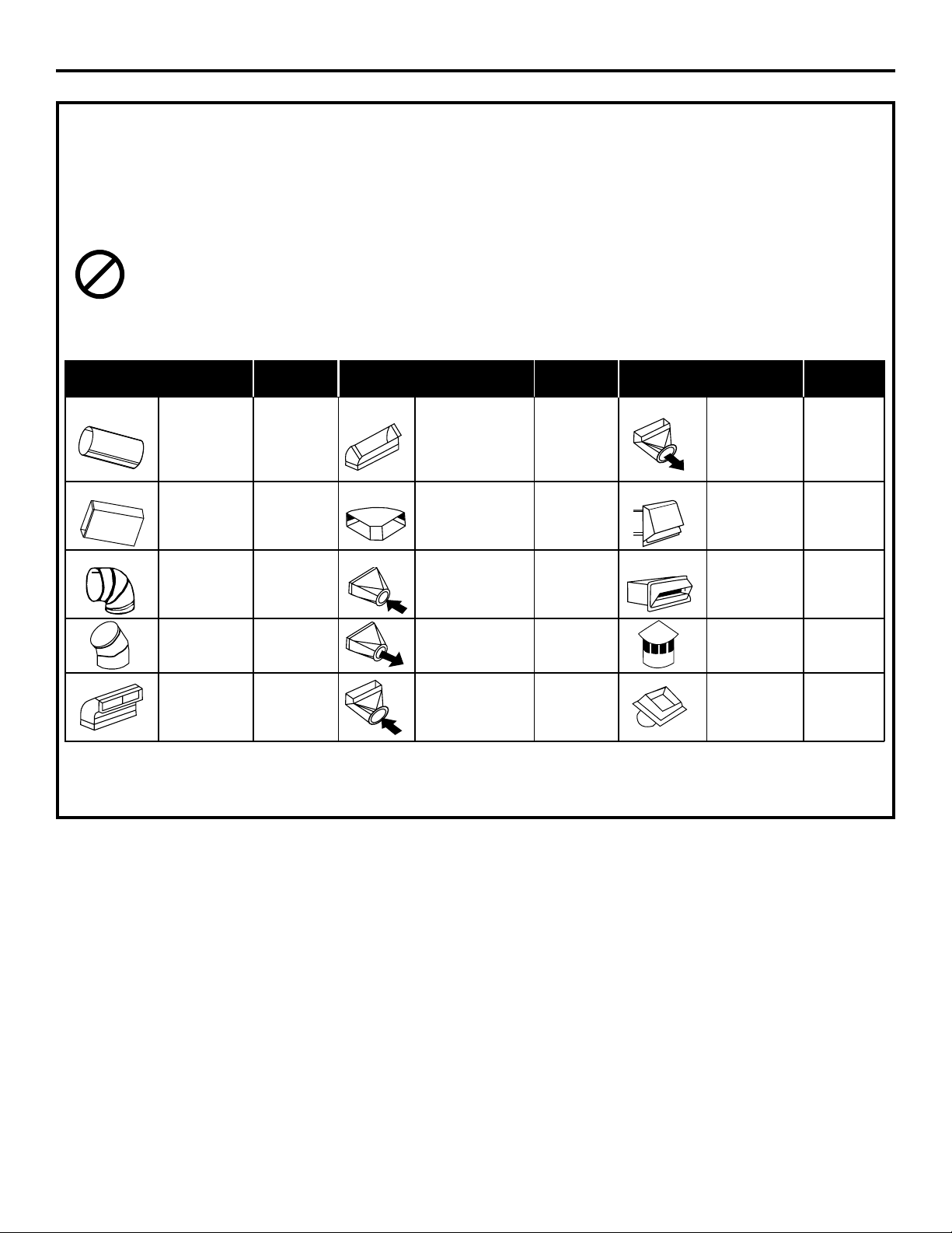
DUCTWORK LENGTH AND DUCT FITTINGS
NOTE: Do not exceed 150 foot maximum permissible equivalent lengths!
Flexible ducting: If flexible metal ducting is used, all equivalent feet values in the table should be
doubled. The flexible metal duct should be straight and smooth and extended as much as possible.
DO NOT use flexible plastic ducting.
Add equivalent lengths for all duct pieces and transitions used to ensure that the duct run does not
exceed the maximum 150 feet.
Duct Equivalent Duct Equivalent Duct Equivalent
Pieces Length* Pieces Length* Pieces Length*
3
1
⁄4″ x 10″
to 6″ Round
6″ Round 1 ft. (per 3
1
⁄4″ x 10″ Transition
12 ft.
Straight foot length) 45° Elbow
5 ft.
90° Elbow
6″ Round
3
1
⁄4″ x 10″ 1 ft. (per 3
1
⁄4″ x 10″ Wall Cap 21 ft.
Straight foot length) 90° Flat Elbow
24 ft.
with Damper
6″ Round 3
1
⁄4″ x 10″
6″ 15 ft. to 3
1
⁄4″ x 10″ 7 ft. Wall Cap 27 ft.
90° Elbow Transition with Damper
3
1
⁄4″ x 10″
6″ to 6″ Round 5 ft. 6″ Round
45° Elbow
9 ft.
Transition Roof Cap
20 ft.
6″ Round
to 3
1
⁄4″ x 10″
3
1
⁄4″ x 10″ Transition
20 ft.
6″ Round
90° Elbow
16 ft.
90° Elbow Roof Vent
24 ft.
SHOULD NOT EXCEED 150 EQUIVALENT FEET
*Equivalent lengths of duct pieces are based on actual tests conducted by GE Evaluation Engineering
and reflect requirements for good venting performance. See chart for CFM Duct Length.
14
Installation Instructions
INSTALLING THE DOWNDRAFT VENT SYSTEM
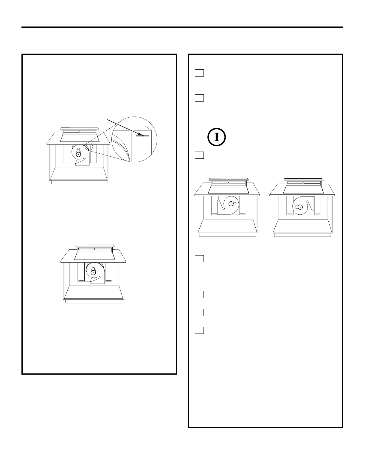
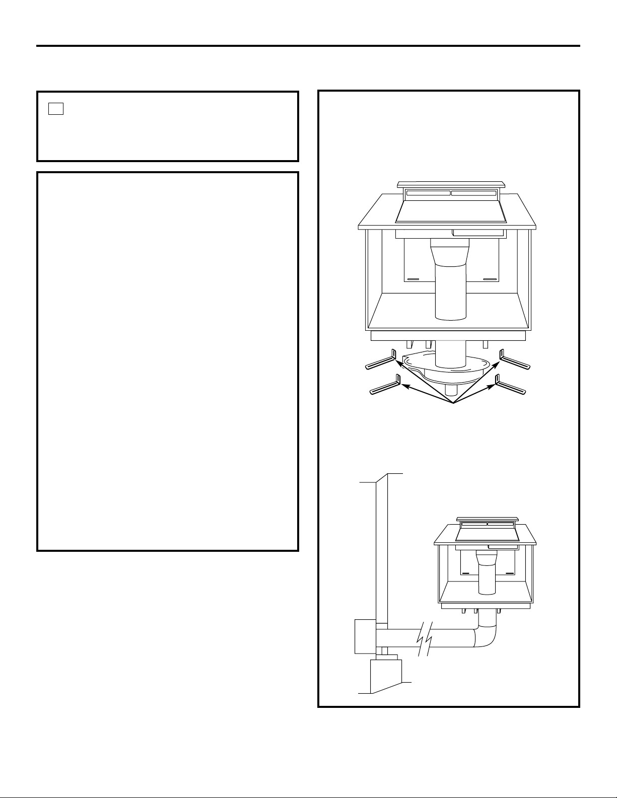
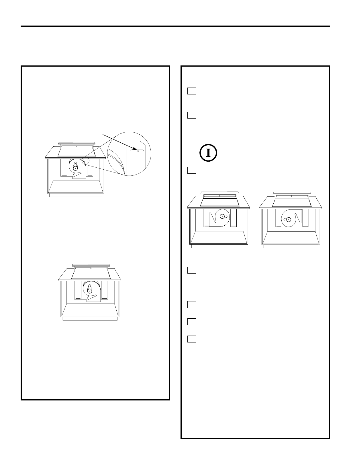
VENTING OPTIONS
Side-to-Side Adjustments
The entire blower mounting plate can be
adjusted 3
1
⁄2″ to the left or right. This will help
to align vent discharge to house ductwork.
Discharge Direction
The blower assembly may be removed and
turned 90° for a left or right side discharge.
• The downdraft vent is shipped with the
discharge outlet pointing straight down
and can be changed to the left or right side.
• A left or right 90° direction adjustment
should be performed before dropping into
the countertop opening.
• Flatten the shipping box to use as a pad.
• Lay the vent on its back onto the pad.
To Change to a Left or Right Discharge
Remove the 4 screws holding the blower
to the mounting plate assembly. Retain
screws.
Remove the blower assembly, turn it
over to access the 4 nuts holding the
blower to the mounting plate. Remove
the nuts.
IMPORTANT: Do not lift the motor
by the power cable.
Turn the blower to the left or right
discharge direction and reinstall the 4
nuts.
Reinstall the blower and mounting plate
with original screws.
To Locate the Ductwork Holes in the Cabinet
Floor or Side Walls
Temporarily, put vent into the countertop
opening.
Push the vent all the way to the back of
the opening.
If you are transitioning to 6″ round,
place transition (obtained locally) over
the discharge outlet.
• Mark the location and remove the
assembly.
• Cut holes and install ductwork
connections.
Order JXRB67 for installation of the blower
and motor below the floor.
Order JXBC67 for installation of the blower
and motor outdoors.
3
2
1
4
3
2
1
Loosen screws to adjust
blower left to right
Discharge down
(as supplied)
Discharge right
Discharge left

15
Installation Instructions
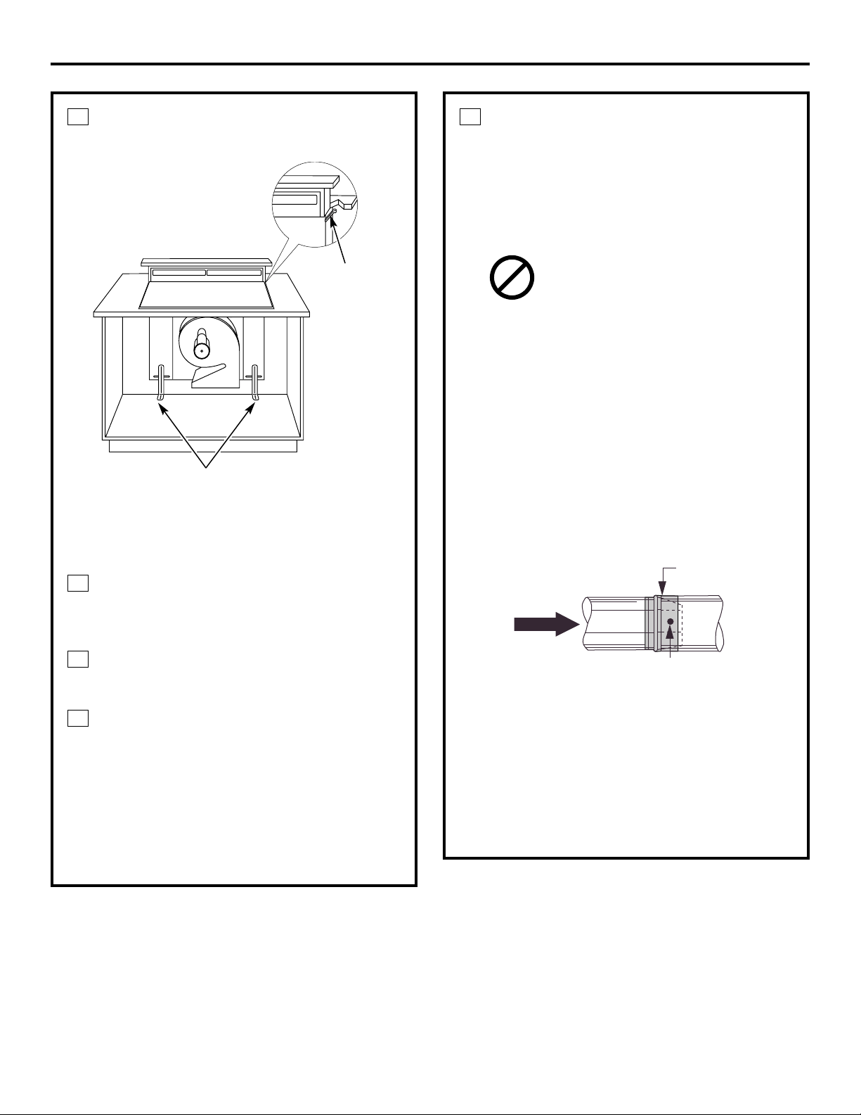
INSTALL THE DUCTWORK
Use minimum 26″ gauge galvanized or
24 gauge aluminum duct 3
1
⁄4″ x 10″ or
6″ round. PVC duct should be used if
installing under a poured concrete slab.
DO NOT USE flexible ducting.
• Always use appropriate roof or wall
cap with damper. Laundry type wall
caps should never be used. See the
Ductwork Length and Duct Fittings
chart.
• Use the straightest duct run possible.
• For satisfactory performance the duct
run should not exceed 150 feet or its
equivalent length when bends or
various fittings are used. Refer to the
table of equivalent lengths to calculate
your installation.
• Install ductwork so the piece of duct
nearest the downdraft unit slots INTO
the next piece of the duct. Secure the
joints with self-tapping screws and
apply duct tape around the joints to
ensure an airtight seal.
2
INSTALL THE DOWNDRAFT VENT
Place the downdraft vent into the
countertop cutout, against the back side.
Secure the downdraft to the countertop
supplied brackets. See illustration.
Fasten 2 brackets to vent side and secure
to cabinet back wall.
Install 2 brackets on the bottom of the
vent. Attach brackets to slide screws on
the vent and to the floor using wood
screws (not supplied).
When installing in a tile countertop
surface, it may be necessary to apply
a locally approved caulking to cover
any gaps.
C
B
A
1
Airflow
Screw
Duct tape over
seam and screw
Secure the lower brackets
to blower housing
Preferred
method
Secure
the upper
brackets
with screws
located on
the side
of case
and attach
to back of
cabinet
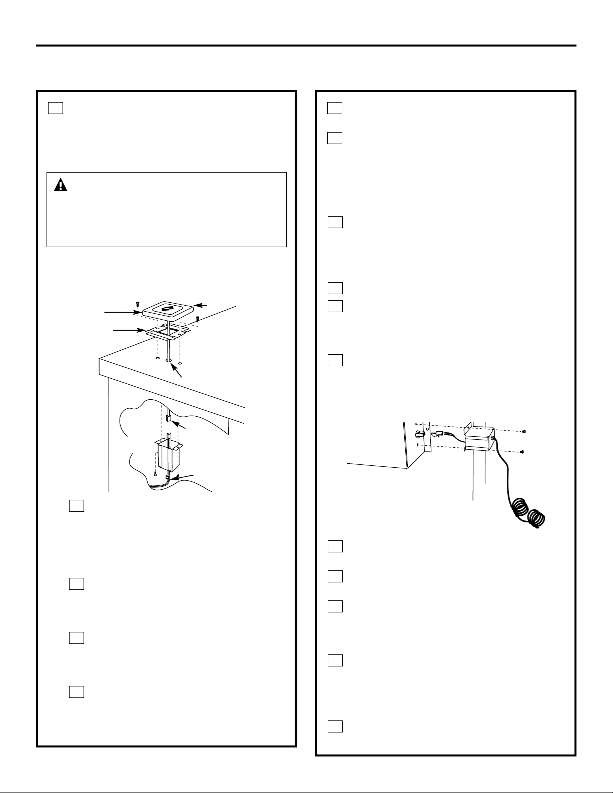
INSTALL THE RAISE/LOWER
SWITCH
NOTE: Step 3 is for 36″ models only.
Skip this step if installing a 30″ model.
NOTE: Determine the location for the
Raise/Lower switch. The wiring lead is
68″ long.
Drill a 3/8″ hole into the desired
location. Use the mounting bracket
as a template to locate the hole
accurately. Check for interference
between the switch cover, adjacent
objects and cooktop/vent overlaps.
If switch is mounted into a tile
surface, drill the hole between tiles.
Use locally approved caulking to
cover any gaps.
Center the mounting bracket over the
hole and mark pilot holes. Remove
and drill holes according to type of
countertop.
Mount the metal switch bracket
with screws (not provided). Choose
screws for your type of countertop
or use locally approved adhesive.
D
C
B
A
3
16
Installation Instructions
INSTALLING THE DOWNDRAFT VENT SYSTEM
WARNING — Disconnect electrical
power from the unit before beginning switch
installation. Failure to do so could result in
personal injury or damage to the electrical
controls.
Remove protective film from the top of
the switch trim.
Peel film from the adhesive strips on the
back of the switch trim. Thread the wire
lead through the mounting bracket and
countertop. Press trim over the mounting
bracket to set the adhesive.
Connect Raise/Lower Wire Lead to Wire Box
Thread wire end with the connector
through the hole on the end of a wire
box. Pull approximately 3″ additional
wire length beyond the open end of
the box.
Connect the mating wire connectors.
Install the wire box onto the bottom of
the countertop or directly behind the
switch. Use screws or adhesive
appropriate for the type of countertop.
Place plastic strain relief over the wire,
just outside of the hole at the end of the
wire box. Do not pinch or twist the wire.
Snap the strain relief closed and press
into the hole.
Connect Wire Lead to Control Box
Thread the long 68″ wire lead through
the end of the other wire box.
Push wire leads into the white connector
provided.
Push wire connector into the mating
connector on the control box. Install the
wire box onto the end of the control box
with screws provided.
Place plastic strain relief over the wire,
just outside of the hole at the end in the
wire box. Do not pinch or twist the wire.
Snap the strain relief closed and press
into the hole.
Coil the excess wire and position away
from moving parts and cabinet contents.
E
D
C
B
A
D
C
B
A
F
E
Trim
Mounting
bracket
3/8″ Hole
Raise/Lower
switch
2 Pin
connector
Strain relief
Pull 3″
length
out of
box
Control box
OPTIONAL KITS
JXRB67 optional accessory for indoor remote
location of the blower/motor assembly. Use
this kit when the blower and motor assembly
will be located below the cabinet floor.
JXBC67 optional outdoor cover accessory
for remote installation of blower and motor
assembly on an outside wall.
17
Installation Instructions
CONNECT THE POWER
Plug power cord into a properly grounded
receptacle.
4
INSTALL THE COOKTOP
• With the downdraft in the “down” position,
place the cooktop into the cutout.
• Push the cooktop back until the back edge
of the cooktop just barely touches the front
edge of the downdraft cover.
• Using a dime as a thickness gauge, align
the cooktop so that there is a minimum
uniform gap of 0.05″ (the thickness of
a dime) between the cooktop and the
downdraft cover.
NOTE: Do not force the downdraft cover to
move rearward when aligning the cooktop.
This may cause the downdraft cover to
impact and damage the cooktop when the
vent is raised and lowered.
NOTES:
• Accurate alignment of cooktop and
downdraft is necessary to ensure that there
is no interference when air vent is raised
and lowered. There should be a gap of
0.05″ (the thickness of a dime) between the
back edge of the cooktop and the front
edge of the downdraft cover.
• Radiant cooktop cannot be flush mounted
when using this downdraft vent.
Mounting
brackets

Operating Instructions Safety InstructionsInstallation InstructionsTroubleshooting Tips
Consumer Support
18
Troubleshooting Tips
Save time and money! Review the chart below first
and you may not need to call for service.
Problem Possible Causes What To Do
Fan does not work The vent is not fully extended. • Press the Raise/Lower switch.
The blower control switch • Slide it to the right.
may be in the OFF position.
Vent does not rise Vent not plugged into an outlet. • Plug vent into a 120V power outlet.
Raise/Lower switch did not • Hold switch down for a couple of seconds to
engage lift motor. activate motor.
Circuit breaker may have • Check circuit breaker. Reset if necessary.
tripped.
Remote switch not plugged in. • Check all connections between the remote switch
and vent body.
Before you call for service…

19
Consumer SupportOperating InstructionsSafety Instructions Installation Instructions Troubleshooting Tips
■ Service trips to your home to teach you how to use
the product.
■ Improper installation, delivery or maintenance.
■ Failure of the product if it is abused, misused,
or used for other than the intended purpose or
used commercially.
■ Replacement of the replaceable filters.
■ Replacement of house fuses or resetting of circuit
breakers.
■ Damage to the product caused by accident, fire, floods
or acts of God.
■ Incidental or consequential damage caused by possible
defects with this appliance.
■ Damage caused after delivery.
What GE Will Not Cover:
This warranty is extended to the original purchaser and any succeeding owner for products purchased for home
use within the USA. In Alaska, the warranty excludes the cost of shipping or service calls to your home.
Some states do not allow the exclusion or limitation of incidental or consequential damages. This warranty gives
you specific legal rights, and you may also have other rights which vary from state to state. To know what your
legal rights are, consult your local or state consumer affairs office or your state’s Attorney General.
If you have an installation problem, contact your dealer or installer. You are responsible for providing adequate
electrical, gas, exhausting and other connecting facilities as described in the Installation Instructions provided
with the product.
Warrantor: General Electric Company. Louisville, KY 40225
For The Period Of: GE Will Replace:
One Year Any part of the downdraft system which fails due to a defect in materials or workmanship.
From the date of the During this full one-year warranty, GE will also provide, free of charge, all labor and in-home
original purchase service to replace the defective part.
GE Downdraft System Warranty.
All warranty service provided by our Factory Service Centers,
or an authorized Customer Care
®
technician. To schedule service,
on-line, 24 hours a day, visit us at www.GEAppliances.com, or
call 800.GE.CARES (800.432.2737).
Staple your receipt here.
Proof of the original purchase
date is needed to obtain service
under the warranty.
Consumer Support.
Printed in the United States
GE Appliances Website www.GEAppliances.com
Have a question or need assistance with your appliance? Try the GE Appliances Website 24 hours a day,
any day of the year! For greater convenience and faster service, you can now download Owner’s Manuals,
order parts, catalogs, or even schedule service on-line. You can also “Ask Our Team of Experts
™
”
your questions, and so much more...
Schedule Service www.GEAppliances.com
Expert GE repair service is only one step away from your door. Get on-line and schedule your service at
your convenience 24 hours any day of the year! Or call 800.GE.CARES (800.432.2737) during normal
business hours.
Real Life Design Studio www.GEAppliances.com
GE supports the Universal Design concept–products, services and environments that can be used by
people of all ages, sizes and capabilities. We recognize the need to design for a wide range of physical and
mental abilities and impairments. For details of GE’s Universal Design applications, including kitchen
design ideas for people with disabilities, check out our Website today. For the hearing impaired, please call
800.TDD.GEAC (800.833.4322).
Extended Warranties www.GEAppliances.com
Purchase a GE extended warranty and learn about special discounts that are available while your warranty
is still in effect. You can purchase it on-line anytime, or call 800.626.2224 during normal business hours.
GE Consumer Home Services will still be there after your warranty expires.
Parts and Accessories www.GEAppliances.com
Individuals qualified to service their own appliances can have parts or accessories sent directly to their homes
(VISA, MasterCard and Discover cards are accepted). Order on-line today, 24 hours every day or by phone
at 800.626.2002 during normal business hours.
Instructions contained in this manual cover procedures to be performed by any user. Other servicing generally
should be referred to qualified service personnel. Caution must be exercised, since improper servicing may cause
unsafe operation.
Contact Us www.GEAppliances.com
If you are not satisfied with the service you receive from GE, contact us on our Website with all the details
including your phone number, or write to: General Manager, Customer Relations
GE Appliances, Appliance Park
Louisville, KY 40225
Register Your Appliance www.GEAppliances.com
Register your new appliance on-line–at your convenience! Timely product registration will allow for
enhanced communication and prompt service under the terms of your warranty, should the need arise.
You may also mail in the pre-printed registration card included in the packing material.
20

Sistemas de
ventilación
164D4290P339 49-80183 02-03 JR
JVB37
JVB67
Manual del
propietario e
instrucciones
de instalación
www.GEAppliances.com
de tiro descendente
Escriba aquí el modelo y
número de serie:
Modelo No. ______________
Serie No. ________________
Puede encontrarlos en una
etiqueta al costado de la caja
del ventilador.
Instrucciones
de seguridad . . . . . .2, 3, 7
Instrucciones de operación
Consejos para cocinar . . .5
Interruptor Raise/Lower
(subir / bajar) . . . . . . . . . .4
Uso de la estufa . . . . . . . .4
Uso del sistema de tiro
descendente . . . . . . . . . . .4
Cuidado y limpieza
Filtros para grasa . . . . . . .5
Superficies de acero
inoxidable . . . . . . . . . . . . .5
Superficies pintadas
o metálicas . . . . . . . . . . . .5
Instrucciones de instalación
Antes de empezar . . . . . . .6
Conductos . . . . . . .8, 13, 15
Dimensiones y
espacios . . . . . . . . . . . . .7, 8
Instalación del sistema
de ventilación
descendente . . . . . . .10–17
Interruptor Raise/Lower
(subir / bajar) . . . . . . . . .16
Kits opcionales . . . . . . . .17
Opciones de
ventilación . . . . . . . . . . . .14
Planificación
anticipada . . . . . . . . . . .8, 9
Posibilidades
de instalación . . . . . . . . . .9
Suministro
de corriente . . . . . . . . . .12
Ubicación de la conexión
eléctrica y de gas . . . . . . . .8
Unidad de estufa / sistema
de tiro descendente de
30″ JVB37 . . . . . . . . . . . .10
Unidad de estufa / sistema
de tiro descendente de
36″ JVB67 . . . . . . . . . . . .11
Consejos para la solución
de problemas . . . . . . . . .18
Apoyo al consumidor
Apoyo al consumidor . . .20
Garantía . . . . . . . . . . . . .19
Operación Seguridad
Instrucciones de
instalación
Solucionar problemasSoporte al consumidor
2
INFORMACIÓN IMPORTANTE DE SEGURIDAD
LEA TODAS LAS INSTRUCCIONES ANTES DEL USO.
¡ADVERTENCIA! PARA REDUCIR EL RIESGO DE UN INCENDIO POR GRASA
DE LA ESTUFA:
■ Nunca deje las unidades de la superficie sin
atención a niveles altos. Los hervores excesivos
causan humo y derramamientos de grasa que se
pueden encender. Caliente el aceite lentamente
en niveles bajo o medio.
■ Sigue encienda la campana cuando cocine con
alto calor o cuando cocine alimentos llameantes.
■ Limpie el mecanismo de ventilación con
frecuencia. No se debe permitir la acumulación
de grasa en el mecanismo de ventilación o filtro.
■ Use el tamaño de sartén adecuado. Siempre use
batería de cocina apropiada para el tamaño del
elemento de la superficie.
PRECAUCIONES DE SEGURIDAD
POR FAVOR TOME EN CUENTA: El sistema de ventilación de tiro descendente que ha
adquirido fue diseñado para uso con estufas GE, GE Profile y GE Profile Performance que
se mencionan en este manual.
¡ADVERTENCIA!
Por su seguridad, se debe seguir la información de este manual para reducir el riesgo de incendio
o explosión, choque eléctrico o para evitar el daño a la propiedad, las lesiones personales o la
pérdida de la vida.
A. Use esta unidad únicamente de la manera
sugerida por el fabricante. Si tiene preguntas,
póngase en contacto con el fabricante.
B. Antes de realizar mantenimiento o limpiar
la unidad, apague la corriente en el panel de
servicio y bloquee el medio de desconexión del
servicio para evitar que la corriente se encienda
de manera accidental. Cuando no se pueda
bloquear el medio de desconexión del servicio,
coloque firmemente un dispositivo prominente
de advertencia, como un letrero, en el panel de
servicio.
PRECAUCIÓN: Úsese para fines de
ventilación general únicamente. No lo utilice para ventilar
materiales peligrosos o explosivos y vapores.
■ El trabajo de instalación y de cableado
eléctrico lo debe realizar una persona calificada
de acuerdo con todos los códigos y normas
correspondientes, incluyendo una construcción
calificada contra incendios.
■ Se necesita suficiente aire para una
combustión y ventilación adecuada de gases
a través del tiro (chimenea) del equipo de
quemado de combustible para evitar un
desfogue descendente posterior. Siga las
pautas y normas de seguridad del fabricante
del equipo calefactor como las publicadas por la
National Fire Protection Association (NFPA), y la
American Society for Heating, Refrigeration and
Air Conditioning Engineers (ASHRAE), y las
autoridades del código local.
■ Al cortar o perforar la pared o el techo, no
dañe el cableado eléctrico y otras conexiones
de servicios públicos ocultas.
■ Los ventiladores de los conductos deben siempre
tener ventilación hacia el exterior.
■ Para reducir el riesgo de incendio, use
únicamente conductos metálicos.
■ Se puede usar tubería de alcantarilla de PVC
como conductos debajo de bloques de concreto
si lo permite la autoridad de códigos locales.
■ Esta unidad debe estar conectada a tierra.
ADVERTENCIA: PARA REDUCIR EL RIESGO DE INCENDIO,
CHOQUE ELÉCTRICO O LESIONES PERSONALES, OBSERVE
LO SIGUIENTE:
Soporte al consumidorOperaciónSeguridad
Instrucciones de
instalación
Solucionar problemas
3
www.GEAppliances.com
¡ADVERTENCIA! PARA REDUCIR EL RIESGO DE UNA LESIÓN A LAS
PERSONAS EN EL EVENTO DE UN INCENDIO POR GRASA
DE LA ESTUFA, OBSERVE LO SIGUIENTE:*
A. SOFOQUE LAS LLAMAS con una tapa que
cierre firmemente, lata de galletas o bandeja
de metal, luego apague el quemador. TENGA
CUIDADO, EVITE LAS QUEMADURAS. Si las
llamas no se apagan de inmediato, EVACUE Y
LLAME A LA ESTACIÓN DE BOMBEROS.
B. NUNCA TOME UN SARTÉN EN LLAMAS—
usted podría sufrir quemaduras.
C. NO USE AGUA, ni paños o toallas mojadas;
podría producirse una explosión violenta de
vapor.
D. Use un extintor ÚNICAMENTE si:
1. Sabe que tiene un extintor clase ABC, y ya sabe
cómo operarlo.
2. El incendio es menor y está contenido en el área
donde inició.
3. Ya llamó al departamento de bomberos.
4. Puede combatir el incendio mientras su espalda
está cerca de una salida.
*Basado en “Consejos para la seguridad de incendios en la
cocina” publicado por NFPA.
PRECAUCIÓN: Úsese para fines de
ventilación general únicamente. No lo utilice para ventilar
materiales y vapores peligrosos o explosivos.
Cerciórese de que todos los dedos estén alejados de la
parte alta del ventilador de tiro descendente cuando
éste se baje.
Si necesita servicio…
No intente reparar o reemplazar alguna parte
del sistema de tiro descendente, a menos que se
recomiende específicamente en esta guía. Todos los
servicios se deben encargar a un técnico calificado.
PRECAUCIONES DE SEGURIDAD
LEA Y SIGA CUIDADOSAMENTE ESTAS INSTRUCCIONES
DE SEGURIDAD.
GUARDE ESTAS INSTRUCCIONES
Cerciórese de que la corriente está apagada antes de realizar servicio a la unidad.
Podría ser necesario retirar el sistema de ventilación
de tiro descendente para realizar el servicio de los
componentes como el motor del ventilador o el
mecanismo de ventilación de aire.
Desconecte la corriente hacia la estufa y retírelo
primero. Realice los pasos a la inversa de la sección
Instale el sistema de tiro descendente para retirar el
ventilador.
Las partes de servicio se encuentran disponibles en
un centro de Servicios y partes de GE.
SERVICIO

4
Uso de la estufa
PRECAUCIÓN: Tenga cuidado
al levantar o bajar el sistema de ventilación de tiro
descendente. Cerciórese de que las ollas, manijas
de las ollas y otros objetos estén alejados del
ventilador y no se puedan golpear o voltear
cuando éste se levante.
NOTA: Hay una porción que sobresale ligeramente
en cada extremo de la unidad de ventilación.
■ Para evitar lesiones, cerciórese de que los
dedos estén lejos de la tapa del sistema de
ventilación cuando esté bajando.
■ Mantenga las manos y los dedos lejos de
las partes del sistema de ventilación.
Operación Seguridad
Instrucciones de
instalación
Solucionar problemasSoporte al consumidor
Uso del sistema de tiro descendente.
Interruptor Raise / Lower (subir / bajar) (modelos de 30″ únicamente)
Encienda el ventilador de tiro descendente
presionando el interruptor Raise / Lower
ubicado en la parte superior derecha de la
unidad. Coloque el dedo en el centro del
interruptor y sostenga hasta que observe la
unidad está en movimiento, luego libere.
El sistema de ventilación de aire se
levantará. Use el interruptor selector para
encender (ON), apagar (OFF) o cambiar la
velocidad del ventilador.
Para bajar el aparato, presione nuevamente
el interruptor Raise / Lower en la parte
superior derecha. Si se deja encendido, el
ventilador se apagará automáticamente
cuando se baje la unidad.
NOTA: Para una operación más conveniente, fije
el ventilador a la velocidad que usa con la mayor
frecuencia. El ventilador se encenderá en esta
velocidad cada vez que la unidad se suba.
Interruptor Raise / Lower (subir / bajar) remoto (modelos de 36″ únicamente)
Los modelos de 36″ tienen un interruptor
remoto para subir y bajar. Opera de la
misma manera que el interruptor ubicado
en la unidad. Es posible colocar este
interruptor al lado de la estufa o en
una ubicación conveniente.
La ubicación del interruptor Raise /
Lower puede variar.
En algunos modelos, el interruptor
Raise / Lower se encuentra en la
parte superior derecha de la unidad.
Use el interruptor de selección para
encender, apagar o cambiar la
velocidad del ventilador.
No use una almohadilla de fibra metálica; rayará la
superficie.
Agite bien la botella.
Coloque una pequeña cantidad del limpiador
para aparatos de acero inoxidable CERAMA
BRYTE
®
Stainless Steel Appliance Cleaner en
un paño o toalla de papel húmedos.
Limpie un área pequeña (aproximadamente
8″ x 8″), restregando con la veta del acero
inoxidable si es el caso.
Seque y brille con una toalla de papel limpia
y seca o con un paño suave.
Repita según sea necesario.
NOTA: Si anteriormente se ha utilizado un
limpiador de electrodomésticos de acero
inoxidable basado en aceite para limpiar la
superficie, lave la superficie con jabón de platos y
agua antes de usar el producto CERAMA BRYTE
®
Stainless Steel Appliance Cleaner. Después de
lavar la superficie con jabón para platos y agua,
use una cantidad generosa de CERAMA BRYTE
®
Stainless Steel Appliance Cleaner para limpiar
el electrodoméstico.
Para ordenar el producto
Para ordenar el limpiador CERAMA BRYTE
®
Stainless Steel Appliance Cleaner, llame a nuestro
número de llamada gratuita:
Centro nacional de partes 800.626.2002
www.GEAppliances.com
Limpiador de acero inoxidable para limpiar
electrodomésticos CERAMA BRYTE
®
. . . .# PM10X311
5
Soporte al consumidorOperación
Seguridad
Instrucciones de
instalación
Solucionar problemas
www.GEAppliances.com
Consejos para cocinar
El alto movimiento de aire de este sistema de
tiro descendente puede aumentar el tiempo de
cocción para algunos alimentos. Es posible que
se necesite más tiempo para alcanzar las altas
temperaturas de cocción si el sistema de tiro
descendente se enciende directamente en alta
velocidad. Ajuste la velocidad del ventilador
para mejores resultados al cocinar.
Para mejores resultados al calentar aceite para
freír o cuando hierva agua, use las unidades
delanteras de la superficie o espere hasta que
el agua esté hirviendo o el aceite esté a la
temperatura necesaria para freír antes de
encender el sistema de tiro descendente.
Es posible que el sistema de tiro descendente no capture por
completo todo el vapor de los sartenes en los quemadores
delanteros.
Preparación de conservas
Al preparar conservas de alimentos en una olla de
preparación de conservas (canner) con baño de
agua, se debe mantener un hervor leve pero
constante por el tiempo necesario.
Al preparar conservas en una olla de preparación
de conservas a presión, la presión se debe
mantener continuamente por el tiempo necesario.
El uso del ventilador en la velocidad alta (HIGH) al
preparar conservas puede reducir la temperatura lo
suficiente como para que deje de hervir. Mientras
esté preparando conservas, recomendamos usar el
sistema de tiro descendente en la velocidad baja
(LOW) y las unidades delanteras de la superficie.
Superficies pintadas o metálicas
Limpie las superficies grasosas con frecuencia
usando un detergente suave.
No use un paño, almohadilla de fibra metálica o
limpiador en polvo abrasivos que puedan estropear
la superficie.
Cuidado y limpieza del sistema de tiro descendente.
Filtros para grasa
La eficiencia de su sistema de tiro descendente
depende de un filtro limpio. La frecuencia de
la limpieza depende del tipo de cocción que
realice. Los filtros para grasa se deben limpiar al
menos una vez al mes. Nunca opere el sistema
de tiro descendente sin los filtros en su lugar.
Para retirar: Hale los filtros hacia fuera tomándolos
y halándolos de forma recta.
Para limpiar: Empape y luego agite en una solución
de detergente caliente. Puede cepillar ligeramente
para retirar la suciedad incrustada. Enjuague, agite
y retire la humedad antes de volver a colocarlos.
También es posible limpiar los filtros en la lavadora
de platos.
Con un cuidadoso manejo, el filtro durará por
años. Si es necesario reemplazarlo, ordene las
partes al concesionario.
Superficies de acero inoxidable (en algunos modelos)
6
Si tiene preguntas, llame a 800.GE.CARES o visite nuestro sitio Web: www.GEAppliances.com
RETIRO DEL EMPAQUE
Abra la caja y retire el paquete de partes.
Revise el contenido para cerciorarse de que
las piezas estén completas. (Es posible que
el paquete de partes esté unido al cable de
energía).
Retire los materiales de envío. Retire la caja
y ponga a un lado. La caja se puede usar
como una almohadilla al cambiar o ajustar
la dirección del ventilador.
Instrucciones
Sistema de ventilación
de instalación
de tiro descendente
ANTES DE EMPEZAR
Lea estas instrucciones completa y
cuidadosamente.
•
IMPORTANTE
— Guarde estas
instrucciones para uso del inspector local.
•
IMPORTANTE — Observe todos
los códigos y ordenanzas vigentes.
• Nota para el instalador – Cerciórese de
dejar estas instrucciones en poder del
consumidor.
• Nota para el consumidor – Mantenga
estas instrucciones para referencia futura.
• Nota – Es necesario conectar este aparato
a tierra correctamente.
• La instalación apropiada es
responsabilidad del instalador.
• La falla del producto debido a una
instalación incorrecta no está cubierta por
la garantía.
HERRAMIENTAS NECESARIAS
Destornillador de pala plana
Sierra de vaivén
Ductos de acuerdo a la
instalación
Escuadra de
carpintero
PARTES INCLUIDAS
Ensambladura remota del interruptor Raise / Lower
(para los modelos de 36″ únicamente)
Soportes estabilizadores
(todos los modelos) (4)
Caja de cables
(2) y tornillos (4)
Cinta plástica de
ajuste de presión
(strain relief) (2)
Cable y conector
blanco (1)
Plato de cubierta
del interruptor (1)
Soportes del
accesorio (1)
Alicates
Cinta para conductos

DIMENSIONES Y ESPACIOS
PRECAUCIÓN: El papel de colgadura, las encimeras y los gabinetes deben soportar
calor de 200°F generado por cualquier estufa.
7
Instrucciones de instalación
AB
Modelos de 30″ 30″ 28
1
⁄
4
″
Modelos de 36″ 36″ 33
3
⁄4″
A
B
2″
8
1
⁄
2
″
3
1
⁄8″
3
3
⁄8″
10
1
⁄2″
7
1
⁄8″
7
1
⁄2″
3
3
⁄
4
″
2
1
⁄4″
6
1
⁄4″
¡ADVERTENCIA!
INSTRUCCIONES DE
SEGURIDAD PARA LA
INSTALACIÓN
PARA REDUCIR EL RIESGO DE INCENDIO,
CHOQUE ELÉCTRICO O LESIÓN A LAS
PERSONAS, TOME EN CUENTA LO SIGUIENTE:
El trabajo de instalación y el cableado eléctrico
deben estar a cargo de un individuo calificado
de acuerdo con los códigos y normas
aplicables, incluyendo una construcción
calificada contra incendios.
Los ventiladores del conducto siempre deben
tener salida hacia fuera.
Al cortar o perforar la pared o el techo, no
dañe el cableado eléctrico u otros cables
ocultos de servicios públicos.
ADVERTENCIA — Para reducir el
riesgo de incendio, use únicamente conductos
de metal.
C
B
A
IMPORTANTE: Este sistema de ventilación
está recomendado para la instalación de
estufas tipo isla. Las instalaciones contra
la pared están limitadas debido a los
requisitos de profundidad de la encimera.
La profundidad combinada del sistema
de ventilación y la estufa requiere una
superficie adicional de encimera plana
profunda.
La encimera debe tener al menos 26″ de
profundidad con un área de superficie plana de
23
1
⁄
2
″ o más, desde el frente hacia atrás. (NOTA:
JGP932S, JP350SC, JP930SC y JP938SC requieren
un área de superficie plana de 23
5
⁄
8
″.) Además, se
deben considerar otros espacios hacia el borde
delantero de la encimera.
• Consulte las ilustraciones específicas de corte
con su modelo de estufa para determinar los
requisitos.
• Es posible que una
encimera con un borde
levantado no permita
suficiente área plana
para la instalación.
Área de
superficie plana
24″
27″
Instrucciones de instalación
8
PLANIFICACIÓN ANTICIPADA
DUCTOS
Prepare el conducto de ventilación hacia el
exterior.
• Use el recorrido más corto y directo posible
para el conducto.
La longitud máxima permitida para el recorrido
del conducto es 150 pies.
Consulte la tabla de Accesorios para el
conducto para calcular la longitud equivalente
de las diferentes configuraciones de conductos.
• El sistema de ventilación de tiro descendente
está diseñado para conductos de 3
1
⁄4″ x 10″. Se
puede efectuar la transición con un tubo circular
de 6″.
• Los conductos DEBEN tener salida hacia el
exterior—nunca hacia un espacio pequeño, ático
u otro espacio cerrado.
• Determine la necesidad de una tapa de pared o
tapa de techo. Compre la tapa con anticipación
en su centro de productos para el hogar o de
suministros de plomería.
ESPACIOS
• La instalación debe cumplir con los códigos
locales.
• El sistema de tiro descendente con ventilador,
motor y conductos ocupará el gabinete por
debajo de la encimera y estufa.
• La ensambladura del ventilador / motor se
debe ubicar debajo del piso del gabinete. La
ensambladura se ajustará entre viguetas de piso
de 16″.
En esta instalación, se requiere un tubo de
transición circular de 6″.
• La ensambladura del motor del ventilador
puede también instalarse en exteriores. Ordene
el JXBC67 para la instalación del ventilador
remoto en exteriores.
• Consulte la sección Dimensiones y Espacios
para información sobre la colocación apropiada
y los espacios necesarios al planear la
instalación.
• Consulte las instrucciones de instalación
específicas de su estufa para otros espacios
necesarios.
• Cuando sea posible, evite colocar gabinetes
directamente encima de la superficie de la
estufa.
• Si usa gabinetes encima de la superficie de la
estufa:
La instalación debe cumplir con los códigos
locales.
Use gabinetes no superiores a 13″ de
profundidad.
Mantenga un espacio mínimo de 30″
entre la estufa y los gabinetes no protegidos
directamente encima de la estufa.
Si el espacio es inferior a 30″, proteja el fondo
de los gabinetes con cartón ignífugo de un
espesor mínimo de 1/4″ o una lámina de yeso
de un espesor mínimo de 3/16″ cubierto con una
plancha de acero de calibre 28 o cobre de .02″
de espesor.
El espacio entre la estufa y los gabinetes
protegidos no debe ser inferior a 24″.
EXCEPCIÓN: La instalación de un horno de
microondas o electrodoméstico aprobados por
encima de la estufa se debe conformar a las
instrucciones de instalación que vienen con
dicho aparato.
• Las áreas de trabajo adyacentes a la estufa
deben mantener un espacio mínimo de 18″
entre la encimera y el fondo del gabinete.
UBICACIÓN DE LA CONEXIÓN
ELÉCTRICA Y DE GAS DE LA
ESTUFA
Planee cuidadosamente la ubicación de la salida
eléctrica y de gas (si se usa). Las salidas de gas
o eléctrica no se pueden colocar en la pared
posterior del gabinete, ya que puede interferir
con el pleno del tiro descendente.
Instale una salida eléctrica estándar dentro del
alcance del cable eléctrico de 2 pies de largo de la
unidad de ventilación.
• La unidad de ventilación y una combinación de
estufa a gas pueden operar en la misma salida
dúplex estándar de 120V.
• Las estufas eléctricas deben operar desde una
caja de empalme de 240V.
INTERRUPTOR REMOTO
(para modelos de 36″ únicamente)
La unidad de tiro descendente tiene un interruptor
Raise / Lower separado. Planee la instalación del
interruptor en un lugar conveniente por fuera del
corte del sistema de ventilación / estufa.
POSIBILIDADES DE INSTALACIÓN
Cuando el diseño de la cocina exija una
instalación contra la pared, mueva la base del
gabinete de 24″ de profundidad hacia delante,
de 3″ a 5″. Los paneles de relleno se pueden
colocar en ángulo o planos para rellenar el
espacio entre los gabinetes adyacentes.
Mantenga los espacios de corte hacia el borde delantero
de la forma especificada.
En un diseño tipo isla o península, la encimera
puede tener profundidad adicional para ofrecer
la posibilidad de sentarse frente a la estufa.
Agregar gabinetes de base en cada lado de la
encimera ofrece almacenamiento adicional y
espacio de trabajo en la encimera.
9
Instrucciones de instalación
Gabinete
base
Panel de
relleno
Panel de
relleno
Módulo base
30″ min. para JVB37
36″ min. para JVB67
18″
Módulo base
30″ to 42″
Panel de
cubierta
La encimera
sobresale para
mantener los
espacios de la
estufa.
Panel
extremo
18″
UNIDAD DE ESTUFA / TIRO
DESCENDENTE DE 30″ JVB37
NOTA: Antes de empezar, mida y marque
la dimensión 3 para garantizar que hay una
superficie disponible de encimera plana
adecuada.
Identifique la ilustración del corte para el
modelo de estufa que está instalando con este
sistema de ventilación de tiro descendente.
• Trace líneas en la encimera para seguirlas
como una guía de corte.
• Cerciórese de que los costados de la
abertura estén paralelos y los cortes
traseros y delanteros sean exactamente
perpendiculares (alguno derecho) a los
costados.
Planificación de instalación de estufa eléctrica y de gas
de 30″ con ventilación de tiro descendente Preparación del corte
Profundidad de la
Profundidad total superficie con la Corte de retracción
Ancho de la superficie unidad de mínimo hasta el Ancho de corte Profundidad de
Modelo No. total de la estufa tiro descendente* borde delantero** combinado corte combinada
JP326 30-1/4″ 21-1/4″ 23-3/8″ 2-1/2″ 28-1/2″ 22-3/8″
JP340
JP350
29-3/4″ 20-7/8″ 23″ 2-1/2″ 28-1/2″ 22-1/4″
JP930
JP931
JP938
JP939
JP350SC
JP930SC 29-7/8″ 21-1/2″ 23-5/8″ 2-1/2″ 28-1/2″ 22-3/8″
JP938SC
JGP328
JGP933 30″ 21″ 23-1/8″ 2-1/2″ 28-1/2″ 22-3/8″
JGP933S
JGP336 30″ 21″ 23-1/8″ 2-1/2″ 28-1/2″ 22-1/4″
JGP932 29-3/4″ 21″ 23-1/8″ 2-1/2″ 28-1/2″ 22-1/4″
JGP930S 30″ 21-1/4″ 23-3/8″ 2-1/2″ 28-1/2″ 22-1/4″
JGP932S 29-7/8″ 21-5/8″ 23-3/4″ 2-1/2″ 28-1/2″ 22-5/8″
**Incluye un espacio de 1/8″ entre la estufa y el listón de la unidad
**Necesario para mantener las aprobaciones UL o AGA
654321
10
Instrucciones de instalación
INSTALACIÓN DEL SISTEMA DE VENTILACIÓN DE TIRO
DESCENDENTE
2
1
⁄
8
″
8
1
⁄2″
1
2
3
4
5
6
UNIDAD DE ESTUFA / TIRO
DESCENDENTE DE 36″ JVB67
NOTA: Antes de empezar, mida y marque
la dimensión 3 para garantizar que hay una
superficie disponible de encimera plana
adecuada.
Identifique la ilustración del corte para el
modelo de estufa que está instalando con este
sistema de ventilación de tiro descendente.
• Trace líneas en la encimera para seguirlas
como una guía de corte.
• Cerciórese de que los costados de la
abertura estén paralelos y los cortes
traseros y delanteros sean exactamente
perpendiculares a los costados.
Planificación de instalación de estufa eléctrica y de gas
de 36″ con ventilación de tiro descendente Preparación del corte
Profundidad de la
Profundidad total superficie con la Corte de retracción
Ancho de la superficie unidad de tiro mínimo hasta Ancho de corte Profundidad de
Modelo No. total de la estufa descendente* el borde delantero** combinado corte combinada
JP626 35-1/2″ 21″ 23-1/8″ 2-1/2″ 34″ 21-1/8″
JP960
JP961
JP968
JP969
36″ 20-3/8″ 22-1/2″ 2-1/2″ 34″ 21-3/4″
JP960S
JP968S
36-1/8″ 21″ 23-1/8″ 2-1/2″ 34″ 21-7/8″
JGP628
JGP963 36″ 21″ 23-1/8″ 2-1/2″ 34″ 21-7/8″
JGP963S
JGP636 36″ 21″ 23-1/8″ 2-1/2″ 34″ 21-7/8″
JGP960S 36″ 21-1/4″ 23-1/8″ 2-1/2″ 34″ 22-7/8″
JGP962 36″ 20-7/16″ 22-9/16″ 2-1/2″ 34″ 21-3/4″
JGP962S 36-1/8″ 21-1/16″ 23-3/16″ 2-1/2″ 34″ 22-1/8″
**Incluye un espacio de 1/8″ entre la estufa y el listón de la unidad
**Necesario para mantener las aprobaciones UL o AGA
654321
11
Instrucciones de instalación
2
1
⁄8″
8
1
⁄2″
1
2
3
4
5
6
12
Instrucciones de instalación
INSTALACIÓN DEL SISTEMA DE VENTILACIÓN
DE TIRO DESCENDENTE
SUMINISTRO DE CORRIENTE
Este sistema de ventilación de tiro
descendente debe abastecerse con un
suministro de 120V, 60Hz, y conectarse a un
circuito ramal individual correctamente
conectado a tierra, protegido por un
interruptor de circuitos de 15 ó 20 amperios
o un fusible con retardo.
Estufas a gas
Si la unidad se instala en una combinación
con una estufa a gas, puede operar en el
mismo tomacorriente dúplex.
Estufas eléctricas
Si este ventilador se instala en combinación
con una estufa eléctrica, el ventilador se
debe operar en una tomacorriente
independiente de 120V.
Se debe ubicar un tomacorriente de tres
patas correctamente conectado a tierra
dentro del alcance del cable eléctrico de
2 pies de la unidad del ventilador.
• Coloque el tomacorriente al interior
del gabinete en la pared derecha. El
tomacorriente no se debe colocar en la
parte trasera de la pared del gabinete
donde pueda interferir con el pleno de
la corriente descendente. Consulte la
ilustración.
NOTA: No use un cable de extensión o
enchufe adaptador para este aparato. Siga
los códigos eléctricos nacionales o los
códigos y ordenanzas locales vigentes.
Tomacorriente
eléctrico 12″ por
encima del piso
del gabinete
34″ para modelos de 36″
28
1
⁄2″ para modelos de 30″
No deje las conexiones de gas o
eléctrica dentro del área sombreada.
29
1
⁄
2
″
Instrucciones de instalación
13
LONGITUD DEL CONDUCTO Y ACCESORIOS
NOTA: ¡No supere la longitud máxima permitida equivalente a 150 pies!
Conductos flexibles: Si se usan conductos de metal flexibles, se deben duplicar todas las medidas
en pies equivalentes en la tabla. El conducto metálico flexible debe ser recto y liso y extenderse al
máximo posible.
NO USE conductos plásticos flexibles.
Agregue las longitudes equivalentes para todas las piezas y transiciones de conductos usados para
garantizar que el trayecto del conducto no supere el máximo de 150.
Piezas del Longitud Piezas del Longitud Piezas del Longitud
conducto equivalente* conducto equivalente* conducto equivalente*
Codo de 90° de
transición circular
Tubo 1 pie (30 cm) Codo de 45°
de 3
1
⁄
4
″ x 10″
circular recto (por longitud de 3
1
⁄
4
″ x 10″ 5 pies
(8 cm x 25 cm)
12 pies
de 6″ (15 cm) en pies) (8 cm x 25 cm) (1.52 ms)
hasta 6″ (15 cm)
(3.66 ms)
Tapa de pared
Tubo recto 1 pie (30 cm) Codo plano de
circular de 6
″
de 3
1
⁄4″ x 10″ por longitud 90° de 3
1
⁄4″ x 10″ 24 pies
(15 cm) con
21 pies
(8 cm x 25 cm) en pies) (8 cm x 25 cm) (7.32 ms)
regulador de tiro (6.40 ms)
Tapa de pared
Transición circular con regulador de
Codo de 90° 15 pies
de
6″ (15 cm) hasta
7 pies
tiro de 3
1
⁄
4
″x 10″
27 pies
de 6″ (15 cm) (4.57 ms)
3
1
⁄
4
″ x 10″ (8 cm x 25 cm)
(2.13 ms)
(8 cm x 25 cm) (8.23 ms)
Transición circular de
Tapa de techo
Codo de 45° 9 pies
3
1
⁄4″ x 10″ (8 cm x 25
5 pies circular de 20 pies
de 6″ (15 cm) (2.74 ms)
cm) hasta 6″ (15 cm)
(1.52 ms) 6
″
(15 cm) (6.1 ms)
Codo de 90° de
Codo de 90°
transición circular de
Ventilador de
de 3
1
⁄4″ x 10″ 16 pies
6″ (15 cm) hasta 3
1
⁄4″
20 pies techo circular 24 pies
(8 cm x 25 cm) (4.88 ms)
x 10″ (8 cm x 25 cm)
(6.1 ms) de 6
″
(15 cm) (7.32 ms)
NO SE DEBE EXCEDER EL EQUIVALENTE A 150 PIES
*Las longitudes equivalentes de las piezas del conducto están basadas en pruebas reales realizadas por GE Evaluation Engineering y
reflejan los requisitos para el buen desempeño del sistema de ventilación. Consulte la gráfica de la longitud de los conductos CFM.
OPCIONES DE VENTILACIÓN
Ajustes de lado a lado
El plato completo de montaje del ventilador
se puede ajustar 3
1
⁄2″ hacia la izquierda o
derecha. Esto ayudará a alinear la descarga
del ventilador hacia el conducto de la casa.
Dirección de la descarga
Es posible retirar la ensambladura del
ventilador y girarla 90° para una descarga
hacia la derecha o hacia la izquierda.
• El ventilador de tiro descendente se
envía con la salida de descarga señalando
directamente hacia abajo y se puede
cambiar hacia el lado izquierdo o derecho.
• Un ajuste de dirección de 90° hacia la
izquierda o derecha se debe realizar antes
de caer en la abertura de la encimera.
• Aplane la caja de envío para usarla como
una almohadilla.
• Coloque el ventilador con el costado en la
almohadilla.
14
Instrucciones de instalación
INSTALACIÓN DEL SISTEMA DE VENTILACIÓN
DE TIRO DESCENDENTE
Para cambiar la descarga hacia la izquierda o
derecha
Retire los 4 tornillos que sostienen el
ventilador con la ensambladura del plato
de montaje. Retenga los tornillos.
Retire la ensambladura del ventilador,
voltéela para tener acceso a las 4 tuercas
que sostienen el ventilador con el plato
de montaje. Retire las tuercas.
IMPORTANTE: No levante el motor
por el cable eléctrico.
Gire el ventilador hacia la dirección de
descarga izquierda o derecha y vuelva a
instalar las 4 tuercas.
Vuelva a instalar el ventilador y el plato
de montaje con los tornillos originales.
Para localizar los orificios del conducto en el
piso del gabinete o paredes laterales
Temporalmente, coloque el ventilador en
la abertura de la encimera.
Empuje el ventilador completamente
hasta el fondo de la abertura.
Si está haciendo una transición a un
tubo circular de 6″, coloque la transición
(obtenida localmente) por encima de la
salida de descarga.
• Marque la ubicación y retire la
ensambladura.
• Corte los orificios e instale las
conexiones del conducto.
Ordene el JXRB67 para la instalación del
ventilador y el motor por debajo del piso.
Ordene el JXBC67 para la instalación del
ventilador y el motor al exterior.
3
2
1
4
3
2
1
Afloje los tornillos para ajustar el
ventilador de la izquierda a la
derecha
Descarga hacia abajo
(tal como se suministra)
Descarga hacia la
izquierda
Descarga hacia la
derecha
15
Instrucciones de instalación
INSTALE EL CONDUCTO
Use un conducto de 3
1
⁄4″ x 10″ ó 6″
circular, galvanizado calibre 26 o de
aluminio calibre 24 como mínimo. Se
deben usar tubos de PVC si se instala
debajo de una vigueta de concreto
vaciado.
NO USE conductos flexibles.
• Siempre use una tapa de techo o
de pared con el regulador de tiro.
No se deben usar las tapas de pared
de tipo lavandería. Consulte la tabla
de Longitud del conducto y accesorios.
• Use el trayecto más directo posible.
• Para un desempeño satisfactorio, el
trayecto del conducto no debe superar
los 150 pies o su longitud equivalente
al usar dobleces o diferentes
accesorios. Consulte la tabla de
longitudes equivalentes para calcular
su instalación.
• Instale el conducto de manera que la
pieza de conducto más cercana a la
unidad de tiro descendente encaje
DENTRO de la siguiente pieza del
conducto. Asegure los empates con
tornillos auto enrroscantes y aplique
cinta de conductos alrededor de los
empates para garantizar un sellamiento
hermético.
2
INSTALE EL VENTILADOR DE TIRO
DESCENDENTE
Coloque el ventilador de tiro
descendente en el corte de la encimera,
contra el lado posterior.
Asegure la unidad de tiro
descendente a los soportes de la
encimera suministrados. Consulte la
ilustración.
Asegure dos soportes en el lado del
ventilador y asegure a la pared trasera
del gabinete.
Instale 2 soportes en el fondo de la
unidad de ventilación. Una los soportes
a los tornillos de control en la unidad de
ventilación y al piso usando tornillos de
madera (no suministrados).
Al instalar en una encimera de
tableta, puede ser necesario aplicar un
enmasillado localmente aprobado para
cubrir cualquier orificio.
C
B
A
1
Flujo
del aire
Tornillo
Cinta de conducto
sobre la juntura y
el tornillo
Asegure los soportes inferiores a la
caja del ventilador
Método
preferido
Asegure los
soportes
superiores
con los
tornillos
ubicados en
el costado de
la caja y una
a la parte
trasera del
gabinete.
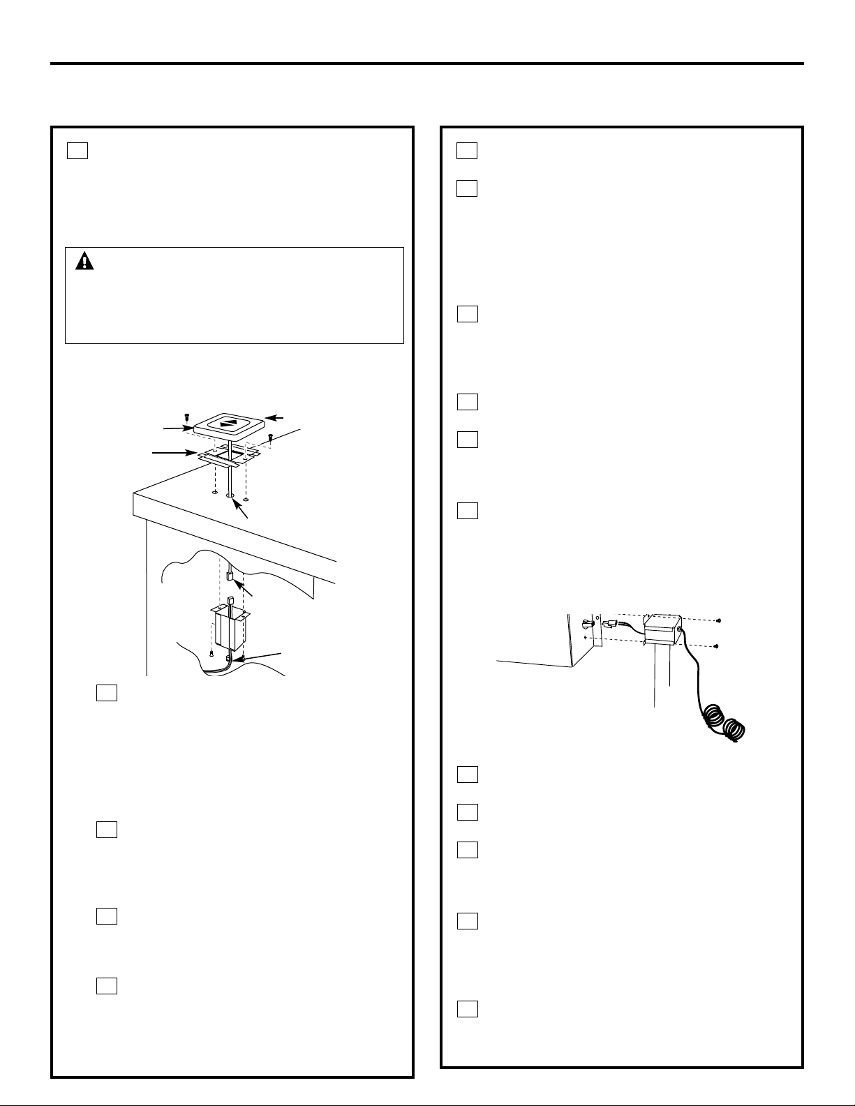
INSTALE EL INTERRUPTOR RAISE /
LOWER (SUBIR / BAJAR)
NOTA: El paso 3 es para modelos de 36″
únicamente. Ignore este paso si está
instalando un modelo de 30″.
NOTA: Determine la ubicación del
interruptor Raise / Lower. El cable tiene
una longitud de 68″.
Perfore un orificio de 3/8″ en la
ubicación deseada. Use el soporte de
montaje como una guía para ubicar
el orificio con exactitud. Revise la
interferencia entre la tapa del
interruptor, los objetos adyacentes
y los traslapos de la estufa / unidad
del ventilador.
Si el interruptor se instala en una
superficie de tableta, perfore un
orificio entre las tabletas. Use un
enmasillado aprobado para cubrir
cualquier orificio.
Centre el soporte de montaje encima
del orificio y marque los orificios
pilotos. Retire y perfore los orificios
de acuerdo al tipo de encimera.
Instale el soporte del interruptor
metálico con los tornillos (no
provistos). Seleccione los tornillos
según el tipo de encimera o use un
adhesivo aprobado localmente.
D
C
B
A
3
16
Instrucciones de instalación
INSTALACIÓN DEL SISTEMA DE VENTILACIÓN DE TIRO DESCENDENTE
ADVERTENCIA — Desconecte
la corriente eléctrica de la unidad antes de
empezar la instalación del interruptor. No
hacerlo podría resultar en lesiones personales
o daños a los controles eléctricos.
Retire la película protectora de la parte
superior de la moldura del interruptor.
Pele la película de la tira adhesiva en la parte
posterior de la montura del interruptor. Pase
el cable a través del soporte de montaje y la
encimera. Presione la montura sobre el
soporte de montaje para fijar el adhesivo.
Conecte el cable del interruptor Raise / Lower a la
caja de cables
Pase el extremo del cable con el conector a
través del orificio en el extremo de una caja
de cables. Hale aproximadamente 3″ de
longitud adicional de cable más allá del
extremo abierto de la caja.
Conecte los conectores de cable
correspondientes.
Instale la caja de cables al fondo de
la encimera o directamente detrás del
interruptor. Use tornillos o adhesivo
apropiado según el tipo de encimera.
Coloque una porción de cinta plástica de
ajuste de presión por encima del cable,
exactamente por fuera del orificio en el
extremo de la caja de cables. No pellizque o
voltee el cable. Cierre el ajuste de presión y
presione en el orificio.
Conecte el cable en la caja de control
Pase el cable de 68″ por el extremo de la otra
caja de cables.
Empuje los cables en el conector blanco
suministrado.
Empuje el conector de cables en el conector
correspondiente en la caja de control. Instale
la caja de cables en el extremo de la caja de
control con los tornillos suministrados.
Coloque cinta plástica de ajuste de presión
sobre el cable, exactamente por fuera del
orificio en el extremo en la caja de cables.
No pellizque o tuerza el cable. Cierre el ajuste
de presión y presione en el orificio.
Enrolle el cable excesivo y colóquelo a
distancia de las partes en movimiento y los
contenidos del gabinete.
E
D
C
B
A
D
C
B
A
F
E
Moldura
Soporte de
montaje
Orificio de 3/8″
Interruptor
Raise / Lower
Conector
de 2 patas
Cinta plástica de
ajuste de presión
(strain relief)
Hale una
longitud
de 3″ de
la caja
Caja de control
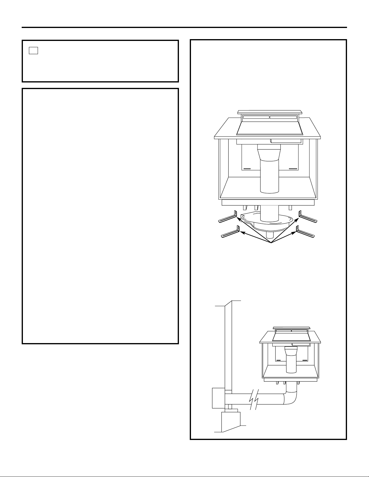
KITS OPCIONALES
El JXRB67 es un accesorio opcional
para ubicación remota al interior de la
ensambladura del ventilador / motor.
Use este kit cuando la ensambladura del
ventilador y motor se coloque debajo del
piso del gabinete.
El JXBC67 es un accesorio opcional de
cubierta para exteriores para la instalación
remota de la ensambladura del ventilador y
motor en una pared exterior.
17
Instrucciones de instalación
CONECTE LA CORRIENTE
Conecte el cable en un tomacorriente
correctamente conectado a tierra.
4
INSTALE LA ESTUFA
• Con el tiro descendente en la posición
hacia abajo, coloque la estufa en el corte.
• Empuje la estufa hacia atrás hasta el borde
posterior de la estufa apenas tocando el
borde delantero de la tapa del sistema de
tiro descendente.
• Con una moneda para medir el espesor,
alinee la estufa de manera que haya un
espacio mínimo uniforme de 0.05″ (el
espesor de una moneda de 10 centavos)
entre la estufa y la tapa del sistema de tiro
descendente.
NOTA: No fuerce la tapa del sistema de tiro
descendente para moverse hacia atrás al
alinear la estufa. Esto puede causar que la
tapa se impacte y dañe la estufa cuando la
unidad suba y baje.
NOTAS:
• La alineación exacta de la estufa y del
sistema de tiro descendente es necesaria
para asegurar que no hay interferencia
cuando la unidad suba o baje. Debe haber
un espacio de 0.05″ (el espesor de una
moneda de 10 centavos) entre el borde
trasero de la estufa y el borde delantero de
la tapa del sistema de tiro descendente.
• La estufa de radiante no se puede instalar
de manera alineada cuando se usa este
ventilador de tiro descendente.
Soportes
de montaje
Operación Seguridad
Instrucciones de
instalación
Solucionar problemasSoporte al consumidor
18
Consejos para la solución de problemas
¡Ahorre tiempo y dinero! Revise la siguiente tabla
primero y quizás no sea necesario llamar a solicitar
un servicio.
Problema Posibles causas Qué hacer
El ventilador no funciona La unidad no está • Presione el interruptor Raise / Lower.
completamente extendida.
El interruptor de control • Deslícelo a la derecha.
del ventilador puede estar la
posición de apagado (OFF).
La unidad no se levanta La unidad no está conectada • Conecte la unidad a una tomacorriente de 120V.
a la corriente.
El interruptor Raise / Lower no • Presione el interruptor por un par de segundos para
activó el motor que levanta la activar el motor.
unidad.
Es posible que el interruptor de • Revise el interruptor de circuitos. Vuelva a iniciarlo,
circuitos se haya saltado. de ser necesario.
El interruptor remoto no está • Revise todas las conexiones entre el interruptor
conectado. remoto y el cuerpo de la unidad.
Antes de llamar a solicitar servicio…
19
Soporte al consumidorOperaciónSeguridad
Instrucciones de
instalación
Solucionar problemas
■ Viajes de servicio a su residencia para enseñarle cómo
usar el producto.
■ Instalación, entrega o mantenimiento incorrectos.
■ Falla del producto por abuso, mal uso o por uso
diferente para el cual fue diseñado o por uso comercial.
■ Reposición de los filtros reemplazables.
■ Reposición de los fusibles de la casa o reinicio de los
interruptores de circuito.
■ Daños al producto causados por accidentes, incendios,
inundaciones o actos de la naturaleza.
■ Daños incidentales o consecuenciales causados por
posibles defectos con este aparato.
■ Daños causados después de la entrega.
Qué no cubre GE:
Esta garantía se extiende al comprador original y a cualquier propietario posterior por productos adquiridos
para uso en el hogar dentro de EE.UU. En Alaska la garantía excluye el costo de envío o visitas de servicio a su
residencia.
Algunos estados no permiten la exclusión o limitación de daños incidentales o consecuenciales. Esta garantía
le concede derechos legales específicos y es posible que tenga otros derechos que varían de estado a estado.
Para conocer sus derechos legales, consulte con su oficina local o estatal de asuntos del consumidor o con el
procurador general de su estado.
Si tiene un problema con la instalación, póngase en contacto con su concesionario o instalador. Usted es
responsable de ofrecer las instalaciones adecuadas eléctricas, de gas, escape y cualquier otra conexión como se
describe en las instrucciones de instalación entregadas con este producto.
Garante: General Electric Company, Louisville, KY 40225
Por el periodo de: GE reemplazará:
Un año Cualquier parte del sistema de tiro descendente que falle debido a un defecto en los materiales
A partir de la fecha o mano de obra. Durante este periodo de un año de garantía, GE también suministra, sin costo,
de compra original todo el servicio de mano de obra y de fábrica para reemplazar la parte defectuosa.
Garantía del sistema de tiro descendente de GE.
Todos los servicios de garantía son suministrados por nuestros
Centros de servicio de fábrica, o un técnico autorizado de
Customer Care
®
. Para programar un servicio, por Internet, las 24
horas al día, visítenos en www.GEAppliances.com, o llame a
800.GE.CARES (800.432.2737).
Pegue aquí su recibo. Para
obtener servicio bajo la garantía
es necesaria una prueba de la
fecha de compra original.
Impreso en Estados Unidos
Soporte al Consumidor.
Página Web de GE Appliances
www.GEAppliances.com
¿Tiene alguna pregunta sobre su electrodoméstico? ¡Pruebe la página Web de GE Appliances 24 horas al
día, cualquier día del año! Para mayor conveniencia y servicio más rápido, ya puede descargar los Manuales
de los Propietarios, pedir piezas o incluso hacer una cita en línea para que vengan a realizar una
reparación. También puede “Ask Our Team of Experts
™
” (Preguntar a nuestro equipo de expertos)
sobre cualquier cuestión y mucho más...
Solicite una reparación www.GEAppliances.com
El servicio de expertos GE está a tan sólo un paso de su puerta. ¡Entre en línea y solicite su reparación
cuando le venga bien 24 horas al día cualquier día del año! O llame al 800.GE.CARES (800.432.2737)
durante horas normales de oficina.
Real Life Design Studio (Estudio de diseño para la vida real)
www.GEAppliances.com
GE apoya el concepto de Diseño Universal—productos, servicios y ambientes que pueden usar gente de
todas las edades, tamaños y capacidades. Reconocemos la necesidad de diseñar para una gran gama de
habilidades y dificultades físicas y mentales. Para más detalles cobre las aplicaciones de GE Diseño Universal,
incluyendo ideas de diseño para la cocina para personas con discapacidades, mire nuestra página Web hoy
mismo. Para personas con dificultades auditivas, favor de llamar al 800.TDD.GEAC (800.833.4322).
Garantías ampliadas www.GEAppliances.com
Compre una garantía ampliada y obtenga detalles sobre descuentos especiales disponibles mientras su
garantía está aún activa. Puede comprarla en línea en cualquier momento, o llamar al 800.626.2224
durante horas normales de oficina. GE Consumer Home Services estará aún ahí cuando su garantía termine.
Piezas y accesorios www.GEAppliances.com
Aquellos individuos con la calificación necesaria para reparar sus propios electrodomésticos pueden
pedir que se les manden las piezas o accesorios directamente a sus hogares (aceptamos las tarjetas
VISA, MasterCard y Discover). Haga su pedido en línea hoy, 24 horas cada día o llamar por teléfono
al 800.626.2002 durante horas normales de oficina.
Las instrucciones descritas en este manual cubren los procedimientos a seguir por cualquier usuario. Cualquier
otra reparación debería, por regla general, referirse a personal calificado autorizado. Debe ejercerse precaución
ya que las reparaciones incorrectas pueden causar condiciones de funcionamiento inseguras.
Póngase en contacto con nosotros www.GEAppliances.com
Si no está satisfecho con el servicio que recibe de GE, póngase en contacto con nosotros en nuestra página
Web indicando todos los detalles así como su número de teléfono o escríbanos a:
General Manager, Customer Relations
GE Appliances, Appliance Park
Louisville, KY 40225
Registre su electrodoméstico www.GEAppliances.com
¡Registre su nuevo electrodoméstico en línea—cuando usted prefiera! El registrar su producto a tiempo le
proporcionará, si surgiera la necesidad, una mejor comunicación y un servicio más rápido bajo los términos
de su garantía. También puede enviar su tarjeta de registro pre-impresa que se incluye en el material
de embalaje.
20

