Loading ...
Loading ...
Loading ...
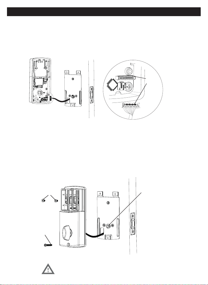
Figure 12a
A
5/16” (8mm) screws
1”(25mm) screw
D
Figure 11a
Match Color
NOTE: Tailpiece must be
positioned vertically
11. ATTACH THE CONTROL WIRE TO THE INTERIOR ASSEMBLY
a. Use care to attach the Control Wire male plug to the Interior Assembly female
socket connector.
b. Carefully insert the male plug, smooth side up, into the female socket on the
12. ATTACH THE INTERIOR ASSEMBLY TO DOOR
a. IMPORTANT:
left hand door.
b. Make sure the tailpiece (Figure 12a) is in the vertical position.
c. Position the Interior Assembly over the vertically positioned tailpiece and carefully push
the Interior Assembly against the door (Figure 12a).
d. Using two 5/16” (8mm) screws and one 1” (25mm) screw, attach the Interior Assembly to the Mounting
Plate. DO NOT OVER TIGHTEN SCREWS
NOTE: Lock and unlock using Interior Knob to see if
the latch is opening and closing easily.
INSTALLING INTERIOR ASSEMBLY
Loading ...
Loading ...
Loading ...