Please read these operating instructions thoroughly
before using your air conditioner and keep for future reference.
Il est recommandé de lire attentivement ce manuel avant
d'utiliser l'appareil. Conservez ce manuel.
For U.S customers :
For assistance, please call : 1-800-211-PANA(7262) or
Register your product at : http://www.panasonic.com/register
For customers in Canada :
For assistance, please call : 905-624-5505
Au Canada : Pour de l'aide, composez le 905-624-5505.
INSTALLATION AND OPERATING INSTRUCTIONS
MANUEL D'INSTALLATION ET D'UTILISATION
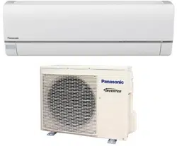
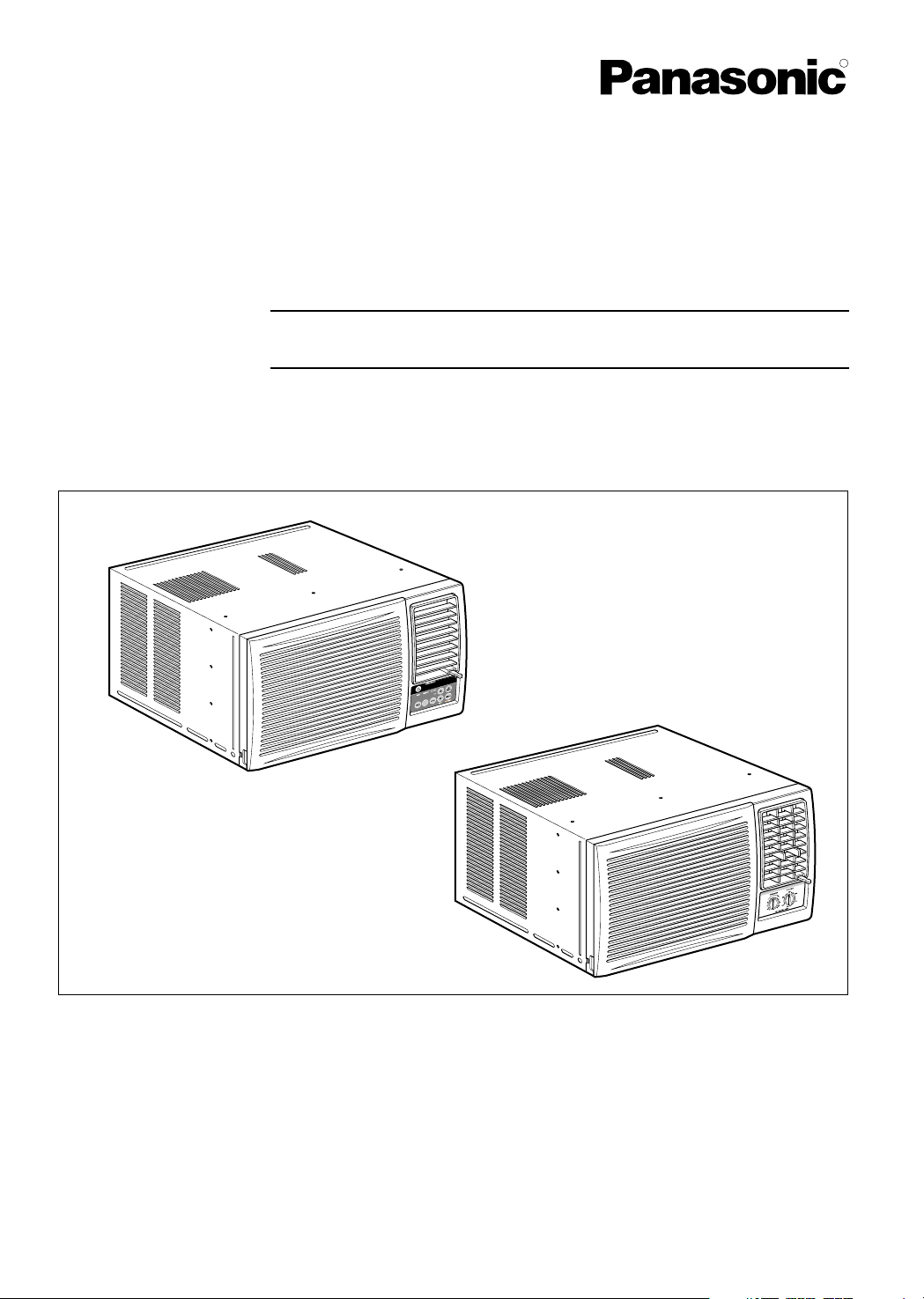
Room Air Conditioner
Climatiseur de fenêtre
Models, Modèles:
CW-XC64HU, CW-XC64HK, CW-C84GU
CW-XC84GU, CW-XC84HU, CW-XC84HK
CW382820391B
R

2
Safety Precautions
About the Controls on the Air Conditioner
Features and Installation
Before you call for service...
FOR YOUR RECORDS
Staple your receipt to this page in case you need it later.
Write down the model and serial numbers here:
Model #
Serial #
You can find them on a label on the side of each unit.
Dealer's Name
Date Purchased
Inside you will find many helpful hints on how to use and
maintain your air conditioner properly. Just a little preventive
care on your part can save you a great deal of time and
money over the life of your air conditioner.
You'll find many answers to common problems in the chart
of troubleshooting tips. If you review our chart of
Troubleshooting Tips first, you may not need to call for
service at all.
READ THIS MANUAL
CAUTION
• Contact the authorized Service technician for repair or
maintenance of this unit.
• The air conditioner is not intended for use by young
children or infirm persons without supervision.
• Young children should be supervised to ensure that they
do not play with the air conditioner.
Safety Precautions
Safety Precautions .............3
About the Controls on
the Air Conditioner
Controls..............................5
Remote Controller ..............7
Ventilation ..........................8
Air Direction........................8
How to Secure Drain Pipe
....8
Care and Maintenance
Air Filter Cleaning...............9
Features
Features ...........................10
Installation
How to Install the Unit ......11
Window Requirements .....11
Installation Kit Contents ...12
Suggested Tool
Requirements...................12
Cabinet Installation...........13
Electrical Data ..................15
Electrical Safety ...............16
Before you call for
service...
Normal Operation.............17
Abnormal Operation .........17

WARNING
3
Safety Precautions
Safety Precautions
To prevent injury to the user or other people and property damage, the following instructions must be
followed.
■ Incorrect operation due to ignoring of instruction will cause harm or damage. The seriousness is classified
by the following indications.
WARNING : This symbol indicates the possibility of death or serious injury.
CAUTION
:
This symbol indicates the possibility of injury or damage to
property only.
■ Meanings of symbols used in this manual are as shown below.
Be sure not to do this.
Be sure to follow the instructions.
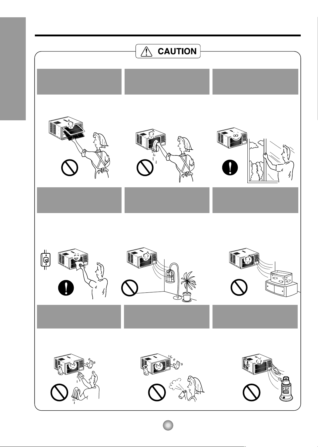
Plug in the power plug
properly.
• Otherwise, it will cause electric
shock or fire due to heat
generation.
Do not operate or stop the
unit by inserting or pulling
out the power plug.
• It will cause electric shock or fire
due to heat generation.
Do not damage or use an
unspecified power cord.
• It will cause electric shock or fire.
•
If the power cord is damaged, it must
be replaced by the manufacturer or
an authorized service center or a
similarly qualified person in order to
avoid a hazard.
Do not modify power cord
length or share the outlet
with other appliances.
• It will cause electric shock or fire
due to heat generation.
Do not operate with wet
hands or in a damp
environment.
• It will cause electric shock.
Do not direct air flow at room
occupants.
• This could lead to health
problems.
4
Safety Precautions
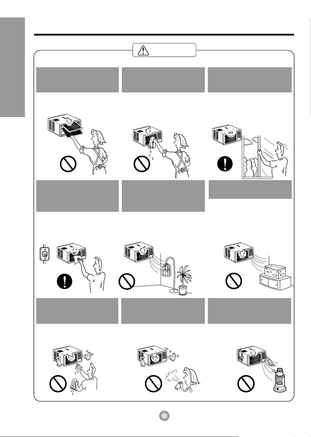
When the air filter is to be
removed, do not touch the
metal parts of the unit.
• It may cause an injury.
Do not clean the air
conditioner with water.
• Water may enter the unit and
degrade the insulation. It may
cause an electric shock.
Ventilate well when used
together with a stove, etc.
• An oxygen shortage may occur.
When the unit is to be
cleaned, switch off, and turn
off the breaker.
• Since the fan rotates at high
speed during operation, it may
cause an injury.
Do not put a pet or house
plant where it will be exposed
to direct air flow.
• This could injure the pets or
plants.
Do not use for special
purposes.
• Do not use this air conditioner to
preserve precision devices, food,
pets, plants, and art objects.
It may cause deterioration of
quality, etc.
Do not operate switches
with wet hands
.
• It may cause an electric shock.
Do not apply an insecticide
or flammable spray.
• It may cause a fire or deformation
of the cabinet.
Do not put a heater, etc.
where it is exposed to direct
air flow.
•
It may cause imperfect
combustion.
5
About the Controls on the Air Conditioner
About the Controls on the Air Conditioner
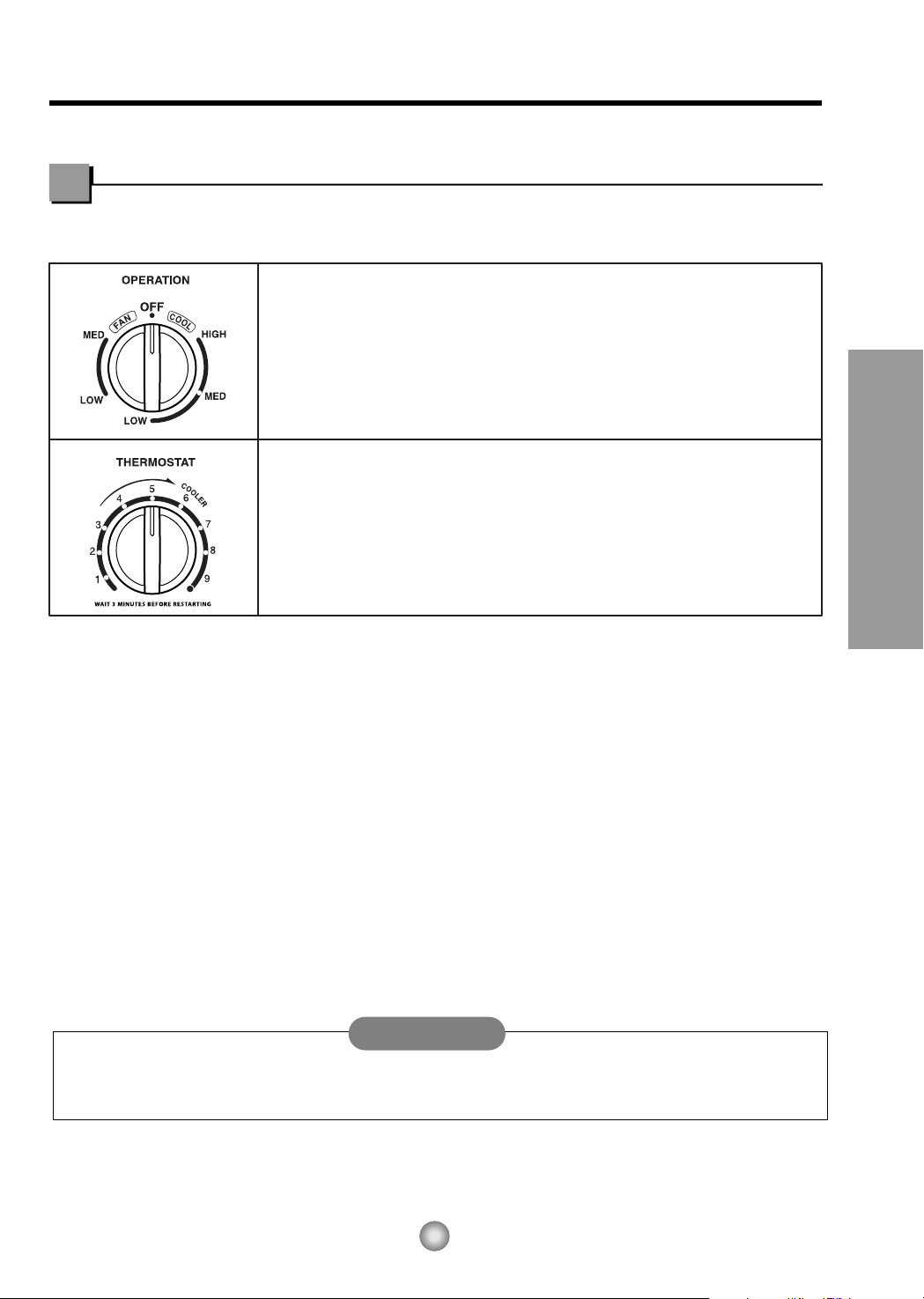
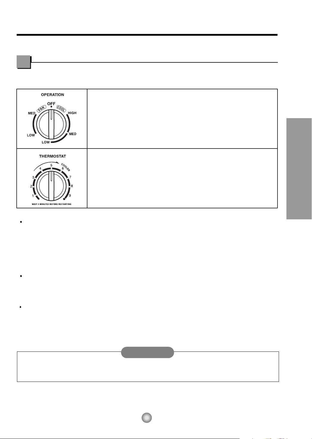
The controls will look like one of the following.
Controls
When the air conditioner has performed its cooling operation and is turned off or set to the fan
position, wait at least 3 minutes before resetting to the cooling operation again.
Off - Turns air conditioner off.
Med Fan - Med speed fan operation without cooling.
Low Fan - Low speed fan operation without cooling.
High Cool - Cooling with high speed fan operation.
Med Cool - Cooling with med speed fan operation.
Low Cool - Cooling with low speed fan operation.
This automatically controls the temperature of the indoor air.
Turn the knob so that arrow points to the higher number for greater cooling.
Point the arrow to the lower number for more moderate cooling.
(i.e. the higher the number, the greater the cooling)
• FOR NORMAL COOLING
1. Turn the operation switch to the High Cool or the Low Cool setting.
2. Set the Thermostat control to the desired temperature mark 5 (the mid-point is a good starting position).
If the room temperature is not satisfactory after a reasonable time, adjust the control to a cooler or warmer
setting, as appropriate.
• FOR MAXIMUM COOLING
1. Turn the Operation Knob to the High Cool setting.
2. Set the Thermostat control to the largest (9) temperature mark.
• FOR QUIETER OPERATION
1. Turn the Operation Knob to the Low Cool setting.
2. Set the Thermostat control as needed.
CAUTION
Model : CW-C84GU
Model: CW-XC84HU
Models: CW-XC64HK, CW-XC84HK
Model: CW-XC80HU
TIMER FANECONOMY
COOL
DRY
TIMERTIMER
MODEMODE
OFF/ON
FAN
SPEED
AIR
SWING
AIR
SWING
F
hr
FAN
COOL
DRY
hr
F
OPERATION
TEMPTEMP
TIMER MODE
OFF/ON
FAN
SPEED
FAN
SPEED
4
1
7
8
3 2 5
4
1
3 6 2 5
8
1
8
4
3 2 5
OPERATION
TEMP
Models: CW-XC64HU, CW-XC84GU
TIMER
AIR
SWING
AIR
SWING
FANECONOMY
COOL
DRY
TIMERTIMER
MODEMODE
OFF/ON
F
hr
FAN
SPEED
4
1
8
3 2 5
OPERATION
TEMP
6
About the Controls on the Air Conditioner
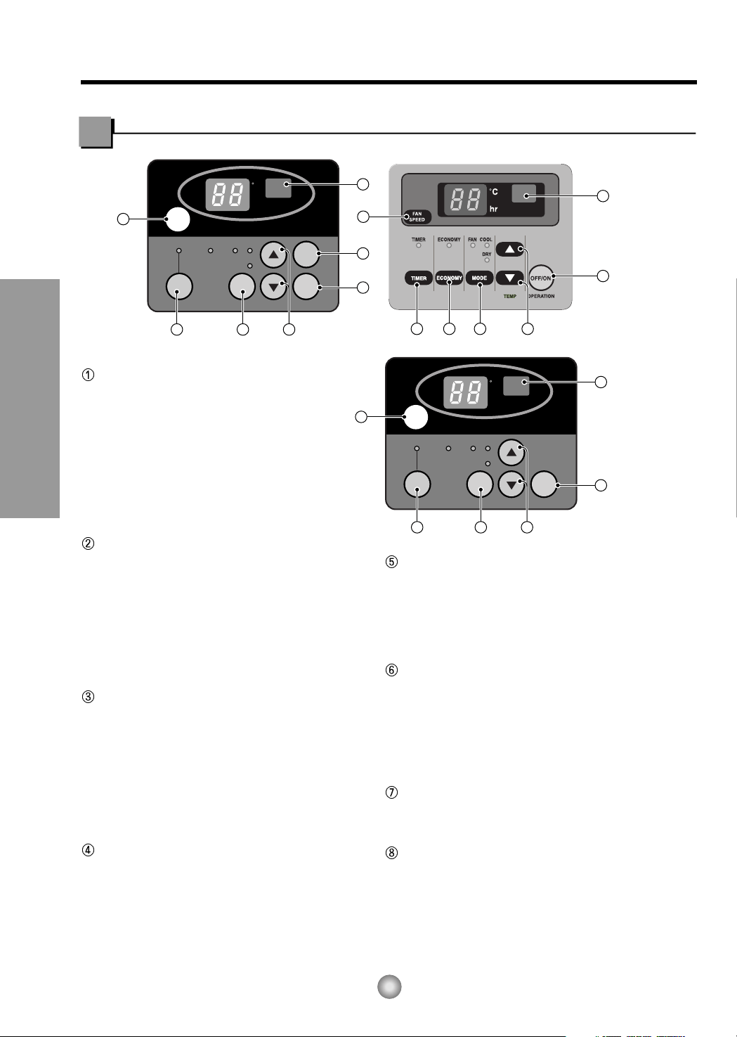
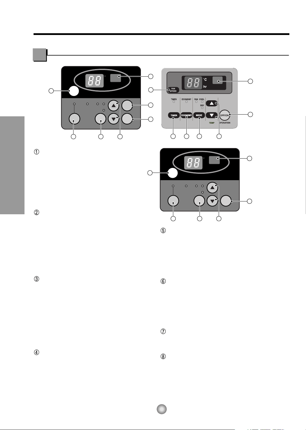
Controls
OPERATION
• To turn the air conditioner ON, push the
OFF/ON button.
To turn the air conditioner OFF, push the
button again.
• This button takes priority over any other
buttons.
• When you first turn it on, the air conditioner
is on the High cool mode and the temp. at
72°F (22°C)
MODE
• Evey time you push this button,it will toggle
between COOL, FAN, DRY.
(Models:CW-XC64HK,CW-XC84HK)
• Every time you push this button, it will
toggle between COOL,ECONOMY, FAN
and DRY.
(Models:CW-XC64HU, CW-XC84HU,
CW-XC84GU)
ON/OFF TIMER
• Every time you push the TIMER button,
timer is set as follows. (1Hour → 2Hours →
3Hours → 4Hours → 5Hours → 6Hours →
7Hours → 8Hours → 9Hours → 10Hours →
11Hours → 12Hours → O)
• The Setting Temperature will be raised by
2°F(1˚C) 30 min. later and by 2°F(1˚C) after
another 30 min.
FAN SPEED
• Every time you push this button it is set as
follows. {High(F3) → Low(F1) → Med(F2) →
High(F3)...}.
TEMPERATURE SETTING
• This button can automatically control the
temperature of the room. The temperature can
be set within a range of 60°F to 86°F by 1°F
(16˚C to 30˚C by 1˚C) Select the lower number
for lower temperature of the room.
ECONOMY
(Models: CW-XC64HK, CW-XC84HK)
• If you push the button, the fan stops when the
compressor stops cooling.
• Approximately every 3 minutes the fan will turn
on and check the room air to determine if
cooling is needed.
AIR SWING
• This button can automatically control the air flow
direction.
REMOTE CONTROL SIGNAL RECEIVER
OPERATION
TEMP
TIMER
AIR
SWING
MODE
ECONOMY
FAN SPEED
1
3
2 4
6
5
7
OPERATION
TEMP
TIMER
MODE
ECONOMY
FAN SPEED
1
3
2 4
6
5
Model: CW-XC84HU
Models: CW-XC64HU, CW-XC64HK
CW-XC84GU, CW-XC84HK
7
About the Controls on the Air Conditioner
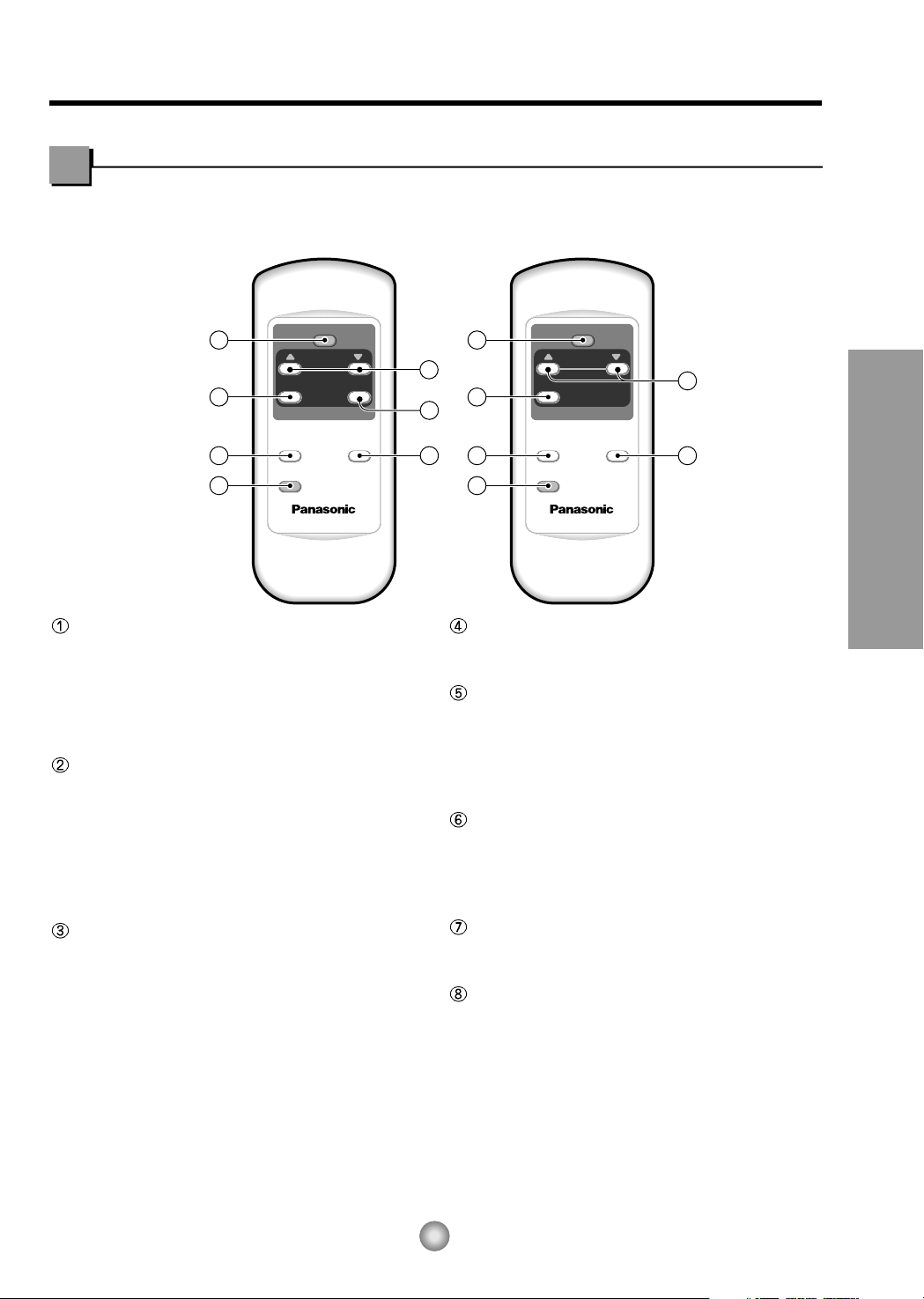
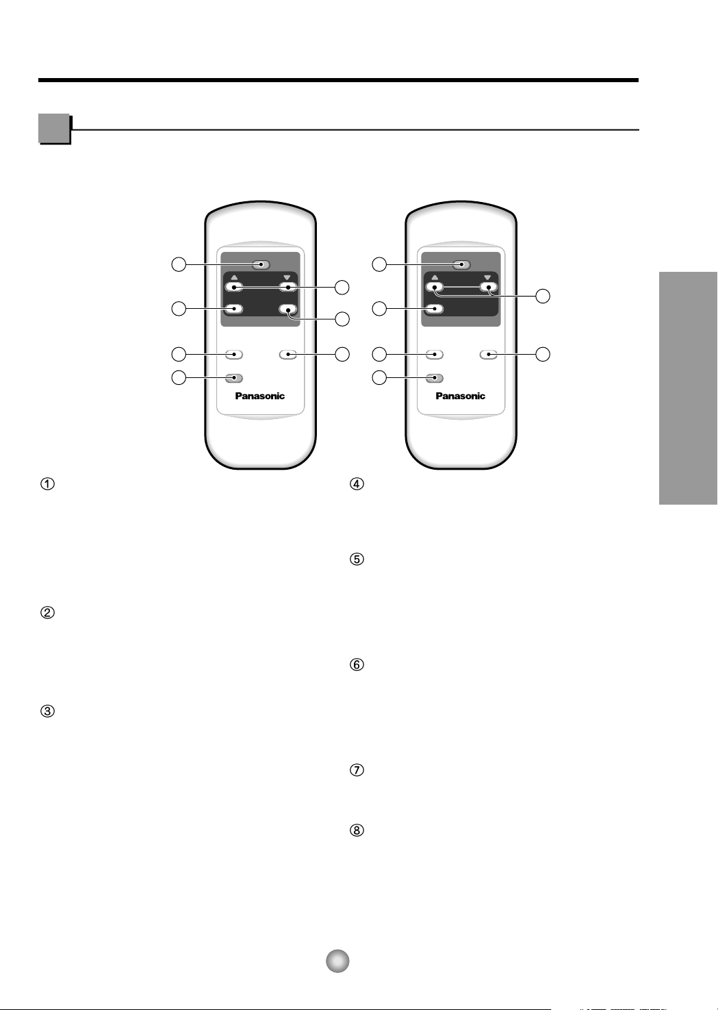
Remote controller
OPERATION
• To turn the air conditioner ON, push the button.
To turn the air conditioner OFF, push the button
again.
• This button takes priority over any other buttons.
• When you first turn it on, the air conditioner is on
the High cool mode and the temp. at 72°F (22˚C).
MODE
• Every time you push this button, it will toggle
between COOL, FAN and DRY.
(Models:CW-XC64HK, CW-XC84HK)
• Every time you push this button,it will toggle
between COOL, ECONOMY, FAN and DRY.
(Models: CW-XC64HU, CW-XC84HU,
CW-XC84GU)
ON/OFF TIMER
- STOPPING OPERATION
• Every time you push this button, when the air
conditioner is operating, timer is set as follows.
(1Hour → 2Hours → 3Hours → 4Hours → 5Hours
→ 6Hours → 7Hours → 8Hours → 9Hours →
10Hours → 11Hours → 12Hours → O)
• The Setting Temperature will be raised by
2°F (1°C) 30 min. later and by 2°F (1°C) after
another 30 min.
- STARTING OPERATION
• Every time you push this button, when the air
conditioner is not operating, timer is set as follows.
(1Hour → 2Hours → 3Hours → 4Hours → 5Hours
→ 6Hours → 7Hours → 8Hours → 9Hours →
10Hours → 11Hours → 12Hours → O)
FAN SPEED
• Every time you push this button it is set as follows.
{High(F3) → Low(F1) → Med(F2) → High(F3)...}.
TEMPERATURE SETTING
• This button can automatically control the
temperature of the room.
The temperature can be set within a range of 60°F
to 86°F by 2°F.(16˚C to 30˚C by 1˚C) Select the
lower number for lower temperature of the room.
ECONOMY
• If the switch is set to "On", the fan stops when the
compressor stops cooling. Approximately every 3
minutes the fan will turn on and check the room air
to determine if cooling is needed.
AIR SWING
• This button can automatically control the air flow
direction.
DRY
• When this unit is in dry mode, the fan rotates in
low speed. The fan stops when the compressor
stops cooling.
Approximately every 3 minutes the fan will turn on
and the unit checks the room air temperature to
set itself.
Precaution:
The Remote Controller will not function properly if strong light strikes the sensor window of the
air conditioner or if there are obstacles between the Remote Controller and the air conditioner.
VENTCLOSE
OPEN
Part
A
Part
B
Drain pipe
Drain cap
Fig. 4
Fig. 3
Fig. 2
DRAIN
PA N
DRAIN HOSE
Inside diameter 17mm (5/8")
Fig. 1
CABINET
SCREW
Controlled
manually
Controlled
manually
Controlled by Remote
Controller
(Model: CW-XC84HU)
O
F
F
/
O
N
O
P
E
R
A
T
I
O
N
T
E
M
P
/
T
I
M
E
R
C
O
O
L
F
A
N
H
I
G
H
M
E
D
L
O
W
M
O
D
E
F
A
N
S
P
E
E
D
S
E
T
T
I
M
E
R
S
E
T
/
C
A
N
C
E
L
A
I
R
S
W
I
N
G
E
C
O
N
O
M
Y
h
r
F
W
i
r
e
l
e
s
s
R
e
m
o
t
e
C
o
n
t
r
o
l
Remove the
rubber plug
O
F
F
/
O
N
O
P
E
R
A
T
I
O
N
T
E
P
/
T
I
C
O
O
L
F
A
N
H
I
G
H
M
E
D
L
O
W
M
O
E
F
A
N
S
P
E
E
D
S
E
T
T
I
M
E
R
S
E
T
/
C
N
E
A
I
R
E
C
O
N
O
M
Y
F
W
i
r
e
l
e
s
s
R
e
m
o
te
C
o
n
t
r
o
l
8
About the Controls on the Air Conditioner
Additional controls and important information.
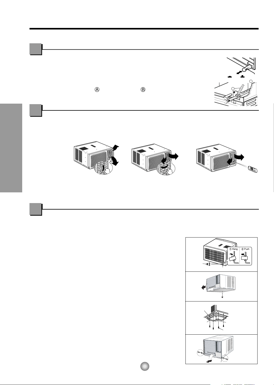
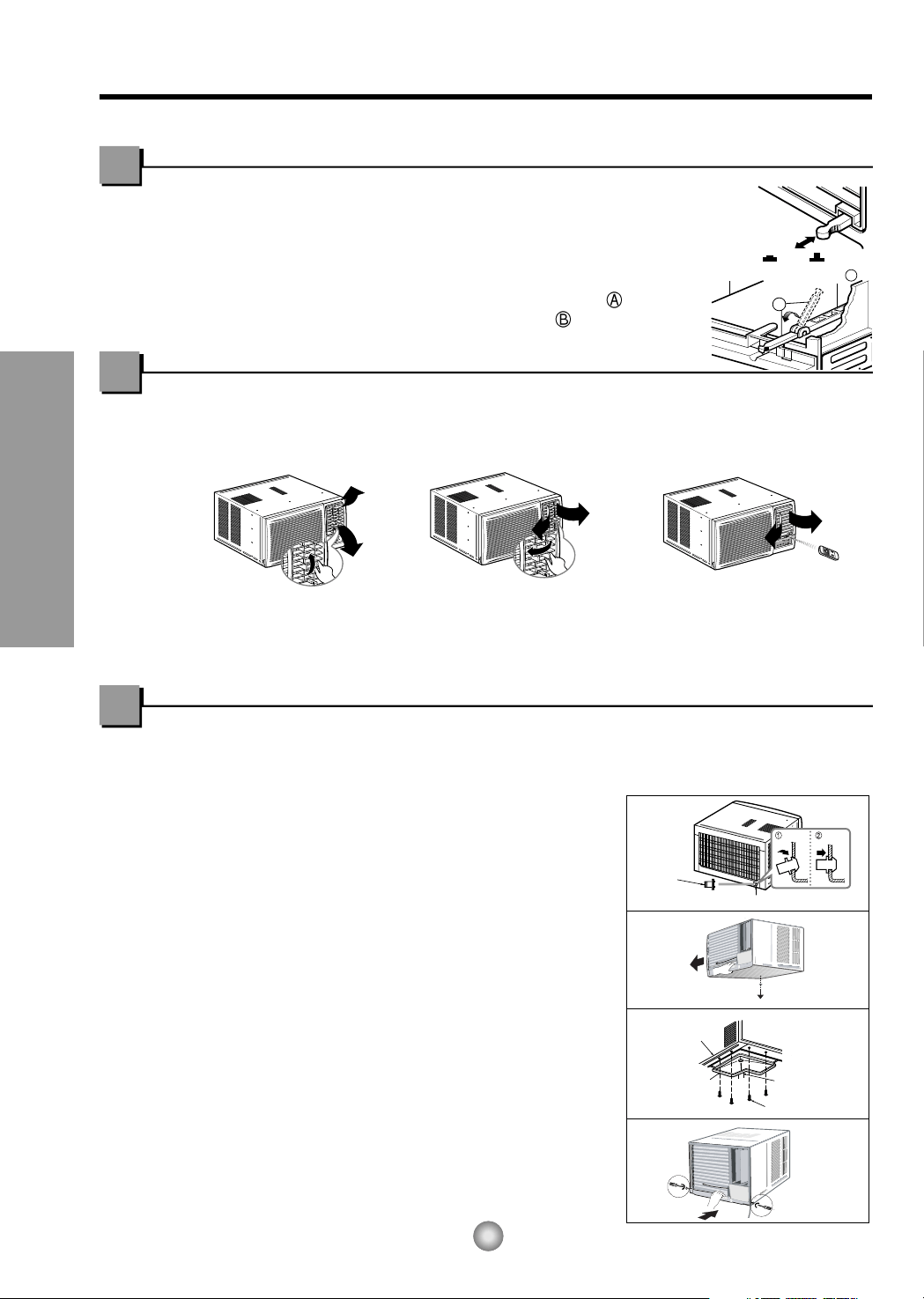
Ventilation
The ventilation lever must be in the CLOSE position in order to maintain the best
cooling conditions. When fresh air is necessary in the room, set the ventilation
lever to the OPEN position.
The damper is opened and room air is drawn out.
NOTE: Before using the ventilation feature, and prior to installing the front grille,
pull down part until level with part .
Air Direction
The vertical air direction is adjusted by
rotating the horizontal louver forward or
backward manually.
The horizontal air direction is adjusted by rotating
the vertical louver right or left manually or by
Remote Controller.
The direction of air can be controlled wherever you want to cool by adjusting the horizontal
louver and the vertical louver.
• VERTICAL AIR-DIRECTION CONTROL
•
HORIZONTAL AIR-DIRECTION CONTROL
How to Secure the Drain Pipe
In humid weather, excess water may cause the BASE PAN to overflow. To drain the water, remove the
DRAIN CAP and secure the DRAIN PIPE to the rear hole of the BASE PAN. Press the drain pipe into the
hole by pushing down and away from the fins to avoid injury.(See Fig.1)
Optional(CW3H02502C)
1. Remove the rubber plug and slide the chassis out
from the cabinet.(See Fig.2)
2. Install the drain pan over the corner of the cabinet
where you removed the plug with 4 (or 2)
screws.(See Fig.3)
3. Connect the drain hose to the outlet located at the
bottom of the drain pan. You can purchase the drain
hose or tubing locally to satisfy your particular
needs. (Drain hose is not supplied).(See Fig.3)
4. Select the most appropriate connection from among
the figures to the right (by considering the hole of the
unit) to fit drain pan to your own unit.(See Fig.3)
5. Slide the chassis back into the cabinet. Reinstall the
cabinet screws. Secure the cabinet to chassis by
using screws. (See Fig.4)
9
About the Controls on the Air Conditioner
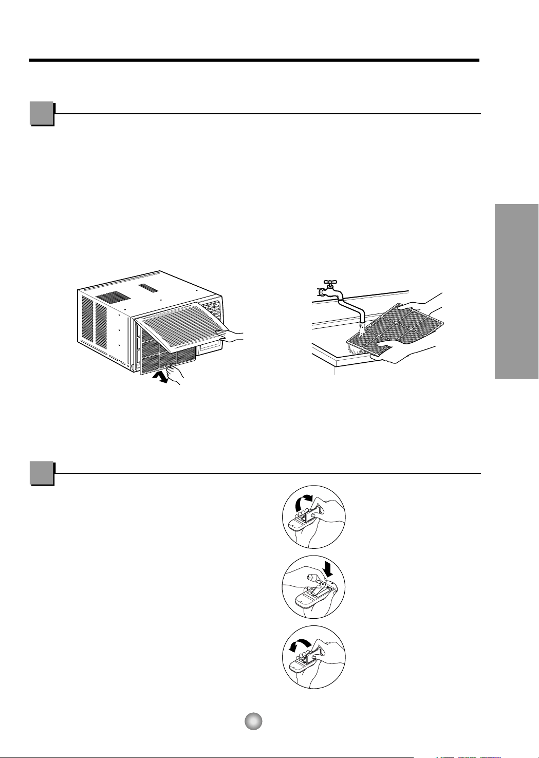
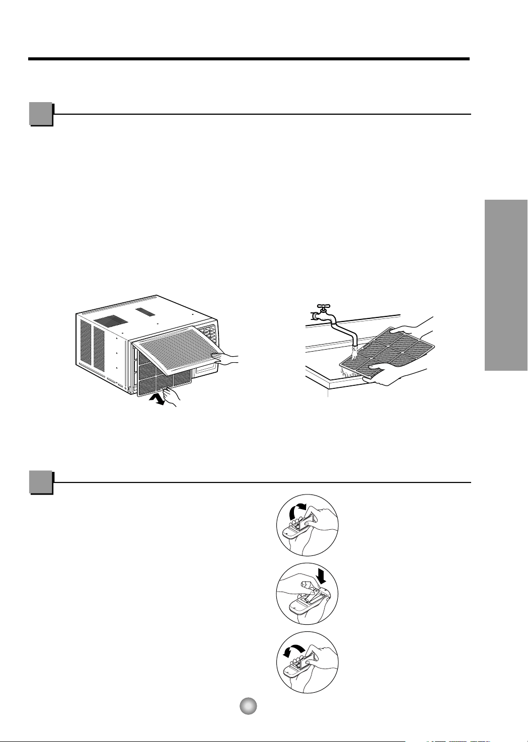
Air Filter Cleaning
The air filter behind the front grille should be checked and cleaned at least once every 2
weeks or more often if necessary.
TO REMOVE:
1. Open the inlet grille upward by pulling out the bottom of the inlet grille or downward by
pulling out the top of the inlet grille.
2. Using the tab, pull up slightly on the filter to release it and pull it down or up.
3. Clean the filter with warm, soapy water under 40°C (104°F).
4. Rinse and gently shake the water from the filter and let it dry before replacing it.
CAUTION: DO NOT operate the air conditioner without a filter because dirt and lint will
clog it and reduce performance.
How to Insert Batteries
Care and Maintenance
TURN THE AIR CONDITIONER OFF AND REMOVE THE PLUG FROM THE POWER OUTLET.
1. Remove the cover from the back of the
remote controller.
2. Insert two AAA dry cell batteries.
• Be sure that the (+) and (-) directions
are correct.
• Be sure that both batteries are new.
3. Re-attach the cover.
• Do not use rechargeable
batteries. Such batteries
differ from standard dry
cells in shape,
dimensions, and
performance.
• Remove the batteries
from the remote
controller if the air
conditioner is not going
to be used for an
extended length of time.
10
Features and Installation
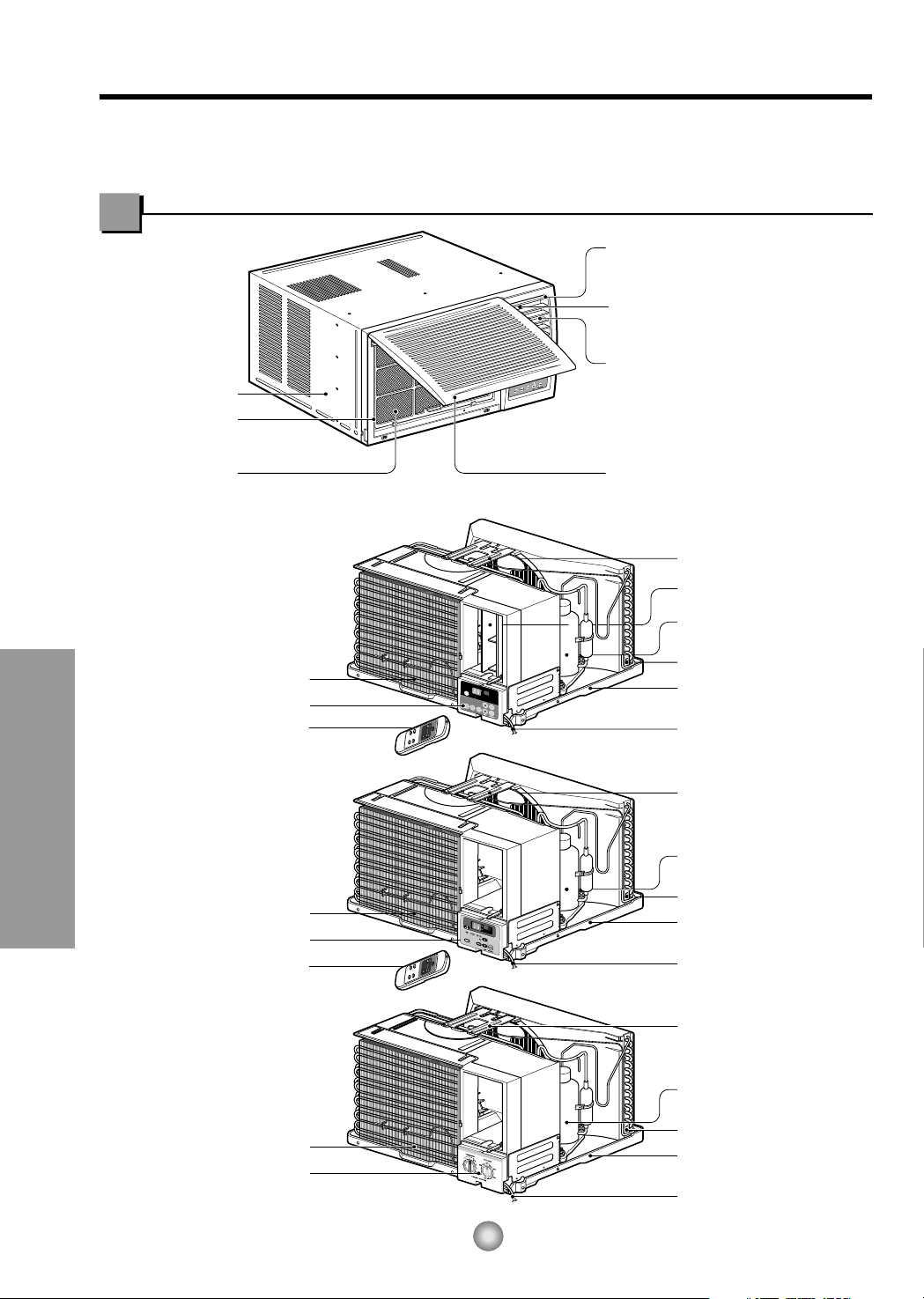
Learning parts name prior to installation will help you understand the installation procedure.
Features
Features
CABINET
FRONT GRILLE
AIR FILTER
AIR INTAKE
(INLET GRILLE)
AIR DISCHARGE
HORIZONTAL AIR DEFLECTOR
(VERTICAL LOUVER)
VERTICAL AIR DEFLECTOR
(HORIZONTAL LOUVER)
EVAPORATOR
POWER CORD
BASE PAN
CONDENSER
COMPRESSOR
BRACE
BRACE
CONTROL BOARD
EVAPORATOR
POWER CORD
BASE PAN
CONDENSER
COMPRESSOR
BRACE
CONTROL BOARD
REMOTE CONTROLLER
VERTICAL LOUVER
Models: CW-XC84HU
Models: CW-XC64HK
CW-XC84HK
CW-XC64HU
CW-XC84GU
REMOTE CONTROLLER
F
A
N
E
C
O
N
O
M
YC
O
O
L
D
R
Y
T
I
M
E
R
T
I
M
E
R
T
I
M
E
R
M
O
D
E
M
O
D
E
O
F
F
/
O
N
F
h
r
F
A
N
S
P
E
E
D
A
I
R
S
W
I
N
G
A
I
R
S
W
I
N
G
POWER CORD
BASE PAN
CONDENSER
COMPRESSOR
EVAPORATOR
CONTROL BOARD
Model: CW-C84GU
About 12.7mm (
1
/
2
")
76.2cm (30")~
152.4cm (60")
Awning
Cooled air
Fence
Over 50.8cm (20")
Heat
radiation
55.8cm (22") to
91.44cm (36")
Offset
12.7mm (
1
/
2
") to
31.8mm (1
1
/
4
")
Sill
Exterior
Interior wall
47cm (18
1
/2") min.
(Without frame curtain)
Stool
38cm (15") min
(With frame curtain)
11
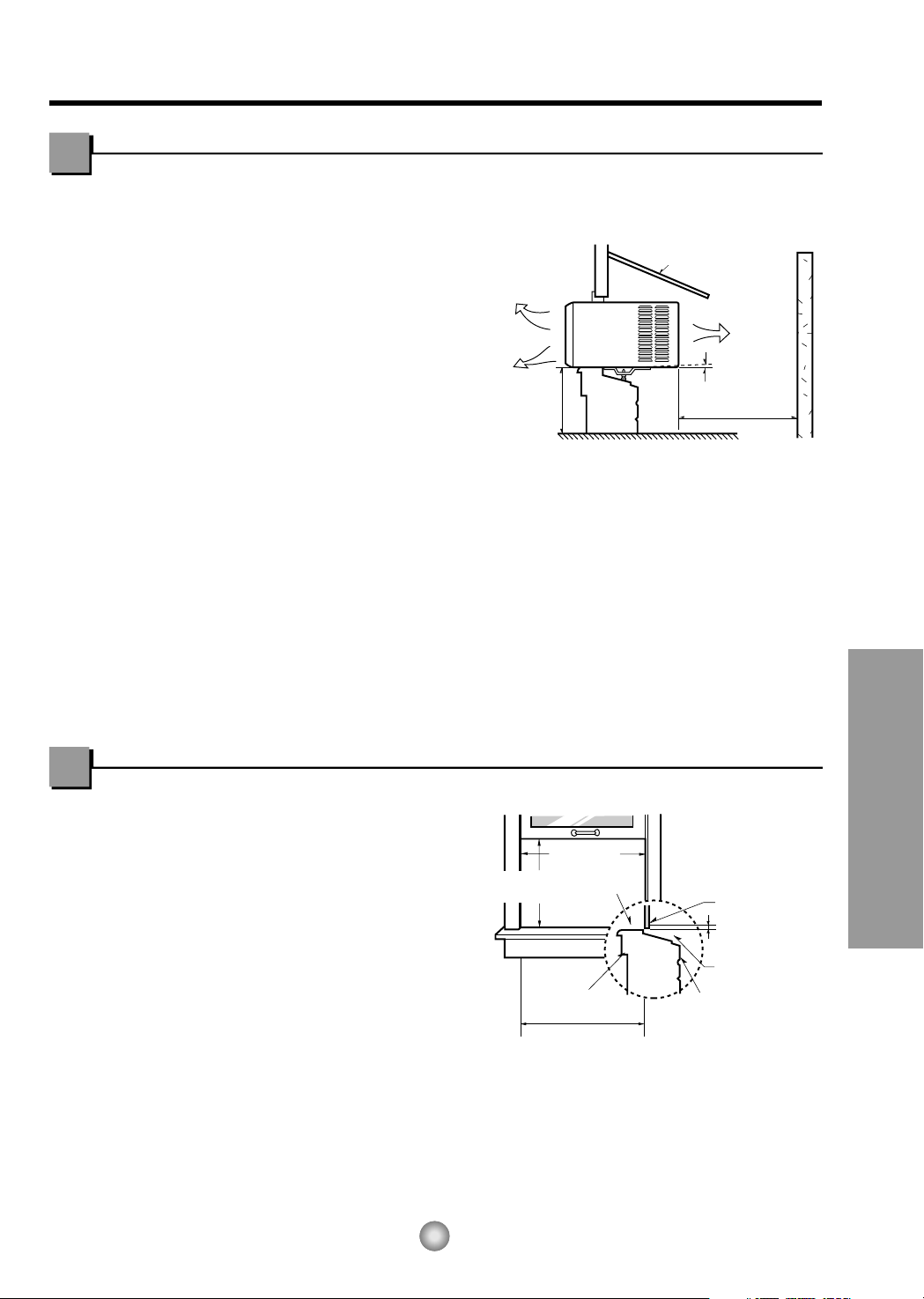
INSTALLATION
Features and Installation
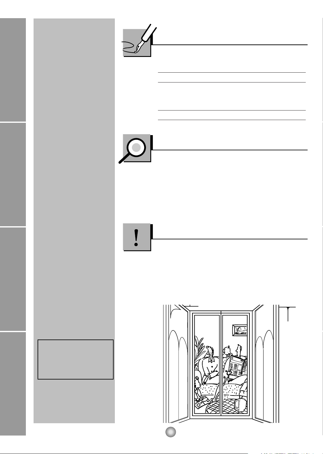
1. To prevent vibration and noise, make sure
the unit is installed securely and firmly
2. Install the unit where the sunlight does not
shine directly on the unit.
3. The outside of the cabinet must extend
outward for at least 28cm (11") and there
should be no obstacles, such as a fence or
wall, within 50.8cm (20") from the back of
the cabinet because it will prevent heat
radiation of the condenser.
Restriction of outside air will greatly reduce
the cooling efficiency of the air conditioner.
CAUTION: All side louvers of the cabinet must remain exposed to the outside of the
structure.
4. Install the unit a little slanted so the back is slightly lower than the front
(about 12.7mm (
1
/
2")).
This will force condensed water to flow to the outside.
5. Install the unit with the bottom about 76.2cm (30")~152.4cm (60") above the floor level.
Window Requirements
NOTE: All supporting parts should be secured to firm wood, masonry, or metal.
This unit is designed for installation in
standard double hung windows with actual
opening widths from 55.88cm (22") to
91.44cm (36").
The top and bottom window sash must open
sufficiently to allow a clear vertical opening of
38cm (15") from the bottom of the upper sash
to the window stool.
How to Install the Unit
9
5
5
(Type A)
5
(Type A)
Lower guide
11
1
2 3 4
8 11
12
9
765
10
Shipping
Screws
Lower guide
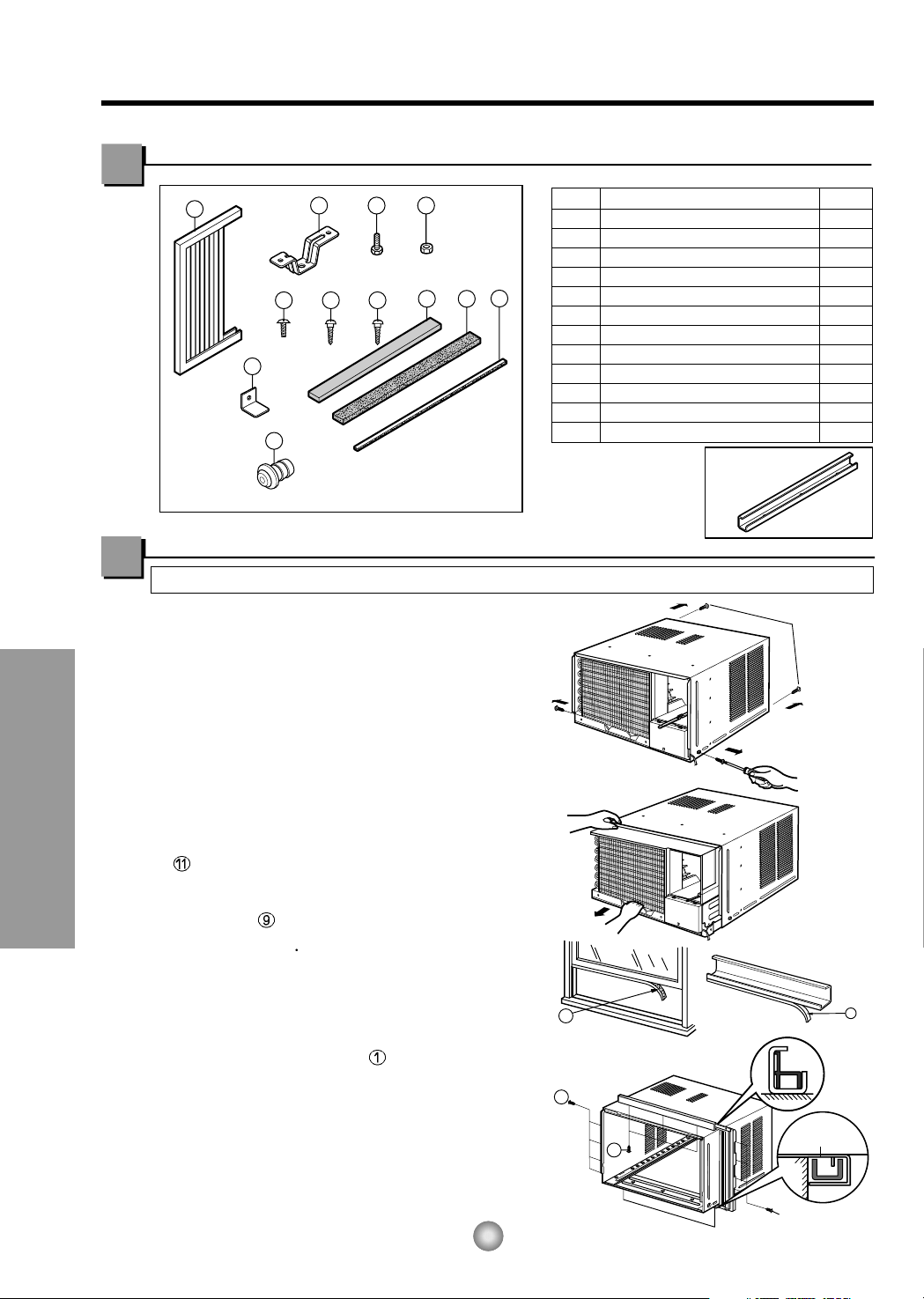
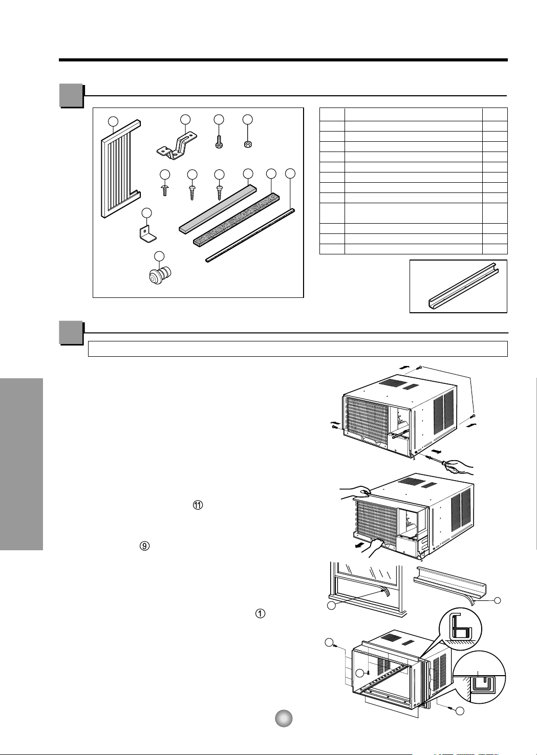
PREPARATION OF CHASSIS
1. Remove the screws which fasten the cabinet
at both sides and at the back.
2. Slide the unit from the cabinet by gripping the
base pan handle and pulling while bracing the
cabinet.
3. Cut the window sash seal to the proper
length.
Peel off the backing and attach the FOAM-PE
to the underside of the window sash.
4. Remove the backing from the top upper guide
FOAM-PE and attach it to the bottom of
the upper guide
5. Attach the upper guide onto the top of the
cabinet with 3 type A screws from underneath
the top of the cabinet.
6. Insert the Frame Curtain into the upper
guide.
7. Fasten the curtains to the unit with 4 Type
A screws.
12
Features and Installation
Suggested Tool Requirements
Installation Kit Contents
SCREWDRIVER(+, -), RULER, KNIFE, HAMMER, PENCIL, LEVEL
NO. NAME OF PARTS Q'TY
1 FRAME CURTAIN 2
2 SILL SUPPORT 2
3 BOLT 2
4 NUT 2
5
SCREW(TYPE A) (10mm (
25/64")
)
16
6
SCREW(TYPE B)
3
7
SCREW(TYPE C)
5
8
FOAM-STRIP
1
9
FOAM-PE (466mm x 10mm x 2mm)
1
10
WINDOW LOCKING BRACKET
1
11
FOAM-PE
(920mm x 30mm x 2mm)
1
12 DRAIN PIPE 1
D5.1mm(3/16")/16mm(5/8")
D4.1mm(5/32")/16mm(5/8")
■ Top retainer bar is
in the product
package.
13
Features and Installation
Upper Guide
Window Sash
Window sill
Front Angle
Upper guide
Frame Curtain
1
Foam-pe
9
Foam-pe
11
Cabinet
INDOOR OUTDOOR
INDOOR OUTDOOR
Sash track
Front Angle
Cabinet
About 12.7mm (
1
/2")
About 12.7mm (
1
/
2
")
Sill Support
2
Nut
4
Bolt
3
Frame Guide
9
Screw (Type B)
6
Screw (Type B)
6
Sill support
2
Sill support
2
Screw (Type A)
5
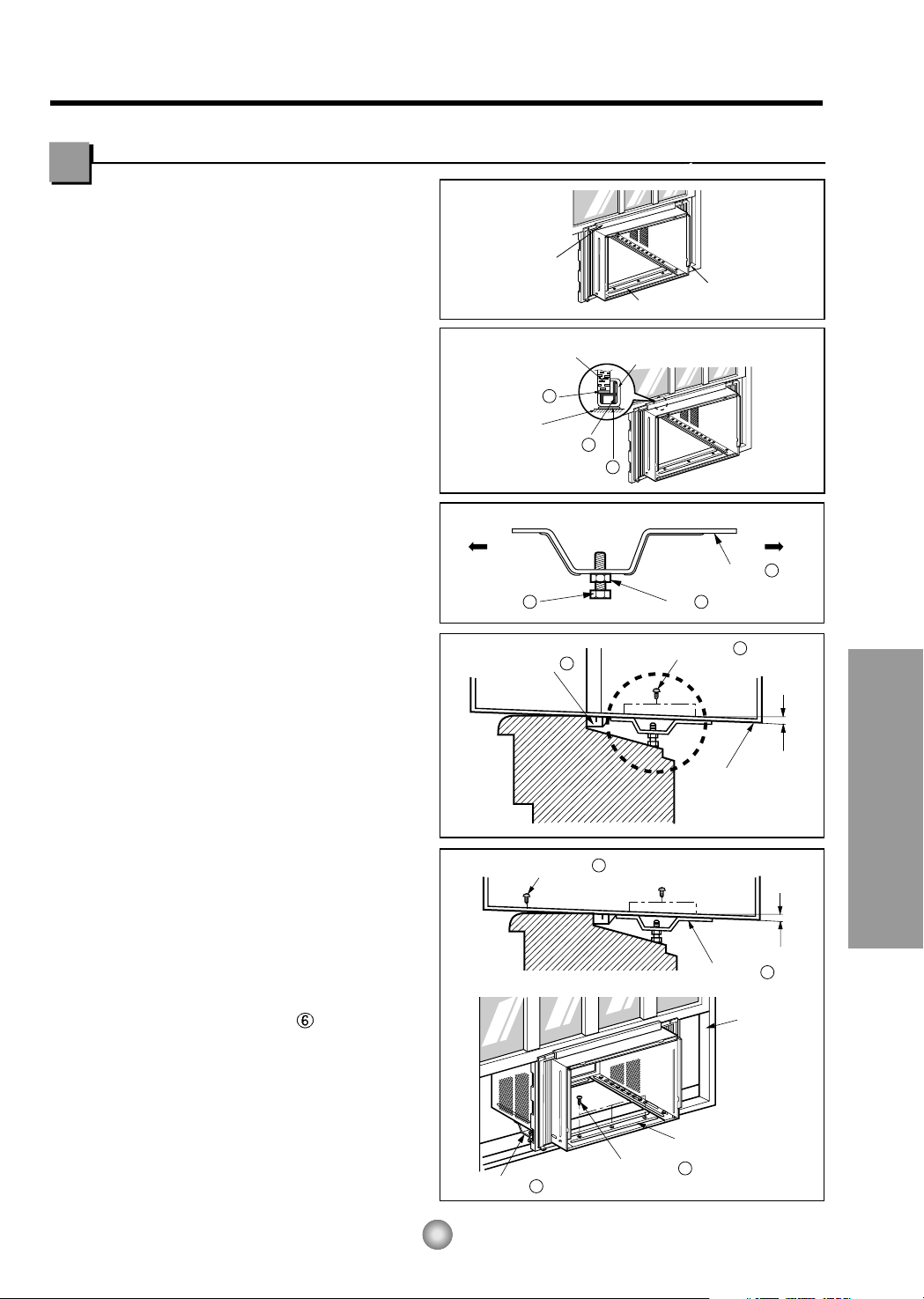
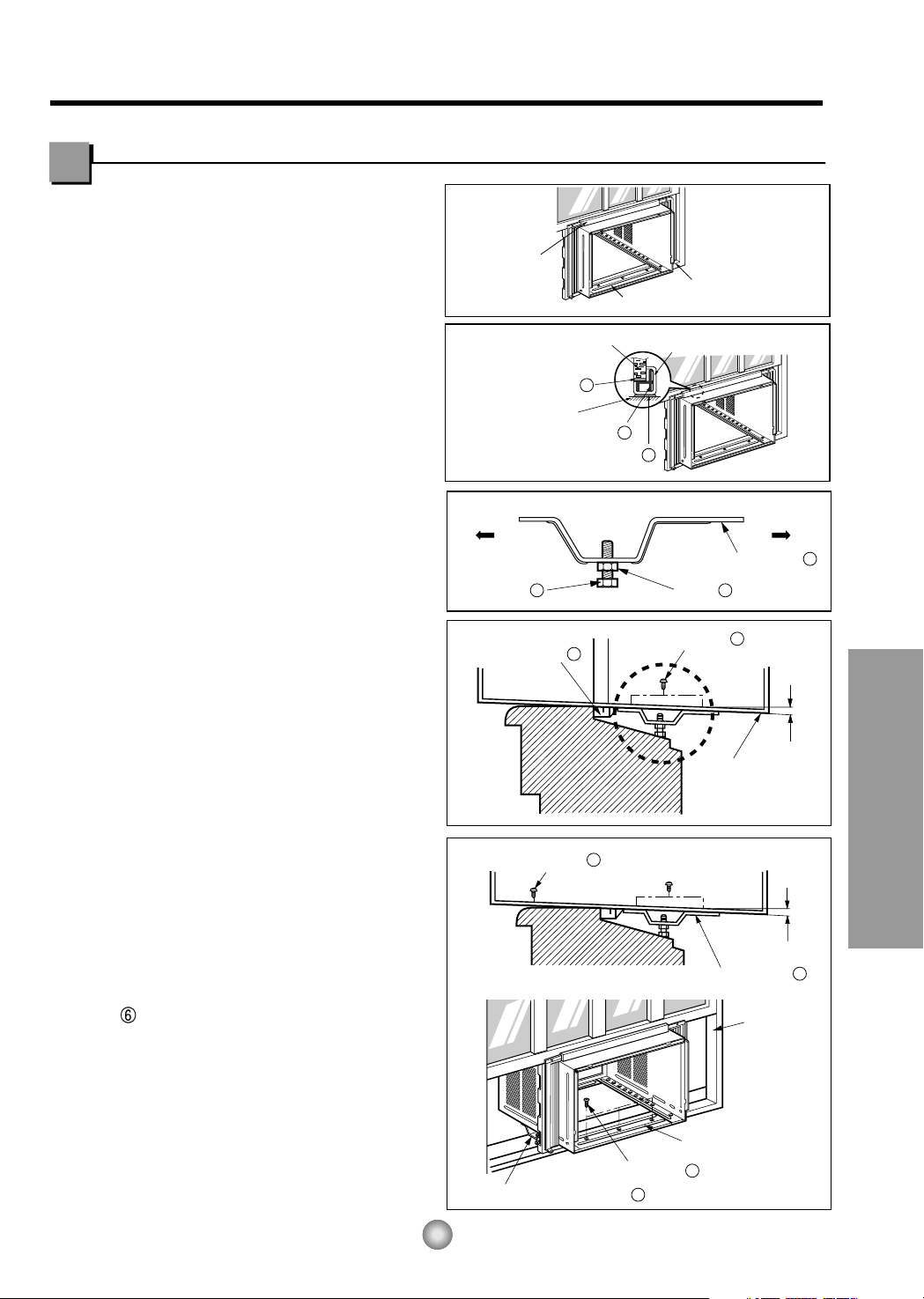
1. Open the window. Mark a line on
center of the window sill (or desired
air conditioner location).
Carefully place the cabinet on the
window sill and align the center mark
on the bottom front with the center
line marked in the window sill.
(See Fig.1)
2. Pull the bottom window sash down
behind the upper guide until it
meets.(See Fig.2)
NOTE:
• Do not pull the window sash down so
tightly that the movement of Frame
Curtain is restricted.
3. Loosely assemble the sill support
using the parts in Fig. 3.
4. Select the position that will place the
sill support near the outer most point
on sill (See Fig. 4)
5. Attach the sill support to the cabinet
track hole in relation to the selected
position using 2 Type A screws in
each support (See Fig. 4).
6. The cabinet should be installed with a
very slight tilt (about 12.7mm(
1
/2"))
downward toward the outside (See
Fig. 5).
Adjust the bolt and the nut of sill
support for balancing the cabinet.
7. Attach the cabinet to the window sill
by driving the screws (Type B)
through the front angle into window
sill.
8. Pull each Frame curtain fully to each
window sash track, and repeat step 2.
Cabinet Installation
Fig. 1
Fig. 2
Fig. 3
Fig. 4
Fig. 5
Type C
7
Screw
Screw
Power cord
Foam-Strip
8
Window locking bracket
10
14
Features and Installation
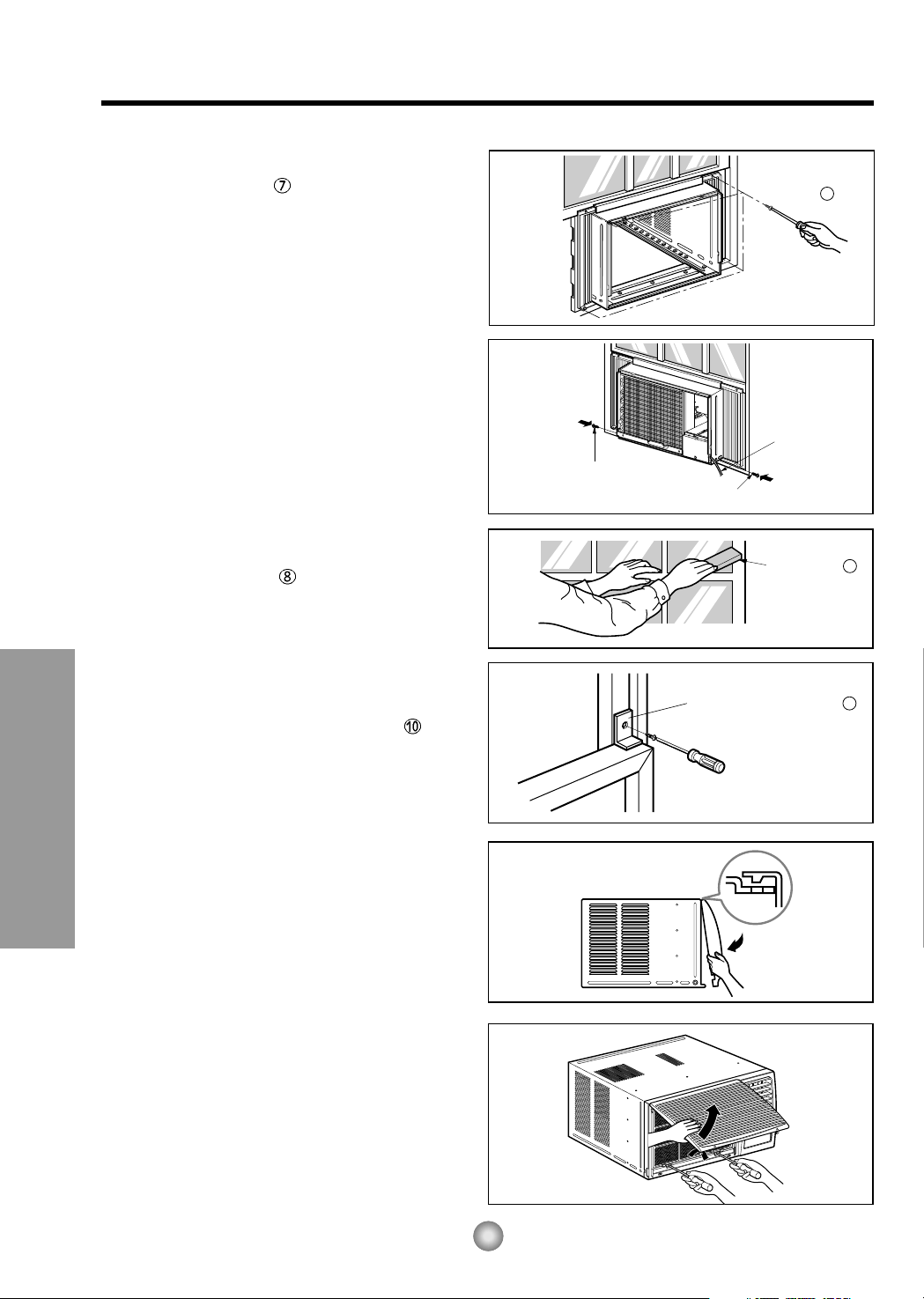
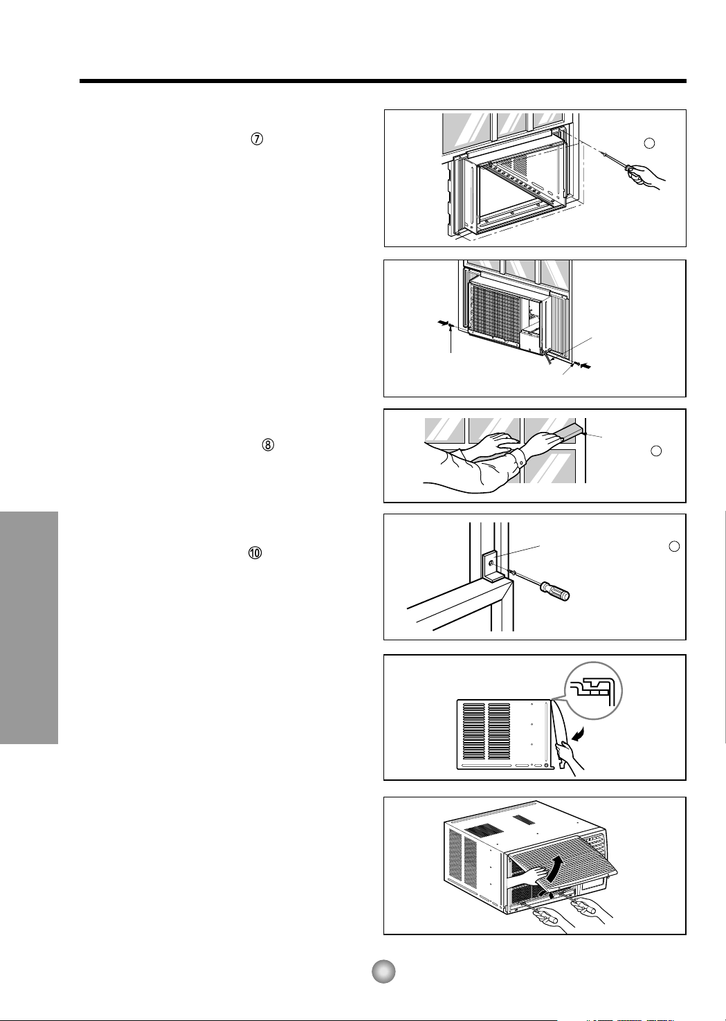
9. Attach each Frame curtain to the window
sash using screws
(Type C). (See Fig. 6)
CAUTION: DO NOT DRILL A HOLE IN THE
BOTTOM PAN.
The unit is designed to operate
with approximately 12.7mm (
1
/
2") of
water in bottom pan.
10. Slide the unit into the cabinet. (See Fig. 7)
CAUTION: For security purposes, reinstall
screws at cabinet's sides.
11. Cut the foam-strip
to the proper length
and insert between the upper window sash
and the lower window sash.
(See Fig. 8)
12. Attach the window locking bracket with
a type C screw. (See Fig. 9)
13. Attach the front grille to the cabinet by
inserting the tabs on the grille into the tabs
on the front of the cabinet. Push the grille
in until it snaps into place. (See Fig.10)
NOTE: Please refer p.8 for setting ventilation
kit.
14. Lift the inlet grille and secure it with two
type two screws through the front grille.
(See Fig. 11)
15. Window installation of room air conditioner
is now completed. See ELECTRICAL DATA
for attaching power cord to electrical outlet.
Fig. 6
Fig. 7
Fig. 8
Fig. 9
Fig. 10
Fig. 11

15
Features and Installation
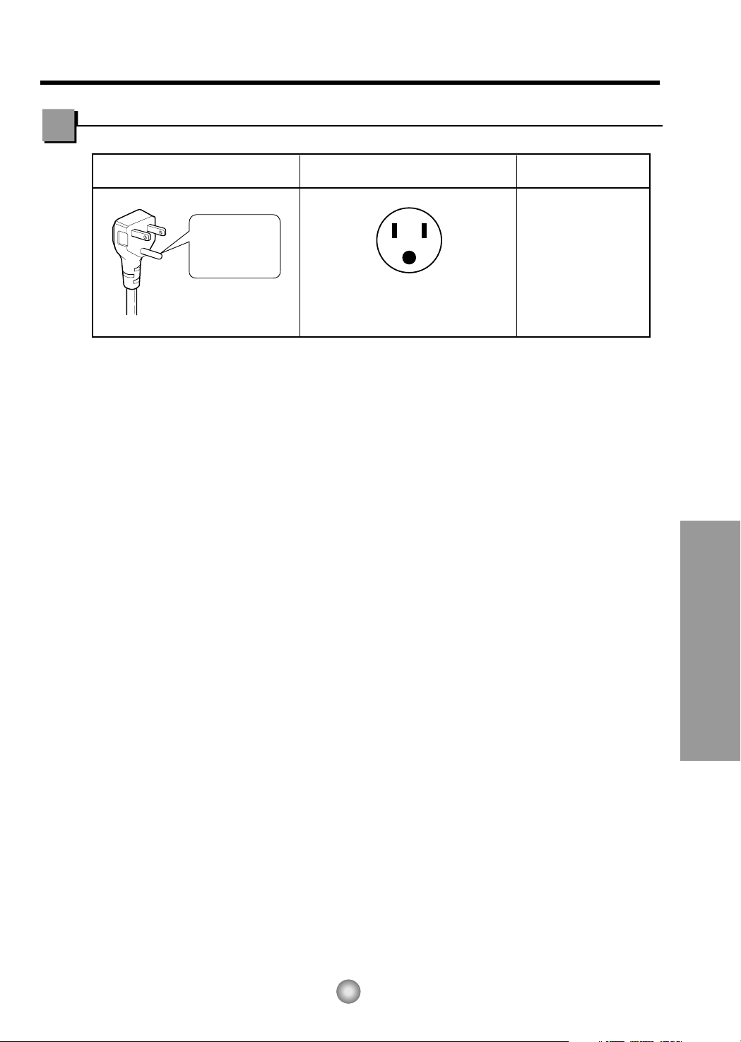
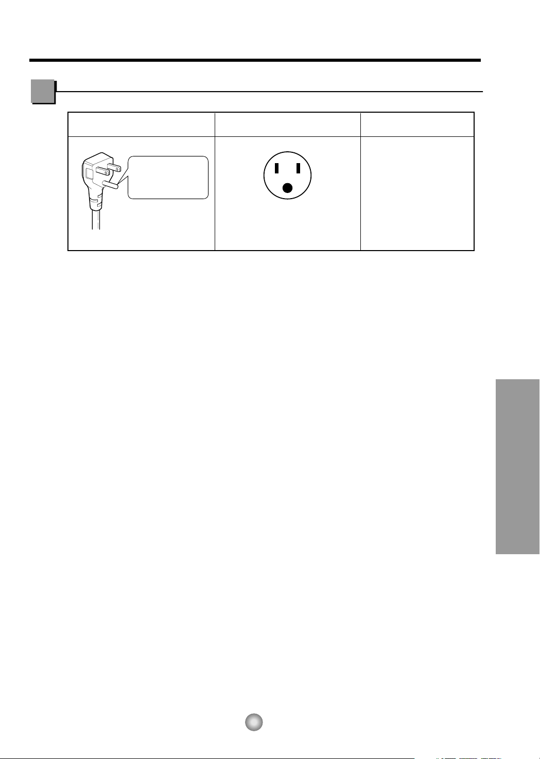
Do not under any
circumstances cut
or remove the
grounding prong
from the plug.
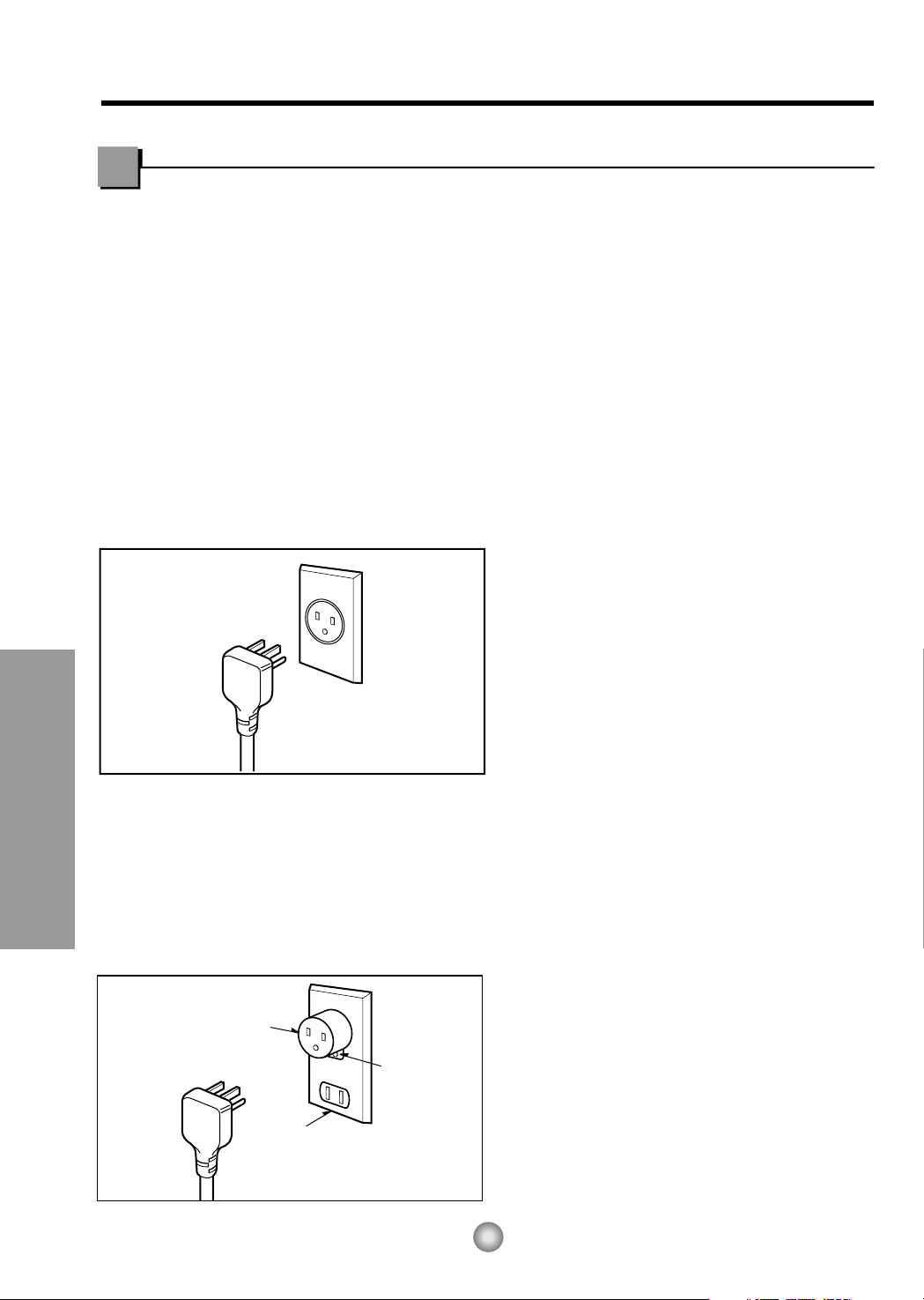
Line Cord Plug Use Wall Receptacle Power Supply
Power supply cord with
3-prong grounding plug
Standard 125V, 3-wire grounding
receptacle rated 15A, 125V AC
Use 15 AMP, time
delay fuse or circuit
breaker.
Electrical Data
USE OF EXTENSION CORDS
Because of potential safety hazards, we strongly discourage the use of an extension cord.
However, if you wish to use an extension cord, use a CSA certified/UL-listed 3-wire (grounding)
extension cord, rated 15A, 125V.
15
Features and Installation
Do not under any
circumstances cut
or remove the
grounding prong
from the plug.
Line Cord Plug Use Wall Receptacle Power Supply
Power supply cord with
3-prong grounding plug
Standard 125V, 3-wire grounding
receptacle rated 15A, 125V AC
Use 15 AMP, time
delay fuse or circuit
breaker.
Electrical Data
USE OF EXTENSION CORDS
Because of potential safety hazards, we strongly discourage the use of an extension cord.
However, if you wish to use an extension cord, use a CSA certified/UL-listed 3-wire (grounding)
extension cord, rated 15A, 125V.
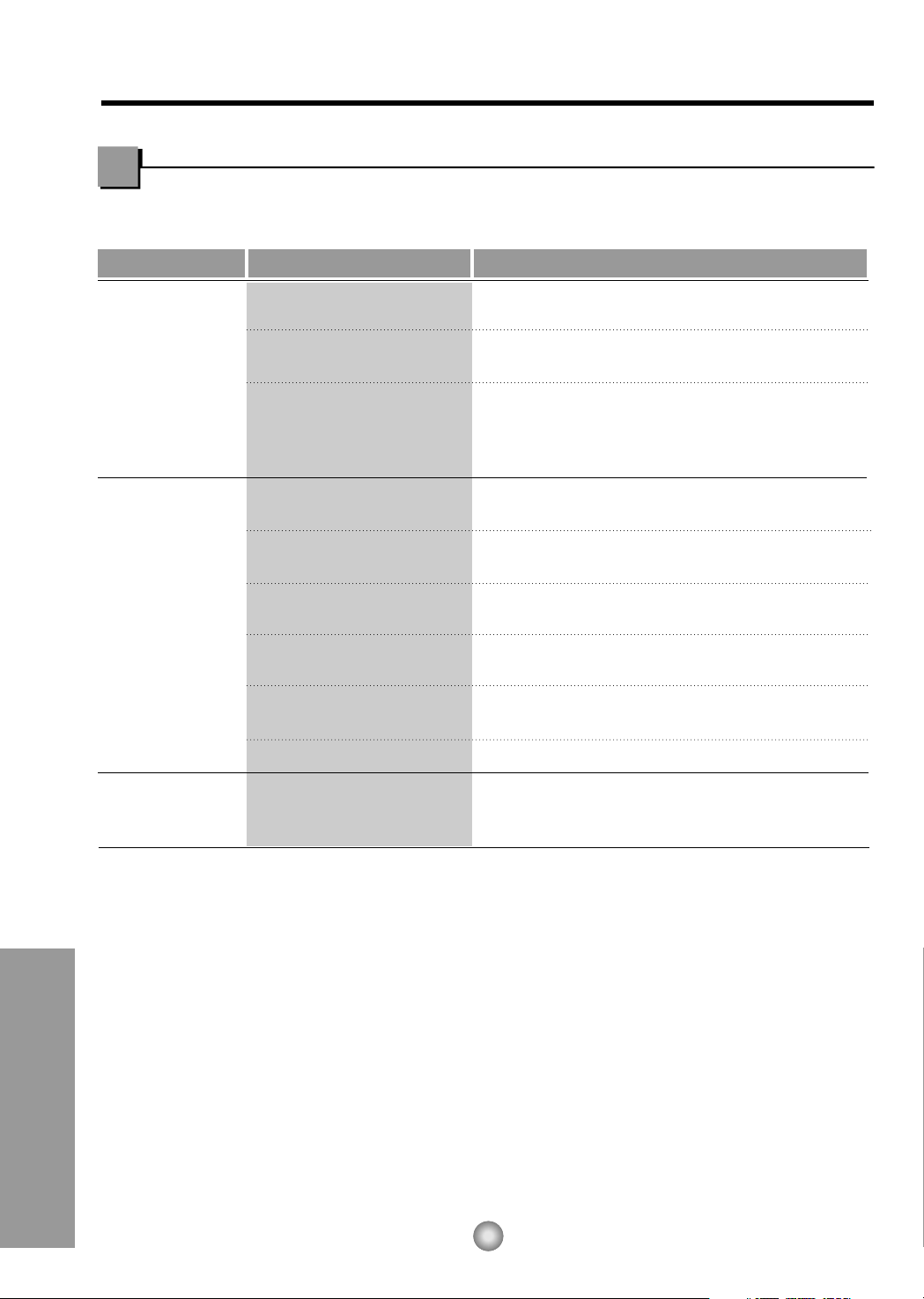
PREFERRED METHOD
Ensure proper ground
exists before use
TEMPORARY METHOD
Adapter plug
Receptacle cover
Metal screw
16
Electrical Safety (Applies to USA and Puerto Rico)
Features and Installation
IMPORTANT
(PLEASE READ CAREFULLY)
FOR THE USER'S PERSONAL SAFETY, THIS
APPLIANCE MUST BE PROPERLY GROUNDED
The power cord of this appliance is equipped with a
three-prong (grounding) plug. Use this with a
standard three-slot (grounding) wall power outlet
(Fig. 12) to minimize the hazard of electric shock.
The customer should have the wall receptacle and
circuit checked by a qualified electrician to make
sure the receptacle is properly grounded.
DO NOT CUT OR REMOVE THE THIRD
(GROUND) PRONG FROM THE POWER
PLUG.
A. SITUATIONS WHERE THE APPLIANCE
WILL BE DISCONNECTED ONLY
OCCASIONALLY:
Because of potential safety hazards, we strongly
discourage the use of an adapter plug. However, if
you wish to use an adapter, a TEMPORARY
CONNECTION may be made. Use UL-listed
adapter, available from most local hardware stores
(Fig. 13). The large slot in the adapter must be
aligned with the large slot in the receptacle to
assure a proper polarity connection.
CAUTION: Attaching the adapter ground terminal to
the wall receptacle cover screw does not ground the
appliance unless the cover screw is metal, and not
insulated, and the wall receptacle is grounded
through the house wiring.
The customer should have the circuit checked by a
qualified electrician to make sure the
receptacle is properly grounded.
Disconnect the power cord from the adapter, using
one hand on each. Otherwise, the adapter ground
terminal might break. DO NOT USE the appliance
with a broken adapter plug.
B. SITUATIONS WHERE THE APPLIANCE
WILL BE DISCONNECTED OFTEN.
Do not use an adapter plug in these situations.
Unplugging the power cord frequently can lead to
an eventual breakage of the ground terminal. The
wall power outlet should be replaced by a three-slot
(grounding) outlet instead.
USE OF EXTENSION CORDS
Because of potential safety hazards, we strongly
discourage the use of an extension cord. However,
if you wish to use an extension cord, use a CSA
certified/UL-listed 3-wire (grounding) extension
cord, rated 15A, 125V.
Fig. 12
Fig. 13

17
Before you call for service...
Before you call for service...
Troubleshooting Tips save time and money!
Review the chart below first and you may not need to call for service.
Models: CW-XC64HU, CW-XC64HK, CW-XC84GU, CW-XC84HK, CW-XC84HU
Normal Operation
• You may hear a pinging noise caused by water being picked up and thrown against the condenser
on rainy days or when the humidity is high. This design feature helps remove moisture and improve
efficiency.
• You may hear the relay click when the compressor cycles on and off.
• Water will collect in the base pan during high humidity or on rainy days. The water may overflow
and drip from the outdoor side of the unit.
• The fan may run even when the compressor does not.
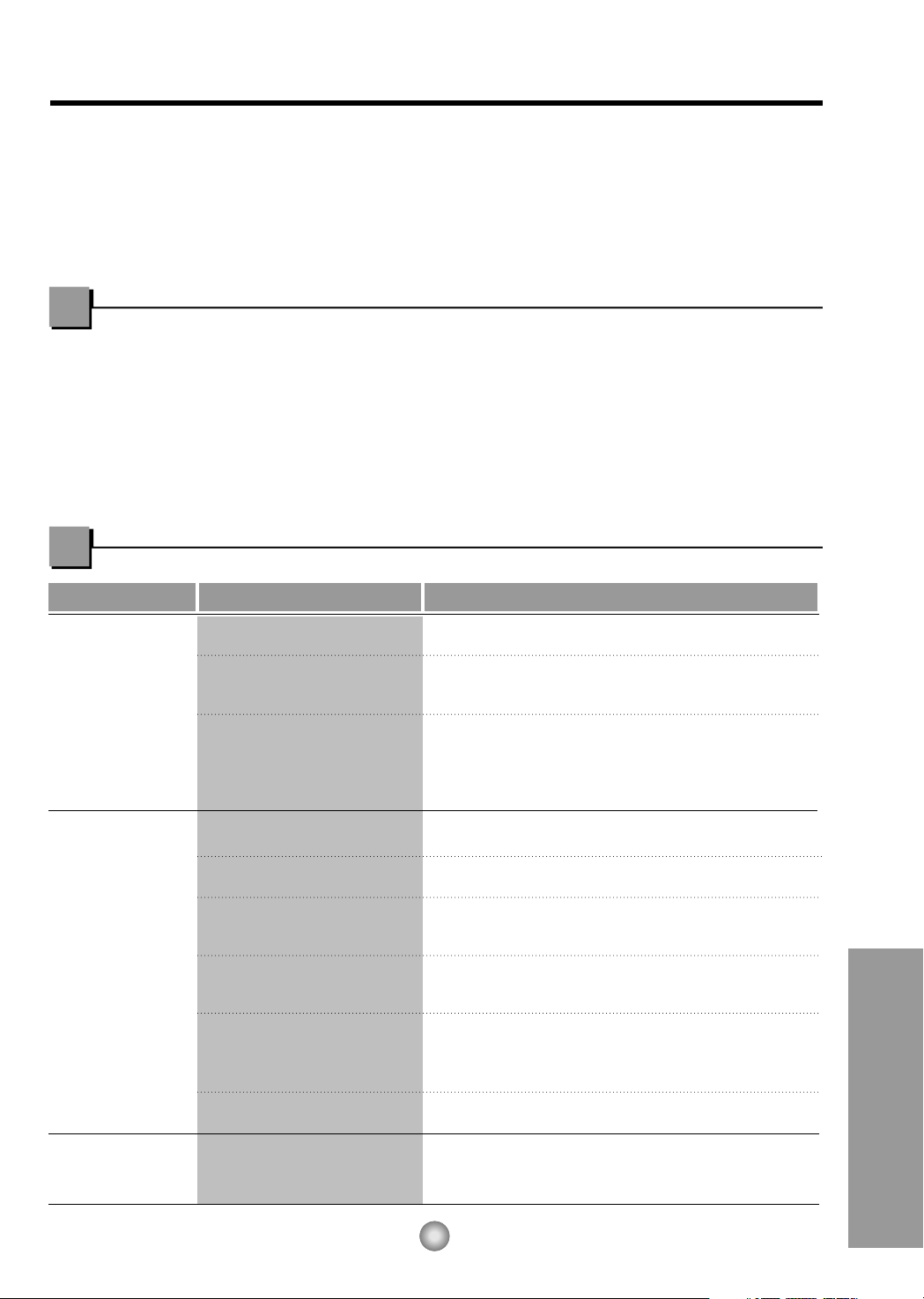
Abnormal Operation
Problem Possible Causes What To Do
■ The air conditioner is
unplugged.
■ The fuse is blown/circuit
breaker is tripped.
■ Power failure.
■ Airflow is restricted.
■ TEMP Control set to a
higher number.
■ The air filter is dirty.
■ The room may have been
hot.
■ Cold air is escaping.
■ Cooling coils have iced up.
■ Ice blocks the air flow and
stops the air conditioner
from cooling the room.
• Make sure the air conditioner plug is pushed
completely into the outlet.
• Check the house fuse/circuit breaker box and
replace the fuse or reset the breaker.
• When power is restored, wait 3 minutes to restart the
air conditioner to prevent tripping of the compressor
overload.
• Make sure there are no curtains, blinds, or furniture
blocking the front of the air conditioner.
• Set the TEMP Control to a lower number.
• Clean the filter at least every 2 weeks.
See the operating instructions section.
• When the air conditioner is first turned on
you need to allow time for the room to cool down.
• Check for open furnace floor registers
and cold air returns.
• Set the air conditioner's vent to the closed position.
• See Air Conditioner Freezing Up below.
• Set the mode control to High Fan at a high
temperature.
Air conditioner
does not start
Air conditioner
does not cool as it
should
Air conditioner
freezing up
18
Before you call for service...
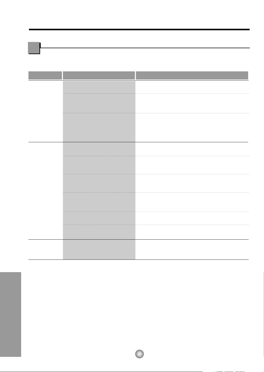
Abnormal Operation
Model: CW-C84GU
Problem Possible Causes What To Do
■ The air conditioner is
unplugged.
■ The fuse is blown/circuit
breaker is tripped.
■ Power failure.
■ Airflow is restricted.
■ The THERMOSTAT may
not be set high enough.
■ The air filter is dirty.
■ The room may have been
hot.
■ Cold air is escaping.
■ Cooling coils have iced up.
■ Ice blocks the air flow and
stops the air conditioner
from cooling the room.
• Make sure the air conditioner plug is inserted
completely into the outlet.
• Check the house fuse/circuit breaker box and
replace the fuse or reset the breaker.
• If power failure occurs, turn the mode control to Off.
When power is restored, wait 3 minutes to restart the
air conditioner to prevent tripping of the compressor
overload.
• Make sure there are no curtains, blinds, or furniture
blocking the front of the air conditioner.
• Turn the knob to a higher number. The highest
setting provides maximum cooling.
• Clean the filter at least every 2 weeks.
See the care and Maintenance section.
• When the air conditioner is first turned on, you need
to allow time for the room to cool down.
• Check for open furnace floor registers and cold air
returns.
• See Air Conditioner Freezing Up below.
• Set the mode control at Med Fan or High Cool with
thermostat at 1 or 2.
Air conditioner
does not start
Air conditioner
does not cool as it
should
Air conditioner
freezing up

19
MEMO
20
Instructions de fonctionnement
Instructions d'installation
Conseils de dépannage
Mesures de sécurité
Mesures de sécurité
Mesures de sécurité ........21
Instructions de
fonctionnement
Les commandes................23
Télécommande..................25
La ventilation .....................26
Ajuster la direction d’air.....26
Comment utiliser le tuyau
d’évacuation ......................26
Nettoyage et entretien
Nettoyage du filtre à air... ..27
Caractéristiques
Caractéristiques ................28
Instructions pour
l’installation
Choisissez le meilleur
emplacement...........................29
Conditions requises pour
l’installation à la fenêtre...........29
Contenu de l’ensemble
d’installation ............................30
Outils requis pour l’installation
......30
Installation du boîtier...............31
Données sur l’électricité..........33
Mesures de sécurité électriques ....
34
Avant de placer un
appel de service...
Fonctionnement normal ...35
Fonctionnement anormal
....35
ENREGISTREMENT
Reportez ici les numéros de modèle et de série.
Unité
N° de série
Ces numéros sont inscrits sur l'étiquette apposée sur le
flanc de chaque unité.
Raison sociale du vendeur
Date d'achat
• Le présent manuel communique de nombreuses et
précieuses informations quant à l'utilisation et à la
maintenance de ce climatiseur. Un entretien préventif
simple se traduit par une longévité accrue du climatiseur,
d'où une importante économie de temps et d'argent.
• Les conseils de dépannage permettent de résoudre les
problèmes les plus courants. La consultation préalable des
Conseils de dépannage peut éviter le recours à un
technicien de réparation.
• Toute intervention (réparation ou maintenance) de cet
appareil doit être confiée à un technicien agréé.
• Ce climatiseur n'est pas destiné à être utilisé sans
surveillance par de jeunes enfants ou des personnes
handicapées.
• Veillez à ne pas laisser de jeunes enfants jouer avec le
climatiseur.
ATTENTION
LISEZ CE MANUEL

Mesures de sécurité
AVERTISSEMENT
21
Mesures de sécurité
Les instructions ci-après doivent être observées dans le but de prévenir tout risque de dommages corporels
ou matériels.
■ L'utilisation non conforme, résultant de la négligence des instructions, est susceptible de provoquer des
dommages corporels ou matériels dont la gravité est signalée par les indications suivantes :
AVERTISSEMENT
: Ce symbole signale un risque de blessure grave, voire mortelle.
ATTENTION
: Ce symbole signale un risque limité aux dommages matériels.
■ Les significations respectives des symboles utilisés dans ce manuel sont indiquées ci-dessous.
Pratique à éviter impérativement
Instruction à observer impérativement
Veillez à brancher correctement
votre appareil.
• Tout mauvais branchement peut
entraîner une surchauffe de votre
appareil et causer électrocution ou
incendie.
Veuillez ne pas mettre en marche
ou éteindre votre appareil en le
branchant ou débranchant.
• Ceci provoquera une surchauffe et un
risque d'électrocution ou d'incendie.
Évitez
d'endommager le cordon
d'alimentation électrique ou d'en
utiliser un non-recommandé.
• Ceci pourrait causer électrocution ou
incendie.
• Si le cordon d'alimentation est endommagé, il
doit être remplacé par le fabricant, un agent
de service ou une personne qualifiée afin
d'éviter tout risque de danger.
Ne modifiez pas la longueur du
cordon d'alimentation et ne
branchez pas votre climatiseur
en commun avec d'autres
appareils sur la même prise.
• Ceci pourrait provoquer un choc
électrique ou un incendie, dû à
une surchauffe.
Ne faites pas fonctionner
l'appareil les mains
mouillées.
• II y a risque d'électrocution.
Ne pas diriger l'air froid
directement sur les
personnes.
• Cela peut un nuire à votre santé.
22
Mesures de sécurité
ATTENTION!
Lorsque le filtre à air doit être
retiré, ne pas toucher les
parties métaliques de
l'appareil intérieur.
• Vous risquez de vous blesser.
Ne pas nettoyer le
climatiseur à grande eau.
• L'eau peut s'infiltrer dans
l'appareil et affecter l'isolement.
Cela peut également provoquer
une électrocution.
Assurer une ample
circulation d'air dans la pièce
si un appareil de chauffage
est utilisé.
• En effet, l'oxygène s'appauvrit
dans ces conditions d'utilisation.
Lorsque l'appareil doit être
nettoyé, couper l'alimentation
et débrancher la prise
d'alimentation ou couper le
disjoncteur.
• Le ventilateur de refroidissement
tournant à grande vitesse dans
l'appareil, cela peut provoquer un
accident.
Ne pas placer une plante
d'intérieur ou un animal
domestique près de l'appareil
en risquant de l'exposer
directement à l'air froid.
• L'animal comme la plante
peuvent en souffrir.
Ne pas se servir de l'appareil
à des fins spéciales.
• Le climatiseur ne doit pas être
utilisé pour protéger certains
appareils de précision, des
aliments, des animaux, des
plantes et des objets d'art. La
qualité risque d'en souffrir.
Ne pas actionner les
dispositifs de commande les
mains mouillées.
• Il y a risque d'électrocution.
Ne pas utiliser d'insecticide à
proximité de l'appareil ni de
produits inflammables.
• L'appareil risque de prendre feu
ou le coffret risque d'être
déformé.
Ne jamais placer d'appareil de
chauffage, etc., près du climatiseur
et notamment où il risque de
recevoir directement l'air froid.
•
La combustion de l'appareil de
chauffage risque d'être
entravée.
POUR UN REFROIDISSEMENT NORMAL
1. Tournez le bouton des fonctions "Operation" à la position de refroidissement élevé "High Cool" ou de
refroidissement faible "Low Cool".
2. Réglez le thermostat à la température désirée 5 (la position du milieu est un bon point de départ). Si la
température ambiante n'est pas satisfaisante après un certain temps, ajustez la position à un degré plus
froid ou plus chaud, au besoin.
POUR UN REFROIDISSEMENT MAXIMAL
1. Tournez le bouton des fonctions "Operation" à la position de refroidissement élevé "High Cool".
2. Réglez le themostat à la position la plus froide, représentée par le plus grand (9) des chiffres.
POUR UN FONCTIONNEMENT PLUS SILENCIEUX
1. Tournez le bouton des fonctions "Operation" au réglage de refroidissement faible "Low Cool".
2. Réglez le thermostat à la température voulue.
23
Instructions de fonctionnement
Instructions de fonctionnement
Selon le modèle, les commandes ressembleront à l'une des suivantes.
Les commandes
Après avoir changé la position du climatiseur de "Cool" (froid) à "Off" (fermé) ou "Fan"
(ventilateur), attendez au moins 3 minutes avant de le remettre à la position "Cool".
Off (Fermé) : Met le climatiseur hors tension.
Med Fan (Ventilateur moyen) : Fait fonctionner le ventilateur à vitesse
moyenne, sans refroidissement.
Low Fan (Ventilateur bas) : Fait fonctionner le ventilateur à basse
vitesse, sans refroidissement.
High Cool (Refroidissement haut) : Refroidit tout en ventilant à haute vitesse.
Med Cool
(Refroidissement moyen)
:
Refroidit tout en ventilant à vitesse moyenne.
Low Cool (Refroidissement bas) : Refroidit tout en ventilant à basse vitesse.
Cette fonction contrôle automatiquement la température de l'air
ambiant. Tournez le bouton en direction des chiffres les plus
grands pour un refroidissement plus puissant. Faites-le pointer
vers les petits chiffres si vous désirez une ambiance moins fraîche.
Plus le chiffre est élevé, plus le refroidissement est puissant.
(ex: plus le numéro est élevé, plus le refroidissement est puissant.)
MISE EN GARDE
Modèle : CW-C84GU
Modèle: CW-XC84HU
Modèles:CW-XC64HK, CW-XC84HK
FAN
COOL
DRY
hr
F
OPERATION
TEMPTEMP
TIMER MODE
OFF/ON
FAN
SPEED
FAN
SPEED
1
8
4
3 2 5
Modèles: CW-XC64HU, CW-XC84GU
TIMER FANECONOMY
COOL
DRY
TIMERTIMER
MODEMODE
OFF/ON
FAN
SPEED
AIR
SWING
AIR
SWING
F
hr
4
1
7
8
3 2 5
4
1
3 6 2 5
8
OPERATION
TEMP
TIMER
AIR
SWING
AIR
SWING
FANECONOMY
COOL
DRY
TIMERTIMER
MODEMODE
OFF/ON
F
hr
FAN
SPEED
4
1
8
3 2 5
OPERATION
TEMP
24
Instructions de fonctionnement
ALIMENTATION
• Pour mettre l'appareil en marche (ON),
pressez ce bouton. Pour éteindre I'appareil
(OFF), pressez de nouveau sur le bouton.
• Ce bouton a priorité sur tous les autres.
• Quand vous mettez I'appareil en marche la
première fois, il est réglé au mode High
Cool et à la température de 72˚F (22˚C).
REFROIDISSEMENT/VENTILATEUR
• Chaque fois que vous pressez ce bouton
COOL, FAN et DRY alterneront.
(Modèles: CW-XC64HK, CW-XC84HK)
• Chaque fois que vous pressez ce bouton
COOL, ECONOMY, FAN et DRY
alterneront.
(Modèles: CW-XC64HU, CW-XC84HU,
CW-XC84GU)
MINUTERIE MARCHE/ARRÊT
• Chaque fois que vous pressez ce bouton la
minuterie se règle comme suit: (1 heure →
2 heures → 3 heures → 4 heures →
5 heures → 6 heures → 7 heures→
8 heures → 9 heures → 10 heures →
11 heures → 12 heures → 0).
• La température de réglage augmentera de
2˚F (1˚C) 30 minutes plus tard et encore de
2˚F (1˚C) 30 minutes plus tard.
VITESSE DE VENTILATEUR
• Chaque fois que vous appuyez sur ce
bouton, le réglage se fait comme suit;
{Élevée (F3) → Basse (F1) → Moyenne
(F2) → Élevée (F3)...}.
RÉGLAGE DE LA TEMPÉRATURE
• Ce bouton peut contrôler automatiquement la
température de la pièce. On peut régler la
température dans une gamme de 60˚F à 86˚F par
tranche de 1˚F (16˚C à 30˚C par tranche de 1˚C).
Choisissez un chiffre plus bas pour une
température de la pièce plus basse.
ÉCONOMIE D'ÉNERGIE
(Modèles: CW-XC64HK, CW-XC84HK)
• Le ventilateur s'arrête lorsque le compresseur
cesse de refroidir.
• Environ toutes les 3 minutes, le ventilateur se
mettra en marche et vérifiera l'air de la pièce pour
déterminer si un refroidissement est nécessaire.
ORIENTATION AUTOMATIQUE
• Ce bouton peut contrôler automatiquement la
direction de l'air.
CAPTEUR DU SIGNAL DE LA TÉLÉCOMMANDE
Les commandes
OPERATION
TEMP
TIMER
MODE
ECONOMY
FAN SPEED
1
3
2 4
6
5
Modèle: CW-XC84HU
Modèles: CW-XC64HU, CW-XC64HK
CW-XC84GU, CW-XC84HK
OPERATION
TEMP
TIMER
AIR
SWING
MODE
ECONOMY
FAN SPEED
1
3
2 4
6
5
7
25
Instructions de fonctionnement
ALIMENTATION
•
Pour mettre l'appareil en marche (ON), pressez ce bouton.
Pour éteindre I'appareil (OFF), pressez de nouveau sur le
bouton.
• Ce bouton a priorité sur tous les autres.
• Quand vous mettez I'appareil en marche la première fois,
il est réglé au mode High Cool et à la température de
72˚F(22˚C).
REFROIDISSEMENT/VENTILATEUR
• Chaque fois que vous pressez ce bouton COOL, FAN et
DRY alterneront. (Modèles: CW-XC64HK, CW-XC84HK)
• Chaque fois que vous pressez ce bouton
COOL, ECONOMY, FAN et DRY alterneront.
(Modèles: CW-XC64HU, CW-XC84HU, CW-XC84GU)
MINUTERIE MARCHE/ARRÊT
- ARRÊT DU FONCTIONNEMENT
• Chaque fois que vous pressez ce bouton, lorsque
I'appareil fonctionne, la minuterie se règle comme suit:
(1 heure → 2 heures → 3 heures → 4 heures → 5 heures
→ 6 heures → 7 heures → 8 heures → 9 heures →
10 heures → 11 heures → 12 heures → 0)
•
La température de réglage augmentera de 2˚F(1˚C) 30
minutes plus tard et encore de 2˚F(1˚C) 30 minutes plus tard.
- DÉBUT DU FONCTIONNEMENT
• Chaque fois que vous pressez ce bouton, lorsque
I'appareil fonctionne, la minuterie se règle comme suit:
(1 heure → 2 heures → 3 heures → 4 heures → 5 heures
→ 6 heures → 7 heures → 8 heures → 9 heures →
10 heures → 11 heures → 12 heures → 0)
VITESSE DE VENTILATEUR
• Chaque fois que vous appuyez sur ce bouton, le réglage se
fait comme suit. {Élevée (F3) → Basse (F1) → Moyenne (F2)
→ Élevée (F3)...}.
RÉGLAGE DE LA TEMPÉRATURE
• Ce bouton peut contrôler automatiquement la
température de la pièce. On peut régler la température
dans une gamme de 60˚F à 86˚F par tranche de 2˚F
(16˚C à 30˚C par tranche de 1˚C). Choisissez un chiffre
plus bas pour une température de la pièce plus basse.
ÉCONOMIE D'ÉNERGIE
Lors d'une pression sur ce bouton, le ventilateur s'arrête
lorsque le compresseur cesse de refroidir.
• Environ toutes les 3 minutes, le ventilateur se mettra en
marche et vérifiera l'air de la pièce pour déterminer si un
refroidissement est nécessaire.
ORIENTATION AUTOMATIQUE
• Ce bouton peut contrôler automatiquement la direction de
l'air.
MODE SEC
• Quand l’appareil est en mode sec, le ventilateur tourne à
basse vitesse. Le ventilateur s’arrête quand le
compresseur cesse de refroidir.
Environ toutes les 3 minutes, le ventilateur se mettra en
marche et l’appareil vérifiera l’air de la pièce pour
effectuer un autoréglage.
MISE EN GARDE:
LA TÉLÉCOMMANDE NE FONCTIONNERA PAS CORRECTEMENT SI UNE LUMIÈRE FRAPPE LA FENÊTRE DU
CAPTEUR DU CLIMATISEUR OU S'IL Y A DES OBSTACLES ENTRE LA TÉLÉCOMMANDE ET LE CLIMATISEUR.
Télécommande
Instructions de fonctionnement
Pièce
B
Pièce A
Tuyau
d'évacuation
Capuchon d'évacuation
VENTCLOSE
OPEN
Réglage manuel
Réglage manuel
Réglage par
télécommande
(Modele:CW-XC84HU)
AppuyezPendez
O
F
F
/
O
N
O
P
E
R
A
T
I
O
N
T
E
M
P
/
T
I
M
E
R
C
O
O
L
F
A
N
H
I
G
H
M
E
D
L
O
W
M
O
D
E
F
A
N
S
P
E
E
D
S
E
T
T
I
M
E
R
S
E
T
/
C
A
N
C
E
L
A
I
R
S
W
I
N
G
E
C
O
N
O
M
Y
h
r
F
W
i
r
e
l
e
s
s
R
e
m
o
t
e
C
o
n
t
r
o
l
Retirez le bouchon de
caoutchouc
Schéma 4
Schéma 3
Schéma 2
Schéma 1
PLATEAU DE
VIDANGE
TUYAU D'ÉVACUATION
Le diamètre intérieur est
de 17 mm (5/8 po)
BOÎTIER
VIS
O
F
F
/
O
N
O
P
E
R
A
T
I
O
N
T
E
P
/
T
I
C
O
O
L
F
A
N
H
I
G
H
M
E
D
L
O
W
M
O
E
F
A
N
S
P
E
E
D
S
E
T
T
I
M
E
R
S
E
T
/
C
N
E
A
I
R
E
C
O
N
O
M
Y
F
W
i
r
e
l
e
s
s
R
e
m
o
t
e
C
o
n
t
r
o
l
26
Commandes supplémentaires et renseignements importants.
La ventilation
Le levier de ventilation doit être en position FERMÉE (“CLOSE”) afin de conserver les
meilleures conditions de refroidissement. Lorsque vous avez besoin d'air frais dans la
pièce, réglez le levier à la position OUVERTE (“OPEN”). Le registre est ouvert et l'air
ambiant est expulsé à l'extérieur.
REMARQUE: Avant de vous servir de la fonction de ventilation, et avant
l'installation du grillage frontal, abaissez la pièce jusqu'à ce
qu'elle soit du même niveau que la pièce .
Ajuster la direction d'air
En vous servant des volets horizontal et vertical, vous pouvez diriger la circulation d'air là où vous le désirez.
• CONTRÔLE HORIZONTAL DE LA DIRECTION D'AIR
• CONTRÔLE VERTICAL DE LA DIRECTION D'AIR
En vous servant des volets horizontal et
vertical, vous pouvez diriger la circulation
d'air là où vous le désirez.
Ajustez la direction horizontale de l'air en tournant
manuellement le volet vertical vers la droite ou la
gauche ou en utilisant la télécommande.
Comment utiliser le tuyau d’évacuation
En temps humide, l'eau peut causer le débordement du PLATEAU.
Pour évacuer l'eau, enlevez le capuchon d'évacuation et fixez le tuyau d'évacuation à l'orifice
arrière du PLATEAU. Insérez le tuyau d'évacuation dans le trou en appuyant, tout en évitant les
ailettes. (Schéma 1)
Facultatif (CW3H02502C)
1. Retirez le bouchon de caoutchouc et glissez le châssis
en-dehors du boîtier.
(
Référez-vous au schéma
2)
2. Installez le plateau de vidange en dessous du coin du boîtier,
d’où vous avez retiré le bouchon, avec 4 (ou 2) vis.
(Référez-vous au schéma 3)
3. Branchez le tuyau d’évacuation sur l’évacuation située en bas
du plateau de vidange. Pour satisfaire pleinement vos besoins,
vous pouvez acheter le tuyau d’évacuation ou le tubage dans
votre région. (Le tuyau d’évacuation n’est pas fourni.)
(Référez-vous au schéma 3)
4. Sélectionnez le branchement le plus approprié en choisissant
parmi les schémas suivants (en tenant compte de l’orifice de
l’appareil) pour que le plateau de vidange s’adapte à votre
appareil. (Référez-vous au schéma 3)
5. Replacez le châssis dans le boîtier.
Réinstallez les vis de fixation du boîtier. Fixez le boîtier au
châssis à l'aide des vis de fixation. (Référez-vous au schéma 4)
Instructions de fonctionnement
27
FERMEZ LE CLIMATISEUR ET DÉBRANCHEZ LA FICHE DE LA PRISE DE COURANT.
Nettoyage et entretien
Nettoyage du filtre à air
Le filtre à air derrière la grille frontale doit être vérifié et nettoyé au moins toutes les 2
semaines ou plus souvent si nécessaire.
POUR L'ENLEVER :
1. Ouvrez la grille vers le haut en soulevant le bas de la grille ou vers le bas en tirant le
haut de la grille.
2. En utilisant la languette, soulevez délicatement le filtre et tirez-le vers le haut ou vers le
bas.
3. Nettoyez le filtre avec de l’eau chaude et savonneuse à moins de 40°C (104°F).
4. Rincez et essuyez délicatement le filtre et laissez-le sécher avant de le remettre en
place.
ATTENTION: Ne faites pas fonctionner le climatiseur sans un filtre parce que la saleté
l’obstruerait et réduirait ses performances.
Comment insérer les piles
1. Retirez le couvercle en le glissant vers le
bas.
2. Mettez deux piles neuves AAA dans leur
logement en respectant la polarité.
3. Remettez le couvercle dans sa glissière.
• Ne pas utiliser de piles
rechargeables dans la
télécommande.
• Si vous comptez ne pas
utiliser l'appareil pour une
longue période, retirez les
piles de la télécommande.

Instructions d'installation
28
Apprendre le nom des pièces avant l'installation vous aidera à mieux comprendre le
processus d'installation.
Caractéristiques
Caractéristiques
F
A
N
E
C
O
N
O
M
YC
O
O
L
D
R
Y
T
I
M
E
R
T
I
M
E
R
T
I
M
E
R
M
O
D
E
M
O
D
E
O
F
F
/
O
N
F
h
r
F
A
N
S
P
E
E
D
A
I
R
S
W
I
N
G
A
I
R
S
W
I
N
G
BOÎTIER
GRILLAGE
FRONTAL
FILTRE À AIR
PRISE D'ADMISSION D'AIR
(GRILLAGE DE LA PRISE)
DÉCHARGE D'AIR
DÉFLECTEUR D'AIR HORIZONTAL
(VOLET VERTICAL)
VOLET VERTICAL
DÉFLECTEUR D'AIR VERTICAL
(VOLET HORIZONTAL)
ÉVAPORATEUR
FIL D'ALIMENTATION
PLATEAU DE LA BASE
CONDENSEUR
COMPRESSEUR
ATTACHE
FIL D'ALIMENTATION
PLATEAU DE LA BASE
CONDENSEUR
COMPRESSEUR
ATTACHE
FIL D'ALIMENTATION
PLATEAU DE LA BASE
CONDENSEUR
COMPRESSEUR
ATTACHE
PANNEAU DES
COMMANDES
TÉLÉCOMMANDE
TÉLÉCOMMANDE
ÉVAPORATEUR
PANNEAU DES
COMMANDES
ÉVAPORATEUR
PANNEAU DES
COMMANDES
Modèles: CW-XC84HU
Modèle: CW-C84GU
Modèles: CW-XC64HK
CW-XC84HK
CW-XC64HU
CW-XC84GU

Mur intérieur
Rebord
De 55,88 à 91,44 cm
(22 à 36 po)
12,7 à 31,8 mm
(1/2 à 1 1/4 po)
Dénivellation
Appui-fenêtre
Extérieur
47 cm (18 1/2 po)
(Sans panneaux coulissants)
Environ 12,7 mm (1/2 po)
76,2 - 152,4 cm
(30 - 60 po)
Support
Air refroidi
Clôture
Plus que 50,8 cm (20 po)
Rayonnement
de la chaleur
Min. de 38 cm (15 po)
(Avec panneaux coulissants)
29
Instructions pour l'installation
Instructions d'installation
Choisissez le meilleur emplacement
1. Afin d'empêcher les vibrations et le bruit,
installez solidement l'appareil.
2. Installez le climatiseur là où le soleil ne brillera
pas directement dessus.
3. L'extérieur du boîtier doit sortir d'environ 28 cm
(11 po) et il ne doit pas y avoir d'obstacles, tels
qu'un mur ou une clôture, à une distance d'au
moins 50,8 cm (20 po) de l'arrière du boîtier;
cette distance minimale permet une propagation
adéquate de la chaleur du condenseur.
Si vous bloquez le rayonnement de la chaleur à
l'extérieur, la capacité de refroidissement de
l'appareil en sera grandement réduite.
AVERTISSEMENT : Tous les louvres sur les côtés du boîtier doivent se trouver à I'extérieur du
bâtiment.
4. Faites pencher légèrement le climatiseur de façon à ce que l'arrière soit un peu plus bas que
l'avant - d'environ 12,7 mm (1/2 po). Ceci aidera à évacuer l'eau condensée vers l'extérieur.
5. Laissez une distance d'environ 76,2 à 152,4 cm (30 à 60 po) entre le plancher et la base du
climatiseur.
Conditions requises pour l'installation à la fenêtre
NOTA: Toutes les pièces de support doivent être fortifées en bois ferme, maçonnerie ou métal.
Cet appareil a été conçu pour être installé dans
des fenêtres doubles à guillotine dont la largeur
d'ouverture varie entre 55,88 cm et 91,44 cm
(22 po et 36 po). Le châssis de la fenêtre du haut
et celui du bas doivent s'ouvrir suffisamment pour
permettre une ouverture verticale de 38 cm (15 po)
à partir du bas du châssis supérieur jusqu'au
rebord de la fenêtre.
N° NOM DE LA PIÈCE QTÉ
1 PANNEAUX COULISSANTS 2
2
ANCRAGE DE L'APPUI-FENÊTRE
2
3 BOULON 2
4 ÉCROU 2
5 VIS (TYPE A) 10mm (25/64 po) 16
6 VIS (TYPE B) 3
7 VIS (TYPE C) 5
8
BANDE DE MOUSSE
1
9
FIXATION DE MOUSSE DE TYPE PE
(466 mm x 10 mm x 2 mm)
1
10
PATTE DE FIXATION
1
11
FIXATION DE MOUSSE DE TYPE PE (920 mm x 30 mm x 2 mm)
1
12 TUYAU D'ÉVACUATION 1
Instructions d'installation
9
5
5
5
(Type A)
(Type A)
Guide inférieur
11
Vis d'expédition
Guide inférieur
1
2 3 4
8 11
12
9
765
10
PRÉPARATIFS DU CHÂSSIS
1. Retirez les vis qui retiennent le boîtier sur les
deux côtés et par en arrière.
2. Glissez l'appareil en-dehors du boîtier en
agrippant la poignée du plateau de la base et
en le tirant vers l'avant, tout en le tenant
solidement.
3. Découpez la bande scellante du rebord de la
fenêtre à la longueur appropriée.
Décollez l'endos et attachez la bande de
mousse de type PE sous le rebord de la
fenêtre.
4. Enlevez la bande scellante de fixation de
mousse , et attachez-la au fond du guide
supérieur.
5. Joignez le guide supérieur au-dessus du
boîtier à l'aide de 3 vis de type A. Insérez les
vis par le dessous.
6. Insérez les panneaux coulissants dans le
guide supérieur dans les cadrages-guide.
7. Faire fixer les panneaux coulissants au
châssis avec 4 vis de type A.
30
Outils requis pour l’installation
Contenu de l'ensemble d'installation
TOURNEVIS (+,-), RÈGLE, COUTEAU, MARTEAU, CRAYON, NIVEAU À BULLE D'AIR
D5,1 mm (3/16 po) / 16 mm (5/8 po)
D4,1 mm (5/32 po) / 16 mm (5/8 po)
■ La barre de retenue
se trouve dans
l'emballage.
31
Instructions d'installation
Glissière de la fenêtre
Guide supérieur
Rebord de la fenêtre
Angle frontal
Guide supérieur
Panneaux coulissants
1
Fixation de mousse de type PE
9
Fixation de
mousse de type PE
11
Boîtier
Intérieur Extérieur
Intérieur Extérieur
Boîtier
Approx. 12,7 mm (1/2 po)
Ancrage de l'appui-fenêtre
2
Écrou
4
Boulon
3
Cadrage guide
9
Approx. 12,7 mm (1/2 po)
Vis (Type B)
6
Ancrage de l'appui-fenêtre
2
Vis (Type A)
5
Rainure du
châssis
Angle frontal
Vis (Type B)
6
Ancrage de l'appui-fenêtre
2
1. Ouvrez la fenêtre. Faites une marque au
centre du rebord de la fenêtre (là où vous voulez
installer l'appareil).
Placez soigneusement le boîtier sur le rebord de la
fenêtre et alignez la marque du centre de la partie
avant, sous le boîtier, avec la ligne centrale déjà
inscrite sur le rebord. (Référez-vous au schéma 1.)
2. Descendez le châssis de la fenêtre du bas derrière
le guide supérieur jusqu'à ce que les deux se
rencontrent. (Référez-vous au schéma 2.)
REMARQUE:
• Ne descendez pas trop le châssis de la fenêtre de
façon à ne pas bloquer le mouvement des panneaux
coulissants.
3.
Assemblez l'ancrage de l'appui-fenêtre à l'aide des
pièces illustrées au schéma 3 mais ne les serrez pas.
4. Choisissez la position qui placera l'ancrage de
l'appui-fenêtre près du point le plus éloigné sur
l'appui-fenêtre. (Référez-vous au schéma 4.)
5. Attachez l'ancrage de I'appui-fenêtre aux positions
indiquées avec deux vis de type A. (Référez-vous
au schéma 4.)
6. Installez le boîtier en le penchant légèrement -
d'environ 12,7 mm (1/2 po) - vers l'extérieur.
(Référez-vous au schéma 5.)
Ajustez le boulon et l'écrou de l'appui-fenêtre de
façon à équilibrer le boîtier.
7. Attachez le boîtier au rebord de la fenêtre en vissant
les vis (Type B) à travers l'angle frontal, dans le
rebord.
8. Tirez pleinement sur les panneaux coulissants
jusqu'à ce qu'ils appuient sur chacunes des rainures
du châssis, puis répétez l'étape 2.
Installation du boîtier
Schéma 1
Schéma 2
Schéma 3
Schéma 4
Schéma 5
Vis
Vis
Fil d'alimentation
Type C
7
Bande de
mousse
8
Verrouillage de la fenêtre
12
32
Instructions d'installation
9. Attachez chaque panneaux coulissant au châssis
de la fenêtre à l'aide des vis (Type C).
(Référez-vous au schéma 6.)
MISE EN GARDE: NE PERCEZ PAS UN TROU AU
FOND DU PLATEAU
. L'appareil a été conçu pour
fonctionner avec environ 12,7 mm (1/2 po) d'eau
dans le fond du plateau.
10. Faites glisser le châssis dans le boîtier.
(Référez-vous au schéma 7.)
MISE EN GARDE: À des fins sécuritaires,
réinstallez les vis de sur les
côtés du boîtier.
11. Coupez la bande de mousse à la bonne
longueur et insérez-la entre le châssis de la
fenêtre du haut et celui du bas. (Référez-vous
au schéma 8.)
12.
Joignez la patte de fixation à l'aide d'une vis
de type C. (Référez-vous au schéma 9.)
13. Attachez le grillage frontal au boîtier en
introduisant les onglets du grillage dans ceux du
boîtier. Poussez le grillage jusqu'à ce qu'il
s'enclenche en position. (Référez-vous au
schéma 10.)
14. Levez le grillage de la prise et fixez-le au
grillage frontal avec une vis de type A.
(Référez-vous au schéma 11.)
15. L'installation du climatiseur de fenêtre est
maintenant achevée. Voir DONNÉES SUR
L'ÉLECTRICITÉ pour brancher le cordon
d'alimentation à la prise de courant.
Schéma 6
Schéma 7
Schéma 8
Schéma 9
Schéma 10
Schéma 11
33
Instructions d'installation
Ne coupez ni enlevez
en aucun cas la broche
de mise à la masse de
la fiche.
Fiche du cordon d'alimentation Utilisez ce type de prise murale Source d'alimentation
Fil d'alimentation avec
fiche à 3 broches de type
mise à la masse
Prise standard de 125 V
à 3 fils avec mise à la masse,
capacité de 15 A,125 V c.a.
Utilisez un fusible à
retardement de 15 A
ou un disjoncteur.
Données sur l'électricité
UTILISATION DE CORDONS PROLONGATEURS
À cause des dangers potentiels nous vous déconseillons fortement l'utilisation de cordons prolongateurs. Toutefois, si
vous tenez à les utiliser, servez-vous d’un cordon prolongateur à 3 fils homologué par I'ACNOR, dont la capacité est
de 15 A, 125 V.

34
Mesures de sécurité électriques (Pour les États -Unis seulement)
Instructions d'installation
MÉTHODE RECOMMANDÉE
ASSUREZ-VOUS D'AVOIR UNE
MISE À LA MASSE ADÉQUATE
AVANT D'UTILISER CET APPAREIL
MÉTHODE TEMPORAIRE
Fiche d'adaptation
Couvercle de la prise
Vis en métal
IMPORTANT
(VEUILLEZ LIRE ATTENTIVEMENT)
POUR VOTRE PROPRE SÉCURITÉ, CET
APPAREIL DOIT ÊTRE ADÉQUATEMENT MIS À
LA MASSE.
Le fil d'alimentation de cet appareil est muni
d'une fiche à trois broches (dont une de mise à la
masse). Branchez cette fiche dans une prise à
trois ouvertures standard (schéma 12) afin de
réduire les risques de choc électrique ou
d'incendie.
Le consommateur devrait faire vérifier sa prise
de courant par un électricien qualifié afin de
s'assurer que celle-ci soit bien mise à la masse.
NE TENTEZ PAS D'ANNULER LA TROISIÈME
BROCHE (DE MISE À LA MASSE) EN LA
COUPANT OU L'ARRACHANT DE LA FICHE.
A. SITUATIONS OÙ L'APPAREIL N'AURA
PAS À ÊTRE DÉBRANCHÉ SOUVENT
À cause des dangers potentiels, nous ne vous
conseillons pas d'utiliser la fiche d'adaptation.
Toutefois, si vous tenez à l'utiliser, vous
pouvez faire un RACCORD TEMPORAIRE.
Servez-vous d'un adaptateur approuvé par
l'ACNOR, que vous trouverez dans toutes les
bonnes quincailleries (schéma 13).
Assurez-vous d'aligner la fente large de
l'adaptateur avec la fente large de la prise afin
que la polarité soit respectée.
ATTENTION: Le fait de relier la borne de mise
à la masse de l'adaptateur à la vis du
couvercle de la prise ne constitue pas une
mise à la masse adéquate, à moins que la vis
soit en métal, qu'elle ne soit pas isolée et que
la prise soit mise à la masse par le filage de la
maison. Le consommateur devrait faire vérifier
la prise par un électricien qualifié afin de
s'assurer qu'elle soit bien mise à la masse.
Débranchez le fil d'alimentation de l'adaptateur
en déposant solidement une main sur chacun
d'eux. Si vous ne procédez pas ainsi, la borne
de mise à la masse peut se briser.
N'UTILISEZ PAS cet appareil si l'adaptateur
est brisé.
B. SITUATIONS OÙ L'APPAREIL DEVRA
ÊTRE DÉBRANCHÉ FRÉQUEMMENT
N'utilisez pas d'adaptateur dans ces situations.
Le fait de débrancher souvent le fil
d'alimentation peut éventuellement faire briser
la borne de mise à la masse.
Remplacez votre prise de courant désuète par
une prise à trois fentes avec mise à la masse.
L'UTILISATION DE CORDONS
PROLONGATEURS
À cause des dangers potentiels nous vous
déconseillons fortement l'utilisation de cordons
prolongateurs. Toutefois, si vous tenez à les
utiliser, servez-vous d'un cordon prolongateur
à 3 fils homologué par l'ACNOR, dont la
capacité est de 15 A, 125 V.
Schéma 12
Schéma 13
35
Avant de placer un appel de service...
Conseils de dépannage
Quelques conseils pour le dépannage:
Épargnez temps et argent! Consultez le tableau ci-dessous et vous éviterez peut-être un
appel de service coûteux.
Fonctionnement normal
•
Il se peut que vous entendiez un cliquettement causé par l'eau qui est soulevée et projetée contre le
condensateur lors des jours de pluie ou lorsque le taux d'humidité est élevé. Cette caractéristique
sert à réduire I'humidité et améliorer l'efficacité de I'appareil.
• Il se peut que vous entendiez le thermostat émettre des déclics lorsque le compresseur se met
en/hors fonction.
• L'eau s'accumulera dans le plateau lors des jours très humides ou des jours de pluie. L'eau peut
déborder et s'égoutter à l'extérieur de l'appareil.
• Le ventilateur peut fonctionner même si le compresseur est inactif.
Fonctionnement anormal
PROBLÈME CAUSES POSSIBLES SOLUTION
■ Le climatiseur est débranché.
■ Le fusible est sauté ou le
disjoncteur est déclenché dans
la boîte électrique.
■ En cas de panne de courant.
■ Il y a blocage de la circulation
d'air.
■ Commande TEMP réglée à un
chiffre plus élevé.
■ Le filtre à air est sale.
■ Il se peut que la pièce ait été
excessivement chaude avant de
partir le climatiseur.
■ Il y a de l'air froid qui s'échappe.
■ Les bobines de refroidissement
sont recouvertes de glace.
■ Le givre bloque la circulation
d'air et empêche le climatiseur
de refroidir la pièce.
• Assurez-vous de bien enfoncer la fiche du climatiseur dans
la prise de courant.
• Vérifiez le fusible ou le disjoncteur, remplacez le fusible ou
remettez le disjoncteur en fonction.
• Après avoir ramené le courant, attendez 3 minutes avant
de repartir le climatiseur, ce qui empêchera de déclencher
la surcharge du compresseur.
• Assurez-vous d'éloigner tout rideau, store ou meuble
pouvant obstruer l'avant du climatiseur.
• Réglez la commande TEMP à un chiffre plus bas.
• Nettoyez régulièrement le filtre (au moins à toutes les
deux semaines). Consultez la section des instructions de
fonctionnement à ce sujet.
• Lorsque vous mettez le climatiseur en marche pour la
première fois, vous devez lui laisser suffisamment de
temps pour refroidir la pièce.
• Vérifiez si les registres du système de chauffage au
plancher et les retours d'air froid sont fermés.
• Réglez les bouches d'aération du climatiseur à la position
fermée.
• Consultez la rubrique "Le climatiseur est gelé" ci-dessous.
• Réglez le mode d'opération à élevé High Fan, à une
température élevée.
Le climatiseur ne
part pas.
Le climatiseur ne
refroidit pas de
manière efficace.
Le climatiseur est
gelé
Modèles: CW-XC64HU, CW-XC64HK, CW-XC84GU, CW-XC84HK, CW-XC84HU
36
Conseils de dépannage
PROBLÈME CAUSES POSSIBLES SOLUTION
■ Le climatiseur est débranché.
■ Le fusible est sauté ou le
disjoncteur est déclenché dans la
boîte électrique.
■ En cas de panne de courant.
■ Il y a blocage de la circulation d'air.
■ Le réglage du thermostat n'est
peut-être pas suffisamment élevé.
■ Le filtre à air est sale.
■ Il se peut que la pièce ait été
excessivement chaude avant de
partir le climatiseur.
■ Il y a de l'air froid qui s'échappe.
■ Les bobines de refroidissement
sont recouvertes de glace.
■ Le givre bloque la circulation d'air
et empêche le climatiseur de
refroidir la pièce.
• Assurez-vous de bien enfoncer la fiche du climatiseur dans
la prise de courant.
• Vérifiez le fusible ou le disjoncteur, remplacez le fusible ou
remettez le disjoncteur en fonction.
• S'il y a eu panne de courant, tournez la commande des
modes à la position hors circuit Off. Après avoir ramené le
courant, attendez 3 minutes avant de repartir le
climatiseur, ce qui empêchera de déclencher la surcharge
du compresseur.
• Assurez-vous d'éloigner tout rideau, store ou meuble
pouvant obstruer l'avant du climatiseur.
• Tournez le bouton de réglage à un numéro plus élevé. Le
chiffre le plus élevé procure un refroidissement maximum.
• Nettoyez régulièrement le filtre (au moins à toutes les
deux semaines). Consultez la section des instructions de
fonctionnement à ce sujet.
• Lorsque vous mettez le climatiseur en marche pour la
première fois, vous devez lui laisser suffisamment de
temps pour refroidir la pièce.
• Vérifiez si les registres du système de chauffage au
plancher et les retours d'air froid sont fermés.
• Consultez la rubrique "Le climatiseur est gelé" ci-dessous.
• Réglez la commande des modes à la position ventilateur
moyen Med Fan ou refroidissement haut High Cool en
ajustant le thermostat à 1 ou 2.
Le climatiseur
ne part pas.
Le climatiseur
ne refroidit pas
de manière
efficace.
Le climatiseur
est gelé
Fonctionnement anormal
Modèle: CW-C84GU
37
MEMO

38
Precauciones Importantes de seguridad
Instrucciones de Funcionamiento
Características e Instalacion
Antes de avisar al Servicio Técnico
PARA SU INFORMACION
Precauciones
Importantes de
Seguridad
Precauciones Importantes
de seguridad ....................39
Instrucciones de
Funcionamiento
Controles...........................41
Control remoto...................43
Ventilación.........................44
Como controlar la
direccion del aire ...............44
Como installar el Tubo de
Desagüe............................44
Cuidado y Mantenimiento
Limpieza de filtro de aire...45
Características
Características ..................46
Instrucciones de
instalación
Elija el major lugar.............47
Requisitos de ventana.......47
Contenido del juego de
instalación
..........................48
Requisitos de las herra
mientas sugeridas
...............48
Instalación del Gabinete....49
Datos Electricos ................51
Informacion Electrica.........52
Antes de avisar al
Servicio Técnico
Operacíon normal ............53
Operacíon anormal ..........53
Escriba aquí los números de serie y modelo de las
unidades exterior e interior:
Nº de Modelo
Nº Serie
Los números figuran en una etiqueta en el lateral de cada
unidad.
Distribuidor
Fecha de compra
• Aquí encontrará numerosas sugerencias sobre cómo
utilizar y mantener adecuadamente su acondicionador de
aire. Con unos cuantos cuidados preventivos se puede
ahorrar mucho tiempo y dinero a lo largo de la vida útil de
su acondicionador de aire.
• En la tabla de sugerencias para la resolución de
problemas encontrará respuestas a la mayoría de los
problemas más comunes. Si consulta primero la tabla de
Sugerencias para la resolución de problemas, quizá ni
siquiera necesite avisar al servicio técnico.
• Consulte con el servicio técnico autorizado sobre la
reparación o el mantenimiento de esta unidad.
• El acondicionador de aire no debe ser utilizado por
niños pequeños o personas inestables sin
supervisión.
• Es preciso vigilar a los niños pequeños para
asegurarse de que no juegan con el acondicionador
de aire.
LEA ESTE MANUAL
PRECAUCION
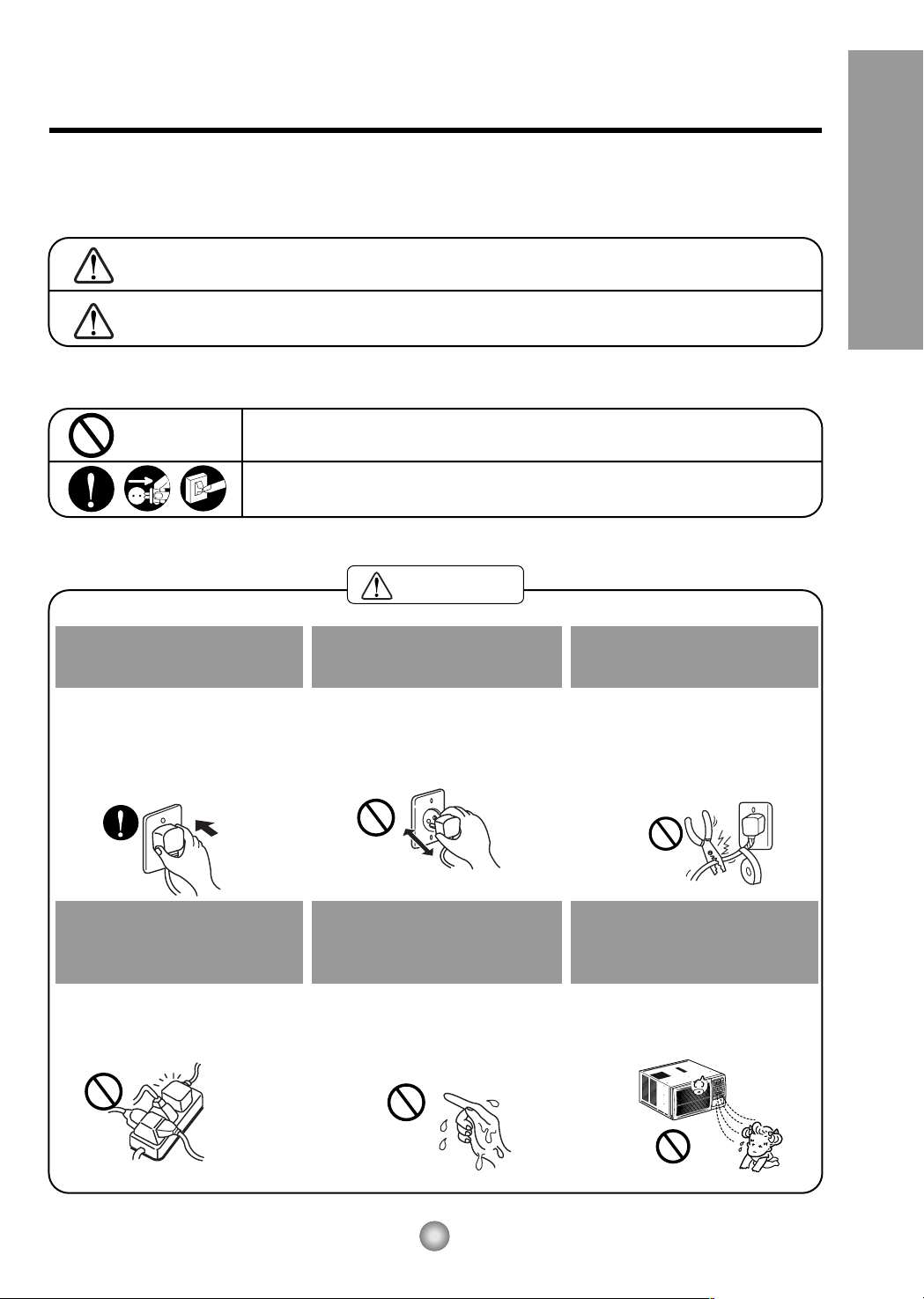
Precauciones Importantes de seguridad
ADVERTENCIA
39
Precauciones Importantes de Seguridad
Para prevenir tanto lesiones al usuario u otras personas como daños materiales, es preciso seguir estas instrucciones.
■ El manejo incorrecto debido a la inobservancia de estas instrucciones puede causar lesiones o daños cuya gravedad
está clasificada en las siguientes indicaciones.
ADVERTENCIA Este símbolo indica la posibilidad de lesiones mortales o graves.
PRECAUCION
Este símbolo indica la posibilidad de lesiones o daños
materiales.
■
El significado de los símbolos utilizados en este manual se indica a continuación.
Asegúrese de no hacerlo.
Asegúrese de seguir las instrucciones.
Conecte correctamente el
enchufle
• De otra forma, ello ocasionaría
una descarga eléctrica o
incendio a causa de la
generación de calor.
No opere o pare la unidad
insertando o tirando del
enchufe
• Ello ocasionaría una descarga
eléctrica o incendio a causa de la
generación de calor.
No dañe o utilize un cable
eléctrico inadecuado
• Ello ocasionaría una descarga
eléctrica o incendio.
No modifique el largo del cable
eléctrico, y tampoco comparta
el tomacorriente con otros
aparatos
• Ello ocasionaría una descarga
eléctrica o incendio a causa de la
generación de calor.
No lo maneje con las manos
humedas
• Puede ocasionar una descarga
eléctrica.
No exponga durante mucho
tiempo la piel al aire frío
procedente directamente del
acondicionador.
• Esto podría dañar su salud.
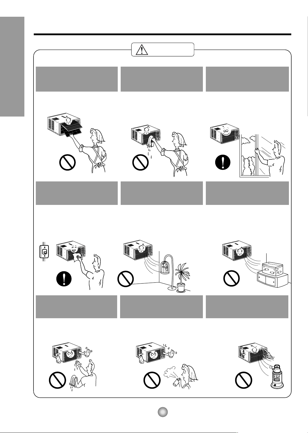
40
Precauciones Importantes de seguridad
PRECAUCION
Cuando se vaya a quitar el
filtro de aire no toque las
partes metálicas de la unidad
interior.
• Esto podría causar heridas.
No limpie el acondicionador
de aire con agua.
• El agua podría entrar en la
unidad y degradar el aislamiento.
También podría causar una
sacudida eléctrica.
Ventile bien cuando utilice el
acondicionador junto con
una estufa, etc.
• En este caso tal vez se produzca
una falta de oxígeno.
Cuando limpie la unidad,
desconecte la alimentación y
desconecte también el
disyuntor.
• Puesto que el ventilador gira a
alta velocidad durante la
operación, podría ocasionar
heridas.
NO ponga un animal doméstico
ni una planta donde quede
directamente expuesto al flujo
de aire.
• Esto podría dañar al animal o a
la planta.
No lo utilice para propósitos
especiales.
• No utilice este acondicionador de
aire para conservar dispositivos
de precisión, alimentos y objetos
de arte; no ponga tampoco
animales y plantas cerca de él.
Esto podría deteriorar la calidad,
etc.
No manipule los
interruptores con las manos
mojadas.
• Esto podría causar una sacudida
eléctrica.
No aplique aerosoles con
insecticida o productos
inflamables.
• Esto podría causar un incendio o
deformar la caja.
No ponga una estufa, etc.
donde quede expuesta al
flujo de aire directo.
•
Esto podría causar una
combustión imperfecta.
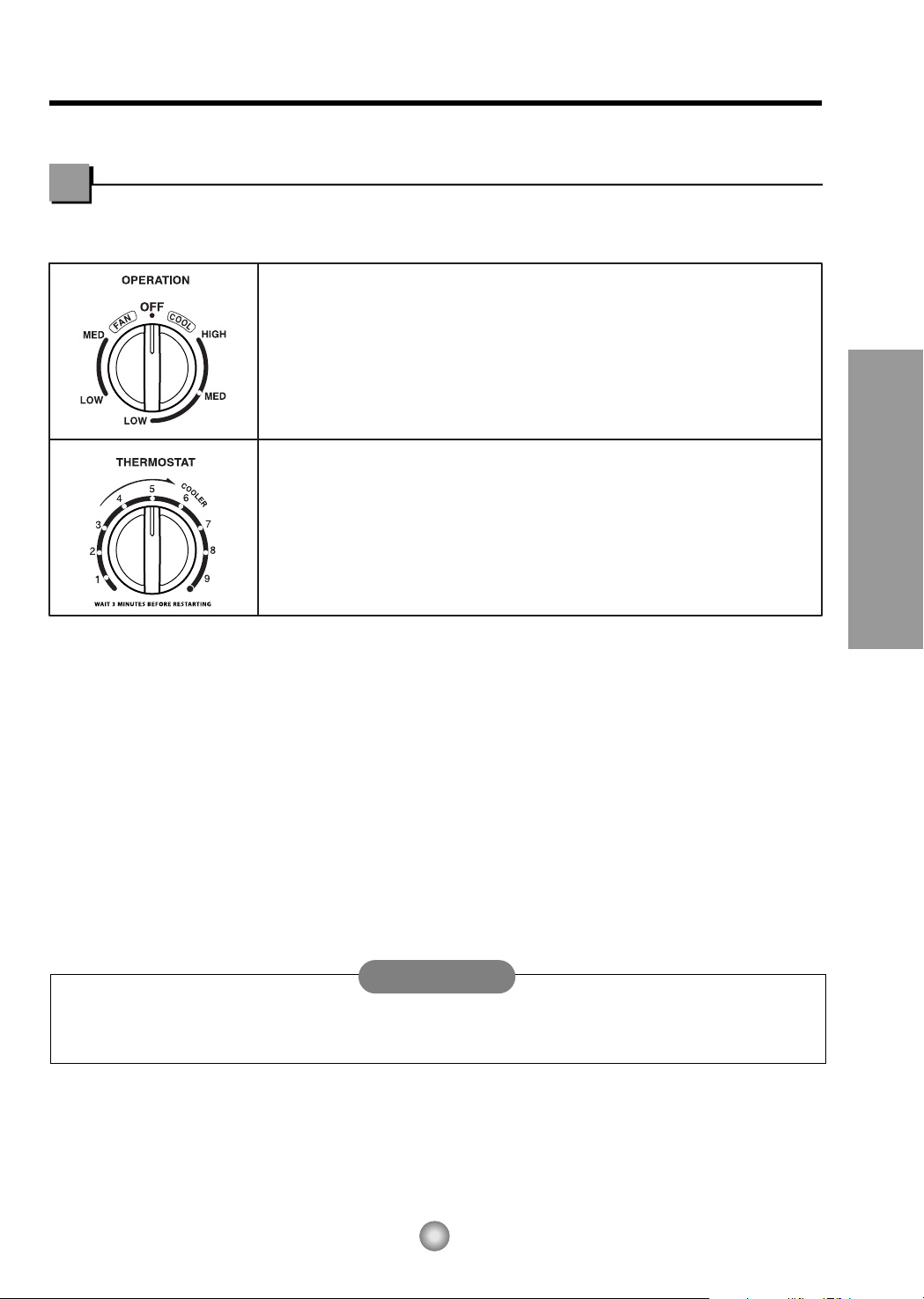
Instruccionnes de Funcionamiento
La apariencia de los controles será como uno de los siguientes.
Controles
41
Instrucciones de Funcionamiento
Cuando el aire acondicionado ha estado operando bajo la fase de enfriamiento y se apaga o se ajusta la
posicion de ventilacion, espere por lo menos 3 minutos, antes de reiniciar la operación de enfriamiento.
Off
(Apagado)
:
Apaga el aire acondicionado.
Med Fan(Ventilador Medio) :
Permite la operación de la velocidad media del ventilador sin enfriar.
Low Fan(Ventilador Bajo) :
Permite la operación de la velocidad baja del ventilador sin enfriar.
High Cool(Enfriamiento Alto) :P
ermite enfriar con la operación de la velocidad alta del ventilador.
Med Cool(Enfriamiento Medio) :
Permite enfriar con la operación de la velocidad media del ventilador.
Low Cool(Enfriamiento Bajo) :
Permite enfriar con la operación de la velocidad baja del ventilador.
La temperatura del aire interno será controlada
automáticamente. Mientras más alta sea la marca más frío
estará el aire internio. La temperatura se selecciona
posicionando el control en la marca deseada.
(i.e. el más alto el número, la más grande la refrigeración)
• PARA UN ENFRIAMIENTO NORMAL
1. Ponga el botón de Operation en la marca más grande, en High Cool.
2. Ajuste el control del Termostat en la marca deseada 5 (usualmente el punto medio es un buen punto para
comenzar). Si la temperatura del cuarto no es satifactoria después de un período de tiempo razonable,
ajuste el control de temperatura a una marca más grande (para una temperatura interna más fría) o a una
marca más pequeña (para que la temperatura interna sea menos fría).
• PARA UN ENFRIAMIENTO MAXIMO
1. Ponga el botón de Operation en la marca más grande.
2. Ponga el control del Termostat en la marca (9) más grande.
• PARA UNA OPERACIÓN SILENCIOSA
1. Ponga el botón de Operation en la marca más pequeña.
2. Ponga el Termostat en la temperatura interior deseada.
ADVERTENCIA
Modelo : CW-C84GU

Modelo
: CW-XC80HU
Modelo: CW-XC84HU
Modelos: CW-XC64HU, CW-XC84GU
Modelos: CW-XC64HK, CW-XC84HK
ECONOMY
FAN
COOL
DRY
hr
F
OPERATIONOPERATION
TEMPTEMP
TIMER MODE
OFF/ON
FAN
SPEED
FAN
SPEED
1
8
4
3 2 5
TIMER FANECONOMY
COOL
DRY
TIMERTIMER
MODEMODE
OFF/ON
FAN
SPEED
AIR
SWING
AIR
SWING
F
hr
4
1
7
8
3 2 5
4
1
3 6 2 5
8
OPERATION
TEMP
TIMER
AIR
SWING
AIR
SWING
FANECONOMY
COOL
DRY
TIMERTIMER
MODEMODE
OFF/ON
F
hr
FAN
SPEED
4
1
8
3 2 5
OPERATION
TEMP
42
Instrucciones de Funcionamiento
Controles
ENECNDIDO/APAGADO
• Para ENCENDER el sistema presione el
botón, y para APAGARLO presione el
botón otra vez.
• Este botón tiene prioridad sobre todos los
otros botones.
• Cuando Ud. Io enciende por primera vez,
el sistema está en el y la temperatura es
de 72˚F (22˚C).
FRÍO/VENTILADOR
• Cada vez que presione este botón, las
palabras COOL, FAN y DRY aparecerán
alternadamente.
(Modelos: CW-XC64HK, CW-XC84HK)
• Cada vez que presione este botón, las
palabras COOL, ECONOMY, FAN y DRY
aparecerán alternadamente.
(Modelos: CW-XC64HU, CW-XC84HU,
CW-XC84GU)
MARCADOR DE ENCENDIDO/APAGADO
• Cada vez que presione este botón, el
marcador de tiempo se ajustará de la
siguiente manera: (1Hora → 2 Horas →
3 Horas → 4 Horas → 5 Horas → 6 Horas
→ 7 Horas → 8 Horas → 9 Horas →
10 Horas → 11 Horas → 12 Horas →
Cancelar).
• La temperatura de ajuste se elevará
2˚F(1˚C), 30 minutos después, y otros
2˚F(1˚C)media hora después.
VELOCIDAD DEL VENTILADOR
• Cada vez que presione este botón, el
ajuste es como sigue {Alto(F3) → Bajo(F1)
→ Alto(F2) → Alto(F3)...}
AJUSTE DE LA TEMPERATURA
• Este botón puede controlar la temperatura del
cuarto automáticamente. La temperatura se
puede ajustar de grado en grado, desde 60˚F
hasta 86˚F cada 1˚F (16˚C hasta 30˚C cada
1˚C). Seleccione el número más bajo para la
temperatura más baja en el cuarto.
AHORRADOR DE ENERGÍA
El ventilador se detiene cuando el compressor no
sigue enfriando.
• Aproximadamente cada 3 minutos el ventilador
se encenderá, y necesitará verificar la
temperatura del cuarto para saber si es
necesario más enfriamiento.
AUTOGIRO
Este botón puede controlar automáticament la
dirección del flujo de aire.
RECEPTOR DE SEÑAL
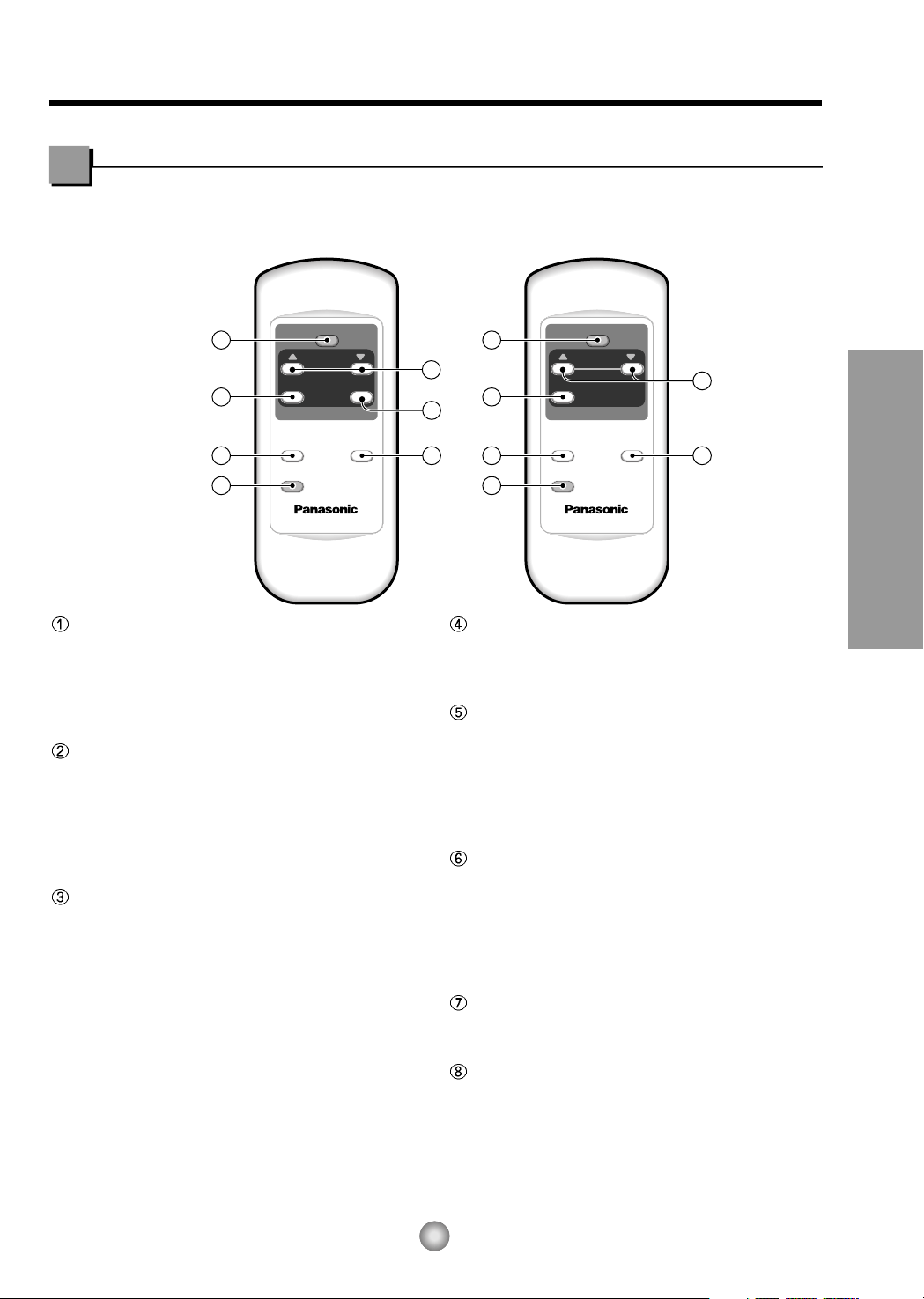
OPERATION
TEMP
TIMER
MODE
ECONOMY
FAN SPEED
1
3
2 4
6
5
Modelo: CW-XC84HU
Modelos: CW-XC64HU, CW-XC64HK
CW-XC84GU, CW-XC84HK
OPERATION
TEMP
TIMER
AIR
SWING
MODE
ECONOMY
FAN SPEED
1
3
2 4
6
5
7
43
Instrucciones de Funcionamiento
ENECNDIDO/APAGADO
• Para ENCENDER el sistema presione el botón, y para
APAGARLO presione el botón otra vez.
• Este botón tiene prioridad sobre todos los otros botones.
• Cuando Ud. Io enciende por primera vez, el sistema está
en el y la temperatura es de 72˚F(22˚C).
FRÍO/VENTILADOR
• Cada vez que presione este botón, las palabras COOL,
FAN y DRY aparecerán alternadamente. Modelos:
CW-XC64HK,CW-XC84HK)
• Cada vez que presione este boton, las palabras COOL,
ECONOMY,FAN y DRY aparecerán alternadamente.
(Modelos: CW-XC64HU, CW-XC84HU, CW-XC84GU)
MARCADOR DE ENCENDIDO/APAGADO
- OPERACIÓN DE PARADA:
• Cada vez que presione este botón, cuando el sistema
esté operando, el marcador de tiempo se ajustará de la
siguiente manera: (1Hora → 2 Horas → 3 Horas →
4 Horas → 5 Horas → 6 Horas → 7 Horas → 8 Horas →
9 Horas → 10 Horas → 11 Horas → 12 Horas → 0).
• La temperatura de ajuste se elevará 2˚F(1˚C),
30 minutos después, y otros 2˚F(1˚C) media hora
después.
- OPERACIÓN DE INICIACIÓN:
• Cada vez que presione este botón, cuando el sistema
esté operando, el marcador de tiempo se ajustará de la
siguiente manera: (1Hora → 2 Horas → 3 Horas →
4 Horas → 5 Horas → 6 Horas → 7 Horas → 8 Horas →
9 Horas → 10 Horas → 11 Horas → 12 Horas → 0).
VELOCIDAD DEL VENTILADOR
• Cada vez que presione este botón, el ajuste es
como sigue. {Alto(F3) → Bajo(F1) → Alto(F2) →
Alto(F3)...}
AJUSTE DE LA TEMPERATURA
• Este botón puede controlar la temperatura del
cuarto automáticamente. La temperatura se puede
ajustar de grado en grado, desde 60˚F hasta 86˚F
cada 1˚F (16˚C hasta 30˚C cada 1˚C). Seleccione
el número más bajo para la temperatura más baja
en el cuarto.
AHORRADOR DE ENERGÍA
El ventilador se detiene cuando el compressor no
sigue enfriando.
• Aproximadamente cada 3 minutos el ventilador se
encenderá, y necesitará verificar la temperatura
del cuarto para saber si es necesario más
enfriamiento.
AUTOGIRO
Este botón puede controlar automáticament la
dirección del flujo de aire.
DRY
Cuando esta unidad se torna al modo seco, el
ventilador gira en velocidad lenta. El ventilador se
detiene cuando el compresor se para de enfriar.
Aproximadamente cada 3 minutos se encendera el
ventilador y la unidad comprueba la temperatura del
aire de la habitacion para ajustarse a si mismo.
Precaución:
El dispositivo de control remoto no funcionará adecuadamente si la ventana sensora del acondicionador de aire es
expuesta a luz fuerte, o si hay obstáculos entre el dispositivo de control remoto y el acondicionador de aire.
Control remoto
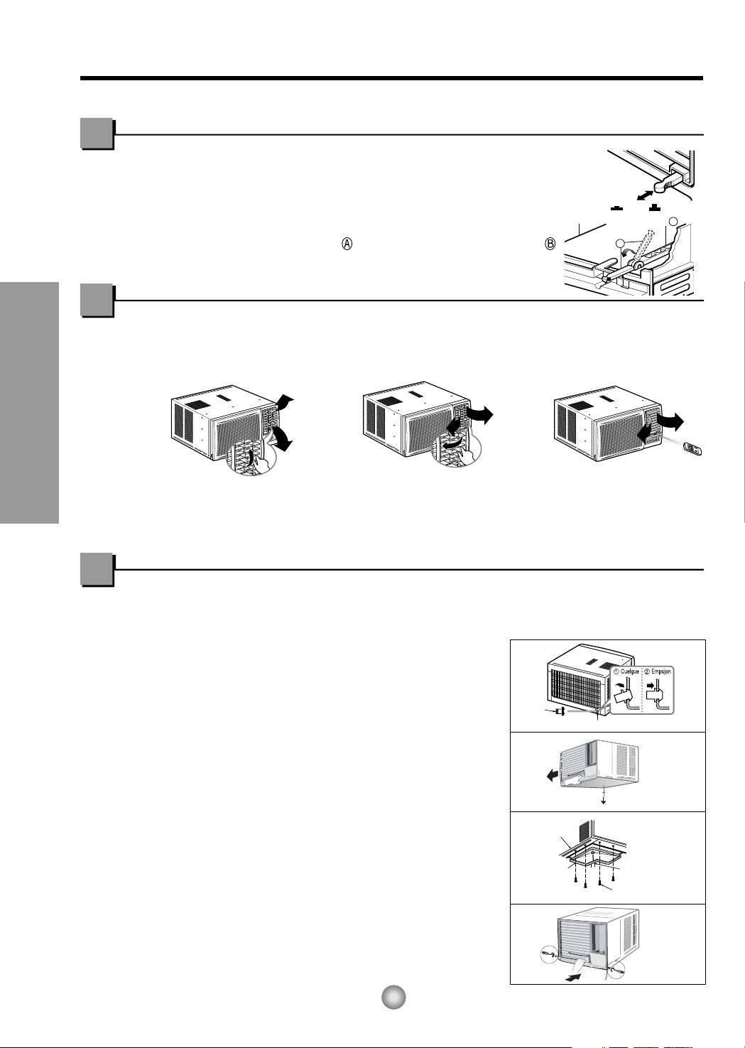
Instrucciones de Funcionamiento
Parte
A
Parte
B
O
F
F
/
O
N
O
P
E
R
A
T
I
O
N
T
E
M
P
/
T
I
M
E
R
C
O
O
L
F
A
N
H
I
G
H
M
E
D
L
O
W
M
O
D
E
F
A
N
S
P
E
E
D
S
E
T
T
I
M
E
R
S
E
T
/
C
A
N
C
E
L
A
I
R
S
W
I
N
G
E
C
O
N
O
M
Y
h
r
F
W
i
r
e
l
e
s
s
R
e
m
o
t
e
C
o
n
t
r
o
l
Retire el tapón
de goma
Controlado
por manual
Controlado
por manual
Controlado por
Director Remoto
(Modelo:CW-XC84HU)
VENTCERRADO
ABIERTO
Tapa
del desagüe
Tubo
BANDEJA
DE DRENAJE
MANGUERA DE DRENAJE
El diámetro
interior 17mm (5/8")
TA PA
TORNILLOS
Fig. 4
Fig. 3
Fig. 2
Fig. 1
O
F
F/
O
N
O
P
E
R
A
T
I
O
N
T
E
P
/
T
I
C
O
O
L
F
A
N
H
I
G
H
M
E
D
L
O
W
M
O
E
F
A
N
S
P
E
E
D
S
E
T
T
I
M
E
R
S
E
T
/
C
N
E
A
I
R
E
C
O
N
O
M
Y
F
W
i
r
e
le
s
s
R
e
m
o
t
e
C
o
n
t
r
o
l
44
Controles adicionales e informacion importante.
Ventilación
La palanca de ventilación debe estar en posición CERRADA para poder mantener las
mejores condiciones de enfriamiento. Cuando se necesite aire fresco en la habitación,
coloque la palanca de ventilación en posición ABIERTA. La Compuerta es abierta y el
aire de la habitación es expulsado.
NOTA:
Antes de utilizar la característica de ventilación, haga un kit de ventilación.
Primero, hale hacia abajo la parte hasta que quede horizontal con la parte .
Como controlar la direccion del aire
La dirección del aire puede ser controlada cuando usted desee enfriar, ajustando la
palanca vertical y la palanca horiziontal.
• CONTROL DE LA DIRECCIÓN VERTICAL DEL AIRE
La dirección vertical del aire es
ajustada rotando la palanca horizontal
hacia adelanto o hacia atrás.
La dirección horizontal del aire es ajustada
rotando la palanca vertical hacia la derecha o
hacia la izquierda manualmente o por Director
Remoto.
• CONTROL DE LA DIRECCIÓN HORIZONTAL DEL AIRE
Como Installar el Tubo de Desagüe
En climas húmedos, es posible que la BANDEJA EVAPORADORA se llene de agua.
Para quitar el agua acumulado, es preciso conectar el tubo de desagüe.
Quite la TAPA DEL DESAGÜE y conecte el TUBO a la BANDEJA EVAPORADORA.(Ver Fig.1)
Opcional(CW3H02502C)
1. Retire el tapón de plástico y deslice el chasis fuera
del armario.
(Ver Fig.2)
2. Instale la bandeja de drenaje por encima de la
esquina de la tapa de donde retiró el tapón con 4 (o
2) tornillos.
(Ver Fig.3)
3. Conecte la manguera de drenaje a la salida situada
en la parte inferior de la bandeja de drenaje. Puede
adquirir una manguera de drenaje o una tubería
apropiada en su localidad que satisfaga sus
necesidades particulares (la manguera no se
suministra).
(Ver Fig.3)
4. Seleccione la conexión más apropiada entre las
figuras siguientes (teniendo en cuenta el orificio de la
unidad) para acoplar la bandeja de drenaje en su
unidad.
(Ver Fig.3)
5. Deslice el chasis en el interior del armario.
Vuelva a apretar los tornillos del armario. Fije el
armario al chasis con tornillos.
(Ver Fig.4)
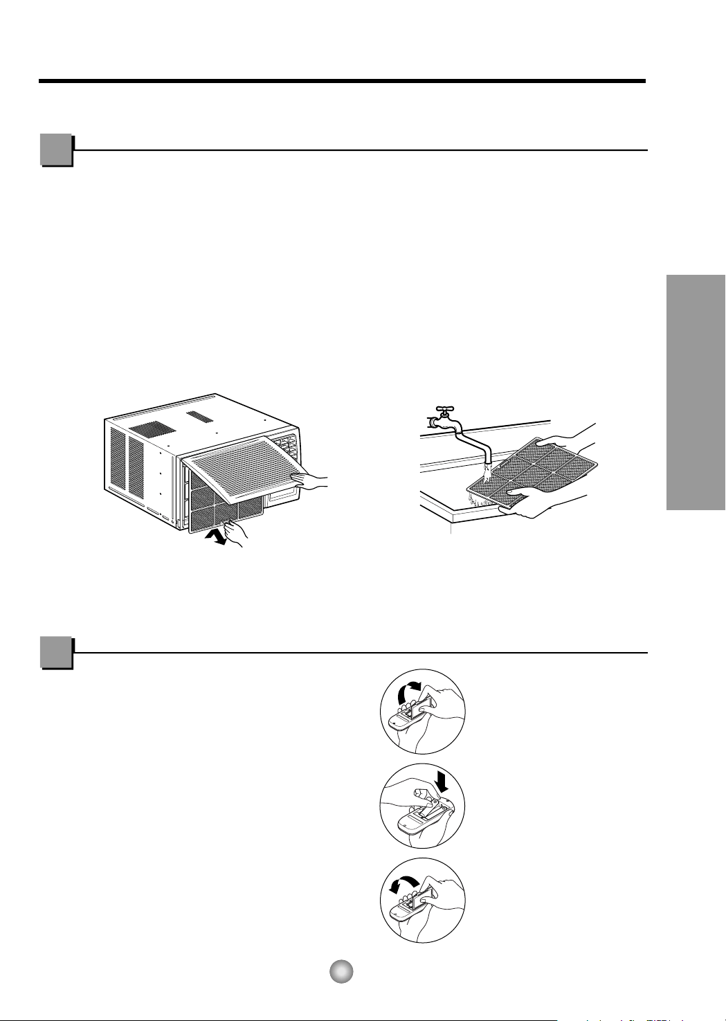
Instrucciones de Funcionamiento
45
Limpieza de filtro de Aire
El filtro de aire detrás de la rejilla frontal debe ser revisado y limpiado por lo menos una
vez por cada dos semanas o más frecuentemente si es necesario.
La rejilla es diseñado para limpiar el filtro tanto hacia arriba como hacia abajo.
PARA REMOVER:
1. Abra la rejilla hacia arriba tirando la parte inferior de la rejilla o hacia abajo tirando la
parte superior de la rejilla.
2. Usando una lengüeta, tire el filtro ligeramente hacia arriba para sacarlo por abajo o
arriba.
3. Limpie el filtro con agua tibia y jabonosa bajo 40°C (104°F).
4. Enjuague y sacuda el filtro suavemente bajo la corriente de agua y déjelo secar antes
de reponerlo.
PRECAUCION: NO OPERE el aire acondicionado sin filtro ya que la suciedad y el tamo
obstruirá el filtro y reducirá la eficiencia del funcionamiento.
Cuidado y Mantenimiento
APAGUE EL AIRE ACONDICIONADO Y SAQUE EL ENCHUFE DEL TOMA CORRIENTE DE LA PARED
.
Cómo poner las baterías
1. Quite la tapa de la parte posterior del telemando.
Para ello haga deslizar la tapa según la dirección
del la flecha.
2. Introduzca las dos AAA célula seca baterías,
asegurándose de que las direcciones (+) y (-)
estén colocadas correctament. Use baterías
nuevas.
3. Volver a cerrar, resbalando la tapa hasta la
posición inicial.
• No utilice baterís
recargables, éstas son
diferentes de forma, de
dimensión y uso respecto a
las baterías secas usuales.
• Seque las baterías del
telemando cuando el
acondicionador no vaya a
ser usado durante un largo
período.

46
Características e Instalacion
Aprender el nombre de las partes antes de la instalación le ayudará a entender el proceso
de instalación.
Características
Características
F
A
N
E
C
O
N
O
M
YC
O
O
L
D
R
Y
T
I
M
E
R
T
I
M
E
R
T
I
M
E
R
M
O
D
E
M
O
D
E
O
F
F
/
O
N
F
h
r
F
A
N
S
P
E
E
D
A
I
R
S
W
I
N
G
A
I
R
S
W
I
N
G
RECOLECTOR DE AIRE
(BANDEJA DE ENTRADA)
SALIDA DE AIRE
DEFLECTOR HORIZONTAL DE AIRE
(VENTANILLAS VERTICALES)
VENTANILLAS VERTICALES
DEFLECTOR DE AIRE HORIZONTAL
(VENTANILLAS HORIZONTALES)
CABLE DE CONEXIÓN ELÉCTRICA
BANDEJA
CONDENSADOR
COMPRESOR
SUSPENSORES
CABLE DE CONEXIÓN ELÉCTRICA
BANDEJA
CONDENSADOR
COMPRESOR
SUSPENSORES
CABLE DE CONEXIÓN ELÉCTRICA
BANDEJA
CONDENSADOR
COMPRESOR
SUSPENSORES
Modelos: CW-XC64HU
Modelo: CW-C84GU
Modelos: CW-XC64HK
CW-XC84HK
CW-XC64HU
CW-XC84GU
GABINETE
REJILLA FRONTAL
FILTRO DE AIRE
EVAPORADOR
PANEL DE CONTROL
EVAPORADOR
PANEL DE CONTROL
EVAPORADOR
PANEL DE CONTROL
CONTROL REMOTO
CONTROL REMOTO
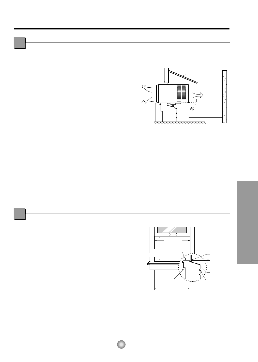
;
;
Aproximamente
1
/
2
"
30"~60"
Pabellón
Aire frio
Cerca
Over 20"
Radiacion
de calor
Interior pared
Taburete
22" a 36"
1
/2
" a 11
/4
"
Retallo
Aiféizar
Exterior
18
1
/2" min
(Sin cubierta de armazon)
15" min
(Con cubierta de armazon)
47
Instrucciones de Instalación
Características e Instalacion
Elija el major lugar
1. Para prevenir la vibración y el ruido,
asegure de que la unidad esté instaalada
segura y firmemente.
2. Instale la unidad donde el sol no refleje
directamente en la unidad.
3. La salida debe extenderse hacia afuera por
lo menos 11" y no debe haber obstáculos,
como cercas o paredes, en 20" de la parte
de atrás del gabinete porque va ha prevenir
la rediación de calor del condensador.
Restriciones del aire de afuera reducirá
grandemente la eficiencia del aire
acondicionado.
CUIDADO: Todas las ventanillas de los lados
del gabinete deben mantenerse
expuestas hacia afuera de la
estructura.
4. Instale la unidad un poco inclinada de tal forma que la parte trasera esté ligeramente
más baja que el frente(cerca de
1
/
2").
Esto forzará el agua del condensador hacia afuera.
5. Instale la unidad con la parte inferior cerca de 30"~60" arriba nivel de suelo.
Requistios de ventana
Esta unidad está diseñada para que sea
instalada en ventanas dobles estándares con
una abertura actual de ancho desde 22" a
36".
La parte superior e inferiro de la ventana
debe abrir lo suficiente para permitir una
abertura vertical libre de 15" desde la parte
inferior de la ventana hasta la base de la
misma.
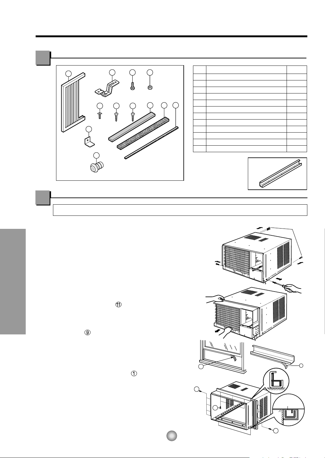
Características e Instalacion
9
5
5
5
(Tipo A)
(Tipo A)
11
Tornillos para
transporte
Guía mas baja
1
2 3 4
8 11
12
9
765
10
PREPARACION DEL CHASIS
1. Remueva los tornillos cuales sujetan el
gabinete a ambos lados y en la parte de atrás.
2. Deslice la unidad fuera del gabinete tomando
el agarradero de la bandeja y hale hacia el
frente mientras mantiene el gabinete.
3. Corte el marco de la ventana con el largo
apropiado. Desprenda la parte de atrás y
sujete el FOAM-PE en la parte inferior del
marco de la ventana.
4. Remueva el empaque desde el sello de la guia
superior y péguelo al fondo de la guia
superior.
5. Sujete la guía superior en la parte de arriba
del gabinete con 3 tornillos tipo A.
6. Inserte los paneles guías en la guía
superior en la guia maro.
7. Sujete el armazon a la unidad con 4 tornillos.
(Tipo A)
48
Contenido del Juego de Instalación
Requisitos de las herra mientas sugeridas
DESARMADOR (+, -), REGLA, CUCHILLO, MARTILO, LAPIZ, NIVEL
NO. NOMBRE LA PARTE
CANTIDAD
1 PANEL GUÍA2
2 SOPORTE DE ALFÉIZAR 2
3 TORNILLO 2
4 TUERCA 2
5 TORNILLO(TIPO A) 10mm (25/64") 16
6 TORNILLO(TIPO B) 3
7 TORNILLO(TIPO C) 5
8 TIRA DE GOMA 1
9
BANDA ADHESIVA (466mm x 10mm x 2mm)
1
10
CHAPA DE SOPORTE PARALA VENTANA
1
11
BANDA ADHESIVA (920mm x 30mm x 2mm)
1
12 TAPA DEL DESAGÜE1
D5.1mm (3/16")/16mm (5/8")
D4.1mm (5/32")/16mm (5/8")
■ La barra de retención
superior está en el
empaque del producto
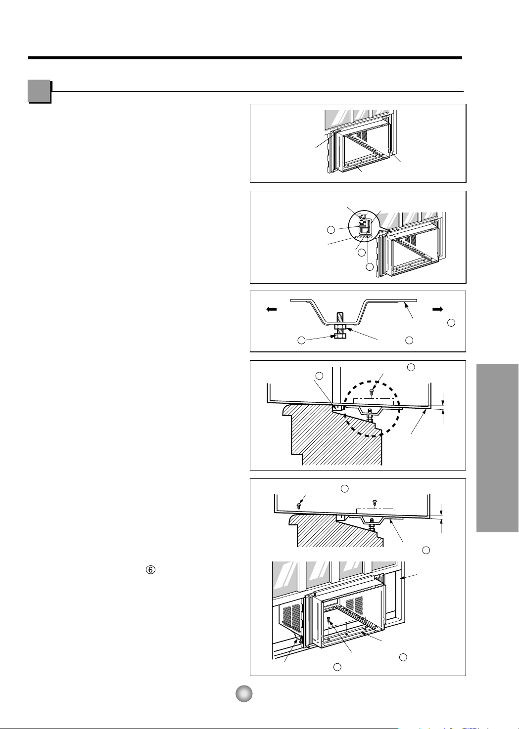
49
Características e Instalacion
Aproximamente 1/2"
Soporte del Alféizar
2
Pista de
Marco
Angulo de Delante
Tornillo(Tipo B)
6
Soporte del Alféizar
2
Tornillo(Tipo B)
6
Interior
Exterior
Gabinete
Aproximamente 1/2"
Guia Marco
9
Tornillo(Tipo A)
5
Interior Exterior
Soporte del Alféizar
2
Tuerca
4
Tornillo
3
Guía Superior
Marco de Ventana
Taburete de la Ventana
Angulo de Delante
Guía Superior
Panel Guía
1
Banda adhesiva
9
Banda adhesiva
11
Gabinet
1. Abra la ventana. Marque una línea en el
centro del banqueta de la ventana(o la
ubicación deseada del aire acondicionado).
Cuidadosamente ubique el gabinete en la
banqueta de la ventana y alinee la marca
central en el frente inferior con el centro de la
línea marcada en la banqueta de la ventana.
(Ver Fig.1)
2. Hale hacia abajo la parte inferior de la
ventana hasta que se una detrás de la guía
superior.(Ver Fig.2)
NOTA:
• No hale la ventana hacia abajo tan
apretadamente que el movimiento del panel
guía sea restringido.
3. Ligeramente ensamble el soporte del alfeizar
usando las partes de la fig. 3.
4. Seleccione la posición que ubicará el soporte
del alféizar cerca del punto más exterior del
alféizar.(Ver Fig. 4)
5. Pegue el soporte antepecho a los rieles de la
caja en relacion a la posicion deseada
usando dos tornillos Tipo A en cada soporte.
(Ver Fig. 4)
6. El gabinete debe ser instalado con una
pequeña caída(cerca de
1
/2") hacia abajo
hacia afuera (Ver Fig. 5).
7. Adjunte el gabinete al banquete de la ventana
atornillando los tornillos
(Tipo B: Largo
dieciséis milímetros y menos.) a través del
ángulo frontal en la banqueta de la ventana.
8. Hale cada panel guía completamente a cada
lado de la ventana y repita del paso 2.
Instalación del Gabinete
Fig. 1
Fig. 2
Fig. 3
Fig. 4
Fig. 5
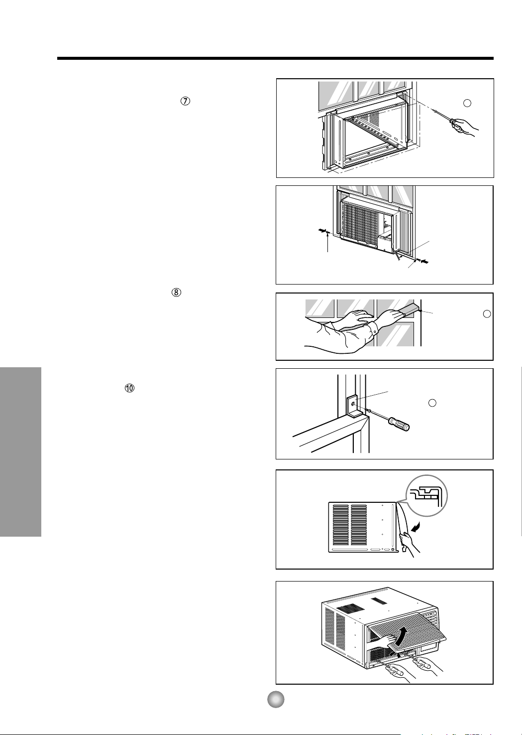
Tornillo
Tornillo
Conrdon
de Alimentacion
7
Chapa de soporte para
la ventana
10
Tira de Goma
8
Tipo C
50
Características e Instalacion
9. Adjunte cada panel guía a cada lado de la
ventana usando tornillos (Tipo C).
(Ver Fig. 6)
PRECAUCION: No perfore la charola del fondo. La
unidad está diseñada para operar
con aproximadamente 1/2" de agua
en la charola del fondo.
10. Deslice el chasís dentro del gabinete.
(Ver Fig. 7)
CUIDADO: Por razones de seguridad, re
instale los tornillos en los lados del
gabinete.
11. Corte la tira de goma a la medida
apropiada e introdúzcala entre la parte
superior e inferior de la ventana.
(Ver Fig. 8)
12. Sujete la chapade soporte en el marco de
la ventana con untornillo tipo C.
(Ver Fig. 9)
13. Pegue el panel frontal a la caja insertando
los fijadores en el panel adentro los del
panel de la caja. (Ver Fig. 10)
NOTA: Se refiere por favor p.40 para poner
juego de ventilación.
14. Levante la parrilla de entrada y ajústela
con tornillos Tipo A, através de la parrilla
frontal. (Ver Fig. 11)
15. Ahora la instalación del aire acondicionado
en la ventana es completada. Vea los DATOS
ELECTRICOS para instalar el cable de
alimentación en la toma de corriente.
Fig. 6
Fig. 7
Fig. 8
Fig. 9
Fig. 10
Fig. 11

No lo corte bajo
ninguna circunstancia
o remueva la punta
del enchufe.
Corc n El ctrico Utilice el enchufe de la pared Consumo de Energ a
Cord n el ctrico con
puntas para enchufar
Standard 125V, enchufe de 3
L neas de 15A, 125V AC
Utilice un fusible de
15AMP o un
Interruptor
51
Características e Instalacion
USO DE CORDONES DE EXTENSION
Debido al potencial de peligro a su seguridad bajo ciertas circunstancias recomendamos encaredidamente no utiliar cordones de
extensión. Sin embargo, si usted decide usar un cordón de extensión, es absolutamente necesario que este sea un cordón
listado bajo UL de tres espigas con conexión a tierra calificado 15A, 125V.
Datos Electricos
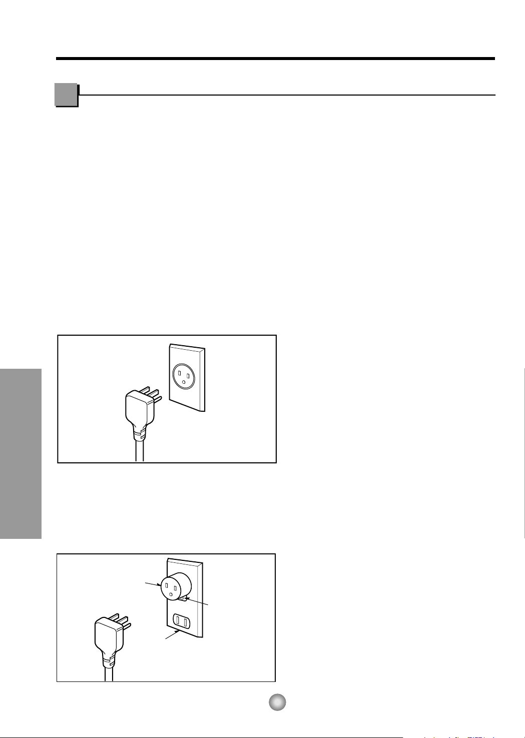
MÉTODO PREFERIDO
ASEGÚRESE QUE EXISTE
DEBIDA NEUTRALIZACIÓN ANTES
DE UTILIZAR EL APARATO.
MÉTODO TEMPORAL
Adaptador
Cubierta del interruptor
Tornillo de metal
52
Informacion Electrica (Aplica a USA y Puerto Rico)
Características e Instalacion
IMPORTANTE
(FAVORLEA CON ATENCIÓN)
POR LA SEGURIDAD PERSONAL DEL
USUARIO, ESTE APARATO DEBE SER
DEBÍDAMENTE NEUTRALIZADO.
El cordón de energía de éste aparato esta
equipado con tres patas(cable a tierra). Utilice
éste con un enchufe de pared de tres salidas(a
tierra)(Fig. 12) para minimizar el peligro de
choque eléctrico. El cliente debe revisar el
receptor de pared y el circuito por un
electricista calificado para asegurarse que la
recepción esta debidamente neutralizada.
NO CORTE O REMUEVA LA TERCERA
PATA(GROUND) DEL ENCHUFE.
A. SITUACIONES EN LAS CUALES EL
APARATO ES DESCONECTADO
OCASIONALMENTE:
Debido al peligro potencial, nosotros no
recomendamos el uso de adaptadores. Sin
embargo, si usted desea utilizar un adaptador,
una CONEXIÓN TEMPORAL, puede ser
efectuada. Utilice adaptadores UL, disponibles
en la mayoría de los estable cimientos de
herramientas(Fig. 13). La pata mas grande del
adaptador debe ser alineada con la pata mas
grande del interruptor para asegurarse una
polarización adecuada.
CUIDADO: Adaptar la terminal del ground del
adaptador a la cubierta de la pared con un
tornillo no neutraliza el aparato a menos que la
cubierta del tornillo sea de metal, u no sea
insolada, y el receptor de pared este
neutralizado a través del alambrado del la
casa. El cliente debe hacer verificar el circuito
por un electricista calificado para asegurarse
que el receptor esta debidamente neutralizado.
Desconecte el cordón de energía del
adaptador, utilizado una mano en cada uno.
De lo contrario, la terminal del adaptador
puede romperse. NO UTILICE el aparato con
un enchufe roto.
B. SITUACIONES EN LAS CUALES EL
APARATO ES DESCONECTADO CON
FRECUENCIA.
No utilice un adaptador en estas
circunstancias. Desconectar el cordón de
energía con frecuencia lo llevará al eventual
rompimiento de la terminal de neutralización.
La saluda de energía de la pared debe ser
reemplazada por una salida de tres
patas(neutralizada).
USO DE EXTENSIONES
Debido al peligro potencial, no recomendamos
la utilización de extensiones. Sin embargo, si
usted desea utilizar una extensión, utilice una
certificada por CSA/UL de tres alambres,
catalogada 15A, 125V.
Fig. 12
Fig. 13
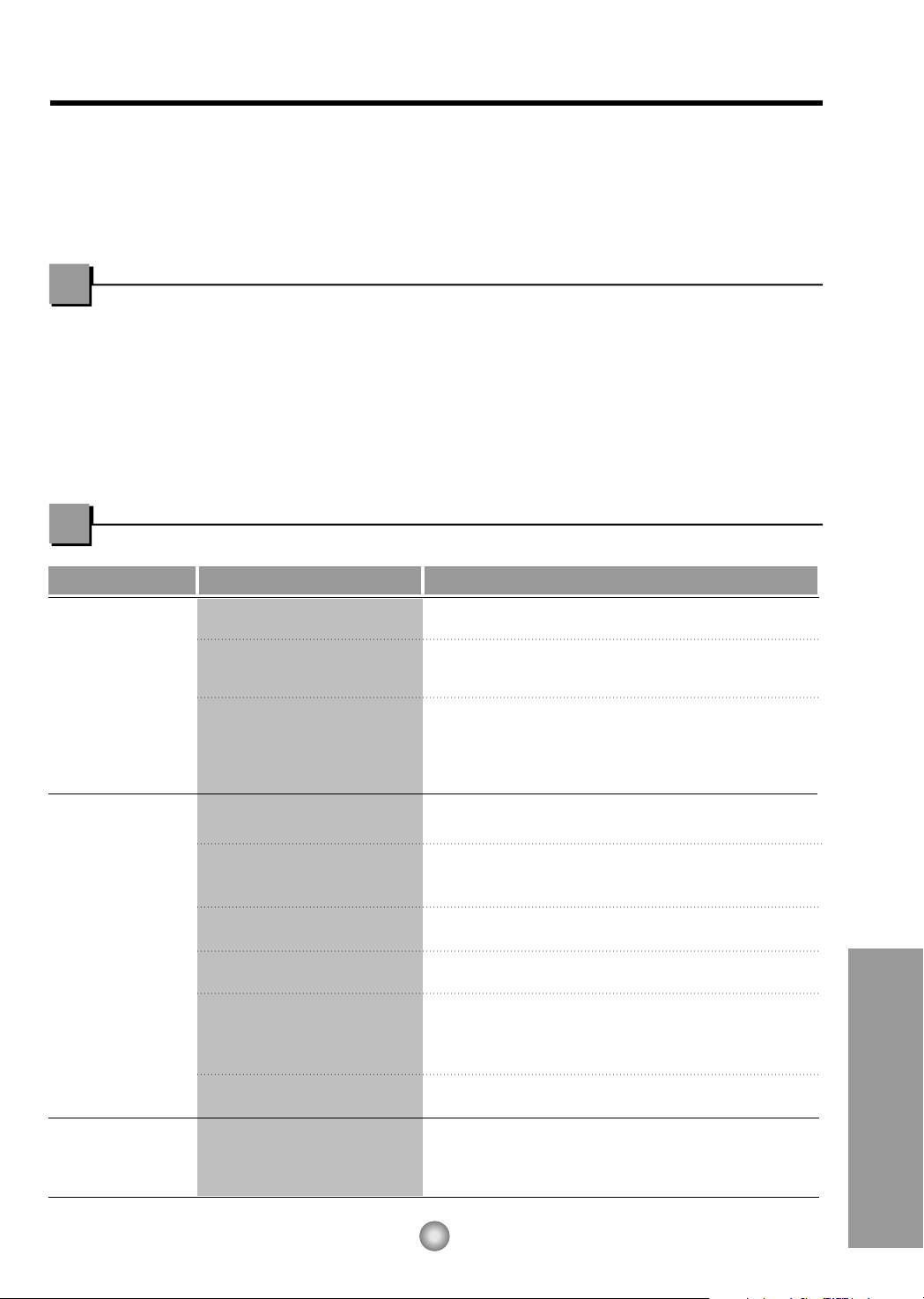
Before you call for service...
53
Antes de avisar al Servicio Técnico
Antes de avisar al Servicio Técnico
Tips para solucionar problemas
(Ahorre temopo y dinero) Cuando tenga algún problema primero consulte el cuadro que se
encuentra abajo y tal vez no necesite llamar para solicitar servicio técnico.
Operación normal
• Durar te dias lluviosos o cuando la humedad es alta usted puede escuchar un ruido metállco causa
do por agua recogida y arrojada contra el condensador. Esta caracteristica ayuda a remover la
humedad y mejorar la eficiencia.
• Usted puede escuchar que el relevo hace un click cuando se enciende o apaga el ciclo del comp
esor.
• Durar te dias lluviosos o cuando la humedad es alta el agua será recolectada on la base del
aparato. Esta agua podrá fluir y será eliminada por el lado externo de la unidad.
• El ventilador podrá correr aún cuando el compresor no esté encendido.
Operación anormal
Probama Causas posibles Que hacer
■ El aire acondicionado está
desconectado.
■ El fusible está quemado/el
interruptor de energía se ha
bloqueado.
■ Falta de energía.
■ El flujo de aire esta
restringido.
■ Coloque el control de
TEMPERATURA en un
número más alto.
■ El filtro de aire está sucio.
■ El cuarto aún está caliente.
■ El aire frio se está
escapando.
■
El serpentin de refrigeración
se ha
congelado.
■ El hielo bloquea el flujo de
aire y detiene el
enfriamiento del cuarto.
• Asegúrese que ei aire acondicionado está conectado
completamente a la fuente de energia.
• Cheque los fusibles/interruptor de la casa y reemplace
los fusibles o reestablezca el interruptor de energía.
• Cuando la energía se reestablezca, espere 3 minutos
para encender de nuevo el aire acondicionado. Con esto
evitará que se produzca una sobrecarga en el compresor.
• Asegúrese que no haya cortinas, persianas o muebles
bloqueando el frente del aire acondicionado.
• Gire el control de TEMPERATURA a un número más
bajo.
• Limpie el filtro por lo menos cada dos semanas. Vea la
sección de instrucciones de operación.
• Cuando usted enciende el aire acondicionado debe
esperar un momento para que la habitación se enfrie.
• Asegúrese que todas las salidas de aire estén cerradas
para que el aire regrese.
• Coloque la ventana del aire acondicionado en la
posición más cercana.
• Establezca una temperatura más alta.
•
Ajustar el control de mode en 'Ventilación Alta' o
'Erfriamiento Alto' con la temperatura alta.
El aire
acondicionado no
enciende
El aire
acondicionado no
enfría corno
debiera
El aire
acondicionado
enfria dernasiado
Modelos: CW-XC64HU, CW-XC64HK, CW-XC84GU, CW-XC84HK, CW-XC84HU
54
Operación anormal
Modelo: CW-C84GU
Probama Causas posibles Que hacer
■ El aire acondicionado está
desconectado.
■ El fusible está quemado/el
interruptor de energía se ha
bloqueado.
■ Falta de energía.
■ El flujo de aire esta
restringido.
■ Se ha elegido una
temperatura mas caliente
de lo deseada.
■ El filtro de aire está sucio.
■ El cuarto aún está caliente.
.
■ El aire frio se está
escapando.
■
El serpentin de refrigeración
se ha
congelado.
■ El hielo bloquea el flujo de
aire y detiene el
enfriamiento del cuarto.
• Asegúrese que ei aire acondicionado está conectado
completamente a la fuente de energia.
• Cheque los fusibles/interruptor de la casa y reemplace
los fusibles o reestablezca el interruptor de energía.
• Si hay una falta en el suministro de energía apague su
aparato(Off). Cuando la energía se reestablezca,
espere 3 minutos para encender de nuevo el aire
acondicionado. Con esto evitará que se produzca una
sobrecarga en el compresor.
• Asegúrese que no haya cortinas, persianas o muebles
bloqueando el frente del aire acondicionado.
• Elija una temperatura mas fria. Entre mâs baja sea la
temperatura elegida mas fria sera la zona
acondicionada.
• Limpie el filtro por lo menos cada dos semanas. Vea
la sección de instrucciones de operación.
• Cuando usted enciende el aire acondicionado debe
esperar un momento para que la habitación se enfrie.
• Asegúrese que todas las salidas de aire estén
cerradas para que el aire regrese.
• Establezca una temperatura más alta.
•
Elija el modo alto del ventilador Med Fan o enfriado
alto High Cool con el termostato en el número 1 o 2.
El aire
acondicionado no
enciende
El aire
acondicionado no
enfría corno
debiera
El aire
acondicionado
enfria dernasiado
55
MEMO
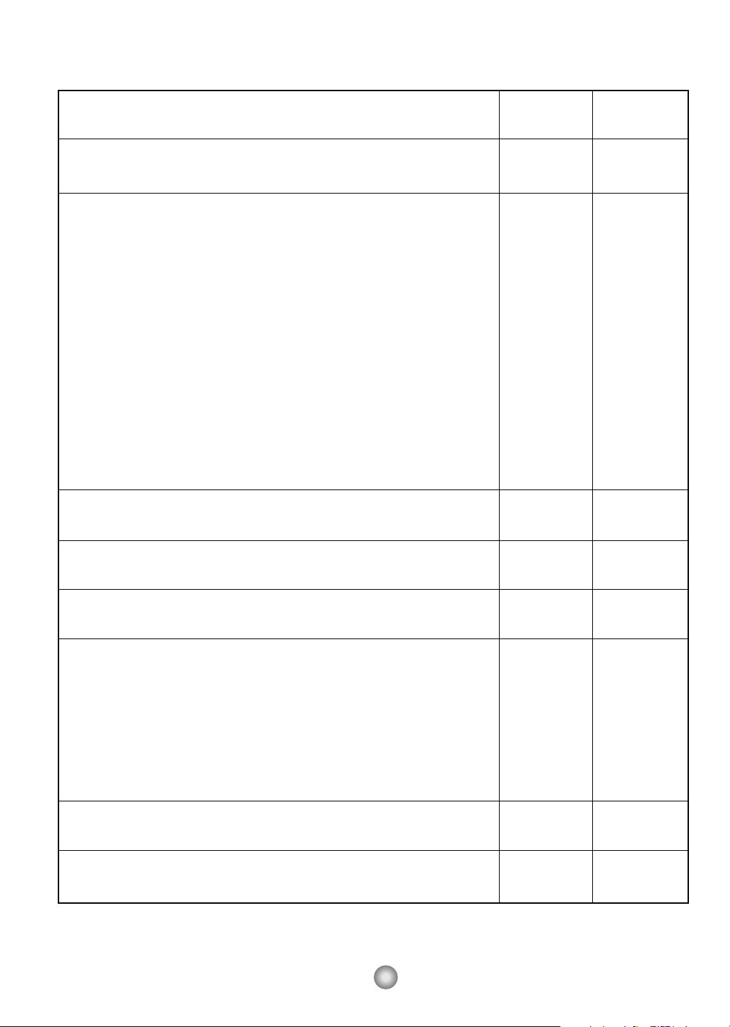
56
Model
Modèle
Modelo
COOLING CAPACITY Btu/h 6,000 7,800
CAPACITÉ DE REFROIDISSEMENT
CAPACIDAD DE ENFRIAMIENTO
ELECTRICAL RATING Phase Single Single
CARACTÉRISTIQUES ÉLECTRIQUES Phase Simple Simple
CLASIFICION DE LA ELECTRICIDAD Fase Monofasico Monofasico
Frequency (Hz) 60 60
Fréquence
Frecuencia
Voltage (V) 115 115
Tension
Voltaja
Current (Amps) 5.2 6.6
Courant (A)
Corriente (Amps)
Input (W) 560 720
Consommation
Potencia
EER
RENDEMENT ÉNERGÉTIQUE 10.7 10.8
EER
MOISTURE REMOVAL (Pints/h)
SUPPRESSION D'HUMIDITÉ (pinte/h) 1.8 2.3
DESHUMIDIFICACION (Tinta/h)
ROOM CIRCULATION (Cf/min)
CIRCULATION D'AIR (pi/min) 170 212
CIRCULACION DE AIRE (pie/min)
DIMENSIONS Height cm (inches)
DIMENSIONS Hauteur cm (pouces) 35.3 (13
29
/
32) 35.3 (13
29
/
32)
DIMENSIONES Alto cm (pulgadas)
Width cm (inches)
Largeur cm (pouces) 46.9 (18
15
/32) 46.9 (18
15
/32)
Ancho cm (pulgadas)
Depth cm (inches)
Profondeur cm (pouces) 52.5 (20
21
/32) 52.5 (20
21
/32)
Profundidad cm (pulgadas)
NET WEIGHT kg (Ib)
POIDS NET kg (livres) 27 (60) 30 (66)
PESO NETO kb (libras)
GROSS WEIGHT kg (Ib)
POIDS BRUT kg (livres) 30 (66) 33 (74)
PESO BRUTO kb (libras)
PRODUCT SPECIFICATION
SPÉCIFICATIONS
ESPECIFICIONES DEL PRODUCTO
* Specifications are subject to change without notice for improvement.
* Les spécifications ci-dessus peuvent être changées sans préavis.
* Las especificacionas están sujetas a cambios por majoras sin previo aviso.
CW-XC64HU
CW-XC64HK
CW-XC84HU
CW-XC84HK
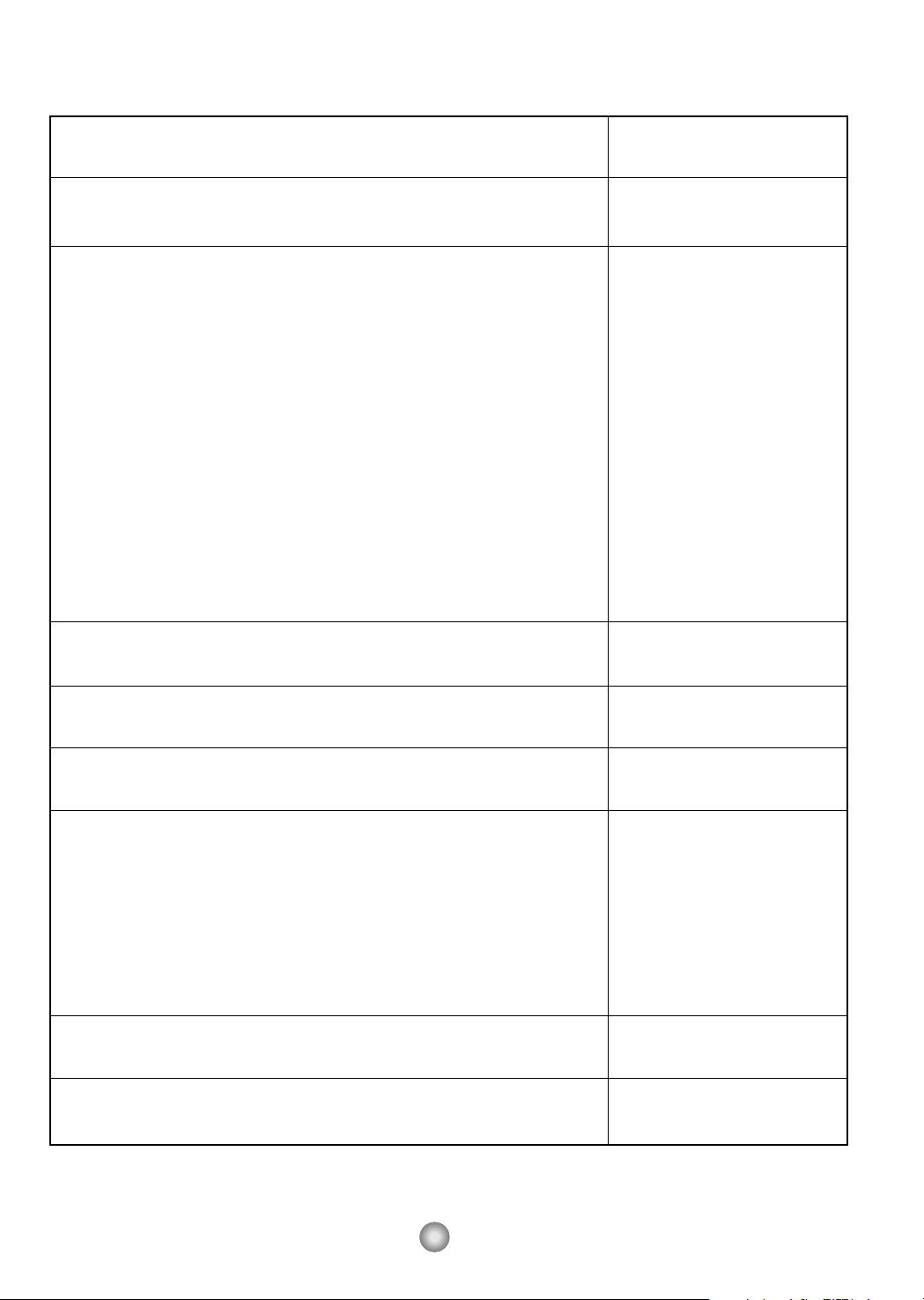
57
Model
Modèle
Modelo
COOLING CAPACITY Btu/h 8,000
CAPACITÉ DE REFROIDISSEMENT
CAPACIDAD DE ENFRIAMIENTO
ELECTRICAL RATING Phase Single
CARACTÉRISTIQUES ÉLECTRIQUES Phase Simple
CLASIFICION DE LA ELECTRICIDAD Fase Monofasico
Frequency (Hz) 60
Fréquence
Frecuencia
Voltage (V) 11
Tension
Voltaja
Current (Amps) 7.6
Courant (A)
Corriente (Amps)
Input (W) 820
Consommation
Potencia
EER
RENDEMENT ÉNERGÉTIQUE 9.8
EER
MOISTURE REMOVAL (Pints/h)
SUPPRESSION D'HUMIDITÉ (pinte/h) 2.3
DESHUMIDIFICACION (Tinta/h)
ROOM CIRCULATION (Cf/min)
CIRCULATION D'AIR (pi/min) 210
CIRCULACION DE AIRE (pie/min)
DIMENSIONS Height cm (inches)
DIMENSIONS Hauteur cm (pouces) 35.3 (13
29
/32)
DIMENSIONES Alto cm (pulgadas)
Width cm (inches)
Largeur cm (pouces) 46.9 (18
15
/32)
Ancho cm (pulgadas)
Depth cm (inches)
Profondeur cm (pouces) 52.5 (20
21
/32)
Profundidad cm (pulgadas)
NET WEIGHT kg (Ib)
POIDS NET kg (livres) 29 (64)
PESO NETO kb (libras)
GROSS WEIGHT kg (Ib)
POIDS BRUT kg (livres) 32 (70)
PESO BRUTO kb (libras)
PRODUCT SPECIFICATION
SPÉCIFICATIONS
ESPECIFICIONES DEL PRODUCTO
* Specifications are subject to change without notice for improvement.
* Les spécifications ci-dessus peuvent être changées sans préavis.
* Las especificacionas están sujetas a cambios por majoras sin previo aviso.
CW-C84GU
CW-XC84GU
Ref: Acwar 11/03
58
Ref.: AcwarFr 11/03
59

Panasonic Room Air Conditioner
Limited Warranty
Panasonic Consumer Electronics Company or Panasonic Sales Company (collectively referred to as "the Warrantor") will repair
this product with new or refurbished parts in case of defects in material or workmanship, free of charge, in the USA or Puerto
Rico in accordance to the following (All time periods start from the date of the original purchase).
SEALED REFRIGERATING SYSTEM (compressor and interconnecting tube): FIVE (5) YEARS - PARTS AND LABOR
ALL OTHER COMPONENTS: ONE (1) YEAR - PARTS AND LABOR
In-home service in the USA can be obtained during the warranty period by contacting a Panasonic Service Company (PASC)
Factory Servicenter listed in the Servicenter Directory. Or call toll free, 1-800-211-PANA(7262), to locate a PASC authorized
Servicenter. In-home service in Puerto Rico can be obtained during the warranty period by calling the Panasonic Sales Company
telephone number listed in the Servicenter Directory.
Note: If the unit is installed at the other than normal window height and/or has been
custom-installed (e.g., through the wall), the customer is responsible for removing
the unit from its installation prior to the performance of in-home service.
This warranty is extended only to the original purchaser. A purchase receipt or other proof of date of the original purchase is
required for service and parts replacement under this warranty.
This warranty only covers failures due to defects in materials and workmanship and does not cover normal wear or cosmetic
damage. The warranty does not cover damages which occur in shipment, or failures which are caused by products not supplied by
the warrantor, or failures which result from accident, misuse, abuse, neglect, mishandling, misapplication, faulty installation,
maladjustment of customer controls, improper maintenance, alteration, modification, power line surge, lightning damage,
improper voltage supply, commercial use such as hotel, office, restaurant, or other business or rental use of the product, or service
by anyone other than a PASC Factory Servicenter or a PASC authorized Servicenter, or damage that is attributable to acts of God.
LIMITS AND EXCLUSIONS
There are no express warranties except as listed above.
THE WARRANTOR SHALL NOT BE LIABLE FOR INCIDENTAL OR CONSEQUENTIAL DAMAGES RESULTING
FROM THE USE OF THIS PRODUCT, OR ARISING OUT OF ANY BREACH OF THIS WARRANTY ALL EXPRESS AND
IMPLIED WARRANTIES, INCLUDING THE WARRANTIES OF MERCHANTABILITY, ARE LIMITED TO THE
APPLICABLE WARRANTY PERIOD SET FORTH ABOVE.
Some states do not allow the exclusion or limitation of incidental or consequential damages or limitations on how long an
implied warranty lasts, so the above exclusions or limitations may not apply to you.
This warranty gives you specific legal rights and you may also have other rights which vary from state to state If a problem with
this product develops during or after the warranty period, you may contact your dealer or Servicenter If the problem is not
handled to your satisfaction, then write to the Consumer Affairs Department at the company address indicated above
SERVICE CALLS WHICH DO NOT INVOLVE DEFECTIVE MATERIALS OR WORKMANSHIP AS DETERMINED BY
THE WARRANTOR, IN ITS SOLE DISCRETION, ARE NOT COVERED COSTS OF SUCH SERVICE CALLS ARE THE
RESPONSIBILITY OF THE PURCHASER.
[For assistance, please call: 1-800-21 1-PANA (7262) or send e-mail to [email protected]]
Printed in Korea
Panasonic Consumer Electronics Company,
Division of Matsushita Electric Corporation
of America
One Panasonic Way
Secaucus, New Jersey 07094
Panasonic Sales Company,
Division of Matsushita Electric of Puerto Rico, Inc.,
Ave. 65 de Infanteria, Km. 9.5
San Gabriel Industrial Park
Carolina, Puerto Rico 00985

This file has been downloaded from:
www.UsersManualGuide.com
User Manual and User Guide for many equipments like mobile phones, photo cameras, monther board, monitors, software, tv, dvd, and othes..
Manual users, user manuals, user guide manual, owners manual, instruction manual, manual owner, manual owner's, manual guide,
manual operation, operating manual, user's manual, operating instructions, manual operators, manual operator, manual product,
documentation manual, user maintenance, brochure, user reference, pdf manual