© Panasonic Corporation 2016.
Order No: PAPAMY1601004CE
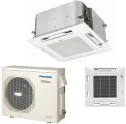
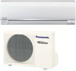
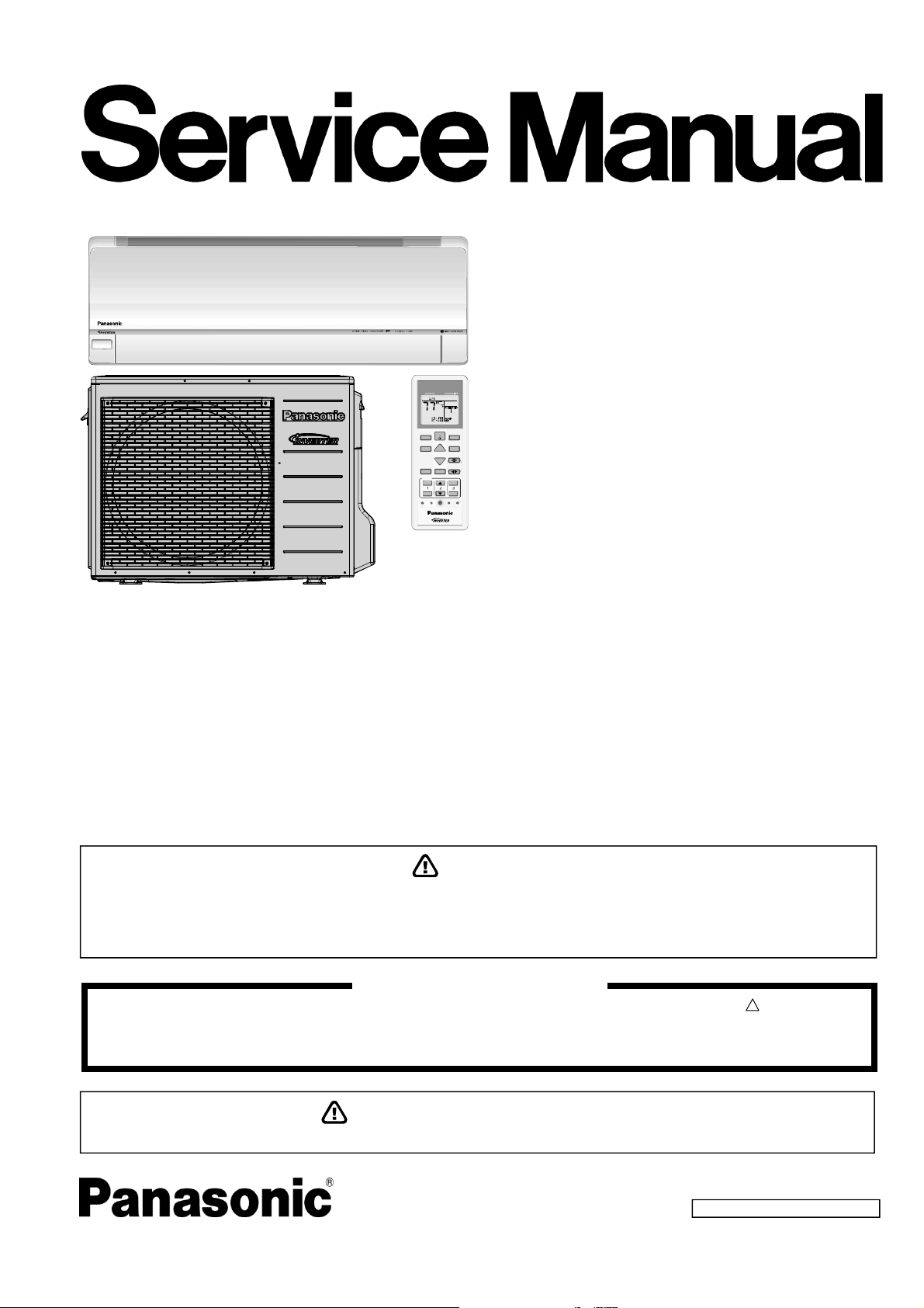
Air Conditioner
Indoor Unit Outdoor Unit
CS-XE9SKUA
CS-XE12SKUA
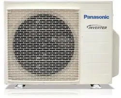
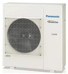
CU-XE9SKUA
CU-XE12SKUA
Destination
U.S.A.
Canada
CLOCK
AIR CONDITIONER
OFF/ON
SET CHECK RESET
AC
RC
ON
OFF
SET
123
TIMER
AUTO
COMFORT
POWERF UL /
QUIET
MODE
TEMP
FAN SPEED
AIR SWING
ECONA VI
RFP
MODE
O
FF/
O
N
C
HE
C
K
O
N
O
FF
S
ET
1
2
3
T
I
M
E
R
T
E
M
P
CANCEL
IMPORT
A
NT S
A
FETY NOTICE
There are special components used in this equipment which are important for safety. These parts are marked by in the Schematic
Diagrams, Circuit Board Diagrams, Exploded Views and Replacement Parts List. It is essential that these critical parts should be replaced
with manufacturer’s specified parts to prevent shock, fire or other hazards. Do not modify the original design without permission of
manufacturer.
!
This service information is designed for experienced repair technicians only and is not designed for use by the general public.
It does not contain warnings or cautions to advise non-technical individuals of potential dangers in attempting to service a product.
Products powered by electricity should be serviced or repaired only by experienced professional technicians. Any attempt to service
or repair the products dealt with in this service information by anyone else could result in serious injury or death.
WARNING
PRECAUTION OF LOW TEMPERATURE
In order to avoid frostbite, be assured of no refrigerant leakage during the installation or repairing of refrigerant circuit.

2
TABLE OF CONTENTS
1. Safety Precautions ............................................. 3
2. Specifications ..................................................... 5
3. Features ............................................................. 11
4. Location of Controls and Components .......... 12
4.1 Indoor Unit .................................................. 12
4.2 Outdoor Unit ............................................... 12
4.3 Remote Control .......................................... 12
5. Dimensions ....................................................... 13
5.1 Indoor Unit .................................................. 13
5.2 Outdoor Unit ............................................... 14
6. Refrigeration Cycle Diagram ........................... 15
7. Block Diagram .................................................. 16
8. Wiring Connection Diagram ............................ 17
8.1 Indoor Unit .................................................. 17
8.2 Outdoor Unit ............................................... 18
9. Electronic Circuit Diagram .............................. 19
9.1 Indoor Unit .................................................. 19
9.2 Outdoor Unit ............................................... 20
10. Printed Circuit Board ....................................... 21
10.1 Indoor Unit .................................................. 21
10.2 Outdoor Unit ............................................... 23
11. Installation Instruction ..................................... 24
11.1 Select the Best Location ............................. 24
11.2 Indoor Unit .................................................. 25
11.3 Outdoor Unit ............................................... 29
12. Operation Control ............................................. 33
12.1 Basic Function ............................................ 33
12.2 Indoor Fan Motor Operation ....................... 34
12.3 Outdoor Fan Motor Operation .................... 35
12.4 Airflow Direction .......................................... 36
12.5 Quiet operation (Cooling Mode/Cooling
area of Dry Mode) ....................................... 37
12.6 Quiet Operation (Heating) .......................... 37
12.7 Powerful Mode Operation ........................... 38
12.8 Timer Control .............................................. 38
12.9 Auto Restart Control ................................... 38
12.10 Indication Panel .......................................... 39
12.11 Room Freeze Protection Function (RFP)
Operation .................................................... 39
12.12 AUTO COMFORT and ECONAVI
Operation .................................................... 39
13. Protection Control ............................................ 43
13.1 Protection Control For All Operations ......... 43
13.2 Protection Control For Cooling & Soft Dry
Operation .................................................... 45
13.3 Protection Control For Heating
Operation .................................................... 46
14. Servicing Mode ................................................. 48
14.1 Auto OFF/ON Button .................................. 48
14.2 Remote Control Button ............................... 49
15. Troubleshooting Guide ....................................50
15.1 Refrigeration Cycle System ........................50
15.2 Breakdown Self Diagnosis Function ...........52
15.3 Error Codes Table ......................................53
15.4 Self-diagnosis Method ................................55
16. Disassembly and Assembly Instructions ......82
16.1 Indoor Electronic Controllers,
Cross Flow Fan and Indoor Fan Motor
Removal Procedures ..................................82
16.2 Outdoor Electronic Controller Removal
Procedure ...................................................86
17. Technical Data ..................................................87
17.1 Cool Mode Performance Data ....................87
17.2 Heat Mode Performance Data ....................89
18. Service Data ......................................................90
18.1 Cool Mode Outdoor Air Temperature
Characteristic ..............................................90
18.2 Heat Mode Outdoor Air Temperature
Characteristic ..............................................92
18.3 Piping Length Correction Factor .................94
19. Exploded View and Replacement Parts
List .....................................................................95
19.1 Indoor Unit ..................................................95
19.2 Outdoor Unit ...............................................98
3
1. Safety Precautions
Read the following “SAFETY PRECAUTIONS” carefully before perform any servicing.
Electrical work must be installed or serviced by a licensed electrician. Be sure to use the correct rating of the power plug and
main circuit for the model installed.
The caution items stated here must be followed because these important contents are related to safety. The meaning of each
indication used is as below. Incorrect installation or servicing due to ignoring of the instruction will cause harm or damage,
and the seriousness is classified by the following indications.
WARNING
This indication shows the possibility of causing death or serious injury.
CAUTION
This indication shows the possibility of causing injury or damage to properties.
The items to be followed are classified by the symbols:
This symbol denotes item that is PROHIBITED from doing.
Carry out test run to confirm that no abnormality occurs after the servicing. Then, explain to user the operation, care and
maintenance as stated in instructions. Please remind the customer to keep the operating instructions for future reference.
WARNING
1. Do not modify the machine, part, material during repairing service.
2. If wiring unit is supplied as repairing part, do not repair or connect the wire even only partial wire break. Exchange the whole wiring unit.
3. Do not wrench the fasten terminal. Pull it out or insert it straightly.
4.
Engage dealer or specialist for installation and servicing. If installation of servicing done by the user is defective, it will cause water
leakage, electrical shock or fire.
5. Install according to this installation instructions strictly. If installation is defective, it will cause water leakage, electric shock or fire.
6.
Use the attached accessories parts and specified parts for installation and servicing. Otherwise, it will cause the set to fall, water leakage,
fire or electrical shock.
7.
Install at a strong and firm location which is able to withstand the set’s weight. If the strength is not enough or installation is not properly
done, the set will drop and cause injury.
8.
For electrical work, follow the local national wiring standard, regulation and the installation instruction. An independent circuit and single
outlet must be used. If electrical circuit capacity is not enough or defect found in electrical work, it will cause electrical shock or fire.
9.
This equipment must installed with an Earth Leakage Circuit Breaker (ELCB) or Ground Fault Current Interrupter (GFCI) or Appliance
Leakage Current Interrupter (ALCI) that has been certified by an NRTL Certified Testing Agency and that is suitable for the voltages and
amperages involved. Otherwise, if may cause electrical shock and fire in case of equipment breakdown.
10.
Do not use joint cable for indoor / outdoor connection cable. Use the specified Indoor/Outdoor connection cable, refer to installation
instruction CONNECT THE CABLE TO THE INDOOR UNIT and connect tightly for indoor / outdoor connection. Clamp the cable so that
no external force will be acted on the terminal. If connecting or fixing is not perfect, it will cause heat up or fire at the connection.
11.
Wire routing must be properly arranged so that control board cover is fixed properly. If control board cover is not fixed perfectly, it will
cause heat-up or fire at the connection point of terminal, fire or electrical shock.
12.
When install or relocate air conditioner, do not let any substance other than the specified refrigerant, eg. air etc. mix into refrigeration
cycle (piping). (Mixing of air etc. will cause abnormal high pressure in refrigeration cycle and result in explosion, injury etc.).
13.
Do not install outdoor unit near handrail of veranda. When installing air-conditioner unit at veranda of high rise building, child may climb
up to outdoor unit and cross over the handrail and causing accident.
14.
This equipment must be properly earthed. Earth line must not be connected to gas pipe, water pipe, earth of lightning rod and
telephone. Otherwise, it may cause electric shock in case equipment breakdown or insulation breakdown.
15. Keep away from small children, the thin film may cling to nose and mouth and prevent breathing.
16.
Do not use unspecified cord, modified cord, joint cord or extension cord for power supply cord. Do not share the single outlet with
other electrical appliances. Poor contact, poor insulation or over current will cause electrical shock or fire.
17.
Tighten the flare nut with torque wrench according to specified method. If the flare nut is over-tightened, after a long period, the
flare may break and cause refrigerant gas leakage.
18.
For R410A model, use piping, flare nut and tools which is specified for R410A refrigerant. Using of existing (R22) piping, flare nut
and tools may cause abnormally high pressure in the refrigerant cycle (piping), and possibly result in explosion and injury.
Thickness or copper pipes used with R410A must be more than 1/32" (0.8 mm). Never use copper pipes thinner than 1/32"
(0.8 mm). It is desirable that the amount of residual oil is less than 0.0008 oz/ft (40 mg/10 m).
19.
During installation, install the refrigerant piping properly before run the compressor. (Operation of compressor without fixing refrigeration
piping and valves at opened condition will caused suck-in of air, abnormal high pressure in refrigeration cycle and result in explosion,
injury etc).
4
WARNING
20.
During pump down operation, stop the compressor before remove the refrigeration piping. (Removal of compressor while compressor is
operating and valves are opened will cause suck-in of air, abnormal high pressure in refrigeration cycle and result in explosion, injury etc.)
21.
After completion of installation or service, confirm there is no leakage or refrigerant gas. It may generate toxic gas when the refrigerant
contacts with fire.
22. Ventilate if there is refrigerant gas leakage during operation. It may cause toxic gas when refrigerant contacts with fire.
23. Do not insert your fingers or other objects into the unit, high speed rotating fan may cause injury.
24. Must not use other parts except original parts described in catalog and manual.
25. Using of refrigerant other than the specified type may cause product damage, burst and injury etc.
CAUTION
1.
Do not install the unit at place where leakage of flammable gas may occur. In case gas leaks and accumulates at surrounding of
the unit, it may cause fire.
2.
Carry out drainage piping as mentioned in installation instructions. If drainage is not perfect, water may enter the room and damage the
furniture.
3.
Tighten the flare nut with torque wrench according to specified method. If the flare nut is over-tightened, after a long period, the flare may
break and cause refrigerant gas leakage.
4. Do not touch outdoor unit air inlet and aluminium fin. It may cause injury.
5. Select an installation location which is easy for maintenance.
6.
Pb free solder has a higher melting point than standard solder; typically the melting point is 50°F – 70°F (30°C – 40°C) higher.
Please use a high temperature solder iron. In case of the soldering iron with temperature control, please set it to 700 ± 20°F (370 ± 10°C).
Pb free solder will tend to splash when heated too high (about 1100°F / 600°C).
7.
Power supply connection to the room air conditioner.
Power supply cord shall be UL listed or CSA approved 3 conductor with minimum AWG14 wires.
Power supply point should be in an easily accessible place for power disconnection in case of emergency.
In some countries, permanent connection of this air conditioner to the power supply is prohibited.
Fix power supply connection to a circuit breaker for permanent connection.
Use NRTL approved fuse or circuit breaker (rating refers to name plate) for permanent connection.
8.
Do not release refrigerant during piping work for installation, servicing, reinstallation and during repairing a refrigerant parts.
Take care of the liquid refrigerant, it may cause frostbite.
9. Installation or servicing work: It may need two people to carry out the installation or servicing work.
10. Do not install this appliance in a laundry room or other location where water may drip from the ceiling, etc.
11. Do not sit or step on the unit, you may fall down accidentally.
12.
Do not touch the sharp aluminium fins or edges of metal parts.
If you are required to handle sharp parts during installation or servicing, please wear hand glove.
Sharp parts may cause injury.
5
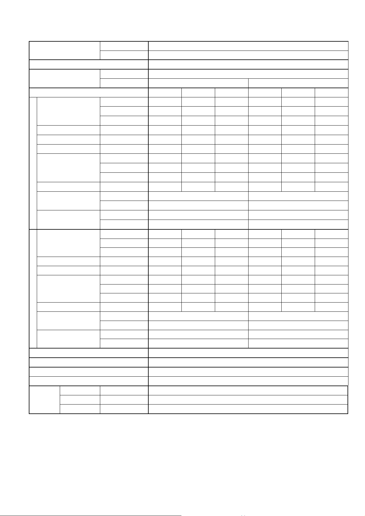
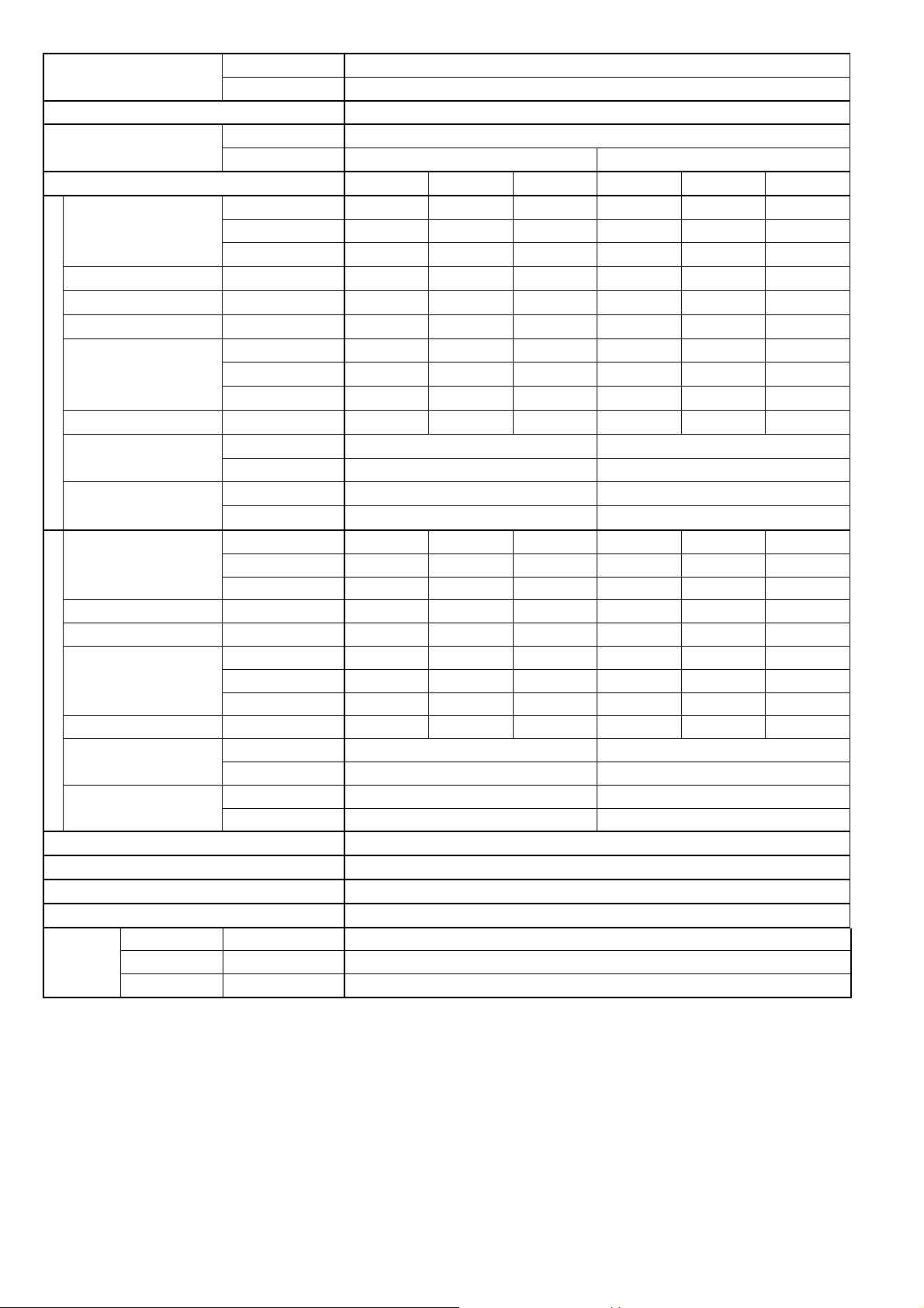
2. Specifications
Model
Indoor CS-XE9SKUA
Outdoor CU-XE9SKUA
Performance Test Condition ARI
Power Supply
Phase, Hz Single, 60
V 208 230
Min. Mid. Max. Min. Mid. Max.
Cooling
Capacity
kW 0.83 2.55 3.51 0.83 2.55 3.51
BTU/h 2800 8700 12000 2800 8700 12000
kcal/h – – – – – –
Running Current A – 2.70 – – 2.40 –
Input Power W 150 510 850 150 510 850
Annual Consumption kWh – – – – – –
EER
W/W 5.53 5.00 4.13 5.53 5.00 4.13
BTU/hW 18.65 17.05 14.10 18.65 17.05 14.10
kcal/hW – – – – – –
Power Factor % – 91 – – 92 –
Indoor Noise (H / L / QLo)
dB-A 42 / 25 / 20 42 / 25 / 20
Power Level dB 58 / – / – 58 / – / –
Outdoor Noise (H / L / QLo)
dB-A 48 / – / – 48 / – / –
Power Level dB 63 / – / – 63 / – / –
Heating
Capacity
kW 0.89 3.21 5.29 0.89 3.21 5.29
BTU/h 3000 10900 18000 3000 10900 18000
kcal/h – – – – – –
Running Current A – 3.50 – – 3.10 –
Input Power W 150 670 1.65k 150 670 1.65k
COP
W/W 5.93 4.78 3.21 5.93 4.78 3.21
BTU/hW 20.00 16.25 10.90 20.00 16.25 10.90
kcal/hW – – – – – –
Power Factor % – 92 – – 94 –
Indoor Noise (H / L / QLo)
dB-A 42 / 29 / 26 42 / 29 / 26
Power Level dB 58 / – / – 58 / – / –
Outdoor Noise (H / L / QLo)
dB-A 48 / – / – 48 / – / –
Power Level dB 63 / – / – 63 / – / –
17°F: Rated Capacity (BTU/h) / I. Power (W) 8000 / 750
5°F: Max. Capacity (BTU/h) 11000
Max Current (A) / Max Input Power (W) 7.8 / 1.71k
Starting Current (A) 3.50
Compressor
Type Hermetic Motor (Rotary)
Motor Type Brushless (4 poles)
Output Power W 700
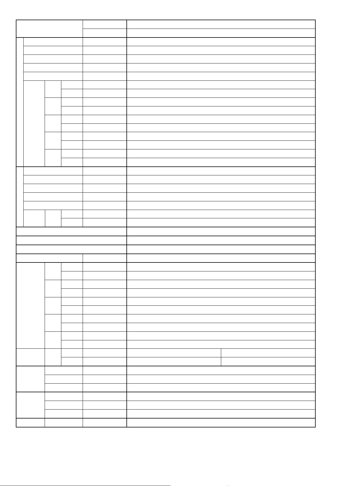
6
Model
Indoor CS-XE9SKUA
Outdoor CU-XE9SKUA
Indoor Fan
Type Cross-Flow Fan
Material ASG33
Motor Type DC / Transistor (8-poles)
Input Power W 47.0
Output Power W 40
Speed
QLo
Cool rpm 570
Heat rpm 730
Lo
Cool rpm 660
Heat rpm 790
Me
Cool rpm 920
Heat rpm 990
Hi
Cool rpm 1180
Heat rpm 1190
SHi
Cool rpm 1250
Heat rpm 1340
Outdoor Fan
Type Propeller Fan
Material PP
Motor Type DC (8-poles)
Input Power W –
Output Power W 40
Speed Hi
Cool rpm 600
Heat rpm 670
Min Circuit Ampacity 15.0
Max. Overcurrent Protection 15.0
SEER / HSPF 30.60 / 14.00
Moisture Removal L/h (Pt/h) 0.5 (1.3)
Indoor
Airflow
QLo
Cool m
3
/min (ft
3
/min) 5.77 (203)
Heat m
3
/min (ft
3
/min) 7.79 (275)
Lo
Cool m
3
/min (ft
3
/min) 6.88 (242)
Heat m
3
/min (ft
3
/min) 8.53 (301)
Me
Cool m
3
/min (ft
3
/min) 10.09 (356)
Heat m
3
/min (ft
3
/min) 11.01 (388)
Hi
Cool m
3
/min (ft
3
/min) 13.3 (470)
Heat m
3
/min (ft
3
/min) 13.5 (475)
SHi
Cool m
3
/min (ft
3
/min) 14.16 (500)
Heat m
3
/min (ft
3
/min) 15.36 (540)
Outdoor
Airflow
Hi
Cool m
3
/min (ft
3
/min) 34.6 (1220) 34.6 (1220)
Heat m
3
/min (ft
3
/min) 39.1 (1380) 39.1 (1380)
Refrigeration
Cycle
Control Device Expansion Valve
Refrigerant Oil cm
3
FV50S (320)
Refrigerant Type g (oz) R410A, 1150 (40.6)
Dimension
Height(I/D / O/D) mm (inch) 295 (11-5/8) / 695 (27-3/8)
Width (I/D / O/D) mm (inch) 870 (34-9/32) / 875 (34-15/32)
Depth (I/D / O/D) mm (inch) 255 (10-1/16) / 320 (12-5/8)
Weight Net (I/D / O/D) kg (lb) 11 (24) / 44 (97)
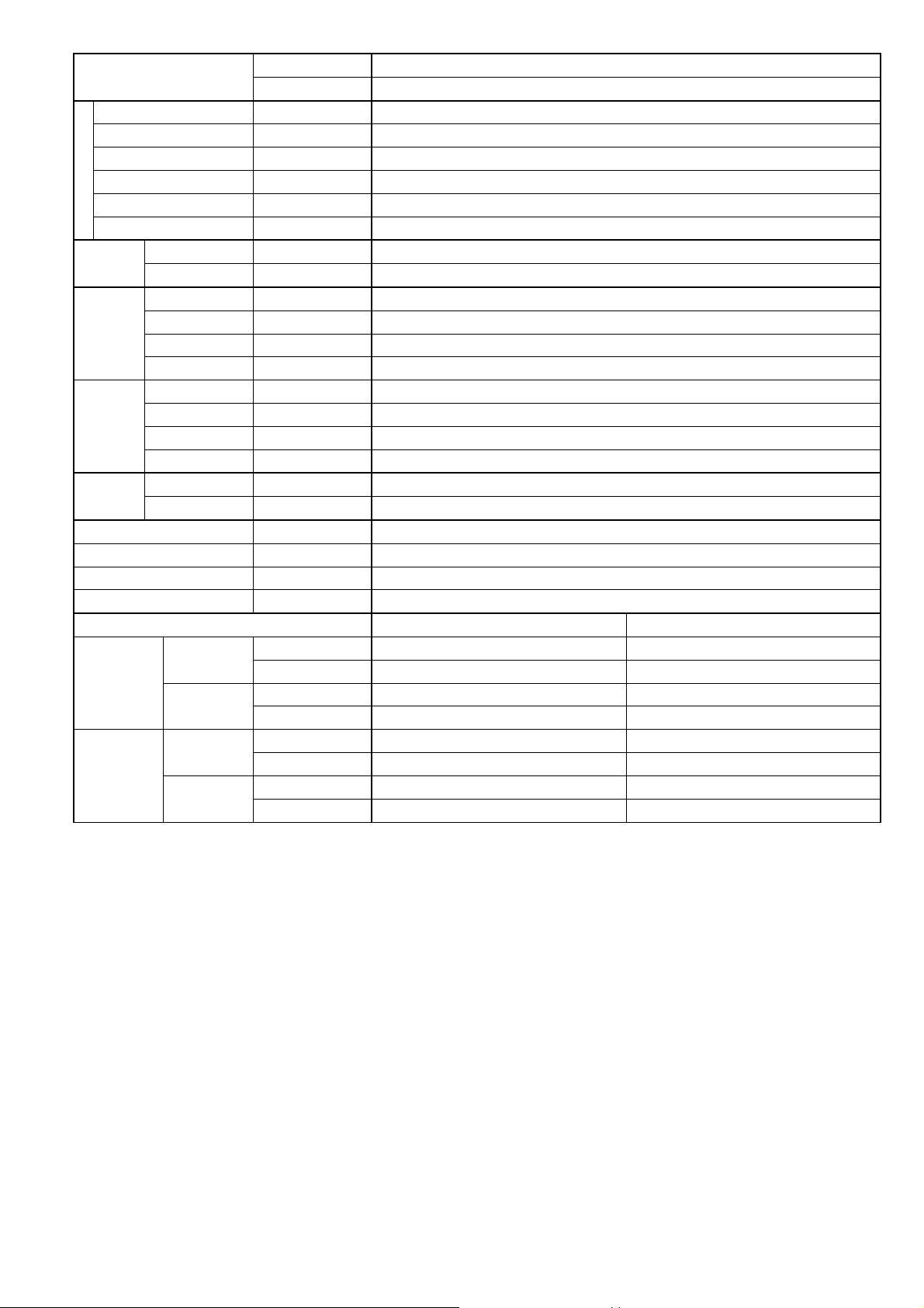
7
Model
Indoor CS-XE9SKUA
Outdoor CU-XE9SKUA
Piping
Pipe Diameter (Liquid / Gas) mm (inch) 6.35 (1/4) / 9.52 (3/8)
Standard length m (ft) 7.5 (24.6)
Length range (min – max) m (ft) 3 (9.8) ~ 20 (65.6)
I/D & O/D Height different m (ft) 15.0 (49.2)
Additional Gas Amount g/m (oz/ft) 20 (0.2)
Length for Additional Gas m (ft) 7.5 (24.6)
Drain Hose
Inner Diameter mm (inch) 16.7 (5/8)
Length mm(inch) 650 (25-5/8)
Indoor Heat
Exchanger
Fin Material Aluminium (Pre Coat)
Fin Type Slit Fin
Row × Stage × FPI 2 × 17 × 21
Size (W × H × L) mm (inch) 636.5 × 357 × 25.4 (25-1/16 × 14-1/16 × 1)
Outdoor
Heat
Exchanger
Fin Material Aluminium / Blue Coated
Fin Type Corrugated Fin
Row × Stage × FPI 2 × 31 × 18
Size (W × H × L) mm (inch) 36.4 × 651 × 854.5:824.5 (1-7/16 × 25-11/16 × 33-11/16:32-15/32)
Air Filter
Material Polypropelene
Type One-touch
Power Supply Outdoor
Power Supply Cord A Nil
Thermostat Electronic Control
Protection Device Electronic Control
Dry Bulb Wet Bulb
Indoor
Operation
Range
Cooling
Maximum °F/°C 89.6/32 73.4/23
Minimum °F/°C 60.8/16 51.8/11
Heating
Maximum °F/°C 86.0/30 –/–
Minimum °F/°C 60.8/16 –/–
Outdoor
Operation
Range
Cooling
Maximum °F/°C 114.8/46 78.8/26
Minimum °F/°C 0.0/-17.8 –/–
Heating
Maximum °F/°C 75.2/24 64.4/18
Minimum °F/°C -15/-26 -2.2/-19
1. Cooling capacities are based on indoor temperature of 80°F (26.7°C) DRY BULB, 67°F (19.4°C) WET BULB and outdoor air temperature of
95°F (35°C) DRY BULB, 75°F (23.8°C) WET BULB.
2. Heating capacities are based on indoor temperature of 70°F (21.1°C) DRY BULB, 60°F (15.6°C) WET BULB and outdoor air temperature of
47°F (8.3°C) DRY BULB, 43°F (6.1°C) WET BULB.
3. 17°F (-8.3°C) Heating Capacity and Input Power measured at 230V, indoor temperature 70°F (21.1°C), outdoor 17/15°F (-8.3/-9.4°C).
4. 5°F (-15°C) Heating Capacity measured at 230V, indoor temperature 70°F (21.1°C), outdoor 5°F (-15°C/-).
5. Specifications are subjected to change without prior notice for further improvement.
8
Model
Indoor CS-XE12SKUA
Outdoor CU-XE12SKUA
Performance Test Condition ARI
Power Supply
Phase, Hz Single, 60
V 208 230
Min. Mid. Max. Min. Mid. Max.
Cooling
Capacity
kW 0.83 3.36 4.10 0.83 3.36 4.10
BTU/h 2800 11500 14000 2800 11500 14000
kcal/h – – – – – –
Running Current A – 4.10 – – 3.70 –
Input Power W 150 780 1.05k 150 780 1.05k
Annual Consumption kWh – – – – – –
EER
W/W 5.53 4.30 3.90 5.53 4.30 3.90
BTU/hW 18.65 14.70 13.30 18.65 14.70 13.30
kcal/hW – – – – – –
Power Factor % – 91 – – 92 –
Indoor Noise (H / L / QLo)
dB-A 45 / 28 / 20 45 / 28 / 20
Power Level dB 61 / – / – 61 / – / –
Outdoor Noise (H / L / QLo)
dB-A 49 / – / – 49 / – / –
Power Level dB 64 / – / – 64 / – / –
Heating
Capacity
kW 0.89 3.99 6.72 0.89 3.99 6.72
BTU/h 3000 13600 23000 3000 13600 23000
kcal/h – – – – – –
Running Current A – 4.90 – – 4.40 –
Input Power W 150 950 2.10k 150 950 2.10k
COP
W/W 5.93 4.20 3.20 5.93 4.20 3.20
BTU/hW 20.00 14.30 10.95 20.00 14.30 10.95
kcal/hW – – – – – –
Power Factor % – 93 – – 94 –
Indoor Noise (H / L / QLo)
dB-A 44 / 35 / 32 44 / 35 / 32
Power Level dB 60 / – / – 60 / – / –
Outdoor Noise (H / L / QLo)
dB-A 49 / – / – 49 / – / –
Power Level dB 64 / – / – 64 / – / –
17°F: Rated Capacity (BTU/h) / I. Power (W) 10400 / 1.05k
5°F: Max. Capacity (BTU/h) 12500
Max Current (A) / Max Input Power (W) 9.5 / 2.15k
Starting Current (A) 4.90
Compressor
Type Hermetic Motor (Rotary)
Motor Type Brushless (4 poles)
Output Power W 700
9
Model
Indoor CS-XE12SKUA
Outdoor CU-XE12SKUA
Indoor Fan
Type Cross-Flow Fan
Material ASG33
Motor Type DC / Transistor (8-poles)
Input Power W 47.0
Output Power W 40
Speed
QLo
Cool rpm 570
Heat rpm 870
Lo
Cool rpm 710
Heat rpm 950
Me
Cool rpm 990
Heat rpm 1100
Hi
Cool rpm 1280
Heat rpm 1250
SHi
Cool rpm 1350
Heat rpm 1340
Outdoor Fan
Type Propeller Fan
Material PP
Motor Type DC (8-poles)
Input Power W –
Output Power W 40
Speed Hi
Cool rpm 600
Heat rpm 730
Min Circuit Ampacity 15.0
Max. Overcurrent Protection 20.0
SEER / HSPF 26.20 / 12.50
Moisture Removal L/h (Pt/h) 1.1 (2.3)
Indoor
Airflow
QLo
Cool m
3
/min (ft
3
/min) 5.83 (205)
Heat m
3
/min (ft
3
/min) 9.56 (338)
Lo
Cool m
3
/min (ft
3
/min) 7.58 (268)
Heat m
3
/min (ft
3
/min) 10.56 (373)
Me
Cool m
3
/min (ft
3
/min) 11.08 (391)
Heat m
3
/min (ft
3
/min) 12.43 (439)
Hi
Cool m
3
/min (ft
3
/min) 14.7 (520)
Heat m
3
/min (ft
3
/min) 14.3 (505)
SHi
Cool m
3
/min (ft
3
/min) 15.57 (550)
Heat m
3
/min (ft
3
/min) 15.42 (544)
Outdoor
Airflow
Hi
Cool m
3
/min (ft
3
/min) 35.9 (1265) 35.9 (1265)
Heat m
3
/min (ft
3
/min) 44.0 (1555) 44.0 (1555)
Refrigeration
Cycle
Control Device Expansion Valve
Refrigerant Oil cm
3
FV50S (320)
Refrigerant Type g (oz) R410A, 1150 (40.6)
Dimension
Height(I/D / O/D) mm (inch) 295 (11-5/8) / 695 (27-3/8)
Width (I/D / O/D) mm (inch) 870 (34-9/32) / 875 (34-15/32)
Depth (I/D / O/D) mm (inch) 255 (10-1/16) / 320 (12-5/8)
Weight Net (I/D / O/D) kg (lb) 11 (24) / 44 (97)
10
Model
Indoor CS-XE12SKUA
Outdoor CU-XE12SKUA
Piping
Pipe Diameter (Liquid / Gas) mm (inch) 6.35 (1/4) / 12.70 (1/2)
Standard length m (ft) 7.5 (24.6)
Length range (min – max) m (ft) 3 (9.8) ~ 20 (65.6)
I/D & O/D Height different m (ft) 15.0 (49.2)
Additional Gas Amount g/m (oz/ft) 20 (0.2)
Length for Additional Gas m (ft) 7.5 (24.6)
Drain Hose
Inner Diameter mm (inch) 16.7 (5/8)
Length mm (inch) 650 (25-5/8)
Indoor Heat
Exchanger
Fin Material Aluminium (Pre Coat)
Fin Type Slit Fin
Row × Stage × FPI 2 × 17 × 21
Size (W × H × L) mm (inch) 636.5 × 357 × 25.4 (25-11/16 × 14-1/16 × 1)
Outdoor
Heat
Exchanger
Fin Material Aluminium / Blue Coated
Fin Type Corrugated Fin
Row × Stage × FPI 2 × 31 × 18
Size (W × H × L) mm (inch) 36.4 × 651 × 854.5:824.5 (1-7/16 × 25-11/16 × 33-11/16:32-15/32)
Air Filter
Material Polypropelene
Type One-touch
Power Supply Outdoor
Power Supply Cord A Nil
Thermostat Electronic Control
Protection Device Electronic Control
Dry Bulb Wet Bulb
Indoor
Operation
Range
Cooling
Maximum °F/°C 89.6/32 73.4/23
Minimum °F/°C 60.8/16 51.8/11
Heating
Maximum °F/°C 86.0/30 –/–
Minimum °F/°C 60.8/16 –/–
Outdoor
Operation
Range
Cooling
Maximum °F/°C 114.8/46 78.8/26
Minimum °F/°C 0.0/-17.8 –/–
Heating
Maximum °F/°C 75.2/24 64.4/18
Minimum °F/°C -15/-26 -2.2/-19
1. Cooling capacities are based on indoor temperature of 80°F (26.7°C) DRY BULB, 67°F (19.4°C) WET BULB and outdoor air temperature of
95°F (35°C) DRY BULB, 75°F (23.8°C) WET BULB.
2. Heating capacities are based on indoor temperature of 70°F (21.1°C) DRY BULB, 60°F (15.6°C) WET BULB and outdoor air temperature of
47°F (8.3°C) DRY BULB, 43°F (6.1°C) WET BULB.
3. 17°F (-8.3°C) Heating Capacity and Input Power measured at 230V, indoor temperature 70°F (21.1°C), outdoor 17/15°F (-8.3/-9.4°C).
4. 5°F (-15°C) Heating Capacity measured at 230V, indoor temperature 70°F (21.1°C), outdoor 5°F (-15°C/-).
5. Specifications are subjected to change without prior notice for further improvement.

11
3. Features
Inverter Technology
o Wider output power range
o Energy saving
o Quick Cooling
o Quick Heating
o More precise temperature control
Environment Protection
o Non-ozone depletion substances refrigerant (R410A)
Long Installation Piping
o Long piping up to 65.6ft (20 meters) during single split connection only
Easy to use remote control
Quality Improvement
o Random auto restart after power failure for safety restart operation
o Gas leakage protection
o Prevent compressor reverse cycle
o Inner protector to protect compressor
o Noise prevention during soft dry operation
Operation Improvement
o Quiet mode to reduce the indoor unit operating sound
o Powerful mode to reach the desired room temperature quickly
o 24-hour timer setting
o RFP (Room Freeze Protection) operation is designed to circulate the air in High mode for monitoring the
temperature. Used in spaces that are unoccupied during the winter, for the purpose of protecting any
equipment or appliances which may be destroyed as a result of freezing temperature.
Serviceability Improvement
o Breakdown Self Diagnosis function
12
4. Location of Controls and Components
4.1 Indoor Unit
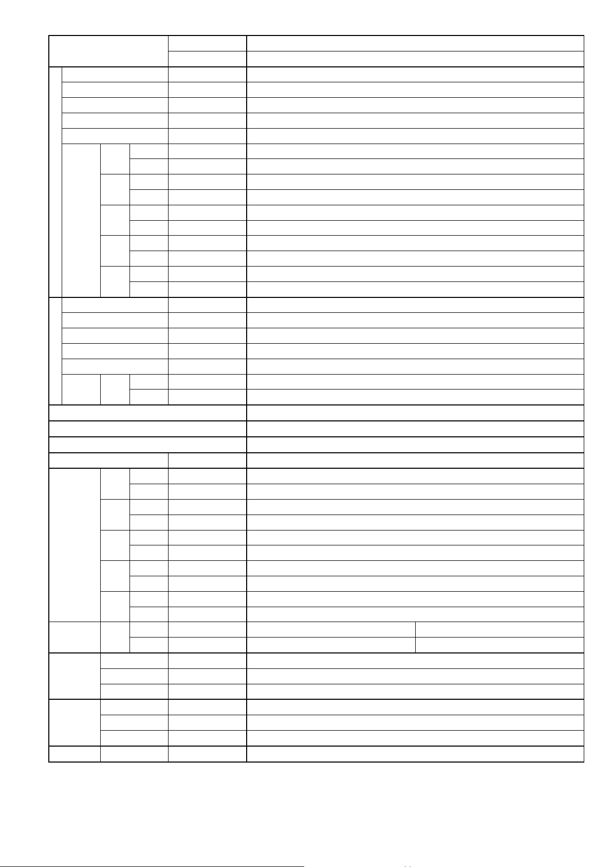
4.2 Outdoor Unit
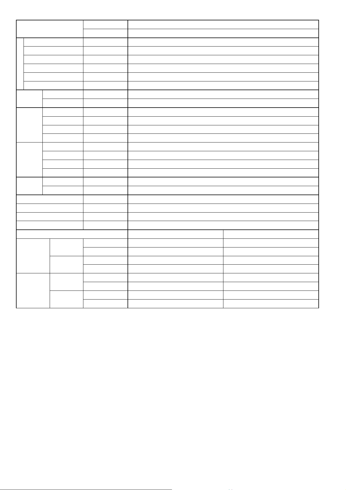
4.3 Remote Control
Front panel
Air Filters
Auto OFF/ON button
Use when remote control is misplaced
or a malfunction occurs.
Aluminium fin
Vertical airflow direction louver
Do not adjust by hand.
Horizontal airflow
direction louver
Do not adjust by hand.
A
ir purifying filter
Human activity
sensor
Remote Control Receiver
Distances: 26ft/8m
Indicator
POW ER
(Green)
AUTO COMFORT
(Green)
RFP
(Green)
QUIET
(Orange)
POW ER FUL
(Orange)
TIMER
(Orange) (Green)
Air inlet (rear)
A
ir outlet
Air inlet (side)
C
L
O
C
K
A
I
R
C
O
N
D
I
T
I
O
N
E
R
O
F
F
/
O
N
S
E
T
C
H
E
C
K
R
E
S
E
T
A
C
R
C
O
N
O
F
F
S
E
T
1
2
3
T
I
M
E
R
A
U
T
O
C
O
M
F
O
R
T
P
O
W
E
R
F
U
L
/
Q
U
I
E
T
M
O
D
E
T
E
M
P
F
A
N
S
P
E
E
D
A
I
R
S
W
I
N
G
E
C
O
N
A
V
I
R
F
P
M
O
D
E
O
F
F
/
O
N
C
H
E
C
K
O
N
O
F
F
S
E
T
1
2
3
T
I
M
E
R
T
E
M
P
C
A
N
C
E
L
LCD display
ECONAVI operation
Operation mode
Room freeze protection operation
OFF/ON
Auto Comfort operation
Airflow direction adjustment
Fan speed selection
Timer setting
Clock setting
Transmitter
Powerful/Quiet
operation
Temperature setting
13
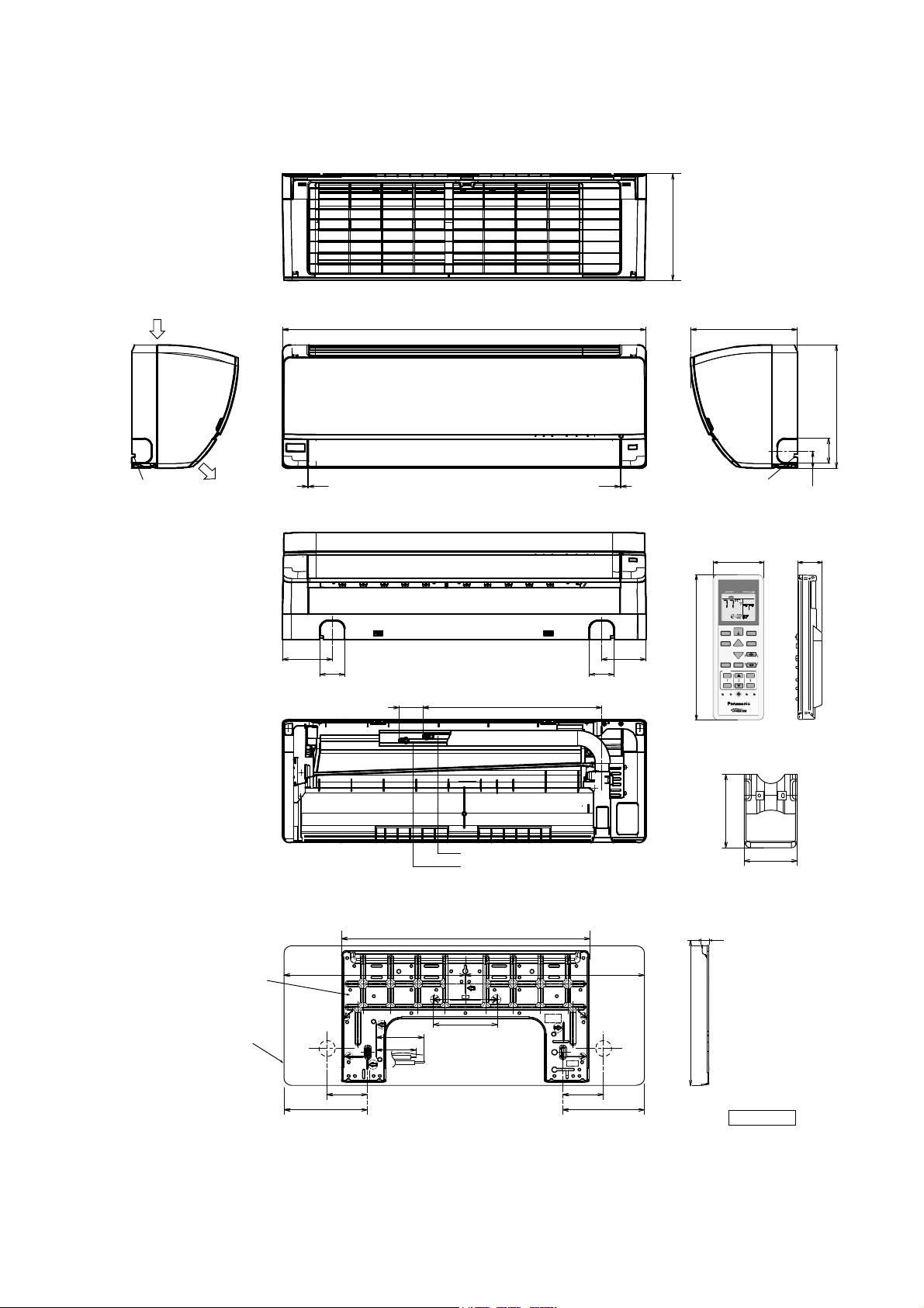
5. Dimensions
5.1 Indoor Unit
<Top View>
<Front View>
<Bottom View>
<Rear View>
Relative position between the indoor unit and the installation plate <Front View>
Gas side
Liquid side
<Side View> <Side View>
Right
piping
hole
Left
piping
hole
Indoor unit
external
dimensions
line
Installation
plate
Unit : inch (mm)
41/64 (16.5)
1-11/16 (43)
3-3/4 (95)
10-1/6 (255)
1/16-3/32 (1-2) 1/16-3/32 (1-2)
Left piping
hole
Air outlet
direction
Air intake
direction
Right piping
hole
4-3/4 (119.1)
4-1/32 (105.8)
2-3/16 (60) 2-3/16 (60)
10-1/16 (255)
11-5/8 (295)
2-3/16 (60)
1-11/16 (41.5)
16-3/16 (410)
10-3/16 (264.2)
1-5/8-2-7/16 (41-61)
3-7/16 (87)
2-17/32 (64)
<Remote Control Holder>
<Remote Control>
6-5/16 (160)
2-5/16 (59)
7/8 (22)
19-19/32 (497.2)
34-9/32 (870)
5-1/16 (128)
5-1/16 (128) 5-1/16 (128)
9-17/32 (241.5) 9-17/32 (241.5)
17 (432)17-9/32 (439)
CLOCK
AIR CONDI TI ONER
OFF/O N
SET CHECK RESET
AC
RC
ON
OFF
SET
123
TIMER
AUTO
COM FORT
POWERFUL/
QUIET
MODE
TEMP
FAN SPEED
AIRSWING
ECO NA VI
RFP
MODE
O
FF/ON
CHECK
O
N
O
FF
S
ET
1
2
3
T
I
M
E
R
T
E
M
P
CANCEL
14
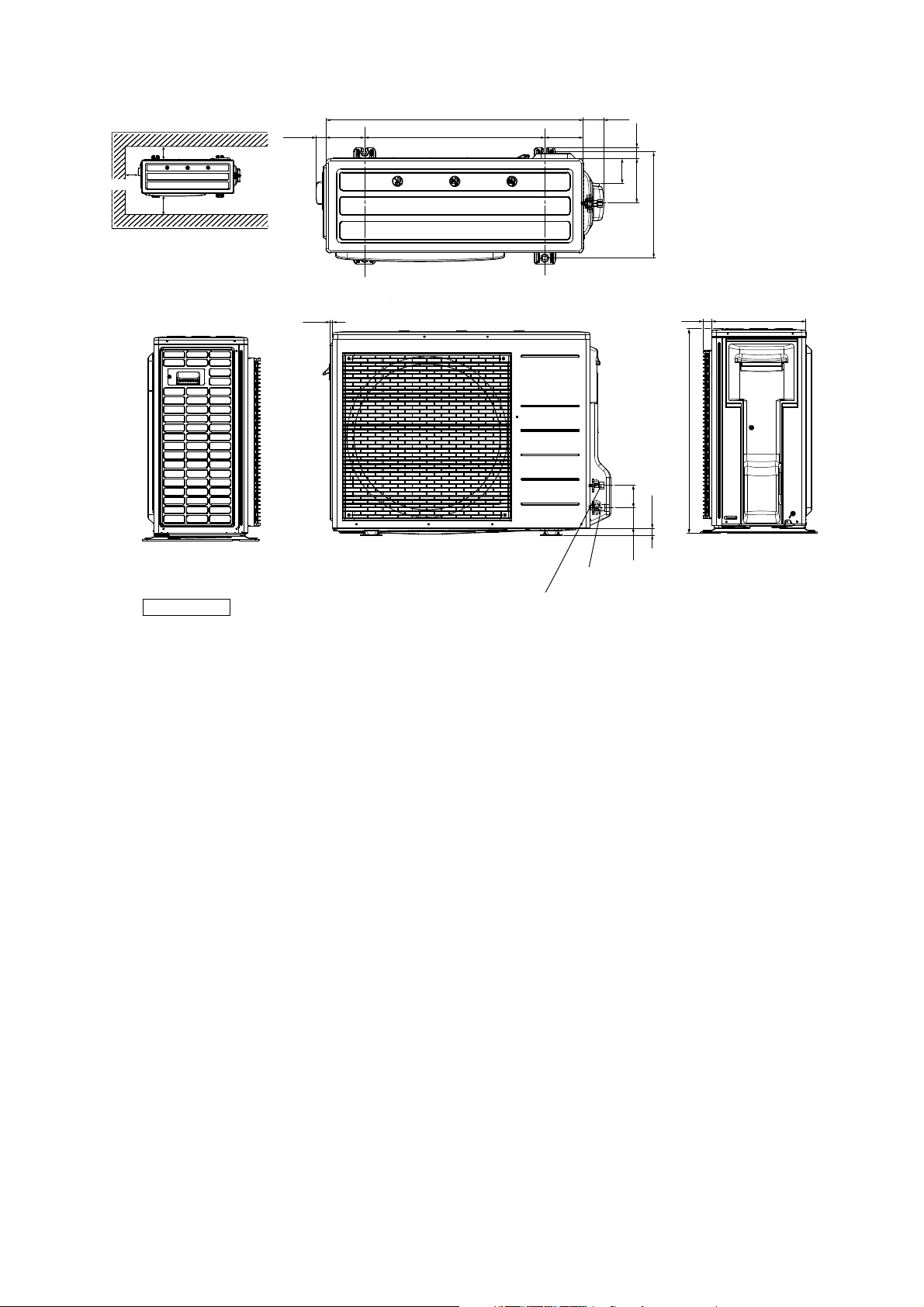
5.2 Outdoor Unit
Unit: inch (mm)
<Sid e View> <Front View>
<
T
o
p
V
ie
w
>
<Side View>
34-15/32 (875)
1-3/8 (34.5)
3/8 (9.5)
2-31/32 (75)
2-25/32 (70.4)
63/64 (25)
5-3/16 (131)
24-5/32 (613)
5-3/16 (131)
1-1/2 (38)
5-31/32 (151)
14-7/32 (360.5)
27-3/8 (695)
3-5/32 (85)
2-25/32 (70)
1-3/16 (30)
12-5/8 (320)
2-way valve at Liquid side
(High Pressure)
3-way valve at Gas side
(Low Pressure)
Anchor Bolt Pitch
14-7/32 (360.5) x 24-5/32 (613)
Space necessary for
installation
3-15/16 (10 cm)
43 (100 cm)
3-15/16 (10 cm)

15
6. Refrigeration Cycle Diagram
INDOOR OUTDOOR
INTAKE
AIR
TEMP.
SENSOR
PIPE
TEMP.
SENSOR 1
PIPE
TEMP.
SENSOR 2
PIPE
TEMP.
SENSOR
AIR
TEMP.
SENSOR
LIQUID
SIDE
2-WAY
VALVE
3-WAY
VALVE
GAS
SIDE
COOLING
HEAT EXCHANGER
(EVAPORATOR)
HEATING
COMPRESSOR
HEAT
EXCHANGER
(CONDENSER)
PROCESS
TUBE
STRAINER
RECEIVER
EXPANSION
VALVE
4-WAYS VALVE
COMPRESSOR
TEMP. SENSOR
MUFFLER
16
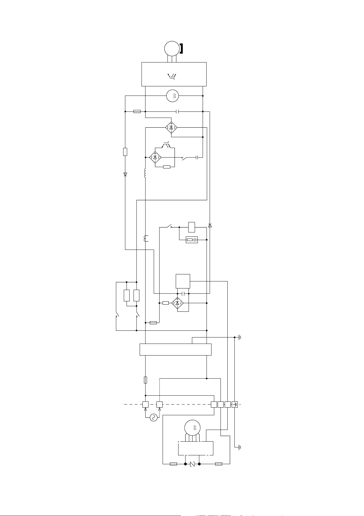
7. Block Diagram
MS
3~
U
P
N
+
DB3
FUSE1
TH2
REACTOR
CT400
PTC1
RY-AC
RY-PWR
PTC2
FUSE2
FUSE 301
SC
TEMPERATURE
FUSE
FUSE3
L1
L2
SINGLE PHASE
POWER SUPPLY
1Ø208/230V, 60Hz
(INDOOR UNIT) (OUTDOOR UNIT)
1
2
3
DB2
NTC
TH1
NTC
DB1
4-WAYS VALVE
RY-C
RY-HOT
CR3
Q1
W
V
M
+
NOISE FILTER
M
17
8. Wiring Connection Diagram
8.1 Indoor Unit
AUTO SW
(SW01)
YLW/GRN
RED
GROUNDING
TERMINAL
3
GRN
WHT
TEMP.FUSE
215.6˚F/102˚C (3A)
TERMINAL
BOARD
2
EVAPORATOR
T
OO
U
T
D
OO
R
U
N
I
T
1
G301(GRN)
AC304(RED)
AC303(WHT)
FUSE301
T3.15A L250V
NOISE FILTER
CIRCUIT
COMMUNICATION
CIRCUIT
RECTIFICATION
CIRCUIT
UP DOWN
LOUVER MOTOR
(OUTER)
M
PIPING TEMP. SENSOR 2
(THERMISTOR)
5
BRW
1
ORG
PNK
RED
5
YLW
1
4
CN-FM
(WHT)
7
1
M
BLK
RED
WHT
BLU
YLW
FAN MOTOR
14
CN-CLN
(GRN)
14
CN-RMT
(WHT)
CN-CNT
(WHT)
51
CN-STM1
(WHT)
LEFT RIGHT
LOUVER MOTOR
M
5
BRW
1
ORG
PNK
RED
5
YLW
1
CN-STM2
(YLW)
1
CN-MSENS
(WHT)
1
CN-STM3
(GRN)
5
3
UP DOWN
LOUVER MOTOR
(INNER)
CN-STM4
(BLU)
SUCTION TEMP.
SENSOR (THERMISTOR)
t
PIPING TEMP. SENSOR 1
(THERMISTOR)
CN-TH
(RED)
1
CN-DISP(YLW)
10
1
6
CN-RCV
(YLW)
14
1
CN-DISP(WHT)
8
ELECTRONIC CONTROLLER
(DISPLAY)
1
4
CN-RCV
(WHT)
ELECTRONIC
CONTROLLER
(RECEIVER)
ELECTRONIC
CONTROLLER
(MAIN)
WHT
REMOTE
CONTROLLER
BLK AC306(BLK)
WHT
WHT
WHT
1
M
BRW
ORG
YLW
5
PNK
5
RED
1
WHT
WHT
WHT
WHT
M
1
1
3
CN-SENS
(GREEN)
CN-STM
(GREEN)
3
CN-SENS
(WHT)
CN-MSSTM
(WHT)
5
ELECTRONIC CONTROLLER
(ECO SENSOR)
1
1
8
ELECTRONIC
ECO SENSOR
MOTOR
CONTROLLER
(COMPARATOR)
51
t
t
REMARKS
BLU:BLUE PNK:PINK
BRW:BROWN ORG:ORANGE
BLK:BLACK YLW:YELLOW
WHT:WHITE GRY:GRAY
RED:RED GRN:GREEN
YLW/GRN:YELLOW/GREEN
WHT
WHT
WHT
YLW
RED
ORG
BRW
PNK
WHT
WHT
WHT
WHT
WHT
WHT
WHT
WHT
WHT
WHT
WHT
WHT

18
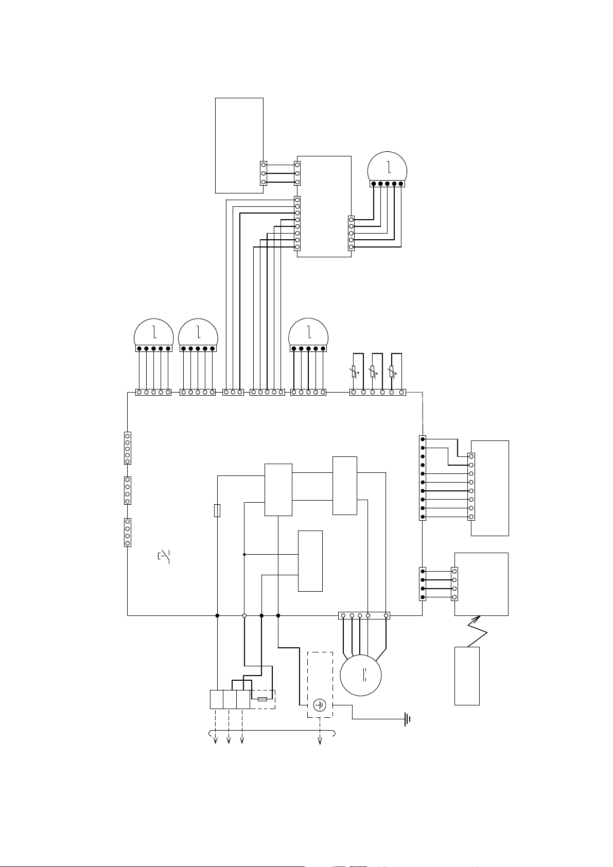
8.2 Outdoor Unit
Resistance of Compressor Windings
MODEL CU-XE9/12SK
CONNECTION 5RS102XHB21 (Ω)
U-V 1.741
U-W 1.765
V-W 1.711
Note: Resistance at 68°F (20°C) of ambient temperature.
YELLOW(YLW)
BLUE
(BLU)
RED
(RED)
(TRADEM A RK)
COMP. TERMINAL
THE PARENTHESIZED L ETTERS IS
INDICATED ON TERMINAL COVER
TERMINAL
BOARD
RECTIFICATION
CIRCUIT
SWITCHING POWER
SUPPLY CIRCUIT
(RED) U
BLU
YLW
(BLUE) V
(YELLOW) W
RED
RECTIFICATION
CIRCUIT
SINGLE PHASE
POWER SUPPLY
FUSE3
(20A,
250V)
AC-BLK
(BLACK)
AC-WHT
(WHITE)
t
tt
CN-TA NK
(WHITE)
CN-TH1
(WHITE)
L1 L2
3
(RED)
(BLK) (WHT)(RED)
2
(WHT)
1
(BLK)
TO IN
D
OO
R
U
NIT
YLW/GRN
MS
3
〜
GRN
CABINET
SIDE
PLATE
ELECTRONIC CONTROLLER
COMMUNICATION
CIRCUIT
NOISE
FILTER
CIRCUIT
FG01
(GREEN)
CN-EV
(WHITE)
COM3
(RED)
FUSE2
(T 3.15A L 250V)
M
RED
BLU
YLW
RED
BLK
GROUNDING TERMINAL
WHT
WHT
BLK
13
CN-HOT
(BLUE)
BLU
FUSE1
(T 2.5A L250V)
1
3
1
WHT
WHT
3
1
3
PFC
CIRCUIT
GRYGRY
REACTOR
RED
P
N
V
W
U
YLW
BLU
WHT
M
1
11
33
7
CN-DCFM
(WHITE)
FAN MOTOR
ELECTRO-MAGNETIC CO IL
(EXPANSION
VALVE)
COMP. TEMP.
SENSOR (THERMISTOR)
PIPING TEMP.
SENSOR
(THERMISTOR)
OUTDOOR AIR
TEMP. SENSOR
(THERMISTOR)
31 14
REMARKS
BLU:BLUE GRY:GRAY
BRW:BROWN GRN:GREEN
BLK:BLACK RED:RED
WHT:WHITE YLW:YELLOW
YLW/GRN:YELLOW/GREEN
6
1
L2-0
(GRAY)
L2-I
(GRAY)
Q10
COMPRESSOR
ELECTRO-MAGNETIC COIL
(4-WA Y V A L V E )
HEATER
BLK
RY-HT1
CN-HT1
(WHITE)
RY-HOT
Y
L
W/G
R
N
19
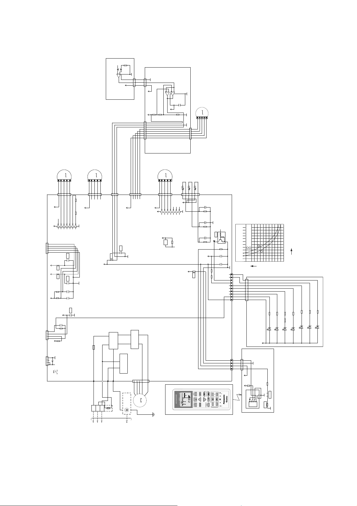
9. Electronic Circuit Diagram
9.1 Indoor Unit
70
60
50
Resistance (kΩ)
Sensor (Thermistor)
Characteristics
40
30
20
10
0
Pipe Temp. Sensor
Intake Air Temp. Sensor
1
1
2
2
AUTO SW
(SW01)
YLW/GRN
RED
GROUNDING
TERMINAL
3
GRN
WHT
TEMP.FUSE
215.6˚F/102˚C (3A)
TERMINAL
BOARD
2
EVAPORATOR
T
OO
U
T
D
OO
R
U
N
I
T
1
G301(GRN)
AC304(RED)
AC303(WHT)
FUSE301
T3.15A L250V
NOISE FILTER
CIRCUIT
COMMUNICATION
CIRCUIT
RECTIFICATION
CIRCUIT
UP DOWN
LOUVER MOTOR
(OUTER)
M
PIPING TEMP. SENSOR 2
(THERMISTOR) (20k 3950)
BRW
1
5
ORG
PNK
RED
5
YLW
1
4
CN-FM
(WHT)
7
1
M
BLK
RED
WHT
BLU
YLW
FAN MOTOR
14
CN-RMT
(WHT)
14
CN-CLN
(GRN)
CN-CNT
(WHT)
12345
CN-STM1
(WHT)
LEFT RIGHT
LOUVER MOTOR
M
BRW
1
5
ORG
PNK
RED
5
YLW
1
CN-STM2
(YLW)
1
CN-MSENS
(WHT)
1
CN-STM3
(GRN)
5
3
LOUVER MOTOR
UP DOWN
(INNER)
CN-STM4
(BLU)
SUCTION TEMP.
SENSOR (THERMISTOR) (15k 3950)
t
PIPING TEMP. SENSOR 1
(THERMISTOR) (20k 3950)
CN-TH
(RED)
1
CN-DISP(YLW)
10
1
6
CN-RCV
(YLW)
14
1
CN-DISP(WHT)
8
ELECTRONIC CONTROLLER
(DISPLAY)
1
4
CN-RCV
(WHT)
ELECTRONIC
CONTROLLER
(RECEIVER)
ELECTRONIC
CONTROLLER
(MAIN)
WHT
BLK AC306(BLK)
WHT
WHT
WHT
1
M
BRW
ORG
YLW
5
PNK
5
RED
1
WHT
WHT
WHT
WHT
M
1
1
3
CN-SENS
(GREEN)
CN-STM
(GREEN)
3
CN-SENS
(WHT)
CN-MSSTM
(WHT)
5
ELECTRONIC CONTROLLER
(ECO SENSOR)
1
1
8
ELECTRONIC
ECO SENSOR
MOTOR
CONTROLLER
(COMPARATOR)
51
t
t
WHT
WHT
WHT
YLW
RED
ORG
BRW
PNK
WHT
WHT
WHT
WHT
WHT
WHT
WHT
WHT
WHT
WHT
WHT
WHT
REMOTE CONTROLLER
12V
12V
1
2
3
4
5
6
7
16
9
8
15
14
13
12
11
10
IC03
R47 1/2W
68
R46 1/2W
68
GND
VCC
C25
1µ
16V
R62
15.0k
1%
C27
1µ
16V
R61
20.0k
1%
C28
1µ
16V
R63
20.0k
1%
5V
C52
1000p
50V
*C57
*C56
*L5
5V 5V
*L6
12V
C51
1000p
50V
R90
10k
R82
10k
R403
13.0k
1%
C403
0.1µ
25V
R402
10.0k
1%
R401
27.0k
1%
6
5
2
8
4
7
1
3
GND
IC401
VCC
5V_3
G2
5V_3
5V_3
G2
G2
G2
C407
0.1µ
25V
6
5
7
IC402
5V_6
G2
R408
62.0k
1%
*R213
1
2
3
Vout
Vcc
GND
GND GND
54
IC201
GND-A
R209
47
5V_
5V_
GND-A
GND-A
*R214
1.0k
1%
*JP204
GND
VCC
12V
1
2
3
4
5
6
7
16
9
8
15
14
13
12
11
10
IC06
G2
*C40
*R74
5V
R58
1M
1%
4.7k
10k
C3
0.1µ
16V
C1
0.1µ
16V
12V
c
e
b
*Q09
5V
*R89
186
R91 R92
C45
0.01µ
*C49
R54
270
R37
10k
5V
5V
12V
12V
POWER
(green)
LED301
TIMER
(orange)
ECONAVI
(green)
QUIET
(orange)
RFP
(green)
POWERFUL
(orange)
AUTO COMF
(green)
LED304
R301
R304
R310R302
R303
R305
LED302
LED303
LED305
LED307
LED306
R306
680
R307
5V_
Temperature °F (°C)
14
(-10)
32
(0)
50
(10)
68
(20)
86
(30)
104
(40)
122
(50)
CLOCK
AIR CONDI TIONER
OFF/ON
SET CHE CK RESE T
AC
RC
ON
OFF
SET
123
TIMER
AUTO
COMFOR T
POWERFUL/
QUIET
MODE
TEMP
FAN SPEED
AIRSWING
ECONAVI
RFP
MODE
O
FF/
O
N
C
HE
C
K
O
N
O
FF
S
ET
1
2
3
T
I
M
E
R
TEMP
CANCEL
12V
D4
5V
R30
BZ1
BZ
20
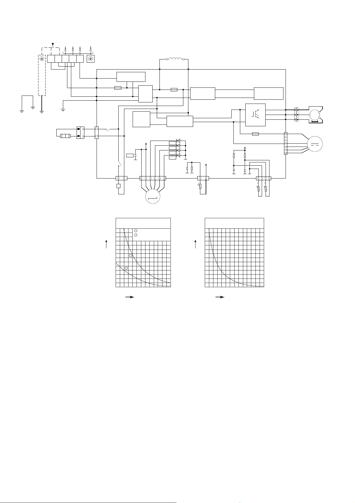
9.2 Outdoor Unit
Sensor (Thermistor)
Characteristics
70
60
50
40
30
20
10
0
Resistance (kΩ)
1
2
1
2
Outdoor Air Sensor
Outdoor Heat Exchanger
Sensor
Compressor Temp. Sensor
(Thermistor) Characteristics
70
60
50
40
30
20
10
0
Resistance (kΩ)
RECTIFICATION
CIRCUIT
SWITCHING POWER
SUPPLY CIRCUIT
(RED) U
BLU
YLW
(BLUE) V
(YELLOW) W
RED
RECTIFICATION
CIRCUIT
FUSE3
(20A,
250V)
AC-BLK
(BLACK)
AC-WHT
(WHIT E )
t
tt
CN-TANK
(WHITE)
CN-TH1
(WHITE)
MS
3
〜
ELECTRONIC CONTROLLER
COMMUNICATION
CIRCUIT
NOISE
FILTER
CIRCUIT
FG01
(GREEN)
CN-EV
(WHITE)
COM3
(RED)
FUSE2
(T 3.15A L 250V)
M
RED
BLU
YLW
13
CN-HOT
(BLUE)
BLU
FUSE1
(T 2.5A L250V)
1
3
PFC
CIRCUIT
GRYGRY
REACTOR
RED
P
N
V
W
U
YLW
BLU
WHT
M
1
11
33
7
CN-DCFM
(WHITE)
FAN M OTOR
ELECTRO-MAGNETIC COIL
(EXPANSION
VALVE)
COMP. TEMP.
SENSOR (THERMISTOR)
(50k, 3950)
PIPING TEMP.
SENSOR
(THERMISTOR)
(4.96k, 3800)
OUTDOOR AIR
TEMP. SENSOR
(THERMISTOR)
(15k, 3950)
31 14
6
1
L2-0
(GRAY)
L2-I
(GRAY)
Q10
COMPRESSOR
ELECTRO-MAGNETIC COIL
(4-WAY VALVE)
BLK
RY-HT1
CN-HT1
(WHITE)
RY-HOT
Temperature °F (°C)
14
(-10)
32
(0)
50
(10)
68
(20)
86
(30)
104
(40)
122
(50)
68
(20)
104
(40)
140
(60)
176
(80)
212
(100)
248
(120)
284
(140)
Te
m
pe
r
at
u
r
e°
F
(
°
C
)
5V
R100
15.0k
1%
R101
15.8k
1%
C45
1µ
6.3V
C46
1µ
6.3V
5V
R410
4.99k
C49
1µ
10V
*D33
*D34
*D35
*D36
G1
G1
*C84
13V
G1 G1 G1
G1 G1
TERMINAL
BOARD
SINGLE PHASE
POWER SUPPLY
L1 L2
3
(RED)
(BLK) (WHT)(RED)
2
(WHT)
1
(BLK)
T
O
I
N
D
O
O
R
U
N
I
T
YLW/GRN
GRN
CABINET
SIDE
PLATE
RED
BLK
GROUNDING TERMINAL
WHT
WHT
BLK
1
WHT
WHT
3
1
3
HEATER
Y
L
W/
G
R
N
21
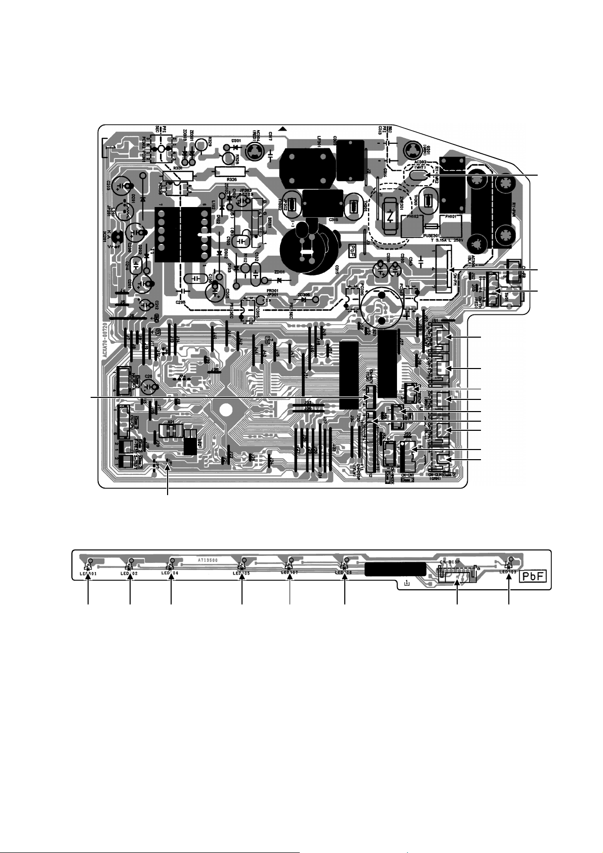
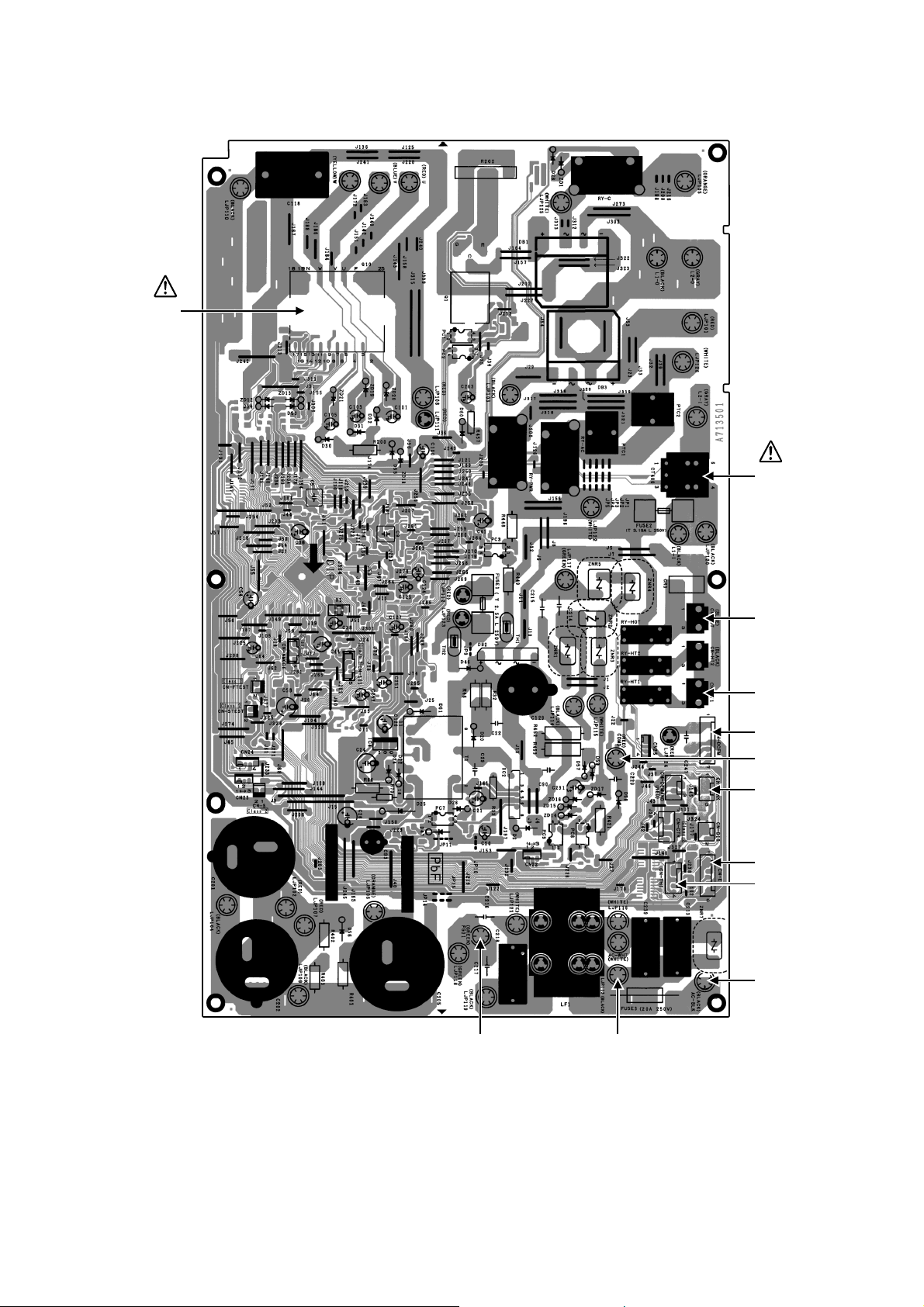
10. Printed Circuit Board
10.1 Indoor Unit
10.1.1 Main Printed Circuit Board
10.1.2 Indicator Printed Circuit Board
AC303
CN-STM2
CN-STM1
CN-STM3
CN-MSENS
CN-STM4
CN-RCV
CN-DISP
CN-RMT
JP1 (Random Auto Restart enable/disable)
CN-CNT
CN-CLN
CN-TH
CN-FM
LED301 LED302 LED304 LED305 LED307 LED306 LED303CN-DISP
22
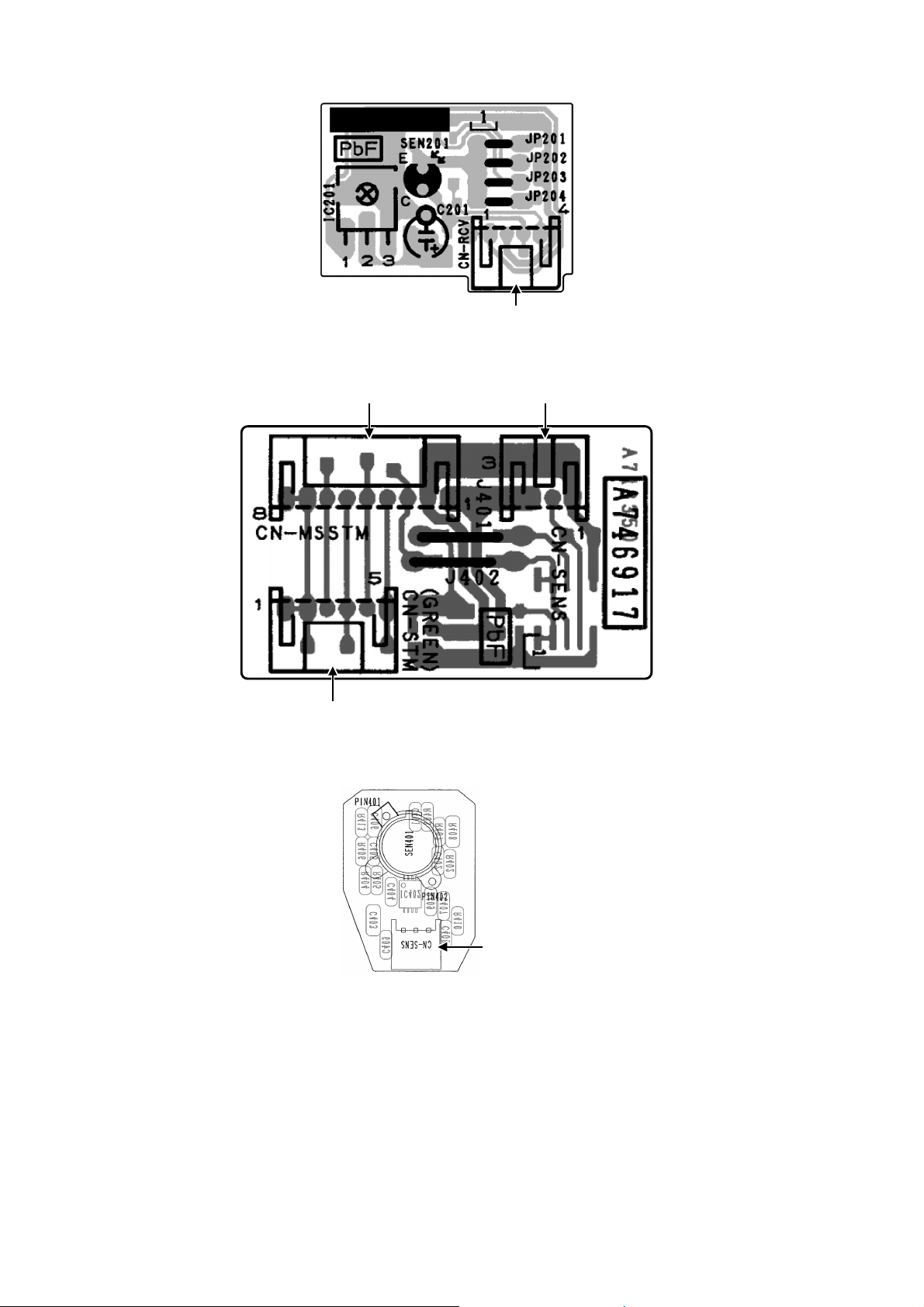
10.1.3 Receiver Printed Circuit Board
10.1.4 Comparator Printed Circuit Board
10.1.5 Human Activity Sensor Printed Circuit Board
CN-RCV
CN-STM
CN-
M
SST
M
CN-SENS
CN-SENS
23
10.2 Outdoor Unit
10.2.1 Main Printed Circuit Board
CN-HOT
CN-HT1
CN-TH1
AC-BLK
CN-EV
CN-TANK
COM3
CN-DCFM
CURRENT
TRANSFORMER
(CT)
POWER
TRANSISTOR
(IPM)
AC-WHTFG01
24
11. Installation Instruction
11.1 Select the Best Location
11.1.1 Indoor Unit
Do not install the unit in excessive oil fume area
such as kitchen, workshop and etc.
There should not be any heat source or steam
near the unit.
There should not be any obstacles blocking the air
circulation.
A place where air circulation in the room is good.
A place where drainage can be easily done.
A place where noise prevention is taken into
consideration.
Do not install the unit near the door way.
Ensure the spaces indicated by arrows from the
wall, ceiling, fence or other obstacles.
Mount with the lowest moving parts at least 8ft
(2.4 m) above floor or grade level.
11.1.2 Outdoor Unit
If an awning is built over the unit to prevent direct
sunlight or rain, be careful that heat radiation from
the condenser is not obstructed.
There should not be any animal or plant which
could be affected by hot air discharged.
Keep the spaces indicated by arrows from wall,
ceiling, fence or other obstacles.
Do not place any obstacles which may cause a
short circuit of the discharged air.
If piping length is over the [piping length for
additional gas], additional refrigerant should be
added as shown in the table.
Recommended installation height for outdoor unit
should be above the seasonal snow level.
Be careful not to locate outdoor unit directly under
a roof line where falling snow or ice can cause
damage or dripping water can increase ice
accumulation and defrost cycles.
Example: For XE9SKUA
If the unit is installed at 32.8 ft (10 m) distance, the
quantity of additional refrigerant should be 1.64 oz
(50 g) .... (32.8 - 24.6) ft x 0.2 oz/ft = 1.64 oz.
((10-7.5) m x 20 g/m = 50 g)
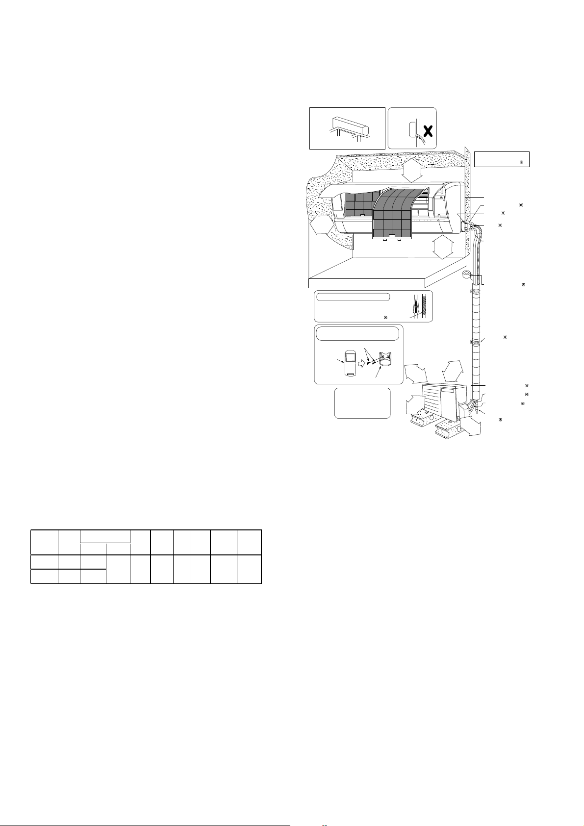
11.1.3 Indoor/Outdoor Unit Installation
Diagram
Model
Capacity
(Btu/h)
Piping size
Std.
Length
Max.
Elevation
Min.
Piping
Length
Max.
Piping
Length
Additional
Refrigerant
Piping
Length for
add. g as
Gas Liquid
XE9SKUA
8700
3/8"
(9.52 m m )
1/4"
(6.35 m m )
24.6 ft
(7.5 m)
49.2 ft
(15 m)
9.8 ft
(3 m)
65.6 ft
(20 m)
0.2 oz/ft
(20 g/m)
24.6 ft
(7.5 m)
XE12SKUA
11500
1/2"
(12.7 m m )
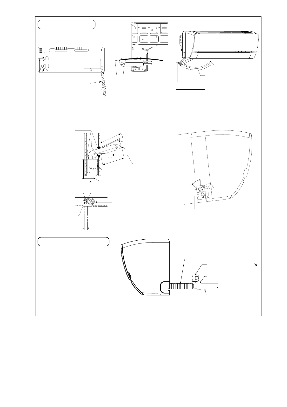
Piping direction Do not bend up
drain hose
(Front side)
Right
Rear
Right
bottom
Left
Rear
Left bottom
Left
(Left and right are identical)
Vinyl tape
6
Remote control holder
5
Remote
control
3
• This illustration is for
explanation purposes only .
The indoor unit will actually face
a different way.
It is advisable to avoid m ore
than 2 blockage directions.
For better ventilation &
multiple-outdoor installation,
please consult authorized
dealer/specialist.
Installation plate 1
Sleeve (
)
Bushing-Sleeve (
)
Bend the pipe as
closely on the wall
as possible, but be
careful that it doesn’t
break.
Saddle (
)
Additional drain
hose (
)
Gas side piping (
)
Connection cable (
)
Putty (
)
(Gum Type Sealer)
Installation parts you
should purchase (
)
Vinyl tape (wide) ( )
• Apply after carrying
out a drainage test.
• To carry out the
drainage test,
and pour water into
remove the air filter
s
the heat exchanger.
Liquid side piping (
)
• Carry out insulation after
checking for gas leaks and
secure with vinyl tape.
Remote control holder fixing screws
Attaching the remote control holder
to the wall
Insulation of piping connections
Floor / Grade level
2
9
/
1
6
"
(
6
5
m
m
)
o
r
m
o
r
e
1
31
/
32
"
(50 mm)
or more
3
1
5
/
1
6
"
(
1
0
0
m
m
)
o
r
m
o
r
e
3
9
3
/
8
"
(
1
0
0
0
m
m
)
o
r
m
o
r
e
3
1
5
/
1
6
"
(
1
0
0
m
m
)
o
r
m
o
r
e
1
1
1
3
/
1
6
"
(
3
0
0
m
m
)
o
r
m
o
r
e
8ft(2.4m)
or more
25
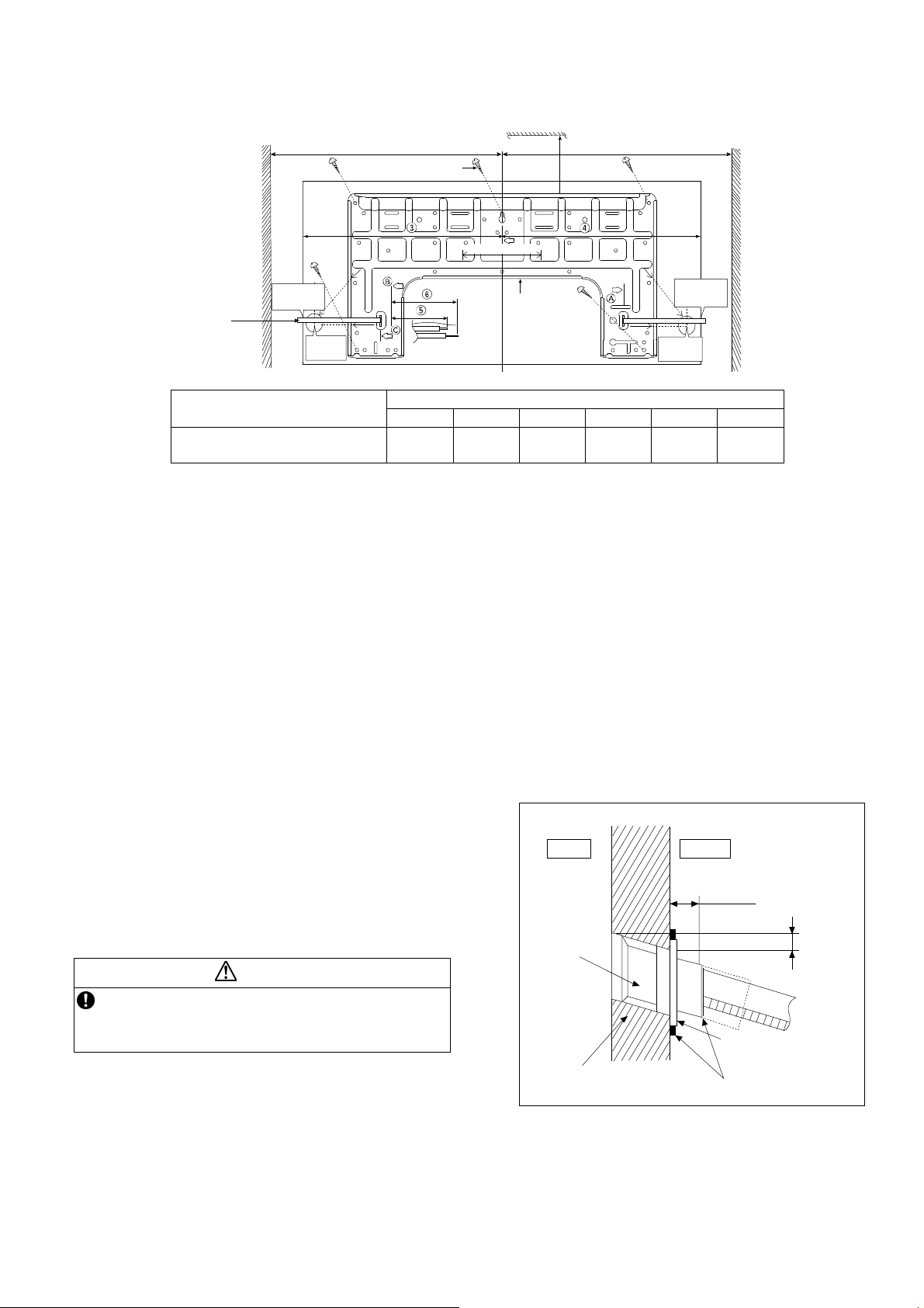
11.2 Indoor Unit
The mounting wall shall be strong and solid enough to prevent it from vibration.
Model
Dimension
1 2 3 4 5 6
XE9SKUA, XE12SKUA
19-9/32"
(490 mm)
3-7/32"
(82 mm)
17-9/32"
(439 mm)
17"
(432 mm)
1-11/16"
(43 mm)
3-3/4"
(95 mm)
The center of installation plate should be at more than 1 at right and left of the wall.
The distance from installation plate edge to ceiling should more than 2.
From installation plate left edge to unit’s left side is 3.
From installation plate right edge to unit’s right is 4.
○
B : For left side piping, piping connection for liquid should be about 5 from this line.
: For left side piping, piping connection for gas should be about 6 from this line.
1 Mount the installation plate on the wall with 5 screws or more (at least 5 screws).
(If mounting the unit on the concrete wall, consider using anchor bolts.)
o Always mount the installation plate horizontally by aligning the marking-off line with the thread and using
a level gauge.
2 Drill the piping plate hole with ø2-3/4" (ø70 mm) hole-core drill.
o Line according to the left and right side of the installation plate. The meeting point of the extended line is
the center of the hole. Another method is by putting measuring tape at position as shown in the diagram
above. The hole center is obtained by measuring the distance namely 5-1/16" (128 mm) for left and right
hole respectively.
o Drill the piping hole at either the right or the left and the hole should be slightly slanting to the outdoor
side.
11.2.1 To Drill a Hole in the Wall and
Install a Sleeve of Piping
1 Insert the piping sleeve to the hole.
2 Fix the bushing to the sleeve.
3 Cut the sleeve until it extrudes about 19/32"
(15 mm) from the wall.
CAUTION
When the wall is hollow, please be sure to use the
sleeve for tube assembly to prevent dangers
caused by mice biting the connection cable.
4 Finish by sealing the sleeve with putty or
caulking compound at the final stage.
DISTANCE
TO PIPE
HOLE
CENTER
128 mm
DISTANCE TO
PIPE HOLE
CENTER 128 mm
PIPE HOLE CENTER
PIPE HOLE
CENTER
Wall
Wall
Wall
Insta llatio n
plate 1
2 screw
More than 1
More than 1
Measuring
Tape
9
17
/
32
"
(241.5 m m )
9
17
/
32
"
(241.5 mm)
5
1
/
16
"
(128 mm)
More
than 2
5
1
/
16
" (128 mm)
5
1
/
16
"
(128 mm)
Putty or caulking compound
Indoor
Outdoor
Sleeve
for tube
assembly
Bushing for tube
assembly
Wall
19
/
32
"(15mm)
ø2
3
/
4
" (ø70 mm)
through hole
Approx.
7
/
32
"-
9
/
32
"
(5-7 m m)
26
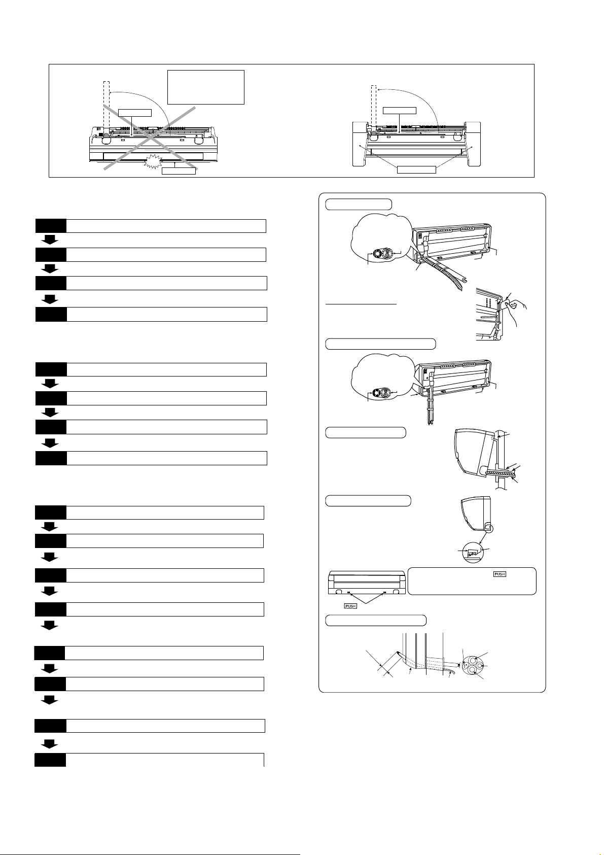
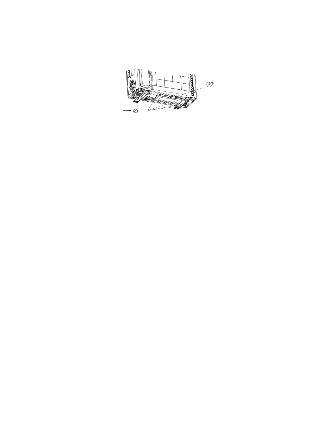
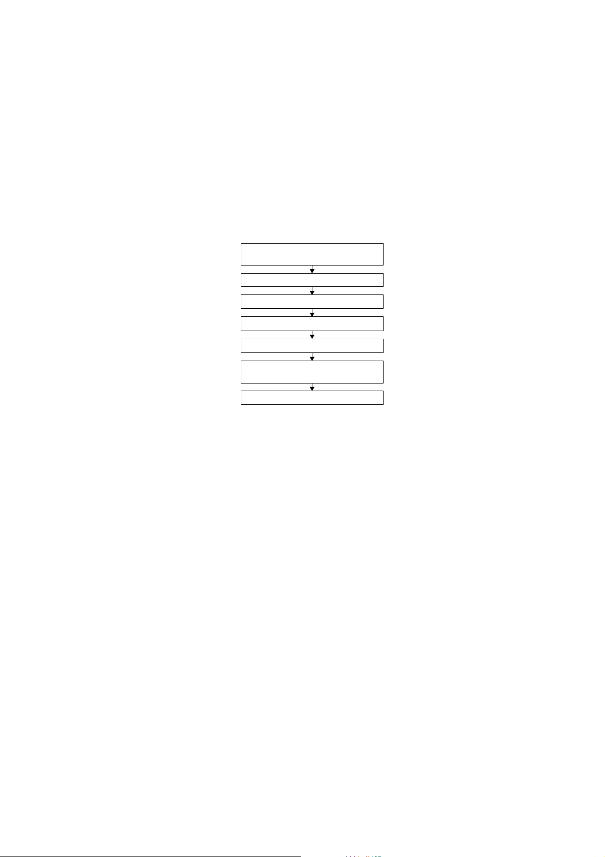
11.2.2 Indoor Unit Installation
11.2.2.1 For the right rear piping
11.2.2.2 For the right bottom piping
11.2.2.3 For the embedded piping
(This can be used for left rear piping and bottom
piping also.)
PUSH PUSH
PUSH PUSH
Piping
Piping
Shock absorber
Intake grille
p
u
l
l
o
u
t
t
h
e
p
i
p
i
n
g
p
u
l
l
o
u
t
t
h
e
p
i
p
i
n
g
Do not turn over the unit
without it’s shock absorber
during pulling out the piping.
It may cause intake grille
damage.
Use shock absorber
during pulling out
the piping to protect
the intake grille from
damage.
Install the Indoor Unit
Pull out the Indoor piping
Step-2
Step-1
Secure the Indoor Unit
Insert the connection cable
Step-3
Step-4
Install the Indoor Unit
Pull out the Indoor piping
Step-2
Step-1
Insert the connection cable
Secure the Indoor Unit
Step-3
Step-4
• Use a spring bender or equivalent to bend the piping so that the
piping is not crushed.
• When determining the dimensions of the piping, slide the unit all the
•
way to the left on the installation plate.
• Refer to the section “Cutting and flaring the piping”.
Bend the embedded piping
Replace the drain hose
• The inside and outside connection cable can be connected without
remo vin g the front grille.
• Please refer to “Connecting the piping” column in outdoor unit
section. (Below steps are done after connecting the outdoor piping
and gas-leakage confirmation.)
Connect the piping
• Please refer t o “Insulation of piping connection” column as
mentioned in indoor/outdoor unit installation.
Install the Indoor Unit
Secure the Indoor Unit
Insulate and finish the piping
Step-1
Pull the connection cable into Indoor Unit
Step-3
Cut and flare the embedded piping
Step-4
Step-2
Step-5
Step-6
Step-7
Step-8
Install the indoor unit
Right Rea r piping
Hook the indoor unit on to the upp er portion
of installation plate. (Enga ge the indoor u nit
with the upper edge of the installation plate).
Ensure the hoo ks are properly seated on
the installation plate by moving it in left and
right.
Cover for the
bottom piping
Cover for the
botto m p ip in g
Tape it w ith
piping in a position as
mentioned in
Fig. below.
Piping
Drain
hose
Cover
for the
left
piping
1. Press the lower left and right side of the
unit against the installation plate until hooks
engages with their slot (sound click).
Cover for piping
In case the cover is cut, keep the cover at the rear
of chassis as shown in the illustration for future
reinstallation.
(Left and 2 bottom covers for piping.)
How to keep the cover
Right and Right Bo ttom piping
Insert the connection cable
Secure the Indoor Unit
To take ou t the unit, push the marking
at the bottom u nit, and pull it slightly towards
you to disengage the hooks from the unit.
g
n
i
k
r
a
m
Drain hose
Sleeve for
piping hole
Indoor unit
Hooks at
installa tio n
plate
Piping
Insta lla tion
plate
Unit’s
hook
Cover for the
bottom piping
Tape it with piping in a
position as mentioned in
Fig. below.
Cover for
the right
piping
Piping
Drain hose
Cover for
the left
piping
Guide
surface
Connection cable
Connection
cable
Gas side
piping
Liquid side
piping
Drain hose
A
b
o
u
t
2
3
/
4
"
-
3
5
/
3
2
"
(
7
0
-
8
0
m
m
)
27
Rear view for left piping installation
Drain cap
Drain hose
Adjust the piping
slightly downwards.
•
How to insert the connection cable
and drain hose in the case of left
piping.
(F or right piping, follow the same
procedure)
Replace the drain hose
Drain hose
Connection cable
Sleeve for piping hole
Drain hose
Piping
Connection cable
Cable
4
5
°
Drain
hose
Piping
More than 45
9
/
32
"
(1150 mm)
•
How to pull the piping and drain hose out, in case
of embedded piping
.
PVC tube
for drain
hose
Indoor unit
Piping
Cable
Apply putty or
caulking material
to seal the wall
opening.
Connection
cable
Piping
PVC tube (VP-65) for piping
and connection cable
PVC tube for drain hose (VP-30)
PVC tube for drain
hose (VP-20)
Drain hose
from main unit
2
27
/
32
"(72mm)
M
o
r
e
t
h
a
n
1
8
1
/
2
"
(
4
7
0
m
m
)
M
o
re
t
h
a
n
4
5
9
/
3
2
"
(1
1
5
0
m
m
)
More than
27
9
/
16
"
(700 mm)
Indoor unit
drain hose
3/4" (20 mm) nominal PVC pipe
- Install incline downward more than 1°
- Apply PVC glue at the join.
Drain hose adapter
7
Close join by Vinyl Tape ( )
•
Join indoor drain hose to 3/4"
(20 mm) nominal PVC pipe size
by using drain hose adapter
7
when necessary.
Drain hose adapter
7
usage
Remarks :
Make sure indoor unit drain hose
& 3/4" (20 mm) nominal PVC pipe
are fully inserted to drain hose
adapter
7
.
28
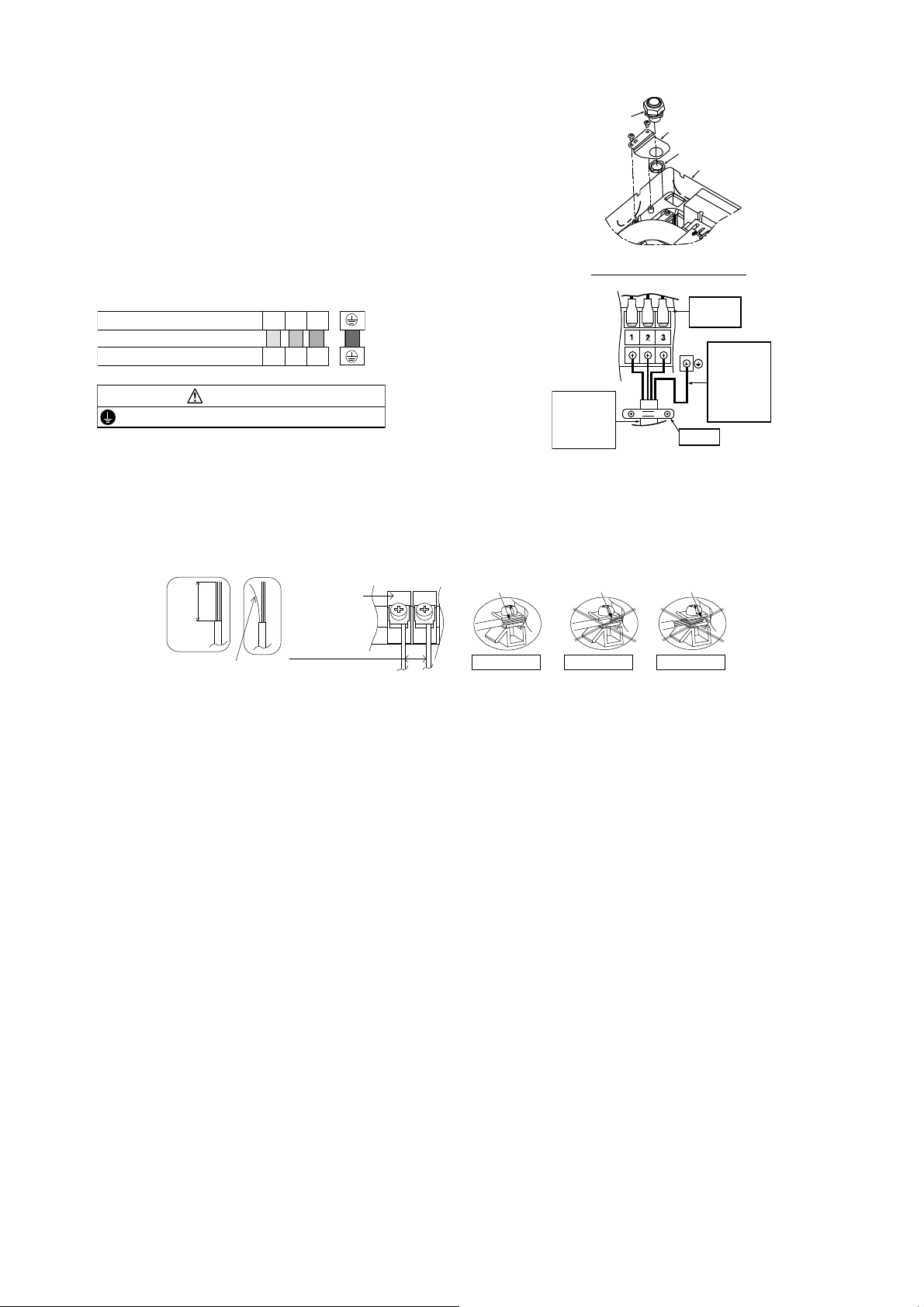
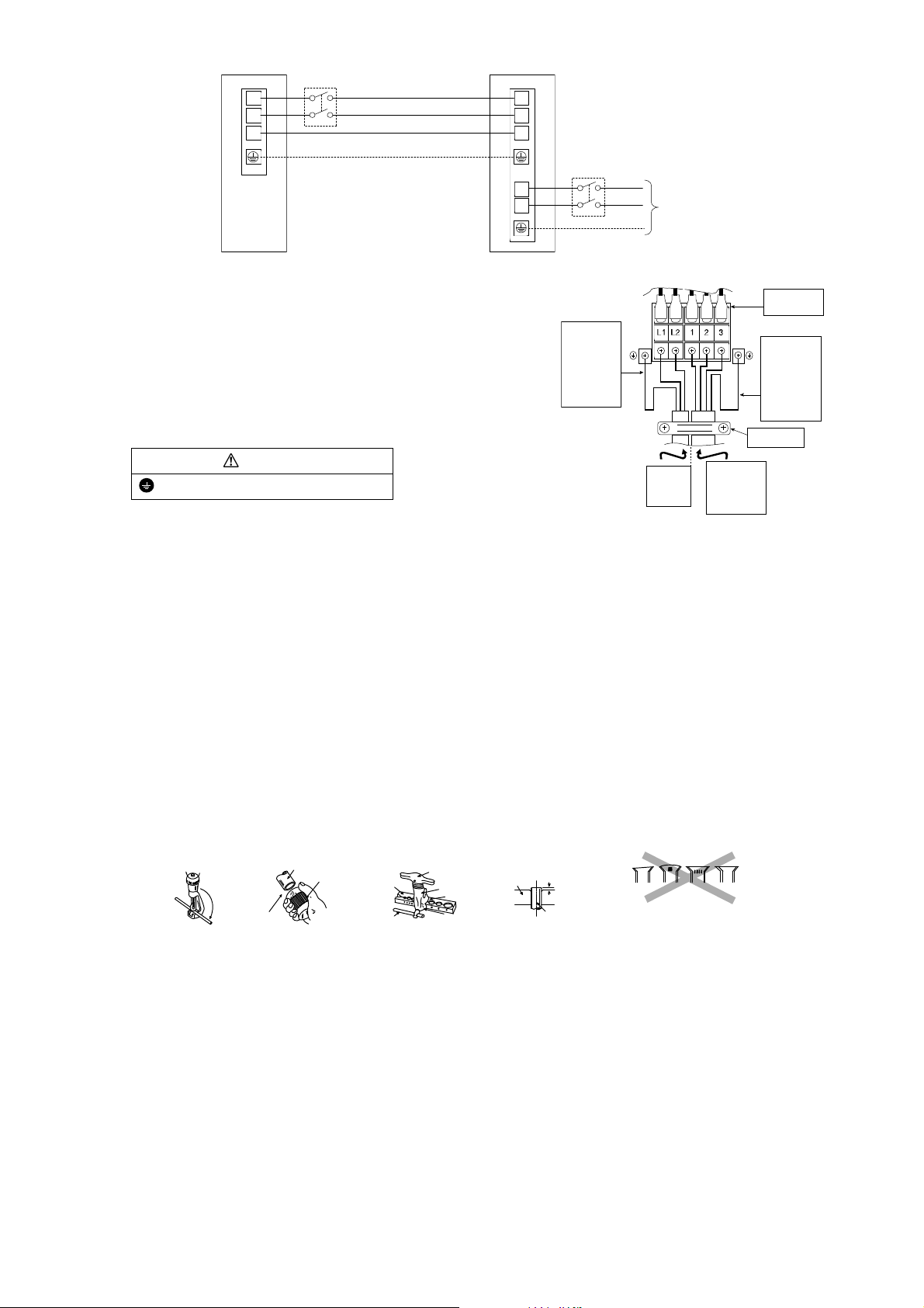
11.2.3 Connect the Cable to the Indoor Unit
1 The inside and outside connection cable can
be connected without removing the front grille.
2 Unscrew the conduit cover and fix the conduit
connector to conduit cover with lock nut, then
secure it against chassis.
3 Connection cable between indoor unit and
outdoor unit should be UL listed or CSA
approved 4 conductor wires minimum AWG16
in accordance with local electric codes.
o Ensure the colour of wires of outdoor unit
and terminal number are the same as the
indoor's respectively.
o Earth lead wire shall be Yellow/Green
(Y/G) in colour and shall be longer than
other lead wires as shown in the figure
for electrical safety in case of slipping.
11.2.3.1 Wire Stripping and Connecting Requirement
Terminals on the indoor unit 1 2 3
Colour of wires (connection cable)
Terminals on the outdoor unit 1 2 3
WARNING
This equipment must be properly earthed.
Holder
Chassis
Conduit
Connector
Conduit Cover
Lock Nut
Rear Side of Indoor Unit
Indoor and
outdoor
connection
cable
Terminal
Board
Earth wire
longer than
others
AC wires
for safety
reason
Wi
r
e
s
t
r
i
p
p
i
n
g
7
/
32
" (5 mm)
or more
(gap between wires)
ACCEPT
PROHIBITED
Conductor
over inserted
No loose strand
when inserted
Indoor/outdoor
connecting
terminal board
Conductor
fully inserted
PROHIBITED
Conductor not
fully inserted
13/32" ± 1/16"
(10 ± 1 mm)
29
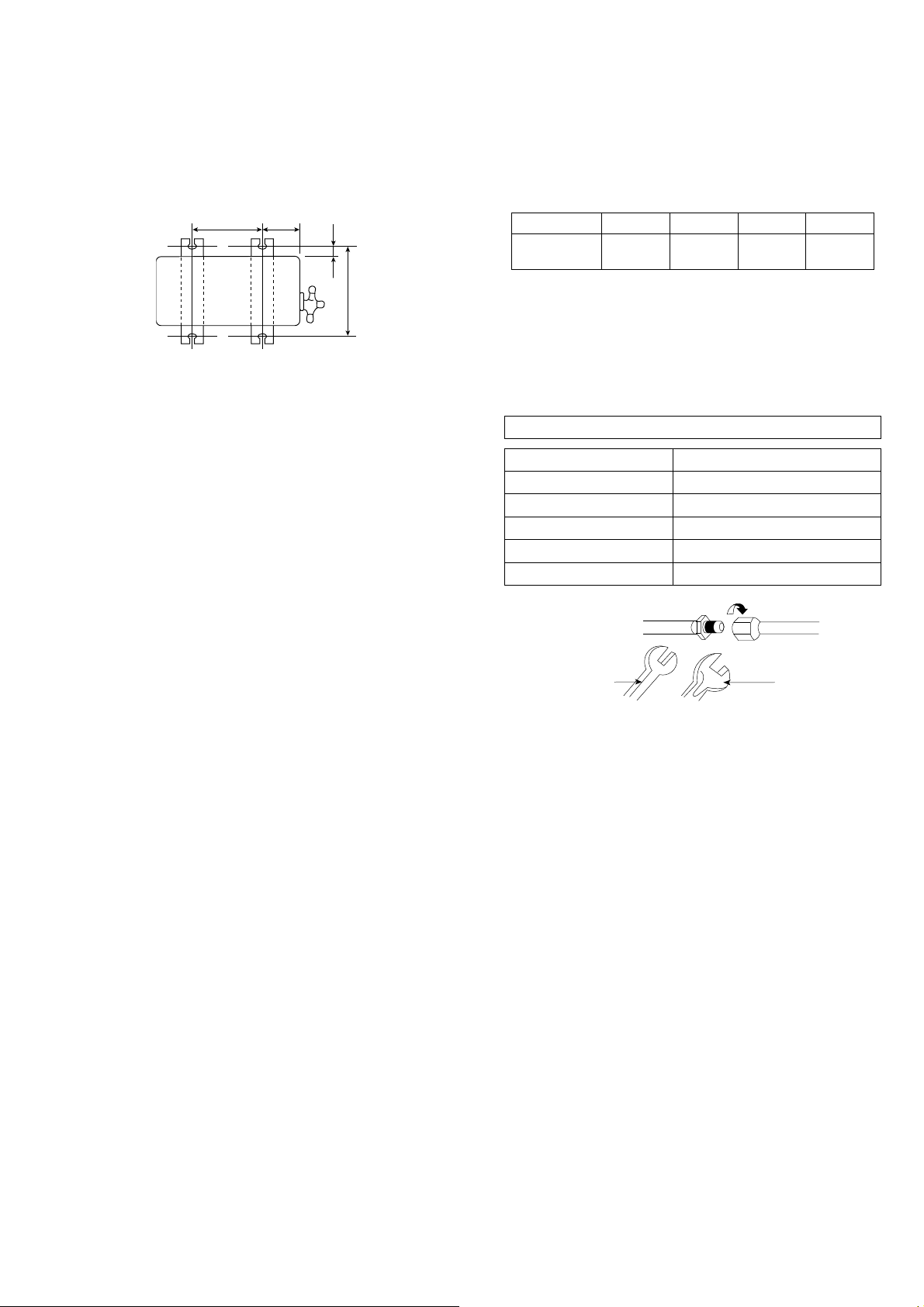
11.3 Outdoor Unit
11.3.1 Install the Outdoor Unit
After selecting the best location, start installation according to Indoor/Outdoor Unit Installation Diagram.
1 Fix the unit on concrete or rigid frame firmly and horizontally with a bolt nut ø13/32" (ø10 mm).
2 When installing at roof, please consider strong wind and earthquake.
Please fasten the installation stand firmly with bolt or nails.
Model A B C D
XE9SKUA,
XE12SKUA
24-1/8"
(613 mm)
5-5/32"
(131 mm)
5/8"
(16 mm)
14-3/16"
(360.5 mm)
11.3.2 Connect the Piping
11.3.2.1 Connecting the Piping to
Indoor
Please make flare after inserting flare nut (locate at
joint portion, of tube assembly) onto the copper pipe.
(In case of using long piping)
Connect the piping
Align the center of piping and sufficiently tighten
the flare nut with fingers.
Further tighten the flare nut with torque wrench in
specified torque as stated in the table.
11.3.2.2 Connecting the Piping to
Outdoor
Decide piping length and then cut by using pipe cutter.
Remove burrs from cut edge.
Make flare after inserting the flare nut (located at valve)
onto the copper pipe.
Align center of piping to valve and then tighten with
torque wrench to the specified torque as stated in the
table.
11.3.2.3 Gas leak checking
Pressure test to system to 400 PSIG with dry nitrogen, in stages. Thoroughly leak check the system.
If the pressure holds, release the nitrogen and proceed to section 11.3.3.
A
B
C
D
Torque
wrench
S
panner
or Wrench
Do not over tighten, over tightening may cause gas leakage
Piping size Torque
1/4" (6.35 mm) 13.3 Ibf.ft [18N•m (1.8 kgf.m)]
3/8" (9.52 mm) 31.0 Ibf.ft [42 N•m (4.3 kgf.m)]
1/2" (12.7 mm) 40.6 Ibf.ft [55 N•m (5.6 kgf.m)]
5/8" (15.88 mm) 47.9 Ibf.ft [65 N•m (6.6 kgf.m)]
3/4" (19.05 mm) 73.8 Ibf.ft [100 N•m (10.2 kgf.m)]
30
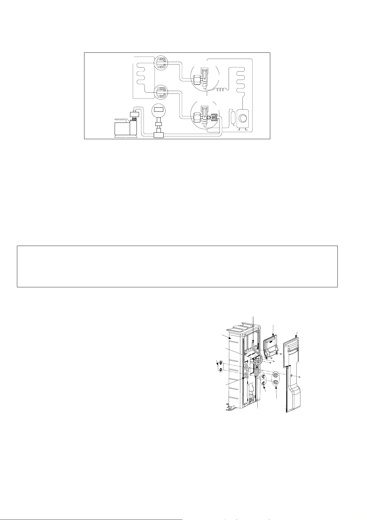
11.3.3 Evacuation of the Equipment
WHEN INSTALLING AN AIR CONDITIONER, BE SURE TO EVACUATE THE AIR INSIDE THE INDOOR UNIT AND
PIPES in the following procedure.
1 Connect a charging hose with a push pin to the Low side of a charging set and the service port of the 3-way
valve.
2 Connect the micron gauge between vacuum pump and service port of outdoor units.
3 Turn on the power switch of the vacuum pump and make sure that connect digital micron gauge and to pull
down to a value of 500 microns.
4 To make sure micron gauge a value 500 microns and close the low side valve of the charging set and turn off
the vacuum pump.
5 Disconnect the vacuum pump house from the service port of the 3-way valve.
6 Tighten the service port caps of the 3-way valve at a torque of 13.3 Ibf.ft (18 N•m) with a torque wrench.
7 Remove the valve caps of both of the 2-way valve and 3-way valve. Position both of the valves to “Open”
using a hexagonal wrench (5/32" (4 mm)).
8 Mount valve caps onto the 2-way valve and the 3-way valve.
o Be sure to check for gas leakage.
If micron gauge value does not descend 500 microns, take the following measures:
- If the leak stops when the piping connections are tightened further, continue working from step .
- If the leak does not stop when the connections are retightened, repair location of leak.
- Do not release refrigerant during piping work for installation and reinstallation.
- Be careful with the liquid refrigerant, it may cause frostbite.
11.3.4 Connect the Cable to the Outdoor Unit
1 Remove control board cover (Resin and
Metal).
2 Remove particular plate.
3 Remove plugs.
4 Fix the conduit connectors to the knockout
holes with lock-nuts, then secure them against
the side panel.
5 All wires pass through conduits & particular
plate’s opening hole.
6 Connecting wire between indoor unit and
outdoor unit should be UL listed or CSA
approved 4 conductor wires minimum AWG16
in accordance with local electric codes.
7 Wire connection to the power supply
(208/230V 60Hz) through circuit breaker.
o Connect the UL listed or CSA approved
wires minimum AWG14 to the terminal
board, and connect the other end of the
wires to ELCB/ GFCI.
8 Connect the power supply cord and
connecting wire between indoor unit and
outdoor unit according to the diagram below.
Gas side
Liquid side
Outdoor unit
Tw o - w ay valve
Three-way valve
Indoor unit
Vacuum
pump
Close
Close
Control Board
Cover (Metal)
L
ock Nuts
Knockout
Holes
Front
Panel
Conn
e
c
ting wi
r
e
s
Control Board
Cover (Resin)
Connectors
Particular
Plate
Particular Plate
O
p
e
nin
g
hol
e
Plugs
31
9 Secure the wire onto the control board with
the holder (clamper).
10 After completing wiring connections, reattach
the particular plate and control board cover
(metal and resin) to the original position with
the screws.
11 For wire stripping and connection
requirement, refer to instruction 11.2.3.1 of
indoor unit.
WARNING
This equipment must be properly earthed.
Earth lead wire shall be Yellow/Green (Y/G) in
colour and should be longer than other lead wires
as shown in the figure for electrical safety in case
of slipping.
11.3.5 Piping Insulation
1 Please carry out insulation at pipe connection portion as mentioned in Indoor/Outdoor Unit Installation
Diagram. Please wrap the insulated piping end to prevent water from going inside the piping.
2 If drain hose or connecting piping is in the room (where dew may form), please increase the insulation by
using POLY-E FOAM with thickness 1/4" (6 mm) or above.
11.3.5.1 Cutting and flaring the piping
1 Please cut using pipe cutter and then remove the burrs.
2 Remove the burrs by using reamer. If burrs are not removed, gas leakage may be caused. Turn the piping
end down to avoid the metal powder entering the pipe.
3 Please make flare after inserting the flare nut onto the copper pipes.
Outdoor Unit
1
2
3
1
2
L1
L2
3
lanimreTlanimreT
Indoor Unit
D
i
s
c
o
nn
e
c
t
Switch
Field supp ly
Disconnect
Switch
Field s upply
Grounding wire
Grounding wire min AWG16
Power Supply
Single Phase
208/230V 60Hz
min AWG14
208/230V min AWG16
208/230V min AWG16
208/230V min AWG16
Holder
Power
supply
cord
Indoor &
outdoor
connection
cable
Terminal
Board
Earth wire
longer
than other
AC wires
for safety
reasons
Earth wire
longer
than other
AC wires
for safety
reasons
1. To cut
When properly flared, the internal surface of the
flare will evenly shine and be of even thickness.
Since the flare part comes into contact with the
conne ction s , carefully c he c k the fla re finish.
Inclined Surface
damaged
Cracked Uneven
thickness
Bar
Handle
Core
Yo k e
Clamp handle
Bar
I
m
p
r
o
p
e
r
fl
a
i
r
i
n
g
0–
1
/
32
" (0-0.5 mm)
Copper
pipe
Reamer
2. To re m ove burrs
3. To flare
Point down
Pipe
Red arrow mark
32
11.3.6 Disposal of Outdoor Unit Drain Water
The unit should be mounted on a stand that suits to a local environmental requirement.
When the Drain elbow being used, please ensure to:-
o Provide a minimum clearance of 2" (50mm) to access the bottom of base pan.
o Seal the four 25/32" (20mm) diameter holes with Rubber caps (refer to illustration below).
o Use a rigid or flexible PVC pipe (local supply) to dispose drained water from the elbow or use a stainless
steel tray (local supplied) to collect and dispose water.
If the unit is used in an area where temperature falls below 32°F (0°C) for 2 or 3 consecutive days, it is
recommended not to use the Drain elbow and Rubber caps, water from defrost process will trap, freeze up and
obstruct fan rotation. Water may drip from the basepan hole area during defrost function, do not stand or place
objects underneath.
Drain
elbow
R
ubber cap
x4
33
12. Operation Control
12.1 Basic Function
Inverter control, which equipped with a microcomputer in determining the most suitable operating mode as time
passes, automatically adjusts output power for maximum comfort always. In order to achieve the suitable operating
mode, the microcomputer maintains the set temperature by measuring the temperature of the environment and
performing temperature shifting. The compressor at outdoor unit is operating following the frequency instructed by
the microcomputer at indoor unit that judging the condition according to internal setting temperature and intake air
temperature.
12.1.1 Internal Setting Temperature
Once the operation starts, remote control setting temperature will be taken as base value for temperature shifting
processes. These shifting processes are depending on the air conditioner settings and the operation environment.
The final shifted value will be used as internal setting temperature and it is updated continuously whenever the
electrical power is supplied to the unit.
12.1.2 Cooling Operation
12.1.2.1 Thermostat control
Compressor is OFF when Intake Air Temperature - Internal Setting Temperature < -2.7°F (-1.5°C) continue for
3 minutes.
When compressor is OFF (Thermostat OFF) and AUTO FAN is set, the fan will stop periodically.
Compressor is ON after waiting for 3 minutes, if the Intake Air Temperature - Internal Setting Temperature >
Compressor OFF point.
12.1.3 Soft Dry Operation
12.1.3.1 Thermostat control
Compressor is OFF when Intake Air Temperature - Internal Setting Temperature < -3.6°F (-2.0°C) continue for
3 minutes.
When compressor is OFF (Thermostat OFF) and AUTO FAN is set, the fan will stop periodically.
Compressor is ON after waiting for 3 minutes, if the Intake Air Temperature - Internal Setting Temperature >
Compressor OFF point.
12.1.4 Heating Operation
12.1.4.1 Thermostat control
Compressor is OFF when Intake Air Temperature - Internal Setting Temperature > +3.6°F (+2.0°C) continue for
3 minutes.
Compressor is ON after waiting for 3 minutes, if the Intake Air Temperature - Internal Setting Temperature <
Compressor OFF point.
60.8F~86F(16C~30C)
Remote Control Setting Temperature
(Min: 60.8F(16C) ~ 91.4F(33C)
Auto Operation Mode Shifting
Indoor Air Temperature Shifting
Outdoor Air Temperature Shifting
Powerful Mode Shifting
Setting Temperature Limit Checking
Internal Setting Temperature
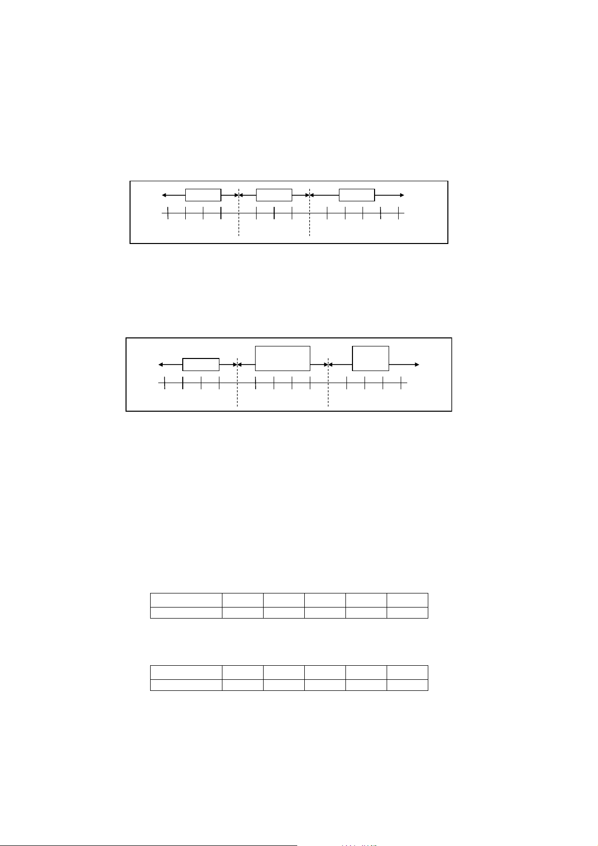
34
12.1.5 Automatic Operation
This mode can be set using remote control and the operation is decided by remote control setting temperature,
remote control operation mode and indoor intake air temperature.
During operation mode judgment, indoor fan motor (with speed of Lo-) is running for 30 seconds to detect the
indoor intake air temperature.
Every 10 minutes, the indoor temperature is judged.
For the 1st judgment
o If indoor intake temperature - remote control setting temperature ≥ 3.6°F (2°C), COOL mode is decided.
o If -3.6°F (-2°C) ≤ indoor intake temperature - remote control setting temperature < 3.6°F(2°C), DRY mode is
decided.
o If indoor intake temperature - remote control setting temperature < -3.6°F (-2°C), HEAT mode is decided.
For the 2nd judgment onwards
o If indoor intake temperature - remote control setting temperature ≥ 5.4°F (3°C), if previous operate in DRY
mode, then continue in DRY mode. otherwise COOL mode is decided.
o If -3.6°F (-2°C) ≤ indoor intake temperature - remote control setting temperature < 5.4°F (3°C), maintain with
previous mode.
o If indoor intake temperature - remote control setting temperature < -3.6°F (-2°C), HEAT mode is decided.
12.1.6 Fan Operation
Fan Operation is used to circulate air in a room.
During operation, indoor fan run continuously but outdoor fan and compressor stop.
Temperature setting is not applicable.
12.2 Indoor Fan Motor Operation
12.2.1 Basic Rotation Speed (rpm)
A. Basic Rotation Speed (rpm)
i. Manual Fan Speed
[Cooling, Dry]
Fan motor’s number of rotation is determined according to remote control setting.
Remote control ○ ○ ○ ○ ○
Tab Hi Me+ Me Me- Lo
[Heating]
Fan motor’s number of rotation is determined according to remote control setting.
Remote control ○ ○ ○ ○ ○
Tab SHi Me+ Me Me- Lo
-10.8
(-6)
-9.0
(-5)
-7.2
(-4)
-5.4
(-3)
-3.6
(-2)
-1.8
(-1)
0
(0)
1.8
(1)
3.6
(2)
5.4
(3)
7.2
(4)
9.0
(5)
10.8
(6)
Unit: F(C)
Heat Dr
y
Cool
-
Heat
Maintain
current mode
Cool
/Dry
-10.8
(-6)
-9.0
(-5)
-7.2
(-4)
-5.4
(-3)
-3.6
(-2)
-1.8
(-1)
0
(0)
1.8
(1)
3.6
(2)
5.4
(3)
7.2
(4)
9.0
(5)
10.8
(6)
Unit: F(C)
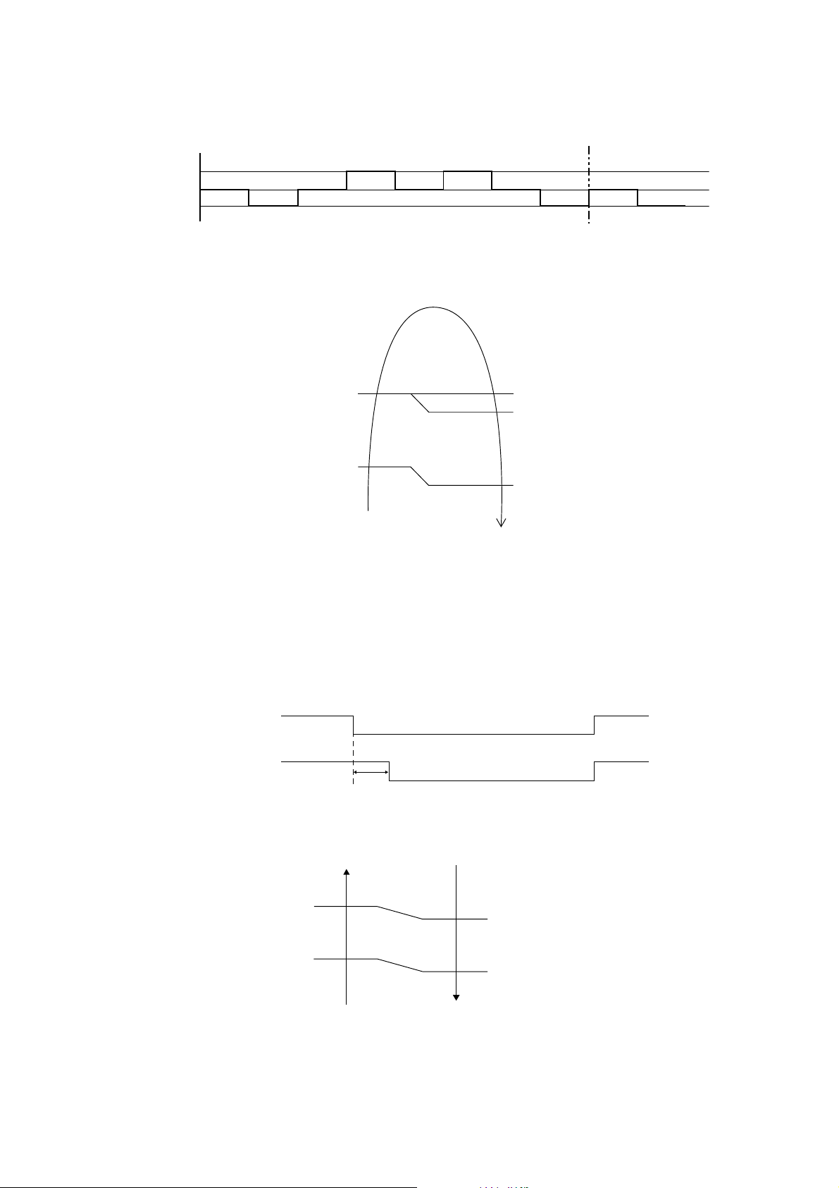
35
ii. Auto Fan Speed
[Cooling, Dry]
According to room temperature and setting temperature, indoor fan speed is determined automatically.
When set temperature is not achieved, the indoor fan will operate according to pattern below.
When set temperature achieved, the indoor fan speed will be fixed. When thermostat off, the fan stop periodically.
[Heating]
According to indoor pipe temperature, automatic heating fan speed is determined as follows.
B. Feedback control
Immediately after the fan motor started, feedback control is performed once every second.
During fan motor on, if fan motor feedback ≥ 2550 rpm or < 50 rpm continue for 10 seconds, then fan motor error
counter increase, fan motor is then stop and restart. If the fan motor counter becomes 7 times, then H19 - fan
motor error is detected. Operation stops and cannot on back.
12.3 Outdoor Fan Motor Operation
It starts when compressor starts operation and it stops 30 seconds after compressor stops operation.
During cooling operation, and outdoor ambient temperature is below 46.4°F (8°C), outdoor fan speed will be
controlled according to outdoor piping temperature as following:
abc def gh
[1 pattern : 10 s]
ab
Higher
F
a
n
Speed
Medium
L
ower
RPM Increased
RPM Maintain
RPM Reduced
OFF
Indoor Pipe Temp.
95
o
F(35
o
C)
102.2
o
F(39
o
C)
60.8
o
F(16
o
C)
66.2
o
F(19
o
C)
ON
Compressor:
Outdoor Fan:
ON
ON
OFF
OFF
Fan Speed
30 sec
ON
OD Pipe Te
m
p.
Outdoor fan
speed increased
Outdoor fan
speed reduce
Outdoor fan
speed maintain
B
A
A -5.4°F (A -3°C)
B -5.4°F (B -3°C)
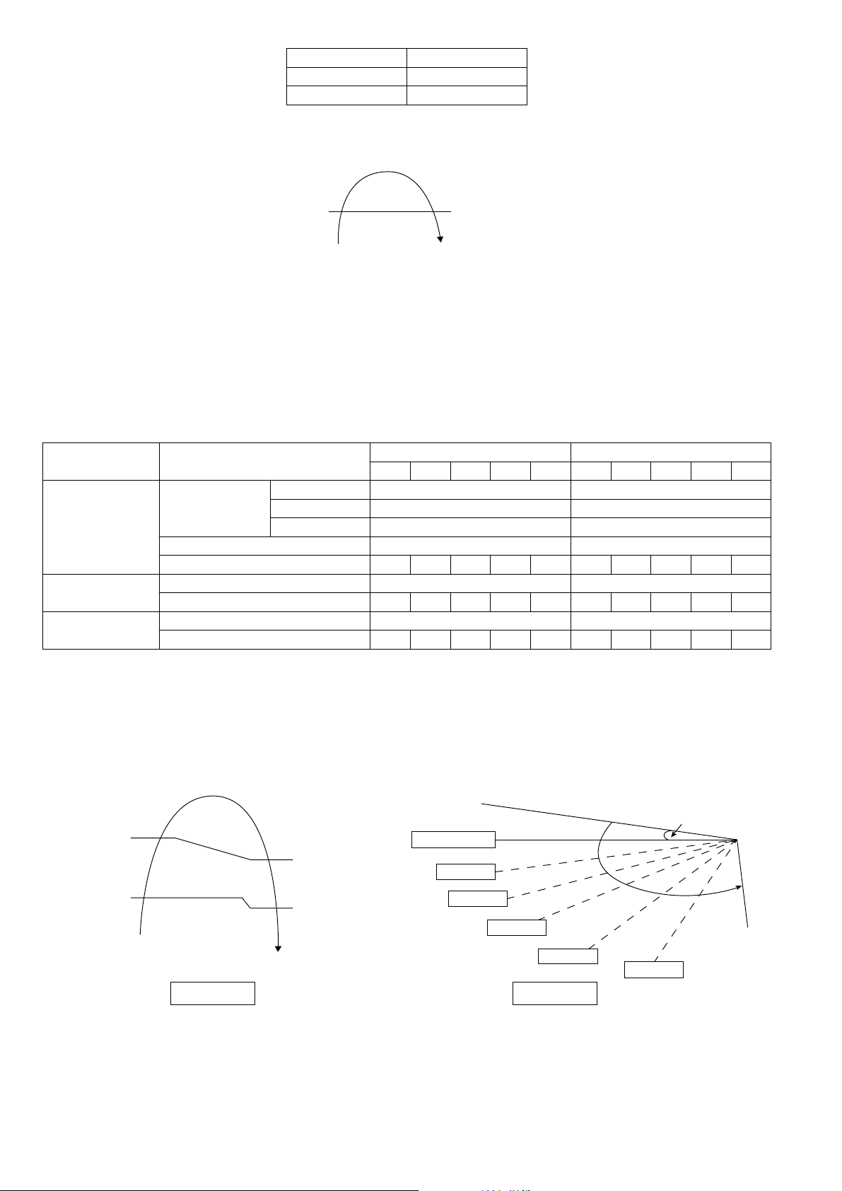
36
OD Pipe Temperature
A 78.8°F (26°C)
B 91.4°F (33°C)
During above condition, when indoor heat exchanger temperature is below 41°F (5°C), the outdoor fan will stop
according to outdoor piping temperature as following:
12.4 Airflow Direction
There are two types of airflow, vertical airflow (directed by horizontal vane) and horizontal airflow (directed by
vertical vanes).
Control of airflow direction can be automatic (angles of direction is determined by operation mode, heat
exchanger temperature and intake air temperature) and manual (angles of direction can be adjusted using
remote control).
12.4.1 Vertical Airflow
Operation Mode Airflow Direction
Upper Vane Angle (°) Lower Vane Angle (°)
1 2 3 4 5 1 2 3 4 5
Heating
Auto with Heat
Exchanger
Temperature
A 25 17
B 55 37
C 25 17
Summer House 55 37
Manual 20 45 55 65 70 17 27 37 47 56
Cooling
Auto 45 ~ 70 2 ~ 39
Manual 20 25 50 55 70 2 7 17 27 39
Soft Dry
Auto 45 ~ 70 2 ~ 39
Manual 20 25 50 55 70 2 7 17 27 39
1. Automatic vertical airflow direction can be set using remote control; the vane swings up and down within the
angles as stated above. For heating mode operation, the angle of the vane depends on the indoor heat
exchanger temperature as Figure 1 below. It does not swing during fan motor stop. When the air conditioner is
stopped using remote control, the vane will shift to close position.
2. Manual vertical airflow direction can be set using remote control; the angles of the vane are as stated above and
the positions of the vane are as Figure 2 below. When the air conditioner is stopped using remote control, the
vane will shift to close position.
OD Pipe Temp.
Outdoor
fan OFF
Outdoor
fan ON
86°F (30°C)
122.0°F (50°C)
Upper vane: 60°
Lower vane: 58°
86.0°F (30°C)
C
B
A
Indoor Heat
Exchanger Temperature
Closed Position
Figure 1
96.8°F (36°C)
136.4°F (58°C)
Figure 2
Step 3
Step 2
Step 1
Reference point
Step 4
Step 5
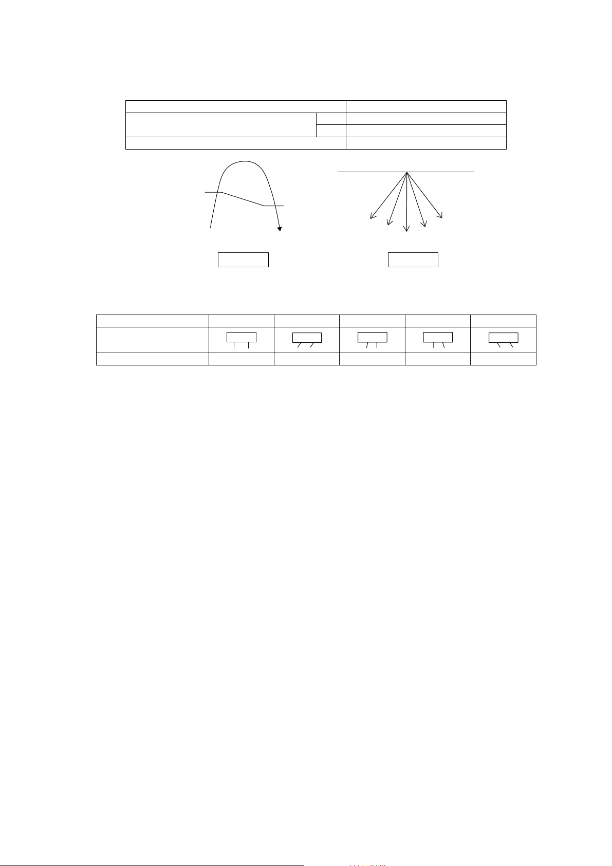
37
12.4.2 Horizontal Airflow
Automatic horizontal airflow direction can be set using remote control; the vane swings left and right within the
angles as stated below. For heating mode operation, the angle of the vane depends on the indoor heat
exchanger temperature as Figure 1 below. It does not swing during fan motor stop.
Operation Mode Vane Angle (°)
Heating, with heat exchanger temperature
A 65 ~115
B 90
Cooling and soft dry 65 ~115
Manual horizontal airflow direction can be set using remote control; the angles of the vane are as stated below
and the positions of the vane are as Figure 2 above.
Pattern 1 2 3 4 5
Airflow Direction Patterns at
Remote Control
Vane Angle (°) 90 65 77.5 102.5 115
12.5 Quiet operation (Cooling Mode/Cooling area of Dry Mode)
Purpose
o To provide quiet cooling operation compare to normal operation.
Control condition
o Quiet operation start condition
When “POWERFUL/QUIET” button at remote control is pressed twice.
POWERFUL/QUIET LED illuminates.
o Quiet operation stop condition
When one of the following conditions is satisfied, quiet operation stops:
POWERFUL/QUIET button is pressed again.
Stop by OFF/ON switch.
Timer “off” activates.
AUTO COMFORT button is pressed.
ECONAVI button is pressed.
When quiet operation is stopped, operation is shifted to normal operation with previous setting.
When fan speed is changed, quiet operation is shifted to quiet operation of the new fan speed.
When operation mode is changed, quiet operation is shifted to quiet operation of the new mode.
During quiet operation, if timer “on” activates, quiet operation maintains.
After off, when on back, quiet operation is not memorised.
Control contents
o Fan speed is changed from normal setting to quiet setting of respective fan speed.
Fan speed for quiet operation is reduced from setting fan speed.
12.6 Quiet Operation (Heating)
Purpose
o To provide quiet heating operation compare to normal operation.
Control condition
o Quiet operation start condition
When “POWERFUL/QUIET” button at remote control is pressed.
POWERFUL/QUIET LED illuminates.
109.4°F (43°C)
104°F (40°C)
0° Top View
2
3
1
4
5
B: fix front
A: swing
Indoor Heat Exchanger
Temperature
Figure 1 Figure 2
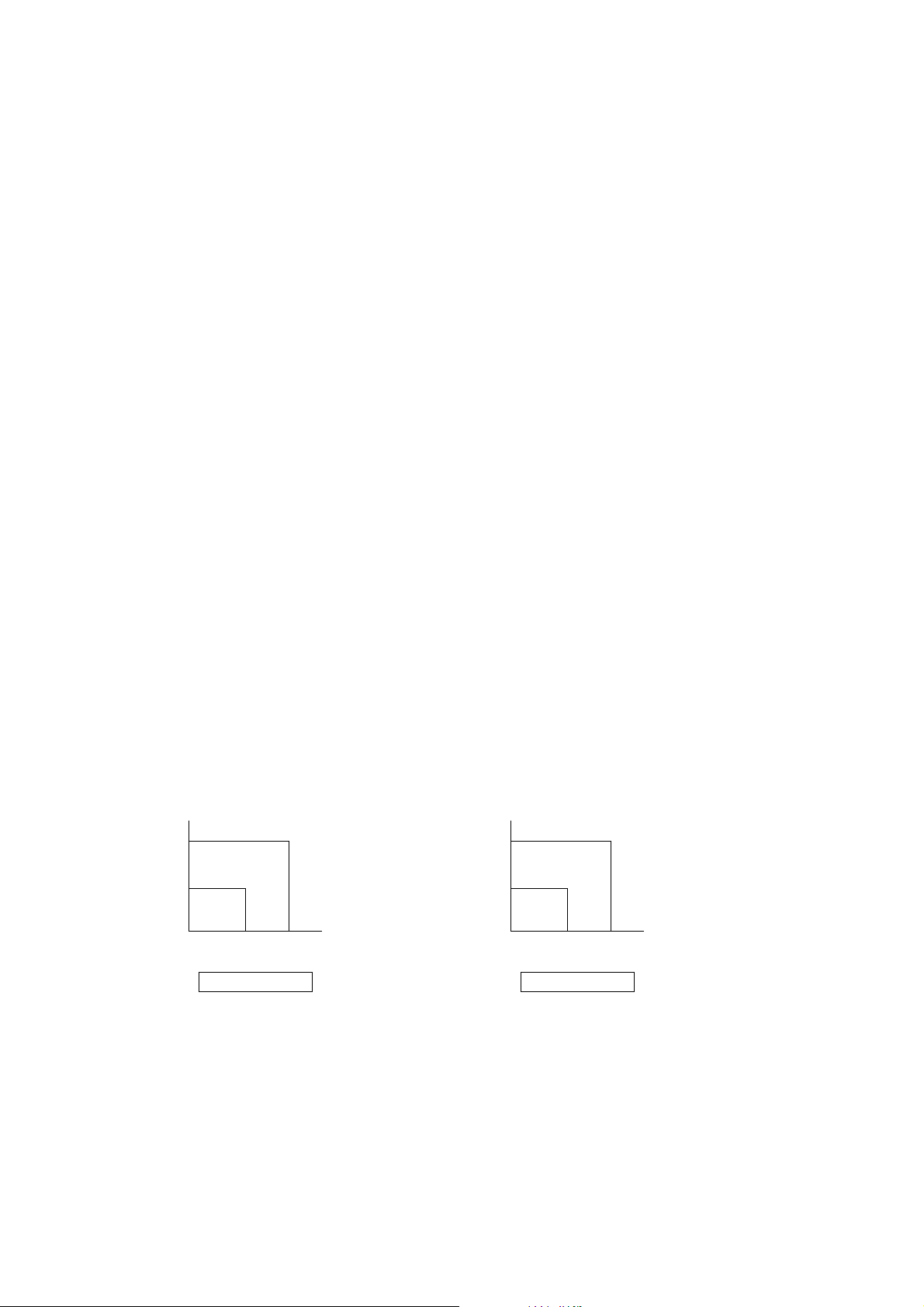
38
o Quiet operation stop condition
When one of the following conditions is satisfied, quiet operation stops:
POWERFUL/QUIET button is pressed again.
Stop by OFF/ON switch.
Timer “off” activates.
AUTO COMFORT button is pressed.
ECONAVI button is pressed.
When quiet operation is stopped, operation is shifted to normal operation with previous setting.
When fan speed is changed, quiet operation is shifted to quiet operation of the new fan speed.
When operation mode is changed, quiet operation is shifted to quiet operation of the new mode, except
fan mode only.
During quiet operation, if timer “on” activates, quiet operation maintains.
After off, when on back, quiet operation is not memorised.
Control contents
o Fan speed manual
Fan speed is changed from normal setting to quiet setting of respective fan speed.
Fan speed for quiet operation is reduced from setting fan speed.
o Fan Speed Auto
Indoor FM RPM depends on pipe temp sensor of indoor heat exchanger.
12.7 Powerful Mode Operation
When the powerful mode is selected, the internal setting temperature will shift lower up to 3.6°F (2°C) (for
Cooling/Soft Dry) or higher up to 6.3°F (3.5°C) (for Heating) than remote control setting temperature for
20 minutes to achieve the setting temperature quickly.
12.8 Timer Control
There are 2 sets of ON and OFF timer available to turn the unit ON or OFF at different preset time.
If more than one timer had been set, the upcoming timer will be displayed and will activate in sequence.
12.8.1 ON Timer Control
ON timer 1 and ON timer 2 can be set using remote control, the unit with timer set will start operate earlier than
the setting time.
This is to provide a comfortable environment when reaching the set ON time.
60 minutes before the set time, indoor (at fan speed of Lo-) and outdoor fan motor start operate for 30 seconds to
determine the indoor intake air temperature and outdoor air temperature in order to judge the operation starting
time.
From the above judgment, the decided operation will start operate earlier than the set time as shown below.
12.8.2 OFF Timer Control
OFF timer 1 and OFF timer 2 can be set using remote control, the unit with timer set will stop operate at set time.
12.9 Auto Restart Control
When the power supply is cut off during the operation of air conditioner, the compressor will re-operate within
three to four minutes (there are 10 patterns between 2 minutes 58 seconds and 3 minutes 52 seconds to be
selected randomly) after power supply resumes.
This type of control is not applicable during ON/OFF Timer setting.
This control can be omitted by open the circuit of JP1 at indoor unit printed circuit board.
Indoo
r
intak
e
ai
r
temperature
o
F(
o
C)
Outdoor air
temperature
o
F(
o
C)
86 (30)
86 (30) 95 (35)
Cooling/Soft Dry
10 min
15 min
5min
77 (25)
Indoo
r
intak
e
ai
r
temperature
o
F(
o
C)
Outdoor air
temperature
o
F(
o
C)
59 (15)
32 (0) 41 (5)
Heating
30 min
25 min
35 min
41 (5)

39
12.10 Indication Panel
LED POWER TIMER POWERFUL/QUIET RFP ECONAVI AUTO COMFORT
Color Green Orange Orange Green Green Green
Light ON Operation ON Timer Setting ON
POWERFUL/QUIET
Mode ON
RFP ON ECONAVI ON
AUTO COMFORT
ON
Light OFF Operation OFF Timer Setting OFF
POWERFUL/QUIET
Mode OFF
RFP OFF ECONAVI OFF
AUTO COMFORT
OFF
Note:
If POWER LED is blinking, the possible operation of the unit are Hot Start, during Deice operation, operation
mode judgment, or ON timer sampling.
If Timer LED is blinking, there is an abnormality operation occurs.
12.11 Room Freeze Protection Function (RFP) Operation
When the RFP is selected, the unit will operate the fan at high speed for proper room temperature monitoring.
When the sensor detects that the room temperature has dropped below 46°F / 8°C, the compressor/heat pump
operation begins.
When the room temperature reaches 50°F / 10°C, the unit shuts off, then will repeat continuously if the
temperature drops below 46°F / 8°C again.
<Disclaimer>
This function may not be performed if the unit is not energized, or under a certain condition that unit is unable to
operate such as in protection mode. Please consult with the HVAC installers or professional for details.
The Room Freeze Protection function (RFP) cannot be used unless the unit is energized and set into the RFP
mode.
In the advent of a power failure this mode will not function. During the RFP mode, POWERFUL OPERATION,
QUIET OPERATION and FAN SPEED selection are all disabled. Please consult with your HVAC installer or
professional for more details.
12.12 AUTO COMFORT and ECONAVI Operation
Area of human availability, activity level and absent is judged based on pulses by using 2 infrared sensors. The
internal setting temperature shift, fan speed and horizontal airflow direction are adjusted in order to provide
comfort environment while maintain the energy saving level.
AUTO COMFORT start condition:
o When AUTO COMFORT button is pressed.
AUTO COMFORT stop conditions:
o When AUTO COMFORT button is pressed again.
o When unit is OFF by OFF/ON button.
o When unit is OFF when OFF TIMER activates.
o When unit is OFF by AUTO OFF/ON button at indoor unit.
o When POWERFUL, QUIET operation activates.
o When AIR SWING ◄► button is pressed.
ECONAVI start condition:
o When ECONAVI button is pressed.
ECONAVI stop conditions:
o When ECONAVI button is pressed again.
o When unit is OFF by OFF/ON button.
o When unit is OFF when OFF TIMER activates.
o When unit is OFF by AUTO OFF/ON button at indoor unit.
o When POWERFUL, QUIET operation activates.
o When AIR SWING ◄► button is pressed.
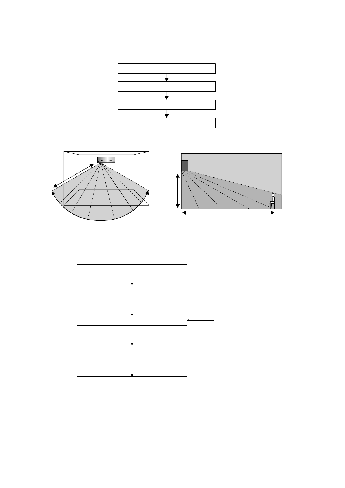
40
12.12.1 Human Activity Sensor
Area of human availability, activity level and absent is judged based on pulses by using infrared sensor. The
internal setting temperature shift, fan speed and horizontal airflow direction are adjusted in order to provide
comfort environment while maintain the energy saving level.
Human activity judgment is as following:
12.12.1.1 Signal Detection
Presumption flow of human position.
o Detection outline.
12.12.1.2 Information Log
The signal from Infrared sensors will be log to human activity database for further analysis.
12.12.1.3 Human Activity Level Judgment
Human Activity Level is judged based on the frequency of pulses detected by the infrared sensors within a
timeframe. The activity level will be categorized into High, Normal, Low level.
When a pulse is detected within this timeframe, the status of human presence is judged.
When there is no signal detection continues for 40 minutes or more, the status of human absence is judged.
Signal Detection
Information Log
Human Activity Level Judgment
Determination of Presence or Absence
C
B
A
7m
120°
7m
2m
Human Sensor Motion Check
Sensor move to left and
right and detection area
(A, B, C) output frequency
is detected
Check Installation Position and Detection Area
Human Sensor STM move
Fixed Detection
Process Detection Result
Determination of fixed
detection area and its order
(Fixed detection i
s
continued until it
measures all the
detection area)
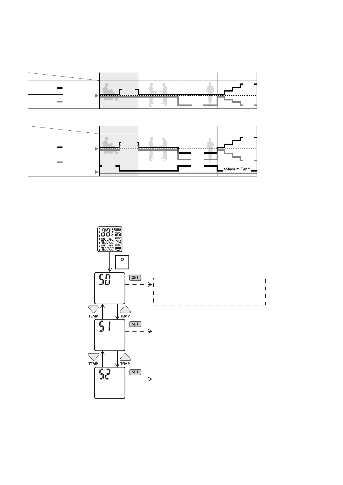
41
12.12.1.4 Determination of Presence or Absence
Human presence status shall be determined based on the human presence status of each area.
When all area has been detected absent for more than 40 minutes then it will judge as absence.
12.12.1.5 Setting Temperature and Fan Speed Shift
* During low activity, fan speed 1 tap up for first 15 minutes or until set temperature is reached.
** During human absence, maximum fan speed for COOL/DRY mode is medium fan.
12.12.1.6 ECONAVI and AUTO COMFORT Demo Mode
To enable ECO DEMO mode:
To disable ECO Demo MODE:
o Transmit ECO Demo signal again.
Low activity Normal activity
Human
Mode
Set
temperature
High activity Absent
ECONA
V
I ; Detecting human presence and activity, the unit controls room temperature to save energy.
Low activity Normal activity
Human
Mode
Set
temperature
High activity Absent
Set
Fan Speed
A
UTO COMFORT ; Detecting human presence and activity, the unit controls room temperature to keep human
comfortable consistently.
HEAT
COOL/DRY
HEAT
COOL/DRY
+1 tap
+1 tap*
+2°F / +1°C
+2°F / +1°C
+0.5°F / +0.3°C
-2°F / -1°C
-4°F / -2°C
+4°F / +2°C
-4°F / -2°C
-4°F / -2°C
+4°F / +2°C
-4°F / -2°C
SET
Transmit ECO demo code and
after 30 seconds return to normal
mode.
Press continously for 5s
Transmit check code
and after 30 seconds return to normal
mode.
Transmit sunlight sensor check code
and after 30 seconds return to normal
mode.
Remote control normal mode
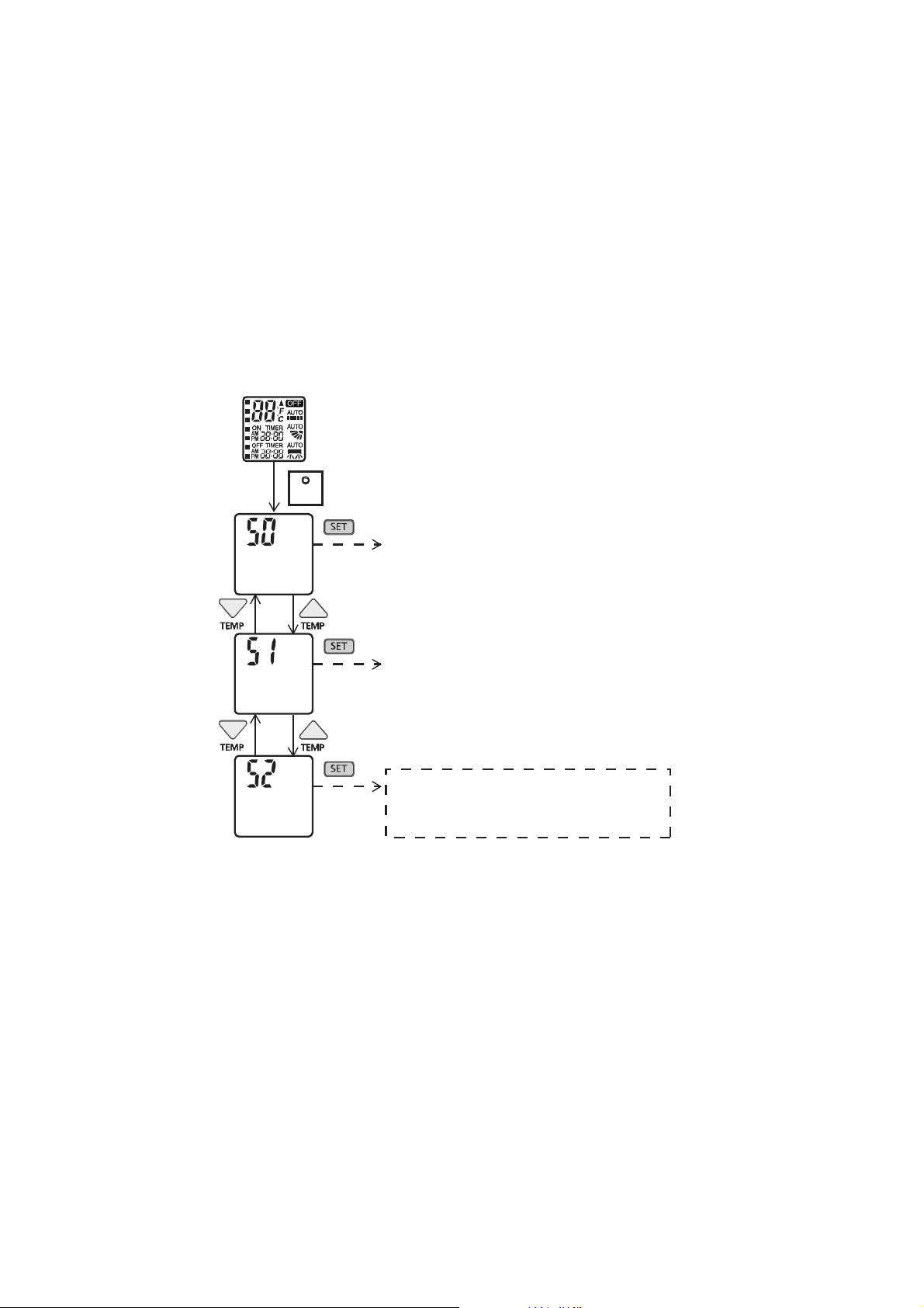
42
12.12.1.7 Human Activity Sensor Abnormality
Abnormality detection:
Connector disconnection / Wire cut abnormality
o Sensor judge Hi level continuously for 25 seconds
Circuit abnormality
o 70 seconds after power ON, if human activity sensor judge Lo level continuously for 25 seconds
Error Code judgment
When abnormality happened, internal counter increase by 1 time.
Human activity sensor power OFF, retry after 5 seconds.
When the human activity sensor maintains normal condition for 120 seconds, the counter reset or AC reset.
When abnormality counter reached 4 times, H59 occurred – No TIMER indicator blinking.
When error code happened, the unit is able to operate without AUTO COMFORT / ECONAVI.
12.12.1.8 Human Activity Sensor Check Mode
To enable human activity sensor abnormality check mode:
During ECONAVI is ON, when CHECK signal received, if either sensors has abnormality, the 4 times abnormality
counter is ignored, ECONAVI Indicator will blink immediately and error code is memorized.
The unit could operate without ECONAVI or AUTO COMFORT.
The ECONAVI indicator blinking could be cancelled by pressing ECONAVI button again.
If the human activity sensor has no abnormality, the CHECK process will end and continue with normal operation.
SET
Transmit ECO demo code and
after 30 seconds return to normal
mode.
Press continously for 5s
Transmit check code
and after 30 seconds return to normal
mode.
Transmit sunlight sensor check code
and after 30 seconds return to normal
mode.
Remote control normal mode
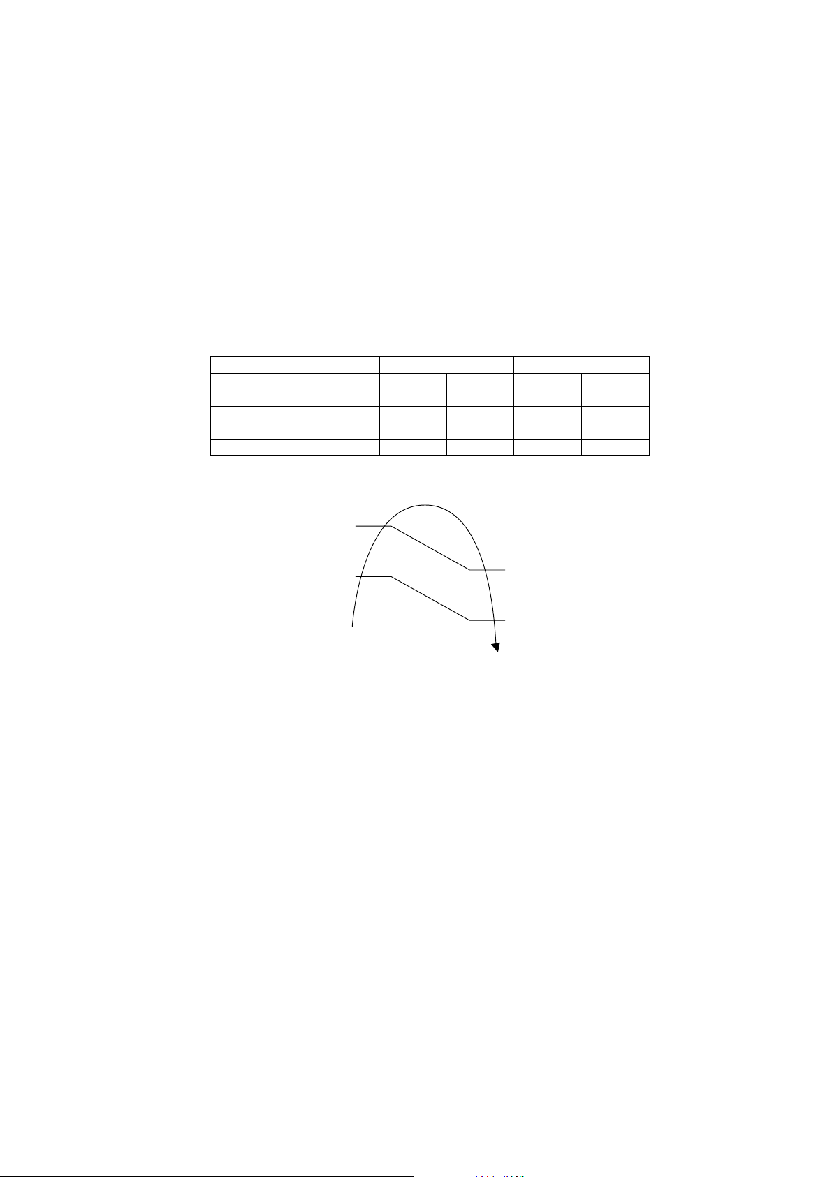
43
13. Protection Control
13.1 Protection Control For All Operations
13.1.1 Restart Control (Time Delay Safety Control)
The Compressor will not turn on within 3 minutes from the moment operation stops, although the unit is turned on
again by pressing OFF/ON button at remote control within this period.
This control is not applicable if the power supply is cut off and on again.
This phenomenon is to balance the pressure inside the refrigerant cycle.
13.1.2 Total Running Current
1 When the outdoor unit total running current (AC) exceeds X value, the frequency instructed for compressor
operation will be decreased.
2 If the running current does not exceed X value for 5 seconds, the frequency instructed will be increased.
3 However, if total outdoor unit running current exceeds Y value, compressor will be stopped immediately for
3 minutes.
Model XE9SKUA XE12SKUA
Operation Mode X (A) Y (A) X (A) Y (A)
Cooling / Soft Dry (A) 6.48 15.00 7.70 15.00
Cooling / Soft Dry (B) 6.48 15.00 7.70 15.00
Heating 7.48 15.00 9.20 15.00
Cooling / Soft Dry (C) 6.48 15.00 7.70 15.00
4 The first 30 minutes of cooling operation, (A) will be applied.
13.1.3 IPM (Power transistor) Prevention Control
Overheating Prevention Control
1 When the IPM temperature rises to 248°F (120°C), compressor operation will stop immediately.
2 Compressor operation restarts after 3 minutes the temperature decreases to 230°F (110°C).
3 If this condition repeats continuously 4 times within 20 minutes, timer LED will be blinking (“F96” is indicated).
DC Peak Current Control
1 When electric current to IPM exceeds set value of 16.0 ±2.0A, the compressor will stop operate. Then,
operation will restart after 3 minutes.
2 If the set value is exceeded again more than 30 seconds after the compressor starts, the operation will
restart after 1 minute.
3 If the set value exceeded again within 30 seconds after the compressor starts, the operation will restart after
1 minute. If this condition repeats continuously for 7 times, all indoor and outdoor relays will be cut off, timer
LED will be blinking (“F99” is indicated).
102.2°F (39.0°C)
100.4°F (38.0°C)
109.4°F (43.0°C)
107.6°F (42.0°C)
(B)
(C)
(A)
Outdoor air temperature
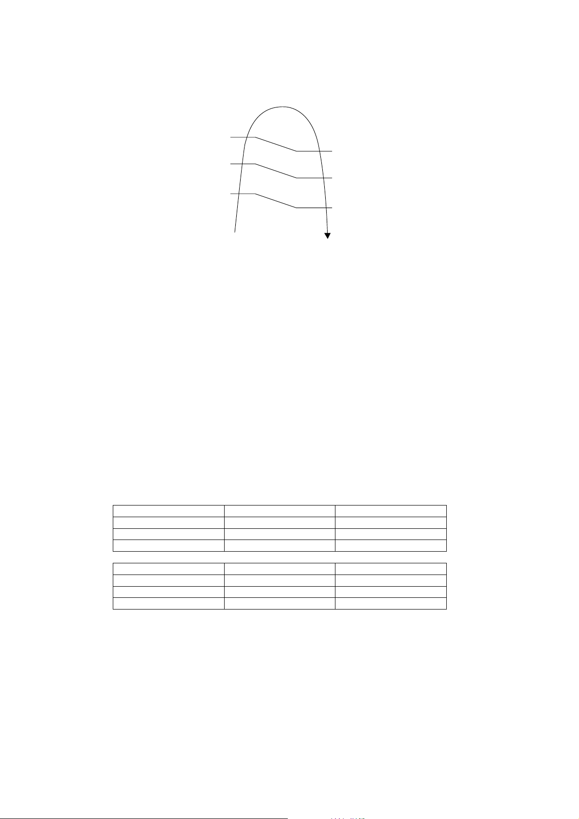
44
13.1.4 Compressor Overheating Prevention Control
Instructed frequency for compressor operation will be regulated by compressor discharge temperature. The
changes of frequency are as below.
If compressor discharge temperature exceeds 224.6°F (107°C), compressor will be stopped, occurs 4 times per
20 minutes, timer LED will be blinking. (“F97” is indicated.)
13.1.5 Low Pressure Prevention Control (Gas Leakage Detection)
Control start conditions
o For 5 minutes, the compressor continuously operates and outdoor total current is between 0.75A and 0.95A.
o During Cooling and Soft Dry operations:
Indoor suction temperature - indoor piping temperature is below 7.2°F (4°C).
o During Heating operations :
Indoor piping temperature - indoor suction is under 9°F (5°C).
Control contents
o Compressor stops (and restart after 3 minutes).
o If the conditions above happen 2 times within 20 minutes, the unit will:
Stop operation
Timer LED blinks and “F91” indicated.
13.1.6 Low Frequency Protection Control 1
When the compressor operate at frequency lower than 24 Hz continued for 20 minutes, the operation frequency
will be changed to 23 Hz for 2 minutes.
13.1.7 Low Frequency Protection Control 2
When all the below conditions comply, the compressor frequency will change to lower frequency.
Temperature, T, for: Cooling/Soft Dry Heating
Indoor intake air (°C) T < 14 or T ≥ 30 T < 14 or T ≥ 28
Outdoor air (°C) T < 13 or T ≥ 38 T < 4 or T ≥ 24
Indoor heat exchanger (°C) T < 30 T ≥ 0
Temperature, T, for: Cooling/Soft Dry Heating
Indoor intake air (°F) T < 57.2 or T ≥ 86.0 T < 57.2 or T ≥ 82.4
Outdoor air (°F) T < 55.4 or T ≥ 100.4 T < 39.2 or T ≥ 75.2
Indoor heat exchanger (°F) T < 86.0 T ≥ 32.0
Compressor = OFF
Compressor Frequency
Reduce
Compressor Frequency
Maintain
Free
2
24.6°F (107°C)
2
17.4°F (103°C)
(221°F (105°C))
212°F (100°C)
(203°F (95°C))
197.6°F (92°C)
195.8°F (91°C)
194°F (90°C)
(185°F (85°C))
Comp. temperature
(Comp. Discharge temperature)
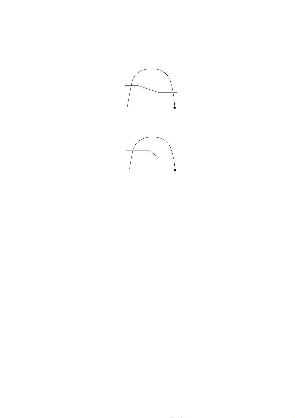
45
13.2 Protection Control For Cooling & Soft Dry Operation
13.2.1 Outdoor Air Temperature Control
The compressor operating frequency is regulated in accordance to the outdoor air temperature as shown in the
diagram below.
This control will begin 1 minute after the compressor starts.
Compressor frequency will adjust base on outdoor air temperature.
The compressor will be stopped to avoid compressor overloading.
13.2.2 Cooling Overload Control
Detects the Outdoor pipe temperature and carry out below restriction/limitation (Limit the compressor Operation
frequency).
The compressor stop if outdoor pipe temperature exceeds 141.8°F (61°C).
If the compressor stops 4 times in 20 minutes, Timer LED blinking (F95 indicated: outdoor high pressure rise
protection).
13.2.3 Freeze Prevention Control 1
When indoor heat exchanger temperature is lower than 32°F (0°C) continuously for 6 minutes, compressor will
stop operating.
Compressor will resume its operation 3 minutes after the indoor heat exchanger is higher than 41°F (5°C).
At the same time, indoor fan speed will be higher than during its normal operation.
If indoor heat exchanger temperature is higher than 41°F (5°C) for 5 minutes, the fan speed will return to its
normal operation.
13.2.4 Freeze Prevention Control 2
Control start conditions
o During Cooling operation and soft dry operation
During thermo OFF condition, indoor intake temperature is less than 50°F (10°C) or
Compressor stops for freeze prevention control
o Either one of the conditions above occurs 5 times in 60 minutes.
Control contents
o Operation stops
o Timer LED blinks and “H99” indicated
Limited Frequency
Free
77°F (25°C)
71.6°F (22°C)
Outdoor
Air
Temperature
Comp. OFF
Comp. ON
0°F (-17.8°C)
-4.0°F (-20°C)
Outdoor
Air Temperature
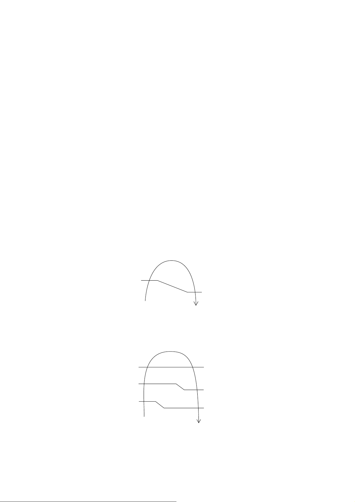
46
13.2.5 Dew Prevention Control 1
To prevent dew formation at indoor unit discharge area.
This control will be activated if:
o Outdoor air temperature and Indoor pipe temperature judgment by microcontroller is fulfilled.
o When Cooling or Dry mode is operated more than 20 minutes or more.
This control stopped if:
o Compressor stopped.
o Remote control setting changed (fan speed / temperature).
o Outdoor air temperature and indoor intake temperature changed.
Fan speed will be adjusted accordingly in this control.
13.2.6 Odor Cut Control
To reduce the odor released from the unit.
o Start Condition
AUTO FAN Speed is selected during COOL or DRY operation.
During freeze prevention control and timer preliminary operation, this control is not applicable.
o Control content
Depends on compressor conditions:
1. Compressor OFF → Compressor ON.
The indoor unit fan stops temporarily and then starts to blow at minimum airflow for 30 seconds.
2. Compressor ON → Compressor OFF.
The indoor unit fan stops for 90 seconds and then blows at minimum airflow for 20 seconds.
13.3 Protection Control For Heating Operation
13.3.1 Intake Air Temperature Control
Compressor will operate at limited freq., if indoor intake air temperature is 86°F (30°C) or above.
13.3.2 Outdoor Air Temperature Control
The Max current value is regulated when the outdoor air temperature rise above 57.2°F (14°C) in order to avoid
compressor overloading.
13.3.3 Overload Protection Control
The compressor operating frequency is regulated in accordance to indoor heat exchanger temperature as shown
below.
If the heat exchanger temperature exceeds 140°F (60°C), compressor will stop.
13.3.4 Low Temperature Compressor Oil Return Control
In heating operation, if the outdoor temperature falls below 14°F (-10°C) when compressor starts, the
compressor frequency will be regulated up to 600 seconds.
Current Regulated
Free Within Max Limit
53.6°F (12°C)
Outdoor air temperature
57.2°F (14°C)
OFF
Frequency Reduce
Frequency Limited
Free
Indoor Heat
Exchanger Temp.
140°F (60°C)
125.6°F (52°C)
114.8°F (46°C)
131°F (55°C)
120.2°F (49°C)

47
13.3.5 Cold Draught Prevention Control
When indoor pipe temperature is low, cold draught operation starts where indoor fan speed will be reduced.
13.3.6 Deice Operation
When outdoor pipe temperature and outdoor air temperature is low, deice operation start where indoor fan motor
and outdoor fan motor stop and operation LED blinks.
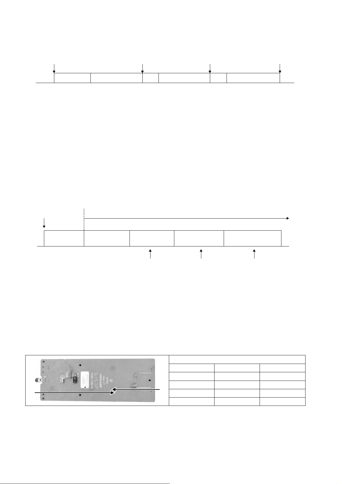
48
14. Servicing Mode
14.1 Auto OFF/ON Button
1 AUTO OPERATION MODE
The Auto operation will be activated immediately once the Auto OFF/ON button is pressed. This operation
can be used to operate air conditioner with limited function if remote control is misplaced or malfunction.
2 TEST RUN OPERATION (FOR PUMP DOWN/SERVICING PURPOSE)
The Test Run operation will be activated if the Auto OFF/ON button is pressed continuously for more than
5 seconds. A “beep” sound will heard at the fifth seconds, in order to identify the starting of Test Run
operation (Forced cooling operation). Within 5 minutes after Forced cooling operation start, the Auto OFF/ON
button is pressed for more than 5 seconds. A 2 “beep” sounds will heard at the fifth seconds, in order to
identify the starting of Normal cooling operation.
Within 5 minutes after Normal cooling operation start, the Auto OFF/ON button is pressed for more than
5 seconds. A 3 “beep” sounds will be heard at the fifth seconds, in order to identify the starting of Forced
heating operation.
The Auto OFF/ON button may be used together with remote control to set / change the advance setting of air
conditioner operation.
3 REMOTE CONTROL NUMBER SWITCH MODE
The Remote Control Number Switch Mode will be activated if the Auto OFF/ON button is pressed
continuously for more than 11 seconds (3 “beep” sounds will occur at 11th seconds to identify the Remote
Control Number Switch Mode is in standby condition) and press “AC RESET” button and then press any
button at remote control to transmit and store the desired transmission code to the EEPROM.
There are 4 types of remote control transmission code could be selected and stored in EEPROM of indoor
unit. The indoor unit will only operate when received signal with same transmission code from remote control.
This could prevent signal interference when there are 2 or more indoor units installed nearby together.
To change remote control transmission code, short or open jumpers at the remote control printed circuit
board.
Remote Control Printed Circuit Board
Jumper A (JA) Jumper B (JB) Remote Control No.
Short Open A (Default)
Open Open B
Short Short C
Open Short D
During Remote Control Number Switch Mode, press any button at remote control to transmit and store
the transmission code to the EEPROM.
Auto OFF/ON
Button pressed
5sec
Beep Beep x 2 Beep x 3
5sec 5sec
Auto Operation Test Run Operation
(Forced cooling operation)
Test Run Operation
(Forced heating operation)
Stop Normal Cooling Operation Stop Stop
Auto OFF
/
ON
Button pressed
Auto OFF
/
ON
Button pressed
Auto OFF
/
ON
Button pressed
Auto OFF/ON button
pressed
Auto Operation
5 sec 8 sec 11 sec 16 sec
Test Run Operation
(Forced Cooling Operation)
Test Run Operation
(Forced Heating Operation)
Main unit always continue Test Run (forced cooling) operation
Beep Beep x 2
Press “AC RESET”, then any
key at remote control
Press “AC RESET”, then any
key at remote control
Press “AC RESET”
at remote control
Beep x 3 Beep x 4
Remote Control Number
Switch Mode
Remote Control Receiving
Sound OFF/ON
JA
JB

49
4 REMOTE CONTROL RECEIVING SOUND OFF/ON MODE
The Remote Control Receiving Sound OFF/ON Mode will be activated if the Auto OFF/ON button is pressed
continuously for more than 16 seconds (4 “beep” sounds will occur at 16th seconds to identify the Remote
Control Receiving Sound Off/On Mode is in standby condition) and press “AC Reset” button at remote
control.
Press “Auto OFF/ON button” to toggle remote control receiving sound.
o Short “beep”: Turn OFF remote control receiving sound.
o Long “beep”: Turn ON remote control receiving sound.
After Auto OFF/ON Button is pressed, the 20 seconds counter for Remote Control Receiving Sound OFF/ON
Mode is restarted.
14.2 Remote Control Button
14.2.1 SET Button
To check remote control transmission code and store the transmission code to EEPROM:
o Press “Set” button by using pointer.
o Press “Timer Set” button until a “beep” sound is heard as confirmation of transmission code changed.
To limit set temperature range for COOL & DRY, HEAT mode.
o Press “Set” button by using pointer.
o Press TEMP increment or decrement button to choose No. 3.
o Press Timer increment or decrement button to select desired temperature low limit of set temperature for
COOL & DRY mode.
o Press Timer Set button to confirm low limit selection.
o Press TEMP increment or decrement button to choose No. 4.
o Press Timer decrement or increment button to select desired temperature high limit of set temperature for
COOL & DRY mode.
o Press Timer Set button to confirm high limit selection.
o Press TEMP increment or decrement button to choose No. 5.
o Press Timer increment or decrement button to select desired temperature low limit of set temperature for
HEAT mode.
o Press Timer Set button to confirm low limit selection.
o Press TEMP increment or decrement button to choose No. 6.
o Press Timer decrement or increment button to select desired temperature high limit of set temperature for
HEAT mode.
o Press Timer Set button to confirm high limit selection.
o LCD returns to original display if remote control does not operate for 30 seconds or press Timer Cancel
button.
14.2.2 RESET (RC)
To clear and restore the remote control setting to factory default.
o Press once to clear the memory.
14.2.3 RESET (AC)
To restore the unit’s setting to factory default.
o Press once to restore the unit’s setting.
14.2.4 TIMER ▲
To change indoor unit indicator’s LED intensity.
o Press continuously for 5 seconds.
14.2.5 TIMER ▼
To change remote control display from Degree Celsius (°C) to Degree Fahrenheit (°F).
o Press continuously for 10 seconds.
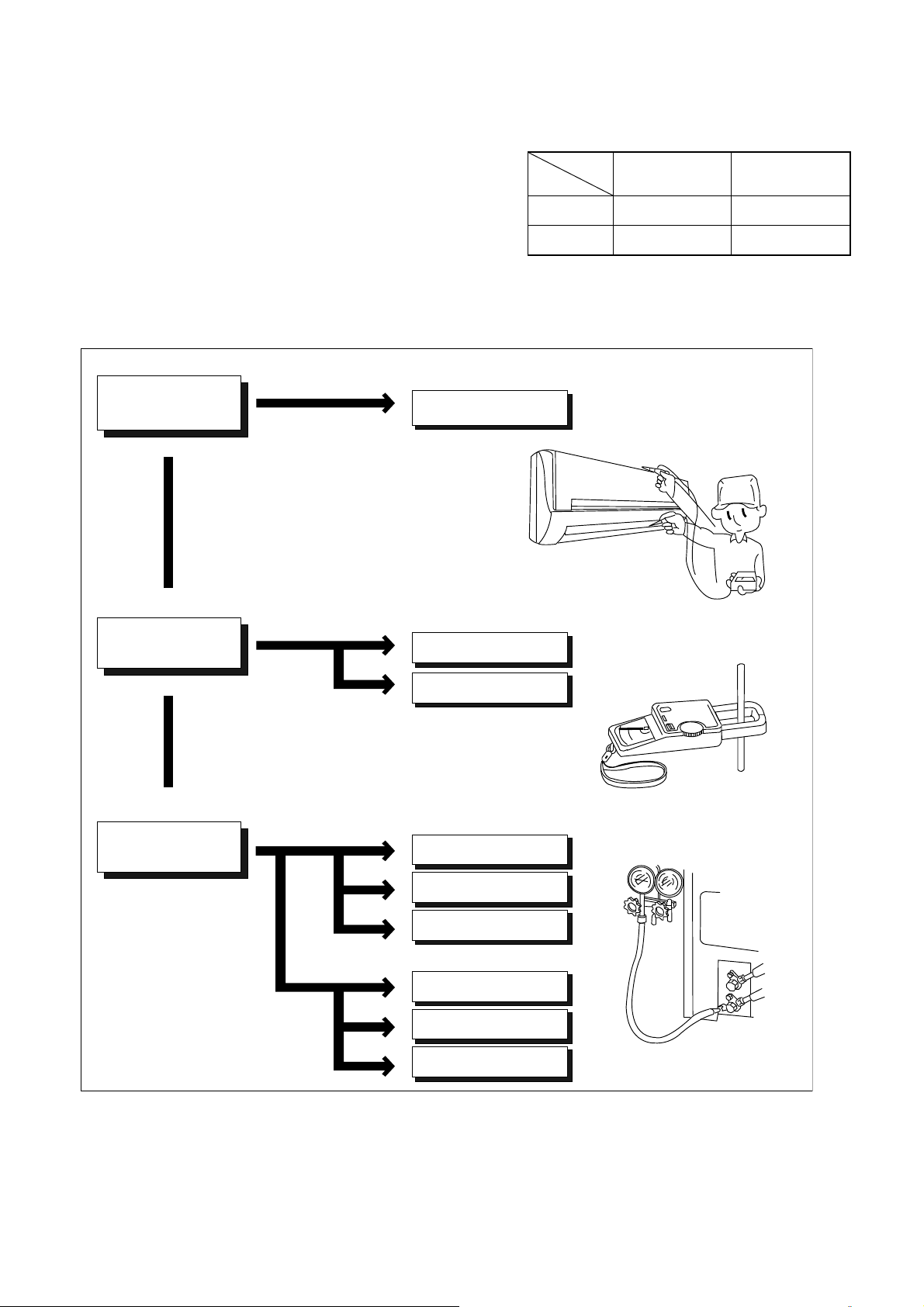
50
15. Troubleshooting Guide
15.1 Refrigeration Cycle System
In order to diagnose malfunctions, make sure that there are no
electrical problems before inspecting the refrigeration cycle.
Such problems include insufficient insulation, problem with the
power source, malfunction of a compressor and a fan.
The normal outlet air temperature and pressure of the refrigeration
cycle depends on various conditions, the standard values for them
are shown in the table on the right.
Value of electric
current during operation
Difference in the intake
and outlet
air temperatures
Lower than specified
Higher than specified
Cooling Mode
Heating Mode
High
Low
Low
Low
Low
Low
Gas side
pressure
Dusty condenser
preventing heat radiation
● Measuring electric current
during operation
● Measuring gas side pressure
Excessive amount
of refrigerant
Inefficient compressor
Insufficient refrigerant
Insufficient refrigerant
Inefficient compressor
Clogged strainer or
capillary tube
Clogged strainer or
capillary tube
Less than 14.4°F (8°C) at the cooling mode.
Less than 25.2°F (14°C) at the heating mode.
More than 14.4°F (8°C)
(15 minutes after an
operation is started.)
at cooling mode.
Above 25.2°F (14°C)
(15 minutes after an
operation is started.)
at heating mode
Normal
● Measuring the air temperature
difference
Normal Pressure and Outlet Air Temperature (Standard)
Gas Pressure
PSI
(kg/cm
2
G)
Outlet air
Temperature
°F (°C)
Cooling Mode
130.53 ~ 174.04
(9 ~ 12)
53.6 ~ 60.8
(12 ~ 16)
Heating Mode
333.58 ~ 420.60
(23 ~ 29)
96.8 ~ 113
(36 ~ 45)
*Condition: • Indoor fan speed = High
• Outdoor temperature 95°F (35°C) at the
Cooling mode and 44.6°F (7°C) at the
heating mode
• Compressor operates at rated frequency

51
15.1.1 Relationship between the condition of the air conditioner and pressure and
electric current
Condition of the
air conditioner
Cooling Mode Heating Mode
Low Pressure High Pressure
Electric current
during operation
Low Pressure High Pressure
Electric current
during operation
Insufficient refrigerant
(gas leakage)
Clogged capillary tube or
Strainer
Short circuit in the indoor unit
Heat radiation deficiency
of the outdoor unit
Inefficient compression
• Carry out the measurement of pressure, electric current, and temperature fifteen minutes after an operation is started.
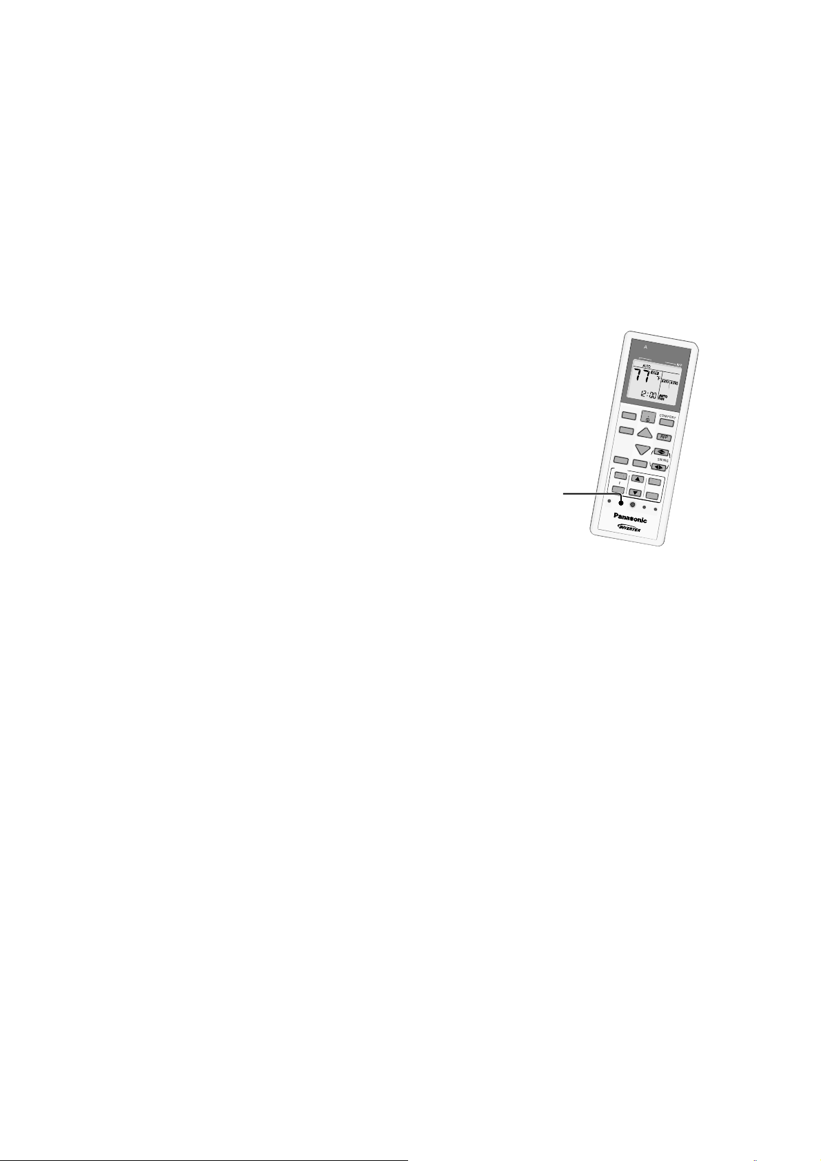
52
15.2 Breakdown Self Diagnosis Function
15.2.1 Self Diagnosis Function (Three Digits Alphanumeric Code)
Once abnormality has occurred during operation,
the unit will stop its operation, and Timer LED
blinks.
Although Timer LED goes off when power supply
is turned off, if the unit is operated under a
breakdown condition, the LED will light up again.
In operation after breakdown repair, the Timer
LED will no more blink. The last error code
(abnormality) will be stored in IC memory.
15.2.2 To Make a Diagnosis
1 Timer LED start to blink and the unit
automatically stops the operation.
2 Press the CHECK button on the remote
controller continuously for 5 seconds.
3 “- -” will be displayed on the remote controller
display.
Note: Display only for “- -”. (No transmitting
signal, no receiving sound and no Power LED
blinking.)
4 Press the “TIMER” ▲ or ▼ button on the
remote controller. The code “H00” (no
abnormality) will be displayed and signal will
be transmitted to the main unit.
5 Every press of the button (up or down) will
increase abnormality numbers and transmit
abnormality code signal to the main unit.
6 When the latest abnormality code on the main
unit and code transmitted from the remote
controller are matched, power LED will light
up for 30 seconds and a beep sound
(continuously for 4 seconds) will be heard. If
no codes are matched, power LED will light up
for 0.5 seconds and no sound will be heard.
7 The breakdown diagnosis mode will be
canceled unless pressing the CHECK button
continuously for 5 seconds or operating the
unit for 30 seconds.
8 The LED will be off if the unit is turned off or
the RESET button on the main unit is pressed.
15.2.3 To Display Memorized Error
Code (Protective Operation)
1 Turn power on.
2 Press the CHECK button on the remote
controller continuously for 5 seconds.
3 “- -” will be displayed on the remote controller
display.
Note: Display only for “- -”. (No transmitting
signal, no receiving sound and no Power LED
blinking.)
4 Press the “TIMER” ▲ or ▼ button on the
remote controller. The code “H00” (no
abnormality) will be displayed and signal will
be transmitted to the main unit. The power
LED lights up. If no abnormality is stored in
the memory, three beeps sound will be heard.
5 Every press of the button (up or down) will
increase abnormality numbers and transmit
abnormality code signal to the main unit.
6 When the latest abnormality code on the main
unit and code transmitted from the remote
controller are matched, power LED will light
up for 30 seconds and a beep sound
(continuously for 4 seconds) will be heard. If
no codes are matched, power LED will light up
for 0.5 seconds and no sound will be heard.
7 The breakdown diagnosis mode will be
canceled unless pressing the CHECK button
continuously for 5 seconds or operating the
unit for 30 seconds.
8 The same diagnosis can be repeated by
turning power on again.
15.2.4 To Clear Memorized Error Code
after Repair (Protective
Operation)
1 Turn power on (in standby condition).
2 Press the AUTO button for 5 seconds (A beep
receiving sound) on the main unit to operate
the unit at Forced Cooling Operation modes.
3 Press the CHECK button on the remote
controller for about 1 second with a pointed
object to transmit signal to main unit. A beep
sound is heard from main unit and the data is
cleared.
15.2.5 Temporary Operation (Depending
On Breakdown Status)
1 Press the AUTO button (A beep receiving
sound) on the main unit to operate the unit.
(Remote control will become possible.)
2 The unit can temporarily be used until
repaired.
C
L
O
C
K
A
I
R
C
O
N
D
I
T
I
O
N
E
R
O
F
F
/
O
N
S
E
T
C
H
E
C
K
R
E
S
E
T
A
C
R
C
O
N
O
F
F
S
E
T
1
2
3
T
I
M
E
R
A
U
T
O
C
O
M
F
O
R
T
P
O
W
E
R
F
U
L
/
Q
U
I
E
T
M
O
D
E
T
E
M
P
F
A
N
S
P
E
E
D
A
I
R
S
W
I
N
G
E
C
O
N
A
V
I
R
F
P
M
O
D
E
O
F
F
/
O
N
C
H
E
C
K
O
N
O
F
F
S
E
T
1
2
3
T
I
M
E
R
T
E
M
P
C
A
N
C
E
L
“Check” button

53
15.3 Error Codes Table
Diagnosis
display
Abnormality /
Protection control
Abnormality
Judgment
Protection
Operation
Problem Check location
H00 No memory of failure — Normal operation — —
H11
Indoor/outdoor
abnormal
communication
After operation for
1 minute
Indoor fan only
operation can
start by entering
into force cooling
operation
Indoor/outdoor
communication not
establish
Indoor/outdoor wire terminal
Indoor/outdoor PCB
Indoor/outdoor connection wire
H12
Indoor unit capacity
unmatched
90s after power
supply
—
Total indoor capability
more than maximum limit
or less than minimum limit,
or number of indoor unit
less than two
Indoor/outdoor connection wire
Indoor/outdoor PCB
Specification and combination
table in catalogue
H14
Indoor intake air
temperature sensor
abnormality
Continuous for 5s —
Indoor intake air
temperature sensor open
or short circuit
Indoor intake air temperature
sensor lead wire and connector
H15
Compressor
temperature sensor
abnormality
Continuous for 5s —
Compressor temperature
sensor open or short circuit
Compressor temperature
sensor lead wire and connector
H16
Outdoor current
transformer (CT)
abnormality
— —
Current transformer faulty
or compressor faulty
Outdoor PCB faulty or
compressor faulty
H19
Indoor fan motor
mechanism lock
Continuous
happen for 7 times
—
Indoor fan motor lock or
feedback abnormal
Fan motor lead wire and
connector
Fan motor lock or block
H23
Indoor heat
exchanger
temperature sensor
abnormality
Continuous for 5s —
Indoor heat exchanger
temperature sensor open
or short circuit
Indoor heat exchanger
temperature sensor lead wire
and connector
H24
Indoor heat
exchanger
temperature sensor
2 abnormality
Continuous for 5s —
Indoor heat exchanger
temperature sensor 2 open
or short circuit
Indoor heat exchanger
temperature sensor 2 lead wire
and connector
H27
Outdoor air
temperature sensor
abnormality
Continuous for 5s —
Outdoor air temperature
sensor open or short circuit
Outdoor air temperature sensor
lead wire and connector
H28
Outdoor heat
exchanger
temperature sensor
1 abnormality
Continuous for 5s —
Outdoor heat exchanger
temperature sensor 1 open
or short circuit
Outdoor heat exchanger
temperature sensor 1 lead wire
and connector
H30
Outdoor discharge
pipe temperature
sensor abnormality
Continuous for 5s —
Outdoor discharge pipe
temperature sensor open
or short circuit
Outdoor discharge pipe
temperature sensor lead wire
and connector
H32
Outdoor heat
exchanger
temperature sensor
2 abnormality
Continuous for 5s —
Outdoor heat exchanger
temperature sensor 2 open
or short circuit
Outdoor heat exchanger
temperature sensor 2 lead wire
and connector
H33
Indoor / outdoor
misconnection
abnormality
— —
Indoor and outdoor rated
voltage different
Indoor and outdoor units check
H36
Outdoor gas pipe
temperature sensor
abnormality
Continuous for 5s
Heating
protection
operation only
Outdoor gas pipe
temperature sensor open
or short circuit
Outdoor gas pipe temperature
sensor lead wire and connector
H37
Outdoor liquid pipe
temperature sensor
abnormality
Continuous for 5s
Cooling
protection
operation only
Outdoor liquid pipe
temperature sensor open
or short circuit
Outdoor liquid pipe temperature
sensor lead wire and connector
H38
Indoor/Outdoor
mismatch (brand
code)
— — Brand code not match
Check indoor unit and outdoor
unit
H39
Abnormal indoor
operating unit or
standby units
3 times happen
within 40 minutes
—
Wrong wiring and
connecting pipe, expansion
valve abnormality, indoor
heat exchanger sensor
open circuit
Check indoor/outdoor
connection wire and connection
pipe
Indoor heat exchanger sensor
lead wire and connector
Expansion valve and lead wire
and connector
H59
ECONAVI sensor
abnormality
Continuous for 25s —
ECONAVI sensor open or
short circuit
ECONAVI sensor (defective or
disconnected)
ECONAVI PCB
H64
Outdoor high
pressure sensor
abnormality
Continuous for
1 minute
—
High pressure sensor open
circuit during compressor
stop
High pressure sensor
Lead wire and connector
H97
Outdoor fan motor
mechanism lock
2 times happen
within 30 minutes
—
Outdoor fan motor lock or
feedback abnormal
Outdoor fan motor lead wire
and connector
Fan motor lock or block
54
Diagnosis
display
Abnormality /
Protection control
Abnormality
Judgment
Protection
Operation
Problem Check location
H98
Indoor high pressure
protection
— —
Indoor high pressure
protection (Heating)
Check indoor heat exchanger
Air filter dirty
Air circulation short circuit
H99
Indoor operating unit
freeze protection
— —
Indoor freeze protection
(Cooling)
Check indoor heat exchanger
Air filter dirty
Air circulation short circuit
F11
4-way valve
switching
abnormality
4 times happen
within 30 minutes
—
4-way valve switching
abnormal
4-way valve
Lead wire and connector
F17
Indoor standby units
freezing abnormality
3 times happen
within 40 minutes
—
Wrong wiring and
connecting pipe, expansion
valve leakage, indoor heat
exchanger sensor open
circuit
Check indoor/outdoor
connection wire and pipe
Indoor heat exchanger sensor
lead wire and connector
Expansion valve lead wire and
connector
F90
Power factor
correction
(PFC) circuit
protection
4 times happen
within 10 minutes
—
Power factor correction
circuit abnormal
Outdoor PCB faulty
F91
Refrigeration cycle
abnormality
2 times happen
within 20 minutes
—
Refrigeration cycle
abnormal
Insufficient refrigerant or valve
close
F93
Compressor
abnormal revolution
4 times happen
within 20 minutes
—
Compressor abnormal
revolution
Power transistor module faulty
or compressor lock
F94
Compressor
discharge overshoot
protection
4 times happen
within 30 minutes
—
Compressor discharge
pressure overshoot
Check refrigeration system
F95
Outdoor cooling high
pressure protection
4 times happen
within 20 minutes
—
Cooling high pressure
protection
Check refrigeration system
Outdoor air circuit
F96
Power transistor
module overheating
protection
4 times happen
within 30 minutes
—
Power transistor module
overheat
PCB faulty
Outdoor air circuit (fan motor)
F97
Compressor
overheating
protection
3 times happen
within 30 minutes
— Compressor overheat
Insufficient refrigerant
F98
Total running current
protection
3 times happen
within 20 minutes
— Total current protection
Check refrigeration system
Power source or compressor
lock
F99
Outdoor direct
current (DC) peak
detection
Continuous
happen for 7 times
—
Power transistor module
current protection
Power transistor module faulty
or compressor lock
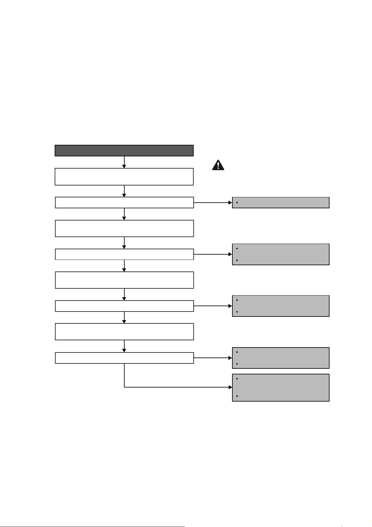
55
15.4 Self-diagnosis Method
15.4.1 H11 (Indoor/Outdoor Abnormal Communication)
Malfunction Decision Conditions
During startup and operation of cooling and heating, the data received from outdoor unit in indoor unit signal
transmission is checked whether it is normal.
Malfunction Caused
Faulty indoor unit PCB.
Faulty outdoor unit PCB.
Indoor unit-outdoor unit signal transmission error due to wiring error.
Indoor unit-outdoor unit signal transmission error due to breaking of wire in the connection wires between the
indoor and outdoor units.
Troubleshooting
When abnormality indication starts again.
For safety reason and to prevent
component breakdown, always switch
off the power before remove and
connect the component.
AC power supply abnormal fluctuation.
Defect in communication circuitry
of outdoor unit PCB.
Replace the PCB.
Improper connection at terminals
indoor/outdoor.
Check indoor/outdoor connecting cable.
Improper connection at terminals
indoor/outdoor.
Check indoor/outdoor connecting cable.
Defect in receiver/transmitter module of
the communication circuitry in indoor
unit PCB.
Replace the indoor unit PCB.
Measure the DC voltage at terminal 2 & 3 (communication
terminals) of outdoor unit terminal board.
Measure the AC voltage at terminal 1 & 2 of indoor unit
terminal board.
Measure the DC voltage at terminal 2 & 3 of indoor unit
terminal board.
YES
YES
YES
YES
NO
NO
NO
NO
Measure the AC voltage at terminal 1 & 2 of outdoor unit
terminal board.
Is the measured voltage 230/240V?
Is the measured DC voltage fluctuate between 10~70V?
Is the measured voltage 230/240V?
Is the measured DC voltage fluctuate between 10~70V?
Caution

56
15.4.2 H12 (Indoor/Outdoor Capacity Rank Mismatched)
Malfunction Decision Conditions
During startup, error code appears when different types of indoor and outdoor units are interconnected.
Malfunction Caused
Wrong models interconnected.
Wrong indoor unit or outdoor unit PCBs mounted.
Indoor unit or outdoor unit PCBs defective.
Indoor-outdoor unit signal transmission error due to wrong wiring.
Indoor-outdoor unit signal transmission error due to breaking of wire 3 in the connection wires between the indoor
and outdoor units.
Troubleshooting
When abnormality indication starts again.
For safety reason and to prevent
component breakdown, always switch
off the power before remove and
connect the component.
Check the indoor and outdoor unit connection wires.
Is there any wiring error?
Check indoor and outdoor units model number.
Is indoor unit and outdoor unit model numbers matched?
Matched compatibility?
Check the spare part numbers of the indoor and outdoor unit
PCBs and compate with their Part Lists.
YES
YES
YES
NO
NO
NO
Correct the indoor-outdoor units connection wires.
Match the compatible model(s).
Change for the specified indoor or outdoor unit
PCB.
Replace the indoor and outdoor unit PCBs.
Caution
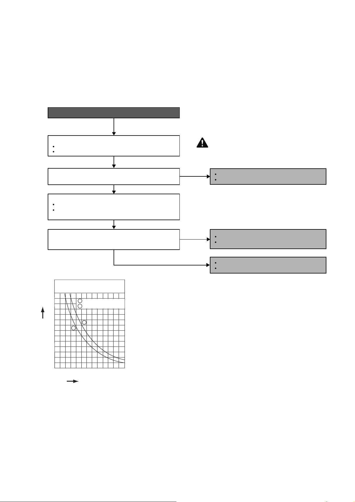
57
15.4.3 H14 (Indoor Intake Air Temperature Sensor Abnormality)
Malfunction Decision Conditions
During startup and operation of cooling and heating, the temperatures detected by the indoor intake air
temperature sensor are used to determine sensor errors.
Malfunction Caused
Faulty connector connection.
Faulty sensor.
Faulty PCB.
Troubleshooting
Check the connector connection:
Turn off the power.
Check the connector connection.
Is the connector connection normal?
When abnormality indication starts again.
For safety reason and to prevent component
breakdown, always switch off the power
before remove and connect the component.
Connector poor contact.
Correct the connection.
Defect in outdoor unit PCB.
Replace the outdoor unit PCB.
Defect in indoor intake air temperature sensor.
Replace the indoor intake air temperature sensor.
Check the indoor intake air temperature sensor:
Plug out connector from the indoor unit PCB.
Measure the resistance of the indoor intake air
temperature sensor.
Is the measured resistance of the indoor intake air
temperature sensor matches the value specified in its
characteristic chart?
NO
NO
YES
YES
Caution
Sensor (Therm istor)
Characteristics
70
60
50
R
e
sist
a
nce
(
kΩ)
T
e
m
p
e
r
a
t
u
r
e
°
F
(
°
C
)
40
30
20
10
14
(-10)
32
(0)
50
(10)
68
(20)
86
(30)
104
(40)
122
(50)
0
1 Pipe temp. Sensor
2 Intake Air Temp. Sensor
1
2
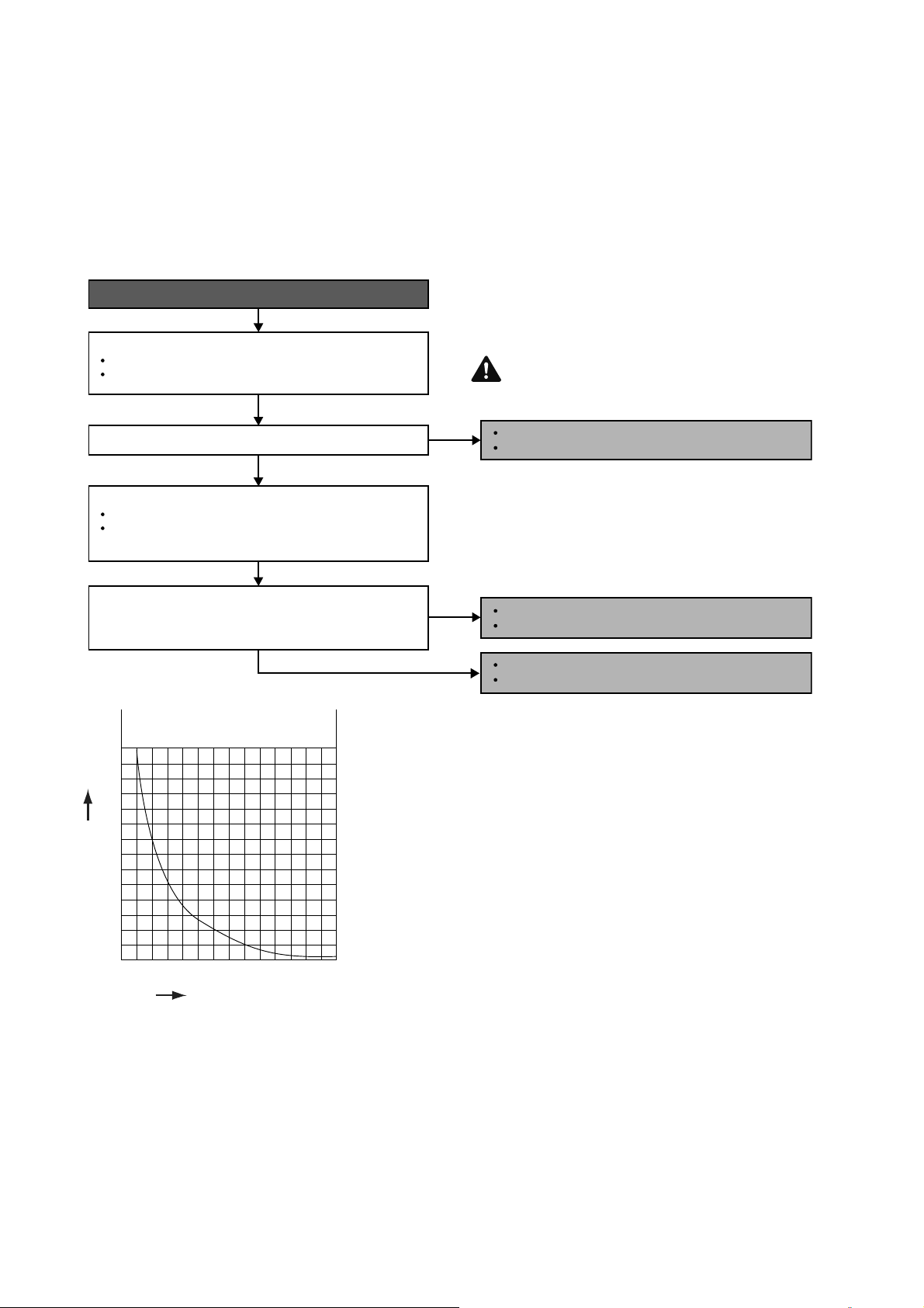
58
15.4.4 H15 (Compressor Temperature Sensor Abnormality)
Malfunction Decision Conditions
During startup and operation of cooling and heating, the temperatures detected by the outdoor compressor
temperature sensor are used to determine sensor errors.
Malfunction Caused
Faulty connector connection.
Faulty sensor.
Faulty PCB.
Troubleshooting
When abnormality indication starts again.
For safety reason and to prevent component
breakdown, always switch off the power
before remove and connect the component.
Connector poor contact.
Correct the connection.
Defect in outdoor compressor temperature sensor.
Replace the outdoor compressor temperature sensor.
Defect in outdoor unit PCB.
Replace the outdoor unit PCB.
Turn off the power.
Check the connector connection.
YES
YES
Check the connector connection:
Plug out connector from the outdoor unit PCB.
Measure the resistance of the outdoor compressor
temperature sensor.
Check the outdoor compressor temperature sensor:
Is the connector connection normal?
Is the measured resistance of the outdoor compressor
temperature sensor matches the value specified in its
characteristic chart?
NO
NO
Caution
Compressor Temp. Sensor
(The rmistor) Chara cteristics
70
60
50
R
esist
a
n
c
e(
k
Ω
)
40
30
20
10
0
68
(20)
104
(40)
140
(60)
176
(80)
212
(100)
248
(120)
284
(140)
Tem
p
e
r
a
tu
r
e°
F
(
°C
)
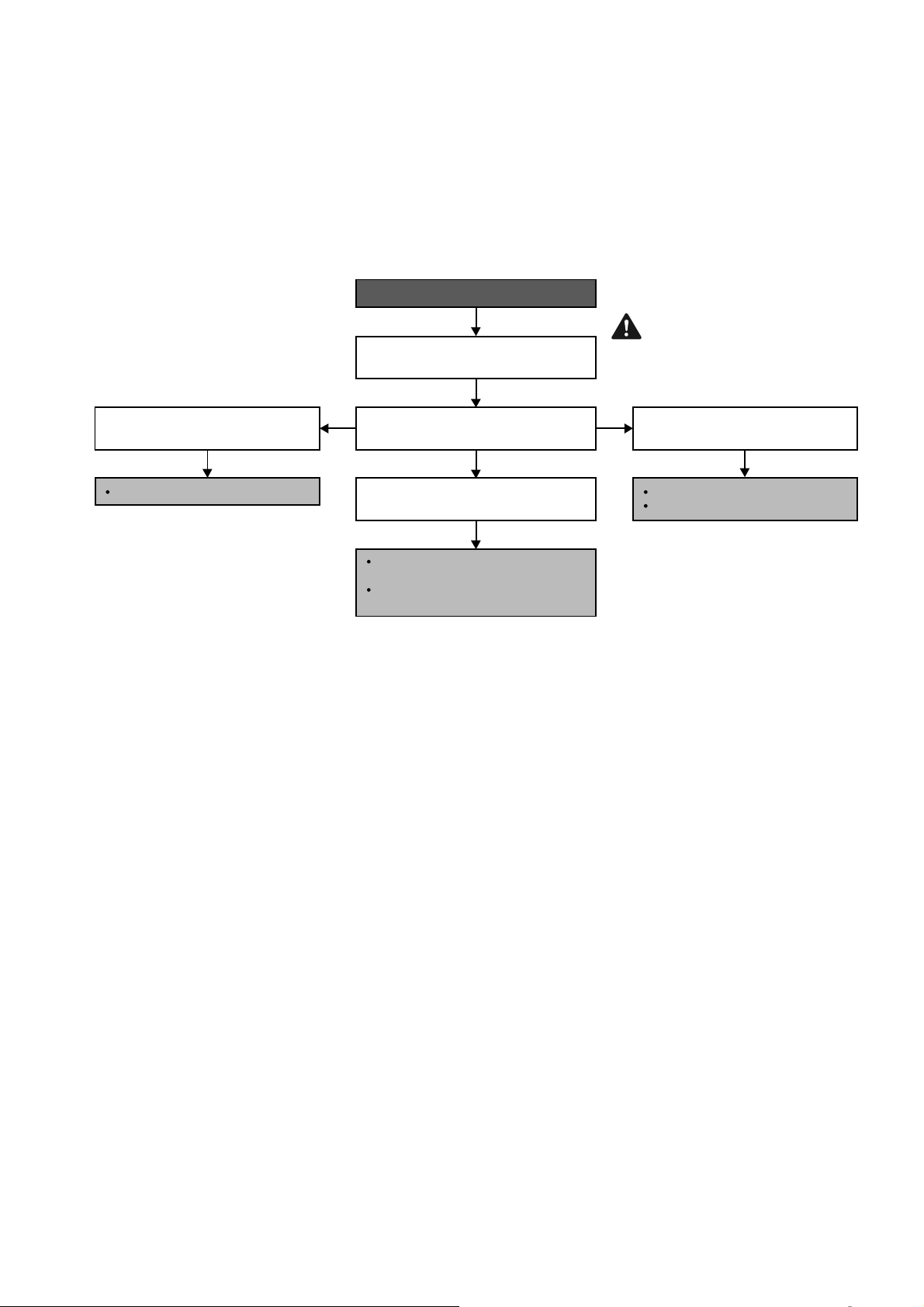
59
15.4.5 H16 (Outdoor Current Transformer)
Malfunction Decision Conditions
An input current, detected by Current Transformer CT, is below threshold value when the compressor is
operating at certain frequency value for 3 minutes.
Malfunction Caused
Lack of gas
Broken CT (current transformer)
Broken Outdoor PCB
Troubleshooting
Refer to Service Manual Technical Graph
for Temp vs Current and Pressure.
Suction pressure and running current is
normal.
Running current is much too low and
suction pressure is much too high.
In forced cooling, check suction pressure
versus running current.
Running current and suction pressure is
very low.
When abnormality indication starts again.
Check for gas leaking source; Repair
or replace defected part(s).
Capillary tube/expansion valve
blockage; Replace defected part(s).
Compressor Lack Compression.
Replace Compressor.
Check & replace defected CT.
For safety reason and to
prevent component
breakdown, always switch off
the power before remove and
connect the component.
Caution
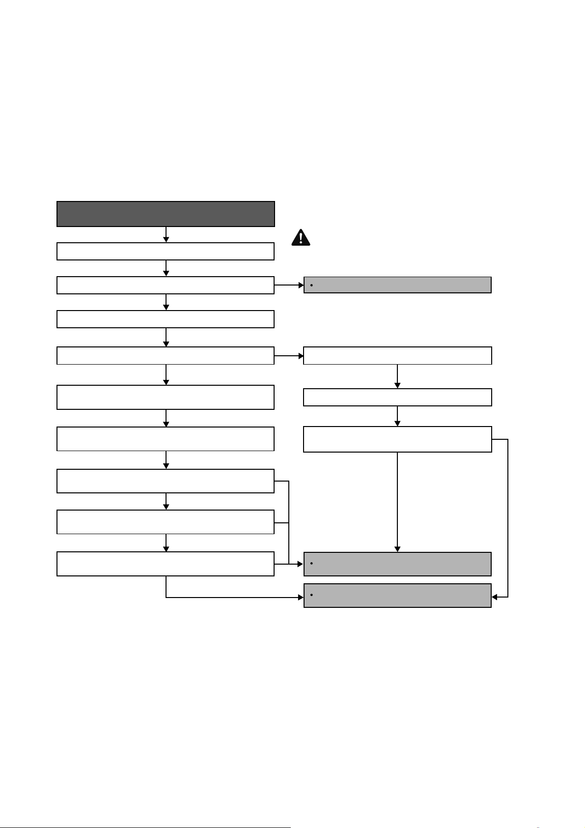
60
15.4.6 H19 (Indoor Fan Motor – DC Motor Mechanism Locked)
Malfunction Decision Conditions
The rotation speed detected by the Hall IC during fan motor operation is used to determine abnormal fan motor
(feedback of rotation > 2550rpm or < 50rpm)
Malfunction Caused
Operation stops due to short circuit inside the fan motor winding.
Operation stops due to breaking of wire inside the fan motor.
Operation stops due to breaking of fan motor lead wires.
Operation stops due to Hall IC malfunction.
Operation error due to faulty indoor unit PCB.
Troubleshooting
Turn off power supply and rotate fan by hand.
When abnormality indication starts again.
Replace fan motor
Does fan rotate smoothly?
Turn power supply on and operate fan.
Does it rotate? Stop fan motor.
Check the rotation feedback output from fan motor.
Rotate the fan motor by hand, is the rotation
feedback voltage 15Vdc (pin 7 & 4) generated?
Turn off power supply and disconnect fan motor connector,
then turn power on.
Check the output of fan motor from indoor PCB.
Is the motor power supply voltage~325Vdc (pin 1 & 4)
generated?
Is the motor control voltage 15Vdc (pin 5 & 4) generated?
Operate the fan, is the rotation command voltage 1~5Vdc
(pin 6 & 4) generated?
NO
NO
NO
NO
NO
NO
YES
YES
YES
YES
For safety reason and to prevent
component breakdown, always switch
off the power before remove and
connect the component.
Replace indoor PCB.
Replace fan motor.
Caution
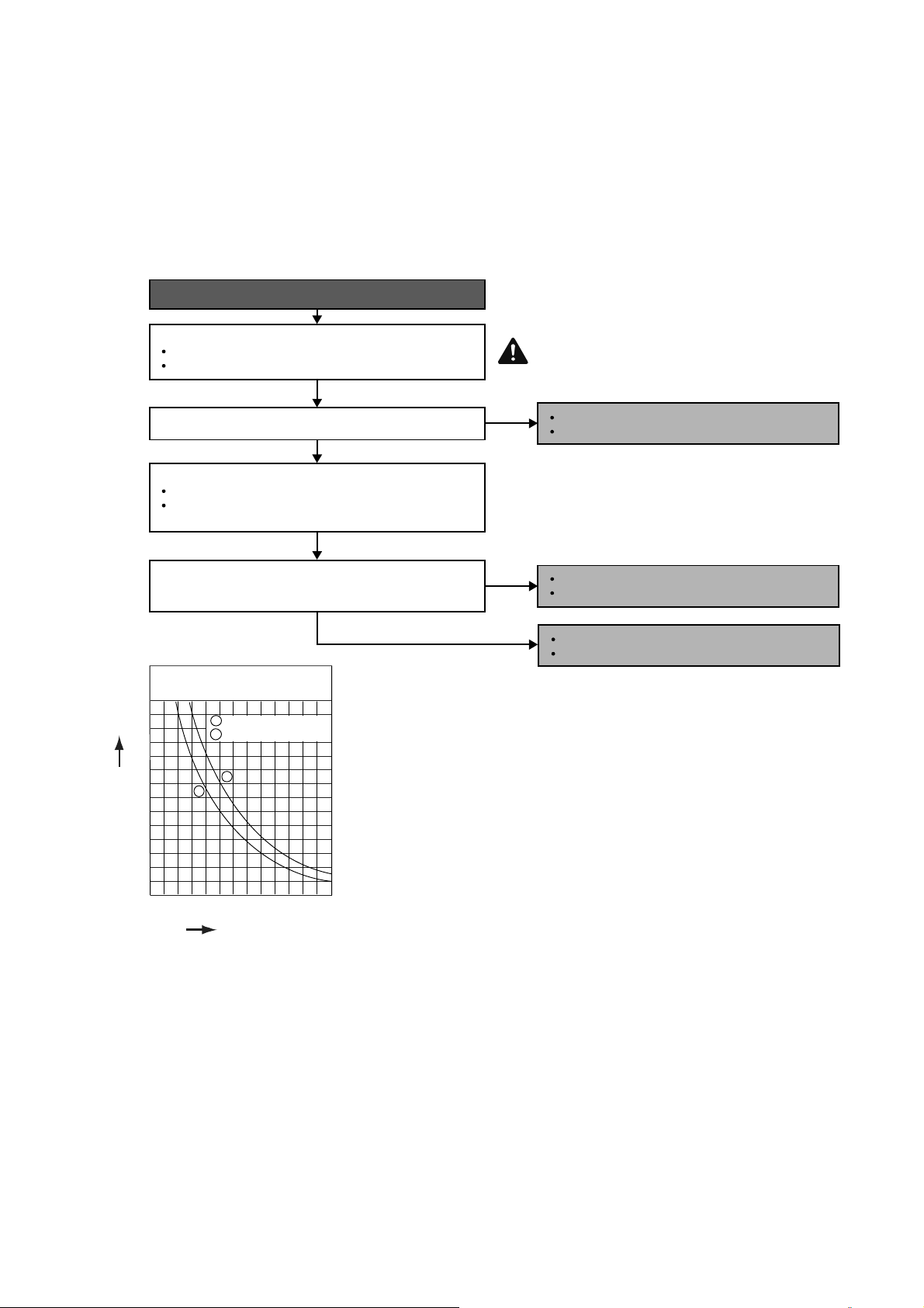
61
15.4.7 H23 / H24 (Indoor Pipe Temperature Sensor Abnormality)
Malfunction Decision Conditions
During startup and operation of cooling and heating, the temperatures detected by the indoor heat exchanger
temperature sensor are used to determine sensor errors.
Malfunction Caused
Faulty connector connection.
Faulty sensor.
Faulty PCB.
Troubleshooting
When abnormality indication starts again.
For safety reason and to prevent component
breakdown, always switch off the power
before remove and connect the component.
Connector poor contact.
Correct the connection.
Defect in outdoor unit PCB.
Replace the outdoor unit PCB.
Defect in outdoor intake air temperature sensor.
Replace the outdoor air temperature sensor.
NO
NO
YES
YES
Check the connector connection:
Turn off the power.
Is the connector connection normal?
Check the connector connection.
Check the outdoor air temperature sensor:
Is the measured resistance of the outdoor air temperature
sensor matches the value specified in its characteristic
chart?
Plug out connector from the outdoor unit PCB.
Measure the resistance of the outdoor air temperature
sensor.
Caution
Sensor (T herm istor)
Characteristics
70
60
50
R
e
s
i
s
t
a
n
ce
(
k
Ω)
40
30
20
10
0
1 Pipe temp. Sensor
2 Intake Air Temp. Sensor
1
2
14
(-10)
32
(0)
50
(10)
68
(20)
86
(30)
104
(40)
122
(50)
Temperature °F (°C)
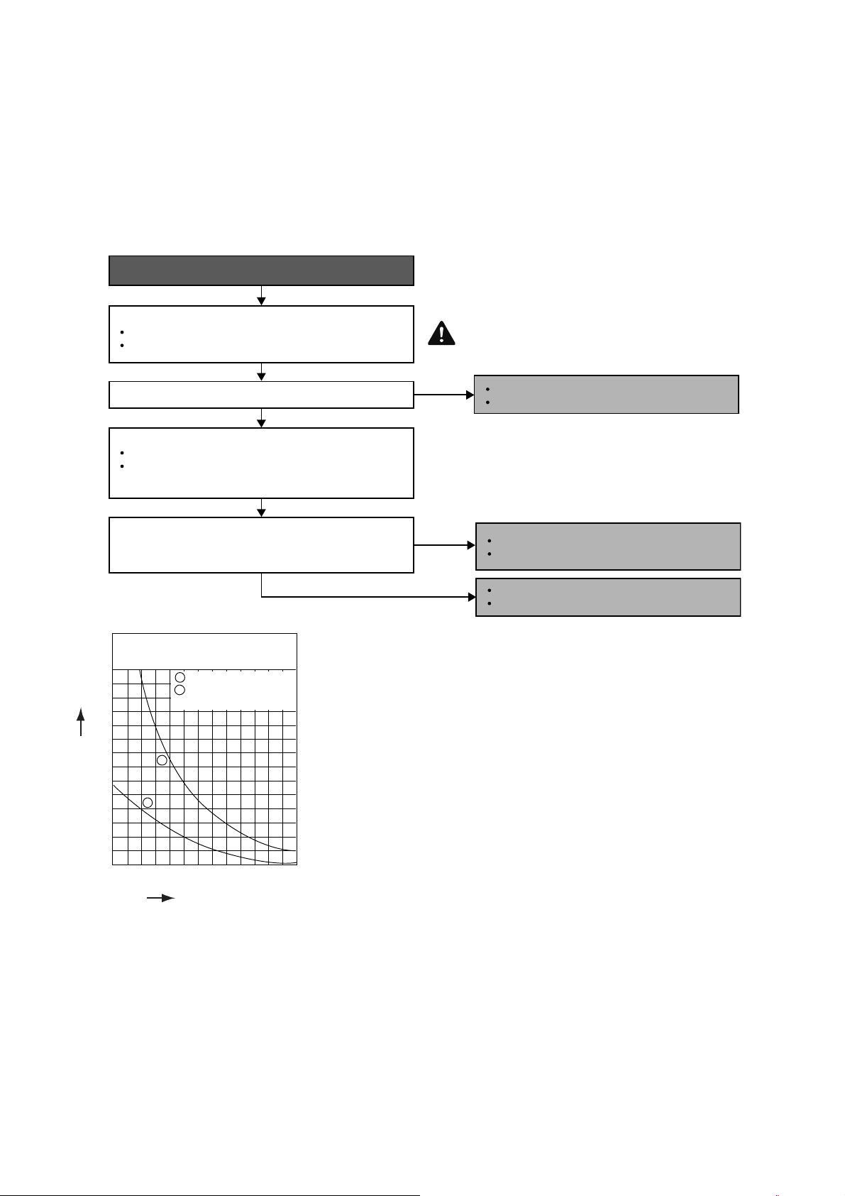
62
15.4.8 H27 (Outdoor Air Temperature Sensor Abnormality)
Malfunction Decision Conditions
During startup and operation of cooling and heating, the temperatures detected by the outdoor air temperature
sensor are used to determine sensor errors.
Malfunction Caused
Faulty connector connection.
Faulty sensor.
Faulty PCB.
Troubleshooting
Check the connector connection:
Is the measured resistance of the outdoor air temperature
sensor matches the value specified in its characteristic
chart?
Is the connector connection normal?
When abnormality indication starts again.
For safety reason and to prevent component
breakdown, always switch off the power
before remove and connect the component.
Turn off the power.
Check the connector connection.
Defect in outdoor air temperature sensor.
Replace the outdoor air temperature sensor.
Defect in outdoor unit PCB.
Replace the outdoor unit PCB.
NO
NO
YES
YES
Check the outdoor air temperature sensor:
Plug out connector from the outdoor unit PCB.
Measure the resistance of the outdoor air temperature
sensor.
Connector poor contact.
Correct the connection.
Caution
Sensor (T herm istor)
Characteristics
70
60
50
R
e
sist
a
n
ce
(
kΩ)
40
30
20
10
0
1 Outdoor Air Sensor
2 Outdoor Heat Exchanger
Sensor
1
2
14
(-10)
32
(0)
50
(10)
68
(20)
86
(30)
104
(40)
122
(50)
T
e
m
p
e
r
a
t
u
r
e
°
F
(
°
C
)
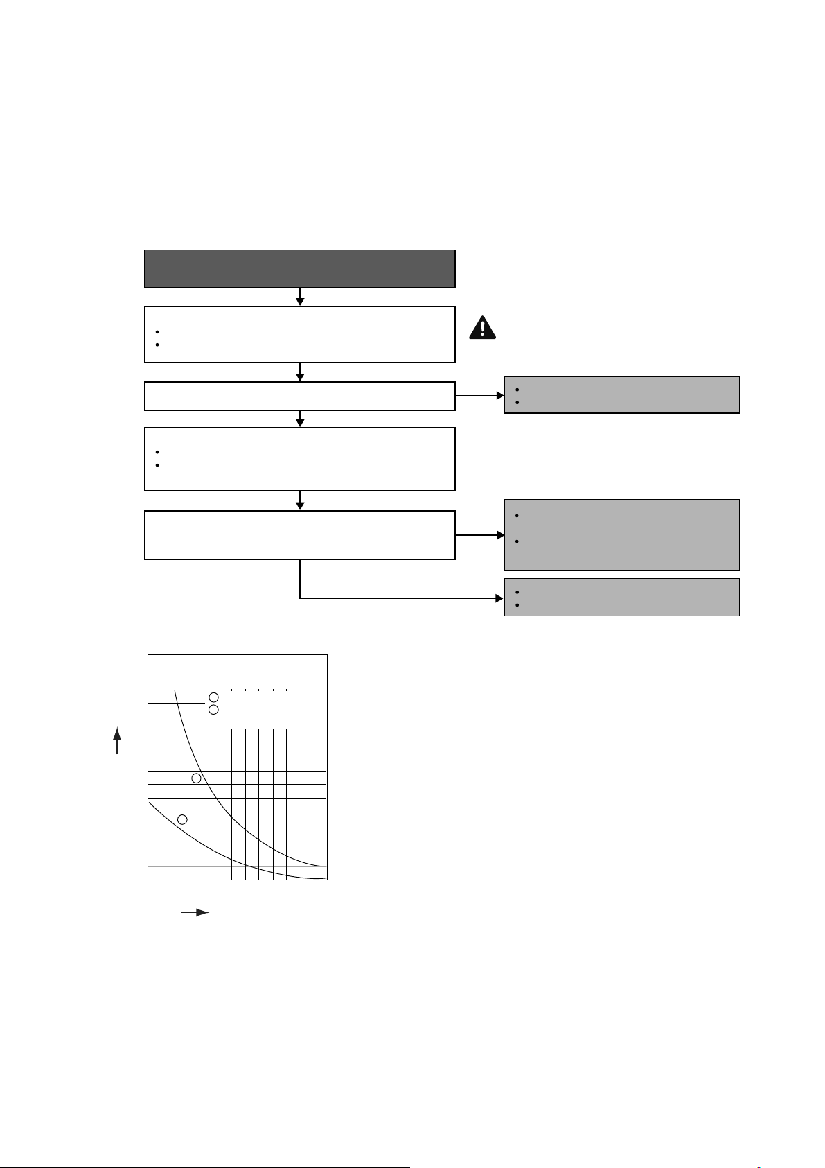
63
15.4.9 H28 (Outdoor Pipe Temperature Sensor Abnormality)
Malfunction Decision Conditions
During startup and operation of cooling and heating, the temperatures detected by the outdoor pipe temperature
sensor are used to determine sensor errors.
Malfunction Caused
Faulty connector connection.
Faulty sensor.
Faulty PCB.
Troubleshooting
Is the measured resistance of the outdoor heat exchanger
temperature sensor matches the value specified in its
characteristic chart?
Is the connector connection normal?
When abnormality indication starts again.
For safety reason and to prevent
component breakdown, always switch
off the power before remove and
connect the component.
No
No
YES
YES
Check the outdoor heat exchanger temperature sensor:
Plug out connector from the outdoor unit PCB.
Measure the resistance of the outdoor heat exchanger
temperature sensor.
Check the connector connection:
Turn off the power.
Check the connector connection.
Connector poor contact.
Correct the connection.
Defect in outdoor unit PCB.
Replace the outdoor unit PCB.
Defect in outdoor heat exchanger
temperature sensor.
Replace the outdoor heat exchanger
temperature sensor.
Caution
Sensor (T he rm istor)
Characteristics
70
60
50
R
e
s
i
s
t
a
n
ce
(
k
Ω)
40
30
20
10
0
1 Outdoor Air Sensor
2 Outdoor Heat Exchanger
Sensor
1
2
14
(-10)
32
(0)
50
(10)
68
(20)
86
(30)
104
(40)
122
(50)
T
e
m
p
e
r
a
t
u
r
e
°
F
(
°
C
)
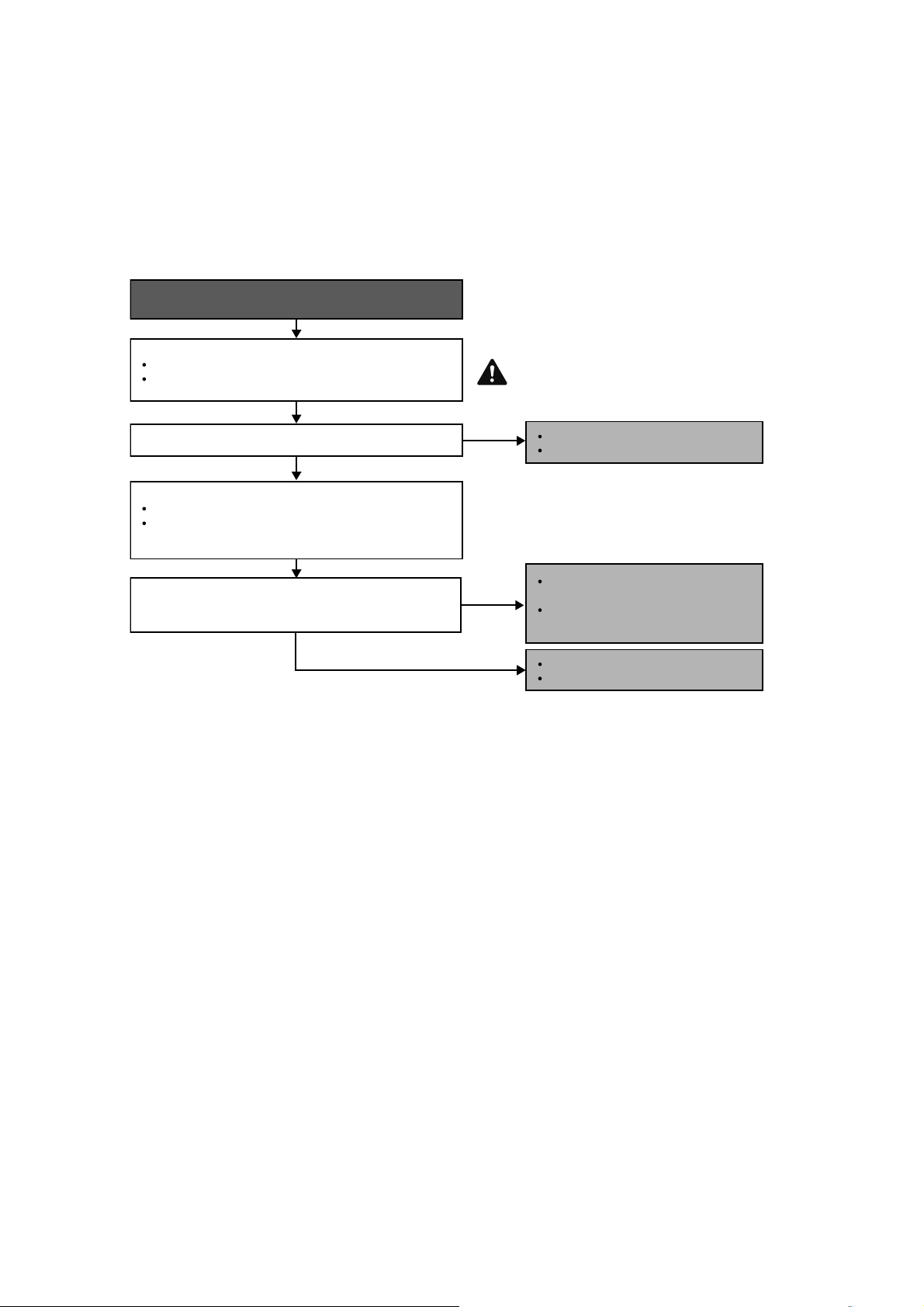
64
15.4.10 H30 (Compressor Discharge Temperature Sensor Abnormality)
Malfunction Decision Conditions
During startup and operation of cooling and heating, the temperatures detected by the outdoor discharge pipe
temperature sensor are used to determine sensor errors.
Malfunction Caused
Faulty connector connection.
Faulty sensor.
Faulty PCB.
Troubleshooting
When abnormality indication starts again.
For safety reason and to prevent
component breakdown, always switch
off the power before remove and
connect the component.
Is the measured resistance of the outdoor discharge pipe
temperature sensor matches the value specified in its
characteristic chart?
Is the connector connection normal?
YES
YES
Check the outdoor discharge pipe temperature sensor:
Plug out connector from the outdoor unit PCB.
Measure the resistance of the outdoor discharge pipe
temperature sensor.
Check the connector connection:
Turn off the power.
Check the connector connection.
Connector poor contact.
Correct the connection.
Defect in outdoor unit PCB.
Replace the outdoor unit PCB.
Defect in outdoor discharge pipe
temperature sensor.
Replace the outdoor discharge pipe
temperature sensor.
NO
NO
Caution
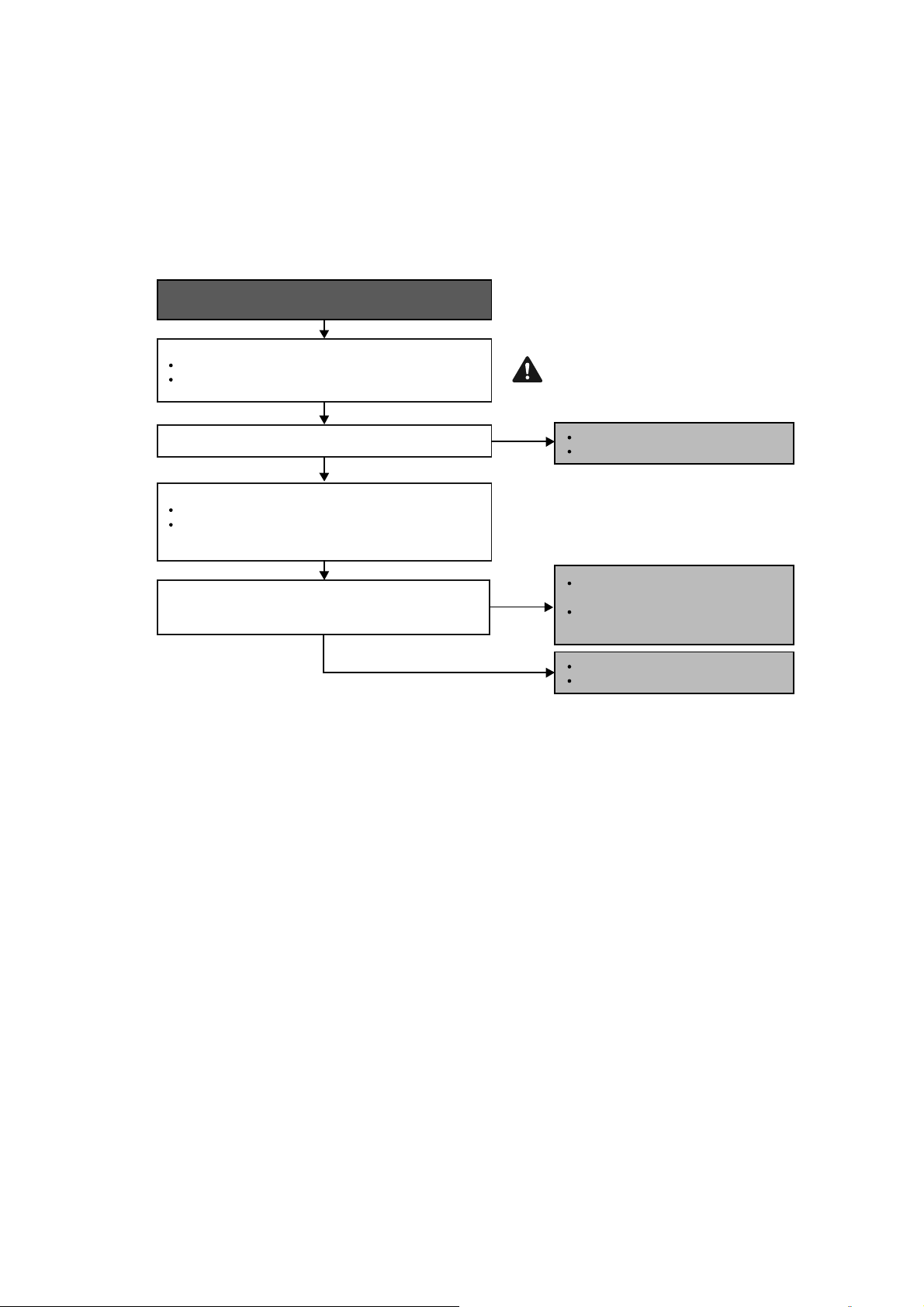
65
15.4.11 H32 (Outdoor Heat Exchanger Temperature Sensor 2 Abnormality)
Malfunction Decision Conditions
During startup and operation of cooling and heating, the temperatures detected by the outdoor heat exchanger
temperature sensor are used to determine sensor errors.
Malfunction Caused
Faulty connector connection.
Faulty sensor.
Faulty PCB.
Troubleshooting
When abnormality indication starts again.
For safety reason and to prevent
component breakdown, always switch
off the power before remove and
connect the component.
Is the measured resistance of the outdoor heat exchanger
temperature sensor matches the value specified in its
characteristic chart?
Is the connector connection normal?
YES
YES
Check the outdoor discharge pipe temperature sensor:
Plug out connector from the outdoor unit PCB.
Measure the resistance of the outdoor discharge pipe
temperature sensor.
Check the connector connection:
Turn off the power.
Check the connector connection.
Connector poor contact.
Correct the connection.
Defect in outdoor unit PCB.
Replace the outdoor unit PCB.
Defect in outdoor discharge pipe
temperature sensor.
Replace the outdoor discharge pipe
temperature sensor.
NO
NO
Caution
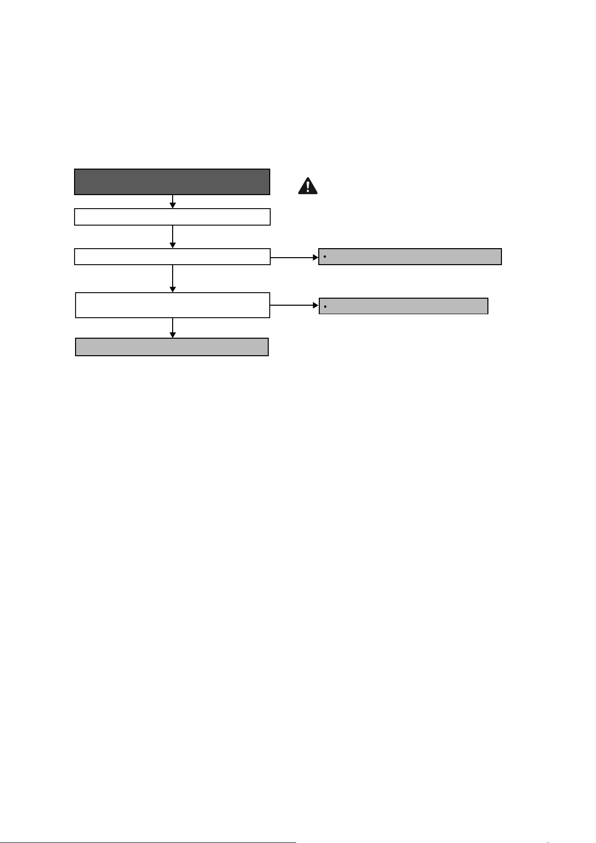
66
15.4.12 H33 (Unspecified Voltage between Indoor and Outdoor)
Malfunction Decision Conditions
The supply power is detected for its requirement by the indoor/outdoor transmission.
Malfunction Caused
Wrong models interconnected.
Wrong indoor unit and outdoor unit PCBs used.
Indoor unit or outdoor unit PCB defective.
Troubleshooting
When abnormality indication starts again.
For safety reason and to prevent
component breakdown, always switch
off the power before remove and
connect the component.
Match the compatible model (follow specification).
Replace the indoor and outdoor unit PCB.
Change for the specified indoor or outdoor unit PCB.
Check indoor and outdoor units model number.
Check indoor and outdoor PCB part number and
compare if they matched part list.
Is the indoor and outdoor unit model number matched?
NO
NO
YES
Caution
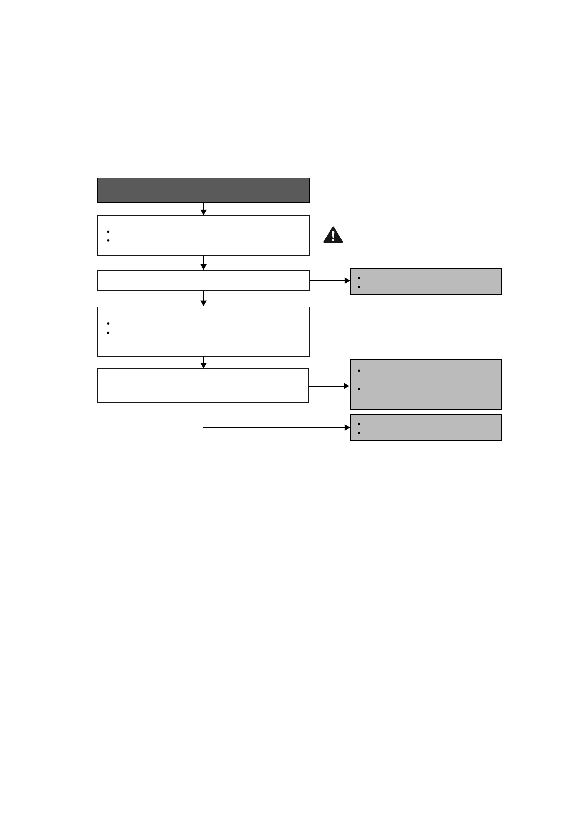
67
15.4.13 H36 (Outdoor Gas Pipe Sensor Abnormality)
Malfunction Decision Conditions
During startup and operation of cooling and heating, the temperatures detected by the outdoor gas pipe
temperature sensor are used to determine sensor errors.
Malfunction Caused
Faulty connector connection.
Faulty sensor.
Faulty PCB.
Troubleshooting
When abnormality indication starts again.
For safety reason and to prevent
component breakdown, always switch
off the power before remove and
connect the component.
Is the measured resistance of the outdoor gas pipe
temperature sensor matches the value specified in its
characteristic chart?
Is the connector connection normal?
YES
YES
Check the outdoor discharge pipe temperature sensor:
Plug out connector from the outdoor unit PCB.
Measure the resistance of the outdoor discharge pipe
temperature sensor.
Check the connector connection:
Turn off the power.
Check the connector connection.
Connector poor contact.
Correct the connection.
Defect in outdoor unit PCB.
Replace the outdoor unit PCB.
Defect in outdoor discharge pipe
temperature sensor.
Replace the outdoor discharge pipe
temperature sensor.
NO
NO
Caution
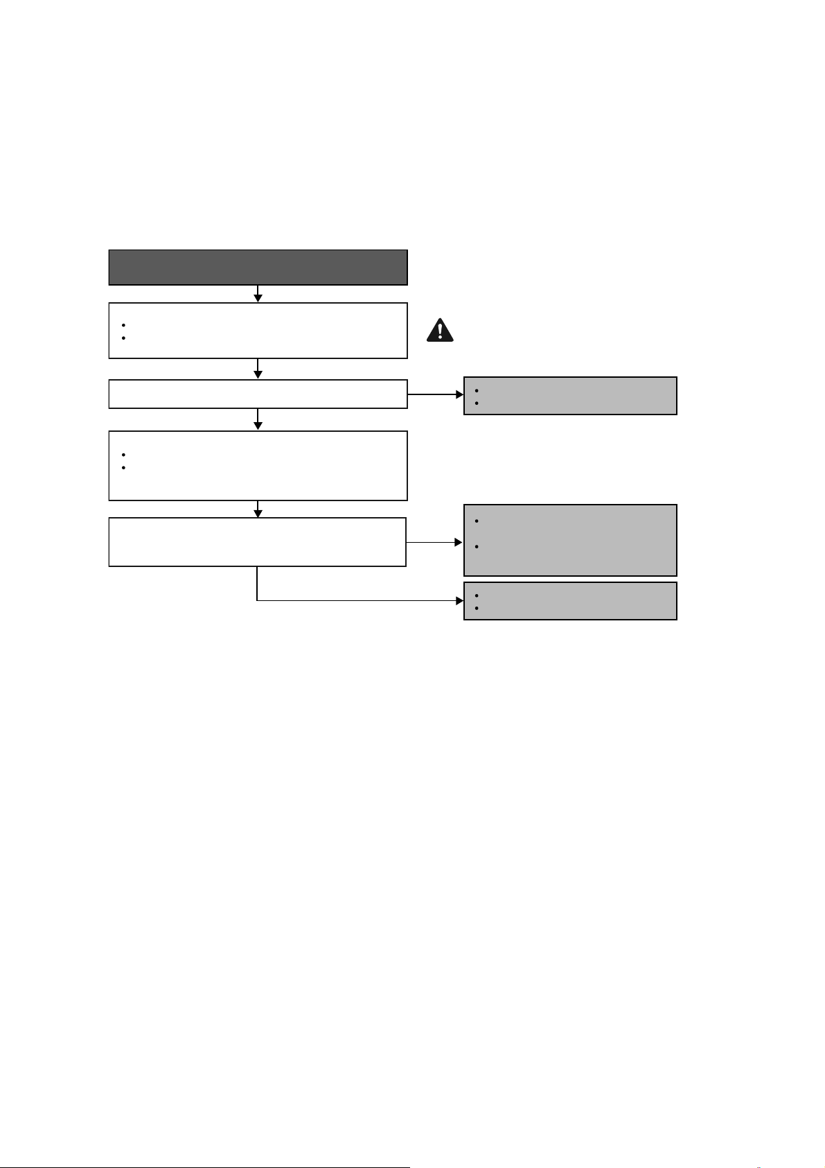
68
15.4.14 H37 (Outdoor Liquid Pipe Temperature Sensor Abnormality)
Malfunction Decision Conditions
During startup and operation of cooling and heating, the temperatures detected by the outdoor liquid pipe
temperature sensor are used to determine sensor errors.
Malfunction Caused
Faulty connector connection.
Faulty sensor.
Faulty PCB.
Troubleshooting
When abnormality indication starts again.
For safety reason and to prevent
component breakdown, always switch
off the power before remove and
connect the component.
Is the measured resistance of the outdoor liquid pipe
temperature sensor matches the value specified in its
characteristic chart?
Is the connector connection normal?
YES
YES
Check the outdoor discharge pipe temperature sensor:
Plug out connector from the outdoor unit PCB.
Measure the resistance of the outdoor discharge pipe
temperature sensor.
Check the connector connection:
Turn off the power.
Check the connector connection.
Connector poor contact.
Correct the connection.
Defect in outdoor unit PCB.
Replace the outdoor unit PCB.
Defect in outdoor discharge pipe
temperature sensor.
Replace the outdoor discharge pipe
temperature sensor.
NO
NO
Caution
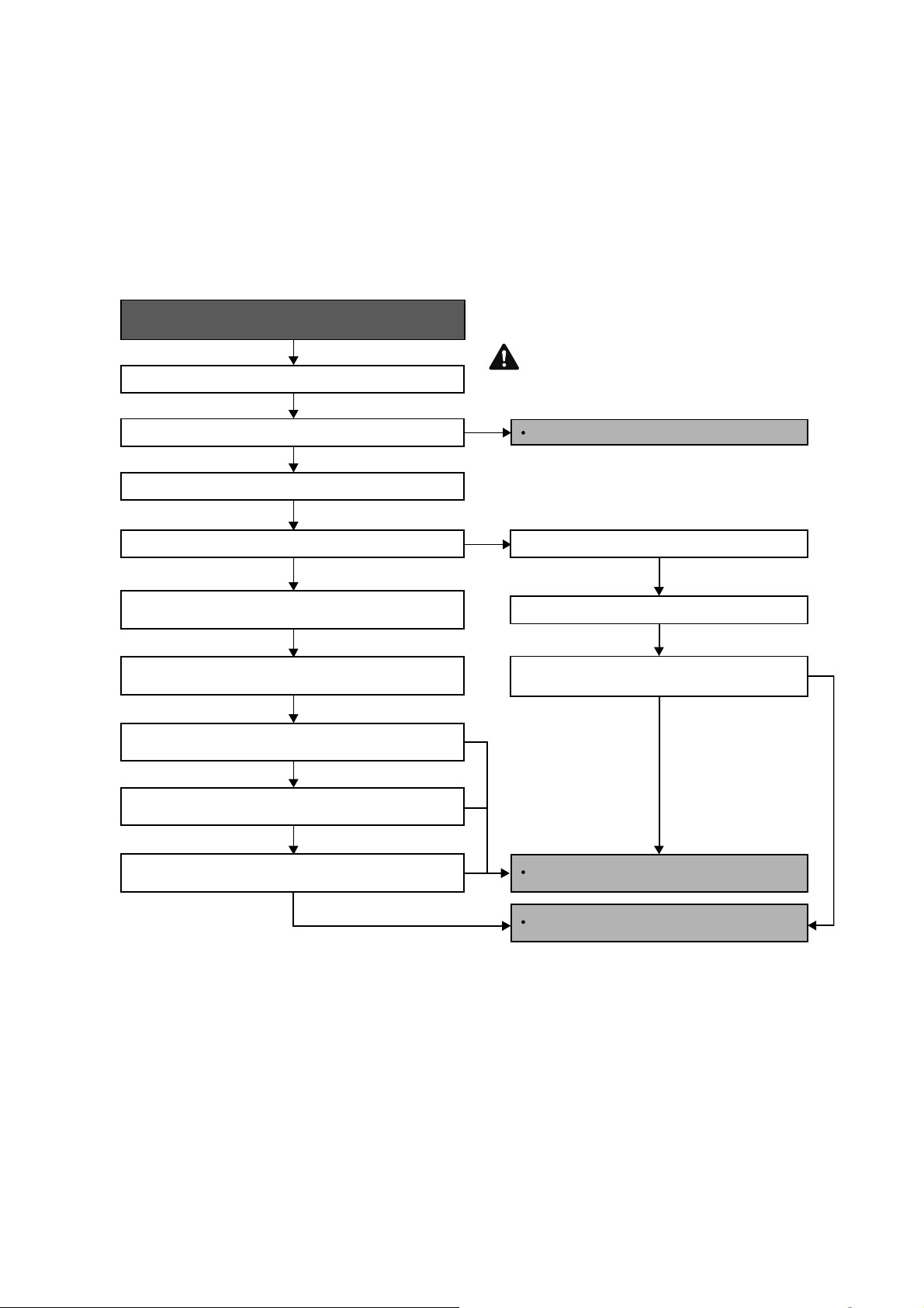
69
15.4.15 H97 (Outdoor Fan Motor – DC Motor Mechanism Locked)
Malfunction Decision Conditions
The rotation speed detected by the Hall IC during fan motor operation is used to determine abnormal fan motor.
Malfunction Caused
Operation stops due to short circuit inside the fan motor winding.
Operation stops due to breaking of wire inside the fan motor.
Operation stops due to breaking of fan motor lead wires.
Operation stops due to Hall IC malfunction.
Operation error due to faulty outdoor unit PCB.
Troubleshooting
Turn off power supply and rotate fan by hand.
When abnormality indication starts again.
Replace fan motor.
Does fan rotate smoothly?
Turn power supply on and operate fan.
Does it rotate? Stop fan motor.
Check the rotation feedback output from fan motor.
Rotate the fan motor by hand, is the rotation
feedback voltage 15Vdc (pin 1 & 4) generated?
Turn off power supply and disconnect fan motor connector,
then turn power on.
Check the output of fan motor from indoor PCB.
Is the motor power supply voltage~325Vdc (pin 7 & 4)
generated?
Is the motor control voltage 15Vdc (pin 3 & 4) generated?
Operate the fan, is the rotation command voltage 1~5Vdc
(pin 2 & 4) generated?
NO
NO
NO
NO
NO
NO
YES
YES
YES
YES
For safety reason and to prevent
component breakdown,always switch
off the power before remove and
connect the component.
Replace indoor PCB.
Replace fan motor.
Caution
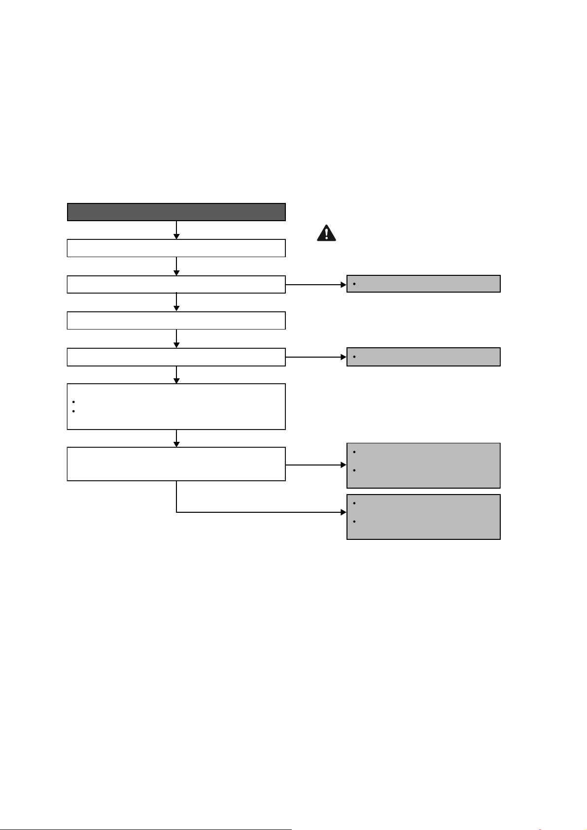
70
15.4.16 H98 (Error Code Stored in Memory and no alarm is triggered / no TIMER LED
flashing)
Malfunction Decision Conditions
Indoor high pressure is detected when indoor heat exchanger is detecting very high temperature when the unit is
operating in heating operation.
Phenomena: unit is stopping and re-starting very often in heating mode
Malfunction Caused
Indoor heat exchanger thermistor
Clogged air filter or heat exchanger
Over-bent pipe (liquid side)
Troubleshooting
Check the indoor unit intake air filter.
When abnormality indication starts again.
For safety reason and to prevent
component breakdown, always switch
off the power before remove and
connect the component.
Clean the air filter.
Is the air filter dirty?
Check the dust accumulation on the indoor unit heat exchanger.
Is the indoor unit heat exchanger dirty?
Is the measured resistance of the indoor pipe temperature
thermistor matches the value specified in its characteristic
chart?
Check the indoor pipe temperature thermistor:
Plug out connector (CN-TH) from the indoor unit PCB.
Measure the resistance of the indoor heat exchanger
temperature thermistor.
Clean the indoor unit heat exchanger
YES
NO
NO
Clean the indoor unit heat exchanger.
Defect in indoor pipe temperature
thermistor.
Replace the indoor pipe temperature
thermistor.
YES
YES
NO
Check the piping & installation
condition.
Replace piping / reinstall the unit if
necessary.
Caution
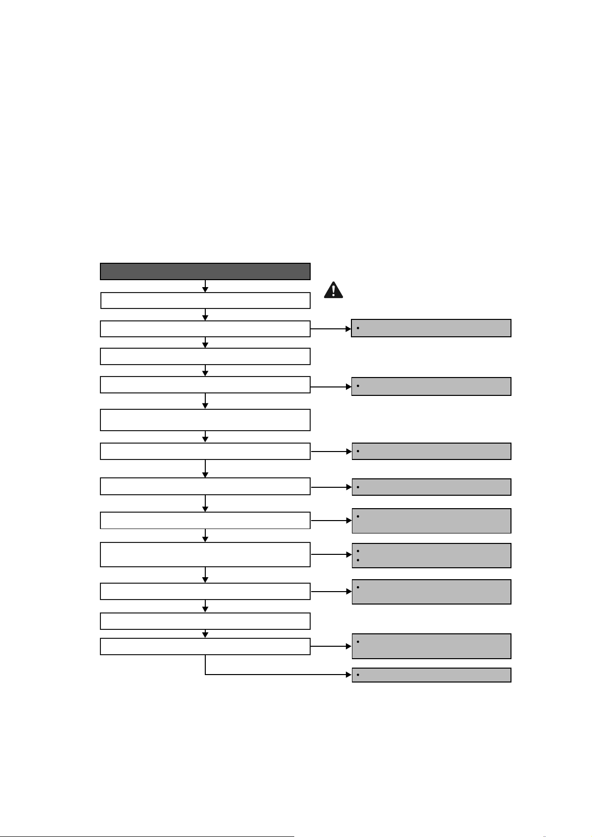
71
15.4.17 H99 (Indoor Freeze Prevention Protection: Cooling or Soft Dry)
Error Code will not display (no Timer LED blinking) but store in EEPROM
Malfunction Decision Conditions
Freeze prevention control takes place (when indoor pipe temperature is lower than 35.6°F (2°C))
Malfunction Caused
Air short circuit at indoor unit
Clogged indoor unit air filter
Dust accumulation on the indoor unit heat exchanger
2/3 way valve closed
Faulty indoor unit fan motor
Refrigerant shortage (refrigerant leakage)
Clogged expansion valve or strainer
Faulty indoor pipe temperature sensor
Faulty indoor unit PCB
Troubleshooting
When abnormality indication starts again.
Check the air passage.
YES
Provide sufficient air passage.
YES
Clean the air filter.
For safety reason and to prevent
component breakdown, always switch
off the power before remove and
connect the component.
Is there any short circuit?
Check the indoor unit air filter.
Is the air filter dirty?
Check the dust accumulation on the indoor unit heat
exchanger.
Is the indoor unit heat exchanger dirty?
Check if 2/3 way valve is closed?
Check if indoor fan motor operated normally?
Check if expansion valve or strainer clogged (ice formed)?
Check the indoor pipe temperature sensor.
Does it conform to the sensor characteristic chart?
Check for gas leakage. Is Oil oozing out from the 2/3 way
valve?
YES
YES
YES
YES
NO
Clean the indoor unit heat exchanger.
Open the 2/3 way valve.
Replace the indoor unit fan motor and/or
indoor unit PCB.
Reclaim and recharge with correct amount
of refrigerant.
Replace the indoor pipe temperature
sensor.
Replace the indoor unit PCB.
Repair the pipe flare or union nuts.
Reclaim and recharge refrigerant.
NO
YES
Caution
NO
NO
NO
NO
YES
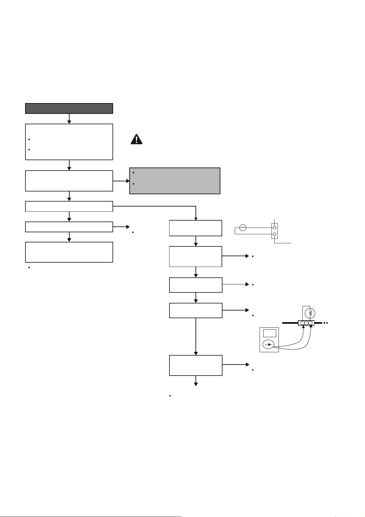
72
15.4.18 F11 (4-way Valve Switching Failure)
Malfunction Decision Conditions
When indoor heat exchanger is cold during heating (except deice) or when indoor heat exchanger is hot during
cooling and compressor operating, the 4-way valve is detected as malfunction.
Malfunction Caused
Indoor heat exchanger (pipe) thermistor
4-way valve malfunction
Troubleshooting
* Check gas side pipe – for hot gas flow in cooling mode
For safety reason and to prevent component
breakdown, always switch off the power before
remove and connect the component.
When abnormality starts again.
Check the indoor pipe temperature
thermistor:
Plug out connector (CN-TH) from the
indoor unit PCB.
Replace
Outdoor PCB
Measure the resistance of the indoor heat
exchanger temperature thermistor.
Check connecting tubes to 4-way valve
Is the measured resistance of the indoor
pipe temperature thermistor matches the
value specified in its characteristic chart?
The 4-way valve may have been damaged or
wrongly connected between discharge and
suction tube.
Problem occurs in heating mode only?
Is 4-way solenaid valve being energised?
Defect in indoor pipe temperature
thermistor.
Replace the indoor pipe temperature
thermistor.
4-way valve not working
(not energize).
Check CN-HOT
connection
(4-way valve connector).
Check V-coil attach to
solenoid valve.
Check valve v-coil
continuity.
Measure voltage
supplied to CN-HOT at
the start of heating.
YES
OK
No
Good
4 WAYS VALVE
COIL COMPLETE
YELLOW
CN-HOT
(WHT)
1
2
YELLOW
No
Good
No
continuity
(open)
OK
OK
No supply
YES
Outdoor PCB fault
Reserve solenoid valve faulty
Replace Outdoor PCB
Replace the 4-way valve
Remove CN-HOT.
Measure continuity
of the coil.
Reconnect CN-HOT
(4-way valve connector).
Attach and screw the V-coil
to solenoid valve.
Replace
V-coil only
V-coil fault
CN-HOT
4WAYS
VALVE
(VH9-2)
Outdoor PCB fault
YES
NO
NO
NO, it happen in cooling/dry as well.
OK (Depending on 4-way valve model)
123
Caution
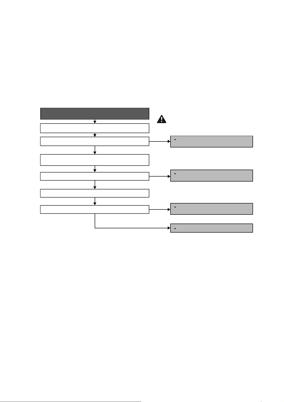
73
15.4.19 F17 (Indoor Standby Units Freezing Abnormality)
Malfunction Decision Conditions
When the different between indoor intake air temperature and indoor pipe temperature is above 50°F (10°C) or
indoor pipe temperature is below 30.2°F (-1.0°C).
Remark:
When the indoor standby unit is freezing, the outdoor unit transfers F17 error code to the corresponding indoor
unit and H39 to other indoor unit(s).
Malfunction Caused
Wrong wiring connection
Faulty sensor
Faulty expansion valve
Troubleshooting
When F17 indication happens.
For safety reason and to prevent
component breakdown, always switch
off the power before remove and
connect the component.
Check the system wiring connection.
Is the wiring connection ok?
Check the indoor intake air and indoor pipe temperature
sensors.
Does it conform to the sensor characteristic chart?
Check the expansion valve.
Is the expansion valve ok?
Perform Auto Wiring to correct the wiring
connection.
Replace the indoor intake air or indoor pipe
temperature sensor.
Replace the solenoid coil or expansion
valve.
Replace outdoor unit PCB.
NO
NO
NO
YES
YES
YES
Caution
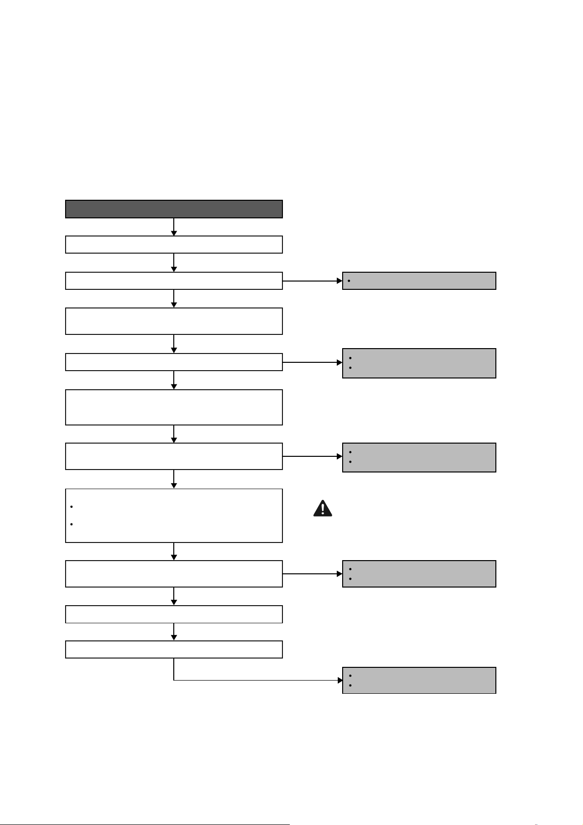
74
15.4.20 F90 (Power Factor Correction Protection)
Malfunction Decision Conditions
To maintain DC voltage level supply to power transistor.
To detect high DC voltage level after rectification.
Malfunction Caused
During startup and operation of cooling and heating, when Power Factor Correction (PFC) protection circuitry at
the outdoor unit main PCB senses abnormal DC voltage level for power transistors.
When DC voltage detected is LOW, transistor switching will turn ON by controller to push-up the DC level.
When DC voltage detected is HIGH (391Vdc – 425Vdc), active LOW signal will send by the controller to turn OFF
relay RY-C.
Troubleshooting
When abnormality indication starts again.
YES
NO (391.2Vdc ~ 425Vdc)
YES
YES
NO
NO
NO
For safety reason and to prevent
component breakdown, always switch
off the power before remove and
connect the component.
Replace the outdoor unit PCB.
Defect in PFC circuitry.
Replace outdoor fan motor.
Defect in outdoor fan motor.
Replace compressor.
Defect in compressor.
Replace reactor.
Defect in reactor.
AC power supply abnormal surge.
Reset the error code and turn on the unit again.
Is AC power supply normal fluctuation?
Is the DC voltage between DCP(+) and DCN(-) normal?
Check the reactor impedance.
Is the impedance of the reactor low?
Verify PFC abnormality by measuring DC voltage between
DCP(+) and DCN(-) at the capacitor PCB.
Is the DC voltage between CN-FM1 and 4 of the outdoor fan
motor normal?
Are the compressor’s winding resistance (U-V, V-W, U-W)
uniform?
Confirm the DC voltage between CN-FM 1 and 4 when
compressor is running. Normal voltage range should be
between 265-325Vdc.
Turn off the power and disconnect the harnesses U, V,
and W.
Check the compressor winding resistance:
Measure the winding resistance between U-V, V-W and
W-U.
YES (~280Vdc)
Caution

75
15.4.21 F91 (Refrigeration Cycle Abnormality)
Malfunction Decision Conditions
The input current is low while the compressor is running at higher than the setting frequency.
Malfunction Caused
Lack of gas.
3-way valve close.
Troubleshooting
When F91 indication happens.
For safety reason and to prevent
component breakdown, always switch
off the power before remove and
connect the component.
Check for gas leaking source;
Repair or replace defected part(s).
Re-claim and then re-charge the right
amount.
YES
YES
NO, closed
NO, gas amount is OK
Check 3 way valve.
Check for gas leaking source (Refer to H16).
Gas leaking?
Check other parts in refrigeration cycles.
3-way valve opened?
Open 3 way valve.
Caution
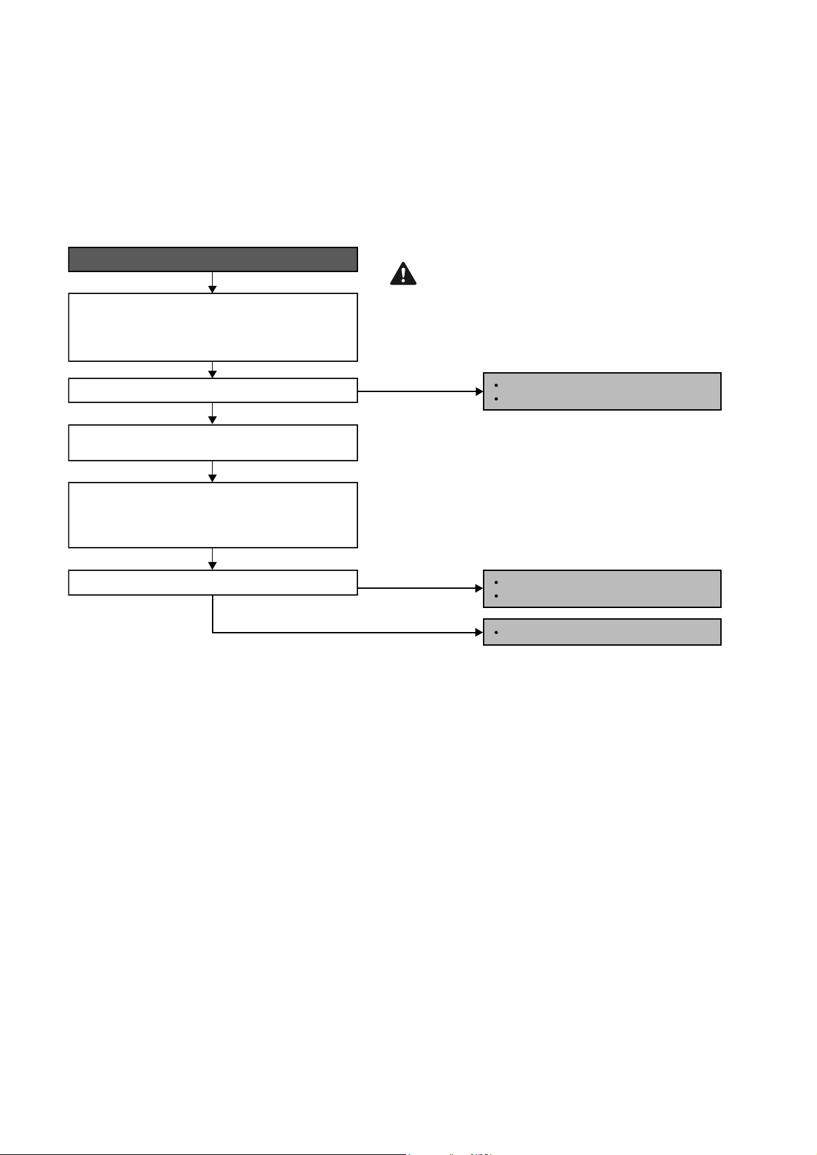
76
15.4.22 F93 (Compressor Rotation Failure)
Malfunction Decision Conditions
A compressor rotation failure is detected by checking the compressor running condition through the position
detection circuit.
Malfunction Caused
Compressor terminal disconnect
Faulty Outdoor PCB
Faulty compressor
Troubleshooting
When F93 indication happens.
For safety reason and to prevent component
breakdown, always switch off the power
before remove and connect the component.
YES
YES
NO
NO
Connector poor contact.
Correct the connection.
IPM defective.
Replace compressor.
Replace outdoor unit PCB.
Check the U, V and W connector connection:
- Turn OFF the power.
- Check the U, V and W connector connection at outdoor
PCB and compressor terminal.
Is the connector connection normal?
Disconnect the harnesses U, V and W from the
compressor terminal.
Is the blinking of the 6 LEDs in same sequence/condition?
From the disconnected harnesses U, V and W, connect
them to the inverter checker. Turn ON the power and
operate the system. Check the inverter checker 6 LEDs
blinking condition.
Caution
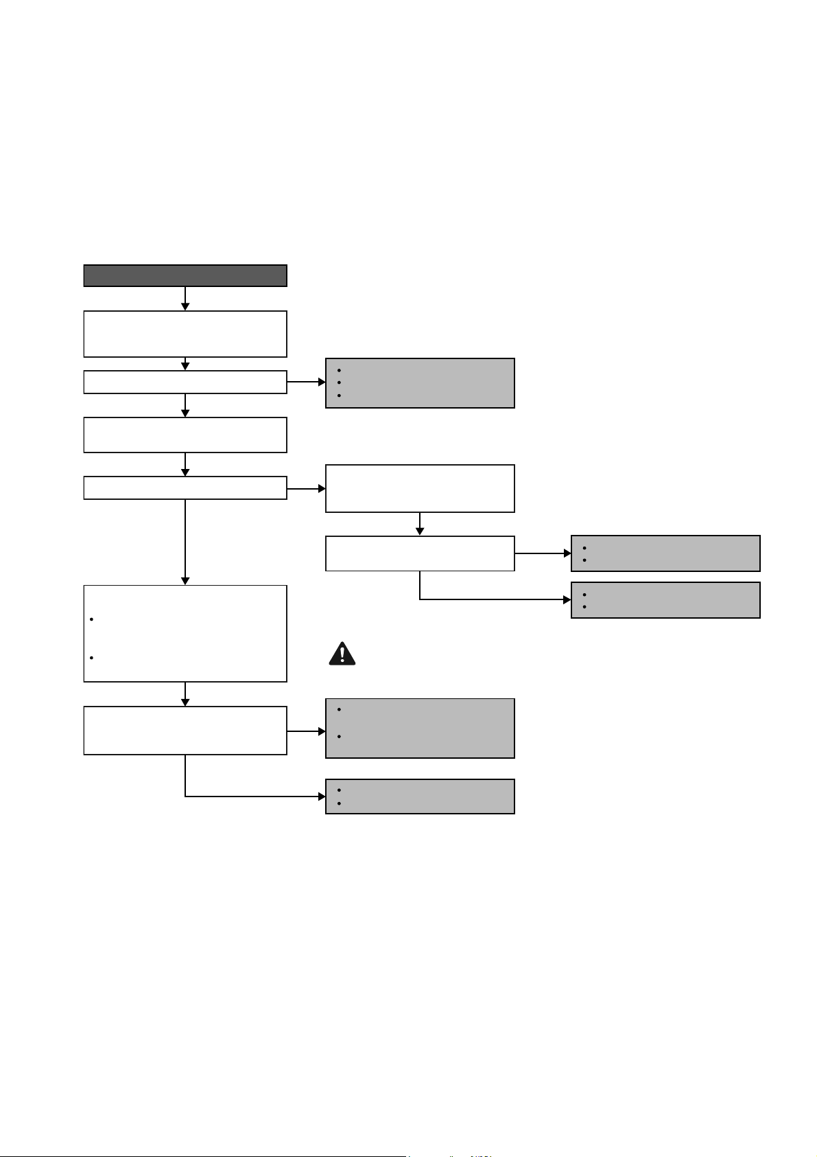
77
15.4.23 F95 (Outdoor High Pressure Protection: Cooling or Soft Dry)
Malfunction Decision Conditions
During operation of cooling or soft dry, when outdoor unit heat exchanger high temperature data is detected by
the outdoor unit heat exchanger thermistor.
Malfunction Caused
Outdoor heat exchanger temperature rise due to short-circuit of hot discharge air flow.
Outdoor heat exchanger temperature rise due to defective of outdoor fan motor.
Outdoor heat exchanger temperature rise due to defective outdoor heat exchanger thermistor.
Outdoor heat exchanger temperature rise due to defective of outdoor unit PCB.
Troubleshooting
When abnormality indication starts again.
Check the outdoor unit installation
condition (during cooling or soft-dry
operation.
Check the outdoor heat exchanger
thermistor:
Turn off the power and disconnect the
connector of outdoor heat exhanger
thermistor from the PCB.
Measure the resistance of the outdoor
heat exchanger thermistor.
Is there any improper heat radiation?
Is the outdoor fan motor operating?
Is the measured resistance of the outdoor
heat exchanger thermistor matches the
value specified in its characteristic chart?
Reset the error code and turn on the unit
again.
Reinstall the outdoor unit.
Remove the obstacle(s).
Clean the outdoor heat exchanger.
Defect in outdoor unit PCB.
Replace the outdoor unit PCB.
Defect in outdoor heat
exchanger thermistor.
Replace the outdoor heat
exchanger thermistor.
Defect in outdoor unit PCB.
Replace the outdoor unit PCB.
Defect in outdoor fan motor.
Replace the outdoor fan motor.
Measure the AC/DC voltage between
pins of connector CN-FM outdoor unit
PCB.
Is the voltage supplied to the outdoor
fan motor normal?
For safety reason and to prevent component
breakdown, always switch off the power before
remove and connect the component.
YES
YES
YES
NO
NO (0V)
YES (240VAC / 265~325VDC)
NO
NO
Caution
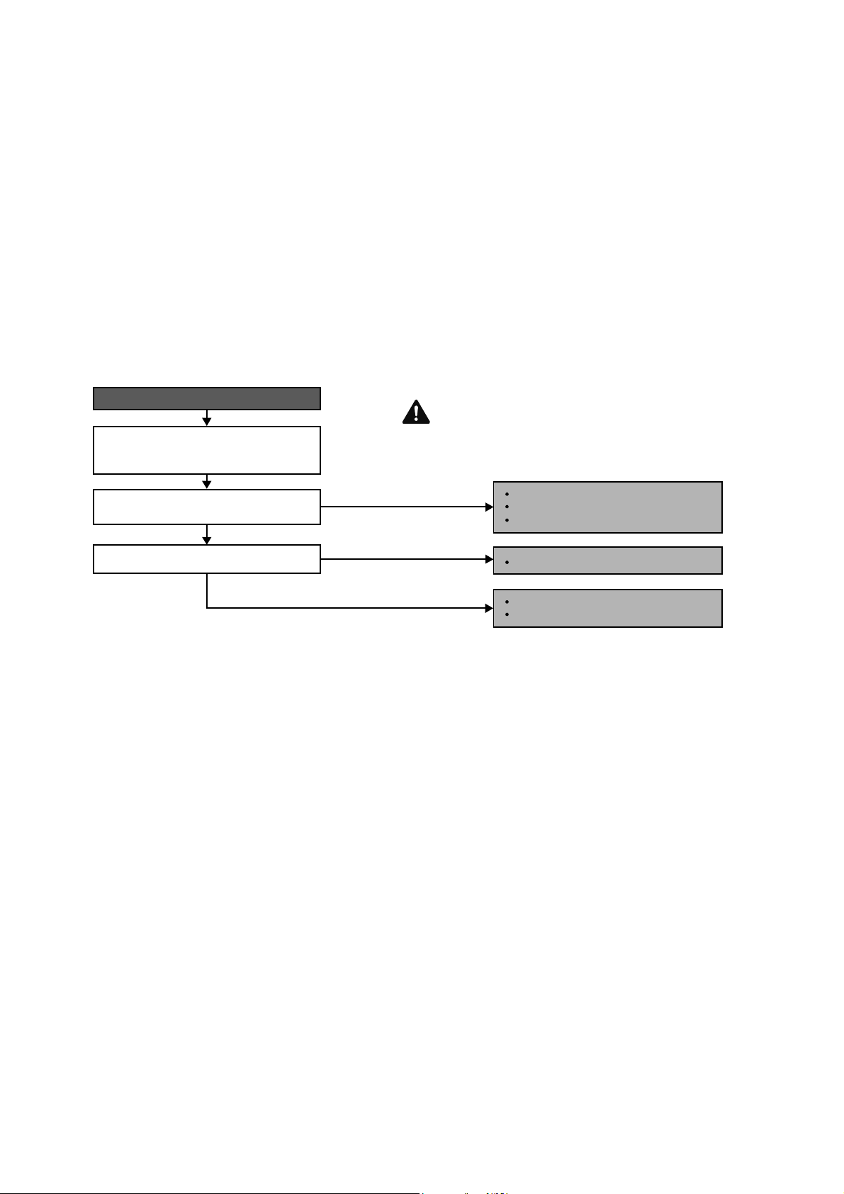
78
15.4.24 F96 (IPM Overheating)
Malfunction Decision Conditions
During operating of cooling and heating, when IPM temperature data 212°F (100°C) is detected by the IPM
temperature sensor.
Multi Models only
o Compressor Overheating: During operation of cooling and heating, when the compressor OL is activated.
o Heat Sink Overheating: During operation of cooling and heating, when heat sink temperature data 194°F
(90°C) is detected by the heat sink temperature sensor.
Malfunction Caused
IPM overheats due to short circuit of hot discharge air flow.
IPM overheats due to defective of outdoor fan motor.
IPM overheats due to defective of internal circuitry of IPM.
IPM overheats due to defective IPM temperature sensor.
Multi Models Only
o Compressor OL connector poor contact.
o Compressor OL faulty.
Troubleshooting
When F96 indication happens For safety reason and to prevent component
breakdown, always switch off the power
before remove and connect the component.
Check the outdoor unit installation
condition (during cooling or soft-dry
operation.
Is there any improper heat radiation?
YES
YES
NO
NO
Reinstall the outdoor unit.
Replace the outdoor fan motor.
Remove the obstacle(s).
Clean the outdoor heat exchanger.
Defect in IPM.
Replace the outdoor unit PCB.
Is outdoor fan motor operating?
Caution
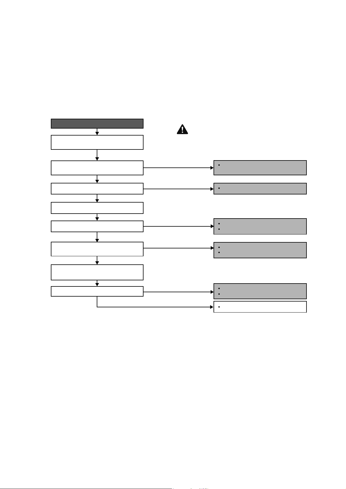
79
15.4.25 F97 (Compressor Overheating)
Malfunction Decision Conditions
During operation of cooling and heating, when compressor tank temperature data 233.6°F (112°C) is detected by
the compressor tank temperature sensor.
Malfunction Caused
Faulty compressor tank temperature sensor
2/3 way valve closed
Refrigerant shortage (refrigerant leakage)
Faulty outdoor unit PCB
Faulty compressor
Troubleshooting
When F97 indication happens.
For safety reason and to prevent component
breakdown, always switch off the power
before remove and connect the component.
Replace the compressor tank.
temperature sensor.
Repair the pipe flare or union nuts.
Reclaim and recharge refrigerant.
Open the 2/3 way valve.
Replace expansion valve and/or strainer.
Reclaim and recharge refrigerant.
Procedure complete.
Check the compressor tank temperature
sensor.
Does it conform to the sensor characteristic
chart?
2/3 way valve closed?
Check for gas leakage.
Oil oozing out from the 2/3 way valve?
Check if expansion valve or strainer
clogged (ice formed).
Reclaim and recharge for a specified
amount of fresh refrigerant.
Refrigerant cycle abnormality error again?
YES
YES
YES
YES
YES
NO
NO
NO
NO
NO
Replace outdoor unit PCB.
Replace outdoor unit compressor.
Caution
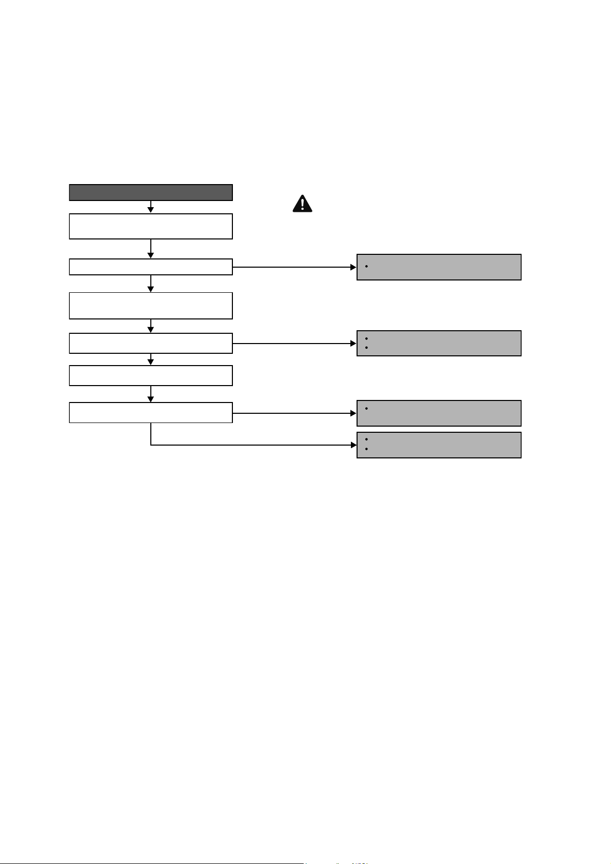
80
15.4.26 F98 (Input Over Current Detection)
Malfunction Decision Conditions
During operation of cooling and heating, when an input over-current (X value in Total Running Current Control) is
detected by checking the input current value being detected by current transformer (CT) with the compressor
running.
Malfunction Caused
Excessive refrigerant.
Faulty outdoor unit PCB.
Troubleshooting
For safety reason and to prevent component
breakdown, always switch off the power
before remove and connect the component.
Replace the outdoor unit PCB.
Repair the pipe flare or union nuts.
Reclaim and recharge refrigerant.
Reclaim and recharge with correct
amount of refrigerant.
Replace outdoor unit PCB.
Replace outdoor unit compressor.
When F98 indication happens.
Get restarted and measure the input
current.
Turn off power supply. Check the main
circuit electrolytic capacitor.
Input current > limit?
Normal?
Check refrigerant amount.
Excess refrigerant?
YES
YES
YES
NO
NO
NO
NO
Caution

81
15.4.27 F99 (DC Peak Detection)
Malfunction Decision Conditions
During startup and operation of cooling and heating, when inverter DC peak data is received by the outdoor internal
DC Peak sensing circuitry.
Malfunction Caused
DC current peak due to compressor failure.
DC current peak due to defective power transistor(s).
DC current peak due to defective outdoor unit PCB.
DC current peak due to short circuit.
Troubleshooting
For safety reason and to prevent component
breakdown, always switch off the power
before remove and connect the component.
Outdoor electronic circuit defect due to
power transistor short.
Excessive amount of refrigerant.
Replace the outdoor unit PCB.
Compressor defective due to
mechanical locked.
Replace compressor.
Compressor defective due to winding
shorted.
Replace compressor.
Amplification IC defect.
Diode defect.
Defect in microcontroller.
Replace the outdoor unit PCB.
When abonormality indication starts again.
Reset the error code and turn on the unit
again.
Istherenochangeevenifallrefrigerant
is discharged?
Are the compressor’s winding resistance
(U-V, V-W or U-W) shorted?
Is there a sound when compressor starts?
Is compressor vibration even?
YES
YES
YES
Turn off the power and disconnect
the harnesses U, V and W.
Measure the winding resistance
between U-V, V-W and W-U.
Check the compressor winding resistance:
NO (Compressor stops)
NO (Normal)
NO (Normal)
NO (Quite a lot of vibration at
start operation)
YES (Stops after 2, 3 seconds
of noise during operation)
Caution
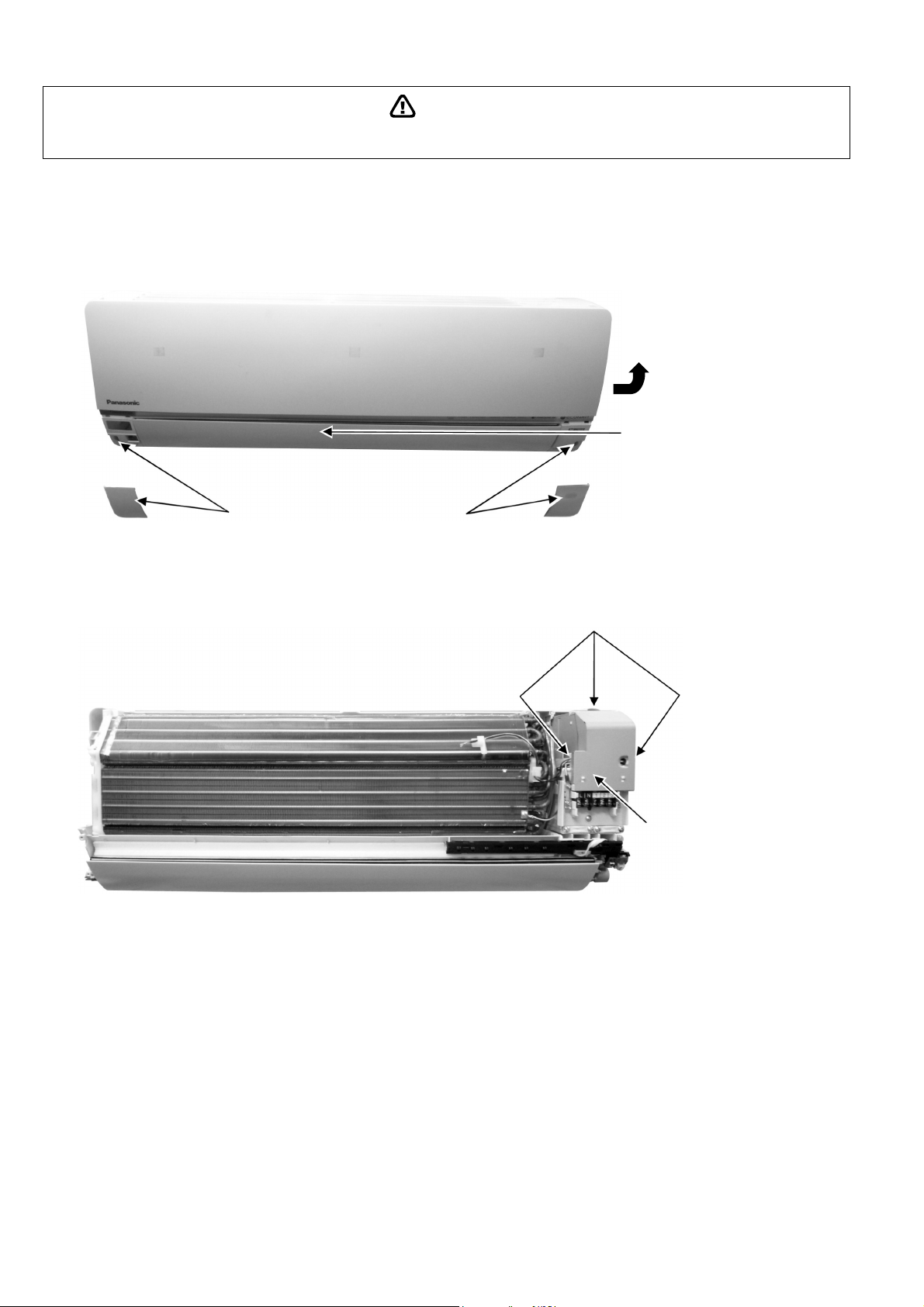
82
WARNING
16. Disassembly and Assembly Instructions
High Voltage is generated in the electrical parts area by the capacitor. Ensure that the capacitor has discharged sufficiently before proceeding with
repair work. Failure to heed this caution may result in electric shocks.
16.1 Indoor Electronic Controllers, Cross Flow Fan and Indoor Fan Motor
Removal Procedures
16.1.1 To remove front grille
Figure 1
16.1.2 To remove electronic controller
Figure 2
1. Remove 2 covers and 2 screws at the bottom
of front grille.
2. Lift to open the horizontal vane
gently.
3. Hold both sides of the front grille and
remove it by pulling up and toward
yourself gently.
3 Hooks (Top, left & right hand side)
4. Remove the control board cover
by releasing the 3 hooks.
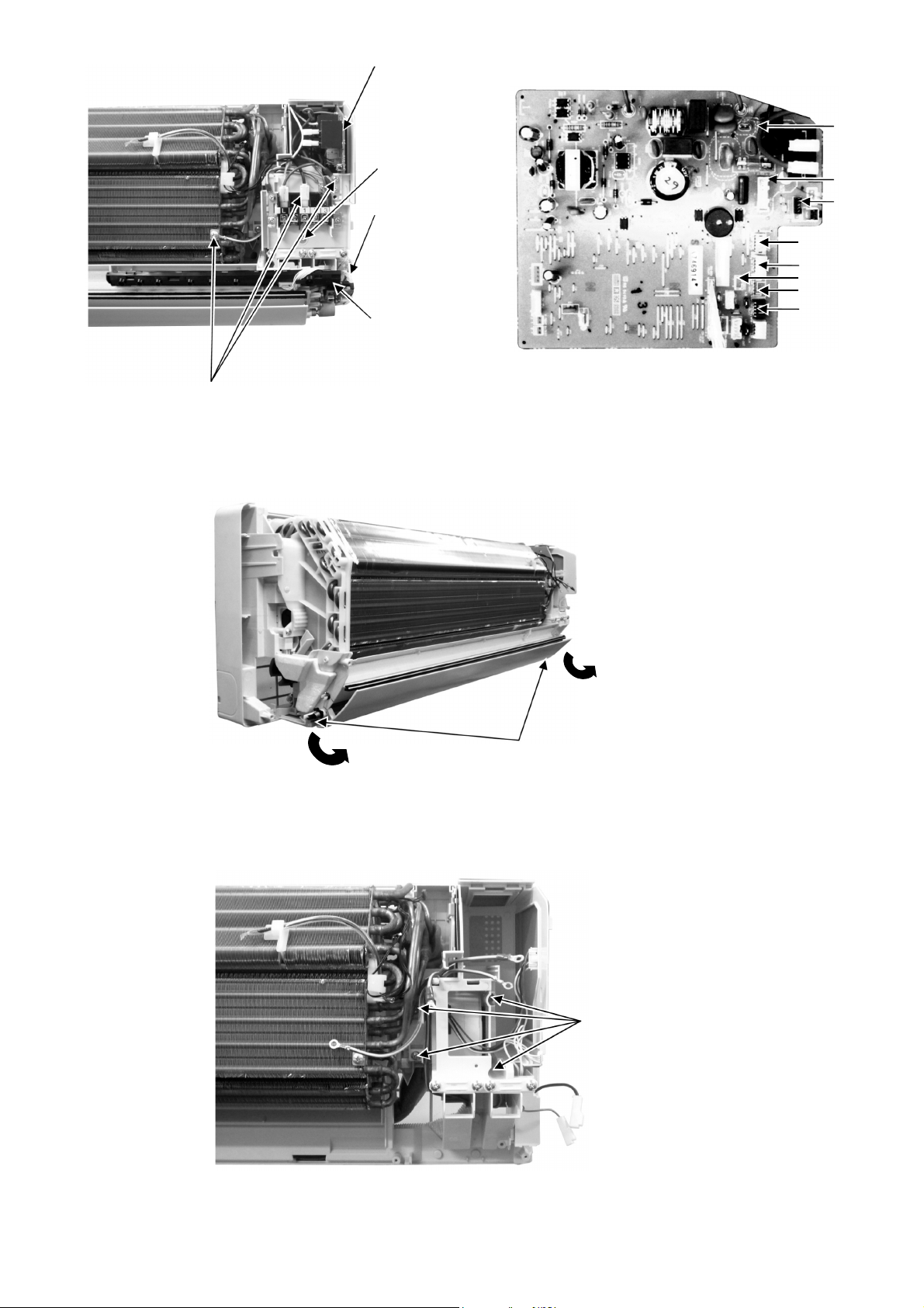
83
Figure 3 Figure 4
16.1.3 To remove discharge grille
Figure 5
16.1.4 To remove control board
Figure 6
CN-MSENS
CN-STM3
CN-STM4
CN-STM2
CN-TH
CN-FM
AC303
CN-STM1
10. Detach 8 connectors as labeled from the electronic controller.
Then pull out electronic controller gently.
9. Pull out the
electronic
controller halfway.
8. Remove screw to
remove terminal
board complete.
7. Detach the
connectors
CN2 (Black),
GND (Green),
and CN1 (White)
then remove the
high voltage
generator.
6. Remove the
indicator complete
then detach the
connectors CN-DISP
and CN-RCV.
5. Detach the earth wire screw, terminal wire (Brown), terminal wire (Black),
terminal wire (Red) and earth wire screw (Green).
12. Pull out to remove the drain
hose from the discharge grille.
11. Detach the bottom plate then remove
2 screws of the discharge grille.
13. Then pull the discharge grille downward gently to dismantle it.
14. Remove the 4 screws holding
the control board then pull ou
t
the control board.
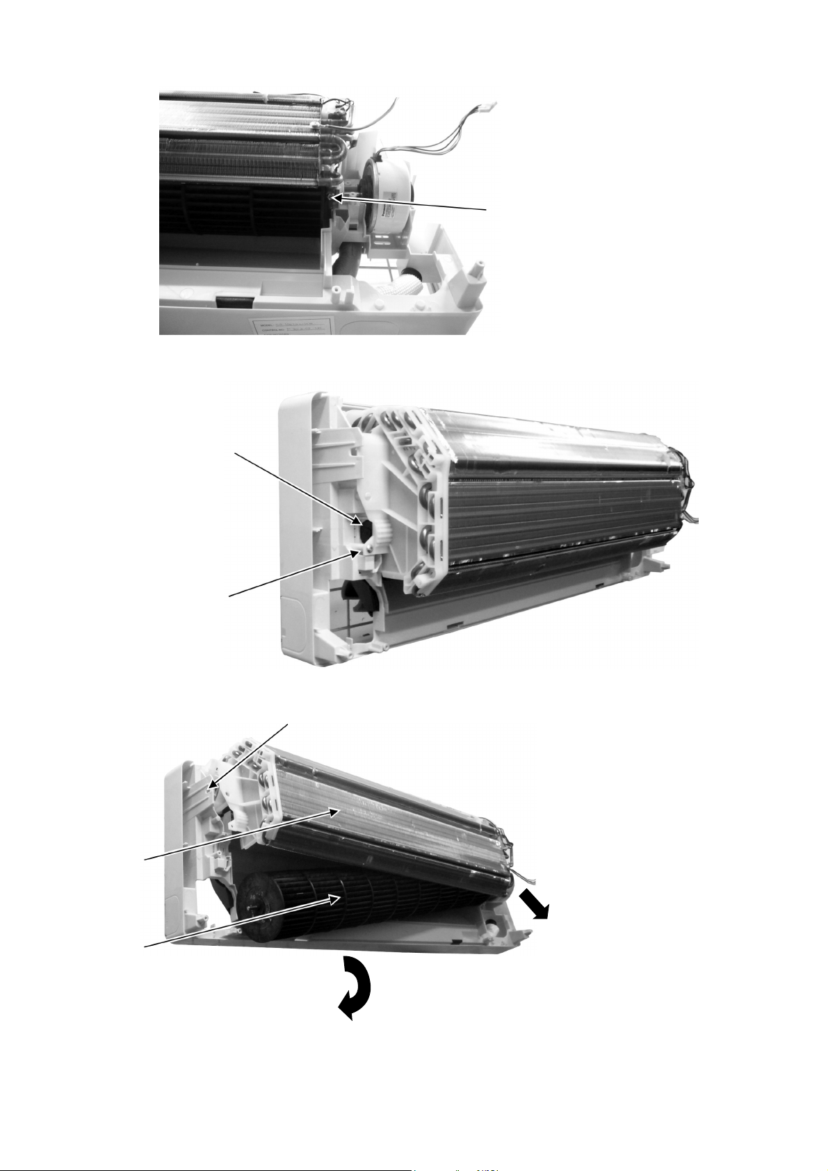
84
16.1.5 To remove cross flow fan and indoor fan motor
Figure 7
Figure 8
Figure 9
15. Remove the screw that holding
the cross flow fan and fan motor
axis.
16. Remove the screw from the
evaporator.
17. Remove the bearing by pulling it
out gently.
18. Push the holdfast to the left and lift up the evaporator.
20. Fan motor can be removed after the
removal of the cross flow fan.
19. Remove the cross flow fan from the unit by
pulling it to the left and downward.
Cross flow fan
Evaporator
Reminder: To reinstall the fan motor, adjust
the fan motor connector to 90° towards you
before fixing control board.
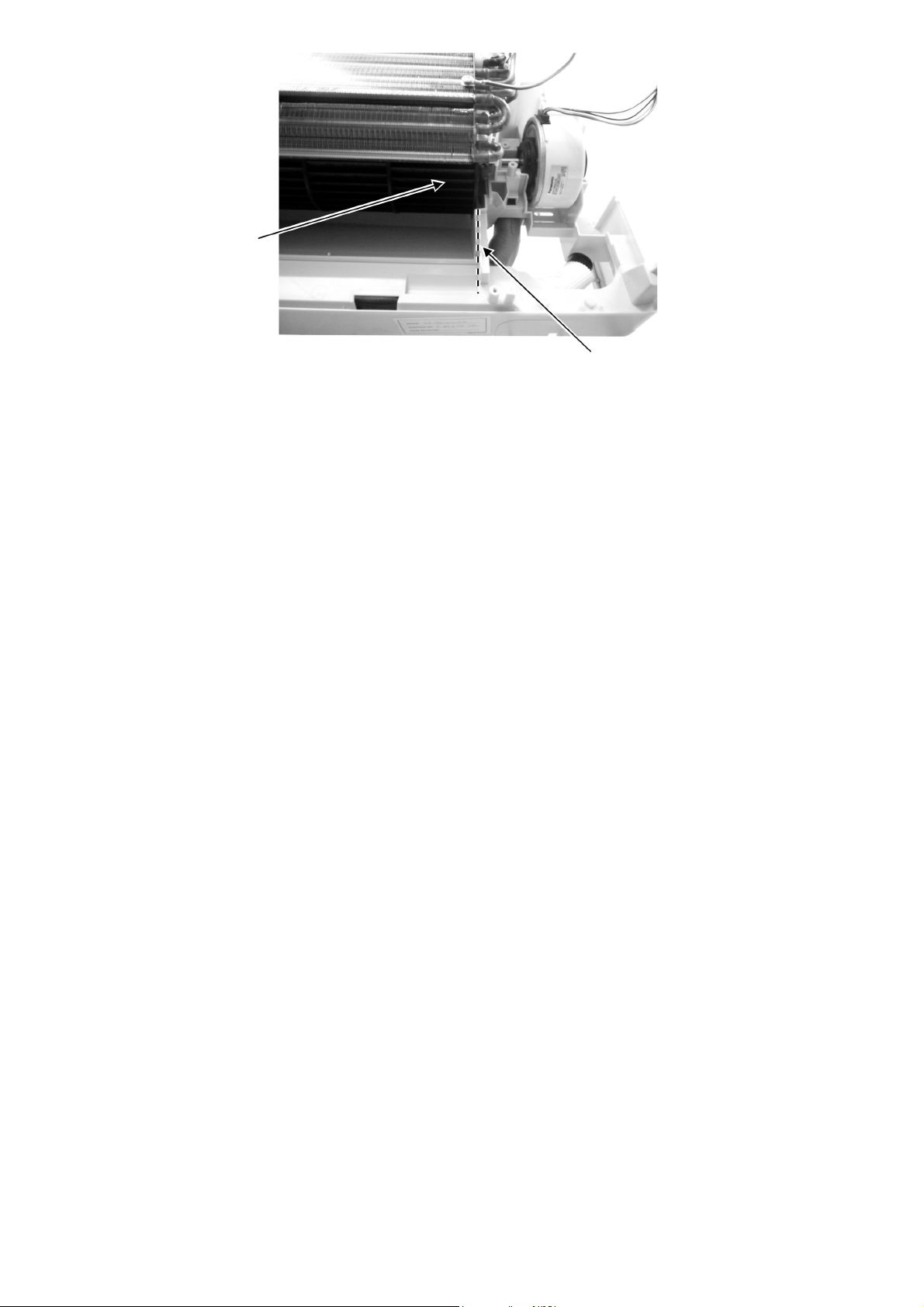
85
Figure 10
Reminder: To reinstall the cross flow
fan, ensure cross flow fan is in line as
showninfigure10.
Cross Flow Fan
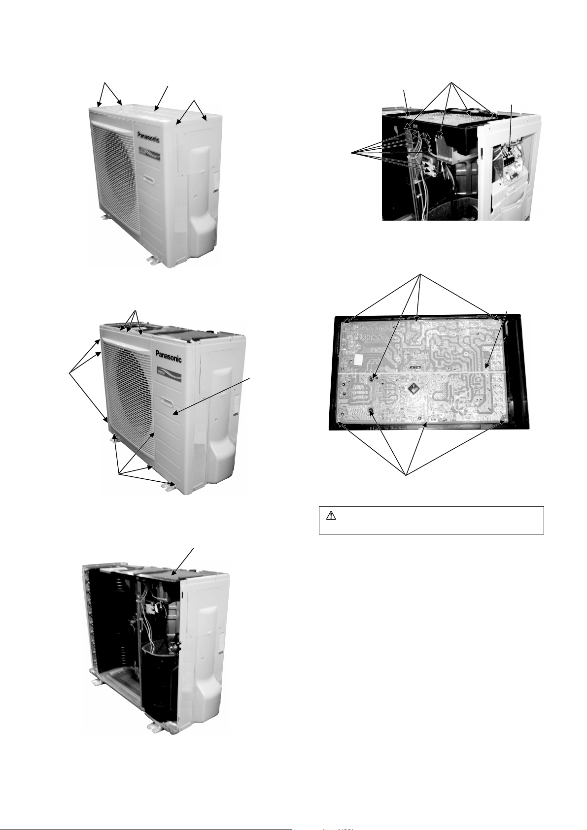
86
16.2 Outdoor Electronic Controller Removal Procedure
1 Remove the 4 screws of the Top Panel.
Fig.1
2 Remove the 10 screws of the Front Panel.
Fig.2
3 Remove the Top Cover of the Electronic
Controller.
Fig.3
4 Remove the Control Board.
Fig.4
5 Remove the 8 screws of the Electronic
Controller.
Fig.5
Caution! When handling electronic controller, be careful of
electrostatic discharge.
S
c
r
e
ws
Screws
Top Panel
Sc
r
e
ws
Screws
Screws
Front
Panel
T
o
p
C
ov
e
r
Release
6 terminal
connectors
Control Board
R
elease 6
c
onnectors
R
e
l
e
a
s
e
th
e
H
o
o
k
s
S
c
r
e
w
s
S
c
r
e
w
s
Electronic
Controller
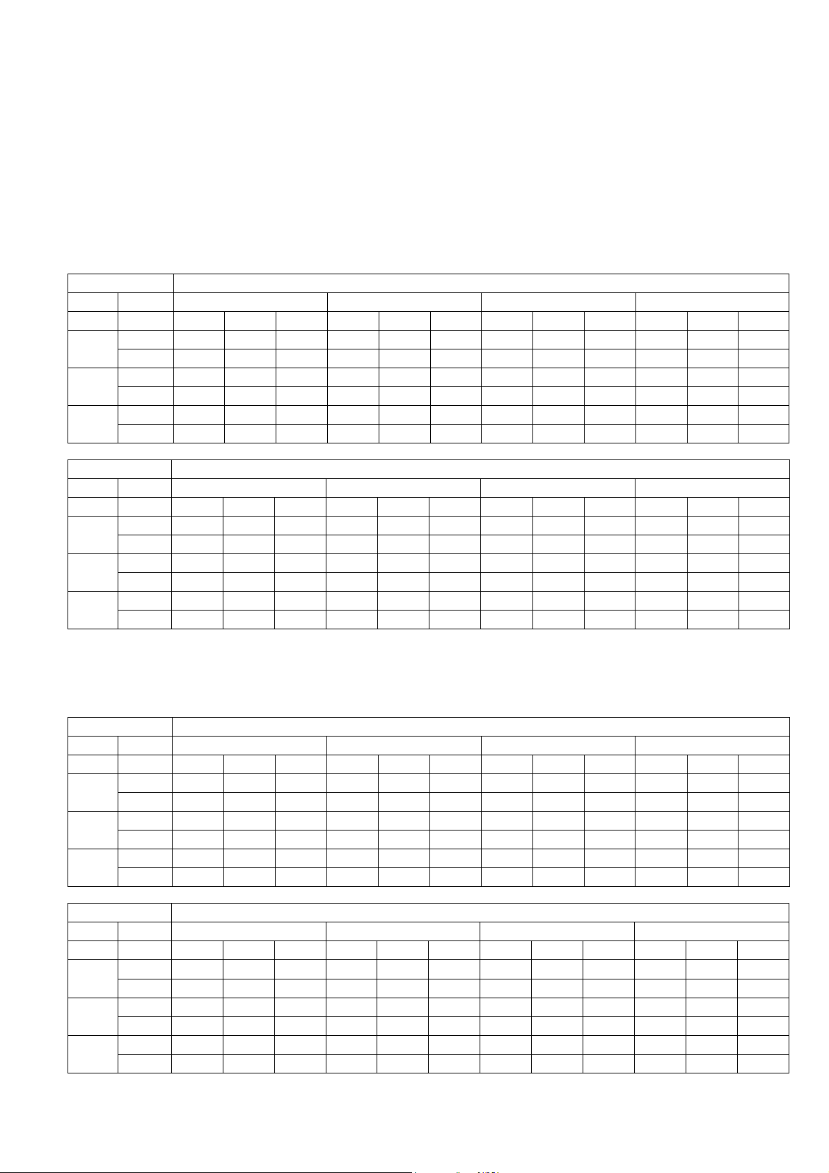
87
17. Technical Data
Technical data provided are based on the air conditioner running under free frequency.
17.1 Cool Mode Performance Data
Unit setting: Standard piping length, Hi Fan, Cool mode at 16°C (60.8°F)
Voltage: 208V/230V
17.1.1 CS-XE9SKUA CU-XE9SKUA
Rated frequency (compressor speed is fixed during forced heating or cooling for capacity measurement and
diagnosis purpose)
Indoor (°C / °F) Outdoor (°C / °F)
DB WB -20 (-4.0) -10 (14.0) 0 (32.0) 5 (41.0)
TC SHC IP TC SHC IP TC SHC IP TC SHC IP
27
(80.6)
19 (66.2) 2865 2592 376 2865 2592 382 2851 2615 372 2910 2669 352
22 (71.6) 3027 1842 399 3027 1842 406 3046 1869 382 3288 1986 285
23
(73.4)
16 (60.8) 2681 2654 359 2681 2654 364 2591 2565 390 2935 2906 313
18 (64.4) 2820 1835 368 2820 1835 374 2731 1804 391 2885 1898 330
20
(68.0)
13 (55.4) 2547 2522 388 2547 2522 394 2457 2432 404 2252 2229 277
16 (60.8) 2625 1825 396 2625 1825 402 2632 1812 388 2370 1709 263
Indoor (°C / °F) Outdoor (°C / °F)
DB WB 16 (60.8) 25 (77.0) 35 (95.0) 46 (114.8)
TC SHC IP TC SHC IP TC SHC IP TC SHC IP
27
(80.6)
19 (66.2) 3028 2602 312 2675 2397 456 2550 2423 510 2092 1875 612
22 (71.6) 3127 1859 311 2920 1683 436 2715 1682 501 2284 1316 586
23
(73.4)
16 (60.8) 2686 2659 350 2423 2399 468 2350 2326 517 1895 1876 628
18 (64.4) 2841 1841 337 2663 1697 455 2410 1736 510 2083 1327 611
20
(68.0)
13 (55.4) 1990 1970 155 1973 1953 353 2159 2138 519 1465 1450 475
16 (60.8) 2282 1622 297 2372 1660 466 2195 1666 514 1855 1299 626
17.1.2 CS-XE12SKUA CU-XE12SKUA
Rated frequency (compressor speed is fixed during forced heating or cooling for capacity measurement and
diagnosis purpose)
Indoor (°C / °F) Outdoor (°C / °F)
DB WB -20 (-4.0) -10 (14.0) 0 (32.0) 5 (41.0)
TC SHC IP TC SHC IP TC SHC IP TC SHC IP
27
(80.6)
19 (66.2) 3775 3415 575 3775 3415 584 3757 3445 569 3835 3517 538
22 (71.6) 3989 2428 611 3989 2428 621 4013 2463 584 4333 2617 436
23
(73.4)
16 (60.8) 3533 3497 549 3533 3497 557 3414 3380 596 3867 3829 479
18 (64.4) 3716 2418 563 3716 2418 572 3599 2377 599 3802 2501 505
20
(68.0)
13 (55.4) 3357 3323 594 3357 3323 603 3237 3205 618 2967 2937 424
16 (60.8) 3459 2405 605 3459 2405 615 3468 2387 593 3123 2252 402
Indoor (°C / °F) Outdoor (°C / °F)
DB WB 16 (60.8) 25 (77.0) 35 (95.0) 46 (114.8)
TC SHC IP TC SHC IP TC SHC IP TC SHC IP
27
(80.6)
19 (66.2) 3990 3428 478 3525 3158 698 3360 3192 780 2757 2470 937
22 (71.6) 4121 2450 475 3847 2218 667 3577 2216 766 3009 1735 896
23
(73.4)
16 (60.8) 3539 3503 535 3193 3161 715 3096 3065 790 2497 2472 961
18 (64.4) 3743 2426 516 3508 2236 696 3176 2288 780 2744 1749 935
20
(68.0)
13 (55.4) 2623 2596 236 2599 2573 541 2845 2817 793 1930 1910 726
16 (60.8) 3007 2137 455 3125 2188 713 2892 2196 785 2444 1711 957
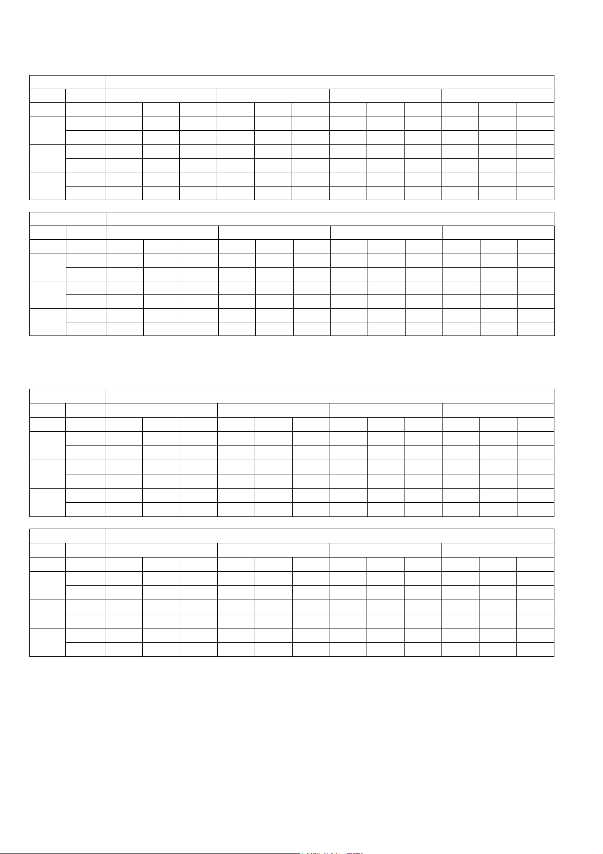
88
17.1.3 CS-XE9SKUA CU-XE9SKUA
Maximum Capacity
Indoor (°C / °F) Outdoor (°C / °F)
DB WB -20 (-4.0) -10 (14.0) 0 (32.0) 5 (41.0)
TC SHC IP TC SHC IP TC SHC IP TC SHC IP
27
(80.6)
19 (66.2) 2865 2592 376 2865 2592 382 2851 2615 372 2910 2669 352
22 (71.6) 3027 1842 399 3027 1842 406 3046 1869 382 3288 1986 285
23
(73.4)
16 (60.8) 2681 2654 359 2681 2654 364 2591 2565 390 2935 2906 313
18 (64.4) 2820 1835 368 2820 1835 374 2731 1804 391 2885 1898 330
20
(68.0)
13 (55.4) 2547 2522 388 2547 2522 394 2457 2432 404 2252 2229 277
16 (60.8) 2625 1825 396 2625 1825 402 2632 1812 388 2370 1709 263
Indoor (°C / °F) Outdoor (°C / °F)
DB WB 16 (60.8) 25 (77.0) 35 (95.0) 46 (114.8)
TC SHC IP TC SHC IP TC SHC IP TC SHC IP
27
(80.6)
19 (66.2) 3286 3166 432 3582 3299 730 3510 3335 850 2880 2580 878
22 (71.6) 3578 2365 500 3775 2234 670 3737 2315 835 3143 1812 839
23
(73.4)
16 (60.8) 3233 3498 530 3271 3337 751 3235 3202 861 2609 2583 901
18 (64.4) 3141 1841 337 3416 2177 671 3318 2390 850 2867 1827 876
20
(68.0)
13 (55.4) 2349 2622 274 2463 2636 564 2900 2943 864 2016 1996 680
16 (60.8) 2706 2136 482 2854 2138 691 2951 2294 856 2553 1788 897
17.1.4 CS-XE12SKUA CU-XE12SKUA
Maximum Capacity
Indoor (°C / °F) Outdoor (°C / °F)
DB WB -20 (-4.0) -10 (14.0) 0 (32.0) 5 (41.0)
TC SHC IP TC SHC IP TC SHC IP TC SHC IP
27
(80.6)
19 (66.2) 3775 3415 575 3775 3415 584 3757 3445 569 3835 3517 538
22 (71.6) 3989 2428 611 3989 2428 621 4013 2463 584 4333 2617 436
23
(73.4)
16 (60.8) 3533 3497 549 3533 3497 557 3414 3380 596 3867 3829 479
18 (64.4) 3716 2418 563 3716 2418 572 3599 2377 599 3802 2501 505
20
(68.0)
13 (55.4) 3357 3323 594 3357 3323 603 3237 3205 618 3067 2937 424
16 (60.8) 3459 2405 605 3459 2405 615 3468 2387 593 3223 2252 402
Indoor (°C / °F) Outdoor (°C / °F)
DB WB 16 (60.8) 25 (77.0) 35 (95.0) 46 (114.8)
TC SHC IP TC SHC IP TC SHC IP TC SHC IP
27
(80.6)
19 (66.2) 3990 3428 478 4101 3853 902 4100 3895 1050 3364 3014 1085
22 (71.6) 4547 2763 618 4526 2609 828 4365 2704 1032 3672 2117 1037
23
(73.4)
16 (60.8) 3987 4086 655 3937 3898 928 3778 3740 1064 3047 3017 1113
18 (64.4) 4014 2666 594 3991 2543 829 3876 2791 1049 3348 2134 1083
20
(68.0)
13 (55.4) 2994 3063 338 3111 3079 697 3472 3437 1068 2355 2331 841
16 (60.8) 3411 2496 595 3567 2497 854 3528 2679 1057 2982 2088 1108
TC - Total Cooling Capacity (W)
SHC - Sensible Heat Capacity (W)
IP - Input Power (W)
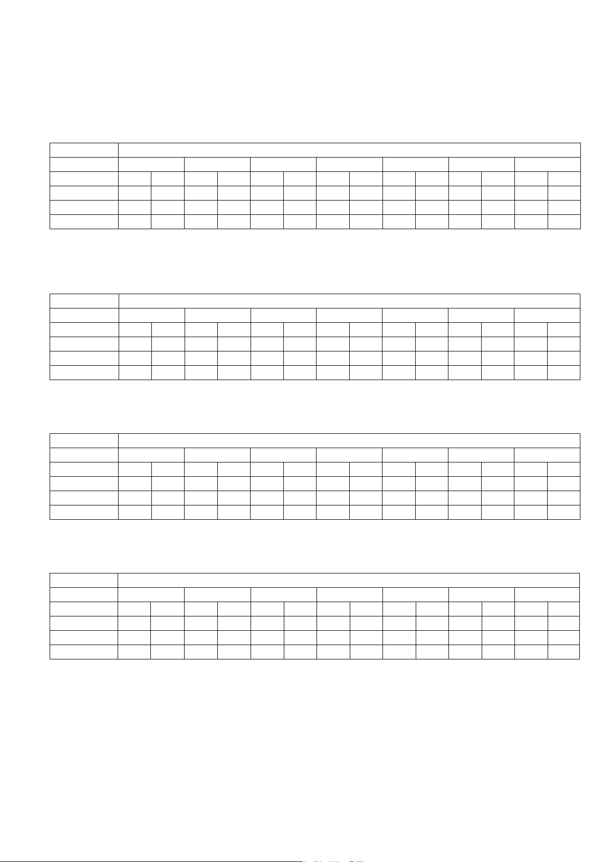
89
17.2 Heat Mode Performance Data
Unit setting: Standard piping length, Hi Fan, Heat mode at 30°C (86°F)
Voltage: 208V/230V
17.2.1 CS-XE9SKUA CU-XE9SKUA
Rated frequency (compressor speed is fixed during forced heating or cooling for capacity measurement and
diagnosis purpose)
Indoor (°C / °F) Outdoor (°C / °F)
DB -26 (-14.8) -20 (-4.0) -8.3 (17.06) 1.7 (35.06) 8.3 (46.94) 12 (53.6) 23.9 (75.02)
TC IP TC IP TC IP TC IP TC IP TC IP TC IP
24 (75.2) 266 247 1166 447 2020 621 2611 675 3223 675 3307 687 3921 666
20 (68.0) 329 241 1229 441 2100 619 2686 662 3210 670 3275 672 4183 652
16 (60.8) 121 230 992 430 2212 613 2921 667 3445 688 3471 661 4043 641
17.2.2 CS-XE12SKUA CU-XE12SKUA
Rated frequency (compressor speed is fixed during forced heating or cooling for capacity measurement and
diagnosis purpose)
Indoor (°C / °F) Outdoor (°C / °F)
DB -26 (-14.8) -20 (-4.0) -8.3 (17.06) 1.7 (35.06) 8.3 (46.94) 12 (53.6) 23.9 (75.02)
TC IP TC IP TC IP TC IP TC IP TC IP TC IP
24 (75.2) 400 433 1550 633 2421 881 3100 957 4006 958 4111 974 4565 945
20 (68.0) 527 425 1627 625 2560 878 3185 939 3990 950 4070 953 4826 924
16 (60.8) 233 409 1333 609 2712 869 3412 946 4282 975 4315 937 4705 908
17.2.3 CS-XE9SKUA CU-XE9SKUA
Maximum Capacity
Indoor (°C / °F) Outdoor (°C / °F)
DB -26 (-14.8) -20 (-4.0) -8.3 (17.06) 1.7 (35.06) 8.3 (46.94) 12 (53.6) 23.9 (75.02)
TC IP TC IP TC IP TC IP TC IP TC IP TC IP
24 (75.2) 1042 1131 2142 1431 3100 1452 4091 1604 5311 1663 5443 1677 5900 1566
20 (68.0) 1043 1125 2143 1425 3300 1446 4198 1574 5290 1650 5425 1640 6304 1532
16 (60.8) 747 1087 1747 1387 3455 1432 4597 1587 5677 1693 5712 1612 6079 1506
17.2.4 CS-XE12SKUA CU-XE12SKUA
Maximum Capacity
Indoor (°C / °F) Outdoor (°C / °F)
DB -26 (-14.8) -20 (-4.0) -8.3 (17.06) 1.7 (35.06) 8.3 (46.94) 12 (53.6) 23.9 (75.02)
TC IP TC IP TC IP TC IP TC IP TC IP TC IP
24 (75.2) 1657 1421 2757 1821 4100 1848 5220 2042 6747 2117 6914 2134 7600 1994
20 (68.0) 1612 1413 2712 1813 4316 1841 5333 2003 6720 2100 6845 2088 8008 1950
16 (60.8) 1154 1355 2254 1765 4552 1822 5810 2020 7212 2155 7256 2052 7798 1917
TC - Total Heating Capacity (W)
IP - Input Power (W)
90
18. Service Data
Service data provided are based on the air conditioner running under rated frequency during forced cooling / forced
heating mode.
18.1 Cool Mode Outdoor Air Temperature Characteristic
Condition
Indoor room temperature: 26.7°C (80°F) Dry Bulb/19.4°C (67°F) Wet Bulb
Unit setting: Standard piping length, forced cooling at 16°C (60.8°F), Hi fan
Compressor frequency: Rated for cooling operation
Piping Length: 7.5 m (24.6 ft)
Voltage: 208V/230V
18.1.1 CS-XE9SKUA CU-XE9SKUA
-4
(-20.0)
6
(-14.4)
16
(-8.8)
26
(-3.3)
36
(2.2)
46
(7.7)
56
(13.3)
66
(18.8)
76
(24.4)
86
(30.0)
96
(35.5)
106
(41.1)
116
(46.6)
Current
(A)
Gas Side Piping
Pressure (PSI (MPa))
Outlet Air
(°F (°C))
61.0 (16.1)
62.0 (16.6)
63.0 (17.2)
64.0 (17.7)
65.0 (18.3)
66.0 (18.8)
67.0 (19.4)
68.0 (20.0)
Outdoor Air Temperature (°F (°C))
-4
(-20.0)
6
(-14.4)
16
(-8.8)
26
(-3.3)
36
(2.2)
46
(7.7)
56
(13.3)
66
(18.8)
76
(24.4)
86
(30.0)
96
(35.5)
106
(41.1)
116
(46.6)
Outdoor Air Temperature (°F (°C))
-4
(-20.0)
6
(-14.4)
16
(-8.8)
26
(-3.3)
36
(2.2)
46
(7.7)
56
(13.3)
66
(18.8)
76
(24.4)
86
(30.0)
96
(35.5)
106
(41.1)
116
(46.6)
Outdoor Air Temperature (°F (°C))
208
230
1.600
1.800
2.000
2.200
2.400
2.600
2.800
3.000
3.200
120.000 (0.827)
125.000 (0.861)
130.000 (0.896)
135.000 (0.930)
140.000 (0.965)
145.000 (0.999)
150.000 (1.034)
155.000 (1.068)
160.000 (1.103)
165.000 (1.137)
170.000 (1.172)
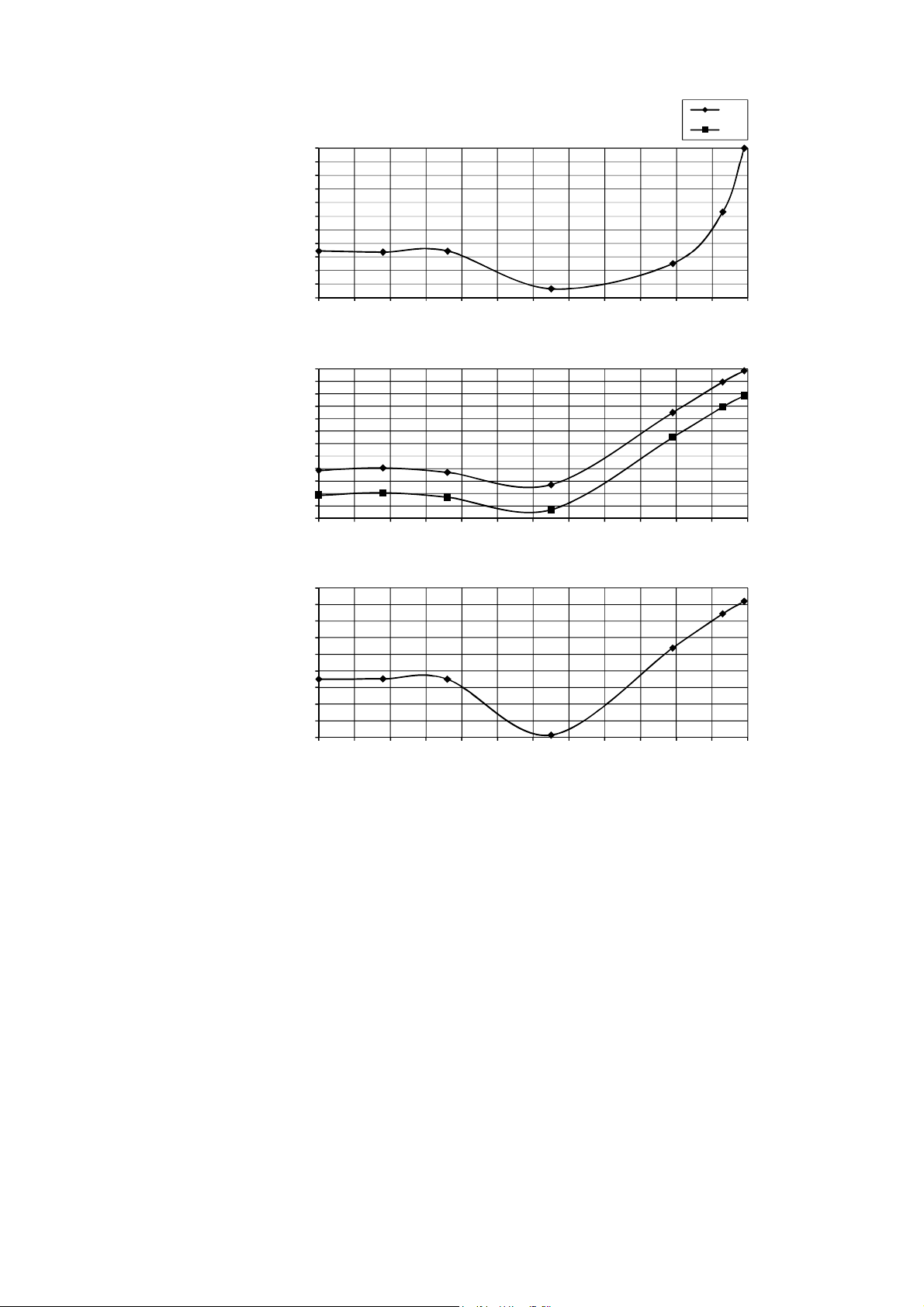
91
18.1.2 CS-XE12SKUA CU-XE12SKUA
-4
(-20.0)
6
(-14.4)
16
(-8.8)
26
(-3.3)
36
(2.2)
46
(7.7)
56
(13.3)
66
(18.8)
76
(24.4)
86
(30.0)
96
(35.5)
106
(41.1)
116
(46.6)
Current
(A)
Gas Side Piping
Pressure (PSI (MPa))
Outlet Air
(°F (°C))
Outdoor Air Temperature (°F (°C))
208
230
59.0 (15.0)
59.5 (15.2)
60.0 (15.5)
60.5 (15.8)
61.0 (16.1)
61.5 (16.3)
62.0 (16.6)
62.5 (16.9)
63.0 (17.2)
63.5 (17.5)
64.0 (17.7)
64.5 (18.0)
2.400
2.600
2.800
3.000
3.200
3.400
3.600
3.800
4.000
4.200
4.400
4.600
4.800
125.000 (0.861)
130.000 (0.896)
135.000 (0.930)
140.000 (0.965)
145.000 (0.999)
150.000 (1.034)
155.000 (1.068)
160.000 (1.103)
165.000 (1.137)
170.000 (1.172)
-4
(-20.0)
6
(-14.4)
16
(-8.8)
26
(-3.3)
36
(2.2)
46
(7.7)
56
(13.3)
66
(18.8)
76
(24.4)
86
(30.0)
96
(35.5)
106
(41.1)
116
(46.6)
Outdoor Air Temperature (°F (°C))
-4
(-20.0)
6
(-14.4)
16
(-8.8)
26
(-3.3)
36
(2.2)
46
(7.7)
56
(13.3)
66
(18.8)
76
(24.4)
86
(30.0)
96
(35.5)
106
(41.1)
116
(46.6)
Outdoor Air Temperature (°F (°C))

92
18.2 Heat Mode Outdoor Air Temperature Characteristic
Condition
Indoor room temperature: 20°C (68°F) Dry Bulb/ -°C Wet Bulb
Unit setting: Standard piping length, forced heating at 30°C (86°F), Hi fan
Compressor frequency: Rated for Heating operation
Piping Length: 7.5 m (24.6 ft)
Voltage: 208V/230V
18.2.1 CS-XE9SKUA CU-XE9SKUA
Current
(A)
Gas Side Piping
Pressure (PSI (MPa))
Outlet Air
(°F (°C))
-15
(-26.1)
-5
(-20.5)
5
(-15)
15
(-9.4)
25
(-3.8)
35
(1.6)
45
(7.2)
55
(12.7)
65
(18.3)
75
(23.8)
Outdoor Air Temperature (°F (°C))
208
230
65.0 (18.3)
70.0 (21.1)
75.0 (23.8)
80.0 (26.6)
85.0 (29.4)
90.0 (32.2)
95.0 (35.0)
100.0 (37.7)
105.0 (40.5)
110.0 (43.3)
1.500
2.000
2.500
3.000
3.500
4.000
4.500
150.000 (1.034)
200.000 (1.378)
250.000 (1.723)
300.000 (2.068)
350.000 (2.413)
400.000 (2.757)
450.000 (3.102)
-15
(-26.1)
-5
(-20.5)
5
(-15)
15
(-9.4)
25
(-3.8)
35
(1.6)
45
(7.2)
55
(12.7)
65
(18.3)
75
(23.8)
Outdoor Air Temperature (°F (°C))
-15
(-26.1)
-5
(-20.5)
5
(-15)
15
(-9.4)
25
(-3.8)
35
(1.6)
45
(7.2)
55
(12.7)
65
(18.3)
75
(23.8)
Outdoor Air Temperature (°F (°C))
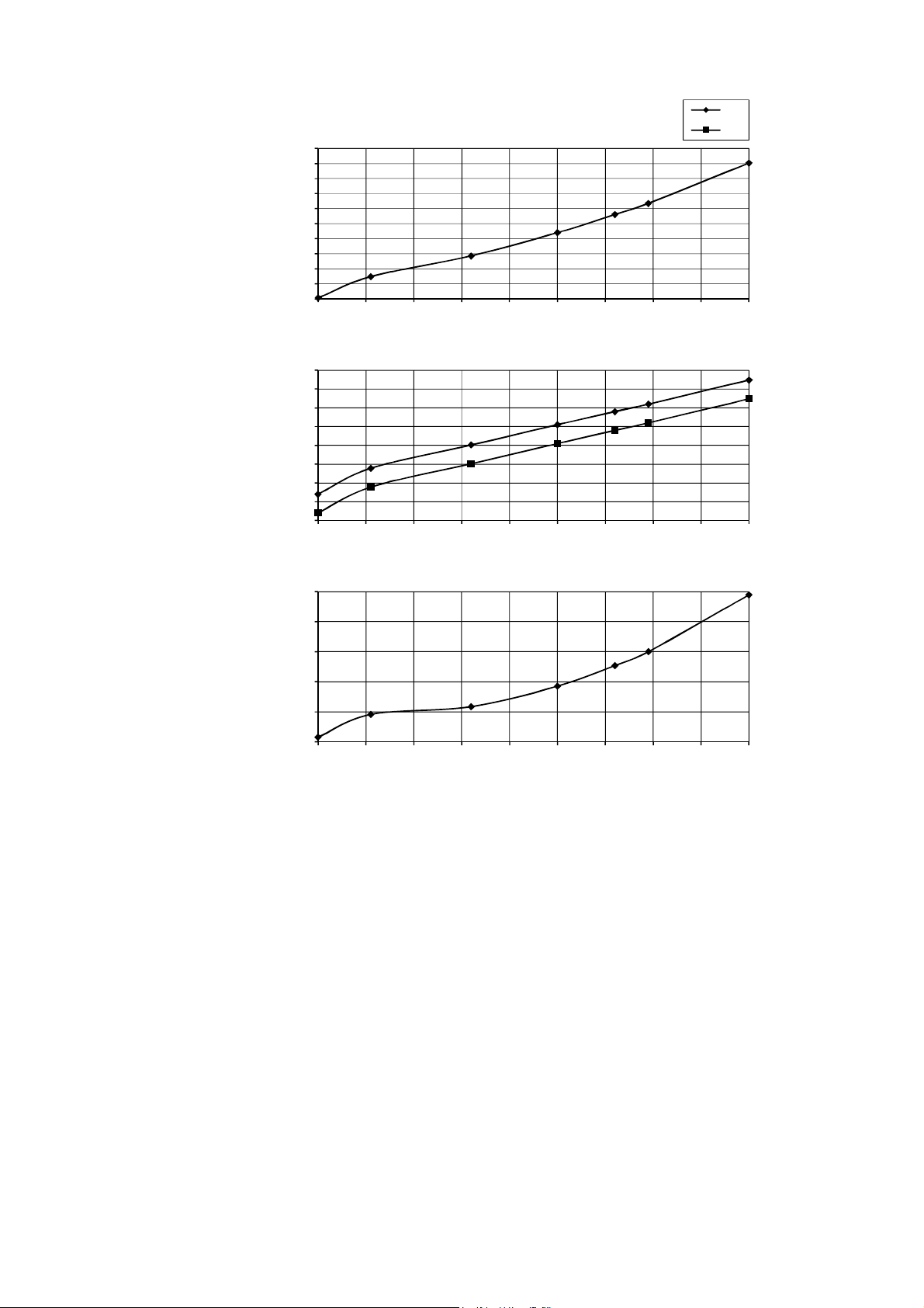
93
18.2.2 CS-XE12SKUA CU-XE12SKUA
Current
(A)
Gas Side Piping
Pressure (PSI (MPa))
Outlet Air
(°F (°C))
-15
(-26.1)
-5
(-20.5)
5
(-15)
15
(-9.4)
25
(-3.8)
35
(1.6)
45
(7.2)
55
(12.7)
65
(18.3)
75
(23.8)
Outdoor Air Temperature (°F (°C))
208
230
70.0 (21.1)
75.0 (23.8)
80.0 (26.6)
85.0 (29.4)
90.0 (32.2)
95.0 (35.0)
100.0 (37.7)
105.0 (40.5)
110.0 (43.3)
115.0 (46.1)
120.0 (48.8)
2.000
2.500
3.000
3.500
4.000
4.500
5.000
5.500
6.000
200.000 (1.378)
250.000 (1.723)
300.000 (2.068)
350.000 (2.413)
400.000 (2.757)
450.000 (3.102)
-15
(-26.1)
-5
(-20.5)
5
(-15)
15
(-9.4)
25
(-3.8)
35
(1.6)
45
(7.2)
55
(12.7)
65
(18.3)
75
(23.8)
Outdoor Air Temperature (°F (°C))
-15
(-26.1)
-5
(-20.5)
5
(-15)
15
(-9.4)
25
(-3.8)
35
(1.6)
45
(7.2)
55
(12.7)
65
(18.3)
75
(23.8)
Outdoor Air Temperature (°F (°C))
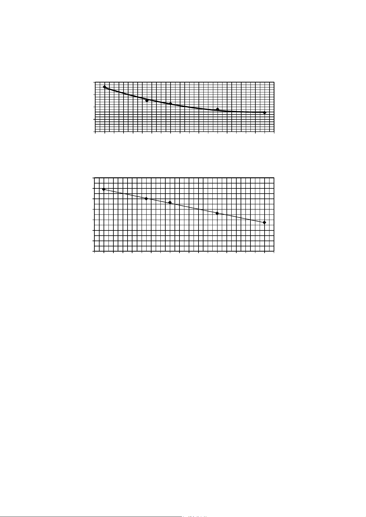
94
18.3 Piping Length Correction Factor
The characteristic of the unit has to be corrected in accordance with the piping length.
18.3.1 CS-XE9SKUA CU-XE9SKUA CS-XE12SKUA CU-XE12SKUA
18.3.1.1 Cooling Capacity
18.3.1.2 Heating Capacity
Note: The graphs show the factor after added right amount of additional refrigerant.
0.95
0.97
0.99
1.01
1.03
2
(6.5)
3
(9.8)
4
(13.1)
5
(16.4)
6
(19.6)
7
(22.9)
8
(26.2)
9
(29.5)
10
(32.8)
11
(36.0)
12
(39.3)
13
(42.6)
14
(45.9)
15
(49.2)
16
(52.4)
17
(55.7)
18
(59.0)
19
(62.3)
20
(65.6)
21
(68.8
)
Piping length m (ft)
Capacity correction factor
0.95
0.96
0.97
0.98
0.99
1.00
1.01
1.02
2
(6.5)
3
(9.8)
4
(13.1)
5
(16.4)
6
(19.6)
7
(22.9)
8
(26.2)
9
(29.5)
10
(32.8)
11
(36.0)
12
(39.3)
13
(42.6)
14
(45.9)
15
(49.2)
16
(52.4)
17
(55.7)
18
(59.0)
19
(62.3)
20
(65.6)
21
(68.8)
Piping length m (ft)
Capacity correction factor
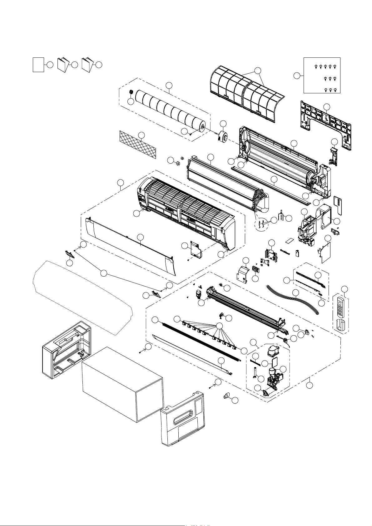
95
19. Exploded View and Replacement Parts List
19.1 Indoor Unit
Note
The above exploded view is for the purpose of parts disassembly and replacement.
The non-numbered parts are not kept as standard service parts.
CWH55025J
XSN4+30FJ
XTN4+14AFJ
O/I
I/I I/I
39
A
B
A
34
A
30
29
A
A
B
B
B
B
B
A
23
43
42
10
1
3
4
464544
59
58
60
57
33
8
39A
6
4A
2
9
24
27
30A
28
25
31
32
31A
40
17
22
21
11
65
41
17A
18
13
19
14
20
36
38
37
35
12
66
22A
96
SAFETY REF. NO. PART NAME & DESCRIPTION QTY. CS-XE9SKUA CS-XE12SKUA REMARK
1 CHASSIS COMPLETE 1 CWD50C1832 ←
2 FAN MOTOR 1 ARW7715AC ← O
3 CROSS - FLOW FAN COMPLETE 1 CWH02C1137 ←
4 BEARING ASSY 1 CWH64K1010 ← O
4A SCREW – CROSS - FLOW FAN 1 CWH551146 ←
6 EVAPORATOR 1 ACXB30C00820 ACXB30C00830
7 FLARE NUT (LIQUID) 1 CWT251030 ←
8 FLARE NUT (GAS) 1 CWT251031 CWT251032
9 CLIP FOR SENSOR 2 CWH711019 ←
10 BACK COVER CHASSIS 1 CWD933463 ←
11 DISCHARGE GRILLE COMPLETE 1 ACXE20C00260 ←
12 VERTICAL VANE 10 CWE241389 ←
13 CONNECTING BAR (RIGHT) 1 CWE261261 ←
14 CONNECTING BAR (LEFT) 1 CWE261262 ←
17 LEAD WIRE - COMPLETE 1 CWA68C0784 ← O
17A LEAD WIRE - COMPLETE 1 CWA68C0786 ← O
18 FULCRUM 1 CWH621157 ←
19 HORIZONTAL VANE COMPLETE (BIG) 1 CWE24C1422 ←
20 HORIZONTAL VANE COMPLETE (SMALL) 1 CWE24C1421 ←
21
AIR SWING MOTOR (HORIZONTAL VANE -
BIG)
1 CWA981241 ← O
22
AIR SWING MOTOR (HORIZONTAL VANE -
SMALL)
1 CWA981299 ← O
22A AIR SWING MOTOR (VERTICAL VANE) 1 CWA98K1020 ←
23 CAP - DRAIN TRAY 1 CWH521259 ←
24 SENSOR COMPLETE 1 CWA50C2800 ←
25 ELECTRONIC CONTROLLER - MAIN 1 ACXA73C03460 ACXA73C03470 O
27 CONTROL BOARD CASING 1 CWH102564A ←
28 CONTROL BOARD TOP COVER 1 CWH131531 ←
29 CONTROL BOARD FRONT COVER CO. 1 CWH13C1309 ←
30 TERMINAL BOARD COMPLETE 1 CWA28C2616 ←
30A PARTICULAR PIECE - TERMINAL 1 CWD933464A ←
31 ELECTRONIC CONTROLLER - INDICATOR 1 CWA747457 ← O
31A ELECTRONIC CONTROLLER - RECEIVER 1 CWA747456 ← O
32 INDICATOR HOLDER 1 CWD933466 ←
33 FRONT GRILLE COMPLETE 1 CWE11C5689 ← O
34 GRILLE DOOR COMPLETE 1 CWE14C1132 ←
35 INTAKE GRILLE COMPLETE 1 CWE22K1610 ←
36 DECORATION BASE (LEFT) 1 CWE35K1166 ←
37 DECORATION BASE (RIGHT) 1 CWE351326 ←
38 SCREW - FRONT GRILLE 2 XTT4+16CFJ ←
39 AIR FILTER 2 CWD001326 ← O
39A AIR PURIFYING FILTER 1 CWD00C1141 ←
40 DRAIN HOSE 1 CWH851173 ←
41 REMOTE CONTROL COMPLETE 1 ACXA75C00290 ← O
42 INSTALLATION PLATE 1 CWH361134 ←
43 BAG COMPLETE - INSTALLATION SCREW 1 CWH82C1705 ←
44 OPERATING INSTRUCTION 1 ACXF55-01820 ←
45 INSTALLATION INSTRUCTION 1 ACXF60-02630 ←
46 INSTALLATION INSTRUCTION 1 ACXF60-02640 ←
97
SAFETY REF. NO. PART NAME & DESCRIPTION QTY. CS-XE9SKUA CS-XE12SKUA REMARK
57 SENSOR COMPLETE (ECO) 1 CWA50C3005 ←
58 AIR SWING MOTOR (ECO) 1 CWA981298 ← O
59 ELECTRONIC CONTROLLER 1 CWA746917 ← O
60 ELECTRONIC CONTROLLER 1 CWA747279 ← O
65 BAG COMPLETE (TUBE CONNECTOR) 1 CWH82C2030 ←
66 PARTICULAR PLATE (F. GRILLE) 1 CWD912226 ←
(NOTE)
All parts are supplied from PAPAMY, Malaysia (Vendor Code: 00029488).
“O” marked parts are recommended to be kept in stock.
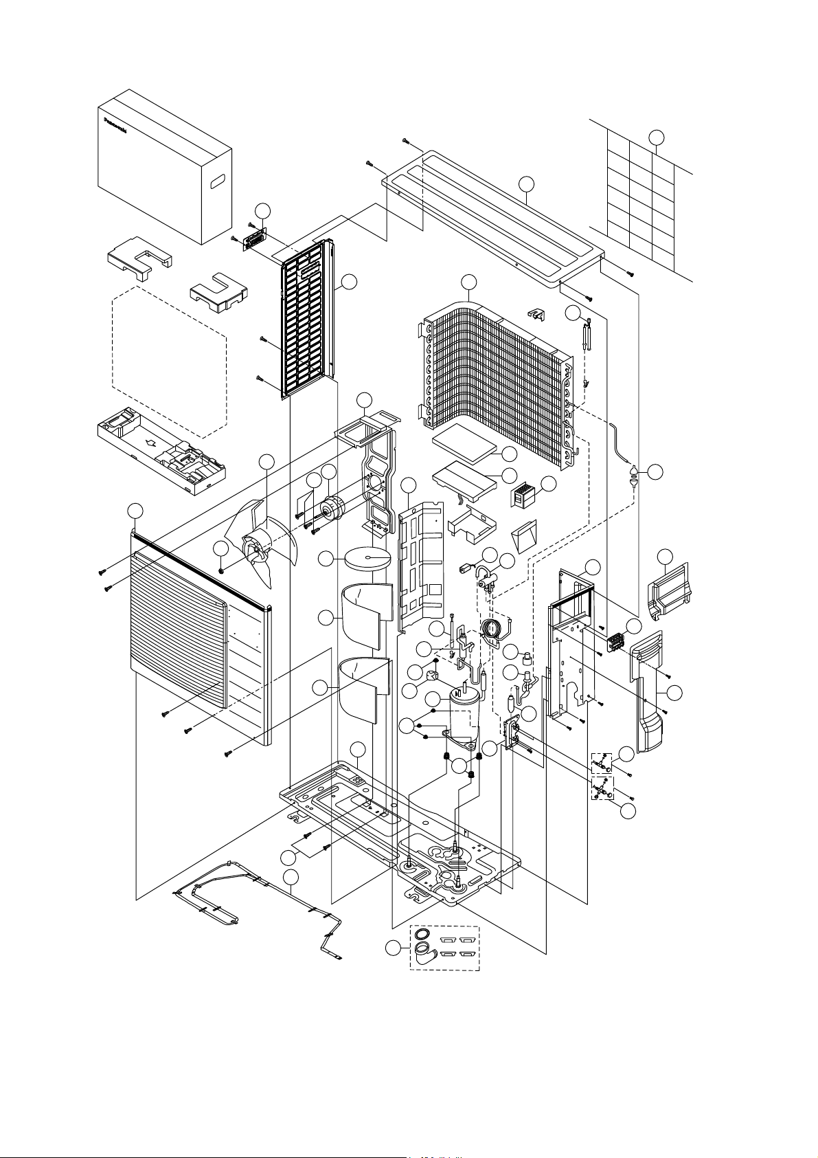
98
19.2 Outdoor Unit
Note
The above exploded view is for the purpose of parts disassembly and replacement.
The non-numbered parts are not kept as standard service parts.
x2
x2
6
10
41
40
38
9
7
22
12
47
31
27
15
30
49
67
43
33
48
20
19
11
45
42
59
5
58
1
25
24
23
3
4
62
28
14
68
18
2
8
69
70
46
99
SAFETY REF. NO. PART NAME & DESCRIPTION QTY. CU-XE9SKUA CU-XE12SKUA REMARK
1 CHASSIS COMPLETE 1 ACXD52K00130A ←
2 ANTI - VIBRATION BUSHING 3 CWH50077 ←
3 COMPRESSOR 1 5RS102XHB21 ← O
4 NUT - COMPRESSOR MOUNT 3 CWH561096 ←
5 SOUND PROOF MATERIAL 1 CWG302850 ←
6 FAN MOTOR BRACKET 1 CWD541153 ←
7 FAN MOTOR 1 ARW8407AC ← O
8 SCREW - FAN MOTOR BRACKET 2 CWH551217 ←
9 SCREW - FAN MOTOR MOUNT 4 CWH551106J ←
10 PROPELLER FAN ASSY 1 CWH03K1065 ←
11 NUT - PROPELLER FAN 1 CWH56053J ←
12 CONDENSER 1 CWB32C3796 ←
14 EXPANSION VALVE 1 CWB051016J ← O
15 4-WAYS VALVE 1 CWB001057 ← O
18 HOLDER COUPLING 1 CWH351228A ←
19 3-WAY VALVE (GAS) 1 CWB011784 CWB011785 O
20 2-WAYS VALVE (LIQUID) 1 CWB021180J ← O
22 SOUND PROOF BOARD 1 CWH151295 ←
23 TERMINAL COVER 1 CWH171039A ←
24 NUT - TERMINAL COVER 1 CWH7080300J ←
25 SENSOR CO – COMP. TEMP. 1 CWA50C2343 ← O
27 V-COIL COMPLETE (4-WAY VALVE) 1 CWA43C2392 ← O
28 V-COIL COMPLETE (EXP.VALVE) 1 CWA43C2393 ← O
30
SENSOR – COMPLETE (AIR TEMP AND PIPE
TEMP)
1 CWA50C2710 ← O
31 REACTOR 1 G0C193J00004 ← O
33 TERMINAL BOARD ASSY 1 CWA28K1154 ← O
38 ELECTRONIC CONTROLLER - MAIN 1 ACXA73C04470R ACXA73C04480R O
40 CONTROL BOARD COVER-TOP 1 CWH131333 ← O
41 CABINET SIDE PLATE (LEFT) 1 CWE041733A ←
42 HANDLE 1 CWE161010 ←
43 CABINET SIDE PLATE (RIGHT) 1 CWE041732A ←
45 CABINET FRONT PLATE CO. 1 CWE06K1101 ←
46 WIRE NET 1 CWD041155A ←
47 CABINET TOP PLATE 1 CWE031131A ←
48 CONTROL BOARD COVER - COMPLETE 1 CWH13C1308 ←
49 CONTROL BOARD COVER 1 CWH131409 ←
58 SOUND PROOF MATERIAL 1 CWG302851 ←
59 SOUND PROOF MATERIAL 1 CWG302630 ←
62 DISCHARGE MUFFLER (4-WAYS VALVE) 1 CWB121047 ←
67 STRAINER 1 CWB111076 ←
68 DISCHARGE MUFFLER (EXP. VALVE) 1 CWB121021 ←
69 HEATER 1 CWA341072 ← O
70 BAG - COMPLETE 1 ACXH82C00350 ←
(NOTE)
All parts are supplied from PAPAMY, Malaysia (Vendor Code: 00029488).
“O” marked parts are recommended to be kept in stock.
Printed in Malaysia
FY0116-0