
Owner’s manual
SEAT Tarraco
5FJ012720BD
Inglés 5FJ012720BD (11.19)
SEAT Tarraco Inglés (11.19)
SEAT Tarraco FR

SEAT S.A. is permanently concerned about continuous development of its types and models. For this reason we ask you to understand,
that at any given time, changes regarding shape, equipment and technique may take place on the car delivered. For this reason no
right at all may derive based on the data, drawings and descriptions in this current handbook.
All texts, illustrations and standards in this handbook are based on the status of information at the time of printing. Except for error or
omission, the information included in the current handbook is valid as of the date of closing print.
Re-printing, copying or translating, whether total or partial is not allowed unless SEAT allows it in written form.
SEAT reserves all rights in accordance with the “Copyright” Act.
All rights on changes are reserved.
❀
This paper has been manufactured using bleached non-chlorine cellulose.
© SEAT S.A. - Reprint: 15.11.19
Vehicle identification data
Model:
Vehicle Registration:
Vehicle identification
number:
Date of vehicle registration
or vehicle delivery:
SEAT Official Service:
Service advisor:
Telephone:
Confirmation of receipt of documentation
and vehicle keys
The following items were delivered
with the vehicle:
YES NO
On-board documentation
First key
Second key
Correct working order of all keys was
checked
Location:
Date:
Signature of owner:

Introduction
Thank you f
or your trust choosing a SEAT v
e-
hicl
e
.
With your ne
w SEAT
, you will be abl
e to enjoy
a vehicle with state-of-the-art technology
and top quality features.
We recommend reading this Instruction Man-
ual carefully to learn more about your vehicle
so you can enjoy all its benefits in your daily
driving.
Information about handling is complemented
with instructions regarding the operation and
maintenance of the vehicle in order to ensure
its safety and maintain its value. Moreover, we
want to give you valuable advice and tips to
drive your vehicle efficiently and respecting
the environment.
We wish you safe and enjoyable motoring.
SEAT, S.A.
WARNING
Read and always observe safety infor-
mation concerning the passenger's
front airbag
›››
page 32, Fitting and us-
ing child seats
.
About this manual
This manual describes the f
eat
ur
es
of the v
e-
hicl
e at the time of dr
afting this text. Some of
the features described below will be intro-
duced in the future or will only be available in
certain markets.
Some of the features described here are
not included in all the types or variations
of the model and they can be varied or
modified based on technical or marketing
requirements without it being considered
misleading advertising.
Some details on the drawings may vary from
its vehicle and must be interpreted as a
standard representation.
The direction indicators (left, right, forwards,
backwards) in this manual refer to the travel
direction of the vehicle unless otherwise sta-
ted.
The audiovisual material is only meant to
help the users better understand some fea-
tures of the car. It is not a replacement for the
instruction manual. Access the instruction
manual to see the complete information and
warnings.
The features marked with an asterisk
are included by default only in certain
versions of the model, supplied as op-
tional only for certain versions or only of-
fered in certain countries.
Trademarks are marked with ®. The ab-
sence of this symbol does not guarantee
that the term is not a trademark.
It indicates that the section continues on
the next page.
You can access the information in this manual
using:
●
Thematic table of contents that follows the
manual’s general chapter structure.
●
Visual table of contents that uses graphics
to indicate the pages containing “essential”
information, which is detailed in the corre-
sponding chapters.
●
Alphabetical index with many terms and
synonyms to help you find information.
WARNING
Texts after this symbol contain informa-
tion about safety and warn you about
possible accident or injury risks.
CAUTION
Texts after this symbol indicate possible
damage to the vehicle.
For the sake of the environment
Texts after this symbol contain informa-
tion about the protection of the environ-
ment.
®
Note
Texts after this symbol contain addition-
al information.
Printed and digital instruction man-
ual
The print
ed instruction manual cont
ains r
el
e-
v
ant inf
ormation about the use of the v
ehicle
and the Infotainment System.
The digital version of the manuals contains
more in-depth information. It is available on
SEAT's official website.
To view the digital version of the manual:
Fig. 1 SEAT website
●
scan the QR code
›
›
›
Fig. 1
●
OR
ent
er the f
oll
owing address in the navi-
gator website:
http://www.seat.com/owners/your-
seat/manuals-offline.html
and select your vehicle.
R
elated videos
The oper
ation of some of the vehicle's fea-
tures can be sho
wn as an instruction video:
Fig. 2 SEAT website
●
scan the QR code
›
›
›
Fig. 2
●
OR
ent
er the f
oll
owing address in the navi-
gator website:
http://www.seat.com/owners/your-
seat/manuals-offline.html
choose your vehicle and then “Multimedia”.
Note
Video instructions are only available in
certain languages.

Frequently Asked Ques-
tions
Before driving
How do you adjust the seat?
›››
page 123
How do you adjust the steering wheel?
››
›
page 14
How do you adjust the exterior mirr
ors?
›››
page 121
How do you turn on the e
xterior lights?
›››
page 109
How does the automatic gearbox sel
ector lever
work?
›››
page 254
How do you r
efuel?
›
›
›
page 34
2
Ho
w do you activ
at
e the windscreen wipers and
windscreen washer system?
›››
page 118
Emergency situations
A warning lamp lights up or flashes. What does
this mean?
›››
page 79
How do you open the bonnet?
›
››
page 350
How do you perform a jump st
art?
›››
page 51
Where is the vehicle t
ool kit located?
›››
page 41
How do you repair a tyre with the anti-puncture
kit?
›››
page 43
How do you change a wheel?
››
›
page 45
How do you change a fuse?
››
›
page 57
How do you change a light?
››
›
page 61
How do you to
w a vehicle?
›››
page 52
Useful tips
How do you set the time?
›››
page 75
When should the vehicle inspection shoul
d be
performed?
›››
page 77
What functions do the buttons/thumb
wheels on
the steering wheel perform?
›››
page 85
How do you r
emove the luggage compartment
cover?
›››
page 135
How do you driv
e in an economical and environ-
mentally-friendly way?
›››
page 266
How do you check and t
op up the engine oil?
›
›
›
page
352
Ho
w do you check and t
op up the engine cool
-
ant?
›››
page 355
How do you top up the windscreen washer fluid?
›››
page 357
How do you check and top up the brake fluid?
›››
page 357
How do you check and adjust tyre pr
essure val-
ues?
›››
page 365
Vehicle w
ashing tips
›››
page 376
Functions of interest
Easy Connect, Car menu
›››
page 82
How does the STAR
T-STOP system work?
›››
page 250
What parking assistants are avail
able?
›››
page 306
How does the rear assist w
ork?
›››
page 327
How does the adaptive cruise control w
ork?
›››
page 277
How can the SEAT driving mode be adjusted?
›
›
›
page
263
Ho
w does the l
ane depart
ure warning system
work?
›››
page 286
How does tyre pressure monitoring work?
›››
page 369
How do you open the vehicle without a key (Key-
less Access)?
›››
page 92
Interior lighting and ambient light
›››
page 117

Table of Contents
Table of Contents
Gener
al vie
ws of the v
ehicl
e
. . . . . . . .
7
Ext
erior view . . . . . . . . . . . . . . . . . . . . . . . . . . . . . . . 7
Overview (left hand drive) . . . . . . . . . . . . . . . . 8
Overview (right hand drive) . . . . . . . . . . . . . . . 9
Interior view . . . . . . . . . . . . . . . . . . . . . . . . . . . . . . . 10
Safety . . . . . . . . . . . . . . . . . . . . . . . . . . . . . . . . . . . . 11
Safe driving . . . . . . . . . . . . . . . . . . . . . . . . . . . . . . . 11
Advice about driving . . . . . . . . . . . . . . . . . . . . . . . . 11
Correct sitting position of vehicle occu-
pants . . . . . . . . . . . . . . . . . . . . . . . . . . . . . . . . . . . . . . . 12
Pedal area . . . . . . . . . . . . . . . . . . . . . . . . . . . . . . . . . 15
Seat belts . . . . . . . . . . . . . . . . . . . . . . . . . . . . . . . . . 16
The whys and wherefores of seat belts . . . . . 16
How to properly adjust your seat belt . . . . . . 19
Seat belt tensioners . . . . . . . . . . . . . . . . . . . . . . . . 21
PreCrash system* . . . . . . . . . . . . . . . . . . . . . . . . . . 22
Airbag system . . . . . . . . . . . . . . . . . . . . . . . . . . . . . 23
Brief introduction . . . . . . . . . . . . . . . . . . . . . . . . . . . 23
Operation of the airbags . . . . . . . . . . . . . . . . . . . 25
Transporting children safely . . . . . . . . . . . . . . 31
Safety for children . . . . . . . . . . . . . . . . . . . . . . . . . . 31
Emergencies . . . . . . . . . . . . . . . . . . . . . . . . . . . . 41
Self-help . . . . . . . . . . . . . . . . . . . . . . . . . . . . . . . . . . 41
Emergency call service* . . . . . . . . . . . . . . . . . . . 41
Emergency equipment . . . . . . . . . . . . . . . . . . . . . 41
Tyre repairs . . . . . . . . . . . . . . . . . . . . . . . . . . . . . . . . . 42
Changing a wheel . . . . . . . . . . . . . . . . . . . . . . . . . . 45
Changing the windscreen wiper blades . . . . 49
Jump start . . . . . . . . . . . . . . . . . . . . . . . . . . . . . . . . . . 51
Tow start and towing . . . . . . . . . . . . . . . . . . . . . . . 52
Fuses and bulbs . . . . . . . . . . . . . . . . . . . . . . . . . . . 57
Fuses . . . . . . . . . . . . . . . . . . . . . . . . . . . . . . . . . . . . . . . 57
Bulbs . . . . . . . . . . . . . . . . . . . . . . . . . . . . . . . . . . . . . . . 61
Operation . . . . . . . . . . . . . . . . . . . . . . . . . . . . . . . 63
Controls and displays . . . . . . . . . . . . . . . . . . . . 63
Interior view . . . . . . . . . . . . . . . . . . . . . . . . . . . . . . . . 63
Instruments and warning/control
lamps . . . . . . . . . . . . . . . . . . . . . . . . . . . . . . . . . . . . . . 64
Instrument panel . . . . . . . . . . . . . . . . . . . . . . . . . . . 64
Using the instrument panel . . . . . . . . . . . . . . . . . 78
Control lamps . . . . . . . . . . . . . . . . . . . . . . . . . . . . . . 79
Easy Connect system . . . . . . . . . . . . . . . . . . . . . . 82
Multifunction steering wheel* . . . . . . . . . . . . . . 85
Opening and closing . . . . . . . . . . . . . . . . . . . . . . 87
Set of vehicle keys . . . . . . . . . . . . . . . . . . . . . . . . . . 87
Central locking . . . . . . . . . . . . . . . . . . . . . . . . . . . . . 89
Anti-theft alarm system* . . . . . . . . . . . . . . . . . . . 96
Doors . . . . . . . . . . . . . . . . . . . . . . . . . . . . . . . . . . . . . . 98
Rear lid . . . . . . . . . . . . . . . . . . . . . . . . . . . . . . . . . . . . . 100
Window controls . . . . . . . . . . . . . . . . . . . . . . . . . . . 104
Sunroof* . . . . . . . . . . . . . . . . . . . . . . . . . . . . . . . . . . . 106
Lights . . . . . . . . . . . . . . . . . . . . . . . . . . . . . . . . . . . . . . 109
Vehicle lighting . . . . . . . . . . . . . . . . . . . . . . . . . . . . . 109
Interior lights . . . . . . . . . . . . . . . . . . . . . . . . . . . . . . . 117
Visibility . . . . . . . . . . . . . . . . . . . . . . . . . . . . . . . . . . . 118
Windscreen wiper and rear window wiper
systems . . . . . . . . . . . . . . . . . . . . . . . . . . . . . . . . . . . . 118
Mirrors . . . . . . . . . . . . . . . . . . . . . . . . . . . . . . . . . . . . . 121
Sun protection . . . . . . . . . . . . . . . . . . . . . . . . . . . . . 123
Seats and headrests . . . . . . . . . . . . . . . . . . . . . . 123
Adjusting seats . . . . . . . . . . . . . . . . . . . . . . . . . . . . . 123
Headrest . . . . . . . . . . . . . . . . . . . . . . . . . . . . . . . . . . . 125
Seat functions . . . . . . . . . . . . . . . . . . . . . . . . . . . . . . 128
Transport and practical equipment . . . . . . 134
Storing objects . . . . . . . . . . . . . . . . . . . . . . . . . . . . . 134
Luggage compartment . . . . . . . . . . . . . . . . . . . . . 135
Net partition* . . . . . . . . . . . . . . . . . . . . . . . . . . . . . . . 142
Roof carrier* . . . . . . . . . . . . . . . . . . . . . . . . . . . . . . . 143
Storage compartment . . . . . . . . . . . . . . . . . . . . . 145
Drink holder . . . . . . . . . . . . . . . . . . . . . . . . . . . . . . . . 148
Power sockets . . . . . . . . . . . . . . . . . . . . . . . . . . . . . . 150
Air conditioning . . . . . . . . . . . . . . . . . . . . . . . . . . . 152
Heating, ventilation and cooling . . . . . . . . . . . . 152
Auxiliary heating (additional heating)* . . . . . 161
Infotainment System . . . . . . . . . . . . . . . . . . 165
Introduction . . . . . . . . . . . . . . . . . . . . . . . . . . . . . . . 165
Safety warnings . . . . . . . . . . . . . . . . . . . . . . . . . . . . 165
Overview of the unit . . . . . . . . . . . . . . . . . . . . . . . . 167
General instructions for use . . . . . . . . . . . . . . . . 170
Voice control . . . . . . . . . . . . . . . . . . . . . . . . . . . . . . . 177
Connectivity . . . . . . . . . . . . . . . . . . . . . . . . . . . . . . 180
Data transfer . . . . . . . . . . . . . . . . . . . . . . . . . . . . . . . 180
Full Link* . . . . . . . . . . . . . . . . . . . . . . . . . . . . . . . . . . . 180
SEAT Media Control* . . . . . . . . . . . . . . . . . . . . . . . 186
WLAN access point* . . . . . . . . . . . . . . . . . . . . . . . . 187
Operating modes . . . . . . . . . . . . . . . . . . . . . . . . . 190
Radio . . . . . . . . . . . . . . . . . . . . . . . . . . . . . . . . . . . . . . . 190
Media . . . . . . . . . . . . . . . . . . . . . . . . . . . . . . . . . . . . . . 198
Navigation . . . . . . . . . . . . . . . . . . . . . . . . . . . . . . . . . 215
Navigation in Offroad mode* . . . . . . . . . . . . . . . 227
Vehicle Menu . . . . . . . . . . . . . . . . . . . . . . . . . . . . . . . 229
Telephone . . . . . . . . . . . . . . . . . . . . . . . . . . . . . . . . . . 233
Multimedia . . . . . . . . . . . . . . . . . . . . . . . . . . . . . . . . . 244
5

Table of Contents
Driving . . . . . . . . . . . . . . . . . . . . . . . . . . . . . . . . . . . 246
Start and driving . . . . . . . . . . . . . . . . . . . . . . . . . . 246
Starting and stopping the engine . . . . . . . . . . . 246
Start-Stop system* . . . . . . . . . . . . . . . . . . . . . . . . . 250
Manual gearbox . . . . . . . . . . . . . . . . . . . . . . . . . . . . 253
Automatic gearbox/DSG automatic gear-
bo
x* . . . . . . . . . . . . . . . . . . . . . . . . . . . . . . . . . . . . . . . .
254
Gear
-change r
ecommendation . . . . . . . . . . . .
261
Hill Descent Contr
ol (HDC) . . . . . . . . . . . . . . . . .
261
Steering . . . . . . . . . . . . . . . . . . . . . . . . . . . . . . . . . . . . 262
SEAT Driving modes (SEAT Drive Pro-
file)* . . . . . . . . . . . . . . . . . . . . . . . . . . . . . . . . . . . . . . . . 263
Driving tips . . . . . . . . . . . . . . . . . . . . . . . . . . . . . . . . . 265
Driver assistance systems . . . . . . . . . . . . . . . . 268
Cruise control system (CCS)* . . . . . . . . . . . . . . 268
Speed limiter . . . . . . . . . . . . . . . . . . . . . . . . . . . . . . . 270
Emergency brake assistance system (Front
Assist)* . . . . . . . . . . . . . . . . . . . . . . . . . . . . . . . . . . . . . 273
ACC - Adaptive Cruise Control* . . . . . . . . . . . 277
Lane Assist* . . . . . . . . . . . . . . . . . . . . . . . . . . . . . . . . 286
Traffic Jam Assist . . . . . . . . . . . . . . . . . . . . . . . . . . . 289
Emergency Assist . . . . . . . . . . . . . . . . . . . . . . . . . . . 290
Using the blind spot detector (BSD) with
parking assistant (RCTA)* . . . . . . . . . . . . . . . . . . 291
Braking and parking . . . . . . . . . . . . . . . . . . . . . . . 297
Braking system . . . . . . . . . . . . . . . . . . . . . . . . . . . . . 297
Stabilisation and brake assistance sys-
tems . . . . . . . . . . . . . . . . . . . . . . . . . . . . . . . . . . . . . . . . 302
Parking . . . . . . . . . . . . . . . . . . . . . . . . . . . . . . . . . . . . . 305
Help with parking and manoeuvring . . . . . 306
Assisted parking system (Park Assist)* . . . . . . 306
Parking aid parking and manoeuvring
(ParkPilot) . . . . . . . . . . . . . . . . . . . . . . . . . . . . . . . . . . 314
Parking System Plus* . . . . . . . . . . . . . . . . . . . . . . . 315
Rear parking aid* . . . . . . . . . . . . . . . . . . . . . . . . . . 319
Trailer Assist . . . . . . . . . . . . . . . . . . . . . . . . . . . . . . . . 320
Peripheral view system (Top View Cam-
era)* . . . . . . . . . . . . . . . . . . . . . . . . . . . . . . . . . . . . . . . 323
Reverse Assist (Rear View Camera)* . . . . . . . 327
Towing bracket device* . . . . . . . . . . . . . . . . . . . 332
Trailer mode . . . . . . . . . . . . . . . . . . . . . . . . . . . . . . . . 332
Electrically unlocking trailer hook* . . . . . . . . . 339
Retrofitting a towing bracket . . . . . . . . . . . . . . . 340
Practical tips . . . . . . . . . . . . . . . . . . . . . . . . . . . 342
Checking and refilling levels . . . . . . . . . . . . . 342
Refuelling . . . . . . . . . . . . . . . . . . . . . . . . . . . . . . . . . . 342
Fuel types . . . . . . . . . . . . . . . . . . . . . . . . . . . . . . . . . . 343
AdBlue
®
. . . . . . . . . . . . . . . . . . . . . . . . . . . . . . . . . . . . 345
Engine management and emissions control
system . . . . . . . . . . . . . . . . . . . . . . . . . . . . . . . . . . . . . 347
Engine compartment . . . . . . . . . . . . . . . . . . . . . . . 349
Engine oil . . . . . . . . . . . . . . . . . . . . . . . . . . . . . . . . . . . 352
Cooling system . . . . . . . . . . . . . . . . . . . . . . . . . . . . 355
Brake fluid . . . . . . . . . . . . . . . . . . . . . . . . . . . . . . . . . . 357
Windscreen washer reservoir . . . . . . . . . . . . . . . 357
Battery . . . . . . . . . . . . . . . . . . . . . . . . . . . . . . . . . . . . . 358
Energy management . . . . . . . . . . . . . . . . . . . . . . . 361
Wheels . . . . . . . . . . . . . . . . . . . . . . . . . . . . . . . . . . . . 363
Wheels and tyres . . . . . . . . . . . . . . . . . . . . . . . . . . . 363
Tyre pressure loss indicator . . . . . . . . . . . . . . . . . 369
Spare wheel . . . . . . . . . . . . . . . . . . . . . . . . . . . . . . . . 371
Maintenance . . . . . . . . . . . . . . . . . . . . . . . . . . . . 373
SEAT Maintenance Programme . . . . . . . . . . 373
Service intervals . . . . . . . . . . . . . . . . . . . . . . . . . . . . 373
Additional service offers . . . . . . . . . . . . . . . . . . . . 375
Warranty . . . . . . . . . . . . . . . . . . . . . . . . . . . . . . . . . . . 376
Vehicle maintenance . . . . . . . . . . . . . . . . . . . . . 376
Maintenance and cleaning . . . . . . . . . . . . . . . . . 376
Accessories and modifications to the ve-
hicle . . . . . . . . . . . . . . . . . . . . . . . . . . . . . . . . . . . . . . . 381
Accessories, spare parts and repair work . . . 381
Information for the user . . . . . . . . . . . . . . 384
Information for the user . . . . . . . . . . . . . . . . . . . 384
Information stored by the control units . . . . . . 384
Other important information . . . . . . . . . . . . . . . . 384
Information about the EU Directive
2014/53/EU . . . . . . . . . . . . . . . . . . . . . . . . . . . . . . . . 385
Technical data . . . . . . . . . . . . . . . . . . . . . . . . . 389
Indications about the technical data . . . . 389
Important information . . . . . . . . . . . . . . . . . . . . . . 389
Index . . . . . . . . . . . . . . . . . . . . . . . . . . . . . . . . . . . . . . 395
6
General views of the vehicle
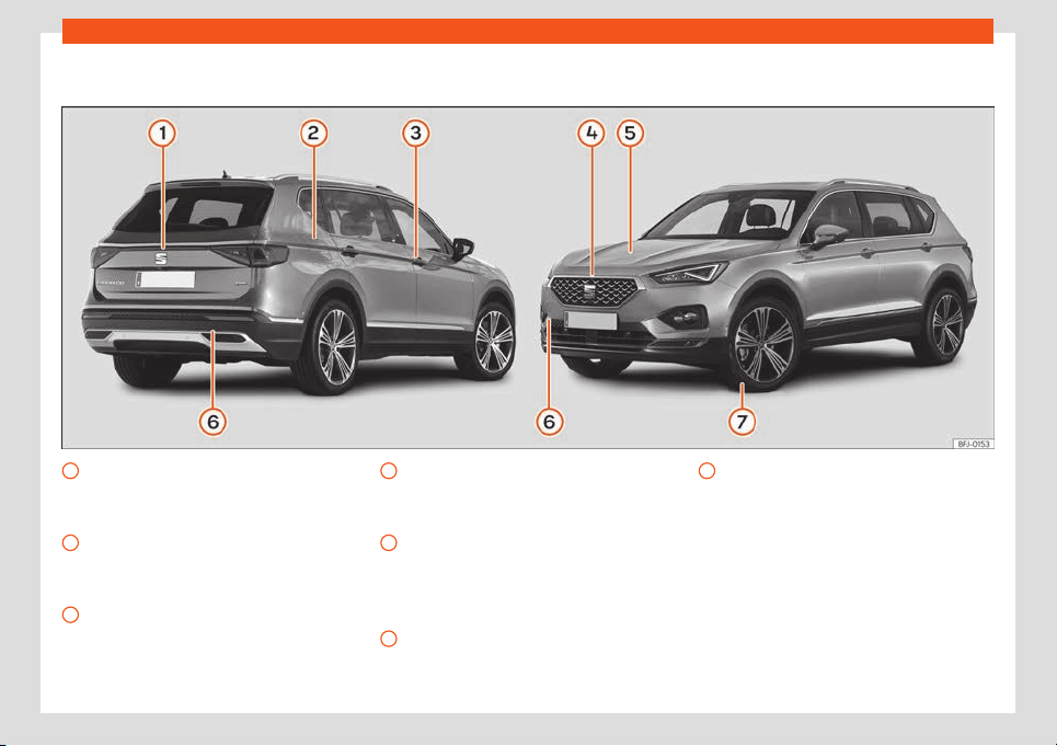
Exterior view
Rear lid
– Opening fr
om outside
›
›
›
page 101
– Emer
gency opening
›
›
›
page 104
Fuel tank
– Fuel capacity
›››
page 389
– Open/Close cap
›››
page 342
Opening and closing
– Doors
›››
page 98
– Central locking
›››
page 89
– Manual release
›››
page 99
1
2
3
Bonnet
– Unl
ocking l
e
v
er
›
›
›
page 350
– Open/close
›››
page 350
Levels control
– Oil
›››
page 352
– Brake fluid
›››
page 357
– Battery
›››
page 358
Towing the vehicle
– Towline anchorage
›››
page 55
– Tow start
›››
page 53
4
5
6
Action in the event of a puncture
– Anti-punct
ur
e kit
›
›
›
page 4
2
– Wheel change
›
››
page 45
7
7
General views of the vehicle
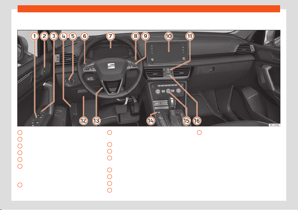
Overview (left hand drive)
Electric windows
›
›
›
page 104
Centr
al l
ocking
›
›
›
page 89
Exterior mirror adjustment
›››
page 121
Open bonnet lever
›››
page 350
Headlight switch
›››
page 110
Turn signal and main beam lever
›››
page 112
Cruise control
›››
page 268
Warning lamps
›››
page 79
1
2
3
4
5
6
7
Wipers and rear window wiper
›
›
›
page 1
18
Driv
er inf
ormation syst
em
›››
page 78
Easy Connect
›››
page 82
Front passenger airbag disconnection
display
›››
page 27
Fuses
›››
page 57
Steering wheel adjustment
›››
page 14
Starter button
›››
page 246
Air conditioning
›››
page 152
8
9
10
11
12
13
14
15
Hazard warning lights
›
›
›
page 1
15
16
8
General views of the vehicle
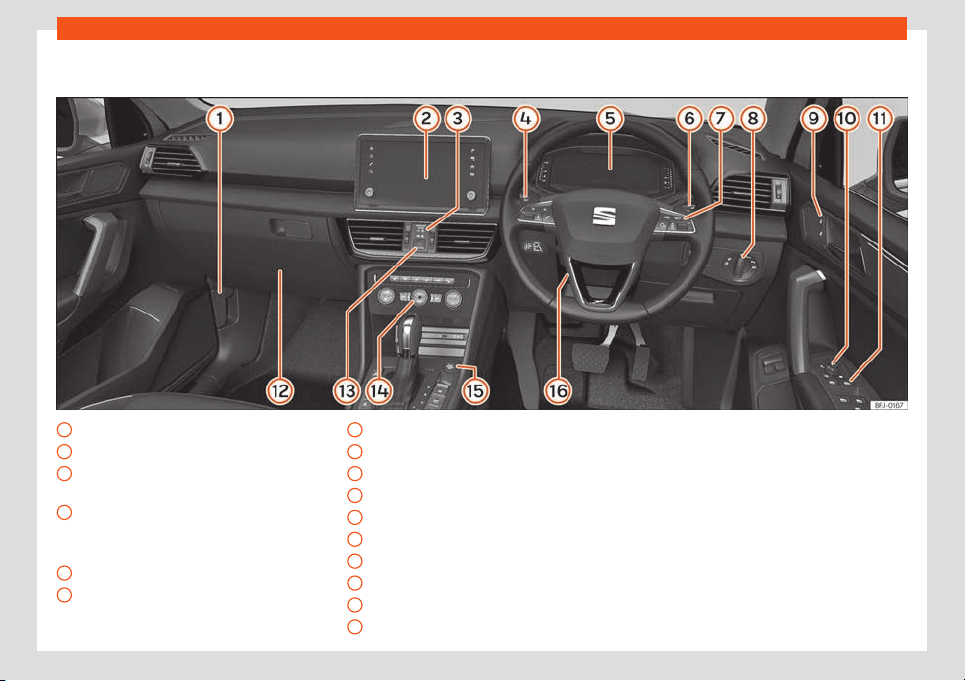
Overview (right hand drive)
Open bonnet lever
›
›
›
page 350
Easy Connect
›
›
›
page 82
Fr
ont passenger airbag disconnection
display
›››
page 27
Turn signal and main beam lever
›››
page 112
Cruise control
›››
page 268
Warning lamps
›››
page 79
Wipers and rear window wiper
›››
page 118
1
2
3
4
5
6
Driver information system
›
›
›
page 7
8
Headlight s
wit
ch
›
››
page 110
Central locking
›››
page 89
Exterior mirror adjustment
›››
page 121
Electric windows
›››
page 104
Fuses
›››
page 57
Hazard warning lights
›››
page 115
Air conditioning
›››
page 152
Starter button
›››
page 246
Steering wheel adjustment
›››
page 14
7
8
9
10
11
12
13
14
15
16
9
General views of the vehicle
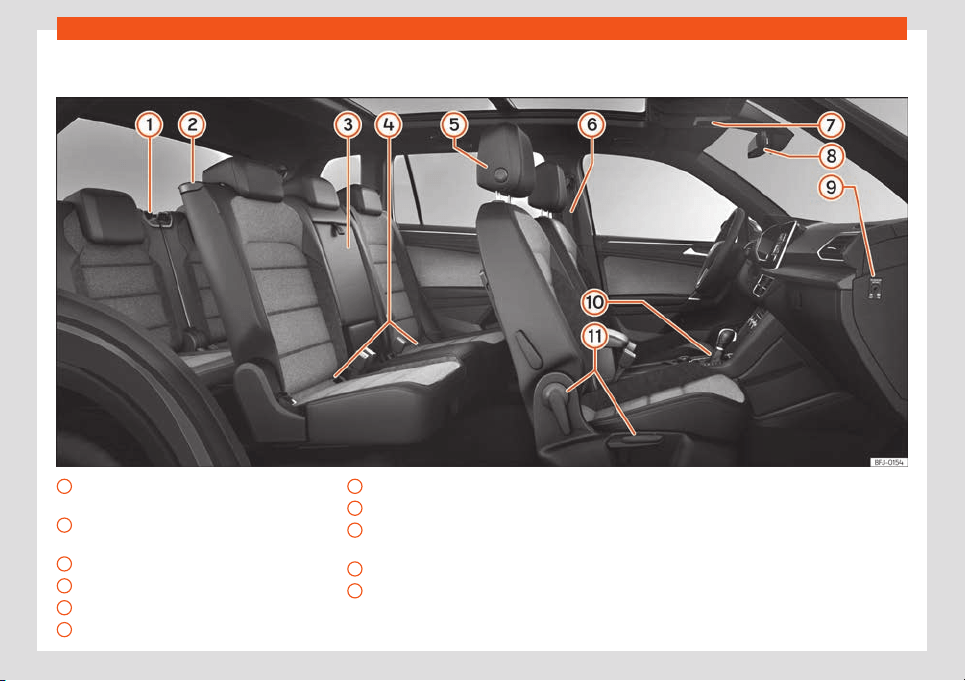
Interior view
Folding the third row of seats
›
›
›
page 137
Access t
o the thir
d r
o
w of seats
›››
page 129
Armrest
›››
page 133
Isofix anchors
›››
page 34
Headrest adjustment
›››
page 125
Seat belts
›››
page 16
1
2
3
4
5
6
Panoramic roof
›
›
›
page 106
Int
erior mirr
or
›
›
›
page 121
Disconnecting the front passenger front
airbag
›››
page 27
Electronic parking brake
›››
page 299
Seat adjustment
›››
page 123
7
8
9
10
11
10
Safe driving
Safety
Saf
e driving
Advice about driving
Saf
et
y first
!
WARNING
●
This manual contains important informa-
tion about the operation of the vehicl
e,
both for the driver and the passengers. The
other sections of the on-board documenta-
tion also contain further information that
you should be aware of for your own safety
and for the safety of your passengers.
●
Ensure that the on-board documentation
is kept in the vehicle at all times. This is es-
pecially important when lending or selling
the vehicle to another person.
Before driving
For your own safety and the safety of your
passengers, al
w
ays not
e the f
oll
o
wing points
bef
ore every trip:
–
Make sure that the vehicle's lights and turn
signals are working properly.
–
Check tyre pressure.
–
Ensure that all windows provide a clear and
good view of the surroundings.
–
Make sure all luggage is secured
›››
page 134.
–
Make sure that no objects can interfere with
the pedals.
–
Adjust front seat, headrest and mirrors
properly according to your size.
–
Ensure that the passengers in the rear seats
always have the headrests in the in-use po-
sition
›››
page 125.
–
Instruct passengers to adjust the headrests
according to their height.
–
Protect children with appropriate child
seats and properly applied seat belts
›››
page 31.
–
Assume the correct sitting position. Instruct
your passengers also to assume a proper
sitting position
›››
page 12.
–
Fasten your seat belt securely. Instruct your
passengers also to fasten their seat belts
properly
›››
page 16.
Factors influencing safety
As a driver, you are responsible for yourself
and your passengers.
–
Al
w
ays pay att
ention t
o tr
affic and do not
get distr
act
ed by passengers or telephone
calls.
–
Never drive when your driving ability is im-
paired (e.g. by medication, alcohol, drugs).
–
Observe traffic laws and speed limits.
–
Always reduce your speed as appropriate
for road, traffic and weather conditions.
–
When travelling long distances, take breaks
regularly - at least every two hours.
–
If possible, avoid driving when you are tired
or stressed.
WARNING
Driving under the influence of alcohol,
drugs, medication or narcotics may result
in severe accidents and ev
en loss of life.
●
Alcohol, drugs, medication and narcotics
may significantly alter perception, affect
reaction times and safety while driving,
which could result in the loss of control of
the vehicle.
Safety equipment
Never put your safety or the safety of your
passengers in danger
. In the e
v
ent of an acci-
dent, the saf
et
y equipment may r
educe the
»
1
1
Safety
risk of injury. The following points cover part
of the saf
et
y equipment in your SEAT
1)
:
●
thr
ee-point seat belts,
●
belt t
ension limit
ers f
or the fr
ont and rear
side seats,
●
belt tensioners for the front and rear side
seats,
●
Belt height adjustment for the front seats
●
front airbags,
●
knee airbags,
●
side airbags in the front seat backrests,
●
head-protection airbags,
●
“i-Size” anchor points for child seats in the
rear side seats and front passenger seat with
the “i-Size” system,
●
height-adjustable front headrests,
●
rear headrests with in-use position and
non-use position,
●
adjustable steering column.
The safety equipment mentioned above
works together to provide you and your pas-
sengers with the best possible protection in
the event of an accident. However, these
safety systems can only be effective if you
and your passengers are sitting in a correct
position and use this equipment properly.
Safety is everyone's business!
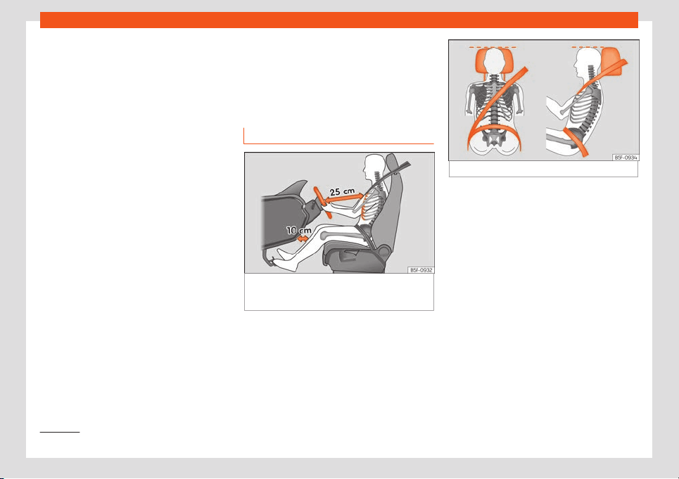
Correct sitting position of
vehicle occupants
Correct position on the seat
Fig. 3
The correct distance between the driver
and the st
eering wheel must be at l
east 25 cm
(10 inches).
Fig. 4 Correct belt web and headrest positions
The correct sitting positions for the driver and
passengers ar
e sho
wn bel
o
w
.
If your physical constit
ution pr
events you
from maintaining the correct sitting position,
contact a specialised workshop for help with
any special devices. The seat belt and airbag
can only provide optimum protection if a cor-
rect sitting position is adopted. SEAT recom-
mends taking your car in for technical serv-
ice.
For your own safety and to reduce the risk of
injury in the event of an accident or sudden
braking or manoeuvre, SEAT recommend the
following positions:
Valid for all vehicle occupants:
●
Adjust the headrest so that its upper edge is
at the same level as the top of your head, or
1)
Depending on the version/market.
12
Safe driving
as close as possible to the same level as the
t
op of your head and under no cir
cumst
ances
bel
o
w eye l
e
vel. Keep the back of your neck
as close as possible to the headrest
›››
Fig. 4.
●
Short people must lower the headrest com-
pletely, even if your head is below its upper
edge.
●
Tall people must raise the headrest com-
pletely.
●
Always keep your feet in the footwell while
the vehicle is in motion.
●
Adjust and fasten your seat belt correctly
›››
page 19.
The following also applies to the driver:
●
Given that the vehicle is equipped with ad-
justable headrests, move the headrest as
close as possible to the rear of the head.
●
Move the seat backrest to an almost up-
right position so that your back rests com-
pletely against it.
●
Move the steering wheel so it is at least
25 cm (10 inches) away from the sternum
›››
Fig. 3 and you can hold it with both hands
on both sides, on the outer part, with your
arms slightly bent.
●
The steering wheel must always point to-
wards the chest and never towards the face.
●
Move the seat in such a way that you can
step on the pedals with your knees slightly
bent and with a distance between the knees
and the dashboard of at least 10 cm (4 in-
ches)
›››
Fig. 3.
●
Adjust the height of the seat so that you
can reach the top of the steering wheel.
●
Always keep both feet in the footwell so
that you have the vehicle under control at all
times.
For the passenger, the following applies:
●
Given that the vehicle is equipped with ad-
justable headrests, move the headrest as
close as possible to the rear of the head.
●
Move the seat backrest to an almost up-
right position so that your back rests com-
pletely against it.
●
Move the seat as far back as possible (mini-
mum 25 cm between the chest and the dash-
board check translation). If you are sitting
closer than 25 cm, the airbag system cannot
protect you properly.
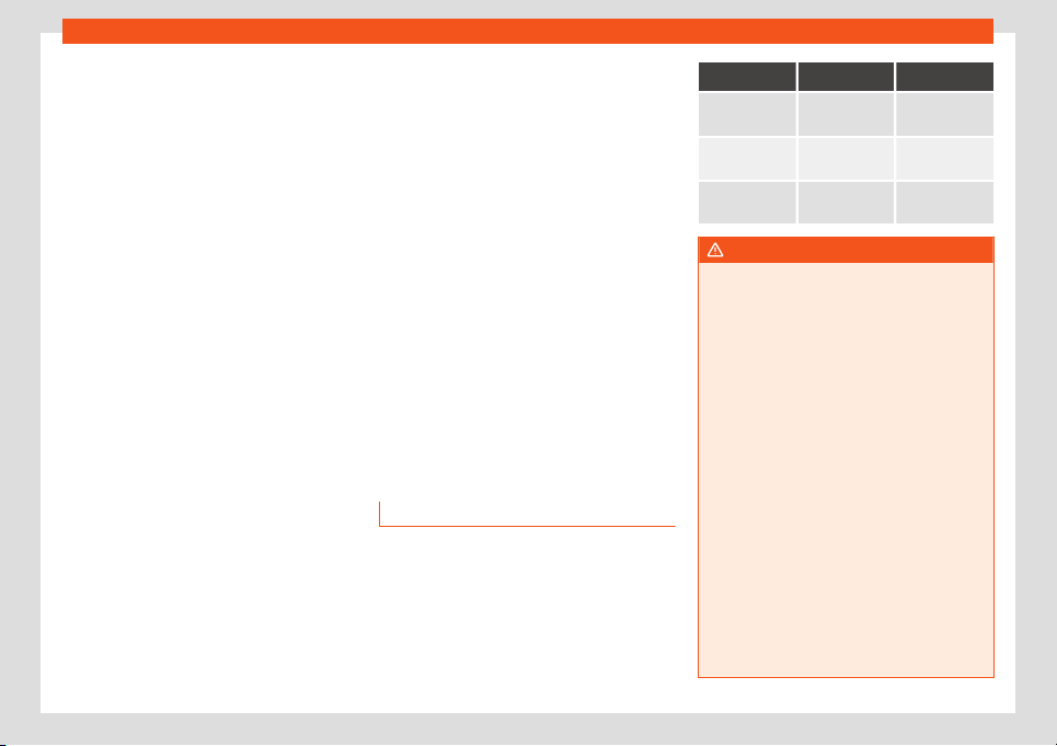
Number of seats
The vehicle has 5 or 7 seats, depending on
the f
eat
ur
es. All seats ar
e equipped with a
saf
et
y belt.
No one t
aller than 1.60 m should sit on the
third row of seats.
5 seats 7 seats
Seats in the
front
2 2
Seats in the
second row
3 3
Seats in the
third row
– 2
WARNING
Sitting in an incorrect position may in-
crease the risk of severe or lethal injuries in
the event of sudden braking or manoeu-
vring, in case of collision or accident and if
the airbags deploy.
●
Before starting the car, all passengers
must be sitting in a correct position and
stay like that for the entire journey. This al-
so applies to a correct use of the seat belt.
●
The maximum amount of people in the
vehicle is the same as the amount of seats
with seat belts.
●
For children, always use a certified pro-
tection system, certified and suited for their
weight and height
›››
page 31.
●
While driving, always keep your feet in
the footwell. Never place them over the
seat or the dashboard, for example, or out-
side the window. Otherwise the airbag and
seat belt may offer insufficient protection
and also increase the risk of injury in the
event of an accident.
»
13
Safety
WARNING
Risk of suffering severe head injuries If peo-
ple taller than 1.60 m travel in the thir
d row,
they may receive severe head injuries in
the event of an accident.
●
Never travel with anyone taller than 1.60
m on the third row.
●
When closing the rear lid, always be
mindful of the passengers of the rearmost
seats.
Risks of sitting in an incorrect posi-
tion
If seat belts are worn incorrectly or not at all,
the risk of se
v
er
e or l
ethal injuries incr
eases.
Seat belts can pr
o
vide optimal protection on-
ly if the belt web is properly worn. Incorrect
sitting positions substantially reduce the pro-
tective function of seat belts and, therefore,
increase the risk of severe or even lethal inju-
ries. The risk of severe or fatal injuries is espe-
cially heightened when a deploying airbag
strikes a vehicle occupant who has assumed
an incorrect sitting position. The driver is re-
sponsible for all people, particularly children,
inside the vehicle.
The following list contains examples of incor-
rect sitting positions that could be dangerous
for all vehicle occupants.
When the vehicle is in motion:
●
Never stand in the vehicle.
●
Never stand on the seats.
●
Never kneel on the seats.
●
Never tilt your seat backrest too far to the
rear.
●
Never lean against the dash panel.
●
Never lie on the rear seats.
●
Never sit on the front edge of a seat.
●
Never sit sideways.
●
Never lean out of a window.
●
Never put your feet out of a window.
●
Never put your feet on the dash panel.
●
Never place your feet on the bench or on
the backrest of the seat.
●
Never travel in a footwell.
●
Never sit on the armrests.
●
Never travel without wearing the seat belt.
●
Never travel in the luggage compartment.
WARNING
Sitting in an incorrect position increases
the risk of severe or fatal injuries in the
ev
ent of accidents and sudden braking or
manoeuvres.
●
All occupants must sit correctly during
the journey and wear the seat belt correct-
ly.
●
Occupants of the vehicle that are not sit-
ting correctly, not wearing the seat belt or
ar
e not at a proper distance of the airbag
risk suffering very serious or lethal injuries,
especially if the airbags deploy and strike
them.
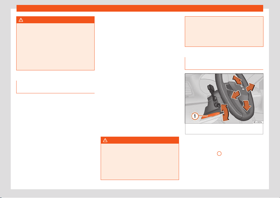
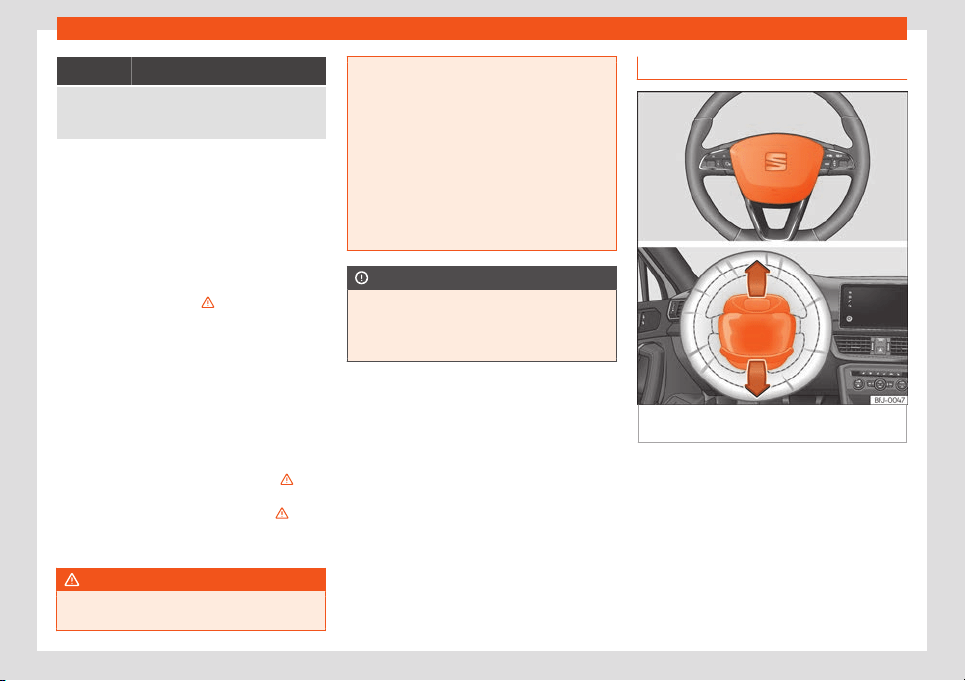
Steering wheel position adjust-
ment
Fig. 5
Lever in the lower left side of the steering
column.
Adjust the steering wheel before your trip and
only when the v
ehicl
e is st
ationary.
●
Pull the
›
›
›
Fig. 5
1
lever down, move the
st
eering wheel t
o the desir
ed position and lift
the l
e
v
er back up until it l
ocks.
14
Safe driving
WARNING
Incorrect use of the steering wheel adjust-
ment function and an incorrect adjustment
of the steering wheel can result in severe or
f
atal injury.
●
After adjusting the steering column, push
the lever
›››
Fig. 5
1
firmly upwards to en-
sure the steering wheel does not acciden-
tally change position while driving.
●
Never adjust the st
eering wheel while the
vehicle is in motion. If you need to adjust
the steering wheel while the vehicle is in
motion, stop safely and make the proper
adjustment.
●
The adjusted steering wheel should be
facing your chest and not your face so as
not to hinder the driver's front airbag pro-
tection in the event of an accident.
●
When driving, always hold the steering
wheel with both hands on the outside of the
ring at the 9 o'clock and 3 o'clock positions
to reduce injuries when the driver's front
airbag deploys.
●
Never hold the steering wheel at the 12
o'clock position or in any other manner
(e.g. in the centre of the steering wheel). In
such cases, if the driver's airbag deploys,
you may sustain injuries to your arms,
hands and head.
Pedal area
P
edal
s
–
Ensure that you can always press the ac-
celerator, brake and clut
ch pedals unim-
paired to the floor.
–
Ensure that the pedals can return unim-
paired to their initial positions.
–
Ensure that the floor mats are securely fas-
tened during the trip and do not obstruct
the pedals
›››
.
Only use fl
oor mats which l
eav
e the pedal
s
cl
ear and which ar
e secur
ed to prevent them
from slipping. You can obtain suitable floor
mats from a specialised dealership. Fasten-
ers* for floor mats are fitted in the footwells.
If a brake circuit fails, the brake pedal must be
pressed down thoroughly in order to stop the
vehicle.
Wear suitable footwear
Always wear shoes which support your feet
properly and give you a good feeling for the
pedals.
WARNING
●
Restricting pedal operation can lead to
critical situations while driving.
●
Never lay or fit floor mats or other floor
cov
erings over the original floor mats. This
would reduce the pedal area and could ob-
struct the pedals. Risk of accident.
●
Never place objects in the driver footwell.
An object could move into the pedal area
and impair pedal operation.
15
Safety
Seat belts
The whys and wher
ef
or
es of
seat belts
Contr
ol l
amps
It lights up red
Driver or passenger has not fastened seat belt.
The control lamp lights up t
o r
emind the
driv
er t
o f
ast
en their seat belt.
Bef
ore starting the vehicle:
●
Fasten your seat belt securely.
●
Instruct your passengers to fasten their
seat belts properly before driving off.
●
Protect children by using a child seat ac-
cording to the child's height and weight
›››
page 31.
When starting to drive, if the vehicle's speed
exceeds approx. 25 km/h (15 mph) and the
seat belts are not fastened or are unfastened
while driving, a warning sound will be heard
for a few seconds. The warning light will also
flash .
The lamp goes out when the driver and
passenger seat belts are fastened with the
ignition switched on.
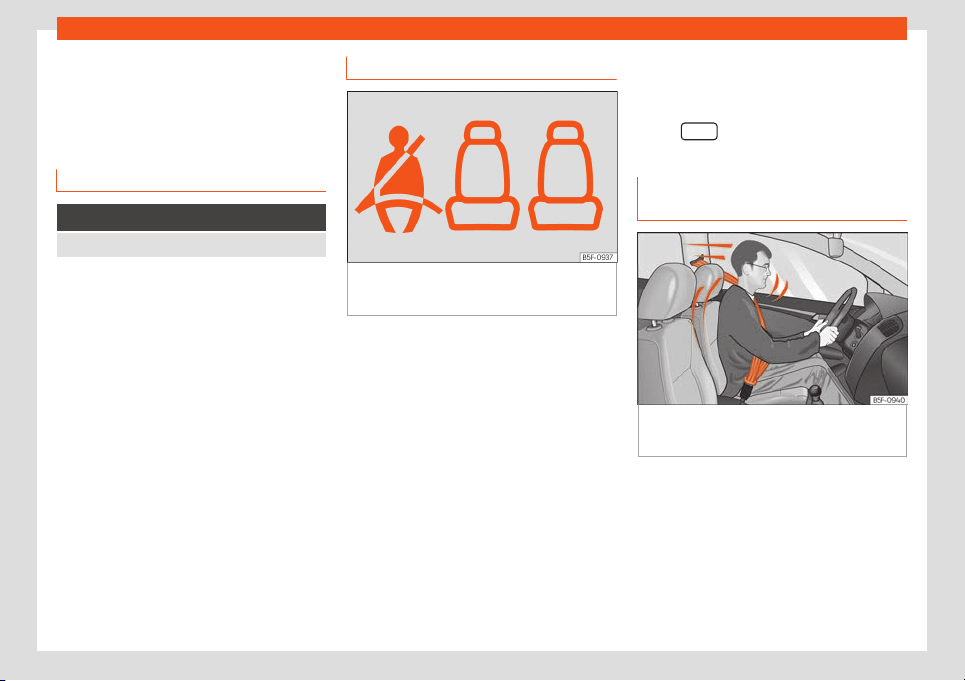
Rear seat belts fastened display*
Fig. 6
Instrument panel: left rear seat occu-
pied and corr
esponding seat belt f
ast
ened dis-
pl
ay.
Depending on the model version, when the
ignition is s
wit
ched on, the seat belt st
at
us
displ
ay
›
›
›
Fig. 6 on the instrument panel in-
forms the driver whether the passengers in
the rear seats have fastened their seat belts.
It indicates that the corresponding seat
is empty.
A green light indicates that the seat is
occupied and the occupant is wearing
the seat belt.
A red light indicates that the seat is oc-
cupied and the occupant is not wearing
the seat belt. In this case, the seat belt
control lamp will also light up in red and,
if driving over 25 km/h (15 mph), a warn-
ing sound will be emitted for a few sec-
onds.
If a seat belt is fastened or unfastened while
driving in some of the rear seats, the seat belt
status is displayed for approximately 30 sec-
onds. The indication can be hidden by press-
ing the
button on the dash panel.
The protective function of seat
belts
Fig. 7 Drivers with properly worn seat belts will
not be thr
o
wn f
orw
ar
d in the e
v
ent of sudden
braking.
Properly worn seat belts hold the occupants
in the pr
oper position. They al
so help pr
e
v
ent
uncontr
oll
ed movements that may result in
serious injury and reduce the risk of being
thrown out of the vehicle in case of an acci-
dent.
Vehicle occupants wearing their seat belts
correctly benefit greatly from the ability of
the belts to absorb kinetic energy. In addition,
16
Seat belts
the front part of your vehicle and other pas-
siv
e saf
et
y f
eat
ur
es (such as the airbag sys-
t
em) are designed to absorb the kinetic ener-
gy released in a collision. Taken together, all
these features reduce the releasing kinetic
energy and consequently, the risk of injury.
This is why it is so important to fasten seat
belts before every trip, even when "just driving
around the corner".
Ensure that your passengers wear their seat
belts as well. Accident statistics have shown
that wearing seat belts is an effective means
of substantially reducing the risk of injury and
improving the chances of survival when in-
volved in a serious accident. Furthermore,
properly worn seat belts improve the protec-
tion provided by airbags in the event of an
accident. For this reason, wearing a seat belt
is required by law in most countries.
Although your vehicle is equipped with air-
bags, the seat belts must be fastened and
worn. The front airbags, for example, are only
triggered in some cases of head-on collision.
The front airbags will not be triggered during
minor frontal or side collisions, rear-end colli-
sions, overturns or accidents in which the air-
bag trigger threshold value in the control unit
is not exceeded.
Important safety instructions for
the use of seat belts
–
Always wear the seat belt as described in
this section.
–
Ensure that the seat belts can be fastened
at all times and are not damaged.
WARNING
●
If seat belts are worn incorrectly or not at
all, the risk of severe injuries incr
eases. The
optimal protection from seat belts can be
achieved only if you use them properly.
●
Never allow two passengers (even chil-
dren) to share the same seat belt.
●
Never unbuckle a seat belt while the ve-
hicle is in motion. Risk of fatal injury.
●
The seat belt should never lie on hard or
fragile objects (such as glasses or pens,
etc.) because this can cause injuries.
●
Do not allow the seat belt to be damaged
or jammed, or to rub on any sharp edges.
●
Never wear the seat belt under the arm or
in any other incorrect position.
●
Bulky and unfastened clothing (such as
an overcoat over a sweater) impairs the
proper fit and function of the seat belts, re-
ducing their capacity to protect.
●
The slot in the seat belt buckle must not
be blocked with paper or other objects, as
this can prevent the latch plate from en-
gaging securely.
●
Never use seat belt clips, fastening rings
or similar items t
o alter the position of the
belt webbing.
●
Frayed or torn seat belts or damage to
the connections, belt retractors or parts of
the buckle could cause severe injuries in
the event of an accident. Therefore, you
must check the condition of all seat belts
at regular intervals.
●
Seat belts which have been worn in an
accident and have been stretched must be
replaced by a specialised workshop. Re-
newal may be necessary even if there is no
apparent damage. The belt anchorage
should also be checked.
●
Do not attempt to repair a damaged seat
belt yourself. The seat belts must not be re-
moved or modified in any way.
●
The belts must be kept clean, otherwise
the retractors may not work properly.
17

Safety
Head-on collisions and the laws of
physics
Fig. 8
A driver not wearing a seat belt is thrown
f
orw
ar
d viol
ently.
Fig. 9
The unbelted passenger in the rear seat
is thr
o
wn f
orw
ar
d viol
ently, hitting the driv
er
who is wearing a seat belt.
The effects of the laws of physics in the case
of a head-on collision ar
e easy t
o e
xpl
ain: the
moment a v
ehicl
e st
arts moving, a type of en-
ergy called “kinetic energy” starts acting on
both the vehicle and its passengers.
The amount of “kinetic energy” depends on
the speed of the vehicle and on the weight of
the vehicle and of its passengers. The higher
they are, the more energy there is to be “ab-
sorbed” in the event of an accident.
The most significant factor, however, is the
speed of the vehicle. If the speed doubles
from 25 km/h (15 mph) to 50 km/h (30 mph),
for example, the corresponding kinetic ener-
gy is multiplied by four.
Given that the passengers of the vehicle in
our example do not have their seat belts fas-
tened, in the event of a collision the entire
amount of the passengers' kinetic energy will
be only absorbed by the mentioned impact.
Even at speeds of 30 km/h (19 mph) to
50 km/h (30 mph), the forces acting on bod-
ies in a collision can easily exceed one tonne
(1000 kg). At greater speed these forces are
even higher.
Vehicle occupants not wearing seat belts are
not “attached” to the vehicle. In a head-on
collision, they will move forward at the same
speed their vehicle was travelling just before
the impact. This example applies not only to
head-on collisions, but to all accidents and
collisions.
Even at low speeds the forces acting on the
body in a collision are so great that it is not
possible to brace oneself with one's hands. In
a frontal collision, unbelted passengers are
thrown forward and will make violent contact
with the steering wheel, dash panel, wind-
screen or whatever else is in the way
›››
Fig. 8.
It is also important for rear passengers to
wear seat belts properly, as they could other-
wise be thrown forward violently through the
vehicle interior in an accident. Passengers in
the rear seats who do not use seat belts en-
danger not only themselves but also the front
occupants
›››
Fig. 9.
18
Seat belts
How to properly adjust your
seat belt
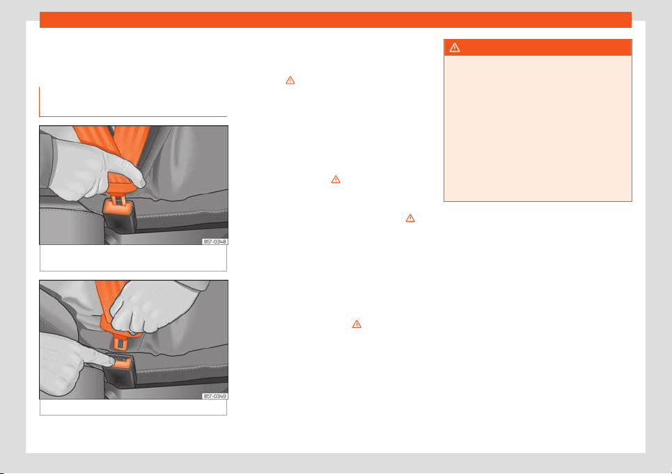
F
ast
ening and unf
ast
ening the seat
belt
Fig. 10 Insert the latch plate of the seat belt
int
o the buckl
e
.
Fig. 11 Release the seat belt's buckle.
Properly worn seat belts hold the vehicle oc-
cupants in the position that most pr
ot
ects
them in the e
v
ent of an accident or sudden
br
aking
›
›
›
.
F
ast
ening the seat belt
F
ast
en your seat belt bef
or
e each trip
.
●
Adjust the front seat and headrest correctly
›››
page 12.
●
Engage the seat backrest of the rear seat in
an upright position
›››
.
●
Pull the latch plate and place the belt web-
bing e
v
enly acr
oss your chest and l
ap
. Do
not
twist the seat belt when doing so
›
››
.
●
Engage the latch plate in the buckle of the
corr
esponding seat
›
›
›
Fig. 10
.
●
Pull the belt t
o ensur
e that the latch plate is
securely engaged in the buckle.
Releasing the seat belt
Only unfasten the seat belt when the vehicle
has come to a standstill
›››
.
●
Press the red button on the buckle
›
›
›
Fig. 1
1
. The l
at
ch plate is released from the
buckle.
●
Guide the belt back by hand so that it rolls
up easily and the trim will not be damaged.
WARNING
●
The seat belt cannot offer its full protec-
tion unless the seat backrest is in an up-
right position and the seat belt is worn cor
-
rectly, according to your size.
●
Unbuckling your seat belt while the vehi-
cle is in motion can cause severe or fatal
injuries in the event of an accident or sud-
den braking.
●
The seat belt itself, or a loose seat belt,
can cause severe injuries if the belt moves
from hard areas of the body to soft areas
(e.g. the stomach).
19
Safety
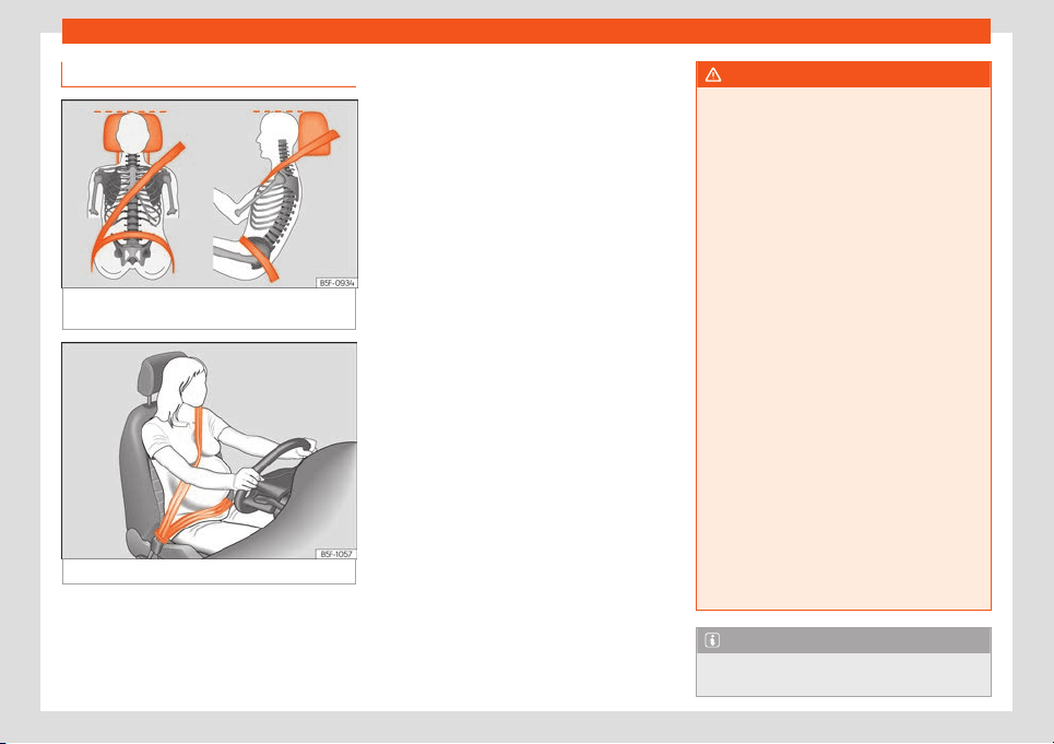
Correct seat belt position
Fig. 12
Correct seat belt and headrest posi-
tions, vie
w
ed fr
om fr
ont and the side
.
Fig. 13 Position of seat belt during pregnancy.
Seat belts offer their maximum protection in
the e
v
ent of an accident and r
educe the risk
of sust
aining se
v
er
e or fatal injuries only when
they are properly positioned. Furthermore, if
the webbing is correctly positioned, the seat
belt will hold the vehicle occupants in the op-
timum position to ensure the airbag provides
the maximum protection. The seat belt must
therefore always be worn and the webbing
correctly positioned.
Incorrectly worn seat belts can cause severe
or even fatal injuries
›››
page 12, Correct sit-
ting position of vehicle occupants.
●
The shoulder part of the seat belt must lie
on the centre of the shoulder, never across
the neck or the arm, under the arm or behind
the shoulder.
●
The lap part of the seat belt must lie across
the pelvis, never across the stomach.
●
The seat belt must lie flat and fit comforta-
bly. Pull the belt tight if necessary to take up
any slack.
In the case of pregnant women, the seat belt
must lie evenly across the chest and as low
as possible over the pelvis, never across the
stomach and must be worn properly at all
times during the pregnancy
›››
Fig. 13.
Adapting the position of the belt webbing
to your size
The seat belt can be adapted using the fol-
lowing equipment:
●
Belt height adjustment for the front seats.
●
Front seat height adjustment.
WARNING
An incorrectly worn seat belt web can
cause severe or fatal injuries in the ev
ent of
an accident.
●
The shoulder part of the seat belt must lie
on the centre of the shoulder, never across
the neck or the arm.
●
The seat belt must lie flat and fit comfort-
ably on the torso
●
The lap part of the seat belt must lie
across the pelvis, never across the stom-
ach. The seat belt must lie flat and fit com-
fortably on the pelvis Pull the belt tight if
necessary to take up any slack.
●
For pregnant women, the lap part of the
seat belt must lie as low as possible over
the pelvis and always lie flat, “surrounding”
the stomach
›››
Fig. 13.
●
Do not twist the seat belt while it is fas-
tened.
●
Once the seat belt is positioned correct-
ly, don't pull it away from your body with
your hand.
●
Do not lie the seat belt across rigid or
fragile objects, e.g. glasses, pens or keys.
●
Never use seat belt clips, retaining rings
or similar instruments to alter the position
of the belt webbing.
Note
If your physical constitution prevents you
from maintaining the correct position of the
20
Seat belts
belt webbing, contact a specialised work-
shop for help with any special devices to
ensure the optimum protection of the seat
belt and airbag. SEAT r
ecommends taking
your car in for technical service.
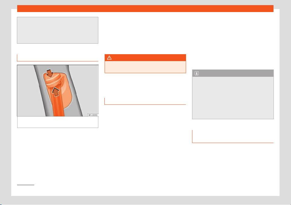
Seat belt height adjustment
Fig. 14 Next to the front seats: belt height ad-
just
er
.
Using the height adjusters for the front seats
and the out
er seats of the second r
o
w
, the
position of the seat belts can be adjust
ed in
the shoul
der ar
ea according to the height of
the occupant:
●
Keep the guide device pressed down in the
direction of the arrow
›››
Fig. 14.
●
Move the guide device up or down until the
seat belt lies over the centre of your shoulder
›››
page 19.
●
Release the guide device.
●
Pull the belt sharply to check that the de-
vice is engaged securely.
WARNING
Never adjust the belt height while the vehi-
cle is in motion.
Seat belt tensioners
Ho
w the seat belt t
ensioner w
orks
The seat belts for the front seats and the side
r
ear seats on the second r
o
w
1)
ar
e equipped
with belt t
ensioners.
The belt t
ensioners ar
e activated by sensors,
although only in severe head-on, lateral and
rear-end collisions. This retracts and tightens
the seat belts, reducing the forward motion of
the occupants.
The belt pre-tensioners work in combination
with the airbag system. In case of overturn,
the pre-tensioners do not activate unless the
head airbags are deployed.
Reversible seat belt tensioning
In specific driving situations, a reversible ten-
sioning of the seat belts might take place
›››
page 22. For example:
●
in the event of sudden brakes
●
in the event of oversteering or understeer-
ing
●
in the event of minor collisions
Note
●
If the seat belt tensioners are triggered, a
fine dust is produced. This is normal and it
is not an indication of fire in the vehicl
e.
●
The relevant safety requirements must be
observed when the vehicle or components
of the system are scrapped. Specialised
workshops are familiar with these regula-
tions, which are also available to you.
Maintenance and disposal of seat
belt t
ensioners
The belt tensioners are components of the
seat belts that ar
e inst
all
ed in the seats of
your v
ehicl
e
. If you w
ork on the belt tension-
ers or remove and install parts of the system
when performing other repair work, the seat
belt may be damaged. The consequence
»
1)
Depending on version/market.
21
Safety
may be that, in the event of an accident, the
belt t
ensioners function incorr
ectly or may
not function at all.
So that the eff
ectiv
eness of the seat belt t
en-
sioner is not r
educed and that r
emoved parts
do not cause any injuries or environmental
pollution, regulations, which are known to the
specialised workshops, must be observed.
WARNING
●
Improper use or repairs not carried out by
qualified mechanics increase the risk of se-
vere or fat
al injuries. The belt tensioners
may fail to trigger or may trigger in the
wrong circumstances.
●
The seat belt tensioner, seat belt and au-
tomatic retractor cannot be repaired.
●
Any work on the belt tensioners and seat
belts, including the removal and refitting of
system parts in conjunction with other re-
pair work, must be performed by a special-
ised workshop only.
●
The belt tensioners will only provide pro-
tection for one accident and must be
changed if they have been activated.
For the sake of the environment
Airbag modules and belt tensioners may
contain perchlorate. Observ
e the legal re-
quirements for their disposal.
PreCrash system*
Ho
w it w
orks
The PreCrash system is an assistance system
that actives a series of measures to protect
the occupants of the vehicl
es in potentially
risky situations, but which cannot prevent a
collision.
It only works completely if no special driving
profile is selected
›››
page 22 and if there
are no operating anomalies
›››
page 263,
›››
page 22.
Basic features
Depending on the legal provisions of the
country and the features of the vehicle, in crit-
ical situations (e.g. in certain cases of emer-
gency braking or loss of control of the vehicle
by the driver) the following functions can be
activated separately or at the same time
from a specific speed.
●
Reversible tensioning of front seat belts that
are fastened.
●
Depending on the features, aut
omatic clo-
sure of the glass roof and the windows to a
slit.
●
In the event of the vehicle overturning, acti-
vation of the seat belt tensioners and head-
protection airbags.
In addition, in vehicles with an emergency
brake assistance system (Front Assist)
In vehicles with Front Assist
›››
page 273,
within the limits of the system, information is
used to assess the risk of collision with the
previous vehicle. If there is a high risk of rear
collision or during the activation of Front As-
sist in this type of situations, the PreCrash
system functions can also be enabled.
Driving profile selection settings
In vehicles with driving profile selection, the
PreCrash system adapts to the selected set-
tings
›››
page 263.
Limited operation
The PreCrash system is not available or only
has limited availability in the following situa-
tions:
●
When ESC is activated, the reversible ten-
sioning of the seat belts or the control unit of
the airbag do not work correctly
›››
page 21,
›››
page 23
●
When ASR or ESC are disabled and when
driving in reverse
›››
page 302.
●
When there is a fault in the Front Assist sys-
tem
›››
page 273.
Problems and solutions
If the PreCrash is not working correctly, the
message System unavailable or System
22

Airbag system
with limited features is sho
wn perma-
nently on the dashboar
d displ
ay.
Hav
e the syst
em check
ed by a specialised
w
orkshop.
WARNING
The PreCrash system cannot overcome the
limits imposed by the laws of physics; it on-
ly works within the limits of the system.
Risks that compromise safety ar
e never jus-
tified by the use of this system. The system
is not a replacement for driver awareness
and cannot prevent a collision.
●
Adapt your speed and safe distance to
the vehicle in front of you at all times to suit
the visibility, weather, road and traffic con-
ditions.
●
The system is not always able to recog-
nise objects.
●
The system may not react to people or
animals or objects that cross length-wise
or that are hard to detect.
●
Metallic objects (e.g. fences) or other el-
ements of the public road or adverse
weather conditions can hinder its operation
and thus its ability to detect collision risk.
●
Never ignore the warning lamps that light
up or the messages shown on the dash-
board.
WARNING
Distracting the driver in any way can lead
to an accident and cause injuries.
●
Never change settings on the Infotain-
ment System whil
e driving.
Airbag system
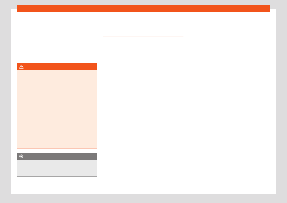
Brief intr
oduction
R
el
at
ed video
Fig. 15 Vehicle interior
Why is it so important to wear a
seat belt and t
o sit corr
ectly?
For the inflating airbags to achieve the best
pr
ot
ection, the seat belt must al
w
ays be w
orn
pr
operly and the corr
ect sitting position must
be assumed.
The airbag system is not a substitute for seat
belts, but it is an integral part of the vehicle's
overall passive safety system. Please bear in
mind that the airbag system can only work
effectively when the vehicle occupants are
wearing their seat belts correctly and have
adjusted the headrests properly. Therefore, it
is most important to properly wear the seat
belts at all times, not only because this is re-
quired by law in most countries, but also for
»
23
Safety
your safety
›
›
›
page 16, The whys and
wher
ef
or
es of seat belts
.
The airbag inflates in a matter of seconds, so
if you are not properly seated when the air-
bag is triggered, you may sustain fatal inju-
ries. Therefore, it is essential that all vehicle
occupants assume a correct sitting position
while travelling.
Sharp braking before an accident may cause
a passenger not wearing a seat belt to be
thrown forward into the area of the deploying
airbag. In this case, the inflating airbag may
inflict critical or fatal injuries on the occupant.
This also applies to children.
Always maintain the greatest possible dis-
tance between yourself and the front airbag.
This way, the front airbags can completely
deploy when triggered, providing their maxi-
mum protection.
The most important factors for triggering the
airbag are the type of accident, the angle of
impact and the vehicle speed.
Whether or not the airbags are triggered de-
pends primarily on the vehicle deceleration
rate resulting from the collision and detected
by the control unit. If the vehicle deceleration
occurring during the collision and measured
by the control unit remains below the speci-
fied reference values, the front, side and/or
head-protection airbags will not be triggered.
Take into account that the visible damage in
a vehicle involved in an accident, no matter
how serious, is not a determining factor for
the airbags to have been triggered.
WARNING
●
Wearing the seat belt incorrectly or as-
suming an incorrect sitting position can
lead to critical or fat
al injuries.
●
All vehicle occupants, including children,
who are not properly belted can sustain
critical or fatal injuries if the airbag is trig-
gered. Children up to 12 years old should
always travel on the rear seat. Never trans-
port children in the vehicle if they are not
restrained or the restraint system is not ap-
propriate for their age, size or weight.
●
To reduce the risk of injury from an inflat-
ing airbag, always wear the seat belt prop-
erly
›››
page 16.
Description of the airbag system
The airbag system offers additional protec-
tion f
or the occupants in combination with the
seat belts.
The airbag syst
em comprises the f
oll
o
w-
ing modul
es (as per v
ehicle equipment):
●
Electronic control unit
●
Front airbags for driver and passenger
●
Knee airbag for the driver
●
Side airbags
●
Head airbag
●
Airbag control lamp on the instrument
panel
›››
page 25
●
Key-operated switch for front passenger
airbag
●
Control lamp for disabled/enabled status
of the front passenger airbag.
The airbag system operation is monitored
electronically. The airbag control lamp will il-
luminate for a few seconds every time the ig-
nition is switched on (self-diagnosis).
There is a fault in the system if the control
lamp :
●
does not light up when the ignition is
switched on
›››
page 25,
●
turns off after 4 seconds after the ignition is
switched on,
●
turns off and then lights up again after the
ignition is switched on,
●
illuminates or flashes while the vehicle is
moving.
The airbag system is not triggered if:
●
the ignition is switched off
●
there is a minor frontal collision
●
there is a minor side collision
●
there is a rear-end collision
●
the vehicle turns over.
24
Airbag system
WARNING
●
The seat belts and airbags can only pro-
vide maximum protection if the occupants
are seated correctly
›
››
page 12.
●
If a fault has occurred in the airbag sys-
tem, have the system checked immediately
by a specialised workshop. Otherwise
there is a danger that during a collision, the
system may fail to trigger, or not trigger
correctly.
Airbag activation
The airbags deploy extremely rapidly, within
thousands of a second, t
o pr
o
vide additional
pr
ot
ection in the e
v
ent of an accident. A fine
dust may develop when the airbag deploys.
This is normal and it is not an indication of fire
in the vehicle.
The airbag system is only ready to function
when the ignition is on.
In special accidents instances, several air-
bags may activate at the same time.
In the event of minor head-on and side colli-
sions, rear-end collisions, overturning or roll-
over of the vehicle, airbags do not activate.
Activation factors
The conditions that lead to the airbag system
activating in each situation cannot be gener-
alised. Some factors play an important role,
such as the properties of the object the vehi-
cle hits (hard/soft), angle of impact, vehicle
speed, etc.
Deceleration trajectory is key for airbag acti-
vation.
The control unit analyses the collision trajec-
tory and activates the respective restraint
system.
If the deceleration rate is below the prede-
fined reference value in the control unit the
airbags will not be triggered, even though the
accident may cause extensive damage to the
car.
The following airbags are triggered in seri-
ous head-on collisions:
●
Driver airbag.
●
Front passenger front airbag
●
Knee airbag for the driver.
The following airbags are triggered in seri-
ous side-on collisions:
●
Front side airbag on the side of the acci-
dent.
●
Curtain (head) airbag on the side of the ac-
cident.
In an accident with airbag activation:
●
the interior lights switch on (if the interior
light switch is in the courtesy light position);
●
the hazard warning lights switch on;
●
all doors are unlocked;
●
the fuel supply to the engine is cut;
●
an emergency call is started*
›››
page 41.
Operation of the airbags
Airbag system control lamps
It lights up on the combi-instru-
ment
Fault in the airbag system and seat belt tensioners .
Have the system checked immediately by a special-
ised workshop
.
It lights up on the dash panel
Fault in the airbag system.
Have the system checked immediately by a special-
ised workshop.
Front passenger front airbag deactivated.
Check if the airbag should be kept deactivated
»
25
Safety
It lights up on the dash panel
Front passenger front airbag activated.
The control lamp turns off automatically 60 seconds
after the ignition is switched on
Several warning and control lamps light up
for a few seconds when the ignition is switch-
ed on, signalling that the function is being
verified. They will s
witch off after a few sec-
onds.
If the airbag and seat belt tensioner system
control lamp remains on or flashes, it indi-
cates a malfunction in the airbag and seat
belt tensioner system
›››
. Have the system
check
ed immediat
ely by a specialised w
ork
-
shop
.
If the fr
ont passenger airbag is deactiv
ated,
the warning lamp re-
mains lit on the dash panel to remind you that
the airbag is deactivated. If, with the front
passenger airbag deactivated, this lamp
does not remain lit or if it is lit along with the
control lamp on the instrument panel,
there is a fault in the airbag system
›››
. If
the contr
ol l
amp is fl
ashing, ther
e is a f
ault in
the disabling of the airbag syst
em
›
››
. Have
the syst
em check
ed immediat
ely by a speci-
alised w
orkshop
.
WARNING
In the event of a fault in the airbag and seat
belt tensioner system, the airbags and seat
belts may not trigger correctly, may fail to
trigger or may even trigger unexpectedly.
●
The vehicle occupants run the risk of sus-
t
aining severe or fatal injuries. Have the
system checked immediately by a special-
ised workshop.
●
Do not mount a child seat in the front
passenger seat or remove the mounted
child seat! The front passenger front airbag
may deploy during an accident in spite of
the fault.
CAUTION
Always pay attention to any lit control
lamps and to the corresponding descrip-
tions and instructions to avoid damage to
the v
ehicle or harm to the occupants.
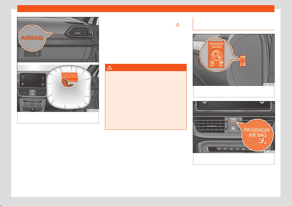
Front airbags
Fig. 16
Driver airbag located in steering
wheel
.
26
Airbag system
Fig. 17 Front passenger airbag located in dash
panel
.
The front airbag for the driver is located in the
st
eering wheel
›
›
›
Fig. 16
and the airbag f
or
the fr
ont passenger is located in the dash
panel
›››
Fig. 17. Airbags are identified by the
word “AIRBAG”.
When the driver and front passenger airbags
are deployed, the covers remain attached to
the steering wheel and dashboard, respec-
tively
›››
Fig. 16
›››
Fig. 17.
In conjunction with the seat belts, the front
airbag system gives the front occupants ad-
ditional protection for the head and chest in
the event of a severe frontal collision
›››
.
Their special design all
o
ws the contr
oll
ed es-
cape of the pr
opell
ant gas when an occu-
pant puts pr
essure on the bag. Thus, the
head and chest are protected by the airbag.
After the collision, the airbag deflates suffi-
ciently to allow visibility.
WARNING
●
The deployment space between the front
passengers and the airbags must not in
any case be occupied by other passenger,
pets and objects.
●
The airbags pro
vide protection for just
one accident; replace them once they have
deployed.
●
It is also important not to attach any ob-
jects such as cup holders or telephone
mountings to the surfaces covering the air-
bag units.
Activate and deactivate front pas-
senger fr
ont airbag*
Fig. 18
Switch for activating and deactivating
the fr
ont passenger airbag.
Fig. 19
Dash panel: control lamp for the deac-
tiv
ation of the fr
ont passenger fr
ont airbag.
Deactivate the front passenger front airbag
only if you hav
e t
o use a r
ear
-f
acing chil
d
seat in the fr
ont passenger seat.
»
27
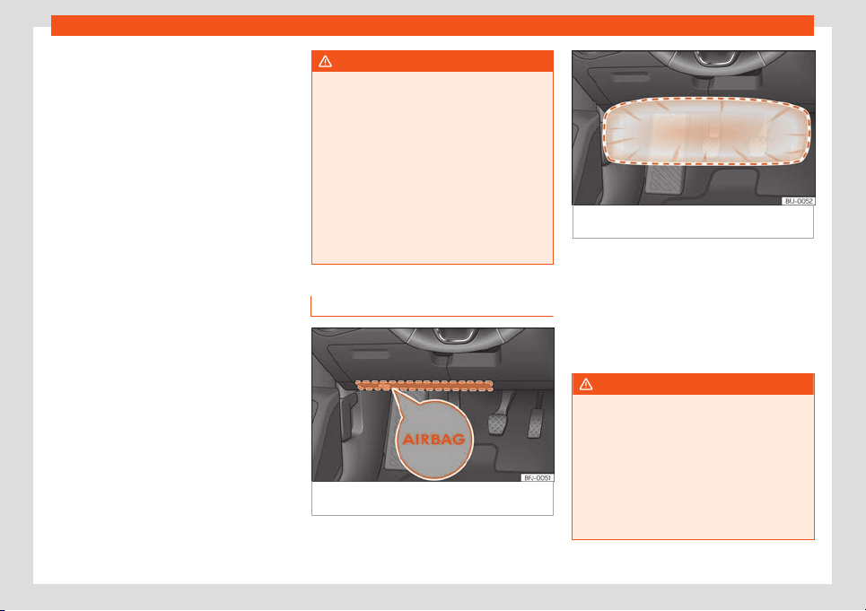
Safety
SEAT recommends fitting the child seat in the
r
ear seat t
o av
oid having t
o deactiv
at
e the
fr
ont passenger airbag.
When the front passenger airbag is deacti-
vated, this means that only the front passen-
ger front airbag is deactivated. All the other
airbags in the vehicle remain activated.
Deactivate and activate the front passen-
ger front airbag
●
Switch the ignition off.
●
Open the door on the front passenger side.
●
Insert the key into the slot of the switch for
deactivating the front passenger airbag
›››
Fig. 18. About 3/4 of the key should enter;
this is as far as it will go.
●
Turn the key gently to change its position to
(deactivate) or to (activate). If you have
difficulty, ensure that you have inserted the
key as far as it will go.
●
Close the front passenger door.
●
When deactivating the airbag, switch the
ignition on and check that the control lamp
remains lit where it says
in the central part of the
dashboard
›››
Fig. 19.
●
When reactivating the airbag, check that
when the ignition is switched on, the
control lamp does not light up and the
lamp lights up for 60 seconds and then turns
off.
WARNING
●
The driver of the vehicle is responsible for
disabling or s
witching on the airbag.
●
Always switch off the ignition before dis-
abling the front passenger airbag! Failure
to do so could result in a fault in the airbag
deactivation system.
●
Never leave the key in the airbag disa-
bling switch as it could get damaged or en-
able or disable the airbag during driving.
●
If for any reason an airbag is deactivated,
reactivate it as soon as possible so that it
can fulfil its protective function.
Knee airbag*
Fig. 20 On the driver side: location of the knee
airbag
Fig. 21 On the driver side: airbag action radius
for the knees.
The knee airbag is located on the driver side
bel
o
w the dash panel
›
›
›
Fig. 20
. Airbags ar
e
identified by the word “AIRBAG”.
The area framed in red (deployment area)
›››
Fig. 21 is covered by the knee airbag when
it is deployed. Objects should never be
placed or mounted in this area.
WARNING
●
The knee airbag is deployed in front of
the driver's knees. Always k
eep the deploy-
ment areas of the knee airbags free.
●
Never not fix objects to the cover or in the
deployment area of the knee airbag.
●
Adjust the driver's seat so that there is a
distance of at least 10 cm (4 inches) be-
tween your knees and the location of the
this airbag. If your physical constitution
28
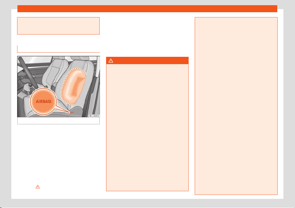
Airbag system
prevents you from meeting these require-
ments, make sure you contact a special-
ised workshop.
Side airbags*
Fig. 22 Side airbag in driver's seat.
The side airbags are located in the driver's
seat and fr
ont passenger seat backr
ests
›
›
›
Fig. 22
.
The l
ocations are identified by the text “AIR-
BAG” in the lower region of the backrests.
In conjunction with the seat belts, the side air-
bags system gives additional protection for
the head and upper body in the event of a
severe side collision and, depending on the
features, also in the event of the vehicle over-
turning
›››
.
In a side collision, the side airbags reduce the
risk of injury t
o passengers t
o the ar
eas of the
body f
acing the impact. In addition t
o their
normal pr
ot
ection, the seat belts also hold
the passengers in the event of a side collision;
this is how these airbags provide maximum
protection.
WARNING
●
If you do not wear a seat belt, if you lean
forward, or are not seat
ed correctly while
the vehicle is in motion, you are at a greater
risk of injury if the side airbag system is
triggered in an accident.
●
In order for the side airbags to provide
their maximum protection, the prescribed
sitting position must always be maintained
with seat belts fastened while travelling.
●
In a side-on collision the side airbags will
not work if the sensors do not correctly
measure the pressure increase on the inte-
rior of the doors, due to air escaping
through the areas with holes or openings in
the door panel.
●
Never drive if the interior door panels
have been removed or if the panels have
not been correctly fitted.
●
Never drive the vehicle if the loudspeak-
ers in the door panels have been removed,
unless the holes left by the loudspeakers
have been closed properly.
●
Always check that the openings are
closed or covered if loudspeakers or other
equipment are fitted inside the door pan-
els.
●
Occupants of the outer seats must never
carry any objects or pets in the deploy-
ment space betw
een them and the airbags,
or allow children or other passengers to
travel in this position. It is also important
not to attach any accessories (such as cup
holders) to the doors. This would impair the
protection offered by the side airbags.
●
The built-in coat hooks should be used
only for lightweight clothing. Do not leave
any heavy or sharp-edged objects in the
pockets.
●
Great forces, such as hard blows or kicks,
must not be exerted upon the backrest bol-
ster because the system may be damaged.
In this case, the side airbags would not be
triggered.
●
Under no circumstances should protec-
tive covers be fitted over seats with side
airbags unless the covers have been ap-
proved for use in your vehicle. Because the
airbag deploys from the side of the back-
rest, the use of conventional seat covers
would obstruct the side airbag, seriously
reducing the airbag's effectiveness.
●
Any damage to the original seat uphols-
tery or around the seams of the side airbag
units must be repaired immediately by a
specialised workshop.
●
The airbags provide protection for just
one accident; replace them once they have
deployed.
»
29
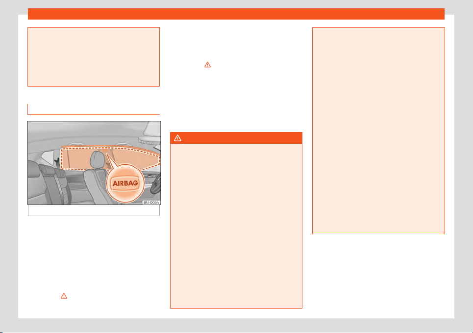
Safety
●
Any work on the side airbag system or re-
moval and install
ation of the airbag com-
ponents for other repairs (such as removal
of the front seat) should only be performed
by a specialised workshop. Otherwise,
faults may occur during the airbag system
operation.
Head-protection airbags*
Fig. 23
Location of head-protection airbags.
The head-protection airbags are located on
both sides in the int
erior abo
v
e the doors
›
›
›
Fig. 23
and are identified with the text “AIR-
BAG”.
In conjunction with the seat belts, the head-
protection airbag system gives the vehicle
occupants additional protection for the head
and upper body in the event of a severe side
collision
›››
.
The area framed in red is covered by the
head-pr
ot
ection airbag when it is depl
oyed
›
›
›
Fig. 23
(deployment area). Therefore, ob-
jects should never be placed or mounted in
this area
›››
.
In the e
v
ent of a side collision the head-pr
o-
t
ection airbag is trigger
ed on the impact side
of the v
ehicl
e.
The head-protection airbags reduce the risk
of injury to passengers in the front and rear
side seats facing the impact.
WARNING
●
In order for the head-protection airbags
to pro
vide their maximum protection, the
prescribed sitting position must always be
maintained with seat belts fastened while
travelling.
●
For safety reasons, the head-protection
airbag must be disabled in those vehicles
fitted with a screen dividing the interior of
the vehicle. See your technical service to
make this adjustment.
●
There must be no other persons, animals
or objects between the occupants of the
outer seats and the deployment space of
the head-protection airbags so that the
head-protection airbag can deploy com-
pletely without restriction and provide the
greatest possible protection. Therefore,
sun blinds which have not been expressly
approved for use in your vehicle may not be
attached to the side windows
●
The built-in coat hooks should be used
only for lightweight clothing. Do not leav
e
any heavy or sharp-edged objects in the
pockets. Please, do not hang the clothes on
coat hangers.
●
The airbags provide protection for just
one accident; replace them once they have
deployed.
●
Any work on the head-protection airbag
system or removal and installation of the
airbag components for other repairs (such
as removal of the roof lining) should only
be performed by a specialised workshop.
Otherwise, faults may occur during the air-
bag system operation.
●
The side and head airbags are managed
through sensors located in the interior of
the front doors. To ensure the correct oper-
ation of the side and head-protection air-
bags neither the doors nor the door panels
should be modified in any way (e.g. fitting
loudspeakers). If the front door is dam-
aged, the airbag system may not work cor-
rectly. All work carried out on the front door
must be done in a specialised workshop.
30
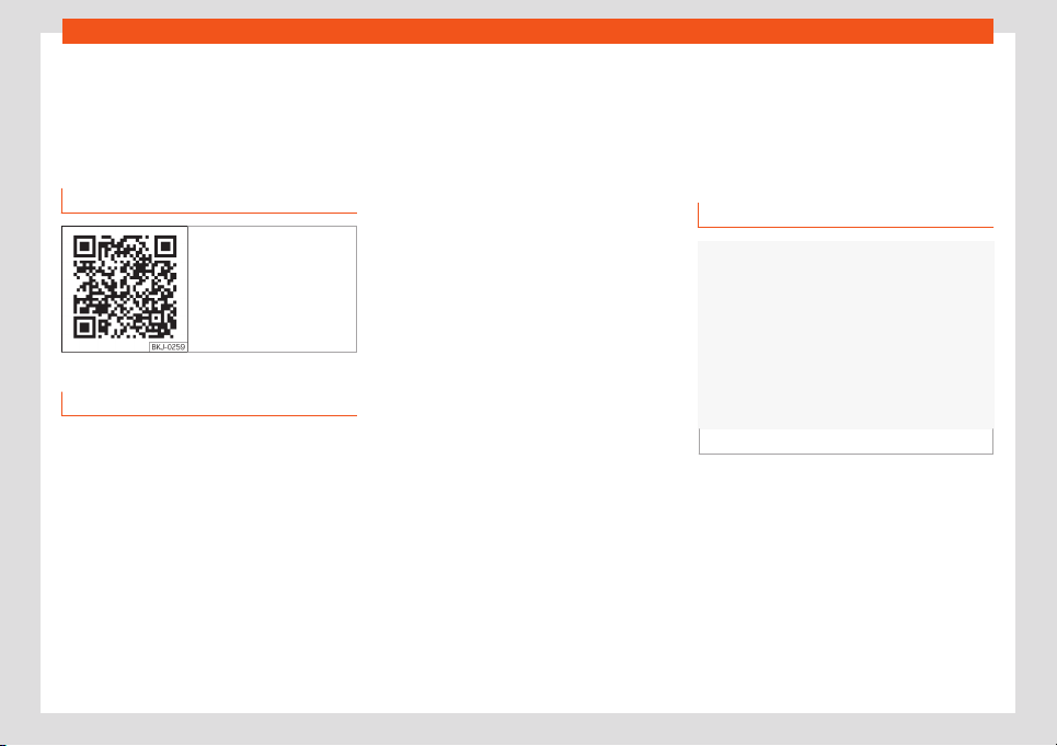
Transporting children safely
Transporting children
saf
ely
Saf
et
y f
or chil
dr
en
R
elated video
Fig. 24 Vehicle interior
Introduction
For safety reasons, as we have learned from
accident st
atistics, w
e r
ecommend that chil
-
dr
en under 12 years of age tr
av
el in the rear
seats. Depending on their age, height and
weight, children travelling in rear seats must
use a child seat or a seat belt. For safety rea-
sons, the child seat should be installed in the
rear seat, behind the front passenger seat or
in the centre back seat.
The physical laws involved and the forces
acting in a collision apply also to children
›››
page 18. But unlike adults, children do not
have fully developed muscle and bone struc-
tures. This means that children are subject to
a greater risk of injury.
To reduce the risk of injuries, children must al-
ways use special child restraint systems
when travelling in the vehicle.
We recommend the use of child safety prod-
ucts from the SEAT Original Accessories Pro-
gramme, which includes systems for all ages
made by “Peke” (not for all countries) (see
www.seat.com).
These systems have been especially de-
signed and approved, complying with the
ECE-R44. regulation.
SEAT recommends securing the child seats
shown on the website as described below:
●
Child seats in the opposite direction of trav-
el (group 0+): ISOFIX and support peg (RO-
MER BABY SAFE PLUS SHR II + ISOFIX BASE /
PEKE G0 I-SIZE + I-SIZE BASE).
●
Child seats in the direction of travel (group
1): ISOFIX and Top Tether (ROMER DUO PLUS
+ TOP TETHER / PEKE G1 TRIFIX I-SIZE).
●
Child seats directed towards the front of
the vehicle (group 2): safety belt and ISOFIX
(ROMER KIDFIX XP).
●
Child seats directed towards the front of
the vehicle (group 3): safety belt and ISOFIX
(ROMER KIDFIX XP).
Follow the manufacturer's instructions and
observe any statutory requirements when in-
stalling and using child seats. Always read
and note
›››
page 32.
We recommend you always carry the manu-
facturer's Child Seat Instruction Manual to-
gether with the on-board documentation.
Child seats group classification
Fig. 25
Examples of child seats.
Use only child seats that are officially ap-
pr
o
v
ed and suit
abl
e f
or the chil
d.
Child seats are subject to the regulation ECE-
R 44 or ECE-R 129. ECE-R stands for: Eco-
nomic Commission for Europe Regulation.
Child seats by weight group
The child seats are grouped into 5 catego-
ries:
»
31
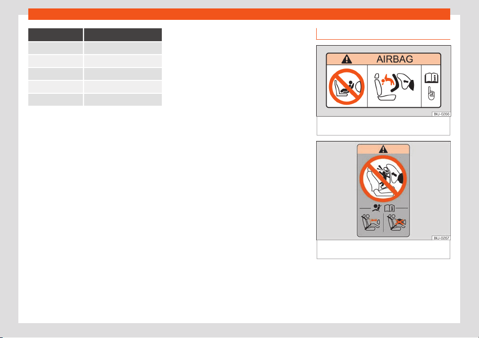
Safety
Age group Weight of the child
Group 0 Up to 10 kg
Group 0+ Up to 13 kg
Group 1 From 9 to 18 kg
Group 2 From 15 to 25 kg
Group 3 From 22 to 36 kg
Child seats that have been tested and ap-
proved under the ECE-R 44 or ECE-R 129
standard bear the test mark ECE-R 44 or
ECE-R 129 on the seat (the l
etter E in a circle
with the test number below it).
Follow the manufacturer's instructions and
observe any statutory requirements when in-
stalling and using child seats.
We recommend you to always include the
manufacturer's Child Seat Instruction Manual
together with the on-board documentation.
SEAT recommends you use child seats from
the Original Accessories Catalogue. These
child seats have been designed and tested
for use in SEAT vehicles. You can find the right
child seat for your model and age group at
SEAT dealers.
Child seats by approval category
Child seats may have the approval category
of universal, semi-universal, vehicle specific
(all according to the ECE-R 44 standard) or i-
Size (according to the ECE-R 129 standard).
●
Universal
: child seats with universal appro-
val can be installed in all vehicles. There is no
need to consult any list of models. In the case
of universal approval for ISOFIX, the child
seat is additionally provided with a Top Tether
belt.
●
Semi-universal: semi-universal approval,
in addition to the standard requirements of
universal approval, requires safety devices to
lock the child seat, which require additional
testing. Child seats with semi-universal ap-
proval include a list of vehicle models for
which they can be installed.
●
Vehicle-specific: vehicle-specific approval
requires a dynamic test of the child seat for
each vehicle model separately. Child seats
with vehicle-specific approval also include a
list of vehicle models for which they can be
installed.
●
i-Size: child seats with i-Size approval must
meet the requirements prescribed in the ECE-
R 129 standard in relation to installation and
safety. Child seat manufacturers can tell you
which seats have i-Size approval for this vehi-
cle.
Fitting and using child seats
Fig. 26 Airbag sticker: on the passenger’s sun
visor
Fig. 27 Airbag sticker: on the rear frame of the
passenger side door
Warnings about fitting a child seat
T
ak
e the f
oll
o
wing gener
al w
arnings into ac-
count if you are going to fit a child seat. They
are valid for all child seats regardless of their
attachment system.
32
Transporting children safely
●
Pl
ease r
ead and f
oll
o
w the chil
d seat man-
uf
acturer's operating instructions.
●
The child seat should preferably be fitted to
the rear seat behind the front passenger seat
so that the child can exit the vehicle on the
pavement side.
●
Set the height of the seat belt such that it
adapts to the child seat naturally, without
twisting. The lowest position of the seat belt
height regulator must be used with rear-fac-
ing child seats.
●
To correctly use a child seat in the back,
the front backrest must be adjusted so that
there is no contact with the child seat in the
back in the case that it goes opposite to the
direction of the car. In the case of front facing
restraint systems, the front backrest must be
adjusted so that there is no contact with the
child's feet.
●
If a semi-universal type chair is to be instal-
led, in which the method of attachment to the
car is through the seat belt and support
bracket, it should never be installed in the
central rear seat as the ground clearance is
lower than in other places and the support
bracket will not allow the seat to remain suffi-
ciently stable.
●
For a correct assembly of the children's
seat on the second row, adjust or dismount
the headrest, in order to prevent contact with
the chair.
●
When fitting a child seat on the front pas-
senger seat, the seat must be moved back-
wards as far as possible and placed in the
highest position. The backrest must also be
put in a vertical position
1)
.
Important information about the front pas-
senger front airbag
A sticker with important information about the
passenger airbag is located on the passeng-
er's sun visor and/or on the passenger side
door frame
›››
Fig. 26.
Read and always observe the safety informa-
tion included in the following chapters:
●
Safety distance with respect to the passen-
ger airbag
›››
page 23.
●
Objects between the passenger and the
passenger side airbag
›››
in Front airbags
on page 27.
The passenger side fr
ont airbag, when ena-
bl
ed, is a serious risk f
or a chil
d that is f
acing
backw
ar
d since the airbag can strike the seat
with such force that it can cause serious or
fatal injuries. Children up to 12 years old
should always travel on the rear seat.
Therefore we strongly recommend you to
transport children on the rear seats. This is
the safest location in the vehicle. Alternative-
ly, the front passenger airbag can be disa-
bled with a key-operated switch
›››
page 27.
When transporting children, use a child seat
suitable for the age and size of each child
›››
page 31.
WARNING
●
If a child seat is secured to the front pas-
senger seat, the risk to the child of sust
ain-
ing critical or fatal injuries in the event of an
accident increases.
●
An inflating front passenger airbag can
strike the rear-facing child seat and project
it with great force against the door, the roof
or the backrest.
●
Never install a child seat facing back-
wards on the front passenger seat unless
the front passenger front airbag has been
disabled. Risk of potentially fatal injuries to
the child! However, if necessary, the front
passenger front airbag must be deactiva-
ted
›››
page 27. If the passenger seat has a
height adjustment option, move it to the
highest, most upright position. If you have a
»
1)
Compliance with current national legislation
and the manufacturer's instructions is required
when using or inst
alling child seats.
33
Safety
fixed seat, do not install any child restraint
system in this location.
●
For those vehicles that do not include a
key l
ock switch to deactivate the airbag,
the vehicle must be taken to a technical
service. Do not forget to reconnect the air-
bag when an adult wants to sit in the front
passenger seat.
●
Never allow a child to be transported in a
vehicle without being properly secured, or
to stand up or kneel on a seat while travel-
ling. In an accident, the child could be flung
through the vehicle, causing possibly fatal
injuries to themselves and to the other vehi-
cle occupants.
●
Never leave a child alone in the child seat
or in the vehicle.
●
Children who are less than 1.5 metres tall
must not wear a normal seat belt without a
child seat, as this could cause injuries to
the abdominal and neck areas during a
sudden braking manoeuvre or in an acci-
dent.
●
When a child seat is mounted in the rear
seats, the door child-proof lock should be
activated
›››
page 100.
Attachment systems
Depending on the country, different attach-
ment syst
ems ar
e used f
or saf
ely inst
alling
chil
d seats.
Att
achment systems overview
●
ISOFIX: ISOFIX is a standardised attach-
ment system allowing quick and safe attach-
ment of child seats in the vehicle. ISOFIX at-
tachment establishes a rigid connection be-
tween the child seat and the car body.
The child seat has two rigid attachment clips,
called connectors. These connectors are fit-
ted into the ISOFIX attachment rings found
between the seat cushion and the backrest
of the vehicle's back seat (on the sides). ISO-
FIX attachment systems are used mainly in
Europe
›››
page 35. If necessary, ISOFIX at-
tachment may have to be supplemented with
a Top Tether belt or a support bracket.
●
Automatic three-point seat belt. When-
ever possible, it is preferable to attach the
child seats with the ISOFIX system rather than
attaching them with an automatic three-point
seat belt
›››
page 39.
Additional attachment:
●
Top Tether: the Top Tether belt is guided
over the back of the rear seat and attached
to an anchor point with a hook. Anchor points
are located at the back of the rear seat back-
rest on the boot side
›››
page 38. The rings
for retaining the Top Tether belt are marked
with an anchor symbol.
●
Support bracket: some child seats rest on
the floor of the vehicle with a support bracket.
The support bracket prevents the child seat
from tipping forward in the event of impact.
Child seats fitted with a support bracket
should only be used in the passenger seat
and side rear seats
›››
. For the assembly of
this t
ype of seat you shoul
d al
so consult the
list of appr
o
v
ed v
ehicles for this assembly,
available in the instructions for child restraint
systems.
Recommended systems for attaching
child seats
SEAT recommends attaching child seats as
follows:
●
Baby carriers or child seats in the oppo-
site direction of travel: ISOFIX and support
bracket or i-Size.
●
Child seats in the direction of travel: ISO-
FIX and Top Tether.
WARNING
Incorrect use of the support bracket can
cause serious or fatal injury.
●
Make sure the support brack
et is correct-
ly and safely installed.
34
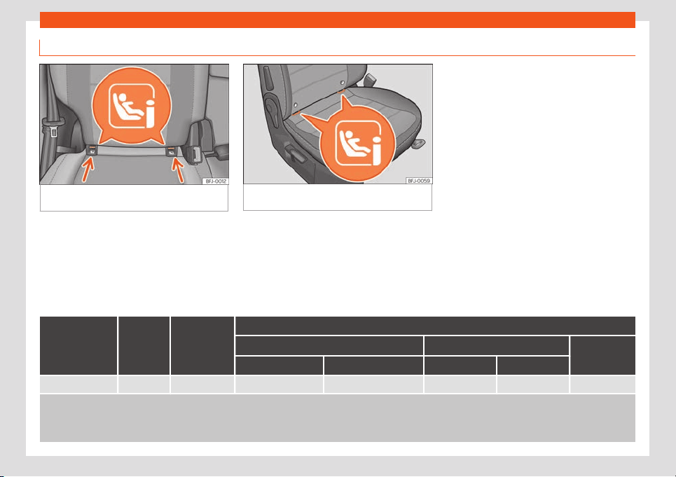
Transporting children safely
Securing the child seat with the “ISOFIX” and Top Tether system
Fig. 28 Side seats of the second row: ISOFIX/i-
Size securing rings.
Fig. 29 Front passenger seat: ISOFIX securing
rings.
Child seats can be secured quickly, easily
and saf
ely on the r
ear side seats of the sec-
ond r
o
w of seats and the fr
ont passenger
seat with the “ISOFIX” and T
op T
ether system.
Each of the side rear side seats of the second
row of seats and the front passenger seat has
two “ISOFIX” fastening rings. In some vehicles,
the rings are secured to the seat frame. The
“ISOFIX” rings are located between the back-
rest and the seat cushioning of the rear seat
›››
Fig. 28 and of the front passenger seat
›››
Fig. 29.
The Top Tether rings are located on the rear
part of the backrests of the rear seats (be-
hind the seat backrest or in the boot)
›››
Fig. 30. For the front passenger seat, the
ring is below the backrest
›››
Fig. 31.
To understand the compatibility of the "ISO-
FIX" systems in the vehicle, consult the table
below.
Weight group
Size
class
a)
Electrical
equipment
Vehicle Isofix positions
Front passenger seat Second row of seats:
Third row of
seats
b)
airbag enabled airbag disabled side centre
Group 0 to 10 kg E ISO/R1 X IL IL X X
IUF: Suitable for forward-facing ISOFIX universal child restraint systems approved for use in this weight group.
IL: It is suitable for certain ISOFIX child r
estraint systems (CRS) that can be for the specific vehicle, restricted or semi-universal categories. Take the child seat manufacturer's
vehicle list into account.
X: ISOFIX position not suitable for ISOFIX child restraint systems for this weight group or size class.
»
35

Safety
Weight group
Size
class
a)
Electrical
equipment
Vehicle Isofix positions
Front passenger seat Second row of seats:
Third row of
seats
b)
airbag enabled airbag disabled side centre
Group 0+ to 13 kg
E ISO/R1 X IL IL X X
D ISO/R2 X IL IL X X
C ISO/R3 X IL IL X X
Group I 9 to 18 kg
D ISO/R2 X IL IL X X
C ISO/R3 X IL IL X X
B ISO/F2 X IL, IUF IL, IUF X X
B1 ISO/F2X X IL, IUF IL, IUF X X
A ISO/F3 X IL, IUF IL, IUF X X
Group II 15 to 25 kg --- --- X IL IL X X
Group III 22 to 36 kg --- --- X IL IL X X
IUF: Suitable for forward-facing ISOFIX universal child restraint systems approved for use in this weight group.
IL
: It is suitable for certain ISOFIX child r
estraint systems (CRS) that can be for the specific vehicle, restricted or semi-universal categories. Take the child seat manufacturer's
vehicle list into account.
X: ISOFIX position not suitable for ISOFIX child restraint systems for this weight group or size class.
a)
The indication of class according to size corresponds to the authorised bodyweight for the child seat. In child seats with universal or semi-universal approval, the class
accor
ding t
o siz
e is indicat
ed on the ECE appr
o
v
al label. The indication of class according to size is stated on the corresponding child seat.
b)
Third row not available for all versions.
36
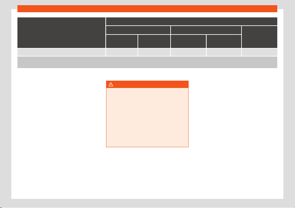
Transporting children safely
Vehicle i-Size positions
Front passenger seat Second row of seats:
Third row of
seats
a)
airbag ena-
bled
airbag disa-
bled
side centre
i-Size child seats X i-U i-U X X
i-U: Position suitable for front-facing and rear-facing child restraint systems approved under ECE R129.
X: Invalid position for child restraint syst
ems approved under ECE R129.
a)
Third row not available for all versions.
Securing the child seat with the “ISOFIX/i-
Siz
e” syst
em
Y
ou ar
e obliged t
o f
oll
ow the seat manufac-
turer's instructions.
●
Press the child seat onto the “ISOFIX” re-
taining rings
›››
Fig. 28 and
›››
Fig. 29 until the
child seat is heard to engage securely. If the
child seat is equipped with Top Tether anchor
points, secure it to the correspondent ring
›››
page 38. Observe the manufacturer's in-
structions.
●
Pull on both sides of the child seat to ensure
that it is properly anchored.
Child seats with the “ISOFIX” and Top Tether
attachment system are available from Tech-
nical Services.
WARNING
The retaining rings are designed only for
use with “ISOFIX” and Top Tether* system
child seats.
●
Never secur
e other child seats that do
not have the “ISOFIX” or Top Tether* sys-
tem, or retaining belts or objects to the fas-
tening rings - this can result in potentially
fatal injuries to the child.
●
Ensure that the child seat is secured cor-
rectly using the “ISOFIX” and Top Tether*
securing rings.
37
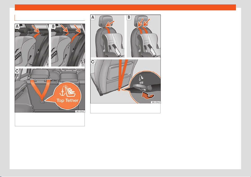
Safety
Top Tether* securing belts
Fig. 30
Side seats of the second row: adjust-
ment and assembly accor
ding t
o the T
op T
ether
belt.
Fig. 31 Front passenger seat: adjustment and
assembly accor
ding t
o the T
op T
ether belt.
Child seats with the Top Tether system come
with a str
ap f
or securing the seat t
o the v
ehi-
cl
e anchor point and pr
o
vide greater re-
straint.
The objective of this strap is to reduce for-
ward movements of the child seat in a crash,
to reduce the risk of injuries to the head from
hitting the inside of the vehicle.
Using the Top Tether in rear-facing moun-
ted seats
Currently, there are very few rear-facing child
safety seats that have Top Tether. Please
carefully read and follow the seat manufac-
turer instructions to learn the proper way to
install the Top Tether strap.
Securing the retainer strap
●
Follow the manufacturer's instructions to
deploy the child seat Top Tether retaining
strap.
●
Position the belt under the headrest
›››
Fig. 30 or ,
›››
Fig. 31 or (depending
on the instructions of the seat itself, lift or re-
move the headrest if necessary).
●
Slide the strap and secure it properly with
the anchorage of the backrest
›››
Fig. 30 ,
›››
Fig. 31 .
●
Firmly tighten the strap following the manu-
facturer's instructions.
Releasing the retaining strap
●
Loosen the strap following the manufactur-
er's instructions.
●
Push the lock and release it from the an-
choring support.
38
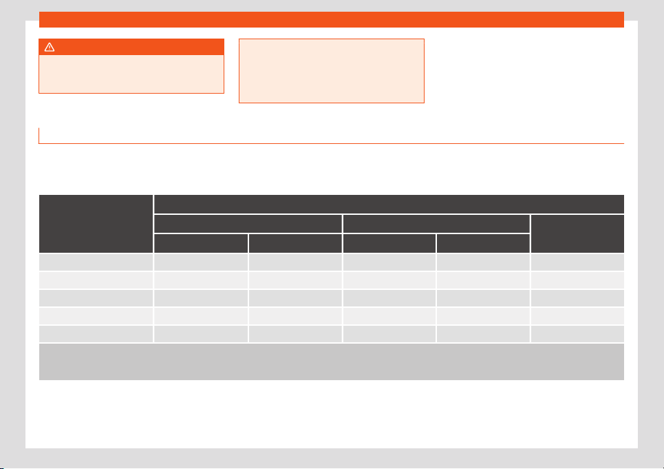
Transporting children safely
WARNING
An undue installation of the safety seat will
increase the risk of injury in the event of a
crash.
●
Never tie the retainer strap to a hook in
the luggage compar
tment.
●
Never secure or tie luggage or other
items to the lower anchorages (ISOFIX) or
the upper ones (Top Tether).
Fitting a child seat using the seat belt
If you want to fit a universal approval catego-
ry (U) child seat in your vehicle, you must
check that the seat is approv
ed for your vehi-
cle. You will find any necessary information
on the child seat’s orange ECE approval la-
bel. The following table shows the different
fitting options.
Weight group
Seat positions
Front passenger seat
a)
Second row of seats:
Third row of seats
b)
airbag enabled airbag disabled
c)
side centre
d)
Group 0 to 10 kg X U U U X
Group 0+ to 13 kg X U U U X
Group I 9 to 18 kg X U U U X
Group II 15 to 25 kg X UF UF UF X
Group III 22 to 36 kg X UF UF UF X
X: Not compatible for the installation of seats install chairs in this configuration.
U: Suit
able for universal restraint syst
ems for use in this weight group.
UF: Acceptable for front-facing universal-category child restraint systems approved for this mass group.
a)
Compliance with current national legislation and the manufacturer's instructions is required when using or installing child seats.
b)
Third row not available for all versions.
c)
Seats without height adjustment shoul
d be pl
aced in their r
earmost position. Seats
with
height adjustment shoul
d be pl
aced in their rearmost and highest position.
d)
For semi-universal chairs where the securing system is the car safety belt and the support bracket, do not use them in the centre rear seat or the third row.
»
39

Safety
Fitting a child seat using the seat belt
●
Set the height of the seat belt such that it
adapts t
o the chil
d seat nat
ur
ally, without
twisting. The l
o
w
est position of the seat belt
height regulator must be used with rear-fac-
ing child seats.
●
Put the seat belt in place and pass it
through the child seat according to the in-
structions of the child seat manufacturer.
●
Make sure that the seat belt is not twisted.
●
Insert the latch plate into the seat's buckle
until you hear the engagement click.
WARNING
When travelling, children must be secured
in the vehicle with a restraint system suita-
bl
e for age, weight and size.
●
Read and always observe information
and warnings concerning the use of child
seats
›››
page 32.
40
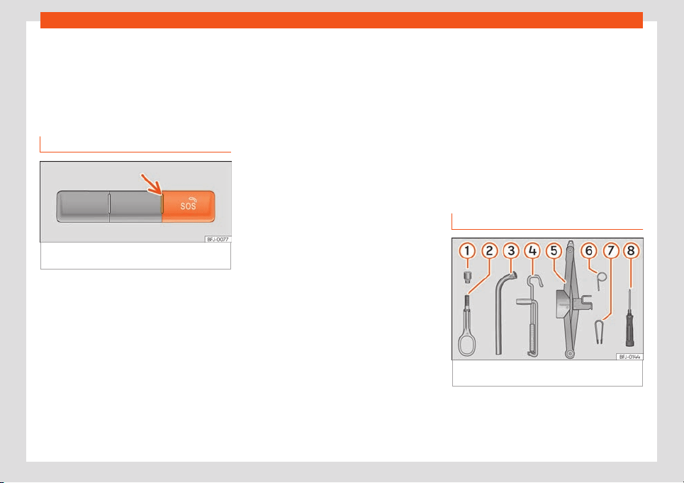
Self-help
Emergencies
Self
-help
Emer
gency call service*
Ho
w it w
orks
Fig. 32
On the roof console: control for the
emer
gency call service
Press the
›
›
›
Fig. 32
butt
on on the t
op cen-
tr
e console to start the “Emergency call”
service.
A built-in control unit establishes the connec-
tion. When a voice service is activated, a con-
nection is established with a phone line.
Control lamp
The control has a warning lamp
›››
Fig. 32
(arrow). It shows the following statuses:
●
Off: The voice service is disabled.
●
It lights up red: System malfunction. The
voice service is available with some restric-
tions. SEAT suggests going to a specialised
workshop.
●
It lights up green: The voice service is avail-
able. The system works correctly.
●
Flashes green: There is an ongoing voice
connection.
Emergency call service
●
If an emergency call is conducted manual-
ly or activated automatically in the event of
an accident with an airbag triggering, infor-
mation relevant to the emergency is broad-
cast, e.g. the current location of the vehicle
›››
page 384.
●
The person on the phone will always speak
the local language of the country.
Emergency number 112
The call is made directly to the 112 emergen-
cy number of the country.
The following conditions may cause limited
functionality of the emergency call service:
●
The emergency call is made from an area
with weak or no mobile and GPS signal, as
well as e.g. tunnels, between very tall build-
ings, garages, underground walkways, moun-
tains and valleys.
●
In areas with sufficient mobile and GPS sig-
nal, the mobile phone network of the opera-
tor may not be available; in this case, the sys-
tem will connect to a network with a good
enough signal to make the emergency phone
call.
●
In some countries, the emergency phone
call service may not be available.
●
The components of the vehicle required for
the emergency phone call are damaged or
do not get enough power.
Emergency equipment
Vehicle tool kit
Fig. 33
Underneath the floor panel of the lug-
gage compartment: v
ehicl
e t
ool kit.
The vehicle tool kit is located under the floor
panel in the luggage compartment. T
o ac-
cess the v
ehicl
e t
ool
s
›
›
›
page 135.
The tool kit includes:
»
41
Emergencies
Adapter for the anti-theft bolt*
T
o
wing eye
, r
emo
v
abl
e
Wheel spanner*
Crank handle for jack
Jack*
Hook for extracting the central wheel
trims*
Clip for removing the wheel bolt caps
Screwdriver with hexagon socket in the
handle for screwing and unscrewing the
wheel nuts
Some of the items listed are only provided in
certain model versions, or are optional extras.
WARNING
When the vehicle tool kit, tyre mobility set
and spare wheel are loose in the interior
they can be violently thro
wn in case of a
sudden manoeuvre or braking and espe-
cially in accidents, causing serious injury.
●
Ensure that the vehicle tool kit, the tyre
mobility set and the spare wheel or tempo-
rary spare wheel are safely secured in the
luggage compartment.
WARNING
Unsuitable or damaged vehicle tools can
cause injury or accidents.
●
Never work with inappropriate or dam-
aged tools.
1
2
3
4
5
6
7
8
Note
The jack does not generally require any
maintenance. If required, it should be
greased using univ
ersal type grease.
Tyre repairs
TMS (Tyre Mobility System)*
The Anti-puncture kit* (Tyre Mobility System)
will reliably seal punctures caused by the
penetration of a foreign body of up t
o about
4 mm in diameter. Do not remove foreign
objects, e.g. screws or nails, from the tyre.
After inserting the sealant residue in the tyre,
you must again check the tyre pressure
about 10 minutes after starting the engine.
You should only use the tyre mobility set if the
vehicle is parked in a safe place, you are fa-
miliar with the procedure and you have the
necessary tyre mobility set! Otherwise, you
should seek professional assistance.
Do not use the tyre sealant in the following
cases:
●
If the wheel rim has been damaged.
●
In outside temperatures below -20°C
(-4°F).
●
In the event of cuts or perforations in the
tyre greater than 4 mm.
●
If you have been driving with very l
ow pres-
sure or a completely flat tyre.
●
If the sealant bottle has passed its use by
date.
WARNING
Using the tyre mobility system can be dan-
gerous, especially when filling the tyre at
the roadside. Please observ
e the following
rules to minimise the risk of injury:
●
Stop the vehicle safely as soon as possi-
ble. Park it at a safe distance from sur-
rounding traffic to fill the tyre.
●
Ensure the ground on which you park is
flat and solid.
●
All passengers and particularly children
must keep a safe distance from the work
area.
●
Turn on the hazard warning lights to warn
other road users.
●
Use the tyre mobility system only if you
are familiar with the necessary procedures.
Otherwise, you should seek professional
assistance.
●
The tyre mobility set is intended for tem-
porary emergency use only until you can
reach the nearest specialised workshop.
●
Replace the repaired tyre with the tyre
mobility set as soon as possible.
●
The sealant is a health hazard and must
be cleaned immediately if it comes into
contact with the skin.
42
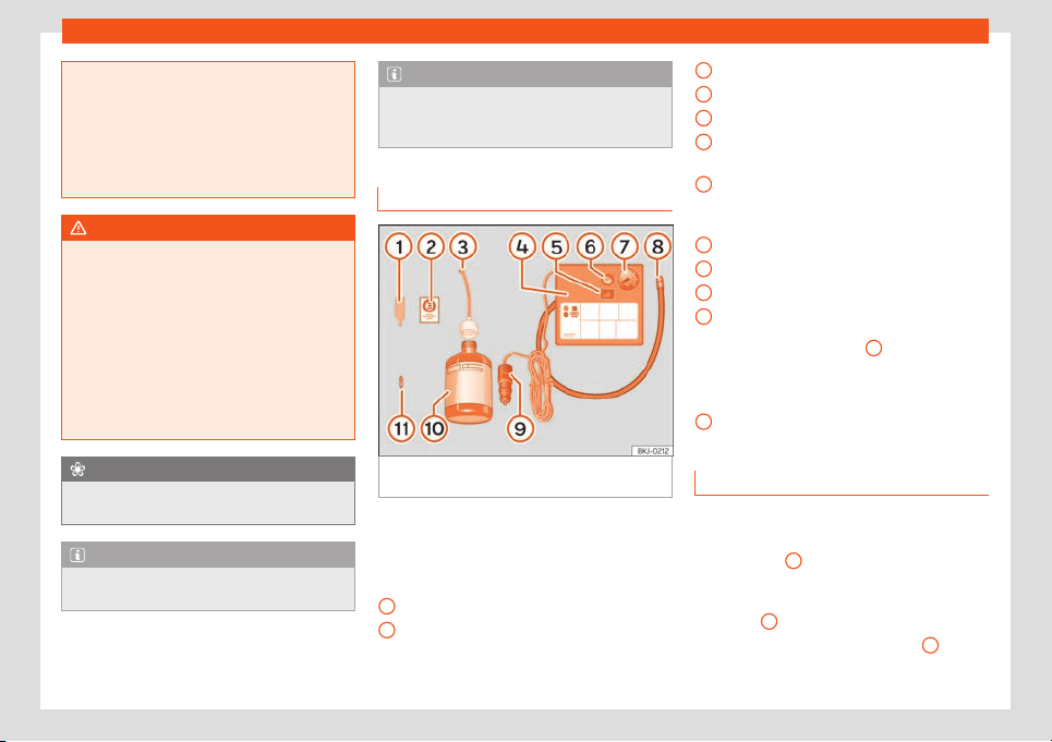
Self-help
●
Always keep the tyre mobility set out of
the r
each of small children.
●
Always stop the engine, apply the elec-
tronic parking brake and put it in gear when
using a manual gearbox, in order to reduce
the risk of involuntary movement of the ve-
hicle .
WARNING
A tyre filled with sealant does not have the
same perf
ormance properties as a conven-
tional tyre
.
●
Never drive faster than 80 km/h
(50 mph).
●
Avoid heavy acceleration, hard braking
and fast cornering.
●
Drive for only 10 minutes at a maximum
speed of 80 km/h (50 mph) and then check
the tyre.
For the sake of the environment
Dispose of used or expired sealant observ-
ing any legal requirements.
Note
A new bottle of sealant can be purchased
at SEAT dealerships.
Note
Take into account the separate instruction
manual of the tyre mobility set* manufac-
turer
.
Anti-puncture kit contents*
Fig. 34
Standard representation: anti-punc-
t
ur
e kit cont
ents.
The anti-puncture kit is located underneath
the fl
oor co
v
ering in the luggage compart
-
ment. It includes the f
oll
o
wing components
›››
Fig. 34:
Valve insert remover
A sticker to be adhered to the instrument
cluster, within the driver's visual field, to
remind that the maximum advisable
speed “max. 80 km/h” or “max. 50 mph”
1
2
Filler tube with cap
Air compr
essor
ON/OFF s
wit
ch
Air bl
eed scr
e
w (it can al
so be integrated
in the inflator tube).
Warning provided by tyre pressure moni-
toring system (it can also be integrated in
the inflator tube).
Tube for inflating tyres
12 volt connector
Bottle of sealant
Spare tyre valve
The valve insert remover
1
has a gap at
the l
o
w
er end f
or a v
al
v
e insert. The valve in-
sert can only be screwed or unscrewed in this
way. This also applies to its replacement part
11
.
Sealing and inflating a tyre
Sealing the tyre
●
Unscrew the tyre valve cap and insert. Use
the
›
›
›
Fig. 34
1
tool to remove the insert.
Pl
ace it on a cl
ean surf
ace
.
●
Shak
e the t
yr
e sealant bottle vigorously
›››
Fig. 34
10
.
●
Screw the inflator tube
›
›
›
Fig. 34
3
into
the seal
ant bottl
e
. The bottl
e's seal will br
eak
aut
omatically.
»
3
4
5
6
7
8
9
10
11
43
Emergencies
●
R
emo
v
e the lid fr
om the filling t
ube
›
›
›
Fig. 34
3
and screw the open end of the
t
ube int
o the t
yr
e v
al
v
e.
●
With the bottle upside down, empty all of
the contents into the tyre.
●
Remove the bottle from the valve.
●
Place the insert back into the tyre valve us-
ing the tool
›››
Fig. 34
1
.
Infl
ating the t
yr
e
●
Scr
e
w the compr
essor t
yre inflator tube
›››
Fig. 34
8
into the tyre valve.
●
Check that the air bleed screw is closed
›
›
›
Fig. 34
6
.
●
Start the engine and leave it running.
●
Insert the connector
›
›
›
Fig. 34
9
into the
v
ehicl
e's 12-v
olt sock
et
›
›
›
page 150.
●
Turn the air compressor on with the
ON/OFF switch
›››
Fig. 34
5
.
●
Keep the air compressor running until it rea-
ches 2.
0 t
o 2.5 bar (29-36 psi/200-250 kP
a).
A maximum of 8 minut
es
.
●
Disconnect the air compr
essor
.
●
If it does not reach the pressure indicated,
unscrew the tyre inflator tube from the valve.
●
Move the vehicle 10m so that the sealant is
distributed throughout the tyre.
●
Screw the compressor tyre inflator into the
valve.
●
Repeat the inflation process.
●
If the indicated pressure still cannot be
reached, the tyre is too badly damaged. Stop
and request assistance from an authorised
technician.
●
Disconnect the air compressor. Unscrew
the tyre inflator tube from the tyre valve.
●
When the tyre pressure is between 2.5 and
2.0 bars, continue driving without exceeding
80 km/h (50 mph).
●
Attach the sticker
›››
Fig. 34
2
to the in-
strument clust
er
, within the driv
er
's visual
fiel
d.
●
Check the pr
essur
e again after 10 minutes
›››
page 44.
WARNING
When inflating the wheel, the air compres-
sor and the inflator tube may become hot.
●
Protect hands and skin from hot par
ts.
●
Do not place the hot flexible inflator tube
or hot air compressor on flammable mate-
rial.
●
Allow them to cool before storing the de-
vice.
●
If it is not possible to inflate the tyre to at
least 2.0 bars (29 psi / 200 kPa), the tyre is
too badly damaged. The sealant is not in a
good condition to seal the tyre. Do not con-
tinue driving. Seek specialist assistance.
CAUTION
Switch off the air compressor after a maxi-
mum of 8 operational minutes to avoid
overheating! Bef
ore switching on the air
compressor again, let it cool for several mi-
nutes.
Check after 10 minutes of driving
Screw the inflator tube
›››
Fig. 34
5
again
and check the pressure on the gauge
6
.
1.3 bar (19 psi / 130 kP
a) and l
o
w
er:
●
St
op the v
ehicl
e! The tyre cannot be
sealed sufficiently with the tyre mobility set.
●
You should obtain professional assistance
›››
.
1.4 bar (20 psi / 140 kP
a) and higher:
●
Set the t
yr
e pr
essur
e t
o the corr
ect value
again.
●
Carefully resume your journey until you
reach the nearest specialised workshop with-
out exceeding 80 km/h (50 mph).
●
Have the damaged tyre replaced.
WARNING
Driving with an unsealed tyre is dangerous
and can cause accidents and serious in-
jury.
44
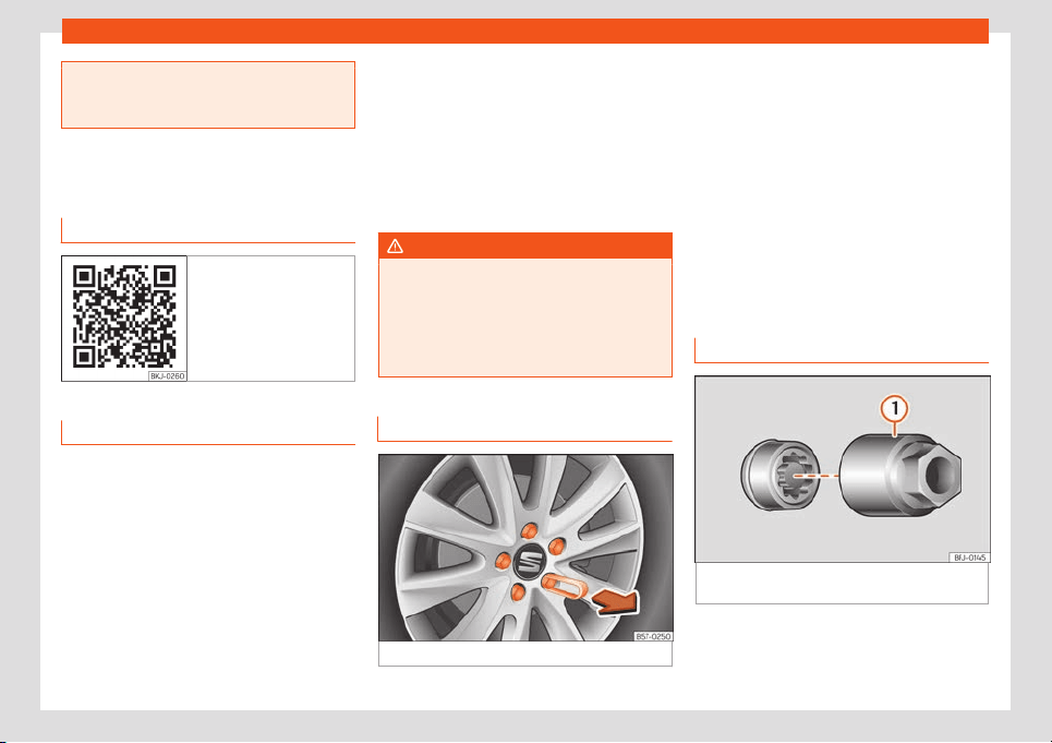
Self-help
●
Do not continue driving if the tyre pres-
sure is 1.3 bar (19 psi / 130 kPa) and lo
wer.
●
Seek specialist assistance.
Changing a wheel
Related video
Fig. 35 Wheels
What to do first
●
Park the vehicle on a horizontal surface and
in a saf
e pl
ace as f
ar aw
ay fr
om tr
affic as
possibl
e.
●
Apply the electronic parking brake.
●
Switch on the hazard warning lights.
●
Manual transmission: select the 1st gear.
●
Automatic transmission: Move the selector
lever to position P.
●
If you are towing a trailer, unhitch it from
your vehicle.
●
Have the vehicle tool kit
›››
page 41 and the
spare wheel* ready
›››
page 371.
●
Observe the applicable legislation for each
country (reflective vest, warning triangles,
etc.).
●
All occupants should leave the vehicle and
wait in a safe place (for instance behind the
roadside crash barrier).
WARNING
●
Always observe the above steps and pr
o-
tect yourself and other road users.
●
If you change the wheel on a slope, block
the wheel on the opposite side of the car
with a stone or similar to prevent the vehi-
cle from moving.
Wheel bolt caps*
Fig. 36 Wheel: wheel nuts with caps.
Removal
●
Fit the plastic clip (vehicle tools
›
›
›
Fig. 33
)
o
v
er the cap until it clicks int
o place
›››
Fig. 36.
●
Remove the cap with the plastic clip.
The caps protect the wheel nuts and should
be remounted after changing the tyre.
The anti-theft wheel locking bolt has a
special cap. This only fits on anti-theft locking
bolts and is not for use with standard wheel
nuts.
Anti-theft wheel nuts
Fig. 37
Anti-theft wheel bolt with cap and
adapt
er
.
Loosening the anti-theft wheel bolt
●
Remove the wheel cover* or the cap*.
»
45
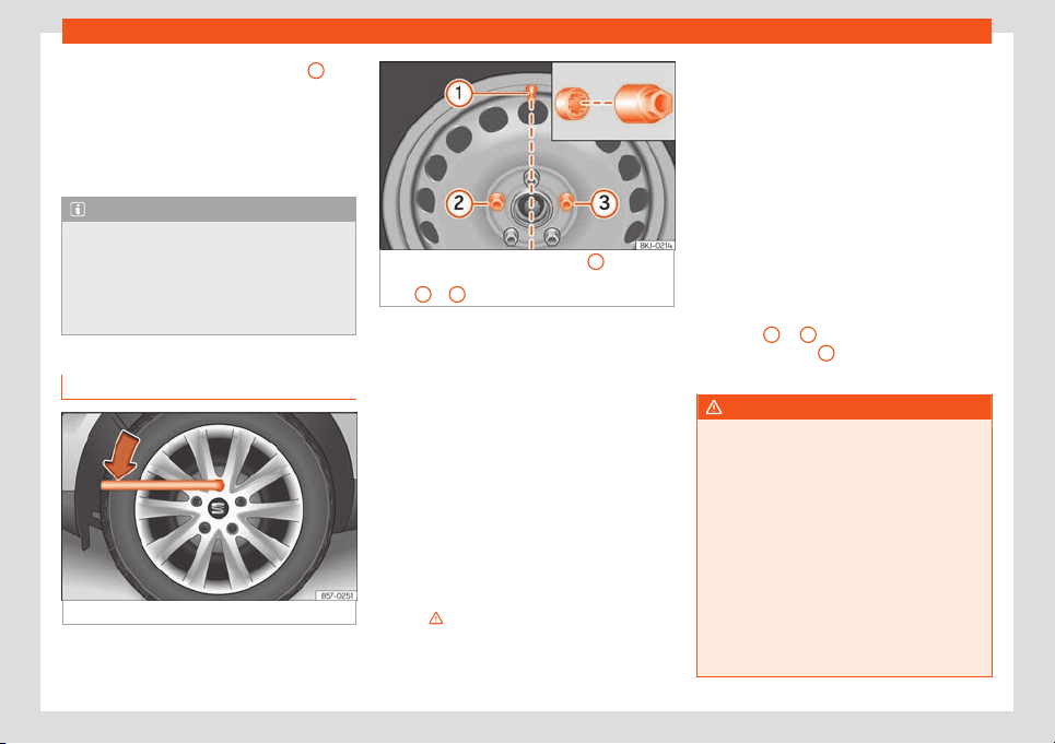
Emergencies
●
Insert the special adapt
er
›
›
›
Fig. 37
1
(ve-
hicl
e t
ool
s
›
›
›
page 41
) onto the anti-theft
wheel bolt and push it on as far as it will go.
●
Insert the wheel brace (vehicle tools) onto
the adapter as far as it will go.
●
Remove the wheel bolt
›››
page 46.
Note
Make a note of the code number of the an-
ti-theft wheel bolt and keep it in a safe
place, but not in your vehicle
. If you need a
new adapter, you can obtain it from the
SEAT Official Service, indicating the code
number.
Loosening wheel nuts
Fig. 38 Wheel change: loosen the wheel nuts.
Fig. 39 Wheel change: tyre valve
1
and the
correct position for the anti-theft wheel locking
bolt
2
or
3
.
Use only the wheel wrench belonging to the
car t
o l
oosen the wheel nuts.
L
oosen the wheel nuts only about one t
urn
bef
or
e r
aising the vehicle with the jack.
If the wheel bolt is very tight, carefully push
on the end of the wheel wrench with your
foot. Hold on to the vehicle for support and
take care not to slip during this operation.
Loosening wheel nuts
●
Fit the wheel wrench on as far as it will go
›››
Fig. 38.
●
Hold the wrench at the end and rotate the
bolt approximately one turn anticlock-
wise
›››
.
Important information about wheel nuts
F
act
ory-fitt
ed rims and wheel nuts ar
e spe-
cially mat
ched during construction. Ther
e-
f
ore, if different rims are fitted, the correct
wheel nuts with the right length and heads
must be used. This ensures that wheels are
fitted securely and that the brake system
functions correctly.
In certain circumstances, you should not even
use wheel nuts from vehicles of the same
model.
In wheels with full hubcaps, the anti-theft
locking bolt must be threaded onto positions
›››
Fig. 39
2
or
3
, taking the tyre valve’s po-
sition as r
ef
er
ence
1
. Otherwise it will not be
possibl
e t
o mount the hubcap
.
WARNING
If the wheel nuts are not properly tight-
ened, they could come loose while driving
and cause an accident, serious injury and
loss of vehicle contr
ol.
●
Use only wheel nuts which correspond to
the rim in question.
●
Never use different wheel nuts.
●
Wheel nuts and threads should be clean,
free of oil and grease, and it should be pos-
sible to screw them easily.
●
To loosen and tighten wheel nuts, only
use the wheel wrench that came with the
car from the factory.
46
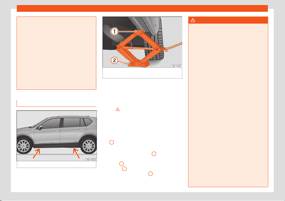
Self-help
●
The wheel nuts should only be loosened
slightly (about one turn) before raising the
v
ehicle with the jack. Risk of accident!
●
Never apply grease or oil to wheel nuts or
to the wheel hub threads. Even if the bolts
have been tightened to the prescribed tor-
que, they could come loose while driving.
●
Never loosen the screwed joints of wheel
rims with bolted ring trims.
●
If wheel nuts are tightened below the
prescribed torque, the bolts and rims could
come loose while driving. If tightening tor-
que is too high, the wheel nuts or threads
can be damaged.
Raise the vehicle
Fig. 40
Jack position points.
Fig. 41 Cross member: positioning the jack on
the vehicle.
●
Place the jack* (vehicle tools) on firm
gr
ound. If necessary use a l
ar
ge
, str
ong
boar
d or simil
ar support. If the surface is slip-
pery (for example tiles) place the jack on a
rubber mat or similar to prevent it from slip-
ping
›››
.
●
Find the support point on the strut (sunken
ar
ea) cl
osest t
o the wheel t
o be changed
›
›
›
Fig. 40.
●
Turn the jack* crank handle, located below
the strut support point, to raise it until the
tab
1
›
›
›
Fig. 41
is bel
o
w the housing pr
ovi-
ded.
●
Align the jack* so that tab
1
“grips” onto
the housing pr
o
vided on the strut and the mo-
bil
e base
2
is resting on the ground. The
base pl
at
e
2
should fall vertically with re-
spect t
o the support point
1
.
●
Continue turning the jack* until the wheel is
slightly lift
ed off the gr
ound.
WARNING
The factory-supplied jack* is only de-
signed for changing wheels on this model.
On no account attempt to use it for lifting
heavier vehicl
es or other loads. Risk of in-
jury.
●
Make sure that the jack* remains stable.
If the surface is slippery or soft, the jack*
could slip or sink, respectively, with the re-
sultant risk of injury.
●
Only raise the vehicle with the jack* sup-
plied by the manufacturer. Other jacks,
even those approved for other SEAT mod-
els could slip, with the consequent risk of
injury.
●
Only mount the jack* on the support
points designed for this purpose on the
strut, and always align the jack correctly. If
you do not, the jack* could slip as it does
not have an adequate grip on the vehicle:
risk of injury!
●
You should never place a body limb such
as an arm or leg under a raised vehicle that
is solely supported by the jack.
●
If you have to work underneath the vehi-
cle, you must use suitable stands addition-
ally to support the vehicle, there is a risk of
accident!.
●
Never raise the vehicle if it is tilting to one
side or the engine is running.
●
Never start the engine when the vehicle is
raised. The vehicle may come loose from
the jack due to the engine vibrations.
»
47
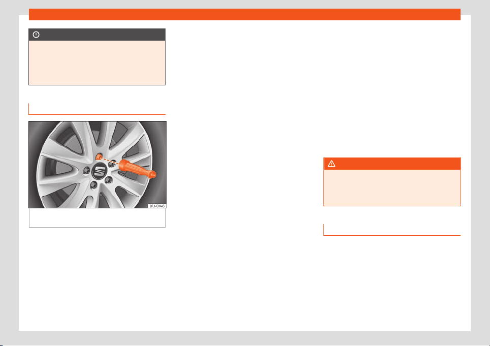
Emergencies
CAUTION
The vehicle must not be raised on the
crossbar. Only place the jack* on the
points designed for this purpose on the
strut. Otherwise, the vehicl
e may be dam-
aged.
Removing and installing a wheel
Fig. 42
Wheel change: loosen wheel nuts with
the sock
et in the handl
e of the scr
e
w
driv
er
.
Change the wheel after loosening the wheel
nuts and r
aising the v
ehicl
e with the jack
.
When r
emo
ving/fitting the wheel, the rim may
hit and damage the br
ake disc. For this rea-
son, please take care and get a second per-
son to assist you.
Taking off the wheel
●
Using the hexagonal socket in the wheel
brace
›››
Fig. 42, unscrew the slackened
wheel nuts and place them on a clean sur-
face.
●
Unscrew the wheel nuts using the box
spanner and place them on a clean surface.
●
Take off the wheel.
Putting on the spare wheel
Check the direction of rotation of the tyre
›››
page 48.
●
Place the spare wheel or temporary spare
wheel into position.
●
Replace the wheel nuts and tighten slightly
using the hexagonal socket on the end of the
wheel brace.
●
To tighten the anti-theft locking wheel nuts
use the corresponding adaptor.
●
Carefully lower the vehicle using the jack*.
●
Use the wheel spanner to tighten all of the
wheel nuts clockwise. Tighten the bolts in di-
agonal pairs (not in a circle).
●
Fit the wheel caps
›››
page 45.
The wheel nuts should be clean and turn
easily. Before fitting the spare wheel, inspect
the wheel condition and hub mounting surfa-
ces. These surfaces must be clean before fit-
ting the wheel.
Tightening torque of the wheel nuts
The recommended tightening torque for
wheel nuts for steel and alloy wheels is
140 Nm. After changing a wheel, have the
tightening torque checked immediately with a
torque wrench that is working perfectly.
Before checking tightening torque, have any
rusty wheel nuts that are difficult to screw re-
placed and clean the wheel hub threads.
Never apply grease or oil to wheel nuts or to
the wheel hub threads. Even if the bolts have
been tightened to the prescribed torque, they
could come loose while driving.
WARNING
The hexagonal socket in the wheel brace
should be used for turning wheel nuts only.
Do not use it to loosen or tighten the wheel
nuts.
Tyres with directional tread pattern
Tyres with directional tread pattern have
been designed t
o oper
at
e best when r
ot
ating
in only one dir
ection. An arr
ow on the tyre
sidewall indicates the direction of rotation on
tyres with directional tread. Always observe
the indicated direction of rotation in order to
guarantee optimum grip and help avoid
aquaplaning, excessive noise and wear.
48
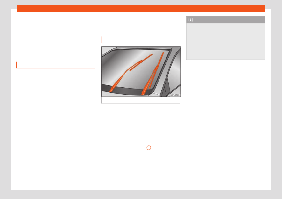
Self-help
If the tyre is mounted in the opposite direction
of r
ot
ation, driv
e with e
xtr
eme caution, as the
t
yr
e is no longer being used correctly. This is
of particular importance when the road sur-
face is wet. Change the tyre as soon as pos-
sible or remount it with the correct direction
of rotation.
Works after changing a wheel
●
Alloy wheels: replace the wheel bolt caps.
●
Plate wheels: r
eplace the wheel hubcap .
●
Return all tools t
o their proper storing loca-
tion.
●
If the replaced wheel does not fit in the
spare wheel housing, store it safely in the lug-
gage compartment
›››
page 134.
●
Check the tyre pressure of the newly moun-
ted tyre as soon as possible.
●
In vehicles fitted with a tyre pressure indica-
tor, adjust the pressure and store it in memory
›››
page 369.
●
Have the tightening torque of the wheel
nuts checked as soon as possible with a tor-
que wrench
›››
page 48. Meanwhile, drive
carefully.
●
Have the flat tyre replaced as quickly as
possible.
Changing the windscreen
wiper blades
Wiper service position
Fig. 43
Wipers in service position.
Ensure that the wiper blades are not frozen.
The wiper arms can be r
aised when the wip-
ers ar
e in service position
›
›
›
Fig. 43
.
●
Cl
ose the bonnet
›››
page 349.
●
Switch the ignition on and off.
●
Press the windscreen wiper lever down-
wards briefly
›››
page 118
4
.
Bef
or
e driving, al
w
ays l
o
w
er the wiper arms.
Using the windscreen wiper lever, the wind-
screen wiper arms return to their initial posi-
tion.
Note
●
The windscreen wiper arms can be
moved to the service position only when
the bonnet is properly closed.
●
Y
ou can also use the service position, for
example, if you want to fix a cover over the
windscreen in the winter to keep it clear of
ice.
49
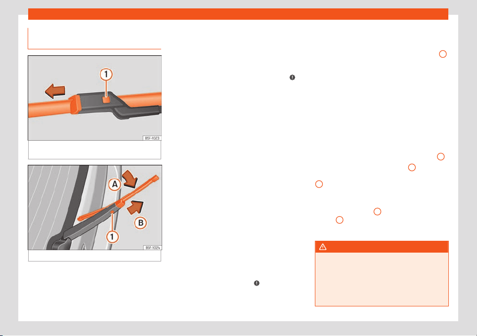
Emergencies
Changing the wiper rear wiper
bl
ades
Fig. 44
Changing the windscreen wiper
bl
ades
Fig. 45
Changing the rear wiper blade
The windscreen wiper blades are supplied as
st
andar
d with a l
ayer of gr
aphit
e
. This l
ayer is
responsible for ensuring that the wipe is silent.
If the graphite layer is damaged, the noise of
the water as it is wiped across the windscreen
will be louder.
Check the condition of the wiper blades reg-
ularly. If the wipers scrape across the
glass, they should be changed if they are
damaged, or cleaned if they are dirty
›››
.
If this does not pr
oduce the desir
ed r
esults,
the setting angl
e of the windscr
een wiper
arms might be incorr
ect. They shoul
d be
checked by a specialised workshop and cor-
rected if necessary.
Damaged windscreen wiper blades should
be replaced immediately. These are availa-
ble from qualified workshops.
Raising and lowering windscreen wiper
arms
●
Place the windscreen wipers in the service
position
›››
page 49.
●
Grip the wiper arms only by the blade's
fastening point.
Cleaning windscreen wiper blades
●
Raise the wiper arms.
●
Use a soft cloth to remove dust and dirt
from the windscreen wiper blades.
●
If the blades are very dirty, a sponge or
damp cloth may be used
›››
.
Changing the windscreen wiper blades
●
Lift and unfold the wiper arms.
●
Press and hold release button
›
›
›
Fig. 44
1
and pull gently on the wiper blade in the di-
r
ection of the arr
o
w
.
●
Fit a ne
w wiper bl
ade of the
same length
and design on to the wiper arm and hook it
into place.
●
Rest the wiper arms back onto the wind-
screen.
Changing the rear wiper blade
●
Lift and fold the wiper arm.
●
Turn the blade slightly
›››
Fig. 45 (arrow
A
).
●
Hold down the release button
1
while gen-
tly pulling the bl
ade in the dir
ection of arr
o
w
B
.
●
Insert a new blade of the same l
ength and
t
ype
in the r
ear wiper arm in the opposit
e di-
r
ection t
o the arrow
B
and hook into place
butt
on
1
.
●
Replace the wiper arm on the rear window.
WARNING
Worn or dirty windscreen wiper blades re-
duce visibility and increase the risk of acci-
dent and serious injury.
●
Always replace damaged or w
orn wind-
screen wiper blades or blades that no lon-
ger clean the windscreen properly.
50
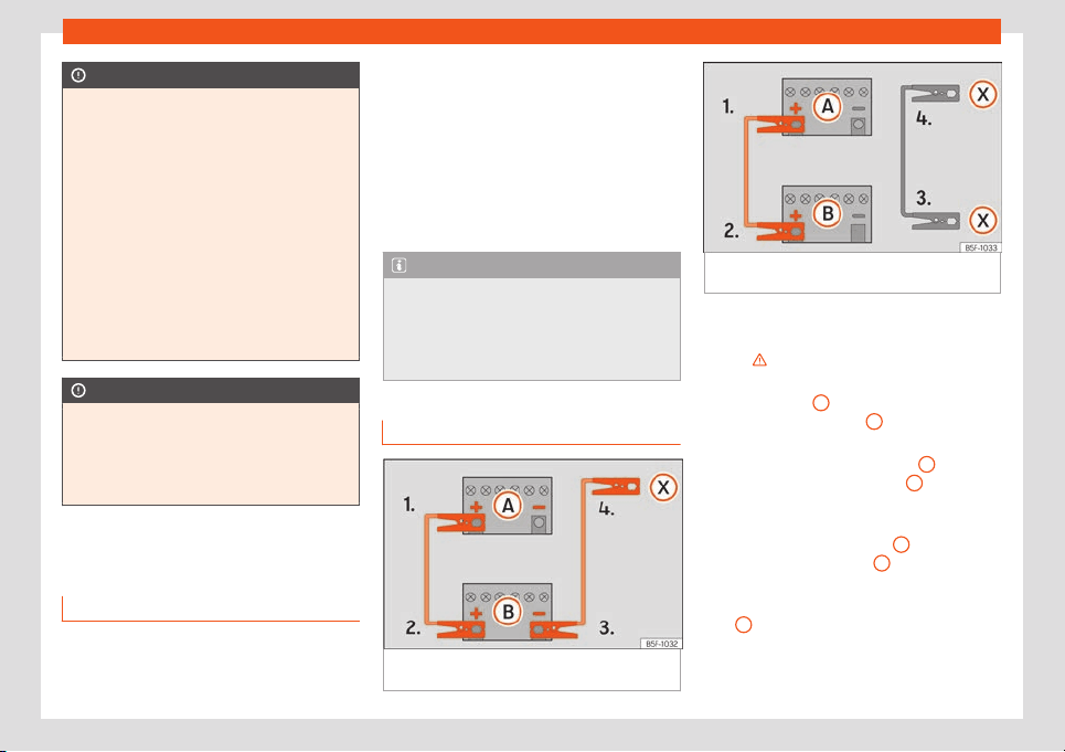
Self-help
CAUTION
●
Damaged or dirty windscreen wipers
could scratch the gl
ass.
●
If products containing solvents, rough
sponges or sharp objects are used to clean
the blades, the graphite layer will be dam-
aged.
●
Never use fuel, nail varnish remover, paint
thinner or similar products to clean the win-
dows.
●
In icy conditions, always check that the
wiper blades are not frozen to the glass be-
fore using the wipers. In cold weather, it
may help to leave the vehicle parked with
the wipers in service position
›››
page 49.
CAUTION
●
To prevent damage to the bonnet and the
wiper arms, only leav
e them in the service
position.
●
Before driving, always lower the wiper
arms.
Jump start
Jump l
eads
The jump lead must have a sufficient wire
cr
oss section.
If the engine f
ail
s t
o st
art because of a dis-
char
ged batt
ery, the battery can be connec-
ted to the battery of another vehicle to start
the engine.
Jump leads must comply with standard DIN
72553 (see cable manufacturer's instruc-
tions). The wire cross section must be at least
25 mm
2
for petrol engines and at least
35 mm
2
for diesel engines.
Note
●
The vehicles must not touch each other,
otherwise electricity coul
d flow as soon as
the positive terminals are connected.
●
The discharged battery must be properly
connected to the on-board network.
Jump start: description
Fig. 46 Diagram of connections for vehicles
without St
art St
op syst
em
Fig. 47 Diagram of connections for vehicles
with Start Stop system
Jump lead terminal connections
S
wit
ch off the ignition of both v
ehicl
es
›
›
›
.
Connect one end of the r
ed
jump l
ead t
o
the positiv
e
+
terminal of the vehicle
with the fl
at batt
ery
A
›
›
›
Fig. 46
.
Connect the other end of the
r
ed
jump
lead to the positive terminal
+
in the ve-
hicl
e pr
o
viding assist
ance
B
.
In v
ehicl
es without a St
art
-St
op syst
em:
connect one end of the
black jump lead
to the negative terminal
–
of the vehicle
pr
o
viding the curr
ent
B
›
›
›
Fig. 46.
In v
ehicl
es with a St
art
-stop system:
connect one end of the black jump lead
X
to a suitable ground terminal, to a sol-
id piece of met
al in the engine bl
ock
, or
t
o the engine bl
ock itself
›
›
›
Fig. 47.
»
1.
2.
3.
4a.
4b.
51
Emergencies
Connect the other end of the bl
ack
jump
l
ead
X
to a solid metal component bol-
t
ed t
o the engine bl
ock or t
o the engine
bl
ock itself of the v
ehicl
e with the flat
battery. Do not connect it to a point near
the battery
A
.
P
osition the l
eads in such a w
ay that
they cannot come int
o cont
act with any
mo
ving parts in the engine compart
-
ment.
Starting
Start the engine of the vehicle with the
boosting battery and let it run at idling
speed.
Start the engine of the vehicle with the
flat battery and wait for 2 or 3 minutes
until the engine is running.
Removing the jump leads
Before you remove the jump leads,
switch off the dipped beam headlights if
they are switched on.
Turn on the heater blower and heated
rear window in the vehicle with the flat
battery. This helps minimise voltage
peaks which are generated when the
leads are disconnected.
When the engine is running, disconnect
the leads in reverse order to the details
given above.
5.
6.
7.
8.
9.
10.
11.
Make sure the battery clamps have sufficient
metal-to-metal contact with the battery ter-
minals.
If the engine fails to start after about 10 sec-
onds, switch off the starter and try again after
about 1 minute.
WARNING
●
Please note the safety warnings ref
erring
to working in the engine compartment
›››
page 349.
●
The battery providing assistance must
have the same voltage as the flat battery
(12V) and approximately the same capaci-
ty (see imprint on battery). Failure to com-
ply could result in an explosion.
●
Never use jump leads when one of the
batteries is frozen. Danger of explosion!
Even after the battery has thawed, battery
acid could leak and cause chemical burns.
If a battery freezes, it should be replaced.
●
Keep sparks, flames and lighted ciga-
rettes away from batteries, danger of ex-
plosion. Failure to comply could result in an
explosion.
●
Observe the instructions provided by the
manufacturer of the jump leads.
●
Do not connect the negative cable from
the other vehicle directly to the negative
terminal of the flat battery. The gas emit-
ted from the battery could be ignited by
sparks. Danger of explosion.
●
Never attach the negative cable to fuel
syst
em components or the brake lines in
the other vehicle.
●
The non-insulated parts of the battery
clamps must not be allowed to touch. The
jump lead attached to the positive battery
terminal must not touch metal parts of the
vehicle, this can cause a short circuit.
●
Position the leads in such a way that they
cannot come into contact with any moving
parts in the engine compartment.
●
Do not lean on the batteries. This could
result in chemical burns.
Note
The vehicles must not touch each other,
otherwise electricity could flow as soon as
the positive t
erminals are connected.
Tow start and towing
Intr
oduction
Tow-starting means st
arting the engine of
the v
ehicl
e whil
e another pull
s it.
T
o
wing means one vehicle pulling another
that is not roadworthy.
Always consider the legal provisions relating
to tow-starting and towing.
52
Self-help
For technical reasons, towing a vehicle
with a dischar
ged batt
ery is not all
o
w
ed.
The jump st
ar
t should be used instead
›››
page 51.
If the vehicle comes with the Keyless Access
system, towing is only allowed with the igni-
tion on!
The vehicle battery drains if the vehicle is
towed with the engine switched off and the
ignition connected. Depending on the battery
charge status, the drop in voltage may be so
large, even after just a few minutes, that no
electrical device in the vehicle may work e.g.
the hazard warning lights. In vehicles with the
Keyless Access system, the steering wheel
could lock
›››
.
WARNING
A vehicle with no power should never be
towed.
●
During towing, nev
er switch off the igni-
tion with the starter button. Otherwise, the
electronic lock of the steering column
could suddenly get blocked and it would be
impossible to steer the vehicle. This could
cause an accident, serious injury and loss
of control of the vehicle.
●
If during towing the vehicle runs out of
power, stop towing immediately and re-
quest the assistance of specialist person-
nel.
WARNING
Vehicle handling and braking capacity
change considerably during towing. Please
observe the foll
owing instructions to mini-
mise the risk of serious accidents and in-
jury:
●
As the driver of the vehicle being towed:
–
You should depress the brake much
harder as the brake servo does not op-
erate. Pay the utmost attention to avoid
crashing into the towing vehicle.
–
More strength is required at the steer-
ing wheel as the power steering does
not operate when the engine is switch-
ed off.
●
As the driver of the towing vehicle:
–
Accelerate with particular care and
caution.
–
Avoid sudden braking and manoeuvres.
–
Brake earlier than usual and more
smoothly.
CAUTION
●
To avoid damaging the vehicle, for e
xam-
ple the paint, remove and replace the lid
and towing eye carefully.
●
Unburnt fuel could enter the catalytic
converter and damage it during towing.
Instructions for tow-starting
Vehicle's should not generally be tow-
started. The jump start should be used in-
st
ead
›››
page 51.
For technical reasons, towing the following
vehicles is not allowed:
●
Vehicles with an automatic gearbox.
●
If the vehicle battery is discharged, be-
cause in vehicles with the Keyless Access
locking and ignition system the steering re-
mains locked and the electronic parking
brake cannot be deactivated nor can the
electronic lock of the steering column be re-
leased if they are activated.
●
If the battery is flat, it is possible that the
engine control units may not operate correct-
ly.
How
ever, if the vehicle must absolutely be
tow-started (in the case of manual gear-
boxes):
●
Engage the 2nd or 3rd gear.
●
Keep the clutch pressed down.
●
Switch on the ignition and the hazard warn-
ing lights of both vehicles.
●
Once both vehicles are moving, release the
clutch.
●
Once the engine starts, press the clutch
and disengage the gear to avoid colliding
with the towing vehicle.
»
53
Emergencies
CAUTION
●
When tow-starting, unburnt fuel could
enter the cat
alytic converter and damage
it.
●
Do not tow a vehicle for more than 50 m
in attempt to start it. There is risk of dam-
age to the catalytic converter.
Note
The vehicle can only be tow-started if the
electronic parking brake and, if appropri-
ate
, the electronic lock of the steering col-
umn are deactivated. If the vehicle has no
power supply or there is an electric system
fault, the engine must be tow-started to de-
activate the electronic parking brake and
the electronic lock of the steering column.
Towing instructions
Towing requires some expertise and experi-
ence
, especially when using a t
o
w r
ope
. Both
driv
ers shoul
d be familiar with the difficulties
involved in towing. For this reason, inexper-
ienced drivers should abstain from towing.
During towing, it should be ensured that no
impermissible tractive forces or shocks are
generated. When towing on an unpaved
road, there is always a risk of overloading and
damaging the anchorage points.
During towing, the towing vehicle can signal
the change of direction even with the hazard
warning lights turned on. To do so, at the
same time, the turn signal lever must be oper-
ated with ignition switched on. Meanwhile, the
hazard warning lights will go off. When the
turn signal lever is returned to the rest posi-
tion, the hazard warning lights will be auto-
matically reactivated.
Notes for the driver of the towed vehicle
●
Leave the ignition on, so that the steering is
not blocked, and the electronic parking brake
may be deactivated and the turn signals and
wash/wipe operated.
●
More strength is required at the steering
wheel as the power steering does not oper-
ate when the engine is switched off.
●
You should depress the brake much harder
as the brake servo does not operate. Avoid
hitting the towing vehicle.
●
Bear in mind the information and instruc-
tions in the manual of the vehicle to be towed.
Notes for the driver of the towing vehicle
●
Accelerate with particular care and cau-
tion. Avoid sharp manoeuvres.
●
Brake earlier than usual and smoothly.
●
Bear in mind the information and instruc-
tions in the manual of the towed vehicle.
Tow rope or tow bar
It is safer for the vehicle to be towed using a
tow bar, avoiding damage to the vehicle. A
tow rope should only be used if a tow bar is
not available.
A tow rope should be slightly elastic to avoid
damage to both vehicles. It is advisable to
use a tow rope made of synthetic fibre or sim-
ilarly elastic material.
Only attach the tow rope or the tow bar to
the towing eyes provided or a towing bracket.
If the vehicle has a factory-fitted towing de-
vice, towing with a tow bar is only permitted
if it has been specially designed to be instal-
led on a tow hitch
›››
page 332.
When the vehicle has to be towed:
Check whether the vehicle may be towed
›››
page 55, Cases where towing the ve-
hicle is not permitted.
The vehicle can be towed using a tow bar or
tow rope in the normal way, with all four
wheels on the road; it can also be towed with
either the front or rear wheels lifted off the
road.
●
Switch the ignition on.
●
Put the gearbox lever in neutral or the se-
lector lever in the N
›››
page 253 position.
●
Do not allow the vehicle to be towed at
speeds of over 50 km/h (30 mph).
54
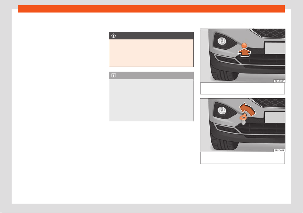
Self-help
●
The v
ehicl
e must not be t
o
w
ed further than
50 km (30 mil
es).
●
If a br
eakdown lorry is used, vehicles with
automatic transmission are only allowed to
be towed with the front wheels suspended.
Towing vehicles with four-wheel drive
(4Drive)
Four-wheel drive vehicles (4Drive) can be
towed using a tow bar or tow rope. If the vehi-
cle is towed with the front or rear axle sus-
pended, the engine must be switched off,
otherwise the transmission may be damaged.
Cases where towing the vehicle is not per-
mitted
●
If, due to a fault, the gearbox is out of lubri-
cant.
●
If the vehicle battery is discharged, be-
cause the steering remains locked and, if ap-
propriate, the electronic parking brake can-
not be deactivated or the electronic lock of
the steering column released.
●
If a distance above 50 km needs to be trav-
elled.
●
When, for example, after an accident, the
smooth rotation of the wheels or the steering
operation cannot be guaranteed.
When the vehicle is to tow another vehicle:
●
Observe legal requirements.
●
Keep in mind the instructions in the manual
on towing vehicles.
CAUTION
If there is no oil in the gearbox or no lubri-
cant in the automatic transmission the car
may only be towed with the driven wheel
s
lifted clear of the road, or transported on a
special car transporter or trailer.
Note
The vehicle can only be towed if the elec-
tronic parking brake and the electronic
lock of the st
eering column are deactiva-
ted. If the vehicle has no power supply or
there is an electric system fault, the engine
must be tow-started
›››
page 51 to deacti-
vate the electronic parking brake and the
electronic lock of the steering column.
Front towline anchorage
Fig. 48
On the right side of the front bumper:
r
emo
v
e the co
v
er
.
Fig. 49 On the right side of the front bumper:
t
o
wline anchor
age in position.
The housing of the removable towline an-
chor
age is on the right side of the fr
ont bump-
er underneath a co
v
er
›
›
›
Fig. 48.
The towing eye should always be kept in the
vehicle.
»
55
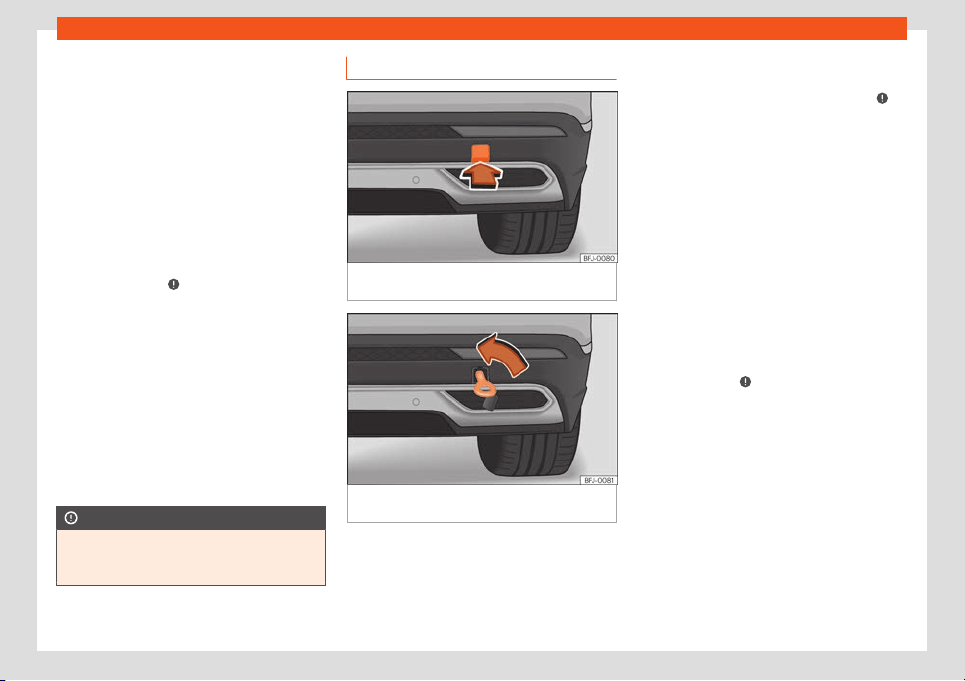
Emergencies
Bear in mind the instructions for towing
›
›
›
page 54
.
Fitting the t
o
wline anchor
age
●
Remove the towing eye from the vehicle
tool kit in the luggage compartment
›››
page 41.
●
Remove the cover by pressing down on its
base and leave it hanging from the vehicle
›››
Fig. 48.
●
Screw the towing eye in the housing by
turning it as far as it will go anticlock-
wise
›››
Fig. 49
›››
. Use a suitable object
that can compl
et
ely and secur
ely tight
en the
t
o
wing eye in its housing.
●
Aft
er towing, unscrew the towing eye
clockwise with a suitable object.
●
Insert the upper flange of the lid into the
opening of the bumper and press the lower
side of the lid until it is inserted into the bump-
er.
●
Clean the towing eye if necessary and then
store it in the luggage compartment along
with the other vehicle tools.
CAUTION
The towing eye must always be completely
and firmly tightened. Otherwise, it could be
released while t
owing and tow-starting.
Rear towline anchorage
Fig. 50
On the right side of the rear bumper:
r
emo
v
e the co
v
er
.
Fig. 51 On the right side of the rear bumper:
t
o
wline anchor
age in position.
The housing of the screw towing eye is on the
right side of the r
ear bumper behind a lid
›
›
›
Fig. 50
.
V
ehicl
es equipped as standard with a towing
bracket do not have any housing for the
screw towing eye behind the lid. In this case,
the tow hitch needs to be extracted or instal-
led and used for towing
›››
page 332,
›››
.
Bear in mind the instructions f
or t
o
wing
›
›
›
page 54
.
Assemble the rear towing eye (cars with-
out a factory-equipped towing bracket)
●
Remove the towing eye from the vehicle
tool kit in the luggage compartment
›››
page 41.
●
Press the bottom side of the lid
›››
Fig. 50 to
unclip it.
●
Remove the lid and let it hang from the ve-
hicle.
●
Screw the towline anchorage into the hous-
ing by turning it as far as it will go anticlock-
wise
›››
Fig. 51
›››
. Use a suitable object that
can compl
et
ely and secur
ely tight
en the t
o
w-
ing eye in its housing.
●
Aft
er towing, unscrew the towing eye
clockwise with a suitable object.
●
Insert the upper flange of the lid into the
opening of the bumper and press the lower
side of the lid until the upper flange is inserted
into the bumper.
●
Clean the towing eye if necessary and then
store it in the luggage compartment along
with the other vehicle tools.
56
Fuses and bulbs
CAUTION
●
The towing eye must always be com-
pletely and firmly tight
ened. Otherwise, it
could be released while towing and tow-
starting.
●
If the vehicle is factory-equipped with a
towing bracket, it is only allowed to tow
with a tow bar if this has been specially de-
signed to be installed with a tow hitch. If an
unsuitable tow bar is used, both the tow
hitch and the vehicle may be damaged. In-
stead, a tow rope should be used.
Fuses and bulbs
Fuses
Intr
oduction
In general, a fuse can be assigned to various
electrical components. Likewise, an electrical
component can be prot
ected by several
fuses.
Only replace fuses when the cause of the
problem has been solved. If a newly inserted
fuse blows after a short time, you must have
the electrical system checked by a special-
ised workshop as soon as possible.
WARNING
The high voltages in the electrical system
can give serious electrical shocks, causing
burns and even death!
●
Never t
ouch the electrical wiring of the
ignition system.
●
Take care not to cause short circuits in
the electrical system.
WARNING
Using unsuitable fuses, repairing fuses or
bridging a current circuit without fuses can
cause a fire and serious injury.
●
Never use a fuse with a higher value
. Only
replace fuses with a fuse of the same am-
perage (same colour and markings) and
size.
●
Never replace a fuse by a met
al strip, sta-
ple or similar.
CAUTION
●
T
o prevent damage to the vehicl
e's elec-
tric system, before replacing a fuse always
turn off the ignition, the lights and all elec-
trical elements and remove the key from
the ignition.
●
Protect the fuse boxes when open to pre-
vent the entry of dust or humidity as they
can damage the electrical system.
Note
●
One component may have more than one
fuse.
●
Several components may run on a singl
e
fuse.
●
In the vehicle, there are more fuses than
those indicated in this chapter.
57
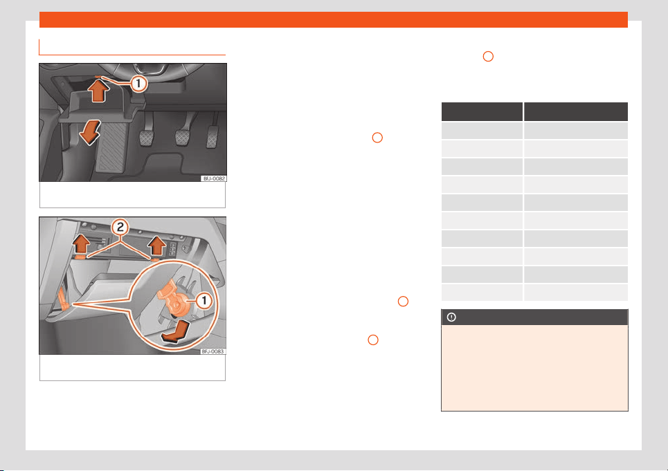
Emergencies
Fuses inside the vehicle
Fig. 52
On the dashboard on the driver's side
(l
eft
-hand driv
e): fuse bo
x co
v
er
.
Fig. 53
glove compartment (right hand drive):
fuse bo
x access.
Opening and closing the fuse box situated
bel
o
w the dash panel (l
eft
-hand st
eering
wheel)
●
Open the st
or
age compartment on the
driver side
›››
Fig. 52.
●
In this case, empty the storage compart-
ment.
●
Press the locking lid
›››
Fig. 52
1
upwards,
in the dir
ection of the arr
o
w
, and at the same
time open the st
or
age compartment e
ven
more and remove it until the fuse box is ac-
cessible.
●
To attach the storage compartment, insert
it in the openings of the dashboard and press
it until you hear it click on both sides. Close it.
Fuses behind the glove compartment
(right-hand steering wheel)
●
Open the glove compartment and, if nec-
essary, empty it.
●
Move the braking element
›››
Fig. 53
1
into
the support hol
e f
acing do
wnw
ar
ds and r
e-
mo
ve it to one side.
●
Press the end axes
›››
Fig. 53
2
upwards, in
the dir
ection of the arr
o
ws, and at the same
time open the gl
o
v
e compartment e
ven more.
●
To mount the glove compartment, place it
in the correct position. Insert the braking ele-
ment into the hole of the base and move it
upwards until you hear it click. Carefully
press the glove compartment to the front,
against the resistance of the end axes
›››
Fig. 53
2
.
Identifying fuses bel
o
w bel
o
w the dash-
boar
d by col
ours
Colour Amp rating
Black 1
Purple 3
Light brown 5
Brown 7.5
Red 10
Blue 15
Yellow 20
White or transparent 25
Green 30
Orange 40
CAUTION
●
Always carefully remove the fuse bo
x
covers and refit them correctly to avoid
problems with your vehicle.
●
Protect the fuse boxes when open to
avoid the entry of dust or humidity. Dirt and
humidity inside fuse boxes can cause dam-
age to the electrical system.
58
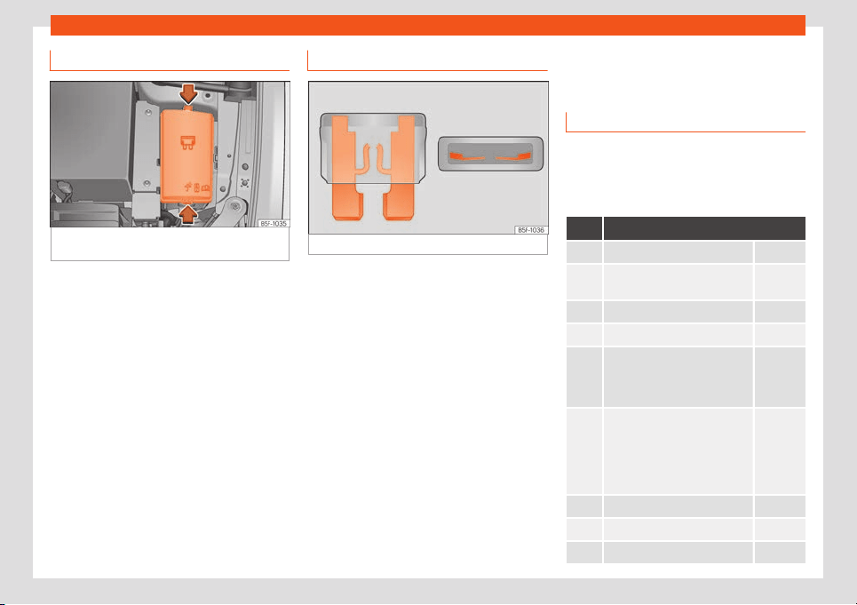
Fuses and bulbs
Fuses in the engine compartment
Fig. 54
In the engine compartment: fuse box
co
v
er
.
To open the engine compartment fuse box
●
Open the bonnet
›
›
›
page 349
.
●
Pr
ess the l
ocking t
abs to release the fuse
box cover
›››
Fig. 54.
●
Then lift the cover out.
●
To fit the cover, place it on the fuse box.
Push the locking tabs down until they click
audibly into place.
Replace a blown fuse
Fig. 55
Image of a blown fuse.
Preparations
●
Switch off the ignition, lights and all electri-
cal equipment.
●
Open the corresponding fuse box
›
›
›
page 58
,
›
›
›
page 59.
Recognise a blown fuse
A fuse is blown if its metal strip is ruptured
›››
Fig. 55.
●
Point a lamp at the fuse to see if it has
blown.
To replace a fuse
●
Remove the fuse.
●
Replace the blown fuse by one with an
identical amperage rating (same colour and
markings) and identical size.
●
Replace the cover again or close the fuse
box lid.
Fuse placement
Only replace fuses with a fuse of the same
amperage (same colour and markings) and
size.
Fuses in the vehicle int
erior
No. Consumers/Amps
1 Adblue (SCR) 30
4
DWA warning horn, on-board
computer
7.5
5 Gateway 7.5
6 Aut
omatic gearbox lever 7.5
7
Air conditioning and heating
control panel, back window
heating, auxiliary heating, rear
heating
10
8
Diagnosis, electronic parking
br
ak
e s
wit
ch, light s
wit
ch, r
e-
verse light, interior lighting, driv-
ing mode, lit-up door sill,
light/humidity/rain sensor,
curve lighting control unit
7.5
9 Steering column control unit 7.5
10 Radio display 7.5
11 On-board computer control unit 40
»
59

Emergencies
No. Consumers/Amps
12 Infotainment radio 20
13 Driver seat belt pre-tensioner 25
14 Air conditioner fan 40
15 Steering column release 10
16
GSM signal reception and sta-
bilisation, mobile phone inter-
face, USB connections control
unit
7.5
1
7
Dashboard, OCU navigation in-
t
erf
ace
7.5
18
Surr
oundings camer
a and r
ear
camer
a contr
ol unit
7.5
19 Kessy 7.5
20 SCT 1.5 L engine vacuum pump 7.5/15
21 4x4 Haldex Control Unit 15
22 Trailer 15
23 Electric sunroof 20
24 On-board computer 40
25 Left doors 30
26 Heated seats 30
27 Interior light 30
28 Trailer 25
31 Electrical lid control unit 30
No. Consumers/Amps
32
Control unit for parking aid,
front camera and radar
10
33 Airbag 7.5
34
Rev
erse switch, climate sensor,
electrochromic mirror, electr
o-
mechanical brake
7.5
35 Diagnosis connector 7.5
38 Trailer 25
39 Right doors 30
40/1 12V socket 20
41
Passenger seat belt pre-ten-
sioner
25
42 Central locking 40
43 Digital sound control unit 30
44 Trailer 15
45 Electric driver's seat 15
47 Rear window wiper 15
49 Starter motor 7.5
51 Rear AC 25
52 Driving mode. 15
53 Heated rear window 30
Fuse arrangement in engine compartment
No. Consumers/Amps
1 ABS/ESP control unit 25
2 ABS/ESP control unit 40/60
3
Engine control unit (petrol/die-
sel)
15/30
4
Engine sensors, electric fans,
pressure regulator, fl
ow rate
meter, spark plug relay (die-
sel), PTC relays
7.5/10
5 Engine sensors 10
6 Brake light sensor 7.5
7 Engine power supply 7.5/10
8 Lambda probe 10/15
9 Engine 10/20
10 Fuel pump control unit 15/20
11 PTC 40
12 PTC 40
13
Automatic transmission oil
cooling pump
30
15 Horn 15
16 Ignition coil relay (2.0 petrol) 20
17
Engine control unit, ABS/ESP
contr
ol unit, primary relay
7.5
60
Fuses and bulbs
No. Consumers/Amps
18
Terminal 30 (positive refer-
ence)
7.5
19 Front windscreen washer 30
21 Automatic gearbox control unit 15
22 Engine control unit 7.5
23 Starter motor 30
24 PTC 40
36 Left headlight 15
37 Parking heating 20
38 Right headlight 15
Note
●
In the vehicle, there are more fuses than
those indicat
ed in this chapter. These
should only be changed by a specialised
workshop.
●
Positions not containing a fuse do not ap-
pear in the following tables.
●
Some of the equipment listed in the ta-
bles below pertain only to certain versions
of the model or are optional extras.
●
Please note that the above lists, while
correct at the time of printing, are subject
to change.
Bulbs
Changing bulbs
Your vehicle is equipped with full-lead head-
light systems.
Full-LED headlights handle all light functions
(daylight, side light, turn signal, dipped beam
and route light) with light emitting diodes
(LEDs) as a light sour
ce.
Full-LED headlights are designed to last
the lifetime of the car and light bulbs can-
not be replaced. In case of headlight fail-
ure, go to an authorised workshop to have
it replaced.
Side turn signals
The side turn signals are LEDS and are inte-
grated in the exterior mirrors.
In case of failure, go to an authorised work-
shop to have them replaced.
Additional brake light
Taking into account that it consists of LED
bulbs, the change should be made at a tech-
nical service centre.
61
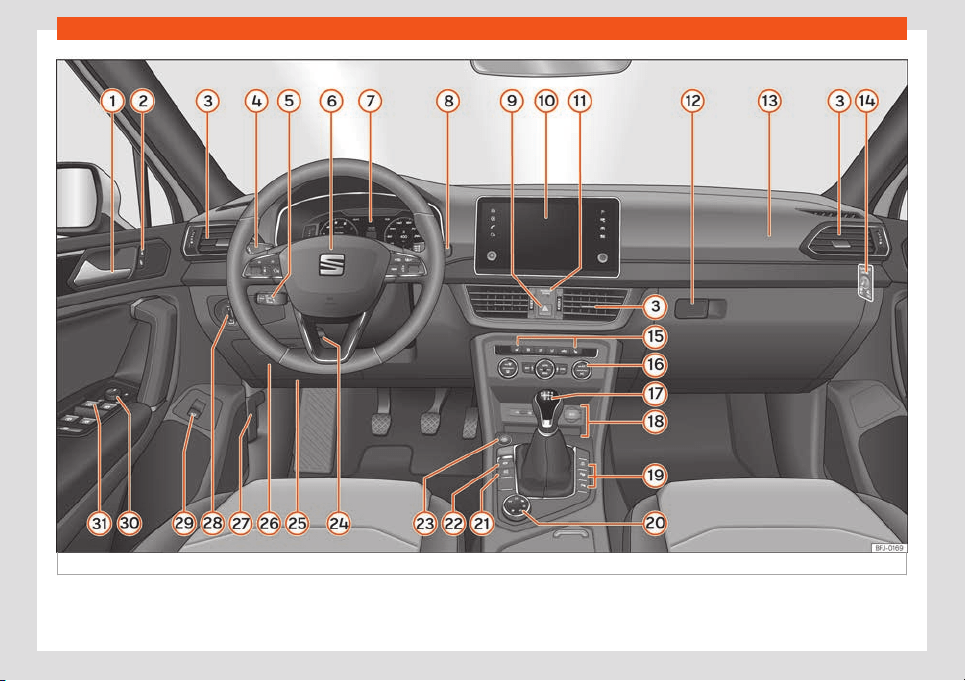
Operation
Fig. 56 Instruments and controls.
62

Controls and displays
Operation
Contr
ol
s and displ
ays
Int
erior vie
w
Ov
ervie
w
Door handle
Central locking switch . . . . . . . . . . . . . . . 92
Air vents
. . . . . . . . . . . . . . . . . . . . . . . . . . . . . . 158
Control lever for:
–
Turn signals and main beam
headlights . . . . . . . . . . . . . . . . . . . . . . . . . . 112
–
Cruise control system (GRA) and
speed limit
er . . . . . . . . . . . . . . . . . . . . . . .268, 270
–
Driver assistance systems . . . . . . . . . 79
According to features, lever for:
–
Speed limiter . . . . . . . . . . . . . . . . . . . . . . . 270
–
Adaptive Cruise Control (ACC) . . . 277
Steering wheel with horn and
–
Driver airbag . . . . . . . . . . . . . . . . . . . . . . . 25
–
On-board computer controls . . . . . 78
–
Controls for radio, telephone,
navigation and speech dialogue
system . . . . . . . . . . . . . . . . . . . . . . . . . . . . . . 165
–
Paddle levers for tiptronic gear-
shift (automatic gearbox) . . . . . . . . . 256
1
2
3
4
5
6
Digital dashboard (SEAT Digital
Cockpit) . . . . . . . . . . . . . . . . . . . . . . . . . . . . . . 64
Control lever for:
–
Windscr
een wipers and w
asher . . . 1
18
–
Wipe and w
ash syst
em
. . . . . . . . . . . . 1
18
Hazard warning lights . . . . . . . . . . . . . . . . 115
Infotainment System . . . . . . . . . . . . . . . . . 165
Front passenger airbag disconnec-
tion display . . . . . . . . . . . . . . . . . . . . . . . . . . . 27
Depending on the equipment, glove
compartment with: . . . . . . . . . . . . . . . . . . . 146
–
CD player* and/or SD card* . . . . . 206
Front passenger airbag . . . . . . . . . . . . . . 26
Switch for switching off the front
passenger airbag . . . . . . . . . . . . . . . . . . . . 27
Thermal seat controls . . . . . . . . . . . . . . . 159
Depending on the equipment, con-
trols for:
–
Manual AC . . . . . . . . . . . . . . . . . . . . . . . . . 155
–
Automatic AC (Climatronic) . . . . . . . 154
Gear lever for:
–
Manual gearbox . . . . . . . . . . . . . . . . . . . 253
–
Automatic gearbox . . . . . . . . . . . . . . . . 254
Area for:
–
USB/AUX-IN input. . . . . . . . . . . . . . . . . . . 244
–
12 volt socket . . . . . . . . . . . . . . . . . . . . . . . 150
–
Connectivity Box/Wireless Charg-
er* . . . . . . . . . . . . . . . . . . . . . . . . . . . . . . . . . . 244
7
8
9
10
11
12
13
14
15
16
17
18
–
St
or
age compartment
. . . . . . . . . . . . . 145
Depending on the equipment, but
-
t
ons f
or:
–
St
art-Stop system . . . . . . . . . . . . . . . . . 250
–
Parking aid system (Park As-
sist) . . . . . . . . . . . . . . . . . . . . . . . . . . . . . . . . . 306
–
Park Pilot system . . . . . . . . . . . . . . . . . . . 314
–
Peripheral view system (Top View
Camera) . . . . . . . . . . . . . . . . . . . . . . . . . . . 323
Rotating control(Driving Experience
button) for driving modes . . . . . . . . . . . . 263
Auto Hold switch . . . . . . . . . . . . . . . . . . . . . 301
Electronic parking brake switch . . . . . 299
Start-up push button (Keyless Ac-
cess closing and start-up sys-
tem) . . . . . . . . . . . . . . . . . . . . . . . . . . . . . . . . . . . 246
Steering column adjustment lev-
er . . . . . . . . . . . . . . . . . . . . . . . . . . . . . . . . . . . . . 14
Location of the knee airbag . . . . . . . . . 28
Storage compartment / fuse box . . . 57
Bonnet lock release . . . . . . . . . . . . . . . . . . 350
Headlight switch . . . . . . . . . . . . . . . . . . . . . 109
Button to open rear lid . . . . . . . . . . . . . . . 101
Control for the electric adjustment
of the exterior mirrors . . . . . . . . . . . . . . . . 121
Electric windows . . . . . . . . . . . . . . . . . . . . . 104
»
19
20
21
22
23
24
25
26
27
28
29
30
31
63
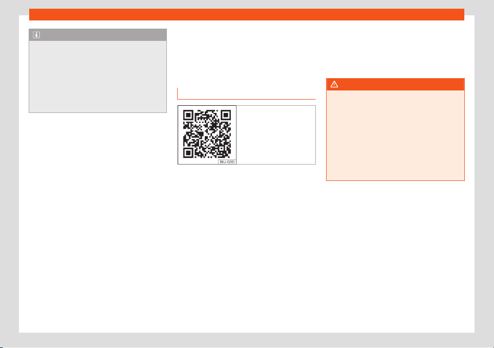
Operation
Note
●
Some of the equipment listed in this sec-
tion is only fitted on certain models or are
optional e
xtras.
●
The arrangement of switches and con-
trols on right-hand drive models* may be
slightly different from the layout shown in
›››
page 62. However, the symbols used to
identify the controls are the same.
Instruments and warn-
ing/contr
ol l
amps
Instrument panel
Intr
oduction
Fig. 57 Related video:
Dash panel
After switching the engine on with a 12-volt
batt
ery that is heavily dischar
ged or ne
wly
changed some syst
em settings (such as the
time
, the dat
e
, the personalised comfort set-
tings and the programming) might be altered
or deleted. Check and correct these settings
once the battery is sufficiently charged.
WARNING
Any distraction may lead to an accident,
with the risk of injury.
●
Do not operate the instrument panel con-
trols when driving.
●
To reduce the risk of accident and injury,
only make adjustments to the instructions
on the scr
een of the instrument panel and
to the instructions on the screen of the Info-
tainment system when the vehicle is sta-
tionary.
64
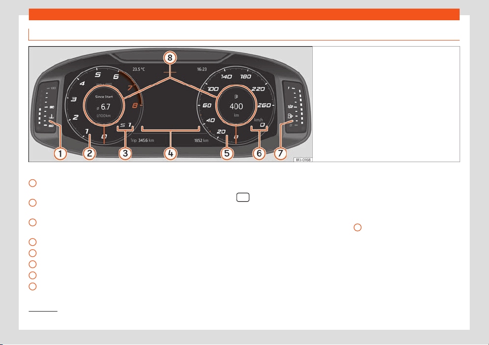
Instruments and warning/control lamps
Digital dashboard (SEAT Digital Cockpit)
Fig. 58 SEAT Digital Cockpit on the instrument
panel (classic view).
Details of the instruments:
Engine cool
ant t
emper
at
ur
e displ
ay
›
››
page 76
Revolution counter. Revolutions per mi-
nute the engine is running
›››
page 75.
Gear engaged or position of the selec-
tor lever currently selected
Screen display
›››
page 67
Speedometer
Digital speed display
Fuel gauge
›››
page 76.
Information Profile
›››
page 65.
1
2
3
4
5
6
7
8
The Digital SEAT Cockpit is an instrument
panel digit
al with monochr
ome scr
een in col
-
our high r
esolution. It has a 3 vie
ws accessi-
bl
e using the button
of the multifunction
st
eering wheel. By sel
ecting diff
er
ent inf
or
-
mation pr
ofiles, indications other than the
classic circular instruments can be displayed,
such as navigation data, multimedia informa-
tion or travel data.
The 3 views are:
Classic View
Digital maps (no information profiles)
Semicircular watches
–
–
–
All views will display information on the
screen about audio, phone, travel data, vehi-
cle status, navigation
1)
and driving aids
1)
.
In Classic View and Semicircular watches it is
possible to customise the information dis-
played under Information Profiles
›››
Fig. 58
8
.
Inf
ormation pr
ofil
es
With the
INSTRUMENT CLUSTER option (inf
o-
t
ainment butt
on > View > Instrument
cluster) you can choose between the dif-
ferent information display options that will be
shown in the SEAT Digital Cockpit.
»
1)
Depending on the version.
65
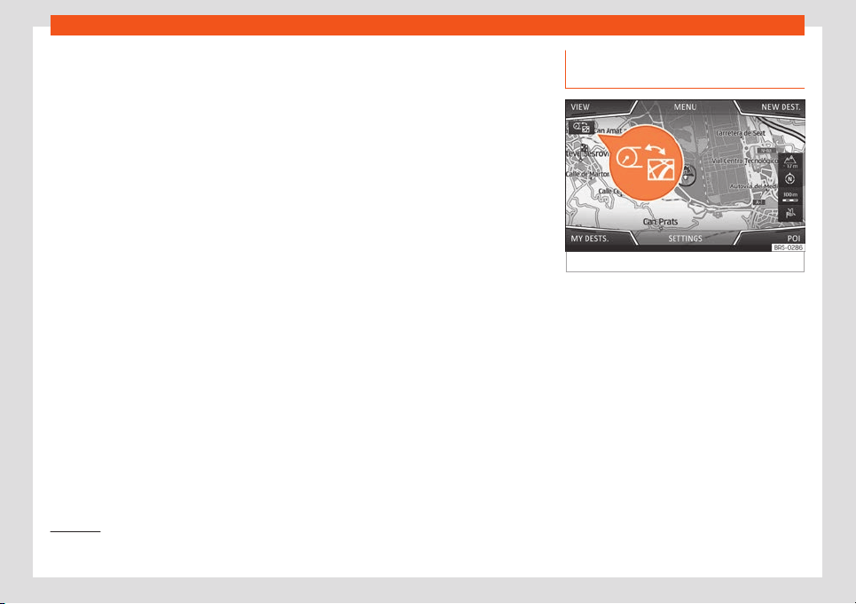
Operation
Classic View
The r
e
v
olutions per minut
e and speedomet
er
needl
es appear al
ong the entire length
›››
Fig. 58.
View 1, 2, 3 or AUTOMATIC*
1)
Personalisation of the information that ap-
pears in the Digital SEAT Cockpit. Only 2 of
these items of information can be displayed
at the same time, but the user chooses which
to display, and in what order, by moving the
finger vertically over the dials.
Depending on the version, the Views can be
memorised by exiting the menu or keeping
the View button pressed.
●
Consumption. Graphic representation of
the current consumption and digital display
of the average consumption.
●
Audio. Digital display of the current audio
playback.
●
Altitude. Digital display of the current alti-
tude above sea level.
●
Compass. Digital display of the compass.
●
Information about the final destination.
Digital display of the remaining travelling
time, distance to the destination and the esti-
mated time of arrival.
●
Operating range. Digital display of the re-
maining range.
●
Travel time.
●
Route guidance.
●
Journey. Digital display of the distance
travelled.
●
Assistance systems. Graphic representa-
tion of different assistance systems.
●
Traffic signs. Display of traffic signs detec-
ted.
●
Navigation. Graphical representation of
the navigation with arrows.
It may vary based on the features, the num-
ber and the contents of the selectable infor-
mation profiles..
Navigation map in the SEAT Digital
Cockpit*
Fig. 59
Infotainment system:: map transfer key
Depending on the features, the SEAT Digital
Cockpit can displ
ay a det
ail
ed map
. T
o do
this, sel
ect the
Navigation option in the
menu menu on the instrument panel
›››
page 68.
Depending on the features or the navigation
map, it can be shown in the Digital SEAT
Cockpit or on the Infotainment system or on
both at the same time. If it is displayed only in
the Infotainment system, the SEAT Digital
Cockpit will only display the arrows for ma-
noeuvres.
1)
Pre-set information depending on the “Driving
mode” selected.
66

Instruments and warning/control lamps
Transfer of navigation map
Using the map tr
ansf
er k
ey
›
›
›
Fig. 59
, the
map is transferred from the Infotainment sys-
tem to the Digital SEAT Cockpit and vice ver-
sa.
Using the right thumbwheel of the multifunc-
tion steering wheel, in the Navigation menu,
you can transfer the map back to the Info-
tainment System.
Status display
Possible indications on the instrument
panel displ
ay
Diff
er
ent pieces of inf
ormation can be dis-
pl
ayed on the scr
een of the instrument panel,
depending on the f
eatures of the vehicle.
●
Doors, bonnet and rear lid open
●
Warning and information messages
●
Odometer
●
Time
›››
page 75
●
Indications of the radio and navigation sys-
tem
●
Indications of the phone
●
Outside temperature
●
Indications of the compass
●
Selector lever positions
●
Gear-change recommendation
›››
page 261
●
Display of travel data (multifunction dis-
play) and menus for different settings
›››
page 68
●
Service interval display
›››
page 77
●
Speed warning
›››
page 69
●
Speed warning for winter tyres
●
Start-Stop system status display
›››
page 250
●
Signs detected by the traffic signal detec-
tion system
›››
page 72
●
Indication of active cylinder management
status (ACT
®
)
›››
page 266
●
Low consumption driving
●
Identifying letters on engine (LDM)
●
Driver assistance system display
›››
page 268
●
Copyright
Doors, bonnet and rear lid open
When the vehicle is unlocked and while driv-
ing, the instrument panel display shows if any
of the doors, the bonnet or rear lid are
opened and, in some cases, it is also indica-
ted by an audible warning. The display may
vary according to the type of instrument pan-
el fitted.
Selector lever positions (DSG
®
dual clutch
shift)
The current position of the selector lever is
shown on the side of the lever and on the in-
strument panel display. When the lever is in
the D/S position or in the Tiptronic position, in
some cases, the gear engaged in each case
is shown on the instrument panel display .
Outside temperature indicator
If the outside temperature is lower than ap-
proximately +4 °C (+39 °F), the “ice crystal
symbol” on the outside temperature dis-
play also lights up. This symbol remains lit un-
til the outside temperature exceeds +6 °C
(+43 °F)
›››
.
When the v
ehicl
e is st
ationary, when the aux-
iliary heat
er is s
wit
ched on or when driving at
v
ery low speeds, the outside temperature in-
dicated may be higher than the actual tem-
perature due to the heat produced by the en-
gine.
The margin of measurement ranges from
-45 °C (-49 °F) to +76 °C (+169 °F).
Gear-change recommendation
While driving, the instrument panel of certain
vehicles may indicate a gear recommenda-
tion for saving fuel
›››
page 261.
»
67
Operation
Odometer
The od
omet
er
r
egist
ers the t
ot
al distance
travelled by the car.
The partial odometer (trip) shows the dis-
tance travelled since the last time it was reset
to zero.
●
Set the odometer to zero via the Infotain-
ment system or the multifunction steering
wheel
›››
page 69.
Speed warning for winter tyres
If the maximum speed set is exceeded, this is
displayed on the instrument panel
›››
page 68.
Speed warning settings can be changed in
the infotainment system, by pressing the info-
tainment button > SETTINGS > Driver
assistance
›››
page 82.
Indications of the compass
Depending on the equipment, when the igni-
tion is on, the instrument panel display indi-
cates the direction in which you are driving
with a symbol, e.g. NW for Northwest.
When the Infotainment system is on and there
is no route guidance active, the graphic rep-
resentation of a compass is also shown.
Low consumption driving *
Depending on the equipment, when driving,
the display appears on the instrument
panel when the vehicle is in low consumption
status due to active cylinder management
(ACT
®
)*
›››
page 266.
Copyright
Legal text about the property rights and
copyrights of the instrument cluster.
WARNING
Even when the outside temperature is high-
er than freezing temperature
, some roads
and bridges could be frozen.
●
The “ice crystal symbol” indicates that
there may be a risk of freezing.
●
At outside temperatures above +4 °C
(+39 °F), there may be ice even when the
“ice crystal symbol” is not on.
●
The outside temperature sensor takes a
guideline measurement.
Note
●
There are different instrument panels and
theref
ore the versions and instructions on
the display may vary. In the case of dis-
plays without warning or information texts,
faults are indicated exclusively by the con-
trol warning lamps.
●
Some indications on the instrument panel
screen may be concealed by a sudden
event, e.g. an incoming call.
●
Depending on the equipment, some set-
tings and instructions can be carried out or
displ
ayed on the infotainment system as
well.
●
If there are several warnings at the same
time, the symbols will be displayed one af-
ter the other for a few seconds. The sym-
bols will stay on until you remove the
cause.
●
If when switching on the ignition warnings
are shown about existing faults, it might not
be possible to change the settings or show
the information as described. In this case,
go to a specialised workshop and request a
repair.
Instrument panel menus
The number of menus and information items
av
ail
abl
e will depend on the v
ehicl
e
’
s elec-
tronics and features.
A specialised workshop can programme or
modify additional functions, according to the
vehicle equipment. SEAT recommends visiting
a SEAT dealership for this.
Some menu options can only be read when
the vehicle is stationary.
■
Driving data
›››
page 69
68

Instruments and warning/control lamps
■
Assist
ance syst
ems
■
L
ane Assist On/Off
›
›
›
page 286
■
Fr
ont Assist On/Off
›››
page 273
■
Blind spot detector On/Off
›››
page 291
■
ACC (only display)
›››
page 277
■
Navigation
■
Audio
■
Telephone
■
Vehicle status
›››
page 70
Service Menu
In the Service menu various settings can be
adjust
ed depending on the f
eat
ur
es.
Open the Service menu
T
o open up the
Service menu, sel
ect the
Range information profile while in the Driv-
ing data menu, and keep the
key press-
ed on the multifunction st
eering wheel f
or ap-
pr
o
ximat
ely 4 seconds. When it is r
el
eased,
the Service menu will be displayed. Now
you can browse through the menu using the
keys on the multifunction steering wheel as
usual.
Restart the service interval display
Select the Service menu and follow the in-
structions on the screen of the instrument
panel.
Restart the oil service
Select the Restore Oil service menu and
follow the instructions on the instrument pan-
el display.
Restart journey data
Select the Reset trip menu and follow the
instructions on the instrument panel display
to reset the value.
Identifying letters on engine (LDM)
Select the menu Engine code. The identify-
ing letters of the engine will be shown on the
instrument cluster display at the bottom left.
Setting the clock
Select the Time menu and set the correct
time by turning the right thumbwheel of the
multifunction steering wheel.
Driving data indicator (multifunc-
tion display)
The display of the travel data (multifunction
display) shows different values about the
journey and the consumption.
Change from one displ
ay to another
●
Turn the right thumbwheel of the multifunc-
tion steering wheel
›››
page 78.
Changing memory
●
While in Travel data > General infor-
mation press
on the multi-function steer-
ing wheel t
o s
wit
ch betw
een the 3 memo-
ries
1)
:
Since start: The memory is del
et
ed if
the journey is int
errupted for more than 2
hours.
Since refuelling: Display and stor-
age of the journey data and the con-
sumption values collected. When refuel-
ling, the memory is deleted.
Long-term: This memory contains trav-
el data up to a maximum of 19 hours and
59 minutes or 99 hours and 59 minutes,
or up to a maximum of 1999.9 km or
»
–
–
–
1)
This will show all data on the display at the
same time: distance travelled, average con-
sumption, av
erage speed and autonomy.
69

Operation
9999.9 km. When one of these values is
e
x
ceeded (v
aries depending on the v
er
-
sion of the instrument panel), the memo-
ry is del
et
ed.
Delete journey data presets
●
Select the memory that you wish to erase.
●
Keep the
button on the multi-function
st
eering wheel pr
essed f
or appr
o
ximat
ely 2
seconds.
Sel
ect the instructions
In the Infotainment system, in the menu Vehi-
cle settings, you can display different travel
data
›››
page 82.
Current consumption: The current
fuel consumption display operates
throughout the journey, in litres/100 km;
and with the engine running and the ve-
hicle stopped, in litres/hour.
Average consumption: The average
fuel consumption is displayed after driv-
ing for approximately 300 metres.
Travelling time: This indicates the
hours (h) and minutes (min) since the ig-
nition was switched on.
Range: Approximate distance in km that
can still be travelled if the same driving
style is maintained.
–
–
–
–
AdBlue range or : Approximate
distance in km that can still be travelled
with the current level of the AdBlue
®
tank
with the same driving style. The indica-
tion appears from a range of less than
2,400 km and cannot be deactivated.
1)
Distance: Distance covered in km (m)
after switching on the ignition.
Average speed: The average speed
will be shown after driving for approxi-
mately 100 metres.
Digital speed display: Current
speed displayed in digital format.
Convenience consumers: Displays a
list of the connected comfort systems
that increase energy consumption, e.g.
air conditioning.
Setting a speed warning
●
Select the display Warning at --- km/h
or Speed warning at --- mph.
●
Press the
button on the multi-function
st
eering wheel t
o memorise the curr
ent
speed and activ
at
e the w
arning.
●
Activ
ate: set the desired speed within 5
seconds by rotating the wheel on the multi-
function steering wheel. Next, press the
button again or wait several seconds. The
speed is st
or
ed and the w
arning activ
at
ed.
–
–
–
–
–
●
Deactiv
at
e: press the
button. The stored
speed is del
et
ed.
The w
arning can be adjust
ed f
or speeds be-
tw
een 30 km/h (
18 mph) and 250 km/h
(155 mph).
Display Oil temperature
The engine reaches its operating tempera-
ture when, under normal driving conditions,
the oil temperature is between 80°C (176°F)
and 120°C (248°F). If a great effort is required
from the engine and the outside temperature
is high, the engine oil temperature may in-
crease. This does not present any problem as
long as the warning lamps or
›››
page 353 do not appear on the display.
Warning and information messages
(Vehicle status)
The system runs a check on certain compo-
nents and functions when the ignition is
s
wit
ched on and whil
e the v
ehicl
e is mo
ving.
F
aults displayed on the instrument panel as
red and yellow warning symbols accompa-
nied with messages and, depending on the
case, even an audible warning
›››
page 79.
The representation of the messages and
1)
Not available in all countries.
70
Instruments and warning/control lamps
symbols may vary depending on the version
of the instrument panel.
Existing f
aults can al
so be check
ed manually.
T
o do so
, open the menu
Vehicle status or
Vehicle
›
››
page 68.
Priority 1 warning (red)
The symbol lights up or flashes (in part ac-
companied by audible warnings). Stop
driving! Danger! Check the fault and elimi-
nate the cause. If necessary, seek professio-
nal assistance.
Priority 2 warning (yellow)
The symbol lights up or flashes (in part ac-
companied by audible warnings). Operating
faults or the lack of operating fluids can
cause damage to the vehicle or a fault.
Check the faulty function as soon as possible.
If necessary, seek professional assistance.
Information message
It provides information about processes in the
vehicle.
Driver alert system (break recom-
mendation)*
Fig. 60
On the instrument panel display: driv-
er al
ert syst
em symbol
.
Function and operation
F
atigue det
ection det
ermines the driving be-
haviour of the driv
er when st
arting a journey,
making a cal
cul
ation of tiredness. This is con-
stantly compared with the current driving be-
haviour. If the system detects that the driver is
tired, an audible warning is given with a
sound and an optic warning is shown with a
symbol and complementary message on the
instrument panel display
›››
Fig. 60. The mes-
sage on the instrument panel display is
shown for approximately 5 seconds, and de-
pending on the case, is repeated. The system
stores the last message displayed.
The message on the instrument panel display
can be switched off by pressing the
but-
ton on the multi-function steering wheel
›
›
›
page 7
8
.
The message can be r
ecall
ed to the instru-
ment panel display using the multifunction
display
›››
page 69.
Conditions of operation
Driving behaviour is only calculated on
speeds above about 65 km/h (40 mph) up to
around 200 km/h (125 mph).
Switching on and off
Drowsiness detection can be activated or de-
activated in the Easy Connect system with
the key > SETTINGS > Driver assis-
tance
›››
page 82. A mark indicates that the
adjustment has been activated.
System limitations
The Fatigue detection has certain limitations
inherent to the system. The following condi-
tions can limit the Fatigue detection or pre-
vent it from functioning.
●
At speeds below 65 km/h (40 mph)
●
At speeds above 200 km/h (125 mph)
●
When cornering
●
On roads in poor condition
●
In unfavourable weather conditions
●
When a sporty driving style is employed
»
71
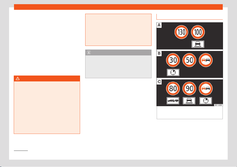
Operation
●
In the e
v
ent of a serious distr
action t
o the
driv
er
F
atigue det
ection will be restored when the
vehicle is stopped for more than 15 minutes,
when the ignition is switched off or when the
driver has unbuckled their seat belt and
opened the door.
In the event of slow driving during a long peri-
od of time (below 65 km/h, 40 mph) the sys-
tem automatically re-establishes the tired-
ness calculation. When driving at a faster
speed the driving behaviour will be recalcula-
ted.
WARNING
Do not let the comfort afforded by the Fati-
gue detection system tempt you into taking
any risks when driving. Tak
e regular breaks,
sufficient in length when making long jour-
neys.
●
The driver always assumes the responsi-
bility of driving to their full capacity.
●
Never drive if you are tired.
●
The system does not detect the tiredness
of the driver in all circumstances. Consult
the information in the section
›››
page 71,
System limitations.
●
In some situations, the system may incor-
rectly interpret an int
ended driving ma-
noeuvre as driver tiredness.
●
No warning is given in the event of the ef-
fect called microsleep!
●
Please observe the indications on the in-
strument panel and act as is necessary.
Note
●
F
atigue detection has been developed
for driving on mot
orways and well paved
roads only.
●
If there is a fault in the system, have it
checked by a specialised workshop.
Road signs detection system*
1)
Fig. 61
On the instrument panel display: ex-
ampl
es of speed limits or o
v
ert
aking pr
ohibi-
tions with their r
espectiv
e additional signs.
The traffic sign detection system records the
st
andar
d tr
affic signs in fr
ont of the v
ehicl
e
with a camer
a located on the base of the in-
terior mirror and provides information about
speed limits and overtaking prohibitions.
1)
System available depending on the country.
72

Instruments and warning/control lamps
Within its limitations, the system also displays
additional signal
s, such as time-specific pr
o-
hibitions, signs f
or v
ehicl
es t
o
wing trailers
›››
page 332 or limitations that only apply in
the event of rain. Even on journeys without
signs, the system may display any applicable
speed limits.
The traffic sign detection system does not
work in all countries. Keep this in mind when
travelling abroad.
Shown on the display
In Germany, on motorways and vehicle
roads, besides speed limits and overtaking
provisions the system also displays the end of
prohibition signs. The valid speed limit at the
time in other countries is always shown.
The traffic signs detected by the system are
displayed on the dash panel display
›››
Fig. 61 and, depending on the navigation
system fitted in the vehicle, on the infotain-
ment system as well
›››
page 82.
Road sign detection system messages:
There are no traffic signs available
●
The system is in its start-up phase.
●
OR: the camera has not recognized any
mandatory or prohibitive sign.
Error: Dynamic Road Sign Display
●
There is a fault in the system. Have the sys-
tem checked by a specialised workshop.
Speed warning currently unavailable
●
The speed warning function of the road
sign detection system is faulty. Have the sys-
tem checked by a specialised workshop.
Dynamic Road Sign Display: please
clean the windscreen.
●
The windscreen is dirty in the camera area.
Clean the windscreen.
Dynamic Road Sign Display currently
restricted.
●
The navigation system is not transmitting
data. Check if the navigation system has up-
dated maps.
●
OR: the vehicle is in a region not included
on the navigation system's map.
No data available
●
The traffic sign detection system does not
work in the current country.
Activate and deactivate the road sign dis-
play on the instrument panel
The permanent display of road signs on the
instrument panel can be activated or deacti-
vated in the infotainment system using the
> SETTINGS > Driver assistance button.
Display of traffic signs
When the traffic sign detection system is con-
nected, a camera located on the base of the
interior rear-view mirror records the traffic
signs in front of the vehicle. After checking
and evaluating the information from the cam-
era, the navigation system and the current
vehicle data, up to three valid road signs are
displayed,
›››
Fig. 61 with their additional
signs.
●
First: The sign that is currently valid for the
driver is shown in the left side of the screen
For example, a maximum speed limit of
130 km/h (100 mph)
›››
Fig. 61 .
●
Second: A sign valid only in certain circum-
stances, e.g. 100 km/h (60 mph) is shown sec-
ond, together with the additional rain sign.
●
Additional sign: If the windscreen wiper is
working while you are driving, the signal with
the additional rain sign will be shown first, on
the left, as it is the one that is applicable at
the time.
●
Third: A sign valid only with restrictions, e.g.
No overtaking at certain times, will be dis-
played in third place
›››
Fig. 61 .
Speed warning
If the system detects that the permitted
speed is exceeded, it may warn the driver
with a “gong” and visually with a message on
the dash panel display.
The speed warning can be adjusted or deac-
tivated completely in the infotainment system
using the > SETTINGS > Driver assis-
tance
›››
page 82 button. The speed is ad-
justed in steps of 5 km/h (3 mph) within a
»
73

Operation
range of between 0 km/h (mph) and 20 km/h
(
12 mph) abo
v
e the maximum speed permit
-
t
ed.
T
r
ailer mode
In vehicles equipped with a towing bracket
device from the factory and a trailer that is
electrically connected to the vehicle, it is
possible to activate or deactivate the display
of specific traffic signs for vehicles with trailer,
such as speed limits or overtaking prohibi-
tions. Activation or deactivation is performed
in the infotainment system using the >
SETTINGS > Driver assistance
›››
page 82 buttons.
For trailer mode, the display of speed limits
applicable to the type of trailer or to the legal
provisions can be adjusted. The speed is ad-
justed in steps of 10 km/h (5 mph) within a
range of between 60 km/h (40 mph) and
130 km/h (80 mph). If it is adjusted to a speed
greater than that which is permitted in the
country in question for driving with a trailer,
the system automatically displays the usual
speed limits, e.g. in Germany 80 km/h
(50 mph).
If the speed warning for the trailer is deacti-
vated, the system displays the speed limits as
if there were no trailer hitched.
Limited operation
The traffic sign detection system has certain
limitations. The following cases may lead the
system to operate with limitations or not at
all:
●
In the case of poor visibility, e.g. in snow,
rain, fog or intense mist.
●
In cases of dazzling, e.g. caused by head-
on traffic or by the sun.
●
When driving at high speeds.
●
If the camera is covered or dirty.
●
If the traffic signs are out of the camera's
field of vision.
●
If the traffic signs are partially or totally
covered, e.g. by trees, snow, dirt or other vehi-
cles.
●
In the case of traffic signs that do not fulfil
the regulations.
●
In the case of damaged or bent traffic
signs.
●
In the case of variable messages on over-
head or gantry signs (LED-based variable
traffic signs or other lighting units).
●
If the maps on the navigation system are
not up-to-date.
●
In the case of adhesives affixed to vehicles
that depict traffic signs, e.g. speed limits on
lorries.
WARNING
The technology in the traffic sign detection
system cannot change the limits imposed
by the laws of physics and only works with-
in the system's limits. Do not let the extr
a
convenience afforded by the traffic sign
detection system tempt you into taking any
risks when driving. The system is not a re-
placement for driver awareness.
●
Adapt your speed and driving style to suit
visibility, weather, road and traffic condi-
tions.
●
Poor visibility, darkness, snow, rain and
fog may lead to the system failing to dis-
play traffic signs or not displaying them
correctly.
●
If the camera's field of vision is dirty, cov-
ered or damaged, system operation may
be impaired.
WARNING
The driving recommendations and traffic
indications shown on the traffic sign detec-
tion system may differ from the act
ual cur-
rent traffic situation.
●
The system may not detect or correctly
show all the traffic signs.
●
Traffic signs and traffic regulations have
priority over the recommendations and dis-
plays provided by the system.
74
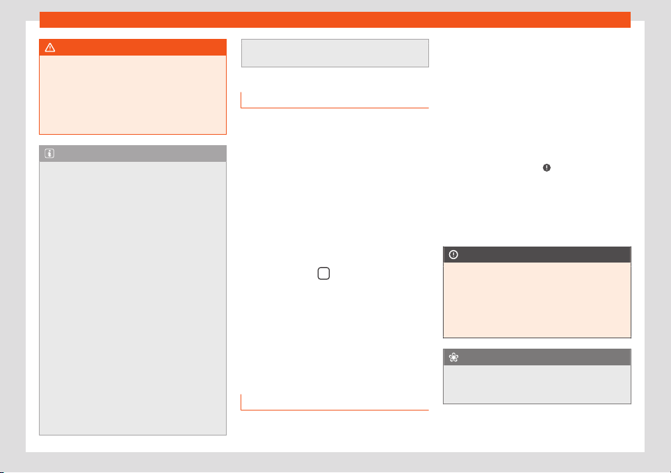
Instruments and warning/control lamps
WARNING
If messages are ignored, the vehicle may
stall in traffic and cause accidents and se-
vere injuries.
●
Never ignor
e the messages displayed.
●
Stop the vehicle at the next opportunity
and in a safe place.
Note
To avoid affecting the correct operation of
the system, take the following points int
o
consideration:
●
Regularly clean the area of vision of the
camera and keep it in a clean state, without
snow or ice.
●
Do not cover the field of vision of the
camera.
●
Always replace damaged or worn blades
when required to avoid lines on the cam-
era's field of vision.
●
Check that the windscreen is not dam-
aged in the area of the camera's field of vi-
sion.
●
The use of outdated maps on the naviga-
tion system may cause the system to show
traffic signs incorrectly.
●
In the waypoints mode of the navigation
system, the traffic sign detection system is
only partly available.
●
Failure to heed the control lamps and
corresponding text messages when they
light up may result in damage to the vehi-
cle.
Time
Setting the time on the infotainment sys-
tem
●
Press the infotainment butt
on.
●
Press the SETTINGS > Date and time
function button to adjust the time
›››
page 82.
Adjusting the time in the SEAT Digital
Cockpit
●
While in the Driving data menu, select
the Range function (infotainment button
>
View > Driving data > Range).
●
Press the button
on the multifunction
st
eering wheel until the Service menu is dis-
pl
ayed on the instrument panel displ
ay
›
›
›
page 69
.
●
Select the menu Time.
●
Adjust the correct time by turning the right
thumbwheel of the multifunction steering
wheel.
Revolution counter
The rev counter indicates the number of en-
gine r
e
v
olutions per minut
e
.
T
ogether with the gear
-change indicator, the
rev counter offers you the possibility of using
the engine of your vehicle at a suitable
speed.
The beginning of the red zone of the rev
counter indicates the maximum speed in any
gear after running-in and with the engine hot.
However, it is advisable to change up a gear
or move the selector lever to D (or lift your
foot off the accelerator) before the needle
reaches the red zone
›››
.
W
e r
ecommend that you av
oid high r
e
vs and
that you f
oll
ow the recommendations on the
gear-change indicator. Consult the addition-
al information in
›››
page 261, Selecting the
optimal gear.
CAUTION
●
To prevent damage to the engine, the r
ev
counter needle should only remain in the
red zone for a short period of time.
●
When the engine is cold, avoid high revs
and heavy acceleration and do not make
the engine work hard.
For the sake of the environment
Changing up a gear early will help you to
save fuel and minimise emissions and en-
gine noise.
75
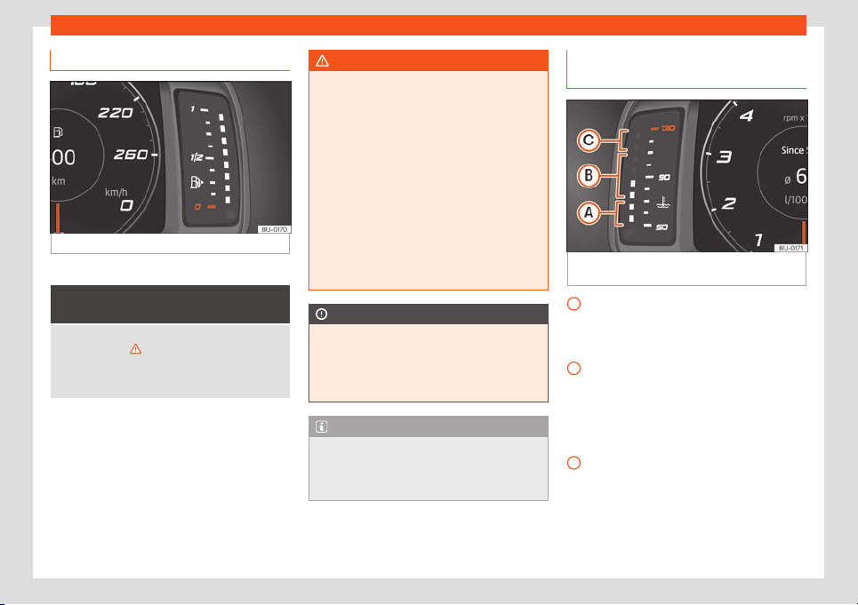
Operation
Fuel gauge
Fig. 62
Digital instrument panel: fuel gauge.
Control lamps
It lights up, and in addition, the
lower diode lights up in red
Fuel tank almost empty. The fuel r
eserve level has
been reached
›››
. Refuel as soon as you have the
opportunity.
When the fuel level is very low, the lower diode flash-
es red.
The display only works when the ignition is
s
wit
ched on.
The fuel r
ange is displ
ayed on the instrument
panel.
Y
ou can consult the t
ank capacit
y of your ve-
hicle in the
›››
page 389 section.
WARNING
When driving with low fuel, the vehicle may
stall in traffic and cause accidents and se-
vere injuries.
●
If the fuel tank le
vel is too low, fuel could
reach the engine irregularly, particularly
when driving up or down slopes.
●
The steering system and the driver assis-
tance systems and brakes do not work
when the engine is running irregularly or
switches off due to lack of fuel or an irregu-
lar supply thereof.
●
Always refuel when there is only one
quarter of fuel in tank to prevent the vehicle
to stop due to lack of fuel.
CAUTION
Never run the fuel tank completely dry. An
irregular fuel supply can cause misfiring
and unburnt fuel could enter the exhaust
system. The cat
alytic converter or the par-
ticulate filter may get damaged!
Note
The small arrow on the fuel gauge next to
the fuel pump symbol points out towards
the side of the vehicle with the fuel t
ank
flap.
Engine coolant temperature indica-
t
or
Fig. 63
Digital instrument panel: engine cool-
ant t
emper
at
ur
e indicat
or
.
Cool zone. The engine has not r
eached
oper
ating t
emper
at
ur
e yet. Av
oid high
speeds and stressing the engine if it has
not reached operating temperature.
Normal zone. At high outside tempera-
tures and when making the engine work
hard, the diodes may continue lighting up
and reach the upper zone. This is no
cause for concern, provided the control
lamp does not light up
Warning area. When the engine is work-
ing hard, especially at high outside tem-
peratures, the diodes may light up in the
warning area.
The coolant temperature gauge only works
when the ignition is switched on.
A
B
C
76
Instruments and warning/control lamps
Control and warning lamp
It lights up red
Do not carry on driving!
Engine coolant level too lo
w, coolant temperature too
high.
Flashes red
Fault in the engine coolant system.
●
Stop the vehicle, switch off the engine and
let it cool down.
●
Check the engine coolant level
›
››
page 355.
●
If the warning lamp does not s
witch off even
if the coolant level is correct, request assis-
tance from specialised personnel.
CAUTION
●
To ensure a long useful life for the engine,
av
oid high revs, driving at high speed and
making the engine work hard for approxi-
mately the first 15 minutes when the engine
is cold. The phase until the engine is warm
also depends on the outside temperature. If
necessary, use the engine oil temperature*
›››
page 69
›››
page 70 as a guide.
●
Additional lights and other accessories in
front of the air inlet reduce the cooling ef-
fect of the coolant. At high outside temper-
atures and high engine loads, there is a risk
of the engine overheating.
●
The front spoiler also ensures proper dis-
tribution of the cooling air when the vehicl
e
is moving. If the spoiler is damaged this can
reduce the cooling effect, which could
cause the engine to overheat. Seek spe-
cialist assistance.
Service intervals
The service interval indication appears on the
instrument panel display and the Infotain-
ment system.
There are diff
erent versions of instrument
panels and infotainment systems, so the ver-
sions and instructions on the screens may
vary.
SEAT distinguishes between services with en-
gine oil change (e.g. Oil change service) and
services without engine oil change (e.g. In-
spection).
In vehicles with Services established by
time or mileage, the service intervals are al-
ready pre-defined.
In vehicles with LongLife Service, the inter-
vals are determined individually. Thanks to
technological progress, maintenance work
has been greatly reduced. Because of the
technology used by SEAT, with this service
you only need to change the oil when the ve-
hicle so requires. To calculate this variation
(max. 2 years), the vehicle's conditions of use
and individual driving styles are considered.
The advance warning first appears 20 days
before the date established f
or the corre-
sponding service. The kilometres (miles) re-
maining until the next service are always
rounded up to the nearest 100 km (miles) and
the time is given in complete days. The cur-
rent service message cannot be viewed until
500 km after the last service. Prior to this, on-
ly lines are visible on the display.
Inspection reminder
If a service or an inspection has to be carried
out soon, a service reminder will be dis-
played when the ignition is switched on.
The figure displayed are the kilometres that
can still be travelled or the time until the next
service.
Service due
When the time for a service or an inspec-
tion comes, an audible warning will be emit-
ted when the ignition is switched on and the
fixed key symbol may appear on the in-
strument panel for a few seconds, along with
one of the following messages:
●
Service now!
●
Please have your vehicle inspec-
ted.
●
Oil change service due!
»
77
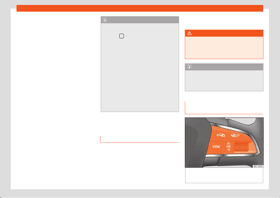
Operation
●
Oil change service and inspection
due!
Consult a service notification
With the ignition s
wit
ched on, the engine off
and the v
ehicl
e at a st
andstill, the curr
ent
service notification
can be read:
Check the date of the current service on the
infotainment system
●
Press the infotainment button .
●
Press the function button SETTINGS
›››
page 82.
●
Select the Service menu option to display
information about the services.
Resetting service interval display
If the service was not carried out by a SEAT
dealership, the display can be reset as fol-
lows:
●
The service interval display can only be re-
set through the Service menu
›››
page 69.
Do not restart the indicator between the
service intervals, otherwise the information
displayed will be incorrect.
If the oil change service is reset manually, the
service interval display changes to a fixed
service interval, also in vehicles with Flexible
oil change service.
Note
●
The service message disappears after a
few seconds, when the engine is started or
when the button is pressed on the multi-
function steering wheel.
●
In vehicles with the LongLife system in
which the batt
ery has been disconnected
for a long period of time, it is not possible to
calculate the date of the next service.
Therefore the service interval display may
not be correct. In this case, bear in mind the
maximum service intervals permitted
›››
page 373.
●
If you reset the display manually, the next
service interval will be indicated as in vehi-
cles with fixed service intervals. For this
reason we recommend that the service in-
terval display be reset by a SEAT author-
ised Dealer.
Using the instrument panel
Intr
oduction
With the ignition switched on, it is possible to
r
ead the diff
er
ent functions of the displ
ay by
scr
olling thr
ough the menus.
The multifunction displ
ay can only be con-
trolled from the buttons on the multi-function
steering wheel.
Some menu options can only be read when
the vehicle is at a standstill.
WARNING
Distracting the driver in any way can lead
to an accident and cause injuries.
●
Never use the menus on the instrument
panel display while the vehicl
e is in motion.
Note
After loading or changing the 12-volt bat-
tery, check the system settings. If the pow-
er supply is interrupted, the system settings
might be incorr
ect or deleted.
Operation using the multifunction
st
eering wheel
Fig. 64 Right side of the multifunction steering
wheel
: butt
ons t
o the menus and inf
ormation
displ
ays on the instrument panel
.
78
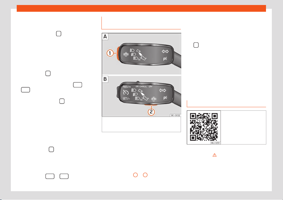
Instruments and warning/control lamps
As long as a priority 1
›
›
›
page 70
w
arning is
activ
e
, it will not be possible to access any
menu. Some warnings can be confirmed and
hidden with the button
of the multifunction
st
eering wheel
›
›
›
Fig. 64
.
Sel
ect a menu or an inf
ormative display
●
Switch the ignition on.
●
Customisation option: select a user.
●
If a message or vehicle symbol is displayed,
press the button
›
›
›
Fig. 64
; if necessary,
se
v
er
al times.
●
To change menus, use buttons
or
›
›
›
Fig. 64
.
●
T
o open the menu or the inf
ormation dis-
pl
ayed, press the button
›
›
›
Fig. 64
or w
ait
a f
e
w seconds until the menu or the informa-
tive display opens automatically.
Changing menu settings
●
In the menu displayed, turn the right thumb-
wheel of the multifunction steering wheel
›››
Fig. 64 until the desired option of the menu
is highlighted. The option appears framed.
●
Press the button
›
›
›
Fig. 64
t
o mak
e the
r
equired modifications. A mark indicates that
the system or function is activated.
Back to menu selection
Press the button
or
›
›
›
Fig. 64
.
Butt
on f
or the driv
er assistance
systems*
Fig. 65
On the turn signal and main beam lev-
er: butt
on f
or driv
er assist
ance syst
ems (de-
pending on v
ersions).
With the turn signal and main beam headlight
l
e
v
er butt
on, you can activ
at
e or deactiv
ate
the driver assistance systems displayed in the
Assistance systems menu .
Activate or deactivate a driver assistance
system
●
Press
›››
Fig. 65
1
or
2
briefly to open the
Driving aids menu.
●
Sel
ect the driv
er assist
ance syst
em and ac-
tiv
at
e or deactiv
ate it
›››
page 78. A mark in-
dicates that driver assistance system is
switched on.
●
Next, confirm the selection by pressing
the
button on the multi-function steering
wheel.
The driv
er assist
ance syst
ems can al
so be
s
wit
ched on and off in the inf
otainment sys-
tem, in the menu Vehicle settings
›››
page 82.
Control lamps
Control and warning lamps
Fig. 66 Related video
The control and warning lamps are indicators
of w
arnings
›
›
›
, faults or certain functions.
Some contr
ol and w
arning l
amps come on
when the ignition is s
wit
ched on, and s
wit
ch
off when the engine starts running, or while
driving.
»
79

Operation
Depending on the model, additional text
messages may be vie
w
ed on the instrument
panel displ
ay. These may be pur
ely inf
orma-
tiv
e or they may be advising of the need f
or
action
›››
page 64, Instrument panel.
Depending upon the equipment fitted in the
vehicle, instead of a warning lamp, some-
times a symbol may be displayed on the in-
strument panel.
When certain control and warning lamps are
lit, an audible warning is also heard.
Red warning lamps
Notification central lamp: additional infor-
mation on the instrument panel display
Parking brake on
›››
page 297.
Fault in the brak
e system
›
›
›
page 297
.
F
ault in the st
eering syst
em
›
›
›
page 262
.
Driv
er or passenger has not f
ast
ened seat
belt
›››
page 16.
Press the foot br
ake
›››
page 278.
AdBlue le
vel too low, OR fault in the SCR
system
›››
page 345.
Yellow warning lamps
Notification central lamp: additional infor-
mation on the instrument panel display
Front brake pads worn
››
›
page 297.
Fault in ESC or disconnection caused by
the system; OR ESC or ASR in operation
›››
page 302.
ASR manually deactivated; OR ESC in
Sport mode
›››
page 302.
Fault in the ABS
››
›
page 302.
Rear fog light s
witched on
›››
page 109.
Fault in the emission control syst
em
›››
page 347.
Pr
e-heating of the diesel engine; OR fault
in the management of the diesel engine
›››
page 347.
Fault in the petrol engine management
›
›
›
page 34
7
.
P
articul
ate filter blocked
›››
page 347.
Fault in the steering system
›››
page 262.
Tyre monitor system
›››
page 369.
Fuel tank almost empty
›››
page 76.
Adblue level low, OR fault in the SCR sys-
tem
›››
page 345.
Fault in airbag system and seat belt ten-
sioners
›››
page 25.
Front passenger front airbag is disa-
bled
›››
page 25.
The front passenger front airbag is activa-
ted
›››
page 25.
Lane assist w
arning (Lane Assist)
›››
page 286.
Error in the lane assist w
arning system
›››
page 286.
Fault in the lighting of the vehicl
e
›››
page 109.
Low engine oil l
evel
›››
page 353.
Fault in the gearbox
›
››
page 259.
Windscreen cleaning fluid t
oo low
›
›
›
page 1
18
.
Other warning lamps
Turn lights or emergency lights on
›››
page 109.
Trail
er turn signals
›››
page 109.
Auto Hold activ
ated
›››
page 301.
Press the foot br
ake
›
›
›
page 254
.
Cruise contr
ol (GRA)
›
›
›
page 268; OR
speed limited
›
››
page 270; OR Adaptive
cruise control (ACC)
›››
page 278.
Lane assist warning (Lane Assist)
›››
page 286.
Main beam on or flasher on
›
›
›
page 109
.
80

Instruments and warning/control lamps
Door(s), rear lid or bonnet open or not
properly closed
›››
page 67
.
Engine cooling fluid
›››
page 76.
Engine oil pressure
›
›
›
page 353
.
F
ault in the batt
ery
›
›
›
page 360
.
Main beam assist (Light Assist)
›
›
›
page 109.
Hill descent control (HDC)
››
›
page 261.
Service interval displ
ay
›
›
›
page 7
7
.
Mobil
e t
elephone is connected via Blue-
tooth
®
›››
page 233.
Mobile t
elephone battery charge status
›››
page 233.
Risk of freezing
›
››
page 67.
Start
-Stop system activated
›››
page 250.
Start-Stop system unavailable
›››
page 250.
Low consumption driving st
atus
›››
page 68.
WARNING
If the warning lamps and messages are ig-
nored, faults may occur in the vehicle, it
may stall in tr
affic, or accidents and seri-
ous injuries may occur.
●
Never ignore the warning lamps or text
messages.
●
Stop the vehicle safely as soon as possi-
ble.
●
A f
aulty vehicle represents a risk of acci-
dent for the driver and for other road users.
If necessary, switch on the hazard warning
lamps and put out the warning triangle to
advise other drivers.
●
Before opening the bonnet, switch off the
engine and allow it to cool.
●
In any vehicle, the engine compartment is
a hazardous area and could cause severe
injuries
›››
page 349.
81
Operation
Easy Connect system
Intr
oduction
The infotainment system brings together im-
portant vehicle functions and systems into a
single centr
al control unit, e.g. menu settings,
radio equipment and the navigation system.
General operating information
The following section contains all of the rele-
v
ant information for changing the settings in
the Vehicle Settings menu. General infor-
mation on the operation of the infotainment
system, as well as on the warning and safety
instructions that must be taken into account,
is found in
›››
page 165
WARNING
Any distraction may lead to an accident,
with the risk of injury. Operating the Easy
Connect system while driving could dis-
tract you from tr
affic.
Vehicle menu settings
Fig. 67 Easy Connect: Main menu. Fig. 68 Easy Connect: Vehicle Menu.
Open the Vehicle settings menu
●
Switch the ignition on.
●
If the Infotainment System is off, switch it on.
●
Press the Infotainment button and then
the Vehicle
›
›
›
Fig. 6
7
function butt
on.
●
OR:
Press the infotainment button to go
to the Vehicle
›››
Fig. 68 menu.
●
Press the SETTINGS function button to open
the Vehicle settings menu.
●
To select a function in the menu, press the
desired button.
82

Instruments and warning/control lamps
Menu Submenu Possible setting Description
ESC system –
Activating or deactivating the traction control system (ASR) or selecting the
Sport mode of the electronic stability control (ESC Sport)
››
›
page 302
Tyres
Tyre monitor system Tyre pressure storing (Calibration)
›››
page 369
Winter tyres
Activation and deactivation of the speed warning, adjusting the speed warning
value
›››
page 367
Vehicle lights
Light assistance
Dynamic Light Assist, Light Assist, motorw
ay function, turning-on time, headlamp
range adjustment, automatic lights when raining, one-touch signalling, travel
mode
.
›››
page 109
Vehicle interior lighting Brightness of instrument panel and controls
›››
page 117
Coming/Leaving home function Switch-on time of the “Coming home” and “Leaving home” functions
›
››
page 1
14
Driver assis-
tance
Adaptive Cruise Control (ACC) Activ
ation and deactiv
ation: def
ault dist
ance l
e
vel, driving profiles.
›››
page 277
Front Assist (ambient traffic
monitoring system)
Activation and deactivation: Front Assist, advance warning, distance warning dis-
play
›››
page 273
Lane Assist (lane departure
warning assistance)
Activation and deactivation of lane departure warning assistance, adaptive lane
guidance, activation and deactivation of steering wheel vibration
›››
page 286
Dynamic Road Sign Display
Display on the instrument panel, activation and deactivation of the speed warn-
ing
›››
page 72
Trailer detection
Trailer recognition (display of traffic signs for vehicles with trailer), use to calcu-
late the route, maximum speed for trailer
›››
page 74
Driver alert system Activation and deactivation
›››
page 71
Parking and ma-
noeuvring
ParkPilot
Automatic activation, front volume, front sound treble, rear volume, rear sound
treble, adjust Infotainment volume
›››
page 315,
›››
page 319
Manoeuvre braking Switching on and off
›››
page 318
Ambient lighting – Switching on and off, selecting brightness, colour, area or total
›››
page 117
»
83

Operation
Menu Submenu Possible setting Description
Mirrors and
windscreen wip-
ers
Rear view mirrors
Synchronous adjustment, lower the passenger side mirror while reversing (kerb
function), fold in after parking, exterior mirrors heating, dim when dark
›
››
page 121
Windscreen wipers
Activate and deactivate automatic wipers if raining, rear window wiping in re-
verse gear
›››
page 118
Opening and
closing
Electric windows
Convenience opening, aut
omatic closure in case of rain, automatic closure with
central locking
›››
page 105
Central locking
Door unlocking, audio confirmation “Easy Open”, “Easy Entry” access assis-
t
ance, automatic opening of the rear lid, interior monitoring
›
››
page 89
Instrument panel Multifunction display
Current consumption, average consumption, convenience consumers, ECO Ad-
vice, travelling time, distance trav
elled, average speed, digital speed display,
speed warning, oil temperature, coolant temperature, reset data “when setting
off”, reset data for “total calculation”, traffic signal detection
›››
page 69
Date and time – Time source, time, select time zone, time format, date, date format
›››
page 75
Units –
Distance, speed, temperature, volume, fuel consumption, GNC consumption,
el
ectric consumption, pr
essur
e
–
Service –
V
ehicl
e ID number
, dat
e of next SEAT service inspection, date of next oil change
service
›››
page 77
Factory settings
Restore all settings and data Restore all settings –
Restore settings/data sepa‐
rately
Lights, driver assistance, parking and manoeuvring, background lighting, rear
view mirrors and windscreen wipers, opening and closing, instrument panel
–
When the function button check box is activa-
t
ed
, the function is activ
e
.
Pr
essing the menu butt
on will always take
you to the last menu used.
Any changes made using the settings menus
are automatically saved on closing those
menus.
The actual number of menus available and
the name of the various options will depend
on the vehicle’s electronics and equipment.
84
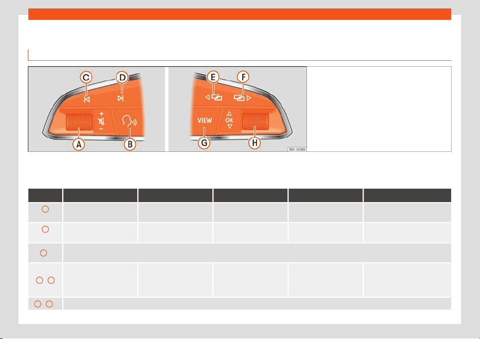
Instruments and warning/control lamps
Multifunction steering wheel*
Oper
ation of the audio
, t
el
ephone and navigation syst
em with v
oice contr
ol
Fig. 69 Controls on the steering wheel.
The steering wheel includes a multifunction
modul
e fr
om wher
e it is possibl
e t
o contr
ol
the audio
, telephone and radio/navigation
functions without needing to distract the driv-
er.
Button Radio Media (except AUX) AUX Telephone* Navigation*
A
Turn
Turn volume up/down. Turn volume up/down. Turn volume up/down. Turn volume up/down.
Turn announcement volume
up/down.
A
Press
Mute volume. Mute volume. Mute volume. Mute incoming call. Mute voice navigation.
B
a)
Enable/disable voice control
b)
.
This function can be used from any mode, except in the case of an active call.
C
/
D
Search for the previous/next
station
c)
.
Short press: Switch to the
pr
evious/next tr
ack.
Long press: Fast rewind/for-
ward
d)
.
No function
– No active call: Radio/Me-
dia functionality (except
AUX)
– Active call: no function
No function for the other modes
(navigation, assistants, vehicle
status, travel data).
E
/
F
a)
Change menu on instrument panel.
b)
»
85

Operation
Button Radio Media (except AUX) AUX Telephone* Navigation*
G
Short press
b)
: Change views Classic Info / Digit
al Maps / Semicircular dials
Long press
b)
: access the “Personalised Profiles” configuration view.
H
Turn
List of sources available
(audio/media).
List of sources available
(audio/media).
No function
– There is no active call: Re-
cent calls list.
– Active call: go to the call
options list (call in st
andby,
hang up, mute microphone,
private number, etc.).
If there is a map on the Digital
Scorecard: Zoom in-out (with and
without active route).
If ther
e is no map on the Digital
Panel: the map is transferred from
the infotainment System display
to the Digital Panel (with and
without active route).
H
Press
No function No function No function No function
Auto/Manual Zoom Zoom if the
map on the DigitScorecard.
a)
According to the vehicle's equipment package.
b)
This function can be used from any mode (audio, media, navigation, vehicle status, travel data).
c)
This action can be performed when you are listening to the radio; there is no need to be in audio-radio mode.
d)
These actions can be performed when you are listening to media; there is no need to be in audio-radio mode.
86
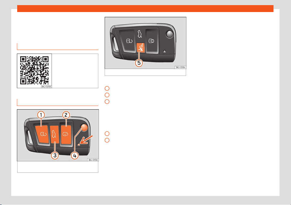
Opening and closing
Opening and closing
Set of v
ehicl
e k
eys
R
el
at
ed video
Fig. 70 Opening and
cl
osing
Vehicle key
Fig. 71
Assignment of buttons on the remote
contr
ol k
ey.
Fig. 72 Vehicle key with alarm button.
Key to the
›
›
›
Fig. 7
1
,
›
›
›
Fig. 72
Unlock the vehicle
Lock the vehicle
Unlock only the rear lid. Press the button
until all the turn signals on the vehicle
flash briefly. You have 2 minutes to open
the rear lid. Once this time has passed, it
will lock again. In addition, the lamp on
the key flashes.
Folding the key shaft in and out
Alarm button*. Only press in the event of
an emergency! When the alarm button is
pressed, the vehicle's sounds and the turn
signals light up for a short time. Press
again to disconnect.
With the vehicle key the vehicle may be
locked or unlocked remotely
›››
page 89.
The vehicle key includes an emitter and bat-
tery. The receiver is in the interior of the vehi-
1
2
3
4
5
cle. The range of the vehicle key with remote
contr
ol and ne
w batt
ery is se
v
er
al metr
es
around the vehicle.
If it is not possible to open or close the vehicle
using the remote control key, this should be
re-synchronised
›››
page 89 or the battery
changed
›››
page 88.
Different keys belonging to the vehicle may
be used.
Control lamp on the vehicle key
When a button on the vehicle key is pressed,
the control lamp flashes
›››
Fig. 71 (arrow)
once briefly, but if the button is held down for
a longer period the control lamp flashes sev-
eral times, such as in convenience opening.
If the vehicle key control lamp does not light
up when the button is pressed, replace the
key's battery
›››
page 88.
Spare key
To obtain a spare key and other vehicle keys,
the vehicle ID number is required.
Each new key contains a microchip which
must be coded with the data from the vehicle
electronic immobiliser. A vehicle key will not
work if it does not contain a microchip or the
microchip has not been encoded. This is also
true for keys which are specially cut for the
vehicle.
»
87
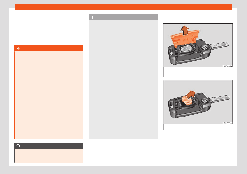
Operation
The vehicle keys or new spare keys can be
obt
ained fr
om a SEAT Official Service
, a spe-
cialised w
orkshop or an appr
o
v
ed key service
qualified to create this kind of key.
New keys or spare keys must be synchronised
before use
›››
page 89.
WARNING
●
Never leave children or disabl
ed persons
in the vehicle. In case of emergency, they
may not be able to leave the vehicle or
manage on their own.
●
An uncontrolled use of the key could start
the engine or activate any electric equip-
ment (e.g. electric windows), causing risk
of accident. The doors can be locked using
the remote control key. This could become
an obstacle for assistance in an emergen-
cy situation.
●
Never forget the keys inside the vehicle.
An unauthorised use of your vehicle could
result in injury, damage or theft. Therefore
always take the key with you when you
leave the vehicle.
●
Never remove the key from the ignition if
the vehicle is in motion. Otherwise, the
steering could suddenly block and it would
be impossible to steer the vehicle.
CAUTION
All of the vehicle keys contain electronic
components. Protect them from damage,
impacts and humidity.
Note
●
Only use the key button when you require
the corresponding function. Pushing the
button unnecessarily coul
d accidentally
unlock the vehicle or trigger the alarm. It is
also possible even when you are outside
the radius of action.
●
Key operation can be greatly influenced
by overlapping radio signals close to the
vehicle working in the same range of fre-
quencies, for example, radio transmitters or
mobile telephones.
●
Obstacles between the remote control
and the vehicle, bad weather conditions
and discharged batteries can considerably
reduce the range of the remote control.
●
If the buttons of the vehicle key are
pressed or one of the central locking but-
tons
›››
page 92 is pressed repeatedly in
short succession, the central locking brief-
ly disconnects as protection against over-
loading. The vehicle is then unlocked. Lock
it if necessary.
●
Spare remote control keys are available
at your Technical Service, where they must
be matched to the locking system.
●
Up to five remote control keys can be
used.
To change the battery
Fig. 73
Vehicle key: opening the battery com-
partment co
v
er
.
Fig. 74 Vehicle key: removing the battery.
SEAT recommends you ask a specialised
w
orkshop t
o r
epl
ace the batt
ery.
The batt
ery is l
ocated to the rear of the vehi-
cle key, under a cover.
88

Opening and closing
Changing the battery
●
Unfold the vehicle key blade
›
›
›
page 87
.
●
R
emo
v
e the cover from the back of the ve-
hicle key
›››
Fig. 73 in the direction of the ar-
row
›››
.
●
Extract the battery from the compartment
using a suit
abl
e thin ob
ject
›
›
›
Fig. 7
4.
●
Place the new battery in the compartment
as shown
›››
Fig. 74, pressing in the opposite
direction to that shown by the arrow
›››
.
●
Fit the cover as shown
›
›
›
Fig. 7
3
, pr
essing it
ont
o the vehicle key casing in the opposite di-
rection to that shown by the arrow until it
clicks into place.
CAUTION
●
If the battery is not changed correctly,
the vehicle key may be damaged.
●
Use of unsuitabl
e batteries may damage
the vehicle key. For this reason, always re-
place the dead battery with another of the
same voltage, size and specifications.
●
When fitting the battery, check that the
polarity is correct.
For the sake of the environment
Please dispose of your used batteries cor-
rectly and with respect for the environ-
ment.
Synchronize the vehicle key
If the button is pressed frequently outside
of the vehicle range
, it is possible that the ve-
hicle can no longer be locked or unlocked us-
ing the key. In this case, the key must be re-
synchronised as described below:
●
Unfold the vehicle key blade
›››
page 87.
●
If necessary, remove the cover from the
driver door lever
›››
page 99.
●
Press the button on the vehicle key. For
this, it must remain with the vehicle.
●
Open the vehicle within one minute using
the key blade. The key has been synchron-
ised.
●
If necessary, fit the cap.
Centr
al locking
Introduction
Central locking functions correctly when all
the doors and the r
ear lid ar
e corr
ectly shut. If
the driv
er door is open, the v
ehicl
e
cannot be
locked with the key.
If the vehicle has the Keyless Access locking
and ignition system, it may only be locked
with the ignition off and the driver's door
closed.
The battery of an unlocked vehicle parked for
a long period (e.g. in a private garage) may
run down and fail to start the motor.
WARNING
The incorrect use of the central locking
system may cause serious injuries.
●
The central locking system will lock all
doors. A vehicl
e locked from the inside can
prevent any non-authorised individual from
opening the doors and accessing the vehi-
cle. Nevertheless, in case of emergency or
accident, locked doors will complicate ac-
cess to the vehicle interior to help the pas-
sengers.
●
Never leave children or disabled people
alone in the vehicle. The central locking
button can be used to lock all the doors
from within. Therefore, passengers will be
locked inside the vehicle. Individuals locked
in the vehicle can be exposed to very high
or very low temperatures.
●
Depending on the time of the year, tem-
peratures inside a locked and closed vehi-
cle can be extremely high or extremely low
resulting in serious injuries and illness or
even death, particularly for young children.
●
Never leave individuals locked in a closed
and locked vehicle. In case of emergency,
they may not be able to exit the vehicle by
themselves or get help.
89

Operation
Description
Central locking allows all doors, the rear lid
and the tank flap to be unlocked centrally:
●
Fr
om outside, using the vehicle key
›››
page 91.
●
From outside with the Keyless Access
›››
page 92 system,
●
From inside, by pushing the central locking
button
›››
page 92.
Various functions are available to improve the
vehicle safety:
●
Security system “Safe”
›››
page 95
●
Self-locking system t
o prevent involuntary
unlocking
●
Selective unlocking system
●
Automatic speed dependent locking and
unlocking system (Auto Lock)
●
Emergency unlocking system
Self-locking system to prevent involuntary
unlocking
It is an anti-theft system and prevents the un-
intentional unlocking of the vehicle. If the ve-
hicle is unlocked and none of the doors (in-
cluding the boot) are opened within 30 sec-
onds, it re-locks automatically.
Unlocking one side of the vehicle only
When you lock the vehicle with the key, the
doors and the rear lid are locked. When you
open the door, you can either unlock only the
driver door, or all the vehicle doors. To select
the required option, use Easy Connect*
›››
page 90.
Automatic locking (Auto Lock)*
The Auto Lock function locks the doors and
the rear lid when the vehicle exceeds a speed
of about 15 km/h (9 mph).
The vehicle is unlocked again when the igni-
tion key is removed. Alternatively, the vehicle
can also be unlocked via the central locking
switch or by pulling one of the inside door
handles.
In the event of an accident in which the air-
bags inflate, the doors will be automatically
unlocked to facilitate access and assistance.
Turn signals
The turn signals will flash twice when the ve-
hicle is unlocked and once when the vehicle
is locked.
If it does not flash, this indicates that one of
the doors, the rear lid or the bonnet is not
closed correctly.
Accidental lock-out
The central locking system prevents you from
being locked out of the vehicle in the follow-
ing situations:
●
If the driver door is open, the vehicle cannot
be locked with the central locking switch
›››
page 92.
Lock the vehicle with the remote control key,
when all the doors and the rear lid have been
closed. This prevents the accidental locking
of the vehicle.
Note
●
Never leave any valuable it
ems in the ve-
hicle unattended. Even a locked vehicle is
not a safe.
●
If the LED on the driver door sill lights up
for about 30 seconds when the vehicle is
locked, the central locking system or anti-
theft alarm* is not working properly. You
should have the fault repaired at a SEAT
Official Service or specialised workshop.
●
The vehicle interior monitoring of the an-
ti-theft alarm* system will only function as
intended if the windows and the sunroof*
are closed.
Central locking settings
Central locking settings can be changed in
the Easy Connect* syst
em.
90
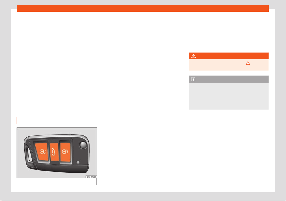
Opening and closing
Unlocking doors
●
Select: key > SETTINGS > Opening
and closing > Central locking > Un-
locking the doors.
Y
ou can choose t
o unl
ock
all the doors or
only the
driver door when you unl
ock the
v
ehicle. In all the options, the fuel tank flap is
also unlocked.
With the Driver setting, when you press the
button on the remote control key once, only
the driver door is unlocked. If that button is
pressed twice, the rest of the doors and the
rear lid will be unlocked.
If the button is pressed, all the vehicle
doors are locked. At the same time, a confir-
mation signal* is heard.
Unlock and lock from the outside
Fig. 75
Remote control key: buttons.
●
L
ock: pr
ess the
›
›
›
Fig. 75 button.
●
Locking the vehicle without the “Safe” se-
curity system: push the button again and
hold for 2 seconds.
●
Unlock: press the button.
●
Unlocking the rear lid: hold down the
button for at least 1 second.
The vehicle will be locked again automatical-
ly if you do not open one of the doors or the
rear lid within 30 seconds after unlocking the
car. This function prevents the vehicle from
remaining unlocked if the unlocking button is
pressed by mistake. This does not apply if you
press the button for at least one second.
Selective unlocking system
The selective unlocking system allows you to
only unlock the driver door and the fuel tank
flap. All other doors and the rear lid remain
locked.
Unlocking the driver's door and tank flap:
●
Press (once) the button on the remote
control key or turn the key once in the open-
ing direction.
Unlocking all the doors, the rear lid and the
tank flap simultaneously:
●
Within 5 seconds, press (twice) the but-
ton on the remote control key, or turn the key
twice within 5 seconds in the opening direc-
tion.
The Safe* security system and the anti-theft
alarm* deactivate immediately when only
the driver door is opened.
In vehicles with Easy Connect*, you can pro-
gramme the security central locking system
directly
›››
page 90.
WARNING
Observe the safety warnings
›››
in Lock-
ing system “Safe” on page 96.
Note
●
Do not use the remote control key until
the vehicle is visibl
e.
●
Other functions of the remote control key
›››
page 105, Convenience open/close
function.
91
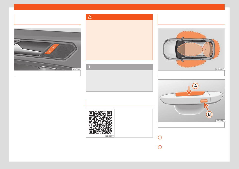
Operation
Unlocking and locking from the in-
side
Fig. 76
Driver's door: central locking switch.
●
Lock: press the
›
›
›
Fig. 76
butt
on.
●
Unl
ock: pr
ess the
›››
Fig. 76 button.
Please note the following when using the
central locking switch to lock your vehicle:
●
It is not possible to open the doors or the
rear lid from the outside (for safety reasons,
e.g. when stopped at traffic lights).
●
The LED in the central locking switch lights
up when all the doors are closed and locked.
●
You can open the doors individually from
the inside by pulling the inside door handle.
●
In the event of an accident in which the air-
bags inflate, doors locked from the inside will
be automatically unlocked to facilitate ac-
cess and assistance.
WARNING
●
The central locking switch also works
with the ignition s
witched off, except when
the “safe” system is activated.
●
The central locking switch does not oper-
ate if the vehicle is locked from the outside
and the security system is switched on.
●
Locked doors could delay assistance in
an emergency. Do not leave anyone, espe-
cially children, in the vehicle.
Note
Your vehicle will lock automatically when it
reaches a speed of about 15 km/h (9 mph)
(Auto Lock)
›››
page 90
. You can unlock the
vehicle again using the button on the
central locking switch.
Related video Keyless Access
Fig. 77 Convenience
Unlock and lock the vehicle with
K
eyl
ess Access*
Fig. 78
Keyless Access: proximity zones.
Fig. 79 Door handle: sensor surfaces
›››
Fig. 7
9
Unl
ocking sensor surf
ace on the inside of
the door handl
e
.
L
ocking sensor surf
ace on the outside of
the door handle.
A
B
92

Opening and closing
Depending on the equipment, the vehicle
may hav
e the K
eyl
ess Access syst
em.
K
eyl
ess Access is a k
ey-free locking and igni-
tion system to unlock and lock the vehicle
without actively using its key. To do this, all
that is required is to have a valid vehicle key in
the detection area where you are attempting
to access the vehicle
›››
Fig. 78 and to touch
one of the sensor surfaces on the door han-
dles
›››
Fig. 79 or operate the softtouch/han-
dle on the rear lid
›››
page 100
›››
.
The v
ehicl
e can be unl
ock
ed and l
ock
ed via
the fr
ont doors only. When doing so, the re-
mote control key must be no further than ap-
prox. 1.5 m away from the door handle.
It does not matter where you carry the key,
e.g. in your jacket pocket.
Once the doors have been locked, they can-
not be opened again immediately. This will
enable you to check that the doors are prop-
erly closed.
If you wish you may unlock only the corre-
sponding door or the entire vehicle. The nec-
essary adjustments can be made in vehicles
with a driver information system
›››
page 82
›››
page 68.
General information
If a valid key is in the proximity of the car,
›››
Fig. 78 the Keyless Access locking and
starting system gives the key entry as soon as
one of the sensor surfaces on the door han-
dles is touched or the softtouch/handle on
the rear lid is operated.
The following features are then available
without having to use the vehicle key actively:
●
Keyless Entry: unlocking the vehicle using
the handles of the front doors or the soft-
touch/handle on the rear lid.
●
Keyless Exit: locking the vehicle using the
sensor of the driver or passenger door han-
dle.
●
Easy Open: opening the rear lid moving one
foot below the rear bumper
›››
page 103.
●
Press & Drive: keyless starting of the engine
with the starter button
›››
page 246.
The central locking and locking systems op-
erate in the same way as a normal locking
and unlocking system. Only the controls
change.
Unlocking the vehicle is confirmed with a
double flash of the indicator lights; locking by
a single flash.
If the vehicle is locked and then all doors and
the rear lid are closed leaving the last key
used inside the vehicle and none outside, the
vehicle will not lock immediately. All the ve-
hicle's indicator lights will flash four times.
The vehicle will lock after a few seconds if
you do not open any door or the rear lid.
The vehicle will lock again after a few sec-
onds if you unlock the vehicle but fail to open
any door or boot hatch.
Unlocking and opening the doors
(Keyless-Entry)
●
Grip one of the front door handles. When
you do this, you touch the sensor surface
›››
Fig. 79
A
(arrow) of the handle and the
v
ehicl
e unl
ocks.
●
Open the door
.
On v
ehicl
es with sel
ective opening or info-
tainment system configuration, pulling the
door handle twice will unlock all doors.
In vehicles without the “Safe” security sys-
tem: closing and locking the doors
(Keyless-Exit)
●
Switch the ignition off.
●
Close the driver's door.
●
Touch (once) the locking sensor surface
›››
Fig. 79
B
(arrow) on one of the front door
handl
es. The door that is used must be
cl
osed.
In v
ehicl
es with the “Saf
e” securit
y sys-
t
em: closing and locking the doors
(Keyless-Exit)
●
Switch the ignition off.
●
Close the driver's door.
»
93
Operation
●
T
ouch (
once
) the sensor surf
ace
›
›
›
Fig. 79
B
(arrow) on one of the front door handles.
The v
ehicl
e l
ocks with the “Saf
e” securit
y sys-
t
em
›
››
page 95. The door that is used must
be closed.
●
Touch (twice) the sensor surface
›››
Fig. 79
B
(arrow) of one of the front door handles to
l
ock the v
ehicl
e without activ
ating the
“Saf
el
ock” securit
y system
›››
page 95.
Unlocking and locking the boot hatch
When the vehicle is locked, the rear lid auto-
matically unlocks on opening if there is a val-
id vehicle key in the proximity
›››
Fig. 78.
Open or close the rear lid normally.
After closing, the hatch locks automatically. If
the complete vehicle is unlocked, the rear lid
will not lock automatically after closing it.
What happens when locking the vehicle
with a second key
If there is a vehicle key inside the vehicle and
it is locked from the outside with a second ve-
hicle key, the key inside the vehicle is blocked
for engine ignition
›››
page 246. In order to
enable engine ignition, press the button on
the key inside the vehicle.
Automatically disabling sensors
If the vehicle is not locked or unlocked for a
long period of time, the proximity sensors on
the passenger doors are automatically disa-
bled.
If one of the sensor surfaces on the door han-
dles is often activated in an unusual manner
with the vehicle locked (e.g. by the branches
of a bush rubbing against it), all proximity
sensors are disabled for a certain period of
time.
Sensors will again be enabled:
●
After a time.
●
OR: if the vehicle is unlocked with the but-
ton on the key.
●
OR: if the boot is opened.
●
OR: if the vehicle is unlocked manually with
the key.
Keyless Access temporary disconnection
function*
You can deactivate the vehicle's Keyless
Access unlocking for one locking and unlock-
ing cycle.
●
Move the gear lever to position P (if the ve-
hicle has automatic gearbox), since other-
wise the vehicle cannot be locked.
●
Close the door.
●
Push the central locking button on the re-
mote control and touch the locking sensor
surface of the driver door handle
›››
Fig. 79
B
within the following 5 seconds.
Do not gr
asp the door handl
e; otherwise the
v
ehicl
e will not unl
ock
. Deactiv
ation is also
possible if the vehicle is locked through the
driver’s door lock.
●
To check that the function has been deacti-
vated, wait at least 10 seconds, grip and pull
on the door handle. The door should not
open.
The next time the door can only be unlocked
via the remote control or the lock cylinder.
The next time the door is locked/unlocked,
Keyless Access will be active again.
Convenience functions
To close all the electric windows and the sun-
roof using the comfort function, keep a fin-
ger for a few seconds on the locking sensor
surface
›››
Fig. 79
B
(arrow) of the door han-
dl
e until the windo
ws and r
oof hav
e cl
osed.
Ho
w the
doors open when touching the sen-
sor surface on the door handle will depend
on the settings that have been activated in
the infotainment system, using the button
> SETTINGS > Opening and closing.
CAUTION
The sensor surfaces on the door handles
could engage if hit with a water jet or high
pressure steam if ther
e is a valid vehicle
key in the proximity. If at least one of the
electric windows is open and the sensor
surface
›››
Fig. 79
B
(arrow) on one of the
94
Opening and closing
handles is activated continuously, all win-
dows will close.
Note
●
If the v
ehicle battery has little or no
charge, or the v
ehicle key battery is almost
or entirely out of charge, you will probably
not be able to lock or unlock the vehicle
with the Keyless Access system. The vehi-
cle can be unlocked or locked manually
›››
page 99.
●
To control the proper locking of the vehi-
cle, the release function is disabled for ap-
prox. 2 seconds.
●
If the message Keyless access system
faulty is displayed on the screen of the
dash panel, abnormalities may occur in the
operation of the Keyless Access system.
Contact a specialised workshop. SEAT rec-
ommends visiting a SEAT dealership for
this.
●
Depending on the function set on the in-
fotainment system for the mirrors, the exte-
rior mirrors will unfold and the surround
lighting will come on when unlocking the
vehicle using the sensor surface on the
driver and passenger door handles
›››
page 121.
●
If there is no valid key inside the vehicle
or the system fails to detect one, a warning
will display on the dash panel screen. This
could happen if any other radio frequency
signal interferes with the key signal (e.g.
from a mobil
e device accessory) or if the
key is covered by another object (e.g. an
aluminium case).
●
If the sensors are very dirty, e.g. have a
layer of salt, the correct functioning of the
sensors on the door handles may be affec-
ted. In this case, clean the vehicle.
●
If the vehicle is equipped with an auto-
matic gearbox, it may only be locked in the
gear stick is in position P.
●
To improve the safety of your vehicle, the
remote control of the system is equipped
with a position sensor. If this remote control
does not detect movement for a certain
length of time, the system will conclude
that the vehicle cannot be opened (e.g. on
a night table) so it will be disabled.
Locking system “Safe”
1)
When the vehicle is locked, the “Safe” securi-
t
y syst
em puts the door handl
es out of oper
a-
tion and mak
es it difficult f
or unauthoriz
ed
people to enter. The doors cannot be opened
from inside
›››
.
Depending on the v
ehicl
e
, when s
wit
ching the
ignition off
, a w
arning may be displayed on
the control panel screen stating that the
“Safe” security system is activated.
Lock the vehicle and activate the “Safe”
security system.
●
Press the locking button once on the ve-
hicle key.
Lock the vehicle without activating the
“Safe” system.
●
Press the locking button on the vehicle
key twice.
●
On vehicles with the Keyless Access locking
and ignition system: touch the sensor surface
on the outside part of the door handle twice.
When the “Safe” security system is disa-
bled, the following needs to be taken into
account:
●
The vehicle can be opened and unlocked
from the inside using an inside door handle.
●
The anti-theft alarm is activated.
●
The vehicle interior monitoring system and
the anti-tow system are disabled.
“Safe” status
The flashing frequency of the diode in the
door sill immediately confirms the process.
Initially, the diode flashes in a fast sequence
»
1)
Available depending on market and version.
95
Operation
for a brief period, then it stops for approxi-
mat
ely 30 seconds and, l
astly continues
fl
ashing sl
o
wly.
WARNING
Do not leave anyone (especially children)
in the vehicle if it is locked from the outside
and the “Safe” securit
y system* is activa-
ted, as the doors and windows cannot then
be opened from the inside. Locked doors
could delay assistance in an emergency.
Anti-theft alarm system*
Description
The anti-theft alarm makes it more difficult to
br
eak int
o the v
ehicl
e or st
eal it. The syst
em
will initiat
e acoustic and optical warning sig-
nals when your vehicle is tried to be forced.
The anti-theft alarm is automatically turned
on when the vehicle is locked with the key.
The system is immediately activated and the
turn signal light located on the driver door will
flash along with the turn signals, indicating
that the alarm and the locking security sys-
tem (double lock) have been turned on.
If any of the doors or the bonnet are open,
they will not be included in the protection
zones of the vehicle when the alarm is con-
nected. If the door or the bonnet are subse-
quently closed, they will be automatically in-
cluded in the protection areas of the vehicle
and the turn signals will flash accordingly
when the doors close.
●
The turn signal light will flash twice on
opening and deactivating the alarm.
●
The turn signal light will flash once on clos-
ing and activating the alarm.
When does the system trigger an alarm?
The anti-theft alarm siren will be triggered for
about 30 seconds alongside a sound and
optical (flashing) warning signals and will be
repeated about ten times when the vehicle is
locked and the following unauthorised ac-
tions are attempted:
●
Opening a door that is mechanically un-
locked using the vehicle key without switching
on the ignition in the next 15 seconds (in cer-
tain markets, such as the Netherlands, there is
no 15 second waiting time and the alarm is
activated immediately on opening the door).
●
A door is opened.
●
Opening the bonnet.
●
The rear lid is opened.
●
When the ignition is switched on with a non-
authorised key.
●
Undue manipulation of the alarm.
●
Disconnection of the vehicle battery.
●
Movement inside the vehicle (in vehicles
with interior monitoring
›››
page 97).
●
When the vehicle is towed (in vehicles with
anti-tow system
›››
page 97).
●
When the vehicle is raised (in vehicles with
anti-tow system
›››
page 97).
●
When the vehicle is transported on a ferry
or by rail (vehicles with an anti-tow system or
vehicle interior monitoring
›››
page 97).
●
When a trailer connected to the anti-theft
alarm system is disconnected.
How to turn OFF the alarm
●
Unlock the vehicle with the unlock button
of the key.
●
OR: turn the ignition on with a valid key.
If the driver’s door is unlocked mechanically
using the key, the key must be inserted into
the ignition, and the ignition must be turned
on within 15 seconds of opening the door.
Otherwise, the alarm will trigger for 30 sec.
and the ignition will be blocked.
CAUTION
If the anti-theft security system is switched
off, the vehicle interior monitoring and the
to
w-away protection are automatically
disconnected.
96

Opening and closing
Note
●
After 28 days, the indicator light will be
switched off to pre
vent the battery from ex-
hausting if the vehicle has been left parked
for a long period of time. The alarm system
remains activated.
●
If, after the audible warning goes off, an-
other monitored area is accessed (e.g. the
rear lid is opened after a door has been
opened), the alarm is triggered again.
●
The anti-theft alarm is not activated
when the vehicle is locked from within using
the central locking button .
●
If the driver door is unlocked mechanical-
ly with the key, only the driver door is un-
locked, the rest of the doors remain locked.
Only when the ignition has been turned on
will the other doors be available - but not
unlocked - and the central locking button
will be activated.
●
If the vehicle battery is run down or flat
then the anti-theft alarm will not operate
correctly.
●
Vehicle monitoring remains active even if
the battery is disconnected or not working
for any reason.
●
The alarm is triggered immediately if one
of the battery cables is disconnected while
the alarm system is active.
Interior monitoring and the anti-
t
o
w syst
em*
It is a monitoring or control function incorpo-
rated in the anti-theft alarm* which detects
unauthorised vehicle entry by means of ultr
a-
sound.
The vehicle interior monitoring and anti-tow
sensor (tilt sensor) are automatically switch-
ed on when the anti-theft alarm is switched
on. In order to activate it, all the doors and
the rear lid must be closed.
If the “Safe” security system*
›››
page 95 is
switched off, the vehicle interior monitoring
and the tow-away protection are automati-
cally disconnected.
Activation
●
It is automatically switched on when the
anti-theft alarm is activated.
Deactivation
●
Open the vehicle with the k
ey, either me-
chanically or by pressing the button on the
remote control. The time period from when
the door is opened until the key is inserted in
the contact should not exceed 15 seconds,
otherwise the alarm will be triggered.
●
Press the button on the remote control
twice. The volumetric sensor and tilt sensors
will be deactivated. The alarm system re-
mains activated.
The vehicle interior monitoring and the anti-
tow system are automatically switched on
again next time the vehicle is locked.
If you wish to switch off the vehicle interior
monitoring and the anti-tow system, it must
be done each time that the vehicle is locked;
if not, they will be automatically switched on.
The vehicle interior monitoring and the anti-
tow system should be switched off if animals
are left inside the locked vehicle (otherwise,
their movements will trigger the alarm) or
when, for example, the vehicle is transported
or has to be towed with only one axle on the
ground.
Deactivation through the infotainment
system
●
Turn off the ignition and select: key >
SETTINGS > Opening and closing> Cen-
tral locking > Interior monitoring.
●
When the vehicle is locked now, the vehicle
interior monitoring and the tow-away protec-
tion are switched off until the next time the
door is opened.
False alarms
Interior monitoring will only operate correctly
if the vehicle is completely closed. Please ob-
serve related legal requirements.
»
97
Operation
The following cases may cause a false
al
arm:
●
Open windo
ws (partially or fully).
●
P
anor
amic/tilting sunr
oof open (partially or
compl
et
ely).
●
Movement of objects inside the vehicle,
such as loose papers, items hanging from the
rear vision mirror (air fresheners), etc.
Note
●
If the vehicle is relocked and the alarm is
activ
ated without the volumetric sensor
function, relocking will activate the alarm
with all its functions, except the volumetric
sensor. This function is reactivated when
the alarm is switched on again, unless it is
deliberately switched off.
●
If the alarm has been triggered by the
volumetric sensor, this will be indicated by
a flashing of the warning lamp on the driver
door when the vehicle is opened. The flash
is different to the flash indicating the alarm
is activated.
●
The vibration of a mobile phone left in-
side the vehicle may cause the vehicle in-
terior monitoring alarm to trigger, as both
sensors react to movements and shakes in-
side the vehicle.
●
If on activating the alarm, any door or the
rear lid is open, only the alarm will be acti-
vated. The vehicle interior monitoring and
the anti-tow system will only be activated
once all the doors are closed (including the
rear lid).
Doors
Introduction
The doors and rear lid can be locked man-
ually and partially opened, for example if the
key or the central l
ocking is damaged.
WARNING
Opening and closing doors carelessly can
cause serious injury.
●
If the vehicle is locked from outside, the
doors and windows cannot be opened from
the inside.
●
Never leav
e children or disabled people
alone in the car. They could be trapped in
the car in an emergency and will not be
able to get themselves to safety.
●
Depending on the time of the year, tem-
peratures inside a locked and closed vehi-
cle can be extremely high or extremely low
resulting in serious injuries and illness or
even death, particularly for young children.
WARNING
Getting in the way of the doors and the rear
lid is dangerous and can lead to serious in-
jury.
●
Open and close the doors and the rear lid
only when there is nobody in the way.
CAUTION
When opening and closing in an emergen-
cy, car
efully disassemble components and
then reassemble them carefully to av
oid
damage to the vehicle.
98
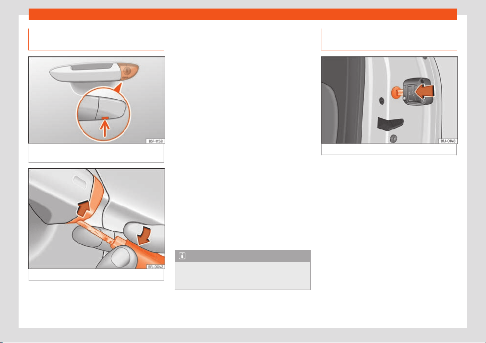
Opening and closing
Emergency unlocking or locking of
the driv
er
’
s door
Fig. 80
Driver door handle: Concealed lock
cylinder
.
Fig. 81
Driver door handle: lever the cover off
If the central locking system should fail to op-
er
at
e
, the driv
er door can still be l
ock
ed and
unl
ocked by turning the key in the lock.
As a general rule, when the driver door is
locked manually all other doors are locked.
When it is unlocked manually, only the driver
door opens. Please observe the instructions
relating to the anti-theft alarm system
›››
page 96.
●
Unfold the vehicle key blade
›››
page 87.
●
Insert the key shaft into the lower opening in
the cover on the driver door handle
›››
Fig. 81
then remove the cover upwards.
●
Insert the key blade into the lock cylinder to
unlock or lock the vehicle.
Special characteristics
●
The anti-theft alarm will remain active
when vehicles are unlocked. However, the
alarm will not be triggered
›››
page 96.
●
After the driver door is opened, you have 15
seconds to switch on the ignition. Once this
time has elapsed, the alarm is triggered.
●
Switch the ignition on. The electronic immo-
bilizer recognises a valid vehicle key and de-
activates the anti-theft alarm system.
Note
The anti-theft alarm is not activated when
the vehicle is locked manually using the
key shaft
››
›
page 89.
Emergency lock of doors without
l
ock cylinders
Fig. 82
Locking the door manually.
If the central locking system should fail to
w
ork at any time
, doors with no l
ock cylinder
will hav
e t
o be l
ock
ed separately.
The emergency lock is located on the front of
the front passenger's door and the rear
doors. It can only be seen if the door is open.
●
Insert the key in the inside slot and turn it to
the right as far as it will go (if the door is on
the right side) or to the left (if the door is on
the left side).
Once the door has been closed it can no lon-
ger be opened from the outside. Pull the inte-
rior door handle once to unlock and open the
door.
99
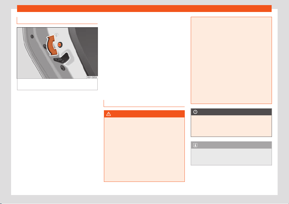
Operation
Childproof locks
Fig. 83
Childproof lock on the left hand side
door
.
The childproof lock prevents the rear doors
fr
om being opened fr
om the inside
. This sys-
t
em pr
e
v
ents minors from opening a door ac-
cidentally while the vehicle is running.
This function is independent of the vehicle
electronic opening and locking systems. It
only affects rear doors. It can only be activa-
ted and deactivated manually, as described
below:
Activating the childproof lock
–
Unlock the vehicle and open the door in
which you wish to activate the childproof
lock.
–
With the door open, rotate the groove in the
door using the ignition key, clockwise for
the left hand side doors
›››
Fig. 83 and anti-
clockwise for the right hand side doors.
Deactivating the childproof lock
–
Unlock the vehicle and open the door
whose childproof lock you want to deacti-
vate.
–
With the door open, rotate the groove in the
door using the ignition key, anti-clockwise
for the left hand side doors
›››
Fig. 83 and
clockwise for the right hand side doors.
Once the childproof lock is activated, the
door can only be opened from the outside.
Rear lid
Introduction
WARNING
Careless and unsuitable locking, opening
and closing of the rear lid can cause acci-
dents and serious injury.
●
The rear lid must not be opened when the
reverse or r
ear fog lights are lit. This may
damage the tail lights.
●
Do not close the rear lid by pushing it
down with your hand on the rear window.
The glass could smash. Risk of injury!
●
Ensure the rear lid is locked after closing
it. If not, it may open unexpectedly while
driving.
●
Closing the rear lid without observing
and ensuring it is clear could cause serious
injury to you and to thir
d parties. Make sure
that no one is in the path of the rear lid.
●
Never drive with the rear lid open or half-
closed, exhaust gases may penetrate into
the interior of the vehicle. Danger of poi-
soning!
●
Never leave the vehicle unattended or al-
low children to play inside or next to it, es-
pecially if the rear lid is open. Children
could enter the luggage compartment,
close the rear lid and become trapped. A
locked vehicle can reach extremely high
and low temperatures, depending on the
time of year, thus causing serious injuries,
illness or even death.
CAUTION
Before opening or closing the rear lid, make
sure that there is enough space to open or
close it, e.g. when pulling a trail
er or in a
garage.
Note
Before closing the rear lid, make sure that
the key has not been left inside the luggage
compartment.
100
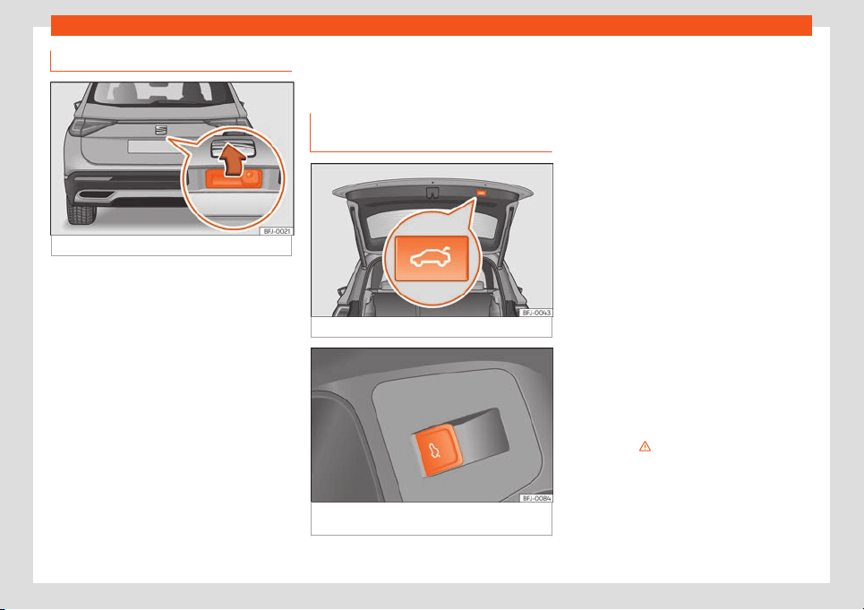
Opening and closing
Opening and closing the rear lid
Fig. 84
Rear lid: handle
The rear lid opening system operates electri-
cally. It is activ
at
ed by e
x
erting slight pr
essur
e
on the handl
e
›››
Fig. 84.
To lock or unlock the rear lid, press the or
buttons of the vehicle key.
A warning appears on the instrument panel
display if the rear lid is open or not properly
closed.* An audible warning is also given if it
is opened while the vehicle is moving faster
than 6 km/h (4 mph)*.
Opening and closing
●
To open: place slight pressure on the han-
dle. The rear lid opens automatically.
●
To close: hold one of the handles on the in-
ner trim and close it by moving it downwards,
or press the button on the rear lid*
›››
Fig. 85.
If the doors are locked, the rear lid is also
locked.
Rear lid with electric opening and
closing*
Fig. 85
Rear lid: button to close the rear lid.
Fig. 86
On the driver’s door: button to open
and cl
ose the r
ear lid.
Opening the rear lid
●
Unlock the vehicle
›
›
›
page 89
and briefly
pr
ess the handl
e of the r
ear lid. On vehicles
with Keyless Access you can directly press
the handle of the rear lid. The rear lid is un-
locked if an authorised key is recognised in
the proximity of the vehicle.
●
OR: depending on the features, pull the
button on the driver door upwards
›››
Fig. 86.
The button also works when the ignition is
switched off.
●
OR: press and hold the button of the ve-
hicle key for approx. 1 second. If the vehicle is
locked, only the rear lid is unlocked (the doors
remain locked).
●
OR: on vehicles with Keyless Access and
sensor-controlled opening you can open the
rear lid by moving one foot in the area of the
sensors located below the rear bumper (Easy
Open
›››
page 103). The rear lid will be auto-
matically opened.
Closing the rear lid
●
Briefly press the button on the rear lid
›››
Fig. 85
›››
in Introduction on page 100.
●
OR: depending on the f
eat
ur
es, pull the
butt
on on the driv
er door up
wards
›››
Fig. 86.
●
OR: on vehicles with Keyless Access, press
and hold the vehicle key button until the
rear lid is closed, or move one foot into the
area of the sensors located below the rear
bumper (Easy Open)
›››
page 103. The key of
»
101

Operation
the vehicle must not be further away than 1.5
m fr
om the boot or inside the v
ehicl
e
.
●
OR:
manually mo
v
e the rear lid in the direc-
tion of closing until it closes automatically.
●
The rear lid goes down automatically to the
final position and also closes automatically
›››
in Introduction on page 100.
Int
errupting opening or cl
osing
Aft
er beginning t
o open or cl
ose the r
ear lid,
the action can be halt
ed by pressing one of
the buttons.
Continue opening or closing the rear lid by
hand. To do this, some force will have to be
used.
If you press one of the buttons again, the
rear lid will move again in the original direc-
tion.
If the rear lid is met with resistance or an ob-
stacle during the automatic opening or clos-
ing, opening or closing will be interrupted im-
mediately. For the closing process, the rear
lid opens again slightly.
●
Check why it has not been possible to open
or close the rear lid.
●
Try to open or close the rear lid again.
●
If necessary, the rear lid can be opened or
closed by hand using reasonable force.
Restrictions if the vehicle has a third row of
seats
If the vehicle is fitted with a third row of seats,
it will not be possible to close the tailgate with
the button, on the driver’s door
›››
Fig. 86,
or with the vehicle key. This happens regard-
less of whether the seats in the third row are
folded or not.
Particular features if towing a trailer
If the factory-fitted towing bracket is electri-
cally connected to a trailer
›››
page 332, the
electric rear lid can only be opened or closed
with the buttons on the rear lid itself.
Acoustic warnings
Throughout the process of opening or closing
the rear lid, acoustic warnings can be heard.
Exception: when the rear lid is opened man-
ually using the handle or the Easy Open func-
tion with the movement of the foot or closed
using the button on the rear lid itself
›››
Fig. 85.
Modifying and memorising the opening
angle
If the space behind or above the vehicle is
less than the travel area of the rear lid, you
can change the opening angle of the rear lid.
To memorise a new opening angle, the rear
lid must be open at least halfway.
●
Interrupt the opening process in the desired
position.
●
Press the button
›››
Fig. 85 on the rear
lid for at least 3 seconds.
The opening angle is memorised. Memorisa-
tion is indicated by blinking of the hazard
warning lights and an audible warning.
Resetting and memorising the opening an-
gle
For the rear lid to reopen completely, the
opening angle must be reset and memorised
again.
●
Release the rear lid and open it to the
memorised height.
●
Lift the rear lid by hand as far as it goes. To
do this, some force will have to be used.
●
Press the button
›››
Fig. 85 on the rear
lid for at least 3 seconds.
●
This resets and memorises the factory-set
opening angle. Memorisation is indicated by
blinking of the hazard warning lights and an
audible warning.
Automatic protection against overheating
If the system is operated repeatedly in a short
space of time, it automatically switches off to
prevent overheating.
Once the system is cool again, the function
can be reused. Until then, the rear lid can only
102
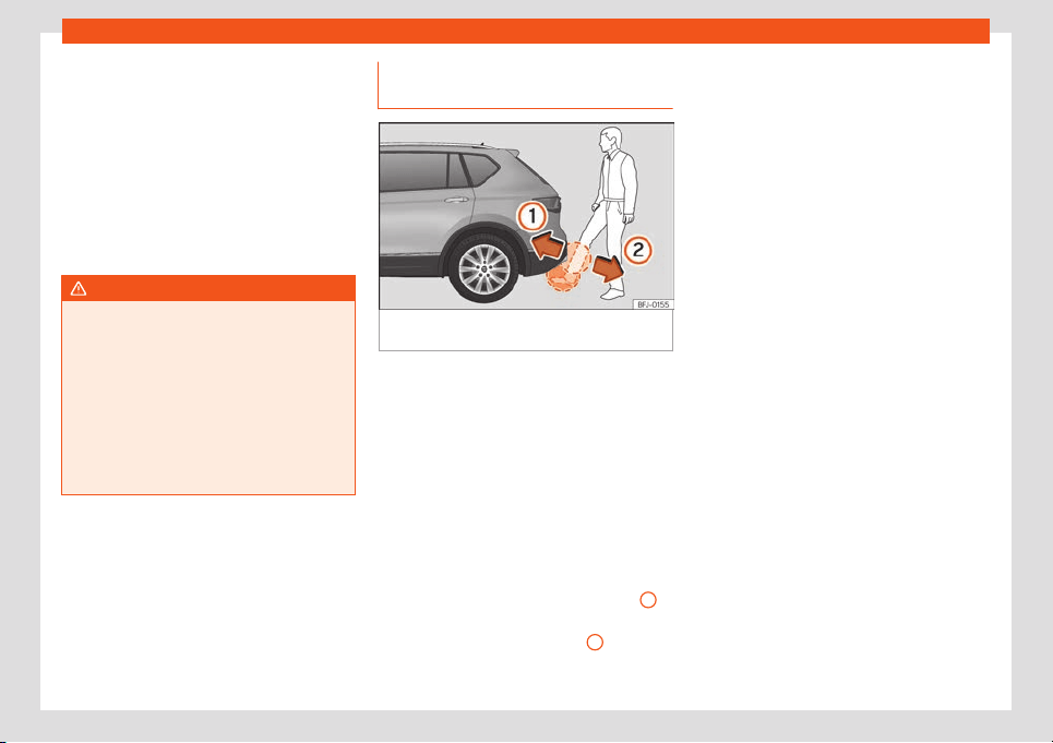
Opening and closing
be opened and closed by hand using reason-
abl
e f
or
ce
.
If with the r
ear lid open the v
ehicl
e battery is
disconnected
›››
page 358 or the corre-
sponding fuse burns out
›››
page 57, the sys-
tem will have to be reset. This requires closing
the rear lid completely once.
Emergency unlocking
›››
page 104
WARNING
If a lot of snow builds up on the rear lid or it
is heavily loaded, the rear lid may not open
or, after opening, it may low
er by itself due
to the extra weight and cause serious in-
jury.
●
Do not open the rear lid when there is a
lot of snow on it or when carrying a load
(e.g. on a rack).
●
Before opening the rear lid, remove the
snow or the load.
Rear lid with sensor-controlled
opening and cl
osing (Easy Open)
Fig. 87
Rear lid with sensor-controlled open-
ing (Easy Open).
If there is a valid vehicle key in the proximity
of the r
ear lid, it is possibl
e t
o unl
ock and
open or cl
ose it mo
ving one f
oot in the area of
the sensors located under the rear bumper.
●
Switch the ignition off.
●
Stand in front of the rear bumper, in the
middle.
●
With a brisk movement, bring your foot and
lower leg as close as you can to the bumper.
The lower part of the leg needs to be close to
the upper sensor area and your foot must be
close to the lower sensor area
›››
Fig. 87
1
.
●
Quickly remove your foot and lower leg
fr
om the sensor ar
eas
›
›
›
Fig. 87
2
. The rear
lid will be aut
omatically opened.
●
If the rear lid f
ail
s t
o open, r
epeat the pr
o-
cedur
e after a few seconds.
To notify that the rear lid has been opened
with the Easy Open function, the turn lights
blink twice.
The rear lid can be closed with another foot
movement similar to the opening one (provi-
ded a valid vehicle key is in the proximity of
the rear lid).
When closed, the rear lid automatically locks
if the vehicle has been locked beforehand
and there is no valid key inside.
While the rear lid is in motion (either opening
or closing), it can be stopped with another
foot movement similar to the opening one
(provided a valid vehicle key is in the proximi-
ty of the rear lid).
The Easy Open feature is not available or on-
ly has limited availability in the following sit-
uations (examples):
●
If the rear bumper is very dirty.
●
If the rear bumper is wet with salt water, e.g.
after having driven on gritted roads.
●
If the electrical unlocking tow hitch is not
covered.
●
If the vehicle has been equipped at a later
time with a tow bracket.
In the event of heavy rain, the Easy Open fea-
ture may take a little longer to open the boot
»
103
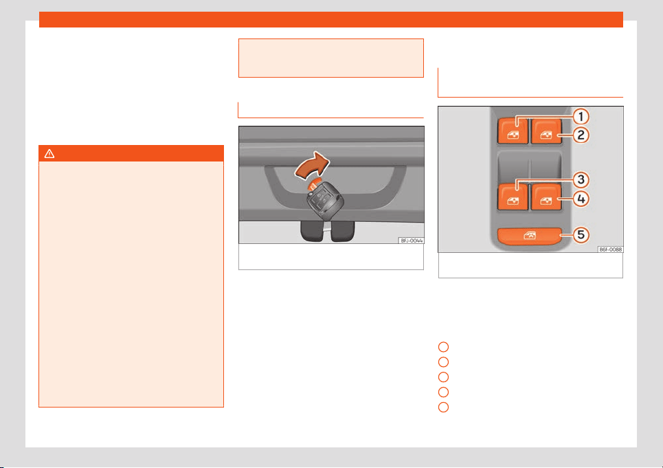
Operation
or may deactivate automatically, to avoid the
boot opening by accident, e
.g. because of
the running w
at
er
.
The Easy Open function can be connect
ed
and disconnect
ed permanently in the inf
o-
tainment system using the button > SET-
TINGS > Opening and closing
›››
page 82.
WARNING
If there is a valid key in the proximity of the
rear lid, in some cases the Easy Open func-
tion may be accidentally activated and the
rear lid will open, for e
xample, when
sweeping under the rear bumper, when di-
recting a water jet or high pressure steam
to the area or when carrying out mainte-
nance work or repairs in that area. If acci-
dentally opened, the rear lid could injure
somebody situated in its area of operation
or cause material damage.
●
Therefore, always make sure that there is
no unsupervised valid key in the area near
the rear lid.
●
Before carrying out any maintenance or
repair work on the vehicle, always disable
the Easy Open feature via the infotainment
system.
●
Before washing the vehicle, always disa-
ble the Easy Open feature via the infotain-
ment system.
●
Before attaching a bicycle rack or a trail
-
er,
›››
page 332, always disable the Easy
Open feature via the infotainment system.
Emergency unlocking of the rear lid
Fig. 88 Detail of the luggage compartment:
emer
gency unl
ocking
The rear lid can be unlocked from inside in
the e
v
ent of an emer
gency (e
.g. no batt
ery).
Ther
e is a gr
oove in the luggage compart-
ment allowing access to the emergency
opening mechanism.
Unlocking the rear lid from inside the lug-
gage compartment
●
Insert the key blade into the slot and press
the lever in the direction of the arrow until the
lock unlocks
›››
Fig. 88.
Window controls
Electrically opening and closing
the windows
Fig. 89
Detail of the driver's door: window
contr
ol
s.
●
Opening the window: press the button .
●
Closing the window: pull the button .
Butt
ons on the driv
er door
Windo
w on the fr
ont l
eft door
Windo
w on the fr
ont right door
Window on the rear left door
Window on the rear right door
Safety switch for deactivating the electric
window buttons in the rear doors.
1
2
3
4
5
104
Opening and closing
The front and rear electric windows can be
oper
at
ed by using the contr
ol
s on the driv
er
door
. The other doors each hav
e a switch for
their own window.
Always close the windows fully if you park the
vehicle or leave it unattended
›››
.
Y
ou can use the el
ectric windo
ws f
or appr
o
x.
10 minut
es after switching off the ignition if
neither the driver door nor the front passen-
ger door has been opened and the key has
not been removed from the ignition.
Safety switch *
The safety control
›››
Fig. 89
5
on the driver
door can be used t
o disabl
e the el
ectric win-
do
w butt
ons on the r
ear doors.
Saf
ety switch not pressed: buttons on rear
doors are activated.
Safety switch pressed: buttons on rear doors
are deactivated.
The safety control symbol lights up in yel-
low if the buttons on the rear doors are
switched off.
Convenience open/close function
The electric windows can be opened or
closed from outside using the vehicle key:
Convenience opening:
●
Press and hold the button on the remote
control key until all the windows and the sun-
roof* have reached the desired position.
●
OR: First unlock the vehicle using the but-
ton on the remote control key and then keep
the key in the driver door lock until all the win-
dows and the sunroof* have reached the re-
quired position.
Convenience closing:
●
Press and hold button on the remote
control key until all the windows and the sun-
roof* are closed
›››
.
●
OR: K
eep the key in the driver door in the
"l
ock" position until all the windo
ws and the
sunr
oof* ar
e cl
osed.
During conv
enience closing, first the windows
and then the sliding sunroof will be closed.
Different settings can be changed using the
Easy Connect system. Select: key > SET-
TINGS > Opening and closing > Window
operations > Convenience opening.
One-touch opening and closing
The one-touch automatic opening and clos-
ing is used to open or close the windows
completely. It will not be necessary to hold
the button of the corresponding electric win-
dow.
For the automatic raising function: pull the
button for the corresponding window up-
wards until it reaches the second position.
For the automatic lowering function: pull
the button for the corresponding window up-
wards until it reaches the second position.
Stop automatic movement: push or pull on
the button of the corresponding window.
Resetting one-touch opening and closing
The one-touch opening and closing function
is not active after the vehicle battery has
been disconnected or is flat and will have to
be reset.
●
Pull the button of the corresponding win-
dow and hold it for one second in this posi-
tion.
●
Release the button and pull upwards and
hold again. The one-touch function is now
ready for operation.
The automatic one-touch electric windows
can be reinitialised individually or several at a
time.
WARNING
Observe the safety warnings
›››
in Intro-
duction on page 98.
●
Incorrect use of the electric windows can
result in injury.
»
105

Operation
●
Never close the rear lid without observing
and ensuring it is clear, t
o do otherwise
could cause serious injury to you and third
parties. Make sure that no one is in the path
of a window.
●
If the ignition is switched on, the electric
equipment could be activated with risk of
injury, for example, in the electric windows.
●
The doors can be locked using the re-
mote control key. This could become an
obstacle for assistance in an emergency
situation.
●
Therefore always take the key with you
when you leave the vehicle.
●
The electric windows will work until the
ignition has been switched off and one of
the front doors has been opened.
●
If necessary, use the safety switch to dis-
able the rear electric windows. Make sure
that they have been disabled.
●
For safety reasons, you should only use
the remote control open and close func-
tions within about 2 metres of the vehicle.
To avoid injuries, always keep an eye on the
windows when pressing the button to close
them. The windows stop moving as soon as
the button is released.
Note
If the window is not able to close because it
is stiff or because of an obstruction, the
window will automatically open again
›››
page 106. If this happens, check why the
window could not be closed before at-
tempting to close it again.
Window anti-trap function
The roll-back function reduces the risk of in-
jury when the electric windows close.
●
If a window is obstructed when cl
osing au-
tomatically, the window stops at this point
and lowers immediately
›››
.
●
Next, check why the window does not close
bef
or
e att
empting it again.
●
If you try within the f
oll
o
wing 10 seconds
and the windo
w closes again with difficulty or
there is an obstruction, the automatic closing
will stop working for 10 seconds.
●
If the window is still obstructed, the window
will stop at this point.
●
If there is no obvious reason why the win-
dow cannot be closed, try to close it again by
pulling the tab within ten seconds. The win-
dow closes with maximum force. The roll-
back function is now deactivated.
●
If more than 10 seconds pass, the window
will open fully when you operate one of the
buttons. One-touch closing is reactivated.
WARNING
Observe the safety warnings
›››
in Elec-
trically opening and closing the windows
on page 105.
●
The roll-back function does not pre
vent
fingers or other parts of the body getting
pinched against the window frame. Risk of
accident.
Sunroof*
Introduction
The sunroof consists of two glass parts. The
r
ear part is fix
ed and cannot be opened. It al
-
so has a sun blind.
The sunr
oof only w
orks when the ignition is
s
wit
ched on. Once the ignition has been
switched off, you can still open or close the
sunroof for a few minutes provided the driver
door and the front passenger door are not
opened.
WARNING
If the sunroof is used negligently or without
paying due attention, it can cause serious
injury.
●
Open or close the sunroof and the sun
blind only when no one is in their path of
movement.
106
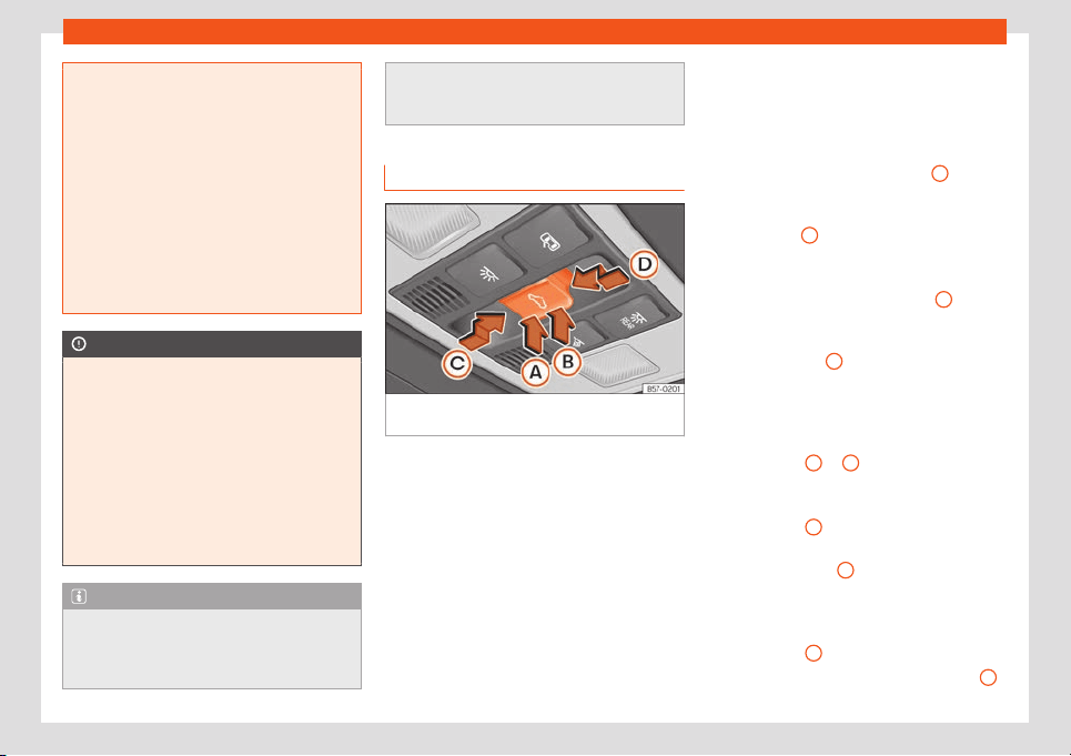
Opening and closing
●
Never leave any key inside the vehicl
e
when exiting.
●
Never leave a child or any other person
who may need help in the vehicle, espe-
cially if they have access to the vehicle
key. If using they key unattended, they
could lock the vehicle, start the engine,
switch on the ignition and activate the sun-
roof.
●
After switching off, it is still possible to
open or close the sunroof during a short
space of time provided that neither the
driver nor passenger door is opened.
CAUTION
●
To prevent damage, during winter t
em-
peratures remove any ice or snow that
might be on the car roof before opening the
sunroof or adjusting the tilt position.
●
Before leaving the vehicle or in case of
rainfall, always close the sunroof. With the
sunroof open or in a tilted position, water
can enter the interior and can cause con-
siderable damage to the electrical system.
As a result, other damage can occur in the
vehicle.
Note
●
Leaves and other loose objects that ac-
cumulate on the sunr
oof rails should be
regularly cleaned away either by hand or
with a vacuum.
●
If the sunroof does not work correctly, the
anti-trap function will not work either. Con-
t
act a specialised workshop.
Opening and closing the sunroof
Fig. 90 On the interior roof lining: sunroof but-
t
on.
The sun blind automatically opens along with
the sunr
oof if compl
et
ely cl
osed or if in fr
ont
of the sunr
oof
. The sun blind remains in the
previous position and does not automatically
close with the sunroof. The sun blind can only
be closed completely once the sunroof has
been closed.
The button
›››
Fig. 90 has two levels. The
first level switches the sunroof to the tilted po-
sition, opening or closing it fully or partially.
On the second level, the sunroof automati-
cally moves to the corresponding final posi-
tion after briefly pressing the button. Activat-
ing the button again stops the automatic
function.
Adjusting the tilt position of the sunroof
●
Press the rear part of the button
B
to the
first l
e
v
el.
●
Aut
omatic function: briefly pr
ess the r
ear
part of butt
on
B
to the second level.
Cl
osing the sunr
oof fr
om a tilt
ed position
●
Pr
ess the fr
ont part of the butt
on
A
to the
first l
e
v
el.
●
Aut
omatic function: briefly pr
ess the fr
ont
part of the butt
on
A
to the second level.
St
opping the aut
omatic oper
ation by ad-
justing the tilt
ed position of the sunr
oof or
by cl
osing the sunr
oof
●
Press button
A
or
B
again.
Opening the sunr
oof
●
Pr
ess butt
on
C
backwards to the first level.
●
Automatic function to the comfort position:
briefly pr
ess butt
on
C
backwards to the sec-
ond l
e
v
el.
Cl
osing the sunr
oof
●
Pr
ess butt
on
D
forwards to the first level.
●
Automatic function: briefly press button
D
forwards to the second level.
»
107
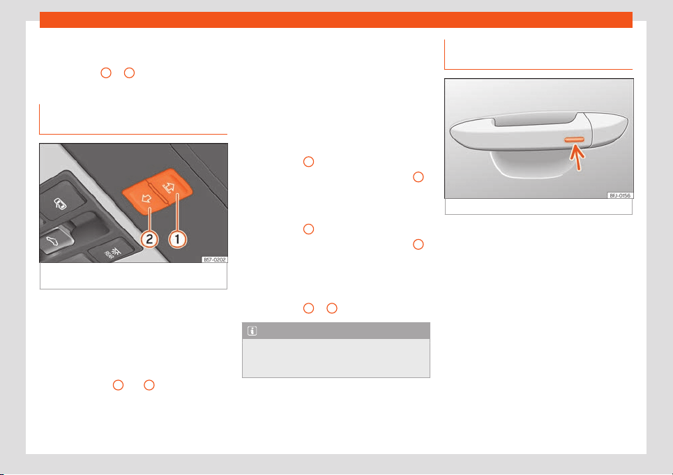
Operation
Stopping the automatic operation during
the opening or cl
osing
●
Pr
ess butt
on
C
or
D
again.
Opening and closing the sunshade
blind
Fig. 91
On the interior roof lining: sunshade
blind butt
ons.
The electrical sun blind works when the igni-
tion is s
wit
ched on.
When the sunr
oof is in its most tilt
ed position,
the sun blind aut
omatically goes int
o a v
enti-
lation position. The sun blind remains in this
position also with the sunroof closed.
Buttons
›››
Fig. 91
1
and
2
have two levels.
The first l
e
v
el opens or cl
oses the sun blind
fully or partially.
By briefly pr
essing the butt
on t
o the second
level, the sun blind automatically moves to
the corresponding final position. Activating
the button again stops the automatic func-
tion.
Once the ignition has been switched off, you
can still open or close the sun blind for a few
minutes provided the driver door and the
front passenger door are not opened.
Opening the sun blind
●
Press button
1
to the first level.
●
Automatic function: briefly press button
1
to the second level.
Cl
osing the sun blind
●
Pr
ess butt
on
2
to the first level.
●
Automatic function: briefly press button
2
to the second level.
St
opping the aut
omatic oper
ation during
the opening or cl
osing
●
Pr
ess butt
on
1
or
2
again.
Note
When the sunroof is open, the electric sun
blind can only be closed to the front edge
of the sunroof.
Convenience function to open or
cl
ose the sunr
oof*
Fig. 92
Door handle: sensor surface.
The sunroof can be opened and closed with
the conv
enience function, just lik
e the win-
do
ws.
Using the door l
ock*
●
Hol
d the k
ey in the door l
ock of the driver
door in either the unlocking or locking posi-
tion to open or close the roof in the tilted po-
sition. Release the key to interrupt this func-
tion.
Using the remote control
●
Keep the locking or unlocking button press-
ed to open or close the roof. If you release the
button is the opening or closing will stop.
108
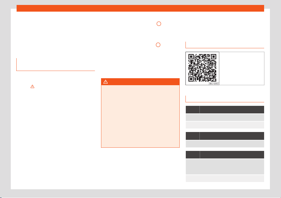
Lights
Using the Keyless Access* system (only
cl
osing)
●
Pr
ess and hol
d the l
ocking sensor surf
ace
›
›
›
Fig. 92 (arrow) on the door handle to close
the sunroof. If you release the sensor surface,
the closing movement stops.
Anti-trap function of the panoramic
sunroof and sunshade
The anti-trap function can reduce the risk of
injury when cl
osing the sunr
oof and the sun
blind
›
›
›
. If the sunroof or sun blind encoun-
t
er r
esist
ance or an obst
acl
e when cl
osing,
they r
eopen immediately.
●
Check why the sunroof or sun blind do not
close.
●
Try to close the sunroof or sun blind again.
●
If the sunroof or sun blind cannot be closed
due to an obstacle or some resistance, it
stops at the corresponding position and then
opens. For automatic closing, a new closing
attempt might take place.
●
If the sunroof or sun blind is still unable to
close, close it without the anti-trap function.
Closing the sunroof or sun blind without
the anti-trap function
●
Sunroof: within approximately 5 seconds of
having activated the roll-back function, press
the button
›››
Fig. 90 to the second level in
the direction of arrow
›››
Fig. 90
D
until the
sunr
oof cl
oses compl
et
ely.
●
Sunshad
e blind:
within appr
oximately
5 seconds of having activated the anti-trap
function, press button
›››
Fig. 91
2
until the
sun blind cl
oses compl
et
ely.
●
The sunr
oof or sun blind cl
ose without
the anti-tr
ap function int
ervening!
●
If the sunroof or sun blind will still not close,
visit a specialised workshop.
WARNING
Closing the sunroof or sun blind without the
anti-trap function can cause serious inju-
ries.
●
Always be careful when closing the sun-
roof and sun blind.
●
No person shoul
d ever remain in the way
of the sunroof or sun blind, especially when
closing without the anti-trap function.
●
The anti-trap function does not prevent
fingers or other parts of the body from be-
coming trapped against the roof frame and
injuries occurring.
Lights
V
ehicl
e lighting
R
el
at
ed video
Fig. 93 Lights and visibil-
it
y
Control lamps
It lights up
Driving light totally or partially faulty.
Fault in the cornering light system.
It lights up
Rear fog light switched on
›››
page 111.
It lights up
Left or right turn signal.
The control lamp flashes twice as fast when a turn
signal is fault
y.
Hazard warning lights on
›››
page 115.
»
109
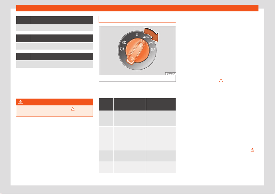
Operation
It lights up
Trailer turn signals
It lights up
Main beam on or flasher on
›››
page 112.
It lights up
The Light Assist system is on
›››
page 113.
Several warning and control lamps light up
for a few seconds when the ignition is switch-
ed on, signalling that the function is being
verified. They will s
witch off after a few sec-
onds.
WARNING
Observe the safety warnings
›››
in Con-
trol and warning lamps on page 81.
Headlight switch
Fig. 94
Dash panel: lights control.
●
Turn the switch to the required position
›
›
›
Fig. 94
.
Sym-
bol
Ignition switch-
ed off
Ignition is
switched on
Fog lights, dipped
beam and side
lights off.
Daylight running
lights switched on.
The “Coming
home”, “Leaving
home” and Wel-
come lights may be
s
witched on.
Automatic contr
ol
of dipped beam
and daytime run-
ning light.
Side light on.
Daylight running
lights switched on.
Dipped beam head-
light off
Dipped beam
switched on.
The driver is personally responsible for the
corr
ect use and adjustment of the lights in all
sit
uations.
Aut
omatic dipped beam headlight contr
ol
*
The aut
omatic dipped beam control is merely
intended as an aid and is not able to recog-
nise all driving situations.
When the light switch is in position , the
vehicle lights and the instrument panel and
switch lighting switch on automatically in the
following situations
›››
:
●
The photo sensor detects d
arkness
, f
or e
x-
ampl
e
, when driving thr
ough a tunnel. They
switch off when adequate lighting is detec-
ted.
●
The rain sensor detects rain and activates
the wipers. They switch off when the wipers
have not been activated for a few minutes.
Daytime running lights
The daytime running lights consist of individu-
al lights, integrated in the front headlights.
When the daytime running lights are switched
on, the rear side light also switches on
›››
.
The daytime running lights t
urn on e
v
ery time
the ignition is s
wit
ched on, if the s
wit
ch is in
position or , according to the level of ex-
terior lighting.
110
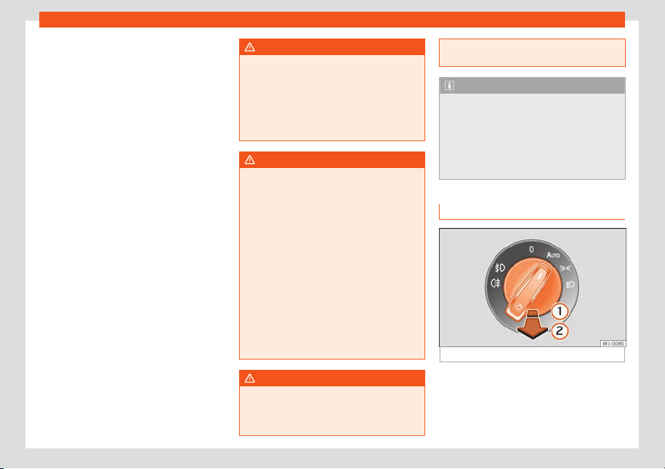
Lights
When the light switch is in position
, a light
sensor aut
omatically s
wit
ches dipped beam
on and off (including the contr
ol and instru-
ment lighting) or the daytime running lights
depending on the level of exterior lighting.
Motorway light*
The function is connected and disconnected
via the corresponding Easy Connect system
menu.
●
Activation: when going above 110 km/h
(68 mph) for more than 30 seconds, the dip-
ped beam raises slightly to increase the driv-
er's visibility distance.
●
Deactivation: when reducing the speed of
the vehicle below 100 km/h (62 mph), the
dipped beam immediately returns to its nor-
mal position.
Audible warnings to advise the driver that
the lights have not been switched off
If the key is not in the ignition and the driver
door is open, an audible warning signal is
heard in the following cases: this will remind
you to turn the light off.
●
When the parking light is on
›››
page 112.
●
When the light switch is in position or .
WARNING
If the road is not well lit and other road
users cannot see the vehicle well enough
or at all, accidents may occur.
●
The automatic dipped beam control
(
) only switches on the dipped beam
when there are changes in light conditions
but not, for example, when it is foggy.
WARNING
The side lights or daytime running lights
are not bright enough to illuminate the road
ahead and to ensure that other r
oad users
are able to see you.
●
Always use your dipped beam head
lights if it is raining or if visibility is poor.
●
Never drive with daytime lights if the road
is not well lit due to weather or lighting
conditions.
●
On vehicles with rear lights with bulbs,
when activating the daytime running light
the rear lights are not switched on. A vehi-
cle which does not have the rear lights on
may not be visible to other drivers in the
darkness, in the case of heavy rain or in
conditions of poor visibility.
WARNING
If the headlights are set too high and not
used correctly, there is a risk of dazzling or
distracting other road users. This could re-
sult in a serious accident.
●
Always make sure that the headlights are
correctly adjust
ed.
Note
●
The l
egal requirements regarding the use
of vehicl
e lights in each country must be
observed.
●
The dipped beam headlights will only
work with the ignition on. The side lights
come on automatically when the ignition is
turned off.
Fog lights
Fig. 95 Dash panel: lights control.
The warning lamps or al
so sho
w
, on the
light s
wit
ch or instrument panel, when the
fr
ont f
og lights are on.
»
111
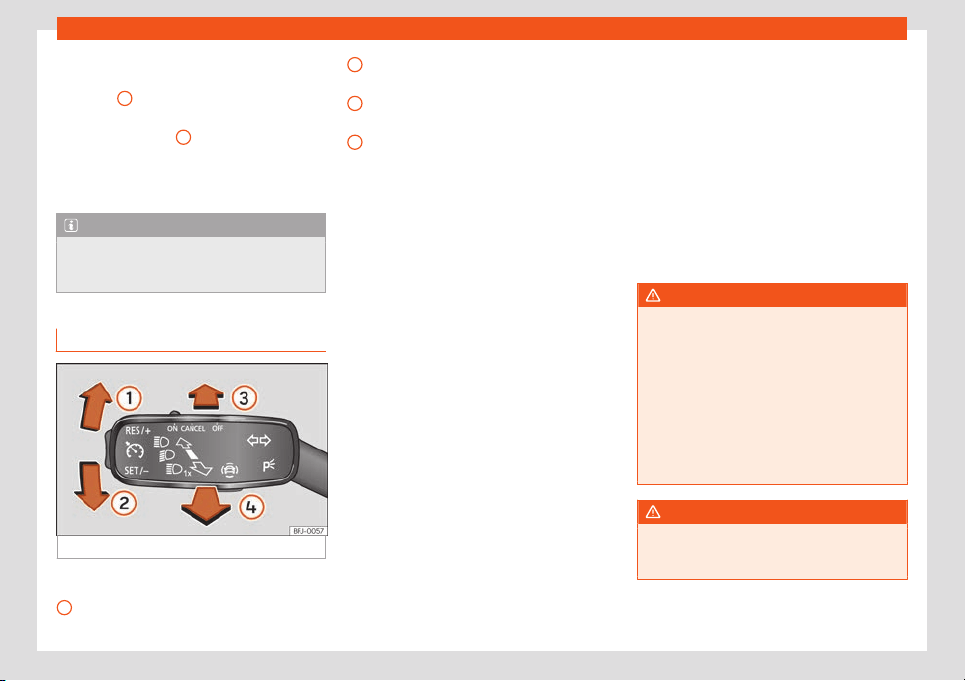
Operation
●
T
urning on the fr
ont f
og lights*
: pull the
light s
wit
ch out to its first click position
›››
Fig. 95
1
, from positions , or .
●
Turning on the rear fog light : pull the
light s
wit
ch fully out
2
from position , or
.
●
T
o s
wit
ch off the f
og lights, pr
ess the light
switch or turn it to position .
Note
The rear fog light can dazzle drivers behind
you. You should use the rear fog light only
when visibility is very poor
.
Turn signal and main beam lever
Fig. 96
Turn signal and main beam lever.
More the lever to the required position:
Right t
urn light or right
-hand parking light
(ignition s
wit
ched off).
1
Left turn light or left-hand parking light
(ignition s
wit
ched off).
Main beam on: contr
ol l
amp
lit up on
the instrument panel.
Light fl
ash: on with the lever pushed. Con-
trol lamp lit up.
Push the lever all the way down to turn off the
corresponding function.
Convenience turn signals
When the ignition is switched on, move the
lever as far as possible upwards or down-
wards and release the lever. The turn signal
will flash three times.
The convenience turn signal can be activated
and deactivated in the Easy Connect system
using the key > SETTINGS > Lighting >
Light assistance > Convenience turn
signal
›››
page 82.
In vehicles that do not have the correspond-
ing menu, this function can be deactivated in
a specialised workshop.
Parking light
The parking lights will only work with the igni-
tion off. If said light is on, an audible warning
will sound while the driver door is open.
●
Switch the ignition off.
●
Move the turn signal lever up or down.
2
3
4
When the parking light is switched on, the
fr
ont side light and the t
ail light on the corr
e-
sponding side of the v
ehicl
e t
urn on.
P
arking light on both sides
●
Switch the ignition off.
●
Place the light switch in position .
●
Lock the vehicle from the outside.
In doing so, only the side lights of both head-
lights light up, and additionally the tail lights
will do so partially.
WARNING
Improper or lack of use of the turn signals,
or forgetting to deactivate them can con-
fuse other road users. This coul
d result in a
serious accident.
●
Always give warning when you are going
to change lane, overtake or when turning,
activating the turn signal in good time.
●
As soon as you have finished changing
lane, overtaking or turning, switch the turn
signal off.
WARNING
Incorrect use of the headlights may cause
accidents and serious injury, as the main
beam may distract or dazzle other drivers.
112
Lights
Note
●
If the convenience turn signals are oper-
ating (three fl
ashes) and the other conven-
ience turn signals are switched on, the ac-
tive part stops flashing and only flashes
once in the new part selected.
●
The turn signal only works when the igni-
tion is switched on. The hazard warning
lights also work when the ignition is switch-
ed off.
●
If a trailer turn signal malfunctions, the
control lamp will stop flashing (trailer turn
signals) and the vehicle turn signal will
flash at double speed.
●
The main beam headlights can only be
switched on if the dipped beam headlights
are already on.
●
In cold or damp weather conditions, the
headlights, tail lights and turn signals may
mist up inside temporarily. This is normal
and in no way effects the useful life of the
vehicle lighting system.
●
The parking light does not activate auto-
matically if the left- or right-hand turn sig-
nal is left on and the ignition is disconnec-
ted.
Main beam assist (Light Assist)*
The main beam assist acts within the limits of
the syst
em and depending on envir
onment
al
and tr
affic conditions. Once s
wit
ched on, the
syst
em is activated as of a speed of about 60
km/h (37 mph) and is deactivated below
about 30 km/h (18 mph)
›››
.
When the syst
em is activ
at
ed and the cam-
er
a det
ects other v
ehicl
es that may be daz-
zled, the main beam is automatically switch-
ed off. Otherwise, the main beam is automati-
cally switched on.
The main beam assist generally detects illu-
minated areas and deactivates the main
beam when passing through a town, for ex-
ample.
Switching the main beam assist on
●
Turn on the ignition and turn the light switch
to the position .
●
From the base position, press the turn signal
and main beam headlights lever forwards
›››
Fig. 96
3
When the lamp is displ
ayed
on the instrument panel displ
ay, the main
beam assist is s
wit
ched on.
S
wit
ching the main beam assist off
●
T
urn the light switch to a position other than
›››
page 110.
●
OR: while the main beam is on, pull the turn
signal light and main beam headlights lever
forwards
›››
Fig. 96
4
.
●
OR: push the t
urn signal and main beam
headlight l
e
v
er f
orw
ar
ds to manually turn on
the main beam. The main beam assist will
then be deactivated.
Malfunctions
The following conditions may prevent the
main beam headlight control from turning off
the headlights in time or from turning off alto-
gether:
●
In poorly lit towns with highly reflective
signs.
●
Other insufficiently lit road users (such as
pedestrians or cyclists).
●
On tight bends and steep slopes (bumps)
and when oncoming vehicles are partially
obscured.
●
When the drivers of other oncoming vehi-
cles (such as a truck) can see over a guard
rail in the centre of the road.
●
If the camera is damaged or the power
supply is cut off.
●
In fog, snow and heavy rain.
●
With dust and sand turbulence.
●
With loose gravel in the field of vision of the
camera.
●
When the field of vision of the camera is
misted up, dirty or covered by stickers, snow,
ice, etc.
»
113
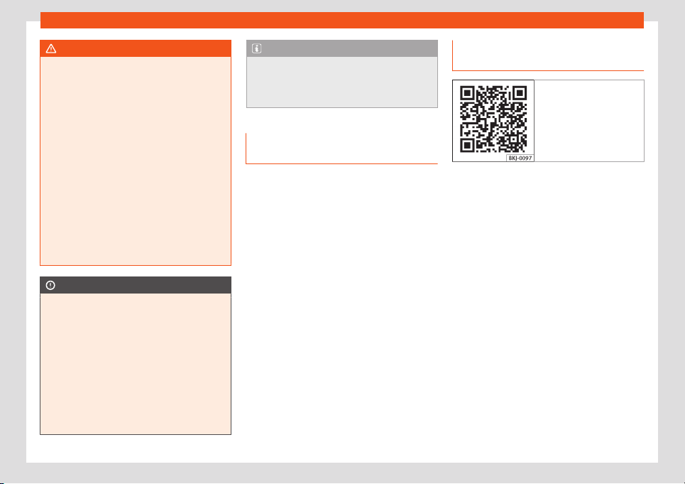
Operation
WARNING
The convenience features of the main
beam assist should not encourage the tak-
ing of risks. The system is not a repl
ace-
ment for driver concentration.
●
You are always in control of the main
beam and adapting it to the light, visibility
and traffic conditions.
●
It is possible that the main beam head-
light control does not recognise all driving
situations and is limited under certain cir-
cumstances.
●
When the field of vision of the camera is
dirty, covered or damaged, operation of
the main beam control may be affected.
This also applies when changes are made
to the vehicle lighting system, for example,
if additional headlights are installed.
CAUTION
To avoid affecting the operation of the sys-
tem, take the following points int
o consid-
eration:
●
Clean the field of vision of the camera
regularly and make sure it is free of snow
and ice.
●
Do not cover the field of vision of the
camera.
●
Check that the windscreen is not dam-
aged in the area of the field of vision of the
camera.
Note
Main beam and headlight flasher can be
turned on and off manually at any time with
the turn signal and main beam lever
››
›
page 112.
Fog lights with cornering light func-
tion*
The cornering light function is an additional
function to the dipped beam headlights to
improve lighting of the side of the road when
t
aking a sharp turn at low speed.
The cornering light function works when the
dipped beam headlights are already on and
it is activated when driving at speeds below
approximately 40 km/h (25 mph).
●
If the steering wheel is turned or the turn
signal is switched on, the front fog light grad-
ually turns on. Aft
er the turn, the cornering
light function is gradually switched off.
●
When engaging reverse gear, both front fog
lights turn on.
“Coming home” and “Leav-
ing home” function
Fig. 97 Related video
The “Coming home” and “Leaving home”
function lights up the vehicle’s immediate
pro
ximity when getting into and out of it in the
dark. When switched on, the front position
and dipped beam lights, tail lights and li-
cense plate light come on.
The “Leaving Home” is controlled by a photo-
sensor.
In the vehicle settings menu of the infotain-
ment system you can adjust the duration of
the light switch-off delay, and activate and
deactivate the function.
Activating the “Coming Home” function
For vehicles with light and rain sensors.
●
Switch off the engine and remove the key
from the ignition with the light switch in posi-
tion
››
›
page 110.
●
The automatic “Coming Home” function is
only active when the light sensor detects
darkness.
114
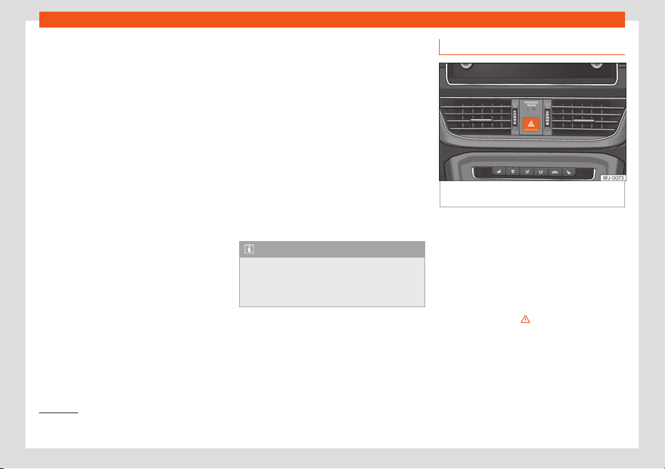
Lights
For vehicles without light and rain sensors.
●
Switch the ignition off.
●
Activate the headlight flashers for appr
o
xi-
mat
ely 1 second
.
When the driv
er door is opened, the “Coming
Home” lighting comes on. The
d
elay in
switching off the headlights is counted from
when the last door or boot hatch is closed.
The “Coming Home” lighting turns off in
the following cases:
●
Automatically, once the headlight turn off
delay has elapsed.
●
Automatically, when a vehicle door or the
rear lid is still open 30 seconds after starting
the engine.
●
When the rotary light switch is turned to po-
sition
›››
page 110.
●
With the ignition is switched on.
Activating the “Leaving Home” function
●
Unlock the vehicle using the remote control.
●
The “Leaving Home” function is only activa-
ted when the light switch is in position
and the light sensor detects darkness.
The “Leaving Home” lighting switches off
in the following cases:
●
Automatically, when the “Leaving Home”
delay period ends (default 30 sec).
●
When the vehicle is locked using the remote
control.
●
When the light switch is turned to position .
●
With the ignition is switched on.
Welcome light*
1)
The welcome light is a light located on the
exterior mirrors, focused on the ground, which
activates or deactivates if the light switch is in
the position and the “Coming Home” or
“Leaving Home” function is turned on or off.
Note
To activate the “Coming Home” and “Leav-
ing Home” function, the rotary light switch
must be in position and the light sensor
must det
ect darkness.
Hazard warning lights
Fig. 98
Dash panel: hazard warning lights
s
wit
ch
The hazard warning lights are used to draw
the att
ention of other r
oad users t
o your v
ehi-
cl
e in emer
gencies.
If your v
ehicle breaks down:
1. Park your vehicle at a safe distance from
moving traffic.
2. Press the button to switch on the hazard
warning lights
›››
.
3. Switch the ignition off.
4. Apply the electronic parking brake.
»
1)
Valid for vehicles with a light and rain sensor
and full-LED headlights.
115

Operation
5. For a manual gearbox, engage 1st gear;
f
or an aut
omatic gearbo
x, mo
v
e the gear
l
e
ver to P.
6. Use the warning triangle to draw the at-
tention of other road users to your vehicle.
7. Always take the vehicle key with you when
you leave the vehicle.
All turn signals flash simultaneously when the
hazard warning lights are switched on. The
two turn signal turn signal lamps and the
turn signal lamp in the switch will flash at
the same time. The simultaneous hazard
warning lights also work when the ignition is
switched off.
Emergency braking warning
If the vehicle brakes suddenly and continu-
ously at a speed of more than 80 km/h (50
mph), the brake light flashes several times per
second to warn the vehicles driving behind. If
you continue braking, the hazard warning
lights will come on automatically when the
vehicle comes to a standstill. They switch off
automatically when the vehicle starts to
move again.
WARNING
●
The risk of an accident increases if your
vehicle breaks down. Alw
ays use the haz-
ard warning lights and a warning triangle to
draw the attention of other road users to
your stationary vehicle.
●
Due to the high temperatures that the
catalytic conv
erter can reach, never park
in an area where the catalytic converter
could come into contact with highly inflam-
mable materials, for example dry grass or
spilt petrol. This could start a fire.
Note
●
The batt
ery will run down if the hazard
warning lights are l
eft on for a long time,
even if the ignition is switched off.
●
The use of the hazard warning lights de-
scribed here is subject to the relevant stat-
utory requirements.
Dynamic headlight range control
The headlight range is automatically adjus-
t
ed accor
ding t
o the v
ehicl
e l
oad st
atus when
they are switched on.
WARNING
Heavy objects in the vehicle may mean
that the headlights dazzle and distract oth-
er drivers. This could result in a serious ac-
cident.
Driving abroad
The light beam of the dipped beam lights is
asymmetric: the side of the road on which
you are driving is lit more intensely.
When a car that is manufactur
ed in a country
that drives on the right travels to a country
that drives on the left (or vice versa), it is nor-
mally necessary to cover part of the head-
light bulbs with stickers or to change the ad-
justment of the headlights to avoid dazzling
other drivers.
In such cases, the regulations specify certain
light values that must be complied with for
designated points of the light distribution. This
is known as “Tourist light”.
The light distribution of the full-LED head-
lights allows the specific “tourist light” values
to be met without the need for stickers or
changes in the settings.
Note
“Tourist light” is only allowed temporarily. If
you are planning a long stay in a country
that drives on the other side, you shoul
d
take the vehicle to an Authorised Technical
Service to change the headlights.
116
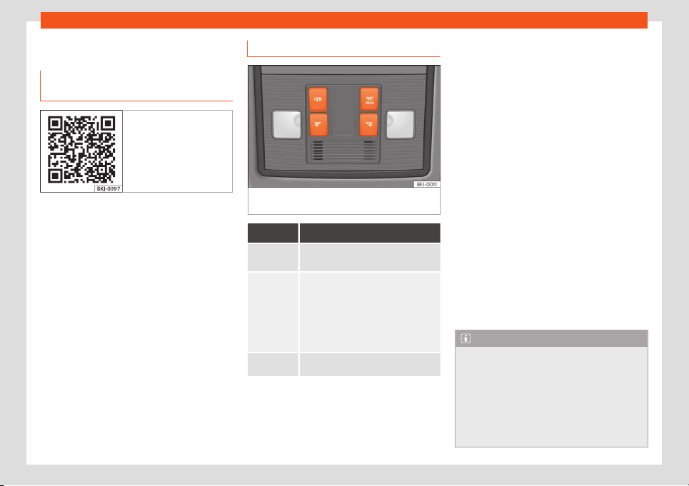
Lights
Interior lights
Lighting of the instrument panel
,
displ
ays and s
wit
ches
Fig. 99 Related video
Depending on the model, the lighting of the
instrument panel and s
wit
ched can be adjus-
t
ed in the Easy Connect syst
em, using the
butt
on
> SETTINGS
›››
page 82.
With the ignition on and without light activa-
tion, the analogue instrument panel lighting
remains activated in daytime light conditions.
The lighting is reduced as the exterior light di-
minishes. In some cases, e.g. when driving
through a tunnel without the function ac-
tive, the instrument panel lighting may even
switch off. The objective of this function is to
provide the driver with a visual indication that
he or she should activate the dipped beam.
If your vehicle is equipped with a digital in-
strument panel (Digital SEAT Cockpit), the
following message will appear Turn on the
lights on the instrument panel.
Interior and reading lights
Fig. 100
Detail of roof lining: front lighting of
the passenger compartment.
Knob Function
Turning the rear interior lights on or
off.
The interior lights come on automati-
cally when you unlock the vehicle
,
open a door or remov
e the key from
the ignition.
The light goes out a few seconds after
closing all the doors, when locking the
vehicle or connecting the ignition.
/
Turning the reading light on and off
Glove compartment and luggage com-
par
tment lighting*
When opening and cl
osing the gl
o
v
e com-
partment on the fr
ont passenger side and the
r
ear lid, the respective light will automatically
switch on and off.
Footwell lighting*
The lights in the footwell area below the dash
(driver and front passenger sides) will switch
on when the doors are opened and will de-
crease in intensity while driving. This intensity
setting can be changed through the infotain-
ment system menu (key > SETTINGS >
lIGHTING > Interior lighting
›››
page 82).
Ambient light*
The ambient light lights up the area of the
centre console and the footwell area and,
depending on the version, the front door pan-
els as well.
The intensity of the ambient light can be ad-
justed using the menu Easy Connect menu
(button) > SETTINGS > Background
lighting
›››
page 82).
Note
●
Depending on the features fitted in the
vehicle
, LEDs can be used for the following
interior lights: front vanity mirror light, rear
vanity mirror light, footwell light, sun blind
and glove compartment light.
●
The reading lights switch off when the ve-
hicle is locked using a key or after several
minutes if the key is removed from the
»
117
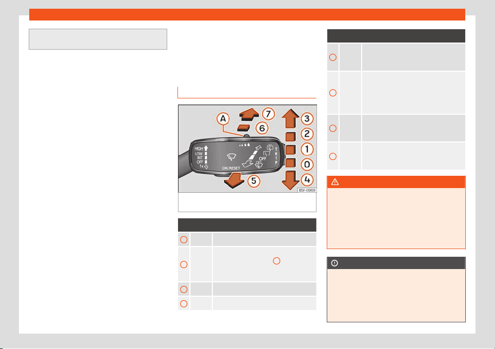
Operation
ignition. This prevents the battery from dis-
charging.
Visibility
Windscr
een wiper and r
ear
windo
w wiper syst
ems
Windo
w w
asher l
ever
Fig. 101
Operating the windscreen wiper and
r
ear wiper
.
More the lever to the required position:
0
Windscreen wipers off.
1
Wiper intervals.
Use control
›››
Fig. 101
A
to set the in-
t
erv
al (v
ehicl
es without r
ain sensor), or
the sensitivit
y of the r
ain sensor.
2
Slow wipe.
3
Continuous wipe.
More the lever to the required position:
4
Short wipe. Brief press, short clean.
Hold the lever down for mor
e time to in-
crease the wipe frequency.
5
Windscreen washer. The windscreen
washer function is activated by push-
ing the lever towards the steering
wheel, and the wipers operate simulta-
neously.
6
Interval wipe for rear window. The wip-
er will wipe the window approximately
every six seconds.
7
The rear window wash function is acti-
vated by pressing the lever
, and the
rear wiper starts simultaneously.
WARNING
In cold conditions you should not use the
wash/wipe system unless you have
warmed the windscreen with the heating
and v
entilation system. The windscreen
washer fluid could otherwise freeze on the
windscreen and obscure your view of the
road.
CAUTION
If the ignition is switched off with the wind-
screen wipers active, they complete their
wipe befor
e returning to the rest position.
When switching the ignition back on, the
windscreen wiper will continue to operate
at the same wiping level. Ice, snow and
118
Visibility
other obstacles on the windscreen may
damage the wiper and the windscreen wip-
er motor.
●
If necessary, remove sno
w and ice from
the windscreen wipers before starting your
journey.
●
Carefully lift the frozen windscreen wip-
ers from the glass. SEAT recommends a de-
icer spray for this operation.
●
Do not switch on the windscreen wipers if
the windscreen is dry. Cleaning with the
windscreen wipers while dry can cause
damage.
●
In icy conditions, always check that the
wiper blades are not frozen to the glass be-
fore using the wipers. In cold weather, it
may help to leave the vehicle parked with
the wipers in service position
›››
page 49.
Note
●
The windscreen and window wipers only
function when the ignition is switched on
and the bonnet or rear lid, respectiv
ely, are
closed.
●
The interval wipe speed varies according
to the vehicle speed. The faster the vehicle
is moving, the more often the windscreen is
cleaned.
●
The rear wiper is automatically switched
on when the windscreen wiper is on and the
car is in reverse gear.
Wiper functions
Windscreen wipers performance in differ-
ent situations
●
If the vehicle is stopped, the activated posi-
tion t
emporarily moves to the previous posi-
tion.
●
The air conditioner comes on for approxi-
mately 30 seconds in air recirculation mode
when the windscreen washer is activated,
to prevent the smell of the windscreen wash-
er fluid entering the inside the vehicle.
●
When wiping at intervals, the intervals vary
according to the speed. The higher the vehi-
cle speed the shorter the interv
als.
Heated windscreen washer jets*
The heating only thaws the frozen jets, it does
not thaw the water in the washer hoses.
When the ignition is switched on the heated
windscreen washer jets automatically adjust
the heat depending on the ambient tempera-
ture.
Note
●
The wiper will try to wipe away any ob-
stacles that are on the windscreen. The
wiper will st
op moving if the obstacle
blocks its path. Remove the obstacle and
switch the wiper back on again.
●
If you stop the vehicle with the wind-
screen wiper in position 1 or 2, it will auto-
matically change to a lower position
speed. The set speed will be resumed when
the vehicle pulls away.
●
The windscreen will be wiped again ap-
pr
oximately 5 seconds after the wind-
screen washer has been activated, provi-
ded the vehicle is moving (“drip” function).
If you activate the wipers less than 3 sec-
onds after the “drip” function, a new wash
sequence will begin without performing the
last wipe. For the “drip” function to work
again, you have to turn the ignition off and
then on again.
119
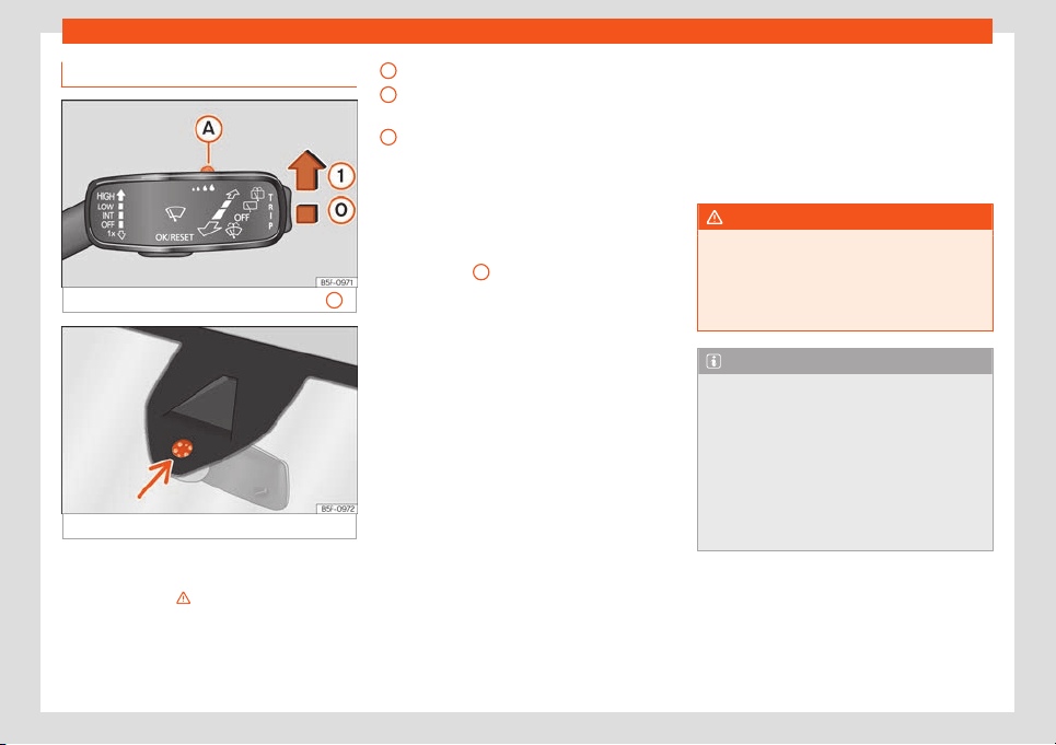
Operation
Rain sensor*
Fig. 102
Wiper lever: adjust the rain sensor
A.
Fig. 103
Rain sensor sensitive surface
The rain sensor controls the frequency of the
windscr
een wiper int
erv
al
s, depending on the
amount of r
ain
›
›
›
. The sensitivity of the rain
sensor can be adjust
ed manually. Manual
wipe
›
›
›
page 1
18
.
Mo
ve the lever to the required position
›››
Fig. 102:
Rain sensor off.
Rain sensor on; automatic wipe if neces-
sary.
Setting sensitivity level of rain sensor
–
Set control to the right: high sensitivity.
–
Set control to the left: low sensitivity.
When the ignition is switched off and then
back on, the rain sensor stays on and starts
operating again when the windscreen wipers
are in position
1
and the vehicle is travelling
at mor
e than 16 km/h (
10 mph).
Modified behaviour of the r
ain sensor
P
ossibl
e causes of f
aults and mist
aken read-
ings on the sensitive surface
›››
Fig. 103 of the
rain sensor include:
●
Damaged wipers: a film of water on the
damaged blades may lengthen the activa-
tion time, reduce the washing intervals or re-
sult in a fast and continuous wipe.
●
Insects: insects on the sensor may trigger
the windscreen wiper.
●
Salt on the road: in winter, salt spread on
the roads may cause an excessively long
wipe when the windscreen is almost dry.
●
Dirt: dry dust, wax, coating on glass (Lotus
effect) or traces of detergent (car wash) may
reduce the effectiveness of the rain sensor or
make it react more slowly, later or not at all.
0
1
A
●
Windscr
een cr
ack: the impact of a st
one
will trigger a singl
e wipe cycl
e with the r
ain
sensor on. Ne
xt the rain sensor detects the re-
duction in the sensitive surface area and
adapts accordingly. The behaviour of the
sensor will vary with the size of the damage
caused by the stone.
WARNING
The rain sensor may not detect enough rain
to switch on the wipers.
●
If necessary, switch on the wipers man-
ually when wat
er on the windscreen ob-
structs visibility.
Note
●
Clean the sensitive surface of the rain
sensor regularly and check the bl
ades for
damage
›››
Fig. 103 (arrow).
●
To remove wax and coatings, we recom-
mend a window cleaner containing alco-
hol.
●
Do not put stickers on the windscreen in
front of the rain sensor*. This may cause
sensor disruption or faults.
120
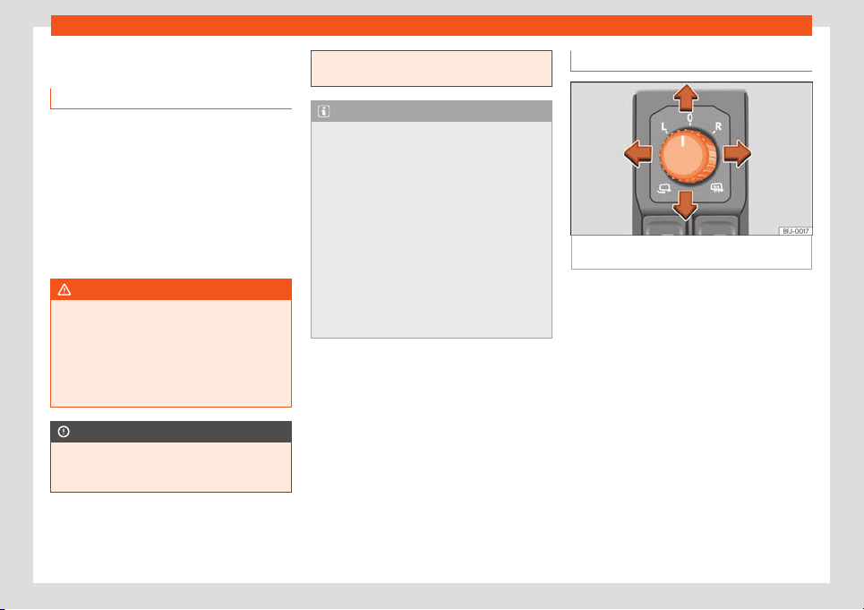
Visibility
Mirrors
Int
erior mirr
or anti-dazzl
e function
Rear view mirror with automatic anti-daz-
zle function
The anti-dazzle function is activated every
time the ignition is s
witched on.
When the anti-dazzle function is enabled, the
interior rear vision mirror will darken auto-
matically according to the amount of light it
receives. The anti-dazzle function is cancel-
led if reverse gear is engaged.
WARNING
In the event that an automatic anti-dazzle
rear vision mirror breaks, an electrolyte flu-
id may l
eak. This could cause irritation to
the skin, eyes and respiratory organs. If you
come into contact with this liquid, it must
be rinsed with large quantities of water. If
necessary, get medial help.
CAUTION
In the event that an automatic anti-dazzle
rear vision mirror breaks, an electrolyte flu-
id may l
eak. This liquid attacks plastic sur-
faces. Clean it with a wet sponge as soon
as possible.
Note
●
If the light incident in the int
erior rear vi-
sion mirror is obstructed (e.g. with the sun
blind*), the anti-dazzle r
ear vision mirror
with automatic setting will not operate per-
fectly.
●
When the interior lights are on or reverse
gear engaged, the mirrors do not darken
with automatic adjustment for anti-dazzle
position.
●
If you have to stick any type of sticker on
the windscreen, do not do so in front of the
sensors. Doing so could prevent the anti-
dazzle function from working well or even
from working at all.
Adjusting the exterior mirrors
Fig. 104
Detail of the driver's door: control for
the e
xt
erior mirr
or
.
Turn the control to the corresponding posi-
tion:
T
urning the knob t
o the desir
ed position,
adjust the mirr
ors on the driv
er side (L
,
l
eft) and the passenger side (R, right) to
the direction desired.
Depending on the equipment fitted on
the vehicle, the mirrors may be heated
according to the outside temperature.
Folding in mirrors.
Synchronized regulation of the exterior
mirrors
Select in the Easy Connect system menu >
Settings > Mirrors and wipers > Mir-
rors if the exterior mirrors have to be adjus-
ted in a synchronised manner.
»
L/R
121

Operation
●
T
urn the knob t
o position
L
1)
.
●
Adjust the l
eft
-hand e
xt
erior mirror. The
right exterior mirror will be adjusted at the
same time (synchronised).
●
If necessary, correct the right-hand rear-
view mirror: rotate the control to position R
1)
.
Tilt function for front passenger exterior
mirror*
When parking backwards, and in order to be
able to see the kerb, the passenger side mir-
ror can be automatically tilted towards the
passenger to provide a better view of the
kerb. The control must be in the position R
1)
for this feature to be operational.
The mirror returns to its original position as
soon as you drive forward at over 15 km/h
(9 mph) or switch off the ignition. It also re-
turns to its original position if the position of
the control is adjusted.
Storing the rear view mirror settings for the
tilt function
●
Switch the ignition on.
●
Using the Easy Connect system, button >
SETTINGS > Mirrors and wipers > Mir-
rors select Lower while reversing
›››
page 82.
●
Select the R
1)
position on the control.
●
Select reverse gear.
●
Adjust the front passenger exterior mirror so
that you can see, for example, the kerb area
well.
●
Release the reverse gear.
●
The adjusted position for the rear view mir-
ror is stored.
Fold the rearview mirrors when locking the
vehicle*
Using the Easy Connect system, button >
SETTINGS > Mirrors and wipers > Mir-
rors can be selected to fold the outside mir-
rors when parking and to lock the vehicle
›››
page 82.
When the vehicle is locked with the remote
control, the exterior mirrors are retracted au-
tomatically. When the vehicle is opened with
the remote control, the exterior mirrors are
deployed automatically.
WARNING
Convex or wide-angle* exterior mirrors
give a larger field of vision. Howe
ver, they
make objects look smaller and further
away than they really are. If you use these
mirrors to estimate the distance to vehicles
behind you when changing lane, you could
misjudge the distance. Risk of accident!
WARNING
Fold and unfold the exterior mirror, taking
car
e to avoid injuries.
●
Only fold or unfol
d the exterior mirror
when there is no-one in the way of the mir-
ror.
●
When moving the mirror, take care not to
trap fingers between the mirror and the
mirror bracket.
CAUTION
●
If one of the mirror housings is knocked
out of position (e.g. when parking), the mir-
rors must first be fully retr
acted with the
electric control. Do not readjust the mirror
housing by hand, as this will interfere with
the mirror adjuster function.
●
Before washing the vehicle in an auto-
matic car wash, please make sure to re-
tract the exterior mirrors to prevent them
from being damaged. Electrically retracta-
ble exterior mirrors must not be folded in or
out by hand. Always use the electrical
power control.
1)
Regulation in right-hand drive vehicles is sym-
metrical.
122
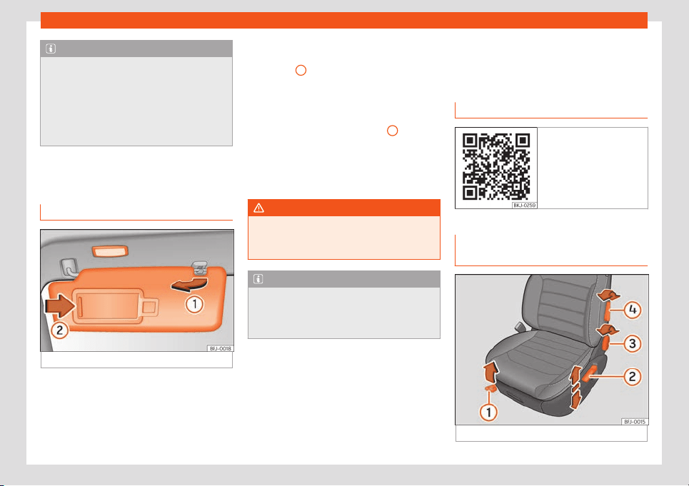
Seats and headrests
Note
●
If the electrical adjustment should fail to
operate
, both of the mirrors can be adjus-
ted by hand by lightly pressing the edge of
the mirror glass.
●
The fold-in function on the exterior mir-
rors will not activate at speeds over
40 km/h (25 mph).
Sun protection
Sun blind
Fig. 105
Sun visor
Options for adjusting driver and front pas-
senger sun visors
●
Lower the sun visor towards the wind-
scr
een.
●
The sun visor can be pulled out of its
mounting and t
urned t
o
w
ar
ds the door
›
››
Fig. 105
1
.
●
Swing the sun visor towards the door, longi-
t
udinally backw
ar
ds.
Ther
e is a v
anit
y mirr
or on the sun visor, with a
cover. When the cover is opened
2
a light
comes on.
The l
amp goes out when the v
anit
y mirr
or
co
v
er is cl
osed or the sun visor is pushed
back up.
WARNING
Folded sun blinds can reduce visibility.
●
Always store sun blinds and visors in their
housing when not in use.
Note
The light above the sun visor automatically
switches off after a few minutes in cer
tain
conditions. This prevents the battery from
discharging.
Seats and headrests
Adjusting seats
R
el
at
ed video
Fig. 106 Vehicle interior
Manual adjustment of the front
seats
Fig. 107 Front seats: manual seat settings.
»
123
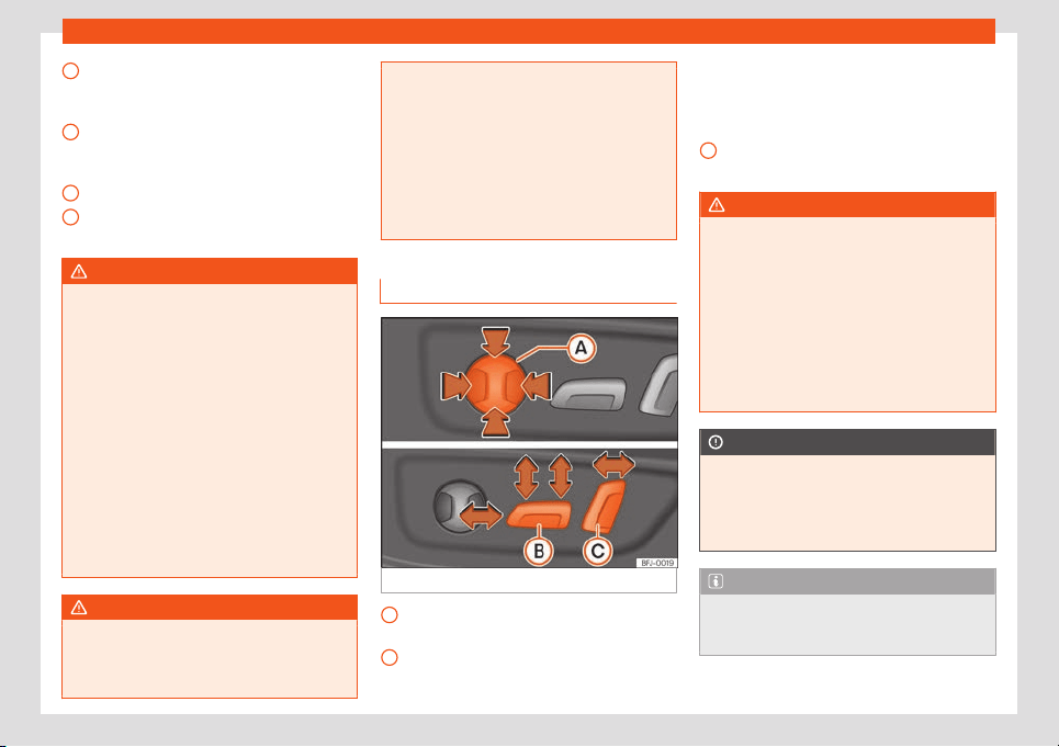
Operation
Forwards/backwards: pull the lever and
mo
v
e the seat. The seat must engage
when the l
e
v
er is r
el
eased!
Raise/lower: pull the lever up or push
down (several times if necessary) from its
home position.
Tilting the backrest: turn the hand wheel.
Lumbar support: move the lever until the
required position is achieved.
WARNING
Incorrect seat adjustment may lead to ac-
cidents and severe injuries.
●
Only adjust the seats when the vehicle is
stationary, as the seats coul
d move unex-
pectedly while the vehicle is in motion and
you could lose control of the vehicle. Fur-
thermore, an incorrect position is adopted
when adjusting the seat.
●
Adjust the height, position and inclination
of the front seats only when their move-
ment area is empty.
●
Make sure there are no objects in that
area.
●
Make sure that the movement and lock-
ing areas of the seats are clean.
WARNING
Incorrectly using upholstery and seat cov-
ers might cause an accidental activation of
the electrical seat adjustment system and
make it mov
e unexpectedly while driving.
1
2
3
4
This might cause loss of control of the vehi-
cle and thus accidents or injuries. More-
over, the electrical components of the fr
ont
seats might be damaged.
●
Never attach or place seat upholstery or
covers on the electric controls.
●
Never use upholstery or seat covers that
have not been explicitly authorised for the
seats of the vehicle.
Electric driver's seat adjustment*
Fig. 108 Driver's seat: electric seat settings.
Adjust the lumbar support: press the but-
t
on accor
ding t
o the desir
ed position.
Seat f
orw
ar
ds/backwards: press the but-
ton forwards/backwards.
A
B
Seat up/down: Press the rear part of the
butt
on up/do
wn. T
o adjust the angl
e of
the seat cushion, pr
ess the fr
ont of the
butt
on up/down.
Backrest further upright/further reclined:
press the button forwards/backwards.
WARNING
●
If the electric front seats are used negli-
gently or without paying due attention, it
can cause serious injury.
●
The front seats can also be el
ectrically
adjusted when the ignition is switched off.
Never leave a child or any other person
who may need help in the vehicle.
●
In the event of an emergency, electrical
adjustment can be stopped by pressing
any control.
CAUTION
To avoid damaging the electrical compo-
nents of the front seats, please refrain from
kneeling on the seat or applying sharp
pressur
e at a single point to the seat cush-
ion and backrest.
Note
●
It may not be possible to electrically ad-
just the seat if the vehicle battery is v
ery
low.
C
124
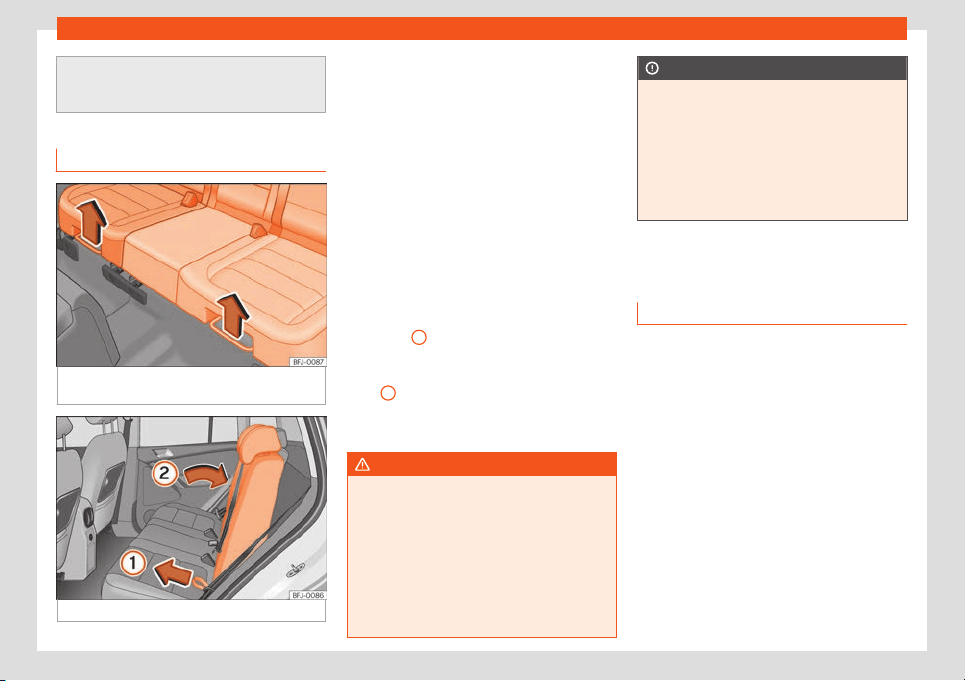
Seats and headrests
●
If the engine is started while the seats are
being electrically adjust
ed, the adjustment
will stop.
Adjusting the rear seat
Fig. 109 Under the bench of the rear seat: set-
ting l
e
v
ers.
Fig. 110 Rear seat backrest adjustment.
The rear seat is asymmetrical and each part
can be adjust
ed separ
at
ely.
Adjusting the r
ear seat
●
Pull the right of l
eft l
e
ver, in the direction of
the arrow
›››
Fig. 109, and move the part cor-
responding to the seat to the front or the
back.
●
Release the lever and lock the seat, moving
it slightly to the front or the back.
Adjusting the rear seat backrest
●
Press the right or left backrest of the seat
with one hand and, at the same time, pull
from the corresponding cord with the other
›››
Fig. 110
1
.
●
Move the backrest with your hand to the
desir
ed position; ther
e will be some r
esist
-
ance
2
.
●
Release the cord and lock the backrest,
mo
ving it slightly t
o the fr
ont or the back
.
WARNING
Incorrect backrest adjustment may lead to
accidents and severe injuries.
●
Only adjust the rear seat when the vehi-
cle is st
ationary; otherwise, it could move
unexpectedly while the vehicle is in motion.
Furthermore, an incorrect position is adop-
ted when adjusting the seat.
●
Adjust the rear seat only when its move-
ment area is empty.
CAUTION
●
When moving the rear seat horizontally,
objects in the luggage compartment might
cause damages.
●
When the seat is in its fr
ontmost position,
objects can be stored between the seat
and the luggage compartment. Before
moving the seat backwards, remove any
objects in this area.
Headrest
Intr
oduction
The possibilities for the adjustment and disas-
sembly of the headr
ests ar
e described bel
o
w
.
Al
w
ays make sure that the seats are correctly
adjusted
›››
page 12.
All seats are equipped with a headrest. The
rear headrests have been designed exclu-
sively for the corresponding seat of the sec-
ond or third row. Therefore, never mount them
on any other seat.
Correct adjustment of headrest
Adjust the headrest so that its upper edge is
at the same level as the top of your head and
under no circumstances below eye level.
Keep the back of your head always as close
to the headrest as possible.
»
125
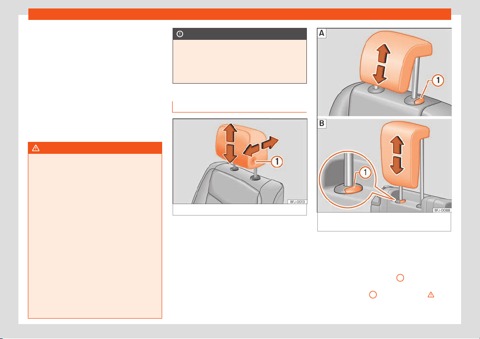
Operation
In vehicles with horizontally adjustable headr-
ests on the fr
ont seats, mo
v
e the headr
est as
cl
ose as possibl
e t
o the back of the head.
Adjusting the headrest for short people
Lower the headrest completely, even if your
head is below its upper edge. In the lowest
position, there may be a small distance be-
tween the headrest and the backrest.
Adjusting the headrest for tall people
Push the headrest up as far as it will go.
WARNING
If travelling with the headrests removed or
improperly adjusted, the risk of severe or
fat
al injuries in the event of accidents and
sudden braking or manoeuvres increases.
●
Always travel with the headrest correctly
installed and adjusted.
●
To decrease the risk of cervical injuries in
the event of an accident, adjust the head-
rest correctly based on your height, always
making sure that its upper edge is at the
same height as the top of the head, but
never below eye level. Keep the back of
your head always as close to the headrest
as possible and centred.
●
Never adjust the headrest while the vehi-
cle is in motion.
●
Under no circumstances should the rear
passengers travel while the headrests are
in the non-use position.
CAUTION
When assembling and disassembling the
headrests, do not let them meet the top lin-
ing of the vehicle, the back r
est of the front
seat or other parts of the vehicles. If not,
this could damage the vehicle.
Adjusting the headrests
Fig. 111
Front seat: headrest adjustment.
Fig. 112
Adjusting the rear headrests: Sec-
ond r
o
w of seats,
thir
d r
o
w of seats.
Adjusting the height of the headrests
●
Move the headrest up or down in the direc-
tion of the corr
esponding arr
o
w
. R
egar
ding
the r
ear headrest, to both raise and lower,
press the button
›››
Fig. 111
1
; for the rear
headr
ests it is only necessary t
o pr
ess the
butt
on
›
›
›
Fig. 112
1
to lower them
›
›
›
in
Intr
oduction on page 126
.
126
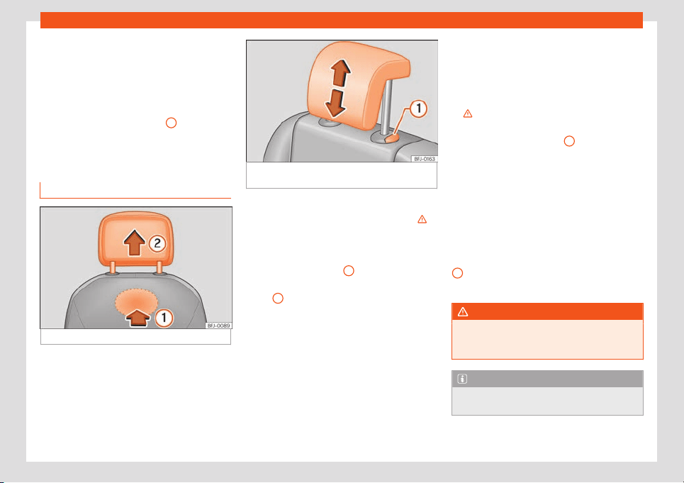
Seats and headrests
●
The headr
est must l
ock corr
ectly in one po-
sition.
Adjusting the fr
ont headr
ests horiz
ont
ally
●
Move the headrest forward or back in the
direction of the corresponding arrow while
pressing the button
›››
Fig. 111
1
.
●
The headrest must lock correctly in one po-
sition.
Removing and fitting the headrests
Fig. 113 Front headrest: removal.
Fig. 114 Removal of the rear headrests: sec-
ond row of seats.
Removing the front headrests
●
If this is the case, lower the headrest
›
›
›
in
Intr
oduction on page 126
.
●
T
o unl
ock it, l
ook f
or the r
abbet on the bot-
tom of the backrest and press in the direction
of the arrow
›››
Fig. 113
1
.
●
Remove the headrest in the direction of the
arr
o
w
2
.
Fitting the fr
ont headr
ests
●
Pl
ace the headr
est in the corr
ect position
on the guides of the corr
esponding backr
est
and insert it.
●
Press the headrest downwards until the
bars lock.
●
Adjust the headrest according to the in-
structions on the correct position of the seat.
Removing the headrests from the second
row of seats
●
If necessary, adjust the backrest of the seat
so the headrest can be removed.
●
Push the headrest up as far as it will go
›››
in Introduction on page 126.
●
Remove the headrest completely while
pr
essing butt
on
›
›
›
Fig. 1
14
1
.
Inst
alling the headr
ests of the second r
o
w
of seats
●
Unl
ock the r
ear seat backr
est and fold it
forward slightly
›››
page 125.
●
Place the headrest in the correct position
on the guides of the corresponding backrest
and insert it.
●
Lower the headrest while pressing button
1
.
●
Raise the rear seat backrest and lock it.
WARNING
Remove the rear headrests only when it is
necessary to fit a child seat. After removing
a child seat, r
efit the headrest immediately.
Note
The headrests of the third row of seats can-
not be removed.
127
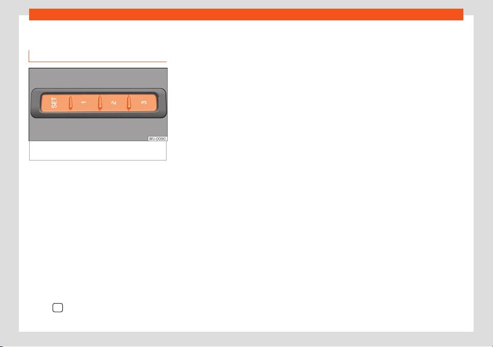
Operation
Seat functions
Memory function*
Fig. 115
On the outer side of the driver's seat:
memory butt
ons.
Memory buttons
Individual settings f
or the corr
esponding seat
can be st
or
ed with the memory butt
ons. Addi-
tionally, settings f
or the e
xterior mirrors can
be saved with the memory buttons of the
driver seat.
Save the settings of the driver seat and
the exterior mirrors while driving forward
●
Apply the electronic parking brake.
●
Move the gearshift to the neutral position.
●
Switch the ignition on.
●
Adjust the driver seat and the exterior mir-
rors.
●
Press
for longer than 1 second
›
›
›
Fig. 1
15
.
●
Pr
ess the memory butt
on in which to store
the settings within approx. 10 seconds. A
warning sound will confirm they have been
stored.
Storing the passenger rear view mirror
settings while driving in reverse
●
Apply the electronic parking brake.
●
Move the gearshift to the neutral position.
●
Switch the ignition on.
●
Press the required memory button.
●
Select reverse gear.
●
Adjust the front passenger exterior mirror so
that you can see, for example, the kerb area
well.
●
The new position of the mirror will be stored
automatically and allocated to the vehicle
key that was used to unlock the vehicle.
Activating settings
●
With the vehicle stopped and the ignition
switched on, press and hold the correspond-
ing memory button until the saved position is
reached.
●
OR: With the ignition switched off and the
driver's door open, briefly press the corre-
sponding button.
●
The front passenger side exterior mirror au-
tomatically changes from the position stored
for reversing as soon as the vehicle moves
forward at a speed of at least 15 km/h
(10 mph) or when the gear selection lever is
changed to a position other than R
›››
page 121.
To activate the memory function of the ve-
hicle key
Condition: a position must be memorised in
the memory.
●
Open the driver-side door.
●
Press and hold any memory button.
●
Within three seconds of the move being
completed, push the open button on the
vehicle key. An audible warning confirms the
settings have been activated.
Adjusting the wing mirrors for driving and
assigning driver seat settings to a vehicle
key
●
Activate the memory function of the vehicle
key
●
With the ignition switched on, adjust the ex-
terior mirrors and the seat.
●
An audible warning confirms the saved po-
sition, both when turning off the ignition and
locking the vehicle. The settings are assigned
to the vehicle key.
To deactivate the memory function of the
vehicle key
Condition: a position must be memorised in
the memory.
128
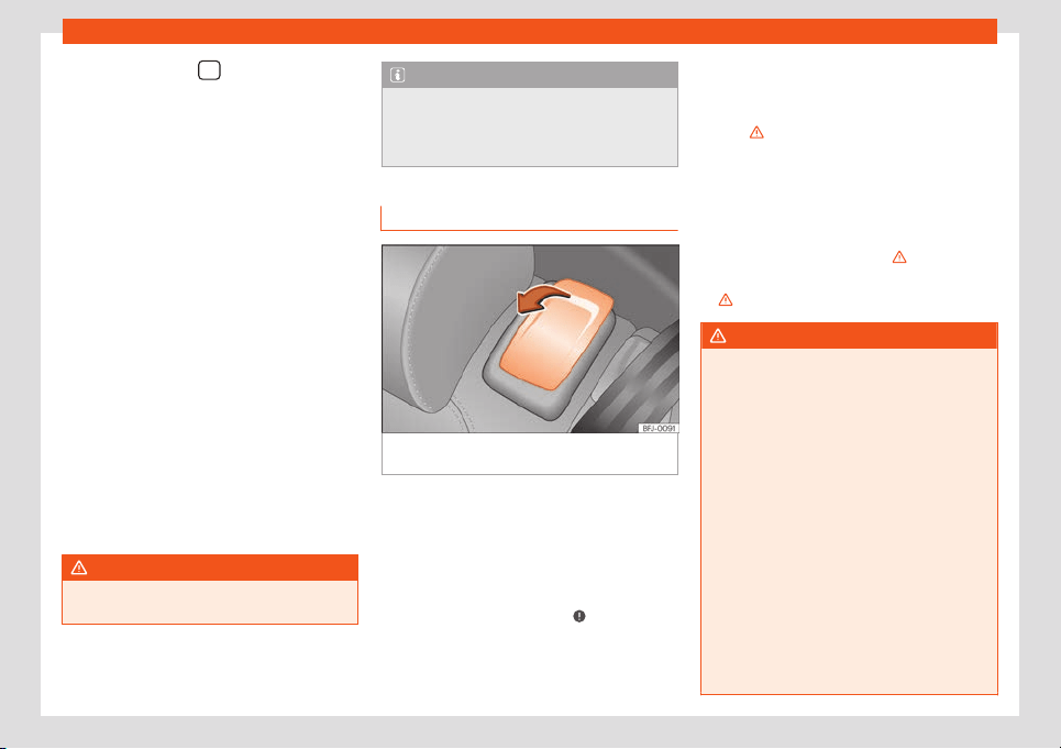
Seats and headrests
●
Pr
ess and hol
d the
button
›
›
›
Fig. 1
15
.
●
Within the f
oll
owing 10 seconds, push the
open button on the vehicle key. An audible
warning confirms the settings have been de-
activated.
Initialising the seat position memory
The position memory system must be restar-
ted if, for example, the driver seat has been
changed.
Restarting deletes all memories and assign-
ments for the seat with position memory. The
memory buttons can then be reprogrammed
and the vehicle keys re-assigned.
●
Open the driver door and do not get into
the vehicle.
●
Operating the seat settings from outside
the vehicle.
●
Move the angle of the seat backrest com-
pletely forwards.
●
Release the control to set the angle and
then press again until an audible warning is
heard.
WARNING
Adjust the memory function only when the
vehicle is stationary.
Note
If the driver door is opened approx. 10 mi-
nutes after the vehicle was unlock
ed or lat-
er, the driver seat and the exterior mirrors
do not move automatically.
Access aid for the third row of seats
Fig. 116
Second row of seats:: access aid con-
tr
ol
s.
The convenient entry function makes it easier
t
o access the thir
d r
o
w of seats.
F
ol
ding do
wn the backrest and moving the
second row seat
●
Remove any objects located in the footwell
of the second row of seats
›››
.
●
Pull the release lever
›
›
›
Fig. 1
16
in the di-
r
ection of the arr
ow.
●
Fold down the backrest of the seat and
move the seat forward.
●
Enter the vehicle or leave the vehicle care-
fully
›››
.
F
ol
ding do
wn the second r
o
w backr
est
●
Mo
ve the rear seat to its rearmost position.
●
Pull the lever
›››
Fig. 116 and push the back-
rest backwards until it is in a vertical position.
The entire seat folds down
›››
.
●
The rear seat must be correctly engaged
›
›
›
.
WARNING
If the convenient entry function is used
negligently or without due care, this may
cause accidents and serious injury.
●
Never use the convenient entry function
when the vehicl
e is in motion.
●
Avoid trapping or damaging the seat belt
when folding the rear seats back.
●
When moving the backrests up and down,
keep your hands, fingers, feet and other
body parts out of the operating area of the
hinges and the locking mechanism of the
seats.
●
Mats or other objects can be caught in
the hinges of the seat backrests or the
seats themselves. This would cause the
backrests and benches not to lock correct-
ly when moving the seats to the vertical po-
sition.
»
129

Operation
●
For the rear seat belts to offer the neces-
sary protection all the par
ts of the rear
backrest must be properly engaged verti-
cally. If someone is seated in a seat whose
backrest is not properly engaged they will
be thrown forwards, along with the back-
rest, during an accident or a sudden driving
or braking manoeuvre.
●
When a rear seat or its backrest is folded
down or not correctly engaged, do not let
anyone use that seat, not even a child.
●
When going in and out of the vehicle,
never lean on or grab the tilted seat of the
second row.
WARNING
If all the seats on the second row are
equipped with child seats, in the event of
an accident the seats of the second row
cannot be pushed forw
ards from the third.
People travelling in the third row will not be
able to leave the vehicle or help them-
selves in the event of an emergency.
●
Whenever there are people in the third
row, do not install child seats on all the
second row seats at the same time.
CAUTION
Before lowering and raising the rear seat
backrest, adjust the front seats so that nei-
ther the headrests nor the cushions of the
rear backrest can hit them.
CAUTION
Any objects located in the footwell of the
second row of seats may be damaged on
folding the rear seat forw
ards. Before fold-
ing down the seats, remove the objects.
Adjusting or folding the backrest of
the front passenger seat
Fig. 117 Front passenger seat: fold the back-
r
est of the seat f
orw
ar
ds.
Fig. 118 Unlocking the folding backrest of the
front passenger seat
Adjusting the inclination of the front pas-
senger seat backr
est
●
Mo
v
e the l
e
v
er in the dir
ection of the arrow
›››
Fig. 117
1
, and adjust the backrest to the
desir
ed position.
F
ol
ding the backr
est of the fr
ont passen-
ger seat f
orw
ard
●
Remove any objects from the front passen-
ger seat cushion
›››
.
●
Move the passenger seat to its lowest posi-
tion.
●
Move the front passenger seat back as far
as possibl
e
.
●
L
o
w
er the headr
est pr
operly.
●
Unlock the backrest of the front passenger
seat in the direction of the arrow
1
.
130

Seats and headrests
●
F
ol
d the backr
est of the fr
ont passenger
seat f
orw
ar
ds in the direction of the arrow
2
until it is horizontal.
●
Once folded down, the backrest has to be
l
ock
ed saf
ely.
When carrying ob
jects on the f
ol
ded do
wn
backrest of the passenger seat, the front air-
bag of this seat must be disabled
›››
page 27.
Lifting the backrest of the front passenger
seat
●
When lifting the passenger backrest, make
sure there are no objects or body parts within
the hinge movement area.
●
Lift the backrest of the front passenger seat
by first unlocking it again
›››
Fig. 118.
●
Lift the backrest of the seat in an upright
position.
●
Once it is raised again, the backrest must
be correctly engaged.
WARNING
Serious injuries can be caused if the pas-
senger seat backrest is lowered or lifted
without due car
e and attention.
●
Only fold and lift the backrest of the front
passenger seat when the vehicle is station-
ary.
●
When folding down the passenger seat,
always make sure there are no people or
animals in the backrest area.
●
While the passenger backrest is down,
the front airbag must always be disabl
ed
and the PASSENGER AIR BAG warning
lamp must be on.
●
When moving the passenger backrest up
and down, keep your hands, fingers, feet
and other body parts out of the operating
area of the hinges and the locking mecha-
nism of the seat.
●
Mats or other objects can be caught in
the hinges of the backrest of the front pas-
senger seat. This would cause the backrest
not to be locked in an upright position when
lifting it.
●
Once the backrest is up, it must be cor-
rectly engaged in an upright position. Oth-
erwise, it could move unexpectedly and
cause severe injuries.
WARNING
When folding down the passenger back-
rest, its anchor points and hinges are left
uncovered and may cause se
vere injuries in
the event of a sudden brake or accident.
●
When the passenger seat backrest is
lowered nobody else can travel in the cor-
responding seats (not even a child).
●
When the passenger seat backrest is
lowered, the only permitted seat is the rear
seat behind the driver seat. This also ap-
plies to children travelling on a child seat.
Folding down and raising the rear
seat backr
est
Fig. 119
Folding down and lifting the rear seat
backr
est
Fig. 120 In the luggage compartment: levers
f
or r
el
ease
, fr
om the luggage compartment, of
the l
eft part
1
and right part
2
of the rear
seat backr
est.
»
131
Operation
The rear seat backrest is split and each part
can be l
o
w
er
ed f
orw
ar
d separately to extend
the luggage compartment.
Fold the backrest of the rear seat for-
wards .
●
Push the headrest down as far as it will go
›››
page 125.
●
Move the rear seat to its rearmost position.
●
If required, lower the folding table.
●
Pull the cord
›››
Fig. 119 forward in the di-
rection of the arrow while holding the seat
backrest and move it forward slowly
›››
.
●
Press the backrest down with your hand un-
til it l
ocks.
F
ol
ding do
wn the backr
est fr
om the boot
with the unl
ocking levers
●
Push the headrest down as far as it will go
›››
page 125.
●
Open the rear lid
›››
page 100.
●
Pull the unlocking lever
›››
Fig. 120 of the
part of the backrest to fold down.
●
The part of the backrest in question unlocks
and can be folded down.
●
If necessary, close the rear lid
›››
page 100.
Folding up the rear seat backrest
●
Unlock the seat backrest with the cord. The
backrest disengages from its position.
●
Without letting go of the cord, lift the back-
rest.
●
Make sure that the seat belt is not trapped.
●
Press the backrest firmly into the lock until it
engages
›››
.
●
The backrest must be properly engaged.
●
If necessary, adjust the backrest.
●
If necessary, adjust the headrest.
WARNING
Serious injuries can be caused if the rear
seat backrest is lowered or lifted without
due car
e and attention.
●
When folding down the rear seat, always
make sure there are no people or animals in
the backrest area.
●
Never lower or lift the rear seat backrest
while driving.
●
Do no trap or damage the seat belt when
raising the rear seat backrest.
●
When lowering or lifting the rear seat
backrest, keep your hands, fingers, feet
and other body parts out of its path.
●
For the rear seat belts to offer the neces-
sary protection all the parts of the rear
backrest must be properly engaged. This is
particularly important in the case of the
centre rear seat. If someone is seated in a
seat whose backrest is not properly engag-
ed they will be thrown forwards, along with
the backrest, during an accident or a sud-
den driving or braking manoeuvre.
●
When the rear seat backrest is lowered or
is not pr
operly engaged nobody else can
travel in the corresponding seats (not even
a child).
CAUTION
Serious damage can be caused to the vehi-
cl
e and other objects if the rear seat back-
rest is lo
wered or lifted without due care
and attention.
●
Before folding the rear seat backrest for-
ward, always adjust the front seats so that
neither the headrests nor the cushions of
the rear backrest can hit them.
●
Before folding the rear seat backrest, al-
ways make sure there are no objects in the
movement area of the backrest.
132

Seats and headrests
Central armrests
Fig. 121
Front centre armrest
Fig. 122
Folding rear centre armrest.
Front centre armrest
T
o
lift
the centr
al armr
est, lift it up
w
ards in the
direction of the arrow
›››
Fig. 121, setting by
setting.
To lower the armrest, first lift it to its highest
position. Then lower it down.
To move the armrest horizontally, move it for-
ward
›››
Fig. 121 or backward as much as
possible in the direction of the corresponding
arrow.
Rear centre armrest
Depending on the features, there might be a
folding armrest in the rear centre seat.
To lower the armrest, pull the cord in the di-
rection of the arrow
›››
Fig. 122.
To lift the armrest, press it down in the oppo-
site direction to the arrow
›››
Fig. 122 and lock
it in the seat backrest.
WARNING
The front centre armrest may obstruct the
driver's arm movements, which could
cause an accident and sev
ere injuries.
●
Keep the storage compartments of the
centre armrest closed at all times while the
vehicle is in motion.
●
Never let anyone sit on the centre arm-
rest while the vehicle is in motion, not even
a child. This position is incorrect and may
cause severe injuries.
WARNING
To decrease the risk of injuries while driv-
ing, the rear centre armrest must always be
raised.
●
When the centre armrest is down, nobody
may travel in the centre r
ear seat, not even
a child. An incorrect sitting position may
cause severe injuries.
133

Operation
Transport and practical
equipment
St
oring ob
jects
P
ositioning the luggage and car
go
It is possible to carry objects and luggage in
the vehicle, in a trailer
››
›
page 332 and on
the roof
›››
page 143. When doing so, please
consider all legal provisions.
Placing luggage inside the vehicle safely
●
Distribute the load in the vehicle as evenly
as possible.
●
Always place equipment and heavy ob-
jects in the boot
››
›
.
●
Position heavy items in the boot as far for-
w
ar
d as possibl
e
.
●
T
ak
e int
o account the maximum authorised
weight per axle, as well as the maximum au-
thorised weight of the vehicle
›››
page 389.
●
Secure the objects to the fastening rings of
the boot using appropriate chains or belts
›››
page 139.
●
Also place small objects safely.
●
If required. raise the rear seat backrest and
lock it.
●
Adapt tyre pressure to the load. Take into
account the pressure adhesive of the tyres
›››
page 365.
●
In vehicles equipped with tyre control sys-
tem, adjust to the new load status if necessa-
ry
›››
page 369.
WARNING
Loose or unsecured objects can cause seri-
ous injury in case of sudden manoeuvring
or braking or in case of an accident. Partic-
ularly if the airbag hits them when deploy-
ing and they are thr
own across the inside of
the vehicle. Please observe the following
rules to minimise the risk of injury:
●
Place all objects inside the vehicle safe-
ly.
●
Secure all objects, little and large.
●
Place the objects in the cabin in such a
way that they can never reach the airbag
deployment areas while the vehicle is in
motion.
●
Keep the storage compartments closed
at all times while the vehicle is in motion.
●
Place the objects in such a way that they
never force any occupant of the vehicle to
sit in an incorrect position.
●
When transporting objects that take up a
seat, never let anyone use that seat.
●
Never leave hard, sharp or heavy objects
loose in open storage compartment of the
vehicle, on the cover behind the rear seat
or on the dashboard.
●
Remove all hard, sharp or heavy objects
from the f
abrics and bags inside the cabin
and store them safely.
WARNING
The transport of heavy object changes ve-
hicl
e handling and increases braking dis-
tance. Heavy objects that ar
e not properly
placed or secured may cause loss of con-
trol of the vehicle and thus severe injuries.
●
Never put too much load in the vehicle.
Both the carrying capacity as well as the
distribution of the load in the vehicle have
effects on the driving behaviour and brak-
ing ability.
●
When transporting heavy objects, the
driving behaviour of the vehicle varies due
to the displacement of the centre of gravi-
ty.
●
Always distribute the load in the vehicle
as evenly and horizontally as possible.
●
Always place heavy objects in the boot
before the rear axle and as far away from it
as possible.
●
Objects in the luggage compartment
that are unsecured could move suddenly
and modify the handling of the vehicle.
●
Adapt your speed and driving style at all
times to suit visibility, weather, road and
traffic conditions.
●
Accelerate with particular care and cau-
tion.
134

Transport and practical equipment
●
Avoid sudden braking and manoeuvres.
●
Brake earlier than usual.
WARNING
●
Ne
ver leave your vehicle unatt
ended, es-
pecially when the rear lid is open. Children
could climb into the luggage compartment,
closing the door behind them; they will be
trapped and run the risk of death.
●
Close and lock all the doors and the rear
lid when you leave the vehicle. Before you
lock the vehicle, make sure that there are
no adults or children in the vehicle.
CAUTION
Electrical wires or, depending on the fea-
tures, the antenna embedded into the rear
windows coul
d be damaged, even irrepara-
bly, if they are in contact with objects.
Note
Straps for securing the load to the fasten-
ing rings are commercially available from
accessory shops.
Luggage compartment
L
uggage compar
tment shelf
Fig. 123 In the luggage compartment: lug-
gage compartment shelf cl
osed.
Fig. 124
In the luggage compartment: remove
the r
ear shelf
.
Open the rear shelf
●
Pull the cover backwards with the handle
›
›
›
Fig. 123
1
and remove it above the an-
chor point (arrows). Move the cover forward
car
efully.
Cl
ose the r
ear shelf
●
Pull the co
v
er backw
ar
ds with the handle
1
and secure it to the anchor point (arrows).
R
emo
v
e the r
ear shelf
●
If r
equir
ed, open the r
ear shelf.
●
Press the support of the cover
›››
Fig. 124
1
in the direction of the arrow and hold it in
this position.
●
Then lift the cover out.
●
Remove the cover support
›
›
›
Fig. 12
4
1
.
Depending on the equipment, once the lug-
gage compartment shelf has been r
emo
v
ed,
it can be st
or
ed under the boot's fl
oor
›
››
page 136.
Fit the rear shelf
●
Place the left side of the rear shelf in the
housing provided in the left side cover.
●
Press the support of the cover
›››
Fig. 124
1
in the direction of the arrow and hold it in
this position.
●
Place the cover in the housing provided in
the l
eft side co
v
er
.
●
R
emo
v
e the cover support
›››
Fig. 124
1
.
●
Check that the cover is correctly secured.
»
135
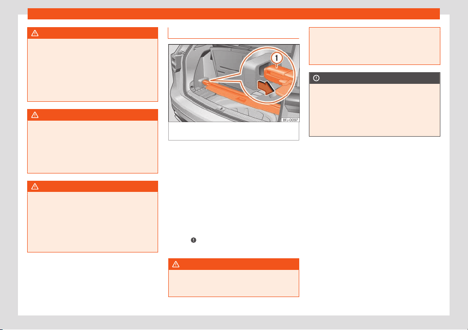
Operation
WARNING
Animals, loose or unsecured or objects car-
ried on the rear shelf can cause serious in-
jury in case of sudden manoeuvring or
braking or in case of an accident.
●
Do not leave hard, sharp or heavy ob-
jects or in bags on the rear shelf
.
●
Never transport animals on the rear shelf.
WARNING
If the rear shelf is fitted in front of a rear
seat, it may cause severe injuries in the
event of sudden braking or in the e
vent of
an accident.
●
If the seats of the third row are occupied,
never fit the rear shelf before that row.
WARNING
If driving without the covers of the rear
shelf installed, serious injury may happen
in case of sudden manoeuvring or braking
or in case of an accident.
●
In vehicles with 7 seats, alw
ays place the
covers on the housings of the rear shelf
when it is not fitted.
Store the rear shelf
Fig. 125 Below the luggage compartment
fl
oor: st
or
e the r
ear shelf
.
Depending on the equipment, once the lug-
gage compartment shelf has been r
emo
v
ed,
it can be st
or
ed under the boot fl
oor
.
●
Lift the floor of the boot
›››
page 138.
●
Place the rear shelf in the corresponding
housing
›››
Fig. 125.
●
Place the boot floor in its starting position.
If the 12-volt battery is fitted in the boot, do
not store the rear shelf under the boot
floor
›››
. If you are going to use the third row
of seats, k
eep the co
v
er at home
.
WARNING
During a sudden driving or braking ma-
noeuvre, or in the event of an accident, ob-
jects could be flung though the interior and
cause serious or fatal injuries or damage to
the vehicle.
●
Never leav
e the rear shelf loose in the
luggage compartment.
CAUTION
If the rear shelf is stored incorrectly, it may
cause damages t
o the electrical system or
the cabin.
●
When storing the rear shelf, al
ways make
sure it does not touch the 12-volt battery in
the boot.
136
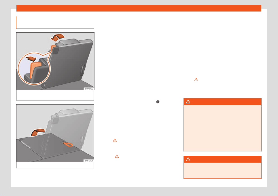
Transport and practical equipment
Placing the third row of seats in the
car
go fl
oor position
Fig. 126
Third row of seats: place in the cargo
fl
oor position.
Fig. 127 Third row of seats: lift the seat.
The rear seats can be folded down separate-
ly t
o e
xt
end the boot.
Pl
acing the thir
d r
o
w of seats in loading
floor position
●
Disassemble the luggage compartment
tray
›››
page 135.
●
Push the headrest down as far as it will go
›››
page 125.
●
Release the seat belt from both locks to
prevent damages to the seat and the seat
belt.
●
Fold down the folding tables on the front
seats.
●
Move the seats of the second row com-
pletely forward
›››
page 125.
●
Open the rear lid
›››
page 100.
●
Remove any objects located in the footwell
in front of and behind the seat
›››
.
●
Remove objects from the space below the
corr
esponding seat.
●
Pull the unl
ocking l
e
v
er
›
›
›
Fig. 126 to its
rearmost position to unlock the seat backrest.
●
Move the seat down with your hand until it
is completely against the frame of the
seat
›››
.
●
When the seat is in loading floor position,
do not et anyone tr
av
el in it (not e
v
en a
chil
d)
›
›
›
.
●
Close the tailgate.
Lifting the seats of the third row
●
Move the seats of the second row com-
pl
et
ely f
orw
ar
d
›
›
›
page 125.
●
Open the rear lid.
●
Pull the cord on the backrest of the seat
›››
Fig. 126 to lift the backrest. OR: lift the
backrest with your hand from the cabin.
●
The red marking on the unlock lever
›››
Fig. 126 must not be seen.
●
Make sure that the seat backrest is correct-
ly engaged by tugging from it and press-
ing
›››
.
●
If required, fit the rear shelf again.
●
Close the tailgate.
WARNING
Risk of suffering severe head injuries If peo-
ple taller than 1.60 m travel in the thir
d row,
they may receive severe head injuries in
the event of an accident.
●
Never travel with anyone taller than 1.60
m on the third row.
●
When closing the rear lid, always be
mindful of the passengers of the rearmost
seats.
WARNING
If the rear seats are folded down or lifted
without paying attention or without control,
severe injuries might occur.
»
137
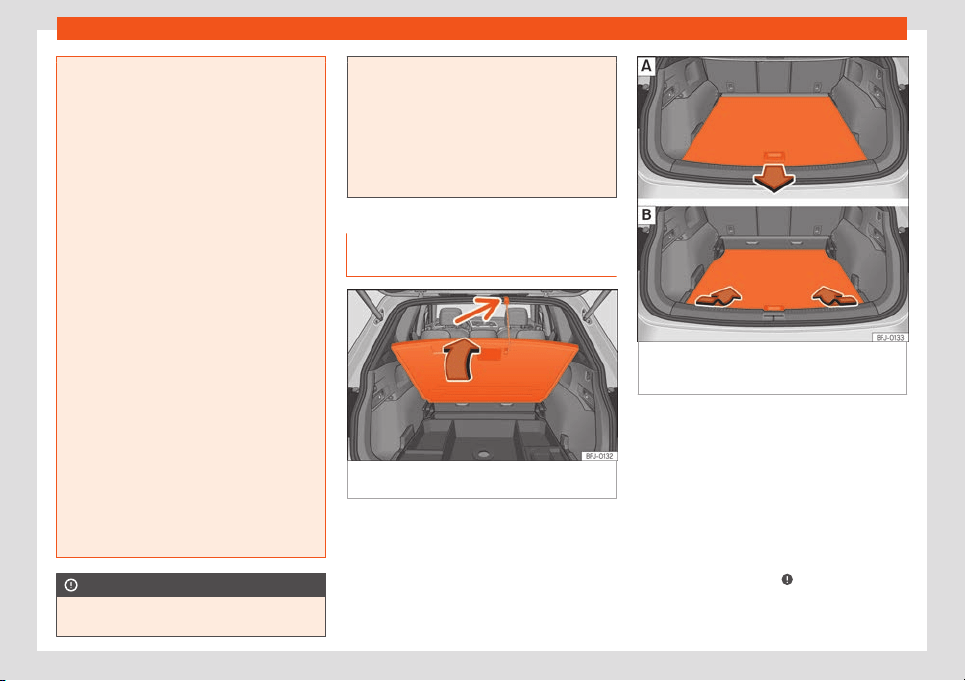
Operation
●
Never lower or lift the rear seat backr
ests
while driving.
●
Do no trap or damage the seat belt when
raising the rear seat backrests.
●
When moving the rear seat backrests up
and down, keep your hands, fingers, feet
and other body parts out of the operating
area of the hinges and the locking mecha-
nism of the seats.
●
Mats or other objects can be caught in
the hinges of the seat backrests or the
seats themselves. This would cause the
backrests not to be locked correctly in an
upright position.
●
For the rear seat belts to offer the neces-
sary protection, the rear backrests must be
properly engaged vertically. If someone is
seated in a seat whose backrest is not
properly engaged they will be thrown for-
wards, along with the backrest, during an
accident or a sudden driving or braking
manoeuvre.
●
A red mark on unlock lever
›››
Fig. 126 in-
dicates that the seat backrest is not en-
gaged. If the back rest is locked correctly,
the mark is not visible.
●
When a rear seat or its backrest is folded
down or not correctly engaged, do not let
anyone use that seat (not even a child).
CAUTION
●
Objects placed in the footwell in front of
and behind the rear seats can be damaged
when seats are folded down or lifted. Be-
fore folding down or lifting the seats, re-
mo
ve the objects.
●
Any objects located in the footwell be-
hind the third row of seats may be dam-
aged on folding or lifting the seats of this
row. Before folding down or lifting the seats,
remove the objects.
Adjustable luggage compartment
floor (5-seater vehicles)
Fig. 128 In the luggage compartment: lift the
luggage compartment fl
oor
.
Fig. 129
In the luggage compartment: adjust
the height of the v
ariabl
e luggage compart
-
ment fl
oor
.
Open boot floor
●
Grab the boot floor by the opening
›
›
›
Fig. 128
and lift it in the dir
ection of the ar
-
r
ow. Secure the belt to the rubber gasket
(small arrow).
Close boot floor
●
Loosen the belt and secure it to the support
under the boot floor. Move the floor down
carefully and let it go
›››
.
138
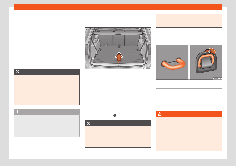
Transport and practical equipment
Adjust the height of the variable boot floor
Depending on the f
eat
ur
es, the height of the
boot fl
oor can be adjust
ed.
●
If necessary, r
el
ease the net bag
›››
page 140 and, if necessary, remove the
belts.
●
Lift the boot floor and pull it backwards to
release it from the side guides of the boot
›››
Fig. 129 .
●
Place the floor on the guides of the desired
height and move it forwards
›››
Fig. 129 .
CAUTION
●
Do not tug the boot floor suddenly when
opening or let it fall down when closing.
Otherwise
, the lining and the floor of the
boot could be damaged.
●
The maximum weight that can be loaded
on the luggage compartment variable floor
in the top position is 125 kg.
Note
●
Depending on the features, there are
stor
age compartments for small objects
under the boot floor.
●
SEAT recommends the use of fastening
straps to secure objects to retaining rings.
Luggage compartment floor (7-
seat
er v
ehicl
es)
Fig. 130
In the luggage compartment: lift the
luggage compartment fl
oor
.
Open boot floor
●
Grab the boot floor by the cord
›
›
›
Fig. 130
and lift it in the dir
ection of the arr
o
w and r
e-
move it.
Close boot floor
●
Place the boot floor on the support and
carefully lower it
›››
.
CAUTION
●
Do not let the luggage compartment
floor fall when closing it. Alw
ays carefully
guide it downward in a controlled manner.
Otherwise, the lining and the floor of the
boot could be damaged.
●
The maximum weight that can be loaded
on the luggage compartment variable floor
in the t
op position is 125 kg.
Fastening rings
Fig. 131
In the luggage compartment: fixed
and depl
oyabl
e f
ast
ening rings.
There are fastening rings
›
›
›
Fig. 131
on the
fr
ont and r
ear of the boot t
o secure loose ob-
jects and luggage with fastening belts and
cords.
WARNING
If unsuitable or damaged belts or retaining
straps are used, they could break in the
event of br
aking or an accident. Objects
could then be launched across the passen-
ger compartment and cause serious or fa-
tal injuries.
●
Always use belts or straps that are suita-
ble and in good condition.
»
139
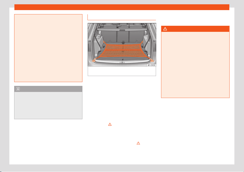
Operation
●
Tighten the belts and straps in a cross
layout over the l
oad placed on the boot
floor and secure them to the fastening rings
safely.
●
Never exceed the maximum tensile load
of the fastening rings when securing ob-
jects.
●
Make sure that, particularly for flat ob-
jects, the upper edge of the load is higher
than the fastening rings.
●
Depending on the features, take into ac-
count the instruction panels on the boot on
how to place the load.
●
Never secure a child seat to the fastening
rings.
Note
●
The maximum tensile load that the fas-
tening rings can support is appr
ox. 3.5 kN.
●
Belts, straps and securing systems for the
appropriate load can be obtained from
specialised dealerships. SEAT recom-
mends visiting a SEAT dealership for this.
Net bag*
Fig. 132
In the luggage compartment: net bag
hook
ed up at fl
oor l
e
v
el
.
The luggage compartment prevents light
luggage fr
om mo
ving. The net bag has a zip
and can be used t
o st
or
e small ob
jects.
Hooking the net bag int
o the luggage
compartment floor
If necessary, the front eyes must be unfolded
first
›››
page 139.
●
Secure the net hooks to the fastening rings
›››
Fig. 132
›››
. The bag zip should be facing
up
w
ar
ds.
R
emo
ving the net bag
The hook
ed up net bag is t
aut
›››
.
●
Release the net bag from the fastening
rings.
●
St
or
e the net bag in the luggage compart
-
ment.
WARNING
To secure the elastic net bag on the fasten-
ing rings of the boot it must be stretched
out. Once hooked up it is taut. If the net bag
is hooked up or unhooked incorr
ectly the
hooks could cause injuries.
●
Always secure the bag hooks properly so
that they do not suddenly release from the
fastening rings when hooking or unhooking
them.
●
On hooking or unhooking them, protect
your eyes and face in case the hooks are
released suddenly.
●
Always hook up the net bag hooks in the
described order. If a hook is unfastened
suddenly, this may cause injuries.
140
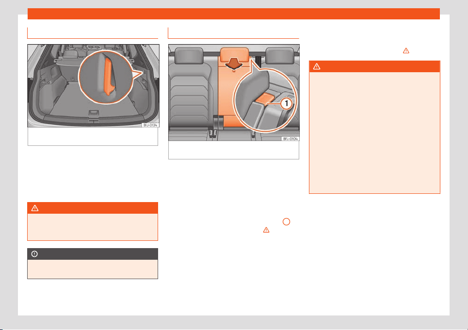
Transport and practical equipment
Bag hooks
Fig. 133
In the luggage compartment: bag
hooks.
There may be hooks for hanging bags on
both sides of the luggage compartment
›
›
›
Fig. 133
.
The r
et
aining hooks hav
e been designed to
secure light shopping bags.
WARNING
Never use the hooks to hang luggage or
other objects. In case of sudden braking or
an accident, the hooks could break.
CAUTION
Each hook is designed for a maximum load
of 2.5 kg.
Trapdoor for long loads
Fig. 134
Backrest of the rear seat: opening the
tr
apdoor f
or l
ong l
oads
Depending on the features, on the rear seat,
behind the centr
al armr
est, ther
e is a t
ail
-
boar
d f
or transporting long items in the interi-
or, such as skis.
Opening the tailboard for long items
●
Press the unlocking button
›››
Fig. 134
1
and fold the tailboard forward
›
›
›
.
●
Open the rear lid.
●
Insert the long objects through the tail-
boar
d fr
om the luggage compartment.
●
Secur
e the ob
jects with the seat belt firmly.
●
Cl
ose the t
ail
gate.
Closing the tailboard for long items
●
Lift the seat back and press it firmly into the
lock until it engages correctly
›››
.
WARNING
Serious injuries can be caused if the tail-
board for long items is low
ered or lifted
without due care and attention.
●
Never lower or lift the tailboard while
driving.
●
Do no trap or damage the seat belt when
raising the tailboard.
●
When lowering or lifting the tailboard,
keep your hands, fingers, feet and other
body parts out of its path.
●
When the tailboard is lowered or is not
properly engaged nobody else can travel
in the corresponding seats, particularly
children.
141
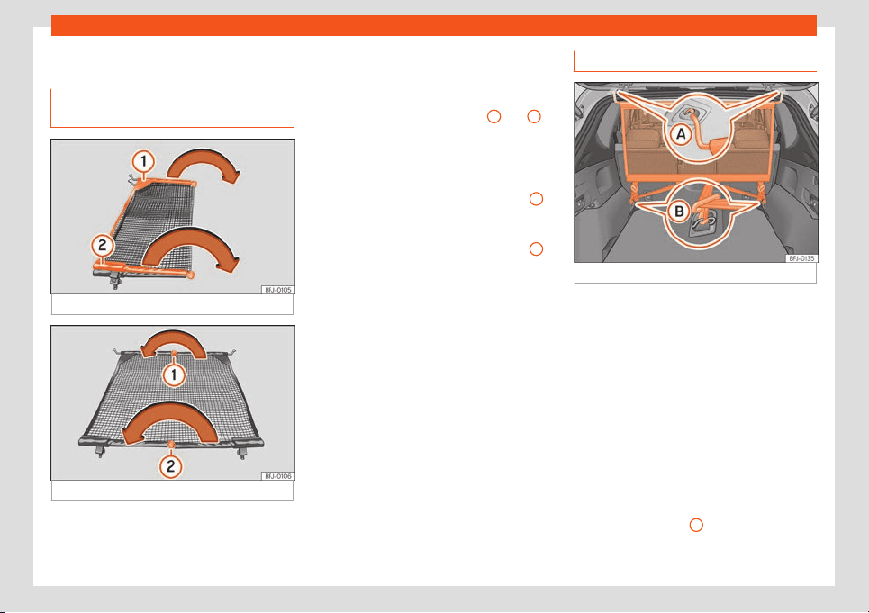
Operation
Net partition*
Unf
ol
ding and f
ol
ding the net par
ti-
tion
Fig. 135
Deploying the net partition.
Fig. 136
Folding in the net partition.
Before fitting the net partition in the vehicle it
must be unf
ol
ded.
F
ol
d out the net par
tition
T
ak
e out the partition net from the corre-
sponding bag and unroll it.
Extend the cross rods
›››
Fig. 135
1
and
2
of
the net in the dir
ection of the arr
o
ws until it
“clicks”.
F
ol
ding in the net par
tition
●
Pr
ess on the release button
›››
Fig. 136
1
and bend the cross rod in the direction of the
arr
o
w with the butt
on pr
essed.
●
Pr
ess on the r
el
ease button
›››
Fig. 136
2
and bend the cross rod in the direction of the
arr
o
w with the butt
on pr
essed.
●
F
ol
d in the net partition and st
ore it in its
bag.
●
Store the net partition safely in the vehicle.
Using the net partition
Fig. 137
Net partition fitted.
The purpose of the net partition is to prevent
the it
ems in the boot fr
om mo
ving int
o the
cabin, e
.g. in the e
v
ent of sudden braking.
Fitting the net partition
The partition net can be fitted behind the rear
seat or, depending on the features, behind
the front seats with the second row of seats
lowered.
●
If required, remove the rear shelf
›››
page 135.
●
Folding out the net partition
›››
page 142.
●
Secure the net partition in the left housing
of the roof
›››
Fig. 137
A
. Make sure to move
the cr
oss r
od do
wn beyond the upper posi-
tion.
14
2
Transport and practical equipment
●
Hook in the net partition on the r
ear right
-
hand side r
oof housing by pr
essing on the r
od
›
›
›
Fig. 137
A
.
●
Secure two hooks of the partition net to the
f
ast
ening rings of the boot
›
›
›
Fig. 137
B
and
tight
en the str
aps firmly.
R
emo
ving the net par
tition
●
If r
equir
ed, remove the rear shelf
›››
page 135.
●
Loosen the straps from the net partition.
●
Release the net hooks from the fastening
rings
›››
Fig. 137
B
.
●
Unhook the net partition on the right-hand
side r
oof support
›
›
›
Fig. 137
A
by pressing
on the r
od.
●
Unhook the net partition fr
om the l
eft
-hand
side r
oof housing.
●
F
ol
d in the net partition
›››
page 142.
●
If required, fit the rear shelf
›››
page 135.
WARNING
In order to ensure the proper functioning of
the luggage restraint systems (backrests
together with the net partition), pl
ace the
second row of seats in their rearmost posi-
tion to avoid the possibility of the load on
top moving forward. Risk to vehicle occu-
pants.
WARNING
During a sudden driving or braking ma-
noeuvre, or in the event of an accident, ob-
jects could be flung though the interior and
cause serious or f
atal injuries.
●
Check whether the cross rods are cor-
rectly engaged.
●
Always secure objects, even when the
net partition is properly assembled.
●
There should be nobody behind the net
partition when the vehicle is moving.
CAUTION
If the net partition is secured incorrectly or
to incorrect points, this may damage the
vehicle.
Roof carrier*
Intr
oduction
The vehicle roof has been designed to opti-
mise aer
odynamics. F
or this r
eason, cr
oss
bars or conv
entional r
oof carrier syst
ems
cannot be secured to the roof water drains.
As the roof water drains are integrated in the
roof to reduce air resistance, only SEAT-ap-
proved cross bars and roof carrier systems
can be used.
Cases in which cross bars and the roof
carrier system should be disassembled.
●
When they are not used.
●
When the vehicle is washed in a car wash.
●
When the vehicle height exceeds the maxi-
mum height, for example, in some garages.
WARNING
●
Always secure the load properly using
belts or ret
aining straps that are suitable
and in a good condition.
●
Bulky, heavy, long or flat loads have a
negative effect on aerodynamics, the cen-
tre of gravity and driving performance.
●
Avoid sudden braking and manoeuvres.
●
Adapt your speed and driving style at all
times to suit visibility, weather, road and
traffic conditions.
CAUTION
●
Remove the cross bars and the roof carri-
er system bef
ore entering a car wash.
●
Vehicle height is increased by the instal-
lation of cross bars or a roof carrier system
and the load secured on them. For this pur-
pose, check that your vehicle's height does
not surpass the headspace limit, for exam-
ple, for underpasses or for entering garage
doors.
»
143
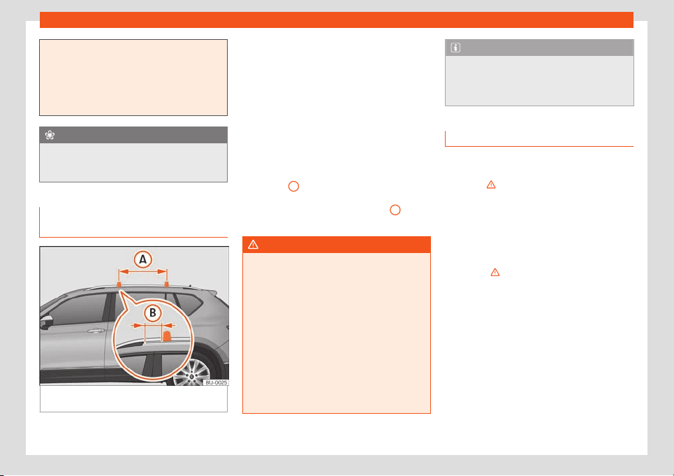
Operation
●
Cross bars, the roof carrier system and
the load secured on them should not int
er-
fere with the roof aerial or hamper the path
of the panoramic sun roof and the rear lid.
●
On opening the rear lid make sure that it
does not knock into the roof load.
For the sake of the environment
When cross bars and a roof carrier system
ar
e installed, the increased air resistance
means that the v
ehicle uses more fuel.
Securing the crossbars and the
r
oof carrier syst
em
Fig. 138
Attachment points for the roof railings
f
or the r
oof carrier syst
em.
The crossbars are the basis of a series of
special r
oof carrier syst
ems. F
or saf
et
y r
ea-
sons, special fixt
ures must be used to safely
transport luggage, bicycles, skis, surf boards
or boats on the roof. Suitable accessories
can be acquired at SEAT dealerships.
Always secure the crossbars and the roof
carrier system properly. Always take the as-
sembly instructions that come with the cross-
bars and the roof carrier system in question
into account.
The crossbars are assembled on the roof rail-
ings. The distance between crossbars
›››
Fig. 138
A
should be between 75 and 90
cm and the dist
ance betw
een the cr
ossbars
and the br
ack
ets of the r
oof r
ailings
B
must
be 15 cm.
WARNING
Incorrect attachment and use of the cross-
bars and the roof carrier system may cause
the whole system to detach fr
om the roof
and cause an accident and injuries.
●
Always take the manufacturer assembly
instructions into account.
●
Check threaded joints and attachments
travelling and if necessary tighten them af-
ter you have travelled a short distance.
When making long trips, check the threa-
ded joints whenever you stop for a rest.
●
Do not modify or repair the crossbars or
roof carrier system.
Note
Always read the assembly instructions that
come with the crossbars and the roof carri-
er system carefully and keep them in the
vehicl
e.
Loading the roof carrier system
The load can only be secured if the crossbars
and the roof carrier system are properly in-
stalled
›
››
.
Maximum authorised car
go on the r
oof
The maximum authorised car
go permitt
ed t
o
be tr
ansport on the r
oof is 75 kg. This figure
comes from the combined weight of the roof
carrier, the cross bars and the load itself on
the roof
›››
.
Al
w
ays check the w
eight of the r
oof carrier
syst
em, the cr
oss bars and the w
eight of the
load to be transported and weigh them if
necessary. Never exceed the maximum au-
thorised roof load.
If you are using cross bars and a roof carrier
with a lower weight rating, you will not be
able to carry the maximum authorised roof
load. In this case, do not exceed the maxi-
mum weight limit for the roof carrier which is
listed in the fitting instructions.
144
Transport and practical equipment
Distributing a load
Distribut
e l
oads unif
ormly and secur
e them
corr
ectly
›
›
›
.
Check att
achments
Once the cr
oss bars and r
oof carrier syst
em
hav
e been inst
all
ed, check the bolted con-
nections and attachments after a short jour-
ney and subsequently with a certain frequen-
cy.
WARNING
●
Never exceed the maximum authorised
load on the roof and on the axl
es or the ve-
hicle's maximum authorised weight.
●
Never exceed the load capacity of the
cross bars and the roof carrier system,
even if the maximum authorised roof load
has not been reached.
●
Secure heavy items as far forward as
possible and distribute the vehicle load
uniformly.
WARNING
If the load is loose or not secured, it could
fall from the roof carrier system or cause
accidents and injuries.
●
Always use belts or r
etaining straps that
are suitable and in a good condition.
Storage compartment
Intr
oduction
Use the storage compartments only for small
or light items.
The Apple
®
iPod adapter, the
USB port or
the multimedia jack (AUX-IN) are housed in
the storage compartment of the front central
armrest.
WARNING
Objects inside the vehicle that are not se-
cured could be thrown across the cabin in
the ev
ent of sudden braking or manoeu-
vring. This may cause severe injuries as
well as loss of control of the vehicle.
●
Do not carry animals or sharp, hard or
heavy items in open storage compartments
of the vehicle, on the dashboard or on the
cover behind the rear seats, or inside
pieces of clothing or bags inside the vehi-
cle.
●
Keep the storage compartments closed
at all times while the vehicle is in motion.
WARNING
Objects in the driver's footwell could diffi-
cult the use of the pedals. This may cause
loss of control of the vehicle and increases
the risk of se
vere injuries.
●
Make sure that nothing prevents you from
using the pedal
s at any time.
●
Always secure the mat in the footwell.
●
Never place other mats or other type of
covers on the factory-fitted mat.
●
Ensure that no objects can fall into the
driver's footwell while the vehicle is in mo-
tion.
●
When the vehicle is stationary, remove
the objects in the footwell.
WARNING
If you leave lighters inside the vehicle, they
might be damaged or lit inadvertently. This
could lead to se
vere burns and damage to
the vehicle.
●
Before moving a seat, make sure there
are no lighters in the moving part area of
the vehicle.
●
Before closing a storage compartment,
make sure there are no lighters in the clos-
ing area.
●
Never leave a lighter inside a storage
compartment or any other surface of the
vehicle as it could ignite due to the high
temperatures on such surfaces, particular-
ly during the summer.
CAUTION
●
Do not store heat- or cold-sensitive ob-
jects, food or medicines in the cabin. Heat
»
145
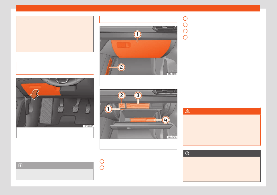
Operation
and cold could damage them or render
them useless.
●
Objects made from transparent materi-
al
s left inside the vehicle, such as glasses,
magnifying glasses or transparent suction
pads stuck to the windows can concentrate
sunlight and damage the vehicle.
storage compartment on the driv-
er's side
Fig. 139 On the driver side: storage compart-
ment.
Opening: Pull the handl
e
›
›
›
Fig. 139
.
Cl
osing
: Press the cover upwards until it clicks
into place.
Note
There might be a support for memory cards
on the inside of the cover.
Glove compartment
Fig. 140
On the front passenger side: glove
compartment cl
osed.
Fig. 141 On the front passenger side: glove
compartment open.
Key to the Fig. 140:
Gl
o
v
e compartment
St
or
age net
K
ey t
o the Fig. 141:
1
2
Air diffuser regulator
Support f
or memory car
ds
CD pl
ayer and car
d r
eader
›
›
›
page 206
On-board documentation
Opening and closing the glove compart-
ment
Opening: Pull the handle
›››
Fig. 140 and
open the glove compartment.
Closing: Press the glove compartment up-
wards.
Glove compartment cooling
With the AC on, cool air can be directed to-
wards the inside of the compartment. Turn
the air vent to open and close it.
WARNING
If the glove compartment is left open, the
risk of causing severe injuries in the event
of an accident, sudden braking or manoeu-
vring incr
eases.
●
Always keep the glove compartment
closed while the vehicle is in motion.
CAUTION
For structural reasons, some vehicle ver-
sions will have gaps behind the glove com-
partment (for inst
ance, behind the com-
partment for on-board documentation) into
which small objects may fall. This could
1
2
3
4
146
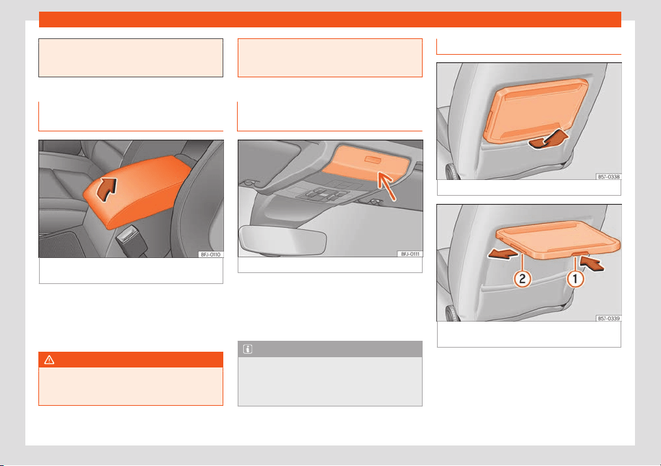
Transport and practical equipment
lead to strange noises and damage to the
vehicle. You should theref
ore not keep very
small objects in the glove compartment.
Storage compartment in the front
central armrest
Fig. 142 In the front central armrest: storage
compartment.
Opening: Giv
en the case
, pr
ess the unl
ock
butt
on and r
aise the centr
e armrest in the di-
rection of the arrow
›››
Fig. 142.
Closing: Lower the armrest.
WARNING
The centre armrest may obstruct the driv-
er's arm movements, which could cause an
accident and sever
e injuries.
●
Keep the storage compartments of the
centre armrest cl
osed at all times while the
vehicle is in motion.
Storage compartment in the roof
console (glasses case)
Fig. 143 On the roof console: glasses case.
Opening: Pr
ess and r
el
ease the butt
on
›
›
›
Fig. 143.
Closing: Press the cover upwards until it clicks
into place.
Note
For the surveillance of the cabin to work
correctly, the storage compartments must
be closed when locking the v
ehicle
›››
page 89.
Folding table
Fig. 144
Front left seat: folding table.
Fig. 145
Front left seat: folding table with
drinks hol
der
.
Depending on the model version, at the rear
of the fr
ont seats, ther
e may be “pl
ane-st
yl
e”
f
ol
ding tables for passengers in the rear
seats.
»
147
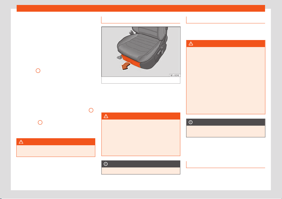
Operation
Opening the folding table
●
Pull the table up, in the direction of the ar-
r
o
w
, until it cat
ches
›
›
›
Fig. 144.
Folding the table or adjusting its inclina-
tion
The foldable table can be used at different
inclinations.
●
Press the unlocking lever under the table
›››
Fig. 145
1
and keep it that way.
●
Adjust: Adjust the inclination of the t
abl
e by
pr
essing the l
e
v
er
.
●
Fold: Push the table downwards while
pressing the lever.
Drink holder
A drink holder is built into the folding table
2
.
With the f
ol
dabl
e t
abl
e e
xt
ended, remove the
drink holder
2
following the direction of the
arr
o
w
. T
o st
or
e the drink hol
der, insert it into
the table against the direction of the arrow.
WARNING
The table must always be closed while
driving to decrease the risk of injuries.
Object holder under front seats*
Fig. 146
Drawer under the front seat
Opening: Pr
ess the t
ab on the dr
aw
er handl
e
and t
ak
e the drawer out.
Closing: Push the drawer under the seat until
it engages.
WARNING
If the drawer is left open, it could prevent
use of the pedals. This may cause serious
accidents and injuries.
●
Always keep the drawer cl
osed while the
vehicle is in motion. Otherwise, the drawer
and any objects in it could fall into the driv-
er's footwell and obstruct the pedals.
CAUTION
The drawer can contain 1.5 kg at most.
Other object holders
There are hangers on the struts of the doors
and the rear.
WARNING
Hanging clothes may decrease the driver's
visibility, which may cause serious acci-
dents and injuries.
●
Always hang clothes from hangers in
such a way that the driv
er's visibility is not
affected.
●
Only hang light pieces of clothing from
the hangers of the vehicle. Never leave
heavy, hard or sharp objects in the pockets
of these pieces of clothing.
●
Do not use clothes hangers to hang up
the clothing, as this could interfere with the
function of the head-protection airbags.
CAUTION
Each hanger is designed for a maximum
load of 2.5 kg.
Drink holder
Intr
oduction
The storage compartments of the driver and
passenger doors cont
ain a bottl
e hol
der
.
14
8
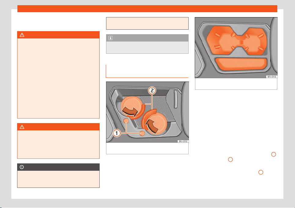
Transport and practical equipment
The folding tables of the front seats contain
mor
e bottl
e hol
ders
›
›
›
page 147
.
WARNING
Incorrect use of the bottle holders may
cause injuries.
●
Never put hot drinks in the drink holders.
In the event of sudden braking or an acci-
dent while driving, hot bever
ages in the
bottle holders might spill and cause burns.
●
Ensure that no bottles or other objects
are dropped in the driver footwell while
driving, as they could get under the pedals
and obstruct their working.
●
Never place glasses, food or other heavy
objects drink holders. These heavy objects
may be thrown across the cabin in the
event of an accident and cause serious in-
juries.
WARNING
Closed bottles may explode inside the ve-
hicle due to cold or heat.
●
Never leav
e closed bottles in the vehicle
if the temperature inside is very high or very
low.
CAUTION
Do not leave open cans in the drink holders
when the vehicle is in motion. If the drink is
spilled (e.g. due to sudden braking) it may
damage the vehicle and its electrical sys-
tem.
Note
The inside elements of the drink holders
can be e
xtracted for cleaning.
Drinks holder in the front part of the
centr
e consol
e
Fig. 147 In the front part of the centre console:
drinks hol
der (v
ariant 1).
Fig. 148
In the front part of the centre console:
drinks hol
der (v
ariant 2).
Depending on the features, there are two
drink hol
ders in the fr
ont part of the consol
e
›
›
›
Fig. 147
or
›››
Fig. 148.
Open and close the drink holder (variant 1)
Opening: Move the lid backwards.
Closing: Move the lid forwards.
Adjust the drink holder (variant 1)
To adapt the drink holder to the size of the
container, press the corresponding button
1
.
The f
ast
ening ring
2
opens.
When you ar
e not using the drink hol
der any
mor
e
, pr
ess the corr
esponding ring
2
in the
opposit
e dir
ection t
o the arr
o
w until it l
ocks.
149
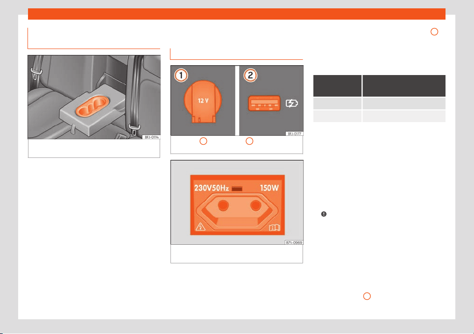
Operation
Drinks holder in the rear central
armr
est
Fig. 149
In the rear central armrest: drinks
hol
der
.
Use: L
ower the centre armrest.
When the drink hol
der is no l
onger in use
, lift
the armr
est again.
P
o
wer sockets
Vehicle power sockets
Fig. 150
1
12 volt socket.
2
USB socket on
the r
ear part of the centr
e consol
e
.
Fig. 151 On the left side of the luggage com-
partment: 230 v
olt po
w
er sock
et.
You can find 12 volt sockets on the front cen-
tr
e consol
e
, in the r
ear part of the centr
e con-
sol
e (betw
een the front seats) and in the lug-
gage compartment.
●
Lift the power socket cover
›››
Fig. 150
1
.
●
Insert the plug of the electrical appliance
int
o the po
w
er sock
et.
Maximum po
w
er consumption
Power socket
Maximum power con-
sumption
12 Volts 120 Watts
230 Volts 150 watts (300 watt peaks)
Electrical equipment can be connected to
the 12 v
olt po
w
er sock
et.
Mak
e sur
e that the maximum po
wer con-
sumption displayed on each outlet is not ex-
ceeded. The power consumption of devices is
shown on the model plate.
When connecting two or more electrical de-
vices at the same time, make sure that their
total consumption never exceeds 190 watts
›››
.
USB po
w
er sock
ets
Depending on the equipment and the coun-
try, the v
ehicl
e may al
so hav
e USB connec-
tions exclusively for charging or as a power
socket.
These USB ports are located in the rear part
of the centre console, between the front
seats
›››
Fig. 150
2
. These connectors can
150
Transport and practical equipment
work at a maximum power of up to 10.5 W per
port.
They ar
e
not
int
ended f
or fil
e pl
ayback.
230 volt power socket*
With the engine running, the power socket
›››
Fig. 151 activates automatically as soon as
a connector is plugged in. If there is enough
power available, the socket can still be used
while the engine is off
›››
Connect an electrical device: Open the co
v-
er and insert the plug int
o the po
w
er sock
et
as f
ar as possibl
e to unlock the built-in child
lock. The socket only supplies power once
the child lock is unlocked.
LED on the power socket
Steady green
light:
The childproof lock is unlocked.
The socket is ready to operate.
Fl
ashing green
light:
The ignition is switched off, but
there is enough power available
t
o continue supplying the socket
with current for a maximum of 10
minutes. If the connector is un-
plugged before this time elap-
ses, the socket is disconnected
and cannot be used again until
the ignition is switched on again.
Flashing red
light:
There is an anomaly, e.g. dis-
connection due to a current
surge or overheating.
Disconnection due to overheating
When the t
emper
at
ur
e e
x
ceeds a cert
ain val-
ue, the 230 volt socket inverter is automati-
cally disconnected. The disconnection pre-
vents overheating when the power consump-
tion of the connected devices is excessive or
the ambient temperature is very high. The
230-volt power supply can be used once
again after a cooling time. First unplug the
connector of the connected device and then
plug it back in again. This prevents the elec-
trical device from being switched on again if
this is not wanted.
WARNING
The electrical system is under high voltage!
●
Do not spill liquids onto the socket.
●
Do not plug adapters or extension cords
into the 230 volt power socket. Otherwise,
the int
egrated child lock will be unlocked
and the power socket will operate.
●
Do not insert conductive objects (a knit-
ting needle, for example) into the 230 volt
power socket.
WARNING
The power socket works only when the igni-
tion is on. Improper use may cause serious
injury or even fire. Childr
en should there-
fore not be left in the vehicle unattended if
the button is also left behind. Otherwise
there is a possibility that they may be in-
jured.
CAUTION
Always use the correct type of plugs to
av
oid damaging the sockets.
CAUTION
●
230 volt power socket:
–
Do not leave de
vices or connectors
that are too heavy (e.g. a transformer)
hanging directly from the power sock-
et.
–
Do not connect neon lamps.
–
Only connect devices to the socket if
the device and socket voltage match.
–
The built-in overload disconnect func-
tion prevents any electrical devices
that require a high start-up current
from turning on. In this case, unplug the
electrical device's power supply and
re-try the connection after about 10
seconds.
Note
●
The use of electrical appliances with the
engine switched off will cause a battery
discharge.
●
Shoul
d the connected appliance over-
heat, immediately switch it off and discon-
nect it from the socket.
»
151
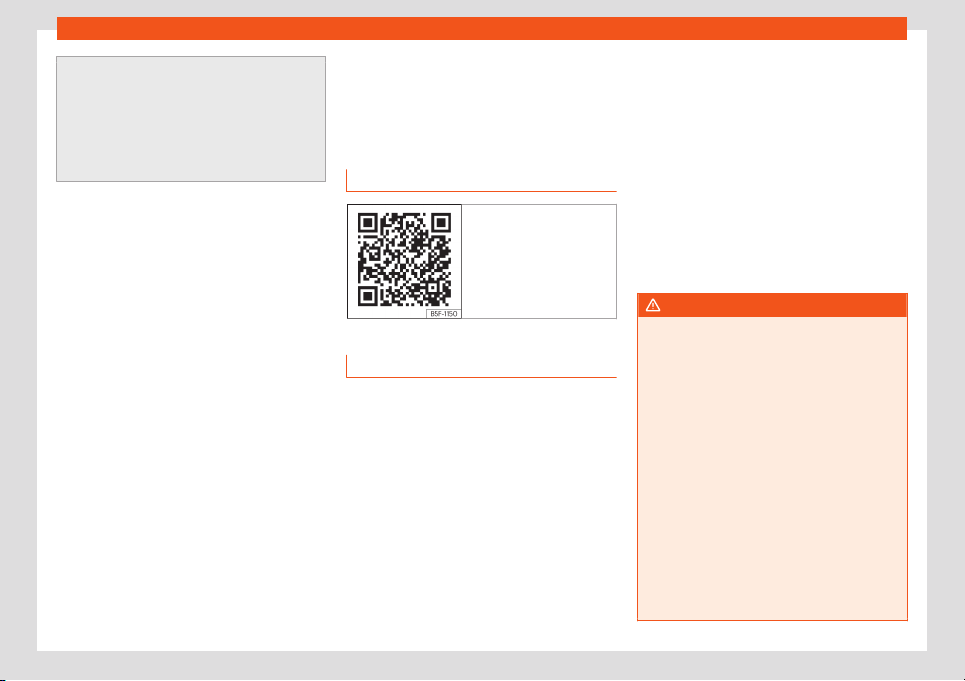
Operation
●
Before switching the ignition on or off, un-
plug the appliances from the USB por
ts to
protect them from any damage caused by
fluctuations in voltage.
●
Some appliances may not work properly
when connected to the 230 volt sockets
due to a lack of power (watts).
Air conditioning
Heating, v
entil
ation and
cooling
R
el
at
ed video
Fig. 152 Air conditioning
Introduction
Depending on the vehicle’s equipment, sever-
al syst
ems may hav
e been fitt
ed:
●
The
manual air conditioning
and the
Cli-
matr
onic cool and dehumidify the air. They
operate most effectively with the windows
and the sunroof closed.
To switch a specific function on, press the ap-
propriate button. Press the button again to
switch off the function.
The LED on each control lights up to indicate
that the respective function of a control has
been switched on.
Dust and pollen filter
The dust and pollen filter with its activated
charcoal cartridge serves as a barrier
against impurities in the air taken into the ve-
hicle interior.
The dust and pollen filter must be changed
regularly so that air conditioner performance
is not adversely affected.
If the filter loses efficiency prematurely due to
use in areas with very high levels of air pollu-
tion, the filter must be changed more fre-
quently than stated in the Service Schedule.
WARNING
Reduced visibility through the windows in-
creases the risk of serious accidents.
●
Always ensure that all windows are fr
ee
of ice and snow, and that they are not fog-
ged, so as to maintain good visibility of ev-
erything outside.
●
Only drive when you have good visibility.
●
Always ensure that you use the air condi-
tioning, heater or rear window heating to
maintain good visibility to the outside.
●
Never leave the air recirculation on for a
long period of time. If the cooling system is
switched off and air recirculation mode
switched on, the windows can mist over
very quickly, considerably limiting visibility.
●
Switch air recirculation mode off when it
is not required.
152
Air conditioning
WARNING
Stuffy or used air will increase fatigue and
reduce driver concentration possibly re-
sulting in a serious accident.
●
Never l
eave the fresh air fan turned off or
use the air recirculation for long periods of
time; the air in the vehicle interior will not
be refreshed.
CAUTION
●
To replace the pollen filter, al
ways visit a
service centre.
●
Switch the climate control or air condi-
tioner off if you think it may be broken. This
will avoid additional damage. Have the cli-
mate control or air conditioning checked
by a specialised workshop.
●
Repairs to the climate control or air con-
ditioning require specialist knowledge and
special tools. SEAT recommends visiting a
SEAT Official Service.
Note
●
When the cooling syst
em is turned off, air
coming from the outside will not be dried.
To pre
vent fogging of the windows, SEAT
recommends leaving the cooling system
(compressor) turned on. To do this, press
the
button. The button lamp should
light up.
●
The maximum heat output required to de-
frost windows as quickly as possibl
e is only
available when the engine has reached its
normal running temperature.
●
Keep the air intake slots in front of the
windscreen free of snow, ice and leaves to
ensure heating and cooling are not im-
paired, and to prevent the windows from
misting over.
●
The air from the vents flows through the
vehicle interior and is extracted by slots in
the luggage compartment designed for this
purpose. Therefore, you should av
oid ob-
structing these slots with any kind of ob-
ject.
●
Do not smoke while air recirculation
mode is on, as smoke drawn into the air
conditioning system leaves residue on the
evaporator, producing a permanent un-
pleasant odour.
●
It is advisable to turn on the air condition-
ing at least once a month, to lubricate the
system gaskets and prevent leaks. If a de-
crease in the cooling capacity is detected,
a Technical Service should be consulted to
check the system.
●
When the engine is under extreme strain,
switch off the compressor for a moment.
153
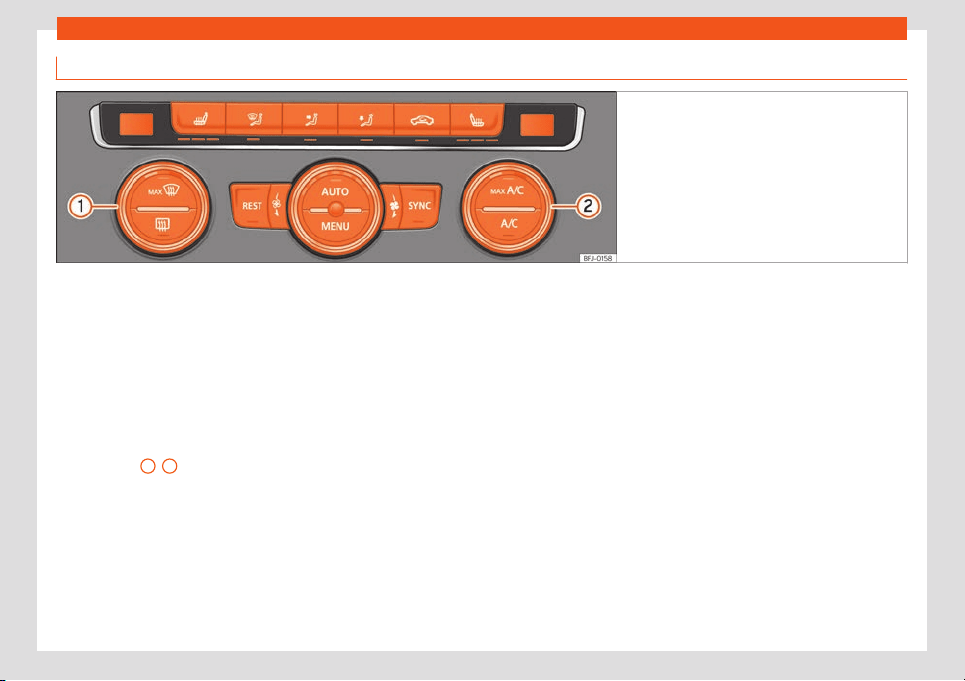
Operation
Climatronic* controls
Fig. 153 In the centre console: Climatronic con-
trols.
Automatic mode
Aut
omatic adjustment of t
emper
at
ur
e
, fan,
and air distribution. Automatic mode is disa-
bled when the ventilation is modified manual-
ly.
Cooling mode
Press the button to switch on or off the cool-
ing system.
Temperature
1
/
2
The temperature of the right and left sides
can be adjust
ed separ
at
ely using the adjust
-
ers. The sel
ect
ed t
emperature is shown on
the display of the climate control panel.
Synchronisation: press button so that
settings on the driver's side apply to the pas-
senger side. Use the temperature regulator
for the passenger side to set a different tem-
perature.
Blower
The power of the fan is automatically adjus-
ted.
The fan is also adjusted manually by turning
the control.
Air distribution / /
The airflow adjusts automatically for comfort.
It can also be manually distributed to the de-
sired zone by pressing the corresponding
button:
The airflow is directed towards the chest
The airflow is directed towards the foot-
well.
The airflow is directed at the windscreen.
Maximum cooling power
The recirculation of air and the cooling sys-
tem turn on automatically and air distribution
adjusts automatically to the position .
Defrost/demist function
The air drawn in from outside the vehicle is di-
rected at the windscreen and air recirculation
is automatically switched off. To defrost the
windscreen more quickly, the air is dehumidi-
fied at temperatures over approximately
+3°C (+38°F) and the fan runs at maximum
output.
Residual heat
When the engine is still warm but the ignition
switched off, the residual heat of the engine
can be used to keep the vehicle interior
154
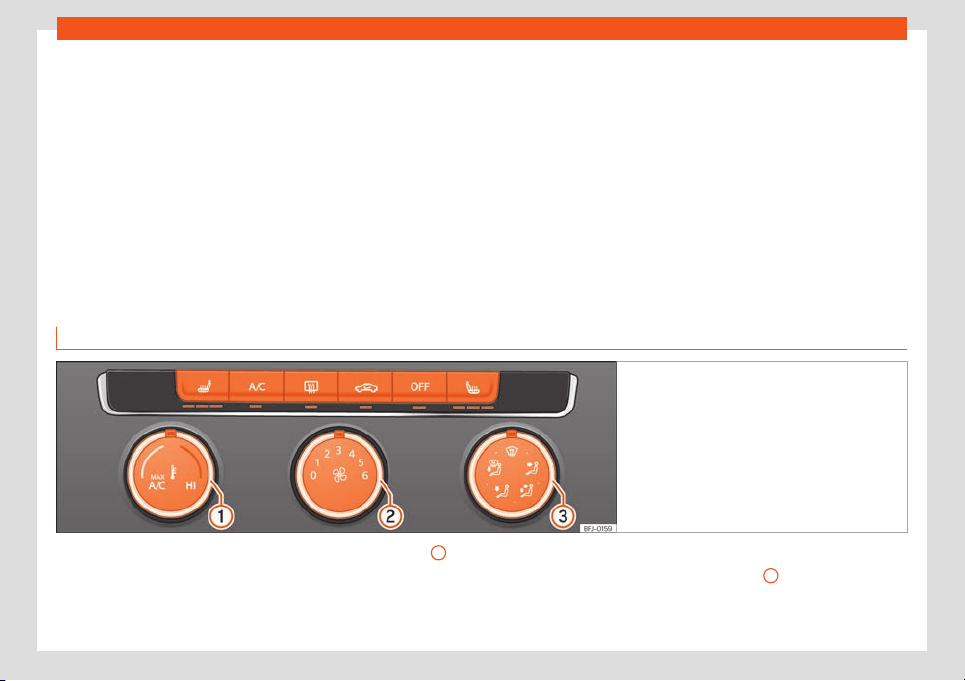
Air conditioning
warm. The function is disabled after 30 mi-
nut
es or when the char
ge of the 12-v
olt bat
-
t
ery is l
o
w.
Infotainment system:
The climate control operation and settings
menu will be displayed on the Easy Connect
system screen.
Heated rear window
This only works when the engine is running
and switches off automatically after a maxi-
mum of 10 minutes.
It should be switched off as soon as the glass
is demisted. By saving electrical power you
can also save fuel.
To avoid possible damage to the battery, an
automatic temporary disconnection of this
function is possible, coming back on when
normal operating conditions are re-establish-
ed.
Air recirculation
›››
page 158
Seat heating
›››
page 159
Switching off
Turn the fan adjuster completely to the left.
OR: Press the OFF function button on the info-
tainment system
›››
page 156.
Manual air conditioning controls
Fig. 154 In the centre console: manual air condi-
tioning controls.
Cooling mode
Pr
ess the butt
on t
o s
wit
ch on or off the cool
-
ing system.
Temperature
1
Turn the control to adjust the temperature.
Blower
T
urning the r
egul
at
or
2
sets the fan power.
At l
e
v
el 0 the f
an and manual air conditioning
ar
e disconnect
ed. L
evel 6 is the maximum.
»
155
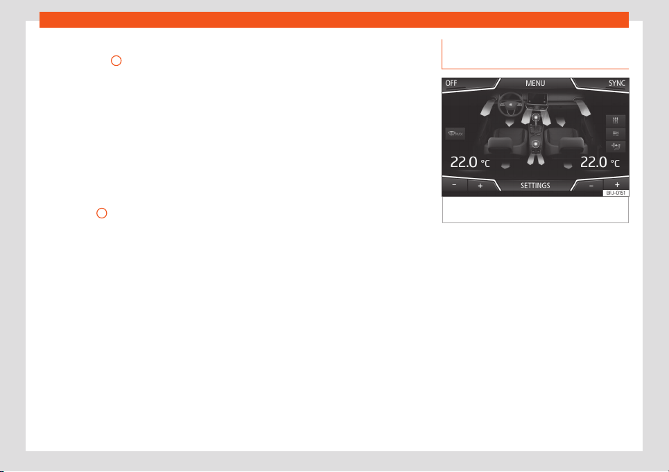
Operation
Air distribution / / / /
T
urning r
egul
at
or
3
distributes the air to the
desir
ed z
one:
The airfl
o
w is dir
ect
ed t
owards the chest
The airflow is directed towards the chest
and the footwell area.
The airflow is directed towards the foot-
well.
The airflow is directed towards the wind-
screen and the footwell area.
Defrost/demist function
When control
3
is in position the air fl
o
w is
dir
ect
ed at the windscr
een and air r
ecir
cula-
tion is disconnected automatically or not ac-
tivated. Increase the fan power to clear the
windscreen of condensation as soon as pos-
sible. To dehumidify the air, the cooling sys-
tem will automatically switch on.
Maximum cooling power
When the control is in position air recir-
culation and the cooling system are connec-
ted automatically and the air flow is automat-
ically adjusted to position .
Heated rear window
This only works when the engine is running
and switches off automatically after a maxi-
mum of 10 minutes.
It should be switched off as soon as the glass
is demisted. By saving electrical power you
can also save fuel.
To avoid possible damage to the battery, an
automatic temporary disconnection of this
function is possible, coming back on when
normal operating conditions are re-establish-
ed.
Air recirculation
›››
page 158
Seat heating
›››
page 159
Switching off
Press button or manually set the fan to .
Operating the Climatronic through
the Easy Connect system*
Fig. 155
Easy Connect screen: Climate control
menu.
In the Easy Connect system it is also possible
t
o perf
orm v
arious adjustments t
o the Clima-
tr
onic.
Open the
air conditioner menu
●
Pr
ess the button of the Climatronic
control panel.
On the screen you can view and change the
current settings, such as, for example, the
temperature set for the driver and passenger
sides. Temperatures up to +22°C (+72°F) are
shown with blue arrows, and temperatures
over +22°C (+72°F) with red arrows.
To switch a function on or off, or to select a
submenu, you must press the corresponding
function button.
156
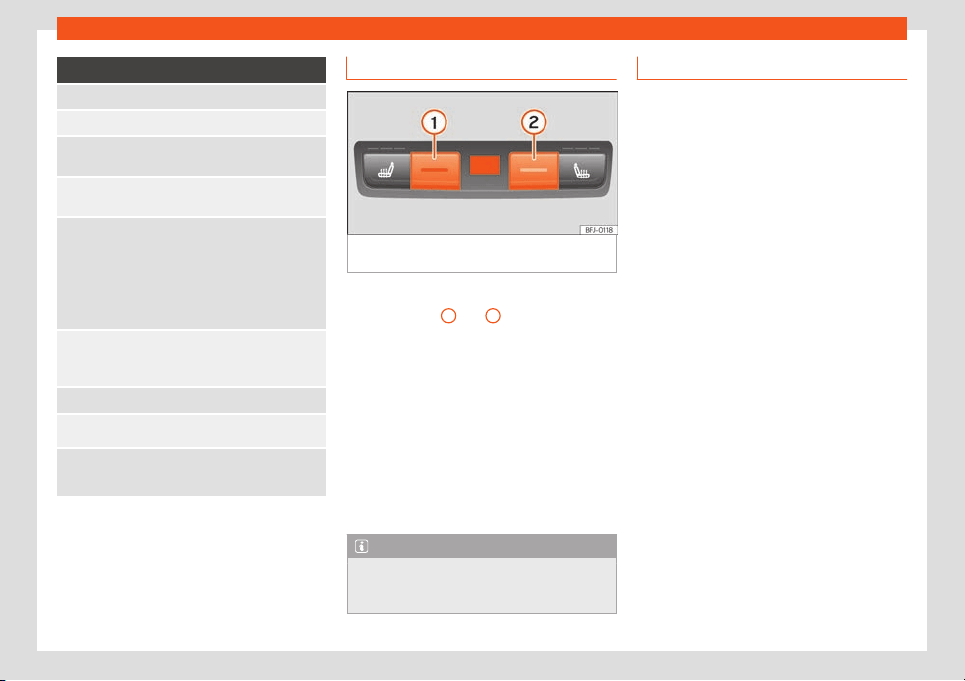
Air conditioning
Function button: Function
OFF: Climatronic is switched off.
ON: Climatronic is swit
ched on.
SYNC: Synchronise driver and front passenger tem-
peratur
es.
SETTINGS The air conditioning settings submenu is
opened. The following settings can also be adjusted:
Automatic supplementary heater: to
activ
ate/deactivate the automatic activ
ation of
the auxiliary heating for colder countries (only
for engines with auxiliary heating). With the op-
tion deactivated, depending on the outside tem-
perature the heating may need more time than
normal to reach a comfortable temperature.
Automatic air recirculation: to switch
automatic air recircul
ation on and off
›››
page 158.
Back : Cl
ose the submenu.
*: The auxiliary heater submenu opens.
: It enables activation and deactivation of the
PureAir and opens the submenu.
Rear controls
Fig. 156 In the rear part of the centre console:
controls for the rear seats.
Temperature
●
Press buttons
1
and
2
›
›
›
Fig. 156
t
o ad-
just the t
emper
ature.
Setting the temperature on the infotain-
ment system
●
Press the button in the control panel.
●
Press the function button to set the temper-
ature of the rear seats.
●
Press the function buttons to set the tem-
perature.
The display shows the temperature selected.
Note
When function button is active on the In-
fotainment System, the rear control
s do not
work.
Climate control usage instructions
The interior cooling system only works when
the engine is running and fan is switched on.
Economic use of the air conditioning
When the air conditioning is switched on, the
compressor consumes engine po
wer and has
influence on fuel consumption.
The air conditioner operates most effectively
with the windows and the panoramic sliding
sunroof closed. However, if the vehicle has
heated up after standing in the sun for some
time, the air inside can be cooled more quick-
ly by opening the windows and the panoram-
ic sliding sunroof briefly.
Change the temperature unit (Climatron-
ic)
The temperature display can be changed
from Celsius to Fahrenheit on the screen of
the Infotainment system using the Infotain-
ment button > Settings > Units.
The cooling system cannot be activated
If the air conditioning system cannot be
switched on, this may be caused by the fol-
lowing:
●
The engine is not running.
●
The fan is switched off.
●
The air conditioner fuse has blown.
»
157
Operation
●
The outside t
emper
at
ur
e is l
o
w
er than ap-
proximately +3°C (+38°F).
●
The air conditioner compressor has been
temporarily switched off because the engine
coolant temperature is too high.
●
Another fault in the vehicle. Have the air
conditioner checked by a specialised work-
shop.
Special characteristics
If the humidity and temperature outside the
vehicle are high, condensation can drip off
the evaporator in the cooling system and
form a pool underneath the vehicle. This is
normal and does not indicate a leak!
Note
After starting the engine, any residual hu-
midity in the air conditioner could mist over
the windscreen. Swit
ch on the defrost func-
tion as soon as possible to clear the wind-
screen of condensation.
Air vents
To ensure proper heating, cooling and venti-
l
ation in the v
ehicl
e int
erior
, the air v
ents must
r
emain open.
●
Turn the corresponding thumbwheel in the
required direction to open and close the air
vents. When the thumbwheel is in the posi-
tion, the corresponding air vent is closed.
●
Change the air direction using the ventila-
tion grille lever.
There are other additional, non-adjustable air
vents in the dash panel, in the footwells and in
the rear area of the passenger compartment.
Note
Food, medicine and other heat or cold sen-
sitive objects should never be placed in
fr
ont of the air outlets as they may be dam-
aged or made unsuitable for use by the air.
Air recirculation
Air recirculation mode prevents the ambient
air fr
om ent
ering the int
erior
.
When the outside t
emper
at
ure is very high,
selecting manual air recirculation mode for a
short period refreshes the vehicle interior
more quickly.
For safety reasons, air recirculation mode is
switched off when the button is pressed
or the air distributor turned to .
Switching the manual air recirculation
mode on and off
●
Press the button to connect or discon-
nect manual air recirculation.
Climatronic automatic air recirculation
mode
With the automatic air recirculation mode ac-
tivated, the entry of fresh air into the cabin in-
terior is enabled. If the system detects a high
concentration of hazardous substances in the
ambient air, air recirculation mode is switched
on automatically. When the level of impurities
drops to within a normal range, recirculation
mode is switched off.
The system is unable to detect unpleasant
smells.
●
Automatic air recirculation is activated and
deactivated in the climate control menu
›››
page 156.
The air recirculation will not connect auto-
matically in versions without humidity sensor
and in the following external conditions:
●
The outside temperature is lower than +3°C
(+38°F).
●
The cooling system is switched off and the
outside temperature is below +10°C (+50°F).
●
The cooling system is switched off, the out-
side temperature is below +15°C (+59°F) and
the windscreen wipers are switched on.
WARNING
Observe the safety warnings
›››
in Intro-
duction on page 153.
158
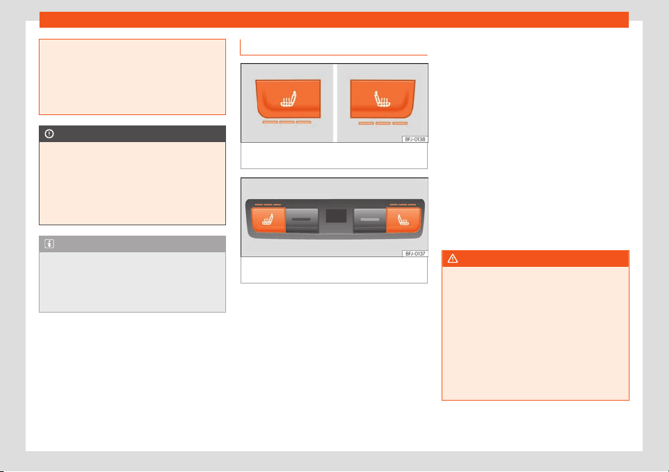
Air conditioning
●
If the cooling system is switched off and
air recirculation mode s
witched on, the
windows can mist over very quickly, con-
siderably limiting visibility.
●
Switch air recirculation mode off when it
is not required.
CAUTION
Do not smoke when air recirculation is
s
witched on in vehicles with an air condi-
tioner. The smoke t
aken in could lie on the
cooling system vaporiser and on the acti-
vated charcoal cartridge of the dust and
pollen filter, leading to a permanently un-
pleasant smell.
Note
Climatronic: air recirculation mode is acti-
vated to prevent e
xhaust gas or unpleasant
odours from entering the vehicle interior
when it is in reverse and while the automat-
ic windscreen wiper is working.
Seat heating*
Fig. 157 In the centre console: front seat heat-
ing switches.
Fig. 158 In the rear part of the centre console:
r
ear seats heating s
wit
ch.
With the engine on, the seat cushion and the
seat backr
est can be heat
ed el
ectrically.
Contr
ol seat heating
●
Pr
ess butt
ons
or on the control panel
to turn on the seat heating as high as possi-
ble.
●
Press buttons or repeatedly to adjust it
to the required level.
●
To turn off the seat heating, press button
or repeatedly until no LEDs are lit.
If the ignition is switched on again in approx.
the next 10 minutes, the driver seat heating is
automatically turned on to the level set the
last time.
Cases in which the heat seating should
not be switched on
Do not switch the seat heating on if any of the
following conditions are met:
●
The seat is not occupied.
●
The seat has a cover.
●
A child seat has been installed on the seat.
●
The seat cushion is wet or damp.
●
The outdoor or indoor temperature is great-
er than +25°C (77°F).
WARNING
People who cannot perceive pain or tem-
perature because of medications, paralysis
or chronic diseases (e.g. diabet
es) or have
a limited perception of these, may suffer
burns to the back, buttocks or legs when
using seat heating.
●
People with limited pain and temperature
thresholds must never use seat heating.
●
If an abnormality in the device's temper-
ature control is detected, have it checked
by a specialist workshop.
»
159
Operation
WARNING
If the fabric of the cushion is wet, this can
adversely affect the operation of the seat
heating, increasing the risk of burns.
●
Make sure the seat cushion is dry prior t
o
using the seat heater.
●
Do not sit on the seat with clothing that is
wet or damp.
●
Do not leave clothing that is wet or damp
on the seat.
●
Do not spill liquid on the seat.
CAUTION
●
To avoid damaging the heating elements
of the seat heaters, please do not kneel on
the seat or apply sharp pressur
e to a single
point on the seat cushion or backrest.
●
Liquids, sharps objects and insulating
materials (e.g. covers or child seats) can
damage the seat heating.
●
In the event of smells, switch off the seat
heating immediately and have it inspected
by a specialised workshop.
For the sake of the environment
The seat heating should remain on only
when needed. Otherwise, it is an unneces-
sary fuel waste.
160
Air conditioning
Auxiliary heating (additional
heating)*
Intr
oduction
The auxiliary heater runs on fuel from the ve-
hicle's tank and can be used while you are
driving and when the vehicle is st
ationary.
The auxiliary heater can be switched on using
the fast heating button of the air conditioning
controls, with the remote control or by previ-
ously programming a departure time in the
auxiliary heater menu of the infotainment sys-
tem.
In winter, with the auxiliary heater switched
on, you can defog the windscreen and leave
it free of ice and snow (if it is a thin layer) be-
fore you start driving.
If the outside temperature is very high, the ve-
hicle interior can be ventilated with the en-
gine off using the auxiliary heater.
WARNING
The auxiliary heater exhaust fumes contain
carbon monoxide, an odourless and colour-
less t
oxic gas. Carbon monoxide can cause
people to lose consciousness. It can also
cause death.
●
Never switch on the auxiliary heater or
leave it running in enclosed spaces or
areas with no ventilation.
●
Never programme the auxiliary heater so
that it swit
ches itself on and is running in an
enclosed space or an area with no ventila-
tion.
WARNING
The components of the auxiliary heater are
e
xtremely hot and could cause a fire.
●
Alw
ays park your vehicle so that no part
of the exhaust system can come in contact
with easily flammable materials that might
be below the vehicle, such as dried grass.
CAUTION
Never place food, medicines or other tem-
perature-sensitive objects close t
o the air
vents. Food, medicines and other objects
sensitive to heat or cold may be damaged
or made unsuitable for use by the air com-
ing from the vents.
Switching the auxiliary heater on
and off
Connection
The independent heating can be connect
ed
in the f
oll
o
wing w
ays:
●
Pr
ess the f
ast heating button on the air con-
ditioning control panel
›››
page 154. The
control lamp of the button will light up.
●
Press button on the radio-operated re-
mote control
›››
page 162.
●
Automatically scheduling a departure
time*
›››
page 163.
Disconnection
The independent heating can be switched off
in the following ways:
●
Press the fast heating button on the air con-
ditioner's control panel . The control lamp
on the button turns off.
●
Press button on the radio-operated re-
mote control
›››
page 162.
●
Automatically at the scheduled departure
time or after the programmed operating time
has elapsed
›››
page 163.
●
Automatically when the control lamp
(fuel level indicator) lights up
›››
page 342.
●
Automatically when the 12-volt battery
charge drops too low
›››
page 358.
Things to note
Once switched off, the auxiliary heater will
continue to operate for a short period of time
in order to burn the fuel remaining in the sys-
tem and also to expel the exhaust fumes.
161
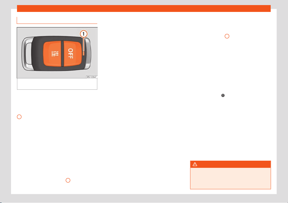
Operation
Radio-operated remote control
Fig. 159
Auxiliary heating: radio-operated re-
mot
e contr
ol
.
Fig. 159
S
wit
ch the auxiliary heat
er on
S
wit
ch the auxiliary heat
er off
Contr
ol lamp
If the buttons of the remote control are press-
ed unnecessarily, it could switch on the auxili-
ary heater involuntarily, even when it is out of
range or when the control lamp is flashing.
To switch on and off the independent heating,
the button must be pressed and held for ap-
proximately 1 second.
Control lamp on the remote control
When the buttons are pressed, the control
lamp on the remote control
1
provides the
user with diff
er
ent inf
ormation:
1
It lights up for approx. 2 seconds
●
In green: The auxiliary heat
er has been
s
wit
ched on with butt
on
.
●
In r
ed:
The auxiliary heat
er has been
switched off con with button .
Flashes slowly for approx. 2 seconds
●
In green: No on signal has been received.
The remote control is out of range. Move
closer to the vehicle.
●
In red: No off signal has been received. The
remote control is out of range. Move closer to
the vehicle.
Flashes quickly approx. 2 seconds
●
In green: The independent heating is
blocked. Possible causes: the fuel tank is al-
most empty, the 12-volt battery charge is
very low or there is a fault.
It lights up for approx. 2 seconds
●
In orange (then in green or in red): The re-
mote control battery is almost flat. However,
the on or off signal has been received.
●
In orange (then flashes green or red): The
remote control battery is almost flat. No on or
off signal has been received.
Flashes for around 5 seconds
●
In orange: The remote control battery is flat.
No on or off signal has been received.
Changing the battery of the radio-operat-
ed remote control
When pressing the buttons, if the control
lamp of the remote
1
flashes for approx. 5
or
ange or does not light up
, the batt
eries
must be r
epl
aced.
The batt
ery is l
ocated beneath a cover on
the back of the remote control.
●
To open the cover, lift it slightly at the bot-
tom and slide it down.
●
Remove the old battery.
●
Insert the new battery. When doing so, take
into account the polarity and use batteries of
the same type
›››
.
●
Replace the battery cover by inserting the
t
abs at the t
op and pr
essing the bott
om.
R
ange
The r
eceiv
er is inside the vehicle. The remote
control, when fitted with new batteries, has a
range of several hundred metres. Obstacles
between the remote control and the vehicle,
bad weather conditions and discharged bat-
teries can considerably reduce the range of
the remote control.
WARNING
Swallowing a battery with a 20 mm diame-
ter or any other button battery can cause
serious and even fat
al injuries within a very
short time.
162
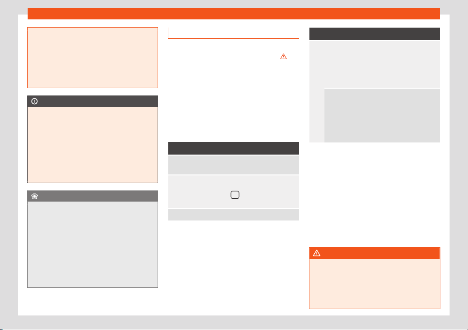
Air conditioning
●
Always keep the remote control, k
eyrings
with batteries, the spare batteries, button
batteries and all other batteries over 20
mm out of reach of children.
●
If you suspect that someone may have
swallowed a battery, seek immediate med-
ical attention.
CAUTION
●
The r
adio frequency remote control con-
tains el
ectronic components. Therefore,
avoid getting it wet and exposing it to
knocks or direct sunlight.
●
The use of inappropriate batteries may
damage the radio frequency remote con-
trol. For this reason, always replace the
used battery with another of the same volt-
age, size and specifications.
For the sake of the environment
●
Please dispose of your used batteries
correctly and with respect for the environ-
ment.
●
The r
emote control battery may contain
perchlorate. Observe the legal provisions
regarding disposal.
●
Care should be taken so as not to oper-
ate the remote control unintentionally so
as to prevent the auxiliary heater being
switched on accidentally.
Programming the auxiliary heater*
Before programming it, check that the vehi-
cle's date and time are set correctly
››
›
.
The auxiliary heater is programmed in the
Auxiliary heater menu of the infotainment
system.
Open the
Auxiliary heater menu.
●
Press the button of the Climatronic
control panel.
●
Press the function button.
Function button: function
Switch off: The auxiliary heater is immediately
switched off.
Heat, Ventilate: Set t
o heat or ventilate the vehi-
cle int
erior when the auxiliary heater is switched on.
Press the function button to select the desired
mode.
Set: Opens the Auxiliary heater menu.
Function button: function
Departure time 1, Departure time
2, Departure time 3: Three different de-
parture times (hh.mm) may be progr
ammed. If
the auxiliary heater should only be switched
on a certain day of the week, this can also be
selected.
Duration: The duration determines the oper-
ating time of the auxiliary heater when switch-
ed on using the f
ast heating button on the
air conditioning controls. The duration is also
used to calculate the departure time for the
manual air conditioner. It can be set between
10 and 60 minutes at 10-minute intervals.
The programmed departure time determines
the appr
o
ximat
e time it shoul
d t
ak
e t
o reach
the temperature set in the vehicle. The start of
the heating operation is determined automat-
ically depending on the outside temperature.
Checking the programming
When a departure time is activated and the
ignition is switched off the control lamp of the
fast heating button lights up for approxi-
mately 10 seconds.
WARNING
Never programme the auxiliary heater so
that it switches itself on and is running in an
enclosed space or an area with no ventila-
tion. The auxiliary heat
er exhaust fumes
contain carbon monoxide, an odourless
and colourless toxic gas. Carbon monoxide
»
163
Operation
can cause people to lose consciousness. It
can also cause death.
Usage instructions
The auxiliary heater exhaust system located
below the vehicle must be kept clear of sno
w,
mud and other objects. The exhaust fumes
must be able to exit freely. The emissions
generated by the auxiliary heater are re-
moved via an exhaust pipe fitted underneath
the vehicle.
On heating the vehicle interior, depending on
the outside temperature, the warm air is first
directed at the windscreen and then to the
rest of the vehicle interior through the air
vents. Directing the diffusers – towards the
windows for example – can affect air distribu-
tion.
When the auxiliary heater is not switched
on
●
The auxiliary heater requires about as
much power as the dipped beam headlights.
If the 12-volt battery charge is too l
ow, the
auxiliary heater switches off automatically
and cannot be switched on. This avoids prob-
lems when starting the engine.
●
The heating must be activated every time
you want to set off. Similarly, the departure
time must reactivate each time.
●
The control lamp (fuel level indicator)
lights up.
Note
●
Noises will be heard while the auxiliary
heater is running.
●
When the air humidity is high and the in-
side temperat
ure low, condensation from
the heating and ventilating system may
evaporate when the auxiliary heater is
switched on. In this case, steam may be re-
leased from underneath the vehicle. This
does not mean that there is a vehicle mal-
function.
●
If the vehicle is tilted, e.g. if parked on a
slope, the operation of the auxiliary heater
may be restricted if the fuel tank level is
low (just above the reserve level).
●
If the auxiliary heater is used a number of
times for a long period of time, the 12-volt
battery will lose its charge. To recharge the
battery, the vehicle must be driven for a
number of kilometres from time to time. As
a guideline: the journey should last approx-
imately as long as the heater was connec-
ted.
●
At temperatures below +5 °C (+41 °F), the
auxiliary heater may switch itself on auto-
matically when the engine is switched on.
The auxiliary heater is switched off again
after a certain time.
164

Introduction
Infotainment System
Intr
oduction
Saf
et
y w
arnings
Saf
et
y w
arnings regarding the Info-
tainment system
Only operate the infotainment system and its
various functions when the traffic situation
really permits this.
WARNING
●
Before starting the trip, you should f
amili-
arise yourself with the different infotain-
ment system functions.
●
High audio volume may represent a dan-
ger to you and to others. Hearing may be
impaired if the volume is too high, even for
short periods of time.
●
Changes to the Infotainment system set-
tings should be made when the car is stop-
ped, or by a passenger.
WARNING
Current traffic requires maximum attention
from public road users. Distracting the driv-
er in any way can lead to an accident and
cause injuries. Oper
ating the Infotainment
system can distract your attention from the
traffic.
●
Always drive carefully and responsibly.
●
Sel
ect volume settings that allow you to
hear sounds from outside the vehicle at all
times (e.g. emergency services sirens and
horns).
WARNING
The volume level may suddenly change
when you s
witch audio source or connect a
new audio source.
●
L
ower the base volume before connect-
ing or switching audio sources.
WARNING
The driving recommendations and traffic
indications shown on the navigation system
may differ from the current traffic sit
uation.
●
Traffic signs and traffic regulations have
priority over the recommendations and dis-
plays provided by the navigation system.
WARNING
Connecting, inserting or removing a data
medium while driving can distract your at-
tention from the traffic and cause an acci-
dent.
WARNING
Place the connecting cables of external
equipment so that they do not interfere
with the driver’s mobilit
y.
WARNING
External devices that are loose or not prop-
erly secured could move around the pas-
senger compartment during a sharp ma-
noeuvr
e or accident.
●
Avoid placing external devices on the
doors, windscreen, steering wheel, dash
panel, the backs of the seats, on top of or
near the area marked “AIRBAG” or between
these areas and the occupants. They could
cause serious injury in an accident, espe-
cially when the airbags inflate.
WARNING
The armrest* must always remain closed
during the journey as it could restrict the
driver’s mov
ements.
WARNING
Opening the CD or DVD player can lead to
injuries from invisible laser radiation.
●
Have CD or DVD r
epaired only by a spe-
cialist workshop.
»
165
Infotainment System
CAUTION
The Infotainment system can be damaged
by the incorrect insertion of a data storage
device or the inser
tion of an incompatible
data storage device.
●
When inserting a data storage device,
make sure it is correctly positioned.
●
Applying force may irreparably damage
the memory card slot locking mechanism.
●
Only use compatible memory cards.
●
When inserting and removing CDs and
DVDs, always hold them at right angles to
the front of the CD/DVD drive without tilt-
ing so as not to scratch them.
●
If a CD or DVD is inserted while another is
already in the unit or being ejected, the
CD/DVD drive may be damaged. Always
wait until the data medium is completely
ejected.
CAUTION
Foreign objects stuck to a CD or DVD, or if it
is not round, the player may be damaged.
●
Only clean, standard 12 cm CDs or DVDs
shoul
d be used.
–
Do not affix stickers or other items to
the data medium. Stickers may peel off
and damage the drive.
–
Do not use printable data media. Prin-
ted labels and coverings may peel off
and damage the CD/DVD drive.
–
Do not insert 8 cm single CDs or irregu-
larly shaped CDs or DVDs.
–
Do not insert D
VD-Plus discs, Dual
Discs or Flip Discs, as these are thicker
than normal CDs.
CAUTION
The vehicle loudspeakers may be dam-
aged if the v
olume is too high or the sound
is distorted.
Note
For the proper functioning of the Infotain-
ment system it is important that the date
and time set in the vehicle ar
e correct.
166
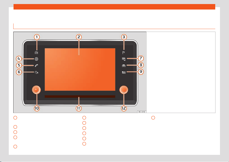
Introduction
Overview of the unit
Media Syst
em Plus / Navi Syst
em / Navi Syst
em Plus
Fig. 160 Overview of the controls
Radio Mode (change of band frequency
›
›
›
page 190
T
ouchscr
een
›
›
›
page 171
Navigation Mode
›››
page 215
Media mode (audio sources)
›››
page 198
Phone Mode
›››
page 233
1
2
3
4
5
Voice control
›
›
›
page 1
7
7
Full Link
›
›
›
page 180
Vehicle settings
›››
page 82,
›››
page 229
Main menu
›››
page 170
Volume. Off/on
›››
page 170
Proximity sensor
›››
page 173
6
7
8
9
10
11
Settings button (search and selection)
›
›
›
page 1
70
12
167
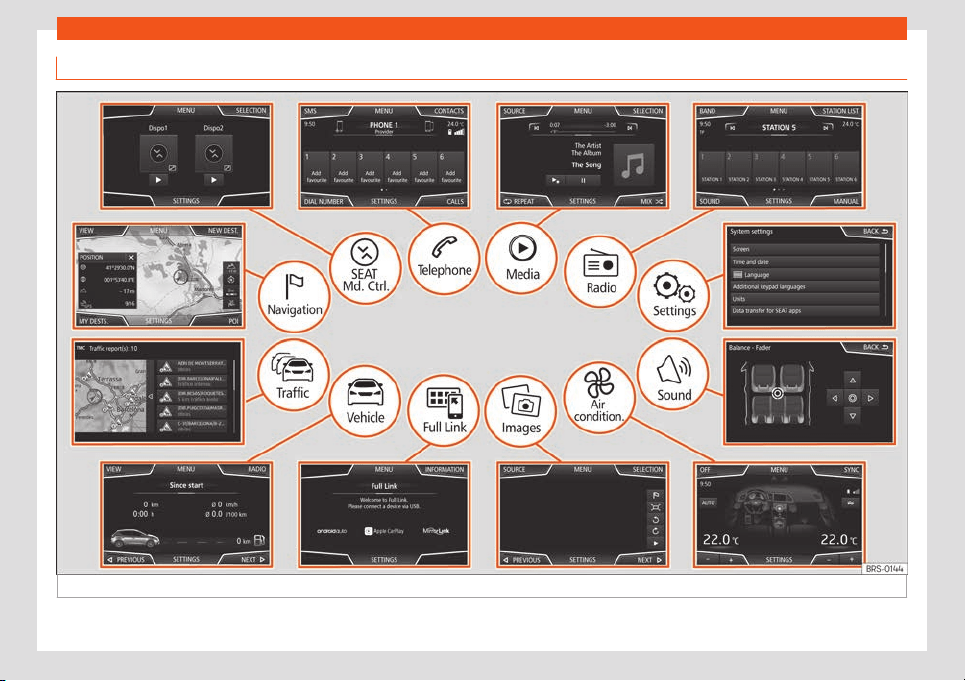
Infotainment System
Main menus
Fig. 161
Menu summary.
168

Introduction
Radio
›››
page 190
RADIO main menu
›››
page 190
RDS r
adio data services
››
›
page 191
Digital radio mode
›››
page 192
Memory buttons
›››
page 193
Save station logos
›››
page 194
Select, tune and save stations
›››
page 194
SCAN automatic playback
›››
page 195
TP traffic information
›››
page 195
Setup
›››
page 196
Media
›››
page 198
Data and file formats
›
››
page 198
Playback order
››
›
page 201
›››
page 201
Change the media source
›››
page 203
Change track
›››
page 204
Selecting an album by cover
›››
page 204
Selecting a track from a track list
›››
page 205
Data bank view
›››
page 206
Insert or remove a CD or DVD
›››
page 206
Memory card
›››
page 207
External data storage device connected to the USB
port
›››
page 207
External audio source connected to the AUX-IN multi-
media socket
›››
page 208
External audio source with Bluetooth
®
›››
page 208
Images
›››
page 213
Setup
›››
page 214
Navigation
›››
page 215
New destination
››
›
page 217
Rout
e options
›››
page 218
›››
page 219
My destinations
›››
page 219
Special destinations (POI)
›››
page 221
View
›››
page 221
Split screen
›››
page 221
Map display
›››
page 222
Traffic bulletins and dynamic guide
›››
page 223
Predictive navigation
›››
page 224
Import vCards
›››
page 224
Navigation with images
›››
page 224
Road signs
›››
page 224
Route guidance in Demo mode
›››
page 225
Setup
›››
page 225
Offroad mode
›››
page 227
Vehicle
Instrument panel
›
››
page 229
Sport
›››
page 230
Offr
oad
›››
page 230
Consumers
›››
page 231
Driving data
›››
page 231
Ecotrainer
›››
page 231
Vehicle status
›››
page 232
Traffic
›››
page 223
Traffic information (TP)
›
››
page 195
Traffic bulletins and dynamic guide
›
››
page 223
Telephone
›››
page 233
Bluetooth
®
›››
page 234
Tethering
›››
page 235
Function buttons
›››
page 236
Enter number
›››
page 238
Agenda
›››
page 239
Short messages (SMS)
›››
page 240
Call list
›››
page 241
Quick dial keys
›››
page 241
Setup
›››
page 242
Sound
›››
page 176
Full Link
›››
page 180
Requirements
››
›
page 181
Activation of Full Link
›››
page 182
Tethering of portable devices
›››
page 183
MirrorLink
®
›››
page 184
Apple CarPlay™
›››
page 184
Android Auto™
›››
page 185
Frequently Asked Questions
›››
page 186
SEAT Md. Climate
›››
page 186
WLAN access point
›››
page 187
Images
›››
page 213
Control
›››
page 156
Setup
›››
page 174
169
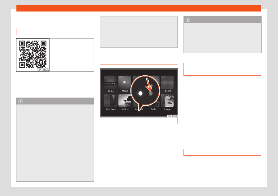
Infotainment System
General instructions for use
Intr
oduction
Fig. 162 Related video
If the setup is changed, this may change the
displ
ay on the scr
een and the Inf
ot
ainment
syst
em may behav
e in a manner diff
erent to
that described in this manual.
Note
●
Just press a button or the screen to use
the infotainment syst
em's functions.
●
The equipment’s software depends on
the market in question, so it is possible that
not all of the function buttons or described
functions are available. The equipment is
not faulty if a function button is missing.
●
Due to country-specific legislation, cer-
tain functions may not be available on the
screen when the vehicle is travelling above
a certain speed.
●
Using a mobile telephone inside the vehi-
cle may provoke noise in the speakers.
●
Restrictions on the use of devices using
Bluetooth
®
technology may apply in some
countries. For further information, contact
the local authorities.
●
On vehicles with ParkPilot, the audio vol
-
ume is automatically lowered when reverse
gear is selected. The volume can be low-
ered in the menu Sound > Volume.
Diagram of the menus
Fig. 163
Main menu
The Infotainment system touchscreen can be
used t
o sel
ect the diff
er
ent main menus.
Pr
ess the Inf
ot
ainment button to open the
menus summary .
The display of the touchscreen's main menu
can be switched between “grid” and “carou-
sel” and vice-versa using the menu Settings
> Screen
›››
page 174.
Note
Depending on the infotainment version,
there may be more icons on the second
page. In this case, to see the remaining
icons pr
ess the function button
›››
Fig. 163
(arrow) or slide your finger horizontally
across the screen.
Rotary push buttons and infotain-
ment buttons
Rotary/push buttons
The l
eft r
ot
ary push butt
on
is the on/off
butt
on if pressed and the volume knob if
turned.
The right rotary pushbutton is the search but-
ton if turned and the selection button if press-
ed.
Infotainment buttons
The Infotainment buttons are used by press-
ing them or pressing and holding.
Switching on and off
When the system is turned on, it starts up with
the v
olume at which it w
as t
urned off
, as l
ong
as it does not e
x
ceed the preset maximum
start-up volume. Select Sound > Volume.
170
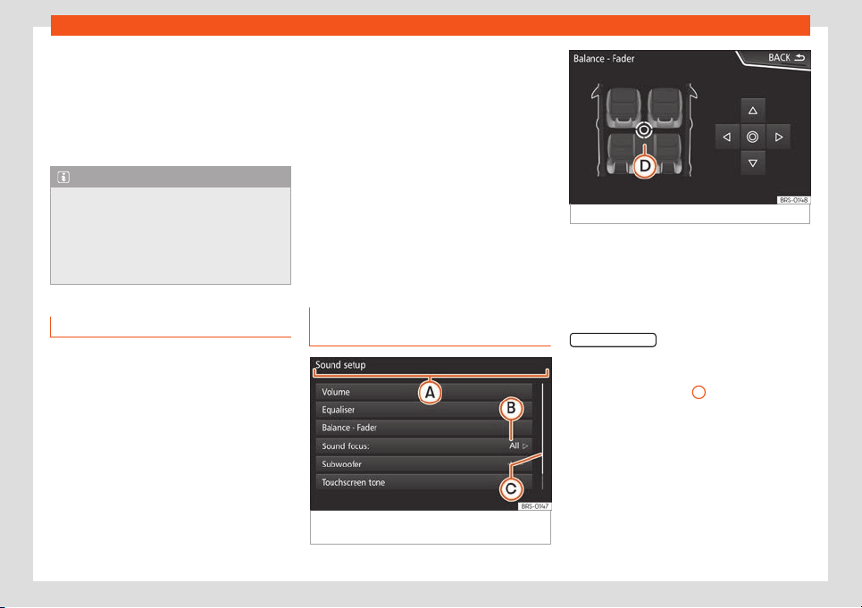
Introduction
The unit will switch off automatically when
the k
ey is r
emo
v
ed fr
om the ignition or when
the on/off butt
on is pr
essed (depending on
the equipment fitted or the vehicle). If the In-
fotainment system is switched on again, it will
switch off automatically after approximately
30 minutes (switch-off delay).
Note
●
The Infotainment system is a part of the
vehicle
. It cannot be used in any other vehi-
cle.
●
If the battery has been disconnected, the
ignition must be activated before switching
on the Infotainment system.
Changing the basic volume
Increasing or decreasing the volume or
muting the sound
R
aise the v
olume
: t
urn the v
olume contr
ol
clockwise or move the left thumbwheel on
the multifunction steering wheel upward .
Lower the volume: turn the volume control
clockwise or move the left thumbwheel on
the multifunction steering wheel downward
.
Changes in volume are indicated by a vol-
ume bar on the screen. The volume can be
controlled using the steering wheel controls.
In this case, the changes in volume are dis-
played on the instrument panel by a volume
bar.
It is possible to preset certain volume settings
and adjustments. Select > Sound > Vol-
ume.
Muting the Infotainment system sound
●
Turn the volume control anti-clockwise
until it displays .
●
OR: press the left wheel of the multifunction
steering wheel.
Playback is paused while in Media mode (ex-
cept AUX). The screen displays .
Operation of the function buttons
and the instructions on the screen
Fig. 164 View of some of the function buttons
on the scr
een.
Fig. 165 Sound setup menu
Active areas of the touchscreen that call up a
cert
ain function ar
e call
ed “function butt
ons”.
These butt
ons ar
e oper
ated by pressing them
on the screen or holding them down.
The function buttons appear in this manual as
a “function button” and a button symbol
inside a rectangle
.
These activ
at
e functions or open submenus.
The curr
ently sel
ect
ed menu is displ
ayed in
the titl
e bar
›››
Fig. 164
A
of the submenus.
Inactiv
e (gr
ey) function butt
ons cannot be se-
l
ect
ed.
Incr
ease or decr
ease the size of the im-
ages displayed on the screen
The size of the navigation map image and im-
age views can be enlarged or reduced. To do
this, slide 2 fingers across the screen to sepa-
rate them or bring them together.
»
171
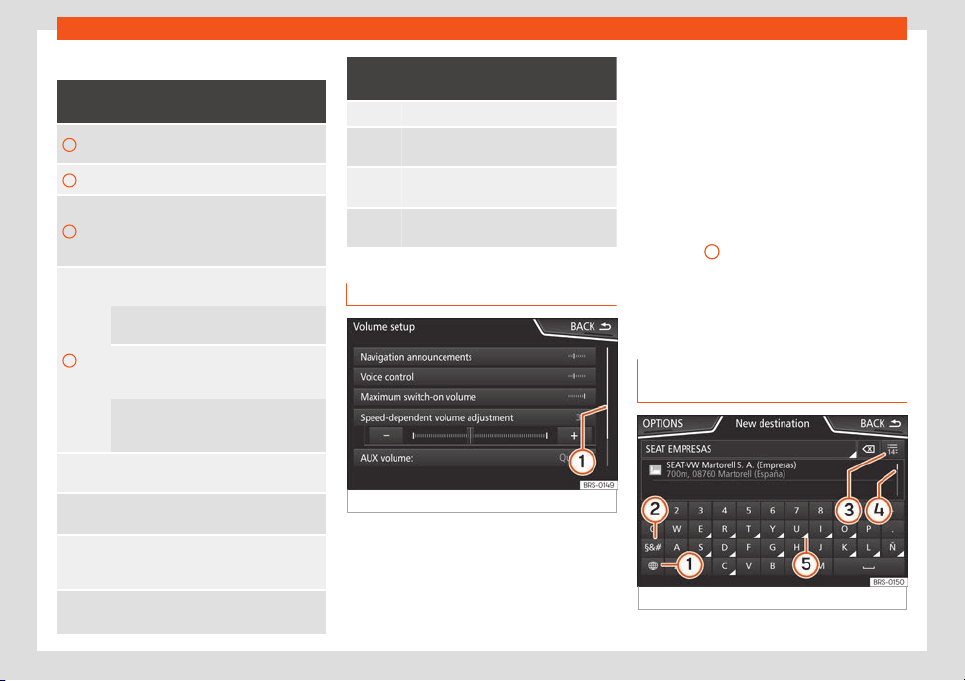
Infotainment System
Overview of screen and function buttons
Display and function buttons: operation
and effect
A
The title bar shows the selected menu
and other function buttons.
B Press it to open another menu.
C
The scroll bar is shown on the right. Scroll
the bar by sliding your finger vertically on
it
›››
page 172, Open list entries and
sear
ch in lists.
D
Movable cursor: Move the cursor by slid-
ing your finger across the screen.
OR: Press a point on the scr
een where
you want the sound to be directed.
Fixed cr
osshair: Press on the arrows to
move the sound around according to your
preferences.
OR: Press the central button to centre the
stereo sound in the centre of the passen-
ger compartment
Press it on some lists to move up a level,
one by one.
BACK
Button to return to the previous menu or
mo
ve up through the folder structur
e.
When pressed, a pop-up window opens
(options window) which displays other
setup options.
/
Some functions are activ
ated or deac-
tivated by pressing this box.
Display and function buttons: operation
and effect
OK Press to confirm an entry or a selection.
×
Press to cl
ose a pop-up window or an in-
put windo
w.
/
Press them to change the setup adjust-
ments one at a time
.
Move the scroll button across the scr
een
by sliding your finger.
Open list entries and search in lists
Fig. 166
Entries on a setup menu list.
The entries on a list can be activated by
pr
essing them on the scr
een or by using the
settings butt
on.
Mark list entries using the set
up butt
on
and open them
●
T
urn
the adjustment knob to search and se-
lect from the list.
●
Press the setup button to activate the
marked entry on the list.
Search lists (scrolling the screen)
The scroll bar is shown on the right and its
size depends on the entries in the list
›››
Fig. 166
1
.
●
On the bar: Pr
ess abo
v
e or bel
o
w the mark
or slide your finger v
ertically o
ver the mark
until you reach the desired position.
Input window with on-screen key-
pad
Fig. 167 Input window with on-screen keypad.
172

Introduction
The on-screen keypad is used for functions
such as ent
ering an memory name
, sel
ecting
a destination addr
ess or ent
ering a sear
ch
t
erm for searching long lists.
The input line with cursor is located in the top
bar of the screen. All inputs are displayed
here.
Input windows for “free text input”
In the input masks for open text, you may en-
ter letters, numbers and characters in any
combination.
Input windows for selecting a saved entry
(e.g. selection of a destination address)
It is only possible to enter a sequence of let-
ters, numbers and characters that matches a
stored entry.
Matches are suggested on the input line
›››
Fig. 167
4
. In the case of compound
names, it is necessary t
o ent
er a space
.
Ov
ervie
w of the function butt
ons*
Function icon and text: operation and ef-
fect
Letters and
digits
Press them to copy them into the input
line
.
1
Press to change the keypad to anoth-
er language. Keypad languages can
be selected from the menu System
settings > Speech.
Function icon and text: operation and ef-
fect
2
Press to show symbols on the keypad.
3
If there are fewer than 99, it shows the
number of entries that can be selec-
ted. Pressing opens the list according
to the entry.
4
Scroll bar, the size of which depends
on the number of matching entries.
5
If the button is held down, special
characters based on that letter are
displayed. Pr
ess the desired charac-
ter to enter it. Some special charac-
ters can be written out instead (e.g.
“AE” for “Ä”).
Space bar
Deletes characters on the input line
from right to left.
Press and hold to del
ete several char-
acters.
BACK Close the input window.
Proximity sensor
3 Valid for: Navi System and Navi System Plus.
The Infotainment system is equipped with an
integr
ated proximity sensor
›››
Fig. 160
11
.
The scr
een s
wit
ches fr
om displ
ay mode t
o
aut
omatic operation when your hand moves
toward it. In operation mode, the function but-
tons are automatically highlighted to facili-
tate their use.
Motion sensors (gesture control)*
3 Valid for: Navi System and Navi System Plus.
Depending on the version, the infotainment
system has motion sensors that can be used
to change cert
ain functions, e.g. next station,
next memory bank, previous track, etc.
●
Press the infotainment button > Set-
tings > Screen > activate/deactivate
proximity sensor.
If the sensors are active, when you move your
hand close t
o the screen the silhouette of a
hand will be displayed in the lower right cor-
ner.
With this function the system switches to the
previous or next station, track, memory bank,
etc., when you move your hand from left to
right, or vice-versa, in front of the screen. An
audible warning also sounds.
173
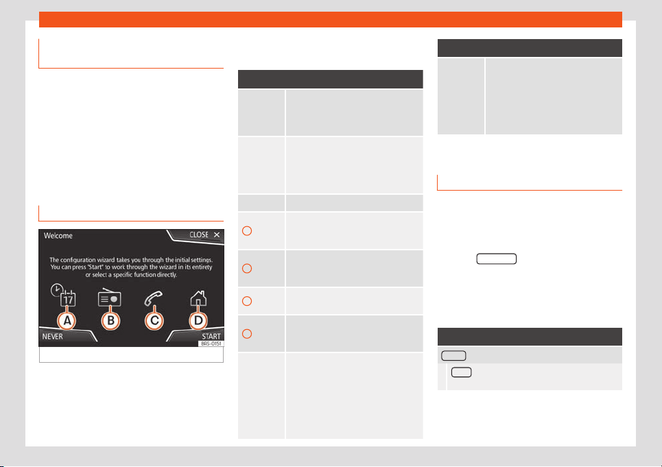
Infotainment System
Additional information and display
options
The displays appearing on the screen may
vary depending on the settings, and may
differ from those described here.
The stat
us bar on the screen can display, for
example, the current time and outside tem-
perature.
All displays can be viewed only after com-
pletely restarting the Infotainment system.
Initial configuration wizard
Fig. 168
Initial configuration wizard
It will help you to set up your Infotainment
syst
em the first time you s
wit
ch it on.
Ev
ery time you s
wit
ch on the Inf
otainment
system, the initial setup screen will appear
›››
Fig. 168 if any parameters have not been
set or if the NEVER function button has not
been pressed.
Function button: function
CLOSE
Closes the Configuration Wizard, and
the main menu or last mode in which
you used the Infotainment system will
appear.
NEVER
Disables the possibilit
y of changing
the settings of the Infotainment sys-
tem. To configure the system go t
o:
System settings and select Con-
figuration wizard.
START Starts up the Configuration Wizard.
A
If the system includes navigation, the
date and time are set automatically
by the GPS.
B
Search and save the radio stations
with the best reception at that time in
all available bands.
C
Link your mobile phone to the Infotain-
ment system.
D
a)
Add your home address using your
current position or by manually enter-
ing an address.
PREVIOUS
NEXT
Previous or ne
xt parameter to config-
ure.
When a parameter has been config-
ured, the only way t
o reconfigure it is
by clicking on it on the main menu, not
by using the Previous/Next buttons.
When you configure a parameter,
will be displayed over it.
Function button: function
FINISH
Once one or more settings have been
applied, finalise the configuration in
the main menu of the wizzard.
If you have not set all the parameters,
the Initial Configur
ation Wizard will
start the next time you turn the Info-
tainment system on.
a)
Only valid for Navi System and Navi System Plus.
Menu and system settings
The settings that can be selected varies de-
pending on the country and the equipment in
question, and on the v
ehicl
e's equipment.
●
Pr
ess the Inf
ot
ainment butt
on
and then
press the SETTINGS
function button.
Pr
ess the function butt
on of the main menu or
the functions f
or which you w
ant t
o change
the settings. All settings ar
e aut
omatically
applied when the menus are closed.
Function button: function
Screen : To change the screen settings.
Menu : To select the main menu display mode
(Mosaic or Carousel).
174
Introduction
Function button: function
Switch off screen (in 10 seconds) : If this function is
active and the infotainment system is not used,
the screen will automatically s
witch off after ap-
prox. 10 seconds. Pressing the screen or pressing
one of the infotainment buttons will turn the
screen on again.
Brightness
: To select the brightness level of the
screen.
Day / Night : To select the type of display (Day,
Night or Automatic).
Touchscreen tone : The confirmation tone when a
function button is pressed is active.
Proximit
y sensor
: The proximity sensors are active.
Also see
›››
page 173, Pr
oximity sensor.
Show clock in standby mode
: In standby mode, the
time is displayed on the infotainment system
screen.
Date and time : Change the time and date settings.
Clock time source : To select the time source (GPS
or manual).
GPS : The time and date can be selected using
the Time zone function button. In this case, the
Time and Date function buttons for manual
entry will not be active.
Manual : The time and date can be set manual-
ly using the Time and Date function buttons.
Time : To set the time manually.
Time zone : To adjust the desired time zone.
Function button: function
Time format : To select the time display format (12
or 24 hours).
Date : To set the current date.
Date format : To select the date display format
(DD.MM.YYYY, YY-MM-DD or MM-DD-YY).
Language : To select the desired language for texts
and phrases in the voice control system.
Additional keypad languages : To select additional key-
board languages.
Units
: To set the units of measurement of the vehi-
cle's displays: distance, speed, temper
ature, volume,
consumption and pressure.
Data transfer for SEAT apps
Data transfer for SEAT apps : This allows data to be
exchanged between the vehicle and SEAT apps.
They are not personal dat
a.
Operation via apps
: Change the level of interaction
with apps.
Deactivate : This limits specific functions that
require a higher level of security.
Confirm : Allows 100% of functions of the app,
and certain specific actions on the Infotain-
ment system have to be confirmed.
All
ow
: Allows all available functions to be exe-
cuted from the app.
Voice control : To change the voice control settings
›››
page 177.
Function button: function
Remove safely : To eject the data medium (SD/USB
card) from the system. After correctly ejecting the
dat
a storage device from the system, the function
button becomes inactive (grey colour).
Factory settings
: When the original factory settings
are restored, all inputs and settings that are made
are deleted, depending on the selected settings.
Bluetooth : To change the Bluetooth
®
›››
page 242
settings.
WLAN
a)
: To change the WLAN access point settings
›››
page 211
.
System information
: Display of the system information
(device number, hardware and softwar
e versions).
Update
: To update the navigation data, do
›››
page 215 No
remove the memory card while
the navigation data are being installed.
Copyright
: Information about copyright.
Configuration wizard : Opens the Infotainment system’s
initial configuration wizard.
a)
Only available for the model: Navi System Plus.
Note
For the proper functioning of the Infotain-
ment system it is important that the date
and time set in the vehicle ar
e correct.
175
Infotainment System
Volume and sound settings
The settings that can be selected varies de-
pending on the country and the equipment in
question, and on the vehicle's equipment.
●
Press the Infotainment button
and then
press the Sound
function button.
●
Press the main menu function button for the
settings that have to be changed. All settings
are applied instantly.
Overview of scr
een and function buttons
Function button: function
Volume : To change the volume settings.
Warnings : To set the playback volume of warn-
ings, such as traffic announcements.
Navigation announcements : To set the playback
volume of audio driving recommendations.
Voice control : To set the playback volume of
voice control.
Maximum switch-on volume : To set the equipment's
maximum switch-on volume.
Speed-dependent volume adjustment
(GALA): To set
the extent to which the volume is adjusted de-
pending on the speed. The volume of the audio
will incr
ease automatically as the speed of the
vehicle increases.
Entertainment fading when parking
: To adjust the
desired reduction in audio volume when ParkPi-
lot is active
.
Function button: function
Entertainment fading (nav. announcements) : Adjusts
the playback volume when the navigator is
speaking.
Volume : To set the playback volume of audio
sources connected via the AUX-IN multimedia
jack (Low, Medium or High). Also see
›››
page 176, Overview of screen and function
buttons.
Bluetooth audio : To set the playback volume of
the audio sources connected by Bluetooth
®
(Low, Medium or High). Al
so see
›››
page 176,
Overview of screen and function buttons.
Equaliser
: To adjust the sound properties.
Balance - Fader : To adjust the sound distribution. The
cursor indicates the current sound distribution in the
passenger compartment. To modify the sound distri-
bution, briefly press on the desired position in the
passenger compartment view or use the arr
ow keys
for a step-by-step modification. To centre sound dis-
tribution in the passenger compartment view, press
the central function button located between the ar-
rows.
Sound focus
: Optimizes the sound in the passenger
compartment.
Subwoofer *: Adjusts the volume of the subwoofer.
Touchscreen tone : The confirmation tone when a func-
tion button is pressed is active.
Disabling voice navigation during calls : During a tele-
phone conversation, audio driving recommendations
will not be given.
Adjust the playback volume of external
audio sour
ces
If you need t
o incr
ease the pl
ayback v
olume
f
or the e
xternal audio source, first lower the
base volume on the infotainment system.
If the sound from the connected audio source
is very low, increase the output volume on
the external audio source. If this is not
enough, change the input volume to medium
or high.
If the sound from the connected external au-
dio source is too loud or distorted, lower the
output volume on the external audio source.
If this is not enough, change the input vol-
ume to medium or low.
176
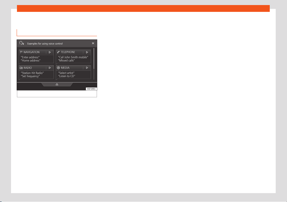
Introduction
Voice control
Ho
w it w
orks
Fig. 169 Voice control: main screen
Many of the radio, media, telephone and nav-
igation functions can be changed by v
oice
commands.
The v
oice contr
ol of the inf
ot
ainment syst
em
will only be av
ailable for the language selec-
ted in System settings
›››
page 174.
●
Voice control settings
›››
page 179.
Start and stop voice control
●
To activate voice control, briefly press the
button on the multifunction steering wheel
or the infotainment system.
●
When activating voice control, a dialogue
start tone will sound and the main voice con-
trol screen will be displayed,
›››
Fig. 169, (the
main screen will appear in the format selec-
ted in Voice control settings
›››
page 179).
The spoken indications guide you through the
following “dialogue”.
●
Speak the desired command and follow the
instructions in the “dialogue”. Often a func-
tion can be activated by different spoken
commands. If in doubt, try speaking a com-
mand or say Help.
●
When an action is taken (e.g., call a con-
tact), the voice control ends automatically
and you must activate it again if you want to
continue with it. There are certain commands
after which the voice control does not end,
and it waits by saying Next command?.
●
To manually end voice control, press and
hold the button until the corresponding
confirmation signal sounds, or briefly press
the button twice, or press the function but-
ton in the upper right corner of the screen.
●
You can also end the voice control by
speaking the following commands: Stop or
Cancel.
Voice control help
It is recommended to listen to the Help the
first time you use the voice control.
●
Activate voice control .
●
Say the command Help to start it in the lan-
guage indicated System Settings, and fol-
low the instructions in the dialogue. The Help
command can also be spoken followed by a
function of the infotainment system, such as
“Help with navigation”.
Interacting with the dialogue mode
Icons in upper left corner:
The system waits for a user's command.
The system has recognised a command
and will act shortly.
The system transmits a spoken com-
mand and confirms the command that
has been given.
The system is in paused mode. (max. 3
minutes).
Hide or show the voice control menu
›››
Fig. 169.
Operation during the dialogue
While the infotainment system transmits a
spoken instruction, the symbol will be dis-
played on the screen.
●
You can stop the speech by pressing the
upper left icon on the screen or button and
voice recognition will resume for the user.
IMPORTANT: The system will ONLY recog-
nize a command when the symbol is
displayed as “active” on the panel or on
the touchscreen.
»
/
177
Infotainment System
If you make a mistake when speaking a com-
mand, or pr
onounce it incompl
et
ely and it
has no eff
ect, you may r
epeat the command.
The symbol
remains activated.
●
Briefly press button to repeat the com-
mand.
Voice control instructions
Follow the instructions shown below for opti-
mal operation of the voice control.
●
Speak slowly and clearly if possible. The
system will not recognise words that are un-
clearly pronounced, or words and numbers
that are missing syllables.
●
Telephone numbers should be spoken digit
by digit, or by blocks units, tens or hundreds.
●
Speak at a normal volume, without exag-
gerated pronunciation or long pauses.
●
Avoid outside and nearby noise (for exam-
ple, conversations inside the vehicle). Close
all doors, windows and the sliding sunroof.
●
Do not direct the air from the outlets to-
wards the roof of the passenger compart-
ment.
●
If you are driving at high speed, talk a little
louder.
By activating voice control the system takes
you to the main screen
›››
Fig. 169, which will
display the contexts in which the system op-
erates and the main commands.
From here you can command the system
based on the context that you want to oper-
ate, or give a voice command directly.
When selecting each of the contexts (Naviga-
tion, Telephone, Radio, Media, Voice control)
a menu will displayed listing the main com-
mands, and providing brief explanations of
how to give each of them, as a help mode.
Voice control (RADIO)
Effect Voice command
LISTEN TO THE RADIO Listen to the radio
SELECT STATION
Station STATION NAME 1
Set station
SELECT FREQUENCY
Frequency 87.9
Set frequency
CHANGE BAND
Band FM
Change band
Voice control (MEDIA)
Effect Voice command
SOURCE SELECTION
Play Jukebox
a)
Listen to CD
MUSIC SELECTION
Select track / album / ar-
tist / genre
Effect Voice command
PLAY SIMILAR TITLES
a)
Play similar titles
a)
Only available for the model: Navi System Plus
Voice control (TELEPHONE)
Effect Voice command
CALL CONTACTS
Call Name Surname
Home
Call Name Surname Mo-
bile
CALL NUMBERS
Call 01234
Call number
CALL LIST
Show all calls
Missed calls
REDIAL Redial
CALL MAILBO
X Call mailbox
SMS Read out text message
SERVICE Breakdown call
INFORMATION Information call
178
Introduction
Voice control (NAVIGATION)*
Effect Voice command
ENTER THE ADDRESS
Enter address
Guide to City, Street,
number
a)
SEARCH FOR SPEC.
DESTINATION
a)
Search for car parks
Search for rest
aurants
near destination
HOME ADDRESS Home address
LAST DESTINATIONS Last destinations
NAVIGATION TO CON-
T
ACTS
Navigate to Name Sur-
name
ROUTE GUID
ANCE
Start route guidance
Route information
a)
Only available for the model: Navi System Plus
V
oice contr
ol
Effect Voice command
VOICE CONTROL
Pardon?
Back
Main menu
Cancel voice control
Pause voice control
Effect Voice command
HELP
Help
What can I say?
VOICE BUTTON
Note
Voice control is not available when parking
Voice control settings
●
Press the infotainment button
> Set-
tings > Voice control.
When cl
osing a menu, the changes will be
made aut
omatically.
Function button: function
Example commands (infotainment system) : Display voice
control examples on the infotainment syst
em screen.
Example commands (instrument cluster)
a)
: Display voice
control examples on the instrument panel.
Voice control session start tone : a signal will sound
when activating voice control. Press to deactiv
ate
the signal.
Voice control session end tone
: a signal will sound when
deactivating voice control. Press to deactiv
ate the
signal.
Function button: function
Input tone in voice dialogue : the input tone to confirm
an order is activated.
End tone in voice dialogue : the end tone to confirm an
order is deactivated.
a)
Available depending on equipment
179
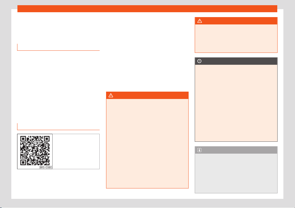
Infotainment System
Connectivity
Dat
a tr
ansf
er
Intr
oduction
This communication can allow data to be
read and/or written.
From the menu SETTINGS > Data trans-
fer for SEAT apps, there is a checkbox t
o
activate/deactivate the function and a drop-
down menu called Operation via apps
which controls the level of interaction be-
tween the apps and the system.
Full Link*
Full Link technology description
Fig. 170 Related video
The Full Link connection is made through a
USB cabl
e
.
The Full Link syst
em brings t
ogether t
echnol
-
ogies that all
ow communication between the
Infotainment System and mobile devices:
●
MirrorLink
®
●
Android Auto™
●
Apple CarPlay™
Interfaces
To access the Full Link system, press the info-
tainment button or press the infotainment
button and then select the Full Link
context.
WARNING
Any applications that are not suitable or
execute incorrectly may cause damage to
the vehicl
e, accidents and serious injuries.
●
SEAT recommends the use of the Apps
that SEAT provides for this vehicle.
●
To make full use of SEAT Apps, you must
activate the option Settings > Data
transfer for SEAT apps.
●
The interaction level of the Apps on the
system must be: Allow.
●
Protect the mobile terminal with its appli-
cations from improper use.
●
Never make modifications to the applica-
tions.
●
Consult the instruction manual for the
mobile terminal.
WARNING
The use of applications while driving can
distract your attention from the traffic. Dis-
tracting the driver in any w
ay can lead to
an accident and cause injuries.
●
Always drive carefully and responsibly.
CAUTION
●
In areas where special regulations apply
or the use of mobiles forbidden, it must be
s
witched off at all times. The radiation pro-
duced by the mobile when switched on
may interfere with sensitive technical and
medical equipment, possibly resulting in
malfunction or damage to the equipment.
●
SEAT cannot be held liable for any dam-
age caused to the vehicle as a result of the
use of applications that are of poor quality
or are defective, the inadequate program-
ming of the applications, the insufficient
coverage of the network, the loss of data
during transmission or the improper use of
mobiles.
Note
●
The use of Full Link technology could in-
crease the amount you pay for data.
●
SEAT r
ecommends having a high battery
charge on the device when connected to
Full Link.
●
SEAT recommends that to use Full Link,
the “Date and time” should be correctly
180
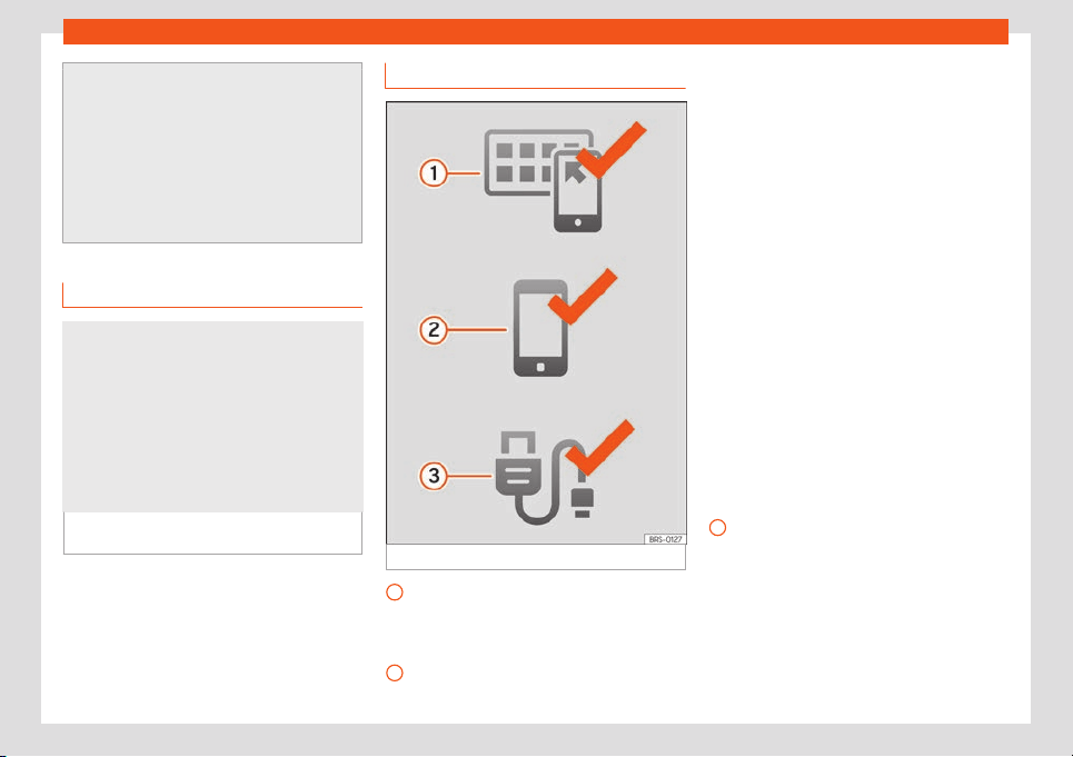
Connectivity
configured. Select Settings > Time and
date.
●
SEAT apps are designed to communicate
with the vehicle and interact with it through
the Full Link connection.
●
You can find fur
ther information on the
technical requirements, compatible devi-
ces, suitable applications and availability
at www.seat.com or at SEAT dealers.
Is Full Link blocked?
Fig. 171
Message on Infotainment system
scr
een.
If your vehicle does not have Full Link, you
can pur
chase it as an accessory at your
SEAT deal
er
›
›
›
Fig. 1
7
1.
Requirements for Full Link
Fig. 172 Full Link Requirements
Full Link Activated: If you do not hav
e
Full Link in your v
ehicl
e you can acquir
e it
as an accessory at your Authorised Serv-
ice
.
Compatibl
e Phones
. Go to the Mirror-
Link
®
, Android Auto™ or Apple CarPlay™
1
2
websites to confirm whether your phone
is compatibl
e with the syst
em.
Mirr
or Link
–
Check smartphone compatibilit
y:
www
.mirr
orlink
.com/phones
–
MirrorLink
®
1.1 or higher
–
Some of the Apps certified by SEAT or
the CCC must be installed in the de-
vice.
Android Auto
–
Check smartphone compatibility. An-
droid Auto™: www.android.com/auto/
–
Android 5.0 (Lollipop) or higher
–
Install Android Auto™ app
Apple CarPlay
–
Check smartphone compatibility. Apple
CarPlay™:www.apple.com/ios/carplay
–
iPhone 5 or higher and iOS 7.1 or higher
–
Turn on the SIRI personal assistant (see
phone settings)
USB cable connecting car to phone:
Use the approved USB cable supplied
with the phone.
3
181
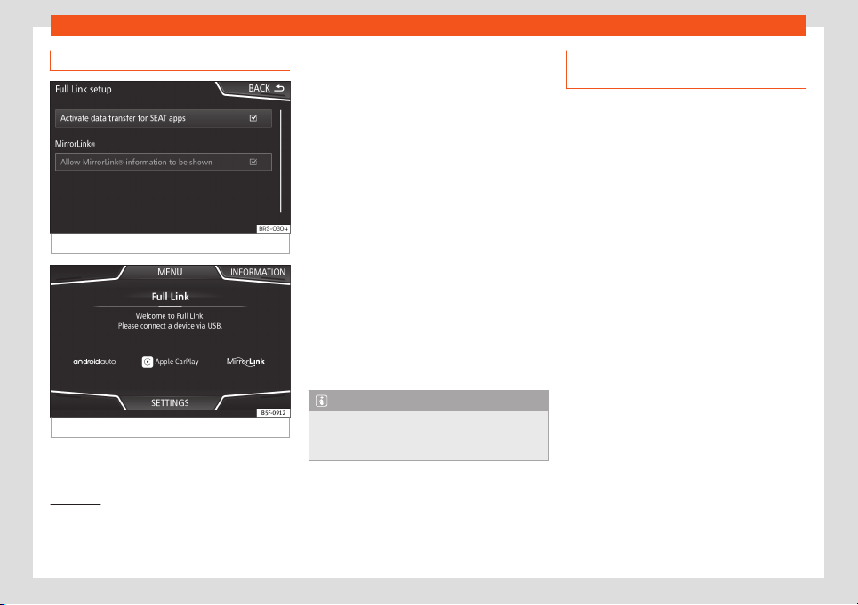
Infotainment System
Activation of Full Link
Fig. 173
Full Link Setup
Fig. 174
Full Link menu
Data connection via Wi-Fi or SIM is not
necessary t
o est
ablish the connection be-
tw
een the smar
tphone and Full Link
.
Dat
a connection via Wi-Fi or SIM is neces-
sary t
o enable all of the app features
1)
.
Proceed as follows to use Full Link:
●
Switch on the Infotainment system
●
Connect the smartphone to the vehicle's
USB port using a USB cable
›››
page 244.
●
In the main menu for the Full Link settings,
select Activate data transfer for
SEAT apps
›››
Fig. 173.
Finally, a message will appear stating that
data transfer will commence when the device
is connected. Please note that data is trans-
ferred over connections between your vehi-
cle and mobile device. Press OK. Once selec-
ted, the technology compatible with your de-
vice can be used.
Note
Depending on your smartphone, it may
have to be unlocked for the connection to
occur
.
What should I do if it does not con-
nect?
Restart the mobile device.
Check the USB cable. Check whether the
USB cable is damaged. Check that neither
connection (USB/micro USB) is damaged or
worn.
Check that the USB por
ts are correctly
connected. Check that the USB port of the
vehicle and the device are not damaged
and/or deteriorated.
●
Clean the USB ports (device and vehicle).
●
Try with another compatible mobile device.
●
Have the USB port replaced at a SEAT au-
thorised service.
●
Have the mobile device repaired or r
eplace
it.
1)
Using the data connection to transfer the
smartphone apps to Full Link may involve addi-
tional charges. Please check the char
ges with
your operator.
182
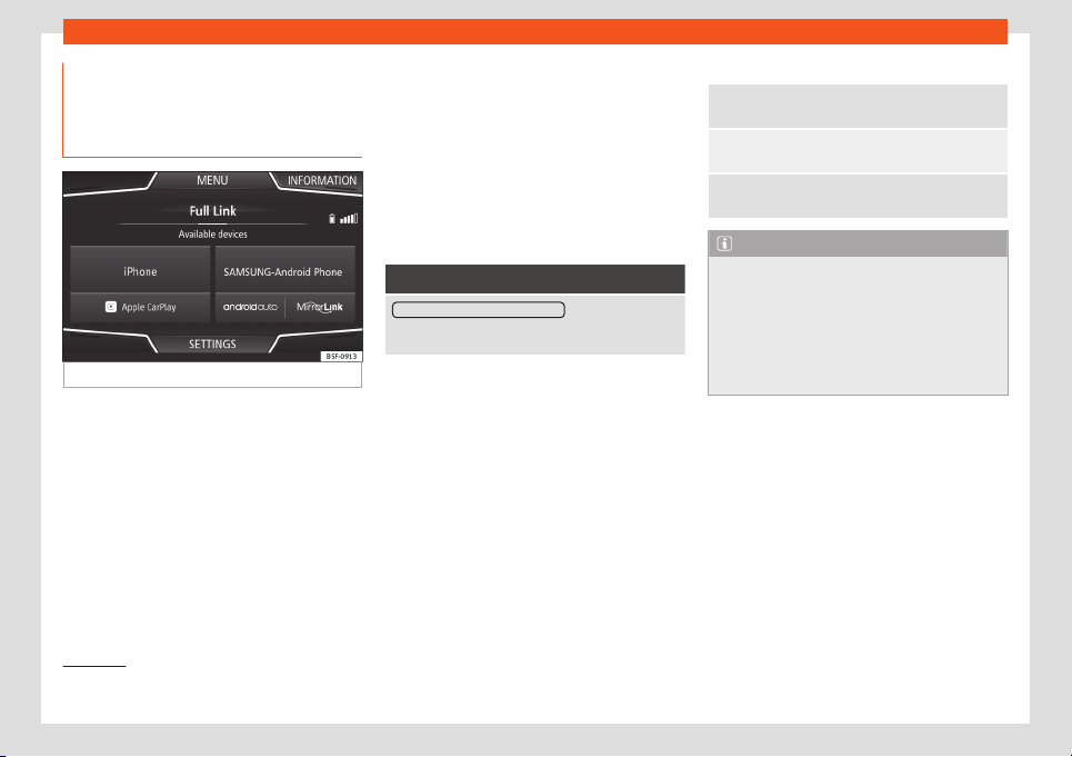
Connectivity
Tethering of portable devices that
suppor
t Mirr
orLink
®
, Andr
oid Aut
o™
and/or Appl
e CarPl
ay™ t
echnolo-
gies
Fig. 175
Full Link menu
When you enter Full Link for the first time, the
t
echnol
ogies av
ail
abl
e f
or pairing the port
a-
ble device are displayed.
Once the device connects via USB, the sys-
tem will offer you the technologies available
for establishing a connection.
In the event of simultaneous connections be-
tween two devices with different operating
systems, a choice will be presented for which
one to make the connection with
›››
Fig. 175.
View of the device list
iPhone™ devices only support Apple Car-
Play™.
There are some Android devices that support
MirrorLink
®
and Android Auto™.
Bear in mind that once the device is connec-
ted it will not be available as an audio source.
Full Link Settings
Function button: function
Activate data transfer for SEAT apps : allows the ex-
change of information between the vehicle and ap-
plications authorised by SEAT.
Last Mode
If the t
el
ephone connection is t
erminat
ed on-
ly by unplugging the cabl
e
, the ne
xt time the
device is connected, the session will start
without the user having to take any action
1)
.
Information
Consult the mobile device manual.
Depends on each technology:
Availability in a country
Third party applications
1.
2.
For further information:
MirrorLink
®
:
www.mirrorlink.com
Apple CarPlay™:
www
.apple.com/ios/carplay
Android Auto™
:
www.android.com/auto
Note
●
In order to use Android Auto™ technology
it is necessary t
o download the Android
Auto™ application, located on Google
Play™.
●
Only compatible applications can be
used, in accordance with the technology
connected.
1)
Unless the device requires the screen to be un-
locked in order to establish the connection.
183
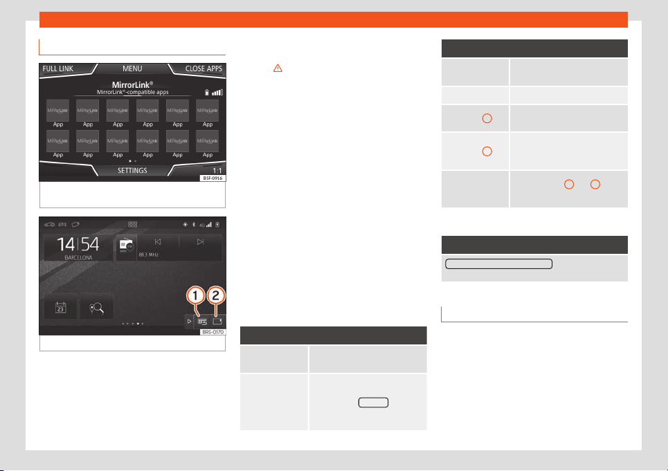
Infotainment System
MirrorLink
®
Fig. 176
Function buttons in the general view
of compatibl
e applications.
Fig. 177 Other MirrorLink function buttons.
MirrorLink
®
is a pr
ot
ocol which enabl
es com-
munication betw
een a de
vice and the Inf
o-
t
ainment system.
This makes it possible to display and operate
content and functions on the device from the
screen of the infotainment system.
To avoid distracting the driver while driving,
only specially adapted applications can be
used
›››
in Full Link technology descrip-
tion on page 180.
R
equir
ements
In or
der t
o use Mirr
orLink
®
, the f
oll
owing re-
quirements must be met:
●
The device must be compatible with Mirror-
Link
®
.
●
Depending on the device that is used, a
suitable application must be installed for the
use of MirrorLink
®
.
Initiating the connection
●
In order to initiate the connection with the
device, just connect it to the Infotainment sys-
tem via the USB cable.
●
A pop-up screen will appear, which will re-
quest that you accept the device.
Function buttons and possible messages
Function button: function
Full Link
To return to the Full Link main
menu.
CLOSE APPS
Press to close the open apps.
Then press the apps to be
closed or the Close all function
button to close all the open ap-
plications.
Function button: function
1 : 1
Press to change to the mobile
device screen.
SETTINGS To open the Full Link setup
›››
Fig. 177
1
Press to return to the MirrorLink
®
main menu.
›››
Fig. 177
2
Press to display all the function
buttons in the lower or upper
right-hand margin of the scr
een.
›››
Fig. 177 /
OR:
Right adjust-
ment button
Allows buttons
1
and
2
to be
hidden or shown.
MirrorLink
®
set
up
Function button: function
Activate MirrorLink pop-up windows : Allows MirrorLink
®
pop-up windows in applications that support it.
Apple CarPlay™*
3 Valid for compatible iPhone™ mobile tele-
phones. Also, iPhone™ mobile tel
ephones only
support Apple CarPlay™
Apple CarPlay™ is a protocol which enables
communication between a device and the in-
fotainment system.
This makes it possible to display and operate
content and functions on the device from the
screen of the infotainment system.
184
Connectivity
Requirements
In or
der t
o use Appl
e CarPl
ay™, the f
oll
o
wing
requirements must be met:
●
Make sure that you do not have Apple
CarPlay™ restricted on your device, at: Set-
tings > General > Restrictions >
CarPlay > ON.
●
The mobile device must be compatible with
Apple CarPlay™.
Initiating the connection
In order to initiate the connection with the de-
vice, just connect it to the Infotainment sys-
tem via the USB cable.
●
A pop-up screen will appear, which will re-
quest that you accept the device.
●
If you start the session using Apple
CarPlay™ technology, it will not be possible
to pair another device via Bluetooth
®
. The fol-
lowing message will appear in the main
Phone menu:
Please disconnect Apple CarPlay
first to connect a different mo-
bile phone.
Holding down the button will start the
Apple™ voice “engine”.
To return to the basic contents of the Infotain-
ment system, press the SEAT icon.
Android Auto™*
3 Valid for compatible Android mobile phones.
Android Auto™ is a protocol which enables
communication betw
een a device and the in-
fotainment system.
This makes it possible to display and operate
content and functions on the device from the
screen of the infotainment system.
Requirements
In order to use Android Auto™, the following
requirements must be met:
●
The mobile device must be compatible with
Android Auto™.
●
The Android Auto™ application should al-
r
eady be downloaded and installed on the
mobile device.
Initiating the connection
In order to initiate the connection with the de-
vice, just use the USB cable to connect it to
the infotainment system and follow the in-
structions on the device to be paired.
●
The first connection to Android Auto™ must
be done while the vehicle is stationary.
●
Once the first pop-up window about ac-
cepting data transfer between the car and
the device has been accepted, a message
will appear requesting that you check your
mobile device for the confirmations needed
to pair it with the Infotainment system.
●
If you are starting the session using Android
Auto™ technology, the device also automati-
cally connects to the Infotainment system via
Bluetooth
®
and it will not be possible to pair
another device via Bluetooth
®
.
Holding down the button will start the
Android™ voice “engine”.
To return to the basic contents of the Infotain-
ment system, press the button.
Note
Some devices require a change in the USB
connection mode in order to use Android
Auto™.
●
Make sure that your de
vice is in “Media
Transfer Protocol (MTP)” mode before it is
connected to the Infotainment system.
Note
Android Auto™ requires the use of Google™
services, as well as certain basic applica-
tions of the Android system.
●
Make sur
e that you always have Google™
services updated in order to use this tech-
nology.
185
Infotainment System
Frequently asked questions about
Full Link
What connection method is used?
USB Cable.
Will the USB cable be supplied with the vehicle?
No. The USB cabl
e supplied with the device should
be used.
Is it possible to navigat
e?
Navigation is possible in each one of the Full Link
technologies if the technology is avail
able in your
country and if you have the Navigation app.
What is the difference between using the Full Link
system navigator (via a device) instead of anoth-
er navigator?
Advant
ages: Daily updates.
Issues: data consumption, reception problems.
Can I send voice messages?
With certified applications, you can reply, not send.
What applications will be visible while driving?
Depending on the technology:
– for MirrorLink
®
: Apps certified by SEAT and the
CCC,
– for Android Auto™: Apps selected by Google™,
– for Apple CarPlay™: Apps selected by Apple™.
Where can I find compatible Apps?
Compatible apps are listed at the following links:
www
.mirrorlink.com/
www.android.com/auto/
www.apple.com/ios/carplay/
Where can I download the apps?
On Google Play™ for Android Auto™/MirrorLink
®
and
on Appl
e Store™ for Apple CarPlay™.
If Full Link stops working, where can I go to repair
it?
If the problem is in the car, you should go to the deal-
er
. If the problem is in the mobile device, you should
see your mobile telephone vendor.
Will WhatsApp be certified?
The WhatsApp situation depends on the technology.
Is MirrorLink
®
availabl
e in my country?
Yes, MirrorLink
®
is available in all countries and re-
gions where SEAT is located.
What are the differences between MirrorLink
®
,
Android Auto™ and Apple CarPlay™?
MirrorLink
®
is not compatible with Android Auto™ and
Apple CarPlay™, as they are different technologies.
They all coexist in Full Link, although Android Auto™ is
designed for mobile devices with the Android™ oper-
ating system, and Apple CarPlay™ for iPhone.
Can MirrorLink
®
be installed in a previous SEAT
model?
No, it is not possible
.
Where can I find more information about Full
Link?
If you have any questions, please see our Innova-
tion/Connectivity
sections on our website:
www.seat.es or www.seat.com or e-mail seat-re-
SEAT Media Control*
Intr
oduction
Fig. 178 Related video
The SEAT Media Contr
ol
1)
app can be used
t
o r
emot
ely oper
at
e some partial functions in
R
adio, Media and Navigation mode. Informa-
tion can be exchanged between a device
and the Infotainment System.
1)
Availability depends on the country.
186
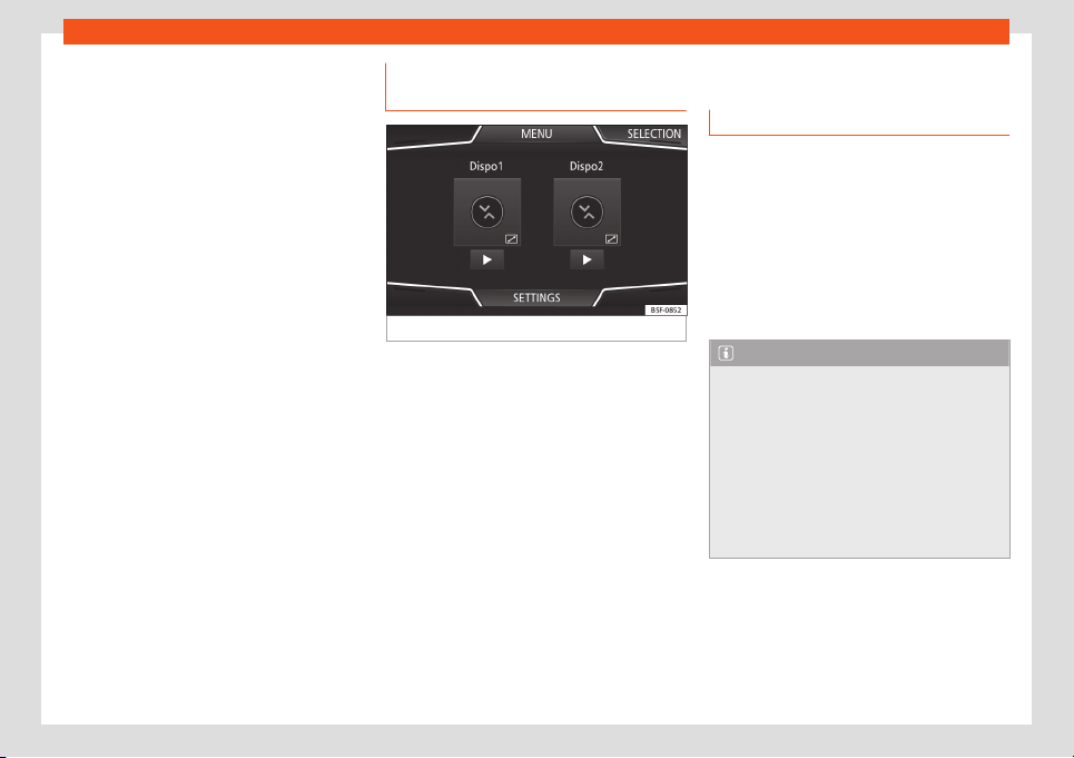
Connectivity
The functions are operated by means of a
T
abl
et or partially by a mobil
e phone
.
Oper
ating r
equir
ements:
●
A tablet or mobile phone.
●
The app must be available on the corre-
sponding device.
●
There must be a WLAN connection between
the Infotainment System and the device. Se-
lect Menu > Media > Settings > WLAN >
Share connection over WLAN > Config-
uration.
Make sure that data transfer for apps is acti-
vated:
●
From the SETTINGS menu > Data trans-
fer for SEAT apps, there is a checkbox to
activate/deactivate the function and a drop-
down menu called Operation via apps
which controls the level of interaction be-
tween the apps and the system . Select Menu
> Settings > Data transfer from mo-
bile devices.
You can obtain information about technical
requirements on the SEAT website or at SEAT
dealerships.
Telephone functions do not form part of this
app.
Data transmission and control
functions
Fig. 179
SEAT Media Control Main menu
With SEAT Media Contr
ol
you can oper
at
e
the Inf
ot
ainment Syst
em from other places in
the vehicle in Radio and Media modes and,
depending on the country and the equip-
ment, you can exchange the following infor-
mation between a device and the Infotain-
ment System:
●
Navigation destinations.
●
Traffic information.
●
Social media contents.
●
Audio transmission.
●
Vehicle data.
●
Location-specific information, for example,
POIs.
WLAN access point*
Introduction
The Infotainment System can be used to
share a WLAN connection with up to 8 devi-
ces
›››
page 188, Configur
ation for sharing
a connection over WLAN.
The Infotainment System can also use the
WLAN hotspot of an external device to pro-
vide Internet to the devices connected to the
hotspot (WLAN client)
›››
page 188, Config-
ure Internet access.
Note
●
Data transmission may incur charges.
Due to the high volume of data e
xchanged,
SEAT recommends the use of a flat rate tar-
iff for data transmission. Mobile phone op-
erators can provide the relevant informa-
tion.
●
The exchange of data packages may
generate additional costs, depending on
your mobile phone rate, particularly if you
are abroad (for example, roaming rates).
187

Infotainment System
Configuration for sharing a con-
nection o
v
er WLAN
Establishing the connection with the wire-
less network (WLAN)
●
Press the Infotainment button
and then
press the Settings menu.
●
Activate the wireless network. To do so,
press the WLAN function button.
●
Activate the wireless network (WLAN) on the
device that is to be connected. If necessary,
refer to the manufacturer’s instruction man-
ual.
●
Activate the mobile device assignment on
the Infotainment System. To do so, press the
Enable WLAN connection butt
on and acti-
vate the checkbox.
●
Enter and confirm the network key dis-
played on the device.
The following settings can also be made on
the menu Share connection:
●
Security level: WPA2 encryption auto-
matically generates a network key.
●
Network key: Network key automatically
generated. Press the function button to man-
ually change the network key. The network
key must have a minimum of 8 characters
and a maximum of 63.
●
SSID: WLAN Network name (maximum of
32 characters).
●
Do not send network name (SSID):
Activate the checkbox to deactivate the visi-
bility of the wireless (WLAN) network.
The wireless (WLAN) connection is establish-
ed. To complete the connection, it may be
necessary to enter other data into the device.
Repeat this process to connect other devices.
Wi-Fi Protected Setup (WPS)
1)
Wi-Fi Protected Setup can be used t
o cr
eat
e
a cipher
ed l
ocal wir
el
ess network quickly and
simply.
●
Establish the connection with the wireless
network (WLAN)
›››
page 211.
●
Press the WPS button on the WLAN router
until the warning light on the router starts
flashing. If the WLAN router does not support
WPS the network must be configured man-
ually.
●
OR: Press and hold the WLAN button on the
WLAN router until the WLAN light on the router
starts flashing.
●
Press the WPS button on the WLAN device.
The wireless (WLAN) connection is establish-
ed.
Repeat this process to connect other devices.
Configure Internet access
The Infotainment System can use the WLAN
hotspot of an e
xt
ernal de
vice t
o est
ablish an
int
ernet connection.
E
stablishing the connection with the wire-
less network (WLAN)
●
Activate and check the wireless hotspot on
the external device. If necessary, refer to the
manufacturer’s instruction manual.
●
Press the Infotainment button and then
press the Settings menu; OR access Media
or SEAT Md. Ctrl. and press the SETTINGS
menu.
●
Press on the menu WLAN > Enable WLAN
connection and check the verification box.
●
Press the Find function button and select
the device you want from the list.
1)
This function depends on the equipment and
the country in question.
188

Connectivity
●
If necessary, ent
er the netw
ork k
ey of the
de
vice in the Inf
ot
ainment Syst
em and con-
firm with OK.
Manual settings:
●
To manually enter the network settings of
an external (WLAN) device.
The wireless (WLAN) connection is establish-
ed. To complete the connection, it may be
necessary to enter other data into the device.
Note
Due to the large number of devices on the
market, it is not possible to guarantee fault
-
free operation of all functions.
189
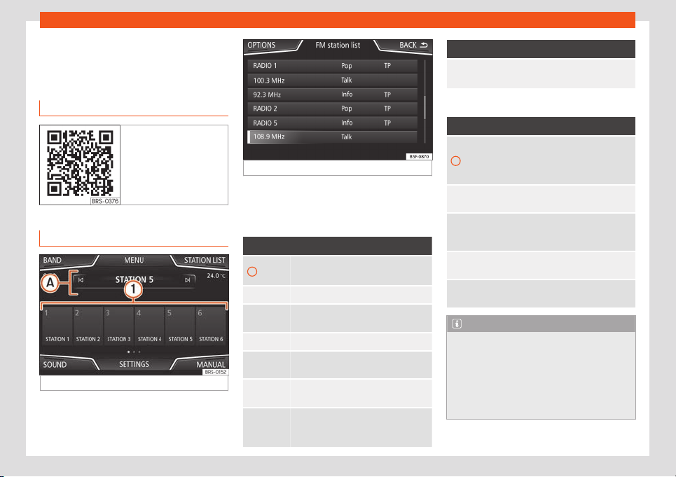
Infotainment System
Operating modes
R
adio
R
el
at
ed video
Fig. 180 Radio mode
RADIO main menu
Fig. 181 RADIO main menu.
Fig. 182 Radio mode: station list (FM).
Press the infotainment button t
o open the
R
adio
main menu
›
›
›
Fig. 181
.
RADIO main menu function buttons
Function button: function
1
Memory keys (1 to 18 memories, 3
banks (screens)
›››
page 193)
BAND Select the band.
S
TATION
LIST
List of radio station that can be tuned.
MANUAL Selecting the fr
equency manually.
VIEW
Selecting the information shown on the
screen. Only available in DAB mode.
SETTINGS
Settings menu f
or the current frequen-
cy band.
/
Previous or next station that is stored or
on the st
ation list. See Settings
›
›
›
page 196
.
Function button: function
Scan
Stops the station search (visible only if
it is running
›››
page 196).
Indications and possible icons
Display: Meaning
A
Frequency or name of the station or
radio text. The name of the radio sta-
tion and the radio t
ext will only be dis-
played if RDS is active.
RDS off
The RDS radio data service is deacti-
vated.
TP
Traffic information can be retrie
ved:
select Radio > Settings >
Traffic programme (TP).
No stations with traffic news are av
ail-
able.
The radio station is stored on a memo-
ry butt
on.
Note
●
The AM and DAB bands will be available
according to countries and/or equipment.
In this case
, the BAND function button will
not be displayed.
●
Being underground, in tunnels, in areas
with tall buildings or mountains can inter-
fere with the radio reception.
190
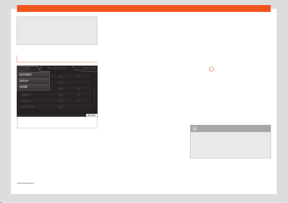
Operating modes
●
Foil or metal-coated stickers attached t
o
the windows may affect reception on vehi-
cles with a window aerial.
●
Radio stations are responsible for the
content of the information they transmit.
Radio data services RDS (FM band)
Fig. 183 Standard representation: FM station
listing menu
The RDS (Radio Data System) or radio data
service off
ers additional FM inf
ormation such
as the displ
ay of the st
ation name
, aut
omatic
st
ation tracking (AF), texts broadcast by radio
(Radio text), traffic announcements (TP) and
the type of station (PTY).
Depending on the country and the equip-
ment in question, RDS can be deactivated in
the FM Settings menu
›››
page 196.
In general, no radio data services are avail-
able without RDS.
Station name and automatic station track-
ing
If the RDS function is available, the names of
the stations can be displayed on the RADIO
main menu and on the Station list .
FM stations temporarily transmit other con-
tent on different regional frequencies under
the same name (for example, Station 3).
In general, automatic station tracking takes
charge of switching to the frequency with the
best reception of the station that is tuned at
any given time, while driving. However, this
may cause a regional broadcast to be inter-
rupted.
Automatic frequency switching and automat-
ic station tracking can be deactivated in FM
Settings
›››
page 196.
Set a station name
In certain cases the station name is exces-
sively long. This text can be locked / unlocked
by pressing on the name of the station for
about 3 seconds until an audible warning is
heard (a point will flash to the right and left of
the station name).
Radio text
Some stations that have RDS transmit addi-
tional information in text, the so-called radio
text.
The radio text is displayed in the upper half of
the screen above the memory buttons
›››
Fig. 181
A
.
The r
adio t
e
xt displ
ay can be deactiv
at
ed in
the
Settings
›››
page 196.
Order of the station list
The stations available at any given time are
displayed on the station list screen (STA-
TIONS function button). This list can be sorted
by broadcast group, genre or alphabetically
›››
Fig. 183.
Note
The RDS functionality will be limited in
some countries for infrastructure reasons,
and traffic announcements (TP), aut
omatic
station tracking (AF) and station type (PTY)
may not be available.
1)
1)
Depends on the market and unit in question.
191

Infotainment System
Digital radio mode (DAB, DAB + and
DMB audio)*
Fig. 184
Display of memory buttons in DAB
mode
.
Fig. 185
Station information display in DAB
mode
.
The DAB radio tuner supports the DAB, DAB +
and DMB audio tr
ansmission st
andar
ds.
In Eur
ope
, digit
al r
adio is transmitted over
band III frequencies (from 174 MHz to 240
MHz).
The frequencies are called “channels” and
have an abbreviation (eg 12 A).
In a channel, several available DAB stations
are grouped together in an “ensemble”.
Starting the Digital radio mode
●
In the RADIO main menu, press the BAND
function button and select D
AB
.
The l
ast D
AB st
ation that w
as sel
ect
ed will be
pl
ayed, if it can still be tuned in that location.
The selected DAB station is shown in the top
bar of the screen. The selected station en-
semble is shown below
›››
Fig. 184.
Additional DAB stations (Secondary Serv-
ice Components)
Some DAB stations temporarily or perma-
nently offer additional stations (for example,
for the transmission of sporting events).
DAB stations containing additional stations
are identified on the station list by the symbol
.
Select additional stations
Press the name of the main station on the
DAB main menu to select an additional sta-
tion. Or, select the additional station from the
station list.
On the DAB main menu, the name of the ad-
ditional tuned station is displayed next to the
abbreviated name of the main DAB station.
Additional stations can not be saved.
Automatic station tracking
DAB radio is not currently available every-
where. DAB radio mode displays the areas
without DAB coverage .
If the DAB station that is being listened to can
no longer be tuned (e.g. there is no DAB cov-
erage), the infotainment system tries to find
and tune the same station in the different
available frequency bands. If the station can
not be found again, the radio sound is muted.
Automatic station tracking can be activated
in the DAB Settings in the following modes
›››
page 197:
●
DAB - DAB station tracking: The radio tries
to tune to the same station on an alternative
DAB frequency. To allow station tracking,
both DAB stations need to broadcast the
same station identification, or to signal the
other corresponding DAB station through
DAB.
●
DAB - FM Automatic switching: The radio
tries to tune to the same station in the FM fre-
quency band. To allow station tracking, the
DAB station and the FM station need to
192
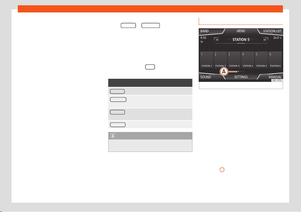
Operating modes
broadcast the same station identification, or
t
o signal the other corr
esponding FM st
ation
thr
ough D
AB. When the corr
esponding FM
st
ation has been found, “FM” is displayed be-
hind the name of the station. If the corre-
sponding DAB station becomes available
again, it returns to DAB mode after a while
and the “FM” identification is concealed.
●
Switch to a similar station: This allows
service providers to indicate alternative sta-
tions with similar content. In this way, if the ra-
dio loses coverage of a DAB station and does
not find an alternative FM or DAB frequency, it
is possible to tune to a station with similar
content.
Radio text
Some stations transmit additional text infor-
mation, the so-called radio text.
Radio text is displayed in the upper half of the
screen above the memory buttons
›››
Fig. 184
or on the Station Information or Radio text
screens of the Display menu
›››
page 193.
The radio text display can be deactivated in
the DAB Settings
›››
page 197.
Slideshow
Some stations transmit additional visual infor-
mation in the form of images.
These images are displayed as a slideshow
on the Stations
or Slidesho
w
screens of the
Screen menu
›
›
›
page 193
.
The slidesho
w can be displ
ayed in full scr
een
by pressing on the current image.
Screen Menu
The function buttons refer to the menu that is
displayed when the View
button is pressed
›
›
›
Fig. 184
.
Function button: function
Preset list : Viewing the preset buttons
›››
Fig. 184.
Station List : Simultaneous display of radio text and
slideshows instead of memory keys
›››
Fig. 185.
Radio text : The radio text is displayed instead of the
memory buttons.
Slideshow : Slideshows are shown in full screen mode.
Note
Not all DAB stations broadcast radio text
and slideshows.
Memory buttons
Fig. 186
RADIO main menu.
In the R
adio main menu, you can store sta-
tions fr
om all av
ail
abl
e fr
equency w
ave-
lengths on the numbered function buttons.
These function buttons are called “memory
buttons”.
Storing the station on the memory buttons
See: Preset stations
›››
page 195.
Change the memory bank (screens)
●
Move your finger over the screen from left
to right or vice-versa.
●
OR: Press one of the function buttons
›››
Fig. 186
A
»
193
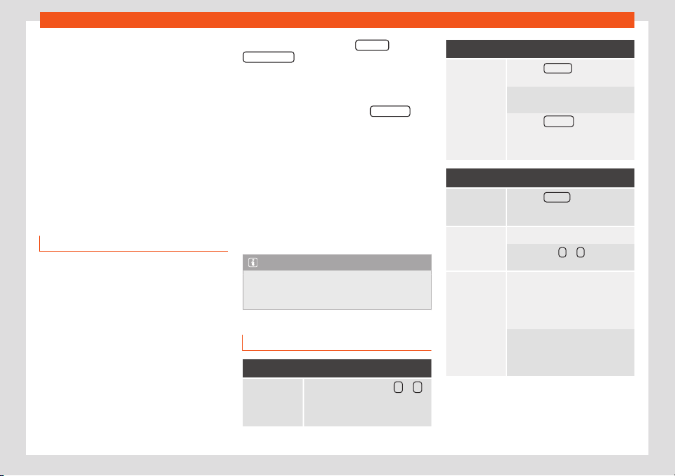
Infotainment System
Selecting the station from the memory
butt
ons
●
Pr
ess the memory butt
on corr
esponding t
o
the desir
ed st
ation.
The stored stations can only be played by
pressing the corresponding memory button
provided it can be received at your current
location.
Storing the station logo on the memory
buttons
Saved stations can be assigned logos
›››
page 194.
Save station logos
Save automatically (only in FM and DAB
mode)
When a st
ation is sav
ed, the st
ation l
ogo is
aut
omatically assigned.
If ther
e ar
e 2 or more logos in the database,
there is the option to choose the appropriate
one.
Saving manually
Station logos can be imported from a com-
patible data medium (for example, memory
card or memories with a USB port).
●
Press the function button Settings
and then
St
ation l
ogos .
●
Press the stored station button that you
w
ant t
o use t
o st
or
e a st
ation l
ogo.
●
Select the source in which the logo has
been memorized (for example, SD Card 1
). It is
r
ecommended that the l
ogos shoul
d be put in
the r
oot dir
ect
ory of the memory unit.
●
Sel
ect the station logo.
●
Repeat the process to assign other logos;
press the infotainment key to return to the
Radio main menu.
●
If you want to change the logo of a memory
button where a button has already been
saved, it must first be deleted from the button
in question.
Note
Not all stations are in the database, so it is
not always possible to assign logos auto-
matically.
Select, tune and save stations
Selecting stations
Select the sta-
tion using the
arrow keys
Press the function button or
›››
Fig. 181.
This switches between stations
available for tuning
›››
page 196.
Selecting stations
Selecting sta-
tions from the
station list
Press the Stations
›››
Fig. 181 func-
tion button to open the st
ation list.
Browse the list and tune to the sta-
tion you want by pressing it.
Press the BACK
›››
Fig. 182
function button to close the list. If it
is not used, the list will cl
ose auto-
matically after a while.
Manually tuning a station frequency
Display the
frequency
band
Press the Manual function button
›››
Fig. 181.
Changing the
frequency step
by st
ep
Turn the adjustment knob.
OR: Pr
ess the +
or – keys on the
dial displ
ayed on the scr
een.
Quickly tr
ack
the fr
equency
band
Pr
ess and hol
d one of the arr
ow
buttons on the l
eft of the multifunc-
tion steering wheel. Releasing the
butt
on switches to the next radio
station that can be tuned.
OR: Keep your finger on the scroll
button in the frequency band and
move your finger to mo
ve the but-
ton.
194

Operating modes
Manually tuning a station frequency
Hide the fre-
quency band
Briefly press the settings button.
Selecting a station using the mem-
ory button also ends the manual
selection of frequencies. If no oper-
ations are performed, the frequen-
cy band is hidden after a while.
Presetting stations
Saving the sta-
tion that is be-
ing listened to.
Press and hold the desir
ed preset
button
›››
Fig. 181
until an audible
signal is heard.
The tuned station is stored on a
preset button.
Saving a sta-
tion from the
stations list
Press the St
ations
›››
Fig. 181 func-
tion button to open the st
ation list.
The stations that are already stor-
ed on a memory key are marked on
the station list with the symbol
››
›
Fig. 182.
Select the desired station by
pressing and holding it down on
the screen. A screen opens f
or sav-
ing the station on the memory but-
tons.
Press the memory key where the
station will be saved.
A sound is heard and the station is
saved on the memory button. Re-
peat the process to continue sav-
ing other station on the list.
Presetting stations
Delete preset
stations
The Settings menu can be used
to delete all of the saved stations
together
, or separately
›››
page 196.
Automatic playback (SCAN)
When automatic playback is active, all tune-
able stations in the selected frequency band
are pl
ayed for approximately 5 seconds
each.
Start and end automatic playback
Start automatic
playback
Press the Settings function button
and then select Scan .
End automatic
playback
Press the function button to
stop automatic playback on the
station that is being played.
Automatic playback also ends
when a station is selected man-
ually using the memory buttons,
or when the screen is changed.
Traffic information (TP)
It is only possible for traffic information to be
tr
ack
ed with the TP function if the st
ation in
question can be t
uned. St
ations with the tr
af
-
fic information function are shown on the RA-
DIO main menu and on the station list with
the symbol TP
›››
Fig. 181 and
›››
Fig. 182.
Some stations without their own traffic infor-
mation support the TP function by broad-
casting traffic announcement from other sta-
tions (EON).
Activating and deactivating the TP func-
tion
●
In the Settings (FM, AM, DAB) menu,
activate or deactivate the
Traffic programme (TP)
function button by
pr
essing it
›
›
›
page 196
.
Activ
e TP function and st
ation selection
Traffic announcements are played in Audio
mode.
If a station without the TP function in FM mode
is selected, the radio tries to find stations with
this function in the background. If none are
found, it will be displayed half way up the left
hand side of the screen
.
In AM mode or in Media mode, a traffic sta-
tion is automatically tuned in the background
as long as there is one available. Depending
on the situation this operation may take some
time.
»
195
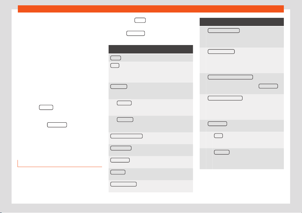
Infotainment System
Incoming traffic announcement
In Audio mode
, tr
affic announcements ar
e
pl
ayed aut
omatically when they ar
e
r
eceived.
While the traffic announcement is playing, a
pop-up window is displayed and the radio
switches, if necessary, to the traffic informa-
tion station.
Media mode is interrupted and the volume is
set as adjusted
›››
page 176.
The volume of the traffic announcement can
be changed with the volume control . The
modified volume remains as set for subse-
quent warnings.
●
Press the Cancel
function button to end the
curr
ent tr
av
el w
arning. The TP function r
e-
mains activ
e
.
●
OR: Press the Deactivate
function button to
end the curr
ent tr
affic announcement and
deactiv
at
e the
TP
function permanently. The
function can be r
eactivated in the Settings
menu.
Settings (FM, AM, DAB)
FM settings
Sel
ect the
FM
fr
equency band by pr
essing
the inf
ot
ainment key .
OR: Press the BAND
function button and se-
l
ect the
FM
fr
equency band.
Pr
ess the SETTINGS
function button to open
the FM settings menu.
Function button: function
Sound : Sound settings
›››
page 176.
Scan : Automatic playback (SCAN function). When
automatic playback is active, each of the tuneable
stations in the selected frequency band are played
for approximately 5 seconds each
›››
page 195.
Seek mode : To set the settings for the arrow buttons
and . The setting applies to all frequency bands
(FM, AM and DAB).
Preset list : The arrow keys are used to switch be-
tween all of the saved stations in the selected
frequency band.
St
ation List
: The arrow keys are used to switch
between all of the tuneable stations in the selec-
ted fr
equency band.
Traffic programme (TP)
: The TP function (tracking of
traffic information stations) is active
›››
page 195.
Delete presets
: To erase all or some of the preset sta-
tions.
Station logos : To assign or delete manually the sta-
tion logos saved in the memory keys
›››
page 194
.
Radio text
: The radio text is active
›››
page 191, Radio
text
.
Advanced settings
a)
: Radio data services (RDS) set-
tings.
Function button: function
Autostore station logos
a)
: The stations saved on the
memory buttons are automatically assigned ra-
dio st
ation logos if they are available in the info-
tainment system. Also see
›››
page 194.
Station logo region
a)
: This allows the vehicle's re-
gion (country) to be selected. This optimizes the
automatic assignment of station logos. The op-
tion also allows the system to select the region
automatically.
Automatic frequency control (AF)
a)
: Automatic sta-
tion tracking is active. When there is no check in
check bo
x , the function button RDS regional
will be inactive (grey).
Radio data system (RDS)
a)
: The Radio Data System
(RDS) is deactivated
››
›
page 191. If there is no
check in check box , the traffic information
station (TP), radio text, station name and pro-
gram type functions will not be available.
RDS regional
a)
: Set the RDS automatic station
tracking
›››
page 191.
Fixed
: Only alternative frequencies of the
set station with an identical region program
are set.
Aut
omatic
: It always changes to the frequen-
cy of the set station that has the best signal
at the time, even if a regional broadcast that
is in pr
ogress is interrupted.
a)
This depends on the country and unit in question.
AM settings
Sel
ect the
AM
fr
equency band by pr
essing
the inf
ot
ainment key .
196
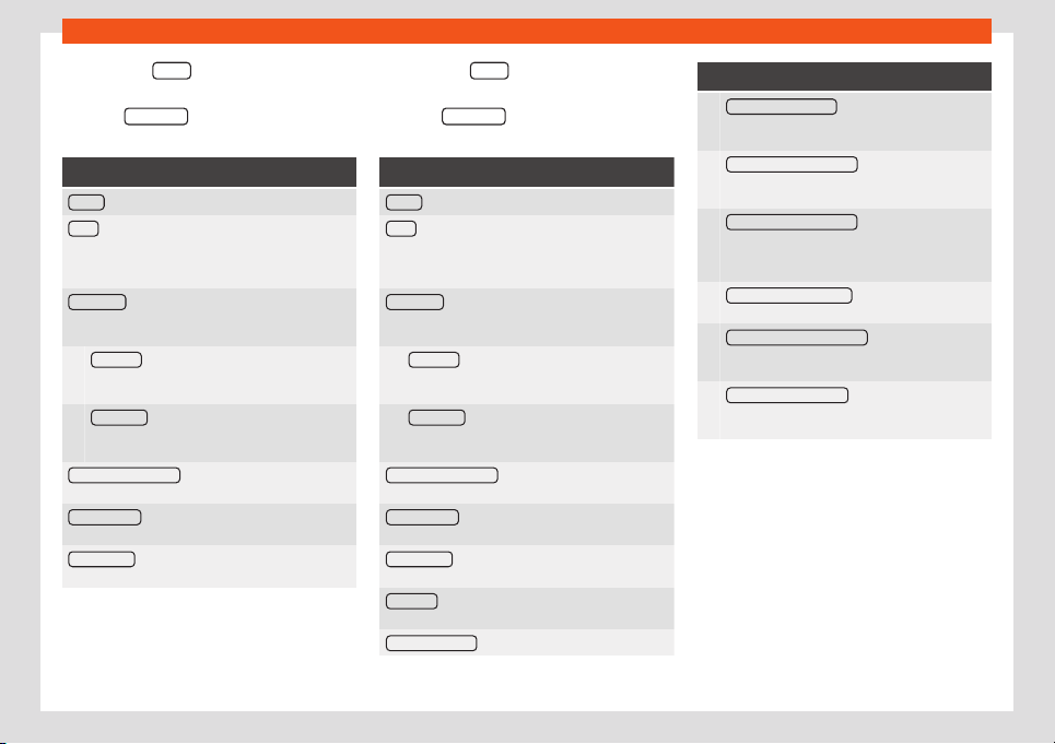
Operating modes
OR: Pr
ess the BAND
function button and se-
l
ect the
AM
fr
equency band.
Pr
ess the SETTINGS
function button to open
the AM settings menu.
Function button: function
Sound : Sound settings
›››
page 176.
Scan : Automatic playback (SCAN function). When
automatic playback is active, each of the tuneable
stations in the selected frequency band are played
for approximately 5 seconds each
›››
page 195.
Seek mode : To set the settings for the arrow buttons
and . The setting applies to all frequency bands
(FM, AM and DAB).
Preset list : The arrow keys are used to switch be-
tween all of the saved stations in the selected
frequency band.
St
ation List
: The arrow keys are used to switch
between all of the tuneable stations in the selec-
ted fr
equency band.
Traffic programme (TP)
: The TP function (tracking of
traffic information stations) is active
›››
page 195.
Delete presets
: To erase all or some of the preset sta-
tions.
Station logos : To assign logos to stations stored on
memory buttons
›››
page 194.
DAB settings
Sel
ect the
D
AB
fr
equency band by pr
essing
the inf
otainment button .
OR: Press the BAND
function button and se-
l
ect the
D
AB
fr
equency band.
Pr
ess the SETTINGS function button to open
the DAB settings menu.
Function button: function
Sound : Sound settings
›››
page 176.
Scan : Automatic playback (SCAN function). When
automatic playback is active, each of the tuneable
stations in the selected frequency band are played
for approximately 5 seconds each
›››
page 195.
Seek mode : To set the settings for the arrow buttons
and . The setting applies to all frequency bands
(FM, AM and DAB).
Preset list : The arrow keys are used to switch be-
tween all of the saved stations in the selected
frequency band.
St
ation List
: The arrow keys are used to switch
between all of the tuneable stations in the selec-
ted fr
equency band.
Traffic programme (TP)
: The TP function (tracking of
traffic information stations) is active
›››
page 195.
Delete presets
: To erase all or some of the preset sta-
tions.
Station logos : To assign logos to stations stored on
memory buttons
›››
page 194.
Radio t
ext
: The radio text is active
›››
page 191, Radio
text
.
Advanced settings
: DAB services settings.
Function button: function
Autostore station logos
a)
: Station logos are as-
signed automatically when the radio stations ar
e
stored on the memory buttons
›››
page 194.
DAB traffic announcements
: DAB traffic announce-
ments are played in the same way as TP traffic
announcements in any equipment mode.
Other DAB announcements : DAB announcements
(news, sports information, weather, warnings,
etc.) ar
e played while the DAB Radio mode is ac-
tive.
DAB - DAB station tracking
: Automatic station track-
ing within the DAB frequency range is active.
Automatic D
AB - FM switching
: Switching to the FM
frequency band is permitted for automatic sta-
tion tracking.
S
witch to a similar station
: This allows service pro-
viders to indicate alternative stations with similar
cont
ent.
b)
a)
This depends on the country and unit in question.
b)
Only available for the model: Navi System Plus
197
Infotainment System
Media
Intr
oduction
Fig. 187 Related video
Audio or image sources containing files in dif-
f
er
ent media ar
e kno
wn as “
media sour
ces
”.
These audio files can be played through the
corresponding players or the infotainment
system's audio inputs.
Only supported files are displayed and
played. Other files are ignored.
Copyright
Consider the legislation on the intellectual
property of audio and video files.
Note
●
MPEG-4 HE-AAC audio coding technolo-
gy and patents are licensed by Fraunhofer
IIS.
●
This pr
oduct is protected by certain Mi-
crosoft Corporation copyright and proper-
ty rights. The use or commercialization of
technology of this type outside the config-
uration of this product, without a licence
from Microsoft or an authorised Microsoft
branch is prohibited.
●
The infotainment system only pl
ays com-
patible undamaged audio files; other files
are ignored.
●
Check the list of compatible devices on
the SEAT website.
Requirements for data media and files
The factory-fitted CD and DVD players are
cl
ass 1 accor
ding t
o DIN IEC 76 (CO) 6 / VDE
0837.
Only st
andar
d 12 cm CD/D
VDs and 32 mm x
2
4 mm x 2.1 mm or 1.4 mm memory cards can
be inserted in the infotainment system.
Any playable file formats on the list will here-
inafter be known as “audio files”. A CD con-
taining these types of audio files is called an
“audio data CD”.
198

Operating modes
Valid for the model: Navi System Plus
Data media
Playback requirements
Audio files Video files
Optical discs:
– Audio CD (up t
o 80 min).
– Standard video DVD and compatible audio DVD.
– CD-ROM, CD-R, CD-RW with audio data up to a max. of 700
MB (megabyte) with the ISO 9660 Level 1 and 2, Joliet or UDF
1.02, 1.5, 2.01 file system.
– DVD +/- R / RW up to a maximum of 4.7 GB and double layer
DVD up to max. 8.5 GB in the Joliet file system (single session
only); UDF.
Memory cards:
– SD and MMC in the file system must be FAT12, FAT16, FAT32 or
VFAT (max 2 GB).
– SDHC (max 32 GB) and SDXC (max 2 TB) with the exFAT and
NTFS file systems.
USB data media:
– Devices with USB 2.0 and 3.0 specifications.
– FAT16, FAT32, exFAT and NTFS file system.
– Different generations of iPods™
a)
, iPads™
a)
and iPhones™
a)
.
– MTP players with the trademarks “PlaysForSure” or “Ready-
ForVista”..
Jukebox (internal SSD memory).
– Digital Audio Specification.
– MP2 (.mp2) and MP3 (.mp3) files with transfer
rates from 32 t
o 320 kbit/s or variable transfer
rate.
– WAV files (.wav).
– WMA files (.wma) up to 10 mono / stereo without
copy protection and transfer rates of up to
384kbit/s.
– AAC files (.m4a, .m4b and .aac) without copy
protection.
– OGG-Vorbis 1 (.ogg) files with transfer rates of
up to 256kbit/s.
– FLAC files (.flac).
– Matroska container files (.mka).
v Maximum resolution 720 x 576 pixel and 25-30fps
(frames per second).
– MPEG-1 and MPEG-2 formats
(.mpg, .mpeg, .m2ts, .avi and .mkv) with a maximum
resolution of 352x288 pixels.
– ISO MPEG-4 f
ormat (.mp4, .m4v, .avi, .mov, .3gp
and .mkv).
– MPEG-4 ASP DivX format 4, 5 and 6 (.avi, .divx
and .mkv).
– Xvid MPEG-4 format (.avi and .mkv).
– MPEG-4 H.264 format:
(.mp4, .m4v, .mov, .3gp, .avi, .m2ts, .mkv, .flv, .f4v
and .webm).
– Windows Media Video 9 format
(.wmv, .asf, .mp4, .m4v, .mov, .3gp and .avi).
– MJPEG format (.avi, .mov, .mp4 and .m4v).
– Theora format (.ogv).
– Playlists in the M3U, PLS, ASX and WPL formats.
– Playlists must not exceed 20 kB or more than 1000 entries.
– File names and rout
es that do not exceed 256 characters.
– On DVD, a maximum of 1000 files per medium and directory.
– On memory cards, a maximum of 4000 files and a maximum of 1000 files per directory.
– On the Jukebox (SSD), a maximum of 3000 files.
Playback of audio files through the AUX-IN jack. – The external audio source must meet a series of playback conditions
›››
page 208.
Playing audio files via Bluetooth
®b)
. – The external media player must be compatible with the A2DP Bluetooth
®
profile
›››
page 208.
Playing audio files over WLAN. – The external audio source must meet a series of playback conditions
›››
page 211
a)
iPod™, iPad™ and iPhone™ are protected trademarks of Apple Inc.
b)
Bluetooth
®
is a r
egist
er
ed tr
ademark of Bluet
ooth
®
SIG, Inc.
»
199

Infotainment System
Valid for the model: Media System Plus/Navi System
Data media Requirements for playing audio files
Optical discs:
– Audio CD (up to 80 min).
– CD-ROM, CD-R, CD-RW with audio data up to a max. of 700 MB (megabyte) with
the ISO 9660 Lev
el 1 and 2, Joliet or UDF 1.02, 1.5, 2.01 file system.
Memory cards:
– SD and MMC in the file system must be FAT12, FAT16, FAT32 or VFAT (max 2 GB).
– SDHC (max 32 GB) and SDXC (max 2 TB) with the exFAT and NTFS file systems.
USB data media:
– Devices with USB 2.0 and 3.0 specifications.
– FAT16, FAT32, exFAT and NTFS file system.
– Different generations of iPods™
a)
, iPads™
a)
and iPhones™
a)
.
– MTP players with the trademarks “PlaysForSure” or “ReadyForVista”..
– Digital Audio Specification.
– MP2 (.mp2) and MP3 (.mp3) files with transfer rates from 32 t
o 320 kbit/s or varia-
ble transfer rate.
– WAV files (.wav).
– WMA files (.wma) up to 10 mono / stereo without copy protection and transfer rates
of up to 384kbit/s.
– AAC files (.m4a, .m4b and .aac) without copy protection.
– OGG-Vorbis 1 (.ogg) files with transfer rates of up to 256kbit/s.
– FLAC files (.flac).
– Playlists in the M3U, PLS, ASX and WPL formats.
– Playlists must not exceed 20 kB or more than 1000 entries.
– File names and rout
es that do not exceed 256 characters.
– On memory cards, a maximum of 4000 files and a maximum of 1000 files per di-
rectory.
Pl
ayback of audio fil
es thr
ough the AUX-IN jack
.
– The e
xt
ernal audio sour
ce must meet a series of playback conditions
›››
page 208.
Playing audio files via Bluet
ooth
®b)
.
– The external media player must be compatibl
e with the A2DP Bluetooth
®
profile
›››
page 208.
Pl
ay audio files through WLAN.
– The external audio source must meet a series of pl
ayback conditions
›››
page 211
a)
iPod™, iPad™ and iPhone™ are protected trademarks of Apple Inc.
b)
Bluetooth
®
is a r
egist
er
ed tr
ademark of Bluet
ooth
®
SIG, Inc.
R
ead and bear in mind the instruction manual
f
or the external data storage device.
Limitations and indications
Dirt, high temperatures and mechanical
damage can cause data media to fail. Con-
sider the indications provided by the manu-
facturer of the data media.
Quality differences between data media pro-
duced by different manufacturers can cause
playback interference.
Consider copyright legislation!
The configuration of data media or of the
equipment or programs used for recording
may cause some tracks or data media to be
unreadable. On the Internet, for example, can
be found information about the best way to
record audio files or data media (compres-
sion rate, ID3 tag, etc.).
The reading speed can vary considerably
depending on the size, the usage status
200
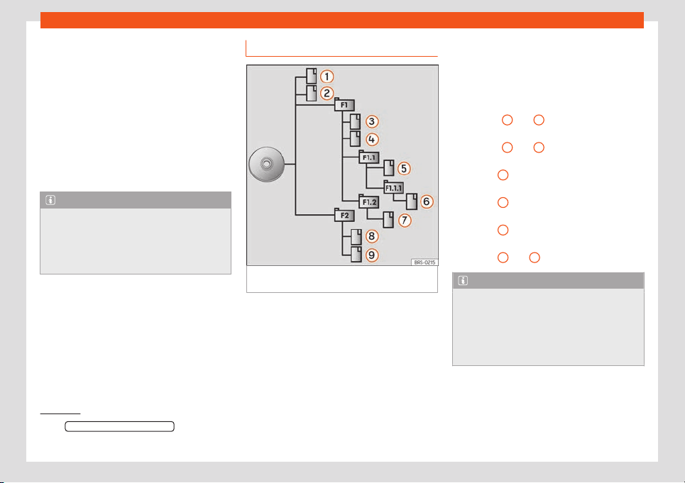
Operating modes
(copying and deleting processes), the struc-
t
ur
e of the f
ol
ders and the t
ype of fil
es of the
dat
a media used.
Playlists only establish a certain playback
order. The files are not saved in them. Play-
lists cannot be played if the files on the data
media are not saved to the path to which the
playlist refers.
A cover can only be displayed when the
name starts with “Cover”, “Folder” or “Al-
bum”.
Note
●
Do not use memory card adaptors, USB
extension cords or USB hubs!
●
SEAT assumes no liability f
or any deterio-
ration or loss of files on data storage devi-
ces.
Playback order of files and folders
Fig. 188
Example of the structure of an audio
dat
a CD
.
The audio files
st
or
ed on dat
a media ar
e
oft
en arr
anged by fil
e folders
and playlists
to establish a certain playback order.
Depending on their name on the data media,
tracks, folders and playlists are ordered nu-
merically and alphabetically.
The illustration shows an example of a con-
ventional audio data CD, containing tracks
, folders and subfolders
›››
Fig. 188.
In this case the tracks will be played as fol-
lows
1)
:
Tracks
1
and
2
in the root directory
(R
oot) of the CD
T
r
acks
3
and
4
in the first F1 f
ol
der of
the CD r
oot dir
ect
ory
T
r
ack
5
in the first subf
ol
der
F1.
1 of f
ol
d-
er
F1.
Track
6
in the first subf
ol
der
F1.
1.
1
of
subf
older F1.1
Track
7
in the second subf
ol
der F1.
2 of
f
ol
der
F1
T
rack
8
and
9
in the second f
ol
der F2
Note
●
The playback sequence can be modified
by selecting the different playback modes
››
›
page 202.
●
Playlists do not play automatically, they
have to be selected directly from the track
selection menu
›››
page 205.
1.
2.
3.
4.
5.
6.
1)
The Mix/repeat including subfolders function must
be active in the Media settings menu
›››
page 214
.
201
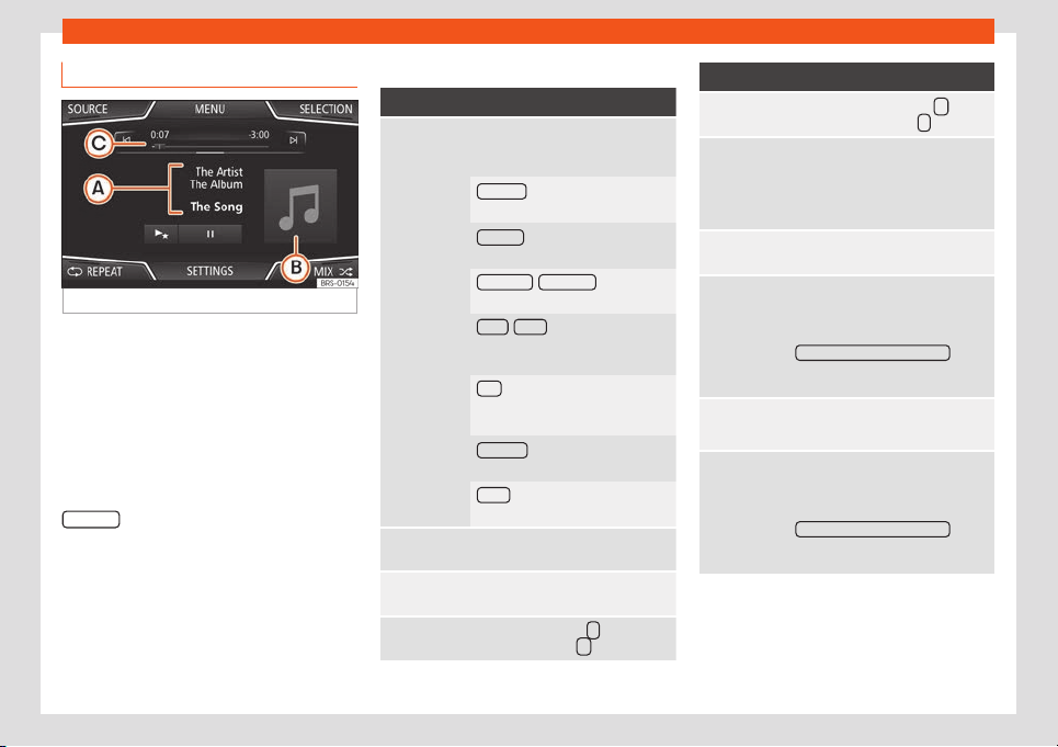
Infotainment System
MEDIA main menu
Fig. 189
MEDIA main menu.
Using the Media main menu, diff
er
ent media
sour
ces can be sel
ect
ed and pl
ayed.
●
Pr
ess the infotainment button to open
the Media
›››
Fig. 189main menu.
It will continue playing the last media source
selected from the same point.
The media source being played is indicated
on the dropdown list when pressing the
SOURCE
function button
›
›
›
Fig. 189
.
If ther
e is no av
ail
able media source, the Me-
dia main menu is displayed.
MEDIA main menu function buttons
Function button: function
SOURCE
The media source that is being
played. Press to select another me-
dia source.
JUKEBO
X
a)
: Internal hard drive
(SSD)
›››
page 209.
CD/DVD
a)
: Internal CD and DVD
drive
›››
page 206
.
SD CARD 1
, SD CARD 2 *: SD memo-
ry card
›››
page 207.
USB 1 , USB 2 *: External data stor-
age device connected to the USB
port
››
›
page 207.
AUX
: External audio source con-
nected to the AUX-IN multimedia
socket
›››
page 208
.
BT AUDIO
: Bluetooth
®
audio
›››
page 208.
WLAN *: External audio source con-
nected by WLAN
›››
page 211
SELECTION
Depending on the l
evel, track list,
folders or source.
/
Changes track in Media mode or
fast forward/rewind.
Playback stops. The
function
button changes to .
Function button: function
Playback is resumed. The func-
tion button changes to .
a)
Play similar tracks.
Creates a virtual playlist that in-
cludes tracks with a similar rhythm
t
o the one being played if available
using Gracenote
®
.
SETTINGS
Opens the menu Media Set-
tings.
REPEAT
Repeats all the tracks that are on
the same memory level as the track
being played at that moment. If in
the Media Settings menu the
Mix/R
epeat including subfolders
option
is enabl
ed, it al
so includes the sub-
f
ol
ders.
REPEAT
R
epeat the curr
ent tr
ack.
MIX
Random playback of tracks that are
at the same memory level as the
current track. If in the
Media Set-
tings menu the
Mix/Repeat including subfolders
option
is enabled, it also includes the sub-
folders.
a)
Only available for the Navi System Plus model.
202
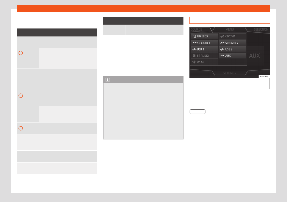
Operating modes
Indications and symbols of the MEDIA
main menu
Display: Meaning
A
Information about the artist name, al-
bum name and song title.
Audio CD: track information if availa-
bl
e via Gracenote
®a)
. If no data is
availabl
e, it only displays Track and
the corresponding order number.
B
Album cover.
The system prioritizes the display as
follows:
1st Co
ver embedded in the file(s).
2nd Image in the file folder.
3rd Image provided by the Grace-
note
®
database
a)
4th Icon of the connected device.
If playing a video file, by pressing the
icon (cover) it can be played on full
screen.
C
The playing time so far and time re-
maining in minutes and seconds.
RDS off
b)
The RDS radio data service is deacti-
vated. The RDS can be activat
ed in
the FM settings menu.
TP
b)
The TP function is active and can be
t
uned in.
b)
There is no traffic news station avail
a-
ble.
Display: Meaning
b)
DAB not available.
a)
Gracenote
®
is a database available on the Infotain-
ment syst
em hard drive that contains information on
the tracks of different artists and albums. In order for
the user to benefit from the functions offered by
Gracenote
®
, the tracks must contain the artist and/or
album data (only available for the model: Navi Sys-
tem Plus.
b)
Depends on the market and unit in question.
Note
●
When the media source is inserted, play-
ing will not start aut
omatically; it is neces-
sary for the user to select the source. Nor
will the media source change when it is
ejected.
●
In order to see the different covers inside
of the same album/folder, make sure that
the tracks contain different information
about the Artist or Album in its metadata. If
not, you will see the same cover for all of
tracks contained in the same album/folder.
Switching the Media source
Fig. 190
MEDIA mode: switching media
sour
ce
.
●
Lower the base volume on the Infotainment
syst
em.
●
Fr
om the
Media
main menu, pr
ess the
SOURCE
function button
›
›
›
Fig. 190
and se-
l
ect the desir
ed media sour
ce.
●
OR: from the Media main menu, press the
Infotainment button repeatedly to cycle
through the available media sources.
In the pop-up window, the Media sources not
selected are shown as deactivated (in grey).
When a Media source that has already been
played is selected again, playback is re-
sumed from the point at which it was stop-
ped.
»
203

Infotainment System
Note
The Media source can be changed in the
Track list view: select
Media > View.
Changing track in the MEDIA main
menu
Fig. 191
MEDIA main menu.
The tracks of the Media source that is being
list
ened t
o can be changed successiv
ely us-
ing the arr
o
w butt
ons.
The arr
ow buttons cannot be used to exit a
playlist or start the playback of a playlist.
Both actions have to be performed manually
from the track selection menu
›››
page 205.
Control through the MEDIA main menu
Action Function
Briefly press the func-
tion button once.
At the start of the current
track. If the track has
been played for less than
3 seconds, it r
eturns to
the start of the previous
track.
Press the function but-
ton
twice in a row.
If the track has been
played for more than 3
seconds, it returns to the
start of the previous track.
If the first track is being
played, pressing the but-
ton goes back to the last
track on the data media
that is being played.
Briefly press the func-
tion button once.
To the next track. It
changes the last track to
the first track on the data
media that is being
played.
Pr
ess and hold function
button
.
Rewind.
Press and hold function
button .
Fast forward.
Slide your finger hori-
zontally over the screen.
Change t
o the previ-
ous/next track, with the
same playback times as
changing tracks with the
keys
or .
Selecting an album by cover
Fig. 192
Selection by cover.
Clicking on the current cover
›
›
›
Fig. 191
1
will display all of the album covers available
in the activ
e Media sour
ce
›
›
›
Fig. 192
.
It is possibl
e to browse through all the albums
by sliding the covers right or left, by using the
bottom horizontal scroll bar, or by using the
settings button.
The cover selection view closes after approx-
imately 5 seconds of inactivity and the Media
main menu is displayed again.
204
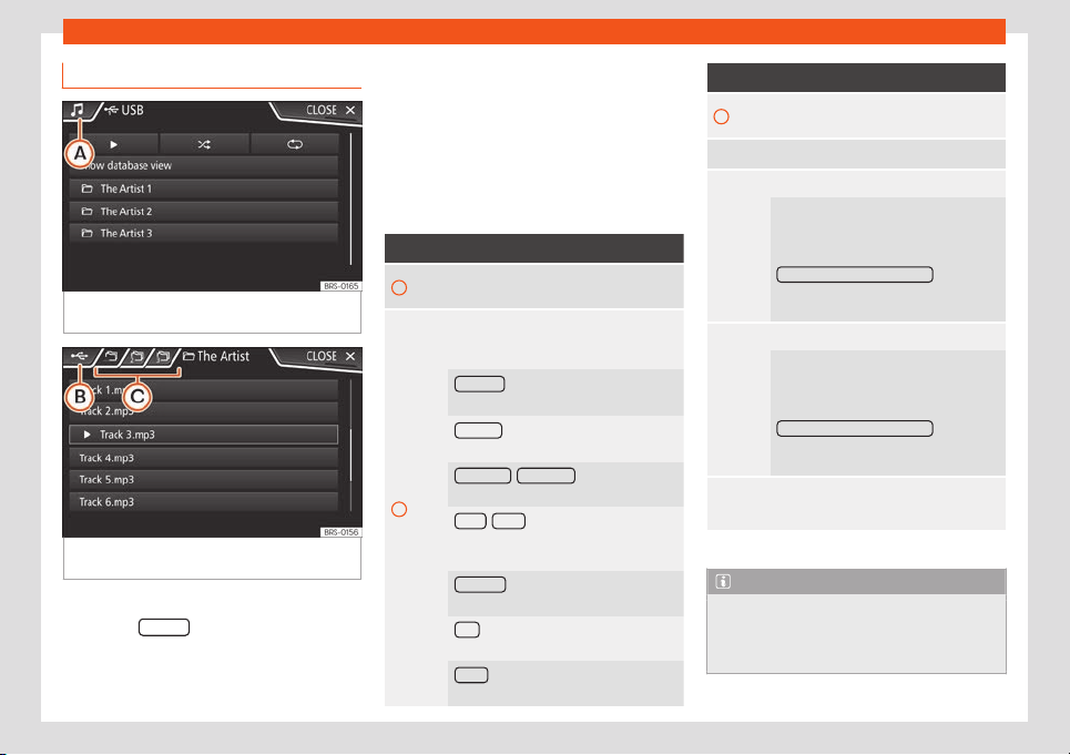
Operating modes
Selecting a track from a track list
Fig. 193
Media Mode: list of folders of a Media
sour
ce
.
Fig. 194 Media Mode: list of tracks of a Media
sour
ce
.
Open a list of tracks
●
Press the SELEC
T
function button on the
MEDIA main menu
›
›
›
Fig. 191
t
o open the
tr
ack list. The tr
ack that is playing is highligh-
ted
›››
Fig. 194.
●
Search the track list and press the track
you want.
If there is track information available, the
track (on audio CDs) or the file name (MP3) is
displayed instead of Track + num.
Overview of the function buttons in the
track list
Function button: function
A
Open the Sources menu. Select anoth-
er Media source by pressing.
B
Indicates the media source being ex-
plored. If pressed, it goes to the root of
the device shown on the icon.
JUKEBOX
a)
: Internal hard disk of the info-
tainment system (SSD)
››
›
page 209.
CD/DVD
a)
: Internal CD and DVD drive
›››
page 206
.
SD CARD 1
, SD CARD 2 *: SD memory
card
›››
page 207.
USB 1 , USB 2 *: External data storage de-
vice connected to the USB port
›››
page 207
.
BT AUDIO
: External Media Player con-
nected via Bluetooth
®
›››
page 208.
AUX : Audio source connected to the
AUX-IN socket
›››
page 208.
WLAN *: External audio source connec-
ted by WLAN
›››
page 211
.
Function button: function
C
Press the function button to open the top
folder of the Media source.
Start playback of the first tr
ack.
Repeat all tracks.
Repeats all the tracks that are on the
same memory l
evel as the track being
played at that moment. If in the Media
Settings menu the
Mix/R
epeat including subfolders
option is
enabled, it also includes the subfolders
›››
page 214.
Random play.
Includes all the tracks that are on the
same memory level as the track being
played at that moment. If in the Media
Settings menu the
Mix/R
epeat including subfolders
option is
enabled, it also includes the subfolders
›››
page 214.
CLOSE
×
To close the tracks list.
a)
Only available for the model: Navi System Plus.
Note
Tracks, folders and playlists can also be
selected by turning the setting button, and
they can be played or opened by pressing
it.
205
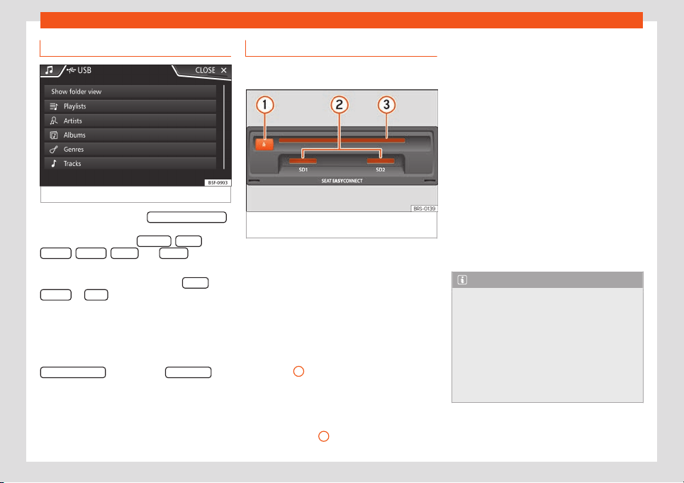
Infotainment System
Data bank view
Fig. 195
Media Mode: data bank view
On the track list, click the Sho
w dat
abase vie
w
option. The content of the current Media
sour
ce will be list
ed by Pl
aylists
, Artists ,
Albums , Genr
es
, T
racks
and Videos
›››
Fig. 193.
When sel
ecting one of the f
ol
ders Artists
,
Albums or T
itles
, a search button is displayed
in the upper right corner (magnifying gl
ass)
that all
o
ws sear
ching within the sel
ect
ed cat
-
egory
›››
page 172, Input window with on-
screen keypad.
To return to the folder view, press the
Show folder view
option on the SELEC
TION
menu.
Insert or remove a CD or DVD
3 The DVD drive is only available for model: Navi
System Plus
Fig. 196
Slots for data storage devices in the
gl
o
v
e compartment.
The driver should refrain from operating the
unit whil
e the v
ehicl
e is in motion. Insert or
change the dat
a st
or
age de
vice before mov-
ing off!
The CD and DVD drives can play audio CDs
and DVDs and audio data CDs and DVDs.
Insert a CD or DVD
●
Insert a CD or DVD into the slot
›››
Fig. 196
3
with the printed side facing up-
w
ar
ds, until the equipment inserts it aut
omati-
cally.
Ejecting a CD or D
VD
●
Pr
ess butt
on
1
.
●
The CD or D
VD in the driv
e will be e
ject
ed
and must be r
emo
v
ed within approximately
10 seconds.
If the CD is not removed within 10 seconds, it
is automatically retracted for security rea-
sons without activating the CD mode.
Unreadable or defective CD or DVD
If the data on an inserted CD or DVD cannot
be read or a defective CD or DVD is inserted,
the corresponding warning appears on
screen.
Depending on the equipment, unreadable
CDs or DVDs are automatically ejected 3
times and reinserted to start another three
read attempts before this indication is dis-
played.
Note
●
Uneven road surfaces and strong vibra-
tions can cause pl
ayback to jump.
●
When the temperature inside the equip-
ment is too high, loading and playback of
CDs and DVDs is disabled.
●
If after inserting a number of different or
DVDs and receiving the CD or DVD drive
error, every time, contact a specialised
workshop.
206
Operating modes
Inserting or ejecting a memory
car
d
Depending on the features and the country,
the vehicle may have one or two slots for SD
car
ds.
Inserting a memory card
Insert the compatible memory card, with the
cut corner first and the contacts facing down,
into slot
›››
Fig. 196
2
, until it clicks into
place.
Removing a memory card
The inserted memory car
ds must be pre-
pared for removal.
●
From the main Media menu, press the
SETTINGS
button to open the Media Set-
tings menu or pr
ess the inf
ot
ainment butt
on
and then pr
ess
Settings, t
o open the
System settings menu.
●
Press the Remove safely
function button. A
dr
opdo
wn menu appears with the f
oll
o
wing
options: SD1 Car
d, SD2 Car
d*, USB1 and
USB2*. Pressing the corresponding function
button disables it.
●
Press the inserted memory card. The mem-
ory card “jumps” to the eject position.
●
Remove the memory card.
External data storage device con-
nected to the USB port
Depending on the features and the country,
the vehicle may have one or two USB con-
nections
›››
page 244.
Where this manual refers to external data
storage devices, this means USB mass stor-
age devices containing supported audio files,
such as MP3 players, iPods™ and USB sticks.
Only supported audio files are displayed and
played. Other files are ignored.
Further operation of the external data medi-
um (changing track, selecting tracks and
playback modes) is described in the appro-
priate chapters of this manual
›››
page 198.
Instructions and restrictions
Compatibility with Apple™ devices and other
media players depends on the unit.
The USB port supplies the usual USB volt-
age of 5 volts for a USB connection.
External hard disks larger than 32 GB must be
reformatted for the FAT32 file system in some
circumstances. You will find the necessary
software and information on the Internet.
Take into account all other instructions and
limitations regarding requirements for media
sources.
iPod™, iPad™ and iPhone™
Depending on the country and equipment,
iPods™, iPads™ or iPhones™ can be connec-
ted via the device's own USB cable t
o the ve-
hicle’s USB port and used as audio sour-
ces.
After connecting an iPod™, iPad™ or iPhone™,
the list views specific to the iPod™ are dis-
played at the top selection level ( Play-
lists, Artists, Albums, Tracks,
Podcasts, etc.).
Possible error messages after connecting
external data media
Error message
Cause and actions to
take
Source is not
supported.
It is not possible to play the
e
xternal dat
a media or es-
tablish communication with
the adapter cable that is
used.
Check that the e
xternal data
media is connected and op-
erates correctly.
If possible, updat
e the exter-
nal data media software.
Device not re-
sponding.
Communication interrupted.
Check that the external data
media is connect
ed and op-
erates correctly.
»
207
Infotainment System
Error message
Cause and actions to
take
Due to the large number of differ
ent data storage de-
vices and various iPod™, iPad™ and iPhone™ genera-
tions availabl
e, it is not possible to guarantee fault-
free operation of all functions described here.
Disconnecting
Data media be prepared for disconnection.
●
Fr
om the main Media menu, press the SET-
TINGS button to open the Media Settings
menu or press the infotainment button and
then press Settings, to open the System
settings menu.
●
Press the Remove safely
function button. A
dr
opdo
wn menu appears with the f
oll
o
wing
options: SD1 Car
d, SD2 Car
d*, USB1 and
USB2*. Pressing the corresponding function
button disables it.
●
Now the data storage device can be dis-
connected.
Note
●
Do not connect an external media player
at the same time to play music via Blue-
tooth
®
and via the USB por
t with the In-
fotainment system, as this could cause
playback limitations.
●
If the external player is an Apple™ device,
it cannot be simultaneously connected by
USB and by Bluetooth
®
.
●
If a connected source is not recognized,
disconnect and reconnect it. If the data
cannot be pl
ayed, the corresponding indi-
cation will be displayed.
External audio source connected to
the AUX-IN multimedia socket
Depending on the equipment and country
there may be an AUX-IN multimedia socket
›››
page 244
.
The connected external audio source cannot
be operated with the infotainment system's
controls.
Connecting an external audio source to
the AUX-IN multimedia socket
●
Connect the external audio source to the
AUX-IN multimedia socket.
●
Start playback on the external audio
source
.
●
In the MEDIA main menu, press the SOURCE
function button and select AUX .
The pl
ayback v
olume
of the connect
ed e
x-
t
ernal audio sour
ce should be adjusted to the
volume of the other audio sources
›››
page 176.
Information on operating an external au-
dio source connected to the AUX-IN multi-
media socket
Operation Effect
Selection of another au-
dio source from the Info-
tainment system.
The ext
ernal audio
source continues to run in
the background.
Stopping playback on
the external audio
source.
The infotainment syst
em
remains in the AUX menu.
Remove the connector
from the AUX-IN multi-
media jack.
The infotainment system
remains in the
AUX menu.
Note
●
Please read and observe the manufac-
turer
's instruction manual for the external
audio source.
●
Interference noise may be heard if the ex-
ternal audio source is powered from the 12-
volt power socket of the vehicle.
Connect an external audio source
via Bluet
ooth
®
In the Bluetooth
®
Audio mode
, audio fil
es that
ar
e pl
aying on a de
vice connect
ed by Blue-
t
ooth can be listened to on the infotainment
system.
208

Operating modes
Conditions
●
The Bluetooth
®
audio sour
ce must support
the A2DP Bluet
ooth
®
pr
ofil
e
.
●
In the
Bluetooth® Settings menu the
Bluet
ooth Audio (A2DP/AVRCP)
function must be
on. Sel
ect
Telephone > Settings >
Bluetooth
St
ar
ting Bluet
ooth
®
audio tr
ansf
er
●
Activate Bluetooth
®
visibility on the external
Bluetooth
®
audio source.
●
In the MEDIA main menu, press the SOURCE
function button and select B
T audio
.
●
Press Sear
ch f
or ne
w de
vice in order to con-
nect an e
xt
ernal Bluet
ooth
®
audio sour
ce f
or
the first time
›
›
›
page 234.
●
OR: Select a Bluetooth
®
external audio
source from the list.
●
Please refer to the instructions on the
screen of the Infotainment system and on the
Bluetooth
®
audio source regarding the rest of
the procedure.
You may need to manually start playback on
the Bluetooth
®
source.
When the Bluetooth
®
device is disconnected,
the infotainment system remains in Blue-
tooth
®
audio mode.
Controlling playback
The extent to which the Bluetooth
®
audio sys-
tem can be operated through the infotain-
ment system depends on the connected
Bluetooth
®
device.
Note
●
Due to the large number of possible Blue-
tooth
®
audio sources, it is not possibl
e to
guarantee fault-free operation of all de-
scribed functions.
●
Always switch off the warning and serv-
ice tones on a connected Bluetooth
®
audio
source, e.g. key tones on a mobile tele-
phone, to prevent possible interference
noise and malfunctions.
●
To play music, do not link the external
media player simultaneously to Bluetooth
®
and the USB interface of the infotainment
system, as this can cause limitations during
playback.
●
The system response time may vary, de-
pending on the connected external play-
back device.
●
If the external player is an Apple™ device,
it cannot be simultaneously connected by
USB and by Bluetooth
®
.
Jukebox (SSD)
3 Only available for the model: Navi System Plus
Fig. 197
Manage Jukebox
The “jukebox” is located on the hard drive of
the Inf
ot
ainment syst
em (SSD
1)
).
Compr
essed audio fil
es (MP3 and WMA) and
some video fil
es (P
odcasts, AVIs, etc.) can be
imported from different data storage devices
to the jukebox and this used to play them.
The files will only be copied when the engine
is running. Copying copy-protected CDs and
DVDs is prohibited
Importing files
●
In Media mode, press the SETTINGS
func-
tion butt
on and then sel
ect Manage Juk
ebo
x .
●
Press the IMPOR
T
function button.
»
1)
Solid-State-Drive (SSD).
209
Infotainment System
●
Sel
ect the desir
ed sour
ce fr
om the
Select
source menu.
The dat
a st
orage device is prepared. This op-
eration may take a few seconds.
●
Activate the checkboxes to the right of the
files or folders to be imported.
●
If Select all
is activated, all files and folders
on the dat
a st
or
age de
vice will be import
ed.
●
Pr
ess the
IMPORT
function button.
Depending on the sel
ection, all fil
es and f
ol
d-
ers will be import
ed with the indicat
ed name
t
o the Jukebox.
If no track information is available, the audio
files will be placed in the following folders:
Audio data CD
■
Album
■
Unknown albums
■
Título.mp3
1)
■
Artists
■
Unknown artists
■
Unknown albums
■
Título.mp3
1)
Functions and progress display during the
copying operation
While copying, an animation is displayed
along with the progress percentage on the
import screen.
Audio data CD: It is not possible to copy and
play files at the same time.
●
Press the Cancel
function button to end the
import of the whol
e tr
ack that is curr
ently be-
ing import
ed.
●
T
o obt
ain inf
ormation on the status of the
import, press the Information
function button.
●
Press the BACK function button to close
the import scr
een with the pr
ogr
ess inf
orma-
tion.
●
When the fil
e import ends, a message will
appear
.
Del
eting files
●
In Media mode, press the SETTINGS
func-
tion butt
on and then sel
ect Manage Juk
ebo
x .
●
Press the DELETE
function button.
●
Activate the checkboxes to the right of the
fil
es or f
ol
ders t
o be del
et
ed.
●
If Sel
ect all
is activated, all the files and
f
ol
ders on the dat
a st
or
age de
vice will be de-
l
eted.
●
Press the DELETE
function button. The
fil
es and f
ol
ders will be del
et
ed accor
ding t
o
the selection made.
●
When the files have been deleted, a mes-
sage will appear.
●
Press the BACK
function button to close
the menu.
Opening st
or
ed audio and video fil
es
●
Change t
o
Jukebox (SSD) cont
ent.
When st
oring the tracks, they are stored un-
der different categories and lists according to
the information available.
The tracks saved can be checked and
opened from these lists according to different
categories.
Jukebox
●
Playlist
●
Artist
●
Album
●
Music genre
●
Title
●
Video
●
Non-playable files (an unsupported file has
been imported).
1)
The name and extension of the file are exam-
ples.
210
Operating modes
Note
●
If the Infotainment system cancels a
copying operation, check the stor
age
space on the internal hard drive and check
the data storage device.
●
Due to copyright laws, before any
change in ownership of the Infotainment
system, all files stored on the jukebox must
be deleted.
●
There are several possible reasons why
files may be shown as inactive (grey): files
that cannot be imported (e.g. images), files
that are already stored in the Jukebox or
files that take up more space than availa-
ble in the internal memory.
Connect an external audio source
via WLAN*
WLAN allows wireless connection between an
e
xt
ernal audio sour
ce and the Inf
ot
ainment
syst
em.
T
o use this connection, the device being con-
nected must have an app compatible with
the UPnP (Universal Plug and Play) communi-
cation protocol.
Conditions
●
Having a compatible (UPnP) app installed
on the device.
●
Having the Enable WLAN connection op-
tion active, which can be found in the wireless
connection configuration.
●
Pairing the mobile device to the Infotain-
ment system using a password generated by
the system. Pairing must be done from the
device to be connected.
Starting the WLAN audio transfer
●
Start the UPnP app or the app for the play-
back of the WLAN audio source.
●
In the MEDIA main menu, press the SOURCE
function button and select WLAN .
●
Please refer to the instructions on the
scr
een of the Inf
ot
ainment syst
em and on the
WLAN audio sour
ce r
egar
ding the rest of the
procedure.
Controlling playback
The extent to which the WLAN audio can be
controlled via the Infotainment system de-
pends on the connected WLAN device and
the app that is used.
Note
●
The Infotainment system does not pro-
vide an internet connection, it only estab-
lishes a wir
eless connection between the
mobile device and said system.
●
Via the WLAN, only the connection be-
tween the device and the Infotainment sys-
tem can be guaranteed, its operation de-
pends on the application itself.
WLAN settings
To access the WLAN settings the ignition must
be switched on.
●
Select the Media main menu by pressing
the infotainment k
ey .
●
Press the SETTINGS
function button to open
the Media settings menu.
●
Press the WLAN function button, then the
Share connection over WLAN butt
on will
appear al
ong with inf
ormation about the use
of WLAN.
●
Pr
ess the function butt
on
Share connec-
tion over WLAN, then you can
Enable
WLAN connection and access the WLAN
network Configuration.
●
Press the Configuration function button
to configure the WLAN network.
Function button: function
Enable WLAN connection : To turn on/off the WLAN net-
work.
Security level: WPA2 encryption automatically
generates an 8 character network key.
»
211

Infotainment System
Function button: function
Network key : Network key automatically gener-
ated. Press the function button to manually
change the network key. The netw
ork key must
have a minimum of 8 characters and a maximum
of 63.
SSID
: Name of the WLAN network of the infotain-
ment system.
Do not send network name (SSID) : Activate the
checkbox to deactivate the visibility of the WLAN
network
.
To save the changes made to the configura-
tion of the mobil
e access point, pr
ess the
SAVE button.
Video DVD mode
3 Only available for the model: Navi System Plus
Fig. 198
DVD main menu.
Fig. 199 DVD mode control menu.
Regional code of video DVD
Quit
e oft
en, the pl
ayback of D
VD video is
limit
ed t
o cert
ain regions (for example, to the
US and Canada) by so-called region “co-
des”. These DVDs can only be played on
units that are coded for the same region.
The unit's DVD drive is configured to read the
regional code for the region in which the vehi-
cle was originally sold.
Starting the DVD mode
●
Insert a compatible DVD in the DVD drive.
The reading of DVD data may take a few sec-
onds.
The DVD's “intro” (short initial sequence) is
played. Next, the different DVD menus are
displayed.
Controlling a DVD menu
●
Briefly touch the screen to activate the
function buttons in the DVD mode main menu
›››
Fig. 198.
Function button: function
SOURCE Display and selection of the source.
DVD MENU
To display the control menu and re-
turn to the main DVD screen
›››
Fig. 199.
A
Chapter display.
B
Displays play time duration and re-
maining play time.
C
: Move the control menu window.
: Minimise the control menu win-
dow.
: Maximise the control menu win-
dow.
: Close the control menu.
D
Use the arrow buttons to browse the
DVD menu. Confirm the selection by
pressing OK .
E Press to open the DVD main menu.
/
To move to the next or previous
chapter.
Playback stops. The function but-
ton changes to .
212
Operating modes
Function button: function
Playback is resumed. The func-
tion button changes to .
SETTINGS
This menu contains the Video (DVD)
settings.
Note
●
The visual appearance of the DVD film
menus and the menu options which it offers
are the responsibility of the DVD manufac-
turer.
●
The difference in behaviour of some films
when using the same mode is the responsi-
bility of the DVD manufacturer.
●
You may not be able to play video DVDs
which you have burned yourself.
●
The Infotainment system screen only dis-
plays the image when the vehicle is stop-
ped. Whilst in motion, the screen discon-
nects (the image), but the audio remains
active.
Video settings (DVD)
3 Only available for the model: Navi System Plus
While in the
DVD mode press the SETTINGS
function button and then select the Video set-
tings (D
VD) option.
Function button: function
Format : To select the screen format. If Automatic is
selected, the optimal format for the screen is set au-
tomatically.
Audio channel : To select the language of the voice in-
structions.
Subtitles : To select the subtitle language.
Enter/change PIN for parental settings : Parental settings
password.
Child protection : To select the level of protection you
want to associate with DVD playback.
The options within the Video Settings (DVD)
menu may v
ary depending on the D
VD or the
chapt
er that is pl
aying.
The av
ail
abl
e audio channel languages and
subtitles depend on the DVD that is inserted.
All or part of the content of a video DVD can
be protected by a password (PIN) if the DVD
allows parental settings. In addition, you can
choose the restriction level based on age,
with 1 being the least restrictive (all audien-
ces) and 8 the most restrictive (adults).
Images
Fig. 200
Images main menu.
Using the Images menu, image fil
es can be
vie
w
ed (e
.g. phot
os) individually or as a slide-
sho
w
.
The image files must be stored on a compati-
ble data storage device.
●
Press the Infotainment button and then
select the Images context.
●
Press the SOURCE
function button to select
the sour
ce wher
e the pict
ur
es in question ar
e
l
ocat
ed.
Function button: function
SOURCE Selection of the source.
SELECTION Opens a list of image files.
»
213
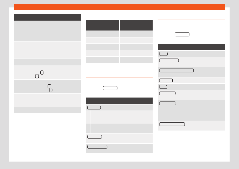
Infotainment System
Function button: function
The image viewed was obtained via
GPS localisation and upon pressing
this function button, the navigator
menu opens to start a r
oute to this
destination.
/
Rotate the image view 90° left or
right, or by swiping your fingers
across the screen in a circular direc-
tion.
R
eset the view of the image.
To stop the playback of a slideshow.
The
function button changes to
.
To continue the playback of a slide-
show. The function button
changes to .
/
Change image PREVIOUS or NEXT,
or by sliding your finger horizontally
across the screen.
SETTINGS Open the Image settings menu.
Enlarging or reducing the view
●
Slide 2 fingers across the screen, moving
them further apart or cl
oser t
ogether
.
●
OR:
t
urn the settings butt
on.
R
equirements for viewing images
Image files Maximum resolu-
tion
BMP 4MP
JPEG 4MP (Progressive Mode)
JPG 64MP
GIF 4MP
PNG 4MP
Image settings
Open the Image settings menu
●
Press the SETTINGS function button in the
main Images menu.
Function button: function
Image view : To adjust the image view format.
Automatic: Images scale to the size of the
screen (the image may not be displayed com-
pletely).
Complete: The images are displayed fully on
the screen.
Display time : To adjust the display time of images
during a slideshow.
Repeat slideshow : The active slideshow is repeated
infinitely.
Media settings
●
Select the MEDIA main menu by pressing
the infotainment key .
●
Pr
ess the SETTINGS
function button to open
the Media settings menu.
Function button: function
Sound : Sound settings
›››
page 176.
Manage Jukebox
a)
: To import files to the jukebox or to
del
ete existing files
›››
page 209.
Mix/repeat including subfolders
: Subfolders are inclu-
ded in the selected playback mode
›››
page 198
.
Bluetooth®
: Bluetooth
®
settings
›››
page 242
WLAN
a)
: WLAN settings
›››
page 211.
Video settings
: Settings for playing DVD videos or
fil
es.
R
emo
v
e saf
ely
: To prepare external data media for ex-
traction or disconnection. See also
›››
page 207, In-
serting or e
jecting a memory card and
›››
page 207, External data storage device con-
nected to the USB port .
Traffic programme (TP)
: The TP function (tracking of
traffic information stations) is active
›››
page 195.
a)
Only available for the model: Navi System Plus.
214
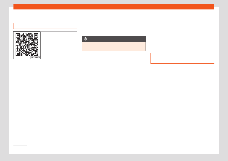
Operating modes
Navigation
1)
Intr
oduction
Fig. 201 Related video
General information
A GPS (Gl
obal P
ositioning Syst
em) sat
ellit
e
syst
em l
ocates the current position of the ve-
hicle. The vehicle’s sensors measure the dis-
tance travelled. The measurements are com-
pared with the stored detailed map resour-
ces, according to road indications stored in
them. Traffic reports, if any, will also be taken
into account in the route calculation (dynam-
ic route guidance
›››
page 223). Using all the
data available, the Infotainment system cal-
culates the optimum route to the destination.
The destination is defined by entering an ad-
dress or a point of interest, e.g. a petrol sta-
tion or hotel.
Navigation announcements and graphic rep-
resentations will guide you to your destina-
tion.
Depending on the country, some functions of
the infotainment system will not be available
on the screen when travelling higher than a
certain speed. It is not a malfunction, but is
due to compliance with legislation.
CAUTION
The navigation announcements may be in-
accurate (e.g. due to out-of-dat
e data).
Instructions for navigation
When the Infotainment system is unable to re-
ceiv
e any dat
a fr
om GPS sat
ellit
es (t
unnel
s,
garages), navigation can still continue using
the vehicle sensors.
Possible limitations in navigation
In areas that are not or are only partially digi-
tised (e.g. insufficient definition of one-way
streets and road categories), the Infotain-
ment system will still attempt to provide route
guidance.
In the case of missing or incomplete naviga-
tion data, it may not be possible to determine
the exact position of the vehicle. This may
mean that navigation is not as precise as usu-
al.
Navigation area and update of navigation
data
Road layouts change continuously. There-
fore, if the navigation data are not updated,
then errors or inaccuracies may occur.
SEAT recommends updating navigation data
on a regular basis.
Updating and using navigation da-
ta from an SD card
3 Only available for the model: Navi System
The SD card is f
actory fitted in slot 2 for SD
cards.
Navigation data that is currently valid for this
unit in order to allow all functions to be used
in full.
Updating navigation data
The current navigation data can be downloa-
ded in the internet at www.seat.com and stor-
ed in a SD card compatible with the unit.
Suitable SD Cards can be acquired at SEAT
dealerships.
The procedure is described on the internet at
www.seat.com.
»
1)
Valid for: Navi System and Navi System Plus.
215
Infotainment System
Using navigation data
●
Insert the memory card
›
›
›
page 207
.
●
W
ait f
or the t
esting icon to disappear.
If the inserted memory card contains naviga-
tion data, the following message appears:
“The source contains a valid naviga-
tion database”. Navigation can be started.
Note
●
The inserted memory card must be pre-
pared befor
e it is ejected
›››
page 207.
●
Navigation is not possible without the SD
card.
●
Do not remove the memory card while
the navigation data is in use. This could
damage the memory card!
●
The navigation memory card cannot be
used as a memory for other files.
●
SEAT recommends using only the original
SEAT cards. The use of other memory cards
could limit its operation.
Updating and installing navigation
dat
a
3 Only available for the model: Navi System Plus
The Infotainment system is equipped with an
internal navigation data memory. The r
e-
quired navigation data are already installed
on the system.
The Infotainment system always requires the
navigation data that is currently valid for this
unit in order to allow all functions to be used
in full. Using an old version may lead to errors
during navigation.
Updating navigation data
To update navigation data visit our website:
www.seat.com.
The navigation data must be installed after
downloading. Navigation is not possible from
the memory card.
Installing navigation data
The installation process takes about 2 hours.
If the Infotainment system is switched off, the
installation process is paused and will auto-
matically resume when switched back on.
●
Switch the ignition on.
●
Insert the memory card containing the nav-
igation data
›››
page 207
.
●
Press the infotainment key > Settings
> System information.
●
Press UPDATE to import the stored naviga-
tion data.
●
Follow the instructions displayed on the
screen.
Once installed, the memory card can be re-
moved. The memory card must be prepared
for removal
›››
page 207.
CAUTION
Do not remove the memory card while the
navigation data is being installed. The
memory card may be irreparably dam-
aged!
Note
●
The navigation memory card may not be
used as memory storage for other files. The
Infot
ainment system will not recognise the
files saved on it.
●
SEAT recommends a CLASS 10
1)
memory
card for the use of navigation data. The use
of other memory cards could limit its oper-
ation.
1)
The speed class of an SD card.
216
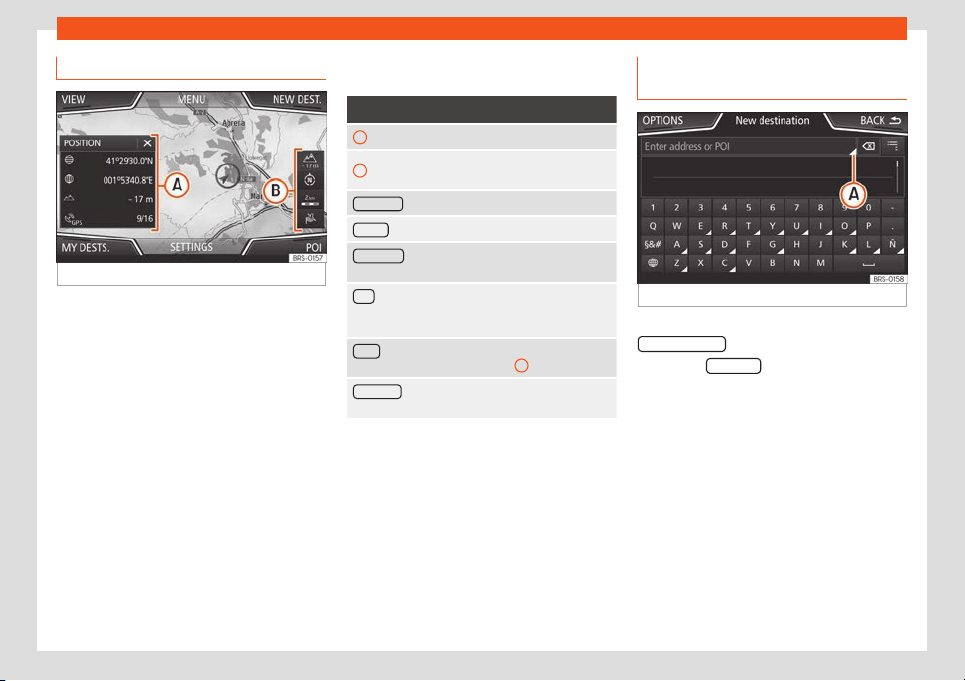
Operating modes
Navigation main menu
Fig. 202
Navigation main menu
Navigation functions can only be used if the
navigation dat
a f
or the ar
ea wher
e the v
ehi-
cl
e is driving is av
ailable in the infotainment
system.
The Navigation main menu allows you to se-
lect a new destination, call up a previously
used or stored destination and search for
points of interest.
Opening the main Navigation menu
●
Press the Infotainment button to open the
last menu that was open in navigation.
●
If the Navigation main menu is not dis-
played, press the infotainment button
again until the main navigation menu is dis-
played.
●
OR: Press the function button to return
menu by menu to the Navigation menu.
Navigation main menu function buttons
and indicators
Function button: function
A
The split screen is displayed
›››
page 221.
B
Messages and function buttons on the map
display
›››
page 222.
NEW DEST : To enter a new destination
›››
page 217.
ROUTE : During route guidance
›››
page 219.
MY DEST
S.
: To activate or manage stored destina-
tions
›››
page 219.
POI : Search for points of interest (car parks, fuel sta-
tions and restaurants) within a particular search area
›
››
page 221.
VIEW
: To modify or activate or deactivate the split
screen and show POI
›››
Fig. 202
A
›››
page 221.
SETTINGS : Open the Navigation Settings
menu.
New destination (entering the des-
tination)
Fig. 203
Search screen.
●
In the Navigation main menu, pr
ess the
Ne
w destination function button.
●
Press the OP
TIONS
function button and se-
l
ect the desir
ed destination entry t
ype
(
Search,
Address,
POI or
On the map).
●
Using voice control*, if you say Town, street
and number, without pauses, and then the in-
struction “Start Route Guidance” a route to
the given destination will start.
Search
Search for addresses and Points of Interest
using the keypad to enter them
›››
Fig. 203.
For cities, post codes and points of interest,
the full details must be entered. You can also
»
217
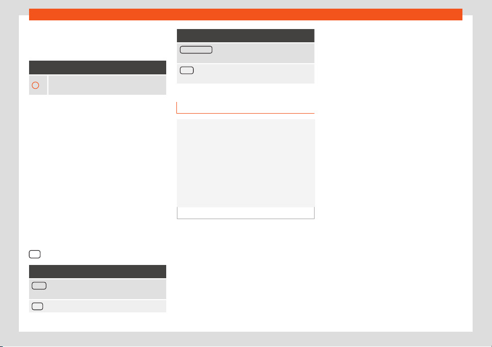
Infotainment System
search for points of interest by names or cat-
egories. When necessary, ent
er the name of
the cit
y t
o r
efine the sear
ch.
›››
Fig. 203
A
Press to open the cursor buttons (, ),
which allow you to move within the te
xt.
Steering
When narrowing down the destination ad-
dress, please not
e that every entry restricts
the available range of subsequent selections.
To enter an address press the function but-
tons in the following order:
●
Country, City (or postcode), Centre
(starts the r
oute to the centre of the indicated
city), Street, Number, Junction, LAST DES-
TINATIONS, START (starts route guidance to
the selected destination).
On the map
●
Select the destination on the map or enter
it using GPS coordinates and confirm with
OK
.
Function button: function
Store : Store the point of interest in the destination
memory
›››
page 219.
Edit : Edit the destination or enter another one.
Function button: function
Route options : Setting route options, see Naviga-
tion Settings > Route options.
Start : Starts guided navigation to the selected point
of interest.
After starting route guidance
Fig. 204
Route calculation.
When starting route guidance, the route is
cal
cul
at
ed based on the dat
a that hav
e been
sel
ect
ed in the Route options menu.
Three alternative routes are proposed
›››
Fig. 204. These 3 routes correspond to the
selectable route options: Economical, Fast
and Short.
Blue route: Economic route.
Red route: Fastest route.
–
–
Orange route: Shortest route to the
destination, even if it results in longer
travelling time.
●
Select the desired route by pressing it.
The route criteria settings in the Route op-
tions menu are modified accordingly.
If a route is not selected, the route guidance
starts automatically after approx. one minute
according to the setting selected in Route
options.
Once the route has been calculated, the sys-
tem gives the first navigation announcement.
Up to 3 navigation announcements are given
before a turn.
●
Press the adjustment knob to listen to the
last audible navigation instruction.
The indicated distances depend to a great
extent on the type of road and the traffic
speed. On motorways, for example, naviga-
tion announcements are received much earli-
er than in urban traffic.
The corresponding navigation announce-
ments are also given on roads with several
lanes that split, and on roundabouts, for ex-
ample: “Leave the roundabout at the second
exit.”
A navigation announcement informs you
when you have reached your “destination”.
–
218
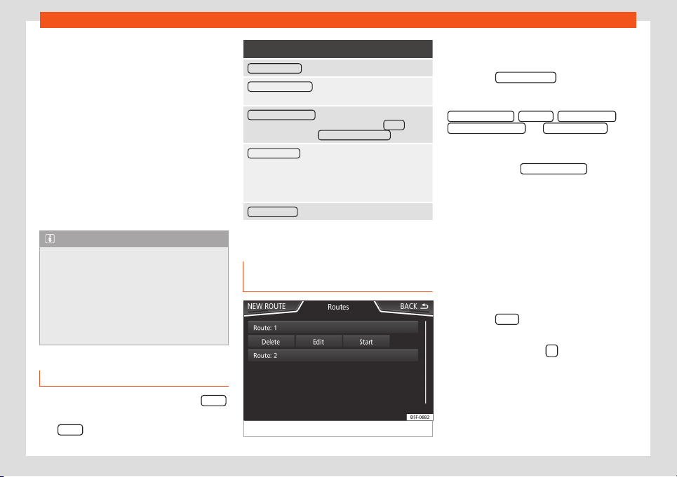
Operating modes
A navigation announcement informing you
that you hav
e r
eached the “destination ar
ea”
is giv
en if the e
x
act destination cannot be
r
eached.
During dynamic route guidance, you re-
ceive information about reported traffic con-
gestion on the route. An additional navigation
announcement is given if the route is recalcu-
lated.
During a navigation announcement, you can
change its volume using the button .
For other announcement settings, select
Navigation > Settings > Navigation
announcements.
Note
●
If you miss a turning during route guid-
ance and are currently unable t
o turn back,
keep on driving until the navigation system
offers a new route.
●
The quality of the announcements and
recommendations depends on the naviga-
tion data available and any reported traffic
problems.
Route
In the Navigation main menu, pr
ess the R
out
e
function button.
The R
out
e function button is only displayed
with r
out
e guidance activ
at
ed.
Function button: function
STOP GUIDANCE : Aborts current route guidance.
ENTER DESTINATION : To enter a new destination or a
new stopover
›››
page 217.
CONGESTION AHEAD : To exclude a section of the
route. To cancel the exclusion, pr
ess the Route
func-
tion button and then CANCEL CONGESTION .
CHANGE ROUTE
a)
: The map of the calculated route
appears and by holding a finger on the r
oute and
dragging the finger across said map, the route is
changed to the road(s) that you want and the new
route is then recalculated.
ROUTE DETAILS
: View route information.
a)
Only available for the model: Navi System Plus
My destinations (destination mem-
ory)
Fig. 205 List of saved routes.
The stored destinations can be selected from
the My destinations menu.
●
Press the My destinations
function button in
the main Navigation menu.
●
Select the desired function button.
S
T
ORE POSITION , ROUTES , DES
TINATIONS
,
LAS
T DES
TINATIONS OR HOME ADDRESS .
St
or
e position
●
By pr
essing the S
T
ORE POSITION
function
butt
on, the curr
ent position is st
or
ed as a
Flagged destination in the Destination
memory.
T
o sav
e the st
ored position permanently as a
flagged destination, change the name of
the position in the destination memory. Oth-
erwise, the saved position is overwritten when
another flagged destination is saved.
●
Mark the Flagged destination in the
destination memory.
●
Press the Store
function button.
The name can be changed in the f
oll
o
wing
input windo
w
. Pr
ess the
function button to
st
or
e the destination.
R
out
es
In the
Route mode
, you can define v
arious
destinations (final destination and stopovers).
»
219
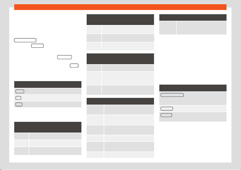
Infotainment System
The st
arting point of a route is always the
v
ehicl
e
’
s curr
ent position. The
destination is
the end point of a route. Stopover destina-
tions are driven to before the destination.
●
In the Navigation main menu, press the
My Destinations
function button.
●
Press the ROUTES function button.
If you hav
e not st
or
ed any r
out
es or w
ant t
o
create a new route, press the New route
func-
tion butt
on and then f
oll
o
w the instructions as
f
or a ne
w destination, bef
ore pressing Store
.
Pr
essing on a st
or
ed r
out
e brings up the f
ol
-
lowing function buttons:
Function button: function
Delete : To delete a stored route.
Edit : To edit and store a route.
Start : To start route guidance.
Function buttons and indications in the New
route or Edit menu
Function button or message: function or
meaning
Stopover.
Destination.
...
Estimated time of arrival.
Function button or message: function or
meaning
...
Calculated distance to destination.
...
Estimated travelling time.
...
Distance to the next stopover.
Press on the destination to display the
function buttons
Delete destination.
Starting route guidance dir
ect to the se-
l
ected destination. The stages are omit-
ted.
Opening the det
ailed view of the desti-
nation in question.
Available function buttons
New desti-
nation
Add a new destination.
Destina-
tions
Adding a new destination from My
destinations.
Storing To store the created route in the route
memory.
Start Start route guidance.
Calculate To update the calculated distance and
estimated arrival time.
a)
Stop To stop activ
e route guidance.
b)
Available function buttons
Moving a stopover or a destination to
another position on the list. Press and
drag to move the destination.
a)
Only displayed with route guidance activated and
when a destination has been added to the tour.
b)
Only displayed with route guidance activ
ated.
Last destinations
List of last destinations.
My destinations
●
Press the Options function button and se-
lect the desired function button.
Function button: function
Destination memory : View of destinations stored man-
ually and from imported vCards
›››
page 22
4, Im-
porting vCards (electronic business cards).
Favourites
: List of destinations stored as favourites.
Contacts : List of phone book contacts that have a
stored address (postal address).
Home address
Only one addr
ess or position can be st
or
ed
as the home addr
ess at any one time
.
Pr
essing will st
art guidance to the stored
home address.
220
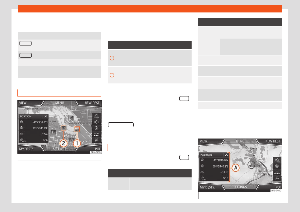
Operating modes
If a home addr
ess
has not yet been st
or
ed,
an addr
ess can be assigned.
Assigning the home address for the first time:
Position : Press to store the vehicle's current position
as the home address.
Address : Press to enter the home address manually.
Editing the home address:
The home address can be edited in the Naviga-
tion settings > Manage memory menu.
Special destinations (POI)
Fig. 206
Points of interest on the map.
The points of interest saved in the memory
ar
e divided int
o diff
er
ent cat
egories. Each
cat
egory of special destinations has a sym-
bol assigned t
o it.
In the Map settings menu, you can indicate
the special destinations that you want to dis-
play on the map. Up to 10 categories can be
selected.
Selecting a point of interest on the map
Function button: function
1
There are several points of interest in the area.
Press this symbol to open a list of points of in-
terest.
2
The only point of interest in this zone. Press the
symbol to open the detailed view of the point of
interest.
Quick POI search
In the Navigation main menu, pr
ess the POIs
function button and the three main catego-
ries will appear
. Alt
ernativ
ely, ent
er the name
of the point of int
er
est t
o be searched using
the new destination keypad, or press
Search nearby
on the map
›
›
›
t
abl
e on
page 222
.
Vie
w
In the Navigation main menu, pr
ess the Vie
w
function button.
Function button: function
Map display in two dimensions (con-
ventional).
Function button: function
Map display in three dimensions (bird's
eye vie
w).
The places of interest and well-kno
wn
buildings are also shown in detail and
in colour
.
a)
To display the destination on the map.
a)
To display the route on the map.
Auto /
Day / Night
To switch between day and night for-
mat.
SPLIT
SCREEN
Show the split screen
›
››
page 221.
POI Sho
w special destinations.
a)
Only displayed with route guidance activated.
Split screen
Fig. 207
Split screen displayed.
»
221
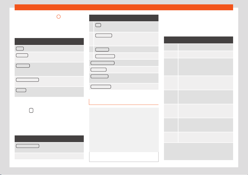
Infotainment System
The split screen
›
›
›
Fig. 207
A
shows the in-
f
ormation det
ail
ed bel
o
w
:
●
Pr
essing the name displays a menu with the
following options:
Function button: function
Audio : Current audio source.
Compass : Displays a compass with the current di-
rection and position of the vehicle (street name).
Manoeuvre : Displays a list of the next manoeuvres,
POIs or TMCs on the route and pressing them brings
up additional information
FREQUENT ROUTES
a)
: Information on the user's most
frequent routes.
Position : current vehicle position in coordinates and
GPS status (satellite reception).
a)
Only shown when route guidance is not active or
when pr
edictiv
e r
out
e guidance is activ
e
.
Pr
ess the
function button to close the split
scr
een.
At any moment during navigation, pr
essing
inside the map will mak
e a pop-up menu ap-
pear with the f
oll
o
wing functions:
Function button: function
Clicking on the map : Shows the details of the selected
point, street name or coordinates
Only when you press on an icon on the map:
Function button: function
POI : name of the point of interest (when only one
appears on the map).
Group of POIs : more points of interest (when you
press on the map on various POIs grouped to-
gether).
FAVOURITE : name of the favourite.
HOME ADDRESS : Home address.
Start route guidance : starts guidance directly.
Add stopover
: only when you have an active route.
Search nearby : enters in the search menu, but only
for the area around the point selected on the map.
Demo mode st
art
(only when demo mode is active)
Map display
Fig. 208
Messages and function buttons on
the map displ
ay.
Function buttons and messages on the
map displ
ay.
T
o activ
at
e function butt
ons
and , press
function button .
Function button: function
Current altitude indicator.
To centre the vehicle position on the map.
To centre the destination on the map. On-
ly displ
ayed if either Display destination
on map or Display r
oute on the map is se-
lected
›››
page 221.
To change the orientation of the map
(north-facing or direction of travel). Only
availabl
e in 2D mode.
Map scale. To change the scale, turn the
adjustment knob or move two fingers to-
gether or apart on the screen.
Selecting aut
omatic scaling. If the func-
tion is active, the symbol is displayed in
blue.
Briefly increases the scale of the map
(zoom) The selected scale is displayed
again after a few seconds.
Mute or repeat the last announcement,
change the announcement volume.
Road signs: Depending on the vehicle's equip-
ment, the road signs stored in the navigation data are
displayed. Select Navigation > Settings >
Map > Show road signs.
222

Operating modes
Traffic bulletins and dynamic desti-
nation guidance (TRAFFIC)
Fig. 209
Traffic reports
The Infotainment system constantly receives
tr
affic r
eports (T
MC/T
MCpr
o) in the
back
-
ground, if a traffic information station is
tuned.
Traffic bulletins are displayed on the map
with symbols
›››
page 223, Traffic reports on
map (selection) and they are required dy-
namic destination guidance
›››
page 223,
Dynamic route guidance.
List of available traffic reports
●
Press the Infotainment button and then
select the Traffic context.
Dynamic route guidance
In order for dynamic route guidance to func-
tion, Dynamic route must be activated in the
route options.
If a traffic report is received that affects the
route being travelled, an alternative route will
be searched for if the system calculates that
time can be saved.
If, on the other hand, the alternative route
does not save time, the route will continue
with the traffic jam. In both cases, an an-
nouncement will be made.
Shortly before reaching the announced traf-
fic jam, it is indicated again.
Avoiding a traffic jam by following the instruc-
tions of a traffic bulletin does not always save
time, for example, if alternative routes are
congested. The effectiveness of dynamic
navigation depends on the traffic bulletins
that are received.
The rest of the route that has to be travelled
can be manually excluded to force its recal-
culation
›››
page 219.
Traffic reports on map (selection)
Symbol: Meaning
: Slow traffic
: Traffic jam
Symbol: Meaning
: Accident
: Slippery road surface (ice or snow)
: Slippery road surface
: Danger
: Road w
orks
: Strong wind
: Road cl
osed to traffic
During route guidance, traffic incidents that
do not aff
ect the cal
cul
at
ed r
out
e cal
culated
are displayed in grey.
The length of a traffic jam on the calculated
route is shown by a red line.
Incidents that affect the calculated route and
that have led to the recalculation of the route
are shown in orange.
The position of a symbol indicates the start of
the traffic jam if it is precisely specified in the
traffic bulletin.
223
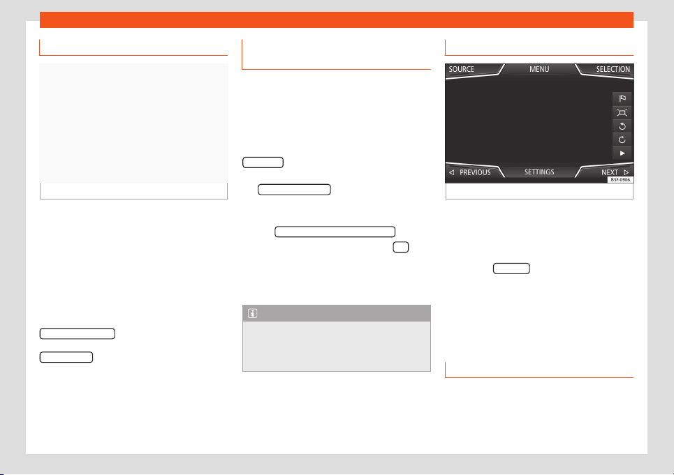
Infotainment System
Predictive navigation
Fig. 210
Predictive navigation
When you activate Predictive navigation, the
syst
em det
ects and st
or
es in the back
gr
ound
r
outes that are frequently followed, without
them being active destination routes.
This function has no navigation announce-
ments unless the user requires them, getting
them by pressing the settings button.
●
On the main screen of the Navigation menu,
in the pop-up window, press the
FREQUENT ROUTES
button. To display fre-
quently f
oll
o
w
ed r
out
es pr
ess the
Show on map
button
›
›
›
Fig. 2
10
.
Impor
ting vCar
ds (electronic busi-
ness cards)
Importing vCards to the destination mem-
ory
●
Insert the data storage device with the stor-
ed vCards or connect it to the Infotainment
system
››
›
page 198.
●
In the Navigation main menu, press the
SETTINGS
function button.
●
In the Navigation settings menu, press
the Import destinations
function button.
●
Select the data carrier with the vCards
sav
ed in the list.
●
Pr
ess Import all vCar
ds fr
om this f
ol
der .
●
Confirm the import notice with the OK
function button.
Sav
ed vCar
ds will no
w be in the destinations
memory
›
›
›
page 2
19.
Note
Only one address per vCard can be impor-
ted. In the event any vCards have multiple
addr
esses, only the main address will be
imported.
Navigation with images
Fig. 211
Images main menu.
Selecting an image and starting route
guidance
●
Press the Infotainment butt
on and then
sel
ect the
Images cont
e
xt.
●
Pr
ess the SOURCE
›
›
›
Fig. 2
11 function but-
t
on and sel
ect the dat
a storage device where
the images are stored.
●
If the image displayed was taken using GPS
localisation, the function button will appear.
Press to start guidance to a destination.
Road signs indication
The road sign indication must be active in the
Navigation settings menu
›
›
›
page 225
.
If ther
e ar
e r
oad signs stored in the navigation
data for the route you are driving on, the
224
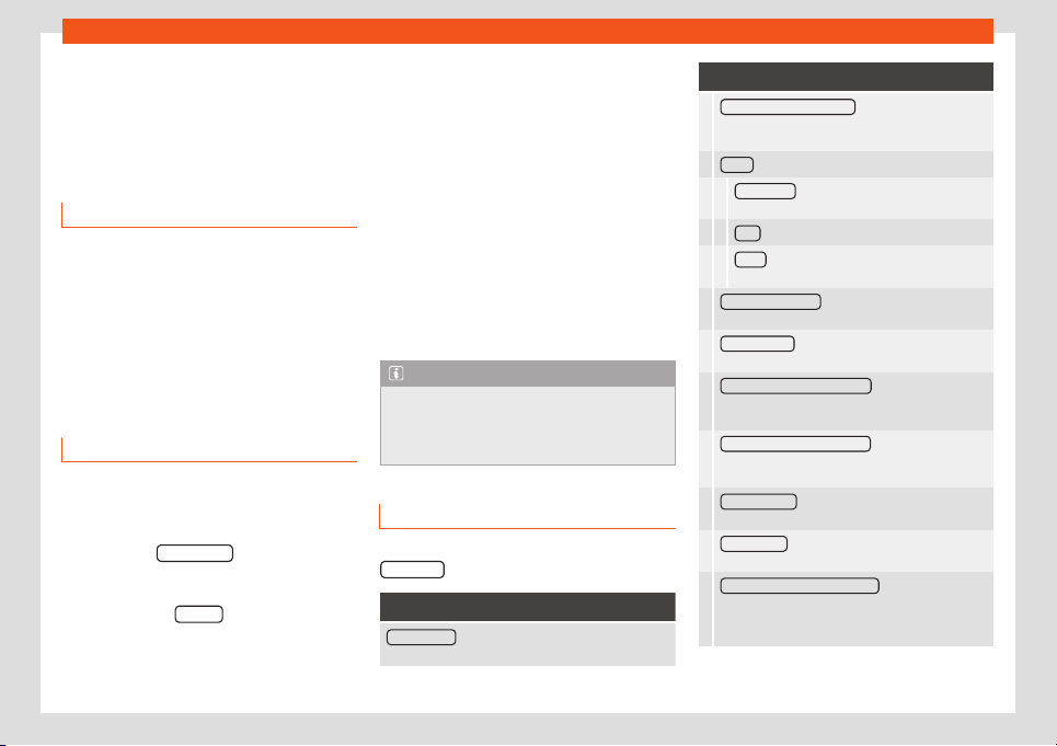
Operating modes
system can display them on the map (e.g. a
speed limit).
T
ak
e int
o account the age of the navigation
dat
a and the limit
ations of the navigation sys-
t
em
›
››
page 215!
Recognition of road signs
Some vehicles have a road sign recognition
camera. If the vehicle has road sign recogni-
tion and it is active
, road signs detected by
the system will be displayed on the map,
along with additional information.
Read and take into account the information
and indications of the road signs recognition
system
›››
page 72.
Route guidance in Demo mode
If demo mode is activated in the Navigation
settings menu, an additional pop-up win-
do
w opens when you st
art r
out
e guidance
.
●
Pr
essing the Demo mode
function button
st
arts a “virt
ual r
out
e guidance” t
o the desti-
nation you hav
e ent
ered.
●
If you press the Normal
function button, a
“r
eal r
out
e guidance” st
arts.
The de
v
el
opment and operation of virtual
route guidance is compatible with the devel-
opment and operation of real route guidance.
Virtual route guidance is repeated after
reaching the fictitious destination and re-
starts from the starting point, if it is not inter-
rupted beforehand.
When the starting point of the Demo mode is
manually set Navigation settings menu,
the virtual route guidance starts from that po-
sition.
A manually entered starting point is overwrit-
ten with the current location of the vehicle, if
the vehicle starts moving.
Note
Deactivate the Demo mode after use, oth-
erwise you will always have to select
whether to st
art a virtual route or normal
route before starting route guidance.
Navigation settings
●
In the Navigation main menu, pr
ess the
SETTINGS
function button.
Function button: function
Route options : To make the route calculation adjust-
ments.
Function button: function
Suggest 3 alternative routes : After starting route
guidance, 3 alternative routes are pr
oposed
›››
page 218.
Route
: Route type selection.
Economical : Route calculation, taking econom-
ic aspects into account.
Fast : The fastest route to the destination.
Short : The shortest route to the destination,
even if it results in longer travelling time
.
Most frequent routes
: Information on the user's most
frequent routes.
Dynamic route : Dynamic route guidance activates
when a TMC is received
›››
page 223
.
Avoid motorways and highways
: Motorways will be
excluded from the route calcul
ation wherever
possible.
Avoid ferries and motorail trains
: Ferries and motorail
trains will not be taken into account for the rout
e
calculation, wherever possible.
Avoid toll roads
: Toll roads will be excluded from
the route calculation, whenever possibl
e.
Avoid tunnels
: Tunnels will be excluded from the
route calculation, whenever possibl
e.
Avoid routes requiring toll stickers
: Mandatory toll
stickers (stickers certifying that the toll has been
paid) will be excluded from the r
oute calculation
whenever possible.
»
225
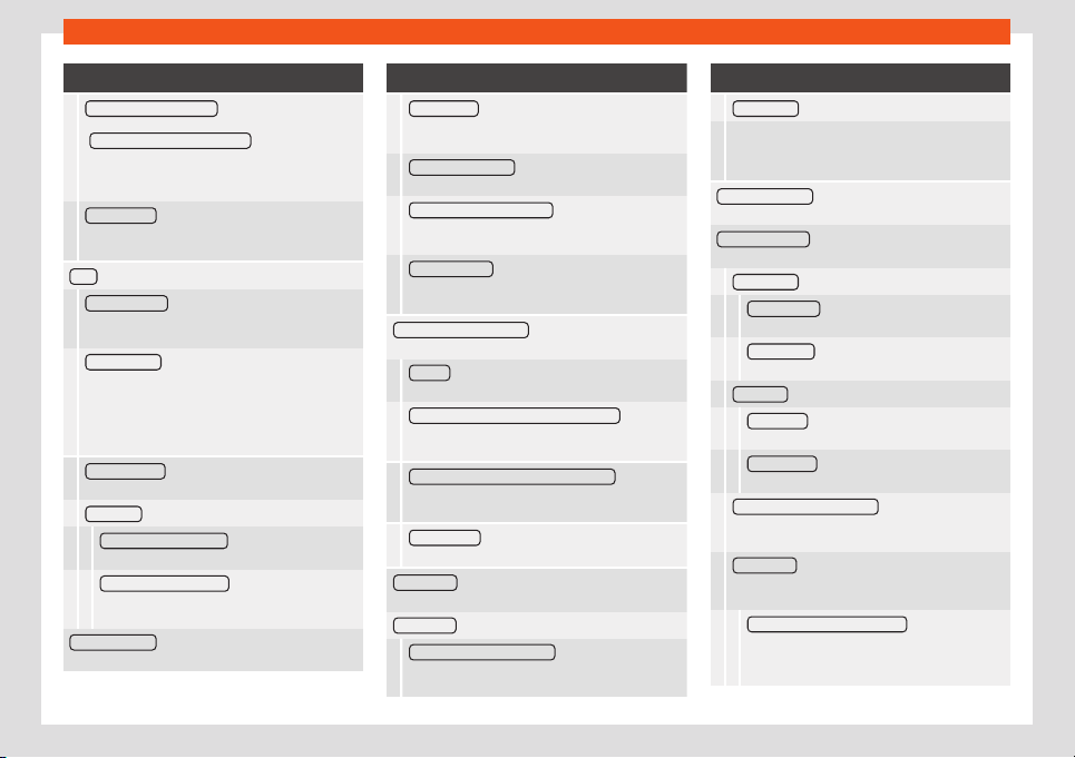
Infotainment System
Function button: function
Show available toll stickers
a)
: To mark the available
toll stickers on the list
( Av
oid routes requiring toll stickers
must be active).
Routes requiring toll stickers will be taken into ac-
count in the route calculation if it is marked that
the toll sticker is available.
Include trailer : Calculate the route and arrival
time, depending on whether a trailer is being tow-
ed.
Map : To adjust the map display settings.
Show road signs : The road signs stored in the navi-
gation data for the road you are driving on are dis-
played during r
oute guidance
›››
page 224.
Lane guidance
: During route guidance, an addi-
tional indication is displayed to recommend a
lane when driving, and when turning on roads with
se
veral lanes. Only if the data bank contains infor-
mation about the area that is being driven
through.
Show favourites
: The destinations saved as favour-
ites on the map are displayed ().
Show POIs
Select categories for POIs : To select the POI cate-
gories shown on the map
›››
page 221.
Show brand logos for POIs
: Displays logos of the
selected special destinations categories (e.g.
displays logos of service st
ations).
Manage memory
: To make adjustments to the stored
destinations.
Function button: function
Sort contacts : To select the sequential order of
agenda entries recorded with postal addresses,
see also
››
›
page 219.
Define home address
: To assign or edit a home ad-
dress, see also
›››
page 220.
Import destinations (SD/USB) : To import digital busi-
ness cards (vCards) into the destination memory
›››
page 22
4.
Delete user data
: To delete stored destinations (e.g.
Last destinations or the Destination
memory).
Navigation announcements : To change the navigation
announcements settings.
Volume : To adjust the volume of audible driving
recommendations.
Entertainment fading (nav. announcements) : Set the
volume of the active audio source during naviga-
tion announcements.
No navigation announcements during calls : During a
telephone conversation, audio driving recommen-
dations will not be given.
Note: My POIs : Audible warning when approaching
a special destination.
Speed limits : Shows the speed limits, depending on
the road, of the country that is being driven through.
Fuel options : To change fuel related settings.
Select preferred petrol station : The brand of the se-
lected service station is given priority in special
destination search r
esults.
Function button: function
Fuel warning : The fuel warning is active.
If the fuel level reaches the reserve, an appropri-
ate warning is generated that enables the service
station search.
Version information : Information about stored naviga-
tion data.
Advanced settings : For making advanced changes to
the navigation settings.
Time display : Indication during route guidance.
Time of arrival
: The estimated time of arrival at
the destination is displayed.
Running time : The envisaged travelling time to
the destination is displayed.
Status line : View during route guidance.
Destination : The calculated distance to the
destination is shown.
Next stopover : The calculated distance to the
next stopover is shown.
Note: National bor
der crossed
: Indication of the
speed limits of the country in question when
crossing a border.
Demo mode : When the Demo mode is active and
route guidance is started, a virtual guide to the en-
t
ered destination may be started
›››
page 225.
Define demo mode starting point
: If the Demo
mode is active and the vehicle is stopped, a fic-
titious starting point can be set for the virt
ual
route guidance.
226
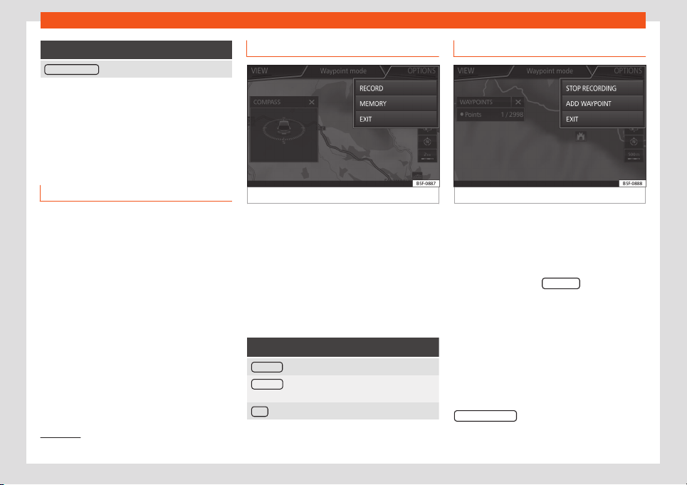
Operating modes
Function button: function
Waypoints mode
b)
: To start Offroad navigation.
a)
This functionality will depend on the country.
b)
Only available on model: Navi System Plus.
Navigation in Offroad
mode*
1)
Introduction
Offroad* navigation is a function for offroad
driving that pr
o
vides dir
ections in “
non-digi-
tised ar
eas
” at l
ow speeds.
Non-digitised areas are areas about which
the system does not have information for the
streets or terrain. It does not detect streets,
buildings or natural limits such as mountains
or rivers, although they may be shown on the
map.
Offroad* navigation is not suitable for driving
on conventional roads as it does not detect
one-way streets, motorway entries or similar.
Offroad Navigation Menu
Fig. 212
Offroad Navigation Menu start
Press the SETTINGS function butt
on in the
main Navigation menu.
●
In the menu, pr
ess the
W
aypoint mode
function butt
on.
●
The Offr
oad Navigation menu opens
›
››
Fig. 212.
Function buttons in the Offroad Navigation
menu
Function button: function
RECORD : Initiates the plotting of an Offroad tour.
MEMORY : Opens a list allowing the selection of a
stored Offroad tour.
EXIT : Ends Offroad navigation.
Recording an Offroad tour
Fig. 213
Recording an Offroad tour
An Offroad tour is formed by a series of stor-
ed w
aypoints
.
St
ar
ting r
ecor
ding
●
In the Offr
oad Navigation menu, in the pop-
up window press the RECORD
pop-up button.
●
In the pop-up window, the user is able to
pl
ot the t
our with a giv
en destination or st
art
pl
otting the r
out
e without giving a final desti-
nation.
●
Starts plotting the route.
The offroad markers can be recorded by in-
dicating a manual waypoint.
●
In the Offroad Navigation menu, press the
ADD WAYPOINT
function button. The tour
»
1)
Only available for the model: Navi System Plus
227
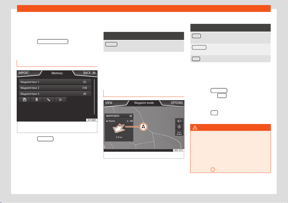
Infotainment System
waypoints defined manually are shown on
the map by a mark
er
.
Ending r
ecor
ding
●
Pr
ess the S
T
OP RECORDING
function button
in the main Offr
oad Navigation menu.
Managing st
or
ed Offr
oad t
ours
Fig. 214
Offroad Navigation menu, stored
t
ours
●
Press the MEMORY function button in the
Offr
oad Navigation menu.
●
A list of st
or
ed Offr
oad t
ours opens, if ther
e
ar
e any.
When a tour is selected, the following icons
will appear
›››
Fig. 214:
Export the tour to an SD card.
Edit the name of the tour.
Delete the tour.
Load tour
Function button: function
IMPORT : allows the import of an Offroad route in
“.GPX” format.
Loading an Offroad tour
When the Offroad tour is selected, press Play
and the selected tour will be loaded onto
the Navigation system.
Creating an Offroad tour
Fig. 215 Offroad route guidance mode
Start route guidance
●
Loads the stored Offroad tour.
●
Starting off in a stored route is not detected
by the syst
em aut
omatically.
Set
up
Function button: function
Invert : Reverses the direction of the stored Offroad
tour.
Next point : Starts the Offroad tour from the nearest
point.
Start : Starts the complete Offroad tour.
When route guidance starts, the system
switches to the map view.
Stopping r
oute guidance
●
Press the OPTIONS
button on the screen
and then pr
ess St
op
.
End w
aypoint navigation
●
Pr
ess the Exit function button in the Off-
r
oad Navigation menu
WARNING
Terrain features are disregarded during
route guidance Drive slowly and foll
owing
the instructions in order to perform the ma-
noeuvre as far as possible!
●
The general direction of travel is indica-
ted straight ahead by direction arrows in
the Infotainment System pop-up window
›››
Fig. 215
A
.
228
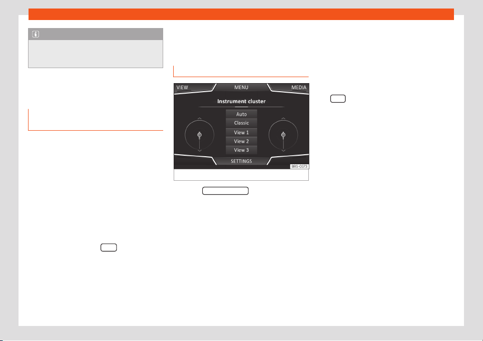
Operating modes
Note
If an Offroad tour is being recorded, this is
automatically stored if Offroad navigation
is discontinued.
Vehicle Menu
Introduction to using the Vehicle
menu
Pressing button of the inf
ot
ainment syst
em
accesses its main menu with the f
oll
o
wing
options:
●
VIEW
●
RADIO or MEDIA (t
o control playback in ra-
dio or media mode)
●
HDC (shown if the descent assistant* is ac-
tive
›››
page 261)
●
PREVIOUS-NEXT (to change screen)
●
SETTINGS
›››
page 82
With the function button VIEW
you can ac-
cess the f
oll
o
wing inf
ormation:
●
INS
TRUMENT P
ANEL
›
››
page 229
●
SPORT*
›››
page 230
●
OFFROAD*
›››
page 230
●
CONSUMERS
›››
page 231
●
DRIVING DATA
›››
page 231
●
ECOTRAINER
›››
page 231
●
VEHICLE STATUS
›››
page 232
Instrument panel
Fig. 216 Instrument panel
Press the Instrument panel button to choose
fr
om the v
arious displ
ay options and cust
om-
ise the inf
ormation that appears in the SEAT
Digit
al Cockpit
›
››
page 65.
Automatic View
Pre-set information depending on the Driving
mode.
Classic View
The needles are displayed at full length.
Views 1, 2, 3
Customise the information that appears in
the digital cockpit. The user chooses which to
display, and in what order, by moving a finger
vertically over the dials.
Depending on the version, the Views can be
memorised by existing the menu or keeping
the View
button pressed.
229
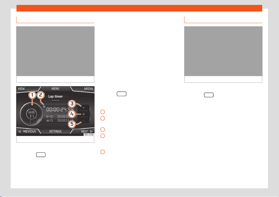
Infotainment System
Sport*
Fig. 217
SPORT menu
Fig. 218
SPORT Menu Lap timer
●
Press the infotainment button .
●
Press the VIEW function button and select
SPOR
T
.
If the corr
esponding equipment is av
ail
abl
e
,
the following information appears in the
Sport option
›››
Fig. 217:
Instantaneous power expressed in kW
G forces
Turbo pressure, expressed in bar (“bar”),
kilopascals (“kPa”) or in pounds per
square inch (“psi”). Press the Settings
button to change the units of pressure
›››
page 174
Coolant temperature
Oil temperature
Only 3 of these items of information can be
displayed at the same time, but the user
chooses which to display, and in what order,
by moving the finger vertically over the dials.
Press the NEXT
button to bring up the L
ap
timer
menu that is described bel
o
w
›
›
›
Fig. 218:
Analogue lap timer
New timing is started by pressing on the
surface of the digital lap timer +.
Stop lap timer/Lap time.
The analogue lap timer's time is stopped
for 5 seconds. After 5 seconds, the ana-
logue lap timer shows the real time again.
Statistics/delete last lap time.
1.
2.
3.
4.
5.
1
2
3
4
5
Offroad*
Fig. 219
Offroad CAR Menu.
●
Press the infotainment button .
●
Press the VIEW function button and select
OFFROAD.
If the corr
esponding equipment is av
ail
abl
e
,
the inf
ormation that appears is the f
ollowing:
Compass.
Turning angle of steered wheels.
Coolant temperature.
Lubricating oil temperature
Only 2 of these items of information can be
displayed at the same time, but the user
chooses which to display, and in what order,
by moving the finger vertically over the dials.
1.
2.
3.
4.
230
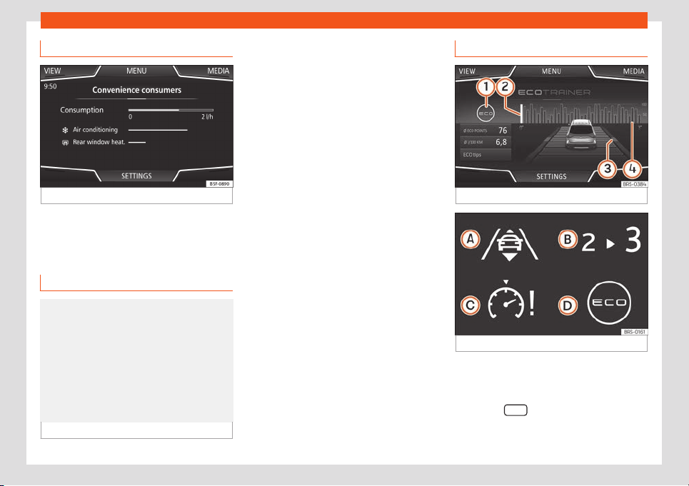
Operating modes
Consumers
Fig. 220
Convenience consumers.
Access information about the vehicle’s main
conv
enience consumers. It is sho
wn via a
consumption indicat
or bar in l/h (gal/h).
Driving dat
a
Fig. 221 Driving data.
The on-board computer has 3 memories.
They can be used t
o displ
ay: dist
ance
, time
,
av
er
age speed, average consumption and
range.
1. Since start
Indication and storage of distance travelled
and consumption values between the ignition
being turned on and it being turned off.
2. Since refuelling
Display and storage of the values for the jour-
ney and the consumption. By refuelling, the
memory will be erased automatically.
3. Long-term
The memory records the values for a specific
number of partial trips, up to a total of 19
hours and 59 minutes or 99 hours and 59 mi-
nutes, or 1999.9 km (mi) or 9999 km (mi), de-
pending on the model of instrument panel.
When one of these values is reached (de-
pending on the version of the instrument pan-
el), the memory is automatically deleted and
starts counting again from 0.
Ecotrainer
Fig. 222
CAR Ecotrainer menu.
Fig. 223
Driving style symbols.
Open the ECOTRAINER Menu
●
While the vehicle is stopped, press the Info-
t
ainment butt
on
.
●
Pr
ess the VIEW function button and select
ECOTRAINER.
»
231
Infotainment System
Provides information about your driving style.
The inf
ormation on driving st
yl
e is only e
v
alu-
at
ed and displ
ayed when moving forward.
∅ ECO points: indication on driving style
Indicates driving style efficiency since start
on a scale of 0 to 100. The higher the value
displayed, the more efficient the driving style.
Press on the display for more information.
Statistics are shown for the last 30 minutes of
driving from the start. If 30 minutes have not
elapsed, the values of the last trip are shown
in grey.
∅ l/100 km: Average fuel consumption
Shows the average fuel consumption. The
value is calculated using the kilometres trav-
elled since start as a reference. Press on the
display for more information. Statistics are
shown for the last 30 minutes of driving from
the start. If 30 minutes have not elapsed, the
values of the last trip are shown in grey.
Eco tips: Tips on how to save fuel
Press the ECO tips
button to get advice on
ho
w t
o sav
e fuel. These tips can only be con-
sult
ed whil
e the v
ehicl
e is stopped.
Efficient driving style assessment
The representation uses different elements to
show driving style efficiency.
Indication
›››
Fig. 222: Meaning
1
To the left of the columns are different symbols
that provide information about the current driv-
ing style
›
››
table on page 232.
2
The white column is an indication of where the
efficiency graph starts (from left to right).
It shows the position of the evaluation that is
currently being performed.
3
Bars to illustrate acceleration.
The position of the car represents acceleration.
If the speed is constant, the car remains in the
centr
al zone. If it accelerates or brakes, the car
moves backwards or forwards respectively.
4
Columns representing driving style efficiency.
Horizontally, the columns represent retrospec-
tiv
e driving efficiency, and move from left to
right approximately every 5 seconds. The high-
er the columns, the more efficient the driving
style.
The colour of the sky represents the average of
the last 3 minutes. The colour changes from
grey (less efficient) to blue (more efficient).
Symbols
›››
Fig. 223: Meaning
A
Thinking ahead. Sudden changes in accelera-
tion lower the efficiency of the driving style.
B
Gear recommendation.
C
Current speed has a negative impact on fuel
consumption.
D
Ecological driving style.
Vehicle status
Fig. 224
Standard representation: vehicle sta-
t
us.
Fig. 225 Standard representation: vehicle sta-
t
us.
Press the V
ehicl
e st
at
us button to access infor-
mation on the Vehicle status messages
and Start-Stop system.
232
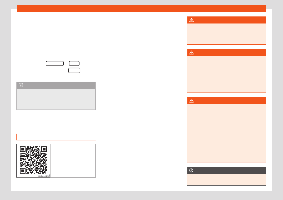
Operating modes
The Vehicle status messages ar
e dis-
pl
ayed
›
›
›
Fig. 22
4
, in addition to being
specified on the corresponding button.
According to the parties affected by these
messages, they will be shown in different col-
ours (depending on their importance) on the
vehicle's screen.
To access the Tyre Pressure Loss Indi-
cator, press the FORWARD
or BACK keys.
Fr
om this same menu, use the
SET button
t
o st
or
e the t
yr
e pr
essur
es.
Note
The values shown on the figures
›››
Fig. 220,
›››
Fig. 221,
›››
Fig. 224 and
›››
Fig. 225 are in-
dicative and may vary depending on the
equipment.
Telephone
Gener
al inf
ormation
Fig. 226 Related video
Telephone functions can only be used if there
is a mobil
e phone connect
ed by Bluet
ooth t
o
the inf
ot
ainment syst
em
›››
page 235.
To do this, the phone must have the Blue-
tooth
®
function activated.
The instructions shown on the screen for the
telephone menus will depend on the mobile
telephone used.
Only use compatible Bluetooth
®
devices. For
further information on compatible Bluetooth
®
products, ask your nearest SEAT dealer or
check on the internet.
Use the instruction manual of the mobile tele-
phone and of any accessories.
If you detect any operating issues between
your mobile telephone and the Infotainment
system, restart your mobile by switching it off
and on again.
Some functions and setup can only be per-
formed when the vehicle is stopped and are
not available on all mobile telephones.
You may experience poor reception or may
be cut off in areas where the signal is weak.
Most electronic devices are shielded against
HF (high-frequency) signals. In any case, the
electronic equipment may not be protected
from the HF signals of the telephone man-
agement system. This may cause interfer-
ence.
WARNING
General, mandatory, legal and country-
specific instructions and laws for the use of
mobile phones inside the vehicle must al-
w
ays be considered.
WARNING
Speaking by telephone and using the mo-
bile telephone management system whilst
driving can distract you fr
om the road and
cause an accident.
●
In areas of little coverage your call may
be cut off and you may not be able to make
even emergency calls.
WARNING
Mobile telephones may interfere with and
alter the correct operation of pacemakers
if they are carried directly o
ver them.
●
Maintain a minimum distance of at least
20 centimetres between the aerials of the
mobile telephone and the pacemaker.
●
Do not carry your switched-on mobile
telephone in your breast pocket directly
over the pacemaker.
●
If you suspect interference, switch off the
mobile telephone immediately.
CAUTION
High speeds, poor weather or road condi-
tions and the quality of reception can all
»
233
Infotainment System
affect the audio quality of a telephone con-
versation in the vehicle.
Note
●
R
estrictions on the use of devices using
Bluetooth
®
technology may apply in some
countries. For fur
ther information, contact
the local authorities.
●
If you wish to connect a device via Blue-
tooth
®
, consult the safety warnings in its in-
struction manual. Only use compatible
Bluetooth
®
devices.
●
Using a mobile telephone inside the vehi-
cle may provoke noise in the speakers.
●
Some networks may not recognise all of
the language characters or offer all of the
services.
Places with special regulations
In the majority of cases, these places are
signpost
ed, but not al
w
ays cl
early. They in-
clude
, f
or e
xample:
●
the vicinity of chemical pipelines and tanks
●
The lower decks of boats and ferries.
●
In the proximity of vehicles that run on liquid
gas (such as propane or butane).
●
places where the air is laden with chemi-
cals or particles such as flour, dust or metal
powder.
●
all other places where the vehicle engine
must be switched off.
WARNING
Switch off the mobile phone in areas with a
risk of explosion! The mobile telephone can
automatically connect t
o the mobile tele-
phone network again if it loses the Blue-
tooth
®
connection to the telephone man-
agement system.
CAUTION
In areas where special regulations apply or
the use of mobile telephones is prohibited,
both the tel
ephone and the telephone
management system must always be
switched off. Interference may be caused
with sensitive technical and medical equip-
ment, possibly resulting in a malfunction or
damage to the equipment.
Bluetooth
®
Bluetooth
®
t
echnol
ogy all
o
ws a mobil
e t
el
e-
phone to be connected to your vehicle's tele-
phone management system. Prior pairing be-
tween the two is required for this purpose.
Some Bluetooth
®
mobile telephones connect
automatically when turning on the ignition if a
connection has been previously established.
Its Bluetooth
®
function must be activated for
this purpose, and there must be no Bluetooth
®
connection with other devices.
Bluetooth
®
connections are free.
Bluetooth
®
is a registered trademark of Blue-
tooth
®
SIG, Inc.
Bluetooth profiles
®
When a mobile phone is connected to the tel-
ephone management system, a data ex-
change takes place via one of the Bluetooth
®
profiles.
●
Hands-free telephone profile (HFP): the
HFP can be used to manage calls through the
infotainment system.
●
Audio profile (A2DP): This profile allows
audio to be transmitted with stereo quality. It
may require connecting other profiles for
managing and controlling playback.
●
Phone book access profile (PBAP): Allows
phone book contents to be downloaded from
the mobile telephone.
●
Message profile (MAP): It allows short
messages (SMS) to be downloaded and
synchronised.
Note
The mobile telephone's button and warning
tones should be off. Where necessary, dis-
connect the headset from the mobile t
ele-
phone you wish to connect to the system.
234

Operating modes
Pairing and connecting a mobile
t
el
ephone t
o the Inf
ot
ainment sys-
t
em
In order to manage a mobile telephone via
the Infotainment system, it is necessary to
pair both devices once
.
For your safety, pairing should be done when
the vehicle is stationary. In some countries it is
not possible to perform the pairing with the
vehicle running.
Conditions
●
The ignition must be switched on.
●
The Bluetooth
®
function of the mobile
phone and the Infotainment system must be
activ
e and visible.
●
The keypad lock on the mobile telephone
must be deactivated.
Follow instructions in the manual for the mo-
bile telephone.
During the pairing process, it is necessary to
enter data via the mobile telephone's keypad.
Pairing a mobile telephone
●
Press the infotainment button > Find
telephone > Search results.
OR:
●
Press the infotainment button > Set-
tings > Select mobile phone > Search
results.
OR:
●
Press the infotainment button > Set-
tings > Bluetooth > Find devices>
Search results.
OR:
●
Make the connection from the settings
menu of the mobile phone itself.
The name of your Infotainment system will be
displayed on the main Telephone screen and
you can edit this name via the Bluetooth
settings menu.
The search process can take up to 1 minute.
As soon as the search is completed, the
names of the Bluetooth
®
devices found are
displayed on-screen.
●
Select the Bluetooth
®
device you want to
connect. Additional data may need to be en-
tered.
●
Use your mobile telephone to enter and
confirm your PIN code, as indicated in the dis-
play of the infotainment system.
●
If more Bluetooth
®
profile pairing requests
are received on the mobile telephone, make
sure to reply to them.
OR:
●
Compare the PIN code shown on the dis-
play of the Infotainment system with the one
shown on the mobile phone. If they match,
confirm on both devices.
Now, the infotainment system and the mobile
phone will be connected to each other.
When the pairing has been finalized correct-
ly, the Telephone main menu will appear. The
phone book, call list and SMS messages stor-
ed in the mobile phone will be loaded once
the requests have been accepted in the mo-
bile phone. After downloading, the data will
be available on the Infotainment system.
Pairing and connection of mobile tele-
phones
You can pair up to 20 mobile telephones to
the Infotainment system, but the number of si-
multaneous connections varies:
●
Media System Plus / Navi System: two mo-
bile phones simultaneously connected to the
hands-free profile, and one of them as Blue-
tooth
®
audio.
●
Navi System Plus: two mobile phones simul-
taneously connected to the hands-free pro-
file and one of them or a third one connected
to the Bluetooth
®
audio.
When the Infotainment system is switched on,
it connects to the last connected mobile tele-
phone. If it is not possible to connect to this
»
235
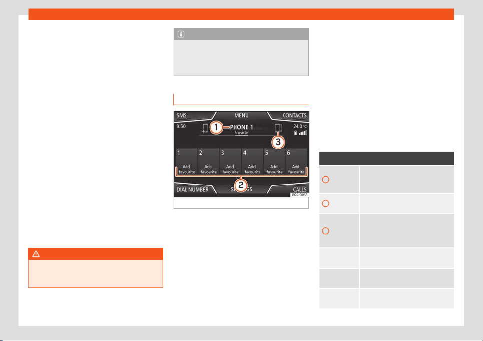
Infotainment System
mobile telephone, the system will try to con-
nect t
o the ne
xt mobil
e t
el
ephone on the list
of pair
ed de
vices.
The maximum range of the connection is ap-
prox. 10 metres. The connection will be inter-
rupted if this distance is exceeded. The con-
nection is automatically re-established as
soon as the device is once again within Blue-
tooth
®
range.
If the maximum number of paired devices is
reached and you want to pair another one,
the system will automatically replace the
least recent one with it. If it is to replace an-
other one, the user must delete that one first.
Do do this:
●
Press the SETTINGS function button in the
telephone context.
●
Press the function button Bluetooth set-
tings > Paired devices.
●
In the list of linked devices, press the func-
tion button after the mobile phone to be
deleted, and then press Delete to confirm
the process.
WARNING
Do not perform the pairing and connection
process while driving. This may cause an
accident!
Note
Check that there are no requests pending
acceptance in your mobile phone. If there
are, this coul
d block some of the functions
in the Telephone menu.
Telephone main menu
Fig. 227
Phone main menu.
Assign a user profile
The phonebook
, the call lists and the speed
dial butt
ons ar
e assigned t
o a user pr
ofil
e and
r
emain stored on the telephone management
system. This information will be available ev-
ery time the mobile telephone is connected.
After the first connection, it will take a few mi-
nutes for the data from the linked mobile
phone to be available in the system. The next
time that the mobile telephone is connected
the phonebook is updated automatically.
If the mobile phonebook has been modified
while connected, a manual update of the
phonebook data can be started from the
User profile settings menu.
Telephone management can store a maxi-
mum of 4 profiles for mobile phones. If you
wish to pair another mobile phone, the oldest
user profile will be replaced.
Telephone management system function
buttons
●
Press the infotainment button to access
the Telephone main menu.
Function button: function
1
Name of connected mobile tele-
phone. Press the icon to the left to
connect another mobile phone
.
2
Speed-dial buttons, connected tel-
ephone contacts favourites.
3
To change to another telephone
connected to the hands-free profile.
Only visibl
e when there are two tele-
phones connected as hands-free.
DIAL NO.
Open the numeric keypad
›››
page 238.
CONTACTS
To open the phonebook of the con-
nected t
elephone.
Text mes-
sage
To open the SMS menu.
236
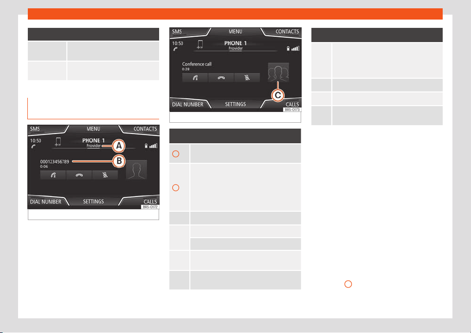
Operating modes
Function button: function
CALLS
To open call lists of the connected
mobile telephone
›››
page 2
41.
SETTINGS
To open the Phone settings
menu.
Instructions and symbols of the
phone management system
Fig. 228
Active call.
Fig. 229 Conference call.
Display: Meaning
›››
Fig. 228
A
Name of the mobile operator of the connec-
ted device.
B
Stored telephone number or name. If the
name stored in the phonebook has an as-
signed photo, it can be displayed: select
Telephone > Settings > User
profile > Show pictures for
contacts*.
To accept a call.
To end a call
.
OR: To
reject an incoming call
.
To mute or to reactivat
e the ring tone during
an incoming call.
To mute the microphone during an active
call and to reactivate it.
Display: Meaning
›››
Fig. 228
The active call is put on hold. While on hol
d
the listener will not hear the conversation. To
reactivate it, pr
ess the call accept button .
To reject it, press the reject button .
Press to add a participant to the active call.
Connected mobile telephone charge status.
Strength of the signal received by the mo-
bile telephone.
Multiple calls
The t
el
ephony management syst
em all
o
ws
the user t
o int
eract with up to three calls on
the screen.
Only one of the calls can be active.
Conference call
The user can merge several calls into a single
one by making a conference call by pressing
button . There must be a minimum of two
calls for this to work. Once the conference
call has started, the user can add up to 5 par-
ticipants.
Once the conference call is established, the
user can consult the list of participants by
pressing on the conference call image
›››
Fig. 229
C
.
Depending on the mobil
e de
vice
, the call
fr
om a conf
er
ence call participant can be
»
237
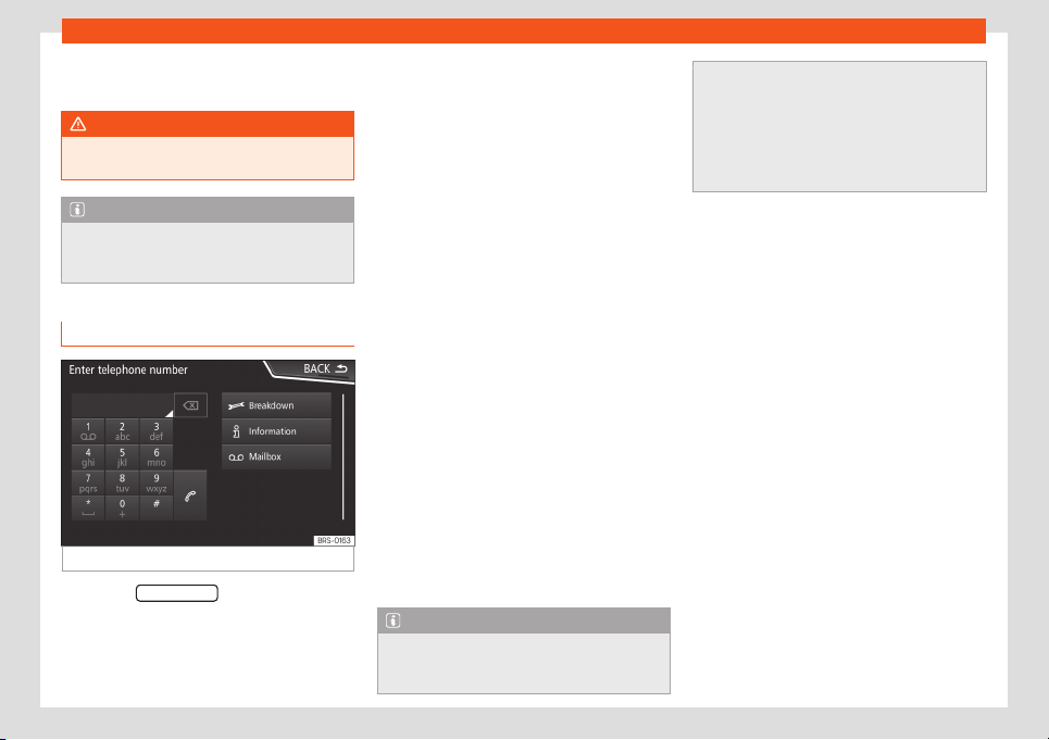
Infotainment System
hung up or excluded from the conference call
but k
ept on a separ
at
e call.
WARNING
Remember that the driver should not oper-
ate the mobile phone while driving.
Note
Multi-call and conference call functionali-
ties are subject to the services associated
with the user's SIM card.
Enter telephone number menu
Fig. 230
Enter telephone number menu.
●
Press the DIAL NUMBER function button from
the T
el
ephone
main menu.
Ent
er t
el
ephone number
●
Ent
er a phone number with the keypad.
Press the function button to make a call.
Select a contact from the list
●
Enter the first few letters of the contact. The
available entries appear in the phonebook.
●
Select the desired contact to make the call.
Enter the country code
●
Press the function button 0 for approx. 2
seconds to add the +.
Assistance call
●
Press the function button to obtain help in
the event of breakdown.
Information call
●
Press the function button to obtain informa-
tion on the SEAT brand and the additional
contracted services.
Call mailbox
●
Press the function button to make the call.
●
OR: Press the function button for about 2
seconds to make a call.
Note
●
Breakdown service and information calls
can incur an additional cost on your tel
e-
phone bill.
●
The Roadside Assistance and Information
services might not work properly, for e
xam-
ple, if the vehicle and the operator of the
connected mobile telephone are in differ-
ent countries. If you are not able to use
these services contact an authorised SEAT
workshop.
238
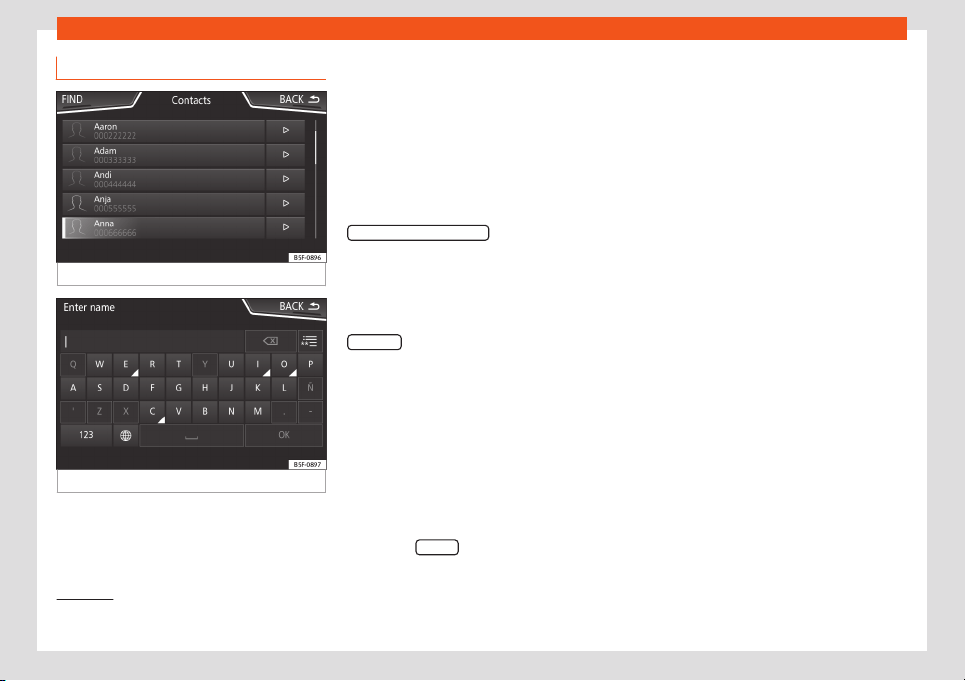
Operating modes
Phonebook Menu (contacts)
Fig. 231
Contacts Menu.
Fig. 232
Search window.
Once the first pairing is made, it may take
some time until the phonebook dat
a
1)
of the
pair
ed mobil
e ar
e av
ail
abl
e in the infotain-
ment system. Depending on the volume of
data that has to be transferred, the process
may take several minutes. It may be necessa-
ry to confirm the data transmission on the
mobile phone.
The phonebook can also be viewed during a
telephone conversation.
If the name saved in the phonebook has an
assigned photo, it can be displayed on the list
next to the name. To do this, the option
Show pictures for contacts
in the Phone set
-
tings
cont
e
xt must be enabl
ed and your mo-
bil
e phone must support this functionalit
y
(check the compatibility list)
›››
page 242,
Phone settings.
In the Telephone main menu, press the
Contacts
function button to access the con-
t
acts list.
Sel
ect a cont
act fr
om the list
●
Sear
ch the list and pr
ess on the desir
ed
contact to make the call.
●
OR: If the contact has several numbers, first
press on the contact and then press on the
desired number for making the call.
Search for a contact in the search window
●
Press the Search
function button
›
›
›
Fig. 231
t
o open the sear
ch windo
w
.
●
Enter the name of the contact you are look-
ing for in the window
›››
Fig. 232. While the
characters are being entered, a contact is
displayed in the input field.
●
The number of matching results is dis-
played to the right of the input field. Press the
function button to go to the list.
●
Search the list and press on the desired
contact to make the call.
Opening the detailed view of a contact
●
Press the function button
›››
Fig. 231 lo-
cated next to the entry on the contacts list.
All the telephone numbers are displayed in
the detailed view, and where applicable, the
address recorded for the contact in question.
Read contact name
●
Press the function button on the detailed
list if you want the voice control system to
read the name of the contact .
Call a contact
●
Press the desired telephone number on the
detailed list to make the call.
●
Press the icon to edit the number before
calling.
»
1)
Depending on the device, only contacts in the
phone's memory are loaded.
239
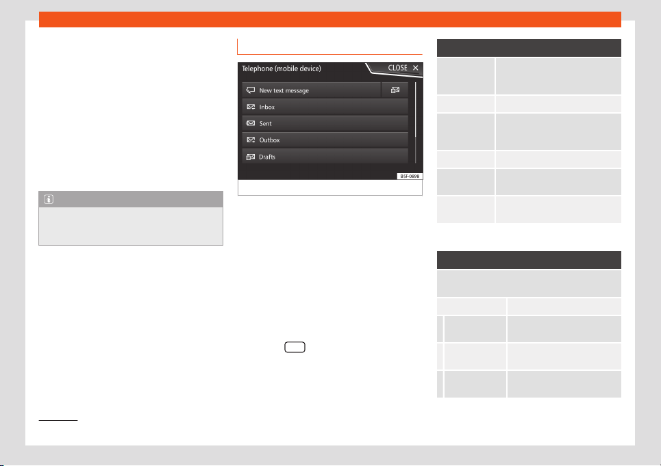
Infotainment System
Send SMS to a contact
●
Press the function button on the det
ail
ed
list.
St
ar
t r
out
e guidance t
o a contact's ad-
dress
1)
If the contact’s address data has been saved,
route guidance can be started to the con-
tact's address.
●
Press address data in the detailed view to
start route guidance.
Note
If you edit a number before calling, it will
not be saved in the phonebook but only
used for the call.
Short messages (SMS) menu
Fig. 233
Short messages (SMS) menu.
If the mobile phone connected to the HFP
pr
ofil
e al
so supports the SMS pr
ofil
e
, a ne
w
function button will appear in the upper left
corner of your Telephone menu, which will al-
low you to receive, view and send SMS mes-
sages through the infotainment system.
Whether or not the aforementioned functions
work correctly will depend on the compatibil-
ity of the connected mobile phone.
SMS menu function buttons
●
Press the SMS
function button from the T
el
-
ephone
main menu.
Function button: function
New text
message
To write and send an SMS (includes
the possibility of accessing preset
text templat
es).
Inbox To open the received SMS folder.
Outbox To open the outbox folder. SMS
messages that have not been sent
are stored here.
Sent T
o open the sent SMS folder.
Drafts To select a message that has been
stored but not sent.
Send contact
det
ail
s
T
o send the details of a contact
fr
om the contact list.
Possible submenu function buttons
Function button: function
READ OUT
For the voice control system to
read the text of the SMS.
Options Open the Options menu.
Reply with
templ
ate
To select a te
xt template from a
list.
Delete current
text message
The SMS is deleted from the
Inbox fol
der.
Telephone
number
The sender's telephone number
is displayed.
1)
Valid for Navi System and Navi System Plus.
240
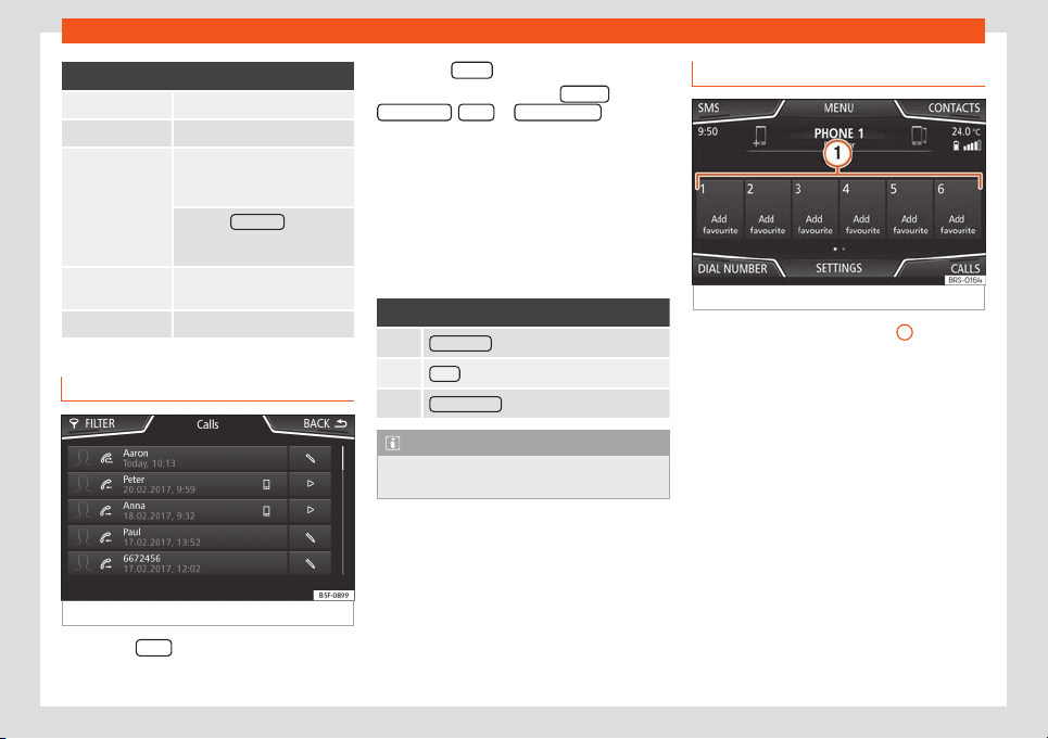
Operating modes
Function button: function
FORWARD To forward an SMS.
REPLY To reply to an incoming SMS.
Enter number
To enter a telephone number or
to select a recipient from the
contact list.
Press the R
ecipients
function
button to select multiple recipi-
ents.
Recipients
T
o select multiple recipients
from the contact list.
Delete To delet
e an SMS.
Calls Menu (call lists)
Fig. 234
Call lists menu.
●
Press the Call
s
function button from the
T
el
ephone
main menu.
●
Pr
ess the FIL
TER
function button.
●
Select the desired call list: All call
s
,
Missed call
s
, Call
s
or R
eceived calls
.
If a t
el
ephone number is st
or
ed in the phone
book
, the sav
ed name is displ
ayed on the call
list instead of the number.
If a photo is assigned to the name stored in
the phonebook, it can be displayed on the
call list next to the name
›››
page 242.
Possible displays in the Calls menu
Display: Meaning
Missed calls : Missed and unanswered calls.
Calls
: Dialled numbers.
Received calls : Received calls.
Note
The availability of the call lists will depend
on the mobile phone used.
Quick dial keys
Fig. 235
Quick access to the phone book.
The speed dial keys
›
›
›
Fig. 235
1
can be
assigned a t
el
ephone number fr
om the
phone book
.
If a phot
o is assigned t
o the name st
ored in
the phone book, it can be displayed on the
speed dial key
›››
page 242.
All speed dial keys have to be manually edi-
ted and will be assigned to a user profile. Up
to 12 contacts can be added to the speed di-
al keys.
Assign the speed dial keys
●
In the main Telephone menu, press a free
speed dial key.
●
Select the desired contact from the list. If
the selected contact has several phone num-
bers, select the number you want.
»
241
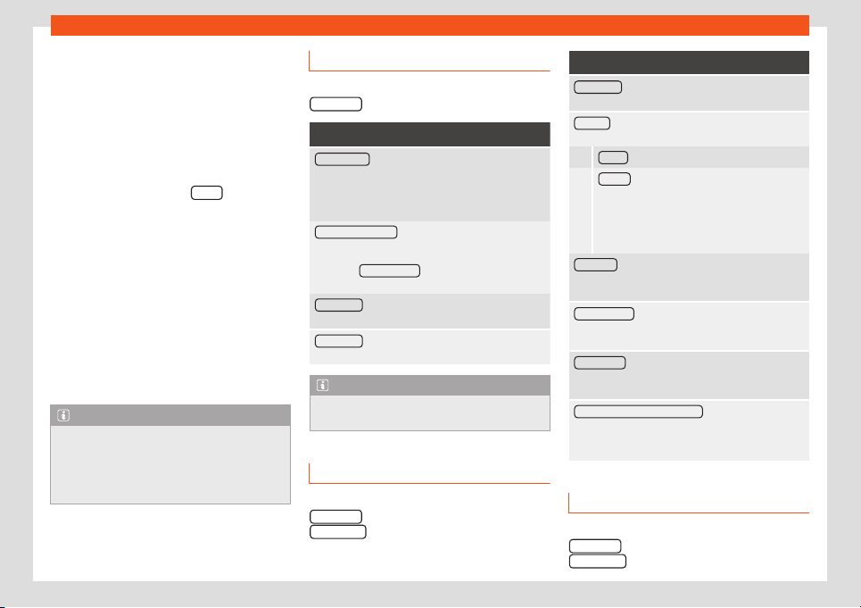
Infotainment System
Edit assigned speed dial keys
●
Press and hold an occupied speed dial k
ey
in the
T
el
ephone
main menu until the
Con-
t
acts menu opens.
●
Select the desired contact from the list. If
the selected contact has several phone num-
bers, select the number you want.
●
To close the Contacts menu without apply-
ing the changes, press the BACK
function
butt
on.
Del
et
e assigned speed dial k
eys
●
The phone numbers st
or
ed in the speed di-
al butt
ons can be deleted in the menu User
profile settings > Manage favourites
›››
page 242.
Make a call with a speed dial button
●
Briefly press an assigned speed dial key in
the Telephone main menu to call the tele-
phone number stored in it.
Note
The contacts stored in the speed dial keys
are NOT updated automatically. If a con-
tact stor
ed on a speed dial key is modified
on the mobile phone, the speed dial key
must be assigned again.
Phone settings
In the Telephone main menu, press the
SETTINGS function button.
Function button: function
Private mode : Private mode can only be activated
during an active call. When private mode is disabled
(by default), the call’s audio is managed through the
vehicle. When private mode is activated, call audio is
managed through the mobile phone.
Select mobile phone : From the list, select the mobile
phone to be connected to the hands-free profile with
the inf
otainment system.
OR: Press Find telephone
to connect a new mobile
phone.
Bluetooth® : Opens the menu Bluetooth® set-
tings
›››
page 242.
User pr
ofile
: Open the User profile settings
menu
›››
page 242.
Note
Some telephones require a restart to down-
load the last added contacts again.
Bluetooth
®
settings
In the main T
el
ephone
menu, pr
ess the
SETTINGS
function button and then press the
Bluet
ooth®
function button.
Function button: function
Bluetooth® : Press to deactivate Bluetooth
®
. All active
connections are disconnected.
Visibility : Activating and deactivating Bluetooth
®
visi-
bility.
Visible : Bluetooth
®
visibility is active.
Hidden : Bluetooth
®
visibility is deactivated.
Bluetooth
®
visibility must be active f
or external
pairing of a Bluetooth
®
device with the infotain-
ment system. When a Bluetooth
®
audio device
is active and playing, visibility is automatically
set to Hidden.
Forename
: Display or change the Bluetooth
®
name of
the infotainment system. This will be the name shown
to other Bluetooth
®
de
vices.
Paired devices
: Viewing paired devices. To disconnect
and connect Bluetooth
®
devices and Bluetooth
®
pro-
files.
Find devices : Search for visible Bluetooth
®
devices
that are within range of the infotainment system. The
maximum
range is approx. 10 meters.
Bluetooth® Audio (A2DP/AVRCP)
: If an external audio
source is to be connected to the infotainment syst
em
via Bluetooth
®
, this function must be active
›››
page 208.
User profile settings
In the main T
el
ephone menu
, pr
ess the
SETTINGS function button and then press the
User pr
ofil
e function button.
242

Operating modes
Function button: function
Manage favourites : Edit the speed dial keys.
Occupied speed dial key: Press to delete the
stored number.
Free speed dial key: Press to save a phone
book number on the speed dial key.
Mailbox number : To enter or change the voice mailbox
number.
Sort by : To set the order of appearance of the phone
book entries (Forname and Surname or vice versa).
Import contacts
: Press to import the phone book of the
connected telephone or to update the imported
phone book
.
Reminder: remember your mobile phone
: If a Bluetooth
®
connection is active with a mobile phone, the mes-
sage “Do not forget your mobile phone”
appears when the ignition is switched off
.
Show pictures for contacts
a)
: If the contacts in the
phone book have been saved with a photo, it can be
displayed on the speed dial k
eys, call lists and
phone book.
a)
Depending on the mobile phone.
Note
Some telephones require a restart to down-
load the last added contacts again.
243
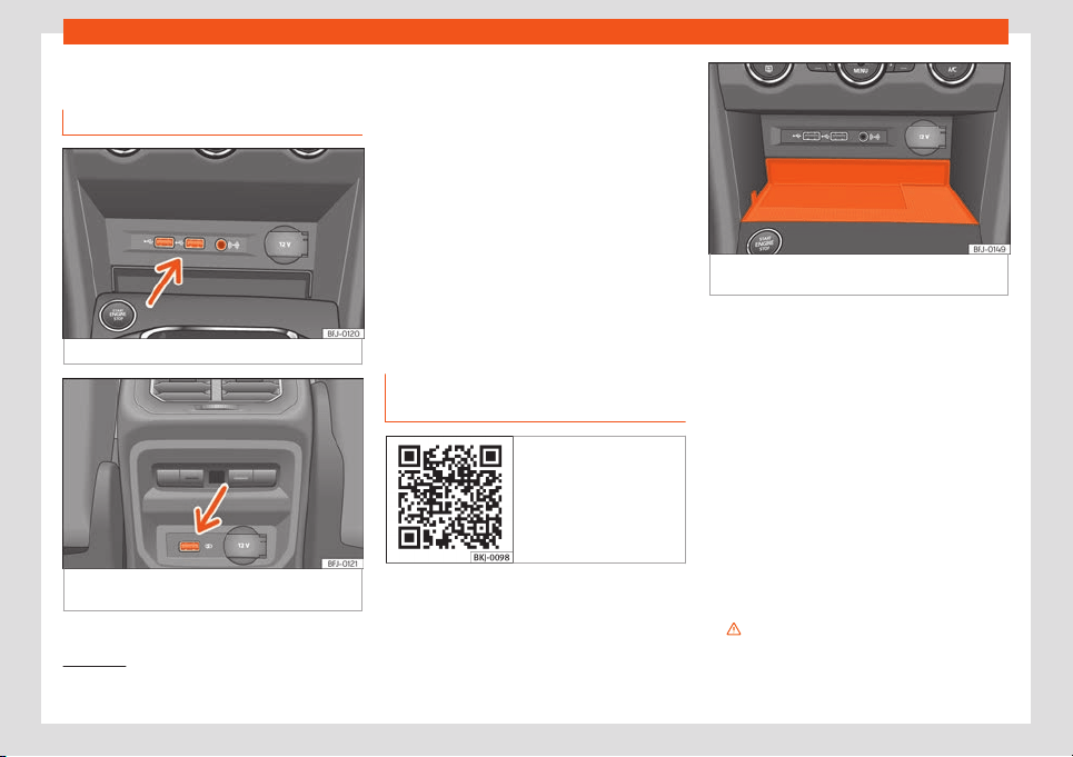
Infotainment System
Multimedia
USB/AUX-IN input
Fig. 236 Centre console: USB/AUX-IN input.
Fig. 237
Rear part of the centre console: USB
connect
ors.
Depending on the special characteristics and
the country, the v
ehicl
e may hav
e a
USB/AUX-IN port.
The USB/AUX-IN port can be f
ound in the
st
or
age compartment ar
ea of the centre
console
›››
Fig. 236.
Depending on the equipment and the coun-
try, the vehicle may also have USB connec-
tions exclusively for charging or as a power
socket.
These USB ports are located at the rear of
the console, between the front seats
›››
Fig. 237.
Connectivity Box* / Wireless
Charger*
Fig. 238 Related video
Fig. 239 In the centre console: pad for the mo-
bile phone connection.
The Connectivity Box includes different func-
tions that will help t
o use your mobil
e de
vice
.
They ar
e the “
Wir
eless Charger” and the
“Mobile Signal Amplifier”.
The Wireless Charger only features the
“Wireless Charger” function.
“Wireless Charger”
The “Wireless Charger” allows mobile devi-
ces with Qi
1)
technology to be charged with-
out a cable.
To charge your mobile phone wirelessly:
●
Place your mobile device in the middle of
the pad with the screen facing up
›››
Fig. 239
›››
.
1)
Qi technology allows you to charge your mo-
bile phone wirelessly.
244
Operating modes
Make sure there are no objects between the
pad and the mobil
e phone
.
The mobil
e phone will st
art char
ging aut
o-
matically. F
or further information about
whether your mobile device uses Qi technol-
ogy, check your phone's user manual or visit
the SEAT website.
“Mobile Signal Amplifier”
The “Mobile Signal Amplifier” allows you to
reduce the radiation in your vehicle and enjoy
better reception.
For safety reasons, it is recommended that
you pair the system and the mobile using
Bluetooth
®
and place it on the Connectivity
Box pad, for the best reception without hav-
ing to handle the mobile phone.
To establish a connection with the vehicle's
external aerial:
●
Place your mobile device in the middle of
the pad with the screen facing up
›››
Fig. 239
›››
.
Mak
e sur
e ther
e ar
e no ob
jects betw
een the
pad and the mobil
e phone.
Your mobile phone will automatically be
ready to make use of the external aerial.
WARNING
●
The mobile phone may heat up due to the
wireless charging. Think about this befor
e
you pick it up, and take care when removing
it.
●
There must be no metallic or other ob-
jects between the mobile phone and the
housing, to prevent the functionalit
y of the
Connectivity Box from being affected.
Note
●
Y
our mobile device must support the Qi
inductive charging int
erface standard for
proper operation.
●
The charging time and the temperature
vary in accordance with the device used.
●
The maximum charging capacity is 5 W.
●
Qi technology does not allow you to
charge more than one mobile device simul-
taneously.
●
No improvement in reception can be
guaranteed if there is more than one mo-
bile phone on the pad.
●
You are advised to keep the engine run-
ning to guarantee proper wireless charg-
ing.
●
When a telephone with Qi technology is
connected by USB, it will be charged by the
means specified by the manufacturer.
245
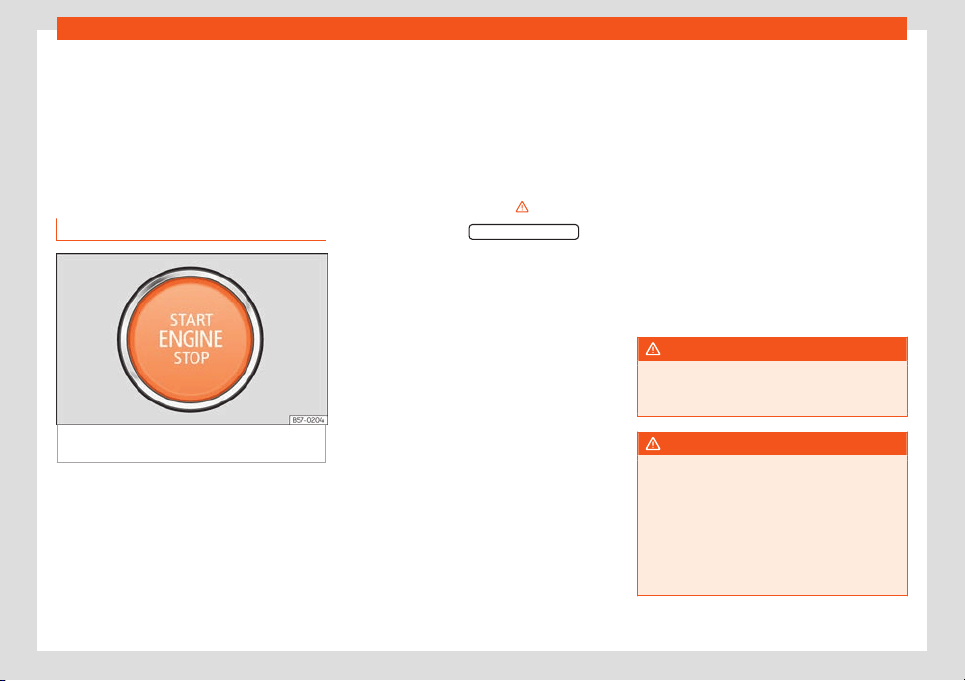
Driving
Driving
St
ar
t and driving
St
ar
ting and st
opping the
engine
Ignition and st
ar
t button
Fig. 240 In the lower part of the centre con-
sol
e: st
art butt
on.
The engine can be started with a start button
(Pr
ess & Driv
e). T
o do so
, ther
e must be a v
alid
k
ey inside the vehicle in the area of the front
or rear seats, or on the centre console.
In vehicles with the Keyless Access
›››
page 89 system, the engine can also be
started with the key in the luggage compart-
ment.
Opening the driver's door when exiting the
vehicle activates the electronic lock on the
steering column if the ignition is disabled.
Switching the ignition on/off manually
If you only want to switch on the ignition
(without starting the engine), briefly press the
start button once without pressing the brake
pedal or the clutch pedal
›››
.
The st
art butt
on t
e
xt S
T
AR
T ENGINE STOP
flash-
es lik
e a heartbeat when the syst
em is r
eady
f
or the ignition t
o be t
urned on or off
.
Automatic ignition disconnection
If the driver leaves the vehicle, taking the key
with them but leaving the ignition on, the igni-
tion does not switch off automatically. The ig-
nition is switched off by pressing the lock but-
ton on the remote control or by pressing
the sensor surface on the door lever
›››
Fig. 79.
Automatic deactivation of the ignition on
vehicles with the Start-Stop system
The ignition is switched off automatically
when the vehicle is stopped and the auto-
matic engine shutdown is active, if:
●
The driver's seat belt is not fastened,
●
the driver does not step on any pedal,
●
the driver door is opened.
After automatically turning off the ignition, if
the dipped beam is on, the side light re-
mains on for approx. 30 minutes (if there is
enough charge in the battery). If the driver
locks the vehicle or manually turns off the
light, the side light goes out.
Engine restart feature
If no key is detected inside the vehicle after
the engine stops, you will only have 5 sec-
onds to restart it. A warning will display on the
dash panel screen.
After this interval, it will not be possible to
start the engine without a valid key inside the
vehicle.
WARNING
When switching on the ignition, do not
press the brake or clutch pedal, otherwise
the engine could st
art immediately.
WARNING
If vehicle keys are used negligently or with-
out due care, this may cause accidents and
serious injury.
●
Never leave any k
ey inside the vehicle
when you leave it. Otherwise, a child or un-
authorised person could lock the vehicle,
start the engine or connect the ignition and
operate any of the electrical equipment.
246
Start and driving
Note
●
Before leaving the vehicle, al
ways dis-
connect the ignition and, if appropriate,
take into account the instructions on the
screen of the dash panel.
●
If the vehicle is stationary for a long time
with the engine off and the ignition on, the
vehicle battery might be discharged and it
might not be possible to start the engine.
●
In vehicles with diesel engines, wait until
the warning light
›››
page 247 goes off
before starting the engine.
●
If during the STOP phase you press the
START ENGINE STOP
button, the ignition is
switched off and the button flashes.
●
If the indication is displayed on the in-
strument panel display “St
art-Stop system
deactivated: Start the engine manually”,
the START ENGINE STOP
button will blink.
Starting the engine
Before starting the engine
●
Vehicles with manual gearboxes: put the
gear l
e
v
er in neutr
al, pr
ess the clut
ch pedal
and k
eep it it in this position until the engine
starts.
●
Vehicles with automatic transmission: put
the lever in position P or N.
Starting the engine
●
Press and hold the brake pedal until the en-
gine starts.
●
Press the starter button
›››
Fig. 240; do not
press the accelerator. There needs to be a
valid key inside the vehicle for the engine to
start. After starting the engine, the lighting of
the START ENGINE STOP
button changes to
st
eady lighting, indicating that the engine has
st
art
ed.
●
Once the engine st
arts, r
el
ease the st
art-up
button.
●
If the engine does not start, stop and wait
for around 1 minute to try again. If necessary,
perform an emergency start
›››
page 249.
Diesel engines can take a few seconds longer
than usual to start on cold days. During pre-
heating, the warning lamp remains lit. To
avoid unnecessary discharging of the bat-
tery, do not use any other major electrical
equipment while the glow plugs are pre-
heating.
The preheating time depends on the coolant
and exterior temperatures. With the engine at
operating temperature, or at outside temper-
atures above +8°C, the warning lamp will
light up for about one second. This means
that the engine starts immediately.
Starting a diesel engine after having run
out of fuel
If the fuel tank has been completely run dry, it
may take longer than normal (up to one mi-
nute) to start a diesel engine after refuelling.
This is because the fuel system must elimi-
nate air first.
WARNING
Do not keep the engine running in confined
spaces, as there is a danger of poisoning.
●
The exhaust gases contain carbon mon-
oxide, an odourless and col
ourless poison-
ous gas that can cause loss of conscious-
ness and death.
WARNING
Do not get out of the vehicle with the en-
gine running, especially if a gear is engag-
ed. The vehicle could then suddenly move
or something strange coul
d happen that
would cause damage, fire or serious injury.
WARNING
Never use cold start sprays, they could ex-
plode or cause the engine to run at high
revs. Doing this risks injury.
CAUTION
●
The starter motor or the engine may be
damaged if you try to star
t the engine while
»
247
Driving
driving or if you restart it immediately after
switching it off.
●
When the engine is cold, you should
avoid high engine speeds, driving at full
thr
ottle and over-loading the engine. Risk
of engine damage.
For the sake of the environment
Do not warm-up the engine by running the
engine with the v
ehicle stationary. Start off
immediately, driving gently. This helps the
engine r
each operating temperature faster
and reduces emissions.
Note
●
Electrical components with a high power
consumption are switched off t
emporarily
when the engine starts.
●
When starting with a cold engine, noise
levels may briefly increase. This is quite
normal, and no cause for concern.
●
When the outside temperature is below
+5 °C (+41 °F), if the engine is diesel, some
smoke may appear under the vehicle when
the fuel-operated auxiliary heater is on.
Turning off the engine
●
Bring the vehicle to a full stop
›
›
›
.
●
With manual tr
ansmission, pr
ess the clut
ch
all the w
ay do
wn. If the v
ehicl
e is automatic,
set the selector lever to the P position.
●
Apply the electronic parking brake.
●
Briefly press the start-up button
›››
Fig. 240.
Emergency disconnection
If the engine does not switch off after briefly
pressing the starter button, an emergency
disconnect will be required:
●
Press the starter button twice within 3 sec-
onds or press it once for more than 1 sec-
ond
›››
in Ignition and start button on
page 2
46
.
WARNING
Never switch off the engine while the vehi-
cle is moving. This could cause loss of con-
trol of the vehicl
e, accidents and serious in-
jury.
●
The airbags and belt tensioners do not
work when the ignition is switched off.
●
The brake servo does not work with the
engine off. Therefore, you need to press the
break pedal harder to brake the vehicle.
●
Power steering does not work when the
engine is not running. You need more
strength to steer when the engine is switch-
ed off.
●
If the ignition is switched off, the steering
column could be lock
ed, making it impossi-
ble to control the vehicle.
●
Never remove the key from the ignition if
the vehicle is in motion. Otherwise, the
steering could suddenly lock, making it im-
possible to steer the vehicle: risk of acci-
dent!
WARNING
Always take the key with you when you
l
eave the vehicle. This is particul
arly impor-
tant if there are children in the vehicle, as
they might otherwise be able to start the
engine or use power-operated equipment
(e.g. the electric windows), which could
cause injuries.
CAUTION
●
If the vehicle is stopped and the Start-
St
op system* switches off the engine, the
ignition remains switched on. Make sure
that the ignition is switched off before leav-
ing the vehicle, otherwise the battery could
discharge.
●
If the engine has been driven at high
speed for a prolonged period of time, it
may overheat when turned off. To avoid en-
gine damage, allow the engine to run for
approximately two minutes in neutral be-
fore switching it off.
248
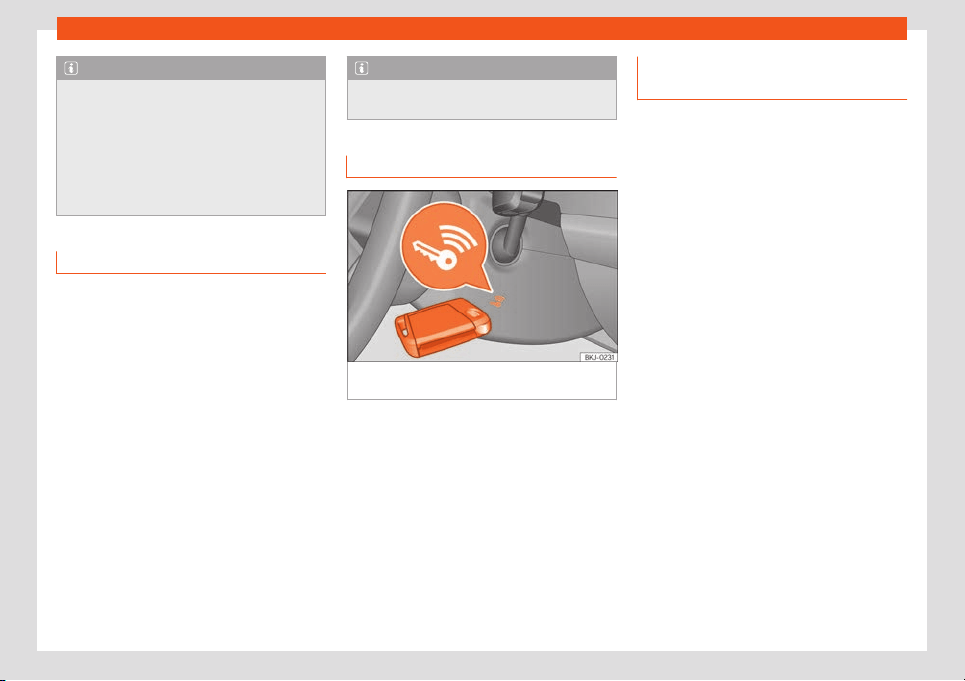
Start and driving
Note
After the engine is switched off the radiator
fan may run on for up to 10 minutes, even if
the ignition is s
witched off. It is also possi-
ble that the fan turns itself on once more if
the coolant temperature increases due to
the heat accumulated in the engine com-
partment or due to its prolonged exposure
to solar radiation.
Electronic immobilizer
The electronic immobiliser prevents unau-
thorised persons fr
om driving the v
ehicl
e
.
Inside the k
ey ther
e is a chip that deactiv
ates
the electronic immobiliser automatically
when the key is inserted into the ignition.
The electronic immobiliser will be activated
again automatically as soon as you pull the
key out of the ignition lock. For vehicles with
the “Keyless Access” system, the key has to
be outside the vehicle.
If the following message is shown on the in-
strument panel display: SAFE, the vehicle
cannot be started.
The engine can only be started using a genu-
ine SEAT key with its correct code.
Note
A perfect operation of the vehicle is ensur-
ed if genuine SEAT keys are used.
Emergency starting function
Fig. 241
On the right of the steering column:
emer
gency st
art.
If no valid key is detected inside the vehicle,
an emer
gency st
art
-up will be r
equir
ed. The
r
el
evant message will appear in the dash
panel display. This may happen when, for ex-
ample, the vehicle key battery is very low:
●
Immediately after pushing the starter but-
ton, keep the key next to the right trim of the
steering column
›››
Fig. 241, as close as pos-
sible to the Kessy logo.
●
The ignition connects and the engine starts
automatically.
Instructions for the driver on the in-
strument panel display
Press the clutch
This message appears on v
ehicl
es with a
manual gearbo
x if the driv
er tries t
o st
art the
engine without having the clut
ch pedal
pressed. The engine will only start if you press
the clutch pedal.
Press the brake
This message appears on vehicles with an
automatic gearbox if the driver tries to start
the engine without having the brake pedal
pressed.
Select N or P
This message appears if you try to start or
stop the engine when the selector lever of the
automatic gearbox is not in position P or N.
The engine can only be started and stopped
in those positions.
Engage position P; the vehicle can
move; doors can only close in po-
sition P.
For safety reasons, this driver message ap-
pears and an audible warning sounds if the
selector lever of the automatic gearbox is not
in position P after you switch off the ignition.
Move the selector lever to the P position, oth-
erwise the vehicle could move.
»
249
Driving
Gear change: selector lever in the
drive position!
This driv
er message is displ
ayed when the
sel
ect
or l
e
v
er is not in the position P when the
driver door is opened. Additionally, a buzzing
sound is emitted. Put the selector lever in po-
sition P, otherwise the vehicle could roll away.
Ignition is switched on
This driver message is displayed and a buz-
zer is sounded when the driver door is
opened with the ignition switched on.
“My Beat” function
Fig. 242 Related video
For vehicles with a convenience key there is
the “My Beat” function. This f
eat
ur
e pr
o
vides
an additional indication of the v
ehicl
e ignition
system.
When entering the vehicle, the start button
›››
Fig. 240 flashes to draw attention to it.
When the ignition is on/off, the engine start
button flashes. With the ignition is switched
off, the start button goes off after a few sec-
onds.
With the engine running, the start button light
stays on, indicating that the engine is running.
The time elapsed between the moment the
user starts the engine with the start button
button and the lighting changes from flashing
to fixed will depend on specific engine size
characteristics. When the start button is used
to stop the engine, the button starts flashing
again.
In vehicles with the Start-Stop system, the
“My Beat” function also offers additional in-
formation:
●
When the engine stops during the Stop
phase, the light of the start button button
stays on, as the Start-Stop system remains
active even though the engine is off.
●
When the engine cannot be started again
with the Start-Stop system,
›››
page 250, and
needs to be started manually, the start but-
ton flashes to indicate this situation.
Start-Stop system*
Control lamps
It lights up
The Start-Stop system is available, the automatic en-
gine shutdown is active.
It lights up
The Start-Stop system is not available or has been
disconnected.
Instructions for the driver on the instru-
ment panel displ
ay
Start-Stop system deactivated.
Start the engine manually
This indication f
or the driv
er sho
ws that the
St
art
-St
op system cannot start the engine
again.
Start-Stop system: Fault! Function
not available
There is a fault in the Start-Stop system. Take
the vehicle to a workshop to have the fault re-
paired.
Description and operation
The Start-Stop system helps you to save fuel
and r
educe CO
2
emissions.
250

Start and driving
In Start-Stop mode, the engine will automati-
cally s
wit
ch off when the v
ehicl
e st
ops or is
st
opping. The ignition r
emains switched on.
The engine automatically switches back on
when required.
In this scenario, the light of the
button stays lit.
When the ignition is s
wit
ched on, the St
art
-
St
op function is aut
omatically activ
ated.
In the Easy Connect system you can find
more information about the Start-Stop sys-
tem: press the button > View > Vehicle
status.
Vehicles with a manual gearbox
●
When the vehicle or when it is stopped, put
it into neutral and release the clutch pedal.
The engine will switch off. The warning lamp
will light up. The engine can be stopped
before stopping completely (approximately 7
km/h).
●
When the clutch pedal is pressed the en-
gine will start up again. The warning lamp will
switch off.
Vehicles with an automatic gearbox
●
Brake until it is stopped, and keep your foot
on the brake pedal or activate the Auto Hold*
system so that the vehicle remains braked.
The engine will switch off. The warning lamp
will appear in the display. The engine can
be stopped before stopping completely (ap-
proximately 7 or 2 km/h depending on the ve-
hicle's gearbox).
●
When you take your foot off the brake ped-
al the engine will start up again. The warning
lamp will switch off. In vehicles with the Auto
Hold* system, when the system is active, the
engine will not start if you remove your foot
from the brake pedal. The car starts when
you press the accelerator pedal.
Basic requirements for the Start-Stop
mode
●
The driver door must be closed.
●
The driver's seat belt must be fastened.
●
The bonnet must be closed.
●
The engine has reached operating temper-
ature.
●
The reverse gear must not be engaged.
●
The vehicle must not be on a very steep
slope.
The engine does not turn off for various
reasons
Before stopping the vehicle, the system veri-
fies whether certain conditions are met. The
engine does not switch off, in the following
situations for example:
●
The engine has not yet reached the re-
quired temperature for the Start-Stop mode.
●
The temperature selected on the climate
control has not been reached.
●
The interior temperature is very high/low.
●
Defrost function button activated
›››
page 152.
●
The parking aid* is switched on.
●
The battery is very low.
●
The steering wheel is overly turned or is be-
ing turned.
●
If there is a danger of misting.
●
After engaging reverse gear.
●
In case of a very steep gradient.
is shown on the instrument panel display,
as well as on the driver information system*
.
The engine starts by itself
When stopped, the normal system mode may
be interrupted in the following situations. The
engine restarts by itself without involvement
from the driver.
●
The interior temperature differs from the
temperature selected on the climate control.
●
Defrost function button activated
›››
page 152.
●
The brake has been pressed several times
consecutively.
●
The battery is too low.
●
High power consumption.
»
251
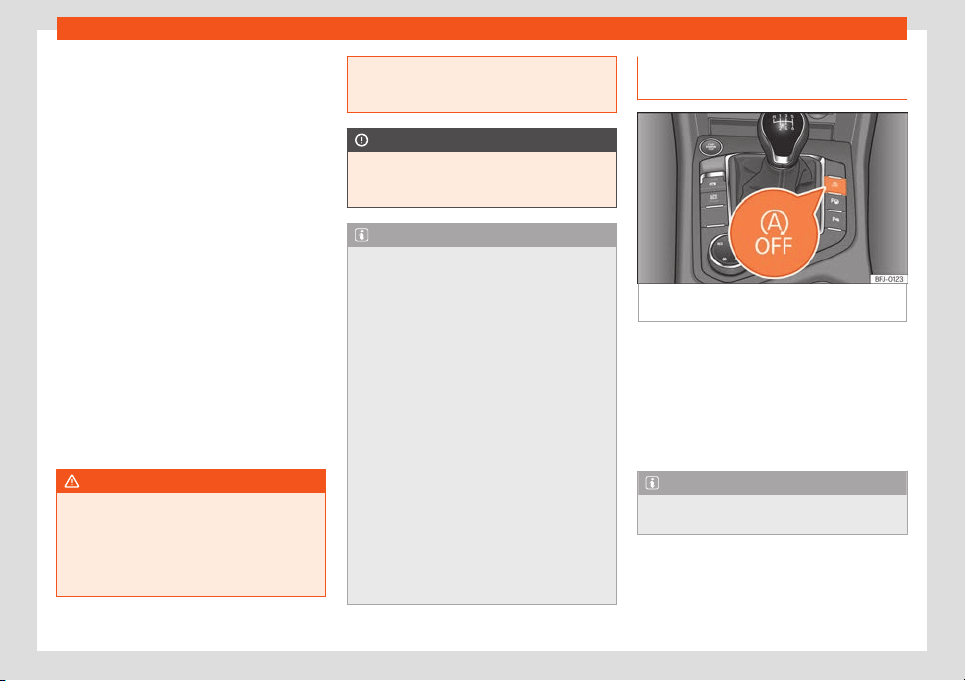
Driving
Additional information related to the auto-
matic gearbo
x
The engine st
ops when the sel
ect
or l
e
v
er is in
the positions P, D, N and S in addition to when
in Tiptronic mode. With the selector lever in P,
the engine will also remain switched off when
you take your foot off the brake pedal. In or-
der to start the engine up again the accelera-
tor must be pressed, or another gear engag-
ed or the brake released.
If the selector lever is placed in R while stop-
ped, the engine will start up again.
Change from D to P to prevent the engine
from accidentally starting when passing
through R.
Additional information about vehicles with
Adaptive Cruise Control (ACC)
In vehicles with ACC function, the engine will
start up again in certain operating conditions
if the radar sensor detects that the vehicle
ahead drives off again.
WARNING
●
Never switch the engine off until the vehi-
cle is st
ationary. The operation of the brake
and steering will not be fully guaranteed.
More force will be needed to turn the steer-
ing wheel or to brake. You could suffer an
accident and even serious injuries.
●
To avoid injury, make sure that the Start
-
Stop system is switched off when working
in the engine compartment
›››
page 252.
CAUTION
The Start-Stop system must always be
s
witched off when driving through flooded
areas
››
›
page 268.
Note
●
In vehicles with an automatic gearbox,
you can control whether the engine should
s
witch off or not by reducing or increasing
the brake force applied. While the vehicle
remains stopped, the engine will not stop if
the brake pedal is slightly pressed, in traffic
jams with frequent stopping and starting
for example. As soon as strong pressure is
applied to the brake pedal, the engine will
stop.
●
When stopped, the brake pedal must be
kept pressed to ensure that the vehicle
does not move.
●
If the engine “stalls” with a manual gear-
box, it can be directly started up again by
immediately pressing the clutch pedal.
●
With an automatic gearbox, if the lever is
placed in position D, N or S after engaging
reverse gear, 10 km/h (6 mph) in a forwards
direction must be reached for the system to
be in a status to stop the engine.
Manually connecting and discon-
necting the St
ar
t
-St
op syst
em
Fig. 243
Centre console: Start-stop system
butt
on.
If you do not wish to use the system, you can
s
wit
ch it off manually.
●
T
o manually s
wit
ch on/off the St
art
-Stop
system, press the button
›››
Fig. 243.
The button symbol remains lit up yellow
when the system is switched off.
Note
The system switches on every time the en-
gine is turned off voluntarily.
252
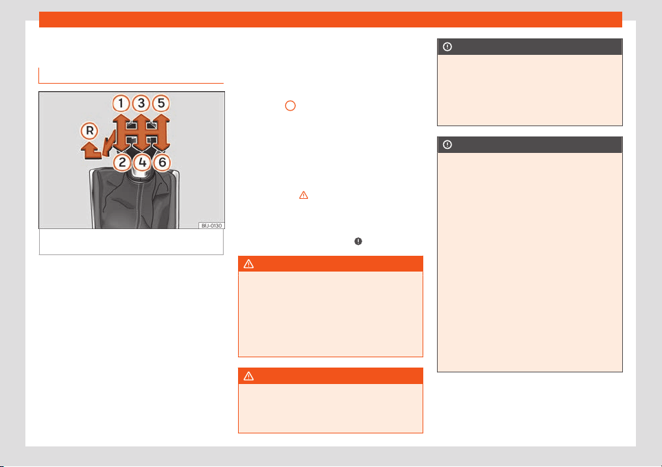
Start and driving
Manual gearbox
Changing gears
Fig. 244 Gear shift pattern of a 6-speed man-
ual gearbo
x
The position of the gears is indicated on the
gearbo
x l
e
v
er
›
›
›
Fig. 244.
●
Press the clutch pedal and keep your foot
right down.
●
Move the gearbox lever to the required po-
sition.
●
Release the clutch.
Selecting reverse gear
Engage reverse gear only when the vehicle is
stopped.
●
Press the clutch pedal and keep your foot
right down.
●
With the gearbox lever in neutral, push it
downwards, move it to the left as far as it will
go and then forwards to select reverse
›››
Fig. 244
R
.
●
Release the clutch.
Changing do
wn gears
Whil
e driving, changing do
wn a gear must al
-
w
ays be done gr
adually, i.e
. to the gear di-
rectly below and when the engine speed is
not too high
›››
. Changing down while by-
passing one or v
arious gears at high speeds
or at high engine speeds can damage the
clut
ch and the gearbo
x, e
v
en if the clut
ch
pedal r
emains depressed
›››
.
WARNING
When the engine is running, the vehicle will
start to move as soon as a gear is engaged
and the clutch r
eleased. This also happens
if the electronic parking brake is switched
on.
●
Never engage reverse gear when the ve-
hicle is moving.
WARNING
If the gear is changed down inappropriate-
ly by selecting a gear that is too low, you
may lose contr
ol of the vehicle, causing an
accident and serious injuries.
CAUTION
When travelling at high speeds or at high
engine speeds, selecting a gear that is too
low can cause considerable damage t
o the
clutch and the gearbox. This can also oc-
cur if the clutch pedal is pressed and held
and it does not engage.
CAUTION
To prevent damage and avoid premature
wear, please observe the follo
wing:
●
Do not rest your hand on the gear lever
while driving. The pressure applied by your
hand is transmitted to the gearbox selector
forks.
●
Do not leave your foot on the clutch ped-
al; although the pressure may seem insig-
nificant, it can cause the premature wear of
the clutch plate. Use the foot rest when you
do not need to change gear.
●
Always ensure that the vehicle is com-
pletely stopped before engaging the re-
verse gear.
●
Always press the clutch to the floor when
changing gears.
●
Never hold the vehicle “on the clutch” on
hills with the engine on.
253
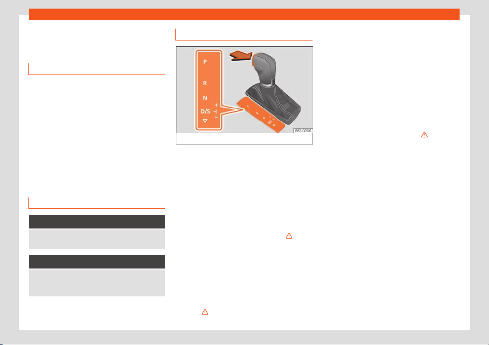
Driving
Automatic gearbox/DSG au-
t
omatic gearbo
x*
Intr
oduction
Your vehicle is equipped with an electronical-
ly controlled manual gearbox. Torque be-
tween the engine and the gearbo
x is trans-
mitted via two independent clutches. They
replace the torque converter found on con-
ventional automatic gearboxes and allow for
smooth, uninterrupted acceleration of the ve-
hicle.
The Tiptronic system allows the driver to
change gears manually
›››
page 256,
Changing gear in Tiptronic mode*.
Control lamps
It lights up green
The brake is not pressed.
To select a gear range, press the brak
e pedal.
Flashes green
The selector lever locking button is not engaged.
The vehicle is prevented fr
om moving forwards. En-
gage the selector lever lock.
Selector lever positions
Fig. 245
Selector lever lock.
The selector lever position is shown when the
corr
esponding sign lights up
. With the sel
ec-
t
or l
e
v
er in the manual gearbox positions M, D
and S, the engaged gear is also shown on the
display.
– Parking lock
When the lever is put in this position, the drive
wheels are locked. The lever must only be put
in P when the vehicle is stationary
›››
.
T
o put the l
e
v
er in
P
or t
ake it out of P , the
locking button must be pressed and held and
the brake pedal pressed simultaneously.
– Reverse gear
Reverse gear must be engaged only when
the vehicle is stationary and the engine is
idling
›››
.
To move the lever to position R, the l
ock but
-
t
on must be pr
essed and hel
d whil
e pr
essing
the brake pedal at the same time. The reverse
lights come on when the lever is in the R posi-
tion with the ignition on.
– Neutral
With the lever in this position, the gear is in
neutral.
Press the brake pedal to move the lever from
N to D/S when the vehicle is stationary or at
speeds below 3 km/h (2 mph)
›››
.
– P
ermanent f
orw
ar
d driv
e position
The l
e
ver in the D/S position enables the
gears to be operated in normal mode (D) or
sport mode (S). To select Sport mode S,
move the lever backwards. Pushing the lever
again will select normal mode D. The selec-
ted driving mode is shown on the instrument
panel display.
In normal mode (D), the gearbox selects the
best gear ratio. This depends on the engine
load, the road speed and the dynamic gear
control programme (DCP).
Sport mode (S) should be selected for a
sporty driving style. This setting makes use of
the engine's maximum power output. When
accelerating the gear shifts will be noticea-
ble.
254
Start and driving
Under certain circumstances (e.g. on moun-
t
ain r
oads) it can be adv
ant
ageous t
o s
wit
ch
tiptronic mode
›››
page 256, to adapt the
gears to suit the road conditions.
Selector lever lock
In P or N, the lever lock prevents a gear range
from being engaged, and prevents the vehi-
cle from moving off accidentally.
To release the gear lever lock, press and hold
the brake pedal with the ignition on. At the
same time, press the lever lock in the direc-
tion of the arrow
›››
Fig. 245.
As a reminder to the driver, when the lever is
in positions P or N the following indication will
be shown on the screen:
When stationary, apply footbrake
while selecting a gear.
The lever is not locked if it is moved quickly
through position N (e.g. when shifting from R
to D). This makes it possible, for instance, to
“rock the vehicle backwards and forwards” if
it is stuck in snow or mud. The lever lock en-
gages automatically if the brake pedal is not
pressed and the lever is in position N for more
than about one second at a speed of less
than 5 km/h (3 mph).
Safety interlock for ignition key
Once the ignition has been turned off, the key
may be removed only if the gear selector is in
position P. While the key is not in the ignition,
the selector lever is locked in position P.
WARNING
●
Take care not to press the acceler
ator
pedal when the vehicle is stopped. The ve-
hicle could start moving immediately (in
some cases even if the parking brake is en-
gaged) resulting in the risk of an accident.
●
Never move the lever to R or P when driv-
ing. Failure to follow this instruction could
result in an accident or failure.
●
With lever in any position (except P), the
foot brake must be pushed down whenever
the engine is running. This is because an
automatic gearbox still transmits power
even at idling speed.
●
While you are selecting a gear and the
vehicle is stopped with the engine running,
do not accelerate. Failure to follow this in-
struction could result in an accident.
●
As a driver you should never leave your
vehicle if the engine is running and a gear is
engaged. Switch on the electronic parking
brake and select the parking lock (P).
Note
●
If the lever is moved accidentally t
o N
when driving, release the accelerator and
let the engine speed drop to idling before
selecting gear range D or S again.
●
Should the power supply to the lever be
interrupted in position P, it will not be possi-
ble to move the lever. If this should happen
the manual release can be used
›››
page 260.
Note
●
If the l
ever lock does not engage, there is
a f
ault. The transmission is interrupted to
prevent the vehicle from accidentally mov-
ing. Follow the procedure below in order for
the lever lock to engage again:
–
With a 6-speed gearbox: press the
brake pedal and release it again.
–
With a 7-speed gearbox: press the
brake pedal. Move the lever to posi-
tion P or N and subsequently engage a
gear.
●
Despite a gear being engaged, the vehi-
cle does not move forwards or back. Pro-
ceed to the next mode:
–
When the vehicle does not move in the
required direction, the system may not
have the gear range correctly engag-
ed. Press the brake pedal and engage
the gear range again.
–
If the vehicle still does not move in the
required direction, there is a system
malfunction. Seek specialist assistance
and have the system checked.
255
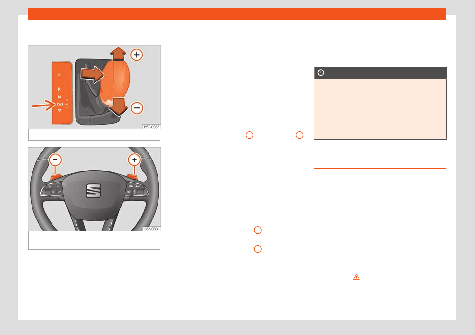
Driving
Changing gear in Tiptronic mode*
Fig. 246
Lever in the Tiptronic position
Fig. 247
Steering wheel: automatic transmis-
sion l
e
v
ers
Tiptronic gives the driver the option to
change gears manually.
When you change t
o the T
iptr
onic pr
o-
gr
amme
, the v
ehicle remains in the currently
selected gear. This is possible as long as the
system is not changing gear automatically
due to a traffic situation.
Using Tiptronic with the selector lever
It is possible to change to Tiptronic mode,
both when the vehicle is stopped and while
driving.
●
Starting from the D/S position, move the
lever to the right. The instrument panel will
show whether the lever is in manual or Tip-
tronic mode (e.g. M4).
●
Push the lever forwards
+
or backwards
–
to move up or down a gear
›
›
›
Fig. 2
46
.
●
T
o e
xit Tiptronic mode, move the lever to the
left.
Using Tiptronic with the steering wheel
paddles*
The gearshift paddles can be used when the
selector lever is in the D/S or M (Tiptronic)
positions.
●
Press the gearshift paddle
+
to select a
higher gear
›
›
›
Fig. 2
47
.
●
Pr
ess the gearshift paddl
e
–
to select a
l
o
w
er gear
.
●
T
o e
xit the T
iptronic mode, pull the right-
hand lever towards the steering wheel for ap-
proximately 1 second or move the lever to the
left.
If the paddles are not operated for some time
and the lever is not in the Tiptronic selection
position, it will automatically exit from Tip-
tronic mode.
CAUTION
●
When accelerating, if a higher gear is not
selected, it will automatically change
shortly bef
ore reaching the maximum per-
mitted RPM.
●
Also, if a lower gear is selected, the sys-
tem will not change until it detects that the
engine will not reach its maximum RPM.
Driving with an automatic gearbox
The gearbox changes gear ratios automati-
cally as the v
ehicl
e mo
v
es.
The engine can only st
art with the sel
ect
or
lever in position P or N. At low temperatures,
below -10 °C (+14 °F), the engine can only
start with the selector lever in position P.
Driving down hills
Under certain circumstances it may be ad-
vantageous to use the Tiptronic mode to se-
lect the gear manually according to driving
conditions
›››
.
256
Start and driving
Stop/Park
On l
e
v
el gr
ound, just use the l
e
v
er to engage
position P. On slopes you should first apply
the parking brake and then set the lever to P.
This makes it easier to remove the lever from
position P when starting.
If the driver door is opened and the lever is
not in position P, the vehicle could move. The
following warning is displayed on the instru-
ment panel: Gear change: selector
lever in the drive position!. Addi-
tionally, a buzzer will sound.
Stopping on a downhill
Always apply the brake pedal firmly to pre-
vent the vehicle from moving; if necessary,
apply the electronic parking brake
›››
.
Do not accel
er
at
e whil
e a r
ange of gears is
engaged t
o pr
event the car from rolling
downhill
›››
.
St
ar
ting off uphill with the Aut
o Hol
d func-
tion
●
Once you hav
e engaged a gear
, t
ake your
foot off the brake pedal and gently press the
accelerator.
Starting off uphill without the Auto Hold
function
●
Pull on the electronic parking brake button.
●
Once you have engaged a gear, gently
press the accelerator and pull on the elec-
tronic parking brake button.
Back-up programme
If all the positions of the lever are shown over
a light background on the instrument panel
display, there is a system fault and the auto-
matic gearbox will operate in with the backup
programme. It is still possible to drive the ve-
hicle, however, at low speeds and within a se-
lected range of gears. Driving in reverse
gear may not be possible.
Kick-down
The kick-down system provides maximum ac-
celeration when the gear selector lever is in
the positions D, S or in the Tiptronic position.
When the accelerator pedal is pressed right
down, the automatic gearbox will shift down
to a lower gear, depending on road speed
and engine speed. This takes advantage of
the maximum acceleration of the vehicle
›››
.
The upshift t
o the ne
xt higher gear is del
ayed
until the engine r
eaches maximum rpm.
WARNING
Observe the safety warnings
›››
in Selec-
tor lever positions on page 255.
●
Nev
er allow the brake to rub and do not
use the brake pedal too often or for long
periods, as the brakes can overheat. This
reduces the braking power, increases the
br
aking distance or even causes a brake
system fault.
●
If you have to stop on a hill, keep the vehi-
cle’s brakes applied with the brake pedal or
parking brake.
WARNING
Please note that if the road surface is slip-
pery or w
et, the kick-down feature coul
d
cause the driving wheels to spin, which
could result in skidding.
CAUTION
●
If you stop the vehicle on a gradient, do
not attempt to st
op it from rolling by de-
pressing the accelerator when a gear has
been selected. This could cause overheat-
ing and damage the automatic gearbox.
●
If you allow the vehicle to roll with the
lever in position N and the engine off, the
automatic gearbox will be damaged by
lack of lubrication.
●
In certain driving situations or traffic con-
ditions, the gears could overheat and be
damaged! If the warning lamp lights up,
stop the vehicle as soon as you can and
wait for the gearbox to cool
›››
page 259.
»
257
Driving
●
If the gearbox operates with the backup
programme
, take the vehicle to a special-
ised workshop and have the fault repaired
without delay.
Launch-control program
3 Value for vehicles: diesel with power of more
than 125 kW, and petrol of more than 140 kW.
The Launch-contr
ol programme enables
maximum acceleration from a standstill.
Condition: the engine must have reached op-
erating temperature and the steering wheel
must not be turned.
The engine speed for Launch-control is differ-
ent on petrol and diesel engines.
To use the Launch-control you must discon-
nect the anti-slip regulation (ASR) through the
Easy Connect system menu
›››
page 82. The
warning lamp will stay switched on or will
flash slowly depending on whether or not the
vehicle has a driver information system*.
On vehicles with the driver information sys-
tem, the ESC lamp lights up permanently and
the corresponding text message Stability
control deactivated (temporary) appears
on the instrument panel to indicate the deac-
tivation stat
us.
●
With the engine running, switch off traction
control (ASR)
›››
page 304
1)
.
●
Press the brake pedal with your left foot
and hold it down for at least one second.
●
Turn the selector lever to position S or Tip-
tronic, or else select the sport driving mode
from the SEAT Drive Profile*
›››
page 263.
●
With your right foot, press the accelerator
down to the full throttle or kick-down position.
The engine speed will stabilise at about
3,200 rpm (petrol engine) or about
2,000 rpm (diesel engine).
●
Take your left foot off the brake pedal. The
vehicle starts with maximum acceleration.
WARNING
●
Always adapt your driving style to the
traffic conditions.
●
Only use the L
aunch control programme
when road and traffic conditions permit,
and make sure your manner of driving and
accelerating the vehicle does not incon-
venience or endanger other road users.
●
Make sure that the ESC remains switched
on. Please not
e that when the ASR and ESC
are deactivated, the wheels may start to
spin, causing the vehicle to lose grip. Risk
of accident!
●
After moving off, the ESC “sport” mode
should be deactivated by briefly pressing
the button.
Note
●
Aft
er using the Launch control pro-
gramme, the t
emperature in the gearbox
may have increased considerably. In this
case, the programme could be disabled for
several minutes. The programme can be
used again after the cooling phase.
●
Accelerating with the launch control pro-
gramme places a heavy load on all parts of
the vehicle. This can result in increased
wear and tear.
Downhill assistant*
Downhill speed control is activated when the
l
e
v
er is in the
D/S
position and the br
ak
e is
applied. An appropriate lower gear is engag-
ed.
1)
Vehicles without a driver information system:
the warning lamp flashes slowly. Vehicl
es with a
driver information system: the warning lamp re-
mains on.
258
Start and driving
The assistant attempts to maintain the speed
at which the v
ehicl
e w
as tr
av
elling when the
br
ak
e was applied, within logical limits. It may
be necessary to correct the speed by press-
ing the brake.
The assistant can only change down as far
as 3rd gear. It is possible that on very steep
slopes you have to switch to tiptronic mode
and change down to 2nd or 1st gear to take
advantage of engine braking and take the
load off the brake system.
Downhill speed control is deactivated as
soon as the road levels out again or you press
the accelerator pedal.
On vehicles with cruise control system*
›››
page 268, downhill speed control is acti-
vated when you set a cruising speed.
WARNING
The downhill speed control cannot defy the
laws of physics. Therefore, speed cannot
be maintained const
ant in all situations. Al-
ways be prepared to use the brakes!
Inertia mode
The inertia mode allows you to travel certain
dist
ances without using the accel
er
at
or
,
which sav
es fuel. Pl
an ahead and use the in-
ertia mode to “let” the vehicle “roll”.
Activation of the inertia mode
Condition: lever in position D, slopes of less
than 12% and speeds between 20 and 130
km / h (12 and 80 mph).
●
Gently take your foot off the accelerator.
The indication will be shown on the instru-
ment cluster , the engaged gear and cur-
rent consumption will disappear and the
word Inertia will appear.
The gears will automatically disengage and
the vehicle will roll freely, without the effect of
the engine brake. While the vehicle rolls, the
engine runs at idling speed.
Stopping inertia mode
●
Press the brake or the accelerator pedal.
To take advantage of the engine's inertia
mode, simply remove your foot from the ac-
celerator.
Applying both the inertia mode (= prolonged
section with less energy) and inertia discon-
nection (= shorter section without the need
for fuel) facilitates improved fuel consumption
and emission balance.
If the vehicle has SEAT Drive Profile
›››
page 263, the inertia mode can be activa-
ted in Normal, Eco and Individual modes. In
Eco mode, it is activated whenever the oper-
ating conditions are met, regardless of the
smoothness with which the foot is removed
from the accelerator.
WARNING
●
If the inertia mode has been switched on,
take into account, when appr
oaching an
obstacle, that the vehicle will not deceler-
ate in the usual manner: risk of accident!
●
When using inertia mode while travelling
down hills, the vehicle can increase speed:
risk of accident!
●
If other users drive your vehicle, warn
them about inertia mode.
Note
●
The driver message Inertia is only dis-
played with the current consumption. In in-
ertia mode the gear will no longer be dis-
pl
ayed (for example “D” or “E” will appear
instead of “D7” or “E7”).
●
The inertia mode will be automatically
disconnected on gradients steeper than
15%.
Indications on the instrument panel
displ
ay
Clutch
Clutch overheating! Please stop!
The clut
ch has o
v
erheat
ed and coul
d be
damaged. St
op and w
ait for the gearbox to
»
259
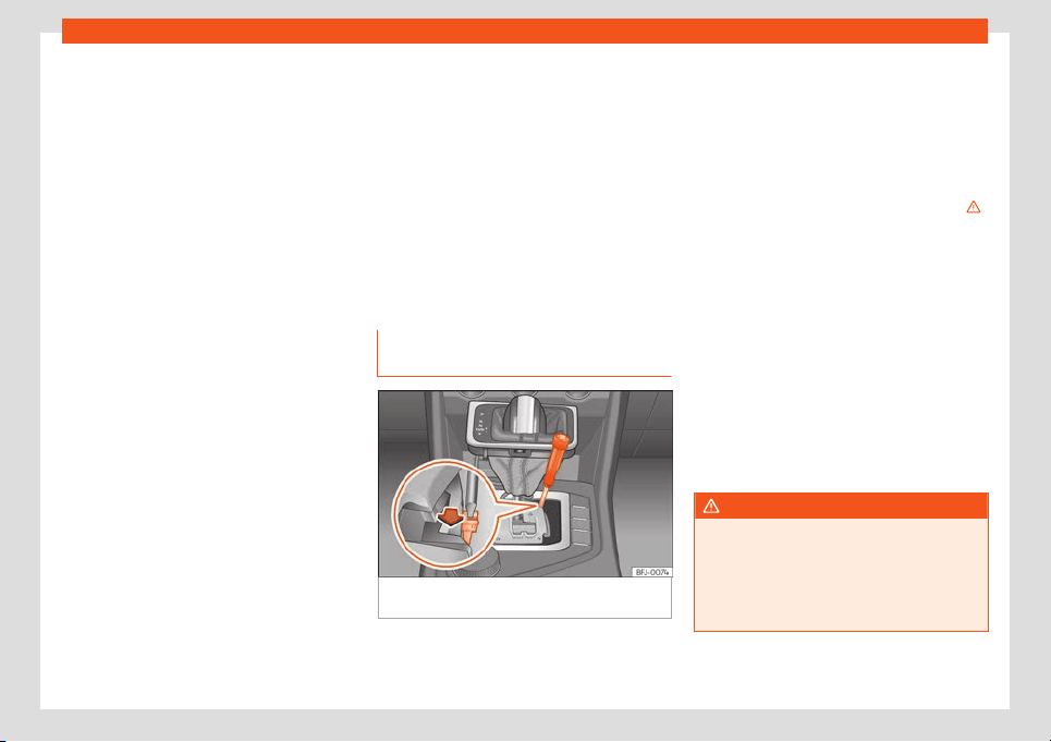
Driving
cool with the engine at idling speed and the
sel
ect
or l
e
v
er in position
P
. When the warning
lamp and the driver message switch off, have
the fault corrected by a specialised work-
shop without delay. If they do not turn off, do
not continue driving. Seek specialist assis-
tance.
Faults in the gearbox
Gearbox: Fault! Stop the vehicle
and place the lever in the posi-
tion P.
There is a fault in the gearbox. Stop the vehi-
cle in a safe place and do not continue driv-
ing. Seek specialist assistance.
Gearbox: System fault! You may
continue driving.
Have the fault corrected by a specialised
workshop without delay.
Gearbox: System fault! You can
continue driving with restric-
tions. Reverse gear disabled
Take the vehicle to a specialised workshop
and have the fault repaired.
Gearbox: System fault! You can
continue driving in D until
switching off the engine
Park the vehicle in a safe place. Seek special-
ist assistance.
Gearbox: too hot. Adapt your
driving accordingly
Continue driving at moderate speeds. When
the warning lamp switches off, you can con-
tinue driving in a normal manner.
Gearbox: press the brake and en-
gage a gear again.
If the warning was caused by the tempera-
ture of the gearbox, this driver message will
be displayed when the gearbox has cooled
again.
Manual release of the selector lev-
er
Fig. 248
Gear selector lever: manual release
fr
om the parking position.
In the event of a power failure when starting
(e
.g. dischar
ged batt
ery), the l
e
v
er will r
emain
locked in position P. To move it to position N to
move the vehicle, there is an emergency re-
lease device under the centre console, on the
right side. Releasing the selector lever re-
quires a certain degree of practical skill.
Removing the cover from the selector lev-
er
●
Apply the electronic parking brake
›››
.
●
Carefully pull the corners of the selector
l
e
v
er boot and twist it up
w
ar
ds o
ver the lever
handle.
Releasing the selector lever
●
Using the flat part of a screwdriver, press
the yellow tab sideways and keep it pressed
down
›››
Fig. 248.
●
Press the lock button on the selector lev-
er and move it to position N.
●
After completing the emergency release,
reattach the selector lever boot to the gear-
box console.
WARNING
Do not move the lever from position P if the
parking brake is not firmly engaged. If you
still think the car could move, pr
ess the
brake pedal. Danger! The vehicle could
move in an unforeseen way and cause an
accident or serious injury.
260

Start and driving
Gear-change recommenda-
tion
Sel
ecting the optimal gear
Depending on the equipment on the instru-
ment panel screen, a recommendation is
shown with the gear that should be engaged
to optimise consumption.
On vehicl
es with automatic transmission, the
lever must be in Tiptronic mode
›››
page 256.
No recommendation will appear if the opti-
mal gear is engaged. The current gear will be
displayed.
Display Meaning
Optimum gear.
Changing to a higher gear is rec-
ommended.
Changing to a lower gear is rec-
ommended.
Information regarding the “cleanliness” of
the par
ticul
at
e filt
er
When the e
xhaust syst
em det
ects that the
particulate filter is close to saturation, this
system’s self-cleaning function recommends
the optimal gear for that function
›››
page 348.
WARNING
The gear change recommendation is an
auxiliary function and in no case should be
a substitute for careful driving.
●
Responsibilit
y for selecting the correct
gear, depending on the circumstances,
rests solely with the driver.
For the sake of the environment
Selecting the correct gear can help to save
fuel.
Note
The recommended gear indication turns off
when the clutch pedal is pressed or when
the lever is remo
ved from the tiptronic posi-
tion.
Hill Descent Control (HDC)
Contr
ol l
amps
3 Valid for vehicles: 4Drive all-wheel drive
It lights up white
Hill Descent Control is active.
It lights up grey
Hill Descent Control is not active. The system is
switched on, but is not adjusting.
Some control and warning lamps will light up
briefly when the ignition is switched on to
check certain functions. They will switch off
aft
er a few seconds.
WARNING
Observe the safety warnings
›››
in Con-
trol and warning lamps on page 81.
Description and operation
Hill Descent Control limits the speed on steep
descents by aut
omatically br
aking all f
our
wheel
s, both when mo
ving f
orw
ard and in re-
verse. As the anti-lock brake system remains
active, it prevents the wheels from locking. In
vehicles with manual transmission, the Hill
Descent Control adapts the theoretical
speed without slowing the engine below its
idling speed.
After starting the descent of a slope below
30 km/h (18 mph), speed is limited to a mini-
mum of 2 km/h (1 mph) and a maximum of
30 km/h (18 mph). When appropriate, the
driver may increase or decrease the speed
within the limit by pressing the accelerator or
the brake. At this point the function is
»
261

Driving
interrupted and, if necessary, it is then reacti-
v
at
ed.
Ev
en so
, it is imper
ativ
e that the surf
ace guar-
antees sufficient adhesion. For this reason,
the Hill Descent Control will not fulfil its func-
tion when, for example, descending a slope
with a frozen or slippery surface.
Hill Descent Control is available when the
dash panel display shows the message .
Hill Descent Control automatically intervenes
if the following conditions are met:
●
The vehicle engine is running.
●
The Offroad driving profile has been selec-
ted
›››
page 263. Driving at a speed below
30 km/h (18 mph) (the message is shown
on the instrument panel).
●
The slope of the descent is at least 10%
when driving forward and 9% when driving in
reverse.
●
The brake and the accelerator are not
pressed.
Hill Descent Control is deactivated on press-
ing the brake and the accelerator or if the
slope is below 5%. The function may be dis-
connected manually in the Easy Connect
system by pressing the > HDC button.
WARNING
Always be ready to brake. Otherwise, an
accident could occur and cause injury.
●
Hill Descent Control is only an auxiliary
system that in some situations may not suf-
ficiently brake the v
ehicle when going
down a slope.
●
The speed of the vehicle may increase
despite the intervention of Hill Descent
Control.
Steering
Information relating to different v
e-
hicle processes.
Electro-mechanical power steering adapts
el
ectr
onically
t
o the speed of the car
, t
or
que
and steering angle.
If the power steering should fail at any time or
the engine is switched off (for instance when
being towed), the car can still be steered.
However, much more effort than normal will
be required to turn the steering wheel.
Progressive steering
Depending on the vehicle’s features, it may or
may not incorporate a progressive steering
system.
In city traffic you do not need to turn so much
on parking, manoeuvring or in very tight turns.
On the road or on the motorway, progressive
steering transmits, for example, in bends, a
sportier, more direct and noticeably more dy-
namic driving sensation.
Steering assist
This help assists the driver in critical situa-
tions. It recommends turning the steering
wheel to perform a corrective manoeuvre
(counter-steering), turning slightly to avoid
skidding
›››
.
WARNING
Steering assist helps the driver in critical
situations. The driver is the person who has
to control the vehicle's st
eering at all times.
Control lamp
It lights up red
Faulty steering.
Do not continue driving, stop the vehicle as soon as
possible and in a safe manner.
T
ake the vehicle to a specialised workshop and have
the fault repaired as soon as possible.
262

Start and driving
It lights up yellow
Limited steering operation.
Drive carefully to a specialised workshop to have the
st
eering checked.
If the warning light does not come on again after re-
starting the engine and driving a short distance, it is
not necessary to check the steering.
OR: The 12-volt battery was disconnected and re-
connected.
Driv
e a short distance at 15-20 km / h (9-12 mph).
It flashes yellow
The steering column is jammed.
When stopped, turn the steering wheel in both direc-
tions.
OR: The steering column does not unl
ock or lock.
Remove the key from the ignition s
witch and recon-
nect it. Consider the messages shown on the instru-
ment panel display.
Do not continue driving if the steering column re-
mains locked after switching on the ignition. Seek
specialist assistance.
The control lamp should light up for a few
seconds when the ignition is s
wit
ched on. It
shoul
d go out once the engine is st
art
ed.
WARNING
Never ignore the warning lamps or messag-
es.
●
If the warning lamps and the correspond-
ing messages are ignored, the vehicle may
stall in traffic, causing serious damage or
accidents and injuries.
●
Stop the vehicle at the next opportunity
and in a safe place.
SEAT Driving modes (SEAT
Drive Profile)*
Introduction
The SEAT Drive Profile enables the driver to
choose betw
een the
Eco,
Normal,
Sport and
Individual pr
ofil
es and modes, which modi-
fy the behaviour of v
arious vehicle functions,
providing different driving experiences.
In addition, the 4Drive version features the
Offroad and Snow profiles.
The Individual profile can be configured
according to personal preferences. The other
profiles have a fixed configuration.
Description
Depending on the equipment fitted in the ve-
hicl
e
, SEAT Driv
e Pr
ofil
e can oper
at
e on the
following functions:
Engine
Depending on the profile selected, the engine
responds more quickly or smoothly to the ac-
celerator being pressed. When Eco mode is
selected, the Start-stop function is activated.
In vehicles with automatic transmission, the
gear change timing is changed to put the
changes at higher or lower revolutions. Eco
mode activates the Inertia function, thereby
reducing consumption. The rest of the driving
modes will activate the inertia use function
when the selector lever is not in the S posi-
tion, depending on how the accelerator ped-
al is released
›››
page 259. When the vehicle
is turned on again, the function is activated
by default to reduce consumption.
With a manual gearbox, the Eco mode
changes the gear changes recommenda-
tions to facilitate more efficient driving.
Dynamic chassis control (DCC)
DCC continuously adapts the shock absorb-
ers to the condition of the road and current
driving conditions, according to the pre-set
programme.
In the event of a fault in the DCC, the follow-
ing message is displayed on the instrument
screen Fault: shock absorber regula-
tion
»
263
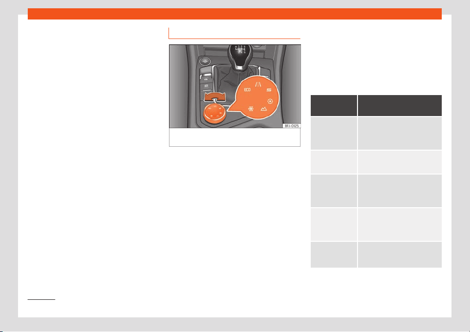
Driving
Steering
The po
w
er st
eering v
aries its driving modes
and adapts t
o the pr
ofil
e selected, thus offer-
ing the best behaviour for each situation.
Air conditioning
In vehicles with Climatronic, this can operate
in eco mode, especially restricting fuel con-
sumption.
Adaptive Cruise Control (ACC)
The ACC’s acceleration and braking mode
varies according to the driving profile
›››
page 277.
Electronic Stability Control (ESC)
In the Offroad and Snow driving profiles, the
electronic stability Control (ESC)
›››
page 302 adjusts to adapt to the terrain.
In addition, hill descent control (HDC) is acti-
vated in the Offroad profile
›››
page 261.
PreCrash system
The PreCrash system adapts according to
the selected configuration. The Sport and
Offroad driving profiles have specific set-
tings to adapt them to driving and terrain
characteristics
›››
page 22.
Setting the driving profile
Fig. 249
Centre console: Driving Experience
butt
on.
You can select the Eco, Normal, Sport, Indi-
vidual, Offroad
1)
and Snow
1)
.
The desir
ed mode can be sel
ect
ed as f
oll
o
ws:
●
T
urn the Driving Experience button until the
required profile lights up on the Easy Connect
system display as well as on the Driving Ex-
perience button
›››
Fig. 249.
●
OR: select the required profile on the touch-
screen of the Easy Connect system, in the
menu that opens up on turning the Driving
Experience button.
The features of each profile can be seen by
pressing the Profile information function
button.
In the Individual profile it is possible to con-
figure the characteristics of the vehicle using
the Profile setup function button.
An icon on the touchscreen provides informa-
tion about the active profile if it is different
than Normal. The selector identifies the pro-
file chosen by means of a yellow LED light.
Driving pro-
file
Characteristics
Places the vehicl
e in a low state
of consumption, facilitating a
fuel-saving driving style that is
respectful t
o the environment.
Normal
Offers a balanced driving experi-
ence, suitable for everyday use
.
Sport
Provides a complete dynamic
perf
ormance in the v
ehicl
e
, ena-
bling the user a mor
e sport
y driv-
ing st
yle.
Individual
It allows you to personalise the
configur
ation. The functions that
can be adjusted depend on the
equipment fitted in the vehicle.
Offroad
a)
It adjusts the v
ehicle's parame-
ters in order to maintain optimal
off-road driving.
1)
Only for 4Drive models.
264
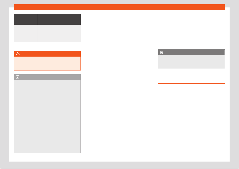
Start and driving
Driving pro-
file
Characteristics
Snow
a)
It adjusts the vehicle's behaviour
f
or driving on slippery road sur-
faces, optimising grip and ma-
noeuvrability.
a)
Only for 4Drive models.
WARNING
When operating SEAT Drive Profile, pay at-
tention to all traffic: doing otherwise could
cause an accident.
Note
●
When the engine is switched off it will
store the driving profile that w
as selected
when the ignition was turned off. When re-
starting, the engine and gearbox start up in
their normal mode. For engine and gear to
revert to the desired mode, select the cor-
responding drive profile again rotating the
thumbwheel (Driving Experience Button) or
on the Easy Connect display.
●
When the vehicle is restarted after using
the Offroad or Snow settings, the system is
always activated in the Normal profile.
●
Your speed and driving style must always
be adjusted to visibility, weather, and traf-
fic conditions.
●
The Eco profile is not recommended when
towing a vehicle.
Driving tips
Running in
Please observe the instructions for running-in
new components.
Running-in the engine
A new engine must be driven through a run-in
period during its first 1500 kilometres (
1000
miles). During its first few hours of running, the
internal friction in the engine is greater than
later on when all the moving parts have bed-
ded down.
How the vehicle is driven for the first 1500 km
(1000 miles) influences the future engine per-
formance. Throughout the life of the vehicle, it
should be driven at a moderate speed (espe-
cially when the engine is cold) this will reduce
engine wear and increase its useful life. Never
drive at extremely low engine speeds. Always
engage a lower gear when the engine works
“irregularly”. For the first 1000 km or
600 miles, please note:
●
Do not use full throttle.
●
Do not force the engine above two thirds of
its maximum speed.
●
Do not tow a trailer.
Between 1000 and 1500 kilometres (600
to 1000 miles),
gradually increase power
until reaching the maximum speed and high
engine speeds.
Running in new tyres and brake pads
●
Replacement of wheel rims and new tyres
›››
page 364.
●
Information about brakes
›››
page 298.
For the sake of the environment
If the engine is run in gently, the life of the
engine will be increased and the engine oil
consumption reduced.
Four-wheel drive (4Drive)
3 Valid for vehicles: 4Drive all-wheel drive
On four-wheel drive models, the engine po
w-
er is distributed to all four wheels
General notes
On four-wheel drive vehicles, the engine
power is distributed to all four wheels. The
distribution of power is controlled automati-
cally according to your driving style and the
road conditions. Also see
›››
page 302.
The four-wheel drive is specially designed to
complement the superior engine power. This
combination gives the vehicle exceptional
handling and performance capabilities, both
on normal roads and in more difficult condi-
tions, such as snow and ice. Even so (or
»
265
Driving
perhaps especially for this reason), it is im-
port
ant t
o observ
e cert
ain saf
et
y points
›
››
.
Wint
er t
yr
es
Thanks t
o f
our
-wheel driv
e, your vehicle will
have plenty of traction in winter conditions,
even with the standard tyres. Nevertheless,
we still recommend that winter tyres or all-
season tyres be fitted on all four wheels to
give even better braking response.
Snow chains
On roads where snow chains are mandatory,
this also applies to cars with four-wheel drive
›››
page 368.
Changing tyres
On vehicles with four-wheel drive, all four
tyres must have the same rolling circumfer-
ence. Also avoid using tyres with varying
tread depths
›››
page 364.
Off-roader?
If your SEAT vehicle is not an off-roader: it
does not have enough ground clearance to
be used as such. It is therefore best to avoid
rough tracks and uneven terrain as much as
possible.
WARNING
●
Even with four-wheel drive, you should al
-
ways adjust your speed to suit the condi-
tions. Do not let the extra safety features
tempt you into taking any risks when driv-
ing. Risk of accident!
●
The braking capability of your v
ehicle is
limited by the tyres' grip. It is therefore no
different from a car without four-wheel
drive. So do not be tempted to drive too fast
on firm or slippery roads just because the
vehicle still has good acceleration in these
conditions. Risk of accident!
●
On wet roads bear in mind that the front
wheels may start to “aquaplane” and lose
contact with the road if the car is driven too
fast. If this should happen, there will be no
sudden increase in engine speed to warn
the driver, as occurs with a front-wheel
drive car. For this reason you should always
choose a driving speed suitable for the
road conditions. Risk of accident!
Economical and environmentally
friendly driving
Fuel consumption, environmental pollution
and w
ear t
o the engine
, br
ak
es and t
yr
es all
depend largely on driving style. Consumption
can be reduced between 10-15% with an effi-
cient driving type. The following section gives
you some tips on lessening the impact on the
environment and reducing your operating
costs at the same time.
Active cylinder management (ACT
®
)*
Depending on vehicle equipment, the active
cylinder management (ACT
®
) may deacti-
vate some of the engine cylinders if the driv-
ing situation does not require too much pow-
er. The number of active cylinders can be
seen on the instrument panel display.
›››
page 67.
Foresight when driving
If you think ahead when driving, you will need
to brake less and thus accelerate less. Take
advantage of the inertia of the vehicle when-
ever possible, with a gear engaged. This
takes advantage of the engine braking effect,
reducing wear on the brakes and tyres. Emis-
sions and fuel consumption will drop to zero.
Changing gear to save energy
An effective way of saving is to change in ad-
vance to a higher gear.
Manual transmission: shift up from first to
second gear as soon as possible. Choosing
the right gear enables fuel savings. Select the
highest possible gear appropriate for the
driving situation (the engine should continue
functioning with cyclical regularity).
Automatic transmission: accelerate gradu-
ally and without reaching the “kick-down”
position.
266

Start and driving
Avoid driving at high speed
Av
oid tr
av
elling at your v
ehicl
e
’
s top speed,
whenever possible. Fuel consumption, emis-
sion of harmful gases and noise pollution
multiply as speed is increased. Driving at
moderate speeds will help to save fuel.
Reduce idling time
In vehicles with the Start-Stop system idling is
automatically reduced. In vehicles without
the Start-Stop system it is worth switching off
the engine, for example, at level crossings
and at traffic lights that remain red for long
periods of time. When an engine has reached
operating temperature, and depending on
the cylinder capacity, keeping it switched off
for a minimum of about 5 seconds already
saves more than the amount of fuel necessa-
ry for restarting.
The engine takes a long time to warm up
when it is idling. Mechanical wear and pollu-
tant emissions are also especially high during
this initial warm-up phase. It is therefore best
to drive off immediately after starting the en-
gine. Avoid running the engine at high speed.
Regular maintenance
Regular servicing helps in saving fuel even
before the engine is started. A well-serviced
engine gives you the benefit of improved fuel
efficiency as well as maximum reliability and
an enhanced resale value. A badly serviced
engine can consume up to 10% more fuel
than necessary.
Avoid short journeys
The engine and catalytic converter need to
reach their optimal operating temperature
in order to minimise fuel consumption and
emissions.
A cold engine consumes a disproportionate
amount of fuel. The engine reaches its work-
ing temperature after about four kilometres
(2.5 miles), when fuel consumption will return
to a normal level.
Check tyre pressure
Always make sure the tyres are inflated to the
correct pressures
›››
page 365 to save fuel. If
the pressure is below half bar, fuel consump-
tion may increase by 5%. Due to the greater
rolling resistance, under-inflation also increa-
ses tyre wear and impairs handling.
Do not use winter tyres all year round as
they increase fuel consumption by up to 10%.
Avoid carrying unnecessary loads
Given that every kilo of extra weight will in-
crease the fuel consumption, it is advisable
make sure that no unnecessary loads are be-
ing transported.
Since the luggage rack increases the aero-
dynamic drag of the vehicle, you should re-
move it when not needed. At speeds of
100-120 km/h (62-75 mph), this will save 12%
of fuel.
Save electrical energy
The engine drives the alternator, thereby
generating electricity. This implies that any
increase in power consumption also increa-
ses fuel consumption! For this reason, switch
off any unneeded electrical devices. Devices
that use a lot of electricity includes the blow-
er at a high setting, the rear window heating
or the seat heating*
›››
page 229.
Note
●
If you have the Start-Stop system, it is
r
ecommended that it should not be discon-
nected.
●
It is recommended that you close the
windows when driving at more than
60 km/h (37 mph).
●
Do not drive with your foot resting on the
clutch pedal, as the pressure can make the
plate slip. This causes wear and can dam-
age the clutch plate.
●
Do not ride the clutch on a hill, use the
brake. The fuel consumption will be lower
and you will prevent the clutch plate from
being damaged.
●
Use the engine brake on downhills by
changing to the gear that is best suited for
the gradient. Fuel consumption will be
“zero” and the brakes will not suffer.
267
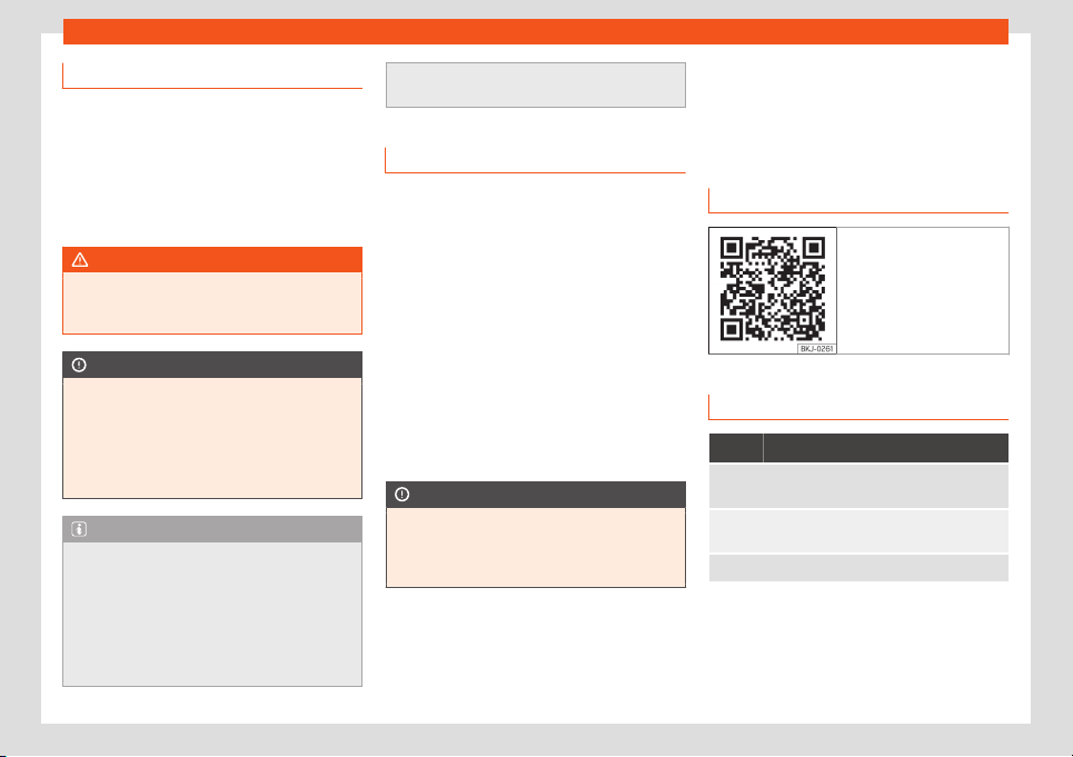
Driving
Driving on flooded roads
To prevent damage to the vehicle driving on
flooded roads, take the follo
wing into ac-
count:
●
The water should never come above the
lower edge of the bodywork.
●
Drive at pedestrian speed.
WARNING
After driving through flooded zones, brak-
ing effectiveness can decrease if the brake
discs or pads are damp
›
››
page 298.
CAUTION
●
Driving through flooded areas may dam-
age vehicle components such as the en-
gine, tr
ansmission or electrical system.
●
Whenever driving through water, the
Start-Stop system* must be switched off
›››
page 250.
Note
●
Check the depth of the water before en-
tering the flooded z
one.
●
Do not stop in the water, drive in reverse,
or stop the engine.
●
Vehicles travelling in the opposite direc-
tion cause waves that could exceed your
vehicle's critical height.
●
Avoid driving through salt water (corro-
sion)
››
›
page 376.
Trips abroad
●
With petrol vehicles, it should be ensured
that lead-free petrol is available thr
oughout
the journey
›››
page 343, Fuel types. Seek
information about service station networks
selling unleaded fuel.
●
In some countries, it is possible that your
vehicle is not sold and some spare parts may
not be availabl
e or the technical services
may only be able to make limited repairs.
SEAT importers and distributors will provide
information about the technical preparation
that your vehicle requires and also about
necessary maintenance and repair possibili-
ties.
CAUTION
SEAT does not accept liability for any dam-
age to the vehicle due to the use of a low
er
quality fuel, an inadequate service or the
non-availability of genuine spare parts.
Driver assistance systems
Cruise contr
ol syst
em
(CCS)*
R
el
at
ed video
Fig. 250 Dash panel
Control lamp
It lights up green
The Cruise Control System (GRA) is switched on and
active.
OR: The Adaptive Cruise Control system (CCS) is
s
witched on and active
.
OR: the speed limiter is switched on and active.
The control lamps light up when the ignition is
s
wit
ched on and shoul
d t
urn off aft
er appr
o
xi-
mately 2 seconds. This is the time taken for
the function check.
268
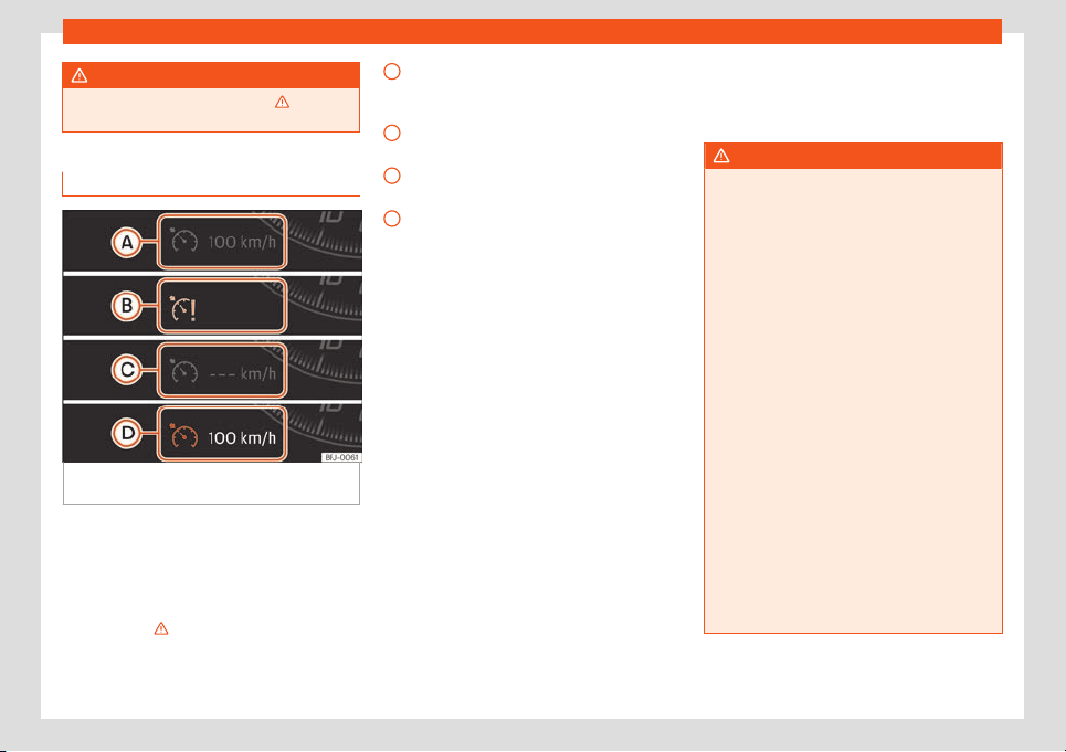
Driver assistance systems
WARNING
Observe the safety warnings
›››
in Con-
trol and warning lamps on page 81.
Introduction
Fig. 251
Instrument panel display: GRA status
indications.
The cruise control system (CCS) is able to
maint
ain the set speed fr
om 20 km/h (
15
mph).
The CSS only r
educes v
ehicl
e speed by
ceasing t
o accelerate, not by actively braking
the vehicle
›››
.
St
at
us displ
ay
GRA st
at
us
›
›
›
Fig. 251
CCS temporarily switched off. The set
speed is displayed in small or darkened
figures.
System error. Contact a specialised
workshop.
CCS switched on. The speed memory is
empty.
The CCS is switched on. The set speed is
displayed in large figures.
Changing gear in CCS mode
The CCS decelerates as soon as the clutch
pedal is pressed, intervening again automati-
cally after a gear is engaged.
Travelling down hills with the CCS
If the CCS cannot maintain a constant vehi-
cle speed downhill, brake and change down
a gear if necessary. The GRA is temporarily
disabled by pressing the brake.
Automatic off
The GRA disconnects automatically or is
temporarily interrupted:
●
If the system detects a fault that could af-
fect the working order of the CCS.
●
If you press and maintain the accelerator
pedal for a certain time, driving faster than
the stored speed.
●
If the dynamic driving control systems inter-
vene, ASR, ESC, etc.
A
B
C
D
●
If the br
ak
e pedal is pr
essed.
●
If the airbag is trigger
ed.
●
If the l
e
v
er is taken out of the D/S position.
WARNING
Use of GRA could cause accidents and se-
vere injuries if it is not possible to drive at a
constant speed maint
aining the safety dis-
tance.
●
Do not use GRA in heavy traffic, if the dis-
tance from the vehicle in front is insuffi-
cient, on steep roads, with several bends or
in slippery circumstances or on flooded
roads.
●
Never use the CCS when driving off-road
or on unpaved roads.
●
Adapt your speed and the distance to the
vehicles ahead in line with visibility, weath-
er, the condition of the road and the traffic
situation.
●
To avoid unexpected operation of the
cruise control system, turn it off every time
you finish using it.
●
It is dangerous to use a set speed which is
too high for other conditions.
●
If driving down a steep gradient, the GRA
cannot maintain a constant speed. The
speed can increase. In this case, brake and
change down a gear.
269
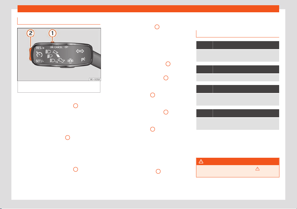
Driving
Operating the cruise control
Fig. 252
On the turn signal lever: controls for
oper
ating the GRA.
Connecting
●
Move the control
›
›
›
Fig. 252
1
to .
If no speed has been pr
ogr
ammed, the sys-
t
em will not contr
ol it.
Activ
ating the cruise contr
ol
●
Pr
ess button
›››
Fig. 252
2
in area
.
The curr
ent speed is st
or
ed and the cruise
contr
ol is activ
at
ed.
Temporarily interrupting
●
Move the control
›››
Fig. 252
1
to
or
st
ep on the br
ak
e
.
The cruise contr
ol system is switched off tem-
porarily. The speed is stored.
Reinstating the cruise control
●
Press button
›››
Fig. 252
2
in area
.
Cruise contr
ol is activ
at
ed at the st
or
ed
speed.
Adjusting the speed
Whil
e the GRA is set, the stored speed can be
adjusted with button
›››
Fig. 252
2
:
●
To increase in increments of 1 km/h (1 mph)
briefly pr
ess butt
on
›
›
›
Fig. 252
2
in the area
.
●
T
o incr
ease the speed without int
erruption,
k
eep button
›››
Fig. 252
2
pressed down in
the ar
ea
.
●
T
o r
educe in incr
ements of 1 km/h (1 mph)
briefly press button
›››
Fig. 252
2
in the area
.
●
To reduce the speed without interruption,
k
eep butt
on
›
›
›
Fig. 252
2
pressed down in
the ar
ea .
The v
ehicl
e adapts the curr
ent speed by ac-
cel
er
ating or st
opping accelerating. The vehi-
cle does not brake actively.
Switching off
●
Move control
›››
Fig. 252
1
to .
The syst
em is disconnect
ed and the memo-
rised speed is del
et
ed.
Speed limit
er
Contr
ol l
amp
It lights up grey
The speed limiter is switched on without program-
ming the speed
It lights up green
The speed limiter is switched on and active.
Flashes green
The speed set by the speed limiter has been excee-
ded.
It lights up
The adaptive cruise control (ACC) or the speed limit-
er is active.
The control lamps light up when the ignition is
s
wit
ched on and shoul
d t
urn off aft
er appr
o
xi-
mately 2 seconds. This is the time taken for
the function check.
WARNING
Observe the safety warnings
›››
in Con-
trol and warning lamps on page 81.
270
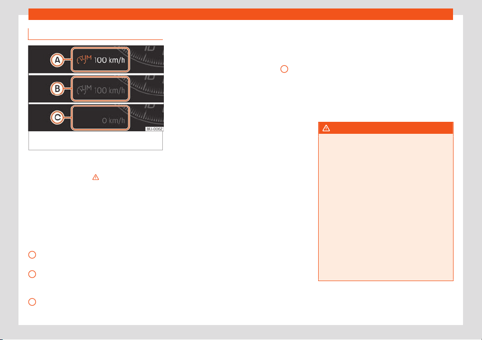
Driver assistance systems
Introduction
Fig. 253
On the instrument panel display: indi-
cations of the speed limit
ed st
at
us.
The speed limiter helps avoid exceeding a
pr
ogr
ammed speed, fr
om 30 km/h (
19 mph)
appr
o
x. and f
aster.
›››
Depending on the equipment, the speed limi-
t
ed can be oper
at
ed using the l
e
v
er of the
t
urn signals
›››
page 272 or by the third lever
›››
page 273.
Display messages on the speed limiter
Status
›››
Fig. 253:
The speed limiter is active. The last speed
set is displayed in large figures.
The speed limiter is not active. The last
speed set is displayed in small or dark-
ened figures.
The speed limiter is switched off. The total
mileage is displayed.
A
B
C
Switching between the speed limiter and
GRA or ACC (whil
e the speed limit
er is
connect
ed)
T
o change betw
een the driving assist
ance
syst
ems, press button
›››
Fig. 254
2
, then
sel
ect with the right thumb
wheel on the multi-
function st
eering wheel in the instrument
panel menu and pr
ess the thumb
wheel t
o
confirm your sel
ection.
It switches between the speed limiter and
cruise control (GRA) or the adaptive cruise
control (ACC).
Going down slopes with the speed limiter
If the programmed speed is exceeded while
driving downhill, after a short time the control
warning lamp
›››
page 270 flashes and
an audible warning may sound. Brake and
change down a gear.
Temporarily deactivate by pressing the
accelerator down
If the accelerator is pressed right down (kick-
down) and the set speed is exceeded be-
cause driver wishes to do so, the limiter is
temporarily disabled.
To confirm it being switched off an acoustic
signal sound once. While cruise control is off,
the control lamp flashes .
When the accelerator is no longer pressed
down and the speed is reduced below the set
value, the limiter switches on again. The con-
trol lamp lights up and remains lit.
Automatic off
The speed limiter is automatically switched
off:
●
If the system detects a fault that could neg-
atively affect the working order of the limiter.
●
If the airbag is triggered.
WARNING
After use, switch off the speed limiter to
prevent the speed being regulated without
it being r
equired.
●
The speed limiter does not relieve the
driver of their responsibility to drive at the
appropriate speed. Do not drive at high
speed if not necessary.
●
Using the speed limiter in adverse weath-
er conditions is dangerous and can cause
serious accidents. Use the speed limiter
only when the condition of the road surface
and the weather and traffic conditions al-
low it.
●
When driving on a steep gradient, the
speed limiter cannot limit the vehicle’s
speed. This can increase. In this case, brake
and change down a gear.
»
271
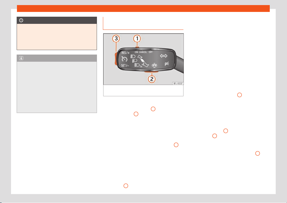
Driving
CAUTION
For automatic switching off due to system
failures, for security reasons, the limiter is
only compl
etely switched off when the
driver stops pressing the accelerator or
consciously switches it off.
Note
●
Different versions of the instrument panel
are availabl
e and therefore the versions
and instructions on the display may vary.
●
If the cruise control (GRA), the adaptive
cruise control (ACC) or the speed limiter
are connected when the ignition is switch-
ed off, the assistants will switch it when the
ignition is switched on, but only the speed
limiter will maintain the last programmed
speed.
Operating the speed limiter with
the t
urn signal l
e
v
er
Fig. 254
On the turn signal lever: buttons to
oper
at
e the speed limit
er
.
Connecting
●
Move control
›
›
›
Fig. 254
1
to position
and pr
ess butt
on
2
.
The l
ast pr
ogr
ammed speed is st
or
ed. It does
not t
ak
e effect yet.
Activating the speed limiter
●
While driving, press button
›››
Fig. 254
3
in
the ar
ea .
The curr
ent speed is st
or
ed as the maximum
speed.
Setting the pr
ogr
ammed speed
Y
ou can set the speed using button
›››
Fig. 254
3
:
●
Briefly pr
ess ar
ea
t
o increase speed in
small increments of 1 km/h (1 mph).
●
Press and hold the area to continu-
ously increase speed in increments of 10
km/h (5 mph).
●
Briefly press area to decrease speed
in small increments of 1 km/h (1 mph).
●
Press and hold area to continuously
decrease speed in increments of 10 km/h (5
mph).
The speed is limited to the set value.
Switching off the speed limiter
●
Move control
›››
Fig. 254
1
to position .
The syst
em s
wit
ches off
.
S
wit
ching off t
emporarily
If you want to temporarily deactivate the
speed limiter, e.g. for overtaking, move the
control
›››
Fig. 254
1
to position
or
pr
ess butt
on
2
.
Aft
er o
v
ert
aking, the speed limit
er can be ac-
tiv
at
ed with the previously programmed
speed by pressing button
›››
Fig. 254
3
in
the ar
ea
.
27
2
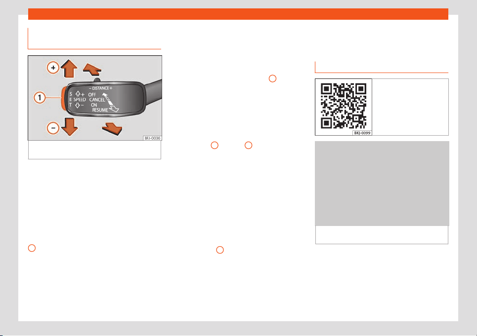
Driver assistance systems
Operating the speed limiter with
the thir
d l
e
v
er
Fig. 255
On the left of the steering column:
butt
ons t
o oper
at
e the speed limit
er
.
Connecting
●
Move the lever towards the steering wheel
t
o position .
The l
ast pr
ogr
ammed speed is st
or
ed. It does
not t
ake effect yet.
Activating the speed limiter
●
While driving, press button
›››
Fig. 255
1
.
The curr
ent speed is st
or
ed as the maximum
speed.
Setting the pr
ogr
ammed speed
The pr
ogr
ammed speed can be set:
●
Move the lever to the pressure point
to increase speed in small increments of 1
km/h (1 mph).
●
Move the lever upwards to increase in
increments of 10 km/h (5 mph).
●
Press the button
›››
Fig. 255
1
to re-
duce speed in small incr
ements of 1 km/h (
1
mph).
●
Mo
v
e the l
e
v
er downwards to reduce
in increments of 10 km/h (5 mph).
To change the programmed speed without
interruption, keep the lever pressed in the di-
rection
+
or
-
. The speed is
limit
ed t
o the set v
alue
.
S
wit
ching off the speed limit
er
●
Move the lever to position .
The system switches off.
Switching off temporarily
If you want to temporarily deactivate the
speed limiter, e.g. for overtaking, move the
lever to the pressure point or press but-
ton
›››
Fig. 255
2
.
Aft
er o
v
ert
aking, the speed limit
er can be ac-
tiv
at
ed with the previously programmed
speed by moving the lever to the pressure
point .
Emergency brake assistance
system (Front Assist)*
Introduction
Fig. 256 Related video
Fig. 257
On the instrument panel display: ad-
v
ance w
arning indications.
The objective of the system is to prevent
head-on collisions against ob
jects that may
be in the v
ehicl
e
’
s path or minimise the con-
sequences of such impacts.
Depending on se
v
eral factors and how criti-
cal the situation is, the system operates in a
staggered manner. First it warns the driver,
»
273
Driving
and if the driver’s reaction does not occur or
is insufficient, it activ
at
es independent emer
-
gency br
aking.
The function is int
ended t
o pr
event collisions
with parked vehicles or vehicles in the same
lane travelling in the same direction, or with
pedestrians crossing the vehicle’s path or cir-
culating on the same lane and in the same di-
rection. It may not activate in other hazard
situations
›››
.
Fr
ont Assist is activ
e betw
een 4 km/h (2.5
mph) and 250 km/h (
156 mph). Depending
on a r
ange of conditions, some of the func-
tions described bel
o
w are omitted to optimize
the behaviour of the system.
Front Assist is a driving assistance function
that can never replace the driver’s atten-
tion.
Safety distance warning
If the system detects that you are driving too
close to the vehicle in front, it will warn the
driver with this indication on the instrument
panel display .
The timing of the warning varies depending
on driver behaviour and the traffic situation.
Advance warning
If the system detects a possible collision with
the vehicle in front, it alerts the driver by
means of an audible warning and an indica-
tion on the instrument panel display
›››
Fig. 257.
The warning moment varies depending on
the traffic situation and driver behaviour. At
the same time, the vehicle will prepare for a
possible emergency braking
›››
.
Critical w
arning
If the driv
er f
ail
s t
o r
eact t
o the advance
warning, the system may actively intervene
in the brakes and generate a brief jolt to warn
the driver of the imminent danger of a colli-
sion.
Automatic braking
If the driver also fails to react to the critical
warning, the system may initiate independ-
ent emergency braking by progressively in-
creasing the braking in accordance with how
critical the situation is.
Driver emergency brake assistance sys-
tem
The system may detect that the driver is not
braking hard enough to avoid the collision. In
this case, it will increase the braking intensity.
The system cannot prevent a collision, al-
though it can significantly minimise the con-
sequences by reducing the speed and the
force of the impact.
WARNING
Observe the safety warnings
›››
in Con-
trol and warning lamps on page 81.
WARNING
Front Assist cannot change the laws of
physics or replace the driver in terms of
keeping control of the v
ehicle and reacting
to a possible emergency situation.
WARNING
Following a Front Assist emergency warn-
ing, pay immediate attention to the situa-
tion and try to avoid the collision as appli-
cabl
e.
●
If the Front Assist does not work as de-
scribed in this chapter (e.g. it repeatedly
intervenes unnecessarily), switch it off.
Have the system checked by a specialised
workshop. SEAT recommends visiting a
SEAT dealership.
●
Always adapt your speed and distance
away from the vehicle in front of you at all
times to suit visibility, weather, road and
traffic conditions.
●
The Front Assist alone cannot avoid acci-
dents and serious injuries.
●
In complex driving situations, Front Assist
may issue warnings and intervene in brak-
ing unnecessarily.
●
If the operation of the Front Assist is im-
paired by dirt or because the radar sensor
274
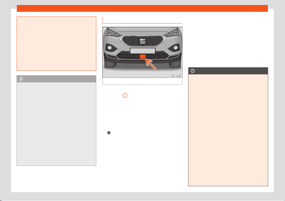
Driver assistance systems
has lost its settings, the system may issue
unnecessary warnings and intervene inop-
portunely in the braking.
●
The Fr
ont Assist does not react to animals
or vehicles crossing your path or ap-
proaching head-on down the same lane.
●
The Front Assist does not react to pedes-
trians walking head-on in the same lane.
●
The driver must always be ready to take
over the control of the vehicle.
Note
●
When Fr
ont Assist is connected, the indi-
cations of other functions on the screen
may be hidden.
●
When the Front Assist causes a braking,
the brak
e pedal is “harder”.
●
Automatic interventions by the Front As-
sist on the brakes may be interrupted by
pressing the clutch, accelerator or moving
the wheel.
●
The Front Assist may brake the vehicle
until it stops completely. However, the
brake system does not halt the vehicle per-
manently. Use the foot brake!
●
If the Front Assist does not work as de-
scribed in this chapter (e.g. in intervenes
several times unnecessarily), switch it off.
Radar sensors
Fig. 258
On the front bumper: radar sensors.
A radar sensor is fitted on the front bumper
›
›
›
Fig. 258
1
.
The r
adar sensor
's visibilit
y may be impair
ed
by dirt, or by envir
onment
al influences such
as r
ain or mist. In this case, the Front Assist
does not work. The instrument panel displays
the following message: Front Assist: No
sensor vision! Clean the radar sensor
›››
.
When the r
adar sensor begins t
o oper
at
e
pr
operly again, the Fr
ont Assist will be av
aila-
ble again. The message will disappear from
the screen.
Front Assist operation may be affected by a
strong radar reverse reflection. This may oc-
cur, for example, in a closed car park or due
to the presence of metallic objects (e.g.
guard rails or sheets used in road works).
The area in front of and around the radar
sensor should not be covered with adhesives,
additional or similar headlights, as this may
negatively affect Front Assist operation.
If the front of the vehicle is not properly re-
paired or structural modifications are made
to it, Front Assist operation may be affected.
SEAT recommends visiting a SEAT dealership
for this purpose.
CAUTION
If you have the feeling that the radar sensor
is damaged or has lost its settings, discon-
nect the Front Assist. This will avoid possi-
ble dangerous situations caused by the in-
adequat
e operation of the system. If this
occurs have it adjusted.
●
The sensor may not be adjusted correct-
ly if it receives an impact. This may com-
promise the system's efficacy or discon-
nect it.
●
Repairs to the radar sensor require spe-
cialist knowledge and special tools. SEAT
recommends visiting a SEAT dealership for
this purpose.
●
A registration plate or plate holder on the
front that is larger than the space for the
registration plate, or a registration plate
that is curved or warped can cause the ra-
dar to malfunction.
●
Clean away the snow with a brush and
the ice preferably with a solvent-free de-
icer spray.
275
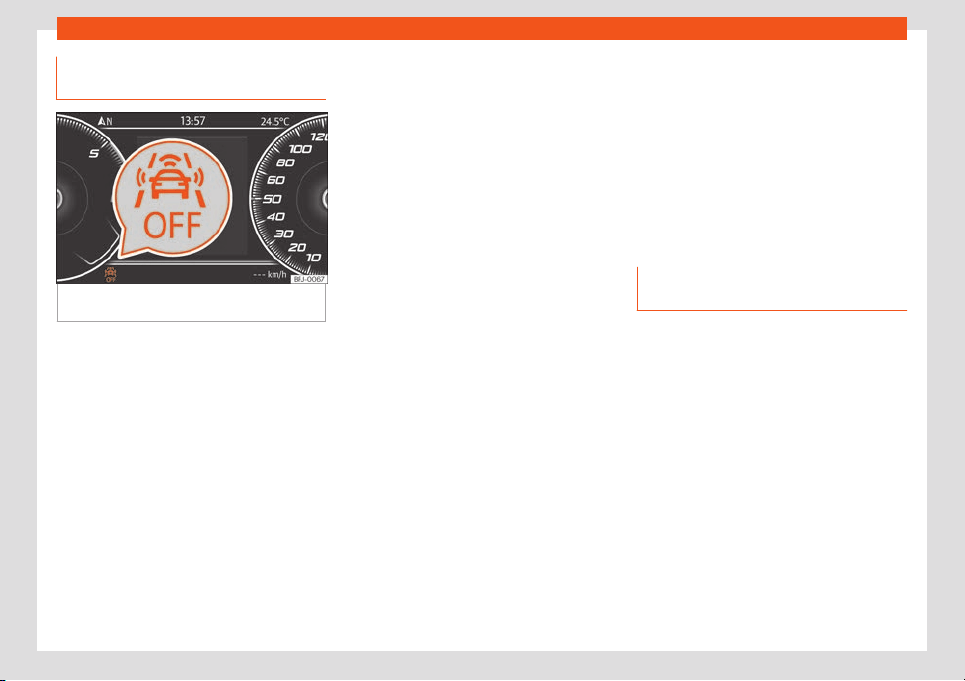
Driving
Operation of the emergency brake
assist
ance syst
em (Fr
ont Assist)
Fig. 259
On the instrument panel display:
Fr
ont Assist deactiv
at
ed indication.
The Front Assist is active whenever the igni-
tion is s
wit
ched on.
When the Fr
ont Assist is s
wit
ched off
, so t
oo
are the advance warning and the distance
warning functions.
SEAT recommends leaving the Front Assist
activated. Exceptions
›››
page 276, Deacti-
vating Front Assist temporarily in the fol-
lowing situations.
Switching the Front Assist on and off
With the ignition switched on, the Front Assist
can be deactivated or activated as follows:
●
Select the corresponding menu option us-
ing the button for the driver assistance sys-
tems
›››
page 79.
●
OR: using the Easy Connect system with
the button > SETTINGS > Driver as-
sistance
›››
page 82.
When the Front Assist is deactivated, the indi-
cation
›››
Fig. 259 will be shown on the in-
strument panel.
Activating or deactivating the pre-warning
(advance warning)
The advance warning can be activated or
deactivated in the Easy Connect system us-
ing button > SETTINGS > Driver as-
sistance
›››
page 82.
The system will store the setting for the next
time the ignition is switched on.
SEAT recommends keeping advance warning
active.
Depending on the vehicle’s infotainment sys-
tem the advance warning function may be
adapted in the following modes:
●
Advance
●
Medium
●
Delayed
●
Deactivated
SEAT recommends driving with the function in
“Medium” mode.
Switching distance warning on and off
The distance warning can be activated or
deactivated in the Easy Connect system us-
ing button > SETTINGS > Driver as-
sistance
›››
page 82.
The system will store the setting for the next
time the ignition is switched on.
SEAT recommends keeping the distance
warning active.
Deactivating Front Assist tempora-
rily in the following situations
In the following situations the Front Assist
shoul
d be deactiv
at
ed due t
o the syst
em's
limit
ations:
●
When the v
ehicle is to be towed.
●
If the vehicle is on a test bed.
●
When the radar sensor is damaged.
●
If the radar sensor receives a violent im-
pact.
●
If it intervenes several times unnecessarily.
●
If the radar sensor is temporarily covered
by an accessory.
●
When the vehicle is going to be loaded onto
transportation.
276
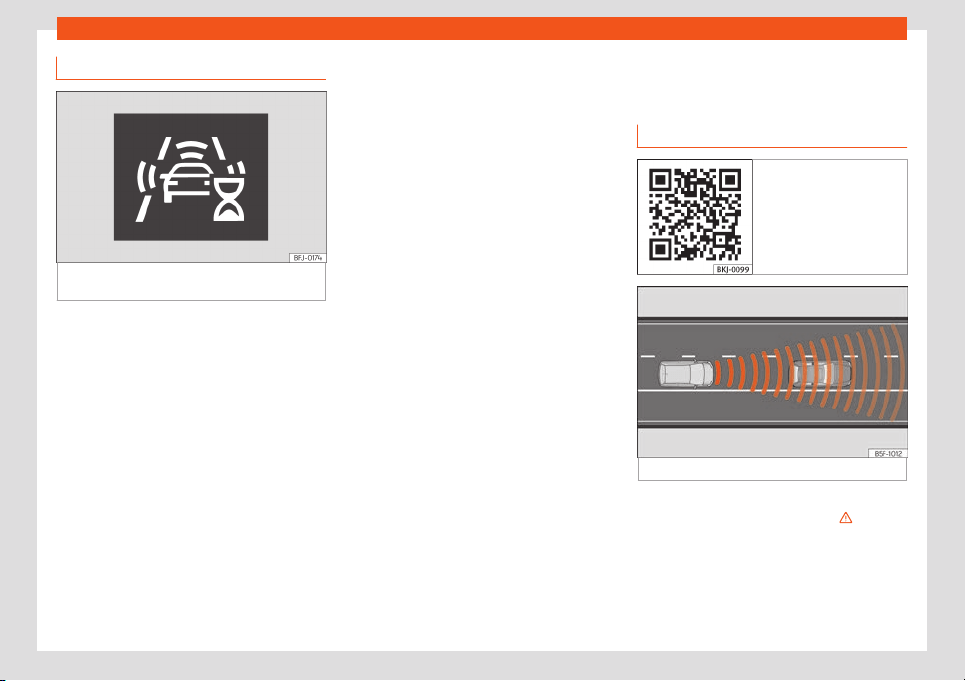
Driver assistance systems
System limitations
Fig. 260
On the instrument panel display: ini-
tial syst
em self
-calibr
ation indication.
Front Assist has certain limitations inherent to
the syst
em. Thus, in cert
ain cir
cumst
ances,
some of the r
eactions may be inappr
opriat
e
from the driver's standpoint. So pay attention
in order to intervene if necessary.
The following conditions may cause the
Front Assist not to react or to do so too
late:
●
In the first few instants of driving after
switching on the ignition, due to the system’s
initial auto-calibration. During this period, a
status icon
›››
Fig. 260is displayed.
●
If the Front Assist is switched off or dam-
aged.
●
If the radar sensor is dirty or covered.
●
On taking tight bends or complex paths.
●
Pressing the accelerator all the way down.
●
If the ASR has been disconnected or the
ESC activated in Sport mode
›››
page 304.
●
If the ESC is controlling.
●
If several brake lights of the vehicle or elec-
trically connected trailer are damaged.
●
If there are metal objects, e.g. guard rails or
sheets used in road works.
●
If the vehicle is reversing.
●
In case of snow or heavy rain.
●
In case of narrow vehicles, such as motor-
bikes.
●
Misaligned vehicles.
●
Vehicles crossing the other's path.
●
Vehicles approaching in the opposite direc-
tion.
●
Loads and accessories of other vehicles
that protrude over the sides, backwards or
over the top.
ACC - Adaptive Cruise Con-
trol*
Introduction
Fig. 261 Related video
Fig. 262
Detection area.
The ACC is an e
xt
ension of the v
ehicl
e
’
s
cruise contr
ol function (GRA)
›››
.
It all
o
ws the driv
er t
o set a cruise speed be-
tw
een 30 km/h (20 mph) and 2
10 km/h (
130
mph), and select the desired distance from
the previous in front.
»
277
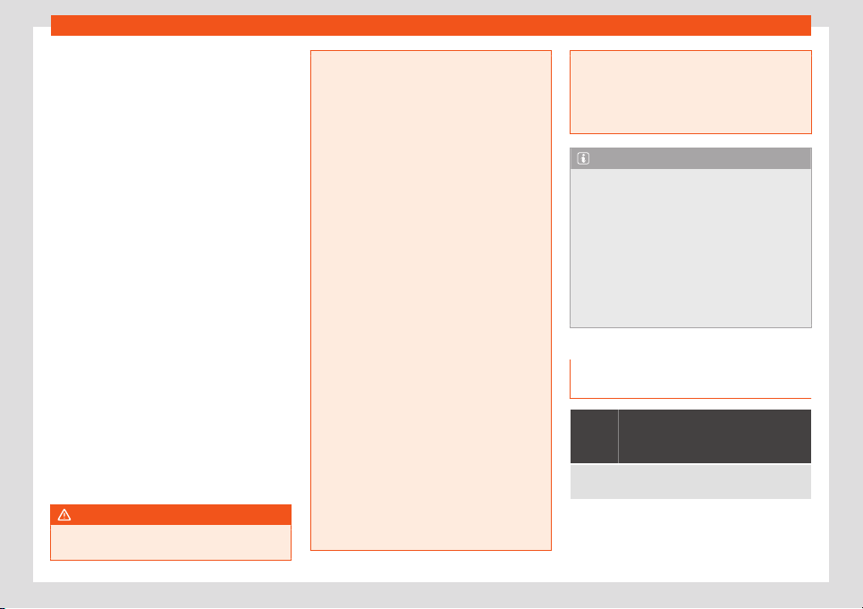
Driving
The ACC adapts the cruising speed of the
v
ehicl
e
, k
eeping a saf
e dist
ance aw
ay from
the vehicle in front, if there is one, depending
on speed.
When driving behind another vehicle, the
ACC reduces speed until it is the same as
that of the vehicle ahead and maintains the
set distance between the vehicles. If the vehi-
cle ahead accelerates, the ACC also accel-
erates the vehicle, going no higher than the
programmed target speed.
If the vehicle is equipped with automatic
gearbox, the ACC can brake the vehicle until
it stops completely if a vehicle in front of it
stops.
The distance programmed should be in-
creased when the road surface is wet.
Driver intervention prompt
ACC is subject to certain limitations inherent
to the system. In other words, in certain cir-
cumstances the driver will have to adjust the
speed and the distance from other vehicles.
In this case, the instrument panel screen will
warn you to intervene by applying the brake
and a warning tone will be heard
›››
page 278.
WARNING
The ACC’s technology cannot overcome
the system's inherent limitations or change
the laws of physics. If used negligently or
involuntarily, it may cause serious acci-
dents and injuries. The system is not a re-
placement for driv
er awareness.
●
Adapt your speed and safe distance to
the vehicle in front of you at all times to suit
visibility, weather, road and traffic condi-
tions.
●
Do not use ACC in poor visibility, or on
roads that are steep, with lots of curves or
slippery.
●
Never use ACC when driving off-road or
on unpaved roads. The ACC has been de-
signed for use on paved roads only.
●
ACC does not react when approaching a
fixed obstacle, such as the end of a traffic
jam, a damaged vehicle or a vehicle stop-
ped at the traffic lights.
●
The ACC only reacts to people if a pe-
destrian monitoring system is available.
The system does not react to animals or
vehicles crossing your path or approaching
head-on down the same lane.
●
If the ACC does not reduce speed suffi-
ciently, brake the vehicle immediately.
●
If you are driving with a spare wheel fit-
ted, the ACC system could automatically
switch off. Switch off the system when
starting off.
●
If the vehicle continues to move involun-
tarily after a driver intervention prompt,
brake the vehicle.
●
If the instrument panel screen displays a
driver intervention pr
ompt, adjust the dis-
tance.
●
The driver should be ready to accelerate
or brake at all times.
Note
●
If the ACC does not w
ork as described in
this chapter, do not use it until it has been
checked by a specialised workshop. SEAT
r
ecommends visiting a SEAT dealership for
this purpose.
●
Maximum speed with the ACC activated
is limited to 210 km/h (130 mph).
●
When the ACC is switched on, strange
noises may be heard during braking,
caused by the braking system.
Symbols on the instrument panel
displ
ay and contr
ol l
amps
The speed reduction by the ACC
to maintain the distance from the
vehicle in fr
ont is not sufficient.
Brake! apply the foot brake! Driver intervention
pr
ompt.
278
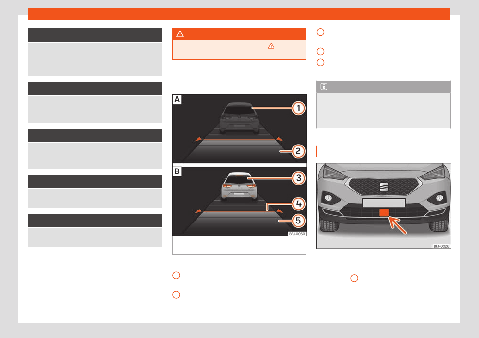
Driver assistance systems
ACC is not currently available.
While the vehicle is stationary, switch off the engine
and start it again. Perform a visual check of the radar
sensor
›››
Fig. 264. If it is still unavailable, refer to a
specialised workshop to have the system inspected.
Green symbol
The ACC is active.
A vehicle in front has been detected. The ACC ad-
justs speed and distance fr
om the vehicle in front.
Grey symbol
ACC is inactive (Standby).
A vehicle in front has been detected. The speed and
distance fr
om the vehicle in front are not adjusted.
Green symbol
The ACC is active.
No vehicle has been detected in front.
Grey symbol
ACC is inactive (Standby).
No vehicle has been detected in front.
Some control and warning lamps will light up
briefly when the ignition is s
wit
ched on t
o
check cert
ain functions. They will s
wit
ch off
aft
er a few seconds.
WARNING
Observe the safety warnings
›››
in Con-
trol and warning lamps on page 81.
Status display
Fig. 263
On the instrument panel display:
ACC inactiv
e (St
andby).
ACC activ
e
.
Indications on the display
›
›
›
Fig. 263
:
V
ehicl
e ahead det
ected. ACC is not ac-
tive and is not regulating your speed.
Distance from the vehicle ahead. ACC is
not active and is not regulating your dis-
tance.
1
2
Vehicle ahead detected. ACC is active
and is r
egul
ating your speed.
Dist
ance l
e
v
el 2 set by the driv
er.
ACC is active and is regulating your dis-
tance based on speed.
Note
When the ACC is connected, the indica-
tions on the instrument panel screen may
be concealed by warnings from other func-
tions, such as an incoming call.
Radar sensors
Fig. 264 On the front bumper: radar sensors.
A radar sensor is fitted on the front bumper
›
›
›
Fig. 264
1
.
The r
adar sensor
's visibilit
y may be impair
ed
by dirt, or by envir
onment
al influences such
as r
ain or mist. In this case the adaptive cruise
»
3
4
5
279
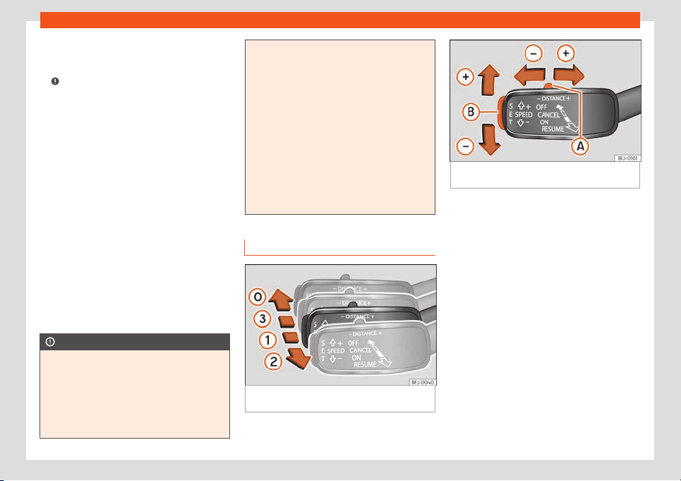
Driving
control (ACC) does not work. The instrument
panel displ
ays the f
oll
o
wing message:
ACC:
No sensor vision! Cl
ean the r
adar sensor
›››
.
When the r
adar sensor begins t
o oper
at
e
pr
operly, the ACC will become av
ail
able. The
message on the screen will switch off and the
ACC may be reactivated.
ACC operation may be affected by a strong
radar reverse reflection. This may occur, for
example, in a closed car park or due to the
presence of metallic objects (e.g. guard rails
or sheets used in road works).
The area in front of and around the radar
sensor should not be covered with adhesives,
additional or similar headlights, as this may
negatively affect ACC operation.
If the front of the vehicle is not properly re-
paired or structural modifications are made
to it, ACC operation may be affected. In this
scenario, SEAT recommends visiting a SEAT
dealership.
CAUTION
If you have the sensation that the radar
sensor is damaged or has lost its settings,
disconnect the ACC. This way you can
avoid possible damage. If this occurs have
it adjust
ed.
●
The sensor may not be adjusted correct-
ly if it receives an impact. This may com-
promise the system's efficacy or discon-
nect it.
●
Repairs to the radar sensor require spe-
cialist knowledge and special tools. SEAT
recommends visiting a SEAT dealership f
or
this purpose.
●
A registration plate or plate holder on the
front that is larger than the space for the
registration plate, or a registration plate
that is curved or warped can cause the ra-
dar to malfunction.
●
Clean away the snow with a brush and
the ice preferably with a solvent-free de-
icer spray.
ACC operation
Fig. 265
On the left of the steering column:
oper
ating the ACC with the thir
d l
e
v
er
.
Fig. 266 On the left of the steering column:
operating the ACC with the third lever.
When the ACC is connected, the green con-
tr
ol l
amp
will light up on the instrument
panel, and the pr
ogr
ammed speed and ACC
st
atus will be displayed
›››
Fig. 263.
What ACC settings are possible?
●
Connecting and activating the ACC
›››
page 281.
●
Setting your speed
›››
page 281.
●
Setting your distance
›››
page 281.
●
Disconnecting and deactivating the ACC
›››
page 281.
●
Adjusting the default distance level at the
start of your journey
›››
page 281.
●
Adjusting the driving profile
›››
page 281.
●
Conditions in which the ACC does not re-
act
›››
page 282.
280

Driver assistance systems
Connecting and activating the ACC
T
o connect and activ
at
e the ACC, the posi-
tion of the gearbo
x l
e
v
er, the vehicle speed
and the position of the third level of the ACC
must all be taken into account.
●
With manual transmission, the gear lever
must be in any gear except first. With auto-
matic transmission, the gear lever must be in
position D or S. Speed must be higher than
30 km/h (18 mph) approx.
●
To activate the ACC, move the third lever to
position
›››
Fig. 265
1
. At this time, the
ACC is not activ
e and ther
e is no pr
ogr
am-
med speed.
●
Ne
xt, pr
ess butt
on
›››
Fig. 266
B
or
mo
v
e the l
e
v
er t
o position
›››
Fig. 265
2
. At this moment the ACC is ac-
tiv
at
ed and the curr
ent speed and dist
ance
ar
e pr
ogr
ammed. The picture in the box will
change to Active mode
›››
Fig. 263 .
While ACC is active, the vehicle travels at a
set speed and distance from the vehicle
ahead. Both speed and distance can be
changed at any time.
Setting speed
●
To set the speed, move the third lever up
+
or down
–
to the desired speed
›
›
›
Fig. 263
6
. The speed adjustment is
made at 10 km/h (6 mph) int
erv
al
s.
●
If you wish t
o incr
ease speed by int
erv
als of
1 km/h (0.6 mph), move the lever to position
›››
Fig. 265
2
, or to decrease it press
butt
on
›
›
›
Fig. 266
B
.
The set speed can be changed when the v
e-
hicl
e is st
opped or during driving.
Setting your dist
ance l
e
v
el
●
To increase or reduce the distance, press
button
A
to the right or left
›
›
›
Fig. 266
.
The instrument panel displ
ay modifies the se-
l
ect
ed distance
›››
Fig. 263
4
. There are 5
dist
ance l
e
v
el
s t
o choose fr
om. SEAT recom-
mends level 3. The set distance can be
changed when the vehicle is stopped or while
driving
›››
.
Disconnecting and deactiv
ating the ACC
●
T
o disconnect the ACC mo
v
e the l
e
v
er to
position (fixed)
›››
Fig. 265
0
. An ACC de-
activated message appears and the func-
tion is t
ot
ally deactiv
at
ed.
If you do not wish t
o disconnect the ACC, just
t
o s
witch it temporarily to inactive mode
(Standby), move the third lever to position
3
or press the brake pedal.
It will al
so s
wit
ch t
o inactiv
e mode (St
andby)
if the v
ehicle is stopped and the driver door is
opened.
Adjusting the default distance level at the
start of your journey
In wet road conditions, you should always set
a larger distance with regard to the vehicle in
front than when driving in dry conditions
›››
.
In the Easy Connect syst
em, you can pr
e-se-
l
ect the dist
ance l
e
v
el when connecting the
ACC to: Very short, Short, Medium, Long and
Very long using button > SETTINGS >
Driver assistance
›››
page 82.
Changing the driving profile
In vehicles with SEAT Drive Profile, the driving
profile selected can have an influence on the
ACC’s acceleration and braking behaviour
›››
page 263.
In vehicles without SEAT Drive Profile, the be-
haviour of the ACC can also be affected if
any of the following drive profiles are selec-
ted in the Easy Connect system:
●
Normal
●
Sport
●
Eco
●
Convenience
In this case you must access the ACC set-
tings using button > SETTINGS > Driver
assistance > ACC
›››
page 82.
»
281

Driving
The following conditions may lead the
ACC not t
o r
eact:
●
If the accel
er
at
or is pr
essed.
●
If ther
e is no gear engaged.
●
If the ESC is controlling.
●
If the driver is not wearing his/her seat belt.
●
If several brake lights of the vehicle or elec-
trically connected trailer are damaged.
●
If the vehicle is reversing.
●
Driving faster than 210 km/h (130 mph).
Driver messages
ACC not available
●
The system cannot continue to guarantee
safe vehicle detection and is deactivated.
The sensor has lost its setting or is damaged.
Take the vehicle to a specialised workshop
and have the fault repaired.
ACC and Front Assist: currently
not available. No sensor vision
●
This message is displayed if the radar sen-
sor's visibility is impaired by leaves, snow,
dense fog or dirt. Clean the sensor
›››
Fig. 264.
ACC: currently not available.
Gradient too steep
●
The maximum road slope has been excee-
ded, hence safe ACC operation cannot be
guaranteed. The ACC cannot be switched
on.
ACC: only available in D, S or M
●
Select the D/S or M position on the selector
lever.
ACC: parking brake applied
●
The ACC is deactivated if the parking brake
is applied. The ACC is available once again
after the parking brake is released.
ACC: currently not available. In-
tervention of stability control
●
The indication is displayed when the elec-
tronic stability control (ESC) intervenes. In this
case, the ACC is automatically switched off.
ACC: Take action!
●
The indication is displayed if, when the ve-
hicle starts up on a hill with a slight slope, the
vehicle rolls back even although the ACC is
activated. Apply the brake to stop the vehicle
from moving/colliding with another vehicle.
ACC: speed limit
●
The indication is displayed in vehicles with
manual gearboxes if the current speed is too
low for the ACC mode. The speed limiter
switches off if the speed falls below 20 km/h
(12 mph).
ACC: available as of the 2nd gear
●
The ACC is operational as of the 2nd gear
(manual gearbox).
ACC: engine speed
●
This indication is displayed if, when the
ACC accelerates or brakes, the driver does
not shift up or down a gear in time, which
means exceeding or not reaching the permit-
ted RPM. The ACC switches itself off. A buzzer
warning is heard.
ACC: clutch applied
●
Vehicles with manual transmission: pressing
the clutch pedal for longer exits cruise con-
trol.
Door open
●
Vehicles with automatic transmission: the
ACC cannot be activated with the vehicle
stationary and the door open.
WARNING
There is a danger of rear collision when the
distance to the vehicle in front is reduced
and the speed diff
erence between both ve-
hicles is so great that a speed reduction by
the ACC is not sufficient. In this case, brake
immediately!
●
The ACC may not be able to detect all
situations properly.
●
Stepping on the accelerator may cause
the ACC not to intervene in braking. Driver
282
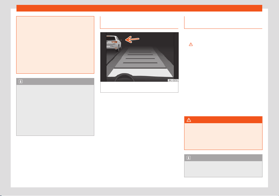
Driver assistance systems
braking will have priority over intervention
by the speed control or adaptive cruise
control.
●
Always be ready t
o use the brakes!
●
Observe country-specific provisions gov-
erning obligatory minimum distances be-
tween vehicles.
●
It is dangerous to activate control and re-
sume the programmed speed if the road,
traffic or weather conditions do not permit
this. Risk of accident!
Note
●
The programmed speed is erased once
the ignition or the ACC are switched off
.
●
When the traction control system (ASR) is
deactivated during acceleration or else the
ESC is activated in Sport* Mode
(
›››
page 82), the ACC switches off auto-
matically.
●
In vehicles with the Start-Stop system,
the engine switches off during the ACC
stopping phase and restarts for moving off.
Function to prevent overtaking on
the right
Fig. 267
On the instrument panel display:
ACC activ
e
, v
ehicl
e det
ect
ed in an out
er lane.
The ACC has a function to prevent overtaking
on the right.
If another v
ehicl
e is driving mor
e sl
o
wly t
o the
l
eft of the vehicle, it is shown on the display
›››
Fig. 267.
The system brakes the vehicle to avoid over-
taking on the right, and will avoid overtaking
based on speed. The driver can interrupt the
intervention of the ACC by pressing the ac-
celerator. At low speeds the function is inac-
tive, for greater comfort in a traffic jam or in
city traffic.
Deactivating the ACC temporarily
in certain situations
In the following situations the ACC should be
deactivated due to the system's limitations
››
›
:
●
When overtaking, on closed curves or
mountain roads, roundabouts, slip roads or
roadwork sections, pr
eventing the system
from accelerating to reach the programmed
speed.
●
When going through a tunnel, as operation
could be affected.
●
When other vehicles are going sl
ower in the
left lane. In this case, slower vehicles will be
overtaken on the right.
●
In case of heavy rain, snow or fog, the vehi-
cle in front may not be detected.
WARNING
If the ACC does not switch off in the situa-
tions described, serious accidents and inju-
ries may occur.
●
Always switch off the ACC in critical sit-
uations.
Note
If you do not switch off the ACC in the
aforementioned situations, you may com-
mit a legal offence.
283
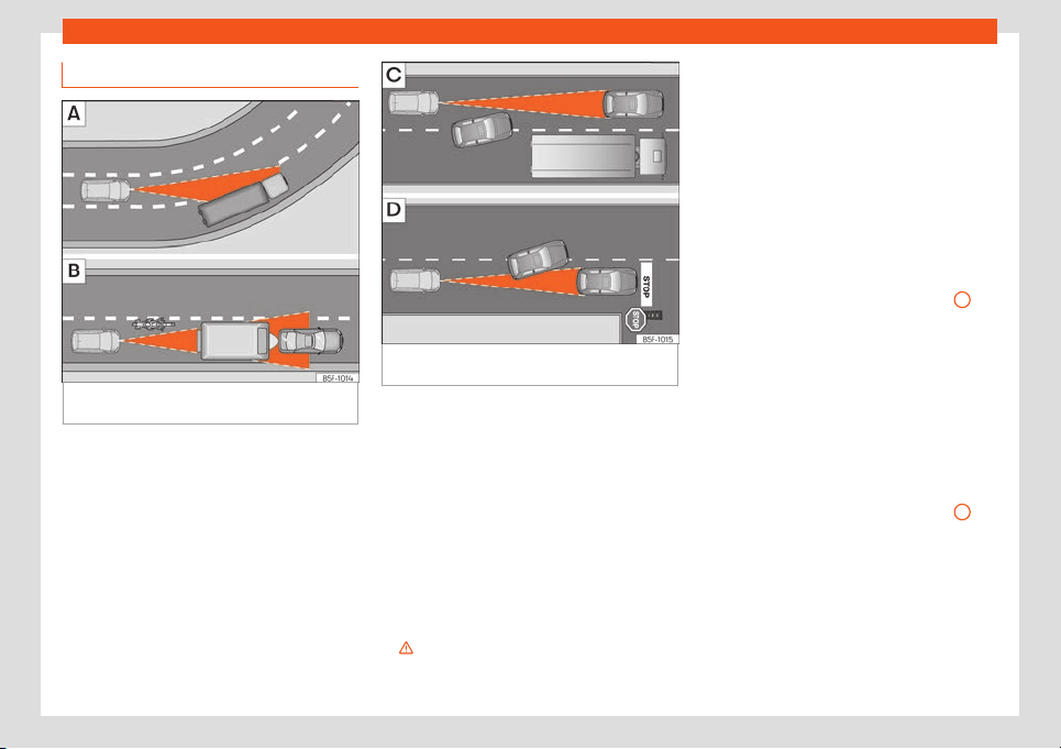
Driving
Special driving recommendations
Fig. 268
Vehicle on a bend.
Motorcyclist
ahead, out of range of the radar sensor
.
Fig. 269 Vehicle changing lanes. One
vehicle turning and another stationary.
The ACC has certain limitations inherent to
the syst
em. Cert
ain r
eactions, under cert
ain
cir
cumst
ances, may be une
xpected or come
late from the driver's point of view. So pay at-
tention in order to intervene if necessary.
The following situations require maximum at-
tention:
Starting driving after a stopping phase
(only with automatic transmission)
After a stopping phase, the ACC may begin
driving when the vehicle in front moves off
›››
.
Overtaking
When the t
urn signal lights up bef
or
e the v
e-
hicl
e st
arts t
o overtake, the ACC accelerates
the vehicle automatically and thus reduces
the distance from the vehicle in front.
When the vehicle moves to the overtaking
lane, if the ACC does not detect another ve-
hicle in front, it accelerates until it reaches the
programmed speed.
System acceleration can be interrupted at
any time by pressing the brake or moving the
third lever to position
›››
Fig. 265
3
.
Driving thr
ough a bend
When ent
ering or l
eaving some curv
es, the
r
adar sensor may cease t
o sense the v
ehicle
driving in front of it, or react to a vehicle in the
adjacent lane
›››
Fig. 268 . The vehicle may
brake unnecessarily or stop reacting to the
vehicle in front. In this case, the driver has to
intervene by accelerating or interrupting
braking by applying the brake or pushing the
third lever to position
›››
Fig. 265
3
.
Driving in t
unnel
s
When driving thr
ough t
unnel
s the r
adar sen-
sor may be limit
ed. Switch off the ACC in tun-
nels.
284
Driver assistance systems
Narrow or misaligned vehicles
The r
adar sensor can only det
ect narr
o
w v
e-
hicl
es or v
ehicles that circulate out of align-
ment when they enter its range
›››
Fig. 268 . In these cases, you should
brake as necessary.
Vehicles with special loads and accesso-
ries
Special loads and accessories of other vehi-
cles that jut out over the sides, backwards or
over the top may be out of the ACC's range.
SEAT recommends disconnecting it.
Other vehicles changing lanes
Vehicles changing lanes a short distance
away from your own can only be detected
when they are within range of the sensors. As
a consequence, the ACC will take longer to
react
›››
Fig. 269 . Brake yourself as neces-
sary.
Stationary vehicles
The ACC does not detect stationary objects
while driving, such as traffic tails or damaged
vehicles.
If a vehicle detected by the ACC turns or
moves over and there is a stationary vehicle
in front of it, the ACC will not react to it
›››
Fig. 269 . Brake yourself as necessary.
Vehicles driving in the opposite direction
and vehicles crossing your path
The ACC does not react to vehicles ap-
proaching from the opposite direction or ve-
hicles crossing your path.
Metal objects
Metal objects, e.g. guard rails or sheets used
in road works, can confuse the radar sensor
and cause the ACC to react wrongly.
Factors that may affect how the radar
sensor operates
If laser sensor operation is impaired, due to
heavy rain snow or mud, the ACC is deactiva-
ted temporarily. A message will be displayed
stating this. If necessary, clean the radar sen-
sor
›››
Fig. 264.
When the radar sensor begins to operate
properly, the ACC will become available. The
message will turn off and the ACC may be
reactivated.
ACC operation may be affected by a strong
radar reverse reflection, for example in a
closed car park. SEAT recommends discon-
necting it.
Trailer mode
When driving with trailer the ACC controls
less dynamically.
Overheated brakes
If the brakes overheat, for example on long
and steep descents, the ACC may be deacti-
vated temporarily. A message will be dis-
played stating this. In this case, adaptive
cruise control cannot be activated.
Cruise control may be reactivated once the
brake temperature has dropped. The mes-
sage will disappear. If the message ACC not
available remains on for quite a long time it
means that there is a fault. Contact a speci-
alised workshop. SEAT recommends visiting a
SEAT dealership.
WARNING
If you do not pay attention to the Press
the brake message, the vehicle may move
and crash int
o the vehicle ahead. Before
driving off again, check that the road is
clear. The radar sensor may not detect ob-
stacles on the road. This could cause an
accident and serious injuries. If necessary,
apply the brake.
285
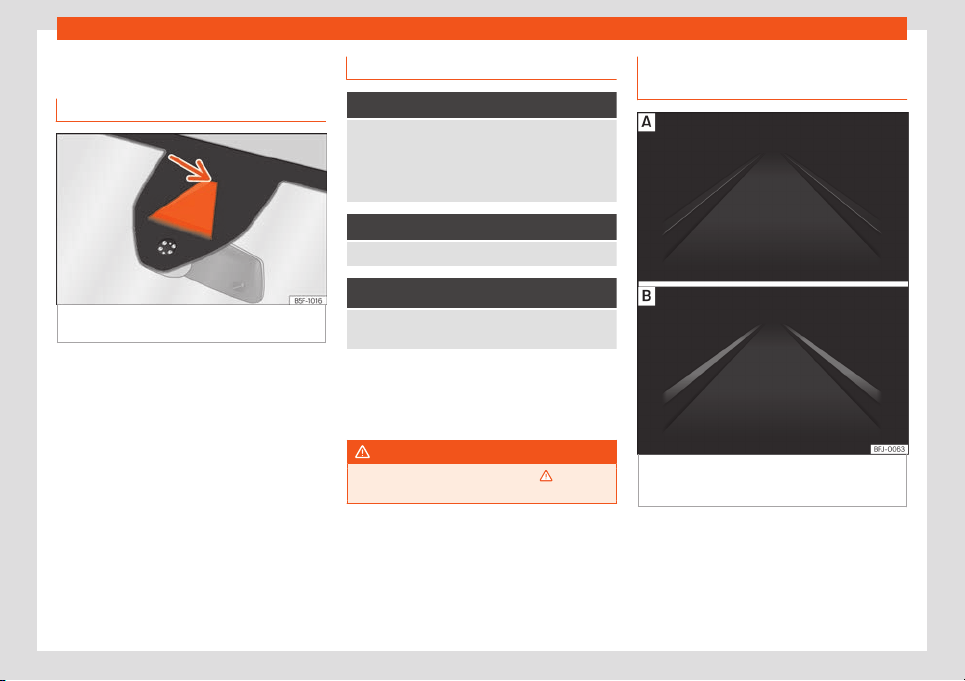
Driving
Lane Assist*
Intr
oduction
Fig. 270 On the windscreen: field of vision of
the L
ane Assist syst
em.
Using the camera located in the windscreen,
the L
ane Assist syst
em det
ects the possibl
e
lines dividing the l
anes. When the v
ehicl
e in-
voluntarily approaches a dividing line it has
detected, the system notifies the driver with a
corrective steering movement. The purpose is
not only to warn the driver, but also to keep
the vehicle inside the lane. This movement
can be over-regulated at any time.
No warning is produced with the turn signals
activated, given that the Lane Assist system
understands that a lane change is required.
As soon as the ignition is switched on, the
lane departure function is automatically acti-
vated.
Control lamp
It lights up yellow
Lane Assist system active but not available.
The system cannot accurately recognize the lane.
See page 287, The lane assist system is active
but it is not available (the control lamp is lit up
yellow).
It lights up green
Lane Assist system active and available.
It lights up yellow
Error in the lane departure warning system. Take the
vehicle to a specialised workshop to repair the f
ault.
Some control and warning lamps will light up
briefly when the ignition is s
wit
ched on t
o
check cert
ain functions. They will s
wit
ch off
aft
er a few seconds.
WARNING
Observe the safety warnings
›››
in Con-
trol and warning lamps on page 81.
Indications on the instrument panel
displ
ay
Fig. 271 On the instrument panel display: Indi-
cation on the L
ane Assist syst
em displ
ay (e
x-
ampl
e 1).
286
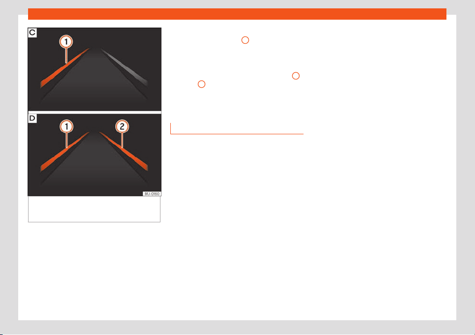
Driver assistance systems
Fig. 272
On the instrument panel display: Indi-
cation on the L
ane Assist syst
em displ
ay (e
x-
ampl
e 2).
Status display
Fig. 27
1
: The syst
em is activ
e
, but not
av
ailable, either because the minimum
speed has not been reached or because
the lane lines are not recognised.
Fig. 271 : The system is active and
available, both lane lines are recognised.
The steering angle is not being correc-
ted at this moment.
–
–
Fig. 272 : The system is operational,
the highlighted line
1
indicates that
ther
e w
as a risk of inv
olunt
arily cr
ossing
the l
ane line and that the st
eering is be-
ing adjusted to correct the angle.
Fig. 272 : The two highlighted lines
1
and
2
light up simultaneously when
both l
ane lines ar
e r
ecognised and the
L
ane Assist function is activ
at
ed.
Oper
ating mode
Switching the Lane Assist system on or off
●
Select the corresponding menu option us-
ing the butt
on f
or the driv
er assist
ance sys-
t
ems
›
›
›
page 79.
●
OR: by using the Easy Connect system with
button > SETTINGS > Driver assis-
tance
›››
page 82.
Lane Assist with lane centring guide
The Lane Centring Guide function is inten-
ded to keep the vehicle in the centre of the
lane.
If the driver has a tendency to veer slightly off
centre in the lane, the system adapts to driver
preferences.
●
The Lane Centring Guide function is ac-
tivated/deactivated in the Easy Connect sys-
–
–
tem using the button > SETTINGS
›››
page 82.
●
Or: By pressing and holding the Driving As-
sist button on the turn signal lever*
›››
page 79.
Automatic deactivation: the Lane Assist sys-
tem can be automatically deactivated if
there is a system malfunction. The control
lamp disappears.
Hands-Off Function
In the absence of steering wheel activity the
system alerts the driver with acoustic signals
and a text message on the dash panel asking
to actively take over the steering.
If the driver does not react to this, the system
also alerts the driver with a little shaking mo-
tion through the brakes and, if the vehicle has
it, activates the Emergency Assist function
›››
page 290.
In vehicles without Emergency Assist, the
adaptive lane guidance function will be disa-
bled after the corresponding warnings to the
driver.
The lane assist system is active but it is not
available (the control lamp is lit up yellow)
●
When driving at speeds below 65 km/h (38
mph).
●
When the Lane Assist system does not de-
tect the dividing lines of the road. For
»
287

Driving
example, in the event warnings indicating
r
oad w
orks, and sno
w
, dirt, moist
ur
e or r
eflec-
tions.
●
When the radius of a curve is too small.
●
When no road markings can be seen.
●
When the distance to the next marking to
too great.
●
When the system does not detect any clear
and active steering movement during a long
period of time.
●
Temporarily, in the event of very dynamic
driving styles.
●
If a turn signal is activated.
●
With the stability control system (ESC) in
Sport mode or switched off.
BSD Plus (Lane Assist with Blind Spot As-
sist)*
The BSD Plus function is achieved by activat-
ing the Lane Assist and BSD functions
›››
page 291. In this case, the Lane Assist
function expands its functions in the following
way:
If the driver tries to change lane and there is a
vehicle in the blind spot:
●
The lamp flashes in the corresponding
rear-view mirror even though the turn signal
has not been activated.
●
The steering wheel vibrates to warn the
driver of the risk of collision. This function can
be activated/deactivated in the Easy Con-
nect system with the button > SETTINGS
> Driver assistance > Lane Assist
›››
page 82.
●
torque is applied to correct the steering
and return the vehicle to its lane.
Switching off the Lane Assist system in the
following situations
Due to the limits of the Lane Assist system,
switch it off in the following situations:
●
When more attention is required of the driv-
er
●
When driving in a sporty style
●
In unfavourable weather conditions
●
On roads in poor condition
●
In areas of road works
WARNING
The intelligent technology in the Lane As-
sist system cannot change the limits im-
posed by the laws of physics and by the
very nature of the system. Car
eless or un-
controlled use of the Lane Assist system
may cause accidents and injury. The sys-
tem is not a replacement for driver aware-
ness.
●
Always adapt your speed and the dis-
tance to the vehicles ahead in line with visi-
bility, weather conditions, the condition of
the road and the traffic situation.
●
Always keep your hands on the steering
wheel so it can be turned at any time.
●
The L
ane Assist system does not detect
all road markings. The road surfaces, road
structures or objects in poor condition can
be incorrectly detected as road markings
under certain circumstances by the Lane
Assist system. In such situations, switch the
Lane Assist system off immediately.
●
Please observe the indications on the in-
strument panel and act as is necessary.
●
Always pay attention to the vehicle's sur-
roundings.
●
When the area of vision of the camera
becomes dirty, covered or is damaged, the
Lane Assist system function can be affec-
ted.
CAUTION
In order to avoid influencing the operation
of the system, the following points must be
taken int
o account:
●
Regularly clean the area of vision of the
camera and keep it in a clean state, without
snow or ice
›››
Fig. 270.
●
Do not cover the area of vision of the
camera.
●
Check that the area of vision of the wind-
screen camera is not damaged.
288
Driver assistance systems
Note
●
The lane departure warning system has
been e
xclusively developed for driving on
paved roads only.
●
If the Lane Assist system does not work as
described in this chapter, do not use it and
contact a specialised workshop.
●
If there is a fault in the system, have it
checked by a specialised workshop.
Traffic Jam Assist
Description and oper
ation
Traffic Jam Assist helps the driver keep the
car within its l
ane and t
o mo
v
e in conv
oy in
case of tr
affic congestion or sl
ow traffic.
Traffic Jam Assist is an additional function of
Lane Assist
›››
page 286 and combines Lane
Assist functions with Adaptive Cruise Control
(ACC)
›››
page 277. Therefore, it is essential
that you read these two chapters carefully
and note the limitations of the systems and
the information about them.
Operation of Traffic Jam Assist
At speeds of below 60 km/h (40 mph), Traffic
Jam Assist can maintain a (temporary) dis-
tance preset by the driver with respect to the
vehicle ahead and help stay within the lane
›››
.
T
o do this, the syst
em aut
omatically contr
ol
s
the accel
er
ator, brakes and steering, and
slows the vehicle, stopping it fully if neces-
sary, when faced with a vehicle in front that
has stopped. It automatically moves off again
when the vehicle ahead moves.
Traffic Jam Assist is designed only for use on
motorways and wide roads. Therefore, never
use it in city traffic.
Technical requirements for using Traffic
Jam Assist
●
Lane assist must be activated: button >
SETTINGS > Driver assistance > Lane
assist system
›››
page 82.
●
Adaptive lane guidance must be activated:
Infotainment button > SETTINGS > Driv-
er assistance > Lane Assist function
button, or: pressing and holding button Driv-
ing assistance
›››
page 79.
●
Adaptive Cruise Control (ACC) must be
connected and active
›››
page 280.
●
The speed must be below 60 km/h
(38 mph).
Traffic Jam Assist is not active (the Lane
Assist control light turns yellow)
●
If any of the conditions mentioned on
page 289, Technical requirements for us-
ing Traffic Jam Assist are no longer met.
●
If any of the conditions required for opera-
tion of the Lane Assist are not met
›››
page 286.
●
If any of the conditions necessary for the
adaptive cruise control (ACC) to work are no
longer fulfilled
›››
page 277.
Situations where traffic jam assist has to
be disconnected
Due to the limitations of the system, Traffic
Jam Assist must always be switched off in the
following situations:
●
When more attention is required by the
driver.
●
When driving in a very sporty style.
●
In adverse weather conditions, e.g. in case
of snow or heavy rain.
●
When driving on roads in poor condition.
●
In sections with roadworks.
●
In city journeys.
WARNING
The smart technology incorporated into
Traffic Jam Assist cannot defy the laws of
physics; it only works within the limits of the
»
289
Driving
system. Accidents and severe injury may
occur if Traffic Jam Assist is used negli-
gently or involuntarily. The system is not a
repl
acement for driver awareness.
●
Adapt your speed and safe distance to
the vehicle in front of you at all times to suit
the visibility, weather, road and traffic con-
ditions.
●
Do not use Traffic Jam Assist in city jour-
neys.
●
Do not use Traffic Jam Assist if there is
poor visibility, for example, in case of snow,
ice, rain or loose gravel, or on steep or slip-
pery sections or flooded roads.
●
Do not use Traffic Jam Assist offroad or
on roads where the surface is not firm. Traf-
fic Jam Assist has been designed for use on
paved roads only.
●
Traffic Jam Assist does not react to peo-
ple or animals or vehicles crossing your
path or that approach you head-on down
the same lane.
●
If Traffic Jam Assist does not reduce
speed sufficiently, brake the vehicle imme-
diately by applying the pedal.
●
If the vehicle continues to move when you
wish it to stop after a driver intervention
prompt, brake the vehicle by applying the
pedal.
●
If driver intervention is requested on the
dash panel display, immediately resume
control of the vehicle.
●
Keep your hands on the wheel at all times
to be ready to intervene in the st
eering at
any time. The driver is always responsible
for keeping the vehicle in its own lane.
●
Always be prepared to take charge of
driving (accelerating or braking) yourself.
Note
●
If T
raffic Jam Assist does not work as de-
scribed in this chapter, stop using it and
cont
act a specialised workshop.
●
If the system is faulty, take it to a special-
ised workshop and have it checked.
Emergency Assist
Description and oper
ation
Emergency Assist detects whether there is in-
activit
y by the driv
er and can aut
omatically
k
eep the car within the l
ane and st
op it alt
o-
gether if necessary. This way the system can
actively help avoid an accident.
Emergency Assist is an additional function of
Lane Assist
›››
page 286 and combines Lane
Assist functions with Adaptive Cruise Control
(ACC)
›››
page 277. Therefore, it is essential
that you read these two chapters carefully
and note the limitations of the systems and
the information about them.
Operation of Emergency Assist
Emergency Assist detects when the driver
ceases to perform any activity and repeated-
ly requests that he/she regain active control
of the vehicle, through the use of optical and
acoustic warnings and by applying the
brakes.
If the driver continues to do nothing, the sys-
tem automatically takes over the accelerator,
brakes and steering in order to brake the ve-
hicle and keep it in its lane
›››
. When the
emer
gency assist
ant is activ
ely r
egul
ating,
the haz
ar
d lights turn on
›››
page 115.
If the remaining braking distance is sufficient,
if necessary the system slows down the vehi-
cle until it stops completely and automati-
cally switches on the electronic parking
brake
›››
page 299.
Connecting and disconnecting Emergen-
cy Assist
The Emergency Assist is switched on auto-
matically when the Lane Assist is switched on
›››
page 286.
Technical requirements for using the Emer-
gency Assist
●
The adaptive cruise control (ACC) must be
switched on
›››
page 277.
●
The Lane Assist must be switched on
›››
page 286.
290
Driver assistance systems
●
The sel
ect
or l
e
v
er must be in the
D/S
posi-
tion or in the Tiptronic selector gate.
●
The system must have detected a lane
separation line on both sides of the vehicle
›››
Fig. 272.
The following conditions may cause the
Emergency Assist not to react or to switch
off automatically:
●
If the driver accelerates, brakes or moves
the steering wheel.
●
If any of the conditions mentioned in
›››
page 290, Technical requirements for
using the Emergency Assist are not fulfilled.
●
If any of the conditions required for opera-
tion of the Lane Assist are not met
›››
page 286.
●
If any of the conditions necessary for the
adaptive cruise control (ACC) to work are no
longer fulfilled
›››
page 277.
WARNING
The smart technology incorporated into
the Emergency Assist cannot overcome the
limits imposed by the laws of physics; it on-
ly works within the limits of the syst
em. The
driver is responsible for driving the vehicle.
●
Adapt your speed and safe distance to
the vehicle in front of you at all times to suit
the visibility, weather, road and traffic con-
ditions.
●
Keep your hands on the wheel at all times
to be ready to intervene in the st
eering at
any time.
●
The Emergency Assist alone cannot al-
ways avoid accidents or serious injuries.
●
If the operation of the Emergency Assist
is impaired, for example if the radar sensor
of the adaptive cruise control (ACC) or the
Lane Assist camera are covered or have
lost their settings, the system may inter-
vene inopportunely in braking or in steer-
ing.
●
The Emergency Assist does not react to
people or animal or vehicles crossing your
path or which approach you head-on in the
same lane.
WARNING
If the Emergency Assist Intervenes inoppor-
tunely, serious accidents and injuries may
occur.
●
If the Emergency Assist does not operate
properly, s
witch off the Lane Assist
›››
page 286. Doing so will also switch off
the Emergency Assist.
●
Have the system checked by a special-
ised workshop. SEAT recommends visiting a
SEAT dealership for this.
Note
●
Automatic interventions by the Emergen-
cy Assist on the brakes may be int
errupted
by pressing the accelerator or brake or by
moving the wheel.
●
Hazard warning lights that come on auto-
matically can be swit
ched off by pressing
the accelerator or the break, moving the
steering wheel or pressing the hazard
warning light switch.
●
If this occurs, the Emergency Assist may
decelerate the vehicle until it comes to a
complete stop.
●
When the Emergency Assist is activated,
it is only available again after the ignition
has been switched off and back on again.
Using the blind spot detector
(BSD) with parking assist
ant
(RC
T
A)*
Intr
oduction
The blind spot detector (BSD) helps to detect
the tr
affic sit
uation behind the v
ehicl
e
.
The int
egr
ated parking assistant (RCTA) helps
the driver when backing out of a parallel
parking spot and in manoeuvring.
The blind spot detector has been developed
for driving on paved roads.
»
291
Driving
WARNING
The smart technology incorporated into
the blind spot detector (BSD) with parking
assistance (RCTA) included cannot ov
er-
come the limits imposed by the laws of
physics; it only works within the limits of the
system. Accidents and severe injury may
occur if the blind spot detection system or
the rear cross traffic alert are used negli-
gently or involuntarily. The system is not a
replacement for driver awareness.
●
Adapt your speed and safe distance to
the vehicle in front of you at all times to suit
visibility, weather, road and traffic condi-
tions.
●
Keep your hands on the wheel at all times
to be ready to intervene in the steering at
any time.
●
Pay attention to the control lamps that
may come on in the external rear view mir-
rors and on the instrument panel, and fol-
low any instructions they may give.
●
The blind spot assistant could react to
any special constructions that might be
present on the sides of the vehicle: e.g. high
or irregular dividers. This may cause erro-
neous warnings.
●
Never use the blind spot detector with
rear cross traffic alert on unpaved roads.
The blind spot detector with rear cross traf-
fic alert has been designed for use on
paved roads.
●
Always pay attention to the vehicle's sur
-
roundings.
●
Never use the blind spot detector or the
parking assistant if the radar sensors are
dirty.
●
The external rear view mirror control
lamps may have limited functionality due
to solar radiation.
CAUTION
●
The r
adar sensors on the rear bumper
may be damaged or shifted in the event of
a collision, for e
xample, when entering or
exiting a parking space. This may result in
the system disconnecting itself, or at least
possibly having its functionality diminished.
●
In order to ensure that the radar sensors
work properly, keep the rear bumper free of
snow and ice and do not cover it.
●
The rear bumper should only be painted
with paint authorised by SEAT. The blind
spot detector's functions may be limited or
work incorrectly if other paints are used.
Note
If the blind spot detector with parking as-
sistant does not work as described in this
chapter, stop using it and contact a speci-
alised w
orkshop.
Control lamps
Control lamp in external rear view mirrors:
It lights up
It lights up once briefly: the blind spot detector is ac-
tivated and ready to operate.
It lights up: blind spot detector has detected a vehi-
cle in the blind spot.
Flashes
The blind spot detector has detected a vehicle in the
blind spot and the turn signal has been turned on in
the direction of the detected vehicl
e
›››
.
For vehicles that are also equipped with Lane Assist
›››
page 286, a warning to s
witch lanes will also ap-
pear even though the turn signal has not been en-
gaged (blind spot detector “Plus”).
The control lamps light up when the ignition is
s
wit
ched on and shoul
d t
urn off aft
er appr
o
xi-
mately 2 seconds. This is the time taken for
the function check.
If there are no indications from the control
lamp in the external rear view mirror, this
means that the blind spot detector has not
detected any other vehicles in the area
›››
.
If the dipped beam is on, then the contr
ol
l
amps in the e
xt
ernal r
ear vie
w mirr
ors will be
dimmed (night mode).
292
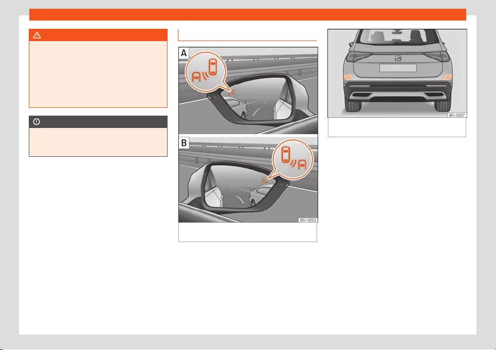
Driver assistance systems
WARNING
If the warning lamps and the corresponding
messages are ignored when they light up,
the vehicle may stall in tr
affic and cause
accidents and severe injuries.
●
Never ignore the warning lamps or mes-
sages.
●
Carry out the necessary operations.
CAUTION
Failure to heed the control lamps and cor-
responding text messages when they light
up may result in damage to the vehicl
e.
Blind spot detector (BSD)
Fig. 273
In the exterior mirrors: blind spot de-
t
ect
or indication.
Fig. 274 Rear view of the vehicle: radar sensor
zones.
The blind spot detector uses radar sensors to
monit
or the ar
eas behind the v
ehicl
e
›
›
›
Fig. 274. The system does this by measur-
ing the vehicle's distance from other vehicles
and its speed differential. The blind spot de-
tector will not work at speeds of less than ap-
prox. 15 km/h (9 mph). The system uses opti-
cal signals in the external rear view mirrors to
notify the driver.
Indication on the exterior mirror
The control lamp (expanded view) provides
an indication in the corresponding external
mirror
›››
Fig. 273 regarding the traffic situa-
tion behind the vehicle, if it is deemed to be
critical. The control lamp of the left-hand ex-
ternal mirror indicates the traffic situation to
the left of the vehicle, and the control lamp of
the right-hand external mirror indicates the
traffic situation to the right of the vehicle.
»
293

Driving
In the case of retrofitted tinted windows or
windo
ws with tint
ed film, the indications of the
e
xt
ernal mirr
ors may not be seen cl
early or
corr
ectly.
Keep the external mirrors clean and free of
snow and ice, and do not cover them with ad-
hesives or other similar materials.
Radar sensors
The radar sensors are located on the left and
right of the bumper and are not visible from
the outside
›››
Fig. 274. The sensors monitor
both the blind spot and traffic behind the ve-
hicle
›››
Fig. 275,
›››
Fig. 276. The range to the
sides of the vehicle is a bit larger than the
width of a lane.
The lane width is not detected individually,
but is rather pre-configured in the system.
Thus if you are driving in wide lanes or in be-
tween two lanes, the indications may be in-
correct. Furthermore, the system can detect
vehicles driving in the lane next to you (if
there are any), and can also detect station-
ary objects such as dividers, and thus give an
incorrect indication.
294
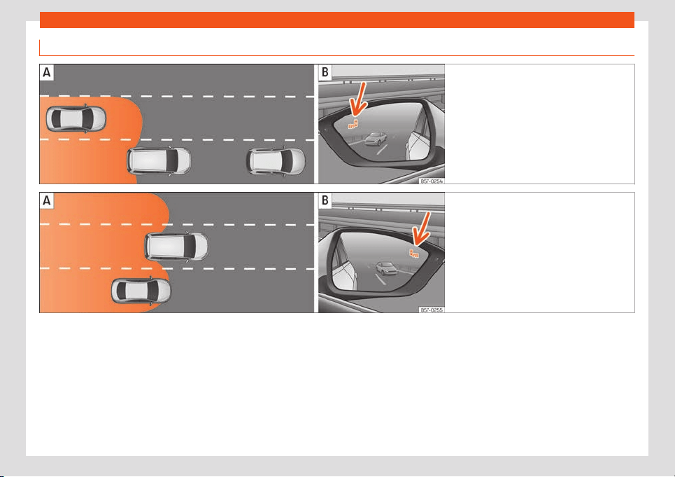
Driver assistance systems
Driving situations
Fig. 275 Schematic representation: Passing
situation with traffic behind the vehicle.
Indi-
cation from the blind spot detector in the left-
hand external mirror.
Fig. 276 Schematic representation: Situa-
tion of passing and then moving into the right-
hand lane.
Indication from the blind spot de-
tector in the right-hand external mirror.
In the following situations, an indication will
be displ
ayed in the e
xt
ernal mirr
or
›
›
›
Fig. 275
(arrow) or
›››
Fig. 276 (arrow):
●
When being overtaken by another vehicle
›››
Fig. 275 .
●
When passing another vehicle
›››
Fig. 276
with a speed differential of approx. 10 km/h
(6 mph). If the vehicle is passing at a consid-
erably higher speed, no indication will be dis-
played.
The faster the vehicle approaches, the soon-
er an indication will be displayed in the exter-
nal mirror, because the blind spot detector
takes into account the speed differential with
other vehicles. Thus even though the distance
from the other vehicle is identical, the indica-
tion will appear sooner in some cases and
later in others.
Physical limitations inherent to the system
In some situations the blind spot detector
may not interpret the traffic situation correct-
ly. E.g. in the following situations:
●
on tight bends;
●
in the case of lanes with different widths;
●
at the top of slopes;
●
in adverse weather conditions;
»
295
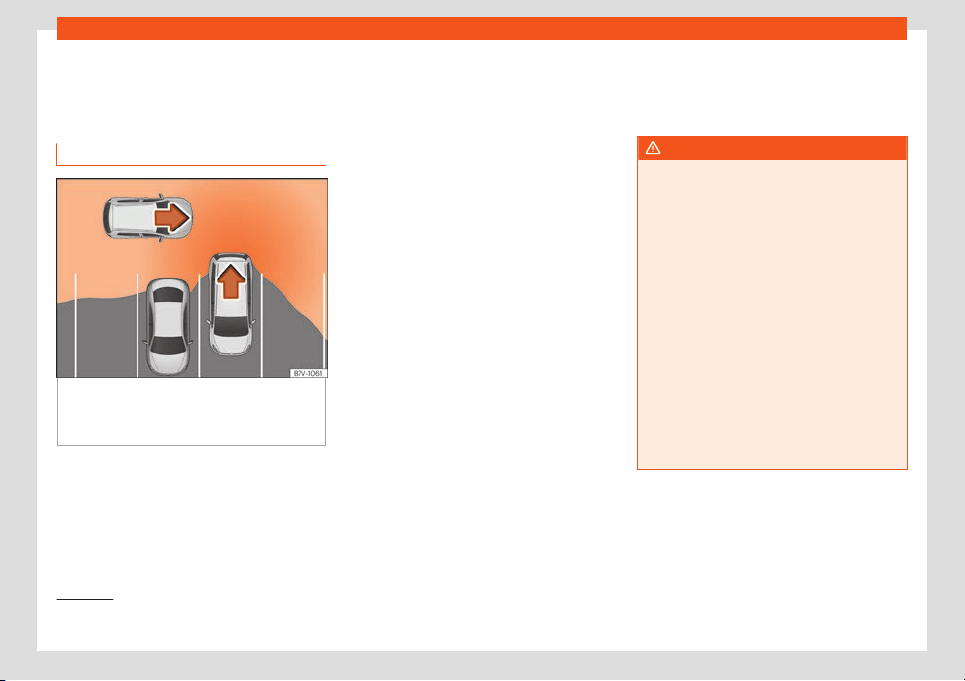
Driving
●
in the case of special constructions t
o the
side of the v
ehicl
e
, e
.g., high or irr
egul
ar divid-
ers.
Rear cross traffic alert (RCTA)
Fig. 277
Schematic representation of the rear
cr
oss tr
affic al
ert assist
ant: z
one monit
or
ed
around the vehicle while leaving a parking
space.
The parking assistant uses the radar sensors
on the r
ear bumper
›
›
›
Fig. 27
4
t
o monitor the
traffic crossing behind the vehicle as it backs
out of a parallel parking space or as it is be-
ing manoeuvred, for example in very low visi-
bility conditions.
If the system detects that someone else on
the road is approaching the rear of the vehi-
cle
›››
Fig. 277, an acoustic alarm is heard.
In addition to the acoustic alarm, the driver is
also informed by means of a visual signal on
infotainment system display. This signal is dis-
played in the form of a red strip at the back of
the image of the vehicle on the infotainment
system screen. This strip displays the side of
the vehicle towards which traffic is approach-
ing.
1)
Automatic braking to reduce damages
If the rear cross traffic alert detects that
someone else on the road is approaching the
rear of the vehicle and the driver does not
step on the brake, the system will engage the
brakes automatically.
The parking system helps the driver by auto-
matically engaging the brakes to reduce any
damage. The automatic intervention on the
brakes takes place when driving in reverse at
approx. 1-12 km/h (1-7 mph. After detecting
that the vehicle is stationary, the system
keeps it that way for around 2 seconds.
After automatically braking to reduce dam-
age, the system will not be able to automati-
cally brake again for approximately 10 sec-
onds.
You can interrupt the automatic braking by
stepping hard on the accelerator pedal or
the brake pedal in order to regain control of
the vehicle.
WARNING
The smart technology incorporated into
the rear cross traffic alert cannot ov
er-
come the limits imposed by the laws of
physics; it only works within the limits of the
system. The parking assistant function
should not tempt you into taking any risks.
The system is not a replacement for driver
awareness.
●
The system should never be used in limi-
ted visibility conditions or complicated
traffic, e.g., in high-traffic areas or when
crossing multiple lanes.
●
Be sure to always be aware of the vehi-
cle's surroundings, since the system often
fails to detect things such as bicycles or
pedestrians.
●
The rear cross traffic alert itself will not
brake the vehicle to a complete stop.
1)
It is only displayed if the vehicle is equipped
with a parking system.
296
Braking and parking
Using the blind spot detector (BSD)
with parking assist
ant (RC
T
A)
Activating and deactivating the blind spot
detector (BSD) with parking assistant
(RCTA)
The blind spot detect
or with parking assistant
can be switched on and off by accessing the
Assistance systems menu on the dash
panel display using the steering wheel con-
trols. If the vehicle is equipped with a multi-
function camera, it can also be accessed by
means of the driver assistance systems key
located on the main beam headlight lever.
Open the Assistants menu.
●
Blind spot
●
Exit Assist
If the verification box on the control panel is
checked , the functionalit
y will be automat-
ically activated at ignition.
When the blind spot detector is ready to op-
erate, the indications in the external mirrors
will turn on briefly as confirmation.
When the vehicle is restarted, the last adjust-
ment in the system will remain active.
If the blind spot detector was automatically
deactivated, it will only be possible to restart
the system after turning the vehicle off and
restarting it.
Automatic deactivation of the blind spot
detector (BSD)
The radar sensors of the blind spot detector
with rear cr
oss traffic alert will be automati-
cally deactivated when, among other rea-
sons, one of the sensors is detected to be
permanently covered. This may be the case
if, for example, there is a layer of snow or ice
in front of one of the sensors.
The relevant text message will appear in the
dash panel display.
Trailer mode
The Blind spot detector and the rear cross
traffic alert will be automatically deactivated
and it will be impossible to activate them if
the tow hitch is electrically connected to a
trailer or other similar object.
As soon as the driver starts to drive with a
trailer connected electrically to the vehicle, a
message will appear on the instrument panel
display indicating that the blind spot detector
and the rear cross traffic alert are deactiva-
ted. Once the trailer has been unhitched from
the vehicle, if you want to use the blind spot
detector and the rear cross traffic alert, you
will have to reactivate them in the corre-
sponding menu.
If the towing hitch is not factory equipped,
then the blind spot detector and the rear
cross traffic alert will have to be deactivated
manually when driving with a trailer.
Braking and parking
Br
aking syst
em
Contr
ol l
amps
It lights up red
Brake fluid level too low
›››
page 357 or fault in the
brake system.
Do not carry on driving!
It lights up red
Electronic parking brake
›››
page 299.
The warning lamp t
urns off when the handbrake is re-
leased.
It lights up green
Auto Hold function activated
›››
page 301.
It lights up yellow
Front brake pads worn.
Contact a specialised workshop immediately.
WARNING
●
If the brake warning lamp does not go
out or if it lights up when driving, the brak
e
fluid level in the reservoir is too lo so there
is a risk of an accident
›››
page 357, Brake
fluid. Stop the vehicle and do not drive on.
Obtain technical assistance.
»
297

Driving
●
If the brake warning lamp lights up to-
gether with the ABS l
amp this could be
due to an ABS fault. When this function
fails, the rear wheels can lock up. Under
certain circumstances, the rear of the vehi-
cle may skid, with the danger of losing con-
trol. Stop and seek technical assistance.
●
If the lamp lights up, alone or accom-
panied by a warning message on the in-
strument panel display, please go immedi-
ately to a specialised workshop to check
the brake pads and to replace them if they
are worn.
Information about the brakes
New brake pads
F
or the first 200 t
o 300 km (
100 t
o 200
mil
es), ne
w br
ake pads have not yet reached
their maximum braking capacity, and need to
be “run in” first. However, you can compen-
sate for the slightly reduced braking effect by
applying more pressure on the brake pedal.
Avoid overloading the brakes while running
them in.
Wear
The rate of wear on the brake pads depends
a great deal on how you drive and the condi-
tions in which the vehicle is operated. This is a
particular problem in urban traffic and short
stretches, or with very sporty driving.
Depending on the speed, the braking force
and the environmental conditions (e.g. tem-
perature, air humidity, etc.) noises may be
produced when braking.
Wet roads or road salt
In certain situations (for example, on driving
through flooded areas, in severe downpours
or after washing the vehicle) the braking ac-
tion could be delayed if the discs and pads
are damp, or frozen in winter. In this case the
brakes should be “dried” by pressing the
brake pedal several times.
At high speed and with the windscreen wipers
activated, the brake pads will briefly touch
the brake discs. This takes place, although
unnoticeable to the driver, at regular intervals
to improve the response time of the brakes
when they are wet.
The effectiveness of the brakes can also be
temporarily reduced if the vehicle is driven for
some distance without using the brakes when
there is a lot of salt on the road in winter. The
layer of salt that accumulates on the discs
and pads can be removed by gently apply-
ing the brakes a few times.
Corrosion
There may be a tendency for corrosion to
form on the discs and dirt to build up on the
brake pads if the vehicle is used infrequently
or the brakes are not used very often.
If the brakes are not used frequently, or if rust
has formed on the disks, it is advisable to
clean off the pads and disks by braking firmly
a few times at a moderately high speed
›››
.
F
ault in the br
ak
e syst
em
If the br
ak
e pedal tr
avel should ever increase
suddenly, this may mean that one of the two
brake circuits has failed. Drive immediately to
the nearest specialised workshop and have
the fault repaired. Drive there slowly and re-
member that you will have to apply more
pressure on the brake pedal and allow for
longer stopping distances.
Low brake fluid level
Malfunctions can occur in the brake system if
the brake fluid level is too low. The brake fluid
level is monitored electronically.
Brake servo
The brake servo increases the pressure you
apply to the brake pedal. It works only when
the engine is running.
WARNING
Any anomaly in the brake system can in-
crease the braking distance, with the re-
sulting risk of an accident.
●
New br
ake pads and discs must be run in
and do not have the correct friction during
the first 200 km (124 miles). This reduced
298
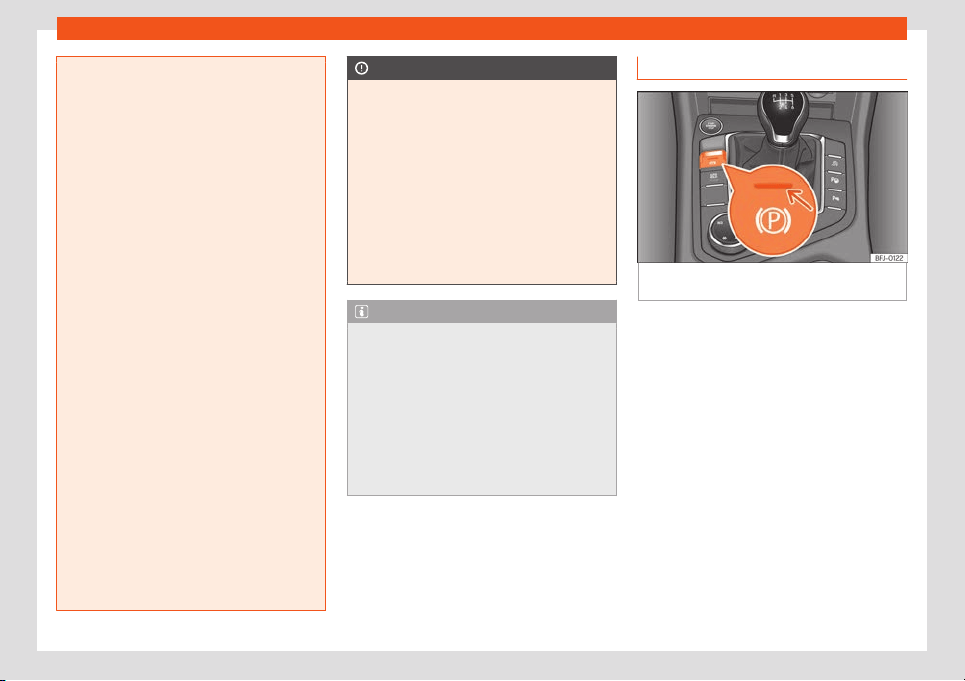
Braking and parking
braking capacity may be offset by pressing
on the brake pedal a little harder.
●
If you are driving on r
oads which have
been salted, braking effectiveness may be
decreased.
●
Brakes can overheat if used excessively
on slopes. Before driving down a long steep
slope, it is advisable to reduce speed and
change down into a lower gear or range.
Therefore, using the engine brake relieves
the brakes.
●
Gentle continuous braking causes the
brakes to overheat and the braking dis-
tance will increase. Apply and then release
the brakes alternately.
●
Apply the brakes heavily to clean the
brake system only in a suitable traffic situa-
tion. Do not put other road users in danger:
there is risk of causing an accident.
●
Ensure the vehicle does not move while in
neutral, when the engine is stopped. The
braking distance is increased considerably
when the brake servo is not active.
●
If the brake is subjected to high stresses,
vapour bubbles may form in the brake sys-
tem's pipes. This reduces the efficiency of
the brakes.
●
Non-standard or damaged front spoilers
could restrict the airflow to the brakes and
cause them to overheat. Before purchasing
accessories please read the relevant in-
structions.
CAUTION
●
Never let the brakes “drag” by l
eaving
your foot on the pedal when it is not neces-
sary to brake. This overheats the brakes, re-
sulting in longer stopping distances and
greater wear.
●
Before driving down a long, steep gradi-
ent, it is advisable to reduce speed and se-
lect a lower gear. This makes use of engine
braking and relieves the brakes. If you still
have to use the brakes, it is better to brake
firmly at intervals than to apply the brakes
continuously.
Note
●
If the brake servo is out of action, for ex-
ample when the car is being t
owed, you will
have to press the brake pedal considerably
harder than normal to make up for the lack
of servo assistance.
●
If you wish to equip the vehicle with ac-
cessories such as a front spoiler or wheel
covers, it is important that the flow of air to
the front wheels is not obstructed, other-
wise the brakes can overheat.
Electronic parking brake
Fig. 278
In the lower part of the centre con-
sol
e: el
ectr
onic parking br
ak
e butt
on
The electronic parking brake replaces the
handbr
ak
e
.
Applying the el
ectr
onic parking br
ak
e
The electronic parking brake can be activa-
ted whenever the vehicle is at a standstill,
even when the ignition is switched off. Acti-
vate it whenever you leave or park the vehi-
cle.
●
Pull and hold the
›››
Fig. 278 button.
●
The parking brake is activated when the
control light of button
›››
Fig. 278 (arrow) is
on and the red control lamp on the instru-
ment panel is always on.
●
Release the button.
»
299
Driving
Disconnecting the electronic parking
br
ak
e
●
S
wit
ch the ignition on.
●
Pr
ess the butt
on
›››
Fig. 278. At the same
time step hard on the brake pedal or, if the
engine is running, press the accelerator pedal
slightly.
●
The control lamp of button
›››
Fig. 278 (ar-
row) and the red control lamp on the in-
strument panel go out.
Automatic release of the electronic park-
ing brake upon moving off
The electronic parking brake is automatically
switched off when starting if, after the driver's
door is closed and the driver's seat belt fas-
tened, any of the following situations take
place:
●
In vehicles with automatic transmission: a
gear range is engaged or the vehicle is
switched to another one and the accelerator
pedal is lightly pressed.
●
In vehicles with manual transmission: the
clutch pedal is pressed fully before starting
off and the accelerator is pedal lightly press-
ed.
●
To facilitate certain manoeuvres there are
exceptions that allow the automatic parking
brake to be released without the driver's seat
belt being fastened.
The parking brake can be prevented from be-
ing automatically released by continuously
pulling up the
›››
Fig. 278 switch when
starting off.
The electronic parking brake is not discon-
nected until the button is released. This
can facilitate starting off when a heavy load
is towed
›››
page 332.
Automatic activation of the electronic
parking brake when exiting the vehicle in-
correctly
In vehicles with automatic transmission, the
electronic parking brake is activated auto-
matically when exiting the vehicle incorrectly
if:
●
The selector lever is in the D/S or R position
or in the Tiptronic selector gate.
●
AND: the vehicle is stationary.
●
AND: the driver door is open.
Emergency brake function
Only use the emergency brake function if you
are unable to stop the vehicle with the foot
brake
›››
.
●
Pull and hold the
›
›
›
Fig. 27
8
butt
on in
this position t
o forcefully stop the vehicle. At
the same time, an acoustic warning can be
heard.
●
To stop the braking process, release the
button or press the accelerator.
WARNING
The improper use of the electronic parking
brake can cause accidents and serious in-
jury.
●
Never use the electronic parking br
ake to
stop the vehicle, unless it is an emergency.
Braking distances can be considerably lon-
ger, since, under certain circumstances,
only the rear wheels brake. Always use the
foot brake.
●
Never accelerate from the engine when a
gear range or a gear is engaged and the
engine is running. The vehicle could move,
even if the electronic parking brake is acti-
vated.
CAUTION
To prevent the vehicle from unintentionally
moving when parking it, first apply the
electronic parking brake and then remo
ve
your foot from the brake pedal.
Note
●
In vehicles with a manual gearbox, re-
leasing the clutch and accel
erating at the
same time automatically disconnects the
electronic parking brake.
●
If the vehicle battery is flat, it will not be
possible to disconnect the electronic
300
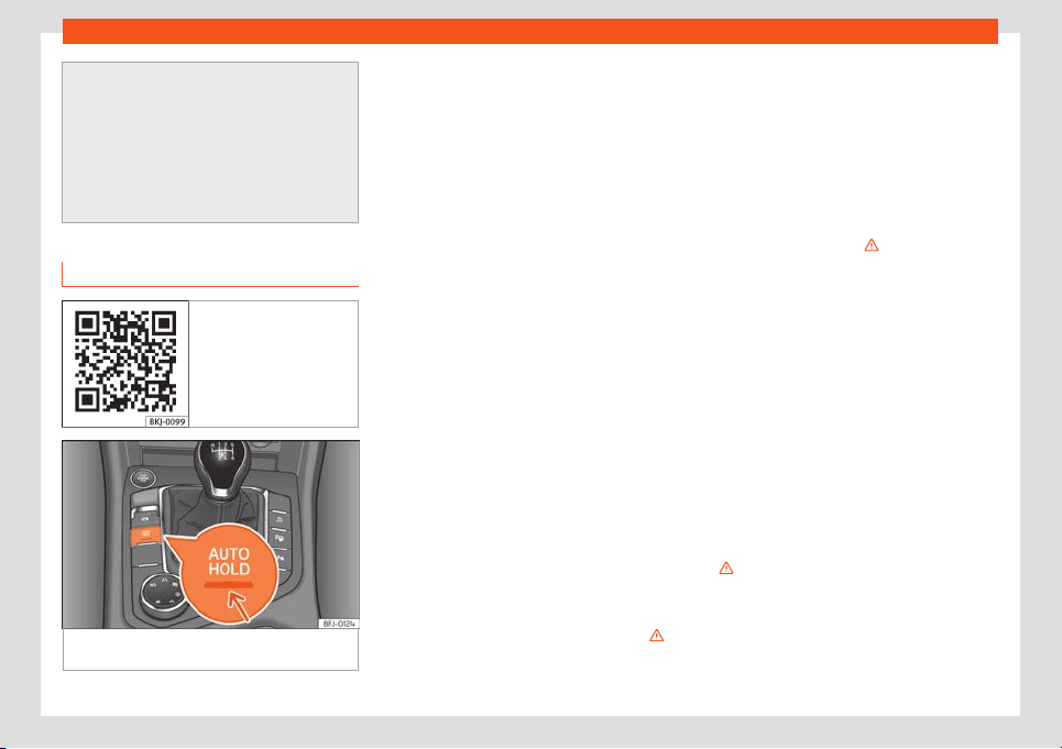
Braking and parking
parking brake. Use the jump-start
›››
page 51.
●
When the electronic parking br
ake is ap-
plied or released, noises may be heard.
●
The system performs automatic and au-
dible tests sporadically in the parked vehi-
cle if some time elapses without the elec-
tronic parking brake being used.
Auto Hold Function
Fig. 279 Related video
Fig. 280 In the lower part of the centre con-
sol
e: Aut
o Hol
d function butt
on.
The control lamp on button
›
›
›
Fig. 280
remains on while the Auto Hold
function is connected.
Once connected, the Auto Hold function as-
sists the driver in keeping the vehicle station-
ary at repeated intervals or for a certain peri-
od of time with the engine running, for exam-
ple, when going up a slope, when stopped at
traffic lights or in heavy traffic with intermit-
tent stops.
When connected, the Auto Hold function au-
tomatically prevents the vehicle from rolling
when stationary without pressing the brake
pedal.
After detecting that the vehicle is stationary
and the brake pedal has been released, the
Auto Hold function holds the vehicle. The driv-
er can lift their foot off the brake pedal.
When the driver touches the accelerator
pedal or accelerates slightly to continue driv-
ing, the Auto Hold function releases the brake.
The vehicle moves according to the slope of
the road.
If the vehicle is stationary and one of the con-
ditions required by the Auto Hold function is
impaired, it disconnects itself and the button's
control light goes out
›››
Fig. 280. The elec-
tronic parking brake connects automatically,
if necessary, to park the vehicle safely
›››
.
Conditions for keeping the vehicle station-
ary with the Aut
o Hol
d function
●
The driv
er door must be cl
osed.
●
The driv
er
's seat belt must be f
astened.
●
The engine is running.
Switching the Auto Hold function on and
off
Pulse button
›››
. The control lamp
on the butt
on goes out when the Aut
o Hol
d
function is s
wit
ched off
.
Aut
omatically engaging and disengaging
the Auto Hold function
If the Auto Hold function was switched on with
the button before disconnecting
the ignition, the function will remain on after
the ignition is re-connected.
If the Auto Hold function was not switched on,
it will automatically remain off next time the
ignition is engaged.
The Auto Hold function connects automat-
ically if the following conditions are met
(all points must be met at the same time
›››
):
The v
ehicl
e is k
ept
st
ationary
with the
br
ake pedal on a flat surface or on a
slope.
The engine rotates “correctly”.
»
1.
2.
301
Driving
The Auto Hold function is automatically
t
urned off if the f
oll
o
wing conditions ar
e
met:
If any of the conditions mentioned on
›
›
›
page 301, Conditions for keeping
the vehicle stationary with the Au-
to Hold function are no longer met.
If the engine is running irregularly or an
anomaly is detected.
If the engine is turned off or stalls.
Manual gearbox: The clutch and the ac-
celerator are pressed at the same time.
Automatic gearbox: If the accelerator is
pressed
Automatic gearbox: If any of the tyres
has only minimal contact with the
ground, e.g. in the case of axle articula-
tion.
WARNING
The smart technology incorporated into
the Auto Hold function cannot defy the
laws of physics; it only works within the lim-
its of the system. The great
er convenience
provided by the Auto Hold function should
never tempt you to take any risk that may
compromise safety.
●
Never leave the vehicle running and with
the Auto Hold function switched on.
●
The Auto Hold function cannot always
keep the vehicle stationary uphill or down-
1.
2.
3.
4.
5.
hill or stop it sufficiently, for example, on
slippery or frozen surfaces.
Note
Before entering a car wash, always switch
off the Aut
o Hold function, because if the
electronic parking brake is aut
omatically
connected, it may cause damage.
Stabilisation and brake as-
sist
ance syst
ems
Contr
ol l
amps
It lights up
Fault in the ESC or ABS, or disconnection caused by
the system.
The ESC works in combination with the ABS. If the
ABS fails, the lamp also lights up
.
Flashes
ESC or ASR activated.
It lights up
ASR manually deactivated.
Or: ESC in Sport mode
›››
page 304.
It lights up
ABS faulty or does not work.
The control lamps light up together when the
ignition is switched on and should turn off af-
ter appr
oximately 2 seconds. This is the time
taken for the function check.
Brake assist systems
Electronic Stability Control (ESC)
The ESC helps t
o impr
o
v
e saf
et
y. It r
educes
the tendency to skid and improves the stabili-
ty and roadholding of the vehicle. The ESC
detects critical handling situations, such as
vehicle understeer or oversteer, or wheelspin
on the driving wheels. It stabilises the vehicle
by braking individual wheels or by reducing
the engine torque. The warning lamp will
flash on the instrument panel when the ESC is
intervening .
The ESC includes the anti-lock brake system
(ABS), the hydraulic brake assist (HBA), the
traction control system (ASR), electronic dif-
ferential lock (EDS), electronic torque control
(XDS) and tractor-trailer sway mitigation*.
ESC also helps stabilise the vehicle by
changing the torque.
The ASR can be deactivated when wheel spin
is desirable
›››
page 304.
302

Braking and parking
Anti-lock brake system (ABS)
ABS pr
e
v
ents the wheel
s fr
om l
ocking up un-
der br
aking until the vehicle has reached a
virtual standstill. You can continue to steer the
vehicle even when the brakes are on full.
Keep your foot on the brake pedal and do not
pump the brakes. You will feel the brake pedal
pulsate while the ABS is working.
If the running gear or brake system is modi-
fied, the effectiveness of the ABS could be se-
verely limited.
Hydraulic Brake Assist (HBA)
The brake assist system can reduce the re-
quired braking distance. The braking force is
automatically boosted if you press the brake
pedal quickly in an emergency. You must
keep pressing the brake pedal until the dan-
ger has passed.
Traction control system (ASR)
In the event of wheelspin, the traction control
system reduces the engine torque to match
the amount of grip available. This helps the
car to start moving, accelerate or climb a
gradient.
Electronic differential lock (EDL)
When the EDL detects wheelspin, it brakes
the spinning wheel and directs the power to
the other driven wheel. This function is active
up to approximately 100 km/h (62 mph).
To prevent the disc brake of the braked wheel
from overheating, the EDL cuts out automati-
cally if subjected to excessive loads. The ve-
hicle can still be driven. The EDL will switch on
again automatically when the brake has
cooled down.
Tractor-trailer sway mitigation*
If the vehicle is pulling a trailer, it will control
the following: tractor-trailers tend to sway.
When the swaying of the trailer is felt by the
vehicle and detected by the ESC, it will auto-
matically brake the towing vehicle within the
limits of the system and mitigate the sway.
Tractor-trailer sway mitigation is not available
in all countries
›››
page 338.
Electronic engine torque management
(XDS)
When taking a curve, the driveshaft differen-
tial allows the outer wheel to turn at a higher
speed than the inner wheel. In this way, the
wheel that is turning faster (outer wheel) re-
ceives less drive torque than the inner wheel.
This may mean that in certain situations the
torque delivered to the inner wheel is too
high, causing the wheels to spin. On the other
hand, the outer wheel is receiving a lower
drive torque than it could transmit. This can
cause a loss of grip on the drive axle, in this
case the front axle, which results in under-
steer or “lengthening” of the trajectory.
The XDS can detect and correct this effect
via the sensors and signals of the ESC.
Via the ESC, the XDS will brake the inside
wheel and counter the excess driving torque
of that wheel. This means that the requested
trajectory is much more precise.
XDS works in combination with the ESC and is
always active, even when ASR is disconnec-
ted, or when the ESC is in Sport mode or dis-
connected.
Multi-collision brake
In an accident, the multi-collision brake can
help the driver by braking to avoid the risk of
skidding during the accident and causing
other collisions.
The multi-collision brake works for front, side
or rear accidents, when the airbag control
unit records its activation level and the acci-
dent takes place at a speed of over 10 km/h
(6 mph). The ESC automatically brakes the
vehicle, as long as the accident has not dam-
aged the ESC, the brake hydraulics or the on-
board network
The following actions control automatic brak-
ing during the accident:
●
When the driver presses the accelerator,
the automatic braking does not take place.
»
303
Driving
●
When the br
aking pr
essur
e thr
ough pr
ess-
ing the br
ak
e pedal is greater than the sys-
tem’s braking pressure the vehicle will brake
automatically.
●
Multi-collision braking will not be available
if ESC is malfunctioning.
WARNING
Driving at high speed on icy, slippery wet
ground can result in loss of vehicle control
and serious injury t
o the driver and passen-
gers.
●
The ESC, ABS, ASR, EDS and the electron-
ic torque control system cannot exceed the
limits imposed by the laws of physics. Al-
ways bear this in mind, especially on wet or
slippery roads. If you notice the systems
cutting in, you should reduce your speed
immediately to suit the road and traffic
conditions. Do not be encouraged to take
risks by the presence of more safety sys-
tems. If you do, an accident may occur.
●
Please remember that the accident risk
always increases if you drive fast, espe-
cially in corners or on a slippery road, or if
you follow too close behind the vehicle in
front of you. The ESC, ABS, brake assist,
EDS and the electronic torque control sys-
tem cannot prevent accidents: risk of acci-
dents!
●
Accelerate with caution on slippery sur-
faces (for e
xample, icy or snow-covered).
Despite the control systems, the driven
wheels could spin, affecting the stability of
the vehicle: risk of accident!
Note
●
The ABS and ASR will only oper
ate cor-
rectly if the four wheels hav
e identical
tyres. Any differences in the rolling radius
of the tyres can cause the system to re-
duce engine power when this is not desired.
●
The regulating processes of the systems
can make noises due to their operation.
●
If the warning lamp or lights up,
there could be a fault
›››
page 79.
●
Any modifications made to the vehicle
(for example, to the engine, brake system,
running gear or to the combination of
wheels and tyres) may affect the operation
of the ABS, ASR and EDS.
Connecting and disconnecting the
ESC and ASR
The ESC is switched on automatically when
the engine is st
art
ed, and only w
orks when
the engine is running and includes the ABS,
EDS and ASR syst
ems.
The ASR function shoul
d only be s
wit
ched off
in situations in which traction is insufficient.
Depending on the finishes and versions, there
is the possibility of disconnecting only the
ASR or activating the ESC in “Sport” mode.
Disconnecting and connecting the ASR
●
The ASR can be disconnected and connec-
ted using the Easy Connect system
›››
page 82. In vehicles with a driver informa-
tion system* the corresponding indication will
be displayed.
When the ASR is disconnected, the control
warning light lights up on the instrument
cluster.
Disconnecting and connecting the ESC in
“Sport” mode
●
In “Sport” mode, the ESC can be discon-
nected and connected using the Easy Con-
nect system
›››
page 82. In vehicles with a
driver information system* the corresponding
indication will be displayed.
When “Sport” mode is connected, the inter-
ventions of the ESC to stabilise the vehicle,
304
Braking and parking
and the anti-slip regulation (ASR
1)
) int
erv
en-
tions ar
e limit
ed. In addition, the
contr
ol
lamp lights up on the instrument panel.
ESC in “Offroad” mode
2)
Turn the Driving Experience button to select
the Offroad mode and connect it
›››
page 264. The interventions of the ESC, as
well as of the ASR, EDS and the ABS, adapt to
irregular terrain.
In the following exceptional situations it may
make sense to activate the Offroad mode to
allow the wheels to spin:
●
When “swinging” the vehicle to get it un-
stuck.
●
Driving in deep snow or on loose surfaces.
●
When driving on rough terrain with much of
the car's weight is lifted off the wheels (axle
articulation).
●
Steep descents with braking on unpaved
terrain.
For your safety we recommend that you turn
off the Offroad mode when it is not absolute-
ly necessary.
To disconnect the “Offroad” mode, select a
different driving mode.
ESC in “Snow” mode
2)
Turn the Driving Experience button to select
the “Snow” mode and connect it
›››
page 264. Traction control system (ASR)
interventions adjust to the adhesion of snowy
roads.
To disconnect the “Snow” mode, select a dif-
ferent driving mode.
WARNING
The ESC Sport mode should be activated
only when traffic conditions and the ability
of the driver allow it. Danger of skidding!
●
With ESC in Sport mode
, the stabilising
function will be limited to allow for a sporti-
er drive. The driving wheels could spin and
the vehicle could skid.
WARNING
You should only activate the Offroad Mode
or disable the ASR if the experience of the
driver and traffic conditions allow it. Dan-
ger of skidding!
●
With the Offr
oad mode activated, the
stabilisation function is limited. In particu-
lar, if the road is too smooth and slippery,
the driving wheels could spin and the vehi-
cle could skid.
Note
If the ASR is disconnected or the Sport
mode is sel
ected, cruise control* will be
switched off.
Parking
To park the vehicle
When parking your vehicle, all legal require-
ments shoul
d be observ
ed.
Al
w
ays not
e the f
oll
owing points when park-
ing the vehicle:
●
Park the vehicle on a suitable surface
›››
.
●
Connect the electronic parking brake
›
›
›
page 299
.
●
F
or an aut
omatic gearbo
x, move the selec-
tor lever to position P.
●
Switch the engine off and remove the key
from the ignition. Turn the steering wheel
slightly to engage the steering lock.
»
1)
In vehicles with 4-wheel drive, the ASR is dis-
connected completely
›››
.
2)
Only for 4Drive models.
305

Driving
●
With a manual gearbo
x, engage first gear
on fl
at gr
ound and sl
opes, or e
v
en r
everse
gear on hills, and release the clutch pedal.
●
When leaving the vehicle, take all keys with
you.
Additionally, on steep slopes and inclines
Before switching off the engine, rotate the
steering wheel so that if the vehicle should
move, it will be held by the kerb.
●
On slopes, turn the front wheels so that
they are against the edge of the kerb.
●
Uphill, turn the wheels towards the centre of
the road.
WARNING
●
Avoid parking the vehicle where the hot
exhaust system coul
d ignite inflammable
materials, such as dry grass, low bushes,
spilt fuel or flammable materials.
●
Do not leave passengers inside a closed
vehicle, they may not be able to open
doors or windows. Locked doors hinder the
possibility of a rescue.
●
Children should not be left alone in the
vehicle. They could tamper with the hand-
brake or the gears, which could cause the
vehicle to move without control.
●
Depending on weather conditions, it may
become extremely hot or cold inside the
vehicle. This can be fatal.
Note
In vehicles with automatic transmission, the
key can only be removed from the ignition
when the le
ver is in position P.
Help with parking and ma-
noeuvring
Assist
ed parking syst
em
(P
ark Assist)*
Intr
oduction
The Park Assist system is an additional
ParkPilot function
›››
page 314 and helps the
driv
er to:
●
find a suitable parking space,
●
select a parking mode,
●
park driving in reverse in suitable perpen-
dicular and parallel spaces,
●
park driving forwards in suit
able perpendic-
ular spaces,
●
exit a parking space driving forwards from a
parallel space.
In vehicles with a Park Assist system and fac-
tory infotainment system, the front, rear and
side areas are represented, and the position
of obstacles is shown relative to the vehicle.
The Park Assist system is subject to certain
limitations inherent to the system and its use
requires special attention by the driver
›››
.
306
Help with parking and manoeuvring
WARNING
The technology used in the park assist sys-
tem involves a series of limitations inherent
in the act
ual system and in the use of ultra-
sonic sensors. The use of Park Assist should
never tempt you to take any risk that may
compromise safety. The system is not a re-
placement for driver awareness.
●
Any accidental movement of the vehicle
could result in serious injury.
●
Adapt your speed and driving style at all
times to suit visibility, weather, road and
traffic conditions.
●
Certain surfaces of objects and gar-
ments do not reflect the ultrasound sen-
sors' signals. The system cannot detect, at
least correctly, these objects or people
wearing such clothes.
●
Ultrasound sensor signals may be affec-
ted by external sound sources. In certain
circumstances this may prevent them from
detecting people or objects.
●
The ultrasound sensors have blind spots
in which obstacles and people are not reg-
istered.
●
Monitor the area around the vehicle at all
times, since the ultrasound sensors do not
detect small children, animals or certain
objects in all situations.
WARNING
Quick turns of the steering wheel when
parking or exiting a parking space with
Park Assist can cause serious injury.
●
Do not hold the steering wheel during
manoeuvres to park or e
xit a parking space
until the system requests it. Doing so disa-
bles the system during the manoeuvre, re-
sulting in the parking being cancelled.
CAUTION
●
In certain circumstances, the ultrasonic
sensors do not detect ob
jects such as trail-
er tongues, bars, fences, posts or thin trees,
or an open (or opening) rear lid, which
could damage the vehicle.
●
Retrofitting of certain accessories to the
vehicle, such as a bicycle rack, may inter-
fere with the operation of the Park Assist
system and cause damage.
●
The Park Assist system uses as a refer-
ence parked vehicles, curbs and other ob-
jects. Make sure that the tyres and wheels
are not damaged while parking. If necessa-
ry, opportunely interrupt the parking ma-
noeuvre to avoid damaging the vehicle.
●
The ultrasound sensors on the bumper
may be damaged or shifted in the event of
a collision, for example, when entering or
exiting a parking space.
●
If you use high-pressure or vapour equip-
ment to clean the ultrasound sensors, do
not apply it directly unless very briefly and
always from a distance of more than 10 cm.
●
A registr
ation plate or plate holder on the
front with larger than the space for the reg-
istration plate, or a registration plate that is
curved or warped can cause:
–
false detections,
–
loss of sensor visibility.
–
cancellation of the parking manoeuvre
or defective parking.
●
If one of the ultrasonic sensors is dam-
aged, the area corresponding to that group
of sensors (front or rear) is deactivated and
cannot be activated until the fault is cor-
rected. However, you can still use the sen-
sors of the other bumper as per usual. If
there is a fault in the system, consult a spe-
cialist workshop. SEAT recommends visiting
a SEAT dealership for this.
Note
●
In order to guarantee good system oper-
ation, k
eep the ultrasound sensors of the
bumper clean, free of snow or ice, and do
not cover them with adhesives or other ob-
jects.
●
Certain sources of noise, such as rough
asphalt or paving stones and the noise of
other vehicles can induce the Park Assist
system or ParkPilot to give erroneous warn-
ings.
»
307
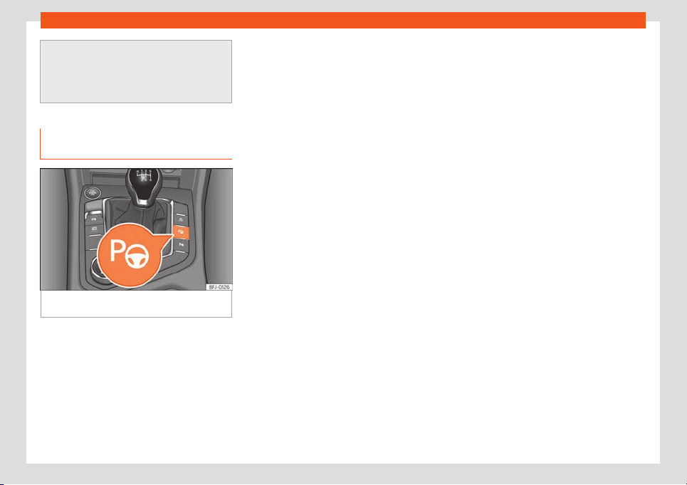
Driving
●
In order to become familiar with the sys-
tem and its functions, SEAT recommends
that you practice oper
ating the Park Assist
system in an area where there is not too
much traffic or in a car park.
Description of the parking assist
system
Fig. 281
In the upper part of the centre con-
sol
e: butt
on t
o s
wit
ch on the P
ark Assist syst
em.
The components of the Park Assist system
ar
e the ultr
asonic sensors l
ocat
ed in the fr
ont
and r
ear bumpers, the
button
›››
Fig. 281 to
switch the system on and off and the mes-
sages on the instrument panel display.
Prerequisites for parking
●
The traction control system (ASR) must be
turned on
›››
page 304.
●
Speed when passing next to the parking
space (parallel parking): do not exceed ap-
prox. 40 km/h (25 mph).
●
Speed when passing next to the parking
space (angle parking): do not exceed approx.
20 km/h (12 mph).
●
Keep a distance between 0.5 and 2.0 me-
tres when driving past the parking space.
●
Space length (parallel parking): vehicle
length + 0.8 meters.
●
Space width (angle parking): vehicle width
+ 0.8 meters.
●
Do not exceed approximately 7 km/h
(4 mph) when parking.
Requirements for leaving the parking
space (only for parallel parking)
●
The traction control system (ASR) must be
turned on
›››
page 304.
●
Space length: length of the vehicle + 0.5
metres.
●
Do not exceed approximately 7 km/h
(4 mph) when exiting the parking space.
Prematurely stopping or automatically in-
terrupting the manoeuvres for parking or
exiting a parking space
Park Assist interrupts the manoeuvres for
parking or exiting a parking space in any of
the following cases:
●
Press the button.
●
The speed exceeds approximately 7 km/h
(4 mph).
●
The driver takes hold of the steering wheel.
●
The parking manoeuvre does not end within
6 minutes from the activation of automatic
steering.
●
There is a fault in the system (the system is
temporarily unavailable).
●
ASR is switched off.
●
ASR or ESC intervene with regulation.
●
The driver door is opened.
To restart the manoeuvre it is necessary that
none of these things occur and that the
button is pressed again.
Special characteristics
The Park Assist system is subject to certain
limitations inherent to the system. For exam-
ple, it is therefore not possible to enter or exit
a parking space on sharp bends.
While entering or exiting a parking space, a
brief signal sounds to prompt the driver to
change between forward and reverse gears
(depending on the case). In successive ma-
noeuvres, the assistant tells the driver to
change gears, at the latest, when the contin-
uous audible signal is given (object present at
a distance of ≤30 cm) by Park Pilot.
308
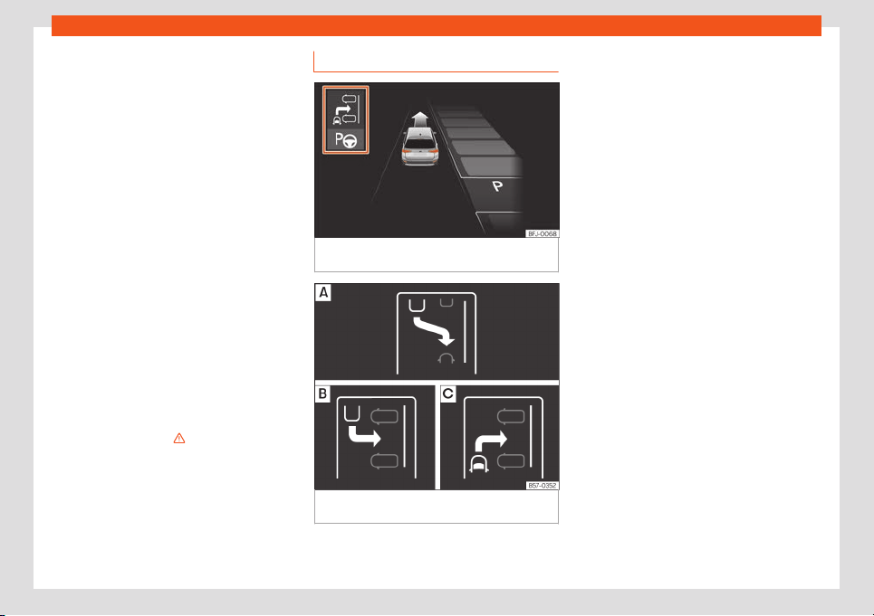
Help with parking and manoeuvring
When the Park Assist system turns the steer-
ing wheel with the v
ehicl
e st
ationary, the in-
strument panel al
so displ
ays the symbol
.
Keep the brake pedal depressed while the
symbol remains on the dash panel display to
turn the wheels with the vehicle stopped. This
way, the system will require fewer manoeu-
vres to complete the parking action.
Trailer mode
The Park Assist system cannot be switched
on if the factory-fitted towing bracket
›››
page 332 is electrically connected to a
trailer.
After changing a wheel
If, after changing a wheel, the vehicle stops
entering and exiting parking spaces correct-
ly, the circumference of the new wheel may
be different and the system may need to
adapt to it. The adaptation is automatic and
takes place during driving. Making turns slow-
ly and in both directions (20 km/h [12 mph])
for a few minutes may contribute to this
adaptation process
›››
in Introduction on
page 307.
Selecting a parking mode
Fig. 282
On the instrument panel display: view
of the parking assist syst
em with r
educed vie
w
.
Fig. 283 On the instrument panel display: indi-
cation of parking modes.
Parking assist has the following 3 parking
modes:
Reverse parallel parking.
R
e
v
erse angl
e parking.
F
orw
ar
d angle parking.
Selecting a parking mode after passing in
front of the space
After activating the Park Assist system and af-
ter detecting a parking space, the display on
the instrument panel proposes a parking
mode. The Park Assist system selects the
parking mode automatically. The selected
mode is shown on the instrument panel dis-
play
›››
Fig. 282. The reduced display of oth-
er possible parking modes is also shown
›››
Fig. 283. If the mode selected by the sys-
tem does not correspond to the desired
mode, you can select another mode by
pressing the button
›››
Fig. 281.
●
The necessary conditions to park with Park
Assist have to be met
›››
page 308.
●
Press the button.
●
A control lamp on the button lights up
when the system is switched on. Additionally,
the selected parking mode is shown on the
instrument panel display and the reduced
display shows another parking mode it can
be changed to.
●
Turn on the corresponding turn signal to-
wards the side of the road where you are
parking. The instrument panel displays the
side corresponding to the road. By default, if
»
309

Driving
the turn signal is not on, it parks on the right in
the dir
ection of tr
affic.
●
If necessary, pr
ess the
butt
on again t
o
change to the next parking mode.
●
Once you have switched to all possible
parking modes, if the button is pressed
again, the system switches off.
●
Press the button again to switch the sys-
tem back on.
●
Follow the instructions displayed on the in-
strument panel while paying attention to traf-
fic and drive the vehicle past the parking
space.
Special case of perpendicular parking
space to park forwards without driving
past first
●
The necessary conditions to park with Park
Assist have to be met
›››
page 308.
●
Drive forward towards the parking space
while paying attention to traffic and stop the
vehicle.
●
Press the button once.
●
A control lamp on the button lights up
when the system is switched on. Additionally,
the selected parking mode is shown on the
instrument panel display without reduced
display.
●
Release the steering wheel
›››
in Intro-
duction on page 307.
310

Help with parking and manoeuvring
Parking with the parking assist system
Fig. 284 On the instrument panel display: paral-
lel parking. Finding a parking space. Park
-
ing position. Manoeuvring.
Fig. 285 On the instrument panel display: angle
parking. Finding a parking space. Parking
position. Manoeuvring.
Message to move forwards
Y
our v
ehicl
e
P
ark
ed v
ehicl
e
Parking space detected
Message to park
Message to press the brake pedal
Progress bar
1
2
3
4
5
6
7
The necessary conditions have to be met to
park with P
ark Assist
›
›
›
page 308
and the
parking mode must be sel
ect
ed
›››
page 309.
Parking
●
Look at the display on the instrument panel
to see if the space has been detected as “ap-
propriate” and if the correct position for park-
ing has been reached
›››
Fig. 284
or
›››
Fig. 285 . The space is considered
“appropriate” if the display on the instrument
panel shows the message to park
5
.
●
Stop the vehicle and, after a brief pause,
engage the r
e
v
erse gear
.
●
R
el
ease the st
eering wheel
›››
in Intro-
duction on page 307.
»
311
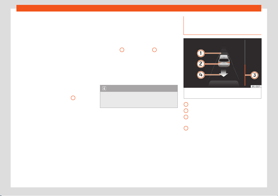
Driving
●
Pl
ease not
e the f
oll
o
wing message:
Auto-
matic steering enabled. Pay atten-
tion to your surroundings. Whil
e you
keep watch around you, carefully start accel-
erating up to no more than 7 km/h (4 mph).
During the parking manoeuvre, the system
only takes charge of the steering. You, as the
driver, have to accelerate, engage the
clutch if necessary, change gears and
brake.
●
Reverse until the continuous ParkPilot sig-
nal sounds; OR: reverse until the indication to
move forward appears on the instrument
panel display
›››
Fig. 284 or
›››
Fig. 285
; OR: reverse until the Park Assist fin-
ished message appears on the instrument
panel display. The progress bar
7
indicates
the dist
ance t
o co
v
er
›
›
›
page 312.
●
Press the brake pedal until the parking as-
sist system completes the steering wheel
turns; OR: until the symbol goes out on the
instrument panel screen.
●
Select first gear.
●
Move forward until the continuous ParkPilot
signal sounds; OR: move forward until the re-
verse indication appears on the instrument
panel display. The Park Assist system steers
the vehicle forward and back until it centres it
in the space
›››
Fig. 284 or
›››
Fig. 285 .
●
For best results, wait at the end of each
manoeuvre until the Park Assist system has
finished turning the steering wheel. The park-
ing manoeuvre ends when a corresponding
message is displayed on the instrument pan-
el and, in some cases, an acoustic signal
sounds.
Progress bars
The progress bar
›››
Fig. 284
7
and
›
›
›
Fig. 285
7
on the
scr
een of the instrument panel displ
ays the
r
el
ativ
e dist
ance t
o be covered. The greater
the distance, the fuller the progress bar.
When driving forward, the content of the pro-
gress bar decreases upwards, and when re-
versing, it decreases downwards.
Note
If the manoeuvre is terminated prematurely
during parking, the result may not be the
best.
Leaving a parking space with the
parking assist syst
em (only f
or par
-
all
el parking)
Fig. 286
On the instrument panel display: exit
a par
all
el parking space
.
Parked vehicle
Y
our v
ehicl
e in r
e
v
erse gear
Pr
ogress bar to indicate the distance left
to cover
Message giving the proposed manoeuvre
to exit the parking space
Leaving a parking space (parallel parking)
The necessary conditions to exit a parking
space with Park Assist have to be met
›››
page 308.
●
Press the button
›››
Fig. 281. A control
lamp on the button lights up when the sys-
tem is switched on.
1
2
3
4
312
Help with parking and manoeuvring
●
T
urn on the corr
esponding t
urn signal t
o-
w
ar
ds the r
oad you will enter when exiting the
parking space.
●
Select reverse gear.
●
Release the steering wheel
›››
in Intro-
duction on page 307. Pl
ease not
e the f
ol
-
l
o
wing message:
Automatic steering en-
abled. Pay attention to your sur-
roundings. While you keep watch around
you, carefully start accelerating up to no
more than 7 km/h (4 mph). When exiting the
parking space, the system only takes charge
of the steering. You, as the driver, have to
accelerate, engage the clutch if necessa-
ry, change gears and brake.
●
Reverse until the continuous ParkPilot sig-
nal sounds; OR: reverse until the instrument
panel display shows the forward indication.
The progress bar
›››
Fig. 286
3
indicates the
dist
ance t
o co
v
er
›
›
›
page 312.
●
Press the brake pedal until the parking as-
sist system completes the steering wheel
turns; OR: press the brake pedal until the
symbol goes out on the instrument panel
screen.
●
Move forward until the continuous ParkPilot
signal sounds; OR: move forward until the re-
verse indication appears on the instrument
panel display. The Park Assist system steers
the vehicle forward and back until it can exit
the space.
●
The vehicle can exit the space when a cor-
responding message is displayed on the in-
strument panel and, in some cases, an
acoustic signal sounds. Take charge of the
steering with the turning angle set by the Park
Assist system.
●
Paying attention to the traffic, exit the park-
ing space.
Automatic operation of the brakes
by the parking assist system
Park Assist helps the driver by automatically
br
aking in cert
ain sit
uations.
The driv
er is al
w
ays r
esponsible for braking in
time
›››
.
Aut
omatic br
aking int
erv
ention t
o av
oid
e
xceeding the speed limit
To avoid exceeding the allowed speed of ap-
prox. 7 km/h (4 mph) when entering or leaving
a parking space, the brakes may activate au-
tomatically. After automatically activating
the brakes, the manoeuvres to enter or exit a
parking space may continue.
The brakes are only automatically activated
once for each attempt to enter or exit a park-
ing space. If the speed of approximately
7 km/h (4 mph) is exceeded again, the corre-
sponding operation is halted.
Automatic braking to reduce damages
Depending on certain conditions, the Park
Assist system can automatically brake the
vehicle when faced with an obstacle, briefly
actioning and holding down the brake ped-
al
›››
. Following this the driver must press
the br
ak
e pedal.
Aut
omatic br
aking int
erv
ention t
o reduce
damage leads to the parking manoeuvre fin-
ishing.
WARNING
The automatic braking intervention by Park
Assist should never tempt you to tak
e any
risk that may compromise safety. The sys-
tem is not a replacement for driver aware-
ness.
●
The Park Assist system is subject to cer-
tain limitations inherent to the system. In
certain situations, the automatic braking
intervention may only work in a limited way
or not work at all.
●
Always be ready to use the brakes your-
self!
●
The automatic braking intervention will
end after approximately 1.5 seconds. After-
wards, brake the vehicle yourself.
313
Driving
Parking aid parking and ma-
noeuvring (P
arkPil
ot)
Intr
oduction
These assist systems help you when parking
and manoeuvring:
–
Park assist plus. It is an assistant that gives
a visual and audio warning of obstacles de-
tect
ed in front and behind the vehicle
›››
page 315.
–
Rear parking aid. An audio and visual as-
sistant that warns of obstacles located
be-
hind the vehicle
›››
page 319.
WARNING
●
Always pay attention, by looking directly,
to tr
affic and the area around the vehicle.
Assistance systems are not a replacement
for driver awareness. Responsibility always
lies with the driver.
●
The sensors have blind spots in which ob-
stacles and people are not detected. Pay
special attention to children and animals.
●
Always keep visual control of the sur-
roundings: use the mirrors for additional
help.
CAUTION
Parking distance warning system functions
can be affected by different factors that
can cause damage:
●
Under cer
tain circumstances, the system
does not detect or display certain objects:
–
Chains, trailer draw bars, bars, fences,
posts and thin trees.
–
Objects that are located above the
sensors, such as protrusions in a wall.
–
Objects with certain surfaces or struc-
tures, such as wire mesh fences or pow-
der snow.
●
Certain surfaces of objects and gar-
ments do not reflect the ultrasound sen-
sors' signals. The system cannot detect
these objects or people wearing such
clothes correctly.
●
Sensor signals may be affected by exter-
nal sound sources. This may prevent them
from detecting people or objects.
●
If the system warns you of the proximity
of a low obstacle, please note that after
being detected by the system, the obstacle
in question may disappear from the meas-
urement sensors as the vehicle moves clos-
er, and the system will no longer warn of its
presence. In certain circumstances, ob-
jects such as high kerbs that could damage
the underside of the vehicle are not detec-
ted.
●
If the parking distance warning system is
ignored, the vehicle coul
d suffer considera-
ble damage.
●
Damage to the radiator grille, bumper,
wheel arch and vehicle underbody can
modify the orientation of the sensors. This
can affect the parking aid function. Have
the function checked by a specialised
workshop.
●
A number plate or number plate holder
with dimensions that exceed the space for
the number plate, or a cured or deformed
number plate can cause false detections or
a loss of visibility for the sensors.
Note
●
The display on the Easy Connect screen
shows a slight time delay.
●
In certain sit
uations, the system can give
a warning even though there is no obstacle
in the detected area;
–
rough or cobbled surfaces or with long
grass,
–
external ultrasound sources, such as
other vehicles equipped with ultra-
sound systems,
–
downpours, heavy snow, hail or dense
exhaust gases,
–
if the number plate is not perfectly se-
cured to the bumper surface,
–
in gradient changes.
314
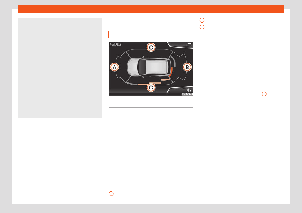
Help with parking and manoeuvring
●
In order to guarantee good operation,
keep the sensors cl
ean, free of snow and
ice, and do not cover them with stickers or
other objects.
●
If you use high-pressure or vapour equip-
ment for cleaning, do not apply it directly,
unless you do so very briefly, and always
keep a distance of more than 10 cm away.
●
Fitting certain accessories to the front of
the vehicle, such as a plate holder with ad-
vertising, may interfere with the operation
of the Park Assist.
●
We recommend that you practice park-
ing in an area without traffic.
●
The volume and tone of the signals and
indications can be changed
›››
page 319.
●
Please observe information on towing a
trailer
›››
page 320.
Parking System Plus*
Description
Fig. 287
Parking Aid display on the Easy Con-
nect syst
em scr
een.
Parking aid plus assists the driv
er by giving
visual and audio w
arnings about obst
acl
es
det
ect
ed in fr
ont of and behind the vehicle.
The bumpers are fitted with sensors. When an
obstacle is detected, it is indicated by audible
signals and in the Easy Connect system
›››
Fig. 287.
When moving close to an obstacle, it is possi-
ble to know if the obstacle is in front of the ve-
hicle or behind it by choosing different
sounds.
The approximate measurement range of the
sensors is:
1.20 m
A
1.60 m
0.90 m
As you appr
oach the obst
acl
e
, the fr
equency
of the audibl
e signal
s will increase. The signal
will sound continuously at around 0.30 m:
Stop!
If separation is maintained, the warning vol-
ume reduces after about 4 seconds.
In order to view the entire periphery of the ve-
hicle, the vehicle must be moved a few me-
tres forwards or backwards. Thus, the missing
areas are screened and obstacles at the
sides of the vehicle are displayed
C
.
Special f
eat
ur
es of P
arkPil
ot with Ar
ea
Vie
w
In the following situations the screened area
on the side of the vehicle is automatically hid-
den:
●
When a vehicle door is opened.
●
When the ASR is switched off.
●
When there is ASR or ESC regulation.
●
If the vehicle remains stationary for more
than approximately 3 minutes.
B
C
315
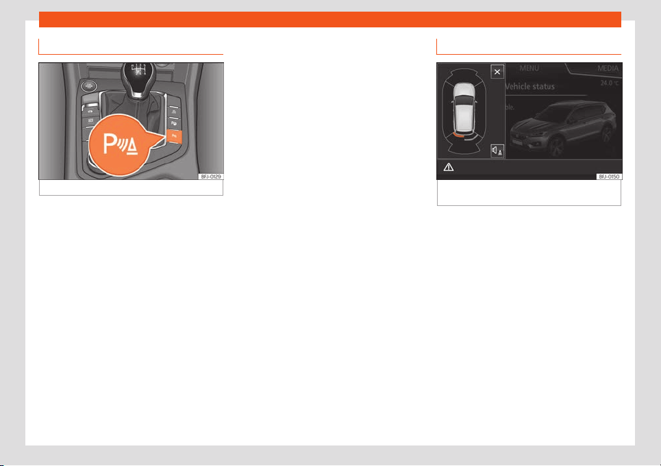
Driving
Parking Aid operation
Fig. 288
Centre console: parking aid button.
Manually connecting and disconnecting
the parking aid
●
Press the butt
on
once
.
Manual disconnection of P
arking Aid dis-
pl
ay (the audibl
e sounds r
emain active)
●
Press a button on the main menu of the fac-
tory-assembled infotainment system.
●
OR press the BACK function button.
Automatic connection of Parking Aid
●
Select reverse gear.
●
OR: If you drive forward at a speed of less
than 15 km/h (9 mph) and you encounter an
obstacle, it is detected when it is approx. less
than 95 cm. away. If the automatic connec-
tion is activated, a reduced display is shown
›››
Fig. 289.
●
OR: if the vehicle moves backwards.
Automatic disconnection of Parking Aid
●
Move the selector lever to position P.
●
OR: drive forwards at 15 km/h (9 mph) or
faster.
Temporary suppression of sound in Park-
ing Aid
●
Press the function button.
Change from reduced view to full view
●
Select reverse gear.
●
OR: press the car icon on the reduced view.
Switch to the reverse assist image (Rear
View Camera “RVC”)
●
Select reverse gear.
●
OR press the RVC function button.
A short confirmation signal will be heard and
the button symbol will light up when the sys-
tem is switched on.
Automatic activation
Fig. 289
Miniature indication of automatic ac-
tiv
ation.
When the parking aid plus connects aut
o-
matically, a diagr
am of the v
ehicl
e and the
segments will appear on the l
eft of the dis-
pl
ay
›
››
Fig. 289.
It only operates every time the speed is re-
duced below 15 km/h (9 mph) for the first
time.
If it is switched off using the button, one of
the following actions must be taken for it to
reactivate automatically:
●
Switch off the ignition and switch it on
again.
●
OR: drive forward at over 15 km/h (9 mph)
approx.
●
OR: move the lever into position P and pack
again.
316
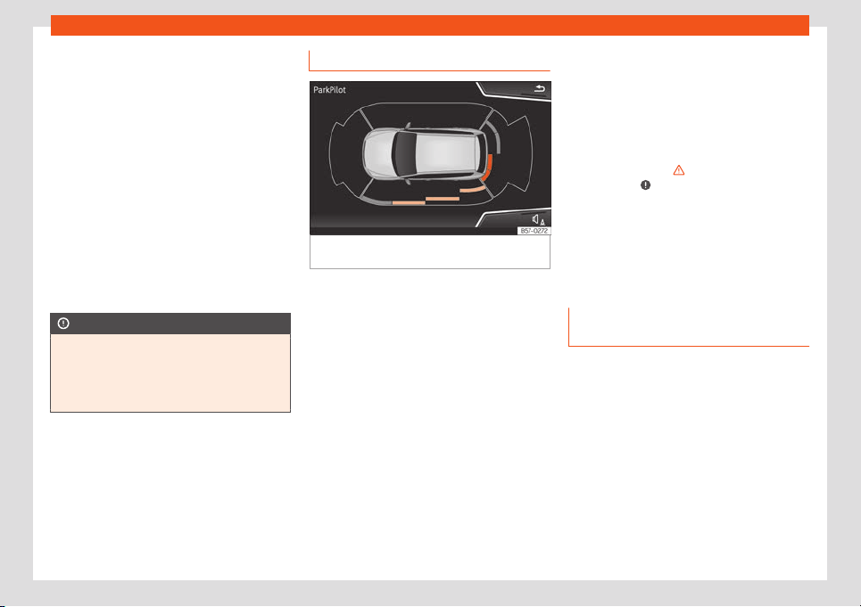
Help with parking and manoeuvring
●
OR: s
wit
ch the aut
omatic activ
ation on and
off in the Easy Connect syst
em.
The aut
omatic activ
ation of the parking aid
can be switched on and off in the Easy Con-
nect system
›››
page 82:
●
Switch the ignition on.
●
Select: infotainment button > SETTINGS
> Parking and manoeuvring.
●
Select Automatic activation. If the box
is checked , the function is connected.
If activated automatically, an audible sound
warning will only be given when obstacles in
front are at a distance of less than 50 cm. ap-
prox.
CAUTION
The automatic connection of the Parking
Aid only works when you are driving slowly.
If driving style is not adapt
ed to the circum-
stances, an accident and serious injury or
damage may be caused.
Visual indication segments
Fig. 290
Parking Aid display on the Easy Con-
nect syst
em scr
een.
The optical indication of the segments works
as f
oll
o
ws:
Whit
e segments:
the obst
acl
e is more
than approx. 30 cm away from the path
or in the direction opposite to travel.
They are also displayed when the elec-
tronic parking brake is activated.
Yellow segments: the obstacles lie on
the vehicle’s path and are at a distance
of less than approx. 30 cm away.
Red segments: obstacles are less than
approx. 30 cm away.
With the Media System Plus, Navi System or
Navi System Plus, yellow lines show the ex-
pected trajectory based on turns of the steer-
ing wheel.
–
–
–
If an obstacle is located in the vehicle’s way,
the corresponding audible warning will
sound.
When the penultimate segment is displayed,
the vehicle has reached the collision zone. In
the collision zone, the obstacles are repre-
sented in red, including those out of the path.
Stop the vehicle!
›››
in Introduction on
page 314,
›
›
›
in Introduction on
page 314 !
In the e
v
ent the car is equipped with the T
op
Vie
w Camer
a syst
em, P
ark Assist visual guid-
ance will appear in accordance with the view
selected in the Top View Camera system.
Setting the indications and audio
signals
The indications and audio signal settings are
in Easy Connect*
›
›
›
page 82
.
Aut
omatic activ
ation
on – off.
Front volume*
Volume in the front and rear area.
Front sound settings/sharpness*
Sound tone in the front area.
»
317
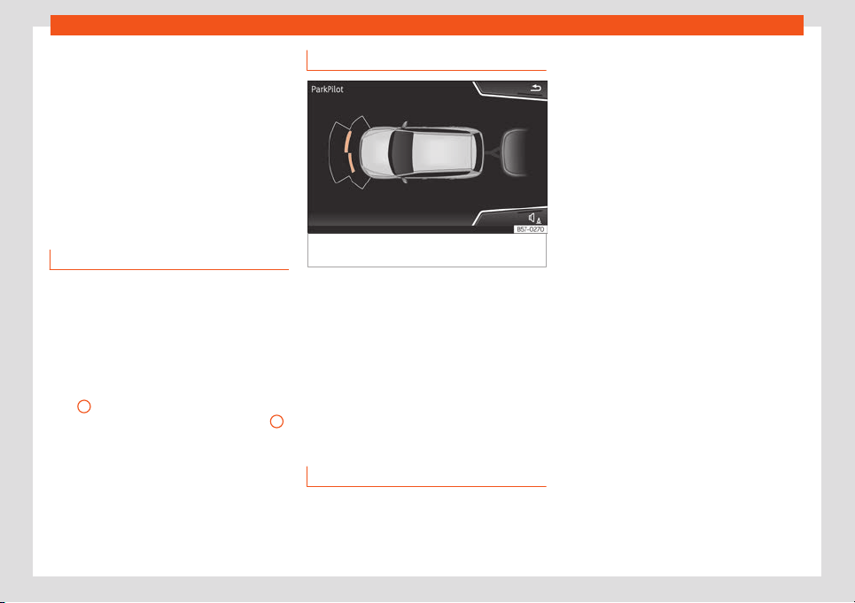
Driving
Rear volume*
V
olume in the r
ear ar
ea.
R
ear sound settings/sharpness*
Sound t
one in the r
ear ar
ea.
Adjust volume
When the parking aid is switched on, the vol-
ume of the audio source will be reduced, de-
pending on the selected option.
Error messages
If a an error or fault message appears on the
instrument panel in P
arking assist, ther
e is a
f
ault.
If the f
ault doesn'
t disappear bef
or
e discon-
necting the ignition, it will not be indicated
next time the parking aid is connected.
If a rear sensor is faulty, only the obstacles in
area
A
are displayed
›
›
›
Fig. 287
. If a fr
ont
sensor is f
ault
y, only the obstacles in area
B
are displayed. Symbol is displ
ayed.
W
e r
ecommend t
aking the v
ehicl
e t
o a speci-
alised workshop to have the fault repaired.
Trailer mode
Fig. 291
Parking assist display on the screen
with tr
ail
er att
ached.
On vehicles with a factory-fitted trailer hitch,
when the tr
ail
er is connect
ed, the r
ear sen-
sors will not activ
at
e when r
everse gear is en-
gaged or button is pressed. Therefore, any
objects behind or to the side of the vehicle
will not be indicated on the screen and no
audio signals will sound.
The screen will only display objects detected
at the front, and the vehicle's trajectory will
be hidden.
Manoeuvre braking function*
3 Only valid with Parking System Plus
The emergency braking function is used to
minimise damage in the e
vent of a collision.
Depending on the equipment, if the Parking
Aid is active, the braking while manoeuvring
function activates emer
gency braking when it
detects an obstacle in the vehicle’s path that
could cause a collision, driving forwards or in
reverse.
The function will not brake if the Parking Aid is
activated automatically. For the system to
operate, manoeuvring speed must be be-
tween 2.5 and 10 km/h (between 1.5 and 6
mph) for the front area and between 1.5 and
10 km/h (between 1 and 6 mph) for the rear.
Following an intervention, the braking while
manoeuvring function will be inactive in the
same direction of travel for 5 metres. Once
the gear is changed, or the selector lever’s
position is changed, the function will be ac-
tive again. The Parking Aid’s limitations apply.
The manoeuvre braking function is set in the
Easy Connect system with button > SET-
TINGS > Parking and manoeuvring.
●
on – permits the use of the braking while
manoeuvring function.
●
off – does not permit the use of the
braking while manoeuvring function.
Tempor
ary suppression of emergency
braking
●
When the function is deactivated with the
Manoeuvre braking button that appears on
318

Help with parking and manoeuvring
the P
arking assist screen of the Easy Con-
nect syst
em.
●
Whene
v
er any of the car doors, r
ear lid or
bonnet ar
e opened.
R
ear parking aid*
Description
The rear parking aid is an audible and visual
assistant that warns of obstacles locat
ed be-
hind the vehicle.
There are sensors integrated in the rear
bumper. When they detect an obstacle, you
are alerted by audible warnings and visually
on the Easy Connect system.
If the Top View Camera* is installed, the rear
parking aid will issue an audible warning
about objects near the rear of the vehicle,
and the Top View Camera* image will be
available on the Easy Connect screen, giving
a real image of the objects around the car.
Make particularly sure that the sensors are
not covered by adhesives, residues, dirt and
the like, as this could affect the system's op-
eration. Cleaning instructions
›››
page 377.
The approximate measurement range of the
rear sensors is:
0.60 mSide area:
1.60 m
As you approach the obstacle, the frequency
of the audible signal
s will increase. The signal
will sound continuously at around 0.30 m:
Stop!
›››
in Introduction on page 314,
›
›
›
in Introduction on page 314!
If the separ
ation is maint
ained, the w
arning
v
olume is r
educed aft
er about 4 seconds.
P
arking Aid operation
Parking Aid connection
●
Select reverse gear.
P
arking Aid disconnection
●
Pl
ace the sel
ect
or l
e
v
el in position P, N or D
(for automatic gearboxes) or disengage re-
verse (for manual gearboxes).
Set the lever to the N or D position to maintain
the system active for approximately 8 sec-
onds before switching off. During that time,
Parking assist will switch off if:
●
The selector lever is moved to position P.
●
OR: the vehicle accelerates to approx.
15 km/h (9 mph) or faster.
If the Top View Camera* is installed, rear
parking aid will be automatically deactivated
when disengaging reverse gear.
Central area: Manual disconnection of Parking Aid dis-
play (the audible sounds remain active)
●
Press a button on the main menu of the fac-
tory-assembled infotainment system.
●
OR press the BACK function button.
Temporary suppression of sound in Park-
ing Aid
●
Press the function button. If you have the
Top View Camera* system installed, you can-
not use the temporary suppression of sound
in Parking Aid.
Change from reduced view to full view
●
Select reverse gear.
●
OR: on vehicles fitted with reverse assist
(Rear View Camera “RVC”) click on the car
icon of the reduced display.
Switch to the reverse assist image (Rear
View Camera “RVC”)
●
Select reverse gear.
●
OR: press the RVC function button.
Setting the indications and audio signals
The indications and audio signal settings are
in Easy Connect*
›››
page 82.
●
Rear volume*: volume in the rear area.
●
Rear sound settings/treble*: sound
tone in the rear area.
»
319
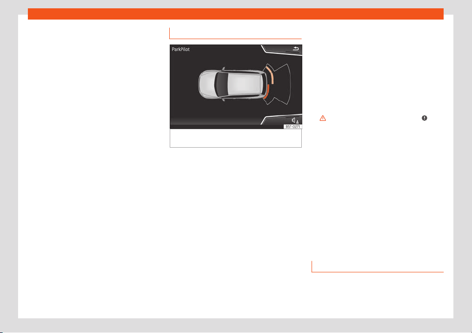
Driving
●
Lower volume: when the parking aid is
s
wit
ched on, the v
olume of the audio sour
ce
will be r
educed, depending on the sel
ect
ed
option.
Error messages
If a an error or fault message appears on the
instrument panel in Parking assist, there is a
fault.
If the fault doesn't disappear before discon-
necting the ignition, it will not be indicated
next time the parking aid is connected.
If there is a fault in a sensor, the symbol is
displayed on the Easy Connect display.
We recommend taking the vehicle to a speci-
alised workshop to have the fault repaired.
Towing device
In vehicles equipped with a towing bracket
device from the factory, when the trailer is
connected, the parking aid will not be activa-
ted when reverse gear is engaged.
Visual indication segments
Fig. 292
Parking Aid display on the Easy Con-
nect syst
em scr
een.
The distance to the obstacles can be estima-
t
ed with the help of the segments at the r
ear
of the v
ehicl
e
.
The optical indication of the segments w
orks
as f
ollows:
White segments: the obstacle is more
than approx. 30 cm away from the path
or in the direction opposite to travel.
They are also displayed when the elec-
tronic parking brake is activated.
Yellow segments: the obstacles lie on
the vehicle’s path and are at a distance
of less than approx. 30 cm away.
Red segments: obstacles are less than
approx. 30 cm away.
–
–
–
Whenever the obstacle is located in the vehi-
cle’s direction of travel, the corresponding
audible warning will sound.
As the vehicle approaches an obstacle, the
segments are displayed closer to the vehicle.
When the penultimate segment is displayed,
this means that the vehicle has reached the
collision zone. In the collision zone, the obsta-
cles are represented in red (including those
out of the path). Do not continue to reverse
›››
in Introduction on page 314,
›
›
›
in
Intr
oduction on page 314
!
If you ar
e equipped with the T
op Vie
w
Camer
a*
Segments ar
e not displayed when the vehicle
is equipped with Top View Camera*.
The Parking Aid system will issue an audible
warning for objects that are near the rear of
the vehicle, and the Top View Camera* im-
age will be available on the screen, giving a
real image of the objects around the car.
Trailer Assist
Introduction
Trailer assist helps the driver to reverse and
manoeuvr
e with a tr
ail
er
.
320
Help with parking and manoeuvring
By moving the rotary knob of the exterior mir-
r
ors, the tr
ail
er assist dir
ects the tr
ail
er that is
hit
ched. The driver has to accelerate, change
gears and brake!
System limitations
Under certain circumstances, the camera
does not detect objects such as trailer draw
bars, bars, fences, posts or thin trees, or an
open (or opening) rear lid, which could dam-
age the vehicle.
In order to guarantee good system operation,
keep the camera clean, free of snow or ice,
and do not cover it with adhesives or other
objects. Do not allow the draw bar to be cov-
ered by external influences.
Use the trailer manoeuvre assistant only
when the rear lid is closed correctly.
CAUTION
The trailer maneuver assistant does not
take the vehicle’s surr
ounding as a refer-
ence. No obstacle detection takes place.
The driver alone has to assess whether it is
possible to manoeuvre safely with the tow
vehicle and trailer set.
●
Always observe the movement of the
trailer and, if necessary, actively interrupt
the manoeuvre to avoid damage. Even if
the trailer manoeuvring assistant is operat-
ed correctly, on rare occasions the trailer
may move in a different way to the setting.
●
Do not rely solely on the indications on
the instrument cluster display.
Note
The trailer manoeuvre assistant automati-
cally s
witches off approx. 10 minutes after
being activ
ated. The assistant is also deac-
tivated if the driver does not perform any
action over the course of approx. 3 mi-
nutes.
Requirements
The following requirements must be met for
the tr
ail
er manoeuvr
e assist
ant t
o w
ork:
●
The engine is running.
●
The ESC must be connect
ed.
●
The driver's door and the rear lid are
closed.
●
The exterior mirrors are not folded.
●
There is a non-articulated one or two axle
trailer hitched and electrically connected.
●
Both the tow vehicle and trailer are stop-
ped.
●
The maximum bending angle has not been
exceeded.
●
The length of the trailer’s drawbar has been
determined.
Determine the length of the trailer's draw-
bar
In order for the trailer manoeuvre assistant to
determine the length of the trailer’s drawbar,
drive the vehicle-trailer set through some
turning manoeuvres or curves. The more pre-
cisely the length of the drawbar is deter-
mined, the wider the angles that will be avail-
able when manoeuvring. The assistant subdi-
vides the maximum available end stops of the
angle indicator into four levels: approx. 30°,
45°, 60° and 75°.
Note
For technical reasons, the trailer manoeu-
vre assistant cannot always correctly de-
tect tr
ailers with LED technology taillights.
321
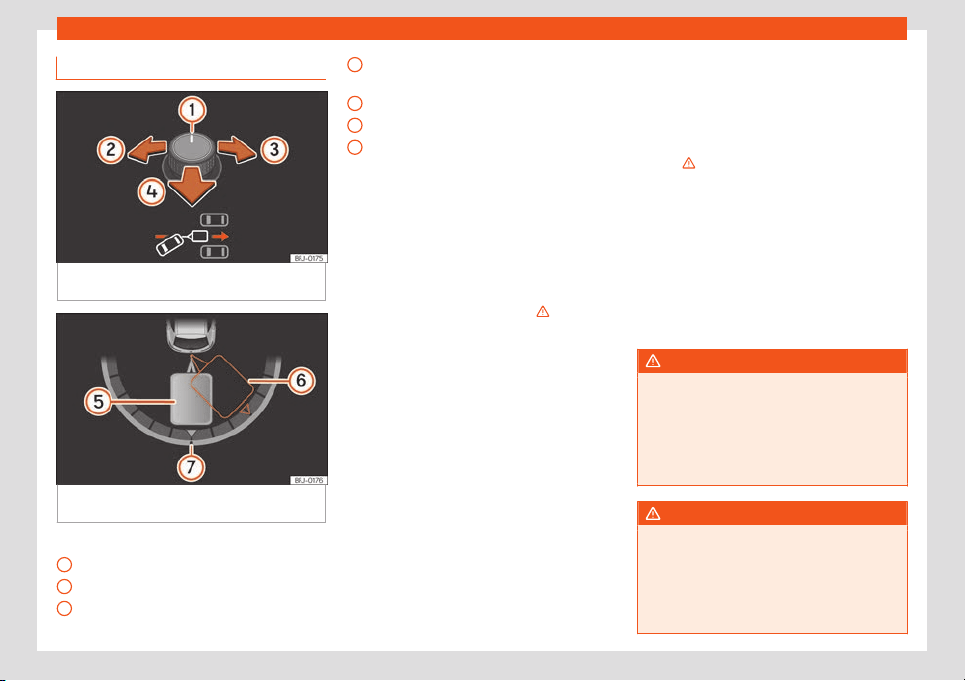
Driving
Operating
Fig. 293
Rotary exterior mirror controls.: ad-
just the tr
ail
er angl
e
.
Fig. 294 Instrument panel display: engage re-
v
erse gear
Key of the Fig. 293,
›
›
›
Fig. 294
:
R
ot
ary e
xterior mirror controls.
Trailer orientation to the left
Trailer orientation to the right
1
2
3
Move the vehicle in the direction of the
t
o
wing de
vice
.
Act
ual tr
ail
er position
Target trailer position
Angle indicator zero position
Manoeuvre with the tow vehicle and trailer
set
The system requirements must be met
›››
page 321.
●
Select reverse gear.
●
Press button .
●
Release the steering wheel
›››
.
●
Tilt the rotary control until the desired di-
r
ection is r
eached
›
›
›
Fig. 293
. A r
epresenta-
tion of the tow vehicle and trailer set is shown
on the instrument cluster screen for guidance
purposes
›››
Fig. 294.
●
Reverse by accelerating slowly. Pay atten-
tion to your surroundings!
●
If necessary, correct the angle with the ro-
tary control. Press the control towards the left
or right: the set will move to the left or right.
Press the control backwards: the vehicle will
follow the trailer.
●
Reverse and move forwards until the de-
sired position is reached.
●
The manoeuvre ends when a message is
displayed on the instrument cluster display
and, in some cases, an audio signal sounds.
4
5
6
7
Automatic brake operation
The tr
ail
er manoeuvr
e assist
ant helps the
driv
er by aut
omatically oper
ating the brakes
in certain situations.
The driver is responsible for braking in
time
›››
.
The br
ak
es may be applied aut
omatically
and the function deactiv
at
ed in the f
oll
owing
situations:
●
A certain speed is exceeded.
●
The steering wheel is grabbed. The vehicle
brakes automatically until it stops.
●
If the key is pressed during the manoeu-
vre or the driver’s door opens.
WARNING
The quickly turning steering wheel can
cause serious injuries.
●
Do not hold the steering wheel during the
manoeuvre until the system requests it.
●
Exception: If a dangerous situation oc-
curs, int
ervene and take over the steering.
WARNING
Never allow the automatic operation of
brakes to lead you to tak
e any risk that
compromises safety. The system is not a
replacement for driver awareness.
●
The manoeuvre assist system is subject
to certain limitations inherent to the
322
Help with parking and manoeuvring
system. In certain situations, the automatic
braking intervention may only work in a
limited way or not w
ork at all.
●
Always be ready to use the brakes your-
self!
●
Automatic brake operation ends after 1.5
seconds approx. if the vehicle is stopped.
After this, brake the vehicle yourself.
Note
The exterior mirrors cannot be adjusted
whil
e the assistant is active. The saved set-
ting f
or the passenger’s mirror can be acti-
vated
›››
page 121.
Problems and solutions
Camera with no visibility, fault message,
the syst
em disconnects
●
Cl
ean the camer
a or r
emo
v
e possibl
e ad-
hesives or accessories from it
›››
page 378.
●
Check for visible damage.
The system behaves differently than ex-
pected
There can be several causes:
●
The camera is dirty
›››
page 378. In addi-
tion to dirt and snow, camera visibility can be
reduced by detergent residue or any type of
coating.
●
The system requirements must be met
›››
page 321.
●
The camera is covered with water.
●
The vehicle has some type of damage in
the camera area, e.g. due to a parking im-
pact.
●
The field of view of the camera is blocked
by an accessory, e.g. a bicycle carrier sys-
tem.
●
Changes have been made to the paint in
the camera area and structural modifications
have been made, e.g. to the front part of the
vehicle and the running gear.
Solution for all cases
●
Temporarily disconnect the system.
●
Check if one of the causes indicated above
has occurred.
●
Once the source of the problem has been
eliminated, the system may be reconnected.
●
If the system still behaves unpredictably,
have it checked by a specialised workshop.
Peripheral view system (Top
View Camera)*
Introduction
Using 4 cameras, the system generates a
representation that is shown on the infotain-
ment syst
em display. The cameras are loca-
ted on the radiator grille, the exterior mirrors
and the rear lid.
The functions and representations of the Area
View system may vary depending on whether
or not the vehicle has ParkPilot.
WARNING
The image from the cameras does not
make it possible to calculate the dist
ance
to the obstacles (people, vehicles, etc.)
precisely, so using them could cause seri-
ous accidents and injury.
●
The camera lenses augment and distort
the visual field and the objects on the
screen are seen differently and imprecise-
ly.
●
Certain objects may not be shown or may
not be shown very clearly, for example,
posts or thin rails, due to the screen resolu-
tion or if light conditions are insufficient.
●
The cameras have blind spots in which
obstacles and people are not registered.
●
The camera lens must be kept free, with-
out snow or ice, and should not be covered.
»
323
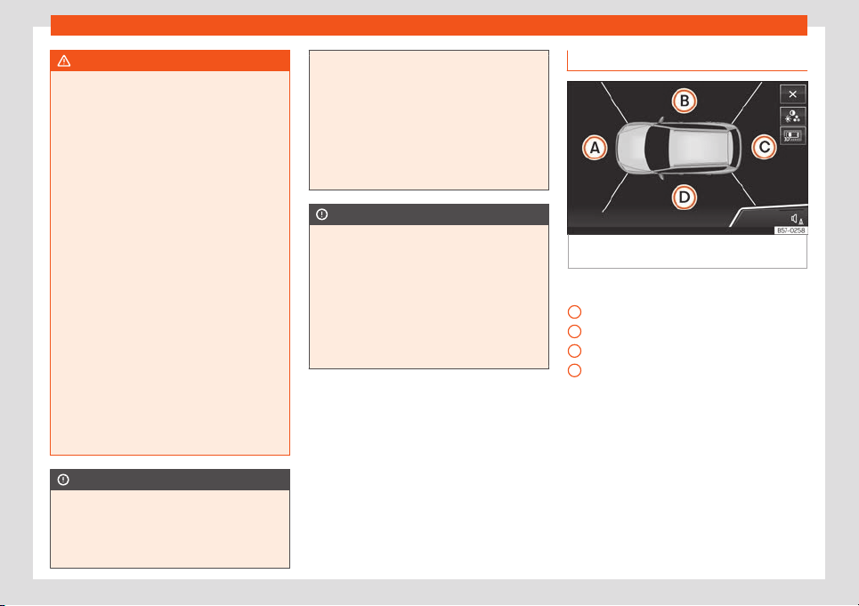
Driving
WARNING
The smart technology incorporated into
the Top View Camera* system cannot over
-
come the limits imposed by the laws of
physics and it only works within the limits of
the system. The greater convenience provi-
ded by the Area View system should never
tempt you to take any risk that may com-
promise safety. If used negligently or invol-
untarily, it may cause serious accidents
and injuries. The system is not a replace-
ment for driver awareness.
●
Adapt your speed and driving style to suit
visibility, weather, road and traffic condi-
tions.
●
Do not be distracted from the traffic by
looking at the screen.
●
Monitor the area around the vehicle at all
times, since the cameras do not capture
small children, animals and certain objects
in all situations.
●
The use of a number plate may interfere
in the views shown on the screen, since the
cameras' field of vision may be reduced.
●
The system will probably be unable to
represent all areas clearly.
CAUTION
●
The camera images are only two-dimen-
sional. Due to a lack of spatial depth, ob-
jects that jut out or holes on the r
oad, for
example, are more difficult to detect or
may not be seen at all.
●
In certain circumstances, the camera
does not captur
e objects such as beams,
fences, posts or thin trees, which could
damage the vehicle.
●
The system displays the auxiliary lines
and boxes regardless of the vehicle's envi-
ronment, no objects are detected. The driv-
er is responsible for determining that the
vehicle will fit in the parking space.
CAUTION
In order to guarantee good system opera-
tion, k
eep the cameras clean, free of snow
or ice, and do not co
ver them with adhe-
sives or other objects.
●
Never use abrasive cleaning products to
clean the camera lenses.
●
Do not use hot or warm water to remove
ice or snow from the camera lenses. Doing
so could damage the lenses.
Area View system
Fig. 295
Viewing the top view system: aerial
vie
w
.
There are four different views to choose from:
Fr
ont camer
a ar
ea
Right camer
a ar
ea
R
ear camer
a area
Left camera area
Function buttons Fig. 295:
Exit the current display.
Adjust the display: bright, contrast and
colour.
Three-dimensional views
Depending on the equipment: connect-
ing and disconnecting the ParkPilot
sound.
A
B
C
D
324
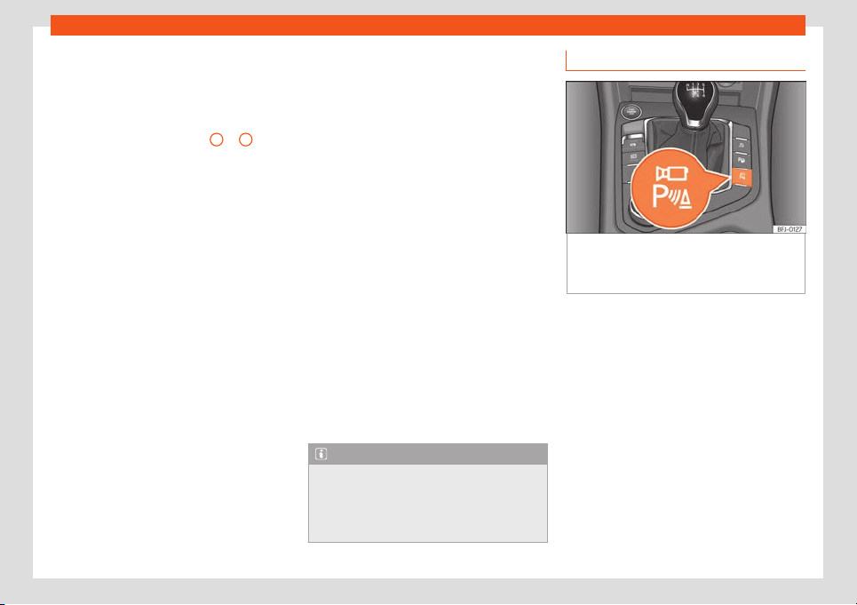
Help with parking and manoeuvring
The aerial view is generated by combining
the images fr
om all the camer
as
›
›
›
Fig. 295
. The aerial view can be selected
by pressing the vehicle in the area.
Select the corresponding view by pressing
the different areas
›››
Fig. 295
A
to
D
of the
aerial vie
w or the r
educed aerial vie
w
.
Conditions necessary f
or the use of the
Ar
ea Vie
w system
●
The doors and the rear lid must be closed.
●
The image must be reliable and clear. For
this reason, for example, the camera lens
must be clean.
●
The area around the vehicle must be clear-
ly and totally visible.
●
The area for parking or manoeuvring
should be a flat surface.
●
The vehicle should not be loaded very
heavily at the rear.
●
The driver must be used to the system.
●
There should be no damage to the vehicle
in the camera area. If the position or installa-
tion angle of the cameras have been
changed, e.g. after a rear-end collision, the
system should be checked by a specialised
workshop.
Special characteristics
The images on the area view system cameras
are only two-dimensional. Due to a lack of
spatial depth, it is difficult or impossible to
make out on-screen any holes there may be
on the ground, objects jutting out from the
ground or parts protruding from other vehi-
cles.
Situations in which the objects or other vehi-
cles appear to be further away or closer than
they really are:
●
On moving from a horizontal plane to a
slope.
●
On moving from a slope to a horizontal
plane.
●
If the vehicle is heavily loaded at the rear.
●
If the vehicle approaches protruding ob-
jects. These objects may be outside the cam-
eras' angle of visibility.
Trailer mode
The Area View system conceals, in the rear
camera area, all the auxiliary guiding lines
when the factory-fitted towing bracket is
connected electrically to a trailer
›››
page 332.
Note
In order to become familiar with the system
and its functions, SEAT recommends that
you practice handling the Area View sys-
tem in an area wher
e there is not too much
traffic or in a car park.
Connecting and disconnecting
Fig. 296
Centre console: button to manually
activ
at
e/deactiv
at
e the peripher
al vision sys-
t
em when combined with the park assist sys-
t
em.
Manual activation
●
Press button once
›
›
›
Fig. 296
.
The inf
ot
ainment syst
em screen displays the
aerial view
›››
Fig. 295. If you press the
button when driving at over 15 km/h (9 mph),
the image will not be displayed.
Automatic activation
●
Select reverse gear.
●
OR: The vehicle moves backwards.
The view of the image of the vehicle's rear
camera is shown in parallel parking mode
with the reduced aerial view.
»
325
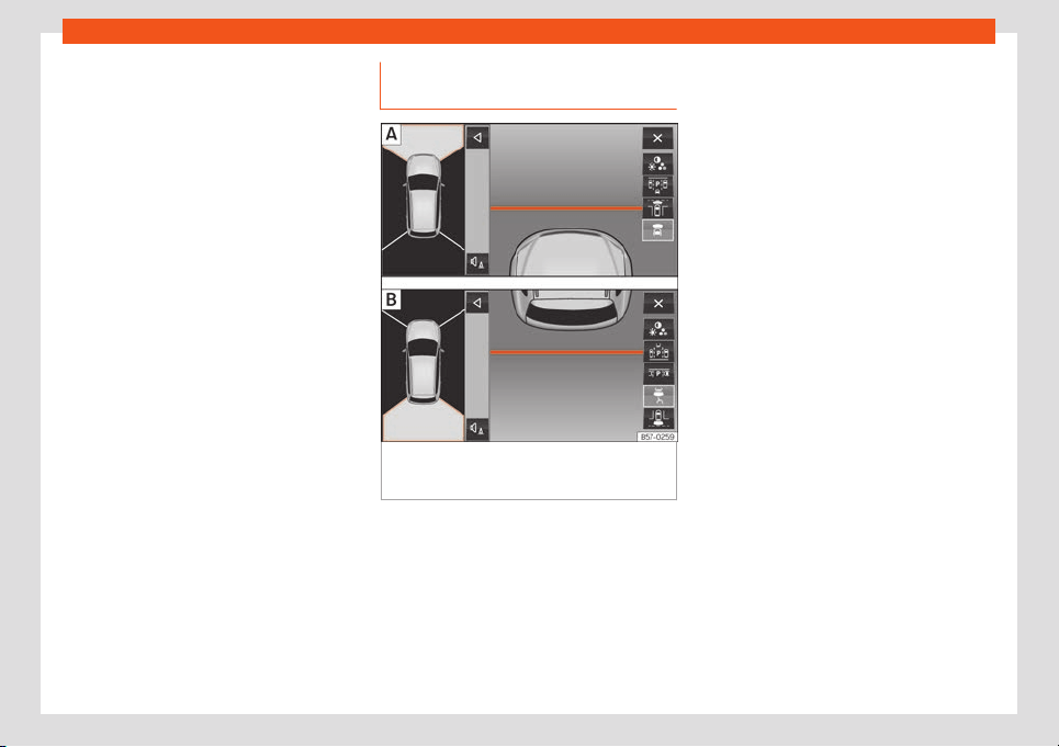
Driving
Manual disconnection
●
Press button again
›
›
›
Fig. 296
.
●
OR:
pr
ess a butt
on on the factory-equip-
ped infotainment system, for example the
button.
●
OR: press the function button.
Automatic off
●
Drive forwards at over 15 km/h (9 mph) ap-
proximately.
●
OR: switch off the ignition. The Area View
system menu disappears immediately.
Views of the peripheral vision sys-
tem (modes)
Fig. 297 Display on the top view system
scr
een: Fr
ont camer
a: off
-r
oad vie
w
. Rear
camera: off-road view.
Depending on the equipment: connect-
ing and disconnecting the P
arkPil
ot
sound.
Sho
wing the r
educed displ
ay.
Hiding the r
educed displ
ay.
Exiting the Area View system screen:
Adjust the display: bright, contrast and
colour.
The selected view is displayed on the right
side of the screen. The reduced aerial view
shown on the right side displays the view
framed in yellow. In addition, the right margin
of the screen displays the menu options pos-
sible and the views (the so-called “modes”)
of the camera in question. The active view
(mode) at the time is highlighted.
The reduced aerial view can be hidden by
pressing the symbol to thus display the se-
lected view full-screen.
The red lines are indicate a distance of ap-
prox. 40 cm away from the vehicle.
Aerial views (bird's eye view)
Main mode:
The vehicle and its immediate vicinity
seen from above are shown. Depending
on the equipment, the ParkPilot's path
may also be displayed.
Three-dimensional views:
The vehicle and its vicinity seen from
above are shown.
The vehicle and its vicinity seen from
above are shown obliquely.
The vehicle and its vicinity seen obli-
quely are shown.
326
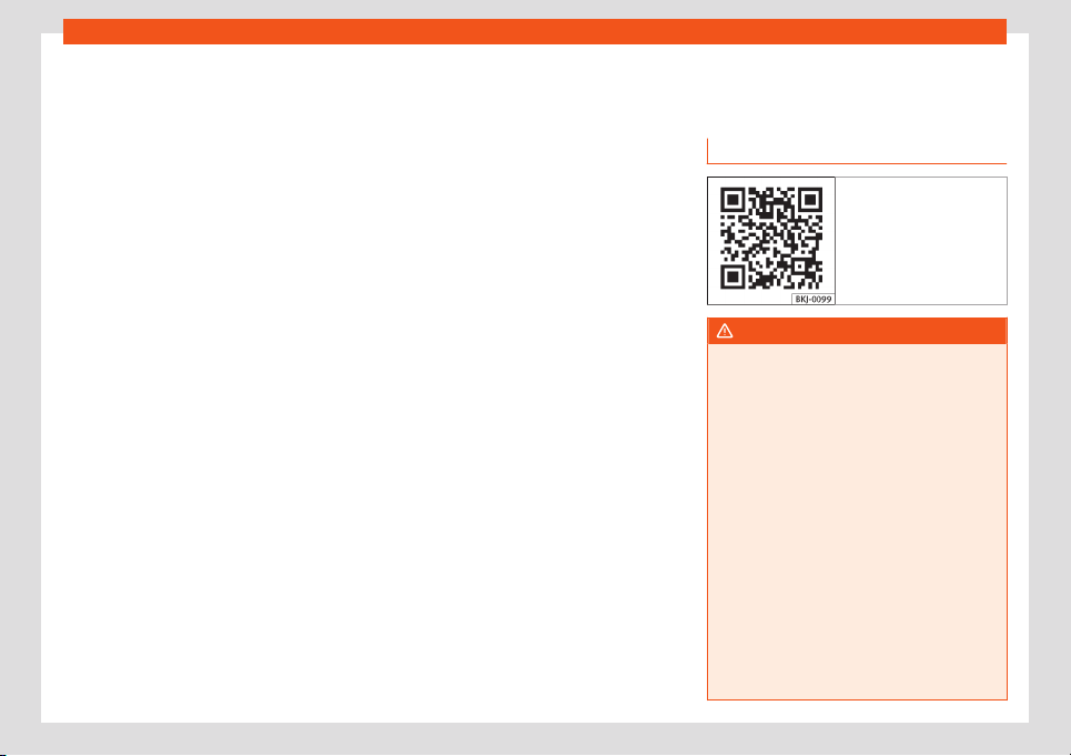
Help with parking and manoeuvring
Swipe the infotainment system display with
your finger in the dir
ection of the arr
o
ws t
o
change the angl
e of vision in the thr
ee-di-
mensional vie
ws of the vehicle and its vicinity.
Front camera views (front view)
Cross traffic. This visualization helps to
monitor traffic to the left, front and right
of the vehicle and can be used, for ex-
ample, when exiting garages or narrow
exits.
Angle parking. The area in front of the
vehicle is shown. Orientation lines are
shown to give guidance.
Off-road. The area directly in front of the
vehicle seen from above is shown. For
example, on a slope, in order to see the
area directly in front of the vehicle.
Side camera views (side view)
Right and left sides. The areas located
directly to the side of the vehicle seen
from above are represented in order to
navigate possible obstacles more pre-
cisely.
The driver’s or passenger's side seen
from above is shown. This makes it
possible to visualize the blind spots
along the vehicle.
Rear camera views (rear view)
Angle parking. The area behind the vehi-
cle is shown. Auxiliary lines are shown to
give guidance.
Parallel parking. The area directly be-
hind the vehicle is shown. The coloured
boxes and auxiliary lines serve as orien-
tation.
Off-road or hitching a trailer function.
The vehicle's rear is presented.
Green and red semicircular auxiliary
lines are displayed in vehicles with a fac-
tory-fitted towing bracket. The auxiliary
lines indicate the distance from the tow-
ing bracket. The distance between the
auxiliary lines (green and red) is approx.
30 cm The orange auxiliary line indi-
cates, according to how the steering
wheel is turned, the precalculated direc-
tion of the towed device.
Cross traffic. This visualization helps to
monitor traffic to the left, front and right
of the vehicle and can be used, for ex-
ample, when exiting garages or narrow
exits.
Reverse Assist (Rear View
Camera)*
Operating and safety warnings
Fig. 298 Related video
WARNING
●
The reverse assist does not make it possi-
ble to pr
ecisely calculate the distance from
obstacles and nor can it overcome the sys-
tem's own limits, hence its negligent use
may cause serious accidents and injuries if
used without due care. The driver should be
aware of his/her surroundings at all times
to ensure safe driving.
●
The camera lens expands and distorts
the field of view and displays the objects
on the screen in a way that is different from
reality. Distance perception is also distor-
ted.
●
Due to the screen resolution or light con-
ditions, some items may be blurry or not
displayed at all. Take care with thin posts,
fences, railings or trees that might not be
seen on the screen and could damage the
vehicle.
»
327
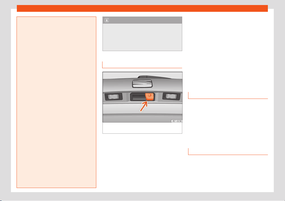
Driving
●
The reverse assist has blind spots where
it cannot see people or objects. Monit
or the
vehicle's surrounding area at all times.
●
Keep the camera lens clean, free of ice
and snow, and do not cover it.
●
The system is not a replacement for driv-
er awareness. Supervise the parking ma-
noeuvre and the vehicle's surrounding area
at all times.
●
Do not be distracted from the traffic by
looking at the screen.
●
The images are only two-dimensional.
Protruding objects or holes in the road, for
example, are more difficult to detect or
may not be seen at all.
●
Vehicle load modifies the representation
of the guide lines. The width represented
by the lines decreases with vehicle load.
Pay special attention to the surroundings
when the inside of the vehicle of the lug-
gage compartment are loaded.
●
In the following situations, objects or oth-
er vehicles appear to be further away or
closer than they actually are. Pay special
attention:
–
If moving from a flat surface to a slope
and vice-versa.
–
If the vehicle is heavily loaded.
–
When the vehicle approaches objects
that are not on the ground surface or
that protrude from it. These objects
may be outside the camera angle when
reversing.
Note
●
It is important to take great car
e and pay
special attention if the driver is not familiar
with the system.
●
The reverse assist reference lines disap-
pear when the rear lid is open.
Introduction
Fig. 299
In the rear lid handle: location of the
r
e
v
erse assist camer
a.
A camera installed in the rear lid handle as-
sists the driv
er with r
e
v
erse parking or ma-
noeuvring
›
›
›
Fig. 299.
The camera image is viewed together with
orientation lines projected on the Infotain-
ment system screen. Part of the bumper can
be seen at the bottom, which can be used by
the driver as a reference point.
Reverse assist modes
Depending on the equipment, the following
modes are available:
●
Angle parking: reverse parking perpendic-
ular to the road.
●
Parallel parking: reverse parking parallel
to the road.
●
Assistance function for hitching a trailer:
helps to hitch a trailer.
●
Cross traffic: traffic is monitored in a trans-
verse direction.
Connecting and disconnecting
Connect the reverse assist
●
Select reverse gear.
●
OR: pr
ess button .
Disconnect the r
e
v
erse assist
Driv
e f
orw
ard at least 15 km/h (9 mph).
Shown on the display
The system’s functions and representations
may v
ary depending on the equipment.
The assist
ant's image vie
w changes when the
f
act
ory-fitt
ed t
ow hitch is electronically con-
nected to a trailer
›››
page 339.
328

Help with parking and manoeuvring
Reverse assist functions and symbols
When the r
e
v
erse assist is connect
ed, you
can mak
e adjustments using the function but
-
t
ons. Some adjustments are equipment-de-
pendent.
Exit the current display
Switch to angle parking
›››
page 330
Switch to parallel parking
›››
page 330
Switch to the trailer hitching assistance
function
Switch to cross traffic
Adjust the display: brightness, contrast
and colour.
Switch to park assist
›››
page 314
Display the parking aid view
Hide the parking aid view
Turn the steering wheel (parallel park-
ing)
Stop the vehicle (parallel parking)
Guide lines
Green horizontal lines: extension of the vehi-
cle.
Red lateral line: when the steering wheel
needs to be turned the other way, a yellow
line turns red (parallel parking).
Yellow lines: vehicle path depending on the
steering angle.
Yellow auxiliary boxes: front and rear delimi-
tation of the parking space (parallel parking).
Green lateral line: point for turning the other
way when parking (parallel parking).
Red and green frame: outline of the vehicle
(parallel parking).
Assistance function for hitching a trailer
On vehicles with a factory-fitted towing de-
vice, this function can be used to move the
vehicle close to a tow bar. Due to the high
level of magnification of the image in this
mode, objects behind the vehicle are seen
very late.
Auxiliary lines are shown in the infotainment
system.
Red lines: position of the tow hitch.
Green lines: distance to the tow hitch. The
distance between the lines is approx. 0.1 m
Orange line: precalculated direction of the
tow hitch depending on steering wheel rota-
tion.
Cross traffic
This visualization helps to monitor traffic be-
hind the vehicle and can be used, for exam-
ple, when exiting garages or narrow exits.
Requirements
To park with reverse assist, the following re-
quirements must be met:
●
Do not exceed a speed of approx. 15 km/h
(9 mph)
.
●
Parking space width: vehicle width + 0.2 m
●
Distance: approx. 1 meter from the parking
space (parallel only).
●
Length of the parking space: approx. 8 m
(parallel only)
To display a real image, the following require-
ments must be met:
●
The luggage compartment rear door is
closed.
●
The surroundings are on a flat surface.
●
The v
ehicle should not be loaded very
heavily at the rear.
329
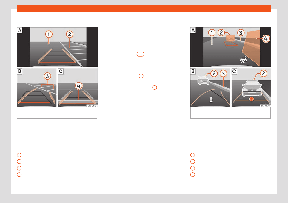
Driving
Parallel parking
Fig. 300 Display on the Infotainment system
scr
een.: parking with r
e
v
erse assist.
Key to the Fig. 300:
Finding a parking space
Go t
o the sel
ect
ed parking space
Centr
e the v
ehicl
e inside the parking
space
R
oad
Parking space
Lateral boundary of the parking space
Rear boundary of the parking space
1
2
3
4
Parking
●
Press the or butt
on bef
or
e passing in
fr
ont of the sel
ect
ed parking space
.
●
With reverse assist connected and in work-
ing order, press the function button .
●
Place the vehicle in front of the parking
space
›››
Fig. 300
two
.
●
Reverse while turning the steering wheel so
that the yell
o
w lines ent
er the parking space
.
The gr
een and yell
o
w lines must match the
side boundary lines
3
.
●
Stop the vehicle when the red line has
r
eached the r
ear boundary
4
.
Parallel parking
Fig. 301 Display on the Infotainment system
scr
een.: R
e
v
erse assist, mode 2.
Key to the Fig. 301:
Finding a parking space
Go t
o the sel
ect
ed parking space
Centr
e the v
ehicl
e inside the parking
space
R
oad
Obstacle or auxiliary box
Lateral boundary of the parking space
Obstacle or auxiliary box
1
2
3
4
330

Help with parking and manoeuvring
Parking
●
If necessary, press the butt
on bef
or
e
passing in fr
ont of the sel
ect
ed parking
space
.
●
With reverse assist connected and in work-
ing order, press the function button .
●
Turn on the corresponding turn signal on
the side of the road where you want to park.
●
Place the vehicle parallel to the parking
space, approx. 1 meter away.
●
If obstacles protrude from the auxiliary box-
es, find another parking space or realign the
vehicle.
●
Select reverse gear. A red frame represents
the target position of your vehicle.
●
Turn the steering wheel until the red frame
is between the auxiliary boxes and has
changed to green. Keep the steering wheel in
this position and start driving slowly.
●
When an arrow appears, reverse. A yellow
line and a green line appear. The arrow indi-
cates the distance that still has to be cov-
ered.
●
While reversing, keep the steering wheel in
the adjusted position. Adjust the steering
wheel rotation correctly when an indication
appears on the steering wheel symbol .
●
Reverse until the STOP signal is shown or
until the green line matches up with the later-
al boundary of the parking space.
●
Stop the vehicle. Turn the steering wheel as
far as it’ll go in the opposite direction.
●
Reverse until the STOP signal is shown or
until the red line reaches the rear boundary.
Problems and solutions
The system behaves differently than ex-
pected
There can be several causes:
●
The camera is dirt
y
›››
page 378. In addition
to dirt and sno
w, camera visibility can be re-
duced by detergent residue or any type of
coating.
●
The system requirements must be met
›››
page 329.
●
The camera is covered with water.
●
The factory-fitted towing bracket must not
be electrically connected to a trailer
›››
page 339.
●
The vehicle has some type of damage in
the camera area, e.g. due to a parking im-
pact.
●
The field of view of the camera is blocked
by an accessory, e.g. a bicycle carrier sys-
tem.
●
Changes have been made to the paint in
the camera area, or structural modifications
have been made to a component such as the
running gear.
Camera with no visibility, fault message,
the system disconnects
●
Clean the camera or remove possible ad-
hesives or accessories from it
›››
page 378.
●
Check for visible damage.
Possible solution
●
Temporarily disconnect the system.
●
Check if one of the causes indicated above
has occurred.
●
Once the source of the problem has been
eliminated, the system may be reconnected.
●
If the system still behaves unpredictably,
have it checked by a specialised workshop.
331
Driving
Towing bracket device*
T
r
ail
er mode
Intr
oduction
Take into account country-specific regula-
tions about driving with a trailer and the use
of a towing bracket.
The v
ehicle has been developed primarily for
carrying people, although it can also be used
to tow a trailer if fitted with the corresponding
technical equipment. This additional load has
an effect on the useful life, fuel consumption
and vehicle performance and in some cases
can reduce the service intervals.
Driving with a trailer requires more force from
the vehicle, and thus more concentration
from the driver.
In winter, winter tyres should be fitted on both
the vehicle and the trailer.
Maximum vertical load technically permit-
ted on the coupling device
The maximum technically permitted vertical
load of the trailer’s drawbar on the hitch of
the towing device is 100 kg.
Vehicles with the Start-Stop system
If the vehicle has a factory-fitted towing
bracket or one that is retrofitted by SEAT, the
Start-Stop system operates as normal. No
special characteristics need to be taken into
account.
If the syst
em does not recognise the trailer or
the trailer bracket has not been retrofitted by
SEAT, the Start-Stop system must be discon-
nected by pressing the corresponding button
in the lower part of the centre console before
driving with the trailer, and it should remain
off for the rest of the journey
›››
.
V
ehicl
es with driving pr
ofil
e sel
ection
If you ar
e going t
o be towing a trailer, the use
of the Eco driving profile is not recommen-
ded. You are advised to select another of the
available driving profiles before beginning to
drive with a trailer.
Trailer weight/drawbar load
Never exceed the authorised trailer weight. If
you do not load the trailer up to the maximum
permitted trailer weight, you can then climb
correspondingly steeper slopes.
The maximum trailer weights listed are only
applicable for altitudes up to 1000 m above
sea level. Since higher altitude decreases en-
gine performance and the ability to climb
slopes, the tow load decreases proportional-
ly. The weight of the vehicle and trailer com-
bination must be reduced by 10% for every
1000 m of altitude. When possible, operate
the trailer with the maximum authorised
drawbar load on the ball joint of the towing
bracket, but do not exceed the specified lim-
it.
WARNING
Never use the trailer to transport people,
since it would put their life in danger and is
also prohibited.
WARNING
Undue use of the towing bracket may
cause injury and accidents.
●
Only use the towing bracket if it is in a
perfect state of repair and is properly se-
cured.
●
Ne
ver modify or repair the towing bracket
in any way.
●
In order to reduce the danger of injury in
the event of rear-end collisions and to
avoid injury to pedestrians and cyclists
when parking the vehicle, cover or remove
the tow hook when you are not using a trail-
er.
●
Never fit a towing bracket “with weight
distribution” or “load compensation”. The
vehicle has not been designed for this type
of towing bracket. The towing bracket
could fail and the trailer could be released
from the vehicle.
332
Towing bracket device*
WARNING
Driving with a trailer and transporting
heavy or large objects can affect driving
properties and e
ven cause an accident.
●
Always secure the load properly using
belts or straps that are suitable and in
good condition.
●
Adapt your speed and driving style at all
times to suit visibility, weather, road and
traffic conditions.
●
Trailers with a high centre of gravity are
more likely to overturn than those with a
low one.
●
Avoid sudden braking and manoeuvres.
●
Take great care when overtaking.
●
Reduce speed immediately if you notice
that the trailer is swaying, however slightly.
●
Never drive at more than 80 km/h
(50 mph) when towing a trailer (or at more
than 100 km/h (60 mph) in exceptional cir-
cumstances). This also applies in countries
where driving at higher speeds is permit-
ted. Take into account the speed limit for
vehicles with trailers in the corresponding
country, as it could be less than the speed
limit for vehicles without a trailer.
●
Never attempt to “straighten” the towing
vehicle and trailer while accelerating.
WARNING
If the towing bracket has been retrofitted
by a non-SEAT workshop, the Start-Stop
system must be disconnected manually
whenever driving with a trailer. Otherwise
the brak
e system could be damaged and
could consequently cause a serious acci-
dent or injury.
●
Always disconnect the Start-Stop system
manually when using a towing bracket that
has not been fitted by a SEAT workshop.
Note
●
Bef
ore hitching or unhitching a trailer
, al-
ways deactivate the anti-theft alarm
›››
page 89. Otherwise, the tilt sensor could
cause the alarm to go off.
●
Do not drive with a trailer for the engine's
first 1000 km
›››
page 265.
●
SEAT recommends that, if possible, the
tow hook be removed or covered when it is
not going to be used. In the event of a rear-
end collision, the damage to the vehicle
could be greater if the tow hook is fitted.
●
Some retrofitted towing brackets cover
the rear towing eye. In these cases, the
towing eye should not be used for tow-
starting or for towing other vehicles. For
this reason, if the vehicle has been retrofit-
ted with a towing bracket, always keep the
tow hook in the vehicle when you remove it.
Technical requirements
Vehicles that are factory-fitted with a towing
br
acket meet all the technical and legal re-
quirements for driving with a trailer.
If the vehicle is retrofitted with a towing
bracket, only a bracket that is authorised for
the maximum authorised load of the trailer
that is to be towed may be fitted. The towing
bracket must be suitable for the vehicle and
the trailer and must be properly secured to
the vehicle's chassis. Only use a towing
bracket that has been authorised by SEAT for
this vehicle. Always check and take into ac-
count the towing bracket manufacturer's in-
structions. Never fit a towing bracket “with
weight distribution” or “load compensation”.
Towing bracket fitted on the bumper
Never fit a towing bracket to the bumper or to
the area where the bumper is mounted. The
towing bracket should not impair the bum-
per's function. Do not make modifications or
repairs to the exhaust system or the brake
system. Make regular checks to ensure that
the towing bracket is secure.
Engine cooling system
Driving with a trailer increases the load on the
engine and cooling system. The cooling sys-
tem should have sufficient coolant and be
prepared for the additional effort involved in
driving with a trailer.
»
333
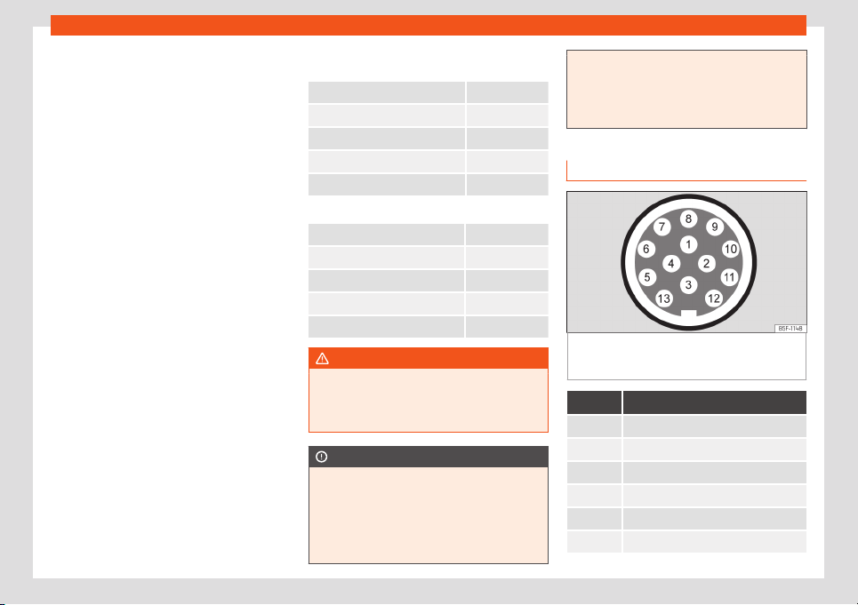
Driving
Trailer brakes
If the tr
ail
er has its o
wn br
ak
e syst
em, pl
ease
take the relevant legal requirements into ac-
count. Never connect the trailer's brake sys-
tem to the vehicle's brake system.
Tow cable
Always use a cable between the vehicle and
the trailer
›››
page 334.
Trailer tail lights
The trailer's rear lights should comply with
the statutory safety regulations
›››
page 334.
Never connect the trailer's rear lights directly
to the vehicle's electric system. If you are not
sure that the trailer's electrical connection is
correct, have it checked by a specialised
workshop. SEAT recommends visiting a SEAT
dealership for this.
Exterior mirrors
If you cannot see the area behind the trailer
with the exterior mirrors of the towing vehicle,
additional mirrors will have to be installed in
accordance with the regulations of the coun-
try in question. The exterior mirrors should be
adjusted before you start driving and must
provide a sufficient field of vision at the rear.
Trailer maximum electricity consumption
Never exceed the values indicated!
Europe, Asia, Africa, South America and Central
America
Brake lights (total) 84 Watts
Turn signal (on each side) 42 watts
Side lights (on each side) 50 Watts
Reverse lights (in total) 42 Watts
Rear fog light 42 Watts
Australia
Brake lights (total) 108 Watts
Turn signal (on each side) 54 Watts
Side lights (on each side) 100 Watts
Reverse lights (in total) 54 Watts
Rear fog light 54 Watts
WARNING
If the towing bracket is wrongly fitted or is
not the right one, the trailer could become
detached from the v
ehicle and cause seri-
ous injury.
CAUTION
●
If the rear lights of the trailer are not cor-
rectly connect
ed, the vehicle's electronic
system may be damaged.
●
If the trailer absorbs excessive electric
current, the vehicle's electronic system
may be damaged.
●
Never connect the trailer's electric sys-
t
em directly to the electrical connections
of the tail lights or any other power sour-
ces. Only use the connections intended for
providing electric current to the trailer.
Hitching and connecting a trailer
Fig. 302 Schematic representation: assign-
ment of the pins of the tr
ail
er
's el
ectrical sock
-
et.
Pin Meaning
1 Left turn signal
2 Rear fog light
3 Earth for pins 1, 2, 4, 5, 6, 7 and 8
4 Right turn signal
5 Rear light, right
6 Brake lights
334

Towing bracket device*
Pin Meaning
7 Rear light, left
8 Reverse lights
9 Permanent live
10 Live charge cable
11 Earth for pin 10
12 Unassigned
13 Earth for pin 9
Power socket for trailer
The v
ehicl
e is fitt
ed with a 13-pol
e po
w
er
sock
et for the connection between the trailer
and the vehicle. With the engine running,
electrical devices on the trailer receive power
from the electrical connection (pin 9 and pin
10 of the trailer power socket).
If the system detects that a trailer has been
connected, the consumers on the trailer will
receive electricity through this connection
(pins 9 and 10). Pin 9 has a permanent live.
This powers, for example, the trailer's interior
lighting. Electrical devices such as a fridge in
a caravan only receive electrical power if the
engine is running (through pin 10).
To avoid overloading the electrical system,
you cannot connect the ground wires of pin
3 , pin 11 or pin 13 to each other.
If the trailer has a 7-contact connector, you
will need to use an adapter cable. In this case
the function corresponding to pin 10 will not
be available.
Tow cable
The tow rope must always be securely fixed
to the towing vehicle and loose enough so
that the vehicle can handle turns smoothly.
However, make sure that the cable does not
rub on the ground while driving.
Trailer tail lights
Always check the trailer's rear lights to ensure
they are working correctly and that they
comply with the relevant safety regulations.
Make sure that the maximum permissible
power that can be absorbed by the trailer is
not exceeded
›››
page 334.
Include in the anti-theft alarm
The trailer is included in the anti-theft system
if the following conditions are met:
●
If the vehicle is factory-equipped with an
anti-theft alarm and towing bracket.
●
If the trailer is electrically connected to the
towing vehicle through the trailer power sock-
et.
●
If the electrical systems of the vehicle and
trailer are in perfect condition and have no
faults or damage.
●
If the vehicle is locked with the key and the
anti-theft alarm is activated.
When the vehicle is locked, the alarm is trig-
gered if the electrical connection with the
trailer is cut off.
Before hitching or unhitching a trailer, always
turn off the anti-theft alarm. Otherwise, the tilt
sensor could cause the alarm to go off.
Trailers with LED tail lights
For technical reasons, trailers fitted with LED
rear lights cannot be connected to the anti-
theft alarm system.
When the vehicle is locked, the alarm does
not go off when the electrical connection
with the trailer is cut if it has rear lights with
light-emitting diodes.
If the Eco driving profile was selected when
hitching the trailer, this will automatically
switch to the Normal profile. If the system
cannot detect the attached trailer or if the
towing bracket has been retrofitted by an au-
to repair shop other than SEAT, you must
manually select the Normal profile before
you start driving with a trailer attached. To re-
connect the Eco profile once the trailer has
been unhitched, switch the ignition off and
back on once.
»
335
Driving
WARNING
If the cables are improperly or incorrectly
connected, it may lead to an excessive
amount of curr
ent supplied to the trailer,
which can cause abnormalities in the entire
vehicle electronic system, as well as acci-
dents and serious injuries.
●
Ensure that any repairs that need to be
carried out on the electrical system are
carried out by a specialised workshop.
●
Never connect the trailer's electric sys-
tem directly to the electrical connections
of the tail lights or any other power sour-
ces.
WARNING
Contact between the pins of the trailer
power socket can cause short circuits,
ov
erloading of the electrical system or fail-
ure of the lighting system, and consequent-
ly can cause accidents and serious injuries.
●
Never connect the pins of the trailer pow-
er socket to each other.
●
Make sure any work on bent pins is car-
ried out by a specialised workshop.
CAUTION
Do not leave the trailer connected to the
vehicle when parked; place it on its support
wheel or its supports. If the v
ehicle rises or
falls due, for example, to a variation of the
load or a burst tyre, increased pressure will
be placed on the towing bracket and the
trailer, and both the vehicle and the trail
er
can be damaged.
Note
●
In case of anomalies in the el
ectrical sys-
tems of the vehicle or trailer
, as well as in
the anti-theft alarm system, have them in-
spected by a specialised workshop.
●
If the trailer accessories consume energy
through the power socket to the trailer and
the engine is turned off, the battery will dis-
charge.
●
If the vehicle battery is running low, the
electrical connection with the trailer will be
automatically cut.
Trailer loading
Technically permissible maximum trailer
w
eight and v
er
tical l
oad on the coupling
de
vice
The t
echnically permissibl
e maximum trailer
weight is the weight that the vehicle can tow
›››
. The vertical load on the coupling is ex-
ert
ed v
ertically fr
om abo
v
e on the hook of the
t
o
wing bracket.
The information on the maximum trailer
weight and vertical load on the coupling de-
vice contained in the type plate of the towing
bracket are experimental values only. The
correct figures for your specific model, which
may be lower than these figures, are given in
the vehicle documentation. The information in
the vehicle documentation takes precedence
at all times.
To promote safety while driving, SEAT recom-
mends making the most of the maximum ver-
tical load technically permissible on the
coupling device
›››
page 332. An insufficient
vertical load has a negative influence on the
behaviour of both the vehicle and trailer.
The vertical load increases the weight on the
rear axle, reducing the vehicle's carrying ca-
pacity.
Gross combination weight of the towing
vehicle and trailer
The gross combination weight is the actual
weight of the loaded vehicle plus the actual
weight of the loaded trailer.
In some countries trailers are classified into
distinct categories. SEAT recommends ob-
taining information from a specialised work-
shop regarding which type of trailer is most
suitable for your vehicle.
Trailer loading
The weight of the towing vehicle and trailer
must be balanced. In order to do this, the
load must be as close as possible to the max-
imum vertical load technically permissible on
the coupling point, and it must be evenly
336

Towing bracket device*
distributed between the back and front of the
tr
ail
er:
●
Distribut
e l
oads in the tr
ail
er so that heavy
ob
jects are as near to the axle as possible or
above it.
●
Secure the trailer load properly.
Tyre pressure
Set the tyre pressure of the trailer tyres in ac-
cordance with the trailer manufacturer's rec-
ommendations.
When towing a trailer, inflate the tyres of the
towing vehicle with the maximum allowable
pressure
›››
page 365.
WARNING
If the maximum permissible axle weight, the
maximum load technically permissible on
the coupling point, the maximum author-
ised vehicle w
eight or the gross combina-
tion weight of the towing vehicle and trailer
are exceeded, accidents and serious inju-
ries may occur.
●
Never exceed the values indicated!
●
The actual weight on the front and rear
axles must never exceed the maximum per-
missible axle weight. The weight on the
front and rear axles must never exceed the
maximum permissible weight.
WARNING
A shift in weight could jeopardize the stabil-
ity and security of the towing vehicle and
tr
ailer, which could lead to accidents and
serious injuries.
●
Always load the trailer correctly.
●
Always secure the load properly using
belts or straps that are suitable and in
good condition.
Driving with a trailer
Adjusting the headlights
The fr
ont part of the v
ehicl
e may be r
aised
when the tr
ail
er is connect
ed and the light
may dazzle the rest of the traffic.
Specific features of driving with a trailer
●
If your trailer has an overrun brake, brake
gently at first and then rapidly. This will pre-
vent the jerking that can be caused by the
locking of trailer wheels.
●
Due to the gross combination weight of the
towing vehicle and trailer, the braking dis-
tance increases.
●
When going down a slope, go into a lower
gear (if using a manual gearbox or the tip-
tronic automatic gearbox mode) to take ad-
vantage of the braking power provided by the
engine. Otherwise, the braking system could
overheat and even fail.
●
The trailer weight, as well as the gross com-
bination weight of the towing vehicle and
trailer, change the centre of gravity and the
properties of the vehicle.
●
If the towing vehicle is empty and the trailer
is loaded, then the load distribution is incor-
rect. Under these conditions, drive slowly and
with extra caution.
Hill starts with a trailer
Depending on the slope of the hill and the
combination weight of the towing vehicle and
trailer, the vehicle might start rolling back-
wards slightly when you first start up.
For hill-starting with a trailer, do the following:
●
Press and hold the brake pedal.
●
Press the button once to disconnect the
electronic parking brake
›››
page 299.
●
If the vehicle is equipped with a manual
gearbox, push the clutch pedal all the way
down.
●
Put the vehicle into first gear or turn the se-
lector lever to position D/S
›››
page 253.
●
Pull out the button and hold it in that po-
sition to immobilise the towing vehicle and
trailer with the electronic parking brake.
●
Release the brake pedal.
●
Start driving slowly. To do this, in the case of
a manual gearbox, slowly release the clutch
pedal.
»
337
Driving
●
Do not r
el
ease the
butt
on until the en-
gine has sufficient po
w
er t
o start driving.
WARNING
If a trailer is pulled incorrectly, this may
lead to loss of control of the vehicle and
serious injury.
●
Driving with a tr
ailer and transporting
heavy or large objects will change the ve-
hicle handling and braking distances.
●
Always drive cautiously and carefully.
Brake earlier than usual.
●
Adapt your speed and driving style at all
times to suit visibility, weather, road and
traffic conditions. Slow down, especially
when driving down hills or slopes.
●
Accelerate with particular care and cau-
tion. Avoid sudden braking and manoeu-
vres.
●
Take great care when overtaking. Reduce
speed immediately if you notice that the
trailer is swaying, however slightly.
●
Never attempt to “straighten” the towing
vehicle and trailer while accelerating.
●
Take into account the speed limit for vehi-
cles with a trailer, as it could be lower than
for vehicles without a trailer.
Stabilisation of the towing vehicle
and tr
ail
er combination
The stabilisation of the vehicle and trailer
combination is an additional function of the
electronic stability control (ESC).
If the vehicl
e and trailer stabilisation system
detects that the trailer is weaving, it takes ac-
tion on the steering control to reduce the
weaving of the trailer.
Vehicle and trailer combination stabilisa-
tion requirements
●
The vehicle is factory-equipped with a tow-
ing bracket or has been retro-fitted with a
compatible t
owing bracket.
●
The ESC and ASR are active. The control
lamp or is not lit up on the instrument
cluster.
●
The trailer is connected to the towing vehi-
cle through the trailer power socket.
●
The vehicle is travelling at over 60 km/h
(approx. 37 mph).
●
The maximum vertical load technically per-
missible is not being exceeded on the cou-
pling device.
●
The trailer has a rigid draw bar.
●
If the trailer has brakes, it must be equipped
with a mechanical overrun brake.
WARNING
The enhanced safety provided by the elec-
tric stability control of the vehicle and trail
-
er should not lead you to take any risks that
could compromise your safety.
●
Adapt your speed and driving style at all
times to suit visibility, weather, road and
traffic conditions.
●
Accelerate with caution when the road is
slippery.
●
When adjusting any settings, stop accel-
erating.
WARNING
The electric stability control for the vehicle
and trailer may not correctly detect all
driving conditions.
●
When the ESC is switched off
, the stabili-
sation of the towing vehicle and trailer is al-
so switched off.
●
The stability system does not always de-
tect light trailers, so it may not stabilise
these correctly.
●
When driving on surfaces with poor grip,
the trailer can even interfere with the sta-
bility system.
●
Trailers with a high centre of gravity can
tip over without having previously weaved.
●
If a trailer is not attached, but a connec-
tor is plugged into the power socket (e.g.
installation of a bicycle rack with lights),
338
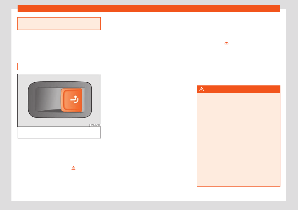
Towing bracket device*
repeated automatic braking may occur in
extreme driving conditions.
Electrically unlocking trailer
hook*
Description
Fig. 303
On the right side of the luggage com-
partment: butt
on f
or unl
ocking the t
o
w hook
.
The towing bracket’s hook is located in the
bumper
. T
o
w hooks f
or el
ectrical unl
ocking
cannot be r
emoved.
There should be no person, animal or object
in the path of the tow hook
›››
.
Unl
ocking the t
o
w hook and r
emo
ving it
●
St
op the v
ehicle and connect the electronic
parking brake
›››
page 299.
●
Switch off the engine.
●
Open the rear lid.
●
Pull the
›››
Fig. 303 button briefly. The tow
hook unlocks electrically and automatically
turns outwards. The button's control lamp
flashes.
●
Finish remove the tow hook by hand until
you feel and hear that it has engaged and
the control lamp on the button stays on.
●
Close the rear lid.
●
Hitching and connecting a trailer
›››
page 334.
Retracting the tow hook
●
Stop the vehicle and apply the electronic
parking brake.
●
Switch off the engine.
●
Unhook the trailer and interrupt the electri-
cal connection between it and the vehicle. If
you are using an adapter, remove it from the
trailer's power socket.
●
Open the rear lid.
●
Pull the
›››
Fig. 303 button briefly. The tow
hook unlocks electrically.
●
Turn the tow hook under the bumper with
your hand until you feel and hear that it en-
gages and the control lamp on the button re-
mains on continuously.
●
Close the rear lid.
The control lamp
●
If the warning light on the button
›››
Fig. 303 flashes, this means that the
tow hook has not been attached properly or
is damaged
›››
.
●
If the warning lamp
›
›
›
Fig. 303
r
emains
on with the rear lid open, the tow hook is cor-
rectly in place both when extracted and
when covered.
The control light of the lamp switches off ap-
proximately 1 minute after closing the read lid.
WARNING
Undue use of the towing bracket may
cause injury and accidents.
●
Only use the tow hook if it is properly en-
gaged.
●
Always ensure that no person, animal or
object is to be found in the path of the tow
hook.
●
Ne
ver use a tool or instrument while the
tow hook is moving.
●
Never press the
›››
Fig. 303 button when
there is a trailer hooked to the vehicle or
when a carrier system or other accessories
are mounted on the tow hook.
●
If the tow hook is not attached properly,
do not use it. Instead, go to a specialised
workshop and have the towing bracket
checked.
»
339
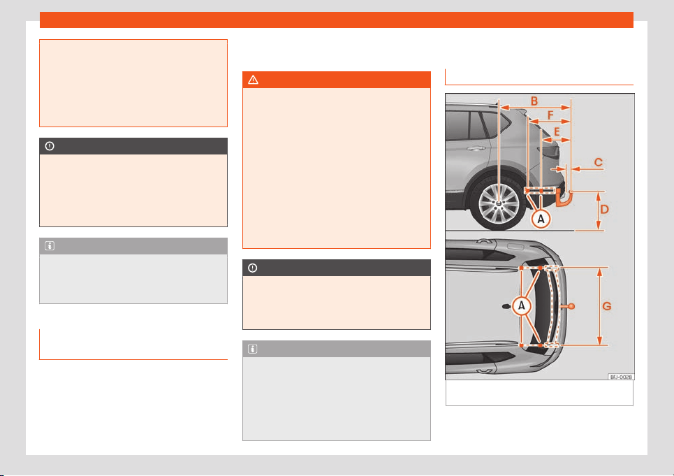
Driving
●
If you detect any fault in the electrical
system or in the towing br
acket, contact a
specialised workshop and ask them to
check it.
●
If the ball has a diameter of less than 49
mm at any one point, do not use the towing
bracket under any circumstances.
CAUTION
If you clean the vehicle with high-pressure
or st
eam devices, do not point the jet di-
rectly towar
ds the retractable tow hook or
the trailer power socket, as this may dam-
age the joints or remove the grease neces-
sary for lubrication.
Note
At extremely low temperatures, the tow
hook may be impossible to operate. In this
case, pl
ace the vehicle in a warmer loca-
tion (for example, a garage).
Fitting a bicycle carrier on the re-
tr
act
abl
e t
o
wbar
The maximum allowed weight of the carrier
syst
em, including the l
oad, is
75 k
g
. The carri-
er syst
em shoul
d not protrude more than 700
mm backwards from the spherical head. On-
ly carrier systems on which up to 3 bikes can
be mounted are allowed. Heavier bicycles
must be mounted as close to the vehicle as
possible (tow hook).
WARNING
The incorrect use of the tow hitch with a bi-
cycle rack mounted on the tow hook can
cause accidents and injury.
●
Nev
er exceed the maximum weight or the
limits indicated above.
●
The bicycle rack may not be mounted to
the neck of the hook below the ball be-
cause, due to the shape of the neck and
depending on the rack model, the rack
could be incorrectly mounted on the vehi-
cle.
●
Always read and take the manufacturer
assembly instructions into account.
CAUTION
If the maximum weight and limits indicated
above are exceeded, the vehicl
e may suf-
fer considerable damage.
●
Never exceed the values indicated!
Note
SEAT recommends removing, as far as pos-
sible, all removable par
ts of the bicycles
before setting off. These parts include, for
example, baskets and saddlebags, child
seats or batteries. This improves aerody-
namics and the centre of gravity of the rack
system.
Retrofitting a towing bracket
Description
Fig. 304
Limits and attachment points for ret-
r
ofitting a t
o
wing br
ack
et.
SEAT recommends that towing brackets be
r
etr
ofitt
ed at a specialised w
orkshop
. F
or
340
Towing bracket device*
example, it may very well be necessary to
adjust the cooling syst
em or mount thermal
pr
ot
ection pl
at
es. SEAT r
ecommends visiting
a SEAT deal
ership for this.
If a towing bracket is retrofitted, the distance
specifications should always be kept in mind.
The distance between the centre of the ball
head and the road
›››
Fig. 304
D
must never
be l
ess than indicat
ed. This al
so applies when
the v
ehicl
e is fully l
oaded, including the t
ech-
nically permissible maximum vertical load on
the coupling device.
Distance specifications
›››
Fig. 304:
Attachment points (lower part of the vehi-
cle)
1090 mm
65 mm min.
391 mm
348 mm
595 mm
1,050 mm
WARNING
If the cables are improperly or incorrectly
connected, this may lead to malfunctions
in the entire vehicle el
ectronic system, as
well as to accidents and serious injuries.
●
Never connect the trailer's electric sys-
tem to the electrical connections of the tail
lights or any other unsuitable power sour-
A
B
C
D
E
F
G
ces. Only use suitable connectors to con-
nect the trailer.
●
The towing brack
et should be retrofitted
only at a specialised workshop.
WARNING
If the towing bracket is badly fitted or un-
suit
able, the trailer may separat
e from the
vehicle while driving. This could cause seri-
ous accidents and fatal injuries.
Note
●
Only use towing brackets that have been
appro
ved by SEAT for the model in ques-
tion.
●
In some versions, the fitting of a conven-
tional towing hook solution is not recom-
mended. Please consult your Technical
Service.
341
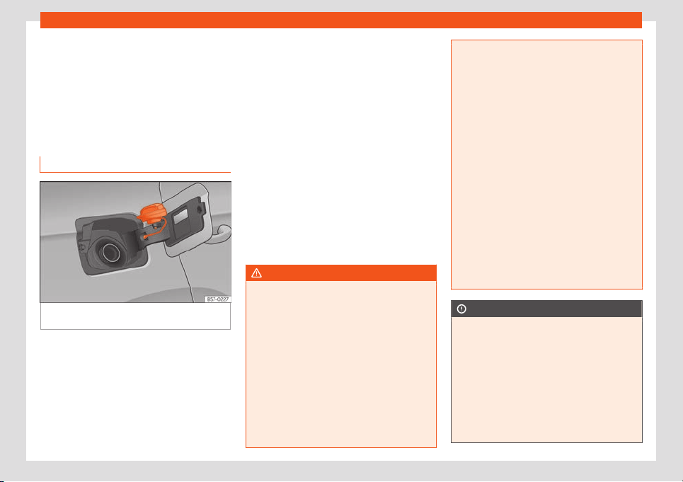
Practical tips
Practical tips
Checking and r
efilling l
e
v-
el
s
R
efuelling
R
efuelling
Fig. 305
Fuel tank flap with tank cap attach-
ed.
The fuel tank flap is on the rear right of the
v
ehicl
e
.
The fl
ap that co
v
ers the t
ank cap is unlocked
and locked automatically using the central
locking.
●
Open the fuel tank flap by pressing on the
left side.
●
Unscrew the cap by turning it to the left.
●
Place it in the space on the hinge of the
open flap
›››
Fig. 305.
●
Start refuelling. The tank is full as soon as
the pump’s automatic nozzle cuts off the fuel
supply. Do not try to put in more fuel after the
nozzle cuts out, as this will fill the expansion
chamber in the fuel tank.
●
Unscrew the cap by turning it to the right as
far as it will go.
●
Close the lid.
The correct fuel grade for your vehicle is giv-
en on a sticker on the inside of the fuel tank
flap. Further notes on fuel can be found at
›››
page 343.
The capacity of your vehicle's fuel tank is giv-
en in
›››
page 389.
WARNING
Fuel is highly flammable and can cause se-
rious burns and other injuries.
●
When refuelling, turn off the engine, the
auxiliary heater
›››
page 161 and turn off the
ignition f
or safety reasons.
●
Do not smoke when filling the fuel tank or
a canister. Naked flames are forbidden in
the vicinity due to the risk of explosion.
●
Observe legislation governing the use,
storage and carrying of a spare fuel canis-
ter in the vehicle.
●
For safety reasons we do not recommend
carrying a spare fuel canister in the vehi-
cle. In an accident the canister could be
damaged and could leak.
●
If, in exceptional cir
cumstances, you
have to carry a spare fuel canister, please
observe the following points:
–
Never fill fuel into the spare fuel canis-
ter if it is inside or on top of the vehicle.
This could cause an explosion. Always
place the canister on the ground to fill
it.
–
Insert the filling nozzle as far as possi-
ble into the spare fuel canister.
–
If the spare fuel canister is made of
metal, the filling nozzle must be in con-
tact with the canister during filling. This
helps prevent an electrostatic charge
building up.
–
Never spill fuel in the vehicle or in the
luggage compartment. Fuel vapour is
explosive. Risk of fatal accident!
CAUTION
●
If any fuel is spilt onto the vehicle, it
should be remo
ved immediately. It could
otherwise damage the paintwork.
●
Never run the tank completely dry. The
catalytic converter can be damaged.
●
When filling the fuel tank after having run
it completely dry on a vehicle with a diesel
engine, the ignition must be switched on for
at least 30 seconds before starting the en-
gine. When you then start the engine it may
342
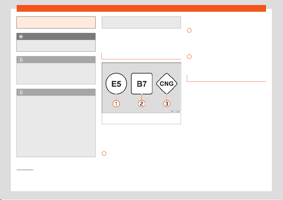
Checking and refilling levels
take longer than normal (up to one minute)
to start firing.
For the sake of the environment
Do not overfill the fuel tank, it may cause
the fuel t
o overflow if it becomes warm.
Note
There is no emergency mechanism for the
manual release of the fuel tank flap. If nec-
essary, request assist
ance from special-
ised personnel.
Note
Diesel vehicles are fitted with a protective
device that prevents the insertion of the
wrong fuel hose
1)
. It is only possibl
e to re-
fuel with Diesel nozzles.
●
If the pump nozzle is worn, damaged, or if
it is very small, it is possible that it will not
be able to open the protective device. Be-
fore trying to insert the pump nozzle by
turning it, try a different pump or request
specialist help.
●
If you fill the tank from a reserve fuel can-
ister, the protective device will not open.
One way to resolve this is to pour the fuel in
very slowly.
Fuel types
Identification of fuels
1)
Fig. 306
Identification of fuels according to
Eur
opean Union (EU) Dir
ectiv
e 2014/94/
Fuels are identified by different symbols on
the pump and on your v
ehicl
e's t
ank fl
ap
. The
identification serv
es t
o prevent confusion
when choosing the fuel.
Petrol with ethanol (“E” stands for Etha-
nol). The number indicates the percent-
1
age of ethanol in the petrol. “E5” means,
f
or e
x
ampl
e
, an ethanol r
atio of 5% max.
Diesel
with biodiesel (“B” stands for Bio-
diesel). The number indicates the per-
centage of biodiesel in the diesel. “B7”
means, for example, a proportion of bio-
diesel of max. 7%.
Natural gas: “CNG” means Compressed
Natural Gas.
Type of petrol
3 Valid for: vehicles with petrol engines
The correct grade of petrol is listed inside the
fuel t
ank flap.
The vehicle is equipped with a catalytic con-
verter and must only be run on unleaded
petrol. The petrol must comply with the
standard EN 228 and be sulphur-free. Fuels
with a 10% ethanol ratio can be refuelled
(E10)
2)
. The types of petrol are differentiated
by using the octane numbers (RON) or via
the anti-knock index (AKI).
»
2
3
1)
Depending on country
2)
Follow the regulations of the country you are
driving in.
343
Practical tips
Super unleaded petrol 95 octane petrol or
normal 91 oct
ane petr
ol at l
east
W
e r
ecommend r
efuelling with super 95 oc-
t
ane petrol (91 AKI). If not available, normal 91
octane petrol (87 AKI) (with a slight power
loss) may be used.
Super unleaded petrol, 95 octanes at
least
You should use super 95 octane petrol (91
AKI) at least.
If super is not available, if necessary, use nor-
mal 91 octane petrol (87 AKI). In this case only
use moderate engine speeds and a light
throttle. Refuel with super as soon as possi-
ble.
Unleaded super plus 98 octane petrol or
super 95 octane petrol at least
We recommend refuelling with super plus 98
octane petrol (93 AKI). If not available: super
95 octane petrol (91 AKI) (with a slight power
loss).
If super is not available, if necessary, use nor-
mal 91 octane petrol (87 AKI). In this case only
use moderate engine speeds and a light
throttle. Refuel with super as soon as possi-
ble.
CAUTION
●
Fuels high percentage of ethanol, e.g.
E30 - E100 button must not be used. The
fuel system w
ould be damaged. Exception:
vehicles with Totalflex engine
›››
page 344,
Ethanol fuel.
●
A single refuelling with leaded fuel or
other metal additives entails a permanent
deterioration of the effectiveness of the
catalytic converter.
●
Only use fuel additives that have been
approved by SEAT. The products that con-
tain substances to increase the octane rat-
ing or decrease knocking may contain met-
al additives that damage the engine and
catalytic converter. This type of products
must not be used.
●
Do not use fuels shown in the pump as
containing metals. LRP (lead replacement
petrol) fuels contain high concentrations of
metal additives. Risk of engine damage!
●
High engine speed and full throttle can
damage the engine when using petrol with
an octane rating lower than the correct
grade for the engine.
Note
●
Fuel with an octane rating higher than the
one required by the engine can be used.
●
In countries in which there is no sulphur-
free fuel, it is also allow
ed to use low sul-
phur content fuel.
Ethanol fuel
3 Valid for: vehicles with Totalflex engines
You can recognise vehicles with Tot
alflex en-
gines
1)
by label on the fuel tank lid with with
the marking “Petrol/ethanol”.
Vehicles with Totalflex engine can run with
unleaded petrol (95 octane / 91 AKI) accord-
ing to ANP No. 57 and with fuels with any high
percentage of ethanol. The vehicle is refuel-
led in the same way as petrol refuelling.
Also consider that
›››
page 343, Type of pet-
rol
Note
SEAT recommends filling the tank exclu-
sively with petrol every 10,000 km to de-
cr
ease impurities that using E100 ethanol
fuel might have left in the engine.
1)
This motor is only available in some markets.
344
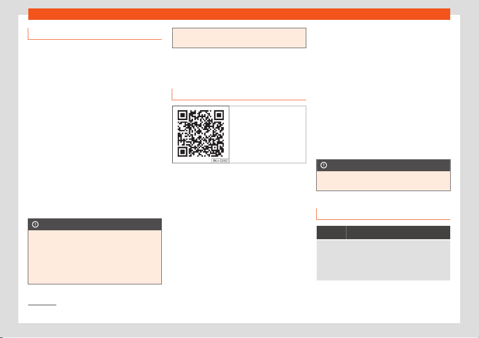
Checking and refilling levels
Diesel
3 Valid for: vehicles with diesel engines
Please note the information on the inside of
the fuel tank flap
.
We recommend you use Diesel according to
standard EN 590.
The diesel can thicken at very low tempera-
tures, thus affecting the start or operation of
the engine. Ask your service station attendant
if their diesel is suitable for winter use.
Water in the fuel filter
1)
If your vehicle has a diesel engine and is
equipped with a fuel filter with a water sep-
arator, the instrument panel may display the
following warning:
Water in the fuel
filter. If this is the case, take the vehicle to
a specialised workshop so that they can
drain the fuel filter.
CAUTION
●
Never use of FAME (biodiesel), petrol,
heating oil, other fuels or thinning agents
as they can cause sev
erely damage the
fuel system and the engine.
●
If the wrong fuel has been filled, do not
start the engine under any circumstances.
Risk of damaging the fuel system and the
engine! Obtain technical assistance.
AdBlue
®
Information about AdBlue
®
Fig. 307 Related video
The consumption of AdBlue
®
depends on
your personal driving st
yl
e
, the t
emper
at
ur
e
of the system and on the outdoor tempera-
ture when the vehicle is used.
AdBlue
®
freezes at temperatures of -11 °C (+13
°F). The system has heating elements that
guarantee its operation even at low tempera-
tures.
The capacity of the AdBlue
®
tank is approx.
18 litres.
When the range is less than 2400 km the
instrument panel screen displays a message
requesting an AdBlue
®
refill.
If this message is ignored, the yellow warning
lamp will come on when the remaining
range is less than 1000 km. The indication
that in XXX km it will no longer be possible to
restart the engine will appear on the instru-
ment panel display.
If the yellow indicator lamp is ignored, when
remaining range of 0 km is displayed, it will
no longer be possible to restart the engine.
The red warning lamp will light up.
AdBlue
®
is a registered brand of the German
Association of the Automotive Industry (VDA)
and is also known as AUS32 or DEF (Diesel
Exhaust Fluid).
CAUTION
Filling the AdBlue
®
tank excessively can
cause damage to the tank
.
Control and warning lamps
It lights up red
The engine cannot be restarted! The AdBlue level
is too low
.
Stop the vehicle in a suitable, safe and flat area then
top up with the minimum required quantity of AdBlue
›››
page 346.
»
1)
Depending upon country.
345
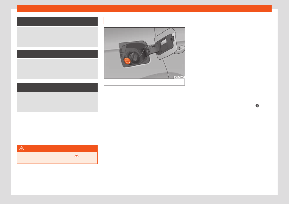
Practical tips
and
They light up red
The engine cannot be restarted! Fault in the
AdBlue system.
Contact a specialised workshop. Have the syst
em
checked there.
It lights up yellow
The AdBlue reserve is low.
Refill AdBlue within the next kilometres (or miles) that
are indicat
ed
›››
page 346. SEAT recommends con-
tacting a specialised workshop.
and
They light up yellow
There is a fault in the AdBlue system or unsuitable
AdBlue fluid has been used.
Contact a specialised workshop. Have the system
checked ther
e.
Several warning and control lamps should
light up f
or a f
e
w seconds when the ignition is
s
wit
ched on, signalling that the function is be-
ing v
erified. They will s
witch off after a few
seconds.
WARNING
Observe the safety warnings
›››
in Con-
trol and warning lamps on page 81.
Fill AdBlue
®
Fig. 308
AdBlue tank cap.
Operations prior to refilling
P
ark the v
ehicl
e on a fl
at surf
ace and t
urn off
the ignition. If the v
ehicle is on a slope or on a
curb, the level indicator may not detect the
refill properly.
If a warning message about AdBlue
®
levels
appears on the dash panel display, fill at
least the minimum amount required (ap-
prox. 5 litres) Only after adding this amount
will the system detect that AdBlue
®
has been
added and you will be able to start the en-
gine again. The maximum amount that can
be refilled is 11 litres.
Fill with a refill bottle
Only use AdBlue
®
that complies with ISO
22241-1. Only use original containers.
●
Open the tank cover
›››
Fig. 308.
●
Unscrew the tank cap by turning it in an an-
ti-clockwise direction.
●
Please observe the manufacturer's instruc-
tions, indicated on the refill bottle.
●
Check the expiry date.
●
Remove the cap of the refill bottle.
●
Insert the neck of the bottle in the tank filler
neck vertically and screw the bottle on by
hand, by turning it in a clockwise direction.
●
Press the refill bottle in the direction of the
filler neck and hold it in this position.
●
Wait until the contents of the refill bottle
have been poured into the AdBlue
®
tank. Do
not compress or break the bottle!
●
Turn the bottle in a counter-clockwise di-
rection and gently pull it upwards
›››
.
●
The AdBlue
®
t
ank is full when no mor
e liquid
comes out of the bottl
e
.
●
Scr
e
w on the t
ank cap in a clockwise direc-
tion until it is tightly closed.
●
Close the fuel tank flap.
Operations before driving
●
After refilling the tank, only switch on the ig-
nition.
●
Leave the ignition on for at least 30 sec-
onds for the system to detect the fluid load.
●
Make sure you wait for at least 30 seconds
before starting the engine!
346
Checking and refilling levels
Refilling the dispenser with AdBlue
V
alid f
or v
ehicl
es with sel
ectiv
e cat
alytic re-
duction.
●
Open the tank cap.
●
Turn the SCR tank cap anti-clockwise
›››
Fig. 308.
●
Add AdBlue until the nozzle stops for the
first time.
●
Close the SCR tube by turning it clockwise
until you hear a click.
WARNING
AdBlue
®
should only be stored in the origi-
nal container, which should be tightly
cl
osed and kept in a safe place.
CAUTION
●
When refilling, the nozzle grip should be
aligned downwar
d. Otherwise the nozzle
will not connect automatically.
●
Do not try to add any more additive after
the nozzle has stopped for the first time.
The AdBlue tank could overflow and AdBlue
could spill out.
●
Only use AdBlue
®
that complies with ISO
22241-1. Only use original containers.
●
Never mix AdBlue
®
with water, fuel or ad-
ditives. Any type of damage caused by
such a mixture will not be covered by the
warranty.
●
Never pour AdBlue
®
into the fuel tank.
This could r
esult in engine damage.
●
Do not carry the refill bottle inside the
vehicle. If there is a leak (due to tempera-
ture changes or damage to the bottle), the
AdBlue
®
may damage the vehicle.
For the sake of the environment
Dispose of the refill bottle in an environ-
ment
-friendly manner.
Note
You can buy refill bottles that are adequate
for AdBlue
®
use at SEAT dealerships .
Engine management and
emissions contr
ol syst
em
Intr
oduction
WARNING
●
Due to the high temperatures reached by
the e
xhaust gas scrubbing system, you
should not park your vehicle near a surface
that can catch fire easily. Fire hazard!
●
Do not apply wax underneath the vehicle
around the area of the exhaust system: Fire
hazard!
Control lamps
It lights up
Fault in the emission control system.
Reduce speed and drive carefully to the nearest spe-
cialised workshop to have the engine checked.
Flashes
Combustion failures that can damage the catalytic
converter.
Reduce speed and drive carefully t
o the nearest spe-
cialised workshop to have the engine checked.
It lights up
Particulate filter blocked
›››
page 348.
It lights up
Fault in the petrol engine management.
Have the engine checked as soon as possible by a
specialised workshop.
When the ignition is swit
ched on, the (Electronic
Power Control) lights up and shoul
d go off once the
engine has started.
It lights up
Diesel engine preheating system.
The engine can be started straight away when the
lamp swit
ches off.
»
347
Practical tips
Flashes
Fault in the diesel engine management.
Have the engine checked as soon as possible by a
specialised workshop.
Note
While the control lamps , , or are
on, there might be faults in the engine, fuel
consumption may go up and the engine
might lose pow
er.
Catalytic converter
To maintain the useful life of the catalytic
conv
er
t
er
●
Only use unl
eaded petr
ol with petr
ol en-
gines.
●
Ne
ver run the fuel tank dry.
●
When changing or adding engine oil, do not
exceed the necessary amount
›››
page 354,
Topping up the engine oil.
●
Never tow the vehicle to start it, use jump
leads if necessary
›››
page 51.
If you should notice misfiring, uneven running
or loss of power when the car is moving, have
the vehicle inspected by a specialised work-
shop. In general, the emissions warning lamp
will light up when any of these symptoms
occur. If this happens, any unburnt fuel can
enter the exhaust system and escape into the
atmosphere. The catalytic converter can also
be damaged by overheating.
CAUTION
Never run the fuel tank completely dry be-
cause an irregular fuel supply can cause
ignition faults. This allows unburnt fuel to
ent
er the exhaust system, which could
cause overheating and damage the cata-
lytic converter.
For the sake of the environment
Even when the emission control system is
working perfectly, there may be a smell of
sulphur from the gases on occasions. This
depends on the sulphur content of the fuel
used. This can quite oft
en be avoided by
changing to another brand of fuel.
Particulate filter
3 Valid for: vehicles with petrol or diesel particu-
late filters
The particulat
e filter eliminates most of the
soot from the exhaust gas system. Under nor-
mal driving conditions the filter cleans itself. If
the filter does not clean itself (e.g. if short
journeys are made continuously), it becomes
blocked with soot and the following indica-
tion is displayed to the driver: Particu-
late filter: cleaned while the vehi-
cle is moving. See Manual. The partic-
ulate filter needs cleaning (regeneration).
R
egeneration of the petrol particulate fil-
ter (only for 2.0l TSI engines)
Requirements for the regeneration journey:
the engine is at operating temperature.
●
Drive at a speed of at least 80 km/h
›››
●
Completely remove your foot from the ac-
cel
er
at
or pedal f
or a f
e
w seconds t
o let the
vehicle roll with the gear engaged.
●
Consider the legal speed limits as well as
the recommended gears.
●
Repeat this procedure (accelerate and let
roll) until the control lamp turns off.
This procedure involves an autonomous par-
ticulate filter cleaning process and may take
some time.
If the warning lamp does not turn off, go im-
mediately to a specialised workshop to repair
the fault.
Regeneration of the petrol (except the TSI
2.0l engine) and diesel particulate filter
Requirements for the regeneration journey:
the engine is at operating temperature.
●
Drive at a speed of between 50-120 km/h
(31-75 mph). This increases the temperature
and burns the soot in the filter
›››
.
348
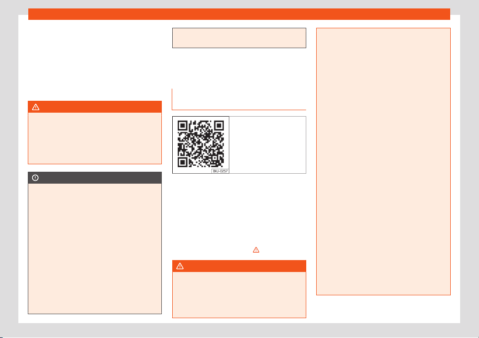
Checking and refilling levels
●
Consider the l
egal speed limits as w
ell as
the r
ecommended gears.
●
End the r
egener
ation journey once the con-
tr
ol w
arning lamp has gone out.
If the warning lamp stays on after 30 minutes
of running in regeneration mode, have a spe-
cialised workshop repair the fault
WARNING
Always adjust your speed to suit the weath-
er conditions, roads, braking distance and
traffic if the particulat
e filter is in its regen-
eration phase. Route recommendations
should never make you disregard each
country's specific traffic regulations.
CAUTION
●
When the exhaust system detects that
the particulate filt
er is close to saturation,
the self-cleaning function of this system
recommends optimal driving for this func-
tion.
●
Due to the high temperatures caused by
the regeneration of the particulate filter, it
is possible that the radiator fan will acti-
vate after stopping the engine, even it its
operating temperature has not been
reached.
●
Noise, smells and high idle speeds can
occur during regeneration.
●
Always use the correct engine oil and the
correct fuel to make sure the useful life of
the particulate filter is not affected. Also
avoid making short trips all the time.
Engine compartment
Working in the engine compart-
ment
Fig. 309 Related video
Always be aware of the danger of injury and
scal
ding as w
ell as the risk of accident or fir
e
when w
orking in the engine compartment
(e
.g. when checking and r
efilling fluids).
Al
ways observe the warnings listed below
and follow all general safety precautions.
The vehicle's engine compartment is a po-
tentially hazardous area
›››
.
WARNING
When work is done in the engine compart-
ment, injuries, burns, accidents and even
fires can occur.
●
Switch the engine off
, remove the key
from the ignition and apply the electronic
parking brake. If the vehicle has a manual
gearbox, place the lever in neutral; if it has
an aut
omatic gearbox, place the selector
lever in position P. Wait for the engine to
cool down.
●
Never open the bonnet if you see steam
or drips of coolant being released from the
engine compartment. Wait until no steam
or coolant can be seen before opening the
bonnet.
●
Keep children away from the engine
compartment.
●
Never spill liquids used for vehicle opera-
tion on the engine compartment, as these
may catch fire (e.g. the antifreeze in cool-
ant).
●
Avoid causing short-circuits in the elec-
trical system, particularly at the points
where the jump leads are attached
›››
page 51. The battery could explode.
●
If working inside the engine compart-
ment, remember that, even when the igni-
tion is switched off, the radiator fan may
start up automatically, and therefore there
is a risk of injury.
●
Never cover the engine with additional in-
sulating materials such as a blanket. Risk of
fire!
●
Do not unscrew the cap on the coolant
expansion tank when the engine is hot. The
cooling system is under pressure.
»
349
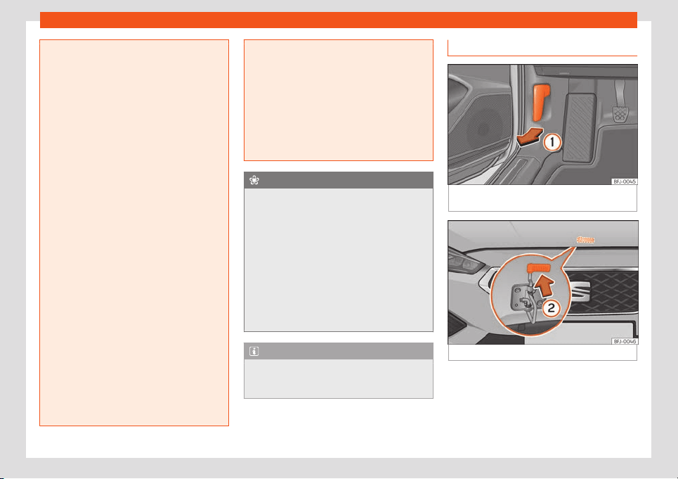
Practical tips
●
Protect face, hands and arms by cover
-
ing the cap with a large, thick rag to protect
against escaping coolant and steam.
●
Always make sure you have not left any
objects, such as cleaning cloths or tools, in
the engine compartment.
●
If you have to work underneath the vehi-
cle, you must use suitable stands addition-
ally to support the vehicle, there is a risk of
accident!. A hydraulic jack is insufficient for
securing the vehicle and there is a risk of
injury.
●
If any work has to be performed when the
engine is started or with the engine running,
there is an additional, potentially fatal,
safety risk from the rotating parts, such as
the drive belts, alternator, radiator fan, etc.,
and from the high-voltage ignition system.
You should also observe the following:
–
Never touch the electrical wiring of the
ignition system.
–
Ensure that jewellery, loose clothing
and long hair do not get trapped in ro-
tating engine parts. Danger of death.
Before starting any work remove jewel-
lery, tie back and cover hair, and wear
tight-fitting clothes.
–
Never accelerate with a gear engaged
without taking the necessary precau-
tions. The vehicle could move, even if
the handbrake is applied. Danger of
death.
●
Observe the following additional warn-
ings if work on the fuel syst
em or the elec-
trical system is necessary:
–
Always disconnect the battery from the
on-board network.
–
Do not smoke.
–
Never work near naked flames.
–
Always keep an approved fire extin-
guisher immediately available.
For the sake of the environment
●
Inspect the gr
ound underneath your vehi-
cle regularly so that any leaks ar
e detec-
ted at an early stage. If you find spots of oil
or other fluids in the area where it was
parked, have your vehicle inspected at the
workshop.
●
Service fluids leaks are harmful to the en-
vironment. For this reason you should make
regular checks on the ground underneath
your vehicle. If you find spots of oil or other
fluids, have your vehicle inspected in a
specialised workshop.
Note
In right-hand drive vehicles* some brake
fluid reservoirs are on the other side of the
engine compartment
›››
Fig. 312.
Opening and closing the bonnet
Fig. 310
Release lever in the driver's footwell
ar
ea.
Fig. 311
Cam under the bonnet
Opening the bonnet
The bonnet is r
el
eased fr
om inside the v
ehi-
cl
e
.
Bef
ore opening the bonnet, make sure that
the windscreen wiper arms are in place
against the windscreen.
350
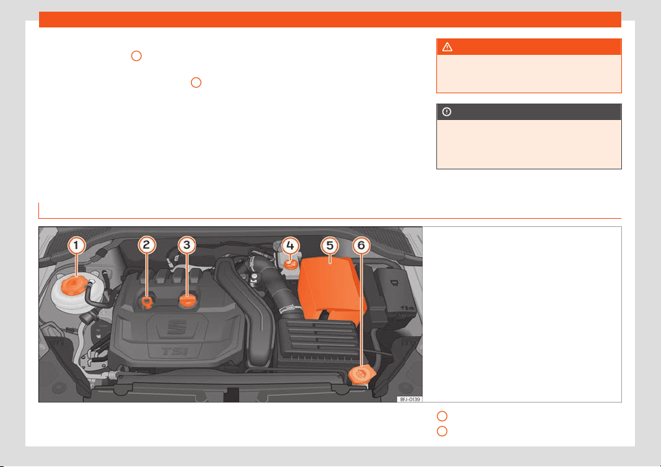
Checking and refilling levels
●
Open the door and pull the l
e
v
er under the
dashboar
d
›
›
›
Fig. 310
1
.
●
To lift the bonnet, press the release catch
under the bonnet up
w
ar
ds
›
›
›
Fig. 31
1
2
. The
arr
est
er hook under the bonnet is r
el
eased.
●
The bonnet can be opened. R
el
ease the
bonnet st
ay and secure it in the fixture de-
signed for this in the bonnet.
Closing the bonnet
●
Slightly lift the bonnet.
●
Release the bonnet stay and replace it in its
support.
●
At a height of approximately 30 cm let it fall
so it locks.
If the bonnet does not close, do not press
downwards. Open it again and let it fall as
mentioned above.
WARNING
Make sure that the bonnet is properly
closed. If it opens when driving, it can
cause an accident.
CAUTION
To avoid damage to the bonnet and to the
windscreen wiper arms, only open it when
the windscreen wipers are in place against
the windscreen.
Checking levels
Fig. 312
Diagram for the location of the various el-
ements.
From time to time, the levels of the different
fluids in the v
ehicl
e must be check
ed. Ne
v
er
fill with incorr
ect fluids, otherwise serious
damage t
o the engine may be caused.
Coolant expansion tank
›››
page 355
Engine oil level dipstick
›››
page 353
»
1
2
351

Practical tips
Engine oil filler cap
›
›
›
page 354
Br
ak
e fluid r
eserv
oir
›››
page 357
Battery (under the cover)
›››
page 358
Windscreen washer reservoir
›››
page 357
Note
The layout of parts may vary depending on
the engine.
Engine oil
Gener
al not
es
The engine comes with a special, multi-grade
oil that can be used all year r
ound.
Because the use of high-qualit
y oil is essen-
tial f
or the corr
ect oper
ation of the engine
and its l
ong useful lif
e, when topping up or
changing oil, use only those oils that comply
with VW standards.
We recommend that the oil change be done
by a technical service or specialised work-
shop.
If the engine oil level is too low
You can get information about the correct en-
gine oil for your vehicle at your workshop.
3
4
5
6
If the recommended engine oil is not availa-
bl
e
, in the e
v
ent of an
emer
gency
you can
change the oil once with a maximum of 0.5 L
of the next oil until the next oil change:
Petrol engines: standard VW 504 00,
VW 502 00, VW 508 00, ACEA C3 or
API SN.
Diesel engines: standard VW 507 00,
VW 505 01, ACEA C3 or API CK-4.
Have the oil changed by a specialised work-
shop.
Using engine oil that is compliant with the VW
504 00 standard instead of VW 508 00
could increase consumption and the vehicle’s
CO
2
emissions.
Recommended by SEAT
SEAT recommends using original SEAT oil to
guarantee high SEAT engine performance.
Vehicles with diesel particulate filter*
Only VW 507 00 engine oil, with reduced ash
formation, may be used in diesel engines
equipped with particulate filter. Using other
types of oil will cause a higher soot concen-
tration and reduce the life of the DPF. There-
fore:
●
Avoid mixing this oil with other engine oils.
–
–
●
Only in exceptional circumstances, if the
engine oil level is too low
›››
page 353 and
you cannot obtain the oil specified for your
vehicle, you can use a small quantity of oil
(once) conforming to the specifications
VW 506 00, VW 506 01, VW 505 00,
VW 505 01 or ACEA B3/ACEA B4 (up to 0.5 l)
›››
page 352.
Engine oil additives
No type of additive should be mixed with the
engine oil. The deterioration caused by these
additives is not covered by the warranty.
Note
Before a long trip, we recommend finding
an engine oil that conforms to the corre-
sponding VW specifications and recom-
mend keeping it in the vehicl
e. This way, the
correct engine oil will always be available
for a top-up if needed.
352
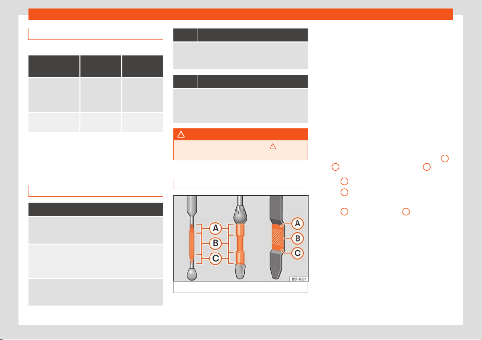
Checking and refilling levels
Engine oil specifications
Diesel engines
Engine type
Type of
Service
Specifica-
tion
With particulate
filter (DPF)
a)
Set Service
and Flexible
Service Inter-
vals
VW 507 00
Without particu-
late filter (DPF)
Set Service
Intervals
VW 505 01
b)
VW 506 01
b)
a)
Only use recommended oils, otherwise you may
damage the engine
.
b)
If the qualit
y of the fuel av
ail
abl
e in the country
does
not
fulfil the EN 590 (for diesel) standard.
Warning lamp
It lights up red
Do not carry on driving!
Engine oil pressure too low.
S
witch off the engine. Check the engine oil level.
If this warning lamp starts to flash, and is accom-
panied by three audible w
arnings, switch off the en-
gine and check the oil level. If necessary, add more
oil
›››
page 354.
If the warning lamp flashes although the oil level
is correct, st
op driving. Do not even run the engine at
idle speed! Obtain technical assistance.
It lights up yellow
Check the engine oil level as soon as possible.
Replace oil as soon as you have the opportunity to
do so
›
››
page 354.
It flashes yellow
Fault in the oil level sensor.
Have the check done by a specialised workshop. Un-
til then it is advisable to check the oil le
vel every time
you refuel.
WARNING
Observe the safety warnings
›››
in Con-
trol and warning lamps on page 81.
Checking the engine oil level
Fig. 313
Engine oil dipstick.
The engine oil dipstick indicates the level of
the oil.
Checking oil level
–
Park the vehicle in a horizontal position.
–
Briefly run the engine at idle speed until the
oper
ating t
emper
at
ur
e is r
eached and then
st
op.
–
Wait for about two minutes.
–
Pull out the dipstick. Wipe the dipstick with
a clean cloth and insert it again, pushing it
in as far as it will go.
–
Then pull it out once more and check the oil
level
›››
Fig. 313. Top up with engine oil if
necessary.
The oil must leave a mark between zones
A
and
C
. It can never go above zone
A
.
●
Zone
A
: do not add oil.
●
Zone
B
: you can add oil but keep the level
in that z
one
.
●
Z
one
C
: add oil until zone
B
.
Depending on ho
w you driv
e and the condi-
tions in which the v
ehicl
e is used, oil con-
sumption can be up t
o 0.5 l/1000 km. Oil
consumption is lik
ely t
o be higher for the first
5,000 km. For this reason the engine oil level
must be checked at regular intervals, prefera-
bly when filling the tank and before a journey.
»
353
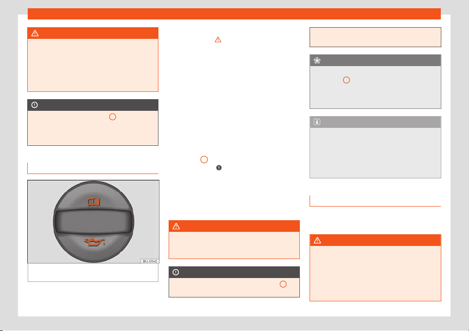
Practical tips
WARNING
Any work carried out in the engine com-
partment or on the engine must be carried
out cautiously.
●
When working in the engine compart-
ment, always observ
e the safety warnings
›››
page 349.
CAUTION
If the oil level is above area
A
, do not start
the engine. This could result in damage to
the engine and catalytic conver
ter. Con-
tact a Technical Service.
Topping up the engine oil
Fig. 314 In the engine compartment: Engine oil
fill
er cap
.
Before opening the bonnet, read and observe
the w
arnings
›
›
›
in Working in the engine
compar
tment on page 349
.
T
opping up engine oil
●
Unscr
e
w cap fr
om engine oil fill
er opening
›››
Fig. 314.
●
Carefully add oil in small quantities (no
more than 0.5 l).
●
To avoid adding too much oil, whenever you
add a certain amount, wait about 2 minutes
and recheck the oil level
›››
page 353.
●
If necessary, add some more oil.
●
When the oil level reaches at least zone
›››
Fig. 313
B
, unscrew the engine oil filler
cap car
efully
›
›
›
.
The position of the oil fill
er opening is sho
wn
in the corr
esponding engine compartment il
-
lustr
ation
›
›
›
page 351.
Engine oil specification
›››
page 353.
WARNING
Oil is highly inflammable! Ensure that no oil
comes into contact with hot engine compo-
nents when topping up.
CAUTION
If the oil level is above area
›››
Fig. 313
A
,
do not start the engine. This could result in
damage to the engine and catalytic con-
verter. Contact a specialised workshop
.
For the sake of the environment
The oil level must never be above zone
›
››
Fig. 313
A
. Otherwise oil can be drawn in
through the crankcase breather and leak
into the atmospher
e via the exhaust sys-
tem.
Note
Before a long trip, we recommend finding
an engine oil that conforms to the corre-
sponding VW specifications and recom-
mend keeping it in the vehicl
e. This way, the
correct engine oil will always be available
for a top-up if needed.
Engine oil change
We recommend that you have the engine oil
changed by a T
echnical Service
.
WARNING
Only change the engine oil yourself if you
have the specialist knowledge required!
●
Befor
e opening the bonnet, read and ob-
serve the warnings
›››
page 349.
●
Wait for the engine to cool down. Hot oil
may cause burn injuries.
354
Checking and refilling levels
●
Wear eye protection to avoid injuries,
such as acid burns, caused by splashes of
oil.
●
When r
emoving the oil drain plug with
your fingers, keep your arm horizontal to
help prevent oil from running down your
arm.
●
Wash your skin thoroughly if it comes into
contact with engine oil.
●
Engine oil is poisonous! Used oil must be
stored in a safe place out of the reach of
children.
CAUTION
No additives should be used with engine oil.
This could result in engine damage. Any
damage caused by the use of such addi-
tives would not be co
vered by the factory
warranty.
For the sake of the environment
●
We recommend that you change the en-
gine oil and the filter at a technical service
centre.
●
Ne
ver pour oil down drains or into the
ground.
●
Use a suitable container when draining
the used oil. It must be large enough to hold
all the engine oil.
Cooling system
Cool
ant specifications
The engine cooling system is supplied from
the factory with a specially treated mixture of
w
ater and at least 40 % of the additive
G12evo (TL-VW 774 J), purple. This mixture
gives the necessary frost protection down to
-25°C (-13°F) and protects the light alloy
parts of the engine cooling system against
corrosion. It also prevents scaling and con-
siderably raises the boiling point of the cool-
ant.
To protect the cooling system, the percent-
age of additive must always be at least 40 %,
even in warm climates where anti-freeze pro-
tection is not required.
If for weather reasons further protection is
necessary, the proportion of additive may be
increased, but only up to 60 %; otherwise an-
tifreeze protection will diminish and this will
worsen cooling.
When the coolant is topped up, use a mixture
of distilled water and at least 40 % of the
additive G12evo for optimal protection
against corrosion. Mixing G12evo with G13
(TL-VW 774 J), G12 plus-plus (TL-VW 774 G),
G12 plus (TL-VW 774 F), G12 (red) or G11
(green blue) engine coolants decreases pro-
tection again corrosion and should be avoi-
ded.
WARNING
If there is not enough anti-freeze in the
coolant system, the engine may fail lead-
ing to serious damage.
●
Ensur
e that the percentage of additive is
correct for the lowest expected ambient
temperature in the zone in which the vehi-
cle is to be used.
●
When the outside temperature is very
low, the coolant could freeze and the vehi-
cle would be immobilised.
CAUTION
The original additives should never be
mixed with coolants which are not ap-
proved by SEAT
.
●
If the fluid in the expansion tank is not
purple but is, for example, brown, this indi-
cates that the G12evo additive has been
mixed with an inadequate coolant. The
coolant must be changed as soon as possi-
ble if this is the case!
For the sake of the environment
Coolants and additives can contaminate
the environment. If any fluids are spilled,
they should be collected and corr
ectly dis-
posed of, with respect to the environment.
355
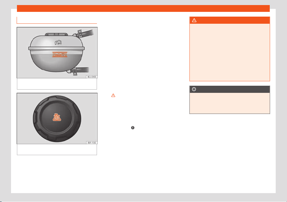
Practical tips
Refilling coolant
Fig. 315
In the engine compartment: marking
on cool
ant e
xpansion t
ank
.
Fig. 316
Engine compartment: coolant expan-
sion t
ank cap
.
The coolant tank is located in the engine
compartment
›
›
›
page 351
.
T
op up cool
ant when the l
evel is below the
(minimum) mark.
Checking coolant level
–
Park the vehicle in a horizontal position.
–
Switch the ignition off.
–
Read off the coolant level on coolant ex-
pansion tank. When the engine is cold, the
coolant level should be between the marks
›››
Fig. 315. When the engine is hot, it may
be slightly above the upper mark.
Topping up coolant
–
Wait for the engine to cool down.
–
Cover the coolant expansion tank cap with
a cloth and carefully unscrew it to the left
›››
.
–
Top up the coolant only if there is still cool-
ant in the e
xpansion t
ank
, otherwise you
coul
d
damage the engine
. If ther
e is no
coolant in the expansion tank, do not con-
tinue driving. You should obtain professional
assistance
›››
.
–
If there is still some coolant in the expansion
t
ank
, t
op up t
o the upper mark
.
–
T
op up with cool
ant until the level becomes
stable.
–
Screw the cap back on correctly.
If there is a coolant leak, take the vehicle spe-
cialised workshop to have the cooling system
examined.
WARNING
●
The cooling system is under pressure. Do
not unscrew the cap on the cool
ant expan-
sion tank when the engine is hot: risk of
burns!
●
Store the antifreeze in its original con-
tainer and keep it out of reach of children.
●
If working inside the engine compart-
ment, remember that, even when the igni-
tion is switched off, the radiator fan may
start up automatically, and therefore there
is a risk of injury.
CAUTION
If you run out of coolant in the expansion
tank, park the car in a safe place and do
not continue driving. Obtain technical as-
sist
ance.
356
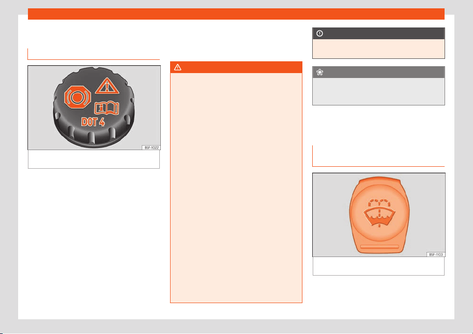
Checking and refilling levels
Brake fluid
Check and r
efill the br
ak
e fluid
Fig. 317
Engine compartment: brake fluid res-
erv
oir cap
.
The brake fluid reservoir is located in the en-
gine compartment
›
›
›
page 351
.
Checking the br
ak
e fluid l
evel
The brake fluid level must be between the
and markings.
However, if the brake fluid level goes down
noticeably in a short time, or drops below the
mark, there may be a leak in the brake
system. Seek specialist assistance. A warning
light on the instrument panel display monitors
the brake fluid level
›››
page 79.
In right-hand drive vehicles the brake fluid
reservoir is on the other side of the engine
compartment.
Changing brake fluid
We recommend that you have the brake fluid
changed by a Technical Service.
WARNING
If the brake fluid level is low or unsuita-
ble/old brake fluid is used, the brake sys-
t
em may fail or braking power may be re-
duced.
●
Check the brake system and the brake
fluid level regularly!
●
When the brake fluid is used and brakes
are subjected to extreme braking forces,
bubbles of vapour form in the brake sys-
tem. These bubbles can significantly re-
duce braking power, notably increasing
braking distance, and could result in the to-
tal failure of the brake system.
●
Be sure to always use the correct brake
fluid. Only use brake fluid that expressly
meets the VW 501 14 standard.
●
You can buy VW 501 14 standard brake
fluid in a SEAT dealership or a SEAT Official
Service. If none is available, use only high-
quality brake fluid that meets DIN ISO 4925
CLASS 4 standards, or USA Standards
FMVSS 116 DOT 4.
●
The replacement brake fluid must be
new.
●
Brake fluid should be stored in the closed
original container in a safe place out of
reach of children. Risk of poisoning!
CAUTION
Brake fluid should not come into contact
with the vehicle paintwork, as it is abrasive
.
For the sake of the environment
Brake fluid is an environmental pollutant.
Collect any spilt service fluids and allow a
professional to dispose of them.
Windscreen washer reservoir
Checking the l
e
v
el of the windo
w
w
asher t
ank and r
efilling it
Fig. 318 In the engine compartment: window
w
asher t
ank cap
.
The window washer tank is in the engine
compartment
›
›
›
page 351
.
»
357

Practical tips
Check the water level in the windscreen
w
asher r
eserv
oir r
egul
arly and t
op up as r
e-
quired.
The window washer tank contains liquid de-
tergent for the windscreen and rear window.
●
Open the bonnet
›››
page 349.
●
The window washer tank is marked with the
symbol on the cap.
●
Check there is enough windscreen water in
the reservoir.
Plain water is not enough to clean the wind-
screen and headlights. We recommend that
you always add a product to the windscreen
washer fluid.
Recommended windscreen wipers
●
For the hottest seasons we recommend
summer G 052 184 A1 for clear glass. Propor-
tions of the mixture in the washer fluid tank:
1:100 (1 part concentrate per 100 parts wa-
ter).
●
All year round, G 052 164 A2 for clear glass.
Approximate proportion of the winter mixture,
up to -18°C (0°F): 1:2 (1 part concentrate per 2
parts water); otherwise, a 1:4 proportion of
mixture in the washer fluid tank.
The capacity of the window washer tank can
be found in
›››
page 389.
CAUTION
If the water from the windscreen washer
does not contain enough anti-freeze, it may
free
ze on the windscreen and rear window,
reducing forward and rear visibility.
●
In winter, ensure the windscreen washer
contains enough anti-freeze.
●
In cold conditions, you should not use the
windscreen wiper system unless you have
warmed the windscreen with the ventila-
tion system. The antifreeze could freeze on
the windscreen and reduce visibility.
CAUTION
Never mix an unsuitable antifreeze or other
similar additives with the windscreen wash-
er water
. A greasy layer may be formed on
the windscreen which will impair visibility.
●
Use clean water with a window cleaner
recommended by SEAT.
●
If necessary, add a suitable antifreeze to
the water in the reservoir.
CAUTION
●
Do not mix cleaning products recommen-
ded by SEAT with other products. This
could lead t
o flocculation and may block
the windscreen washer jets.
●
When topping up service fluids, make ab-
solutely certain that you fill the fluids into
the correct reservoirs. Using the wrong flu-
ids could cause serious malfunctions and
engine damage!
●
Lack of window washer fluid causes the
view through the windscreen to be ob-
scured.
Battery
General information
The battery is located in the engine compart-
ment and is almost maint
enance-fr
ee
. It is
check
ed as part of the Inspection Service
.
Ne
v
ertheless, check the terminals are clean
and have the correct tightening torque, espe-
cially in summer and winter.
All work on batteries requires specialist
knowledge. Please refer to a SEAT Official
Service or a workshop specialising in batter-
ies: risk of burns or exploding battery!
The battery must not be opened. Never try
to change the fluid level of the battery. Oth-
erwise explosive gas is released from the bat-
tery that could cause an explosion.
Battery warning indications
Wear eye protection.
Battery acid is extremely corrosive. Wear pro-
tective gloves and eye prot
ection. Rinse any
splashes of electrolyte with plenty of water.
358
Checking and refilling levels
Fires, sparks, open flames and smoking are
prohibited.
The battery should only be charged in a well
-
ventilated zone. Risk of expl
osion!
Keep children away from acid and batteries!
Disconnecting the battery
The battery should only be disconnected in
exceptional cases. When the battery is dis-
connect
ed, some of the vehicle's functions
are lost. These functions will require resetting
after the battery is reconnected.
When disconnecting the battery from the ve-
hicle on-board network, disconnect first the
negative cable and then the positive cable.
Deactivate the anti-theft alarm* before you
disconnect the battery Otherwise the alarm
will be triggered.
If the vehicle is not used for long periods
The vehicle has a system for monitoring the
current consumption when the engine is left
unused for long periods of time
›››
page 361.
Some functions, such as the interior lights, or
the remote door opening, may be temporarily
disabled to prevent the battery from running
flat. These functions will come back on as
soon as the ignition is switched on and the
engine started.
Winter conditions
During the winter, the starting power may be
reduced, and if necessary, the batt
ery should
be charged
›››
WARNING
Always be aware of the danger of injury
and chemical burns as well as the risk of
accident or fire when working on the bat-
tery and the electrical syst
em:
●
Wear eye protection. Protect your eyes,
skin and clothing from acid and particles
containing lead.
●
Battery acid is extremely corrosive. Wear
protective gloves and eye protection. Do
not tilt the batteries. This could spill acid
through the vents.
●
Neutralise any electrolyte splashes on
the skin, eyes or clothing with a soapy solu-
tion, and rinse off with plenty of water. If
acid is swallowed by mistake, consult a
doctor immediately.
●
Fires, sparks, open flames and smoking
are prohibited. When handling cables and
electrical equipment, avoid causing sparks
and electrostatic charge. Never short the
battery terminals. High-energy sparks can
cause injury.
●
A highly explosive mixture of gases is re-
leased when the battery is under charge.
The batteries should be charged in a well-
ventilated room only.
●
Keep children away from acid and bat-
t
eries.
●
Before working on the electrical system,
you must switch off the engine, the ignition
and all electrical devices. The negative ca-
ble on the battery must be disconnected.
When a light bulb is changed, you need on-
ly switch off the light.
●
Deactivate the anti-theft alarm by un-
locking the vehicle before you disconnect
the battery! The alarm will otherwise be
triggered.
●
When disconnecting the battery from the
vehicle on-board network, disconnect first
the negative cable and then the positive
cable.
●
Switch off all electrical devices before
reconnecting the battery. Reconnect first
the positive cable and then the negative
cable. Never reverse the polarity of the
connections. This could cause an electrical
fire.
●
Never charge a frozen battery, or one
which has thawed. This could result in ex-
plosions and chemical burns. Always re-
place a battery which has frozen. A flat
battery can also freeze at temperatures
close to 0°C (+32°F).
●
Ensure that the vent hose is always con-
nected to the battery.
●
Never use a defective battery. This could
cause an explosion. Replace a damaged
battery immediately.
»
359
Practical tips
CAUTION
●
Do not expose the battery to direct sun-
light over a l
ong period of time, as the in-
tense ultraviolet radiation can damage the
battery housing.
●
If the vehicle is left standing in cold con-
ditions for a long period, protect the bat-
tery from “freezing”. If it freezes it will be
damaged.
Warning lamp
It lights up
Alternator fault.
The control lamp lights up when the ignition is
s
wit
ched on. It shoul
d go out when the engine
has st
art
ed running.
If the contr
ol l
amp lights up while driving,
the alternator is no longer charging the bat-
tery. You should immediately drive to the
nearest specialised workshop.
You should avoid using electrical equipment
that is not absolutely necessary because this
will drain the battery.
Checking the battery electrolyte
level
The electrolyte level should be checked reg-
ularly in high-mileage vehicles, in hot coun-
tries and in older batteries.
●
Open the bonnet and then lift the co
ver
that protects the front part of the battery
›››
in Working in the engine compart-
ment on page 349.
●
Check the colour display in the "magic eye"
on the top of the battery.
●
If there are air bubbles in the window
, tap
the window gently until they disperse.
The position of the battery is shown in the
corresponding engine compartment diagram
›
››
page 351.
The “magic eye” indicator, located on the top
of the battery changes colour, depending on
the charge state and electrolyte level of the
battery.
There are two different colours:
●
Black: correct charge status.
●
Transparent/light yellow: the battery must
be replaced. Contact a specialised work-
shop.
Charging or changing the battery
If you often drive short distances or if the ve-
hicle is not driven for long periods, the battery
should be check
ed by a specialised work-
shop between the scheduled services.
If the battery has discharged and you have
problems starting the vehicle, the battery
might be damaged. If this happens, we rec-
ommend you have the vehicle battery
checked by a Technical Service where it will
be re-charged or replaced.
Charging the battery
The vehicle battery should be charged by a
specialised workshop only, as batteries using
special technology have been installed and
they must be charged in a controlled environ-
ment.
Replacing a vehicle battery
The battery has been developed to suit the
conditions of its location and has special
safety features. If the battery must be re-
placed, consult a technical service for infor-
mation on electromagnetic compatibility, the
size and maintenance, performance and
safety requirements of the new battery in
your vehicle before you purchase one. SEAT
recommends you have the battery replaced
by a technical service.
360
Checking and refilling levels
Start-Stop systems (
›
›
›
page 250
) ar
e equip-
ped with a special batt
ery. Ther
efore, it must
only be replaced with a battery of the same
specifications.
Your vehicle is equipped with an intelligent
power management system to control the
distribution of electrical energy
›››
page 361.
The power management function ensures
that the battery is charged much more effi-
ciently than on vehicles without a power
management system. To maintain this func-
tion after replacing the battery, we recom-
mend that the replacement battery used is of
the same make and type as the original fitted
battery. To make proper use of the power
management function after the battery has
been changed, have the battery coded to the
power management mode at a specialised
workshop.
WARNING
●
Always use only maintenance free bat-
teries that do not run fl
at alone and whose
properties, specifications and size corre-
spond to the standard battery. The specifi-
cations are indicated on the battery case.
●
Before starting any work on the batteries,
you must read and observe the warnings
›››
in General information on page 359.
For the sake of the environment
Batteries contain toxic substances such
as sulphuric acid and lead. They must be
disposed of appropriately and must not be
disposed of with ordinary household waste.
Energy management
Optimisation of the starting ca-
pacity
The power management controls the distri-
bution of electrical energy and thus helps to
ensure that there is alw
ays enough power
available to start the engine.
If a vehicle with a conventional electrical sys-
tem is left parked for a long time, the battery
will gradually lose its charge because certain
electrical devices, such as the electronic
gearbox lock continues to draw current even
when the ignition is off. In some cases there
may not be enough power available to start
the engine.
Your vehicle is equipped with an intelligent
power management system to control the
distribution of electrical energy. This signifi-
cantly improves reliability when starting the
engine, and also prolongs the useful life of the
battery.
The main functions incorporated in the power
management system are battery diagnosis,
residual current management and dynam-
ic power management.
Battery diagnosis
The battery diagnosis function constantly
registers the condition of the battery. Sensors
detect the batt
ery voltage, battery current
and battery temperature. This enables the
system to calculate the current power level
and charge condition of the battery.
Residual current management
The residual current management reduces
power consumption while the vehicle is
parked. It controls the supply of power to the
various electrical devices while the ignition is
switched off. The system takes the battery di-
agnosis data into consideration.
Depending on the power level of the battery,
switch off the individual electrical devices
one after the other to prevent the battery
from losing too much charge and to ensure
that the engine can be started reliably.
Dynamic power management
While the vehicle is moving, this function dis-
tributes the available power to the various
electrical devices and systems according to
their requirements. The power management
ensures that on-board systems do not con-
sume more electrical power than the alterna-
tor can supply, and thus maintains the maxi-
mum possible battery power level.
»
361

Practical tips
Note
●
Neither is the power management system
able to ov
ercome the given physical limits.
Please remember that the power and use-
ful life of the battery are limited.
●
When there is a risk that the vehicle will
not start, the alternator power failure or
low battery charge level warning lamp will
be shown
›››
page 79.
Flat battery
Starting ability has first priority.
Short trips, cit
y tr
affic and l
o
w t
emper
at
ures
all place a heavy load on the battery. In
these conditions a large amount of power is
consumed, but only a small amount is sup-
plied. The situation is also critical if electrical
devices are in use when the engine is not run-
ning. In this case power is consumed when
none is being generated.
In these situations you will be aware that the
power management system is intervening to
control the distribution of electrical power.
When the vehicle is parked for long peri-
ods
If you do not drive your vehicle for a period of
several days or weeks, the power manage-
ment will gradually shut off the electrical de-
vices one by one or reduce the amount of
current they are using. This limits the amount
of power consumed and helps to ensure reli-
able starting even after a long period. Some
convenience functions, such as remote vehi-
cle opening, may not be available under cer-
tain circumstances. These functions will be
restored when you switch on the ignition and
start the engine.
With the engine switched off
For example, if you listen to the sound system
with the engine switched off the battery will
run down.
If the energy consumption means there is a
risk that the engine will not start, a text will
appear in vehicles with a driver information
system*.
This driver indicator tells you that you must
start the engine so that the battery can re-
charge.
When the engine is running
Although the alternator generates electrical
power, the battery can still become dis-
charged while the vehicle is being driven. This
can occur when a lot of power is being con-
sumed but only a small amount supplied, es-
pecially if the battery is not fully charged ini-
tially.
To restore the necessary energy balance, the
system will then temporarily shut off the elec-
trical devices that are using a lot of power, or
reduce the current they are consuming. Heat-
ing systems in particular use a large amount
of electrical power. If you notice, for instance,
that the seat heating* or the rear window
heater is not working, they may have been
temporarily switched off or regulated to a
lower heat output. These systems will be
available again as soon as sufficient electri-
cal power is available.
You may also notice that the engine runs at a
slightly faster idling speed when necessary.
This is quite normal, and no cause for con-
cern. The increased idling speed allows the
alternator to meet the greater power require-
ment and charge the battery at the same
time.
362

Wheels
Wheels
Wheel
s and t
yr
es
Gener
al not
es
–
When driving with new tyres, be especially
careful during the first 500 km (300 miles).
–
If you hav
e to drive over a kerb or similar
obstacle, drive very slowly and as near as
possible at a right angle to the obstacle.
–
Check from time to time if the tyres are
damaged (punctures, cuts, cracks or
dents). Remove any f
oreign objects em-
bedded in the treads.
–
Damaged wheels and tyres must be re-
placed immediately.
–
Keep grease, oil and fuel off the tyres.
–
Replace any missing valve caps as soon as
possible.
–
Mark the wheels before taking them off so
that they rotate in the same direction when
put back.
–
When removed, the wheels or tyres should
be stored in a cool, dry and preferably dark
place.
Low profile tyres
Low profile tyres have a wider tread, a larger
wheel diameter and a lower sidewall height.
Therefore, its driving behaviour is more agile.
Low profile tyres may deteriorate more quick-
ly than standard tyres, for instance due to
strong knocks, potholes, manhole covers and
kerbs. Correct tyre pressure is very important
›››
page 365.
To avoid damage to tyres and wheels, drive
with special care when driving on roads in
poor condition.
Visually check your wheels every 3000 km.
If the tyres or rims have received a heavy im-
pact or have been damaged, have a special-
ised workshop check whether or not it is nec-
essary to change the tyre.
Low profile tyres may deteriorate more quick-
ly than standard tyres.
Concealed damage
Damage to tyres and rims is often not readily
visible. If you notice unusual vibration or the
car pulling to one side, this may indicate
that one of the tyres is damaged. Reduce
speed immediately if there is any reason to
suspect that damage may have occurred. In-
spect the tyres for damage. If no external
damage is visible, drive slowly and carefully
to the nearest specialised workshop and
have the car inspected.
Foreign objects inserted in the tyre
●
Do not remove foreign bodies if they have
penetrated through the tyre wall!
●
If the vehicle comes with a tyre mobility
system, where necessary seal the damaged
tyre as shown in section
›››
page 42. Use a
specialised workshop for repair or replace-
ment. SEAT recommends visiting a SEAT
dealership for this.
The sealant at the lower part of the tyre tread
wraps around the foreign body and provision-
ally seals the tyre.
Tyres with directional tread pattern
An arrow on the tyre sidewall indicates the di-
rection of rotation on single drive tyres. Al-
ways note the direction of rotation indicated
when mounting the wheel. This makes sure
that optimal use is made of tyre properties in
terms of aquaplaning, grip, excessive noise
and wear.
Subsequent fitting of accessories
If you wish to change or fit wheels, rims or
wheel trims, we recommend that you consult
with a SEAT Official Service centre for advice
regarding current techniques.
Speed symbols
The speed rating indicates the maximum
speed permitted for the tyres.
»
363
Practical tips
max. 150 km/h (93 mph)
max. 160 km/h (99 mph)
max. 1
70 km/h (
106 mph)
max. 180 km/h (
1
12 mph)
max. 190 km/h (
1
18 mph)
max. 200 km/h (
124 mph)
max. 210 km/h (130 mph)
max. 240 km/h (149 mph)
max. 240 km/h (149 mph)
max. 270 km/h (168 mph)
max. 300 km/h (186 mph)
Some manufacturers use the letters “ZR” for
tyres with a maximum authorised speed
above 240 km/h (149 mph).
WARNING
●
New tyres do not have maximum grip dur-
ing the first 500 km. Drive par
ticularly
carefully to avoid possible accidents.
●
Never drive with damaged tyres. This
may cause an accident.
●
If you notice unusual vibrations or if the
vehicle pulls to one side when driving, stop
the vehicle immediately and check the
tyres.
●
Never use old tyres or those with an un-
known history of use.
P
Q
R
S
T
U
H
V
Z
W
Y
New wheels and tyres
It is best to have all wheels and tyres serviced
by a specialised workshop. There they have
the required kno
wledge, the special tools and
the corresponding spare parts.
●
Even winter tyres lose their grip on ice. If you
have installed new tyres, drive the first 500
km carefully and at a moderate speed.
●
All four wheels must be fitted with tyres of
the same type, size (rolling circumference)
and, if possible, tread pattern.
●
When changing tyres, do not change just
one; change at least two on the same axle.
●
If you want to equip your v
ehicle with a
combination tyres and rims that are different
to those fitted in the factory, inform your spe-
cialised workshop before purchasing them
›››
The sizes of the rims and tyres approved for
your v
ehicl
e ar
e list
ed in the v
ehicl
e docu-
ment
ation (e.g. EC Certificate of Conformity
or COC document
1)
). The vehicle documen-
tation varies depending on the country of res-
idence.
If the type of spare wheel is different form the
normal wheels — e.g. in the case of winter
tyres or particularly wide tyres — the spare
wheel should only be used temporarily in the
event of a puncture, and the vehicle should
be driven with care. Refit the normal road
wheel as soon as possible.
In vehicles with four-wheel drive, the 4 wheels
must be fitted with tyres of the same brand,
type and tread so that the traction system is
not damaged by a difference in the number
of turns of the wheels. Therefore, in the event
of a puncture, only a spare wheel with the
same perimeter as normal tyres should be
used.
Manufacturing date
The manufacturing date is also indicated on
the tyre sidewall (or on the inside face of the
wheel):
DOT ... 2218 ...
it means, for example, that the tyre was man-
ufactured in the 22nd week of 2018.
WARNING
●
Use only combinations of tyres and rims,
as well as suitable wheel nuts, appro
ved by
SEAT. Otherwise the vehicle may be dam-
aged, causing an accident.
●
For technical reasons it is not possible to
use wheels of other vehicles; in some cases
not even wheels from the same vehicle
model should be used.
1)
COC = certificate of conformity.
364
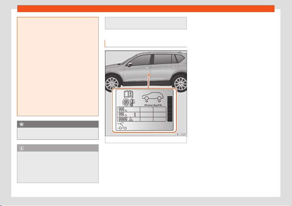
Wheels
●
Always ensure that the tyres you have
chosen hav
e adequate clearance. When
selecting replacement tyres, do not rely
entirely on the nominal tyre size marked on
the tyre, since the nominal tyre size can dif-
fer significantly depending on the manu-
facturer. Lack of clearance can damage
the tyres or the vehicle and, as a result, en-
danger road safety. Risk of accident!
●
Only use tyres that are over 6 years old in
an emergency, and drive with due care.
●
The fitting of tyres with run-flat proper-
ties is not permitted on your vehicle! Pro-
hibited use can cause accidents or can
damage your vehicle.
●
If decorative hubcaps are subsequently
fitted, make sure that they allow enough air
in to cool the braking system. Risk of acci-
dent!
For the sake of the environment
Old tyres must be disposed of according to
the laws in the country concerned.
Note
●
A SEAT Service Centre should be consul-
ted to find out whether wheels or t
yres of
different sizes to those originally fitted by
SEAT can be fitted, and to find out about
the combinations allowed between the
front axle (axle 1) and the rear axle (axle 2).
●
Never mount used tyres if you are not
sure of their “pr
evious history”.
Tyre life
Fig. 319 Location of the tyre pressure sticker.
Correct inflation pressures and sensible driv-
ing habits will incr
ease the useful lif
e of your
t
yr
es.
●
Check t
yr
e pr
essure at least once a month,
and also prior to any long trip.
●
The tyre pressure should only be checked
when the tyres are cold. Do not reduce the
pressure of warm tyres.
●
Adjust tyre pressure to the load being car-
ried by the vehicle
›››
Fig. 319.
●
In vehicles with a tyre pressure indicator,
save the modified tyre pressure
›››
page 369.
●
Avoid fast cornering and hard acceleration.
●
Inspect the tyres for irregular wear from
time to time.
Tyre pressure
The tyre inflation pressures are listed on a
sticker on the rear of the front left door frame
›››
Fig. 319.
Insufficient or excessive pressure greatly re-
duces the useful life of the tyres and adverse-
ly affects vehicle performance and ride. Cor-
rect inflation pressures are very important,
especially at high speeds.
Depending on the vehicle, tyre pressure can
be adjusted to medium load to improve driv-
ing comfort (tyre pressure
›››
Fig. 319).
When driving with comfort tyre pressure fuel
consumption may increase slightly.
The tyre pressure must be adjusted accord-
ing to the load the vehicle is carrying. If the
vehicle is going to carry the maximum load,
the tyre pressure should be increased to the
maximum value indicated on the sticker
›››
Fig. 319.
»
365
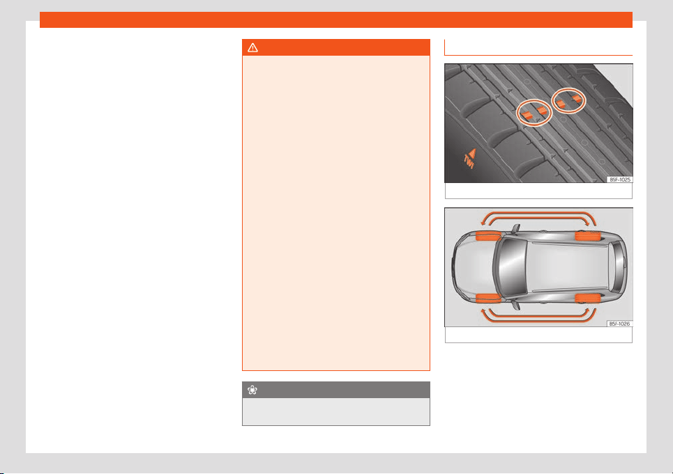
Practical tips
Do not forget the spare wheel when checking
the t
yr
e pr
essur
es: K
eep this spar
e wheel in-
fl
ated to the highest pressure required for the
road wheels.
In the case of a minimised temporary spare
wheel (125/70 R18) inflate to a pressure of 4.2
bar as indicated on the tyre pressure label
›››
Fig. 319.
Driving style
Fast cornering, heavy acceleration and hard
braking (squealing tyres) all increase tyre
wear.
Wheel balance
The wheels on new vehicles are balanced.
However, certain circumstances may lead to
imbalance (run-out), which is detected as vi-
brations in the steering wheel.
Unbalanced wheels should be rebalanced,
as they otherwise cause excessive wear on
steering, suspension and tyres. A wheel must
also be rebalanced when a new tyre is fitted
or if a tyre is repaired.
Incorrect wheel alignment
Incorrect running gear alignment causes ex-
cessive tyre wear, impairing the safety of the
vehicle. If you notice excessive tyre wear, you
should check wheel alignment at a SEAT Of-
ficial Service.
WARNING
Unsuitable handling of the wheels and
tyres may lead to sudden tyre pr
essure los-
ses, to tread separation or even to a blow-
out.
●
The driver is responsible for ensuring that
all of the vehicle tyres are correctly infla-
ted to the right pressure. The recommen-
ded tyre pressure is indicated on the label
›››
Fig. 319.
●
Check tyre pressures regularly and en-
sure they are maintained at the pressures
indicated. Tyre pressure that is too low
could cause overheating, resulting in tread
detachment or even burst tyres.
●
When the tyres are cold, tyre pressure
should be that indicated on the label
›››
Fig. 319.
●
Regularly check the cold inflation pres-
sure of the tyres. If necessary, change the
tyre pressure of the vehicle tyres while they
are cold.
●
Regularly check your tyres for damage
and wear.
●
Never exceed the maximum permitted
speed or loads specified for the type of
tyre fitted on your vehicle.
For the sake of the environment
Under-inflated tyres will increase fuel con-
sumption.
Tread wear indicators
Fig. 320
Tyre profile: tread wear indicators.
Fig. 321
Interchanging tyres.
Wear indicators around 1.6 mm high can be
f
ound on the base of the original t
yr
e tr
eads,
or
der
ed at r
egular intervals and running
across the tread
›››
Fig. 320. The letters "TWI"
or triangles on the sidewall of the tyre mark
the position of the wear indicators.
366
Wheels
The minimum permitted profile depth
1)
hav
e
been r
eached when the t
yr
es hav
e w
orn
do
wn to the wear indicators. Replace the
tyres with new ones
›››
.
Changing wheel
s ar
ound
T
o ensur
e that the w
ear is equal on all t
yr
es
the wheels should be changed round from
time to time according to the system
›››
Fig. 321. The useful life of all the tyres will
then be about the same time.
WARNING
The tyres must be replaced at the latest
when the tread is worn down to the tread
wear indicat
ors. Failure to follow this in-
struction could result in an accident.
●
Particularly in difficult driving conditions
such as wet or icy roads. It is important that
the tyre tread be as deep as possible and
be approximately the same on the tyres of
both the front and the rear axles.
●
The scant driving safety due to insuffi-
cient tread depth is particularly evident in
vehicle handling, when there is a risk of
“aquaplaning” in deep puddles of water
and when driving through corners, and
braking is also adversely affected.
●
The speed has to be adapted according-
ly, otherwise there is a risk of losing control
o
ver the vehicle.
Wheel nuts
The wheel nuts are matched to the rims.
When installing different wheel
s (for instance
alloy wheels or wheels with winter tyres) it is
important to use the correct wheel nuts with
the right length and correctly shaped bolt
heads. This ensures that wheels are fitted se-
curely and that the brake system functions
correctly.
The wheel nuts must be clean and turn easily.
A special adapter is required to turn the anti-
theft wheel nuts*
›››
page 45.
WARNING
Wheel nuts should never be greased or
oiled.
●
Use only wheel nuts which belong to the
wheel.
●
If the prescribed torque of the wheel nuts
is t
oo low, they could loosen whilst the ve-
hicle is in motion. Risk of accident! If the
tightening torque is too high, the wheel nuts
and threads can be damaged.
CAUTION
See
›
››
page 48 to find out the r
ecommen-
ded tightening torque for wheel nuts for
steel and alloy rims.
Winter tyres
–
Winter tyres must be fitted on all f
our
wheel
s.
–
Only use wint
er t
yr
es that ar
e appr
oved for
your vehicle.
–
Please note that the maximum permissible
speed for winter tyres may be lower than
for summer tyres.
–
Also note that winter tyres are no longer ef-
fective when the tread is worn down.
–
After fitting the wheels you must always
check the tyre pressures. When doing so,
take into account the correct tyre pressures
listed on the rear of the front left door frame
›››
page 365.
In winter road conditions winter tyres will con-
siderably improve vehicle handling. The
»
1)
Follow the regulations of the country you are
driving in.
367
Practical tips
design of summer tyres (width, rubber com-
pound, tr
ead patt
ern) giv
es l
ess grip on ice
and sno
w
. This applies particul
arly to vehicles
equipped with wide section tyres or with
high speed tyres (code letters H, V or Y on
the sidewall).
Only use winter tyres of the correct type ap-
proved for your vehicle. The sizes of these
tyres are specified in the vehicle's documents
(e.g. EC Certificate of Conformity or COC
1)
).
The vehicle documentation varies depending
on the country of residence.
Winter tyres lose a great deal of their proper-
ties when the tread is worn down to a depth
of 4 mm.
The performance of winter tyres is also se-
verely impaired by ageing, even if the tread is
still much deeper than 4 mm.
A code letter indicating the speed limit is
stamped on all winter tyres
›››
page 363.
Vehicles capable of exceeding these speeds
must have an appropriate sticker attached
so that it is visible to the driver. Suitable stick-
ers are available from the SEAT Official Serv-
ice and specialised workshop. Please note
the regulations to this effect in your country.
“All-weather” tyres can also be used instead
of winter tyres.
Using winter tyres with V-rating
Please note that the generally applicable
240 km/h (149 mph) speed for winter tyres
with the letter V is subject to technical re-
strictions; the maximum permissible speed
for your vehicle may be significantly lower.
The maximum speed limit for these tyres de-
pends directly on the maximum axle weights
for your car and on the listed weight rating of
the tyres being used.
It is best to contact a SEAT Official Service to
check the maximum speed which is permissi-
ble for the V-rated tyres fitted on your car on
the basis of this information.
WARNING
Exceeding the maximum speed permitted
for the winter tyres fitted on your car can
cause tyr
e failure, resulting in a loss of con-
trol of the vehicle – risk of accident.
For the sake of the environment
When winter is over, change back to sum-
mer tyres at an appropriate moment. In
temperat
ures above +7°C (+45°F), perform-
ance will be improved if summer tyres are
used. Fuel consumption, wear and noises
while driving will all be reduced.
Snow chains
Snow chains must only be fitted to the front
wheels, even on v
ehicles with four-wheel
drive.
●
Check that they are correctly seated after
driving for a few yards; correct the position if
necessary, in accordance with the manufac-
turer's fitting instructions.
●
Keep your speed below 50 km/h (30 mph).
●
If there is a danger of being trapped de-
spite having mounted the chains, it is best to
disable the driving wheels (ASR) in the ESC
›››
page 304, Connecting and disconnect-
ing the ESC and ASR.
Snow chains will improve braking ability as
well as traction in winter conditions.
For technical reasons snow chains may only
be used with the following wheel rim/tyre
combination.
215/65 R17 Chains with links of maximum 9 mm
Other dimensions do not allow chains
Remove any central wheel trims and the rim
ring bef
or
e fitting sno
w chains.
1)
COC = certificate of conformity.
368
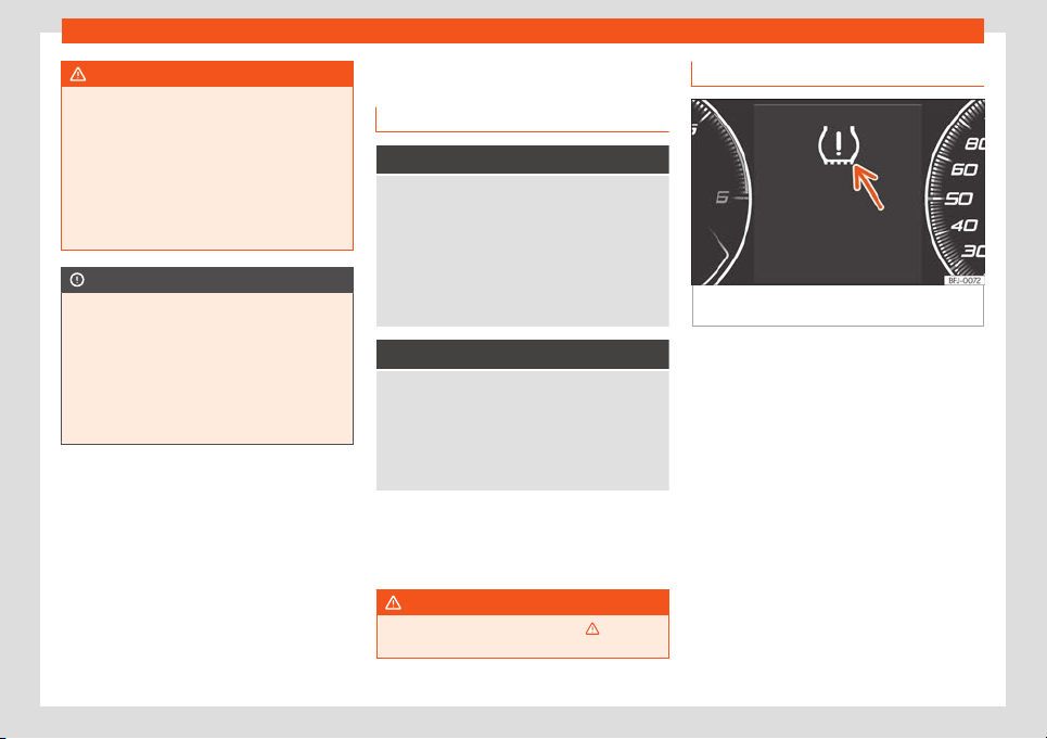
Wheels
WARNING
The use of unsuitable or incorrectly fitted
chains could lead to serious accidents and
damage.
●
Always the appr
opriate snow chains.
●
Observe the fitting instructions provided
by the snow chain manufacturer.
●
Never exceed the maximum permitted
speeds when driving with snow chains.
CAUTION
●
Remove the snow chains to drive on
r
oads without snow. Otherwise they will im-
pair vehicle handling, damage the tyres
and wear out very quickly.
●
Wheel rims may be damaged or scratch-
ed if the chains come into direct contact
with them. SEAT recommends the use of
covered snow chains.
Tyre pressure loss indicator
Contr
ol l
amp
It lights up
The inflation pressure of one or more wheels is much
lower than the value set by the driver, or the tyre has
structural damage.
In addition, a audible warning sounds and a text
message is displayed on the instrument panel
screen.
Stop the vehicle! Stop the vehicle safely as soon
as possible. Check all tyres and pressures. Replace
any damaged tyres.
Flashes
System fault
The control lamp flashes for approximately 1 minute
and then lights up permanently.
If the tyre is inflated correctly, switch the ignition off
and on again. Re-calibrate the tyre pressure loss in-
dicator
›››
page 370. If the fault continues, go to a
specialised workshop.
Several control and warning lamps light up
f
or a f
e
w seconds when the ignition is s
wit
ch-
ed on whil
e the function is v
erified. They will
switch off after a few seconds.
WARNING
Observe the safety warnings
›››
in Con-
trol and warning lamps on page 81.
Tyre monitor system
Fig. 322
Instrument panel: warning of loss of
t
yr
e pr
essur
e
.
The tyre monitor indicator compares wheel
r
e
v
olutions and, with this inf
ormation, the
tr
ead of each wheel using the ABS sensors.
If the r
olling cir
cumference of one or more
wheels has changed, the tyre monitoring indi-
cator will indicate this on the instrument pan-
el through a warning lamp and a warning to
the driver
›››
Fig. 322. When only one specific
tyre is affected, its position within the vehicle
will be indicated.
Loss of pressure: Check left
tyre pressure!
Wheel tread change
The wheel diameter changes when:
●
Tyre pressure is changed manually.
●
Tyre pressure is insufficient.
»
369
Practical tips
●
The t
yr
e struct
ur
e is damaged.
●
The v
ehicl
e is unbal
anced because of a
load.
●
The wheels on an axle are subject to a
heavier load (e.g. with a heavy load).
●
The vehicle is fitted with snow chains.
●
The temporary spare wheel is fitted.
●
The wheel on one axle is changed.
There may be a delay in the reaction of the
tyre monitoring indicator or it may not indi-
cate anything under certain circumstances
(e.g. sporty driving, snow-covered or un-
paved roads, or when driving with snow
chains).
Calibrating the tyre monitoring indicator
After changing the tyre pressure or replacing
one or more wheels, the tyre monitoring indi-
cator must be recalibrated. Do the same, for
example, when the front and rear wheels are
swapped.
●
Switch the ignition on.
●
Store the new inflation pressure in the Easy
Connect system with the button > SET-
TINGS > Tyres
›››
page 82 .
When driving, the system self-calibrates the
tyre pressure provided by the driver and the
wheels fitted. After a long journey with varied
speeds the programmed values are collected
and monitored.
With the wheels under very heavy loads, the
tyre pressure must be increased to the total
recommended tyre pressure before calibra-
tion
›››
Fig. 319.
WARNING
When the tyres are inflated at different
pressures or at a pressure that is too lo
w
then a tyre may be damaged resulting in a
loss of control of the vehicle and a serious
or fatal accident.
●
If the lamp lights up, reduce speed im-
mediately and avoid any sudden turning or
braking manoeuvre. Stop when possible,
and check the tyre pressure and status.
●
The tyre monitoring system can only op-
erate correctly if all of the tyres are infla-
ted to the correct pressure when cold.
●
If a tyre has not been punctured and it
does not have to be changed immediately,
drive to the nearest specialised workshop
at a moderate speed and have the tyre
checked and inflated to the correct pres-
sure.
Note
●
Driving for the first time with new tyres at
a high speed can cause them to slightly ex-
pand, which coul
d then produce an air
pressure warning.
●
If excessively low tyre pressure is detec-
ted with the ignition on, an audible warning
will sound. In the event that there is a fault
in the system, an audible warning will
sound.
●
Driving on dirt tracks for a long period of
time or driving in a sporty style can tempo-
rarily deactiv
ate the TPMS. The control
lamp shows a fault, but disappears when
road conditions or the driving style change.
●
Do not only rely on the tyre monitoring
system. Regularly check your tyres to en-
sure that the tyre pressure is correct and
that the tyres are not damaged due to
puncture, cuts, tears and impacts/dents.
Remove objects from the tyres only when
they have not pierced the tyres.
●
The tyre monitoring indicator does not
function when there is a fault in the ESC or
ABS
›››
page 302.
370
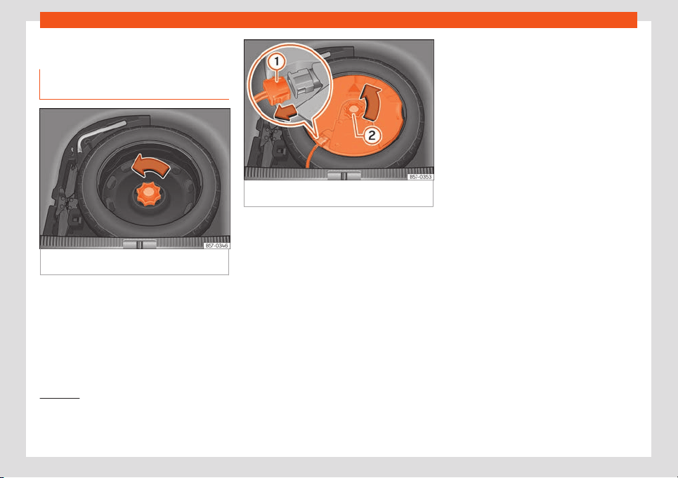
Wheels
Spare wheel
L
ocation and use of the t
empor
ary
spar
e wheel
Fig. 323
In the luggage compartment: load
fl
oor r
aised.
Fig. 324
In the luggage compartment: remove
the sub
w
oof
er
.
The temporary spare wheel is stored under
the fl
oor panel in the luggage compartment
and is att
ached by a thumbnut.
The t
empor
ary spar
e wheel has been de-
signed t
o be used f
or short periods of time.
Have the tyres checked and replaced as
soon as possible at a SEAT Official Service or
at a specialised workshop.
The spare wheel must not be switched for a
spare wheel from another vehicle.
Removing the temporary spare wheel (5-
seat vehicles)
●
Lift and hold up the floor panel to remove
the temporary spare wheel
›››
page 138.
●
Turn the thumb wheel anti-clockwise
›››
Fig. 323.
●
Take out the temporary spare wheel.
Removing the temporary spare wheel (7-
seat vehicles)
●
Remove the luggage compartment floor.
●
Pull up on the bottom, side cords of the 3rd
row of seats until latching in the upper posi-
tion.
●
Remove the transversal side wall.
●
Turn the thumb wheel anticlockwise
›››
Fig. 323
1)
.
●
Take out the temporary spare wheel.
●
To put the temporary spare wheel back in
place, proceed in the reverse order.
»
1)
If the vehicle is outfitted with the Beats Audio
system with a subwoofer*, before r
emoving the
spare wheel, proceed as instructed in
›››
page 372.
371
Practical tips
Getting the spare wheel out of vehicles
with BEAT
S Audio 10 speak
ers (with
sub-
w
oof
er
)*
T
o remove the spare wheel, you must first re-
move the subwoofer.
●
Lift and secure the luggage compartment
floor as explained in
›››
page 138.
●
Disconnect the subwoofer
›››
Fig. 324
1
speaker cable.
●
Turn the securing wheel in an anti-clock-
wise dir
ection
›
›
›
Fig. 32
4
2
.
●
Remove the sub
w
oof
er
speak
er and the
spar
e wheel.
●
When r
e-mounting the spare tyre, place the
subwoofer on the base of the wheel rim with
care. When doing so, the tip of the “FRONT”
arrow on the subwoofer should point forward.
●
Reconnect the speaker cable and firmly ro-
tate the securing wheel clockwise so that the
subwoofer system and wheel are firmly in
place.
Chains
For technical reasons, snow chains must not
be used on the temporary spare wheel.
If you have a puncture on one of the front
wheels when using snow chains, fit the tem-
porary spare wheel in place of one of the rear
wheels. Fit the snow chains on the rear wheel
that you have removed and replace the
punctured front wheel with this wheel.
WARNING
Keep in mind that the standard wheel is
wider than the emergency spare wheel, so
the 3rd row of seats cannot be complet
ely
lowered when that standard wheel is
placed in the emergency spare wheel well.
●
Do not drive if the 3rd row of seats is not
correctly fastened by the anchors. Risk of
serious injury.
WARNING
●
After fitting the temporary spare wheel,
check the tyre pr
essures as soon as possi-
ble. Failure to do so may cause an acci-
dent. The tyre pressure is listed on the back
of the left front door frame
›››
Fig. 319.
●
Do not drive at over 80 km/h (50 mph)
when the temporary spare wheel is fitted
on the vehicle: risk of accident!
●
Never travel more than 200 km using a
temporary spare wheel.
●
Avoid heavy acceleration, hard braking
and fast cornering: risk of accident!
●
Never use more than one temporary
spare wheel at the same time, risk of acci-
dent.
●
No other type of tyre (normal summer or
winter tyre) may be fitted on the compact
temporary spare wheel rim.
●
If you are driving using the spare wheel,
the ACC system could automatically
switch off during the journey. Switch off the
system when starting off.
372
SEAT Maintenance Programme
Maintenance
SEAT Maint
enance Pr
o-
gr
amme
Service int
erv
al
s
Service w
ork and the Digital Main-
tenance Plan
Log of services performed (“Digital Main-
t
enance Pl
an”)
The SEAT deal
ership or a specialised w
ork
-
shop r
ecor
ds Service receipts in a central
system. Thanks to this comprehensive docu-
mentation of the service history, it is possible
to reproduce the services performed any
time. SEAT recommends requesting a Service
receipt after every service carried out con-
taining all the services carried out on the sys-
tem.
Whenever there is a new service the receipt is
replaced with a current one.
The Digital Maintenance Plan is not avail-
able in some markets. In this case, your
SEAT dealer will inform you about the cur-
rent documentation of the work.
Service works
In the Digital Maintenance Plan, your SEAT
authorised service or specialised workshop
documents the following information:
●
When each one of the services was carried
out.
●
Whether a specific repair has been sugges-
ted, e.g. changing the brake pads in the near
future.
●
If you have expressed a special request for
the maintenance. Your Service Advisor will
write the work order.
●
The components or fluids that were
changed.
●
The date of the next service.
The Long Life Mobility Warranty is valid until
the next inspection. This information is docu-
mented in all checks performed.
The type and the volume of the service may
vary from one vehicle to another. A special-
ised workshop will be able to provide specific
information on the jobs for your vehicle.
WARNING
If the services are insufficient or not per-
formed and if the service intervals are not
observed, the v
ehicle may be immobilised
in traffic cause an accident and severe in-
juries.
●
Make sure that any repairs are carried
out by a SEAT authorised service or speci-
alised workshop.
CAUTION
SEAT cannot be held liable for any damage
t
o the vehicle due to insufficient work or of
lack of av
ailability of spare parts.
Note
Regular services on the vehicle not only
maintain its value, but also its correct oper-
ation and r
oad safety. For this reason, con-
duct the services in accordance with SEAT
guidelines.
Set Service or Flexible Service In-
t
erv
al
s
Services are classified as oil change service
and inspection. The service int
erv
al displ
ay
on the instrument panel displ
ay serv
es as a
r
eminder of the ne
xt service.
Depending on the features, the engine and
the conditions of use of the car, either the
Fixed service or the Flexible service will be
applied for an oil change service..
»
373

Maintenance
How to know which type of service needs
t
o his v
ehicl
e
●
Check the t
abl
es bel
o
w:
Oil change service
a)
PR No.
Type of
service
Service interval
QI1
Fixed
Every 5000 km or after
1 year
b)
QI2
Every 7500 km or after
1 year
b)
QI3
Every 10000 km or after
1 year
b)
QI4
Every
15000 km or after
1 year
b)
QI6 Fle
xible
According to the service in-
t
erv
al displ
ay
a)
The data are based on normal conditions of use.
b)
Whatever happens first.
Inspection Service
a)
According to the service interval display
a)
The data are based on normal conditions of use.
Bear in mind the inf
ormation about the speci-
fications of the engine oil accor
ding t
o the
VW st
andar
d
›
›
›
page 353.
Particular characteristics of the Flexible
Service
Regarding the Flexible Service, the oil
change service only has to be performed
when the vehicle needs it. To calculate when
you have to carry out this service, take into
account the individual conditions of use and
personal driving style. A major component of
the flexible service the use of LongLife oil in-
stead of conventional engine oil.
Bear in mind the information about the speci-
fications of the engine oil according to the
VW standard
›››
page 353.
If you do not want to the flexible service
you can select the fixed service However,
a fixed service may affect service costs
The Service Advisor will gladly advise you.
Service interval display
At SEAT, the dates of the services are indica-
ted by the service interval display on the in-
strument panel
›››
page 77 or in the Vehicle
settings menu of the infotainment system
›››
page 82.
The service interval display gives information
for service dates that involve an engine oil
change or an inspection. When the time for
the corresponding service comes, additional
work required, such as the change of brake
fluid and the spark plugs, can be carried out.
Information about the terms of use
The service intervals and groups are usually
based on normal conditions of use.
If, on the other hand, the vehicle is under ad-
verse conditions of use, some of the w
ork
must be carried out before the next service
period or even between service intervals.
Conditions of use adverse include:
●
The use of fuel with a high sulphur content.
●
Frequent short trips.
●
Letting the engine idle for a long period of
time, as in the case of taxis.
●
Using the vehicle in areas with thick dust.
●
Frequent driving with a tr
ailer (depending
on equipment).
●
Using the vehicle mostly in situations with a
lot of traffic and stops (e.g. in a city).
●
Using the vehicle mostly in winter.
This applies especially for the following
parts (depending on equipment):
●
Dust and pollen filter
●
Air Care allergen filter
●
Air filter
●
Toothed chain
●
Particulate filter
●
Engine oil
374
SEAT Maintenance Programme
The Service Advisor of your specialised
w
orkshop will gl
adly inf
orm you
about the
need of perf
orming service w
ork betw
een
normal service intervals, always considering
the conditions of use of your vehicle.
WARNING
If the services are insufficient or not per-
formed and if the service intervals are not
observed, the v
ehicle may be immobilised
in traffic and cause accidents and severe
injuries.
●
Have the services conducted at author-
ised SEAT services or specialised work-
shops.
CAUTION
SEAT cannot be held liable for any damage
to the vehicle due to insufficient work or of
lack of av
ailability of spare parts.
Service sets
Sets of services include all the maint
enance
w
orks
needed t
o ensur
e the saf
et
y and the
smooth running of the vehicle (depending on
the conditions of use and the features of
the vehicle, such as the engine, gearbox, or
operating fluids). Maintenance services are
divided into inspection and review services.
Consult the details of the jobs required for
your vehicle at:
●
Your SEAT authorised service
●
Your specialised workshop
Due to technical reasons (continuous devel-
opment of components) the sets of services
may vary. Your SEAT authorised service or
specialised workshop is always receiving up-
dates in time.
Additional service offers
Approved spare parts
Original SEAT Spare Parts have been con-
ceiv
ed f
or their v
ehicl
es and appr
o
v
ed by
SEAT, with a special emphasis on safety.
These parts correspond exactly to the manu-
facturer's requirements in terms of design,
accuracy of the measurements and materi-
als. The original SEAT Spare Parts have been
conceived exclusively for your vehicle. For this
reason, we always recommend the use of
Original SEAT Spare Parts. SEAT cannot be
held liable for the safety and suitability of
parts from other manufacturers.
Approved spare parts
Approved spare parts, following the manu-
f
act
ur
er
's r
equir
ements, ar
e an additional
service to you, offering the possibility of re-
placing complete sets, such as: light engine,
gearboxes, heads, control units, electrical
components, etc.
These parts are, approved parts, and are the
same as the factory parts, which are also ap-
proved spare parts.
Original accessories
We recommend you only use SEAT Original
Accessories and SEAT approved accessories
for your vehicle
. The reliability, safety and
suitability of these accessories have been in-
spected specifically for this type of vehicle.
SEAT cannot be held liable for the safety and
suitability of parts from other manufacturers.
SEAT Service Mobility
Since the moment you purchase your SEAT
v
ehicl
e you will be abl
e t
o enjoy the benefits
and co
v
er
age of the SEAT Mobility Service.
For the first two years after the purchase,
your new SEAT vehicle is automatically cov-
ered by the SEAT Mobility Service without ad-
ditional costs.
If you wish to enjoy this service after this peri-
od, you can extend SEAT Mobility as long as
you carry out the recommended Inspection
»
375
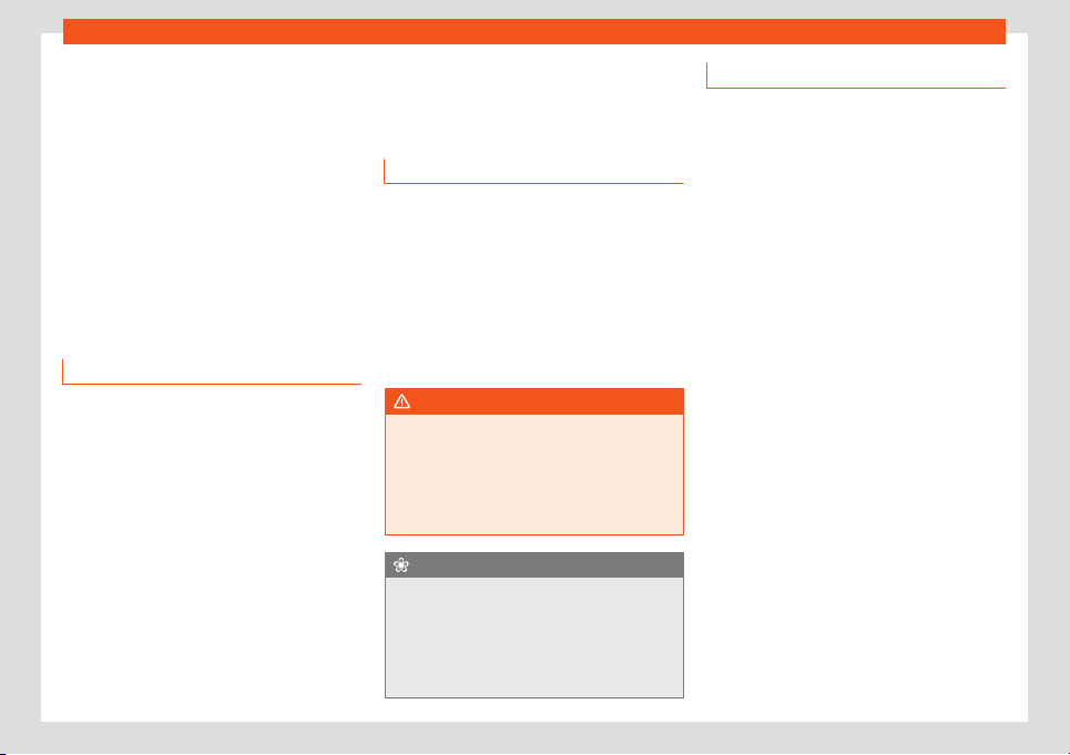
Maintenance
and Maintenance Services at a SEAT Author-
ised Service
.
If your SEAT v
ehicl
e is immobilised due t
o a
f
ault or an accident, our assist
ance services
will help you k
eep moving.
Take into account that the SEAT Mobility
Service differs depending on the country in
which the vehicle was purchased. For further
information ask your SEAT dealership or the
SEAT website in your country.
Warranty
Fault-free operation warranty
SEAT Authorised Services ensure the perfect
condition of ne
w v
ehicl
es. Check the pur
-
chase agr
eement or compl
ement
ary addi-
tional documentation provided by your Tech-
nical Service to see the conditions and the
terms of the warranty. Consult further infor-
mation in this regard in your SEAT Official
Service.
Vehicle maintenance
Maint
enance and cl
eaning
Basic observ
ations
Regular and careful care helps to maintain
the value of your vehicle. In addition, it may
become a prerequisit
e to demand the war-
ranty in the event of corrosion damage and
deficiencies in the paint coat of the body-
work.
Specialised workshops have the necessary
care products. Please follow the instructions
for application on the packaging.
WARNING
●
Cleaning products and other materials
used for car care can be damaging t
o your
health if misused.
●
Always keep care products in a safe
place, out of the reach of children. Danger
of poisoning!
For the sake of the environment
●
When purchasing car care products,
chose products that are compatible with
the envir
onment.
●
The waste from car-care products should
not be disposed of with ordinary household
waste.
Washing the vehicle
The longer you take to clean the tanks, e.g.
remains of insects, bird excrements, tree r
esin
or anti frost salt adhered to your vehicle, the
more damage it can cause to the surface.
High temperatures, for instance strong sun-
light, further intensify the damage.
Before washing the car, soften the dirt using
plenty of water.
To remove encrusted dirt such as insects, bird
droppings or tree resin, use a lot of water and
a microfibre cloth.
Have the underside of the vehicle washed af-
ter the end of the anti frost salts in winter.
High pressure cleaning equipment
When washing the vehicle with a high-pres-
sure cleaner, always follow the operating in-
structions for the equipment. This applies
particularly to the operating pressure and the
distance between the spraying water. Do not
aim the jet directly to the side window gas-
kets, doors, covers or the panoramic sun-
roof*; the same applies to tyres, rubber ho-
ses, soundproofing material, sensors* or
camera lenses*. Keep a distance of at least
40 cm.
Do not remove snow and ice with a high-
pressure cleaner.
376
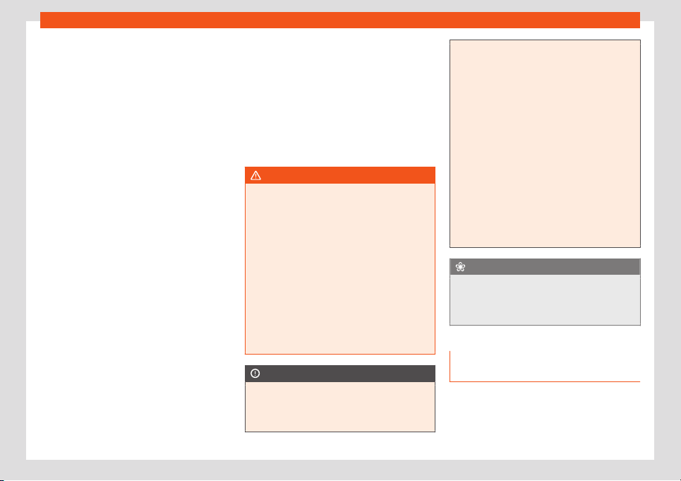
Vehicle maintenance
Do not use a nozzle that sprays the water out
in a dir
ect str
eam or one that has a r
ot
ating
jet f
or f
or
cing off dirt.
The water temperature must not exceed
60°C.
Automatic car washes
Spray the vehicle before starting the car
wash.
Make sure that the windows and the panor-
amic sunroof* are closed and the windscreen
wipers are deactivated. Bear in mind the in-
structions of the car wash tunnel operator,
especially if your vehicle has detachable
parts.
Use of car washes without brushes if possible.
Washing by hand
Clean your vehicle from top to bottom with a
soft sponge or with a brush. Only use clean-
ing products that do not contain solvents.
Washing vehicles with a matte paint by
hand
To prevent damage to the vehicle when
washing it, first remove the thicker dust and
dirt. To remove traces of insects, grease and
fingerprints, it is best to use a special cleaner
for matte paint.
Apply the product with a microfibre cloth. To
avoid damaging the surface of the paint, do
not apply too much pressure.
Rinse with plenty of water. Then clean it with
a neutral cleaning product and a soft microfi-
bre cloth.
Rinse the vehicle again with plenty of water
and then leave it to dry. Remove traces of
water with a leather cloth.
WARNING
●
Only wash the vehicle with the ignition
switched off or according t
o the specifica-
tions of the car wash tunnel operator. Risk
of accident!
●
When cleaning the underbody or the in-
side of the wheel arches, protect yourself
from sharp or pointy metal parts. Risk of
cut!
●
After cleaning the brakes could act more
slowly due to moisture or, in winter, the ice
on the brake discs and pads. Risk of acci-
dent! In this case the brakes should be
dried by pressing the brake pedal several
times.
CAUTION
●
Before washing the vehicle in an auto-
matic car w
ash, please make sure to re-
tract the exterior mirrors to prevent them
from being damaged. Electric exterior rear-
view mirrors must always be folded/de-
ployed electrically!
●
Do not wash the vehicle in direct sunlight.
Risk of damaging the paint job!
●
Do not use sponges, abr
asive household
sponges or similar to clean insect remains.
Risk of damaging the surface!
●
Vehicle parts with matte paint:
–
Do not use polish or hard wax. Risk of
damaging the surface!
–
Never select washing programs that in-
clude the use of wax. This could dam-
age the appearance of matte paint.
–
Do not put stickers or magnets on parts
with matte paint, as removing them
may damage the paint.
For the sake of the environment
The car should only be washed in special
wash bays. These places are prepared to
pr
event oily water from getting into the
public drains.
Cleaning and maintenance instruc-
tions
The cleaning and maintenance of individual
components of the v
ehicl
e can be check
ed in
the f
oll
o
wing t
ables. The contents should be
understood merely as a recommendation. Go
to your specialised workshop if you have
»
377
Maintenance
special questions or parts that are not listed.
T
ak
e he gener
al consider
ations int
o account
›
›
›
in Take special care with... on
page 381.
Cleaning the exterior
Windscreen wipers
Problem Solution
Dirt Soft cloth with wipers
Headlights / Tail lights
Problem Solution
Dirt Soft sponge with neutral soap
solution
a)
a)
Neutral soap solution: two tablespoons maximum in
1 litr
e of w
at
er
Sensors / Camer
a l
enses
Problem Solution
Dirt
Sensors: soft cloth with a sol-
vent-free cleaning pr
oduct
Camera lenses: soft cloth with
an alcohol-free cleaning prod-
uct
Snow/ice
Hand brush/Anti frost spray
with no solvents
Wheels
Problem Solution
Antifreeze salt Water
Brake abrasion
dust
Acid-free special cleaning
product
End exhausts
Problem Solution
Antifreeze salt Water, if a steel cleaning prod-
uct is required
Covers / Trims
Problem Solution
Dirt Neutral soap solution
a)
, if a
steel cleaning product is re-
quired
a)
Neutral soap solution: two tablespoons maximum in
1 litr
e of w
at
er
P
aint
Problem Solution
Paint flaws
Check the paint's colour code
in an authorised service and re-
store with a touch-up pencil
Spilled fuel Immediat
ely rinse with water
Environmental rust
tank
Apply rust remover and then
apply hard wax. Go you your
specialised w
orkshop if you
have any queries
Problem Solution
Corrosion
Have your specialised work-
shop take care of this
The water does
not creat
e drop-
lets on the clean
paint
Maintain with har
d wax (at
least 2 times a year)
No shine de-
spite sober main-
tenance/paint
Treat with suitable w
ax and ap-
ply paint preservative after-
war
ds if the wax used does not
contain preservative ingredi-
ents
Tanks, e.g. insect
remains, bird
droppings, tree
sap, road salt
Immediat
ely soften with water
and remove with a microfibre
cloth
Fat-based dirt,
e.g. cosmetic
products or
sunscreen
Delete immediately with a neu-
tral soap solution
a)
and a soft
cloth
a)
Neutral soap solution: two tablespoons maximum in
1 litr
e of w
at
er
Carbon fibr
e par
ts
Problem Solution
Dirt Clean the same way as pain-
ted parts
›››
page 376
378
Vehicle maintenance
Decoration slides
Problem Solution
Dirt Soft sponge with neutral soap
solution
a)
a)
Neutral soap solution: two tablespoons maximum in
1 litre of water
Interior cleaning
Windows
Problem Solution
Dirt Apply windscreen cleaner and
then dry with a cloth
Covers / Trims
Problem Solution
Dirt Neutral soap solution
a)
a)
Neutral soap solution: two tablespoons maximum in
1 litr
e of w
at
er
Pl
astic par
ts
Problem Solution
Dirt Damp cloth
Encrusted dirt Neutral soap solution
a)
, if pos-
sible solvent-free plastic clean-
er
a)
Neutral soap solution: two tablespoons maximum in
1 litr
e of w
at
er
Displ
ays/instrument panel
Problem Solution
Dirt Soft cloth with a liquid crystal
display cleaner
Control panels
Problem Solution
Dirt Soft brush, then soft cloth with
neutral soap solution
a)
a)
Neutral soap solution: two tablespoons maximum in
1 litre of water
Seat belts
Problem Solution
Dirt Neutral soap solution
a)
, al-
lowed to dry befor
e retracting
a)
Neutral soap solution: two tablespoons maximum in
1 litr
e of w
at
er
F
abrics, ar
tificial
, Al
cantara leather
Problem Solution
Particles of dirt
stuck to surfaces
Vacuum cleaner
Wat
er-based dirt,
e.g. coffee, tea,
blood etc.
Absorbent cl
oth and neutral
soap solution
a)
Problem Solution
Grease-based
dirt, e.g. oil, make-
up, etc.
Apply a neutral soap solution
a)
.
Absorb the dissol
ved grease
and paint particles drying with
an absorbent cloth, in case you
must treat it with water after-
wards
Special dirt, e.g.
pens, nail polish,
dispersion paint,
shoe cream etc.
Special stain remove: dry with
an absorbent cl
oth, if applica-
ble, apply neutral soap solution
afterwards
a)
a)
Neutral soap solution: two tablespoons maximum in
1 litr
e of w
at
er
Nat
ur
al l
eather
Problem Solution
Recent dirt Cotton cloth with neutral soap
solution
a)
Water-based dirt,
e.g. coffee, tea,
blood etc.
Recent stains: absorbent cloth
Dry stains: stain remover suita-
ble for leather
Grease-based
dirt, e.g. oil, make-
up, etc.
Recent st
ains: absorbent cloth
and suitable stain remover for
leather
Dry stains: grease solvent
spray
Special dirt, e.g.
pens, nail polish,
dispersion paint,
shoe cream etc.
Stain remover suit
able for
leather
»
379

Maintenance
Problem Solution
Care Apply preservative cream regu-
larly to protect from sunlight.
Use a colour pr
eservative if re-
quired
a)
Neutral soap solution: two tablespoons maximum in
1 litre of water
Carbon fibre parts
Problem Solution
Dirt Clean like plastic parts
Take special care with...
Headlights/tail lights
●
Do not clean the headlights/tail lights with
a dry cl
oth or sponge
.
●
Do not use cl
eaning pr
oducts that cont
ain
al
cohol. Risk of cr
acks!
Wheels
●
Do not use for paint wax or other abrasive
products.
●
If the protective coating on the paint of the
rim has been damaged due to stone impacts,
scratches, etc., the damage should be re-
paired immediately.
Camera lenses
●
Do not use hot or warm water to remove ice
or snow from the camera lenses. Risk of
cracking the lens!
●
To clean the camera lens, never use abra-
sive cleaning products or products with alco-
hol. Risk of scratches and cracks!
Windows
●
Remove snow and ice from windows and
exterior mirrors with a plastic scraper only. To
avoid scratches, the scraper should only be
pushed in one direction and not moved to
and fro.
●
Never remove snow or ice from windows
and rearview mirrors with warm or hot water.
Risk of cracks on the windows!
●
To prevent damage to the heating of the
rear window, do not put stickers over the
heating elements.
Covers/trims
●
Do not use cleaning products or chrome
based cleaning agents.
Paint
●
The vehicle must be free from dirt and dust
before applying wax or care products. Risk of
scratches!
●
Do not apply wax or care products if the
vehicle is exposed to direct sunlight. Risk of
damaging the paint job!
●
The ambient rust deposits must not be re-
moved through friction. Risk of damaging the
paint job!
●
Remove cosmetic products and sunlight
immediately. Risk of damaging the paint job!
Displays/instrument panel
●
The screens, the instrument panel and the
trim around it must not be cleaned dry. Risk of
scratches!
●
Make sure that the instrument panel is
switched off and cooled down before clean-
ing.
●
Make sure that no liquid leaks between the
instrument panel and the trim. Risk of dam-
age!
Control panels
●
Make sure that no liquid leaks into the con-
trol panels. Risk of damage!
Seat belts
●
Do not remove the seat belts to clean them.
●
Seat belts and their components must nev-
er be cleaned with chemical products, nor
should they be allowed to come into contact
with corrosive liquids, solvents or sharp ob-
jects. Risk of damaging the fabric!
●
If you find any damage to the belt webbing,
belt fittings, the belt retractor or the buckle,
ask your specialised workshop to replace the
belt in question.
380
Accessories and modifications to the vehicle
Fabrics/artificial leather/Alcantara leath-
er
●
Do not treat artificial leather/Alcantara
l
eather with l
eather cl
eaning pr
oducts, sol
-
v
ents, w
ax polish, shoe cream, stain removers
or similar products.
●
If the stain is very hard to remove, take the
vehicle to a specialised workshop to have it
removed there. This will prevent damage.
●
Do not use steam cleaners, brushes, hard
sponges, etc. to clean.
●
Do not turn on seat heating* to dry the
seats.
●
Sharp objects on clothing, such as zips, riv-
ets or belts can damage the surface.
●
Open Velcro, e.g. on clothes can damage
the seat upholstery. Make sure that Velcro
fasteners are closed.
Natural leather
●
Never use solvents, wax polish, shoe cream,
spot removers or similar products on leather.
●
Sharp objects on clothing, such as zips, riv-
ets or belts can damage the surface.
●
Do not use steam cleaners, brushes, hard
sponges, etc. to clean.
●
Do not turn on seat heating* to dry the
seats.
●
Avoid exposing leather to direct sunlight for
long periods, otherwise it may tend to lose
some of its colour. If the car is left for a pro-
longed period in the bright sun, it is best to
cover the leather.
WARNING
Do not use water-repellent coatings on the
windscreen. In bad visibility conditions
such as humid weather, darkness or when
the sun is in its low
est point, visibility may
be impacted. Risk of accident! Such coat-
ings can also cause the windscreen wiper
blades to make noise.
Note
●
Remains of insects can be removed much
more easily with pre
viously treated paint.
●
Regular car care treatments can prevent
deposits of ambient rust.
Remove the vehicle from traffic
If you want to leave your vehicle stationary
f
or a l
ong period of time
, cont
act a qualified
w
orkshop
. They will gl
adly inform you about
the necessary measures, such as anti-corro-
sion protection, Service and storage.
Also take into account instructions regarding
the vehicle's battery
›››
page 358.
Accessories and modifi-
cations t
o the v
ehicl
e
Accessories, spar
e par
ts and
r
epair w
ork
Introduction
Always ask your dealer or specialist retailer
for advice before purchasing accessories
and replacement parts.
Y
our vehicle is designed to offer a high stand-
ard of active and passive safety. For this rea-
son, we recommend that you ask a SEAT Offi-
cial Service for advice before fitting accesso-
ries or replacement parts. Your SEAT Official
Service has the latest information from the
manufacturer and can recommend accesso-
ries and replacement parts which are suita-
ble for your requirements. They can also an-
swer any questions you might have regarding
official regulations.
We recommend you to use only SEAT acces-
sories and Genuine SEAT parts
®
. SEAT has
tested these parts and accessories for suita-
bility, reliability and safety. SEAT Official
Services have the necessary experience and
facilities to ensure that the parts are installed
correctly and professionally.
»
381

Maintenance
Any r
etro-fitted equipment which has a di-
r
ect eff
ect on the v
ehicl
e and/or the w
ay it is
driv
en, such as a cruise control system or
electronically-controlled suspension, must
be approved for use in your vehicle and bear
the e mark (the European Union's authorisa-
tion symbol).
If any additional electrical devices are fit-
ted which do not serve to control the vehicle
itself (for instance a refrigerator box, laptop
or ventilator fan, etc.), they must bear the
sign (manufacturer conformity declaration in
the European Union).
WARNING
Accessories, for example telephone hold-
ers or cup holders, should never be fitted
on the cov
ers, or within the working range
of the airbags. Otherwise, there is a danger
of injury if the airbag is triggered in an acci-
dent.
Technical modifications
Unauthorised modifications to the electronic
components, softw
ar
e
, wiring or dat
a tr
ansf
er
in the v
ehicle may cause malfunctioning.
You will appreciate that your SEAT dealership
cannot be held liable for any damage
caused by modifications and/or work per-
formed incorrectly.
We therefore recommend that all work should
be performed by a SEAT Official Service us-
ing genuine SEAT parts
®
.
WARNING
Incorrectly performed modifications or
other work on your vehicle can lead to mal-
functions and cause accidents.
Radio telephones and office equip-
ment
Radio transmitters (fixed installation)
Any r
etr
ofit inst
all
ations of r
adio tr
ansmitt
ers
in the vehicle require prior approval. SEAT
generally authorises in-vehicle installations
of approved types of radio transmitters provi-
ded that:
●
The antenna is installed correctly.
●
The aerial is installed on the exterior of the
vehicle (and shielded cables are used to-
gether with non-reflective aerial trimming).
●
The effective transmitting power does not
exceed 10 Watts at the aerial base.
A SEAT Official Service and specialised work-
shop will be able to inform you about options
for installing and operating radio transmitters
with a higher transmitting power.
Mobile radio transmitters
Commercial mobile telephones or radio
equipment might interfere with the electron-
ics of your vehicle and cause malfunctions.
This may be due to:
●
No external aerial.
●
External aerial incorrectly installed.
●
Transmitting power more than 10 W.
You must, therefore, do not operate portable
mobile telephones or radio equipment inside
the vehicle without a properly installed exter-
nal aerial
›››
.
Pl
ease not
e al
so that the maximum r
ange of
the equipment can only be achie
v
ed with an
e
xternal aerial.
Business equipment
Retrofit installation of business or private
equipment in the vehicle is permitted, provi-
ded the equipment cannot interfere with the
driver's immediate control of the vehicle and
that any such equipment carries the mark.
Any retrofit equipment that could influence
the driver's control of the vehicle must have a
type approval for your vehicle and must carry
the e mark.
WARNING
Mobile telephones or radio equipment
which is operated inside the vehicle without
382

Accessories and modifications to the vehicle
a properly installed external aerial can
create excessive magnetic fields that
coul
d cause a health hazard.
Note
●
The post
erior fitting of electric and elec-
tronic equipment in this vehicle aff
ects its
licence and could lead to the withdrawal of
the vehicle registration document under
certain circumstances.
●
Please use the mobile telephone/radio
operating instructions.
383

Information for the user
Information for the user
Inf
ormation f
or the user
Inf
ormation st
or
ed by the
contr
ol units
St
orage of accident data (Event
Data Recorder)
Your vehicle has an event data recorder
(EDR).
The EDR’
s function is t
o r
ecor
d dat
a in the
e
v
ent of a mild or serious accident. These da-
ta are used to support the analysis of how dif-
ferent vehicle systems behaved.
The EDR records, over a reduced time range
(normally 10 seconds or less), dynamic driv-
ing data and data from the restraint systems,
such as:
●
How different vehicle systems worked.
●
Whether the driver and the occupants were
wearing their seat belts.
●
How hard the acceleration or brake pedal
was pressed.
●
Vehicle speed.
These data will provide a better understand-
ing of the circumstances of the accident.
Data from the driving assist systems are also
recorded. This includes data such as whether
the systems were inactive or active and if
such action had an impact on the vehicle’s
dynamic behaviour, changing its path in the
aforementioned situations, accelerating or
decelerating the vehicle.
Depending on vehicle equipment, this in-
cludes data from systems such as:
●
Adaptive Cruise Control (ACC)
●
Emergency brake assistance system (Front
Assist).
●
Park Pilot system
●
Parking aid system (Park Assist).
●
Lane Assist
The EDR data are only recorded in specific
accident situations. No data are recorded in
normal driving conditions.
No audio or video data inside or around the
vehicle are recorded. Under no circumstan-
ces are personal data such as name, age, or
gender recorded. Nevertheless, third parties
(such as criminal proceedings authorities)
may relate the contents of the EDR data to
other data sources and create a personal
reference in the context of an accident inves-
tigation.
In order to read the EDR data it is necessary
to access (if legally permitted to do so) the
vehicle's ODB (“On-Board-Diagnose”) inter-
face while the vehicle is switched on.
SEAT will not have access to EDR data unless
the owner (or, in “Leasing” cases, the lessee
or hirer) gives their consent. There may be ex-
ceptions to this, depending on legal or con-
tractual provisions.
Due to legal requirements in safety-related
products, SEAT may use the EDR data for
field research and in order to improve vehicle
system quality. Any data used for the purpo-
ses of research will be treated anonymously
(in other words, no reference will be made to
the vehicle, their owner or the lessee/hirer).
Other important information
Environmental compatibility
Environmental protection is a top priority in
the design, choice of mat
erial
s and manuf
ac-
t
ur
e of your ne
w SEAT
.
Constructive measures to encourage re-
cycling
●
Joints and connections designed for easy
dismantling.
●
Modular construction to facilitate disman-
tling.
●
Increased use of single-grade materials.
384

Information for the user
●
Pl
astic parts and el
ast
omers ar
e mark
ed in
accor
dance with ISO 1043, ISO 1
1469 and
ISO 1629.
Choice of materials
●
Use of recycled materials.
●
Use of compatible plastics in the same part
if its components are not easily separated.
●
Use of recycled materials and/or materials
originating from renewable sources.
●
Reduction of volatile components, including
odour, in plastic materials.
●
Use of CFC-free coolants.
Ban on heavy metals, with the exceptions
dictated by law (Annex II of ELV Directive
2000/53/EC): cadmium, lead, mercury,
hexavalent chromium.
Manufacturing methods
●
Reduction of the quantity of thinner in the
protective wax for cavities.
●
Use of plastic film as protection during vehi-
cle transport.
●
Use of solvent-free adhesives.
●
Use of CFC-free coolants in cooling sys-
tems.
●
Recycling and energy recovery from resi-
dues (RDF).
●
Improvement in the quality of waste water.
●
Use of systems for the recovery of residual
heat (thermal recovery, enthalpy wheels,
etc.).
●
The use of water-soluble paints.
Recycling of electrical or electron-
ic devices
All electrical or electronic devices (EED) that
are not permanently fitted in the vehicle must
be marked with the foll
owing symbol:
This symbol indicates that EED must not be
discarded as home waste but through selec-
tive waste collection.
Information about the EU Di-
rective 2014/53/EU
Simplified EU compliance declara-
tion
Your vehicle has different radioelectrical devi-
ces. The manuf
act
ur
ers of these de
vices de-
cl
ar
e that they comply with Dir
ective
2014/53/EU when legally required.
The full text of the EU compliance declaration
is available online at the following address:
www.seat.com/generalinfo
Table of correspondences
The table of correspondences will help you to
associate the name of the device in the dec-
laration of compliance with the featur
es of
the vehicle and the terminology used in the
on-board documentation.
Features of the
vehicle
Name of the device
according to the dec-
lar
ation of compli-
ance
Radiofrequency re-
mote control (vehicle)
FS09, FS12A, FS12P, FS1477,
FS94
R
adio frequency re-
mote control (auxili-
ary heater)
Sender STH SEAT -
50000914
Telest
art
Auxiliary heating 50000864 / D208L VW
Telestart
Bluetooth MIB2 Entry
MIB Standard 2
MIB2 Main-Unit
A580 / A270
»
385
Information for the user
Features of the
vehicle
Name of the device
according to the dec-
lar
ation of compli-
ance
Wireless hotspot MIB2 Main-Unit
A580 / A270
Keyless Access Sys-
tem
MQB-B B
Radar sensors for as-
sistance systems
ARS4-B
MRRe
vo14F
BSD3.0
Centr
al control unit 5WK50254
5WK50474
Infotainment system MIB2 Entry
MIB Standard 2
MIB2 Main-Unit
A580 / A270
Wireless charging WCH-183
WCH-185
5G0.980.611
Connection to the ex-
t
ernal antenna of the
car
UMTS/GSM-MMC
UMTS/GSM-MMC-AG2
L
TE-MBC-EU
Features of the
vehicle
Name of the device
according to the dec-
lar
ation of compli-
ance
Instrument panel eNSF
Immobilizer integrated in
dashboard module
instrument cluster
Antenna FM/AM Antenna Base
Antennas MQB27 Small/Big
f
amily
Antennas KSA Small Fam III
5Q0.035.507 Roof Antenna
GNSS Ant
enna VAG
720166002
8S7.035.503.B
Features of the
vehicle
Name of the device
according to the dec-
lar
ation of compli-
ance
Antenna amplifiers 6F0.035.225
6F9.035.225
3V5.035.577.A
7N0.035.552.J
7N0.035.552.K
7N0.
035.552.Q
5F4.035.225
5F4.035.225.A
5F4.035.225.B
5F9.035.225
5F9.035.225.A
5F9.035.225.B
575,035,225
575.035.225.A
575.035.225.B
5FJ.035.225
5FJ.035.225.A
5FJ.035.225.B
Addresses of the manufacturers
According to the Directive 2014/53/EU, all
r
el
e
v
ant components must include the ad-
dr
ess of the manuf
act
urer.
The address of the manufacturers of compo-
nents that, due to their size or nature, cannot
include a sticker are listed below, as long as it
is legally required:
386

Information for the user
Radioelectrical
equipment fitted
in the vehicle
Addresses of the
manufactur
ers
Radiofrequency remote
control key
Della KGaA Hueck & Co.
Rixbecker Str
aße 75
59552 Lippstadt,
GERMANY
Radio frequency re-
mot
e control (auxiliary
heater)
Digades gmbH
Äußere Weberstraße 20
02763 Zitt
au, GERMANY
Webasto Thermo &
Comf
ort SE
Friedrichshafener Str. 9
82205 Gilching, GERMANY
Radioelectrical
equipment fitted
in the vehicle
Addresses of the
manufactur
ers
Radar sensors for as-
sistance systems
ADC Automotive Distance
Control Syst
ems GmbH
Peter-Dornier-Str
aße 10
88131 Lindau, GERMANY
Robert Bosch GmbH
Postfach 16 61
71226 Leonberg,
GERMANY
Frequency bands, station power
Radioelectrical equipment
a)
Frequency band Max. station power Valid for models
Radiofrequency remote control (vehicle)
433.05-434.78 MHz 10 mW (ERP)
All SEAT models
433.05-434.79 MHz 10 mW
868.0-868.6 MHz 25 mW
434.42 MHz 32 µW
Radio frequency remote control (auxiliary heater)
868.7-869.2 MHz (869.0 MHz) 0.24 mW, / –6.3 dBm e.r.p. Ateca and Tarraco
868.0-868.6 MHz (868.3 MHz) 3.1 mW, / 4.8 dBm e.r.p. Alhambra
Auxiliary heating
868.0-868.6 MHz (868.3 MHz) 23.5 mW, / 13.7 dBm e.r.p. Alhambra
868.7-869.2 MHz (869.0 MHz) 23.5 mW, / 13.7 dBm e.r.p. Ateca and Tarraco
»
387

Information for the user
Radioelectrical equipment
a)
Frequency band Max. station power Valid for models
Bluethooth
2402-2480 MHz 6 dBm
All SEAT models
2400-2483.5 MHz 10 dBm
Wireless hotspot 2400-2483.5 MHz 10 dBm Leon, Ateca and Tarraco
Connection to the external antenna of the car
GSM 900: 880-915 MHz 33 dBm
Ibiza, Arona, Leon, Ateca, Alhambra
and T
arraco
GSM 1800: 1710-17
85 MHz 30 dBm
WCDMA FDD I: 1920-1980 MHz 24 dBm
WCDMA FDD lll: 1710-1785 MHz 24 dBm
LTE FDD1: 1920-1980 MHz 23 dBm
Tarraco
LTE FDD3: 1710-1785 MHz 23 dBm
LTE FDD7: 2500-2570 MHz 23 dBm
LTE FDD8: 880-915 MHz 23 dBm
LTE FFD20: 832-862 MHz 23 dBm
LTE FFD20: 703-748 MHz 23 dBm
Keyless Access 434.42 MHz 32 µW Ibiza, Arona, Leon, Ateca and Tarraco
Radar sensors for assistance systems
76 GHz-77 GHz
28.2 dBm Leon and Alhambra
35.0 dBm Ibiza, Arona, Ateca and Tarraco
24050-24250 MHz 20 dBm Arona, Ateca, Tarraco and Alhambra
Wireless charging 110-120 kHz 10 W Ibiza, Arona, Leon, Ateca and Tarraco
Instrument panel 125 kHz 40 dBµA/m All SEAT models
a)
The commissioning or authorisation of radioelectrical technology may be restricted in some European countries, forbidden or only allowed with additional requirements.
388
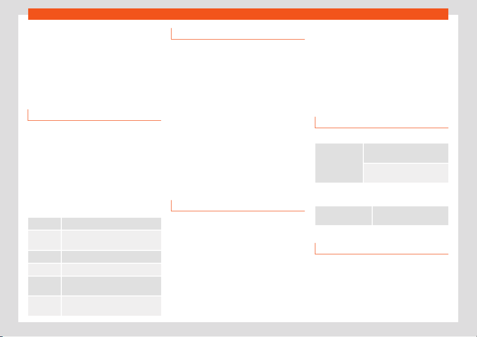
Indications about the technical data
Technical data
Indications about the
t
echnical dat
a
Impor
t
ant inf
ormation
Intr
oduction
The values indicated in the technical data
may diff
er depending on optional equipment
or v
ersion of the model, as w
ell as in the case
of special v
ehicl
es and equipment f
or cert
ain
countries.
The information in the official vehicle docu-
mentation takes precedence at all times.
Abbreviations used in the Technical Speci-
fications section
kW Kilowatt, engine power measurement.
PS
Pferdestärke (horsepower), formerly
used to denote engine power.
rpm, 1/min R
evolutions per minute - engine speed.
Nm Newton metres, unit of engine torque.
CZ
Cetane number, indication of the die-
sel combustion power.
RON
Research octane number
, indication of
the knock resistance of petrol.
Vehicle identification data
Vehicle ID number
The vehicle ID number can be found in the
following pl
aces:
●
In the infotainment system using button >
SETTINGS > Service > Vehicle ID num-
ber.
●
One the vehicle's data label.
●
In front, under the windscreen.
●
To the right in the engine compartment.
Type plate
The type plate is l
ocated on the vehicle’s right
hand door frame. Vehicles for certain export
countries do not have a type plate.
Fuel consumption
Approved consumption values are derived
fr
om measur
ements perf
ormed or supervised
by certified EU l
abor
at
ories, accor
ding to the
legislation in force at the time (for more infor-
mation, see the Publications Office of the Eu-
ropean Union on the EUR-Lex website: © Eu-
ropean Union, http://eur-lex.europa.eu/) and
apply to the specified vehicle characteristics.
The values relating to fuel consumption and
CO
2
emissions can be found in the documen-
tation provided to the purchaser of the vehi-
cle at the time of purchase.
Fuel consumption and CO
2
emissions de-
pend on the equipment/features of each indi-
vidual vehicle, as well as on the driving style,
road conditions, traffic conditions, environ-
mental conditions, load or number of passen-
gers.
Filling capacities
Tank level
Petrol and die-
sel engines
Vehicles with front-wheel drive:
58 l, 7 l reserve
Vehicles with four
-wheel drive:
60 l, 8.5 l reserve
Capacity of the windscreen washer fluid con-
t
ainer
Windscreen washer
fluid container
approx. 3.2 litres
Weights
Load on the roof
The maximum authorised r
oof l
oad f
or your
v
ehicl
e is 75 k
g.
»
389

Technical data
Empty weight, total weight, axle loads
The empt
y w
eight of the v
ehicl
e with driv
er
(75 k
g) w
as calculated according to the (EU)
1230/2012 standard. Optional equipment can
increase the empty weight, which means that
the possible useful load decreases propor-
tionally.
Trailer weight
The maximum permitted drawbar load on the
ball head of the towing device is 80 kg.
WARNING
The values indicated for the maximum per-
mitted weights must not be exceeded.
There is a risk of accident and damage!
390

Indications about the technical data
Engine specifications
Petrol engines 1.4 TSI 1.5 TSI Start-Stop ACT
®
2.0 TSI Start-Stop
Power output in kW (PS) at 1/min 110 (150)/5,000-6,000 110 (150)/5,000-6,000 140 (190)/4,200-6,000
Maximum torque (Nm at 1/min) 250/1,500-3,500 250/1,500-3,500 320/1,500-4,100
No. of cylinders/displacement (cm
3
) 4/1,395 4/1,498 4/1,984
Fuel Super 95 / Normal 91 (with a slight power loss) ROZ
Gearbox DSG manual DSG DSG
Top speed (km/h) 199 (5) 201 (5) 201 (5) 211 (6)
Acceleration from 0-100 km/h (seconds) 9.4 9.7 9.7 8
Maximum authorized weight (kg) (5/7 seats) 2,230 / 2,350 2,220 / 2,330 2,200 / 2,370 2,380 / 2,520
Diesel engines 2.0 TDI
Power output in kW (PS) at 1/min 110 (150)/3,500-4,000 140 (190)/3,500-4,000
Maximum torque (Nm at 1/min) 340/1,750-3,000 400/1,750-3,250
No. of cylinders/displacement (cm
3
) 4/1,968 4/1,968
Fuel Diesel according to standard EN 590, min. 51 CN
Gearbox manual DSG DSG 4Drive
Top speed (km/h) 202 (6) 198 (6) 210 (7)
Acceleration from 0-100 km/h (seconds) 9.8 9.8 8.0
Maximum authorized weight (kg) (5/7 seats) 2,290 / 2,410 2,410 / 2,540 2,410 / 2,550
391
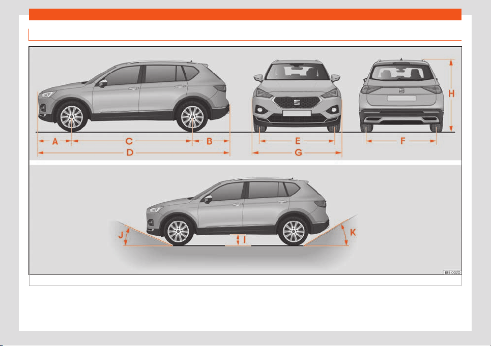
Technical data
Dimensions
Fig. 325
Dimensions.
392

Indications about the technical data
›››
Fig. 325 TARRACO
A Front projection (mm) 926
B Rear projection (mm) 1,019
C Wheelbase (mm) 2,790
D Length (mm) 4,735
E Front
a)
track (mm) 1,585
F Back
a)
track (mm) 1,574
G Width (mm) 1,839
H Height at kerb weight (mm)
1,658
b)
1,6
74
c)
I Ground clearance betw
een the axles (mm) 192
J Front projection angle limited by the bumper maximum 19.1°
K Rear projection angle limited by the bumper maximum 21.4°
Turning radius (m) 11.9
a)
This data will change depending on the type of wheel rim. Values for wheel 215/65 R17 ET38.
b)
Distance to the roof.
c)
Dimension to the roof bars.
393


Index
Index
Numbers and Symbol
s
4Driv
e . . . . . . . . . . . . . . . . . . . . . . . . . . . . . . . . . . . . . .
265
A
ABS
see
Anti-l
ock br
ak
e system . . . . . . . . . . . . . . . . 302
ACC . . . . . . . . . . . . . . . . . . . . . . . . . . . . . . . . . . . . . . . . . 277
radar sensors . . . . . . . . . . . . . . . . . . . . . . . . . . . . . 279
Access aid for the third row . . . . . . . . . . . . . . . . . . 129
Accessories . . . . . . . . . . . . . . . . . . . . . . . . . . . . . . . . . 381
Active cylinder management (ACT)
status indication . . . . . . . . . . . . . . . . . . . . . . . . . . . . 67
Adaptive Cruise Control . . . . . . . . . . . . . . . . . . . . . 277
control and warning lamp . . . . . . . . . . . . . . . . . 278
function to prevent overtaking on the right . 283
indications on the screen . . . . . . . . . . . . . . . . . . 279
malfunction . . . . . . . . . . . . . . . . . . . . . . . . . . . . . . . 277
operating . . . . . . . . . . . . . . . . . . . . . . . . . . . . . . . . . 280
radar sensors . . . . . . . . . . . . . . . . . . . . . . . . . . . . . 279
special driving situations . . . . . . . . . . . . . . . . . . 284
temporarily deactivating . . . . . . . . . . . . . . . . . . 283
AdBlue
control and warning lamps . . . . . . . . . . . . . . . 345
information . . . . . . . . . . . . . . . . . . . . . . . . . . . . . . . 345
loading . . . . . . . . . . . . . . . . . . . . . . . . . . . . . . . . . . . 346
minimum filling capacity . . . . . . . . . . . . . . . . . . 345
specification . . . . . . . . . . . . . . . . . . . . . . . . . . . . . . 346
tank capacity . . . . . . . . . . . . . . . . . . . . . . . . . . . . . 345
Additional heating
see Auxiliary heating . . . . . . . . . . . . . . . . . . . . . . . 161
Adjust
fold down the front passenger’s backrest . . 130
front seats . . . . . . . . . . . . . . . . . . . . . . . . . . . . . . . . . 123
headrest . . . . . . . . . . . . . . . . . . . . . . . . . . . . . . . . . . 126
lights . . . . . . . . . . . . . . . . . . . . . . . . . . . . . . . . . . . . . . 116
rear seat . . . . . . . . . . . . . . . . . . . . . . . . . . . . . . . . . . 125
seats . . . . . . . . . . . . . . . . . . . . . . . . . . . . . . . . . . . . . . . . 12
seat with memory . . . . . . . . . . . . . . . . . . . . . . . . . 128
time . . . . . . . . . . . . . . . . . . . . . . . . . . . . . . . . . . . . . . . . 75
vehicle menu . . . . . . . . . . . . . . . . . . . . . . . . . . . . . . . 82
Adjusting the seat belt . . . . . . . . . . . . . . . . . . . . . . . . 20
Airbags . . . . . . . . . . . . . . . . . . . . . . . . . . . . . . . . . . . . . . . 23
description . . . . . . . . . . . . . . . . . . . . . . . . . . . . . . . . . 24
Airbag system . . . . . . . . . . . . . . . . . . . . . . . . . . . . . . . . 23
activation . . . . . . . . . . . . . . . . . . . . . . . . . . . . . . . . . . 25
control lamp . . . . . . . . . . . . . . . . . . . . . . . . . . . . . . . 25
deactivation of the front airbag . . . . . . . . . . . . . 27
description . . . . . . . . . . . . . . . . . . . . . . . . . . . . . . . . . 24
front airbags . . . . . . . . . . . . . . . . . . . . . . . . . . . . . . . 25
how it works . . . . . . . . . . . . . . . . . . . . . . . . . . . . . . . . 25
Air conditioning
Climatronic . . . . . . . . . . . . . . . . . . . . . . . . . . . . . . . 154
manual air conditioning . . . . . . . . . . . . . . . . . . . 155
usage instructions . . . . . . . . . . . . . . . . . . . . . . . . . 157
Air recirculation . . . . . . . . . . . . . . . . . . . . . . . . . . . . . . 158
Air vents . . . . . . . . . . . . . . . . . . . . . . . . . . . . . . . . . . . . . 158
Alternator
warning lamp . . . . . . . . . . . . . . . . . . . . . . . . . . . . . 360
AM . . . . . . . . . . . . . . . . . . . . . . . . . . . . . . . . . . . . . . . . . . 190
Ambient lighting . . . . . . . . . . . . . . . . . . . . . . . . . . . . . . 117
Android Auto™ . . . . . . . . . . . . . . . . . . . . . . . . . . 183, 185
Anti-lock brake system . . . . . . . . . . . . . . . . . . . . . . 302
Anti-puncture . . . . . . . . . . . . . . . . . . . . . . . . . . . . . 42, 43
Anti-puncture kit . . . . . . . . . . . . . . . . . . . . . . . . . . 41, 42
check after 10 minutes . . . . . . . . . . . . . . . . . . . . . 44
components . . . . . . . . . . . . . . . . . . . . . . . . . . . . . . . 43
inflating the tyre . . . . . . . . . . . . . . . . . . . . . . . . . . . . 43
sealing the tyre . . . . . . . . . . . . . . . . . . . . . . . . . . . . . 43
Anti-puncture set . . . . . . . . . . . . . . . . . . . . . . . . . . . . . 42
Anti-theft alarm system . . . . . . . . . . . . . . . . . . . . . . 96
trailer . . . . . . . . . . . . . . . . . . . . . . . . . . . . . . . . . . . . . 335
Anti-trap function
sunroof . . . . . . . . . . . . . . . . . . . . . . . . . . . . . . . . . . . . 109
sunshade blind (glass roof) . . . . . . . . . . . . . . . . 109
windows . . . . . . . . . . . . . . . . . . . . . . . . . . . . . . . . . . 106
Antifreeze . . . . . . . . . . . . . . . . . . . . . . . . . . . . . . . . . . . 355
App
SEAT Media Control . . . . . . . . . . . . . . . . . . . . . . . 186
Apple CarPlay™ . . . . . . . . . . . . . . . . . . . . . . . . 183, 184
Aspects to think about before starting the ve-
hicle . . . . . . . . . . . . . . . . . . . . . . . . . . . . . . . . . . . . . . . . . 11
ASR
see Traction control system . . . . . . . . . . . . . . . 302
Assistance systems
ACC . . . . . . . . . . . . . . . . . . . . . . . . . . . . . . . . . . . . . . 277
adaptive cruise control . . . . . . . . . . . . . . . . . . . . 277
assisted parting system (Park Assist) . . . . . . 306
Auto Hold function . . . . . . . . . . . . . . . . . . . . . . . . . 301
blind spot detector (BSD) with parking as-
sistant (RCTA) . . . . . . . . . . . . . . . . . . . . . . . . . . . 291
connecting . . . . . . . . . . . . . . . . . . . . . . . . . . . . . . . . . 79
cruise control . . . . . . . . . . . . . . . . . . . . . . . . . . . . . 268
disconnecting . . . . . . . . . . . . . . . . . . . . . . . . . . . . . . 79
driver alert system . . . . . . . . . . . . . . . . . . . . . . . . . . 71
Emergency Assist . . . . . . . . . . . . . . . . . . . . . . . . . 290
emergency braking (Front Assist) . . . . . . . . . . 273
hill descent control (HDC) . . . . . . . . . . . . . . . . . 261
parking aid Plus . . . . . . . . . . . . . . . . . . . . . . . . . . . 315
395

Index
peripheral view system (Top View Cam-
er
a) . . . . . . . . . . . . . . . . . . . . . . . . . . . . . . . . . . . . .
323
Pr
eCr
ash syst
em . . . . . . . . . . . . . . . . . . . . . . . . . . .
22
r
ear cross traffic alert (RCTA) . . . . . . . . . . . . . . 291
rear parking aid . . . . . . . . . . . . . . . . . . . . . . . . . . . 319
road sign detection system messages . . . . . . 72
speed limiter . . . . . . . . . . . . . . . . . . . . . . . . . . . . . . 270
traffic jam assist . . . . . . . . . . . . . . . . . . . . . . . . . . 289
Trailer assist . . . . . . . . . . . . . . . . . . . . . . . . . . . . . . 320
tyre control . . . . . . . . . . . . . . . . . . . . . . . . . . . . . . . 369
tyre pressure loss indicator . . . . . . . . . . . . . . . 369
Assisted start . . . . . . . . . . . . . . . . . . . . . . . . . . . . . . . . . . 51
Audible warning
control and warning lamps . . . . . . . . . . . . . . . . . 79
lights . . . . . . . . . . . . . . . . . . . . . . . . . . . . . . . . . . . . . . 109
unbuckled seat belt . . . . . . . . . . . . . . . . . . . . . . . . 16
Auto Hold . . . . . . . . . . . . . . . . . . . . . . . . . . . . . . . . . . . . 301
Auto Hold Function . . . . . . . . . . . . . . . . . . . . . . . . . . 301
Auto Lock (central locking) . . . . . . . . . . . . . . . . . . . 90
Automatic car wash . . . . . . . . . . . . . . . . . . . . . . . . . 377
disconnecting the Auto Hold function . . . . . . 301
Automatic dipped beam headlight control . . . 110
Automatic gearbox . . . . . . . . . . . . . . . . . . . . . . . . . . 254
control lamp . . . . . . . . . . . . . . . . . . . . . . . . . . . . . . 254
downhill assistant . . . . . . . . . . . . . . . . . . . . . . . . . 258
driving tips . . . . . . . . . . . . . . . . . . . . . . . . . . . . . . . . 256
emergency release of the selector lever. . . 260
kick-down . . . . . . . . . . . . . . . . . . . . . . . . . . . . . . . . . 257
launch-control program . . . . . . . . . . . . . . . . . . 258
operating fault . . . . . . . . . . . . . . . . . . . . . . . . . . . . 257
selector lever lock . . . . . . . . . . . . . . . . . . . . . . . . 255
selector lever positions . . . . . . . . . . . . . . . . . . . . 254
steering wheel with shift paddles . . . . . . . . . 256
tiptronic . . . . . . . . . . . . . . . . . . . . . . . . . . . . . . 254, 256
towing . . . . . . . . . . . . . . . . . . . . . . . . . . . . . . . . . . . . . . 54
AUX-IN . . . . . . . . . . . . . . . . . . . . . . . . . . . . . . . . . . . . . . 244
external audio source . . . . . . . . . . . . . . . . . . . . . 208
Auxiliary heating . . . . . . . . . . . . . . . . . . . . . . . . . . . . . 161
activate . . . . . . . . . . . . . . . . . . . . . . . . . . . . . . . . . . . 163
connecting . . . . . . . . . . . . . . . . . . . . . . . . . . . . . . . . 161
disconnecting . . . . . . . . . . . . . . . . . . . . . . . . . . . . . 161
electricity consumers . . . . . . . . . . . . . . . . . . . . . 164
programming . . . . . . . . . . . . . . . . . . . . . . . . . . . . . . 163
radio-operated remote control . . . . . . . . . . . . 162
remote control range . . . . . . . . . . . . . . . . . . . . . . 162
special characteristics . . . . . . . . . . . . . . . . 161, 164
usage instructions . . . . . . . . . . . . . . . . . . . . . . . . . 164
Average fuel consumption . . . . . . . . . . . . . . . . . . . . 65
B
Backrest of the rear seat
folding . . . . . . . . . . . . . . . . . . . . . . . . . . . . . . . . . . . . . 131
raise . . . . . . . . . . . . . . . . . . . . . . . . . . . . . . . . . . . . . . . 131
Bag hooks . . . . . . . . . . . . . . . . . . . . . . . . . . . . . . . 141, 148
Battery . . . . . . . . . . . . . . . . . . . . . . . . . . . . . . . . . . . . . . . 88
change on the remote control (independ-
ent heating) . . . . . . . . . . . . . . . . . . . . . . . . . . . . . 162
Before starting the vehicle . . . . . . . . . . . . . . . . . . . . . 11
Belt tightening . . . . . . . . . . . . . . . . . . . . . . . . . . . . . . . . 21
Bicycle carrier
fitting onto the coverable tow hook . . . . . . . 340
max. load rating . . . . . . . . . . . . . . . . . . . . . . . . . . 340
Biodiesel . . . . . . . . . . . . . . . . . . . . . . . . . . . . . . . . . . . . 345
Blind spot detector (BSD) . . . . . . . . . . . . . . . 291, 292
control lamps . . . . . . . . . . . . . . . . . . . . . . . . . . . . . 292
driving situations . . . . . . . . . . . . . . . . . . . . . . . . . . 295
how it works . . . . . . . . . . . . . . . . . . . . . . . . . . . . . . . 293
indication on the exterior mirror . . . . . . . . . . . 293
malfunction . . . . . . . . . . . . . . . . . . . . . . . . . . . . . . . 291
trailer . . . . . . . . . . . . . . . . . . . . . . . . . . . . . . . . . . . . . 297
Bluetooth®
connect audio source . . . . . . . . . . . . . . . . . . . . . 208
Bonnet . . . . . . . . . . . . . . . . . . . . . . . . . . . . . . . . . 349, 351
opening and closing . . . . . . . . . . . . . . . . . . . . . . 350
Brake fluid . . . . . . . . . . . . . . . . . . . . . . . . . . . . . . . . . . . 357
Brakes . . . . . . . . . . . . . . . . . . . . . . . . . . . . . . . . . . . . . . 298
brake fluid . . . . . . . . . . . . . . . . . . . . . . . . . . . . . . . . . 357
brake servo . . . . . . . . . . . . . . . . . . . . . . . . . . . . . . . 298
braking assistant . . . . . . . . . . . . . . . . . . . . . . . . . . 302
electronic parking brake . . . . . . . . . . . . . . . . . . 299
emergency brake function . . . . . . . . . . . . . . . . 300
new brake pads . . . . . . . . . . . . . . . . . . . . . . . . . . . 298
Braking assistant . . . . . . . . . . . . . . . . . . . . . . . . . . . . 302
Braking system
warning lamp . . . . . . . . . . . . . . . . . . . . . . . . . . . . . 297
BSD
see blind spot detector (BSD) . . . . . . . . . . . . . 291
BSD Plus . . . . . . . . . . . . . . . . . . . . . . . . . . . . . . . . . . . . 288
C
Camera
cleaning . . . . . . . . . . . . . . . . . . . . . . . . . . . . . . . . . . . . 74
Lane Assist . . . . . . . . . . . . . . . . . . . . . . . . . . . . . . . . 286
Capacities
AdBlue tank . . . . . . . . . . . . . . . . . . . . . . . . . . . . . . . 345
window washer water . . . . . . . . . . . . . . . . . . . . . 357
Care
see Cleaning the vehicle . . . . . . . . . . . . . . . . . . 376
Catalytic converter . . . . . . . . . . . . . . . . . . . . . . . . . 348
Central armrests . . . . . . . . . . . . . . . . . . . . . . . . . . . . 133
Central locking . . . . . . . . . . . . . . . . . . . . . . . . . . . . . . . 89
anti-theft alarm . . . . . . . . . . . . . . . . . . . . . . . . . . . . 96
central locking switch . . . . . . . . . . . . . . . . . . . . . . 92
emergency lock . . . . . . . . . . . . . . . . . . . . . . . . . . . . 99
Keyless Access . . . . . . . . . . . . . . . . . . . . . . . . . . . . . 92
396

Index
remote control key . . . . . . . . . . . . . . . . . . . . . . . . . . 91
sel
ectiv
e unl
ocking syst
em . . . . . . . . . . . . . . . . .
91
settings . . . . . . . . . . . . . . . . . . . . . . . . . . . . . . . . . . . .
90
Cet
ane index (diesel fuel) . . . . . . . . . . . . . . . . . . . 345
Change the wiper blades . . . . . . . . . . . . . . . . . . . . 49
Changing a wheel . . . . . . . . . . . . . . . . . . . . . . . . . . . . 45
subsequent work . . . . . . . . . . . . . . . . . . . . . . . . . . . 49
wheel nuts . . . . . . . . . . . . . . . . . . . . . . . . . . . . . . . . . 46
Changing parts . . . . . . . . . . . . . . . . . . . . . . . . . . . . . 381
Checking levels
engine compartment . . . . . . . . . . . . . . . . . . . . . . 351
Check lists
reverse assist (Rear View) . . . . . . . . . . . . . . . . . 329
Childproof locks
electric windows . . . . . . . . . . . . . . . . . . . . . . . . . . 104
Child seats
group classification . . . . . . . . . . . . . . . . . . . . . . . . . 31
ISOFIX/i-Size system . . . . . . . . . . . . . . . . . . . . . . . . 37
ISOFIX system . . . . . . . . . . . . . . . . . . . . . . . . . . . . . . 35
safety instructions . . . . . . . . . . . . . . . . . . . . . . . . . . 32
securing with the seat belt . . . . . . . . . . . . . . . . . 39
Top Tether system . . . . . . . . . . . . . . . . . . . . . . 35, 38
Cleaning the vehicle
high pressure cleaning equipment . . . . . . . . 376
special care . . . . . . . . . . . . . . . . . . . . . . . . . . . . . . 380
vehicle exterior . . . . . . . . . . . . . . . . . . . . . . . . . . . . 378
vehicle interior . . . . . . . . . . . . . . . . . . . . . . . . . . . . 379
wash the vehicle . . . . . . . . . . . . . . . . . . . . . . . . . . 376
Climate control
auxiliary heating . . . . . . . . . . . . . . . . . . . . . . . . . . . 161
controls . . . . . . . . . . . . . . . . . . . . . . . . . . . . . . . . . . . 157
setting the temperature . . . . . . . . . . . . . . . . . . . . 157
Climatronic . . . . . . . . . . . . . . . . . . . . . . . . . . . . . . . . . . 154
Clocks
set the time . . . . . . . . . . . . . . . . . . . . . . . . . . . . . . . . . 75
Closing . . . . . . . . . . . . . . . . . . . . . . . . . . . . . . . . . . . . . . . 89
bonnet . . . . . . . . . . . . . . . . . . . . . . . . . . . . . . . . . . . . 350
rear lid . . . . . . . . . . . . . . . . . . . . . . . . . . . . . . . . . . . . . 101
sunroof . . . . . . . . . . . . . . . . . . . . . . . . . . . . . . . . . . . . 107
sunshade blind (glass roof) . . . . . . . . . . . . . . . . 108
windows . . . . . . . . . . . . . . . . . . . . . . . . . . . . . . . . . . 104
Clutch (lamp) . . . . . . . . . . . . . . . . . . . . . . . . . . . . . . . 259
Coming Home . . . . . . . . . . . . . . . . . . . . . . . . . . . . . . . 114
Communication between the Infotainment
System and mobile devices . . . . . . . . . . . . . . . 180
Connectivity . . . . . . . . . . . . . . . . . . . . . . . . . . . . . . . . 180
Full Link . . . . . . . . . . . . . . . . . . . . . . . . . . . . . . . . . . . 180
SEAT Media Control . . . . . . . . . . . . . . . . . . . . . . . 186
WLAN access point . . . . . . . . . . . . . . . . . . . . . . . . 187
Connectivity Box . . . . . . . . . . . . . . . . . . . . . . . . . . . . 244
Connectors
faults . . . . . . . . . . . . . . . . . . . . . . . . . . . . . . . . . . . . . . 151
Control and warning lamps . . . . . . . . . . . . . . . . . . . 79
adaptive cruise control . . . . . . . . . . . . . . . . . . . . 278
adBlue . . . . . . . . . . . . . . . . . . . . . . . . . . . . . . . . . . . . 345
airbags . . . . . . . . . . . . . . . . . . . . . . . . . . . . . . . . . . . . . 27
airbag system . . . . . . . . . . . . . . . . . . . . . . . . . . . . . . 25
alternator . . . . . . . . . . . . . . . . . . . . . . . . . . . . . . . . . 360
anti-lock brake system ABS . . . . . . . . . . . . . . . 302
ASR . . . . . . . . . . . . . . . . . . . . . . . . . . . . . . . . . . 302, 304
audible warning . . . . . . . . . . . . . . . . . . . . . . . . . . . . 79
blind spot detector (BSD) . . . . . . . . . . . . . . . . . 292
braking system . . . . . . . . . . . . . . . . . . . . . . . . . . . . 297
cruise control (GRA) . . . . . . . . . . . . . . . . . . . . . . 268
diesel preheating system . . . . . . . . . . . . . . . . . 347
EDL . . . . . . . . . . . . . . . . . . . . . . . . . . . . . . . . . . . . . . . 302
electromechanical steering . . . . . . . . . . . . . . . 262
electronic parking brake . . . . . . . . . . . . . . . . . . 297
emissions control . . . . . . . . . . . . . . . . . . . . . . . . . 347
engine coolant . . . . . . . . . . . . . . . . . . . . . . . . . . . . . 76
engine management . . . . . . . . . . . . . . . . . . . . . . 347
engine oil . . . . . . . . . . . . . . . . . . . . . . . . . . . . . . . . . 353
ESC . . . . . . . . . . . . . . . . . . . . . . . . . . . . . . . . . 302, 304
fuel reserve . . . . . . . . . . . . . . . . . . . . . . . . . . . . . . . . . 76
gear change . . . . . . . . . . . . . . . . . . . . . . . . . . . . . . 260
hill descent control . . . . . . . . . . . . . . . . . . . . . . . . 261
Lane Assist . . . . . . . . . . . . . . . . . . . . . . . . . . . . . . . . 286
lights . . . . . . . . . . . . . . . . . . . . . . . . . . . . . . . . . . . . . . 109
particulate filter . . . . . . . . . . . . . . . . . . . . . . 347, 348
press on the brake . . . . . . . . . . . . . . . . . . . . 273, 278
rear cross traffic alert (RCTA) . . . . . . . . . . . . . 292
refuelling . . . . . . . . . . . . . . . . . . . . . . . . . . . . . . 76, 342
remote control (independent heating) . . . . . 162
replacement . . . . . . . . . . . . . . . . . . . . . . . . . . . . . . 254
seat belt . . . . . . . . . . . . . . . . . . . . . . . . . . . . . . . . . . . . 16
speed limiter . . . . . . . . . . . . . . . . . . . . . . . . . . . . . . 270
Start-Stop . . . . . . . . . . . . . . . . . . . . . . . . . . . . . . . . 250
steering column lock . . . . . . . . . . . . . . . . . . . . . . 262
tow hook . . . . . . . . . . . . . . . . . . . . . . . . . . . . . . . . . . 339
tyre pressure loss indicator . . . . . . . . . . . . . . . 369
Controls
rear seat . . . . . . . . . . . . . . . . . . . . . . . . . . . . . . . . . . 125
Controls and displays
overview . . . . . . . . . . . . . . . . . . . . . . . . . . . . . . . . . . . 63
Controls on the steering wheel . . . . . . . . . . . . . . . 85
Convenience close function
windows . . . . . . . . . . . . . . . . . . . . . . . . . . . . . . . . . . 105
Convenience open function
windows . . . . . . . . . . . . . . . . . . . . . . . . . . . . . . . . . . 105
Cooling system
check the coolant . . . . . . . . . . . . . . . . . . . . . . . . 356
refilling coolant . . . . . . . . . . . . . . . . . . . . . . . . . . . 356
Copyright . . . . . . . . . . . . . . . . . . . . . . . . . . . . . . . . . . . 198
information . . . . . . . . . . . . . . . . . . . . . . . . . . . . . . . . 174
397

Index
Correct sitting position . . . . . . . . . . . . . . . . . . . . . . . . 12
driv
er . . . . . . . . . . . . . . . . . . . . . . . . . . . . . . . . . . . . . . .
12
Cruise contr
ol . . . . . . . . . . . . . . . . . . . . . . . . . . . . . . .
268
contr
ol and w
arning l
amp . . . . . . . . . . . . . . . . 268
operation . . . . . . . . . . . . . . . . . . . . . . . . . . . . . . . . . 270
D
DAB . . . . . . . . . . . . . . . . . . . . . . . . . . . . . . . . . . . . . . . . . 190
see: RADIO . . . . . . . . . . . . . . . . . . . . . . . . . . . . . . . . 192
Dangers of not using the seat belt . . . . . . . . . . . . 18
Data label . . . . . . . . . . . . . . . . . . . . . . . . . . . . . . . . . . 389
Data transfer . . . . . . . . . . . . . . . . . . . . . . . . . . . . . . . . 180
Deactivation of cylinders
see Active cylinder management (ACT) . . . . 67
Deactivation of the front airbag . . . . . . . . . . . . . . . 27
Delayed shutdown (Infotainment system) . . . 170
Diesel
engine oil . . . . . . . . . . . . . . . . . . . . . . . . . . . . . . . . . 352
particulate filter . . . . . . . . . . . . . . . . . . . . . . . . . . . 348
refuelling . . . . . . . . . . . . . . . . . . . . . . . . . . . . . . . . . 345
Display of road signs on the instrument panel
activate . . . . . . . . . . . . . . . . . . . . . . . . . . . . . . . . . . . . 73
deactivate . . . . . . . . . . . . . . . . . . . . . . . . . . . . . . . . . . 73
Disposal
seat belt tensioners . . . . . . . . . . . . . . . . . . . . . . . . . 21
Distance control
see Adaptive Cruise Control . . . . . . . . . . . . . . . 277
Door cylinder . . . . . . . . . . . . . . . . . . . . . . . . . . . . . . . . 99
Door handle . . . . . . . . . . . . . . . . . . . . . . . . . . . . . . . . . . 99
Door lock . . . . . . . . . . . . . . . . . . . . . . . . . . . . . . . . . . . . 99
Doors . . . . . . . . . . . . . . . . . . . . . . . . . . . . . . . . . . . . . . . . 98
child lock . . . . . . . . . . . . . . . . . . . . . . . . . . . . . . . . . 100
Downhill assistance function . . . . . . . . . . . . . . . . 258
Downhill assistant . . . . . . . . . . . . . . . . . . . . . . . . . . . 258
Drawers . . . . . . . . . . . . . . . . . . . . . . . . . . . . . . . . . . . . . 148
Drink holder
bottle holder . . . . . . . . . . . . . . . . . . . . . . . . . . . . . . 148
in the front part of the centre console . . . . . 149
in the rear central armrest . . . . . . . . . . . . . . . . . 150
Driver
see Correct sitting position . . . . . . . . . . . . . . . . . 12
Driver alert system . . . . . . . . . . . . . . . . . . . . . . . . . . . . 71
Driving
driving on flooded roads . . . . . . . . . . . . . . . . . . 268
economical . . . . . . . . . . . . . . . . . . . . . . . . . . . . . . . 266
parking on inclines . . . . . . . . . . . . . . . . . . . . . . . . 306
park on upward slopes . . . . . . . . . . . . . . . . . . . 306
safe . . . . . . . . . . . . . . . . . . . . . . . . . . . . . . . . . . . . . . . . . 11
trips abroad . . . . . . . . . . . . . . . . . . . . . . . . . . 116, 268
with trailer . . . . . . . . . . . . . . . . . . . . . . . . . . . . . . . . . 337
Driving data . . . . . . . . . . . . . . . . . . . . . . . . . . . . . . . . . . 69
Driving data indicator . . . . . . . . . . . . . . . . . . . . . . . . 69
Driving mode. . . . . . . . . . . . . . . . . . . . . . . . . . . . . . . . 264
Driving on flooded roads . . . . . . . . . . . . . . . . . . . . 268
Driving profile . . . . . . . . . . . . . . . . . . . . . . . . . . . . . . . 264
DSG . . . . . . . . . . . . . . . . . . . . . . . . . . . . . . . . . . . . . . . . 254
Duplicate keys . . . . . . . . . . . . . . . . . . . . . . . . . . . . . . . 87
Dust and pollen filter . . . . . . . . . . . . . . . . . . . . . . . . 152
DVD . . . . . . . . . . . . . . . . . . . . . . . . . . . . . . . . . . . . 206, 212
settings . . . . . . . . . . . . . . . . . . . . . . . . . . . . . . . . . . . . 213
Dynamic headlight range control . . . . . . . . . . . . 116
E
E10
see Ethanol (fuel) . . . . . . . . . . . . . . . . . . . . . . . . . 344
Easy Connect . . . . . . . . . . . . . . . . . . . . . . . . . . . . . . . . 82
Easy Open . . . . . . . . . . . . . . . . . . . . . . . . . . . . . . . . . . . 92
special characteristics . . . . . . . . . . . . . . . . . . . . 103
EDL
see Electronic differential lock . . . . . . . . . . . . 302
Electric
windows . . . . . . . . . . . . . . . . . . . . . . . . . . . . . . . . . . 104
Electric devices . . . . . . . . . . . . . . . . . . . . . . . . . . . . . 150
Electric windows . . . . . . . . . . . . . . . . . . . . . . . . . . . . 104
Electrolyte . . . . . . . . . . . . . . . . . . . . . . . . . . . . . . . . . . 360
Electromechanical steering . . . . . . . . . . . . . . . . . 262
lamp . . . . . . . . . . . . . . . . . . . . . . . . . . . . . . . . . . . . . . 262
Electronic differential lock . . . . . . . . . . . . . . . . . . . 302
Electronic engine torque management
(XDS) . . . . . . . . . . . . . . . . . . . . . . . . . . . . . . . . . . . . . 303
Electronic immobilizer . . . . . . . . . . . . . . . . . . . 99, 249
Electronic parking brake . . . . . . . . . . . . . . . . . . . . 299
lamp . . . . . . . . . . . . . . . . . . . . . . . . . . . . . . . . . . . . . . 297
Electronic self-locking . . . . . . . . . . . . . . . . . . . . . . 302
Electronic Stability Control (ESC) . . . . . . . . . . . 302
Emergencies . . . . . . . . . . . . . . . . . . . . . . . . . . . . . . . . . . 41
anti-puncture kit . . . . . . . . . . . . . . . . . . . . . . . . . . . . 42
bulbs . . . . . . . . . . . . . . . . . . . . . . . . . . . . . . . . . . . . . . . 61
changing a wheel . . . . . . . . . . . . . . . . . . . . . . . . . . 45
changing the battery . . . . . . . . . . . . . . . . . . . . . 360
emergency vehicle towing . . . . . . . . . . . . . . . . . 54
hazard warning lights . . . . . . . . . . . . . . . . . . . . . . 115
jump leads . . . . . . . . . . . . . . . . . . . . . . . . . . . . . . . . . . 51
replace a blown fuse . . . . . . . . . . . . . . . . . . . . . . . 59
vehicle tool kit . . . . . . . . . . . . . . . . . . . . . . . . . . . . . . 41
Emergency Assist . . . . . . . . . . . . . . . . . . . . . . . . . . . 290
connecting . . . . . . . . . . . . . . . . . . . . . . . . . . . . . . . 290
disconnecting . . . . . . . . . . . . . . . . . . . . . . . . . . . . 290
see Emergency Assistant . . . . . . . . . . . . . . . . . 290
Emergency brake function . . . . . . . . . . . . . . . . . . 300
Emergency braking assist system
indications on the screen . . . . . . . . . . . . . . . . . . 273
malfunction . . . . . . . . . . . . . . . . . . . . . . . . . . . . . . . 273
operation . . . . . . . . . . . . . . . . . . . . . . . . . . . . . . . . . 276
radar sensors . . . . . . . . . . . . . . . . . . . . . . . . . . . . . 275
398

Index
system limitations . . . . . . . . . . . . . . . . . . . . . . . . . 277
t
empor
arily deactiv
ating . . . . . . . . . . . . . . . . . .
276
Emer
gency br
aking w
arning . . . . . . . . . . . . . . . . . 116
Emergency call . . . . . . . . . . . . . . . . . . . . . . . . . . . . . . . 41
Emergency call service . . . . . . . . . . . . . . . . . . . . . . . 41
Emergency locking of the front passenger
door . . . . . . . . . . . . . . . . . . . . . . . . . . . . . . . . . . . . . . . 99
Emergency opening
driver's door . . . . . . . . . . . . . . . . . . . . . . . . . . . . . . . 99
rear lid . . . . . . . . . . . . . . . . . . . . . . . . . . . . . . . . . . . . 104
Emergency operation
front passenger door . . . . . . . . . . . . . . . . . . . . . . . 99
gear selector lever . . . . . . . . . . . . . . . . . . . . . . . . 260
Emissions control system
AdBlue . . . . . . . . . . . . . . . . . . . . . . . . . . . . . . . . . . . . 345
catalytic converter . . . . . . . . . . . . . . . . . . . . . . . 348
control lamp . . . . . . . . . . . . . . . . . . . . . . . . . . . . . . 347
particulate filter . . . . . . . . . . . . . . . . . . . . . . . . . . . 348
Energy management . . . . . . . . . . . . . . . . . . . . . . . . 361
Engine
assisted start . . . . . . . . . . . . . . . . . . . . . . . . . . . . . . . 51
noises . . . . . . . . . . . . . . . . . . . . . . . . . . . . . . . . . . . . . 247
running in . . . . . . . . . . . . . . . . . . . . . . . . . . . . . . . . . 265
Start-Stop system . . . . . . . . . . . . . . . . . . . . . . . . 250
start (driver instructions with the mechani-
cal contact) . . . . . . . . . . . . . . . . . . . . . . . . . . . . 249
Engine and ignition
automatic ignition disconnection . . . . . . . . . 246
emergency start . . . . . . . . . . . . . . . . . . . . . . . . . . 249
My Beat . . . . . . . . . . . . . . . . . . . . . . . . . . . . . . . . . . . 250
preheat the engine . . . . . . . . . . . . . . . . . . . . . . . . 247
starting the engine . . . . . . . . . . . . . . . . . . . . . . . . 247
starting the engine with Press & Drive . . . . . 247
switching off the engine . . . . . . . . . . . . . . . . . . . 248
Engine compartment . . . . . . . . . . . . . . . . . . . 349, 351
battery . . . . . . . . . . . . . . . . . . . . . . . . . . . . . . . . . . . 358
brake fluid . . . . . . . . . . . . . . . . . . . . . . . . . . . . . . . . . 357
coolant . . . . . . . . . . . . . . . . . . . . . . . . . . . . . . 355, 356
engine oil . . . . . . . . . . . . . . . . . . . . . . . . . . . . . . . . . 354
opening and closing . . . . . . . . . . . . . . . . . . . . . . 350
safety instructions . . . . . . . . . . . . . . . . . . . . . . . . 349
window washer tank . . . . . . . . . . . . . . . . . . . . . . 357
Engine coolant . . . . . . . . . . . . . . . . . . . . . . . . . . . . . . 355
check the level . . . . . . . . . . . . . . . . . . . . . . . . . . . . 356
control lamp . . . . . . . . . . . . . . . . . . . . . . . . . . . . . . . 76
G12evo . . . . . . . . . . . . . . . . . . . . . . . . . . . . . . . . . . . . 355
G12 plus-plus . . . . . . . . . . . . . . . . . . . . . . . . . . . . . 355
G13 . . . . . . . . . . . . . . . . . . . . . . . . . . . . . . . . . . . . . . . 355
specifications . . . . . . . . . . . . . . . . . . . . . . . . . . . . . 355
temperature indicator . . . . . . . . . . . . . . . . . . . . . . 76
warning lamp . . . . . . . . . . . . . . . . . . . . . . . . . . . . . . 76
Engine failure
control lamp . . . . . . . . . . . . . . . . . . . . . . . . . . . . . . 347
Engine management . . . . . . . . . . . . . . . . . . . . . . . . 347
control lamp . . . . . . . . . . . . . . . . . . . . . . . . . . . . . . 347
Engine oil
change . . . . . . . . . . . . . . . . . . . . . . . . . . . . . . 352, 354
checking the oil level . . . . . . . . . . . . . . . . . . . . . . 353
consumption . . . . . . . . . . . . . . . . . . . . . . . . . . . . . . 353
dipstick . . . . . . . . . . . . . . . . . . . . . . . . . . . . . . . . . . . 353
inspection service . . . . . . . . . . . . . . . . . . . . . . . . . 352
maintenance frequencies . . . . . . . . . . . . . . . . . 352
refill . . . . . . . . . . . . . . . . . . . . . . . . . . . . . . . . . . . . . . . 354
specifications . . . . . . . . . . . . . . . . . . . . . . . . 352, 353
Engine oil pressure
control lamp . . . . . . . . . . . . . . . . . . . . . . . . . . . . . . 353
Engine specifications . . . . . . . . . . . . . . . . . . . . . . . . 391
Environment
ecological driving . . . . . . . . . . . . . . . . . . . . . . . . . 266
environmental compatibility . . . . . . . . . . . . . . 384
refuelling . . . . . . . . . . . . . . . . . . . . . . . . . . . . . . . . . . 342
Environmental tip
refuelling . . . . . . . . . . . . . . . . . . . . . . . . . . . . . . . . . . 342
Equipment . . . . . . . . . . . . . . . . . . . . . . . . . . . . . . . . . . . 381
ESC
electronic stability control (ESC) . . . . . . . . . . 302
multi-collision brake . . . . . . . . . . . . . . . . . . . . . . 303
Sport mode . . . . . . . . . . . . . . . . . . . . . . . . . . . . . . . 304
Ethanol (fuel) . . . . . . . . . . . . . . . . . . . . . . . . . . . . . . . 344
Event Data Recorder . . . . . . . . . . . . . . . . . . . . . . . . 384
Exhaust gases . . . . . . . . . . . . . . . . . . . . . . . . . . . . . . . 347
Exterior mirrors
driving with a trailer . . . . . . . . . . . . . . . . . . . . . . . 334
folding . . . . . . . . . . . . . . . . . . . . . . . . . . . . . . . . . . . . . 121
heated . . . . . . . . . . . . . . . . . . . . . . . . . . . . . . . . . . . . . 121
settings . . . . . . . . . . . . . . . . . . . . . . . . . . . . . . . . . . . . 121
Exterior view . . . . . . . . . . . . . . . . . . . . . . . . . . . . . . . . . . . 7
External antenna . . . . . . . . . . . . . . . . . . . . . . . . . . . . 382
F
Fabrics: clean . . . . . . . . . . . . . . . . . . . . . . . . . . . . . . . 379
Factors that have a negative influence on
safe driving . . . . . . . . . . . . . . . . . . . . . . . . . . . . . . . . . . 11
Fastening rings . . . . . . . . . . . . . . . . . . . . . . . . . . . . . . 139
Filling capacities
fuel tank . . . . . . . . . . . . . . . . . . . . . . . . . . . . . . . . . . 389
window washer tank . . . . . . . . . . . . . . . . . . . . . . 389
Filling the tank . . . . . . . . . . . . . . . . . . . . . . . . . . . . . . . 342
FM . . . . . . . . . . . . . . . . . . . . . . . . . . . . . . . . . . . . . . . . . . 190
Fog lights with cornering light function . . . . . . . 114
Folding table . . . . . . . . . . . . . . . . . . . . . . . . . . . . . . . . . 147
399

Index
Four-wheel drive . . . . . . . . . . . . . . . . . . . . . . . . . . . . 265
sno
w chains . . . . . . . . . . . . . . . . . . . . . . . . . . . . . .
266
t
o
wing . . . . . . . . . . . . . . . . . . . . . . . . . . . . . . . . . . . . . .
54
wint
er t
yres . . . . . . . . . . . . . . . . . . . . . . . . . . . . . . . 266
Frequency band
AM . . . . . . . . . . . . . . . . . . . . . . . . . . . . . . . . . . . . . . . . 190
change . . . . . . . . . . . . . . . . . . . . . . . . . . . . . . . . . . . 190
DAB . . . . . . . . . . . . . . . . . . . . . . . . . . . . . . . . . . . . . . . 190
FM . . . . . . . . . . . . . . . . . . . . . . . . . . . . . . . . . . . . . . . . 190
Front airbags . . . . . . . . . . . . . . . . . . . . . . . . . . . . . . . . . 25
Front Assist
see Emergency braking assist system . . . . . 273
Front passenger front airbag
control lamp . . . . . . . . . . . . . . . . . . . . . . . . . . . . . . . 25
Fuel
diesel . . . . . . . . . . . . . . . . . . . . . . . . . . . . . . . . . . . . . 345
ethanol . . . . . . . . . . . . . . . . . . . . . . . . . . . . . . . . . . . 344
fuel gauge . . . . . . . . . . . . . . . . . . . . . . . . . . . . . . . . . 76
identification . . . . . . . . . . . . . . . . . . . . . . . . . . . . . . 343
petrol . . . . . . . . . . . . . . . . . . . . . . . . . . . . . . . . . . . . . 343
refuelling . . . . . . . . . . . . . . . . . . . . . . . . . . . . . . . . . . 342
saving . . . . . . . . . . . . . . . . . . . . . . . . . . . . . . . . . . . . 266
Fuel consumption
inertia disconnection . . . . . . . . . . . . . . . . . . . . . 266
why does consumption increase? . . . . . . . . . 347
Fuel gauge . . . . . . . . . . . . . . . . . . . . . . . . . . . . . . . . . . . 76
control lamp . . . . . . . . . . . . . . . . . . . . . . . . . . . . . . . 76
Fuel tank cap
opening and closing . . . . . . . . . . . . . . . . . . . . . . 342
Fuel tank flap
opening and closing . . . . . . . . . . . . . . . . . . . . . . 342
Full Link . . . . . . . . . . . . . . . . . . . . . . . . . . . . . . . . . . . . . . 180
pairing . . . . . . . . . . . . . . . . . . . . . . . . . . . . . . . . . . . . 183
settings . . . . . . . . . . . . . . . . . . . . . . . . . . . . . . . . . . . . 183
Function buttons . . . . . . . . . . . . . . . . . . . . . . . . . . . . . 171
Fuses . . . . . . . . . . . . . . . . . . . . . . . . . . . . . . . . . . . . . . . . . 57
colour coded . . . . . . . . . . . . . . . . . . . . . . . . . . . . . . . 58
fuse box . . . . . . . . . . . . . . . . . . . . . . . . . . . . . . . . 58, 59
preparations for replacing fuses . . . . . . . . . . . . 59
recognise blown fuses . . . . . . . . . . . . . . . . . . . . . 59
replace . . . . . . . . . . . . . . . . . . . . . . . . . . . . . . . . . . . . 59
G
GALA (speed-dependent volume) . . . . . . . . . . . 176
Gear-change recommendation . . . . . . . . . . . . . 261
Gearbox DSG
see Automatic gearbox . . . . . . . . . . . . . . . . . . . 254
Gear change
engage the gears (manual change) . . . . . . 253
manual gearbox . . . . . . . . . . . . . . . . . . . . . . . . . . 253
Gear indication . . . . . . . . . . . . . . . . . . . . . . . . . . . . . . 261
Glasses case . . . . . . . . . . . . . . . . . . . . . . . . . . . . . . . . 147
Glove compartment . . . . . . . . . . . . . . . . . . . . . . . . . 146
H
Handbrake
see Electronic parking brake . . . . . . . . . . . . . . 299
Hangers . . . . . . . . . . . . . . . . . . . . . . . . . . . . . . . . . . . . . 148
Hazard warning lights . . . . . . . . . . . . . . . . . . . . . . . . 115
HDC
see Hill descent control (HDC). . . . . . . . . . . . . 261
Head-on collisions and the laws of physics . . . 18
Head-protection airbags
safety instructions . . . . . . . . . . . . . . . . . . . . . . . . . . 30
Headlights
trips abroad . . . . . . . . . . . . . . . . . . . . . . . . . . . . . . . 116
Headrest . . . . . . . . . . . . . . . . . . . . . . . . . . . . 125, 126, 127
Heating and fresh air . . . . . . . . . . . . . . . . . . . . . . . . 155
Hill descent control (HDC).
control lamp . . . . . . . . . . . . . . . . . . . . . . . . . . . . . . 261
Horn . . . . . . . . . . . . . . . . . . . . . . . . . . . . . . . . . . . . . . . . . . 63
I
Identification of fuels . . . . . . . . . . . . . . . . . . . . . . . . 343
Identifying letters on engine (LDM)
display . . . . . . . . . . . . . . . . . . . . . . . . . . . . . . . . . . . . . 69
Inertia mode . . . . . . . . . . . . . . . . . . . . . . . . . . . . . . . . 259
Information profiles . . . . . . . . . . . . . . . . . . . . . . . . . . . 65
Infotainment buttons . . . . . . . . . . . . . . . . . . . . . . . . 170
Infotainment System . . . . . . . . . . . . . . . . . . . . . . . . . 165
automatic playback (SCAN) . . . . . . . . . . . . . . 195
AUX-IN . . . . . . . . . . . . . . . . . . . . . . . . . . . . . . . . . . . . 208
Bluetooth® audio . . . . . . . . . . . . . . . . . . . . . . . . . 208
Bluetooth® settings . . . . . . . . . . . . . . . . . . . . . . . 242
CD or DVD player . . . . . . . . . . . . . . . . . . . . . . . . 206
change the volume . . . . . . . . . . . . . . . . . . . . . . . . 171
checkboxes . . . . . . . . . . . . . . . . . . . . . . . . . . . . . . . . 171
DVD . . . . . . . . . . . . . . . . . . . . . . . . . . . . . . . . . . . . . . . 212
DVD settings . . . . . . . . . . . . . . . . . . . . . . . . . . . . . . 213
factory settings . . . . . . . . . . . . . . . . . . . . . . . . . . . . 174
FM, AM, DAB settings) . . . . . . . . . . . . . . . . . . . . . 196
function buttons . . . . . . . . . . . . . . . . . . . . . . . . . . . 171
general instructions for use . . . . . . . . . . . . . . . . 170
image settings . . . . . . . . . . . . . . . . . . . . . . . . . . . . . 214
images main menu . . . . . . . . . . . . . . . . . . . . . . . . 213
infotainment buttons . . . . . . . . . . . . . . . . . . . . . . 170
initial configuration . . . . . . . . . . . . . . . . . . . . . . . . 174
input window . . . . . . . . . . . . . . . . . . . . . . . . . . . . . . 172
Internet access . . . . . . . . . . . . . . . . . . . . . . . . . . . . 188
Jukebox (SSD) . . . . . . . . . . . . . . . . . . . . . . . . . . . . 209
Media settings . . . . . . . . . . . . . . . . . . . . . . . . . . . . . 214
memory card . . . . . . . . . . . . . . . . . . . . . . . . . . . . . 207
mute . . . . . . . . . . . . . . . . . . . . . . . . . . . . . . . . . . . . . . . 171
400

Index
navigation . . . . . . . . . . . . . . . . . . . . . . . . . . . . . . . . . 215
navigation settings . . . . . . . . . . . . . . . . . . . . . . . .
225
on-scr
een k
eyboar
d . . . . . . . . . . . . . . . . . . . . . . .
1
7
2
overview of the unit . . . . . . . . . . . . . . . . . . . . . . . . 167
phone settings . . . . . . . . . . . . . . . . . . . . . . . . . . . . 242
preset buttons . . . . . . . . . . . . . . . . . . . . . . . . . . . . . 193
Radio mode . . . . . . . . . . . . . . . . . . . . . . . . . . . . . . . 190
road signs indication . . . . . . . . . . . . . . . . . . . . . . 224
rotary/push buttons . . . . . . . . . . . . . . . . . . . . . . . 170
safety instructions . . . . . . . . . . . . . . . . . . . . . . . . . 165
scroll button . . . . . . . . . . . . . . . . . . . . . . . . . . . . . . . 172
scroll (screen) . . . . . . . . . . . . . . . . . . . . . . . . . . . . . 172
search on lists . . . . . . . . . . . . . . . . . . . . . . . . . . . . . 172
selecting, tuning and saving stations . . . . . . 194
share a WLAN connection . . . . . . . . . . . . . . . . . 188
sound distribution (Balance and Fader) . . . . 176
station logos . . . . . . . . . . . . . . . . . . . . . . . . . . . . . . 193
switching on and off . . . . . . . . . . . . . . . . . . . . . . . 170
system settings . . . . . . . . . . . . . . . . . . . . . . . . . . . . 174
Telephone mode . . . . . . . . . . . . . . . . . . . . . . . . . . 233
text entry . . . . . . . . . . . . . . . . . . . . . . . . . . . . . . . . . . 172
touch screen . . . . . . . . . . . . . . . . . . . . . . . . . . . . . . . 171
traffic information . . . . . . . . . . . . . . . . . . . . . . . . . 195
updating navigation data . . . . . . . . . . . . . . . . . . 215
USB . . . . . . . . . . . . . . . . . . . . . . . . . . . . . . . . . . . . . . . 207
user profile settings . . . . . . . . . . . . . . . . . . . . . . . 242
Vehicle menu . . . . . . . . . . . . . . . . . . . . . . . . . . . . . 229
voice control . . . . . . . . . . . . . . . . . . . . . . . . . . . . . . . 177
voice control settings . . . . . . . . . . . . . . . . . . . . . . 179
volume and sound settings . . . . . . . . . . . . . . . . 176
wait time . . . . . . . . . . . . . . . . . . . . . . . . . . . . . . . . . . 170
Wi-Fi Protected Setup (WPS) . . . . . . . . . . . . . . 188
WLAN . . . . . . . . . . . . . . . . . . . . . . . . . . . . . . . . . . . . . 188
WLAN audio . . . . . . . . . . . . . . . . . . . . . . . . . . . . . . . . 211
WLAN settings . . . . . . . . . . . . . . . . . . . . . . . . . . . . . 211
Infotainment system: . . . . . . . . . . . . . . . . . . . . . . . . . 82
Inspection . . . . . . . . . . . . . . . . . . . . . . . . . . . . . . 352, 373
Inspection service . . . . . . . . . . . . . . . . . . . . . . . . . . . 352
Instrument panel . . . . . . . . . . . . . . . . . . . . . . . . . . . . . 64
control and warning lamps . . . . . . . . . . . . . . . . . 79
digital (SEAT Digital Cockpit) . . . . . . . . . . . . . . . 65
indications on the screen . . . . . . . . . . . . . . . 67, 68
menu structure . . . . . . . . . . . . . . . . . . . . . . . . . . . . . 68
service intervals display . . . . . . . . . . . . . . . . . . . . 77
use with the multifunction steering wheel . . . 78
Instrument panel display . . . . . . . . . . . . . . . . . 65, 67
Instrument panel lighting . . . . . . . . . . . . . . . . . . . . . 117
Interferences caused by mobile phones . . . . . 170
Interior door handle . . . . . . . . . . . . . . . . . . . . . . . . . . 63
Interior mirror
anti-dazzle . . . . . . . . . . . . . . . . . . . . . . . . . . . . . . . . . 121
Interior monitoring and the anti-tow system
activation . . . . . . . . . . . . . . . . . . . . . . . . . . . . . . . . . . 97
Interior view . . . . . . . . . . . . . . . . . . . . . . . . . . . . . . . . . . . 10
Interlock button . . . . . . . . . . . . . . . . . . . . . . . . . . . . . 255
iPod adapter . . . . . . . . . . . . . . . . . . . . . . . . . . . . . . . . 145
ISOFIX . . . . . . . . . . . . . . . . . . . . . . . . . . . . . . . . . . . . . . . . 35
ISOFIX system . . . . . . . . . . . . . . . . . . . . . . . . . . . . . . . . 35
J
Jack . . . . . . . . . . . . . . . . . . . . . . . . . . . . . . . . . . . . . . . . . . 41
position points . . . . . . . . . . . . . . . . . . . . . . . . . . . . . . 47
Jukebox (SSD) . . . . . . . . . . . . . . . . . . . . . . . . . . . . . . 209
Jump leads . . . . . . . . . . . . . . . . . . . . . . . . . . . . . . . . . . . 51
Jump start . . . . . . . . . . . . . . . . . . . . . . . . . . . . . . . . . . . . 51
description . . . . . . . . . . . . . . . . . . . . . . . . . . . . . . . . . 51
K
Keyless Access
Easy Open . . . . . . . . . . . . . . . . . . . . . . . . . . . . . . . . . 92
Keyless Entry . . . . . . . . . . . . . . . . . . . . . . . . . . . . . . . 92
Keyless Exit . . . . . . . . . . . . . . . . . . . . . . . . . . . . . . . . . 92
Press & Drive . . . . . . . . . . . . . . . . . . . . . . . . . . . . . . 246
special characteristics . . . . . . . . . . . . . . . . . . . . . 94
starting the engine . . . . . . . . . . . . . . . . . . . . . . . . 247
unlocking and locking the vehicle . . . . . . . . . . 92
Keyless Access lock and ignition system:
see Keyless Access . . . . . . . . . . . . . . . . . . . . . . . . . 92
Keyless Entry
see Keyless Access . . . . . . . . . . . . . . . . . . . . . . . . . 92
Keyless Exit
see Keyless Access . . . . . . . . . . . . . . . . . . . . . . . . . 92
Keys
assign a key . . . . . . . . . . . . . . . . . . . . . . . . . . . . . . . . 87
changing the battery . . . . . . . . . . . . . . . . . . . . . . . 88
instructions for the driver (mechanical con-
tact) . . . . . . . . . . . . . . . . . . . . . . . . . . . . . . . . . . . . 249
remote control . . . . . . . . . . . . . . . . . . . . . . . . . . . . . 87
spare key . . . . . . . . . . . . . . . . . . . . . . . . . . . . . . . . . . . 87
synchronise . . . . . . . . . . . . . . . . . . . . . . . . . . . . . . . . 89
unlock and lock . . . . . . . . . . . . . . . . . . . . . . . . . 91, 99
vehicle key . . . . . . . . . . . . . . . . . . . . . . . . . . . . . . . . . 87
Key switch . . . . . . . . . . . . . . . . . . . . . . . . . . . . . . . . . . . . 27
Kick-down
automatic gearbox . . . . . . . . . . . . . . . . . . . . . . . . 257
L
Lane Assist . . . . . . . . . . . . . . . . . . . . . . . . . . . . . . . . . . 286
control and warning lamp . . . . . . . . . . . . . . . . 286
Lane Assist system
see Lane Assist . . . . . . . . . . . . . . . . . . . . . . . . . . . . 286
401

Index
Launch-control (automatic transmission) . . . 258
L
eather: cl
ean . . . . . . . . . . . . . . . . . . . . . . . . . . . . . . .
379
L
eaving a parking space with the parking as-
sist syst
em . . . . . . . . . . . . . . . . . . . . . . . . . . . . . . . . .
312
L
eaving Home . . . . . . . . . . . . . . . . . . . . . . . . . . . . . . . . 114
Levels control . . . . . . . . . . . . . . . . . . . . . . . . . . . . . . . 389
Lift the vehicle . . . . . . . . . . . . . . . . . . . . . . . . . . . . . . . . 47
Light Assist . . . . . . . . . . . . . . . . . . . . . . . . . . . . . . . . . . . 113
Lights . . . . . . . . . . . . . . . . . . . . . . . . . . . . . . . . . . . . . . . 109
audible warnings . . . . . . . . . . . . . . . . . . . . . . . . . . 109
AUTO . . . . . . . . . . . . . . . . . . . . . . . . . . . . . . . . . . . . . . 110
coming home . . . . . . . . . . . . . . . . . . . . . . . . . . . . . . 114
control and warning lamps . . . . . . . . . . . . . . . . 109
control lighting . . . . . . . . . . . . . . . . . . . . . . . . . . . . . 117
controlling the lights . . . . . . . . . . . . . . . . . . . . . . 109
cornering light . . . . . . . . . . . . . . . . . . . . . . . . . . . . . 114
daylight . . . . . . . . . . . . . . . . . . . . . . . . . . . . . . . . . . . 110
dipped beam headlights . . . . . . . . . . . . . . . . . . 109
dynamic headlight range control . . . . . . . . . . 116
fog light . . . . . . . . . . . . . . . . . . . . . . . . . . . . . . . . . . . . 111
fog light with cornering light function . . . . . . 114
instrument lighting . . . . . . . . . . . . . . . . . . . . . . . . . 117
interior lights . . . . . . . . . . . . . . . . . . . . . . . . . . . . . . . 117
leaving home . . . . . . . . . . . . . . . . . . . . . . . . . . . . . . 114
main beam headlight lever . . . . . . . . . . . . . . . . . 112
main beam headlights . . . . . . . . . . . . . . . . . . . . 109
motorway light . . . . . . . . . . . . . . . . . . . . . . . . . . . . . 111
reading lights . . . . . . . . . . . . . . . . . . . . . . . . . . . . . . 117
side lights . . . . . . . . . . . . . . . . . . . . . . . . . . . . . . . . . 109
switch . . . . . . . . . . . . . . . . . . . . . . . . . . . . . . . . . . . . . 110
switching on and off . . . . . . . . . . . . . . . . . . . . . . . 110
turn signal lever . . . . . . . . . . . . . . . . . . . . . . . . . . . . 112
welcome light . . . . . . . . . . . . . . . . . . . . . . . . . . . . . . 115
Loading the luggage compartment
fastening rings . . . . . . . . . . . . . . . . . . . . . . . . . . . . . 139
general advice . . . . . . . . . . . . . . . . . . . . . . . . . . . . 134
luggage compartment . . . . . . . . . . . . . . . . 101, 134
positioning the load . . . . . . . . . . . . . . . . . . . . . . . 134
positioning the luggage . . . . . . . . . . . . . . . . . . . 134
roof carrier system . . . . . . . . . . . . . . . . . . . . . . . . 144
trailer . . . . . . . . . . . . . . . . . . . . . . . . . . . . . . . . . . . . . 336
trapdoor for long loads . . . . . . . . . . . . . . . . . . . . 141
Load on the roof . . . . . . . . . . . . . . . . . . . . . . . . . . . . . 144
technical data . . . . . . . . . . . . . . . . . . . . . . . . . . . . . 144
Lock and unlock
in the locking cylinder . . . . . . . . . . . . . . . . . . . . . . 99
with Keyless Access . . . . . . . . . . . . . . . . . . . . . . . . 92
with the central locking switch. . . . . . . . . . . . . . 92
Luggage compartment . . . . . . . . . . . . . . . . . . 101, 134
cover . . . . . . . . . . . . . . . . . . . . . . . . . . . . . . . . . . . . . . 135
electric opening and closing . . . . . . . . . . . . . . . 101
emergency unlocking . . . . . . . . . . . . . . . . . . . . . 104
enlarge . . . . . . . . . . . . . . . . . . . . . . . . . . . . . . . . . . . . 137
features of the electric rear lid . . . . . . . . . . . . . 102
luggage compartment lighting . . . . . . . . . . . . . 117
net bag . . . . . . . . . . . . . . . . . . . . . . . . . . . . . . . . . . . 140
net partition . . . . . . . . . . . . . . . . . . . . . . . . . . . . . . . 142
opening and closing controlled by sensors
(Easy Open) . . . . . . . . . . . . . . . . . . . . . . . . . . . . 103
placing the third row of seats in the cargo
floor position . . . . . . . . . . . . . . . . . . . . . . . . . . . . 137
unfolding and folding the net partition. . . . . 142
Luggage compartment floor
7-seater vehicles . . . . . . . . . . . . . . . . . . . . . . . . . . 139
variable (5-seater vehicles) . . . . . . . . . . . . . . . 138
Luggage compartment shelf . . . . . . . . . . . . . . . . 135
Lumbar support . . . . . . . . . . . . . . . . . . . . . . . . . . . . . . 123
M
Main beam assist . . . . . . . . . . . . . . . . . . . . . . . . . . . . 113
Main beam headlight lever . . . . . . . . . . . . . . . . . . . 112
Maintenance
see Service . . . . . . . . . . . . . . . . . . . . . . . . . . . . . . . 373
Maintenance frequencies . . . . . . . . . . . . . . . . . . . 352
Malfunctions
adaptive cruise control . . . . . . . . . . . . . . . . . . . . 277
assisted parting system (Park Assist) . . . . . . 306
clutch . . . . . . . . . . . . . . . . . . . . . . . . . . . . . . . . . . . . . 259
emergency brake assistance system (Front
Assist) . . . . . . . . . . . . . . . . . . . . . . . . . . . . . . . . . . . 273
PreCrash system . . . . . . . . . . . . . . . . . . . . . . . . . . . 22
replacement . . . . . . . . . . . . . . . . . . . . . . . . . . . . . . 260
sunroof . . . . . . . . . . . . . . . . . . . . . . . . . . . . . . . . . . . . 106
towing device . . . . . . . . . . . . . . . . . . . . . . . . . . . . . 334
Manual gearbox . . . . . . . . . . . . . . . . . . . . . . . . . . . . 253
towing . . . . . . . . . . . . . . . . . . . . . . . . . . . . . . . . . . . . . . 54
Mats . . . . . . . . . . . . . . . . . . . . . . . . . . . . . . . . . . . . . . . . . . 15
Media
changing track . . . . . . . . . . . . . . . . . . . . . . . . . . . 204
copyright . . . . . . . . . . . . . . . . . . . . . . . . . . . . . . . . . 198
indications and symbols . . . . . . . . . . . . . . . . . . 203
main menu . . . . . . . . . . . . . . . . . . . . . . . . . . . . . . . . 202
playback modes . . . . . . . . . . . . . . . . . . . . . . . . . . 202
playback order . . . . . . . . . . . . . . . . . . . . . . . . . . . . 201
requirements for data media . . . . . . . . . . . . . . 198
select track . . . . . . . . . . . . . . . . . . . . . . . . . . . . . . . 205
switching the Media source . . . . . . . . . . . . . . . 203
unreadable CD or DVD . . . . . . . . . . . . . . . . . . . 206
MEDIA
settings . . . . . . . . . . . . . . . . . . . . . . . . . . . . . . . . . . . . 214
Memory card . . . . . . . . . . . . . . . . . . . . . . . . . . . . . . . 207
Memory function . . . . . . . . . . . . . . . . . . . . . . . . . . . . 128
402

Index
MirrorLink . . . . . . . . . . . . . . . . . . . . . . . . . . . . . . . . . . . . 184
Mirr
ors
adjusting the e
xt
erior mirr
ors . . . . . . . . . . . . . . .
12
1
anti-dazzl
e interior . . . . . . . . . . . . . . . . . . . . . . . . . 121
see also Mirrors . . . . . . . . . . . . . . . . . . . . . . . . . . . . 121
Mobile . . . . . . . . . . . . . . . . . . . . . . . . . . . . . . . . . . . . . . 382
Mobile phones . . . . . . . . . . . . . . . . . . . . . . . . . . . . . . 382
Mobile Signal Amplifier . . . . . . . . . . . . . . . . . . . . . . 244
Multi-collision brake . . . . . . . . . . . . . . . . . . . . . . . . 303
Multifunction display . . . . . . . . . . . . . . . . . . . . . . . . . 69
Multifunction steering wheel
with voice control . . . . . . . . . . . . . . . . . . . . . . . . . . 85
Multimedia . . . . . . . . . . . . . . . . . . . . . . . . . . . . . . . . . . 244
My Beat . . . . . . . . . . . . . . . . . . . . . . . . . . . . . . . . . . . . . 250
N
Navigation . . . . . . . . . . . . . . . . . . . . . . . . . . . . . . . . . . . 215
change view . . . . . . . . . . . . . . . . . . . . . . . . . . . . . . . 221
entering the destination . . . . . . . . . . . . . . . . . . . 217
import vCards . . . . . . . . . . . . . . . . . . . . . . . . . . . . . 224
indications and symbols . . . . . . . . . . . . . . . . . . . 217
main menu . . . . . . . . . . . . . . . . . . . . . . . . . . . . . . . . 217
my destinations . . . . . . . . . . . . . . . . . . . . . . . . . . . 219
navigation with images . . . . . . . . . . . . . . . . . . . . 224
offroad navigation . . . . . . . . . . . . . . . . . . . . . . . . 227
predictive navigation . . . . . . . . . . . . . . . . . . . . . . 224
road signs indication . . . . . . . . . . . . . . . . . . . . . . 224
route . . . . . . . . . . . . . . . . . . . . . . . . . . . . . . . . . . . . . . 219
selecting the destination on the map . . . . . . 218
settings . . . . . . . . . . . . . . . . . . . . . . . . . . . . . . . . . . . 225
special destinations (POI) . . . . . . . . . . . . . . . . . 221
split screen . . . . . . . . . . . . . . . . . . . . . . . . . . . . . . . . 221
traffic bulletins (TRAFFIC) . . . . . . . . . . . . . . . . . 223
updating the installing navigation data . . . . 216
Net bag
luggage compartment . . . . . . . . . . . . . . . . . . . . 140
Net for luggage
luggage compartment . . . . . . . . . . . . . . . . . . . . 140
Net partition . . . . . . . . . . . . . . . . . . . . . . . . . . . . . . . . . 142
unfolding and folding . . . . . . . . . . . . . . . . . . . . . . 142
Noise
adaptive cruise control . . . . . . . . . . . . . . . . . . . . 277
auxiliary heating . . . . . . . . . . . . . . . . . . . . . . . . . . 164
brakes . . . . . . . . . . . . . . . . . . . . . . . . . . . . . . . . . . . . 298
ESC . . . . . . . . . . . . . . . . . . . . . . . . . . . . . . . . . . . . . . . 302
parking brake . . . . . . . . . . . . . . . . . . . . . . . . . . . . . 299
tyres . . . . . . . . . . . . . . . . . . . . . . . . . . . . . . . . . 363, 367
Number of seats . . . . . . . . . . . . . . . . . . . . . . . . . . . . . . 13
O
Octane (petrol) . . . . . . . . . . . . . . . . . . . . . . . . . . . . . 343
Odometer . . . . . . . . . . . . . . . . . . . . . . . . . . . . . . . . . . . . 65
partial . . . . . . . . . . . . . . . . . . . . . . . . . . . . . . . . . . . . . . 68
total . . . . . . . . . . . . . . . . . . . . . . . . . . . . . . . . . . . . . . . . 68
Offroad Navigation . . . . . . . . . . . . . . . . . . . . . . . . . . 227
Oil change . . . . . . . . . . . . . . . . . . . . . . . . . . . . . . . . . . 354
One-touch signalling function . . . . . . . . . . . . . . . . 112
Opening . . . . . . . . . . . . . . . . . . . . . . . . . . . . . . . . . . . . . 89
bonnet . . . . . . . . . . . . . . . . . . . . . . . . . . . . . . . . . . . . 350
rear lid . . . . . . . . . . . . . . . . . . . . . . . . . . . . . . . . . . . . . 101
sunroof . . . . . . . . . . . . . . . . . . . . . . . . . . . . . . . . . . . . 107
sunshade blind (glass roof) . . . . . . . . . . . . . . . . 108
tank cap . . . . . . . . . . . . . . . . . . . . . . . . . . . . . . . . . . 342
windows . . . . . . . . . . . . . . . . . . . . . . . . . . . . . . . . . . 104
Opening and closing . . . . . . . . . . . . . . . . . . . . . . . . . 89
bonnet . . . . . . . . . . . . . . . . . . . . . . . . . . . . . . . . . . . . 350
by remote control . . . . . . . . . . . . . . . . . . . . . . . . . . . 91
doors . . . . . . . . . . . . . . . . . . . . . . . . . . . . . . . . . . . . . . 98
in the locking cylinder . . . . . . . . . . . . . . . . . . . . . . 99
rear lid . . . . . . . . . . . . . . . . . . . . . . . . . . . . . . . . . . . . . 101
rear lid with electric opening and closing . . 101
sunroof . . . . . . . . . . . . . . . . . . . . . . . . . . . . . . . . . . . . 107
tank cap . . . . . . . . . . . . . . . . . . . . . . . . . . . . . . . . . . 342
windows . . . . . . . . . . . . . . . . . . . . . . . . . . . . . . . . . . 104
with the central locking switch. . . . . . . . . . . . . . 92
Operating fault
automatic gearbox . . . . . . . . . . . . . . . . . . . . . . . . 257
Operation in winter
battery . . . . . . . . . . . . . . . . . . . . . . . . . . . . . . . . . . . 358
diesel . . . . . . . . . . . . . . . . . . . . . . . . . . . . . . . . . . . . . 345
heated windscreen washer jets . . . . . . . . . . . . 119
salt on the roads . . . . . . . . . . . . . . . . . . . . . . . . . . 120
snow chains . . . . . . . . . . . . . . . . . . . . . . . . . . . . . . 368
tyres . . . . . . . . . . . . . . . . . . . . . . . . . . . . . . . . . . . . . . 367
Original accessories . . . . . . . . . . . . . . . . . . . . . . . . 375
Original SEAT Spare Parts . . . . . . . . . . . . . . . . . . . 375
Overview (left hand drive) . . . . . . . . . . . . . . . . . . . . . 8
Overview (right hand drive) . . . . . . . . . . . . . . . . . . . . 9
P
Painting the vehicle
care . . . . . . . . . . . . . . . . . . . . . . . . . . . . . . . . . . . . . . . 378
Panoramic sliding sunroof
see Sunroof . . . . . . . . . . . . . . . . . . . . . . . . . . . . . . . 106
Park Assist
see the assisted parking system (Park As-
sist) . . . . . . . . . . . . . . . . . . . . . . . . . . . . . . . . . . . . . 306
Parking . . . . . . . . . . . . . . . . . . . . . . . . . . . . . . . . . . . . . 305
at an angle with the reverse assist . . . . . . . . 330
in parallel with the reverse assist . . . . . . . . . . 330
with the assisted parking system (Park As-
sist) . . . . . . . . . . . . . . . . . . . . . . . . . . . . . . . . . . . . . . 311
403

Index
Parking aid
aut
omatic activ
ation . . . . . . . . . . . . . . . . . . . . . .
316
br
aking during the manoeuvr
e . . . . . . . . . . . . .
318
f
ault . . . . . . . . . . . . . . . . . . . . . . . . . . . . . . . . . . 318, 320
parking aid plus . . . . . . . . . . . . . . . . . . . . . . . . . . . 315
rear parking aid . . . . . . . . . . . . . . . . . . . . . . . . . . . 319
see the assisted parking system (Park As-
sist) . . . . . . . . . . . . . . . . . . . . . . . . . . . . . . . . . . . . . 306
sensors and camera: clean . . . . . . . . . . . . . . . 378
setting the indications and audio sig-
nals . . . . . . . . . . . . . . . . . . . . . . . . . . . . . . . . . 317, 319
surroundings warning . . . . . . . . . . . . . . . . . . . . . 315
towing device . . . . . . . . . . . . . . . . . . . . . . . . . . . . . 320
trailer mode . . . . . . . . . . . . . . . . . . . . . . . . . . . . . . . 318
visual indication . . . . . . . . . . . . . . . . . . . . . . 317, 320
Parking aid system
see Parking aid . . . . . . . . . . . . . . . . . . . 314, 315, 319
Parking aid system (Park Assist) . . . . . . . . . . . . . 306
angle parking . . . . . . . . . . . . . . . . . . . . . . . . . . . . . . 311
automatic brake operation . . . . . . . . . . . . . . . . 313
automatic interruption . . . . . . . . . . . . . . . . . . . . 308
conditions for leaving a parking space . . . . . 312
leaving a parking space (only when paral-
lel parked) . . . . . . . . . . . . . . . . . . . . . . . . . . . . . . . 312
malfunction . . . . . . . . . . . . . . . . . . . . . . . . . . . . . . . 306
parallel parking . . . . . . . . . . . . . . . . . . . . . . . . . . . . 311
parking conditions . . . . . . . . . . . . . . . . . . . . . . . . . 311
stop early . . . . . . . . . . . . . . . . . . . . . . . . . . . . . . . . . 308
Parking brake
automatic connection . . . . . . . . . . . . . . . . . . . . 300
automatic disconnection . . . . . . . . . . . . . . . . . 300
connecting . . . . . . . . . . . . . . . . . . . . . . . . . . . . . . . 299
disconnecting . . . . . . . . . . . . . . . . . . . . . . . . . . . . 300
emergency brake function . . . . . . . . . . . . . . . . 300
Parking distance warning system
see Parking aid . . . . . . . . . . . . . . . . . . . 314, 315, 319
Parking (automatic transmission) . . . . . . . . . . . 256
ParkPilot
see Parking aid . . . . . . . . . . . . . . . . . . . 314, 315, 319
Particulate filter . . . . . . . . . . . . . . . . . . . . . . . . . . . . . 348
Pedals . . . . . . . . . . . . . . . . . . . . . . . . . . . . . . . . . . . . . 13, 15
Peripheral view system (Top View Camera) . 323
display . . . . . . . . . . . . . . . . . . . . . . . . . . . . . . . . . . . . 325
menus . . . . . . . . . . . . . . . . . . . . . . . . . . . . . . . . . . . . 326
modes . . . . . . . . . . . . . . . . . . . . . . . . . . . . . . . . . . . . 326
special characteristics . . . . . . . . . . . . . . . . . . . . 325
usage instructions . . . . . . . . . . . . . . . . . . . . . . . . 325
Petrol
additives . . . . . . . . . . . . . . . . . . . . . . . . . . . . . . . . . . 343
particulate filter . . . . . . . . . . . . . . . . . . . . . . . . . . . 348
refuelling . . . . . . . . . . . . . . . . . . . . . . . . . . . . . . . . . . 343
Power socket
12 Volts . . . . . . . . . . . . . . . . . . . . . . . . . . . . . . . . . . . . 150
faults . . . . . . . . . . . . . . . . . . . . . . . . . . . . . . . . . . . . . . 151
Power sockets
trailer . . . . . . . . . . . . . . . . . . . . . . . . . . . . . . . . . . . . . 335
Power steering
see Electromechanical steering . . . . . . . . . . . 262
PreCrash system . . . . . . . . . . . . . . . . . . . . . . . . . . . . . 22
Front Assist monitoring system . . . . . . . . . . . . . . 22
indications on the screen . . . . . . . . . . . . . . . . . . . 22
malfunction . . . . . . . . . . . . . . . . . . . . . . . . . . . . . . . . 22
selecting the driving profile . . . . . . . . . . . . . . . . . 22
Preheating system
control lamp . . . . . . . . . . . . . . . . . . . . . . . . . . . . . . 347
Preheat the engine . . . . . . . . . . . . . . . . . . . . . . . . . . 247
Press & Drive
start button . . . . . . . . . . . . . . . . . . . . . . . . . . . . . . . 246
starting the engine . . . . . . . . . . . . . . . . . . . . . . . . 247
Problems and solutions
Trailer assist . . . . . . . . . . . . . . . . . . . . . . . . . . . . . . . 323
Properties of oils . . . . . . . . . . . . . . . . . . . . . . . . . . . . 353
R
Radar sensors . . . . . . . . . . . . . . . . . . . . . . . . . . 275, 279
Radio
frequency change . . . . . . . . . . . . . . . . . . . . . . . . 190
indications and icons . . . . . . . . . . . . . . . . . . . . . . 190
main menu . . . . . . . . . . . . . . . . . . . . . . . . . . . . . . . . 190
preset buttons . . . . . . . . . . . . . . . . . . . . . . . . . . . . . 193
save station logos . . . . . . . . . . . . . . . . . . . . . . . . . 193
RADIO
additional DAB services . . . . . . . . . . . . . . . . . . . 192
additional DAB stations . . . . . . . . . . . . . . . . . . . . 192
automatic playback (SCAN) . . . . . . . . . . . . . . 195
DAB memories . . . . . . . . . . . . . . . . . . . . . . . . . . . . . 192
DAB operation . . . . . . . . . . . . . . . . . . . . . . . . . . . . . 192
DAB radio text . . . . . . . . . . . . . . . . . . . . . . . . . . . . . 192
DAB slideshow . . . . . . . . . . . . . . . . . . . . . . . . . . . . . 192
DAB station information . . . . . . . . . . . . . . . . . . . . 192
DAB transmission standards . . . . . . . . . . . . . . . 192
indication of station names . . . . . . . . . . . . . . . . 191
radio text (RDS) . . . . . . . . . . . . . . . . . . . . . . . . . . . . 191
RDS . . . . . . . . . . . . . . . . . . . . . . . . . . . . . . . . . . . . . . . . 191
selecting, tuning and saving stations . . . . . . 194
set a station name . . . . . . . . . . . . . . . . . . . . . . . . . 191
settings . . . . . . . . . . . . . . . . . . . . . . . . . . . . . . . . . . . 196
station tracking by RDS . . . . . . . . . . . . . . . . . . . . 191
tracking of DAB stations on FM . . . . . . . . . . . . . 192
traffic information (TP) . . . . . . . . . . . . . . . . . . . . 195
Radio-operated remote control
see Keys . . . . . . . . . . . . . . . . . . . . . . . . . . . . . . . . . . . . 87
Radio screen: clean . . . . . . . . . . . . . . . . . . . . . . . . . 379
Radio telephones . . . . . . . . . . . . . . . . . . . . . . . . . . . 382
404

Index
Radio text (RDS) . . . . . . . . . . . . . . . . . . . . . . . . . . . . . 191
R
ain sensor . . . . . . . . . . . . . . . . . . . . . . . . . . . . . . . . . .
120
function contr
ol . . . . . . . . . . . . . . . . . . . . . . . . . . .
120
R
aise the v
ehicl
e . . . . . . . . . . . . . . . . . . . . . . . . . . . . . 47
RCTA . . . . . . . . . . . . . . . . . . . . . . . . . . . . . . . . . . . . . . . . 296
see Rear cross traffic alert (RCTA) . . . . . . . . . 291
RDS . . . . . . . . . . . . . . . . . . . . . . . . . . . . . . . . . . . . . . . . . . 191
automatic station tracking . . . . . . . . . . . . . . . . . 191
RDS Regional . . . . . . . . . . . . . . . . . . . . . . . . . . . . . . 191
Rear cross traffic alert (RCTA) . . . . . . . . . . 291, 296
control lamp . . . . . . . . . . . . . . . . . . . . . . . . . . . . . . 292
Rear fog light
control lamp . . . . . . . . . . . . . . . . . . . . . . . . . . . . . . 109
Rear lid . . . . . . . . . . . . . . . . . . . . . . . . . . . . . . . . . . 101, 104
see also Luggage compartment . . . . . . . . . . . 101
Rear mounting
towing device . . . . . . . . . . . . . . . . . . . . . . . . . . . . . 340
Rear parking aid . . . . . . . . . . . . . . . . . . . . . . . . . . . . . 319
Rear Traffic Alert . . . . . . . . . . . . . . . . . . . . . . . . . . . . 296
Rear View Camera . . . . . . . . . . . . . . . . . . . . . . . . . . 327
Rear window wiper . . . . . . . . . . . . . . . . . . . . . . . . . . . 118
Recognition of road signs . . . . . . . . . . . . . . . . . . . 225
Refuelling
control lamp . . . . . . . . . . . . . . . . . . . . . . . . . . . . . . . 76
fuel gauge . . . . . . . . . . . . . . . . . . . . . . . . . . . . . . . . . 76
opening the fuel tank flap. . . . . . . . . . . . . . . . . 342
Releasing the seat belt . . . . . . . . . . . . . . . . . . . . . . . 19
Remote control key
unlock and lock . . . . . . . . . . . . . . . . . . . . . . . . . . . . . 91
Remote control (independent heating) . . . . . . 162
changing the battery . . . . . . . . . . . . . . . . . . . . . . 162
Repair work . . . . . . . . . . . . . . . . . . . . . . . . . . . . . . . . . . 381
Reverse assist . . . . . . . . . . . . . . . . . . . . . . . . . . . . . . . 327
Reverse assist system . . . . . . . . . . . . . . . . . . . . . . . 327
Reverse assist (Rear View)
angle parking . . . . . . . . . . . . . . . . . . . . . . . . . . . . . 330
check list . . . . . . . . . . . . . . . . . . . . . . . . . . . . . . . . . . 329
cross traffic . . . . . . . . . . . . . . . . . . . . . . . . . . . . . . . 329
hitching a trailer . . . . . . . . . . . . . . . . . . . . . . . . . . . 329
parallel parking . . . . . . . . . . . . . . . . . . . . . . . . . . . 330
requirements . . . . . . . . . . . . . . . . . . . . . . . . . 329, 331
settings . . . . . . . . . . . . . . . . . . . . . . . . . . . . . . . . . . . . 331
usage instructions . . . . . . . . . . . . . . . . . . . . . . . . . 331
Reverse (automatic gearbox) . . . . . . . . . . . . . . . 254
Revolution counter . . . . . . . . . . . . . . . . . . . . . . . . 65, 75
Road signs
shown on the display . . . . . . . . . . . . . . . . . . . . . . . 73
Road signs detection system . . . . . . . . . . . . . . . . . 73
how it works . . . . . . . . . . . . . . . . . . . . . . . . . . . . . . . . 72
limited operation . . . . . . . . . . . . . . . . . . . . . . . . . . . 74
shown on the display . . . . . . . . . . . . . . . . . . . . . . . 73
speed warning . . . . . . . . . . . . . . . . . . . . . . . . . . . . . 73
trailer . . . . . . . . . . . . . . . . . . . . . . . . . . . . . . . . . . . . . . . 74
windscreen damage . . . . . . . . . . . . . . . . . . . . . . . 74
Roof carrier . . . . . . . . . . . . . . . . . . . . . . . . . . . . . . . . . . 143
fix the crossbars . . . . . . . . . . . . . . . . . . . . . . . . . . . 144
Roof carrier system . . . . . . . . . . . . . . . . . . . . . . . . . . 143
Roof rack . . . . . . . . . . . . . . . . . . . . . . . . . . . . . . . . . . . . 143
Rotary/push knobs . . . . . . . . . . . . . . . . . . . . . . . . . . 170
Rotation direction
tyres . . . . . . . . . . . . . . . . . . . . . . . . . . . . . . . . . . . . . . . 48
Running in
new brake pads . . . . . . . . . . . . . . . . . . . . . . . . . . . 298
new engine . . . . . . . . . . . . . . . . . . . . . . . . . . . . . . . 265
new tyres . . . . . . . . . . . . . . . . . . . . . . . . . . . . . . . . . 363
S
Safe . . . . . . . . . . . . . . . . . . . . . . . . . . . . . . . . . . . . . . . . 249
Safe driving . . . . . . . . . . . . . . . . . . . . . . . . . . . . . . . . . . . 11
Safe security system . . . . . . . . . . . . . . . . . . . . . . . . . 95
Safety
child safety . . . . . . . . . . . . . . . . . . . . . . . . . . . . . . . . . 31
child seats . . . . . . . . . . . . . . . . . . . . . . . . . . . . . . . . . . 31
safe driving . . . . . . . . . . . . . . . . . . . . . . . . . . . . . . . . . . 11
Safety equipment . . . . . . . . . . . . . . . . . . . . . . . . . . . . . 11
Safety instructions
head-protection airbags . . . . . . . . . . . . . . . . . . . 30
seat belt tensioners . . . . . . . . . . . . . . . . . . . . . . . . . 21
side airbags . . . . . . . . . . . . . . . . . . . . . . . . . . . . . . . . 29
using child seats . . . . . . . . . . . . . . . . . . . . . . . . . . . . 32
using seat belts . . . . . . . . . . . . . . . . . . . . . . . . . . . . . 17
Save fuel
inertia mode . . . . . . . . . . . . . . . . . . . . . . . . . . . . . . 259
Seat belt height adjustment . . . . . . . . . . . . . . . . . . . 21
Seat belts . . . . . . . . . . . . . . . . . . . . . . . . . . . . . . . . . . . . . 16
adjustment . . . . . . . . . . . . . . . . . . . . . . . . . . . . . . . . . 19
control lamp . . . . . . . . . . . . . . . . . . . . . . . . . . . . . . . . 16
fitting the seat belt strap . . . . . . . . . . . . . . . . . . . 20
protective function . . . . . . . . . . . . . . . . . . . . . . . . . . 16
purpose . . . . . . . . . . . . . . . . . . . . . . . . . . . . . . . . . 16, 23
safety instructions . . . . . . . . . . . . . . . . . . . . . . . . . . 17
seat belt height adjustments . . . . . . . . . . . . . . . . 21
unfastened . . . . . . . . . . . . . . . . . . . . . . . . . . . . . . . . . 18
Seat belt tensioners . . . . . . . . . . . . . . . . . . . . . . . . . . . 21
control lamp . . . . . . . . . . . . . . . . . . . . . . . . . . . . . . . 25
SEAT Digital Cockpit . . . . . . . . . . . . . . . . . . . . . . . . . 65
information profiles . . . . . . . . . . . . . . . . . . . . . . . . . 65
navigation map . . . . . . . . . . . . . . . . . . . . . . . . . . . . 66
SEAT Drive Profile . . . . . . . . . . . . . . . . . . . . . . . . . . . 263
Seat functions
access aid for the third row . . . . . . . . . . . . . . . . 129
Seat heating . . . . . . . . . . . . . . . . . . . . . . . . . . . . . . . . 159
SEAT Media Control . . . . . . . . . . . . . . . . . . . . . . . . . 186
data transmission and control functions . . . 187
405

Index
Seats
access aid f
or the thir
d r
o
w . . . . . . . . . . . . . . . .
129
adjusting the headr
ests . . . . . . . . . . . . . . . . . . .
126
adjusting the rear seat . . . . . . . . . . . . . . . . . . . . . 125
electric settings . . . . . . . . . . . . . . . . . . . . . . . . . . . 124
fitting the headrest . . . . . . . . . . . . . . . . . . . . . . . . 127
fold down the front passenger’s backrest . . 130
folding down and raising the rear seat
backrest . . . . . . . . . . . . . . . . . . . . . . . . . . . . . . . . . 131
heating . . . . . . . . . . . . . . . . . . . . . . . . . . . . . . . . . . . . 159
incorrect positions . . . . . . . . . . . . . . . . . . . . . . . . . . 14
manual adjustment . . . . . . . . . . . . . . . . . . . . . . . . 123
memory function . . . . . . . . . . . . . . . . . . . . . . . . . . 128
number of seats . . . . . . . . . . . . . . . . . . . . . . . . . . . . 13
removing the headrest . . . . . . . . . . . . . . . . . . . . . 127
third row seats . . . . . . . . . . . . . . . . . . . . . . . . . . . . . 137
SEAT Service Mobility . . . . . . . . . . . . . . . . . . . . . . . 375
Seat's Mobility Service . . . . . . . . . . . . . . . . . . . . . . 375
Selective catalytic reduction . . . . . . . . . . . . . . . . 345
Selective unlocking system . . . . . . . . . . . . . . . . . . . 91
Selector lever lock . . . . . . . . . . . . . . . . . . . . . . . . . . 255
Selector lever (automatic gearbox)
emergency unlocking . . . . . . . . . . . . . . . . . . . . . 260
positions . . . . . . . . . . . . . . . . . . . . . . . . . . . . . . . . . . 254
Service
Digital Maintenance plan . . . . . . . . . . . . . . . . . 373
flexible service . . . . . . . . . . . . . . . . . . . . . . . . . . . . 373
inspection . . . . . . . . . . . . . . . . . . . . . . . . . . . . . . . . . 373
oil change service . . . . . . . . . . . . . . . . . . . . . . . . . 373
proof of Service . . . . . . . . . . . . . . . . . . . . . . . . . . . 373
services . . . . . . . . . . . . . . . . . . . . . . . . . . . . . . . . . . . 373
service sets . . . . . . . . . . . . . . . . . . . . . . . . . . . . . . . 375
service works . . . . . . . . . . . . . . . . . . . . . . . . . . . . . 373
set service intervals . . . . . . . . . . . . . . . . . . . . . . . 373
terms of use . . . . . . . . . . . . . . . . . . . . . . . . . . . . . . . 374
Service interval display . . . . . . . . . . . . . . . . . . . . . . 374
Service intervals . . . . . . . . . . . . . . . . . . . . . . . . . . . . . . 77
Service Menu
identifying letters on engine . . . . . . . . . . . . . . . . 69
restart the oil service . . . . . . . . . . . . . . . . . . . . . . . 69
restart Trip . . . . . . . . . . . . . . . . . . . . . . . . . . . . . . . . . 69
service intervals display . . . . . . . . . . . . . . . . . . . . 69
time . . . . . . . . . . . . . . . . . . . . . . . . . . . . . . . . . . . . . . . . 69
Service notification: consult . . . . . . . . . . . . . . . . . . 78
Set of vehicle keys . . . . . . . . . . . . . . . . . . . . . . . . . . . . 87
Shift paddles (automatic transmission) . . . . . . 256
Side airbags
safety instructions . . . . . . . . . . . . . . . . . . . . . . . . . . 29
Signal amplifier . . . . . . . . . . . . . . . . . . . . . . . . . . . . . 244
SMS . . . . . . . . . . . . . . . . . . . . . . . . . . . . . . . . . . . . . . . . 240
Snow chains . . . . . . . . . . . . . . . . . . . . . . . . . . . . . . . . 368
four-wheel drive . . . . . . . . . . . . . . . . . . . . . . . . . . 266
Spanner symbol . . . . . . . . . . . . . . . . . . . . . . . . . . . . . . 77
Spare parts . . . . . . . . . . . . . . . . . . . . . . . . . . . . . . . . . . 381
Spare wheel . . . . . . . . . . . . . . . . . . . . . . . . . . . . . . . . . 371
Special characteristics
AUX mode . . . . . . . . . . . . . . . . . . . . . . . . . . . . . . . . 208
high pressure cleaning equipment . . . . . . . . 339
peripheral view system (Top View Cam-
era) . . . . . . . . . . . . . . . . . . . . . . . . . . . . . . . . . . . . . 325
towing . . . . . . . . . . . . . . . . . . . . . . . . . . . . . . . . . . 52, 55
tow start . . . . . . . . . . . . . . . . . . . . . . . . . . . . . . . . . . . . 52
trailer mode . . . . . . . . . . . . . . . . . . . . . . . . . . . . . . . 337
volume reduction . . . . . . . . . . . . . . . . . . . . . . . . . . 170
Speed limiter . . . . . . . . . . . . . . . . . . . . . . . . . . . . . . . . 270
control lamp . . . . . . . . . . . . . . . . . . . . . . . . . . . . . . 270
indication on display . . . . . . . . . . . . . . . . . . . . . . . 271
operating . . . . . . . . . . . . . . . . . . . . . . . . . . . . . 272, 273
Speed symbol . . . . . . . . . . . . . . . . . . . . . . . . . . . . . . 363
Speed warning . . . . . . . . . . . . . . . . . . . . . . . . . . . . . . . 70
Sport Mode . . . . . . . . . . . . . . . . . . . . . . . . . . . . . . . . . 304
SSD
see Jukebox (SSD) . . . . . . . . . . . . . . . . . . . . . . . . 209
Stabilisation of the towing vehicle and trailer
combination . . . . . . . . . . . . . . . . . . . . . . . . . . . . . . 338
Start-Stop . . . . . . . . . . . . . . . . . . . . . . . . . . . . . . . . . . 250
Start-Stop system
disconnect and connect . . . . . . . . . . . . . . . . . . 252
driver indications . . . . . . . . . . . . . . . . . . . . . . . . . 250
how it works . . . . . . . . . . . . . . . . . . . . . . . . . . . . . . 250
lamps . . . . . . . . . . . . . . . . . . . . . . . . . . . . . . . . . . . . . 250
stopping and starting the engine . . . . . . . . . . 250
the engine does not turn off . . . . . . . . . . . . . . . 250
the engine starts by itself . . . . . . . . . . . . . . . . . 250
Starter button . . . . . . . . . . . . . . . . . . . . . . . . . . . . . . . 246
Start the engine by towing . . . . . . . . . . . . . . . . . . . . 53
special characteristics . . . . . . . . . . . . . . . . . . . . . 52
Station
set a station name . . . . . . . . . . . . . . . . . . . . . . . . . 191
Station names . . . . . . . . . . . . . . . . . . . . . . . . . . . . . . . 191
Station tracking . . . . . . . . . . . . . . . . . . . . . . . . . . . . . . 191
Status display . . . . . . . . . . . . . . . . . . . . . . . . . . . . . . . . 68
ACT . . . . . . . . . . . . . . . . . . . . . . . . . . . . . . . . . . . . . . . 266
active cylinder management status (ACT) . . 67
adaptive cruise control . . . . . . . . . . . . . . . . . . . . 279
compass indication . . . . . . . . . . . . . . . . . . . . . . . . 68
doors, bonnet and rear lid open . . . . . . . . . . . . 67
ECO . . . . . . . . . . . . . . . . . . . . . . . . . . . . . . . . . . . . . . . 68
Emergency brake assistance system (Front
Assist) . . . . . . . . . . . . . . . . . . . . . . . . . . . . . . . . . . . 273
gear-change recommendation . . . . . . . . . . . . 67
instrument panel . . . . . . . . . . . . . . . . . . . . . . . . . . . 67
odometer . . . . . . . . . . . . . . . . . . . . . . . . . . . . . . . . . . 68
outside temperature . . . . . . . . . . . . . . . . . . . . . . . . 67
PreCrash system . . . . . . . . . . . . . . . . . . . . . . . . . . . 22
406

Index
road signs . . . . . . . . . . . . . . . . . . . . . . . . . . . . . . . . . . 73
SEAT Driv
e Pr
ofil
e . . . . . . . . . . . . . . . . . . . . . . . . .
263
sel
ect
or l
ever positions . . . . . . . . . . . . . . . . 67, 254
service intervals . . . . . . . . . . . . . . . . . . . . . . . . . . . . 77
speed limiter . . . . . . . . . . . . . . . . . . . . . . . . . . . . . . . 271
speed warning . . . . . . . . . . . . . . . . . . . . . . . . . . . . . 68
time . . . . . . . . . . . . . . . . . . . . . . . . . . . . . . . . . . . . . . . . 75
tyre control . . . . . . . . . . . . . . . . . . . . . . . . . . . . . . . 369
warning and information messages . . . . . . . . 70
Steering
control lamp . . . . . . . . . . . . . . . . . . . . . . . . . . . . . . 262
electromechanical steering . . . . . . . . . . . . . . . 262
steering assist . . . . . . . . . . . . . . . . . . . . . . . . . . . . . 262
Steering assist . . . . . . . . . . . . . . . . . . . . . . . . . . . . . . 262
Steering wheel
adjust . . . . . . . . . . . . . . . . . . . . . . . . . . . . . . . . . . . . . . . 14
controls . . . . . . . . . . . . . . . . . . . . . . . . . . . . . . . . . . . . 85
shift paddles (automatic transmission) . . . . 256
Storage compartment . . . . . . . . . . . . . . . . . . . . . . . 145
drawers . . . . . . . . . . . . . . . . . . . . . . . . . . . . . . . . . . . 148
folding table . . . . . . . . . . . . . . . . . . . . . . . . . . . . . . . 147
glasses case . . . . . . . . . . . . . . . . . . . . . . . . . . . . . . 147
glove compartment . . . . . . . . . . . . . . . . . . . . . . . 146
glove compartment light . . . . . . . . . . . . . . . . . . . 117
in the front central armrest . . . . . . . . . . . . . . . . 147
in the roof console . . . . . . . . . . . . . . . . . . . . . . . . . 147
on-board documentation . . . . . . . . . . . . . . . . . 146
on the driver's side . . . . . . . . . . . . . . . . . . . . . . . . 146
on the front passenger side . . . . . . . . . . . . . . . 146
other object holders . . . . . . . . . . . . . . . . . . . . . . . 148
Storage compartment accessories
see Storage . . . . . . . . . . . . . . . . . . . . . . . . . . . . . . . 145
Storage of accident data . . . . . . . . . . . . . . . . . . . 384
Storing objects
bag hooks . . . . . . . . . . . . . . . . . . . . . . . . . . . . . . . . . 141
fastening rings . . . . . . . . . . . . . . . . . . . . . . . . . . . . . 139
fold down the front passenger’s backrest . . 130
loading the trailer . . . . . . . . . . . . . . . . . . . . . . . . . 336
net bag . . . . . . . . . . . . . . . . . . . . . . . . . . . . . . . . . . . 140
positioning the load . . . . . . . . . . . . . . . . . . . . . . . 134
positioning the luggage . . . . . . . . . . . . . . . . . . . 134
roof carrier . . . . . . . . . . . . . . . . . . . . . . . . . . . . . . . . 143
roof carrier system . . . . . . . . . . . . . . . . . . . . 143, 144
trailer . . . . . . . . . . . . . . . . . . . . . . . . . . . . . . . . . . . . . 332
trailer mode . . . . . . . . . . . . . . . . . . . . . . . . . . . . . . . 337
trapdoor for long loads . . . . . . . . . . . . . . . . . . . . 141
Sun blind . . . . . . . . . . . . . . . . . . . . . . . . . . . . . . . . . . . . 123
Sun protection . . . . . . . . . . . . . . . . . . . . . . . . . . . . . . . 123
Sunroof . . . . . . . . . . . . . . . . . . . . . . . . . . . . . . . . . . . . . 106
anti-trap function . . . . . . . . . . . . . . . . . . . . . . . . . 109
closing . . . . . . . . . . . . . . . . . . . . . . . . . . . . . . . . . . . . 107
malfunction . . . . . . . . . . . . . . . . . . . . . . . . . . . . . . . 106
opening . . . . . . . . . . . . . . . . . . . . . . . . . . . . . . . . . . . 107
sunshade blind . . . . . . . . . . . . . . . . . . . . . . . . . . . . 108
Sunshade blind
anti-trap function (glass roof) . . . . . . . . . . . . . 109
sunroof . . . . . . . . . . . . . . . . . . . . . . . . . . . . . . . . . . . . 108
Switch
hazard warning lights . . . . . . . . . . . . . . . . . . . . . . 115
T
Technical data . . . . . . . . . . . . . . . . . . . . . . . . . . . . . . 389
fuel consumption . . . . . . . . . . . . . . . . . . . . . . . . . 389
load on the roof . . . . . . . . . . . . . . . . . . . . . . . . . . . 144
vehicle dimensions . . . . . . . . . . . . . . . . . . . . . . . . 392
vertical load on the tow hitch . . . . . . . . . . . . . . 332
weights . . . . . . . . . . . . . . . . . . . . . . . . . . . . . . . . . . . 389
Technical modifications . . . . . . . . . . . . . . . . . . . . . 382
Telephone
Bluetooth® profiles . . . . . . . . . . . . . . . . . . . . . . . . 234
Bluetooth® settings . . . . . . . . . . . . . . . . . . . . . . . 242
call lists . . . . . . . . . . . . . . . . . . . . . . . . . . . . . . . . . . . 241
enter telephone number . . . . . . . . . . . . . . . . . . 238
favourites (quick access to the phone
book) . . . . . . . . . . . . . . . . . . . . . . . . . . . . . . . . . . . . 241
general information . . . . . . . . . . . . . . . . . . . . . . . 233
indications and symbols . . . . . . . . . . . . . . . . . . 237
main menu . . . . . . . . . . . . . . . . . . . . . . . . . . . . . . . . 236
pairing a mobile phone . . . . . . . . . . . . . . . . . . . 235
phonebook . . . . . . . . . . . . . . . . . . . . . . . . . . . . . . . 239
places with special regulations . . . . . . . . . . . 234
settings . . . . . . . . . . . . . . . . . . . . . . . . . . . . . . . . . . . 242
short messages (SMS) . . . . . . . . . . . . . . . . . . . . 240
user profile settings . . . . . . . . . . . . . . . . . . . . . . . 242
voice control . . . . . . . . . . . . . . . . . . . . . . . . . . . . . . . 177
Temperature indicator
exterior . . . . . . . . . . . . . . . . . . . . . . . . . . . . . . . . . . . . . 67
Third row of seats
place in the cargo floor position . . . . . . . . . . . 137
Time
adjust . . . . . . . . . . . . . . . . . . . . . . . . . . . . . . . . . . 69, 75
Tiptronic (automatic transmission) . . . . . 254, 256
To change the battery
of the vehicle key . . . . . . . . . . . . . . . . . . . . . . . . . . . 88
To park the vehicle . . . . . . . . . . . . . . . . . . . . . . . . . . 305
Top Tether . . . . . . . . . . . . . . . . . . . . . . . . . . . . . . . . 35, 38
Top Tether System . . . . . . . . . . . . . . . . . . . . . . . . 35, 38
Top View Camera
see the Peripheral view system (Top View
Camera) . . . . . . . . . . . . . . . . . . . . . . . . . . . . . . . . 323
Torque
wheel nuts . . . . . . . . . . . . . . . . . . . . . . . . . . . . . . . . . 48
407

Index
Towable loads
l
oading the tr
ail
er . . . . . . . . . . . . . . . . . . . . . . . . .
336
T
o
w cabl
e . . . . . . . . . . . . . . . . . . . . . . . . . . . . . . 334, 335
Tow hook
control lamp . . . . . . . . . . . . . . . . . . . . . . . . . . . . . . 339
unlocking electrically . . . . . . . . . . . . . . . . . . . . . 339
Towing device
fitting a bicycle carrier . . . . . . . . . . . . . . . . . . . . 340
fitting later . . . . . . . . . . . . . . . . . . . . . . . . . . . . . . . . 340
malfunction . . . . . . . . . . . . . . . . . . . . . . . . . . . . . . . 334
tow hook with electric unlocking . . . . . . . . . . 339
Towing the vehicle . . . . . . . . . . . . . . . . . . . . . . . . 52, 54
automatic gearbox . . . . . . . . . . . . . . . . . . . . . . . . . 54
four-wheel drive . . . . . . . . . . . . . . . . . . . . . . . . . . . . 54
front towline anchorage . . . . . . . . . . . . . . . . . . . . 55
manual gearbox . . . . . . . . . . . . . . . . . . . . . . . . . . . 54
rear towline anchorage . . . . . . . . . . . . . . . . . . . . 56
special characteristics . . . . . . . . . . . . . . . . . 52, 55
tow bar . . . . . . . . . . . . . . . . . . . . . . . . . . . . . . . . . . . . . 54
towing cable . . . . . . . . . . . . . . . . . . . . . . . . . . . . . . . 54
towing prohibited . . . . . . . . . . . . . . . . . . . . . . . . . . . 54
with towing device . . . . . . . . . . . . . . . . . . . . . . . . . 54
Traction control system . . . . . . . . . . . . . . . . . . . . . 302
Traffic information (TP) . . . . . . . . . . . . . . . . . . . . . . 195
Traffic Jam Assist . . . . . . . . . . . . . . . . . . . . . . . . . . . . 289
malfunction . . . . . . . . . . . . . . . . . . . . . . . . . . . . . . . 289
situations where it has to be disconnected . 289
Trailer . . . . . . . . . . . . . . . . . . . . . . . . . . . . . . . . . . . . . . . 332
adjusting the headlights . . . . . . . . . . . . . . . . . . . 337
anti-theft alarm . . . . . . . . . . . . . . . . . . . . . . . . . . . 335
blind spot detector (BSD) . . . . . . . . . . . . . . . . . 297
connecting . . . . . . . . . . . . . . . . . . . . . . . . . . . . . . . 334
exterior mirrors . . . . . . . . . . . . . . . . . . . . . . . . . . . . 334
hitching . . . . . . . . . . . . . . . . . . . . . . . . . . . . . . . . . . . 334
LED tail lights . . . . . . . . . . . . . . . . . . . . . . . . 334, 335
loading . . . . . . . . . . . . . . . . . . . . . . . . . . . . . . . . . . . 336
malfunction . . . . . . . . . . . . . . . . . . . . . . . . . . . . . . . 334
parking aid . . . . . . . . . . . . . . . . . . . . . . . . . . . 318, 320
power socket . . . . . . . . . . . . . . . . . . . . . . . . . . . . . 335
retrofitting a towing bracket . . . . . . . . . . . . . . 340
special characteristics . . . . . . . . . . . . . . . . . . . . 297
stabilisation of the towing vehicle and trail-
er combination . . . . . . . . . . . . . . . . . . . . . . . . . 338
tail lights . . . . . . . . . . . . . . . . . . . . . . . . . . . . . 334, 335
technical requirements . . . . . . . . . . . . . . . . . . . . 333
towable loads . . . . . . . . . . . . . . . . . . . . . . . . . . . . 336
towing cable . . . . . . . . . . . . . . . . . . . . . . . . . 334, 335
Trailer assist . . . . . . . . . . . . . . . . . . . . . . . . . . . . . . 320
trailer mode . . . . . . . . . . . . . . . . . . . . . . . . . . . . . . . 337
unlocking the tow hook electrically . . . . . . . 339
vertical load on the tow hitch . . . . . . . . 332, 336
Trailer Assist . . . . . . . . . . . . . . . . . . . . . . . . . . . . . . . . . 320
automatic brake operation . . . . . . . . . . . . . . . . 322
check list . . . . . . . . . . . . . . . . . . . . . . . . . . . . . . . . . . 321
malfunction . . . . . . . . . . . . . . . . . . . . . . . . . . . . . . . 320
operating . . . . . . . . . . . . . . . . . . . . . . . . . . . . . . . . . 322
problems and solutions . . . . . . . . . . . . . . . . . . . 323
see Trailer Assist . . . . . . . . . . . . . . . . . . . . . . . . . . 320
Trailer mode
see Trailer . . . . . . . . . . . . . . . . . . . . . . . . . . . . . . . . . 332
Transportation of children . . . . . . . . . . . . . . . . . . . . . 31
Trapdoor for long loads . . . . . . . . . . . . . . . . . . . . . . 141
Trips abroad
headlights . . . . . . . . . . . . . . . . . . . . . . . . . . . . . . . . . 116
petrol . . . . . . . . . . . . . . . . . . . . . . . . . . . . . . . . . . . . . 268
Turning off the lights . . . . . . . . . . . . . . . . . . . . . . . . . 109
Turning on the lights . . . . . . . . . . . . . . . . . . . . . . . . . 109
Turn signal lever . . . . . . . . . . . . . . . . . . . . . . . . . . . . . . 112
Tyre Mobility System
see Anti-puncture kit . . . . . . . . . . . . . . . . . . . . . . . 42
Tyre monitor system . . . . . . . . . . . . . . . . . . . . . . . . 369
Tyre pressure . . . . . . . . . . . . . . . . . . . . . . . . . . . . . . . 365
Tyre pressure loss indicator
tyre pressure loss indicator . . . . . . . . . . . . . . . 369
Tyre profile . . . . . . . . . . . . . . . . . . . . . . . . . . . . . . . . . . 366
Tyre repair kit . . . . . . . . . . . . . . . . . . . . . . . . . . . . . . . . . 41
see also Anti-puncture kit . . . . . . . . . . . . . . . . . . . 42
Tyre repairs . . . . . . . . . . . . . . . . . . . . . . . . . . . . . . . . . . . 42
Tyres
accessories . . . . . . . . . . . . . . . . . . . . . . . . . . . . . . . 363
change . . . . . . . . . . . . . . . . . . . . . . . . . . . . . . . . . . . . 45
directional tread pattern . . . . . . . . . . . . . . . . . . . 48
foreign objects inserted . . . . . . . . . . . . . . . . . . . 363
new tyres . . . . . . . . . . . . . . . . . . . . . . . . . . . . . . . . . 364
speed symbol . . . . . . . . . . . . . . . . . . . . . . . . . . . . 363
tread wear indicators . . . . . . . . . . . . . . . . . . . . . 366
tyre pressure . . . . . . . . . . . . . . . . . . . . . . . . . . . . . . 365
useful life . . . . . . . . . . . . . . . . . . . . . . . . . . . . . . . . . 365
with directional tread pattern . . . . . . . . . . . . . 363
Tyre tread depth . . . . . . . . . . . . . . . . . . . . . . . . . . . . 366
Tyre wear . . . . . . . . . . . . . . . . . . . . . . . . . . . . . . . . . . . 366
U
Unlock and lock
by remote control . . . . . . . . . . . . . . . . . . . . . . . . . . . 91
doors . . . . . . . . . . . . . . . . . . . . . . . . . . . . . . . . . . . . . . 98
with Keyless Access . . . . . . . . . . . . . . . . . . . . . . . . 92
with the central locking switch. . . . . . . . . . . . . . 92
USB . . . . . . . . . . . . . . . . . . . . . . . . . . . . . . . . . . . . . . . . . 244
connecting external data media . . . . . . . . . . 207
error messages . . . . . . . . . . . . . . . . . . . . . . . . . . . 207
USB/AUX-IN input. . . . . . . . . . . . . . . . . . . . . . . . . . . . 244
USB port . . . . . . . . . . . . . . . . . . . . . . . . . . . . . . . . . . . . . 145
408

Index
V
V
anit
y mirr
or . . . . . . . . . . . . . . . . . . . . . . . . . . . . . . . . .
123
V
ehicl
e
dat
a label . . . . . . . . . . . . . . . . . . . . . . . . . . . . . . . . 389
identification data . . . . . . . . . . . . . . . . . . . . . . . . 389
identification number . . . . . . . . . . . . . . . . . . . . . 389
parking on inclines . . . . . . . . . . . . . . . . . . . . . . . . 306
parking on upward slopes . . . . . . . . . . . . . . . . 306
raise . . . . . . . . . . . . . . . . . . . . . . . . . . . . . . . . . . . . . . . . 47
unlocking and locking with Keyless Access . 92
vehicle ID number . . . . . . . . . . . . . . . . . . . . . . . . 389
Vehicle battery
assisted start . . . . . . . . . . . . . . . . . . . . . . . . . . . . . . . 51
charge level . . . . . . . . . . . . . . . . . . . . . . . . . . . . . . . 361
charging . . . . . . . . . . . . . . . . . . . . . . . . . . . . . . . . . . 360
disconnect and connect . . . . . . . . . . . . . . 78, 358
electrolyte level . . . . . . . . . . . . . . . . . . . . . . . . . . 360
energy management . . . . . . . . . . . . . . . . . . . . . . 361
replacement . . . . . . . . . . . . . . . . . . . . . . . . . . . . . . 360
winter operations . . . . . . . . . . . . . . . . . . . . . . . . . 358
Vehicle care
wiper blade service position . . . . . . . . . . . . . . . . 49
Vehicle conservation products . . . . . . . . . . . . . . 376
Vehicle dimensions . . . . . . . . . . . . . . . . . . . . . . . . . . 392
Vehicle maintenance . . . . . . . . . . . . . . . . . . . . . . . . 376
Vehicle seats . . . . . . . . . . . . . . . . . . . . . . . . . . . . . . . . . . 13
Vehicle tool kit . . . . . . . . . . . . . . . . . . . . . . . . . . . . . . . . 41
Vehicle wallet compartment . . . . . . . . . . . . . . . . . 146
Vertical load on the tow hitch . . . . . . . . . . . . . . . . 332
loading the trailer . . . . . . . . . . . . . . . . . . . . . . . . . 336
Voice control
available languages . . . . . . . . . . . . . . . . . . . . . . . 177
W
Warning symbols
see Control and warning lamps . . . . . . . . . . . . 79
Warning triangle . . . . . . . . . . . . . . . . . . . . . . . . . . . . . 115
Warranty . . . . . . . . . . . . . . . . . . . . . . . . . . . . . . . . . . . . 376
Washing the vehicle
conserving the exterior of the vehicle . . . . . 376
high pressure cleaning equipment . . . . . . . . 376
sensors . . . . . . . . . . . . . . . . . . . . . . . . . . . . . . . . . . . 306
special characteristics . . . . . . . . . . . . . . . . . . . . 103
Weights . . . . . . . . . . . . . . . . . . . . . . . . . . . . . . . . . . . . . 389
Welcome light . . . . . . . . . . . . . . . . . . . . . . . . . . . . . . . 115
Wheel balance . . . . . . . . . . . . . . . . . . . . . . . . . . . . . 365
Wheel nuts . . . . . . . . . . . . . . . . . . . . . . . . . . . . . . 46, 367
anti-theft device . . . . . . . . . . . . . . . . . . . . . . . 45, 46
caps . . . . . . . . . . . . . . . . . . . . . . . . . . . . . . . . . . . . . . . 45
torque . . . . . . . . . . . . . . . . . . . . . . . . . . . . . . . . . . . . . . 48
Wheels
change . . . . . . . . . . . . . . . . . . . . . . . . . . . . . . . . . 45, 48
changing . . . . . . . . . . . . . . . . . . . . . . . . . . . . . . . . . 366
changing a wheel . . . . . . . . . . . . . . . . . . . . . . . . . . 45
new wheels . . . . . . . . . . . . . . . . . . . . . . . . . . . . . . . 364
snow chains . . . . . . . . . . . . . . . . . . . . . . . . . . . . . . 368
spare wheel . . . . . . . . . . . . . . . . . . . . . . . . . . . . . . . 371
wheel nuts . . . . . . . . . . . . . . . . . . . . . . . . . . . . . . . . 367
Wheel spanner . . . . . . . . . . . . . . . . . . . . . . . . . . . . . . . 41
Wheel trim
remove . . . . . . . . . . . . . . . . . . . . . . . . . . . . . . . . . . . . . 45
Window controls . . . . . . . . . . . . . . . . . . . . . . . . . . . . 104
Windows
automatic opening/closing . . . . . . . . . . . . . . . 105
automatic operation . . . . . . . . . . . . . . . . . . . . . . 105
convenience closing . . . . . . . . . . . . . . . . . . . . . . 105
convenience opening . . . . . . . . . . . . . . . . . . . . . 105
Window washer
window washer lever . . . . . . . . . . . . . . . . . . . . . . 118
Window washer system . . . . . . . . . . . . . . . . . . . . . 357
Window washer water
check . . . . . . . . . . . . . . . . . . . . . . . . . . . . . . . . . . . . . 357
filling quantities . . . . . . . . . . . . . . . . . . . . . . . . . . . 357
refill . . . . . . . . . . . . . . . . . . . . . . . . . . . . . . . . . . . . . . . 357
Windscreen heating . . . . . . . . . . . . . . . . . . . . . . . . . 154
Windscreen washer . . . . . . . . . . . . . . . . . . . . . . . . . . 118
Windscreen wipers . . . . . . . . . . . . . . . . . . . . . . . . . . . 118
functions . . . . . . . . . . . . . . . . . . . . . . . . . . . . . . . . . . . 119
lift the blade . . . . . . . . . . . . . . . . . . . . . . . . . . . . . . . 49
rain sensor . . . . . . . . . . . . . . . . . . . . . . . . . . . . . . . . 120
reposition the blade . . . . . . . . . . . . . . . . . . . . . . . . 49
service position . . . . . . . . . . . . . . . . . . . . . . . . . . . . 49
special characteristics . . . . . . . . . . . . . . . . . . . . . 118
thermal washing ejectors . . . . . . . . . . . . . . . . . . 119
Winter conditions
sunroof . . . . . . . . . . . . . . . . . . . . . . . . . . . . . . . . . . . . 106
trailer . . . . . . . . . . . . . . . . . . . . . . . . . . . . . . . . . . . . . 332
Winter tyres . . . . . . . . . . . . . . . . . . . . . . . . . . . . . . . . . 367
four-wheel drive . . . . . . . . . . . . . . . . . . . . . . . . . . 266
Wiper and rear window wiper blades
cleaning . . . . . . . . . . . . . . . . . . . . . . . . . . . . . . . . . . . 50
replacement . . . . . . . . . . . . . . . . . . . . . . . . . . . . . . . 50
service position . . . . . . . . . . . . . . . . . . . . . . . . . . . . 49
Wiper blades
cleaning . . . . . . . . . . . . . . . . . . . . . . . . . . . . . . . . . . 378
Wireless Charger . . . . . . . . . . . . . . . . . . . . . . . . . . . 244
Wireless charging . . . . . . . . . . . . . . . . . . . . . . . . . . . 244
WLAN . . . . . . . . . . . . . . . . . . . . . . . . . . . . . . . . . . . . . . . . 187
connect external audio source . . . . . . . . . . . . . 211
X
XDS . . . . . . . . . . . . . . . . . . . . . . . . . . . . . . . . . . . . . . . . . 303
409


SEAT S.A. is permanently concerned about continuous development of its types and models. For this reason we ask you to understand,
that at any given time, changes regarding shape, equipment and technique may take place on the car delivered. For this reason no
right at all may derive based on the data, drawings and descriptions in this current handbook.
All texts, illustrations and standards in this handbook are based on the status of information at the time of printing. Except for error or
omission, the information included in the current handbook is valid as of the date of closing print.
Re-printing, copying or translating, whether total or partial is not allowed unless SEAT allows it in written form.
SEAT reserves all rights in accordance with the “Copyright” Act.
All rights on changes are reserved.
❀
This paper has been manufactured using bleached non-chlorine cellulose.
© SEAT S.A. - Reprint: 15.11.19
Vehicle identification data
Model:
Vehicle Registration:
Vehicle identification
number:
Date of vehicle registration
or vehicle delivery:
SEAT Official Service:
Service advisor:
Telephone:
Confirmation of receipt of documentation
and vehicle keys
The following items were delivered
with the vehicle:
YES NO
On-board documentation
First key
Second key
Correct working order of all keys was
checked
Location:
Date:
Signature of owner:

Owner’s manual
SEAT Tarraco
5FJ012720BD
Inglés
5FJ012720BD (11.19)
SEAT Tarraco Inglés (11.19)

Appendix to Owner’s manual
SEAT Tarraco FR

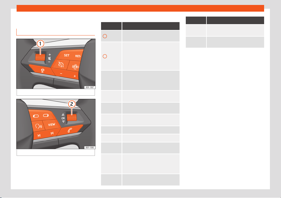
Multifunction steering wheel
Multifunction steering wheel
Functions
Fig. 1
Controls on the steering wheel.
Fig. 2
Controls on the steering wheel.
The steering wheel includes multifunction
modul
es fr
om where it is possible to control
the audio, telephone, navigation, voice con-
trol and assist functions without the driver
needing to be distracted from the road.
Buttons available depending on the version
Symbol Function
1
Turn: Turn volume up/down
Pr
ess: Mute volume
2
Turn: Search in the instrument panel
menu. In Navigation mode, turn to in-
crease/decrease map size in SEAT
Digital Cockpit
Press: Select the highlighted option in
the instrument panel
Radio: Search for the previous/next
st
ation.
Media: Short press: previous/next
track; long press: fast forward/rewind
Activate phone menu (answer call,
end call)
Switch between media and radio
sources
Change the instrument panel menu
(previous/next)
Enable/disable voice control
Change digital panel views
Connect/disconnect the Cruise con-
trol system / ACC / Speed limiter
: Activate ACC / Cruise control sys-
tem / Limiter
: Reset programmed ACC speed or
cruise control system
: Increase programmed speed
: Decr
ease programmed speed
Symbol Function
Open the drive assist menu in the in-
strument panel
Modify the programmed ACC dis-
tance
1

Seats
Seats
Adjusting the backr
est of the fr
ont
passenger seat
Fig. 3
Front passenger seat: adjusting the seat
backr
est
●
Move the lever in the direction of the arrow
›
›
›
Fig. 3, and adjust the backrest to the de-
sired position.
WARNING
Serious injuries can be caused if the pas-
senger seat backrest is l
owered or lifted
without due care and attention.
Folding table*
Fig. 4
Front left seat: folding table.
Fig. 5
Front left seat: folding table with drinks
hol
der
.
Depending on the model version, at the rear
of the fr
ont seats, ther
e may be “plane-style”
folding tables for passengers in the rear
seats.
Opening the folding table
●
Pull the table up, in the direction of the ar-
row, until it catches
›››
Fig. 4.
Folding the table or adjusting its inclina-
tion
The foldable table can be used at different
inclinations.
●
Press the unlocking lever under the table
›››
Fig. 5
1
and keep it that way.
●
Adjust: Adjust the inclination of the t
abl
e by
pressing the lever.
●
Fold: Push the table downwards while
pressing the lever.
Drink holder
A drink holder is built into the folding table
2
.
With the f
ol
dable table extended, remove the
drink holder
2
following the direction of the
arr
o
w. To store the drink holder, insert it into
the table against the direction of the arrow.
WARNING
The table must always be closed while
driving to decr
ease the risk of injuries.
2
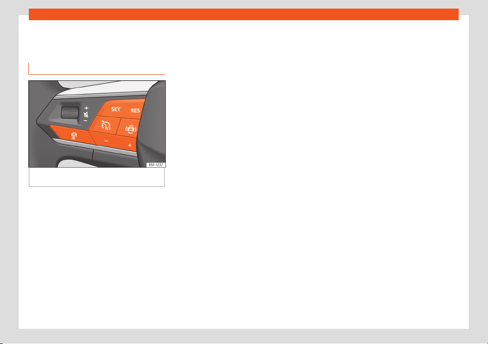
ACC - Adaptive Cruise Control*
ACC - Adaptive Cruise Con-
tr
ol*
ACC oper
ation
Fig. 6 On the multifunction steering wheel:
butt
ons t
o operate the ACC
When the ACC is connected, the green con-
tr
ol l
amp will light up on the instrument
cluster, and the programmed speed and
ACC status will be displayed on the screen.
What ACC settings are possible?
●
Connecting and activating the ACC
›››
page 3.
●
Setting your speed
›››
page 3.
●
Setting your distance
›››
page 3.
●
Disconnecting and deactivating the ACC
›››
page 3.
●
Adjusting the default distance level at the
start of your journey
›››
page 4.
●
Adjusting the driving profile
›››
page 4.
Connecting and activating the ACC
To connect and activate the ACC, the posi-
tion of the gear lever and the vehicle speed
must all be taken into account.
●
With manual transmission, the gear lever
must be in any gear except first. The speed
must be greater than 30 km/h (18 mph) ap-
prox. With automatic transmission, the gear
lever must be in position D or S. It can be acti-
vated from 0 km/h (0 mph) but the system is
automatically programmed at a speed of 30
km/h (18 mph). Attention, the vehicle may
suddenly accelerate!
●
To activate the ACC press the
›››
Fig. 6
button on the multifunction steering wheel. At
this time, the ACC is not active and there is no
programmed speed.
●
Then press button
›››
Fig. 6. At this mo-
ment the ACC is activated and the current
speed and distance are programmed. The
picture on the instrument cluster will change
to Active mode.
While ACC is active, the vehicle travels at a
set speed and distance from the vehicle
ahead. Both speed and distance can be
changed at any time.
Setting speed
●
To program the speed, press the or but-
tons to the desired speed. The speed adjust-
ment is made at 10 km/h (5 mph) intervals.
●
If you wish to increase speed by intervals of
1 km/h (1 mph), press the button or to de-
crease it press button .
The set speed can be changed when the ve-
hicle is stopped or during driving.
Setting your distance level
●
To increase or decrease the distance level
press the button .
The instrument cluster screen displays the
selected distance level. There are 5 distance
levels to choose from. SEAT recommends lev-
el 3. The set distance can be changed when
the vehicle is stopped or while driving.
Disconnecting and deactivating the ACC
●
To disconnect the ACC, press the button .
An ACC deactivated message appears and
the function is totally deactivated.
If you do not wish to disconnect the ACC, just
to switch it temporarily to inactive mode
(Standby), disconnect it by pressing the but-
ton and reconnect it or step on the brake
pedal.
»
3

Adjusting the default distance level at the start of your journey
It will also switch to inactive mode (Standby)
if the v
ehicl
e is stopped and the driver door is
opened.
Adjusting the default distance level at the
start of your journey
In wet road conditions, you should always set
a larger distance with regard to the vehicle in
front than when driving in dry conditions.
In the Infotainment system, you can pre-se-
lect the distance level when connecting the
ACC from: Very close, Close, Medium, Far
and Very far using the function button >
Driver assistance > ACC.
Changing the driving profile
In vehicles with SEAT Drive Profile, the driving
profile selected can have an influence on the
ACC’s acceleration and braking behaviour.
In vehicles without SEAT Drive Profile, the be-
haviour of the ACC can also be affected if
any of the following drive profiles are selec-
ted in the Infotainment system:
●
Normal
●
Sport
●
Eco
●
Convenience
In this case, you should access the ACC set-
tings using the function button > Driver as-
sistance > ACC.
4

SEAT S.A. is permanently concerned about continuous development of its types and models. For this reason we ask you to understand,
that at any given time, changes regarding shape, equipment and technique may take place on the car delivered. For this reason no right
at all may derive based on the data, drawings and descriptions in this current handbook.
All texts, illustrations and standards in this handbook are based on the status of information at the time of printing. Except for error or
omission, the information included in the current handbook is valid as of the date of closing print.
Re-printing, copying or translating, whether total or partial is not allowed unless SEAT allows it in written form.
SEAT reserves all rights in accordance with the “Copyright” Act.
All rights on changes are reserved.
❀
This paper has been manufactured using bleached non-chlorine cellulose.
© SEAT S.A.
5FJ012720FB
Inglés 5FJ012720FB (02.20)