Loading ...
Loading ...
Loading ...
30
CLP-625 Owner’s Manual
Keyboard Stand Assembly
CAUTION
• Assemble the unit on a hard and flat floor with ample space.
• Be careful not to confuse parts, and be sure to install all
parts in the correct orientation. Please assemble the unit in
accordance with the sequence given below.
• Assembly should be carried out by at least two persons.
• Be sure to use only the included screws of the specified
sizes. Do not use any other screws. Use of incorrect screws
can cause damage or malfunction of the product.
• Be sure to tighten all screws upon completing assembly of
the unit.
• To disassemble the unit, reverse the assembly sequence
given below.
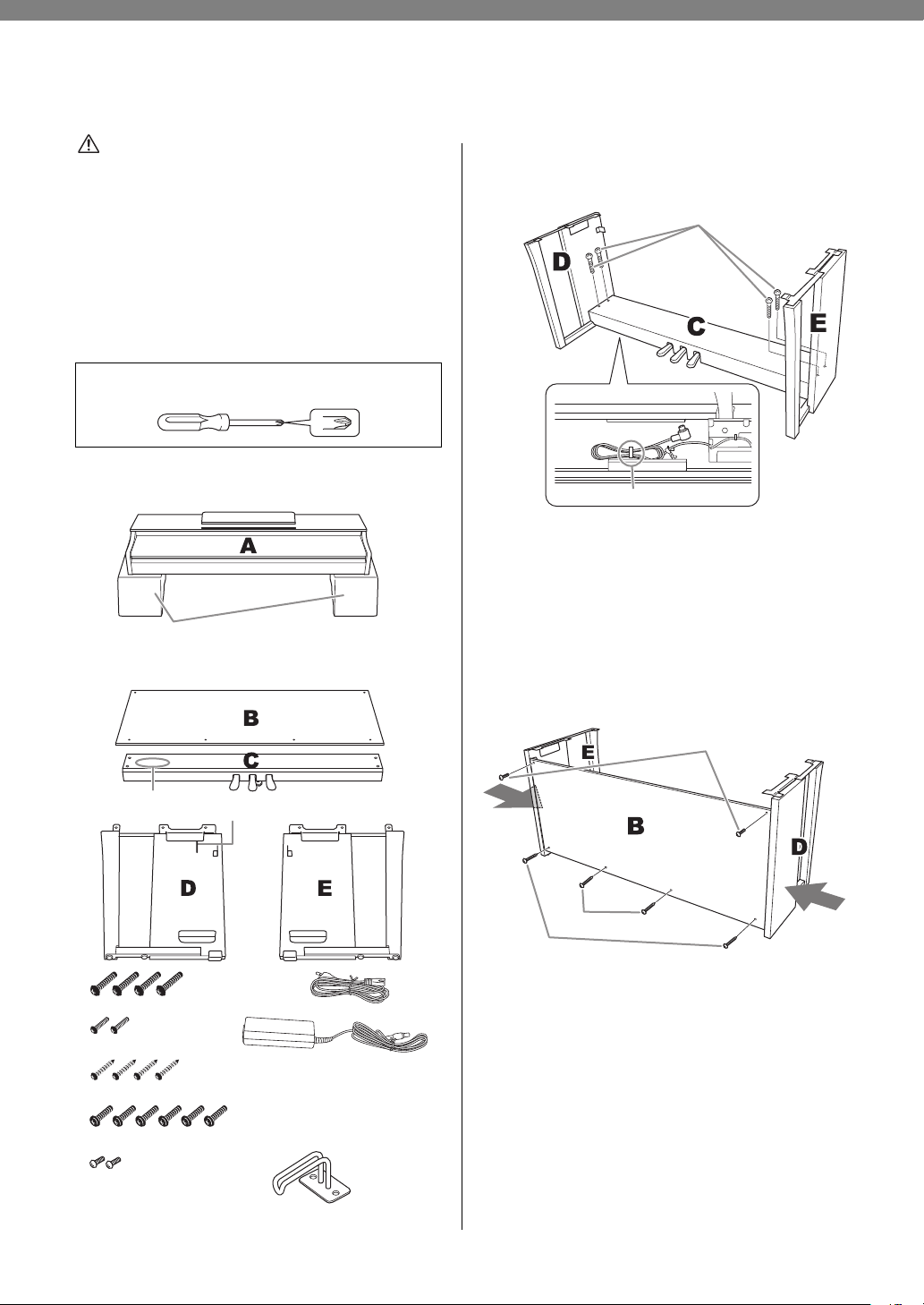
Remove all parts from the package and make sure you
have all of the items.
1. Attach (finger-tighten) C to D and
E.
1-1 Untie and straighten out the bundled pedal
cord.
1-2 Align D and E with each end of C.
1-3 Attach D and E to C by finger-tightening
the long screws (6 x 20 mm).
2. Attach B.
2-1 Align the screw holes on the upper side of B
with the bracket holes on D and E, then
attach the upper corners of B to D and E by
finger-tightening two thin screws (4 x 12
mm).
2-2 While pushing the lower part of D and E
from outside, secure the bottom ends of B
using two tapping screws (4 x 20 mm).
Have a Phillips-head (+) screwdriver of the appropriate size
ready.
Foamed styrol pads
Remove foamed styrol pads from the package, position them on
the floor, then place A on top of them. Position the pads so that
they will not hide the connectors on the bottom of A.
Bundled pedal
cord inside
6 x 20 mm long screws x 4
4 x 12 mm thin screws x 2
4 x 20 mm tapping screws x 4
6 x 16 mm short screws x 6
Power cord x 1
AC adaptor x 1
The power cord and adaptor
may not be included, or may
look different from the illustration
above, depending on your
particular area. Please check
with your Yamaha dealer.
4 × 10 mm thin screws x 2
Cord holder
Headphone hanger x 1
1-1
1-3
2-1
2-2
2-2
2-3
2-2
Loading ...
Loading ...
Loading ...