
Dear Owner,
we would like to thank you f or your
purchase of a Porsche Sports car.
Judging b y t he car you hav e chosen ,
you are a motorist of a special breed,
and you are probably no novice when it
comes to automobiles.
Remember however, as with any vehicle,
you should take time to fam iliarize
yourself with your Porsche and its
performa nce characteristics. Alway s
drive within your o wn unique capabilities
as a driver and your level of experienc e
with your Porsche. E nsure that anyone
else driving your Porsche does t he
same. To prevent or minimize injury,
always use your safety belts. Never
consume alcohol or drugs before or
during the operat ion of your vehi cle.
This Owner’s Man ual contain s a h ost
of useful inf ormation. Please take the
time to read this manu al before you driv e
your new Porsche. Become familiar with
the operation of your Porsche car for
maximum safety and operating pleasure.
The better you know y our Porsche,
the more pleasure you will experience
driving your new car. Always keep your
Owner’s Manual in th e car, and give it
to the new owner if you ever sell your
Porsche.
A separate Maintenance Booklet
explains how you can keep your P orsche
in top driving condition by having
it serviced regularly. A separate
Warranty and Customer Inform ation
Book let contains detailed inform ation
about the warrant ies cover ing your
Porsche.
For U.S. only:
If you believe that your ve hicle has a fault
which could cause a crash, injur y o r
death, you should immediately inform
the National High way Tra ffic Safety
Administrat ion (NHTSA) in addition to
notifying Porsc he Cars North America,
Inc. (Porsche Cars N.A.).
If NHTSA receive s similar c omplaints,
it may open an investigation , and if it
finds that a safety problem ex ists in a
group of vehicles, it may order a recall
and remedy campaign . However, NHTSA
cannot become involved in individual
problems between you and your dealer,
or Porsche Cars N.A..
To contact NHTSA, you may ei ther
call the Au to Safety Hotline toll-free at
1(800)424-9393 (or366-0123 i n Wash-
ington, D.C. area) or write to: NHTSA,
U.S. Department of Transportation,
Washington, D.C. 20590. You can also
obtain other information about motor
vehicl e safety from the Hotli ne.
Your car has thousands of parts and
comp onents which have been designed
and manufactured in accordance with
Porsche’s high standards of engineering
quality and safety.
Any alteration of the vehicle may
negate or interfere with those
safety features buil t in to the vehicle.
Modications may be carried out
on your vehicle only if approved by
Porsche.
1
Downloaded from www.ManualsFile.com manuals search engine

Your Porsche is int ended to be used in
a safe manner obeying the local laws
and in the light of driving conditions
faced by you, and in acco rdanc e with
the instr uctions provided in this Owner’s
Manual.
Do not misuse your Porsche by
ignoring those laws and dri ving con-
ditions , or by ignoring the ins truc-
tions in this manual. Any alteration
or misuse of the vehicle can lead to
accidents and severe or fatal person
al injuries.
The fitting of racing tires (e.g. slicks)
for sporting events is not ap proved by
Porsc he. Very high cornering speeds
can be achieved with racing tires.
However, the resulting transv erse
acceleration values would jeopardize
the adequate supply o f oil to the engine.
Porsche therefore will not accept
any warranty or accept any liabil ity
for damage occurring as a result of
non-compliance with this provision.
Regularly check your vehicle for
signs of d amage. Dama ged or
missing aerodynamic components
such as spoilers or underside pan-
els affect the driving behavior and
therefore mus t be replaced immedi-
ately.
Your car may have all or some of the
components described in this manual.
Should you have difficulty understanding
any of the explanations of features or
equipment inst alled in your vehicle,
contact your authorized Porsche dealer.
He/Sh e will be glad to assist you. Also
check w ith your dealer on other available
options or equipment.
Throughout this booklet, left is desig nat-
ed as the driver’s side of the vehicle, and
right as the passe nger’s side of the vehi-
cle.
Text, illustrations and specifications in
this man ual are based on the information
available at the time of printing .
It has always been Porsche’s policy
to continuously improve its products.
Porsche , therefore, reserve s the
right to make changes in design and
specification, an d to make additions
or improvements in its product without
incurr ing any obligation to ins tall them on
products previously manufactured.
We wish you many miles of safe and
pleasurable driving in your Porsche.
Warning!
For your own protection and longer
service life of your car, pleas e
follow all operatin g instr uctions and
special warnings. These special
warnings use the safety alert symbol,
followe d by the words Danger,
Warning and Caution. Th ese
special warnings contain important
mess ages regarding your safety
and/o r the potential for dama ge
to your Por sche. Ignoring the m
could result in serious mechanical
failure,ser ious personal injury or
death.
Do not alter your Porsche. Any alter-
ation could create dangerous con-
dition s o r defeat safety engineering
features built in to your car.
2
Downloaded from www.ManualsFile.com manuals search engine

Do not misuse your Porsche. Use it
safely, and consistent ly with the law,
acco rding to the driving conditions,
and the instructio ns in this manual.
Alteration or misuse of your Porsche
could cause accidents a nd severe or
fatal personal inj uries.
3
Downloaded from www.ManualsFile.com manuals search engine

Imprint
WKD 987 621 07
4/06
© Dr. Ing. h.c. F. Porsche AG
Porsche , the Porsche crest, PCCB, Tiptronic and
Tequipm ent are registered trademark s and the
distinctive shapes of Porsche automobi les are
tradem arks of
Dr. Ing. h.c. F. Porsche AG.
All rights reserved.
Printed in Germany
32654
Note to owners
In Canada, this manual is also available in French.
To obtain a copy contact your dealer or write to:
Note aux proprietaires
Au Canada, ce manuel est également disponible
en francais. Pour en obtenir un exemplaire,
adressez-vous à votre concessionnaire ou écri vez
à l’adresse ci-dessous.
Porsche Cars Canada, Ltd.
Automobiles Porsche Canada, LTEE
5045 Orbitor Drive
Building #8, Suite 200
Mississauga, Ontario
Canada L4W 4Y4
Telephone number for customer ass istance:
1-800-PORSCHE / Option 3
4
Downloaded from www.ManualsFile.com manuals search engine

Fuel Quality
Your engine is designed to provide o ptimum performanc e and fuel economy using unleaded premium fuel with an octane rating of 98 RON
(93 CLC or AKI). Porsch e therefore recommends the use of these fuels in you r vehicle.
Porsche also recognizes that these fuels may not always be available. Be assured that your vehicle will operate properly on unleaded premium fuels with octane
numbers of at least 95 RON (90 CLC or AKI), since the engine’s “Electronic Octane™ knock control” will adapt the ignition timing, if necessary.
Fuels containing alcohol and e ther
Some areas of the U.S. require oxygenated fuels during certain portions of the year. Oxygenated fuels are fuels which contain alcohols (such as methanol or etha-
nol) or ether (such as MTBE).
Under normal conditions, the amount of these compounds i n the fuel will not affect driveab ility.
You may use oxygenated fuels in your Porsche, provided the octane requirements for your vehicle are met. We recommend, however, that you change to a differ-
ent fuel or s tation if any of the following problems occur with your vehicle:
– Deterioration of driveability and performance.
– Substan tially reduced fuel economy.
– Vapor lo ck and non-start problems , especially at high altitude or at high temperature.
– Engine malfu nction or stalling.
Fuels containing MMT
Some North American fuels contain an octane enhanci ng additive called methylcy clopentadienyl manganese tricarbonyl (MMT). If such fuels are used , your emis -
sion control system performance may be negatively affected. The check engine warning lights on your instrument panel may turn on. If this occurs, Porsche
recommends you stop using fuels containing MM T.
5
Downloaded from www.ManualsFile.com manuals search engine

Porsche and the Environment
Environmental gu idelines
We develop and produce exclusive vehicles with
advanced environmental and safety technology
and a great ability to fascinate.
Our envir onmental pol icy is based on the
following principles:
– The maximum possible use of en v ironmental
and safety technology that is economically
justifiable.
– Economical usage of en ergy and resources.
– Involvement of our business partners and
contrac tors in ou r efforts to protect the
environment.
– Open dialogue with all social groups.
California Propositi on 65 Warning
Warning!
Engine exhaust, some of its constituents, and
certain vehicle components contain or emit
chemicals known to the State of California
to cause cancer and birth defects or ot her
reproductive harm. In addition, certain fluids
contained in vehicles and certain products of
component wear contain or emit chemicals
known to the State of California to cause
cancer and birth defects or other reproductive
harm.
Prod uction
Whethe r in production or repair, Porsche always
relies on en v ironmentally friendly technology. An
example of this is the water-based paint used in our
painting installations. Water-base paints and new
painting methods reduc e solvent emissions by 70
per cent. The water used i n the painting installation
is recirculated. Waste water leaves the Porsche
factory only after being appropriately treated.
A waste-management system has been introduced
to reduc e the amount of waste while simultaneous-
ly increasing the recycling rate.
Environmentally friendly vehicles
Modern environmental technology ensures
complia nce with all emission laws applicable
worldwide.
It has the following advantages:
– Rapid operational readiness of the catalytic
converters ensures low emissions, even in
short-trip operation.
– Reliable operation and good emission control
over a long useful life.
Please observe the chapter ”FUEL ECONOMY”
on page 214.
6
Downloaded from www.ManualsFile.com manuals search engine

Recycl ing - f or a Porsche, this is virtually
an academic question
More than two-thirds of all Porsches ever built are
still running.
Just in case recycling is ever necessary, we
take the following precautionary measures:
– Identification of all materials.
– Use of recyclable materials.
– Reusable components designed for simple
removal.
– These reasons result in a further increase in
the recycling rate which is cu rrently 80 per
cent.
Emission control is built in
Innovative engine technology combines high
engine performance and environmental compatibil-
ity.
The engine diagnosis system electronically
monitors the components and systems that affect
exhaus t gases .
This continuous monitoring and fault storage ena-
bles swift, reliable diagnosis and fault detection.
Any fault messages are indicated to the driver by
the “Check Engine” warn i ng light and the on-board
computer.
Please observe the chapter ”WARNIN GS
ON THE INSTRUMENT PANEL AND THE
ON-BOARD COMPUT ER” on page 138.
7
Downloaded from www.ManualsFile.com manuals search engine

General safety instructions
Porsche Ceramic Composite Brake
(PCCB )
Please observe the chapter ”BRAKES” on page
66.
The high-performance brake system is designed
for optimal braking effect at all speeds and
temperatures. Certain speeds, braking forces
and ambient condition s (such as te mperature and
humidity) therefore might cause brake noises.
Wear on the diffrent components and braking
system, such as brake pads and brake discs,
depends to a great extent on the individual driving
style and the conditions of use and therefore
cannot be expressed in actual miles on the road.
The values communicated by Porsche are based
on normal operation adapted to traffic. Wear
increases considerab ly when the vehicle is driven
on race tracks or through an aggressive driving
style.
Please consult an au thorized Porsche dealer
about the current guidelines in effect before
such use of your vehicle.
Setting and oper ation vehicle components
when driving
Warning!
There is a danger of an accident if you oper-
ate or set the on-board compute r, radio, navi-
gation syste m, telephone or other equipment
when drivin g. This could distract you from
the trafc and cause you to lose control of the
vehicle result i ng in serious personal injury or
death.
Operate the equipment while driving only if th e
traffi c situation allows you to do so safely.
Carry out any complicated operating or setting
procedures only with the vehicle stationary.
Portable Fuel Containers
Danger!
Portable fuel containers may leak, whether
they are full or part i ally empty. Fuel leaking
from a portable container carried in your
vehicle could, in case of an acc ident, cause a
re or explosion, resulting in serious perso nal
injury or death.
Never carry additional fuel in portable contain-
ers in your v ehicle.
8
Downloaded from www.ManualsFile.com manuals search engine

Engine Exhaust
Danger!
Engine exhaust is dangerous if inhaled.
Engine exhaust fumes have many compo-
nents which you can smell. They also contain
carbon monoxide (CO), which is a colorless
and odorless gas. Carbo n mon oxide can
cause unconsciousness and even death if
inhaled.
Never start or let th e engine run i n an
enclosed, unventilate d area. It is not rec-
ommended to sit in your car for prolonged
periods with the engine on and the car not
moving.
Ground Clearance
Caution!
Risk of damage. The vehicle may touch
the ground as a result of reduced ground
clearance.
Drive carefully and slowly on steep slopes
(e.g. parking lots, curbs, uneven roads, lifting
platfor ms, etc.).
Avoid steep ramps.
9
Downloaded from www.ManualsFile.com manuals search engine


Controls , Instruments
Dear Porsche Owner ...................................... 15
Before driving off... ........................................ 16
In the driver’s seat... ...................................... 17
On the road... ................................................ 18
Break in hints for the first 2000 miles/300 0
kilometers .................................................... 19
Never invite car theft! ..................................... 21
Keys ............................................................ 22
Key with Radio Remote Control ....................... 23
Central Locking in Cars without Alarm System .. 25
Central Locking in Cars with Alarm System . . ..... 28
Doors .......................................................... 31
Alarm System, Passenger Compartment Monitor-
ing .......................................... ..................... 32
Power Windows ............................................ 34
Mirrors .... ..................................... ................ 36
Seat Adjustment ............................................ 40
Seat Memory ................................................ 43
Heated Seats ................................................ 4 5
Steering Wheel Adjustment .................. . . ......... 46
Multi-functional steering wheel ........................ 47
Sun Visors .................................................... 48
Safety Belts ....... ........................................... 49
Airbag Systems ...................................... ...... 52
Child Restraint Systems ................................. 58
LATCH System .............................................. 62
Child Restraint Anchorage .............................. 63
Clutch Pedal ................................................. 64
Parking Brake ............................................... 65
Brakes ....................................... .................. 66
ABS Brake System ........ ............ .................... 69
Sports Exhaust System .................................. 71
Sport Mode ............................ ............ .......... 72
Porsche Stab ility Management (PSM) ............... 73
Porsch e Active Suspension Management
(PASM) ................................ ......................... 76
Retractable Rear Spoiler .............................. .. 77
Parking Aids ................................................. 79
Interior Lights ........................... .................... 81
Operation, Instruments .................................. 82
Ignition/Starter Switch with anti-theft Steering
Lock ........................................... ................. 83
Starting and Stopping Engine .......................... 86
Instrument Panel USA Models ................ ......... 88
Instrument Panel Canada Models .................... 90
Autom atic Speed Control In dicator Light .......... 92
Instrument Illumination ................................... 93
Trip Odometer ......................................... ..... 94
Speedometer ............................................... 95
Tachom eter ....................... ............ ............. .. 96
Turn Signal Indicator Light ............................ .. 96
Cooling system ............................................. 97
Tiptronic S .................................................... 98
Fuel ............................................................. 99
Clock ......................................................... 100
Battery ................. ...................................... 101
Check Engine Warning Light ......................... 102
Central Warning Light ................................... 103
Brake Warning Light ..................................... 104
On-Board Computer (BC) .............................. 105
LIMIT Acoustic warning signal for speed limit .. 108
INFO Warning messages .............................. 111
TEL Telephone informa ti on ..... ...................... 112
CHRONO Sto p watch .................................... 115
TPC Tire Pressure Monitoring . ...................... 122
OIL Display and measurement of the engine oil
level ........................................................... 131
SET Basic setting on on-board computer ........ 134
General inform ation regarding the on-boa rd
compu ter func tions ............... ...................... 137
Warnings on the instrument panel and the on-board
compu ter ...... ............. ................................ 138
Light Switch . ............................................... 147
Welcome Home Lighting .............................. 147
Autom atic Headlight Beam Adjustment .......... 148
Turn Signal/ Headligh t Dimm er/Parking light /
Flasher Lever ................ ............. ................. 149
Windshield Wiper / Washer Lever .................. 150
Autom atic Speed Control ........................ ..... 153
Air conditioning ........................................... 156
Autom atic air conditioning system .... ............. 159
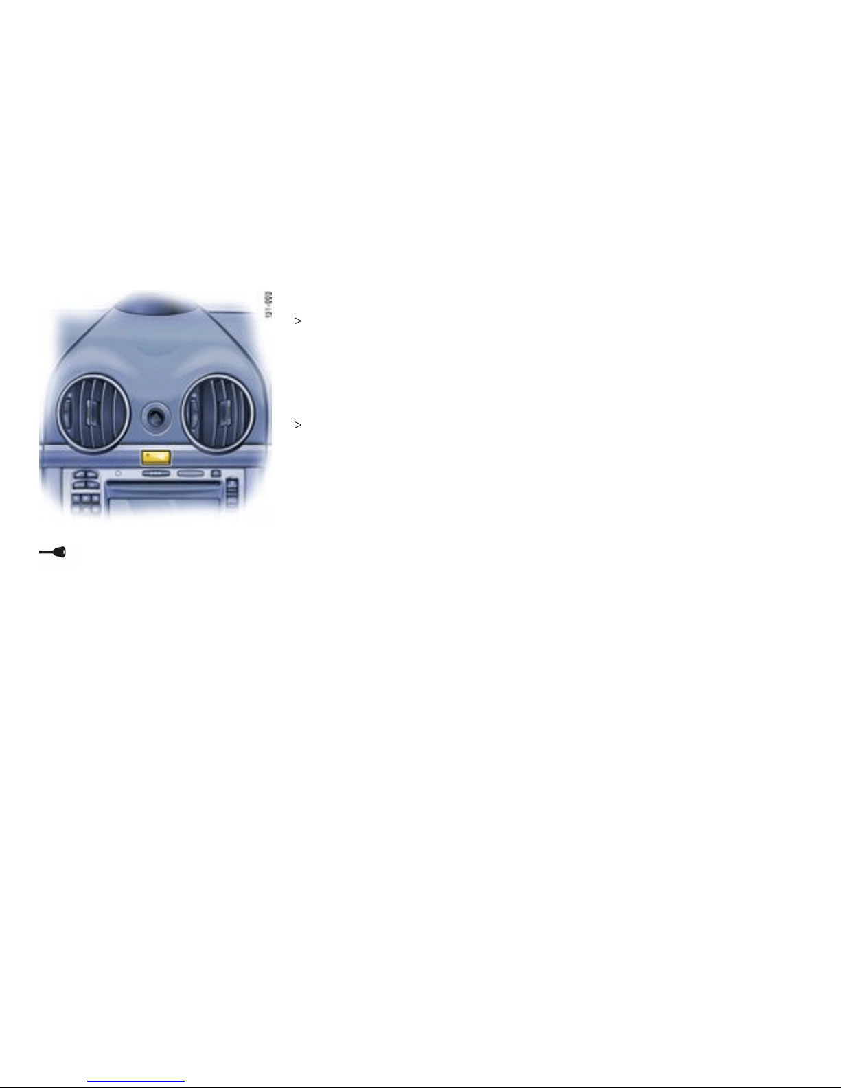
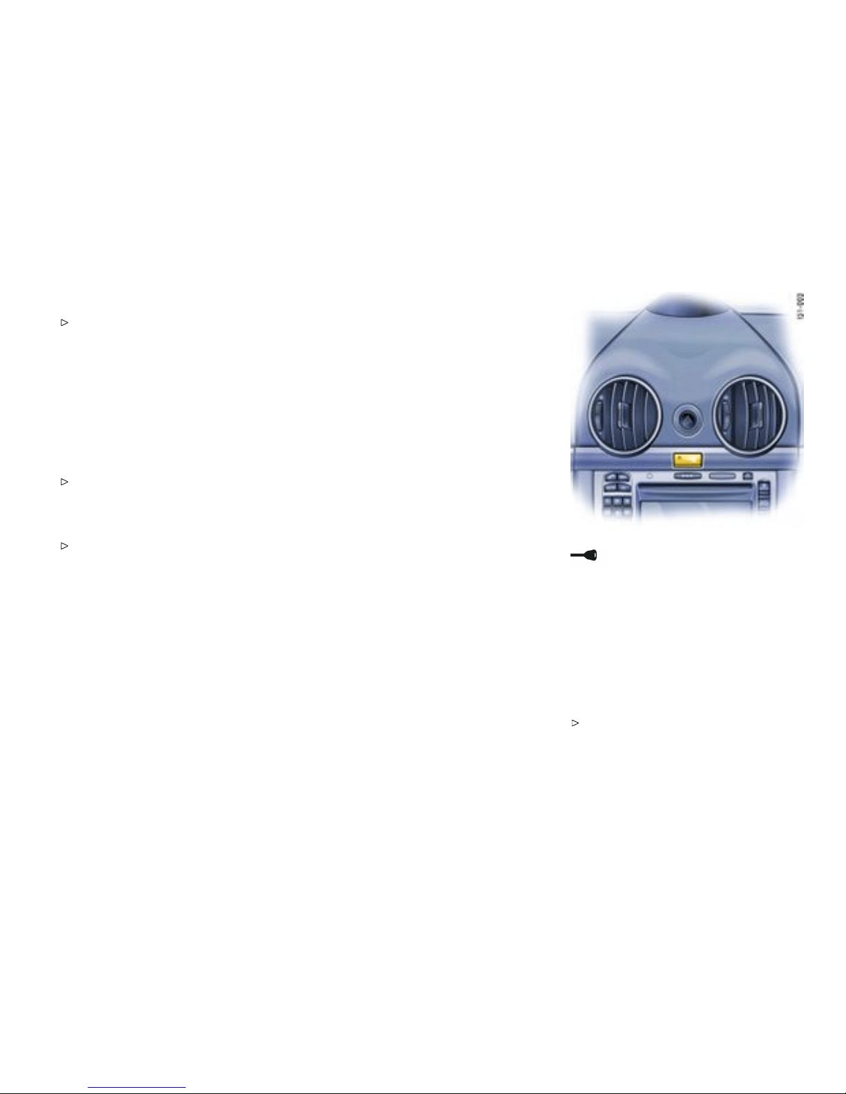
Central and side vents .................................. 162
Fresh-air intake .......................... ................. 162
Emergency Flasher Switch ........................... 163
Ashtray ...................................................... 164
Cigarette Lighter ......................................... 165
Sockets ..................................................... 166
Storage in the passenge r compartment ......... 167
Cupholder ........ ............ ............. ............ ..... 170
Fire extinguisher .......................................... 172
Controls, Instrume nts
13
Downloaded from www.ManualsFile.com manuals search engine

Trunk Entrapment ........................................ 173
Front Luggage Compartment lid .................... 174
Front Luggage Compartment ....................... . 176
Rear Lid ............................................... ...... 178
Rear luggage compartment ......................... . 179
Porsche Communication Management (PCM) . 184
Car Audio Operation/Tips ............................. 185
HomeLin k ................................................... 188
Roof Tra n s port System . .. ...................... ....... 191
14Controls, Instruments
Downloaded from www.ManualsFile.com manuals search engine

Dear Porsche Owner
A lot has gone into the manufacture of your
Porsche, i ncluding advan ced engineering, rigid
quality control and demanding inspecti ons. These
engineering and safety features wil l be enhanced
by you...
the safe driver...
– who knows her/his car and all controls,
– who maintains the vehicle properly,
– who uses driving skills wisely, and always
drives within her/his own capabilities and the
level of familiarity with the vehicle.
You will find helpful hints in this manual on how to
perform most of the checks listed on the following
pages. If in doubt, have these checks performed
by your authorized Porsc he dealer.
Controls, Instrume nts
15
Downloaded from www.ManualsFile.com manuals search engine

Before driving off...
Check the following items rst
Turn the engine off before you attempt any
checks or repairs on the vehic le.
Be sure the tires are inflated correctly. Check
tires for dam age and tire wear.
See that wheel bolts are properly tightened
and not loose or missing.
Check engine oil level, add if necessary. Make
it a habit to have engine oil checked with every
refueling.
Check all fluid levels such as windshield
washer and brake fluid levels.
Be sure the vehicl e batt e ry is well charged and
cranks the engine properly.
Check all doors and lids for proper operati on
and latch them properly.
Check and if necessary replace worn or
cracked wiper blad es.
See that all windows are clear and unobstruct-
ed.
Check air intake slots and area between front
lid and windshiel d. Ensure that these areas
are free of snow and ice, so the heater and the
windshie ld wipers work properly.
If a ch ild will be riding in the vehicle, check child
seat/child seat restraint system to ensure that
restraints are properly adjus t ed.
Check all exterior and interior lights for
operation and that the lenses are clean.
Check the headlights for proper aim, and i f
necessary, have them adjusted.
Check under the vehicle for leaks.
Be sure all luggage is stowed securely.
Emergency equipment
It is good practice to carry emergency equipment
in your vehicle. Some of the items you should have
are: window scraper, snow brush, container or
bag of sand or sa lt, emergency light, small shovel,
first-aid kit, etc.
16Controls, Instruments
Downloaded from www.ManualsFile.com manuals search engine

In the driver’s seat...
Check operation of the horn.
Position seat for easy reach of foot pedals
and controls. To reduce the possibility of
injury from the a irbag deployment, you should
always sit back as far from the steering wheel
as is practical, while still maintaining full
vehicle control.
Adjust the inside and outside rear view mirrors.
Buckle your safety belts.
Check operation of the foot and parking brake.
Check all warning and indicator lights with
ignition on and engine not running.
Start engine and check all warning displays for
warning symbols.
Never leave an idling car unattended.
Lock doors from in side, especially with
children in the car to prevent inadvertent
openin g of doors from inside or outside. Dr ive
with doors locked.
Controls, Instrume nts
17
Downloaded from www.ManualsFile.com manuals search engine
On the road...
Never drive after you have consumed alcohol
or drugs.
Always have your safety belt fastened.
Always drive defensively. Expect the un expect-
ed.
Use signals to indicate turns and lane changes.
Turn on headlights at dusk or when the driving
conditio ns warrant it.
Always keep a safe distance from the vehicle
in front of you, depending on traffi c, road and
weather conditions.
Reduce speed at night and during inclement
weather. Driving in wet w eather requires
caution and reduced speeds, particularly
on roads with standing water, as the handlin g
charac teristics of the vehicle may be impaired
due to hydroplaning of the tires.
Always observe speed limits and obey road
signs and traffic laws.
When tired, get well off the road, stop and take
a rest. Turn the engine off. Do not sit in the
vehicle with engine idling.
Please observe the chapter ”ENGINE
EXHAUST” on p age 9.
When parked, always set the parking brake.
Move the Tiptronic selector lever to ”P“ or the
gearshift lever to reverse or first gear. On hills
also turn the front wheels toward the curb.
When emergency repairs become necessary,
move the vehicle well off the road. Turn on
the emergency fl asher and use other warning
devices to ale rt other motorists. Do not park
or operate the vehicle in areas where the hot
exhaust system may come in contact with dry
grass, brush, spilled fuel or other flammable
material.
Make it a ha bit to have the engine oil checked
with every refueling.
Danger!
Danger of re in engine compartment due
to burning cigars or cigarettes. Serious
personal injury or d eath could result from
re i n the engine compartment.
Do not throw any lit cigars or cigarettes out
of the vehicle. They can be blown into the air
inlets by the air flow and cause a fire in the
engine compartment.
Please obser ve the chapter ”ASHTRAY” on
page 164.
18Controls, Instruments
Downloaded from www.ManualsFile.com manuals search engine

Break in hints for the rst 2000
miles/3000 kilome ters
The following tips will be helpful in obtaining
optimum performance from your new Porsche.
Despite the most modern, high-precision manufac-
turing methods, the m oving parts must still wear
in with each other. This wearing-in occurs mainly in
the first 2000 miles/3000 kilometers.
Therefore:
Preferably take longer trips.
Avoid frequent cold starts with short-distance
driving when ever possible.
Avoid full throttle starts and abrupt stops.
Do not exceed maximum engine speed of
4200 rpm (revolutions per minute).
Do not run a cold engine at high rpm either in
Neutral or in gear.
Do not let th e engine labor, especially when
driving uphill. Shift to the next lower gear in
time (use the most favorable rpm range).
Never lug the engine in h igh gear at low
speeds. This rule applies at all ti mes, not just
during the break-in period.
Do not participate in motor racing events,
sports driving schools, etc. during the first
2000 miles/3000 kilometer s.
There may be a slight stif fness in the steering,
gear-shifting or other controls during the break-in
period which will gradually disappear.
Break in brake pads and break discs
New brake pads and discs have to be “broken in”,
and therefore only attain optimal friction when
the car has covered several hundred miles or
km. The slightly reduced braking ability must be
compensated for by pressin g the brake pedal
harder. This also applies whenever the brake pads
and brake discs are replaced .
New tires
New tires d o not have maximu m traction. They
tend to be slippery.
Break in new tires by driving at moderate
speeds during the first 60 to 120 miles/100
to 200 km. Longer braking distances must be
anticipated.
Engine oil and fuel consumption
During the break-in period oil and fuel consumption
may be higher than normal.
As always, the rate of oil consumption depends
on the quality and viscosity of oil, the speed at
which the engine is operated, the climate and road
conditions, as well as the amount of dilution and
oxidation of the lubricant.
Make a habit of checking engine oil with every
refueling, add if necessary.
Controls, Instrume nts
19
Downloaded from www.ManualsFile.com manuals search engine
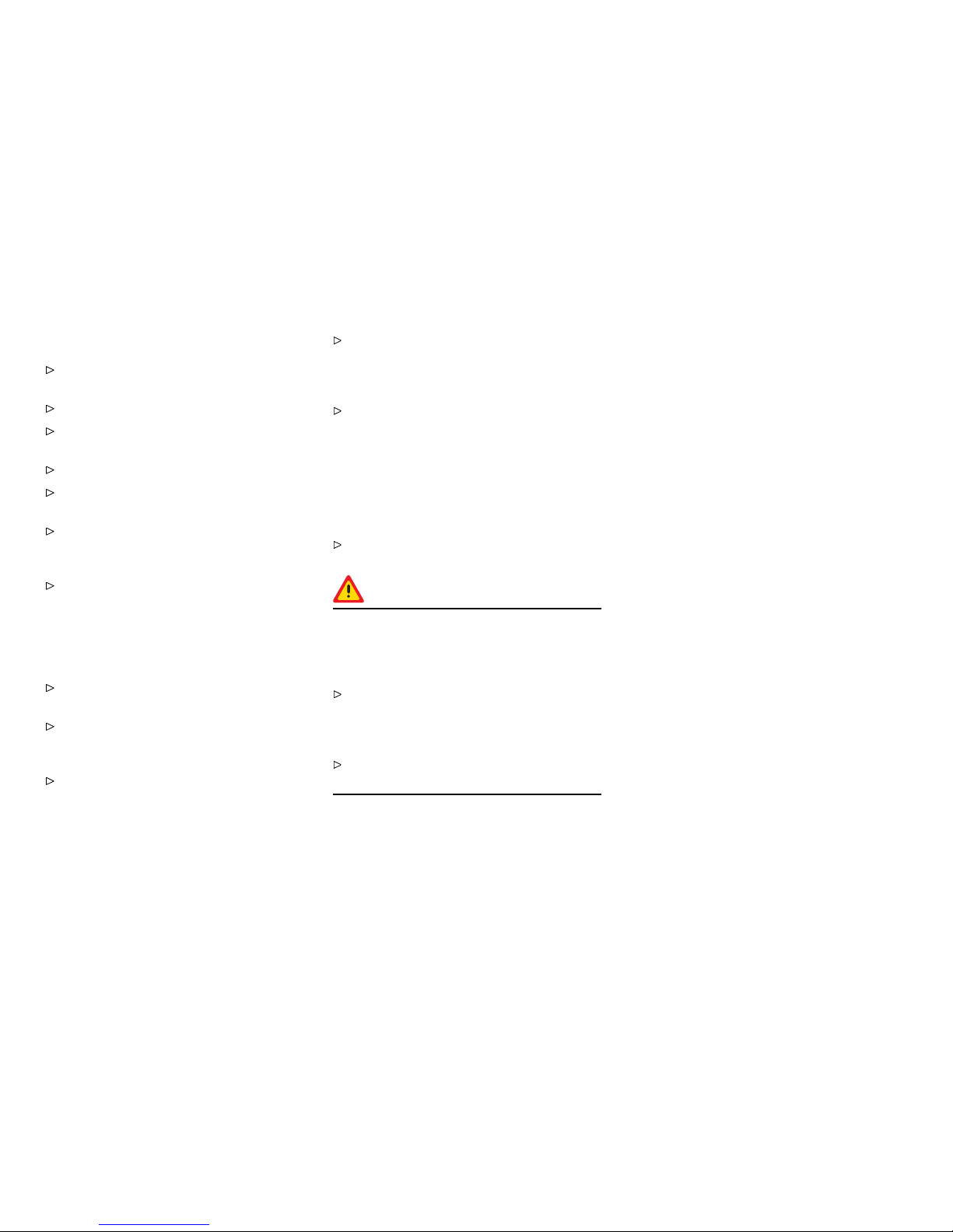
1 Inner door handle
2 Power windows
3 Door mirror control
4 Light switch
5 Ignition / starter switch
6 Turn signal / h eadlight dimme r, asher lever
7 Operating lever for on-board c omputer
8 For vehicles with Tiptronic: Toggle switches for
Tiptronic
9 Horn
10 Emergency asher switch, central locking
switch
11 Switches for rear spoiler, Porsche Activ
Suspension Managem ent (PASM), Sport mode,
Porsche Stab ility Management (PSM), Sports
exhaust system
12 Cupho lder
13 Switch for seat memory
14 Diagnostic socket
15 Switch for front luggage compartment release
16 Switch for rear li d release
17 Steering-wheel adjust ment
18 Seat adjustm ent
20Controls, Instruments
Downloaded from www.ManualsFile.com manuals search engine

Never invite car theft!
An unlocked car with the key in the ignition lock
invites car theft.
A steering wheel lock and a gong alarm are
standa rd equipment i n your Porsche. The gong
alarm will sound if yo u open the d river’s door while
the key is still in the ignition lock. I t is your reminder
to pull the key out of the ignition lock and to lock
the doors.
Warning!
Any uncontrolled movement of the vehicle
may result in property damage, serious
personal injury or death. Never leave your
vehicle unattended with the key in the ignition
lock, especially if children and/or pets are left
unattended in the vehicle. They can operate
power wind ows and other controls. If the
engine is left running, they may accidentally
engage the shift lever. Serious personal injury
or death could result from loss of c ontrol of
the vehicle.
Always remove the ignition key.
Always set the parking brake.
Lock the doors with the remote control.
Warning!
Risk of a serious accident. The steering
column will lock when you remove the key
while you are driving or as the car is rolling
to a stop. You will not be able to steer the car.
Serious personal injury or death could result
from loss of control of the vehicle.
Never remove the key from the steering lock
while you are driving.
To protect your vehicle and your
posses sions from t heft, you should always
proce ed as follows when leaving your
vehicle:
Close windows.
Lock glove compartment.
Remove ignition key.
Close storage tray betwe en the seats.
Remove valuables (e.g. car documents,
telephone, house keys) from the car.
Lock doors.
Controls, Instrume nts
21
Downloaded from www.ManualsFile.com manuals search engine

Keys
General in formation regarding the keys
Please observe the chapter ”ALARM SYSTEM,
PASSENGER COMPARTMENT MONITORING”
on page 32.
Please observe the chapter ”CENTRAL
LOCKING IN CARS WITH ALARM SYSTEM”
on page 28.
Two main keys and one spare key are supplied with
your Porsche. These keys operate all the locks on
your vehicle.
Be careful wi th your car keys: do not part with
them except under e xceptional circumstanc-
es.
To avoid battery run-down , always remove the
ignition key from the ignition lock.
Replacement keys
Order of r eplacemen t keys
Replacement car keys can be obtained only from
your authorized Porsche dealer, and this can
sometimes be very time-consuming. You should
therefore always keep the spare ke y on your
person. Keep it in a safe place (e.g. w allet), but
under no circumstances in or on the vehicle.
The key codes of new keys have to be “report ed”
to the car control unit by your authorized Porsche
dealer.
A total of 6 car keys can be reported to the control
unit.
Disabling key codes
If a key is lost, the key codes can be disabled by
an authorized Porsche dealer. All the remaining
car keys are required for this purpose. Disabling
the code ensures that the car can be started only
using authorized keys.
Note
Please note that the other locks can still be
opened with the disabled key.
Immobilizer
There is a transponder (an electronic component)
in the key grip, containing a stored code. When the
ignition is switched on, the ignition lock checks the
code. The immobilizer can be switched off and the
engine started only using an authorized ignition
key.
Switching off the immobilizer
Insert the ignition key into the ignition lock.
If the ignition is left on for more than 2 minutes
without the engine being started, the immobilize r is
switche d on again.
If this happens, turn the ignition key to the left
before starti ng the engine. The immobilizer
is switched of f again, and the engine can be
started.
Please observe the chapter ”IGN ITION/START-
ER SWITCH WITH ANTI-THEFT STEERING
LOCK” on page 83.
Switching on the immobilizer
Remove ignition key.
Security wheel bolts
If wheels have to be removed during a repair-
shop visit, do not forget to h and over the sock-
et for the security wheel bolts along with the
car key.
22Controls, Instruments
Downloaded from www.ManualsFile.com manuals search engine
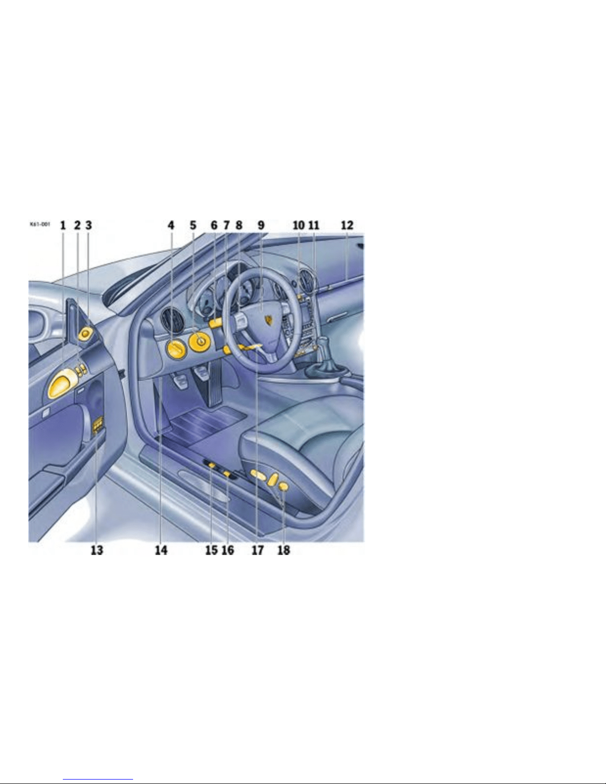
A - Main key
1 - Cent ral locking button
2 - Button for front luggage compartment lid
3 - Butt on for rear lid
4 - Ligh t-emitting diode
B - Spare ke y
Key wit h Radio Remote C ontrol
Unlocking the vehicle
Press button 1.
Locking the vehicle
Press button 1.
Switching off the alarm syste m if it is
triggered accide ntally
Press button 1.
Unlocking front lu ggage compartment
Press button 2 for approx. two seconds.
Unlocking rear lid
Press button 3 for approx. two seconds.
If the vehicle was locked before the luggage com-
partment is opened, it is unlocked simultane ously
with the luggage compartment. In vehicles with
seat memory the stored seat and door mirror posi-
tions are automatic ally set. The vehicle will be
locked again approx. 15 seconds after the lug-
gage compartment is closed if none of the doors
was opened.
Note
Your authorized Porsche dealer can program
further types of unlocking.
Type 1
The relocking time of th e doors can be adjusted to
suit your individual requirements (4 - 120 s econds).
Type 2
The doors stay locked when the luggage compart-
ments are unlocked.
Malfunction of the remote control
The remote control may not f unction correctly due
to local radio wave interference. The vehicle will
then not lock properly. This can be identified by the
missing locking sound and the missing check-back
signal of the hazard warning lights.
If this should occur:
Controls, Instrume nts
23
Downloaded from www.ManualsFile.com manuals search engine

Lock the vehicle with the key in the door.
The remote-control standby function
switches off after 7 days
If the vehicle is not started or unlocked with
the remote c ontrol within five days, the remote
control standby function is switched off (to prevent
discharging of the car battery).
1. In this case, unlock the driver’s door with the
key at the door lock. Leave the door closed in
order to prevent the alarm system from being
triggered.
2. Press button 1 on the remote control.
The remote control is now activated again and the
alarm system is switched off.
Note
Do not insert the ignition key into the ignition
lock if the vehicle battery is discharged. The
ignition key can no longer be remov ed.
The key cannot be remo ved until the vehicle
electric al system is supplied with power again.
Please observe the ch apter ”EMERGENCY
UNLOCKING OF THE FR ONT LUGGAGE
COMPARTMENT LID” on p age 260.
Please observe the ch apter ”EMERGENCY
STARTING WITH JUMPER CABLES” on page
267.
24Controls, Instruments
Downloaded from www.ManualsFile.com manuals search engine

Central Locking i n Cars w ithout
Alarm System
Gener al informati on regarding centra l
lockin g
This device complies with:
Part 15 of the FCC Rules
RSS-210 of Industry Canada.
Operation is subj ect to the following two condi-
tions:
1. This device may not cause harmful interfer-
ence, and
2. this device must accept any interference
received, including interference that may
cause undesired operation.
Note
The manufacturer is not responsible for any
radio or TV interference caused by unauthorized
modific ations to this equipmen t. Such modifi cation
could void the user’s authority to operate the
equip m ent.
Warning!
Any changes or modificat ions not expressly
approved by Porsche could void the user’s
authority to operate this equipment.
Please observe the chapter ”LOAD SWITCH-
OFF AFTER 2 HOURS OR 7 D AYS” on page
259.
Please observe the chapter ”SEAT MEMORY”
on page 43.
Both car doors and the filler flap can be centrally
unlock ed or locked with the remote control.
Any person remaining in the lo cked car can
open the door with the inner door handle:
3. Pull inner door handle once to unlock door
lock.
4. Pull inner door handle again to open door.
Automatic relocking
If the car is unlocked by remo te control and
none of the car doors is opened within approx.
60 seconds, autom atic relocking takes place. This
relocking time can be adapted to your individual
requirements (4 - 120 seconds) by an authorized
Porsche dealer.
Emergency ope ration - opening
Unlock the driver’s door with the key at the
door lock.
Emer gency operation - closi ng
Lock the driver’s door with the key at the door
lock. If there is a defect in the central locking
system, all functioning elements of the central
locking system will be locked.
The fault should be remedied immediately at an
authorized Porsche dealer.
Indication by emer gency asher
If the remote control is used for unlocking or
locking, a response is provided by the emergenc y
flasher:
– Unlock ing - single flash.
– Locking - double flash.
Overload protection
If the central locking system is operated more
than ten times within a minute, further operation is
blocke d for 30 seconds.
Controls, Instrume nts
25
Downloaded from www.ManualsFile.com manuals search engine
Central locking switch
The central locking switch on the dashboard lets
you lock and unlock both doors electrically.
Note
If the doors are locked with the key or remote
control, they can not be opened by pressing the
central locking switc h.
Locking
Press the rocker-switch. Indicator light in the
rocker switch lights up if ignition is o n. If the
doors were locked with the central locking
switch, they can be opened by pulling the inner
door handle twice.
Unlocking
Press the rocker-switch. Indicator light goes
off.
Automatic door locking
Your au thorized Porsche dea ler can program
diverse types of automatic door l ocking in the
control unit of the centr al locking system.
Type 1
Doors lock automatically when the ignition is
switched on.
Type 2
Doors lock automatic ally when a speed of 3 -
6 mph (5 - 10 km/h) is exceeded.
Type 3
Doors lock automatically when the ignition is
switched on. If doors are opened with the engine
running, they lock again automatically when a
speed of 3 - 6 mph (5 - 10 km/h) is exceeded.
Type 4
The doors do not lock automatically.
Note
Automatically locked doors can be unlocked with
the central locking button or opened by pulling on
the inside door handle twice.
On vehicles with the Sport Chrono Package Plus,
the PCM can be used to activate automatic door
locking.
26Controls, Instruments
Downloaded from www.ManualsFile.com manuals search engine

Please observe the chapter “Individual
Memory” in the separate PCM operating
instructions.
Warning!
In an emergency situation where you need to
exit the car through an automatically locked
door, remember the following procedu re to
open the door.
Unlock the doors by pressing the central
locking butto n or
pull the inside door handle twice to open the
door.
Controls, Instrume nts 27
Downloaded from www.ManualsFile.com manuals search engine

Central Locking i n Cars with Alarm
System
General information regarding central
lockin g
This device complies with:
Part 15 of the FCC Rules
RSS-210 of Industr y Cana da.
Operation is subject to the following two condi-
tions:
1. This device may not cause harmful interfer-
ence, and
2. this device must accept any interference
received, including interference that may
cause undesired operatio n.
Note
The manufacturer is not responsible for any
radio or TV interference caused by unauthorized
modifications to this equipment. Such modification
could void the user’s authority to operate the
equipment.
Warning!
Any changes or modifications not expressly
approved by Porsche could void the user’s
authority to operate this equipment.
Please observe the chapter ”LOAD SWITCH-
OFF AFTER 2 HOURS OR 7 DAYS” on page
259.
Please observe the chapter ”SEAT MEMORY”
on page 43.
Both car doors and the filler flap can b e centr ally
unlocked or loc ked with the remot e control.
The vehicle cannot be locked if the driver’s door is
not completely closed.
A short signal from the alarm horn will draw your
attenti on to the fact that the following components
are not completely closed when you try to lock the
vehicle :
– Doors
– Lugga ge co mpar tment lids
– Glove comp artm e nt
– Passenger compartment
Unlockin g the vehicl e by using the key in the door
lock and opening the door may activate the alarm
system within 10 second s.
Note
On vehicles with the Spor t Chrono Package Plus,
the PCM can be used to activate automatic door
locking.
Please observe the chapter “Individual
Memory” in the separate PCM operating
instructions.
Automatic relocking
If the car is unlocked by remote control and
none of the car doors is opened within approx.
60 seconds, auto matic reloc king takes place. This
relocking time can be ad apted to your individual
requirements (4 - 120 seconds) b y an authorized
Porsche dealer.
Locking conditions
Lock car once. Th e doors cannot be opened
from the o utside. Alarm system and passen-
ger compartment moni toring are switched on.
If a person or animal remains in the vehicle:
Quickly lock car twice: The doors cannot
be opened from the outside. Th e passe nger
compa rtment monitoring is switched off.
Unlocking the door with the inner door handl e
Any person remaining in the locked car can open
the door with the in ner door handle:
1. Pull inner door handle once to unlock door
lock.
2. Pull inner door handle again to open door.
Note
Inform any person remaining in the car that the
alarm system will be triggered if the door is
opened.
28Controls, Instruments
Downloaded from www.ManualsFile.com manuals search engine
Emergency operation - opening
Unlock the driver’s door with the k ey at the
door lock. Open door within 20 seconds and
insert the ignition key into the ignition lock
within 10 seconds to prevent the alarm system
from being triggered.
Note on operation
If the door is not opened within approx. 20 sec-
onds, automatic relocking takes place. Th e alarm
system will be triggered by the next unlocking of
the door:
Insert the ignition key into the ignition lock to
switch off the alarm system.
Emergency opera tion - closing
Lock the driver’s door with the key at the
door lock. If there is a defect in the central
locking syste m, all functioning elements of
the central locking system will be locked. The
alarm system is switched on. The passenger
compartment monitoring system is switched
off.
The fault should be remedied immediately at an
authorized Porsche dealer.
Indication by emergency asher and
alarm horn
If the remote control is used for unlocking or
locking, a response is provided by the emergency
flasher:
– Unlocking - single flash.
– Locking - double flash.
– Locking twice - continuous illum ination for
approx. 2 seconds and short alarm-horn
signal.
Central locking swi tch
The central locking switch on the dashboard let s
you lock and unlock both doors electrically.
Note
If the doors are locked with the key or remote
control, they can not be opened by pressin g the
central locking switch.
Locking
Press the rocker-switch. Indicator light lights
up if i gnition is on.
Controls, Instrume nts
29
Downloaded from www.ManualsFile.com manuals search engine

Unlocking
Press t he rocker-switch. Indicator light goes
out.
If the doors were locked with the central locking
switch, they can be opened by pulling the inner
door handle:
1. Pull inner door handle once to unlock door
lock.
2. Pull inner door handle again to open door.
Automatic door locking
Your authorized Porsche dealer can program
diverse types of automatic door locking in the
control unit of the central locking system.
Type 1
Doors lock automatically when the ignition is
switched on.
Type 2
Doors lock automati cally when a speed of 3 -
6 mph (5 - 10 km/h) is exceeded.
Type 3
Doors lock automatically when the ignition is
switch ed on. If doors are opened with the engine
running, they lock again automatically when a
speed of 3 - 6 mph (5 - 10 km/h) is exceeded.
Type 4
The doors do not lock automatically.
Note
Autom atically locked doors can be unlocked with
the central locking button or opened by pulling on
the inside door handle twice.
On vehicles with the Spor t Chrono Package Plus,
the PCM can be used to activate automatic door
locking.
Please observe the chapter “Individual
Memor y” in the separate PCM operating
instructions.
Warning!
In an emergency situation whe re you need to
exit the car through an automatically locked
door, remember the following procedure to
open the door.
Unlock the doors by pressing the central
locking butto n or
pull the inside door handle twice to open the
door.
Fault indication
A double horn signal during locking indicates a
defect in the central locking or alarm system. Have
the defect remedied at an authorized Porsche
dealer.
Overload protection
If the central locking system is operated more
than ten times within a minute, further operation is
blocked for 30 seconds.
30Controls, Instruments
Downloaded from www.ManualsFile.com manuals search engine
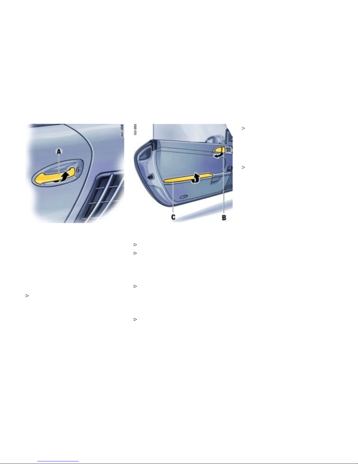
Doors
Automatic lowe ring of the door w indows
If the door windows are c losed, they will be
automatically opened by a few millimeters when
the doors are opened and, when the doors are
closed, they will be closed again. This makes it
easier to open and close the doors and protects
the seals.
Therefore, you should pull the door handle
slowly so that the door window can be lowered
before the door i s open ed.
Opening doors fr om outside
Unlock vehicle with the remote control.
Pull the door handle A slowly so that the door
window can be lowered before the door is
opened.
Opening unlocked doors from insid e
Pull the door handle B slowly so that t he door
window can be lowered before the door is
opened.
Opening locked doors from in side
Slowly pull door handle B twice.
Please observe the chapter ”LOCKING
COND ITIONS” on page 28.
Door storage tray
Opening st orage tray
Open the cover.
Keep the door storage tray C closed while driving
for safety reasons.
Controls, Instrume nts
31
Downloaded from www.ManualsFile.com manuals search engine

A - Light-e mitting diode for alarm system
Alarm System, P assenger
Compartmen t Monitor ing
Readiness for operation
This device complies with:
Part 15 of the FCC Rules
RSS-210 of Industr y Cana da.
Operation is subject to the following two condi-
tions:
1. This device may not cause harmful interfer-
ence, and
2. this device must accept any interference
received, including inte rference that may
cause undesired operation.
Note
The manufacturer is not responsible for any
radio or TV interference caused by unauthor ized
modific ations to this equipment. Such modification
could void the user’s authority to operate the
equipment.
Warning!
Any changes or modifications not expressly
approved by Porsche could void the user’s
autho ri ty to operate this equipment.
The alarm system and passenger compar tment
monitoring system are switched on when the doors
are locked with the key or remote control.
Please observe the chapter ”CENTRAL
LOCKING IN CARS WITH ALARM SYSTEM”
on page 28.
Unlocking the vehicle by using the key in the
door lock and opening the door may activate
the alarm system within 10 s econds.
Switching off th e al arm system if it is
triggered accidentally
Unlock the vehicle with the remote control.
The alarm system and passenger compartmen t
monitoring system are sw itched off automatic ally
when the doors are unlocked.
Functi on indicat ion
If the alarm system is activated, light-emitting
diode A on the dashboard flashes.
If, after locking, the light-emitting diode does
not flash or, aft er ten seconds, it emits double
flashes, t hen not all alarm contacts are closed.
Additionally, a br ief horn signal sounds.
When the doors are unlocked, the alarm system
and passeng er compartment monitoring system
are switched off and the light-emitting diod e goes
off.
When the alarm is armed, the following
areas are m onitored
– Doors
– Front and rear lids
– Glove compartment
– Passenger compartment
If one of thes e alarm contacts is interrupted, the
alarm horn sounds for approximately 3 minutes.
Additionally, the emergency flasher and the pas-
senger compartme nt light flash f or approximately
four minutes. When the alarm is triggered, the
light-emitting diode changes over to double flash-
es.
32Controls, Instruments
Downloaded from www.ManualsFile.com manuals search engine

In order not to limit the action range of the passen-
ger compartment monitoring system:
Do not fold the backrests forward.
Deactivating the passenge r compartment
monitoring system for one lock ing process
If a person or animal remains in the car while it is
locked, the passenge r com partment monitoring
system must be switched off.
Quickly lock car twice. The doors are locked
but can be opened from the inside:
1. Pull inner door handle once to unlock door
lock.
2. Pull inner door handle again to open door.
Note
Inform any person remaining in the car that the
alarm system will be triggered if the door is
opened.
Fault indication
A double horn signal during locking indicates a
defect in the central locking or alarm system.
Have the defect remedied at an authorized
Porsche deal er.
Controls, Instrume nts
33
Downloaded from www.ManualsFile.com manuals search engine
A - Power window in driver’s door
B - Power window in passenger’s door
Power Windows
Readi ness for operation of pow er windows
– When the ignition is switched on (engine
switched on or off) or
– with doors closed and ignition key withdrawn,
but only until door is first opened. One-touch
operation for cl osing the door windows is
availab le only when the ignition is switched on.
Warning!
Risk of an accident.
Do not put anything on or near the windows
that may interfere with the driver’s vision.
Warning!
Risk of injury when the door windows close.
This applies espe cially if the w indows are
closed with the one-touch operation, because
with this function the window goe s up auto-
matic ally.
Make sure that fingers, hands, arms and
other body parts are not in the way when the
windows are closed.
Remove the ignition key to shut off power to
the window switch es when the vehicle is not
attended by a responsible person. Uniformed
persons could injure themselve s by operating
the power window s.
Do not leave children in the car unattended.
Opening/closing windows
Control over rocker switch
The two rocker switches in the driver’s door
and the switch in t he passenger’s door have a
two-stage function.
Opening win dow with the rocker sw itch
Press the rocker switch down to the first stage
until the window has reached the desired
position.
Closing win d ow with the rocker switch
Press the rocker switch upw ards to the first
stage until the window has reached the desired
position.
One-touch operation
Press the rocker switch up wards or down-
wards to the seco nd stage. W indow moves to
its final position. Press a gain to stop the win-
dow in the d esired position.
One-touch operation for closing the passenger’s
window is available once the window is approxi-
mately half-w ay closed.
Anti-c rushing protection
If the door window is blocked during closing, it will
stop and open again by about an inch.
34Controls, Instruments
Downloaded from www.ManualsFile.com manuals search engine

Warning!
Risk of serious personal injuries. If the rocker
switch is pressed again within 10 seconds of
the window being blocked, the window will
close with its full closing force. Anti -crushing
protection is disabled.
Once the anti-crushing protection acts to stop
the window and opens it slightly, do not press
the rocker switch again within 10 seconds
without checking to make sure that nothing is
blocking the path of th e window. The window
will close with full closing force.
One-touch operation is disabled for 10 seconds
after blockage of a side window.
Automatic window lowering
Please observe the chapter ”DOORS” on page
31.
Storing end position of the wind ows
If the battery is disconnec ted and reconnected, the
windows will not be raised autom atically when the
door is closed.
1. Close the windows with the rocker switch
once.
2. Press the rocker switch upwards again to
store the end position of th e windows in the
control unit.
Controls, Instrume nts
35
Downloaded from www.ManualsFile.com manuals search engine
Mirrors
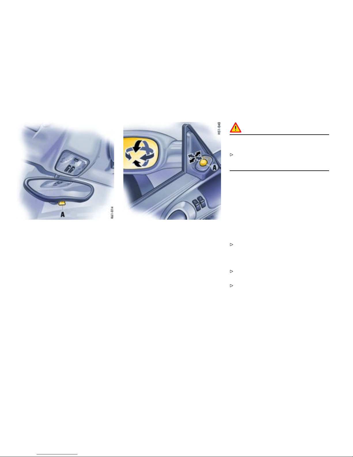
Inside mirror
When the mirror is being adjusted, the anti-glare
lever A must point forward.
Basic position : lever forward
Anti-glare positi on: leve r back
Door mi rrors
Function
Before driving the vehicle, adjust the outside and
inside mirrors. It is important for safe driving that
you have clear, unobstruc t ed vision to the rear.
Warning!
Risk of an accident, resulting in serious
personal injury or death.
Do not put anything on or near the windows or
the mirrors that may interfere with the driver’s
vision.
Adjusting
1. Switch on ignition.
2. By turning the control switch A, select the
driver’s side or the passenger’s side .
3. Move the door mirror glasses in the appropri-
ate direction by tilting the control swit ch.
If the electrical adjus tment facility fails
Adjust mirror by pressing on the mirror face.
Automatically swivelling down mirror on the
passenger ’s side
Please observe the chapt er ”SEAT MEMORY”
on page 43.
Please observe the chapter ”PARKING AIDS”
on page 79.
36Controls, Instruments
Downloaded from www.ManualsFile.com manuals search engine
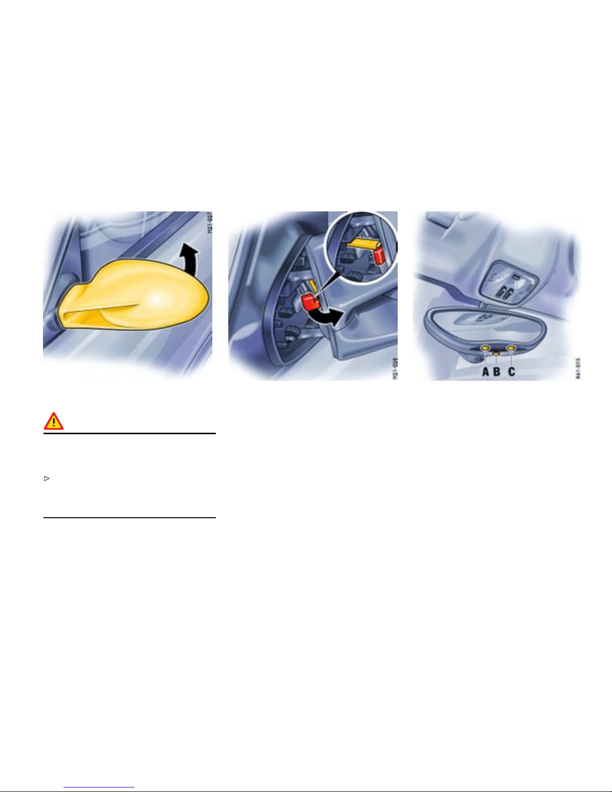
Folding in door mirro r s
Warning!
Danger of injury to ngers if the mirror
accidentally ips back when being folded
in.
Exercise extreme caution when folding in
mirror by hand. Do not let go of the mirror
before the locking lever is locked or the mirror
is fully unfolded.
1. Push mirror towards the door window and
contin ue to hold it (high spring force).
2. Swivel the locking lever up to the st op and
slowly let go of the mirror.
Unfolding door mirrors
1. Push mirror towards the door window and
continue to hold it (high spring force). The
locking lever disengages automatically.
2. Move mirror back to unfolded position by
hand. D o not let go of the mirror beforehand.
A - Sensor
B - Switch for automatic anti-g lare operation
C - Light-em itting diode
Automatic Anti-Glare Interior Mirror a nd
Door Mirrors
Function
Sensors on the front and rear sides of the in terior
mirror measure the incident light. The mirrors
automatically change to anti-glare position or
revert to their normal state, depending on the
light intensity. When reverse gear is selected,
automatic anti-glare operation is switched off.
Controls, Instrume nts
37
Downloaded from www.ManualsFile.com manuals search engine
Note
The incident light in the area of the sensors
must not be restricted, e.g. by stick ers on th e
windshi eld.
Switching off the automatic anti- glare
operation
Press switch B. Light-emitting diode C goes
out.
Switching on the autom atic anti-glare
operation
Press switch B. Light-emitting diode C lights
up.
Warning!
Risk of injury. Electrolyte uid can e merge
from a broken mirror glass. This uid irritates
the skin and eyes.
If the electrolyte fluid should come into contact
with the eyes or sk in, immediately rinse it off
with clean water. See a doctor if necessary.
Warning!
Risk of damage to the paintwork, leather
and plastic parts. Electrolyte uid can be
removed only while it is still wet.
Clean the affected parts with water.
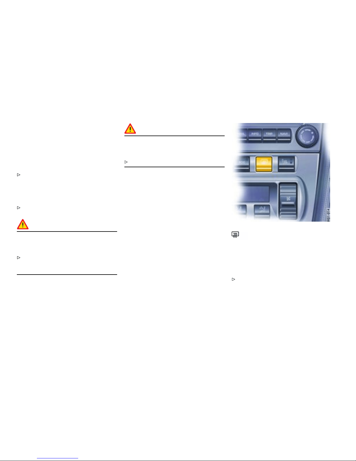
Heated rear window/ Door mirror
heating
The heated rear window/door mirror heater is
ready for operation when the ignition is on.
Switching on
Press b utton. The light-emittin g diode in the
button lights up.
After approx. 15 minutes, the he ater switches off
automatically. The heate r can be switched back on
by pressing the button again.
38Controls, Instruments
Downloaded from www.ManualsFile.com manuals search engine

Seat Adjustment
Gener al information
Warning!
The seat may move unexpectedly if you
attempt to adjust while driving. This could
cause sudden loss of control, resulti ng in
serious personal injury or death.
Do not adjust seats while the vehicle is in
motion. The backrest locks must be engaged
at all times while the vehicle is in motion.
Warning!
Safet y belts only offer protection when
the backrest is upright and the belts are
properly positioned on the body. Improperly
positioned safety belts or safety belts worn
by passengers in an excessiv ely reclined
position can cause serious perso nal injury or
death in an accident.
Do not operate the car w i th the driver or
passenger backrests excessively reclined
(see “Seat position” ).
Seat position
An ergonomically correct sitting position is
important for safe and fatigue-free driving. We
recommend the following procedure for adjusting
the driver’s seat to suit individual requirements:
1. Vehicles with manual transmission:
Adjust the seat until, with the clutch pedal
fully depressed, your leg remains at a slight
angle . Vehicles with Tiptronic S: Adjust the
seat until, with your left foot on the footrest,
your left leg remains at a slight angle.
2. Rest your outstretched arm on the steering
wheel. Set the backrest angle and the steer-
ing-wheel position so that your wrist rests
on the outer rim of the steering wheel. At
the same time, the shoulders must still be in
noticeable contact with the backrest.
3. Adjust the seat height to give yourself enough
headroom and a good overview of the vehicle.
4. Electrically adjustable seat: Adjust the seat
angle until your thighs rest lightly on the seat
cushion.
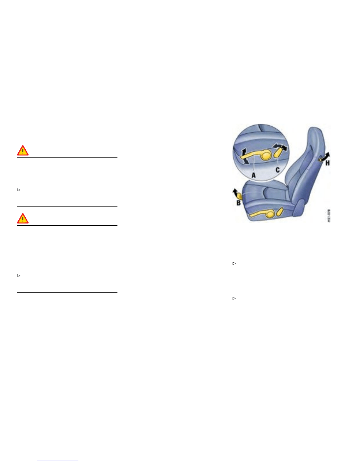
Manually adjustable comf ort seat/sports
seat
A - Seat height
Use lever A in a pumping movement:
Upwards - seat moves upwards
Downwards - seat moves downwards
B - Fore and aft
Raise locking lever B. Move seat to desired
position and release lever. Ensure that the seat
engages correctly.
40Controls, Instruments
Downloaded from www.ManualsFile.com manuals search engine
C - Backrest angle
Operate switch C until the de sired backrest
angle is reached.
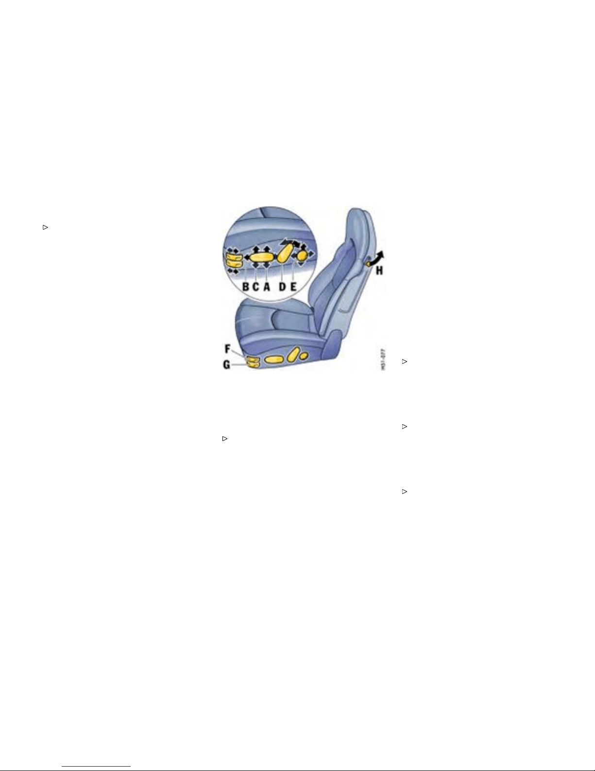
Electr ically adjustable comfort
seat/sports seat
Adjustment
Press the switch in the direction indicated by
the arrow until the desired setting is reached.
A - Seat height adjustment
B - Fore-and-aft position adjust ment
C - Seat angle adj ustment
D - Backrest angle adjustment
E - Lumbar support (pelvis and spinal column
support)
To permit a relaxed sitting posture, the backrest
curvatu re is continuously adjust able in vertical and
horizontal directions for individual pelvis and spinal
column support.
Press the switch in the direction i ndicated by
the arrow until the desired backrest curvature
is reached.
F - Adjus ting the backrest side bolsters
(electrically adjustab le sports seat only)
Push forward or pull backward switch F until
the side bolsters are adjusted to the shape of
the body.
G - Adjusting the seat cushion side bolsters
(electrically adjustab le sports seat only)
Push forward or pull backward switch G until
the side bolsters are adjusted to the shape of
the body.
Controls, Instrume nts
41
Downloaded from www.ManualsFile.com manuals search engine

M - Memory button
1 - Key button
2, 3 - Person buttons
Seat M emory
Individual seat and d oor mirror settings
Individu al seat and door mirror settings can be
stored and recalled for the driver’s position.
Further individual se tting options are available in
vehicles with the Sport Chrono Package Plus.
Please observe the chapter “Individual
Memory” in the separate PCM operating
instructions.
Warning!
Risk of crushing due to uncontrolled recall of
a seat setting.
Cancel automatic adjustment by pressing any
of the seat adjustment buttons.
Do not leave children in the vehicle unattended.
Operation with person buttons 2, 3
Storing seat position
1. Switch on ignition. Reverse gear must not be
engaged.
2. Set the desired seat and door-mirror positions.
3. Keep memory button M depressed and
addition ally press person button 2 or 3. The
individual setting is now stored under the
desired person button.
Recalling seat positio n
The seat position can only be c alled up when the
vehicle is stationary.
1. Switch on the ignition or open the driver’s
door.
2. Press person button until the seat has reached
its final position. The door mirror and the
lumbar support setting will be completed even
if the person button is not kept depressed.
Note
Automatic seat adjustment can be interrupted
immed iately by releasing the button.
Controls, Instrume nts 43
Downloaded from www.ManualsFile.com manuals search engine

Operating with the remote control of the
vehicle k ey
Individual assignment of the remote control
Each remote control (up to six) can be assigned
an individual seat and door mirror position.
The stored seat and door mirror position is set
automatically when the vehicle is unlocked using
the corresponding remote control.
Storing seat position
1. Switch the ignition on with the d esired vehicle
key. Reverse gear must not be en gaged.
2. Set the desired se at and door-mirror pos itions.
3. Keep memory button M depressed and
additionally press key button 1. The individual
setting is now assigned to this remote control
and to the key button.
Storing in dividual lowered position of the
passenger’s door mirror as a parking aid
Once the driver’s seat setting has been stored, an
individual lowered position of the p assenger’s door
mirror may be stored f or driving in reverse:
1. Apply the handbrake.
2. Switch the ignition on with the d esired vehicle
key.
3. Engage reverse gear.
4. Select passenger side with mirror switch. The
passenger’s mirror swivels downwards.
5. Set passenger’s door mirror to desired fin al
position.
6. Keep memory button M depressed and
addition ally press key button 1. The individual
settin g is now assigned to this remote control
and to the key button.
Recalling seat position
Unlock the locked vehicle or the luggage
compartment with the remote control. The
stored seat position is automatically set.
The seat position assigned to a remote control
can also be recalled with the key button 1 if the
corresponding key was used to switch on the
ignition.
If no seat position has been assigned to a remote
control, the key button will not work.
Note on operation
Automatic seat adjustment can be interrupted
immediately:
by switching on the ignition,
by pressing t he central locking button,
by pressing any memory or seat adjustment
button.
Clearing th e stored seat position
1. Switch the ignition on with the desired vehicle
key.
Press memory button twice and key button 1
once consecutively.
44Controls, Instruments
Downloaded from www.ManualsFile.com manuals search engine
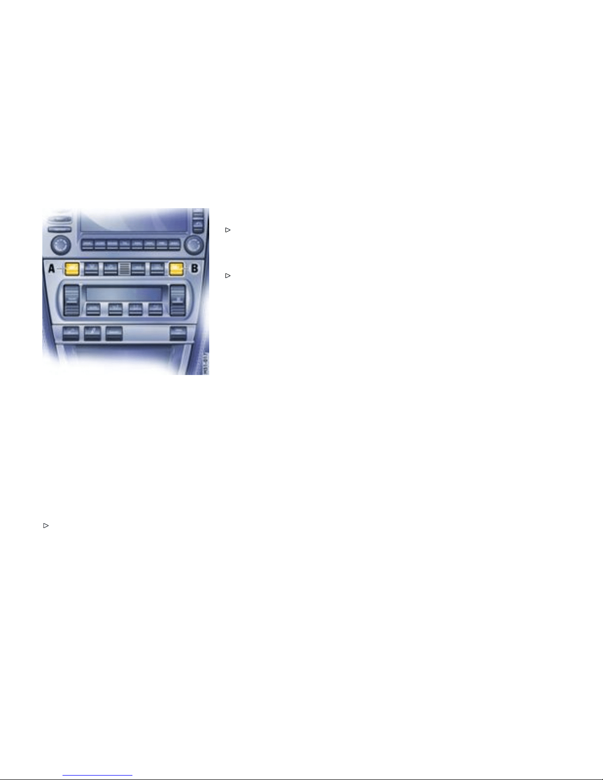
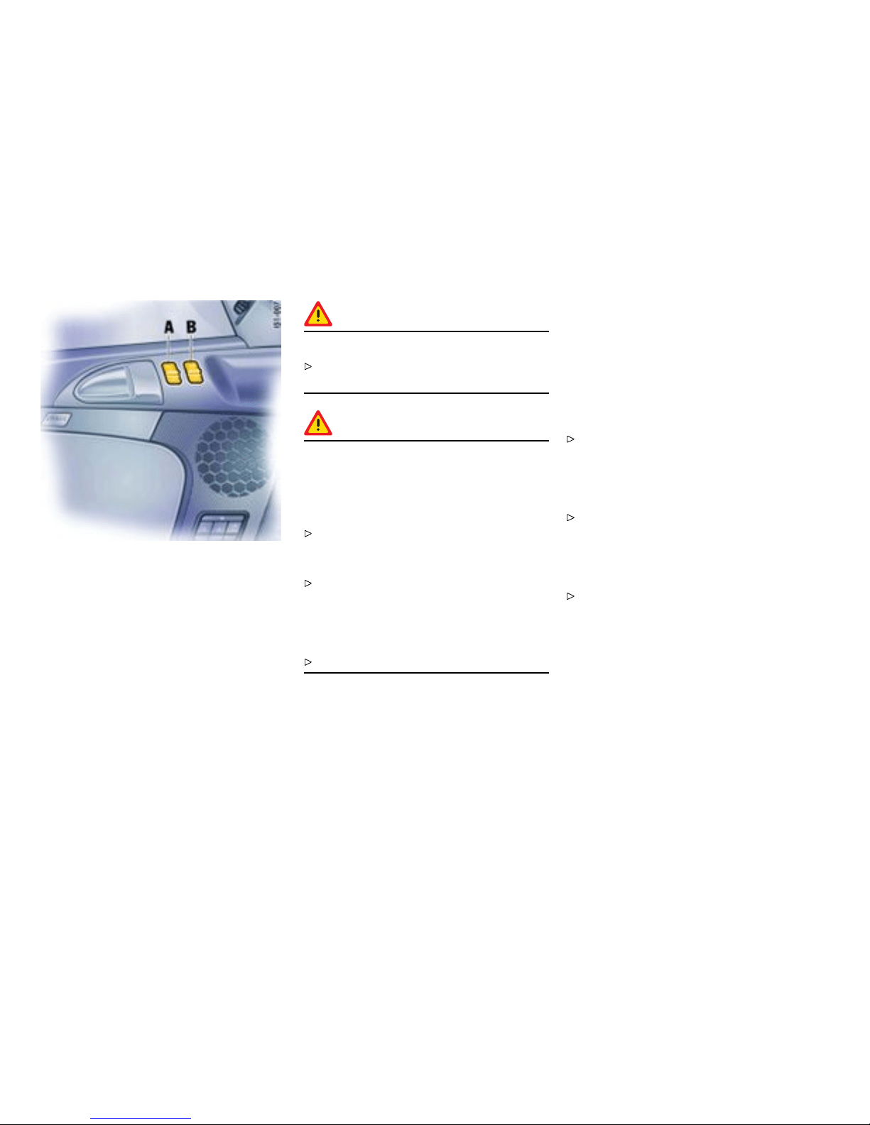
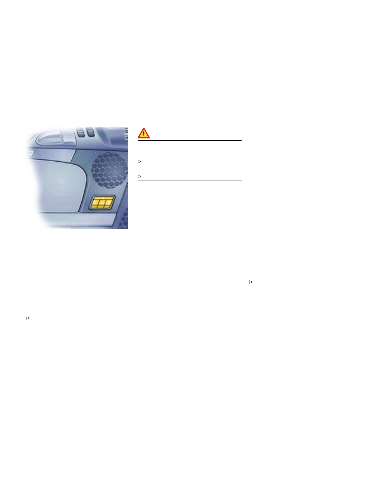
A - Seat heating, left
B - Seat heating, right
Heated Seats
Switching on
Readiness for operation
Two-stage seat heating is ready for operation when
the ignition is on.
High heati ng power
Press button. Both light-emitting diodes in t he
button light up.
Low hea ting power
Press the rocker-s witch symbol again. One
light-emitting diode in the button lights up.
Switching off
Press button. Light-emitting diodes go out.
Controls, Instrume nts
45
Downloaded from www.ManualsFile.com manuals search engine

Steering Wheel Adjustment
Adjusting steeri ng wheel height and
longitudinal direction
Warning!
Risk of accident. The steering wheel may
move further than desired if you a t tempt to
adjust it when driving. You can lose control of
the vehicle, causing serious personal injury or
death.
Do not adjust the steering wheel when driving.
1. Insert t he ignition key fully into ignition lock.
2. Push the locking lever downw ards.
3. Adjust steering wheel to fit the chosen
backrest angle and your seat position by
moving the steering wheel up or down and
longitudinally.
4. Swivel locking lever back until you feel it
engage. If necessary, move the steering wheel
slightly up or down and longitudinally.
46Controls, Instruments
Downloaded from www.ManualsFile.com manuals search engine
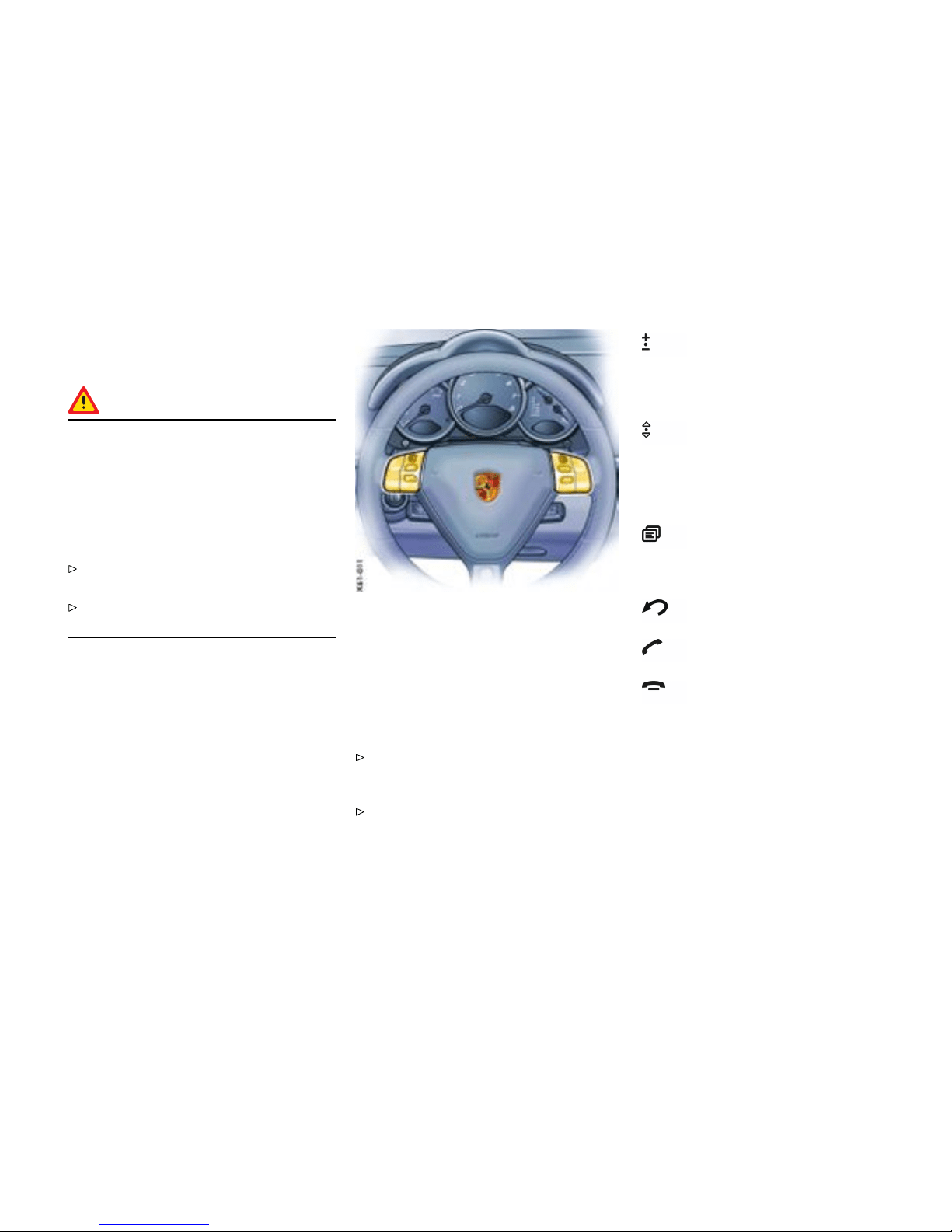
Multi-fun ctional steering wh eel
Function
Warning!
There is a danger of accident if you set or
operate the on-board computer, radio,
navigation system, telepho ne or other
equipment when driving. This could distract
you from the trafc and cause you to lose
control of the vehicle. If loss of vehicle control
is severe enough, serious personal injury or
death could result.
Operate these components while driving only if
the traffic situation allows you to do so safely.
Carry out any complicate d operating or setting
procedures only with the vehicle stationary.
Depending on the equipment in your vehicle, you
can use the function keys of the m ulti-functional
steering wheel to operate the following Porsche
communication systems:
– PCM,
– Telephone,
– Radio with CD drive,
– CD changer.
Readiness for operation of
multi-functio nal steering wheel
The multi-functional steering wheel is ready for
opera tion when the ignition and PCM are switched
on.
Operating the function keys
Please read t he separate PCM operatin g
instructions before operating the function
keys.
The rotary knobs at the top left and right of the
steering whee l can also be pressed.
Turn volume control
Upwards - increase volume.
Downwards - decrease volume.
Press volume control
To switch volume/mute on and off.
Turn rotary knob
To select/mar k function in the PCM. To
do this, turn the rotary knob upward or
downward.
Press rotary knob
To activate selected function.
Press screen button
To call the stored PCM function.
The button can be assigned the desired
function in the PCM.
Press Back button
To move back in the PCM menu.
Press Handset Pickup button
To accept a telephone call.
Press Handset Hangup button
To end or refuse a tel ephone call.
Controls, Instrume nts
47
Downloaded from www.ManualsFile.com manuals search engine
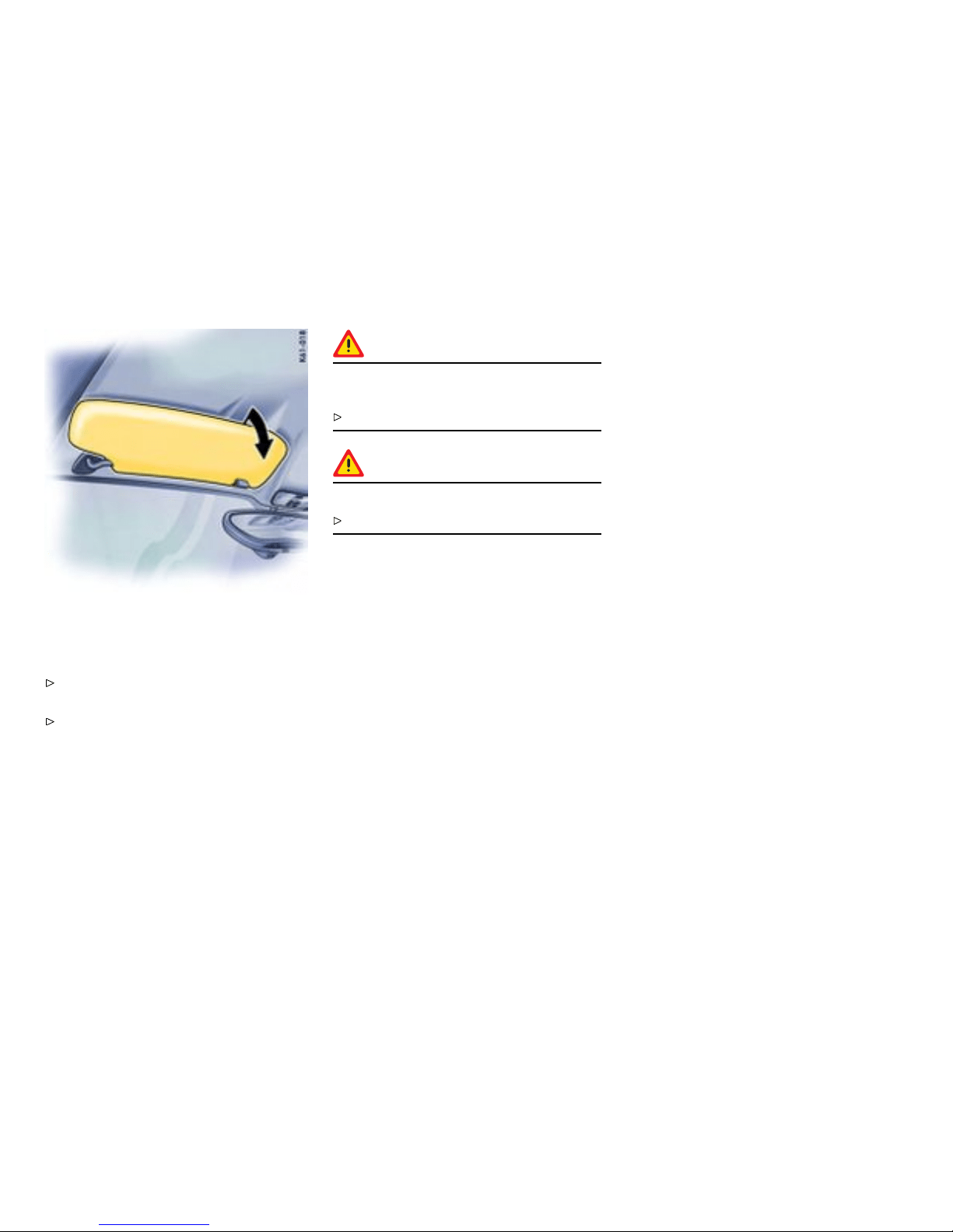
Sun Visors
Swivel the sun visors
Swing the sun visors down to p reven t glare
from the front.
To prevent glare from the side, unclip the sun
visor from the inner bracket and swivel round
so that it is in front of the door window.
Vanity m irror
The vanity mirror on the rear of the sun visor is
covered by a lid.
Warning!
Risk of injury or risk of damage to mirror lid in
an accident.
Keep the lid closed while driving.
Warning!
Risk of damage.
Do not force the lid beyond its end position.
In the case of an illuminated vanity mirror, the light
is switched on when the lid is opene d.
48Controls, Instruments
Downloaded from www.ManualsFile.com manuals search engine
Safety B elts
Gener al information
Warning!
Always make sure your and your passenger ’s
safety belts are properl y fas t ened while the
vehicle is in motion. Failure to follow safety
belt warnings may result in serious personal
injury or death.
For your and your passenger’s protection, use
safety belts at all t imes while the vehicle is in
motion.
Use appropriate child restraint systems for all
small children.
Warning!
Proper wearing of safety belts
Safety belts must be positioned on the body as
to restrain the upper body and lap from sliding
forward. Improperly positioned safet y bel t s
can cause serious personal injury or death in
case of an accident.
The shoulder belt should always rest on your
upper body. The should er belt should never be
worn behind your back or under your arm.
For maximum eff ectivene ss, the l ap belt
should be worn low across the hips.
Pregnant women should position the belt as
low as possible across the pelvis. Make sure it
is not pressing against the abdomen.
Belts should not be worn twisted.
Do not wear belts over ri gid or breakable
objects in or on your clothing, such as eye
glasses, pens, keys, etc. as these may cause
injury.
Several layers of heavy clothing may interfere
with proper positioni ng of belts.
Belts must not rub against sharp objects or
damage may occur to the belt.
Two occupants should never share the same
belt at the same time.
Warning!
Care and maintenan ce
Keep belt buckles free of any obstruction that
may prevent a sec ure locking.
Belts that have been subjected to excess-
sive stretch f orces in an accident must be
inspected or replaced to ensure their contin-
ued effectiveness in restraining you. The same
applie s to belt tensioner systems whic h have
been triggered. In addition, the anchor points
of the belts should be checked.
If safety belts do not work properly, see your
authorized Pors che dealer immediately.
If the belts show damage to webbing, bind-
ings, buckles or retractors, they should be
replaced to ensure safe operation.
Do not modify or disassemble the safety belts
in your vehicle.
The belts must be kept c l ean or th e retractors
may not work properly.
Please observe the chapter ”CAR CARE
INSTR UCTIONS” on pa ge 228.
Never bleach or dye safety belts.
Do not allow safety belts to retract until they
are completely dry after cleanin g or this may
cause damage to the belt.
Controls, Instrume nts 49
Downloaded from www.ManualsFile.com manuals search engine
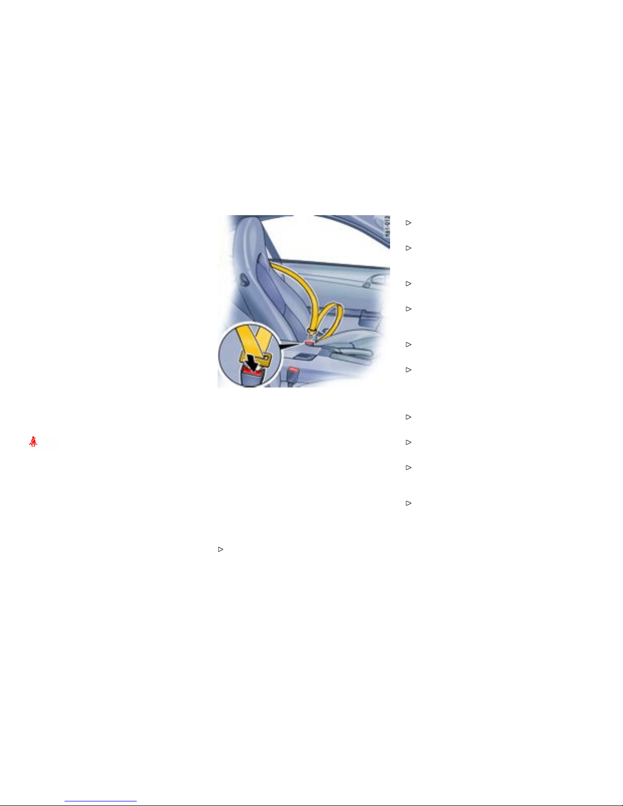
Belt tensioner
Depending on the force of an impact, fastened
safety belts are tightened in an accident.
The belt tensioners are triggered by:
– Front, side and rear impacts of suffici ent
severit y.
Note
The belt tensioner system can be triggered only
once; the system must be replaced afterward.
If there is a fault in th e belt -tensioner system, the
airbag warning light lights up.
Work may be performed on the belt- tensione r
system only by an authorize d Pors che dealer.
Smoke is released when the belt tensioners are
triggered. This does not indicate a fire in the
vehicle.
Safety B elt Warning System
An audio-visual warning system is interconnect-
ed with the driver’s safety belt.
Every time the ignition is turned on, the gong will
sound for about 6 seconds to remind driv er and
passenger to buckle up. In addition, the gong
will sound for approx. 90 seco nds if the vehicle
speed exceeds 15 mph (24 km/h). The safety belt
warning light in the instrument panel and on-board
computer will go off as soon as the driver has
buckled up.
Inertia reel retractor
The combination lap/shoulder belt with inertia reel
locking mechanism adjusts automatically to your
size and movements as long as the pull on the belt
is slow.
Rapid deceleration during hard b raking or a
collision locks the belt. The belt will also lock
when you drive up or down a steep hill or in a sharp
curve, otherwise, the shoulder belt will not inhibit
your upper body movement.
Fastening the safety belt
Assume a comfortable sitting position.
Please observe the chapter ”SEAT POSITION”
on page 40.
The shoulder belt should always rest on y our
upper body. The shoulder belt should never be
worn behind your back or under your arm.
Grasp belt and pull the belt in a continuous
slow motion across your chest and lap.
Insert belt tongue into buckle on inboard si de
of seat. Push down until it securely locks with
an audible click. Pull the be lt to check.
Pull shoulder section to make sure belt fits
snugly across the pelvis.
Belts should fit snugly across the pelvis and
chest. Make sure there is no slack in the belt.
Releasing the safety b elt
Push in release butto n (arrow) on buckle. Be lt
tongue will spring out of buckle.
To release a latched belt, lean back to take the
body pressure off the belt.
To store lap/shoulder belt, allow the belt to
retract as y ou guide the latch to its stowed
position.
Please observe the chapter ”AUTOMATIC
LOCKING RETRACTOR” on page 60.
50Controls, Instruments
Downloaded from www.ManualsFile.com manuals search engine

Safety belts
If it becomes necess ary to cle an the be lts, you can
use any mild washing agent. A llow the belts to dry
prior to retracting, but avoid direct sunlight.
Only use suitable cleaners. If unsuitable
cleaners are used or any att empt is made
to dye or bl each the belts, the webbing may be
weaken ed and th us constitute a safety risk.
Controls, Instrume nts
51
Downloaded from www.ManualsFile.com manuals search engine

Airbag Systems
Gener al information
The airbags in combination with the safety belts
make up a sa f ety system which offers the driver
and the passenger the greatest known protection
from injuries in case of accident. Your vehicle
is equipped with a weight sensing system for
the passenger’s seat in accordance with U.S.
Federal/Canadian Motor Vehicle Safety Standard
208.
Even if your ve hicle is equipped with airba gs, the
safety belts must be worn at all times, because
the front airbag system is only deployed by frontal
collisions with an impact of sufficient s everity.
Below the deployment threshold of the airbag
system, and during types of collisions which do not
cause the actuation of the system, the safety belts
provide the primary protection to t he occupants
when correctly worn. Th erefore, all persons
within the vehicle must wear safety belts at all
times (in many states, state law requires the use of
safety belts).
Please observe the chapter ”SAFETY BELTS”
on page 49.
The front airbags are located under the padded
steering wheel panel on the driver’s side and, on
the passenger’s side, in the dashboard. The side
airbags for the front seats are installed on the
side in the seat backrests. The head airbags are
installed in the door linings.
Danger!
To provide optimal occupant protection, air-
bags must inate at very high speed. If you
are not wearing your safety belt or are too
close to the airbag when it is de ployed, inat-
ing airbags can result in serious personal inju-
ry or death. Improper handling of the weight
sensing system can unintentionally impair
switching the passenger’s airbag off and on.
Make sure there are no people, animals or
object s between the driver or passenger and
the area into which the a irbag inflates.
Sit back as far from the dashboard or steering
wheel as is practical, while still maintaining full
vehicle control.
Always hold the steering wheel by the outer
rim. Never rest your hands on the airbag
panel.
Always fasten seat belts because triggering
of the airbag system depends on the force and
angle of impact.
Do not transport heavy objects on or in front
of the passenger’s seat. These could impair
the function of the airbag, the seat belts, and
weigh t sensin g.
Do not hang objects (e.g. jac kets, coats, coat
hangers) over the backrest.
Always keep the lid of th e doo r stora ge com-
partment closed. Objects must not protrude
out of the door storage compartment.
No changes may be made to the wiring or
components of the airbag system.
Do not add any additional coverings or stickers
to the steering wheel or in the area of the
passenger airbag, side airbags and head
airbags. Doin g so may adversely affe ct the
functioning of the airbag system or cause
harm to the occupants i f the airbag syste m
should deploy.
Do not modify the seat coverings. D o not
attach additional cushions, protective cover-
ings, or pillows to the passenger’s seat. Do
not affix things to the passenger’s seat or cov-
er it w ith other materials. Do not co ver the
back of the backrest. Do not make changes
to the passenger’s seat and to the seat base
frame.
Do not undertake any wiring for electrical
accesso ry equipment in the vicinity of t h e
airbag wiring harnesses. Doing so may
disable the airbag system or cause inadvertent
inflation.
If the warning light comes on, the airbag
system should be repaired immediately by
your authorized Porsche dealer.
52Controls, Instruments
Downloaded from www.ManualsFile.com manuals search engine

Always keep feet in the footwell while driving.
Do not put feet on the dashboard or the seat
area. Do not lean against the inside of the
door or outside the window while the vehicle is
moving.
Using accessories not approved by Porsche
can cause the weight sensing system to be
impaired.
Do not squeeze objects, such as the fire
extinguisher, or f irst aid kit under the seat.
Only have seats removed and installed by
an authorized Porsche dealer so that weight
sensing components will not be damaged .
Give your passenger all of the information in
this chapter.
Note
Airbag components (e.g. steering wheel, door
lining, seats) may be disassembled only by a n
authorized Porsche dealer.
When disposi n g of a used airbag unit, our safety
instruc tions must be followed. These instructions
can be obtained at any authorized Porsc he dealer.
Function of the airbag sy stem
Airbags are a supplemental safety system. Your
primary protection comes from your safety belts.
The front airbags are triggered during a frontal
collision of suffici ent force and direction. In the
event of a side impact of corresponding force, the
side airbag on the impact side is triggered.
The inflatio n process generates the amount of
gas required to fill the airbags at the necessary
pressure in fractions of a second.
Airbags help to protect the head and upper body,
while simultaneously damping the motion of the
driver and passenger in the impa ct directio n in the
event of a frontal impact or side impact.
In order to help provide protection in severe
collisions which can cause death and serious injury,
airbags must inflate extremely rapidly. Such high
speed inflation has a negative but unavoidable side
effe ct, which is that i t can and does cause injuries,
includi ng facial and arm abrasions, bruisin g and
broken bones. You can help minimize such injurie s
by always wearing your safety belts.
There are many types of accidents in which
airbags are not expected to deploy. These include
accidents where the airbags would provide no
benefit, such as a rear im pact against your vehicle.
Other accidents where the airbags are designed
not to deploy are thos e where the risk of injur y from
the airbag deployment could exceed any protective
benefits, such as in low speed accidents or higher
speed accidents where the vehicle decelerates
over a longer time. Since airbag deployment does
not occur in all accidents, this further emphasizes
the need for you and yo ur passenger to always
wear safety belts.
Your vehicle is equipped with a crash sensing and
diagnostic module. This module will record the u se
of the seat belt restraint system by the driver and
passenger when the airbags and/or belt tensioner
work.
Advanced Airbag
Your vehicle is equipped with a weight sensing
system for the passenger’ s seat in accordance
with U.S. Federal/Canadian Motor Vehicle Safety
Standard 208. Depending on the weight acting on
the passenger’s seat, the passenger’s airbag will
automatically be switched on and off.
Depending on the angle and f orce of impact,
the passenger’s airbag which is a ctivated will be
triggered during a collision.
Precondition for switching the passenger’s airbag
on and off, depending on weight:
– Vehicles equipped with key-operated airbag
deactivation device: S witch position AUTO.
– Ignition key is inserted.
Seat adjustment for the passenger’s sea t
If the seat is in an extreme p osition (e.g., the
backrest is in contact with the engine compartmen t
wall), the backrest can warp. Warping of the
backrest can lead to malfunctions.
Controls, Instrume nts
53
Downloaded from www.ManualsFile.com manuals search engine
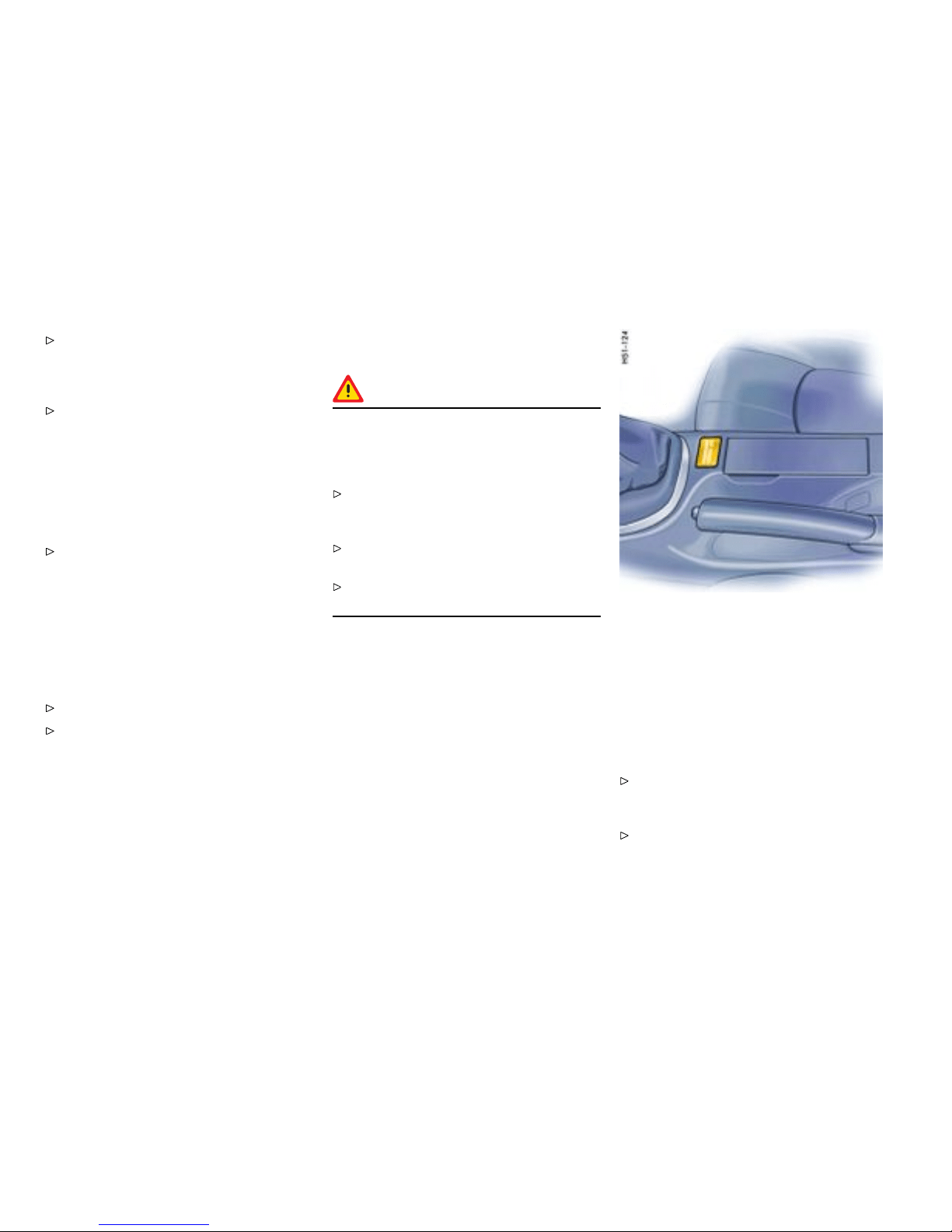
Correct the s eat adjustment . Ensure that the
seat is not jammed and is self-supporting.
Ensure that the backrest i s in the upright
position.
Do not transport a load and objects behind
and under the passenger’s seat. If the load
or objects are un der the s eat, it c an cause
malfunctions.
If the weight on th e passenger’s seat is reduced
significantly, e.g., by supporti ng weight on the
armrest, the passenger’s airbag can be switched
off.
Select an upright seat position, and do not
support weight on the armrests or le an out of
the window. Always keep feet in the footwell
while driving. Do not put feet on the dashboa rd
or the seat area. Do not lean against the inside
of the door o r outside the window while the
vehicle is moving.
If the passenge r’s seat is warped significantly, a
message is displayed on the on-board computer:
Correct the s eat adjustment.
Please obse rve the chapter ”WARNIN GS
ON THE INSTRUMENT PANEL AND THE
ON-BOARD COMPUTER” on page 138.
Automatic deacti vation of the passenger’s
airba gs
Danger!
The use of a child restraint system in the
passenger seat can result in serious personal
injury or death to the child from an airbag
deployment.
Please observe the chapter ”PASSENGER
AIRBAG OFF INDICATOR LAMP DOES NOT
LIGHT UP” on page 55.
Before transporting a child on t h e passenger’s
seat:
Please observe the c hapter ”CHILD
RESTR AINT SYSTEMS” on page 58.
– When an up to one-year old child is seated
in the child restraint system, the front airbag
is automatic ally deactivated on the passenge r
side.
– When an adult is seated in the f ront seat the
front airbag remains active on the passenger‘s
side.
Note on operation
Although not desired, it can occur in the case of
heavier children that the passenger airbags remain
active or, in th e case of very light adults or young
persons , that the passenger airbag is deactivat ed.
The condition of the passenger’s airbag system is
shown by the indicator lamp.
If in do ubt:
Please observe the chapter ”PASSENGER
AIRBAG OFF INDICATOR LAMP DOES NOT
LIGHT UP” on page 55.
Please observe the chapter ”KEY-OPERATED
AIRBAG DEACTIVATION DEVICE” on page 56.
54Controls, Instruments
Downloaded from www.ManualsFile.com manuals search engine

Please obse rve the chapter ”CHILD
RESTRAINT SYSTEMS” on page 58.
Please observe the chapter ”LATCH SYSTEM”
on page 62.
Note
After inserting the ignition key, the PASSEN-
GER AIRBAG OFF warning light lights up for a
few seconds as a bulb check.
PASSE NGER AIRBAG OFF indicator lamp
lights up
– The passenger’s airbag is switched off.
PASSE NGER AIRBAG OFF indicator lamp
does not light up
– The passenger’s airbag is active and ready for
operation.
– If the passenger’s seat is n ot occupied, the
PASSENGER AIRBAG OFF indicator lamp will
also not light up, even though the passenger’s
airbag is switched off.
Danger !
Risk of serious personal injury or death
due to the passenger airbag triggering
unintentionally. When the ignition is on a nd
the up to one-year old child is seated in the
child restraint system on the passenger’s
seat, the indicator lamp „PASSENGER AIRBAG
OFF“ must be on. If the “PASSENGER AIRBAG
OFF” indicator lamp does not light up, it could
indica te a fa ult in the system. In this case:
On vehicles with key-opera ted airbag deactiva-
tion device: Switch to position OFF.
On vehicles without key-operated airbag
deactivation device: D o not drive.
Have the fault remedie d at your nearest
authorized Pors che dealer.
Note
The key switch for switching off the passenger’s
airbag in combinati on with the LATCH attachment
bracket are not installed at the factory. They can
be retrofitted.
Please see your authorized Porsche dealer.
Warn ing light and wa rning
message
Faults are indicated by a warning light in the
instrument panel and a me ssage on the on-board
computer.
Please observe the chapt er ”WARNINGS
ON THE INSTRUMENT PANEL AND THE
ON-BOARD COMPUTER” on page 138.
In the following cases you shou l d imme-
diately consult an authorized Porsche
dealer in order to assure the airbag sys-
tem is functioning properly:
– If the warning light does not light up when the
ignition key is inserted or
– If the warning light does not go out on ce the
engine is running or
– If the warning light appears while driving.
Airbag m aintena nce
In order to ensure long-term functi oning, the airbag
system must be inspected by an authorized
Porsche dealer at the intervals recommended in
your Maintenance Booklet.
Note
If you sell your Porsche, notify the purchaser that
the vehicle is equipped with airbags, and refer
them to the chapter, “Airbag Systems“, in the
Owner’s Manual (safety and disposal rules).
Controls, Instrume nts
55
Downloaded from www.ManualsFile.com manuals search engine
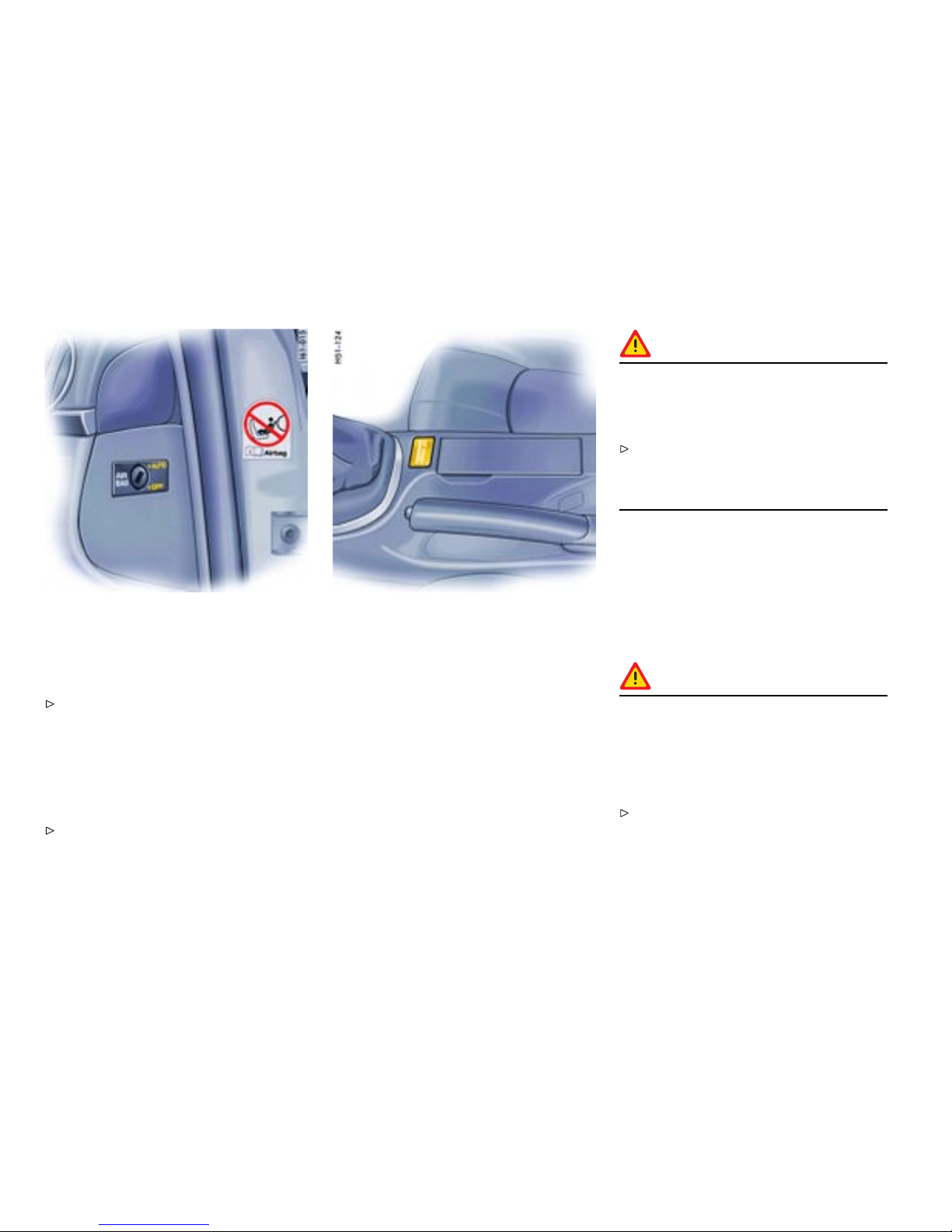
Further information on the airb ag system can be
found on stickers attach ed to the sun viso rs.
For special recommendations on the use of child
restraints:
Please observe the chapter ”CHILD
RESTRAINT SYSTEMS” on page 58.
Key-operated airbag deactivation device
If in doubt about the status of the airba g, you
can switch off the passenger’s airbag on the key
switch.
Switch off the passenger’s airbag on the key
switch using the vehicle key.
Switch position AUTO - pass enger’s airbag system
is active
Switch position OFF - passenger’s airbag system is
switched off
Danger!
Risk of serious personal injury or death for
passenger if passenger’s airbag remains
switched off after the child restraint system is
removed.
Make sure that the key switch is switched to
AUTO once the child seat has been removed,
in order to provide protecti on to the adult
occupants.
Warning light “PASSENGE R AIRBAG OFF”
If the airbag on the passenger’s side is switched
off:
– Warning light “PASSENGER AIRBAG OFF”
is continuously lit when the ignition key is
inserted.
Danger!
Risk of serious personal injury or death from
the passenger’s airbag. If the “PASSENGER
AIRBAG OFF ” warning light is n ot lit when the
ignition key is inserted and the Airbag OFF
switch is switched to the OFF-Position, this
could indicate a faul t in the system.
Do not install a child restraint system on the
passenger’s seat.
56Controls, Instruments
Downloaded from www.ManualsFile.com manuals search engine

Have the fault remed ied immediately. Pl ease
see your authorized Porsche dealer.
Note
The key switch for switching off the passenger’ s
airbag in combination with the LATCH attachment
bracket are not in stalled at the factory. They can
be retrofitted.
Please see your authorized Porsche dealer.
Controls, Instrume nts
57
Downloaded from www.ManualsFile.com manuals search engine
Child R estraint Systems
Porsche recommends that all infants and children
be restrained in child restraint systems at all times
while the vehicle is in motion in accordance with
applicable laws.
Use only child restraint systems with the LATCH-
system recommended by Porsche. These systems
have been tested and adjusted to the interior
of your Porsche and the appropriate child age
groups. Other systems have not been tested and
could entail an increased risk of injury or death.
You can obtain child seats that are LATCH compati-
ble at your authorized Pors che dealer.
Always observ e the separate installation
instructions for your child seat.
The use of infant or child restraints is required by
law in all 50 states of the U.S. and all Canadian
provinces. The child restraint system should be
one that complies with U.S. Federal/Canadian
Motor Vehicle S afety Standards and should
be secured by a lap belt or lap belt p ortion of a
lap-shou lder belt or for child seats equipped with
the LATCH sytem (Lower Anchorage and Tether
for Children, also known as ISOFIX) to the L ATCH
anchorages. A statement by the seat manufacturer
of compliance with this standard can be found
on the instruction label on the restraint and in the
instruction manual provided with the restraint.
Danger!
The use of a child restraint system in the
passenger seat can result in serious personal
injury or death to the child from an airbag
deployment. To reduce risk of injury from
an inating airbag in an accident, Porsche
strongly recommends:
Please observe the chapter ”PASSENGER
AIRBAG OFF INDICATOR LAMP DOES NOT
LIGHT UP” on page 55.
Please observe the c hapter ”CHILD
RESTR AINT SYSTEMS” on page 58.
Note
The key switch for switching off the passenger’s
airbag and the LATCH attachment bracket are not
installed at the factory. They can be retrofitted .
Please see your authorized Porsche dealer.
Danger!
Risk of serious personal i njury or death to the
child.
Follow all child restraint instructions and
warnings in this manual.
– When using an infant or child restra int system,
be sure to follow all manufacturer’s instruc-
tions on installation and use.
– Infants and small children should never be held
on the lap, nor should they share a saf ety belt
with another occupant while the vehicle is in
motion.
– Children too big f or child restraint systems
should use regular safety belts. A shoulde r
belt can be used providing it does not cross
the face or the nec k of the child.
– Choose a child restraint system according to
the age and size of the child.
– Child restraint systems that are damaged or
have been heavily stressed in an accident must
be replaced immediately.
– Do not affix things to child restra int systems or
cover it with other materials.
– Your au thorized Porsche deal er will be glad
to advise you about the installation possibili ty
for a P orsche child restraint system which
allows a key-operated airbag deactivation of
the passeng er’s airbag.
– The key-operated airbag deactivation device
installation requires special programming
available only from your authorized Porsche
dealer.
Please observe the chapter ”KEY-OPERATED
AIRBAG DEACTIVATION DEVICE” on page 56.
58Controls, Instruments
Downloaded from www.ManualsFile.com manuals search engine

Direction of installation for child restraint
systems
Children up to 9 months old
Children of this age mus t be transported in a
restraint system which is installed on the passen-
ger’s seat facing rearward.
The passenger’s airbag must be deactivated.
Children aged between 9 months and 6 years
Children of th is age are held in child restraint
systems facing forward.
The passenger’s airbag must be deactivated
when these systems are used on the passen-
ger’s seat.
Children aged between 6 and 12 years
Children of th is age are held in child restraint
systems facing forward.
The passenger’s airbag must be deactivated
when these systems are used on the passen-
ger’s seat. The passenger’s airbag must be
activate d for children weighing over 59 lbs.
(27 kg).
Note
If a child seat with top tether is ad apted for use on
the passenger’s seat, the anchor point must be
used for anchoring the top tether.
Please obse rve the chapter ”CHILD
RESTRAINT ANCHORAGE” on page 63.
Using child restraint systems in the
passenger seat
Danger!
The use of a child restraint system in the
passenger seat can result in serious pers onal
injury or death to the child from an airbag
deployment. To reduce risk of injury from
an inating airbag in an accident, Porsche
strongly recommends:
Please observe the chapter ”PASSENGER
AIRBA G OFF INDICATOR LAMP DOES NOT
LIGHT UP” on page 55.
Please observe the chapter ”CHILD
RESTRAINT SYSTEMS ” on page 58.
Child re straint system for up to one-year old
children
– Make sure that the PASSENGER AIRBAG OFF
indicator lamp lights up.
– Adjust the passenger’s seat as far away from
the airbag as possible.
Controls, Instrume nts
59
Downloaded from www.ManualsFile.com manuals search engine

Danger!
Risk of serious personal injury or death
due to the passenger airbag triggering
uninten t i onally. Whe n the ignition is on and
the up to one-year old child is seated in t he
child restraint syste m on the passenger’s
seat the indicator lamp „PASSENGER AIRBAG
OFF“ must be on. If the “PASSENGER AIRBAG
OFF” indicator lamp does not light up, it could
indicate a fault in the system. In this case:
Do not use a child restraint system on the
passenger’s seat.
On vehicles with key-oper ated airbag deactiva-
tion device: Switch to position OFF.
Have the fault remedied at yo ur nearest
authorized Porsche dealer.
Child restra int system for children older than
one year
Your vehicle is equipped with a weight sensing
system for the passenger’s seat in accordance
with U.S. Federal Motor Vehicle Safety Standard
208. Depending on the weight acting on the
passenger’s seat, the passenger’s airbag will
automatically be switched on or off.
Small adult passeng ers
Make sure that the PASSENGER AIRBAG OFF
indicator lamp does not light up.
Danger!
Risk of serious personal injury or death due
to the passenger’s airb ag not triggering.
When the ignition is on and the small adult
passenger is seated on the passenger’s seat,
the indicator lamp “PASSENGER AIRB AG OFF”
must be off. If the “PASSENGER AIRBAG OFF”
indica t or lamp lights up, it could indicate a
fault in the system. In this case:
Do not carry a passenger in the passenger’s
seat.
Have the fault remedi ed at th e nearest
authorized Porsche dealer.
Automatic locking retractor
The safety belt for the passenger is equipped
with an automatic locking retractor for securing
the child restrai nt system. When activated, this
retractor allows you to securely fasten the child
restraint system in place so t h at inadvertent
movements will not occur.
Before transporting a child on the passenger’s
seat:
Please observe the chapter ”CHILD
RESTRAINT SYSTEMS” on page 58.
60Controls, Instruments
Downloaded from www.ManualsFile.com manuals search engine

Danger!
Risk of serious personal injury or death to
the child, when excessive force is actin g on
the passenger’s seat due to the seat belt. In
such cases, the passenger’s airbag can be
switched on unintentionally.
After fastening the child restraint system, do
not adjust the seat.
Check the condition of the passenger’s airbag
system shown by the indicator lamp in th e
central console.
Activating the automatic locking retractor
1. If a ch ild restraint system must be fastened to
the passenger’s seat, adjust the passenger’s
seat as far aw ay from the airbag as possible.
2. Fasten child seat.
3. Pull the safety belt retra ctor completely out. At
this point the locking mechanism is activated.
4. Insert the safety belt tongue into the buckle
and make certain that i t is properly latched.
Make no more adjustments to the seat.
5. Allow the safety belt to retract until it is t ight
on the child restraint system. You may further
tighten the belt by pulling on it to allow more
of it to retract. Make sure that excessive seat
belt forces do not occur by moving the seat
with the child seat installed.
Releasing the safety b elt
1. Unbuckle the safety belt latch.
2. Then make certain that the belt has fully
retracted. At this point the automatic locki n g
feature will be disengaged. Seek appropriate
advice from your authorized Porsche dealer
about the possible installation of a Porsc he
child restraint system.
Controls, Instrume nts
61
Downloaded from www.ManualsFile.com manuals search engine
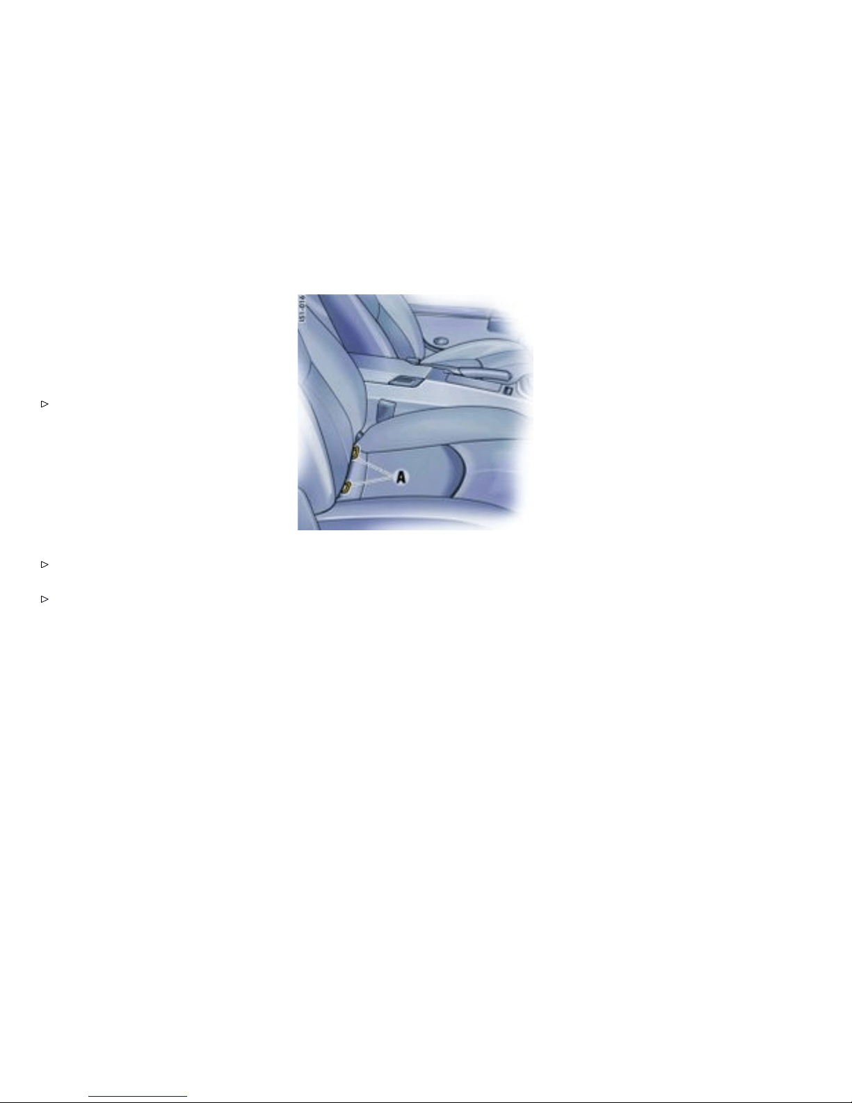
LATCH System
Child seat bracke t on the passeng er’s seat
The key switch for switching off the passenger’s
airbag and the LATCH attachment bracket are not
installed at the factory. They can be retrofitted.
Please see your authorized Porsche dealer.
Porsche recommends the use of a Porsche
Child Seat with Lower Anchorage and Tether for
Children system (LATCH). These systems have
been tested and adjusted to the interior of your
Porsche and the appropriate child age groups.
Other systems have not been tested and could
entail an increased risk of injury.
You can obtain child seats that are LATCH compati-
ble at your authorized Pors che dealer.
Always observ e the separate installation
instructions for your child seat.
Please observe the chapter ”CHILD
RESTRAINT SYSTEMS” on page 58.
Insta lling a LATC H child seat system
1. Secure the child seat to retaining lugs A as
outlined in the instruction manual for the child
seat.
2. Pull the child seat to check that both fastening
points are engaged correctly.
Note
Make sure that the key sw itch is s witched to AUTO
once the child seat has been removed, in order to
provide protection to th e adult occupants.
62Controls, Instruments
Downloaded from www.ManualsFile.com manuals search engine
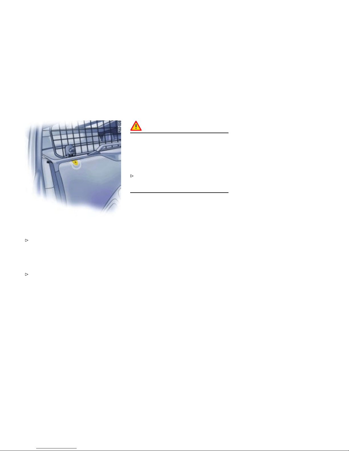
Child R estraint Anchorage
Please obse rve the chapter ”AUTOMATIC
LOCKING RETRACTOR” on page 60.
If your child restrain t seat requires the use of a
tether strap, you will want to use the ancho r point
behind the passenger’s seat under the carpet.
To ensure proper installa tion, see your
authorized Porsche dealer.
Note
If a child seat with top tether is ad apted for use on
the passenger’s seat, the anchor point must be
used for anchoring the top tether.
Warning!
The child restraint anchorage is designed
to withstand only the load imposed by a
correctly tted child restraint. Under no
circumstances is the anchorage to be used
for adult safety belt or harness. Such use
could result in serious injury or death.
Do not misuse the child restraint anchorage.
This is not designed to withstand a load
imposed by an adult.
Controls, Instrume nts 63
Downloaded from www.ManualsFile.com manuals search engine

Clutch Pe dal
The clutch pedal must be depressed fully
before the star ter will engage.
Warning!
Risk of an accident .
Always check the movement of the clutch
pedal before driving and make sure that it is
not obstructed by a floor mat or any other
object.
Secure the floor mat to prevent it from sliding
into positions that could interfere w ith the safe
operation of your vehicle. Your Porsche dealer
will be glad to offer you nonskid floor mats of
the correct size.
Warning!
To avoid damage to the clutch and transmis-
sion:
Always depress the clutch pedal fully when
changing gears.
Do not hold the car on a steep grade with the
clutch pedal par tially depressed.
Should the free travel of the clutch pedal suddenly
become larger, it could mean a malfunction of the
clutch.
See your Porsche dealer for correction.
64Controls, Instruments
Downloaded from www.ManualsFile.com manuals search engine
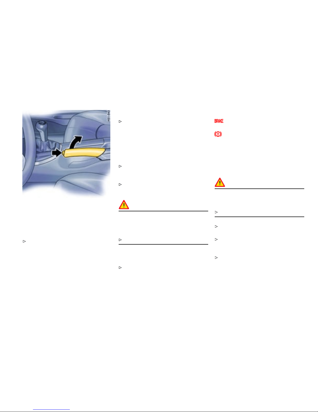
Parking Brake
Function of the parking brake
Parking brake force is mechanically transferred to
the rear wheels by m eans of cables.
Use the parking brake only after the vehicle
has come to a full stop.
Setting the parking brake
Pull the lever all the way up (see arrow). With
the ignition on, the parking brake warning
lights in the i nstrument panel and on-board
computer will come on if the lever is even
slightly raised. A firm pull u p ward is required
to properly engage the parking brake. If the
brake is not fully set, the vehicle may roll
without control.
Move the selector lever to “P” (Tiptronic) or
move the gearshift lever to reverse or first
gear (Manual transmission).
Before exiting the vehicle, make sure that the
parking brake is fully set and the vehicle is not
moving at all.
Danger !
Risk of serious personal injury or death. A
partially engaged parking brake may allow
the vehicle to roll, causing serious personal
injury or death to any person in its path.
Engage the parking brake fully.
Relea sing the parking brake
Pull the lever slightly up as you depress the
release button, and then push the lever all the
way down.
Warni ng lights
Parkin g brake warning light USA
Parking brake warning light Canada
The warning lights in the instrument panel and
on-board computer will go out after the parking
brake is fully released. The warning lights are not
an indicator that the parking brake is fully set; it
is only intended to be a warning to release the
parking brake before driving the car.
Caution!
A partially engaged brake will overheat the
rear brakes, reduce their effectiveness and
cause excessive wear.
Release the parking brake fully.
When parking your car, always set the parking
brake by pulling all the way up on the lever.
Move the selector lever to “P” (Tiptronic) or
move the gearshift lever to reverse or first
gear (Manual transmission).
On hills also turn the front wheels towards the
curb.
Controls, Instrume nts
65
Downloaded from www.ManualsFile.com manuals search engine
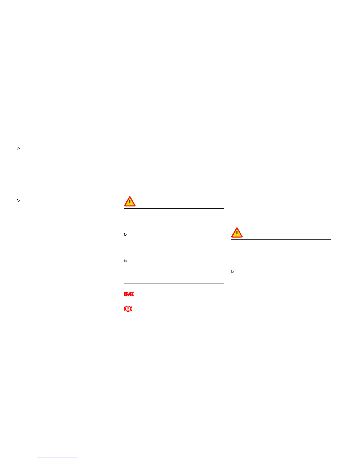
Brakes
Gener al information
Make it a habit to check the operation of your
brakes before driving.
Keep in mind that the braking distance increases
very rapidly as the speed increases. At 60 mph
or 100 km/h, for example, it is not twice but four
times longer than 30 mph or 50 km/h. Tire traction
is also less effective when the roads are wet or
slippery.
Therefore, always maintain a safe distance
from the car in front of y ou.
Vehicles without P orsche Ceramic
Composite Brake (PCCB)
Even though the brake discs consist of alloyed
grey cast iron, they will unavoidably s tart to
corrode if your car is parked for an extended
period. The brakes will tend to “ rub” as a result.
The nature, extent and effects of corrosion depend
on the amount of t ime the vehicle was parked,
whether granular or liquid road salt was spread
and whether grease-dissolving agents were used
in car washes. If the braking comfort is no ticeably
impaired, we recommend having the brake system
checked by experts at an authorized Porsche
dealer.
Brake system function
Your Porsche is equipped with a power assisted
hydraulic dual circuit bra ke system with disc
brake s at the front and rear. Both circuits function
independently. One brake circuit operates the front
and the other operates the rear.
If one brake circuit has failed, the other will still
operate. However, you will notice an increased
pedal travel when you apply the brakes. Failure of
one brake circuit will cause the stopping distance
to increase.
Warning!
Risk of an accident, resulting in serious
personal injury or death. In the unlikely event
of hydraulic failure of one brake circuit:
Push the brake pedal down firmly and hold it in
that position. A mechanical linkage activates
the second circuit, and you will be abl e to bring
the vehicle to a stop.
After bringing your vehicle to a complete stop,
avoid driving the vehicle and instead have
it towed to the nearest authorized Porsche
dealer for repair.
Brake warn ing light USA
Brake warnin g light Canada
If the warning lights in the instrument panel and
on-board computer go on while driving, the brake
fluid level may be too low, or (if the brake pedal
travel has increased) one of the two brake circuits
may have failed.
A greate r braking pressure will be required,
stopping distances will be longer and the braking
behavior will change, particularly in curves.
With correctly adjusted brakes, and a correctly
working brake system, the pedal travel to the point
of brake actuation should be 1-3/16" to 1-9/16"
or 30 to 40 mm. Whenever the brake pedal travel
exceed s this distanc e, have the brake system
checked.
Brake pedal
Warning!
Risk of an accident, resulting in serious
persona l injury or death. Any obstruction of
the brake pedal could increase the stopping
distan ce.
Always check the movement of the brake
pedal before driving and make sure that it is
not obstructed by a floor mat or any other
object.
66Controls, Instruments
Downloaded from www.ManualsFile.com manuals search engine

Secure the flo or mat to prevent it from sli ding
into positions that could interfere with the safe
operation of your vehicle. Your Porsche dealer
will be glad to offer you nonskid floor mats of
the correct size.
Note
In case one of the two brake circuits fails,
increased pedal travel is required to bring your
vehicle to a full stop.
Warning!
To avoid overheating and premature wear of
the brakes:
Before descending a steep grade, reduce
speed and shift the transmission into a lower
gear or driving position to control speed.
Do not ”ride the brakes” by resting your foot
on the pedal when not intending to apply brake
pressure.
Do not hold the pedal down too long or too
often. This could cause the brakes to get hot
and not function properly.
Brake bo oster
The brake booster assist s braking only when
the engine is running.
When the car is moving while the engine is not
running, or if the brake booster is defective, more
pressure on the brake pedal is required to bring
the car to a stop. If this happens, ABS and PSM will
also not operate.
Moistu re or road salt on brakes affects braking.
When the vehicle is driven on salted roads for
extended periods, the brakes should be washed
down thoroughly about every 2 weeks. An auto-
matic carw as h fac ility cannot do this job properly.
Brakes will dry after a few cautious brake applica-
tions.
Warning!
Risk of an accident, resulting in serious
personal injury or death. Driving through
water may reduce traction. Moisture on
brakes from road water, car wash, or coating
of road salt may affe ct braking efciency.
Cautiously apply brakes to test brakes after
being exposed.
Brake wear
Your car has excel lent brakes, but they are still
subject to wear. The rate at which they wear
depends on how the brakes are used.
Have the brake system inspected at the
intervals recommended in your Maintenance
Booklet.
Warning light USA
Warning light Canada
If the warning lights in the instrument panel and
on-board computer stay on when the engine is
running or come on while driving, the brake pads
are worn, excessively.
Do not continue to operate the vehicle. Have
your authorized Porsche dealer inspect or
replace the brake pads.
Controls, Instrume nts 67
Downloaded from www.ManualsFile.com manuals search engine

Brake pads
Wear on the brake pads and brake discs depends
to a great extent on the driving style and the c ondi-
tions of use and therefore cannot be e xpressed in
actual miles on the road.
The high-performance brake system is designed
for optimal braking effect at all speeds and
temperatures. Certain speeds, braking forces
and ambient condition s (such as te mperature and
humidity) therefore might cause ”brake noises“.
New brake pads or linings
New brake pads and brake discs have to be
“broken in”, and therefore only attain optimal
friction when the car has covered several hundred
miles or km. The slightly reduced braking ability
must be compensated for by pressing the brake
pedal harder. This also applies whenever the brake
pads and brake discs are replaced.
68Controls, Instruments
Downloaded from www.ManualsFile.com manuals search engine
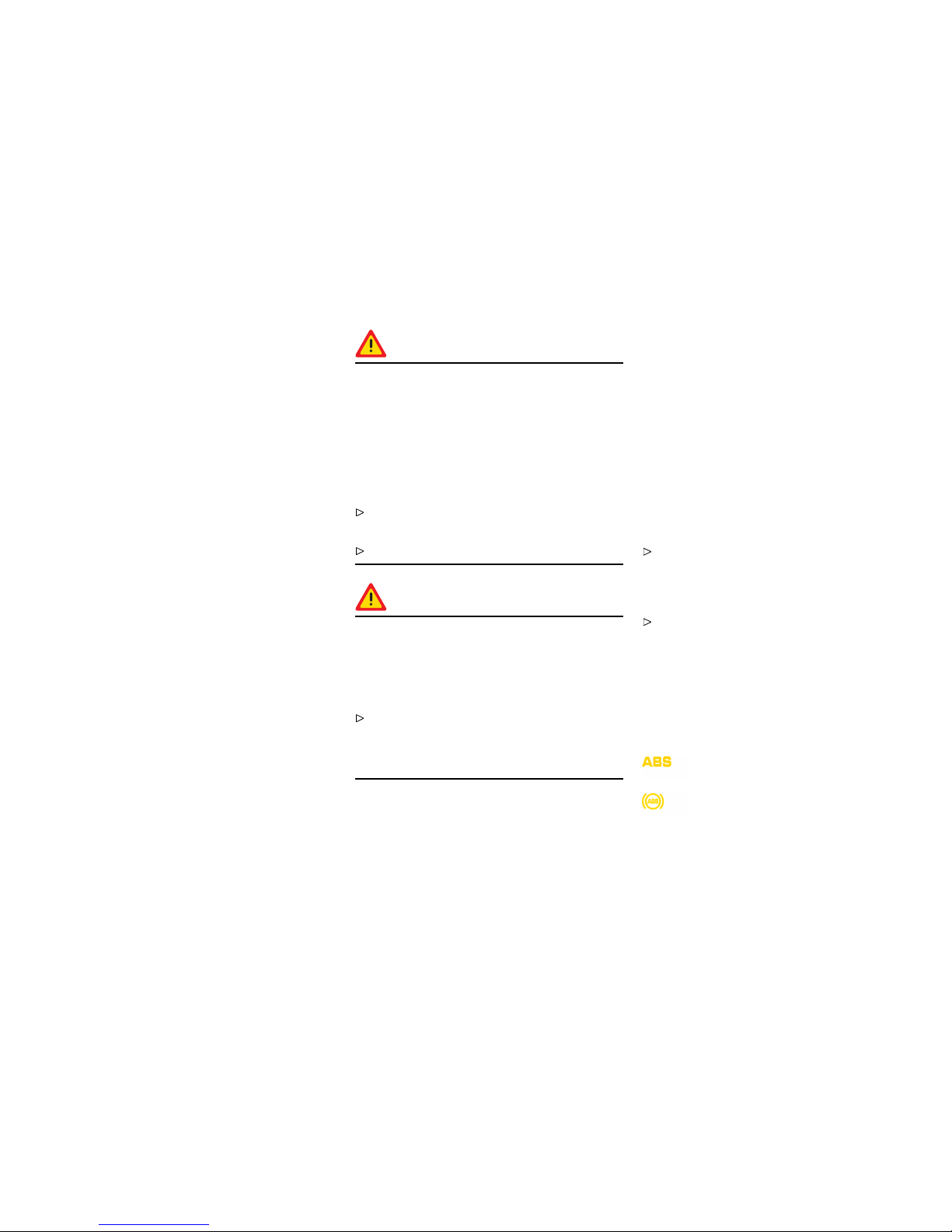
ABS Bra ke System
(Antilock Brake System)
The ABS system represents a major contribution to
the enhancement of active safety in your vehicle.
This system prevents the wheels from locking in a
panic stop on almost all road surfaces.
With the A BS system i n your vehicle, the
following areas ar e enhanced:
Steering, vehicle remains steerable under all
braking forces when ABS is engaged.
Good directional control, no swerving caused by
locking of wheels under braking cond itions.
Shorter stopping dista nce, stopping distances
are usually reduced because controlled braking is
maximized.
Prevention of wheel lock up, no brake- induced
sliding and thus no localized tire wear from
emergency b raking.
The crucial advantage of the ABS system over
a conventional brake system is in the area of
maintaining directional control and maneuverabili ty
of the car in emergency situations.
Warning!
The increased control that is provided sho uld
not induce you to take greater risks with
your safety. The limits dictated by the laws of
physics cannot be overcome, even with ABS.
The risk of accidents due to inappropriate
speed cannot be reduce d, even by the ABS.
The driver bears the responsibility for all
driving maneuvers.
Adapt your driving style to the prevailing road
and weather condit ions.
Obey all traffic laws.
Warning!
Other vehicles not equipped with the ABS
system may not be able to maintain control,
especia lly on wet or poor road surf aces and
thus may be more likely to impact you from
behind.
To minimize that risk, use your ABS system
to increase your ability to maneuver to avoid
dangerous situations and not merely to try to
stop in the shortest distan ce possible.
Operation of the ABS sys tem
A wheel speed sensor is mounted to each of the
four wheels. If wheel lock-up of either of the front
wheels or the rear wheels is sensed during braking,
the brake pressure is adjust ed automatica lly until
the wheel no longer slips.
If braking forces approach the wheel lock-up point
for all wheels (panic braking) the ABS system will
intervene to provide a rapid rythmic braking. The
proper operation of ABS i s perceived by the driver
as a pulsating brake pedal in conjunction with
audible noise and perhaps some vibration.
If you experience these sensations while
driving or a road surface with questionable
traction, reduce vehicle speed appropriate for
the prevailing road conditions.
If full braking should be necessary, press the
brake pedal all the way down throughout the
entire braking procedure, regardless of the
pulsating pedal. Do not ease up on pressure
applied to the pedal.
The functional readiness of all the main electric al
components of the ABS is checked by an electronic
monitoring system both before and while you drive.
Warning light USA
Warning light Canada
When the ignition is switched on the ABS warning
light will light up while the system is el ectronically
Controls, Instrume nts
69
Downloaded from www.ManualsFile.com manuals search engine

interrogated and goes out when the engine is
started if the check is no t yet complete. If the
ABS warning lamp fails to go out, this indicates
that ABS has been deactivated due to a fault. If
the warning lights in the instrument panel and
on-board computer light up while you are driving,
this indicates that a fault has occurred. In both
cases, normal braking, as in vehicles without ABS,
is still retained.
The ABS system should, however, be examined
at an authorized Porsche dealer immediately to
prevent the occurrence of furt h er faults.
If the ABS system becomes inoperative, take
your vehicle to your authorized Porsche dealer
immediately.
Warning!
Risk of an accident, resulting in serious
personal injury or death. The control unit
of the ABS brake system is set for standard
tire size. If non-standard tires are installed,
the control unit may misinterpret the speed
of the vehicle, because of the variant data it
receives from the sensors on the axles.
Use only tire makes and types tested by
Porsche.
70Controls, Instruments
Downloaded from www.ManualsFile.com manuals search engine
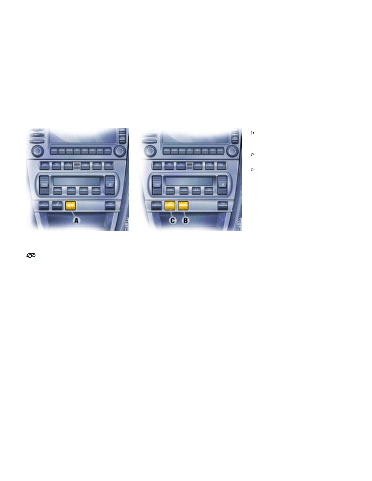
Sports Exhaust System
Sports exhaust system for
vehic les without sports mo de
The spor ts exhaust system can be switched on and
off when the ignition is switched on using button A.
When the sports exhaust system is switched on,
the light-emitting diode in the butt o n lights up.
Sports exhaust system for vehicles wit h
sports mode
The sport exhaust system can be switched on and
off when the ignition is on using the SPORT button
B.
Switching on the sports mode actuates the
markedly sporty PASM shock-absorber tuning.
However, should you wish to have a more com-
fortable shock absorbe r setting, but still use the
characteristics of the sport mode and the sport
exhaust syste m, the PASM can be switched to Nor-
mal mode separately.
To do so press the PASM b utton C. The
light-emitting diode in the PASM button goes
out.
Please observe the c hapter ”SPORT MODE” on
page 72.
Please observe the chapter ”PORSCHE
ACTIVE SUSPENSION MANAGEMENT (PASM)”
on page 76.
Controls, Instrume nts
71
Downloaded from www.ManualsFile.com manuals search engine
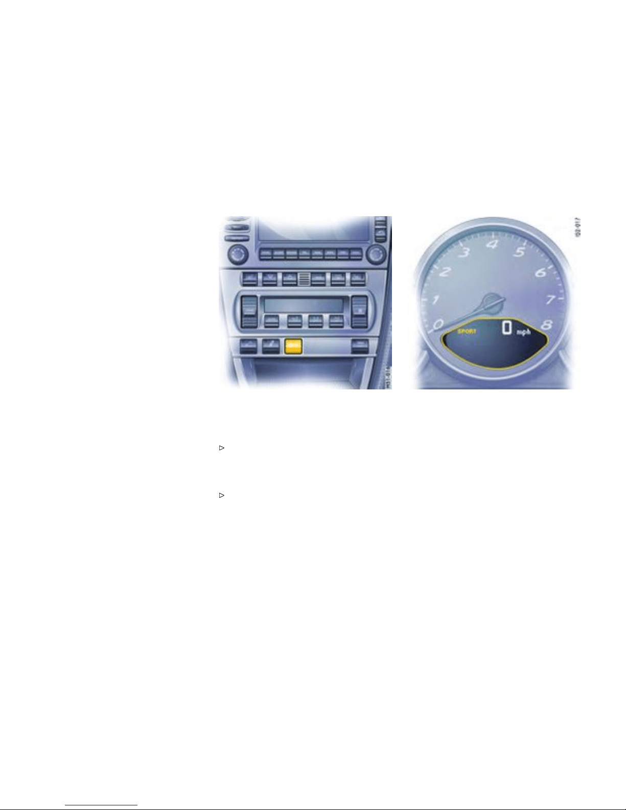
Sport M o d e
Function
A sportier car set-up is obtained when Sport mode
is switched on. Interventions by the Porsche
control systems are intentionally shifted tow ards
greater agility and driving performance.
– PASM (Porsche Active Suspension
Management) is automatical ly changed
to Sport mode, resulting in a stiffer suspens ion
setup.
– The Tiptronic S swi tches to a sporty gear-
changing map and shortens the gear shifting
periods. Gear changes take place faster.
– PSM (Porsche Stability Management) control
is sporty. PSM inter ventions are later than in
Normal mod e. The driver can maneuver the
vehicle with greater agility at its performance
limits, without havin g to dispense with the
assistan ce of PSM in emergency situations.
This helps to achieve optimal lap times,
par ticularly on race circuits with a dry road
surface.
– The electronic accelerator pedal reacts
sooner, and the engine is more responsive to
throttle inputs. When Sport mode is switched
on, this function is activated only after the
driver has briefly released the accelerator
pedal.
– The rpm limiter characteristic is “harder”, i.e.
the engine is immediately throttled when the
performance limits are reached.
Please observe the appropriate chapters PSM,
PASM and Tiptronic S.
Switching Spor t mode on and off
Press SPORT button in the center console.
When Sport mode is switched on, the light-
emitting diode in the SPORT button is lit.
When Sport mode is switched on, the logo SPORT
appears next to the digital speedometer.
Switching Sport mode on and off simultaneously
activates and deactivates the Sport mode of the
PASM.
If the Sport mode of the PASM was activated with
the PASM b utton, it will remain on.
After the ignition is switched off, Sport mode
and PASM Sport mode are automatically reset
to Normal mode.
72Controls, Instruments
Downloaded from www.ManualsFile.com manuals search engine

Porsche Stability Management
(PSM)
Gener al information regarding PSM
PSM is an active control system for stabilization of
the vehicle during extreme driving maneuvers.
Warning!
Risk of an accident, resulting in serious
person al injury or death. The increased
control that is provided should not induce
you to take greater risks with your safety. The
limits dictated by t h e laws of physics cannot
be overcome, even with PSM. The risk of
accidents due to inappropriate speed canno t
be reduced, even by PSM. The driver bears
the responsibility for all driving maneu vers.
Adapt your driving style to the prevail ing road
and weather condit ions.
Obey all traffic laws.
Advantages of PSM
– Superio r tractio n and lane- holding ability in all
driving situat ions - even on road surfaces with
varying friction.
– The system compens ates for undesired vehi-
cle reactions (Ferraria effect) when the driver
releases the accelerator pedal or brakes on
bends. This compensation functions up to the
maximum lateral acceleratio n .
– PSM actively s tabilizes the vehicle during
dynamic driving maneuvers (e.g. rapid
steerin g movements, during lane changes
or on alternating curves).
– Improved braking stability in curves and on
different or varying road surfaces.
Readiness for operation
PSM is switched on automatically every time you
start the engine.
Function
Sensors at the wheels, brakes, steering system
and engine continuously measure:
– Speed
– Direction of travel (steering angle)
– Lateral acceleration
– Rate of turn about the vert ical axis
PSM uses these values to determine the direction
of travel desired by the driver. PSM intervenes and
corrects the course if the actual direction of motion
deviates from the desired course (steering-wheel
position): It brakes individual wheels as needed. In
addition, the engine power may be manipulated in
order to st abilize the vehicle.
The events below inform the driver of PSM control
operations and warn him to adapt her/his driving
style to the road conditions:
– The multi-functional information light on the
instrument panel flashes.
– Hydraulic noises can be heard.
– The vehicle decelerates and steering-wheel
forces are altered as the PSM controls the
brakes .
– Reduce d engine power.
– The brake pedal pulsates and its position is
changed duri n g braking. In order to achieve
full vehicle deceleration, foot pressure must be
increased after beginning of the brake peda l
pulsing.
Examples of PSM control operations
– If the front wheels of the vehicle drift on a bend,
the rear wheel on the inside of the bend is
braked and the engine power is reduced if
necessary.
– If the rear of the vehicle swings out on a ben d ,
the front wheel on the outside of the bend is
braked.
Controls, Instrume nts
73
Downloaded from www.ManualsFile.com manuals search engine
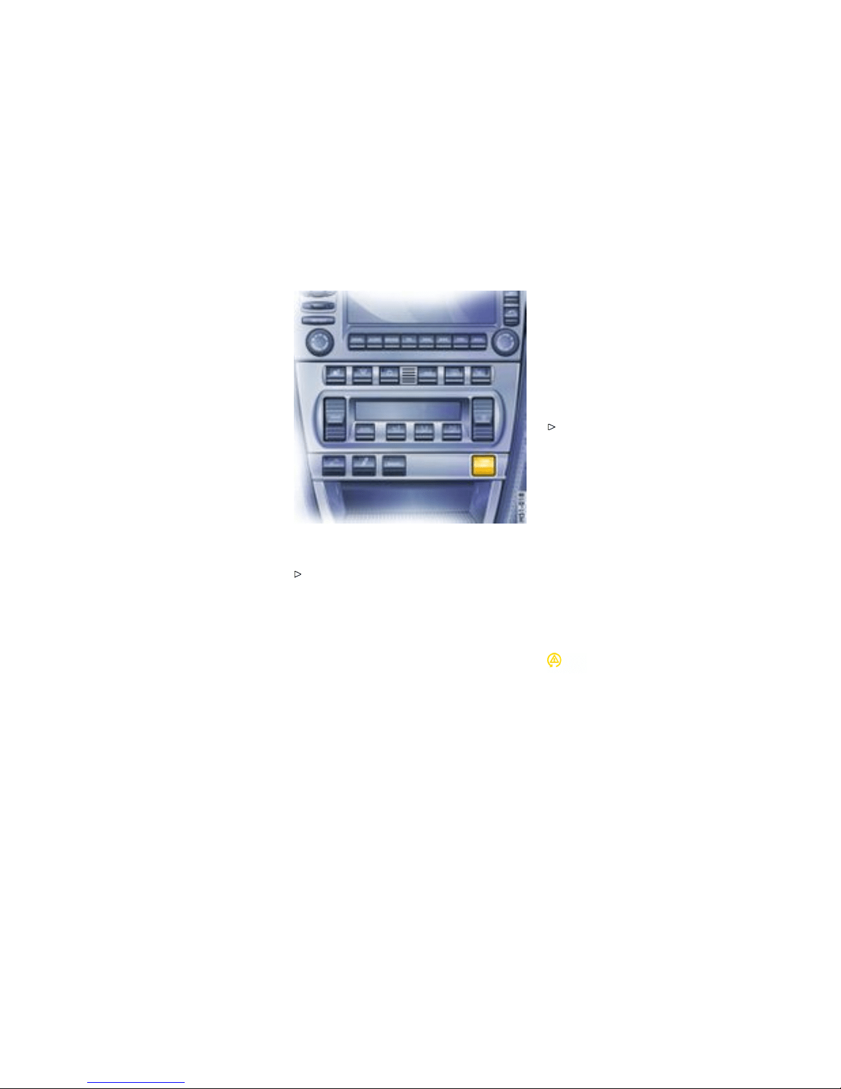
PSM sho uld always be switched o n during
“normal” driving.
However, it may be advantage o u s to switch off
PSM tempora rily in exceptional situations, for
example:
– On a loose surface or in deep snow,
– When “rocking the vehicle free”, or
– When using snow chains.
Switching off PSM
Press the PSM OFF button. PSM is switched
off after a short delay. The light-emitting diode
in the button is illuminated. When the PSM is
switched off, the multifunctional PSM light on
the instrument panel is lit and a message is
shown by the on-board computer. An acoustic
signal also sounds.
The following functions stabilize the vehicle in
emergency situations, even with PSM switched off:
– When PSM is off, the vehicle is stabilized as
soon as one of the two front wheels enters the
ABS control range.
– When PSM is off and Sport mode is on, the
vehicle is stabilized as soon as both front
wheels enter the ABS control range.
One-s i ded spinning of the wheels is reduced,
even with PSM switched off, to enable optimum
traction on all drive wheels.
Switching PSM back on
Press PSM OFF button. PSM is switched on
after a short delay. The light-emitting diode
in the button and the multifunctional PSM
light go out. The on-board comp uter shows a
message.
Sport mode
A sportier car s et-up is obtained when Sport mode
is switched on. PSM interventions are later than in
Norma l mode; the vehicle can be maneuvered with
greater agility at its performance limits, without
the need to dispense with the assistance of PSM
in emergency situations. This helps to achieve
optimal lap times, particul arly on race circuits and
a dry road surface.
Multifunctional PSM light
– The multifunctional light on the instrumen t
panel lights up for a lamp check when the
ignition is switched on.
– The light indicates a control operation by
flashing, including when PSM is switched off
74Controls, Instruments
Downloaded from www.ManualsFile.com manuals search engine

(brake control in the ev ent of one-sided wheel
spin).
– In conjunction with a message on the on-board
computer, the light indicates that PSM is
switched off. An acoustic signal also sounds.
– Faults are displayed by the light in conjunction
with a message on the on-board computer.
PSM is out of order.
Please consult an authorized Porsche dealer.
Please observe the c hapter ”PUTTIN G
VEHICLE INT O OPERATION” on page 264.
Towing
Please observe the chapter ”TOWING” on page
287.
Checks on test stands
When carrying out brake tests on roller test
stands a maximum testing speed of 5 mph
(8 km/h) must not be exceeded.
Handbrake checks on the roller brake tester
must be performed only with the ignition switched
off.
Controls, Instrume nts
75
Downloaded from www.ManualsFile.com manuals search engine
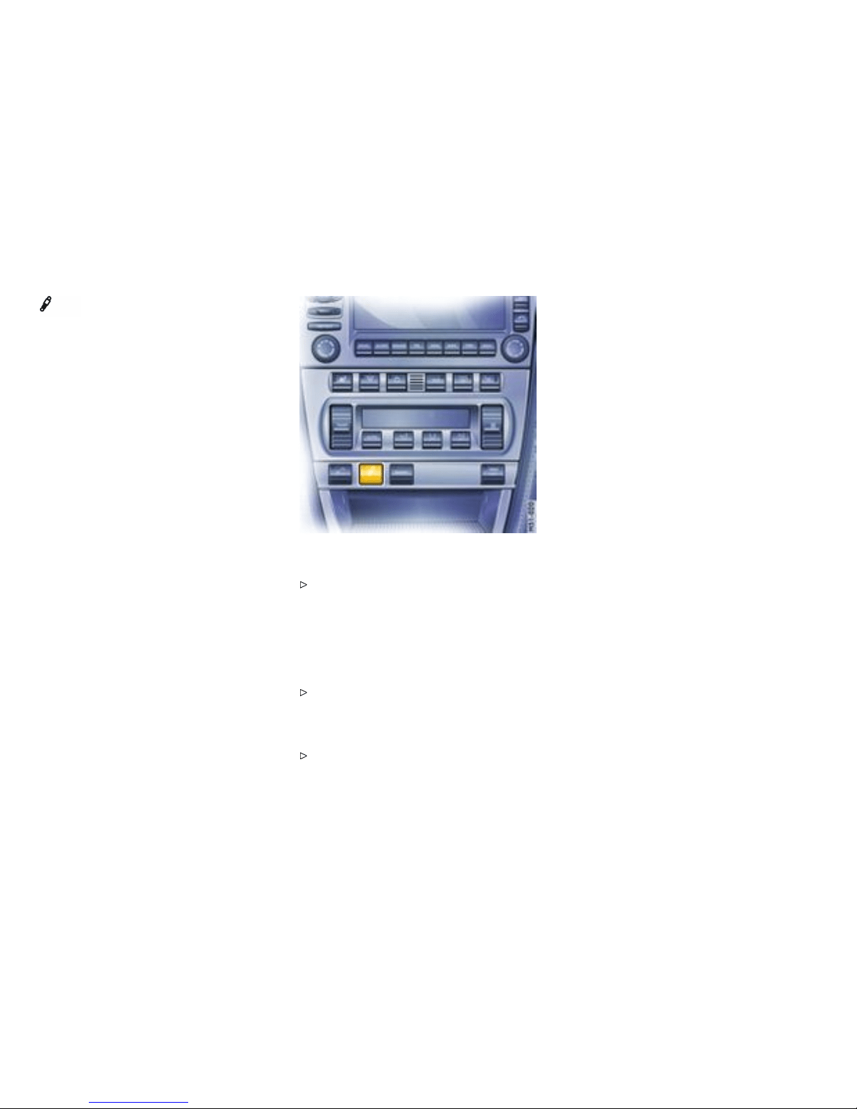
Porsche Active Suspension
Management (PA SM)
Function
PASM makes two running-gear setups availabl e to
the driver: “Normal” and “Sport”. The selection is
made via a b utton on the center console.
After the ignition is switched off, PASM is automati-
cally reset to Normal mode.
In Normal mode the running gear is in a sporty and
comfortable setup . Sport mode offers a markedly
sporty shock absorber tuning (e.g. for driving on
the race circuit).
The variable suspension system selects the appro-
priate damping level for each wheel according to
the situation and conditions of driving.
Example: If the vehicle is driven in a mark edly
sporty manner in Normal mode, PASM automat-
ically adapts the shock-absorber behavior to the
driving situati on in this case as well.
Switching on PASM Sport mode
Press PASM button in the center console.
When PASM Sport mode is switched on, the
light-emitting diode in the button is illuminated
and a message is shown by the on-board
computer.
Switching off PASM Sport mode
Press PASM button in the center console. The
light-emitting diode in the button goes out and
the on-board computer display s a messa ge for
a limited amount of time.
Please observe the chapter ”SPORTS
EXHAU ST SYSTEM” on page 71.
76Controls, Instruments
Downloaded from www.ManualsFile.com manuals search engine
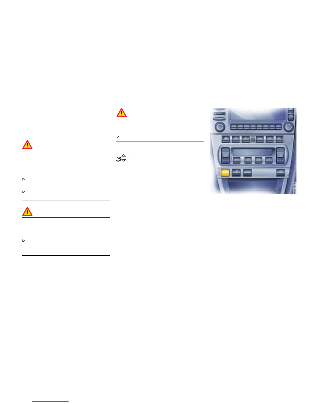
Retractable Rear Spoiler
Function
The rear spoiler improves driving stability, especial-
ly at hi gher speeds.
Warning!
Risk of accident. If the rear spoiler canno t be
extended, driving stability will be adverse ly
affected by increased rear axle lift, which
could lead to loss of control.
Adapt your driving style and speed to the
change d driving behavior.
Have the fault remed ied at an authorized
Porsche deal er.
Warning!
Risk of injury during manual retraction or
extension of the rear spoiler with the vehicle
stationary.
Make sure th at no persons or objects are
within the range of movement of the rear
spoiler.
Caution!
Risk of damage from pushing the vehicle by
the rear spoiler.
Do not push the vehicle at the rear spoiler.
Warning light
The warning light in the on-board computer lights
up when the rear spoiler does not extend over
75 mph (120 km/h) or its end positi on is not
reached.
Autom atic control
The rear spoiler extends at approx. 75 mph
(120 km/h) and retracts again at approx. 50 mph
(80 km/h).
If the automatic control fails, the warning light lights
up and the rear spoiler must be manually extend ed
before driving.
Manual control
Manual extending and retractin g
When the ignition is on, the rear spoiler can be
extended and retracted manually using the button
in the center console.
Note
When the rear spoiler is extended manually, the
automatic control does not operate and the rear
spoiler must be manually retracted.
Controls, Instrume nts
77
Downloaded from www.ManualsFile.com manuals search engine

Extending
Press button briefly. The rear spoiler extends
to its f inal position. The light-emitting diode in
the button lights up. The rear spoiler remains
extended even after switching off the ignition.
Retracting
at speeds between 0 and 20 mph
(0 and 30 km/h): Press and hold button until
the rear spoiler has reached its final position.
The light-emitting diode in the button goes out.
The rear spoiler changes to automatic mode.
at speeds between 20 and 60 mph
(30 and 100 km/h): Press button briefly.
The rear spoiler retract s, the light-emitting
diode in the b utton goes out. The rear spoiler
changes to automatic mode.
at speeds over 60 mph (100 km/h): Press
button briefly. The rear spoiler remain s
extended, the light-emitting diode in the
button goes out. Th e rear spoiler changes
to automatic mode.
Manually retracting an extended rear spoiler
after swit ching on the ig nition agai n
1. Press button briefly. Th e light-emitting diode in
the button lights up. The rear spoiler is now in
manual mode.
2. Press and hold button until the rear spoiler has
reached its final position. The light-emitting
diode in the button goes out. The rear spoiler
change s to automatic mode.
78Controls, Instruments
Downloaded from www.ManualsFile.com manuals search engine
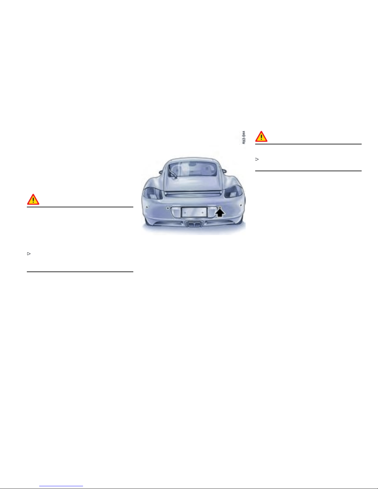
Parking Aids
Parking Assist ant (ParkAs sistant)
Function of the parking assistant
When the driver backs up, the parking assi stant
system indica tes the d istance between the c ar
and a large obstacle behind it, by means of signal
tones.
Danger!
Risk of serious personal injury or death.
ParkAssistant cannot detect small objects
such as children and pets. Despite use of the
parking assistant system, the driver is still
responsible for taking due care and assessing
obstacles when backing up.
Make sure that no persons, especially small
children, animals or obstacles are within the
maneuvering area.
The parking assistant system is activated automati-
cally when reverse gear is selected and the ignition
is on.
Note
Be aware that the parking assistant system is
not switched on if the car rolls backward without
reverse gear being engaged.
Ultrasound sensors
Sensors
Four ultrasound sensors in the rear bumper
measure the distance to the closest obstacle.
– Range middle sensors around 60 in./150 cm
– Range outer sensors around 24 in./60 cm
Obstacles cannot be detected in the “blind” sensor
area (e.g. near the ground).
Note
The sensors must always be kept free of dust,
ice and snow in order to ensure that they are fully
functional.
Caution!
To avoid damaging the senso rs:
Maintain sufficient distance when cleaning with
steam-jet units.
Signal ton es/function
When reverse gear is selected, the parking
assistant confirms that it is switched on by issuing
a short signal tone. A detect ed obstacle is
signalled by an intermittent tone. The intervals
decrease as the obstacle is approached. A
continuous tone sounds when the distance
becomes less than one foot. This continuous tone
can stop if the obstacle is approached closer than
one foot. The radio volume should not be so
loud as to d rown out the signal tones.
Limits of ultrasonic measurement
The parking assistant system cannot detect:
– sound-absorbing obstacles (e.g. wint er
operati on, powder snow),
– sound-reflecting obstacles (e.g. glass
surfaces, flat painted surfaces)
– and very thin obstacles.
Other ultrasound sources (e.g. pneumatic brakes
of other vehicles, jackhammers) can interfere with
detection of obstacles.
Controls, Instrume nts
79
Downloaded from www.ManualsFile.com manuals search engine
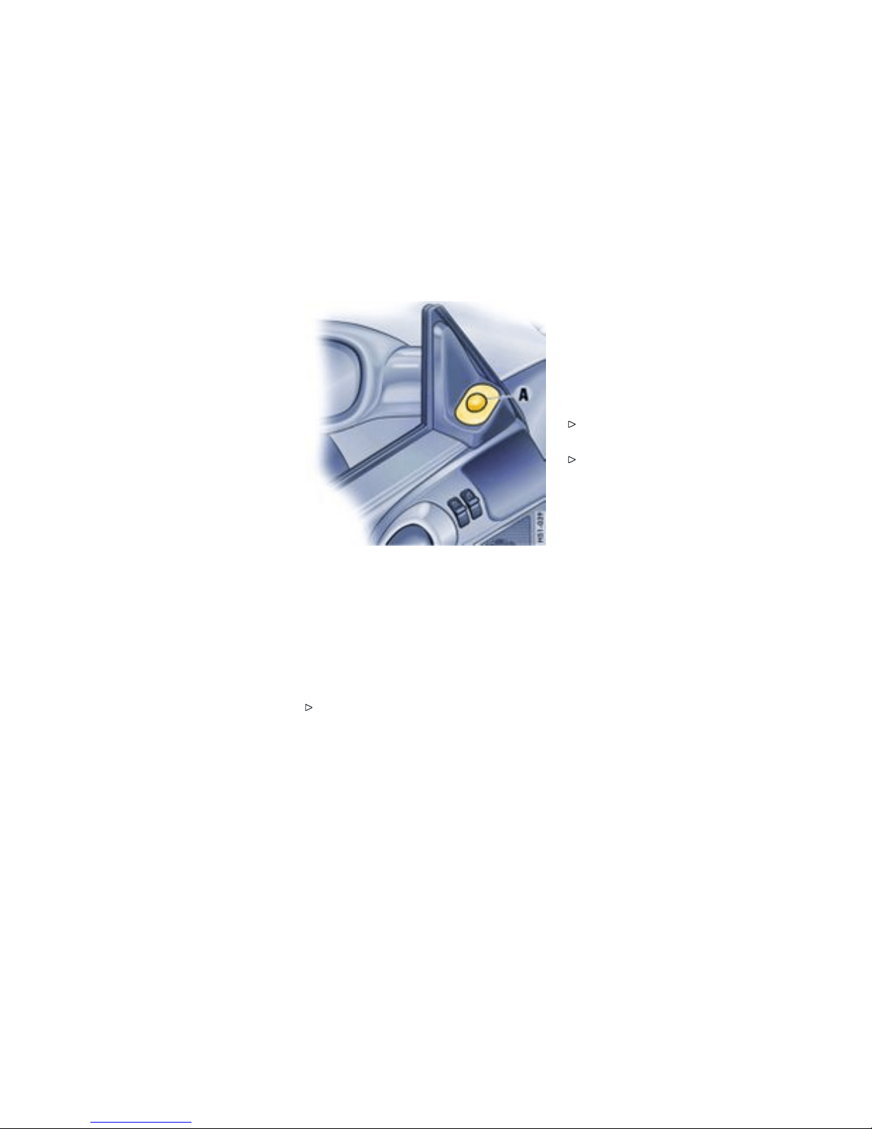
Fault indication
The parking assist ant system indicates a fault in
two ways:
– After reverse gear has b een selected, the
short signal tone is followed by a continuous
tone of the same pitch: This i ndicates that
sensors are soiled or covered w ith ice.
– After reverse gear has b een selected, the
short signal tone is followed by a continuous
tone with a much lower pitch: This indicates
a general system fault. Pl ease have the fault
remedied at an authorized Porsche dealer.
A - Control switch for door mirror adjustment
Swivelling down m irror glass on t he
passenger’s side
Function
On vehicles with seat memory you can activate an
additional parking aid.
Please observe the chapter ”SEAT MEMORY”
on page 43.
When reverse gear is engaged, the mirror glass on
the passeng er’s side swivels down slightly to show
the curb area.
Preconditions
– Vehicle must be equipped with seat memory.
– Set the control sw itch A to “passenger’s side”.
– Reverse gear must be engage d.
Returning mirror glass to its origi nal position
Drive forwards with a speed of over 4 mph
(6 km/h) or
Set the control switch A to “driver’s side”.
80Controls, Instruments
Downloaded from www.ManualsFile.com manuals search engine

A - Switch for interior, footwell, and luggage
compa rtment lights
B - Orientation light
C - Reading light
Interior Lights
Interior lights, reading ligh ts, footwell
lights, lu ggage compartment lights
Please observe the chapter ”LOAD SWITCH-
OFF AFTER 2 HOURS OR 7 DAYS” on page
259.
Switching on lights
Switch position 1.
Switch on driver’s s ide:
interior lights on driver’s side, footwell and luggage
compartment lights on.
Switch on pa ssenger’ s side:
reading light on passenger ’s side o n.
Switchin g off lights
Switch position 2.
Switch on driver’s s ide:
interior lights on driver’s side, footwell and luggage
compa rtment lights off.
Switch on pa ssenger’ s side:
reading light on passenger ’s side o ff.
Switching l ights on an d off automatically
Switch position 0.
Lights are switched on when a door or rear lid
is unlocked or opened or when the ignition key is
withdr awn from the ignition lock.
The lights are switched off with a del a y of
approx. 2 minute s after the door is closed. The
lights go out immediately as soon as the ignition
key is inserted in the ignitio n lock or the vehicle is
locked.
Orient ation light
The light-emitting diode in the interior light
improves your orientation inside the vehicle when it
is dark.
Note
On vehicles with Sport Chrono Package Plus, the
brightness of the orientation light can be changed
in PCM.
Please observe the chapter ”Individual
Memory“ in the separate PCM operating
instructions.
Controls, Instrume nts
81
Downloaded from www.ManualsFile.com manuals search engine
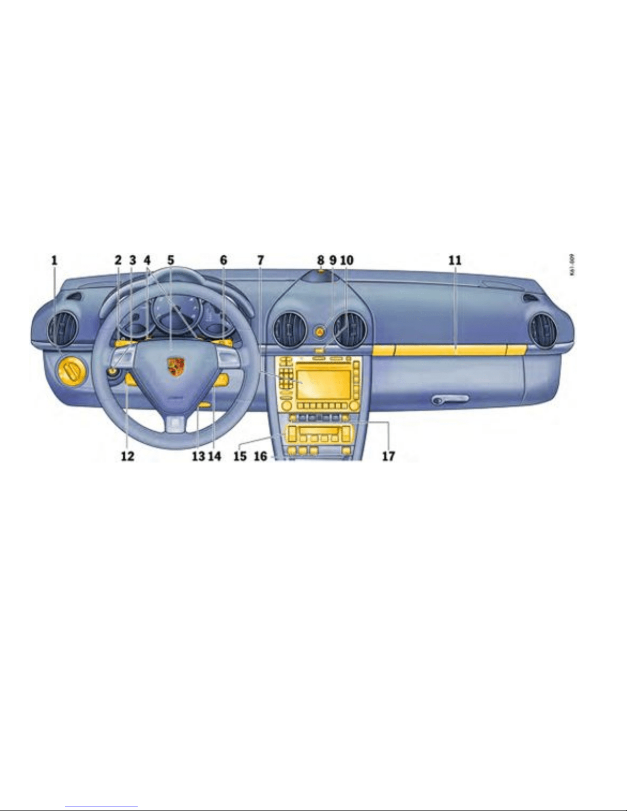
Operation, Instrumen ts
Overview of t he functions
1 Light switch
2 Turn signals/ headlight dimmer/asher
lever
3 Ignition lock/ locking the steering column
4 Hands- f ree microphone for telephone
5 Horn
6 Windshield wiper/washer lever, Rear
window wipe r
7 Porsche Com munication
Management/Radio
8 Interio
r temperature sensor, GPS antenna
9 Emergency asher switch
10 Central locking button, Readiness display
for alarm syste
m
11 Cupho lder
12 Operating lever for on-board computer
13 Locking lever f or st
eering- wheel adjustmen t
14 Operating lever for cruise control
15 Control panel for heating, ventilation and air
conditi
oning system
16 Buttons for rear spoiler, Porsche Active
Suspension Management PASM), Sport
Mode, Porsche S
tability Management
(PSM), Sports exhaust system
17 Seat hea ting, left/right
82Controls, Instruments
Downloaded from www.ManualsFile.com manuals search engine
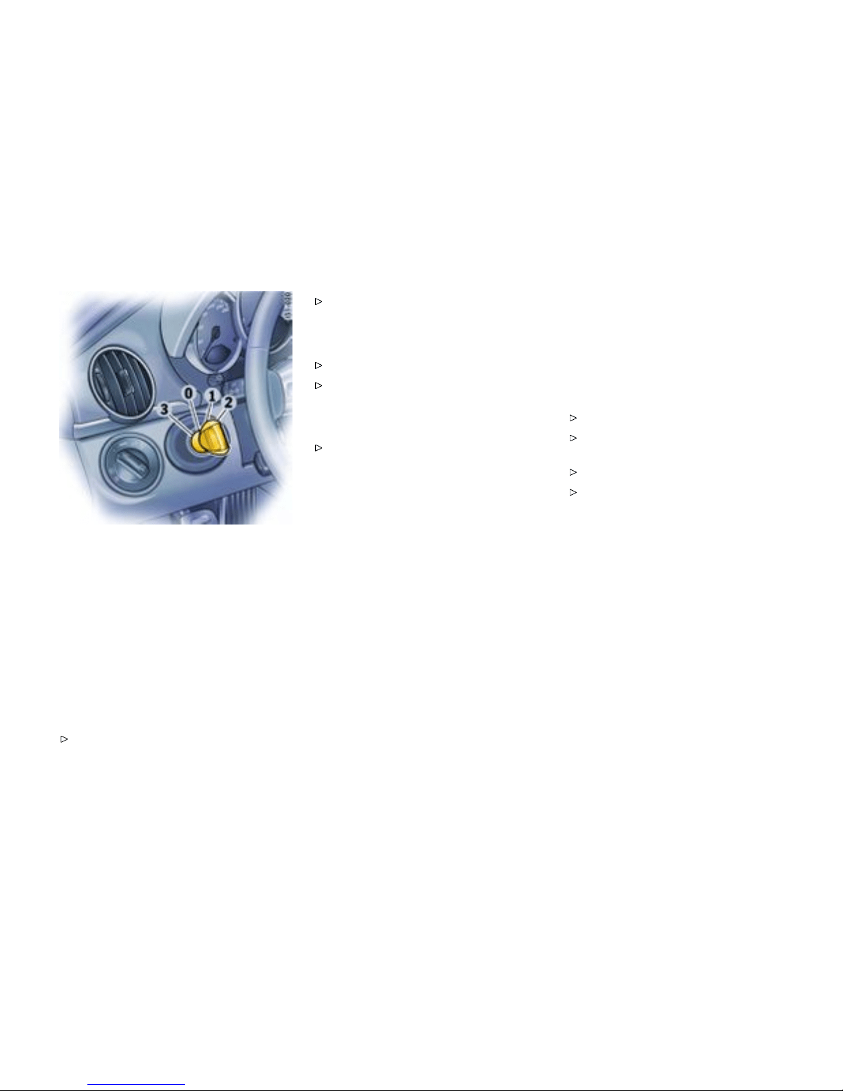
0 - Initial position
1 - Ignit ion on
2 - Start engine
3 - Ignit ion off
Ignition/Starter Swi tch with
anti-theft Steering Lock
The ignition lock has a total of four ignition lock
positions. The ignition key rebounds to the initial
position from every ignition lock position.
For your safety, fasten safety belts.
Please observe the ch apter ”IMMOBILIZER” on
page 22.
Please observe the chapter ”KEY WITH RADIO
REMOTE CONTROL” on page 23.
Before starting the engine
Apply the footbrake.
Manual tran smission: Move the gearshift
lever into neutral. The clutch pedal must
be depressed fully before the starter will
engage.
Tiptronic: Mo ve the selector lever to P or N.
Switch p osition 0
Initial position
The ignition key cannot be withdrawn when the
ignition is switched on or when the engine has been
started.
To withdraw the ignition key:
Stop the vehicle.
On vehicles with Tiptronic S: Move selector
lever to position P.
Switch igniti on off.
Remove ignit ion key.
Controls, Instrume nts
83
Downloaded from www.ManualsFile.com manuals search engine

Switch position 1
Ignition on
Turn ignition key to p osition 1. Ignition is
switched on.
Note on operation
All electrical equipment can be switched on.
Please obse rve the chapter ”WARNIN GS
ON THE INSTRUMENT PANEL AND THE
ON-BOARD COMPUTER” on page 138.
Switch position 2
Start eng ine
Turn ignition key to ignition lock position 2.
Please observe the chapter ”STARTING AND
STOPP ING ENGINE” on page 86.
Switch p osition 3
Ignition of f
Turn ignition key to i gnition lock position 3.
84Controls, Instruments
Downloaded from www.ManualsFile.com manuals search engine

Locking the steering column
Automatic locking
The steering column is automatically locked when
the ignition key is withdrawn from the ignition lock.
Warning!
Risk of an accident, resulting in serious
personal injury or death. The steering wheel
will lock and will cause loss of s teering.
Never remove key from the ignition lock or turn
the key off while the vehicle is moving.
Always withdraw the ignition key when
leaving the vehicle.
Automatic unlocking
The steering column is automatically unlocked
when the ignition key is in serted into the ignition
lock.
Note
To avoid battery run-down, always remove the
ignition key from the ignition lock.
Please observe the chapter ”LOAD SWITCH-
OFF AFTER 2 HOURS OR 7 DAYS” on page
259.
Gong
If you leave the key in the ignition/steerin g lock, a
gong will sound when the driver’s door is opened.
This is a reminde r to remove the key.
Controls, Instrume nts
85
Downloaded from www.ManualsFile.com manuals search engine

Starting and Stopping Engine
Starting Proce dures
Please observe the chapter ”IMMO BILIZER” on
page 22.
Please observe the chapter ”EMISSION
CONTROL SYSTEM” on page 220.
Warning!
Serious personal injury or death may result if
you are inv olved in a collision without hav ing
fastened the safety belts.
Fasten safety belts before driving away.
Before st arting the engine
Apply the footbrake.
Manual tran smission: Move the gearshift
lever into neutral. The clutch pedal must
be depressed fully before the starter will
engage.
Tiptronic: Move the selector lever to P or N.
Temperature sensors on the e n gine automatically
provide the correct fuel/air mixtu re required
for starting. Therefore, it is not necessary to
depress the accelerator pedal while startin g a
cold or a warm eng ine.
Starti ng the engine
Turn ignition key to ignition lock position 2.
As soon as the e n gine starts, release the
ignition key.
The first operation of the starter is ended automat-
ically when the engine starts. If the engine does
not start, subsequent starter operations will not be
ended automatically.
If the engine fails to start after 10 or 15 seconds of
cranki n g:
Wait about 10 seconds before engaging the
starter again.
When starting the engine, be ready to drive
immediately. Driv e vehicl e at moderate
speeds and avoid engine speeds above
4200 rpm during the first 5 m inutes.
Do not let the engine idle to warm up.
Danger!
Engine exhaust fumes have many compo-
nents which you can smell. They also contain
carbon monoxide (CO), which is a c olorless
and odorless gas. Carbo n mon oxide can
cause unconsciousn ess and even death if
inhaled.
Never start or let the engine run in an
enclosed, unventilated area. It is not rec-
ommended to sit in your car for prolonged
periods with the engine on and the car not
moving.
Danger!
An unattended vehicle with a running engine
is potentially haz ardous. If warning lights
should com e on to indicat e improper opera-
tion, they would go unnoticed.
Never leave the engine idling unattend ed.
Danger!
Dange r of re.
Do not park or operate the vehicle in a reas
where the hot exhaust system may come in
contact with dry grass, brush, fuel spill or
other flammable material.
86Controls, Instruments
Downloaded from www.ManualsFile.com manuals search engine
If your car c atches on fire for any reason, call
the fire department. Do not endanger your life
by attempting to put out the fire.
Stopping engine
Turn key back to position 3.
Do not stop engine immediate ly after hard
or extended driving. Keep engine runnin g
at increased idle for about two minutes to
prevent excessive heat build-up before turning
off engine.
To avoid battery run-down, always remove the
ignition key from the ignition lock.
Make sure that when you leave the car, ev en
briefly, you have withdraw n the ignition key.
Engag e the steering lock by moving the
steerin g whe el to the left or right. Turn
the steering wheel to the locking position
before you switch off the engine so that you
don’t have to exert yourself when locking or
unlocking the steering.
Warning!
Danger of injury. Ho t engine compar tment
comp onents can burn skin on contact.
Before working on any part in the engine
compartment, turn the engine off and let it
cool down sufficiently.
Engin e-compa rtment blower, radiator fan
The radiator and radiator fans are in the front of the
car. The engine-compartm ent blower is mounted in
the engine compa rtment.
Warning!
Risk of injury. After the engine is switched
of f, the engine-compar t ment tempera tures
is monitored for approx. 30 minutes. Du ring
this period, and depending on temperature,
the engine-compartm ent blower may contin-
ue to run or start to run.
Carry out work in these areas only with the
engine off and exercise extreme caution.
Warning!
Risk of injury. The radiator fans in the front
end of the car may be operating or unex-
pectedly start operating when the engine is
switc hed on.
Carry out work in these areas only with the
engine switched off.
Automatic garage door
The ignition system in your Porsche may interfere
with your electronically operated garage door.
To check this, drive your Porsche close to the
garage door. Make sure not to interfere with
the operating rang e of the door.
Run the engine at different speeds.
If the garage door opens or closes without you
operating the garage door unit in your car, contact
the dealer who installed the automa tic garage door
to have the frequency and/or coding of the garage
door signal changed or modified.
Controls, Instrume nts
87
Downloaded from www.ManualsFile.com manuals search engine

Instrument Panel USA Models
Overview
Also refer to the corresponding chapte r in the
Owner’s Manu al.
1. Speedometer with analogue display
2. Tire pressure warning light
3. Turn signal indicator light left
4. Tachometer
5. High beam indicator light
6. Turn signal indicator light right
7. ABS warning light
8. Cooling system Temperature gauge, warning
light
9. Fuel Level gauge, warning light
10. Adjusting button for instrument illumination
and trip counter
11. Odometer and daily trip mileage display
12. Automatic speed control indicator light
13. Light sensor for instrument illumination
14. Airbag warning light
15. Emission control warning light (Check Engine)
16. Ce ntral warning light
17. On-board computer display
18. Porsche Stability Management, Multifunctional
PSM light
19. Brake warning light
20. Safety belt warning light
21. Tiptronic indicator
22. Clock and outside temperature disp lay
23. Adjustment button for clock
When the ignition is switched on, the warning
lights light up for a lamp check.
Note
Warnings that have been given are stored in the
appropriate control unit memory and can be read
out at an authorized Porsche dealer.
This informat ion can help to warn you about
situations which may be hazardous to you or your
car.
Note
Warnings that have been given are stored in the
appropriate control unit memory and can be read
out at an authorized Porsche dealer.
This informat ion can help to warn you about
situations which may be hazardous to you or your
car.
88Controls, Instruments
Downloaded from www.ManualsFile.com manuals search engine
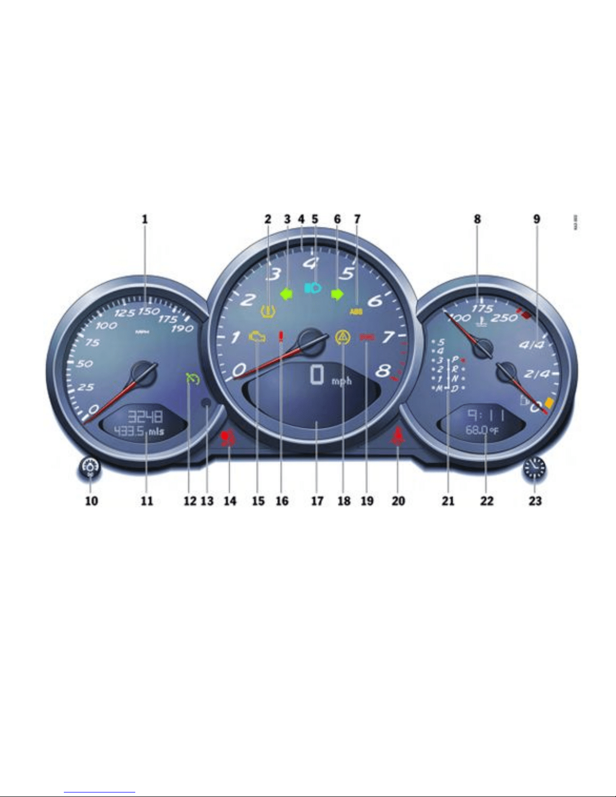

Instrument Panel Canada Models
Overview
Also refer to the corresponding chapte r in the
Owner’s Manu al.
1. Speedometer with analogue display
2. Tire pressure warning light
3. Turn signal indicator light left
4. Tachometer
5. High beam indicator light
6. Turn signal indicator light right
7. ABS warning light
8. Cooling system Temperature gauge, warning
light
9. Fuel Level gauge, warning light
10. Adjusting button for instrument illumination
and trip counter
11. Odometer and daily trip mileage display
12. Automatic speed control indicator light
13. Light sensor for instrument illumination
14. Airbag warning light
15. Emission control warning light (Check Engine)
16. Ce ntral warning light
17. On-board computer display
18. Porsche Stability Management, Multifunctional
PSM light
19. Brake warning light
20. Safety belt warning light
21. Tiptronic indicator
22. Clock and outside temperature disp lay
23. Adjustment button for clock
When the ignition is switched on, the warning
lights light up for a lamp check.
Note
Warnings that have been given are stored in the
appropriate control unit memory and can be read
out at an authorized Porsche dealer.
This informat ion can help to warn you about
situations which may be hazardous to you or your
car.
Note
Warnings that have been given are stored in the
appropriate control unit memory and can be read
out at an authorized Porsche dealer.
This informat ion can help to warn you about
situations which may be hazardous to you or your
car.
90Controls, Instruments
Downloaded from www.ManualsFile.com manuals search engine

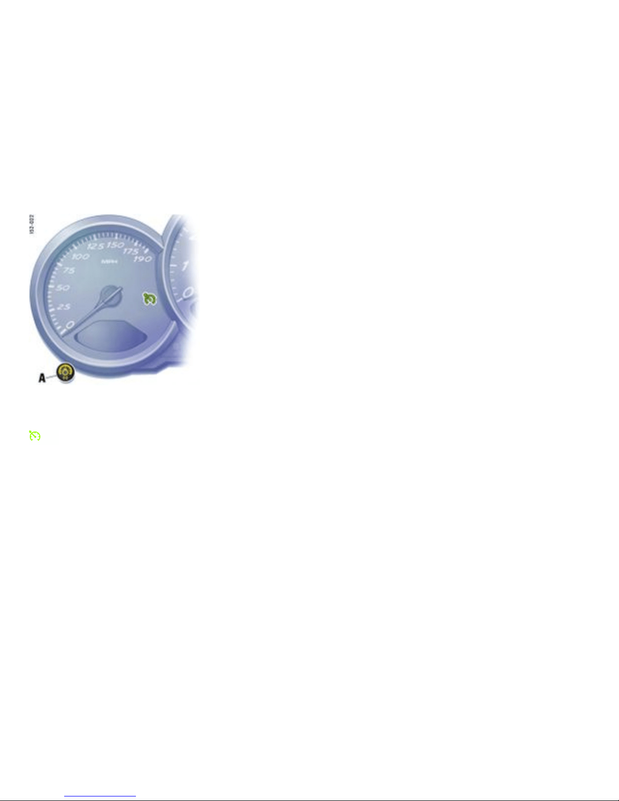
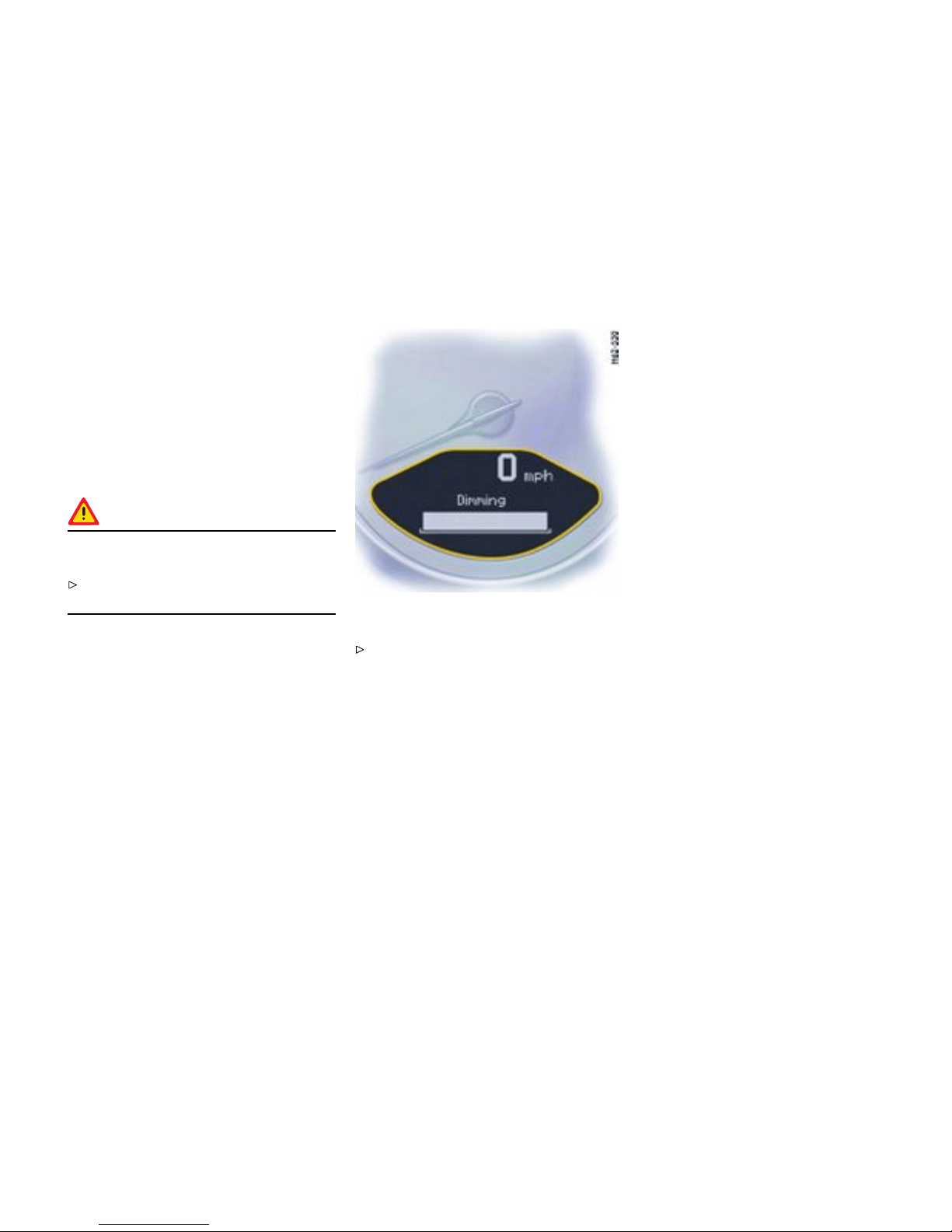
Instrumen t Illumina tion
Function
The illumination is automatically adjusted to the
ambien t brightness by the li ght sensor in the
tachom eter.
In addition, when the car lights are switched on, the
instrument and switch symbol brightnes s can be
manually adjusted.
Warning!
Risk of loss of control or an accident, resu lting
in personal injury or death.
Do not reach through the steering-wheel
spokes while drivin g.
Dimming instrument illuminatio n
Turn adjustment button A in the appropriate
direction and hold it unti l the desired bright-
ness has been reached. The chosen level of
brightness is indicated by a bar display in th e
display field of the on-board computer.
Note
When the vehicle lights are switched on, the
scale lighting for bright dials is switched on
and off automatically depending on the ambient
brightness.
Controls, Instrume nts
93
Downloaded from www.ManualsFile.com manuals search engine

Trip Odometer
Resett ing to zero
Warning!
Risk of loss of control or accident, resulting in
serious personal injury or death.
Do not reach through the steering-wheel
spokes while driving.
Press adjustment button A for approximately
one second or
Reset the distance in the “SET” menu of t he
on-boa rd computer.
Please observe the chapter ”SET BASIC
SETTING ON ON-BOARD COMPUTER” on page
134.
After exceeding 6213 miles or 9999 kilometers,
the counter returns to “ 0”.
94Controls, Instruments
Downloaded from www.ManualsFile.com manuals search engine
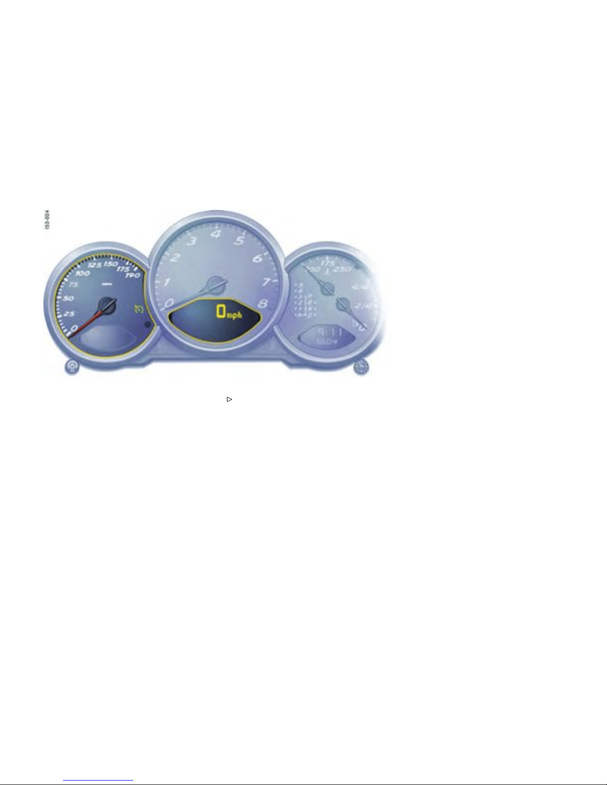
Speedometer
Indication
The digital speedometer is integrated in the
on-board computer. The indication changes from
mph to km/h when the units are changed from
miles to kilometers.
Changing over betwe en Miles / Kilometers
The units of the d istance and speed displays can
be changed in the “SET” menu of the on-board
computer.
Please obse rve the chapter ”SET BASIC
SETTING ON ON-BOARD COMPUTER” on page
134.
Controls, Instrume nts
95
Downloaded from www.ManualsFile.com manuals search engine

Tachometer
Indication
The tachometer shows the engine speed in
revolutions per minute (rpm). T he beginning of
the red marks at the right end of the scale indicates
the maximum permissible engine rpm. A speed
limiter prevents the engine from being overrevved
during acceleration. Before reachin g this area, the
next higher gear should be selected. Shift to the
next lower gear when the engine rpm drops below
1500 rpm.
Caution!
To avoid severe engine damage .
Always observe the engine rpm before
down-shifting to a lower gear, so you do not
exceed the maximum engine rpm.
Turn Signal Indicator Light
Indication
Flashes in synchronism with the turn signals.
Left arrow - left turn signals
Right arrow - right turn signals
If the frequency of the display becomes
notice ably faster, check the operation of the
turn signals.
High Bea m
Indicator light
Lights when high beam or headlight flasher is
switched on. The indicator light goes out when the
high beams are s witched off.
96Controls, Instruments
Downloaded from www.ManualsFile.com manuals search engine
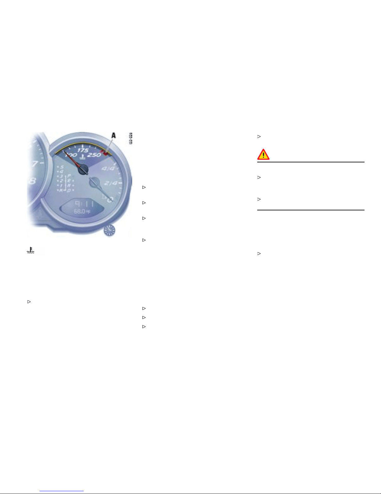
Cooling system
Temperature gauge (igniti on on)
USA: Display in F
Canada : Display in C
Pointe r to the left - engine cold
Avoid high engine speeds and heavy engine
loading.
Pointer in the middle - normal operating temper-
ature
The pointer may move up to the red area when
engine is heavily loaded and outside temperature
is high, but should return to “normal” when engine
load is reduced.
Warning light “A”
If the coolant temperature is too high, the
warning ligh t comes on. Additionally, a warning
is displayed in the on-board computer.
Pull off the road, turn off the engine and allow
to cool.
Check radiator and air pass ages in front end of
car for obstructions.
Check coolant level. If necessary, add coolant
and have fault remedied at an authorized
Porsche dealer.
Please observe the chapter ”COOLANT
LEVEL” on page 205.
Note
To prevent excessiv e temperatures, the cooling-ai r
passages must not be restricted by coverings (e.g.
films, “stone guards”).
If the coolant level is too low, the warning light
ashes. Additionally, a warning is displayed in the
on-boa rd computer.
Switch engin e of f and allow to cool.
Add coolant.
Have the cause of the fault remedied at an
authorized Pors che dealer.
Please observe the chapter ”COOLANT
LEVEL” on page 205.
Caution!
Risk of engine damage.
If the warning lights come on even though
coolant level is correct, do not continue
driving .
Have the fault remedied at the nearest
authorized Porsche dealer.
Engine compartment blower fan
In addition, this warning light ashes to indicate a
fault in the e ngine compartment blower fan.
Have the cause of the fault remedied at an
authorized Porsche dealer.
Controls, Instrume nts
97
Downloaded from www.ManualsFile.com manuals search engine

Tiptronic S
Indicat or for selector lever posi tion and
engag ed gear
When the engine is running, the selector lever
position and engaged gear are indicated.
If the sele ctor lever is between two
positions:
– The corresponding selector lever position in
the instrume n t cluster flashes and
– The warning “Selector lever not engaged”
appears on the display of the on-board
computer.
Engage the selector lever correctly.
If there is a fault in the trans mission:
– The display for 4th gear and the e ngaged
select or lever position flash on and off
altern ately.
– The warning “Tiptronic emergency run”
appears on the on-board computer.
Please observ e the chapt er ”EMERGENCY
PROGRAM” on page 199.
Have the fault repaired immediately at an
authorized Porsche dealer.
Please observe the chapter ”TIPTRONIC S” on
page 195.
98Controls, Instruments
Downloaded from www.ManualsFile.com manuals search engine
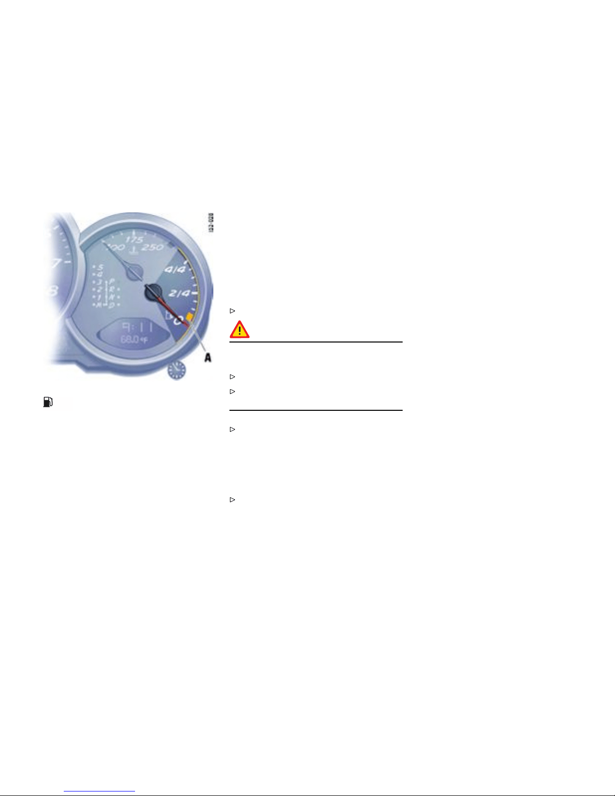
Fuel
Level gauge
When the ignition is on th e fuel level is displayed.
Refill volume approx. 16.9 U.S.gallons (64 liters).
If the v ehicle’s inclination changes (e.g. going up
or downhill), minor deviations in the indication may
occur.
Note
If a sm all quantity of fuel is added to a nearly empty
fuel tank, the fuel gauge cannot measure the added
fuel accurately. The ”remaining range“ readout will
also be incorrect.
Warning light “A”
When the engine is running, the warning light
of the level gauge lights up if less than approx.
2.6 U.S.gallons (10 liters) of fuel remains in the
tank or the range on remain ing fuel falls below
approx. 30 miles (50 km). Ad ditionally, a warning is
displayed in t he on-board computer and the central
warning ligh t lights up.
Fill up at the next opportunity.
Caution!
To prevent damage to the emission control
system and engine.
Never drive the tank completely out of fuel.
Avoid high cornering speeds after t he warning
lights have come on.
Please obse rve the chapter ”EMISSION
CONTROL SYSTEM” on page 220.
If the level gauge warning light ashes, there
has been a system fault. Additionally, a warn ing is
displa yed in t he on-board computer. There will then
be no reserve warning.
To remedy the fault, go to an authorized
Porsche dealer.
Controls, Instrume nts
99
Downloaded from www.ManualsFile.com manuals search engine

A - Adjustment button for clock
B - Clock
C - Outside temperature display
Clock
Automatic switching off
The clock is blanked out approximately four
minutes after the ignition is switched off or when
the car is locked.
Setting the time
Conditi on
Warning!
Risk of loss of control or accident, resulting in
serio us personal injury or death.
Do not reach through the steering-wheel
spokes while driving.
Setting hours
Press adjustment button A for about one
second. Hour display flashes.
Turn button in the appropriate direction:
to right - inc rease hours figure
to left - decrease hours figure.
Adjustment in hours - turn button briefly.
Fast adjustment (display cycles) - turn and hold
button.
Setting minutes
Press adjustment button again. Minutes
display flashes.
Set by rotating as in hours mode.
Leaving adjustment mode
Automatically after one minute or:
Press adjustment button again.
When adjustm ent mode is deliberately left by
pressing the button, the time begins precisely
to the second.
Note
The time mode can be changed between 12 h and
24 h in the on-board comp uter.
Outside temperature
The outside temperature display C does not
indicate, if ice is on the road. Even if a temperature
above 32°F (0°C ) is displayed, ice may still form
on the road, for instance on bridges or when the
road passes through a heavily shaded area.
100Controls, Instruments
Downloaded from www.ManualsFile.com manuals search engine
Battery
Dropping battery voltage
If the battery voltage drops abruptly, a warning
message will be displayed by the on-board
computer.
If the warning is displaye d by the on-board
compu ter while the engine is running or while
driving:
Stop the car in a safe place and stop the
engine.
Possible causes
– Defect in the battery charging system.
– Broken drive belt.
Warning!
Risk of engine damage with resultant loss
of control and accident, leading to serious
personal injury or de ath. A broken drive belt
means there is no power assistanc e to the
steering (more effort is required to steer) and
coolant pump f unction will stop.
Do not continue driving.
Have the fault remed ied at the nearest
authorized Porsche dealer.
Controls, Instruments 101
Downloaded from www.ManualsFile.com manuals search engine

Check Engine Warning Light
The warning light in the i nstrument panel comes on
when the ignition is first turned on and remai ns on
briefly as a bulb check. If the light does not come
on, have the bulb replaced promptl y.
If the warning lights in the instrument panel and
on-board computer come on and remain on while
driving, it suggests:
– a potential engine control problem and the
need for system service or
– an improperly fastened tank cap or
– refueling with engine running.
Please obse rve the chapter ”WARNIN GS
ON THE INSTRUMENT PANEL AND THE
ON-BOARD COMPUTER” on page 138.
Although the vehicl e is usually driveable and will not
require towing, see your dealer for service as soon
as possible.
Caution!
If the Check engine light in the instrument
panel is ashing, severe catalytic converter
damag e and power loss will soon occur.
Prolonged driving with the Check engine
light on could cause damage to the emission
control system. It also could affect fuel
economy and driveability.
Have the fault remedi ed at th e nearest
authorized Porsche dealer immediately.
102Controls, Instruments
Downloaded from www.ManualsFile.com manuals search engine

Central Warning Light
Warning messages in the INFO menu
The central warning light on the instrument panel
lights up if there are warning messages in th e INFO
menu.
The messages can be called in the on-board
computer INFO menu:
Please obse rve the chapter ”INFO WARNING
MESSAGES” on page 111.
Controls, Instruments
103
Downloaded from www.ManualsFile.com manuals search engine

Brake Warning Li ght
Indication
Brake warning light USA
Brake warning light Canada
The warning light on the instrument panel li ghts up:
– if the h andbrake is on,
– if the b rake fluid level is low,
– if the brake pads have reached the wear limit,
– if the b rake circuit division is defective.
Additionally, a warning is displayed by the on-board
computer.
Please obse rve the chapter ”WARNIN GS
ON THE INSTRUMENT PANEL AND THE
ON-BOARD COMPUTER” on page 138.
104Controls, Instruments
Downloaded from www.ManualsFile.com manuals search engine

On-Board Computer (BC)
Display eld
The display field is beneath the tachometer.
Readiness for oper ation
– With ignition switched on,
– with engine running .
Operation, cont rols
It is not possible to describe all details of the
on-board computer functions in this Owner’s
Manua l. However, the examples will quickly
familiarize you with the operational principle and
help you to navigate through the menu structure.
You can resto re the factory default setting s at any
time by using the “SET” menu.
Operating lever
Operation
The on-board computer is operated with the lower
left lever on the steering column.
Selectin g functions of the on-board comput er
Push lever up 3 or down 4.
Conrmin g selection (Enter)
Push the lever forward 1.
Moving ba c k one or several selection levels
Pull the lever back 2 onc e or several times or
Select the arrow on the on-board
compu ter display with the operating lever and
push the operating lever forwa rd 1.
Note
You can always return to the basic menu by pul l i ng
the operating lever several times.
Controls, Instruments
105
Downloaded from www.ManualsFile.com manuals search engine

A - Digital speedometer
B - Central display
C - Bottom display
Functions and dis play possibilities
Options
Note
The available items and displays in the on-board
computer depend on the equipment o f your
vehicle. For this reason it is possible that some of
the items and displays shown here are not available
in your on-board computer.
Basic setting
– Central display: .... Radio station
The central line B of the on-board computer can be
selecte d in the SET menu.
Calling on-board computer functions in display
“C”
Push operatin g lever up or down (selection
field D must be switched off).
The following displays can be called step by step:
– Average speed (ø mph),
– Average consumption (ø mpg),
– Range on remaining fuel (mls
).
– Tire pressure
– Naviga tion information (if activated in the SET
menu).
Note
The values “Average speed”, “Average consump-
tion” and “Daily trip mileage” can be reset to zero in
the SET menu.
Switching selection e ld “D” on or off
Push operating lever forward or back.
Arrow symbol “E” for continuation
Arrow symbol
Push operating lever down in order to page
through the menu.
Arrow symbol
Push operating lever up in order to page
through the menu.
106Controls, Instruments
Downloaded from www.ManualsFile.com manuals search engine
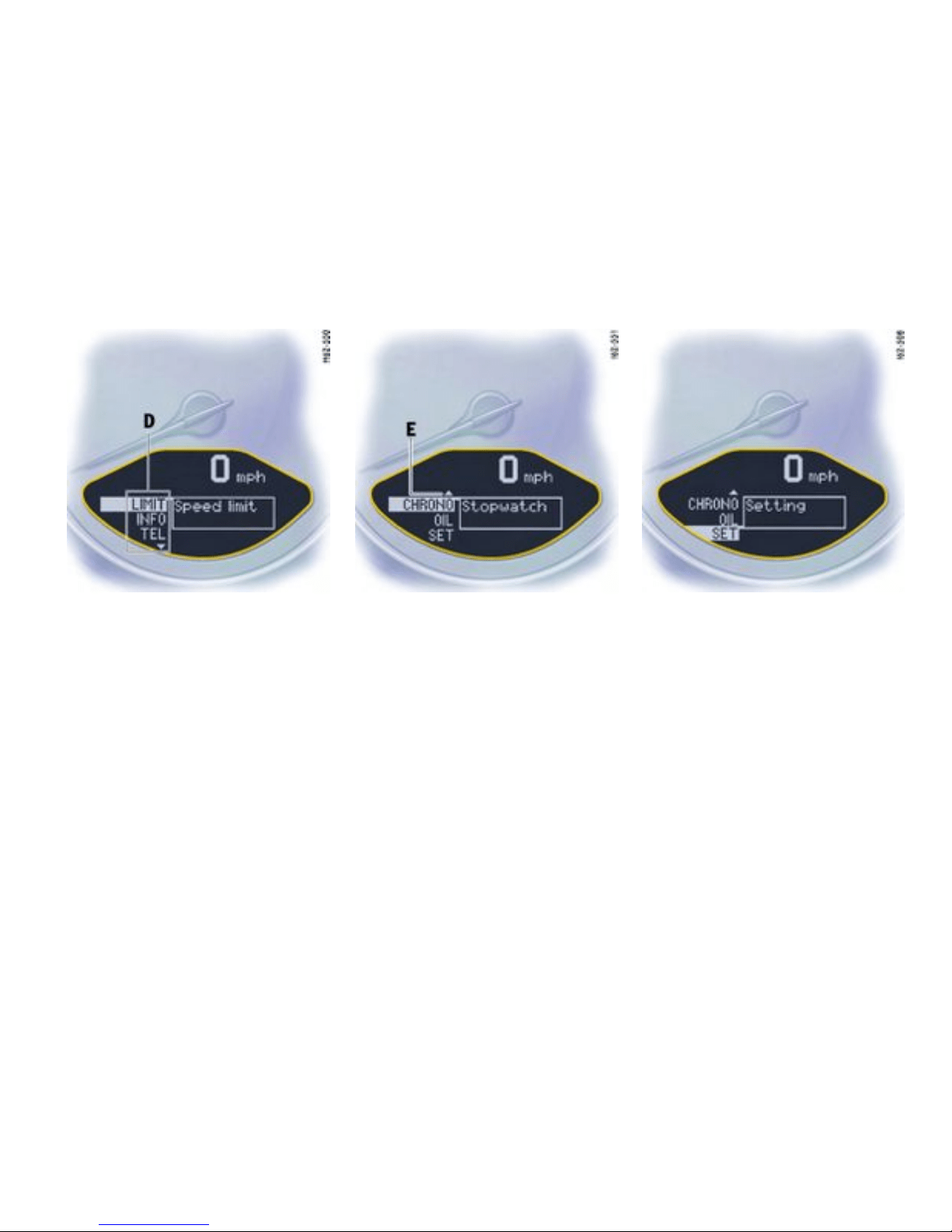
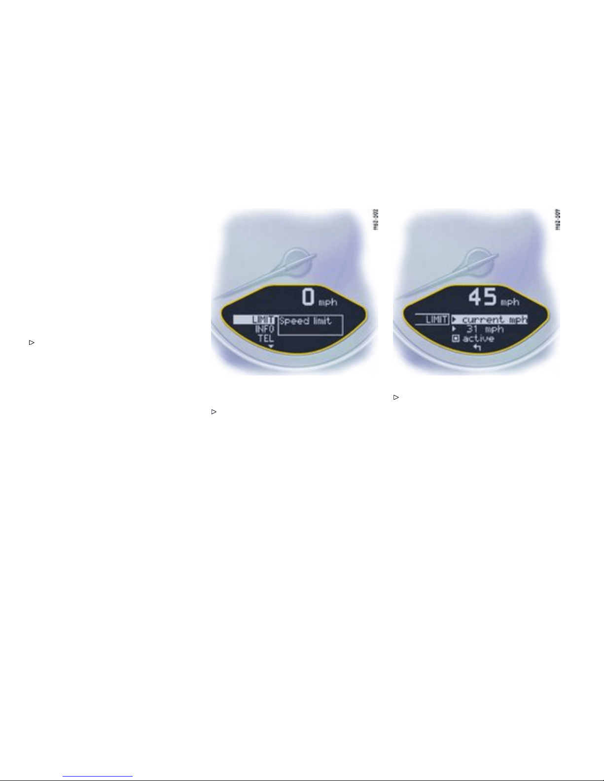
LIMIT Acoustic warning s ignal for
speed limit
Function
The acoustic warning signal can be activated for
speeds above 6 mph (10 km/h). The signal sounds
when the preset speed is exceeded. For the signal
to sound again, the driving speed must fall below
the preset speed by at least 3 mp h (5 km/h).
Switching on selec tion eld “D”
Push operating leve r forwa rd.
Settin g the spee d
Select LIMIT with the operating lever.
Push operating lever forward.
108Controls, Instruments
Downloaded from www.ManualsFile.com manuals search engine
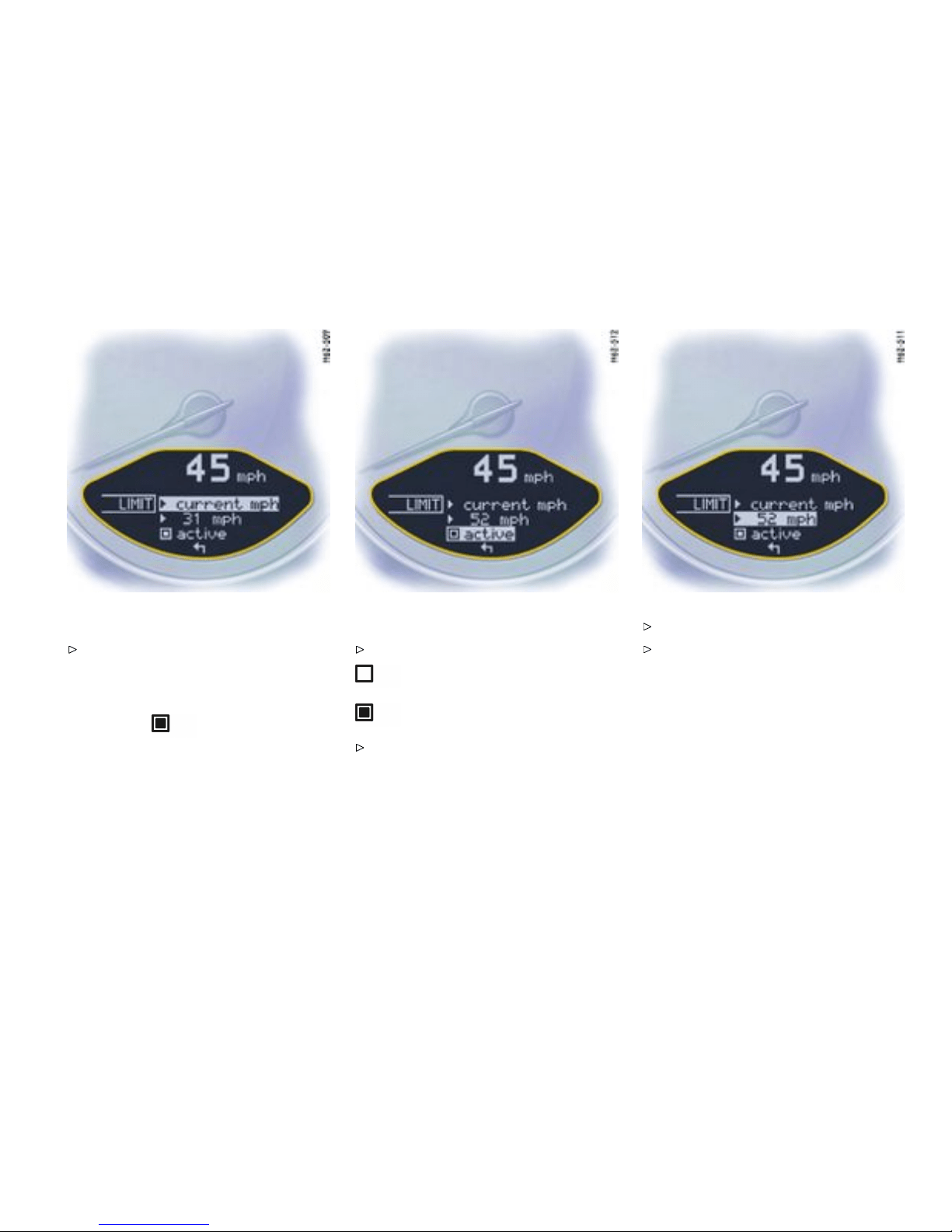
Option 1: Accepting current speed
Push operating lever forward.
The acoustic warning signal is activated for the
current speed.
Display:
Option 2: Presetting speed
Select “LIMIT active” with the operating lever:
not active
active
If “not active”, push the o perating lever
forward.
Select “xx mph” with the operating lever.
Push operating lever forward.
Controls, Instruments
109
Downloaded from www.ManualsFile.com manuals search engine
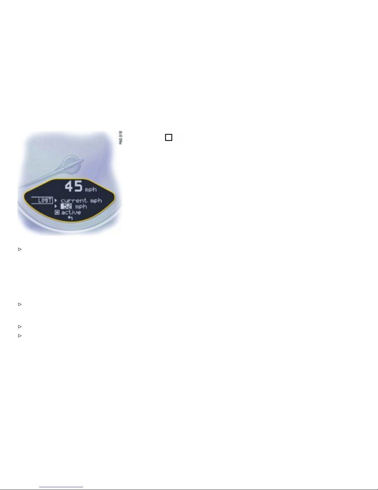
Push operating lever slightly up or down until
the desired s peed is reached.
upwards: speed is increased
downwards: speed is decreased
Note
Holding the lever up or down for a longer period will
adjust the speed in steps of 6 mph (10 km/h).
Push operating leve r forwa rd.
Switc hing the acoustic warni ng signa l off
Select “LIMIT active” with the operating lever.
Push operating leve r forwa rd.
Display:
110Controls, Instruments
Downloaded from www.ManualsFile.com manuals search engine
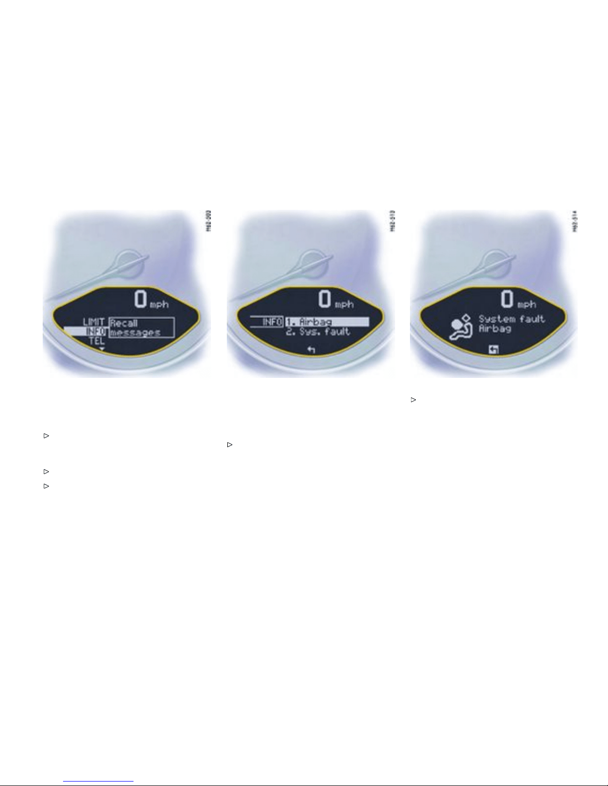
INFO W arning me ssages
Switching on selection eld “D”
Push operating lever forward.
Calling warning messages
Select INFO with the operating lever.
Push operating lever forward.
Any existing warnin g me ssages can be called
using the operating leve r. You a lso can call w arning
messages which were cancelled during the trip (but
only until the next time the ignition is switched on).
Push operating lever forward.
Push operating lever forwards or pull back-
wards. The display returns to the Info menu.
Controls, Instruments
111
Downloaded from www.ManualsFile.com manuals search engine

TEL Telephone information
Switching on selec tion eld “D”
Push operating leve r forwa rd.
Calling telephone information
Select TEL with the operating lever.
Push operating lever forward. Note
You can recall phone calls, e.g. calls that arrived
during your absenc e, via the menu item “Missed
calls”.
112Controls, Instruments
Downloaded from www.ManualsFile.com manuals search engine
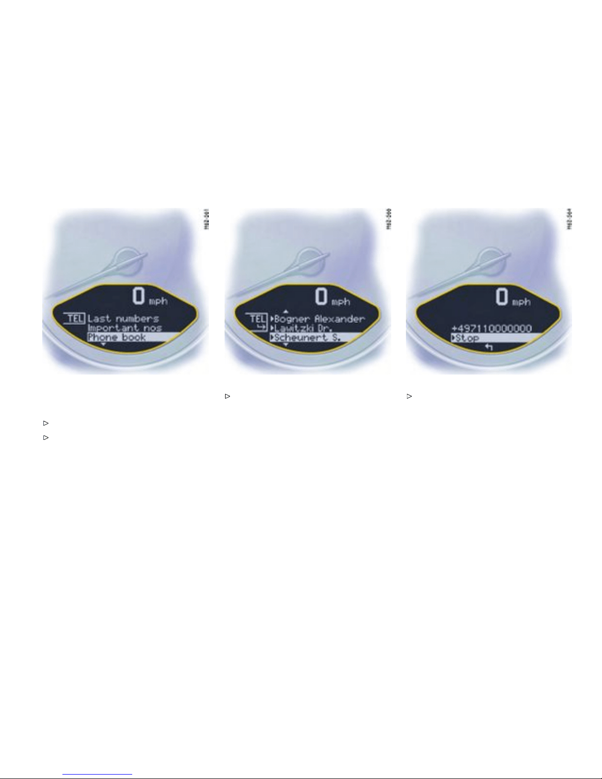
Examp le: Selecting from the telephone
book and calling
Select “Phone book” with the operating lever.
Push operating lever forward.
Select a person to call and push the opera ting
lever forward. The connection is established.
Push the operating lever forward to end the
call.
Controls, Instruments
113
Downloaded from www.ManualsFile.com manuals search engine

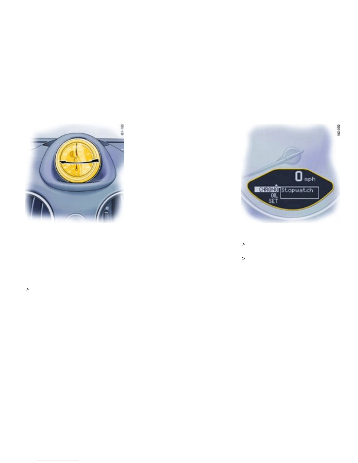
CHRONO Stopwatch
Function
You can use the stopwatch to measure time
intervals , e.g. on the race circuit o r on work-related
journeys. Meas u red lap times can be stored and
evaluat ed if the vehicle is equipped with Porsche
Communication Management (PCM).
Please observe the chapter “Sport display” in
the separate PCM operating instructions.
Stopwatch on the instrument p anel
The stopwatch has an analogue and a dig ital
display. The large poi nter of the analogue display
measures the seconds. The two small pointers
measure hours and minutes. Th e dis p lay re-starts
at zero after 12 hours. Seconds and increments
of 1/100th of a second can be read on the digital
display. The digital display and the d isplay in the
on-board compute r can indicate up to 99 hours and
59 minutes.
The stopwatch can be swivelled both to the left and
to the right.
Stopw atch displays:
– on the stopwatch on the instrument panel ,
– in the on-board computer menu CHRONO,
– on the perfor mance display in the PCM.
Starting/stopping stopwatc h
All stopwatch displays are start ed and stopped via
the on-board computer menu CHRONO.
Note on operati on
When you leave the CHRONO menu while the
stopwa tch is running, measurement will continue.
The stopwatch stops after the ig nition is switched
off. If the ignition is switched on again within
approx. 4 minutes, the stopwatch will continue
to run.
The only way to reset the stopwatch to zero is by
selecting “Reset” in the CHRONO menu.
Starting the timing
Push operating lever forward. The selection
field is switched on.
Select CHRONO with the operating lever.
Controls, Instruments
115
Downloaded from www.ManualsFile.com manuals search engine
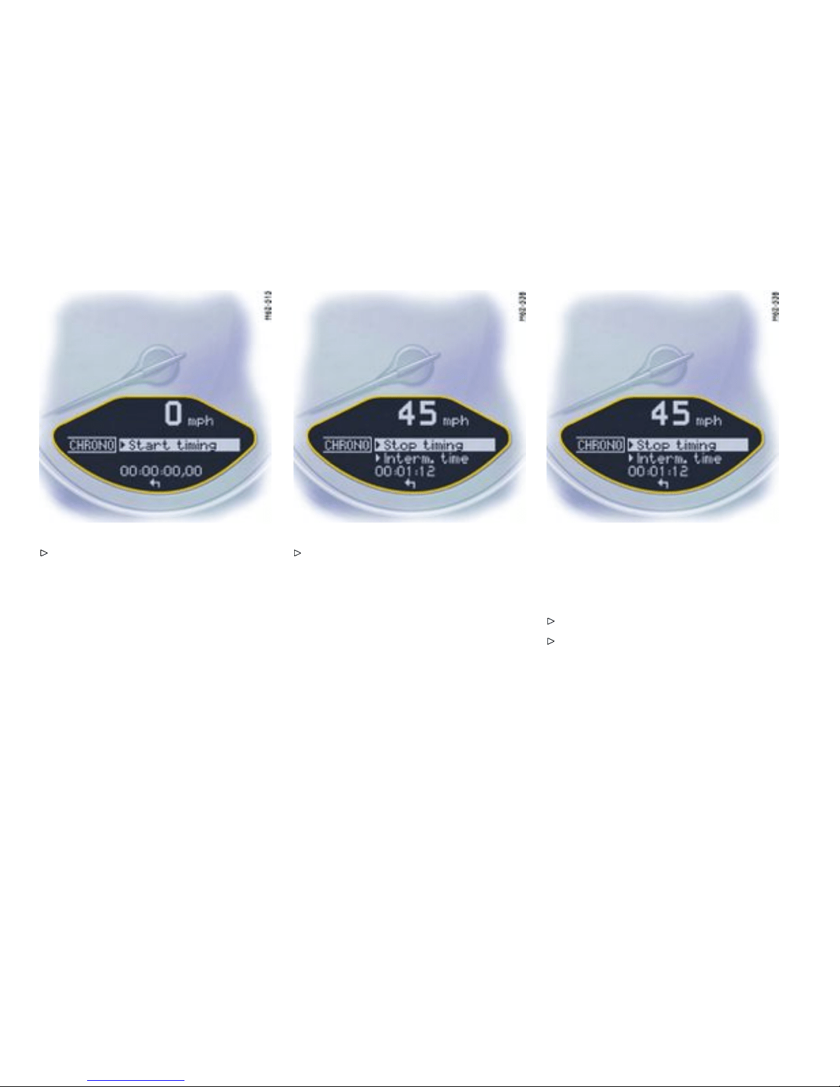
Push operating leve r forwa rd. Push operating lever forward. The time runs
on all stopwatch displays. The on-board
computer display changes to the “Stop
timing /Intermedi ate time” selection.
Note
PCM: The performance display in the “Trip/Sport
display/Begin trip” menu must be selected in order
to analyse the data in the PCM.
Stopping the timing
After time measurement is started, the on-board
computer display changes to the “Stop tim-
ing/In termediate time ”.
Select “Stop timin g” with th e operating lever.
Push lever forward. The time is stopped in all
stopwatch displays, and the on-board compu-
ter display changes to the “Continue/Reset”
selection.
116Controls, Instruments
Downloaded from www.ManualsFile.com manuals search engine
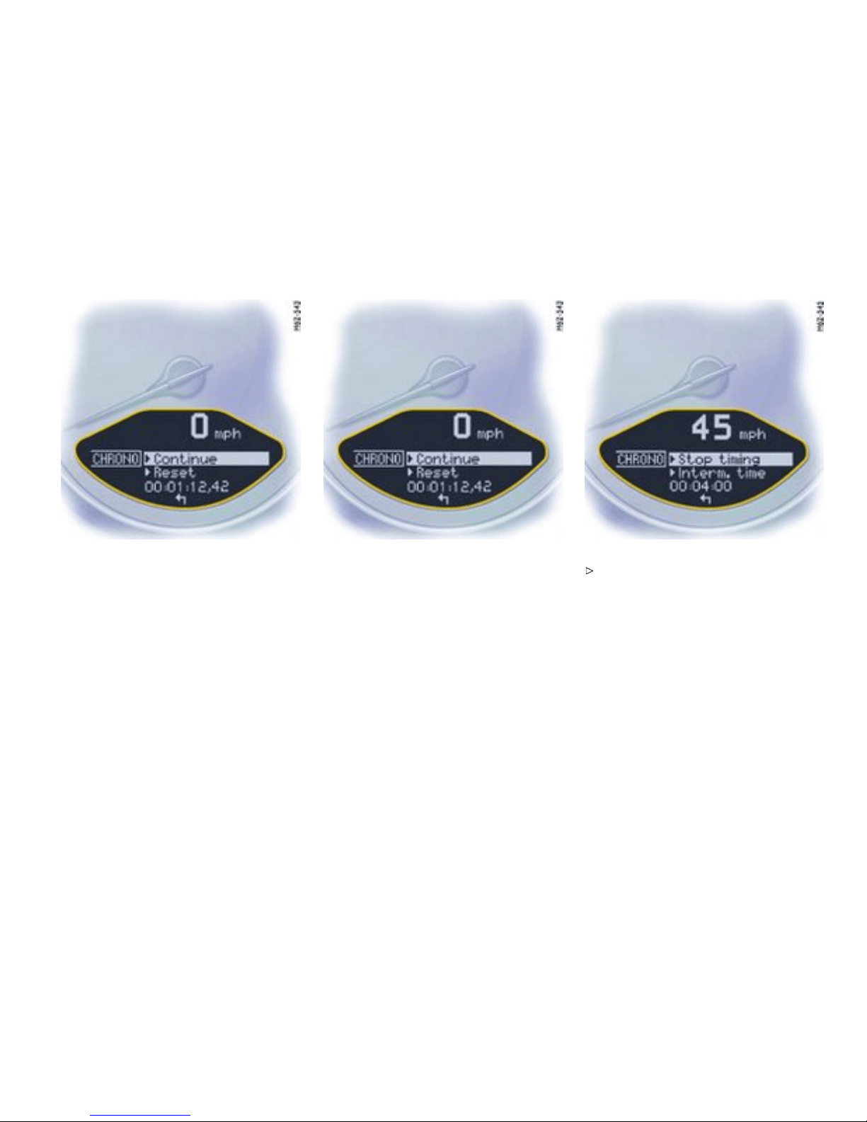
The timing can be continued or reset to zero.
Note
PCM: After timing has been stopped, a prompt
asking whether the time is to be stored appears on
the PCM.
Continue timin g
After timing has been stopped , the on-board
computer display changes to the “Continue/Reset”
selection.
Push operating lever forward. The stopwatch
displays continue the timing.
The on-board computer display returns to the “Stop
timing/ Intermediate time” selection. You can stop
the stopwatch or measure an intermediate time.
Controls, Instruments
117
Downloaded from www.ManualsFile.com manuals search engine

Resetting the time
After timing has been stopped, the on-board
computer display changes to the “Continue/Reset”
selection.
Select “Reset” with the operating l ever.
Push operati ng lever forward. The display
returns to the “Start timing ” selection. Th e
stopw atch displays in the instrument panel and
the on-board computer are reset to zero.
118Controls, Instruments
Downloaded from www.ManualsFile.com manuals search engine

A - Lap
B - Intermediate time
Displa ying intermediate times
Several intermediate times can be displayed for a
route or for a lap on the race circuit. The interme-
diate times B are for your information. Measured
lap times A can be stored and evaluated if the
vehicle is equipped with Porsche Communication
Manage ment (PCM).
To display an intermediate time:
After timing has been started, the on-board c o mpu-
ter display change s to the “Stop timing/In termedi-
ate time” selection .
Select “Inte rmediate time” with the operating
lever and push the operating lever forwards.
The intermed iate time will be displayed for approx.
5 seconds. The on-board computer display then
returns to the “Stop timing/Intermediate time”
selection.
Controls, Instruments
119
Downloaded from www.ManualsFile.com manuals search engine

You can stop the stopwatch or measure
another intermediate time.
In order to start timing a new lap:
The “New lap?” selection appears for 5 seconds
after selection of “Intermediate time”.
Select “New lap?” with the operating lever and
push the operating lever forwards.
The new lap i s displayed on the on-board computer
and the PCM. Timing on the on-board computer and
on the PCM begins from zero. The stopwatch in the
instrument panel continues to show the total time.
The on-board computer display returns to the
“Stop timing/Intermediate time” selection
after a short period.
120Controls, Instruments
Downloaded from www.ManualsFile.com manuals search engine

You can stop the stopwatch or measure
another intermediate time or a new lap.
Note
PCM: If you wish to store the lap time in the
PCM, the performance display in the “Trip/Sport
display/Begin trip” menu of the PCM must be
selected.
Controls, Instruments
121
Downloaded from www.ManualsFile.com manuals search engine

TPC Tire Pressur e Monitoring
Function
Please observe the chapter ”TIRE PRESSU RE
FOR COLD TIRES” on page 299.
The Tire Pressure Monitoring continuously moni-
tors tire pressure and ti re temperature on all four
wheels and warns the driver when the tire pressure
is too low.
The display as well as the settings for the Tire
Pressure Monitoring take place on the on-board
computer. However, you must still adjust the tire
pressure on the wheel.
The driver is responsi ble for fi lling the tires
correctly and making the correct settings on
the on-board computer.
The Tire Pressure Monitoring offers the following
functions:
– Display of the actual tire pressure while the
vehicle is in motion
– Display of the deviation from the required
pressure (refilling pressure)
– Displa y of currently set t ire size and type
– Tire pressure warnings in t wo stages
Caution!
Despit e the advantages offe red by the Tire
Pressure Monitoring, it is still the driver’s
responsibility to update the corresponding
settings in the on-boa rd computer and
maintain the pressure in the t i res. Low tire
pressure reduces the road safety of the
vehicle and destroys the tire and whe el.
When a flat tire has been displayed, immediate-
ly stop in a suitable place and check the tires
for damage. If necessary, remedy the damage
with a tire sealant.
Do not by any means continue to drive with
defective tires.
Sealing the tire with tire sealant is only an
emergency repair, so you can drive to the next
authorized Porsche dealer. T he maximum
permit ted speed is 50 mph ( 80 km/h).
Do not drive with tires wh ose tire pressure
drops again in a short period of time. In cases
of doubt, have tires checked by an authorized
Porsche dealer.
Damaged tires must be immediately replaced
by an authorized Porsche dealer. Tire
repairs are not permissible under any
circumstances.
If the Tire Pressure Monitoring is defective
(e.g. defective wheel transmitter), contact
an authorized Porsche dealer immediat ely
and have the damage repaired. The tire
pressure will not be monitored by a defe ctive
Tire Pressure Moni toring.
Tires l ose air o ver time without a tire defect
being present. A tire pressure warning
will then appear in the on-board computer
display. C orrect the tire pressure at the next
opportunity.
The Tire Pressure Monitoring gives a warning
about tire damage due to natural pressure loss
as well as about a gradual loss of pressu re
due to foreign objects. The Tire Pressure
Monitori ng cannot warn you about tire damage
that occurs suddenly (e.g. flat tire due to
abrupt external effects).
122Controls, Instruments
Downloaded from www.ManualsFile.com manuals search engine
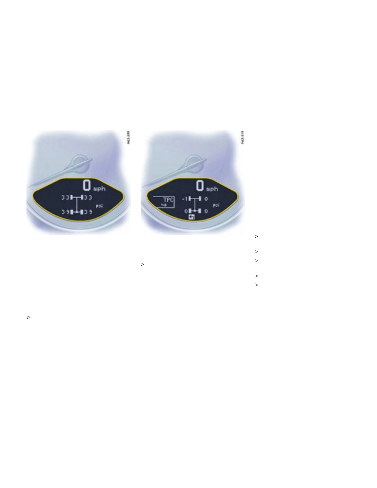
Setting s in t he on-board computer
Tire pressure function o f the on-board
computer
The tire pressure function of the on-board compu-
ter displays the tire pressures (actual pressure)
dependent on te mperature in the four wheels. You
can watch the tire pressure rise as the temperature
increases while driving. This display is only for
information.
Under no circumstances should the tire
pressures be changed based on this display.
Calling th e tire pressure function of the
on-board computer
Push operating lever up or down until the
tire pressure function of the on-board com-
puter appear s. (The selection field must be
switched off.)
Pressure info in Tire pressure menu
In accordance with physical principle s, the air
pressure changes as the temperature changes.
The tire pressure increases or decreases by
around 1.5 psi (0.1 bar) for every 18°F (10°C )
change in temperature.
The Tire Pressure Monitoring takes this relationship
between tire pressure and temperature into
account.
You can read the tire p ressures to be correct-
ed in this display.
The tire pressure to be corrected (refill pressu re)
is indicated on the displayed wheel. Example: If “
-1.5 psi (-0.1 bar)” is displayed, 1.5 psi (0.1 bar)
must be added to this tire.
Note
The Tire pressure menu can only be called up when
the vehicle is stationary.
Calling u p the “Info pressure” display
Push operating lever forward in order to switch
on the selection field.
Select “TPC” with the operating lever.
Push operati ng lever forward. The display
change s to the Tire pressure menu.
Select “Info pressure” with the operating lever.
Push operating lever forward.
Note
After the ignition is switched on, it can take up
to approx. 1 minute before all tire pressures are
displayed. Dashe s (“-.-”) appear instead of the tire
pressures.
Controls, Instruments
123
Downloaded from www.ManualsFile.com manuals search engine

Tire type info in Tire pressure m enu
Information about the currently set tires:
– Tire type: Summer tires, winter tires
– Tire size: 17, 18, 19 inch
“Info tires” shows the current tire settings.
Calling up the “Info tires” display
Push operating leve r forwa rd in order to switch
on the selection field.
Select “TPC” with the operating lever.
Push operating lever forward. The display
changes to the Tire pressure menu.
Select “Info tires” with the operating lever.
Push operating lever forward.
Tire selection in th e “Set” menu
Push operating lever forward in order to switch
on the selection field.
Select “TPC” with the operating lever.
Push operating lever forward. The display
changes to the Tire pressure menu.
124Controls, Instruments
Downloaded from www.ManualsFile.com manuals search engine

Select “Set” with the operating lever. Push the operating lever forward.
Select desired tire type: summer or winter.
Push operating lever forward. A display for
confirming the s elected type of tire appears.
Select “Continue” and push the operating lever
forwa rd.
Controls, Instruments
125
Downloaded from www.ManualsFile.com manuals search engine
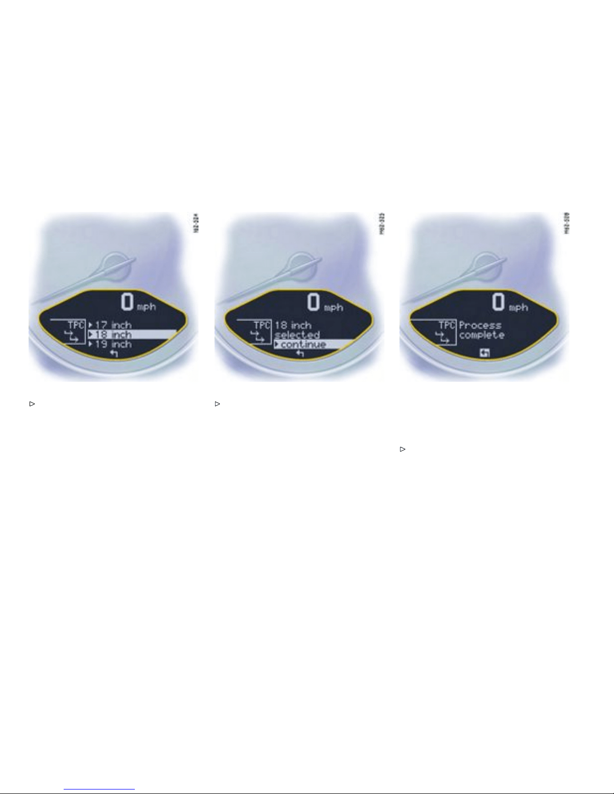
Select the appropriate tire siz e
(17, 18 or 19 inch) and push operating
lever forwards. A display for confirming the
selected tire size appears.
Note
This menu is only displayed when different tire
sizes are approve d .
Select “Continue” and push the operating lever
forwa rd.
Setting of the tire characteristics has only been
succes sfully completed when the message
“Process complete” is displayed by the on-board
computer.
Select arrow (Back) and push the operating
lever forward. Th e display returns to the
Tire pressure menu. The on-board computer
additionally displays the message “Syst em
learning”.
Note
The messag e “Process aborted” appea rs if the
setting process is interrupted. All entries made
up to this point are lost, and the original settings
remain in e ffect. Only if t he message “Process
126Controls, Instruments
Downloaded from www.ManualsFile.com manuals search engine
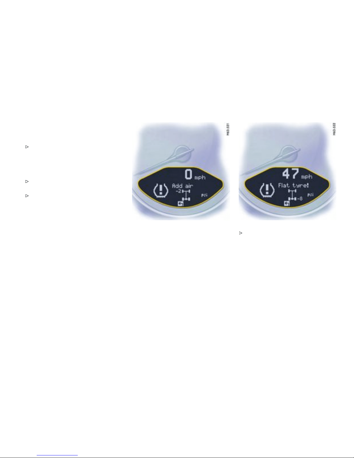
complete” appears after the settings have been
made will the Tire Pressure Monitoring re-learn the
wheels.
Please observe the chapter ”SYSTEM LEARN-
ING” on page 128.
Before fitting tires with sizes which are not stored
in the on-board computer, the missing information
should be supplemented in the on-board computer.
Please consult your authorized Porsche
dealer.
Use only tires approved by Porsche.
The available items in the Tire pressure menu
depend on the equipment of your vehicle. For this
reason it is possibl e that some of the items shown
here are not availabl e on your on-board computer’s
display.
Tire pre ssure warnings
The Tire Pressure Monitoring warns about loss in
pressure in two stages, depending on the amount
of pressure loss:
Stage 1 - Add air
(3 to 6 psi (0.2 to 0.4 bar) loss in pressure)
Stage 2 - Flat tire
(from 6 psi (0.4 bar) loss in pressure)
Stage 1 - Add air
The pressure in the tire is too low by 3 to 6 psi (0.2
to 0.4 bar). Drivin g with insufficient tire pressure
reduces the road safety of the vehicle and destroys
the tire and wheel.
The tire pressure warning contains the
affected tire with the tire pressure to be
added. Correct the tire pressure at the next
opportunity.
This tire pressure warning appears with vehicle
stopped and can be acknowledged. The tire
pressure warning light in the instrument panel goes
out when the tire pressure has been corrected.
Stage 2 - Flat tire
The pressure in the tire has dropped by more than
6 psi (0.4 bar). This significant pressure loss is a
danger to road safety.
Controls, Instruments
127
Downloaded from www.ManualsFile.com manuals search engine

When the tire pressure warning has appeared
on the on-board computer, stop immediately at
a suitable location. Check the tire for signs of
damage. If necessary, fill in tire seal ant and set
the correct tire pressure.
This tire pressure warning appears when driving
and can be acknowledged. The tire pressure
warning light in the instrument panel goes out when
the tire pressure has been corrected.
System learning
The Tire Pressure Monitoring begins to “learn” the
wheels after a wheel change, wheel transmit t er
replacement or update of the tire settings. During
this process, the Tire Pressure Monitoring recog-
nizes the tires an d their locations. T h e on-board
compute r displayes the message “TPC inacti ve -
system learni ng”.
The Tire Pressure Monitoring requires a certain
amount of time to learn the wheels. During this
time, the current tire pressures are not available on
the on-board-computer:
– The display of the Tire pressure function of the
on-boa rd computer shows lines.
– The required pressures for cold tires at
68°F (20°C ) are indicated in the Info pressure
display in the Tire pressure menu.
– Tire p ressure warnings are iss ued without tire
pressure and position information (gure) as
soon as the vehicle’s own wheels have been
detected and the tire pressure warning light
has gone out.
Position and pressure information is displayed as
soon as the Tire Pressure Monitoring has assigned
the wheels identified as belonging to the vehicle to
the correct wheel positions.
The wheel learning process takes place exclusively
when the vehicle is being driven.
Manua lly check the tire pressure at all wheels
and correct the tire pressure to the required
value.
Changing a wheel and replacing tires
New wheels must be fitted with radio transmit-
ters for the Tire P ressure Monitoring. Before
tires are changed, the battery charge state of
the wheel transmitters should be checked at
an authorized Pors che dealer.
Switch the ignition off when changing a wheel.
The tire settings on the on-board computer must be
updated after changing a wheel.
A message appears if the characteristic s of the
new tires do not agree with the on-board computer
settings.
Update the on-board computer settin gs when
the vehicle is stationary the next time.
Warning light
The warning light in the speedometer lights up:
– When a loss in pressure has been detected
– If the T ire Pressure Monitoring is faulty
– When learning newly mounted wheels/wheel
sensors, as long as the vehicle’s own wheels
have not yet been recognized.
The tire pressure warning light in the instrument
panel goes out only when the cause o f the fault has
been rectified.
128Controls, Instruments
Downloaded from www.ManualsFile.com manuals search engine

No monitoring
In the event of faults the Tire Pressure Monitoring
cannot monito r the tire pressure. The warning
light on the in strument panel lights up and a
correspondin g message appears on the on-board
computer.
Monitoring is not active when:
– the Tire Pressure Monitoring is faulty,
– wheel transmitters for the Tire Pressure
Monito ring are missing,
– temporarily after changing a wheel (learning
phase),
– more than four wheel transmitters are detect-
ed,
– there is exter nal interference by other radio
sources, e.g. wireless headphones,
– tire temperatures are too high .
Please observe the chapter ”WARNINGS
ON THE INSTRUMENT PANEL AND THE
ON-BOARD COMPUTER” on p age 138.
Controls, Instruments
129
Downloaded from www.ManualsFile.com manuals search engine
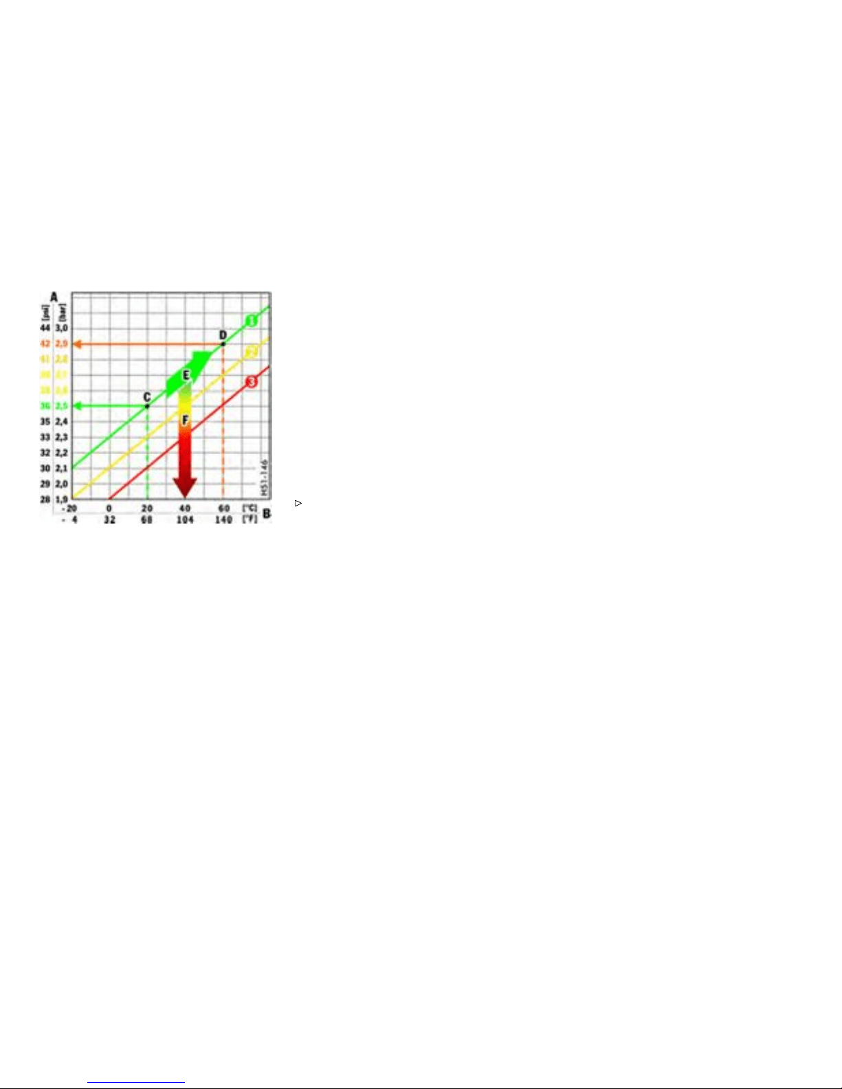
A Tire pressure
B Tire temperature
C Tire pressures for cold tires
D Tire pressure for hot tires
E Pressure increase as the result of tempera-
ture increase
F Pressure drop in faulty/leaking tires
1. Required-pressure line
2. Warning stage 1 (from - 3 to -6 psi (-0.2 bar
to -0.4 bar))
3. Warning stage 2 (from - 6 psi (-0.4 bar))
Pressu re increase as the resul t of
tempe rature increase
In accordance with physical principle s, the a ir
pr
essure changes as the temperatu re changes.
The tire pressure increases or decreases by
around 1.5 psi (0.1 bar) for every 18°F (10°C )
change in temperature.
The Tire Press u re Monitoring takes this relationship
between tire pressure and temperature into
account.
Tire pressure specications
Information on tire pressure for public roads can
be found in this Owner’s Manual in the Technical
Data chapter or on the tire-pressure plate in the left
door aperture. These value s apply to cold tires at
68°F (20°C ).
Please obser ve the chapter ”TIRE PRESSURE
FOR COLD TIRES ” on page 299.
130Controls, Instruments
Downloaded from www.ManualsFile.com manuals search engine
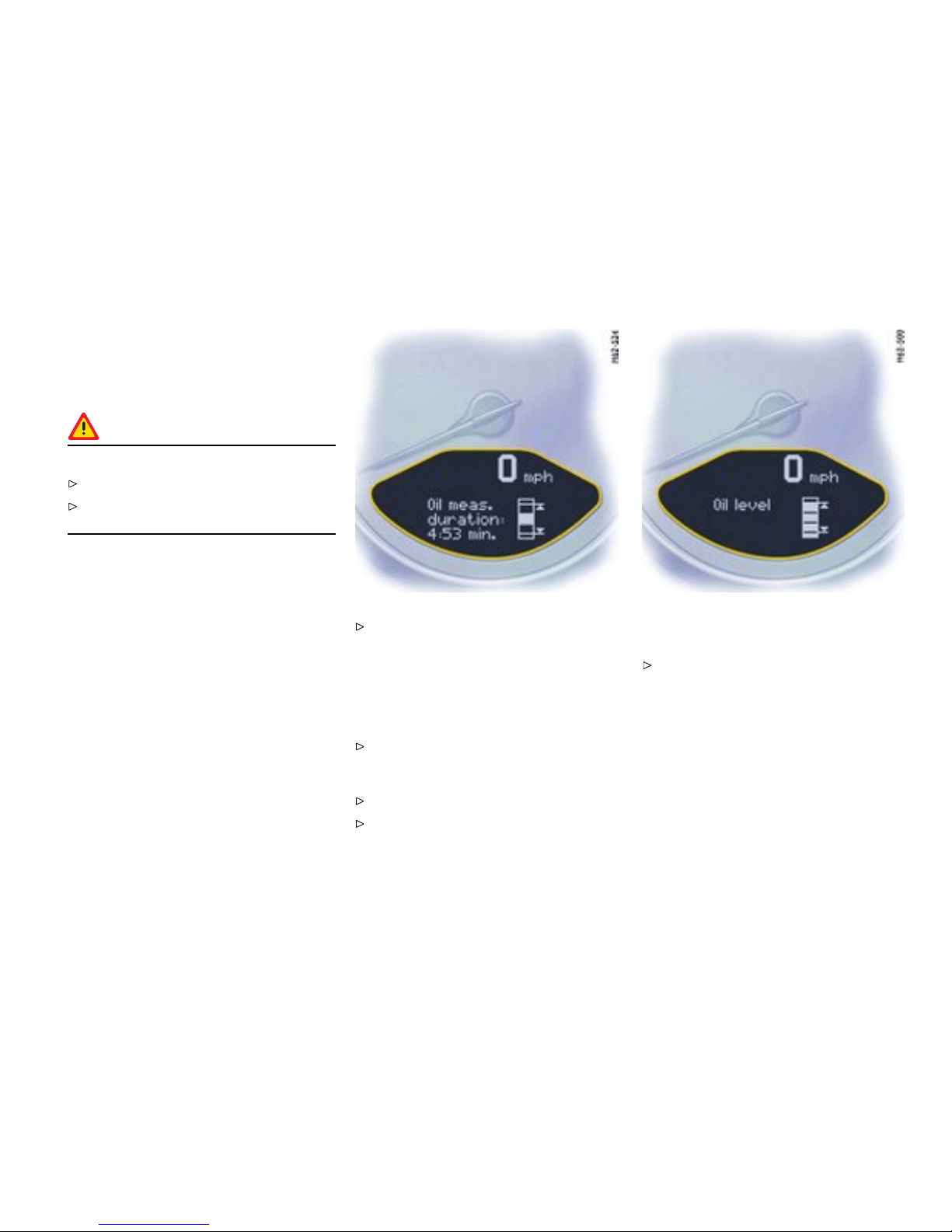
OIL Di splay and measurem ent of
the engi ne oil level
Conditions for measuring the oil level
Caution!
Risk of engine damage.
Regularly check the oil level after refueli ng.
Do not allow the oil level to fall below the
minimum mark.
1. It is imp ortant to ensure that the vehicle is
horizontal for correct oil level measurement
to occur.
2. Engine is off.
3. Ignition on.
Oil return ti me
Before the o il level is measured, the engine oil
has to have flowed back into the oil pan. The time
taken for the engine oil to flow back depends on the
engine temperature and how long the engine has
been stopped.
This waiting time is counted down in the on-board
computer display when the ignition is switched on.
The oil level display segments start to “cycle”.
It is best to measure the engine oil level before
embarking on a journey (if the vehicle has not
been driven for an extended period) or with
the engine at operating tempe rature. Shorter
waiting times are achieved in this way.
Initiating oil level measurement
Switch ignition on (do not start the engine).
The engine-oil level measurement display
appears in the on-board computer.
Allow waiting time to elapse.
Once the measurement has been complete d,
you can read off the engine oil level on the
segment display.
– If the segments are filled in up to the top line,
the oil level has reached the maximum mark.
Under no circumstances add engine oil.
Controls, Instruments
131
Downloaded from www.ManualsFile.com manuals search engine
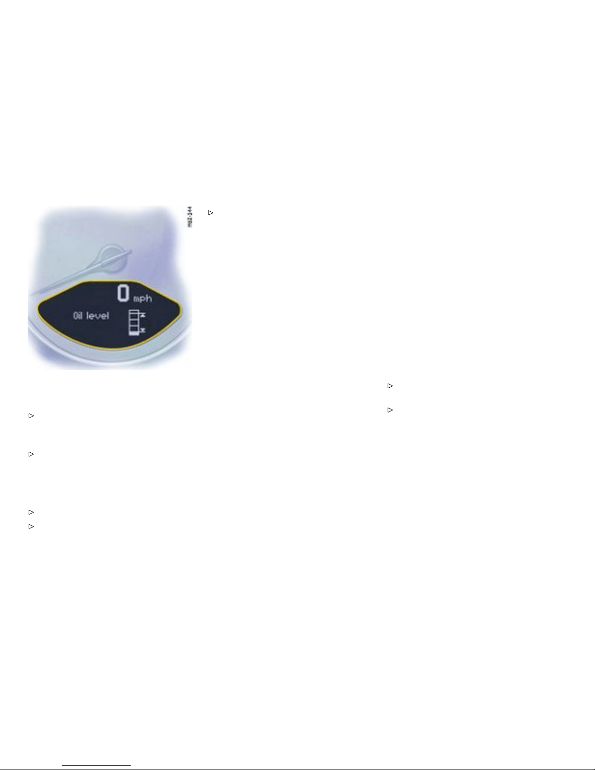
– If only the bottom segment is filled in, the oil
level has reached the minimum mark.
Add engine oil immediately.
– If the bottom segment flashes, the oil level has
dropped to below the minimum mark.
Add engine oil immediately.
The difference between the minimum and max-
imum marks on the segment display is approx.
1.2 liters. Each segment of the display corre-
sponds to approx. 0.4 liter.
Add engine oil if necessary.
Please observe the chapter ”ENGINE OIL
LEVEL” on page 208.
Never add more engine oil than required
to reach the maximum mark.
Oil level measurement during refueling
The oil level is automatically measured du ring
refueling.
Preconditions
1. Ignition is switched off.
2. If the engine is at operating tempera ture, at
least 5 minutes must elapse between parking
the vehicle and starti ng the e ngine.
3. Refueling completed within 15 minutes.
When the ignition is switched on, the engine oil level
is shown on the segment display.
Measurement will be stopped if the above require-
ments are n ot met.
Start oil level measurement in the “OIL“ menu
or
Start oil level measurement by switching on
the ignition.
Failure
A failure of the oil level display is indicated by a
warning message in the o n-board computer.
132Controls, Instruments
Downloaded from www.ManualsFile.com manuals search engine
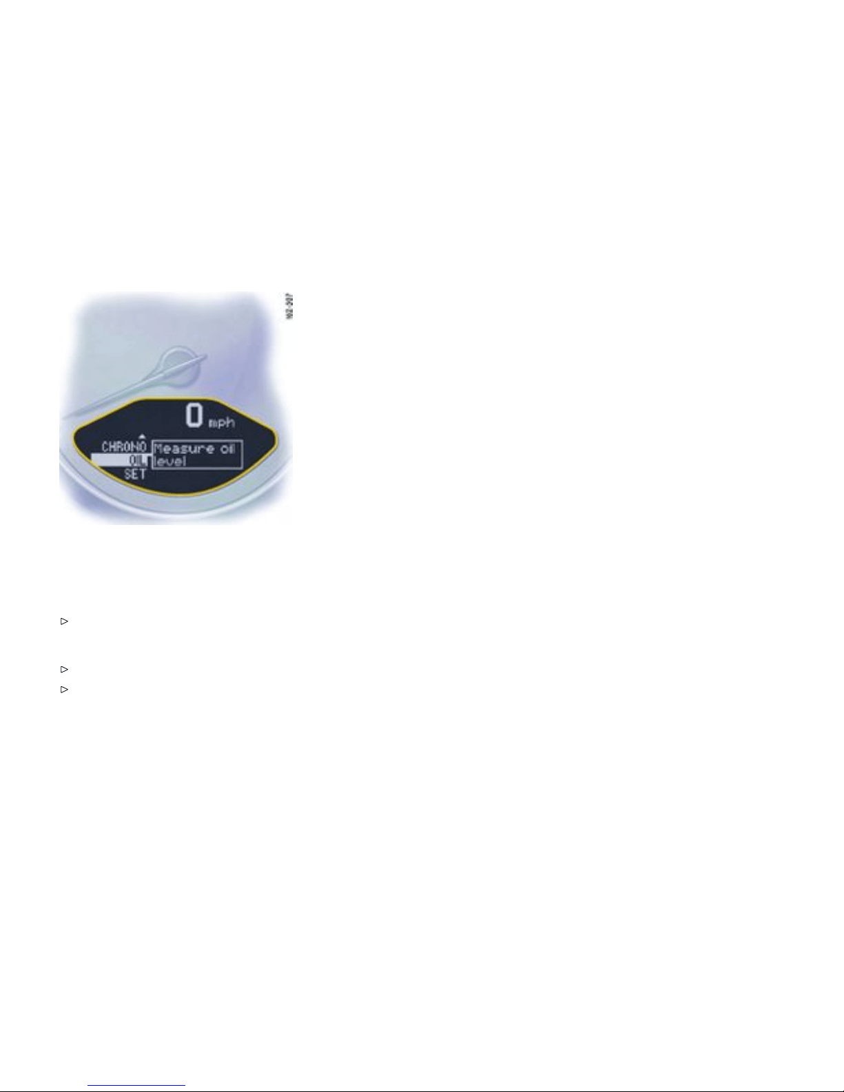
The oil level measurement can al so be
initiat ed in the “OIL” menu:
Switching on selection eld “D”
Push operating lever forward.
Initiating measurement
Select “OIL” with the operating lever.
Push operating lever forw ard. Measurement is
started.
Controls, Instruments
133
Downloaded from www.ManualsFile.com manuals search engine
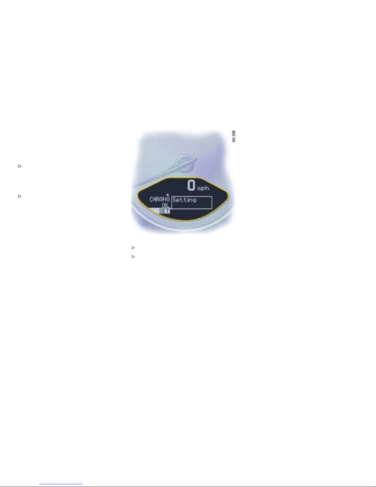
SET Basic settin g on o n -board
computer
Switching on selec tion eld “D”
Push operating leve r forwa rd.
Changi ng the basic setting of the on- board
computer
Select “SET” with the operating lever.
Push operating lever forward.
Select the desired function with the operating
lever:
134Controls, Instruments
Downloaded from www.ManualsFile.com manuals search engine

Reset
– Reset all,
– Reset average consumption,
– Reset average speed,
– Reset trip counter
Units
– Speedometer: km - km/h, miles - mph
– Consumption: l/100 km, mls/gal (USA),
mpg (UK), km/l
– Temperature: Celsius, Fahrenheit
– Tire pressure: bar, psi
Display ( Select ce ntral line of the
on-b oard computer)
Change display
– Audio information (set radio station)
– Rang e on remaining fuel
– Empty
Telepho ne Info
– When Telephone information is active, incom-
ing telephone calls are d isplayed on the
on-board computer.
Controls, Instruments
135
Downloaded from www.ManualsFile.com manuals search engine

Navigat ion
– Integrated in the BC (Navigation instructions
can be recalled on the on-board computer
display)
– When turning off (Navigation instructions are
only shown before changing direction)
Basic setting
– Restore the basic s etting of the on-board
computer
Language
– Select langua ge version
12/24h mode
Select time mode:
– 12h (small squares on the right side of the time
display for AM/PM),
– 24h
136Controls, Instruments
Downloaded from www.ManualsFile.com manuals search engine

General information regarding the
on-board computer functions
Range on remaining fuel
The range on remaining fuel i s continuously
recalculated during the journey base d on the
fuel level, current consumption and average
consumption. The more the fuel level falls, the
more spontaneously the display reacts. For
this reason, the range on remainin g fuel is not
displaye d if less than 9 miles (15 kilometers).
If the v ehicle’s inclination changes while driving
or refueling, incorrect range informatio n may
tempor a rily be given.
Note
If the tank is nearly empty and you top up with
only a small quantity of fuel, an accurate range on
remaining fuel is impossibl e.
Average c onsumption and average speed
The values displayed are based on the distance
travelled since the last reset to “zero”.
You can set the starting time for a measurement
before or during the trip. Switch ing the ignition off
does not reset the measurements. It is therefore
possible to collect values over long periods .
Disconnecting the car battery will cause these
memories to be erased.
Tire pressure
The Tire pressure function of the on-board
computer displays the tire pressures dependent
on temperature in the four wheels. You can watch
the tire pressure rise and fall while driving. The
display is only for information . To correct the tire
pressures, always use the displayed values from
the “Info pressure” disp lay in the Tire pressure
menu.
Controls, Instruments
137
Downloaded from www.ManualsFile.com manuals search engine

Warnings on the instrument panel and the on-board computer
Overview of the warnings
If a warning message appears, always refer to the corresponding chapters in the Owner’s Manu al. Warning messages are issued only if all measurement precon-
ditions are met. Therefore, check all fluid levels regularly - in particular, always check the engine oil level after refueling.
Instru ment panel
On-board computer
Text display on on-board
computer
Meaning/me asure
Seat belt Driver and passengers must fasten
their seat belts.
Handb rake Handbrake is still on.
Ignition key not removed
Replace battery in ignition key Replace the remote-control battery.
Ignition lock faulty, please go to
workshop
Have the fault remedied at an
autho rized Porsche dealer.
Ignition lock fault y, visit workshop
now
Have the fault remedied at an
autho rized Porsche dealer.
Relieve steeri ng Relieve the steering lock by moving
the steering wheel to the left or right.
Steering locke d
The steering wheel lock remains
engaged. Have the fault remedied at
an authorized Porsche dealer.
Lights on Low beam/side light on.
138Controls, Instruments
Downloaded from www.ManualsFile.com manuals search engine
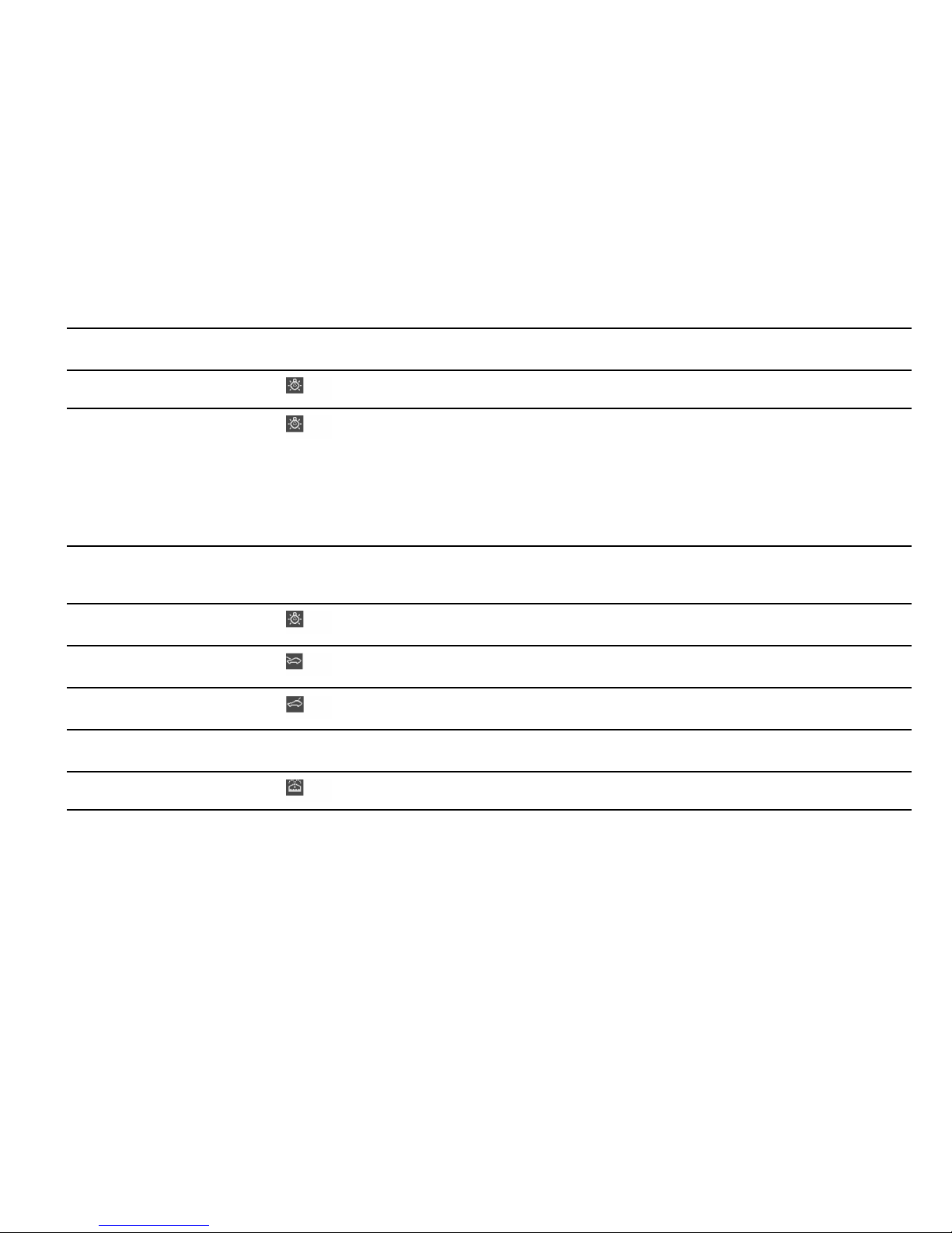
Instrument panel
On-board computer
Text display on on-board
comp uter
Meaning/measure
Parking light on
Left/rig h t parking light on.
Check left/right dipped beam (low
beam)
also applies to:
front side lights, direction indicator,
high beam, fog lights, side indicator
light, brake light, tail light, rear fog
light, reversing light, raised brake
light, side marker
The reported light is faulty. Check
bulb. Have the fault remedied at an
authorized Pors che dealer.
Daytim e driving l ights off Daytime driving lights switch off
when the engine is shut off. Switch
on lights if necessary.
Headlight beam adjustment faulty Have the fault remed ied at an
authorized Pors che dealer.
Front lid not closed
Close luggage com partment lid
properly.
Rear lid not closed
Close engine compartme nt lid
properly.
Rain sensor faulty Have the fault remedied at an
authorized Pors che dealer.
Refill washer fluid
Controls, Instruments 139
Downloaded from www.ManualsFile.com manuals search engine
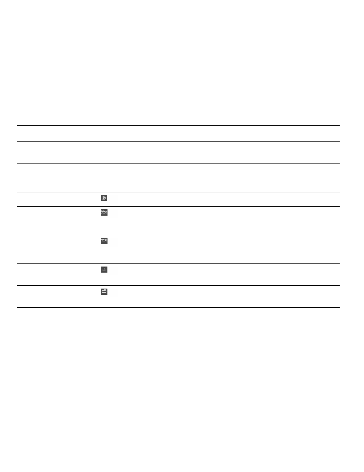
Instru ment panel
On-board computer
Text display on on-board
computer
Meaning/me asure
LIMIT
Cannot be accepted with vehicle
stopped
The current speed can only be
accep ted for the acoustic warning
signal when the vehicle is in motion.
LIMIT 30 Selected speed limit (e.g. 30 mph)
for the acoustic warning signal has
been exceeded. Adjust your s peed if
necessary.
Fuel gauge warning light
Consider remain ing range Refuel at next opportunity.
Check engine oil level Start engine oil l evel measurement in
the on-board computer.
The vehicle must be horizonta l and
the ignition must be switched on.
Engine oil pressure too low
Stop immediately at a suitable place,
measure oil level with the on-board
compu ter and, if necessary, add
engine oil.
Warning light
Temperature gauge
Engine temperature too high
Switch engine off and let it cool.
Check coolant level and, if neces-
sary, add coolant.
Temperat u re gauge warning light
flashes
Check coolant level Switc h engine off and let it cool.
Check coolant level and, if neces-
sary, add coolant.
140Controls, Instruments
Downloaded from www.ManualsFile.com manuals search engine
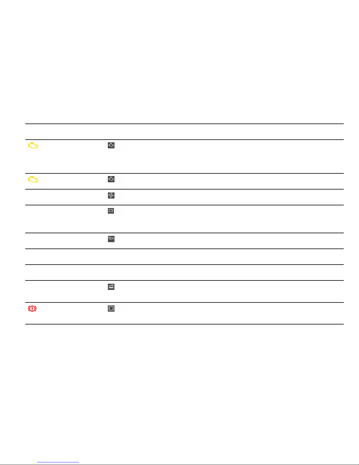
Instrument panel
On-board computer
Text display on on-board
comp uter
Meaning/measure
Engine diagnostics - workshop
Stop immediately at a suitable
place and check tank cap for
proper fastening. If the tank cap
was fastened correctly, consult an
authorized Pors che dealer.
Reduced engine power
Consult your authorized Porsche
dealer.
Temperature gauge warning light
flashes
Failure of engine compartment
blower
Consult your authorized Porsche
dealer.
Warning Battery/generato r
Stop at a safe place and switch
the engine off. Do not co ntinue
driving. Have the fault remedied at
an authorized Porsche dealer.
Oil pressure gau ge faulty Have the fault remedied at an
authorized Pors che dealer.
Oil level display faulty Have the fault remedied at an
authorized Pors che dealer.
Oil temperat ure gauge faulty Have the fault remedied at an
authorized Pors che dealer.
Indicator faulty Coolant indicator failed. Have the
fault remedied at an authorized
Porsche dealer.
Brake pad wear Have the brake pads changed
immediately at an authorized
Porsche dealer.
Controls, Instruments 141
Downloaded from www.ManualsFile.com manuals search engine
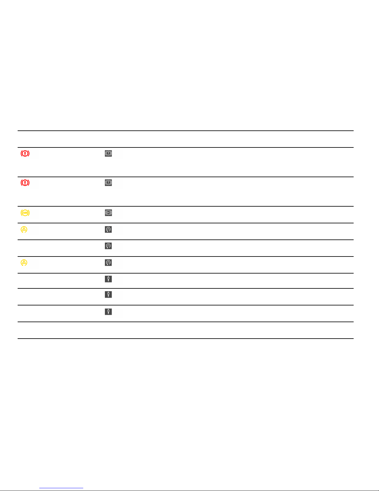
Instru ment panel
On-board computer
Text display on on-board
computer
Meaning/me asure
Warning - Brake fluid level Stop immediately in a suitable place.
Do not continue driving. Have the
fault remedied at an authorized
Porsche dealer.
Warning - Brake circuit division
Stop immedia tely in a suitable place.
Do not continue driving. Have the
fault remedied at an authorized
Porsche dealer.
ABS failure Have the fault remedied at an
autho rized Porsche dealer.
PSM off Porsche Stability Managem ent has
been switched off.
PSM on Porsch e Stabil ity Management has
been switched on.
PSM failure Have the fault remedied at an
autho rized Porsche dealer.
PASM Normal/Sport Indicato r for selecte d PASM mode
PASM failure Have the fault remedied at an
autho rized Porsche dealer.
PASM indicator faulty H ave the fault remedied at an
autho rized Porsche dealer.
Sport mode failure Have the fault remed ied at a n
autho rized Porsche dealer.
142Controls, Instruments
Downloaded from www.ManualsFile.com manuals search engine

Instrument panel
On-board computer
Text display on on-board
comp uter
Meaning/measure
Airbag system fault Airbag is faulty. Have the fault
remedied at an authorized Porsche
dealer.
Check passenger’s seat setting
Weight sensing is impaired o n the
passenger’s seat (Advanced Airbag).
When the backrest i s in contact with
the engine compartment wall, the
backrest can warp. Cor rect the
seating position, set the backrest
upright , do not support weight on the
armrests, or lift on the handles.
Failure spoiler control Driving stability is impaired. Adjust
your driving style. Reduce speed.
Have the fault remedied at an
authorized Pors che dealer.
Display of selector lever position
flashes
Selector lever i s not engaged Tiptronic S:
Selector lever can be between two
position s. Engage the selector lever
correctly.
Move selector lever to P
Tiptronic S:
Move selector lever to position P
before withdrawing key from ignition
lock.
Apply brake
Tiptronic S:
Apply the brake when start ing.
Controls, Instruments 143
Downloaded from www.ManualsFile.com manuals search engine

Instru ment panel
On-board computer
Text display on on-board
computer
Meaning/me asure
Depress clutch pedal Manual transmission:
Depress clutch pedal when starting.
Move select or lever to position
P or N
Tiptronic S:
The vehicle can be started only in the
select or lever position P or N.
Display of selector lever position
flashes
Tiptronic emergency run
Have the fault remedied at an
autho rized Porsche dealer.
Syste m fault
Go to workshop
Several systems may have failed.
Adjust your driving style. Reduce
speed. Have the fault remedie d at an
autho rized Porsche dealer.
Failure of fuel level indicator
Workshop
Have the fault remedied at an
autho rized Porsche dealer.
Service in mls/days (km/days) Service indicator
Bring the vehicle in for service no
later than after the distance/time
shown has elapsed. Please observe
the additional i nformation in the
“Maintenance” bookle t.
Service now Service indicator
Have your vehicle servic ed at an
autho rized Porsche dealer.
144Controls, Instruments
Downloaded from www.ManualsFile.com manuals search engine

Instrument panel
On-board computer
Text display on on-board
comp uter
Meaning/measure
Flat Tire Tire Pressure Monitoring has
detected a serious pressure loss.
Stop in a suitable place and check
tires for damage. Fill in tire sealant if
necessary.
Add air The Tire Pressure Monitoring has
detected a gradual pressure loss.
Correct tire pressure at the next
opportunity.
TPC inactive
System learning
The Tire Pressure Monitoring is
learning the wheels on the vehicle.
The Tire Pressure Monitoring is
searching for the tires and their
position . During this period the
current pressure specification s
are not available on the on-board
computer.
TPC inactive
The Tire Pressure Monitoring is
faulty. Consult your authorized
Porsche dealer.
Controls, Instruments 145
Downloaded from www.ManualsFile.com manuals search engine

Instru ment panel
On-board computer
Text display on on-board
computer
Meaning/me asure
TPC inactive
Brief disturbance
TPC inactive
Too many wheel transmitters
The Tire Pressure Monitoring
is temporaril y deactivated by
excessive tire temperatures
(approx. 120 C (248F)) or
external interference (e.g. from
other wheel transmitters inside
the car). On ce the source of the
interference is removed, the system
is automatically reactivated.
Wheel chang e?
Input new TPC settings
Update the settings in the TPC menu
of the on-board computer at the next
opportunity. Wrong entries will affect
the correct pressure informatio n in
the menu. T he safety of your vehicle
is at risk.
TPC
Indicato r fault y
The display of the Tire Pressure
Monitoring system is faulty. Consult
your authorized Porsche dealer.
Acknowledging warning messages
Warning messages can be deleted from the on-board c omputer display.
Push the on-board computer ope rating lever forward.
You can recall erased warning mess ages in the “INFO” menu.
146Controls, Instruments
Downloaded from www.ManualsFile.com manuals search engine
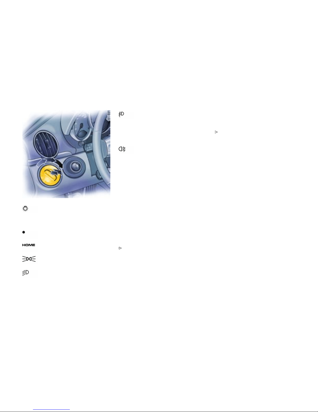
Light S witch
Switch settings
Lights switched off
Welcome Home Function
Parkin g lights, side marker lights,
license plate light, instrument illumination
Low beam, high beam
Only with ignition on
Fog lights in addition to parking lights or
low beam:
Pull switch to first click.
Indicato r light on.
The fog lights will go out automatically
when the high beams are switched on.
Rear fog light in addition to the fog
lights:
Pull switch to second click.
Indicato r light on.
Warning chime
If the ignition key is withdrawn and the door is
opened while the lights (not the parking light or
Welcome Home lighting) are on, a chime warns of
possible battery discharge.
In some countries, differences are possible
due to provisions of law.
Vehicles with Sport Chrono Plu s Package
Further individual light functi ons (e.g. daytime
driving lights) are available in vehicles with the
Sport Chrono P lus Package.
Please observe the chapter “Individu al
Memory” in the separate PCM operating
instructi ons.
Welcome Home Lighting
Switching on
Move light switch to the HOME position.
For improved visibility and security when you get in
and out of the car, the fog lights and the tail lights
remain on f or a certain period of time:
– When you get out of the car, the lights are
turned on for approx. 30 seconds after the
door is opened. The off-delay time resumes
when the vehicle is locked. On vehicles with
the Sport Chrono Pl us Package, the PCM
can be used to se t the off-delay time. This
setting also changes the lighting period for
unlocking the vehicle . Please observe the
chapte r “Individual Memory” in the separate
PCM operating instructions.
– The lights are turned on for approx. 30 sec-
onds when the vehicle is unlocked. The
lights go out if the ignition is switched on or
when leaving the Welcome Home lighting.
If the ignition key is withdraw n and the door is
opened while the lights (not the parking light
left/right) are on, a gong warns of po ssible battery
discharge.
In some countries, differences are possible
due to provisions of law.
Controls, Instruments
147
Downloaded from www.ManualsFile.com manuals search engine

Automatic Head light Beam Adjustme nt
Function
Vehicles with Bi-Xenon head lights feature
automa tic headlight beam adjustment.
When the ignition is switched on, the level of
the headlight beam automatically changes in
accordance with the vehicle load. The level of
the headlight beam is automatically kept constant
during acceleration and braking.
Checking operation
1. Switch the low beam on.
2. Insert ignition key and switch ignition on. The
light beam first dips all the way d own and is
then adapted to the vehicle load.
If these test items are not met, the headlight beam
adjustment must be checked by an authorized
Porsche dealer.
148Controls, Instruments
Downloaded from www.ManualsFile.com manuals search engine
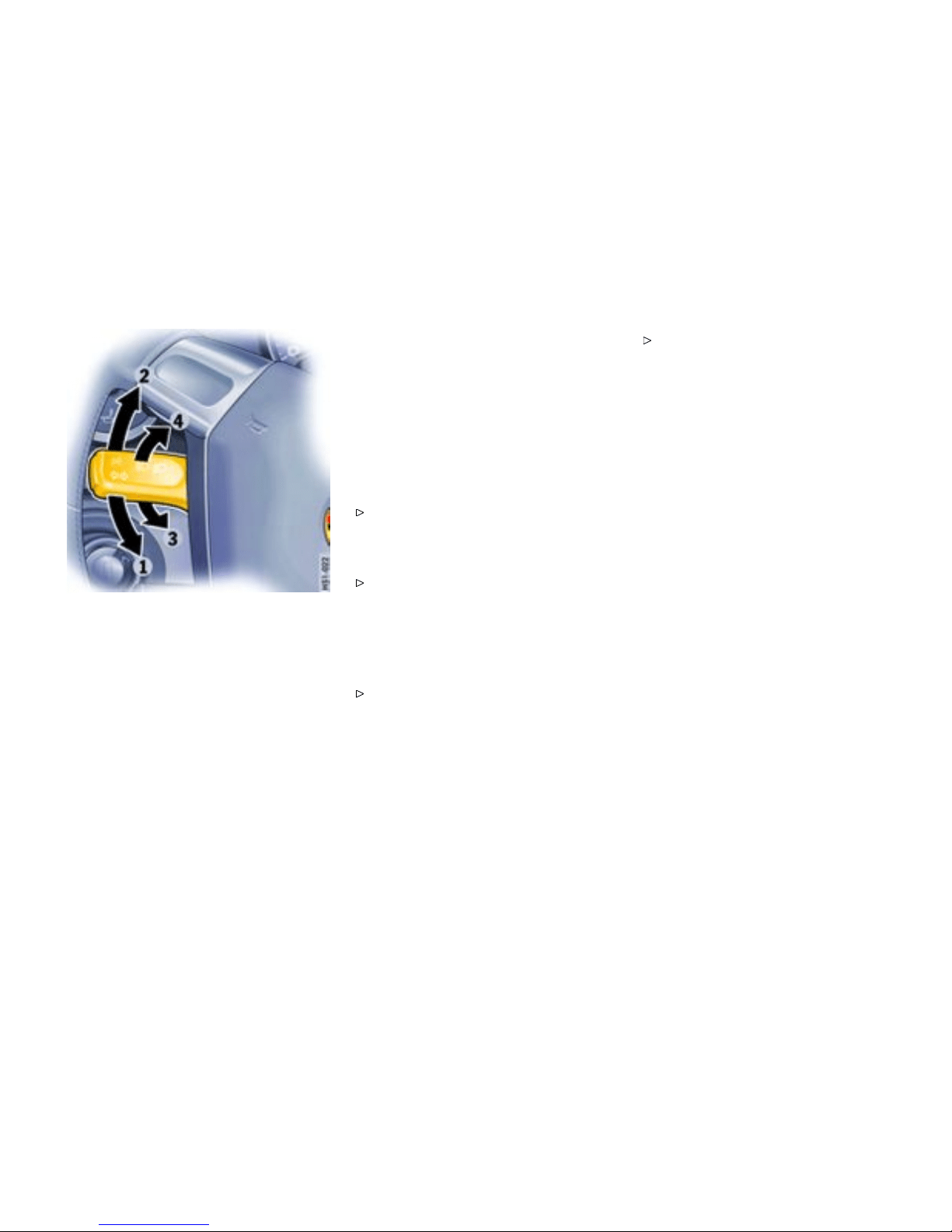
Turn Si gnal/ Head light
Dimmer/Pa rking light / Fla sher
Lever
Operation
Turn signals, low beam and high beam are ready
for operation when the ignition is on.
1 - Turn signal left
2 - Turn signal right
Push the lever to the upper or lower pressure
point - turn signals flash three ti mes
3 - High beam
4 - Headlight flasher
Lever in center position - Low beam
When high beam and headlight flashe r are select-
ed, the blue indicator light in the tachometer is lit.
The turn signal lever turns off automatically
when the steering wheel is straightened out after
completing a turn.
Lane ch anger
To indicate your intention when changing lanes
on the freeway, slightly lift or depress the lev er
to the resistance point. The lever will return to
the OFF position when released.
If the frequency of the display becomes
noticeable faster, check the operation of the
turn signal bulbs.
Headlight asher
(With ignition on or off)
To flash the h eadlights to oncomming motor-
ists, slightly pull the lever toward the steering
wheel and then release it. The blue indicator
light in the tachometer will go on/o ff as y ou
pull/release the lever.
Parking light
The parking light can only be switched on when the
ignition is switched off .
Move the lever up or down to switch on the
right or left parking light.
Controls, Instruments
149
Downloaded from www.ManualsFile.com manuals search engine
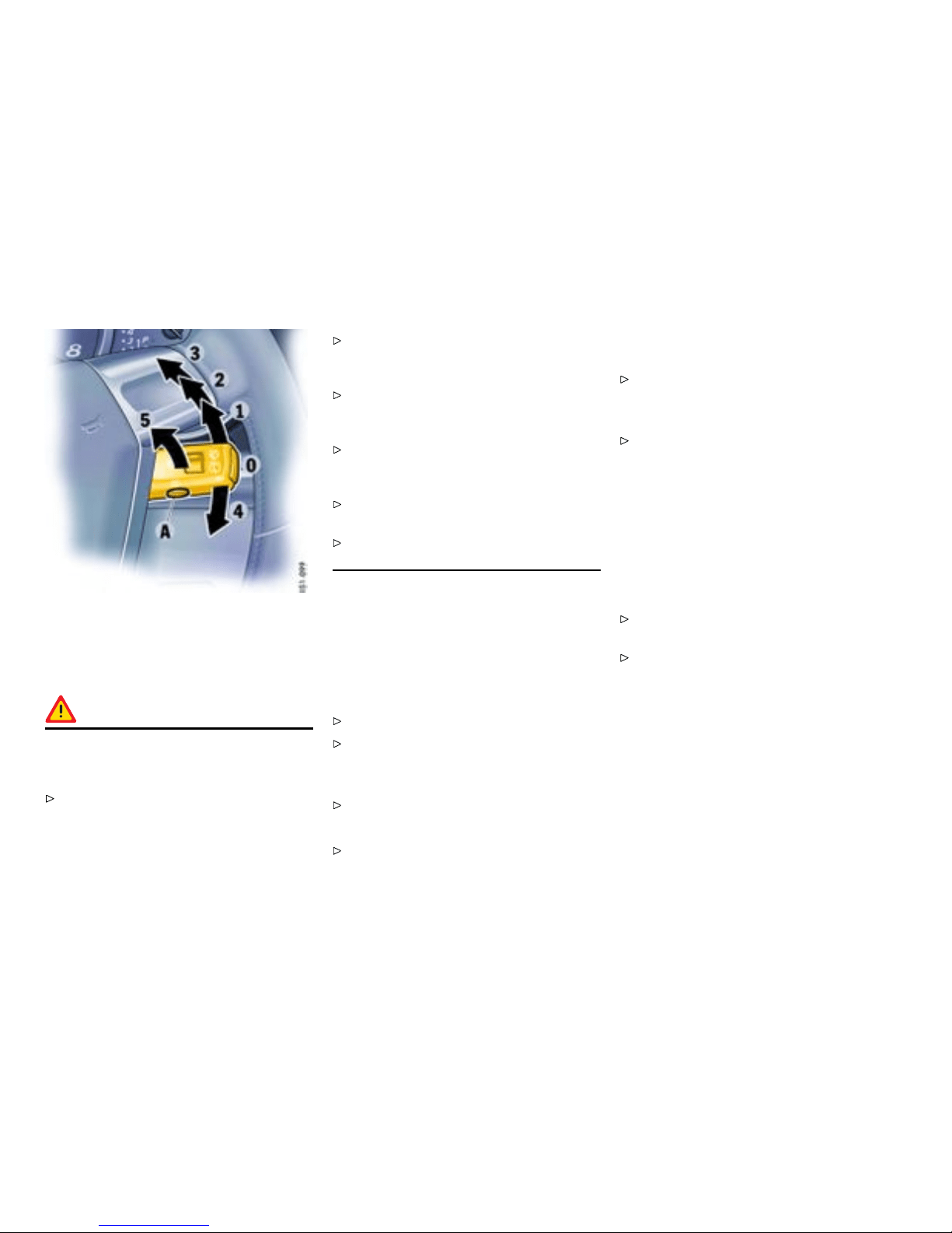
Windshield Wiper / Washer Lever
General information to the windshield
wipers
Warning!
Danger of injury when the windshield wipers
operate unin t entionally. Risk of damage to
the windshield and wiper system.
Avoid running the wiper blades over a dry
windshield to prevent scratching the glass.
Spray washer fluid on the windshield first. A
scratched windshield will reduce visibility.
Always loosen wiper blades from f rozen glass
before operating wipers to prevent damage to
the wiper motor or blades.
Always switch off windshield wipers in car
wash to prevent them wiping unintenti onally
(intermittent or sensor operation).
Always switch off windshield wipers before
cleaning the wi ndshield to avoid unintentional
operation (intermittent or sen sor operation).
Do not operate the headlight washer in car
washes.
Do not operate headligh t wash er when it is
frozen.
Front windshiel d wipers and headlight
washer system
0 – Windshi eld wipers off
1 – Intermittent/rain sensor operation for
front windshield wipers
Move wiper lever upwards to the first click.
Please observ e the chapter ”RAIN SENSOR” on
page 151.
2 – Windshi eld wipers slow
Move wiper lever upwards to the second click.
3 – Windshield wipers fast
Move wiper lever upwards to the third click.
4 – Front windshie ld wiper - one-touch opera -
tion:
Move wiper lever downwards. Th e windshield
wipers wipe once.
5 – Windshield wipers and washer system:
Pull wiper lever towards the steering wheel.
The washer system sprays and wipes while
the lever is pulled towards the st eering wheel.
When the wiper lever is releas ed, a few dryin g
wipes are executed.
A - Headlight washer (Vehicles with
Bi-Xenon headlights):
The washer sprays only while low beam or high
beam is switched on.
Briefly push button A to operate headlight
washer system.
If heavily soiled, repeat wash.
The headlight washe r system automatically sprays
once for every ten times the front windshield
washer system is operated.
Note
The windshield washer nozzles are heated when
the ignition is on, as a precaution against freezing.
150Controls, Instruments
Downloaded from www.ManualsFile.com manuals search engine

Wipe int erval control
Function
On vehicles without a rain sensor, the wiping
intervals can be adjusted in four steps.
Decreasing intervals
Adjust switch A upwards. The setting is
confirmed by one wipe of the windshield.
Increasing intervals
Adjust switch A downwards.
Rain sensor
In vehicles with a rain sensor the amount of rainfall
(snowfall too) which has settled on the windshield is
measured. Wiper speed is automatically adjusted
accordingly.
Switching on
Move wiper lever upwards to the first click.
Switching off
Move wiper lever to position 0.
The rain sensor remains switched off if the wiper
lever is already in position 1 wh en the ignition is
switched on.
To switch the rain sensor on again:
Move wiper lever to position 0 and then to
position 1 or
Operate windshield washer system 5 or
Change the sensitivity of the rain sensor with
four-sta ge switch A.
Switch -on is confirmed by one wipe of the wind -
shield .
On vehicles with the Sport Chrono Plus Package,
further rain sensor functions can be selected via
the PCM.
Please observe the chapter “Individu al
Memory” in the separate PCM operating
instructi ons.
Changing th e sensitivit y of the rain sensor
Sensitivity can be set with switch A in 4 stages:
Adjust switch A upwards - high sensitivity.
The setting is confirmed by one wipe of the
windshield.
Adjust switch A downwards - low sensitivity.
Maintenance note
Periodically clean the wiper blades with a w in-
dow cleaner, especially after the vehicle has
been washed in a car wash. We recommend
Porsche window cleaner. If they are ver y dirty
(e.g. with insect remains), they can be cleaned
with a sponge or cloth.
If the wiper blades rub or s queak, this may be as a
result of the following:
If the vehicle is washed in an automatic car wash,
wax residues may be adhering to the windshield.
These wax residues can be removed using a
window cleaner concentrate.
Please observe the chapter ”WASHER FLUID”
on page 223.
Please contact your authorized Porsche dealer for
further information.
The wiper blades may be damaged.
Replace damaged wiper blades as soon as
possible.
Controls, Instruments
151
Downloaded from www.ManualsFile.com manuals search engine
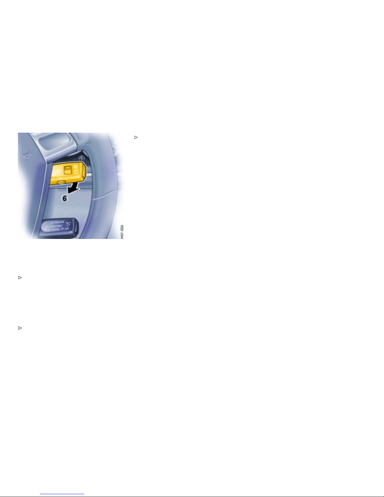
Rear wip er
6 – Rear window wiper - intermittent opera-
tion:
Move wiper lever forwards to the first click.
The rear window wiper wipes at preset
intervals.
The rear wiper is automatically switched off when
a speed of 130 mph (210 km/h) is exceeded. It
is switched on again when the speed falls below
118 mph (190 km/h).
On vehicles with the Sport Chrono Plus
Package , further rear wiper functions can
be selected via the PCM.
Please observe the chapter ”Individual
Memory“ in the separate PCM operating
instructions.
152Controls, Instruments
Downloaded from www.ManualsFile.com manuals search engine

A - Automatic speed control readiness off/on
1 - + SPEED/SET (accelera te/store)
2 - - SPEED (decelerate)
3 - OFF (interrupt)
4 - RES UME
Automatic Speed Control
Function
The automatic speed control maintain s any
selected speed between 15 mph and 145 mph
(30 km/h and 240 km/h) without you having to
use the accelerator pedal. The automatic speed
control is operated with the lever on the ste ering
wheel.
Warning!
Risk of an accident, resulting in serious
personal injury or death. A constant speed
may not be safe in heavy trafc, or on winding
or slippery roads. With the speed control
system engaged, the engine speed will not
return to idle when removing the foot from the
accelerator pedal.
Do not use the speed control when it may be
unsafe to keep the car at a constant speed.
Observe all local and national speed limits.
Vehicles with Tiptronic S
Additional downsh ifts are carried out to help
maintai n the pre-selecte d speed (especially when
driving downhill).
Switch automatic speed co ntrol readi ness
on
Press button A on the automatic speed control
lever.
This green in dicator light in the speedom-
eter now indicates readiness.
Hold and store speed
Bring the car to the desired speed with the
accelerator.
Then briefly push the operatin g lever forward
(position 1).
Controls, Instruments
153
Downloaded from www.ManualsFile.com manuals search engine

Acceler ating (e .g. to overtake)
Option 1
Increase the speed as usual with the acceler-
ator. When you ease off the accelerator, the
previously saved value is set again.
Option 2
Push operating lever forward (position 1) until
the desired speed is reached. The speed
reached is maintained and stored when the
lever is released.
Option 3
Push lever slightly forwards (position 1)
(a maximum of 10 times). The speed is
increased by 1 m p h (1.6 km/h) each time.
Note on operation
Speed control operation is automaticall y interrupt-
ed if the speed is increased by more than approx.
16 mph (25 km/h) for longer than 20 seconds.
Decelerating
Option 1
Pull operating lever towards the steering wheel
(position 2) until the desired s peed is reached.
The speed reached is maintained and stored
when the lever is released.
Option 2
Briefly move lever towards the steering wheel
(position 2) (a maximum of 10 times). The
speed is reduced by 1 mph (1.6 km/h) each
time.
Vehicles with Tiptron ic S
Additional downshifts are carried out to imp rove
deceleration (especial ly when driving downhill ).
Interrupting automatic speed contro l
operation
Manual in terruption
Pull operating lever downwards briefly
(position 3) or
Operate brake or c lutch pedal or
Switch Tiptronic transmission to selector lever
position N.
Please observe the chapte r ”TIPTRONIC S” on
page 195.
The speed driven before the interruption remains
stored in the memory.
Automatic speed control operation is
interrupted automatically:
– If the set vehicle speed is exceeded by more
than approx. 16 mph (25 km/h) for longer than
20 seconds.
– If the actual vehicle speed falls to approx.
6 mph (10 km/h) below the set vehicle speed
for longer than 5 seconds (upward s lopes).
– For PSM control operations.
Resuming the stored speed
Briefly push operating lever upwards (position
4). The speed control accelerates/deceler-
ates the vehicle to the stored speed.
154Controls, Instruments
Downloaded from www.ManualsFile.com manuals search engine

The stored speed should only be recalled when
traffic conditions and the road surface so permit.
Switching autom atic speed control
readiness off
Press button A on the automatic speed
control lever. The green readiness light i n
the speedometer goes off.
When the vehicle is parked and the ignition
switched off, the memory is cleared.
Note
On upward o r dow n ward slopes, the set speed
cannot always be maintained by the automatic
speed control.
To obtain sufficient engine braking or a better
engine -speed range, therefore, you have to select
a lower gear.
Controls, Instruments
155
Downloaded from www.ManualsFile.com manuals search engine
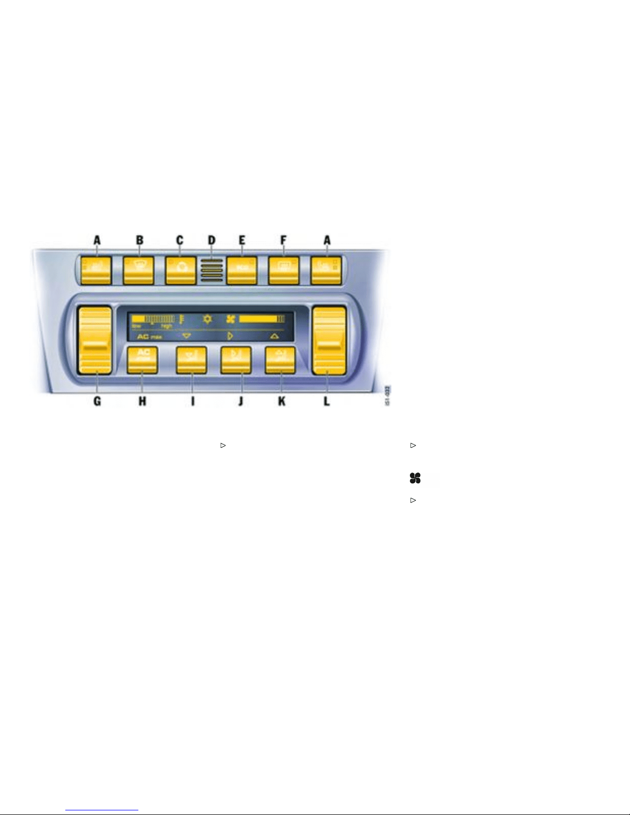
A - Seat heating
B - Defrosting the windshield
C - Recirculating -air button
D - Tempe rature sensor
E - ECO button (air-conditioning compressor
off/on)
F - Heated rear window
G - Temperature butt on
H - AC max
I - Air distribution to footwell
J - Air distribution to central and side vents
K - Ai r distribution to windshield
L - Blower speed butto n
Air conditioning
The display panel shows the following
Air quantity, air distribution, and temperature can
be set on the control panel.
– Temperature
– Air-conditioning compressor on/off
– Blower speed
– AC max
– Air distribution
Setting temperature
Press button G upwards or downwards
respectively.
The selected temperature is shown on the display
by a bar display.
If a bar cannot be seen, the temperature is set to
maximum cold.
If all bars can be seen, the temperature is set to
maximum warm.
Note
For maximum cooling, activate AC max button
H.
Adjust ing blower speed
Press button L upwards or downwards
respectively.
The blower speed is shown on the d isplay by a bar
display.
The compressor is switched off at low blower
speeds.
156Controls, Instruments
Downloaded from www.ManualsFile.com manuals search engine
Defrosting the wi ndshield
Press button B (switch on or off). The light-
emitting diode in the button lights up. The
windshie ld is demisted or defrosted as quickly
as possible. Air flows to the windshield only.
Recirculating-air setting
Function
The outside-air supply is int errupted and only the
inside air is circulated.
Warning!
Risk of accident due to impaired vision,
resulting in serious personal injury or death.
In recirculating-air setting, the windows may
fog up.
Only select recirculating-air setting for short
periods.
If the windows fog up, switch recirculating-air
setting off immed iately by pressing the
recirculating-air button again and select the
“Defrost windshield” function.
Switching circulating-air mode on or off
Press circula ting-air button C. The light-
emitting diod e in the button lights up.
ECO - switching the air-condit ioning
compressor on and off
The air conditioning compressor switches off
automa tically at temperatures below approx.
37°F /3°C and cannot be switched on, even
manually.
Whenev er outside temperatures exceed approx.
37°F /3°C , the air-conditioning compressor can
be switched on or off manually.
The compressor can be switched off manua l to
save fuel.
Press ECO button E. The light-emitting di ode
in the button lights up. The compressor is
switche d off.
If the interior temperature is too high, switch
on the compressor again.
To dry incoming air in damp weather, do not switch
off the air-conditioning compressor. This prevents
misting of windows.
AC max operation
In AC max operation, the interior of your vehicle is
cooled as quickly as possible.
Press AC max button H. The light-emitting
diode in the button lights up.
Controls, Instruments
157
Downloaded from www.ManualsFile.com manuals search engine

Air distri bution
Settings
The individual air distributions can be combined
as desired. If an air distribution is not selected, no
symbol appears in the display panel. Air flows then
from all vents as well as to th e windshield.
Recommended setting in Summer - Air distributio n
to central and side vents
Recommended setting in Winter - Air distribution to
footwell a nd windshield
Air distribution to footwell
Press button I. The selection appears on the
display panel. The air flows to the footwell.
Air distribution to center and side
vents
Press button J. The selection appears on the
display panel. The air flows from the central
and side vents. Vents must be open.
Air distribution to windshield
Press button K. The selection appears on the
display panel . The air flows to the windshield.
Information on air-conditioning
compressor
– May switch off briefly to ensure sufficient
engine cooling if the engine is operating under
extreme load.
– Opera tes most effectively with the windows
closed. If the v ehicle has been in the sun for
a long time, it is a good idea to ventilate the
interior briefl y with the windows ope n.
– Depending on the outside temperature and
humid ity, condensation can drip from the
evaporator and form a pool under the car. This
is normal and not a sign of leakage .
– If uncooled air flows out when the lowest
tempe rature has bee n set, switch off the air
conditioning compressor and have the fault
remedied. Please contact your authorized
Porsche dealer for fu rther information.
158Controls, Instruments
Downloaded from www.ManualsFile.com manuals search engine
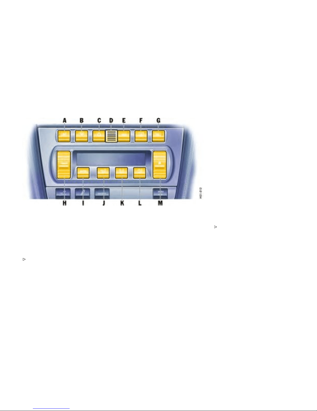
A - Seat heating, left
B - Defrosting the windshield
C - Recirculating -air button
D - Temperature sensor
E - ECO button (air-conditioning compressor
off/on)
F - Heated rear window/door mirror heating
G - Seat heater, right
H - Temperature button
I - AUTO button (automatic mode)
J - Air distribution to footwell
K - Air distribution to central and side vents
L - Air distribution to windshield
M - Blower speed button
Automatic air conditioning system
Automatic mode
The automatic air-condition ing system controls
the preselected interior temperature completely
automatically. If necessary, the autom atic system
can be manually influenced.
Press AUTO button I. AUTO will appear on the
display panel. Air quantity and distributio n are
automatically controlled and variations are
compensated.
All automatic setting functions can be individual ly
changed. This sett ing is retaine d until the appropri-
ate function button is pressed again or the AUTO
button is pressed.
Setting t e mperature
Press button H upwards or downwards
respectively.
To suit personal comfort, the interior tem-
perature can be adjusted between 61°F and
85°F /16°C and 29.5°C .
Recom mendation: 7 2F/22C.
If “LO” or “HI” appears on the display, the system is
operating at maximum cooling or heating power.
Automatic control is no longer active.
Controls, Instruments
159
Downloaded from www.ManualsFile.com manuals search engine
Note
If the preselected temperature is c hanged, the
blower speed can increase automatically in
automatic mode. The desired temperatu re is
reached more quickly this way.
Sensors
To avoid affecting the performan ce of the air-condi-
tioning system:
Do not cover the su n sen sor on t he instrument
panel or the temperature sensor D.
Defrosting the windshield
Press button B (switch on or off). The wind-
shield is demisted or defrosted as quickly as
possible . Air flows to the wi ndshield only. The
light-emitting diode in the button lights up.
ECO - switching comp ressor for
air-conditionin g system on and off
The air conditioning compressor switches off
automatically at temperatures below approx.
37°F /3°C and cannot be switched on, even
manually.
Whenever outside temperatures exceed approx.
37°F /3°C , the air-conditioning compressor is
always switched on in automatic mode.
The compressor can be switched off manually to
save fuel, but control comfort is then limited:
Press ECO button E. The compressor is
switched off. The light-emitting diode in the
button lights up.
If the interior temperature is too high, switch
compressor back on or press AUTO button.
To dry in coming air in damp weather, do n ot switch
off the air-conditioning compressor. This preven ts
misting of windows.
Adjusting blower speed
Press button M upwards or downwards
respectively. The preset blower speed is
increased or decreased.
The speed stages are indicated by a bar display.
The compressor is switched off at low blower
speeds.
If the button is pressed downwards at the lowest
blower stage, the blower and automa tic control are
switched off. “OFF” will appear on the display field.
Pressing the button upwards or pressing the AUTO
button switches the blower and automatic control
back on again.
Recirculating -air setting
Function
The outside-air s upply is interrupted and only the
inside air is circulated.
Warning!
Risk of acciden t due to impaired vision,
resulting in serious personal injur y or death.
In recirculat ing-air setting, the windows may
fog up.
Only select recirculating-air setting for short
periods.
If the windows fog up, switch recirculating-air
setting off immediately by pressing the
recirculating-air button again and select the
“Defrost windshield” function.
Switching recirculatin g-air setting o n or off
Press button C. The light-emitting diode in the
button lights up.
Over approx. 37F/3°C
If the air-conditioning compressor was off, it
switche s on automatically. The duration of
recirculating-air setting is not limited.
160Controls, Instruments
Downloaded from www.ManualsFile.com manuals search engine

Below approx. 37F/3°C
The air-conditi oning compressor is switched off.
Recirculating -air setting is automatically ended
after approx. 3 minutes.
Air distribution
Settings
The individual air distributions can be combine d as
desired.
Recommended setting in Summer - Air distribution
to central and side vents
Recommended setting in Winter - Air distribution to
footwell and winds hield
Air distribution to footwell
Press button J. The air flo ws to the footwell.
The selection appears on the di splay panel.
Air distribution to center and side
vents
Press button K. The air flows from the central
and side vents. Vents must be open. The
selection appears on the display panel.
Air distribution to windshield
Press button L. The air flows to the windshiel d .
The selection appears on the di splay panel.
Note on operation
On vehicles with the Sport Chrono Package
Plus, individual air conditioning settings can
be stored on your car key. Please observe the
chapte r “Individual Memory” in the separate
PCM operating instructions.
Inform ation on air-conditioning
compressor
– May switch off briefly to ensure sufficient
engine coolin g if the engine is operating under
extreme load.
– Opera tes most effectively with the windows
closed. If the vehicle has been in the sun for
a long time, it is a good idea to ventilate the
interior briefly with the windows open.
– Depending on the outside temperature and
humid ity, condensation can drip from the
evapor ator and form a pool under the car. This
is normal and not a sign of leakage.
– If uncooled air flows out when the lowest
temperature has been set, switch off the air
conditioning compressor and have the fault
remedied. Please contact your authorized
Porsche dealer for further information.
Controls, Instruments
161
Downloaded from www.ManualsFile.com manuals search engine
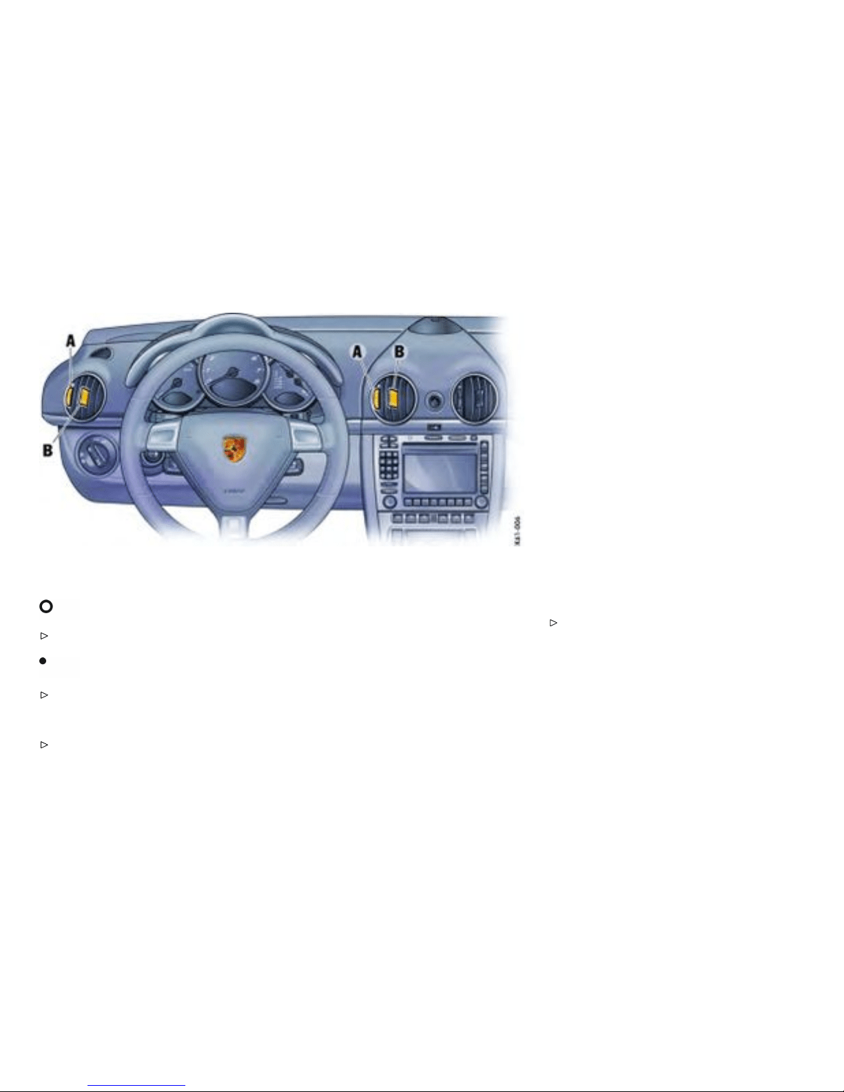
A - Continuous opening and closing
B - Setting vent direction
Central and side vents
Opening vents
Rotate thumb wheel upward.
Closing vents
Rotate thumb wheel downward.
Changing air ow direction
Swivel the vent fins in the desired direction.
Outsid e air or conditioned air can be delivered from
all vents depending on the air-distribution setting
on the operating panel.
Fresh-air intake
In order to ensure unhindered air intake:
Keep the fresh-air intake between the wind-
shield and the luggage compartment lid free
from snow, ice and leaves.
162Controls, Instruments
Downloaded from www.ManualsFile.com manuals search engine
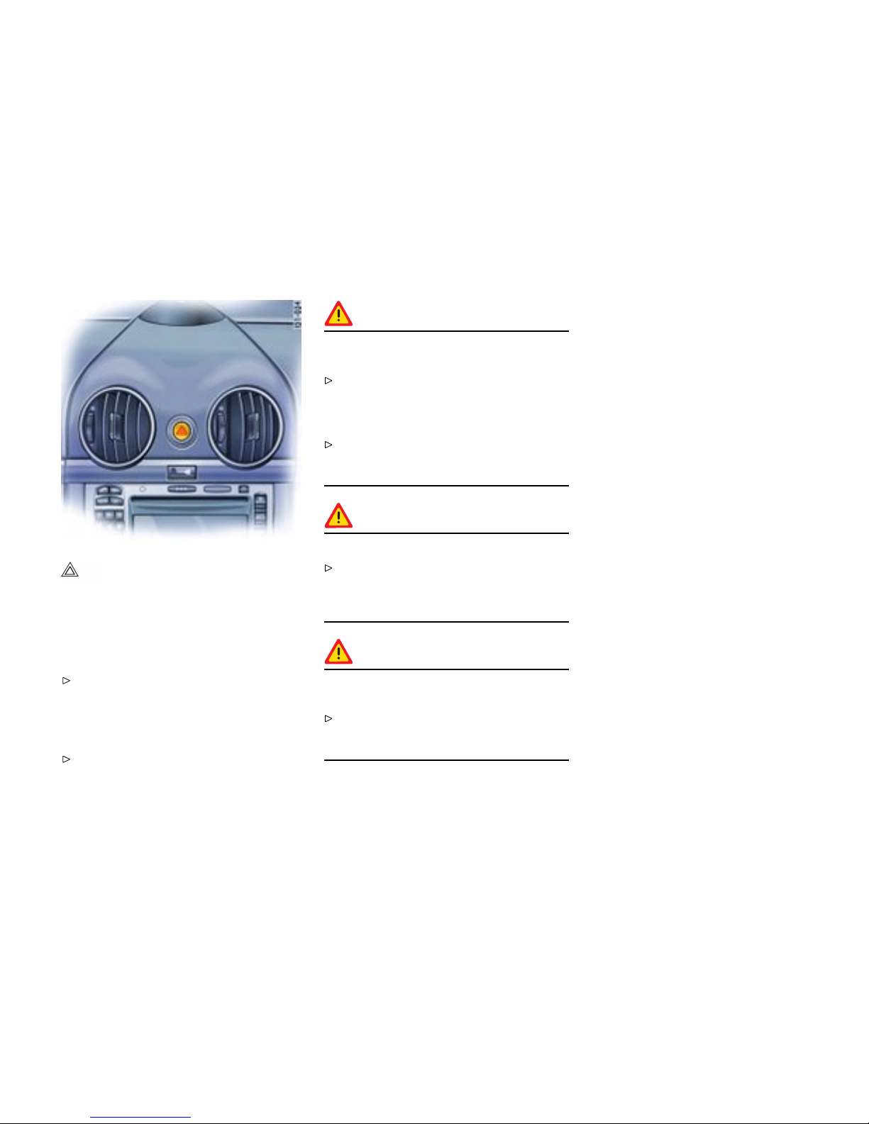
Emergenc y Flasher Switch
Switching on and off
Operational readin ess of the emergency flasher
does not depend on the ignition lock and turn signal
lever position .
If your car is disabled or parked under emer-
gency conditions switch on the emergency
flasher in the dashboard. All turn signals and
the indicator light in the switch flash with the
same frequency.
Press button.
Warning!
Risk of accident, resulting in serious pers onal
injury or death.
Wheneve r stalled or stoppe d for emergency
repairs, move the car well off the road. Switch
on the emergency flasher and mark the car
with road flares or other warning devices .
Do not remain in the car. Someone approach-
ing from the rear may not realize your vehicle
is stopped and cause a collision.
Warning!
Danger of re.
Do not park or operate the vehicle in areas
where the hot exhaust system may come in
contact with dry grass, brush, fuel spill or
other flammable material.
Warning!
Hot engine compartment components can
burn skin on contact.
Before working on any part in the engine
compartment, turn the engine off and let it
cool down sufficiently.
Controls, Instruments 163
Downloaded from www.ManualsFile.com manuals search engine
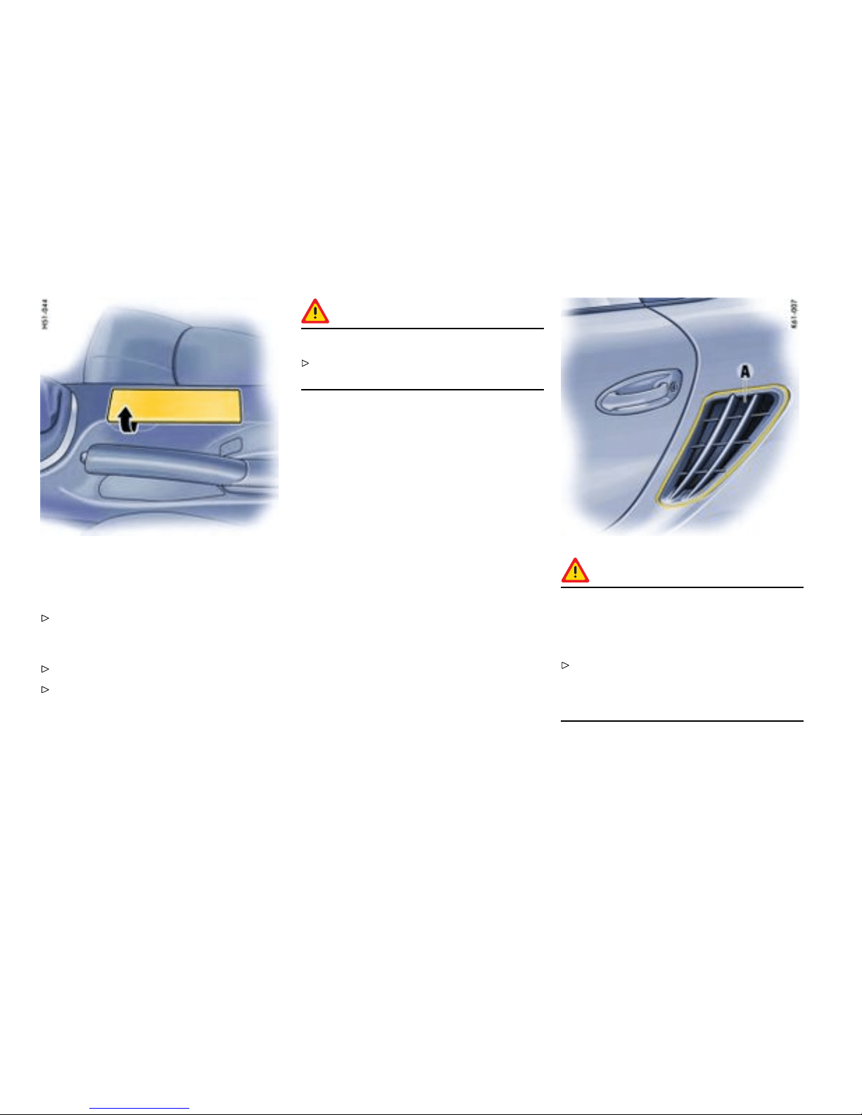
Ashtray
Opening
Open ashtray lid.
Emptying
Open ashtray and carefully pull out ash insert .
Leave ashtray lid open. Push in ash insert.
Warning!
Danger of re.
Never use ashtray for waste paper disposa l,
as it could pose a fi re hazard.
Danger!
Dange r of re in engine compartment due
to burning cigars or cigarettes. Serious
personal injury or death could result from
re i n the engine compartment.
Do not throw any lit cigars or cigarettes out
of the vehicle. T h ey can be blown into the air
inlets A by the air flow and cause a fire in the
engine compartment.
164Controls, Instruments
Downloaded from www.ManualsFile.com manuals search engine

Cigarette Lighter
Warning!
Dange r of re and burning. The cigarette
lighter is ready for use, regardless of the
ignition lock posi tion.
Never leave unsup ervised children in the car.
Never touch the heating element or sides of
the lighter.
Hold the lighter by the knob only.
Heating lighter
Open ashtray lid.
Push in knob of the cigarette lighter. When
ready f or use, the lighter will snap back.
Note on operati on
The lighter receptacle is not to be used for
electrical accessories (excep t for the tire filling
compressor).
Please observe the chapter ”SOCKETS” on
page 166.
Controls, Instruments
165
Downloaded from www.ManualsFile.com manuals search engine
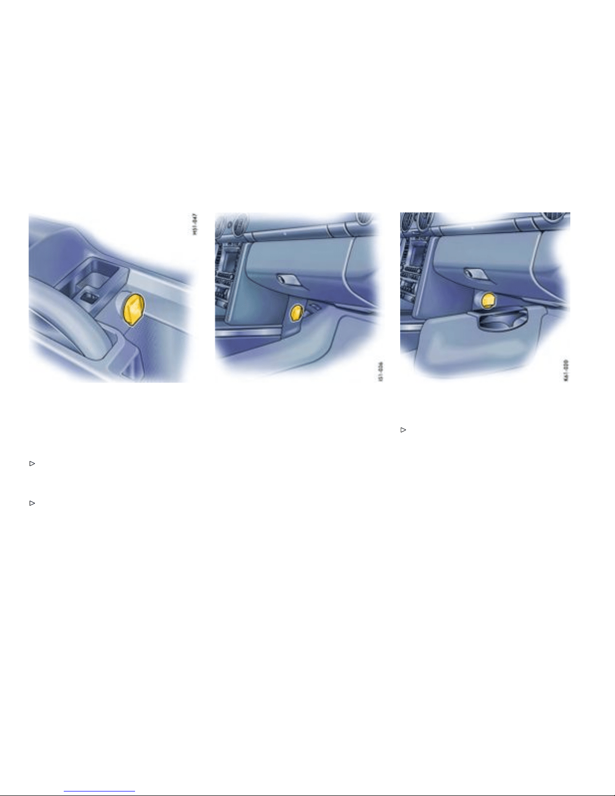
In storage tray between the seats
Sockets
Electrical accessories should preferably be
connected to th e 12 V sockets.
Please obse rve the maximum power consu mp-
tion.
Note on operation
The tire filling compressor must be connected
to the cigarette lighter.
In the passenger’s footwell
Note on operation
The sockets and thus the connected electrical
accesso ries will function even if the ignition is
switch ed off or the ignition key is withdrawn.
If the engine is not running and the accessories are
switched on, the vehicle batter y will be discharged.
Do not operate additional accessories for more
than 5 minutes when engine is off. Continuing to
do so may drain the battery such that it may go
completely dead.
Maxim um power consumption for both
sockets together: 70 W.
In the passenger’s footwell with Bose Surround
Sound-System
Please observe the power specifications from
the accessory manufacturer.
166Controls, Instruments
Downloaded from www.ManualsFile.com manuals search engine
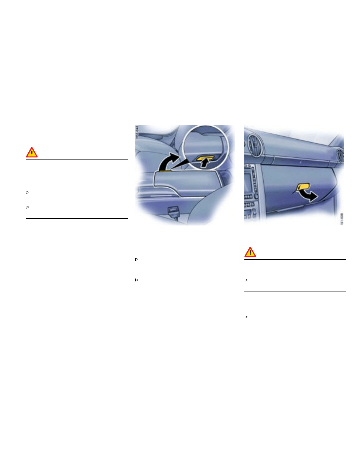
Storage in the passenger
compartme nt
Warning!
Unsec ured luggage and heavy objects may
come loose durin g braking, rapid directional
changes or in an accident and cause serious
personal injury or d eath.
Do not carry items of lu ggage or objects in the
passenger compartment unsecured.
Do not transport any heavy objects in the
oddments trays.
Additional storage possibilities
– in the doors,
– in the d oor sill next to the passenger’s seat,
– in the center console,
– clothes hook on back of seat backrest,
– oddments tray with coin holder between seats,
– glove compartment with C D and pen holder,
– side storage compartments behind the seats.
Oddments tray be tween the seats
Opening
Press release button and lift the lid. There is a
coin holder and socket in the forward part of
the oddments tray.
Please observe the chapter ”SOCKETS” on
page 166.
Glove compartm ent
Warning!
Danger of injury by the glove compartment lid
in case of an accident.
Keep the glove compartment lid closed while
driving .
Opening
Pull the catch and open the lid.
Controls, Instruments
167
Downloaded from www.ManualsFile.com manuals search engine
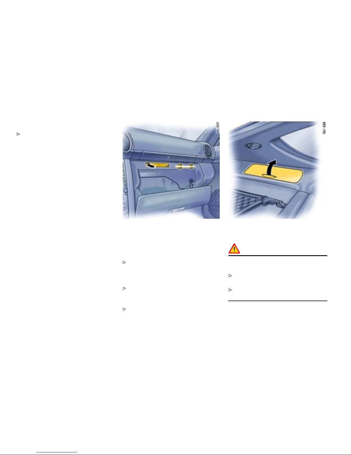
Locking
Lock the catch to secure the contents against
unauthorized access.
CD holder
Occupied drawers are indicated by a red window.
Opening drawers
Push the button of the drawer you wish to
open.
Closing d rawers
Fold up drawer and close until it engages.
Pen holder
A pen can be clipped in on the right side of the
CD holder.
Side storage compa rtments behind th e
seats
Warning!
Danger of injury during braki ng, rapid direc-
tion changes or in an accident.
Do not carry items of luggage or objects in the
passenger compartment unsecured.
Do not transport any heavy objects in the
oddments trays.
168Controls, Instruments
Downloaded from www.ManualsFile.com manuals search engine

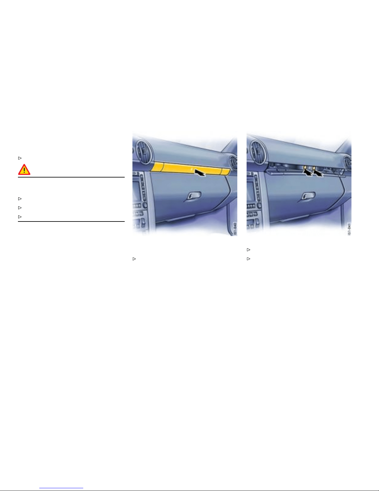
Cupholder
Holder for d rinks cans and cups
Keep the cupholder closed while driving.
Warning!
Risk of scalding or damage due to spilling
drinks.
Only use beverage contai n ers which fit.
Never put overfull containers in the cupholder.
Never use hot drinks.
Extending cupholder
Press the panel. The panel opens.
Press the symbol for the respec tive cupholder.
Close panel in the middle.
170Controls, Instruments
Downloaded from www.ManualsFile.com manuals search engine
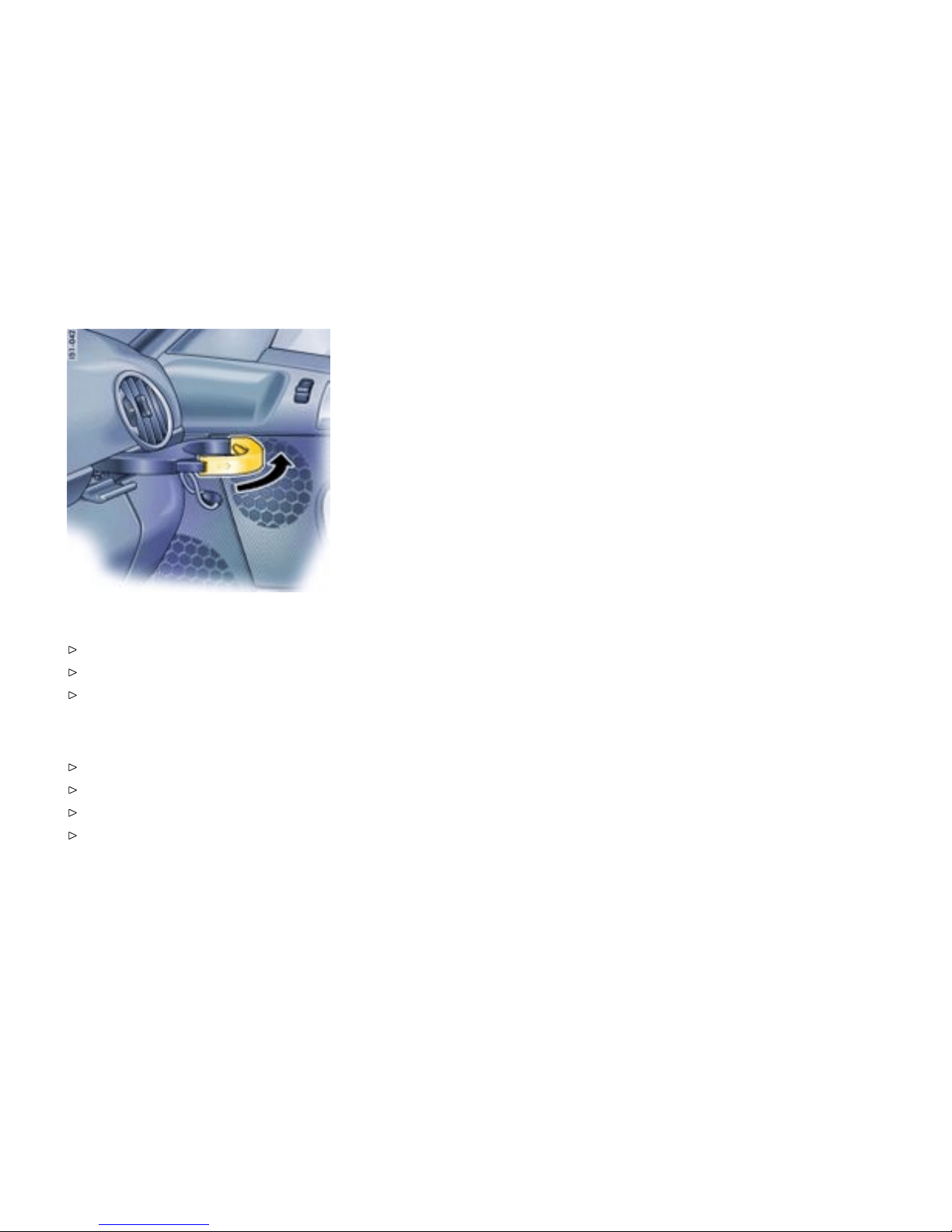
Pulling cupholder out
Pull out holder (arrow).
Insert container.
Carefully slide holder inwards t o adjust it to the
container size.
Closin g cupholder
Push cupholder drawer in.
Open panel in the middle.
Close and engage the cuphol d er.
Close panel in the middle.
Controls, Instruments
171
Downloaded from www.ManualsFile.com manuals search engine
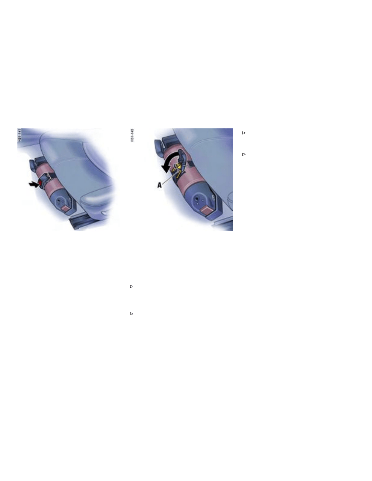
Fire ext inguisher
Taking out re extinguisher
In cars with a fire extinguisher, the extinguisher is
fitted to the front of the driver’s seat.
1. Hold fire exti nguisher with one hand and press
the PRESS button on the fastening strap with
the other hand (arrow).
2. Remove fire e xtinguish er from mounting.
Inser t ing re extinguisher
1. Place fire extinguisher in the mounting.
2. Engage fastening strap lug A in the tension
jack and close tension jack (arrow).
Note
Pay attention to the expiration date on the fire
extinguisher. If the fire ext inguisher is used
after its expiration date has elapsed, it may not
function properly.
Follow the operatin g instru ctions for the fire
extinguisher.
The functional ability of the fire extinguisher
should be checked by a specialist workshop
every 1 - 2 years.
After use, have the fire extinguisher refilled.
172Controls, Instruments
Downloaded from www.ManualsFile.com manuals search engine
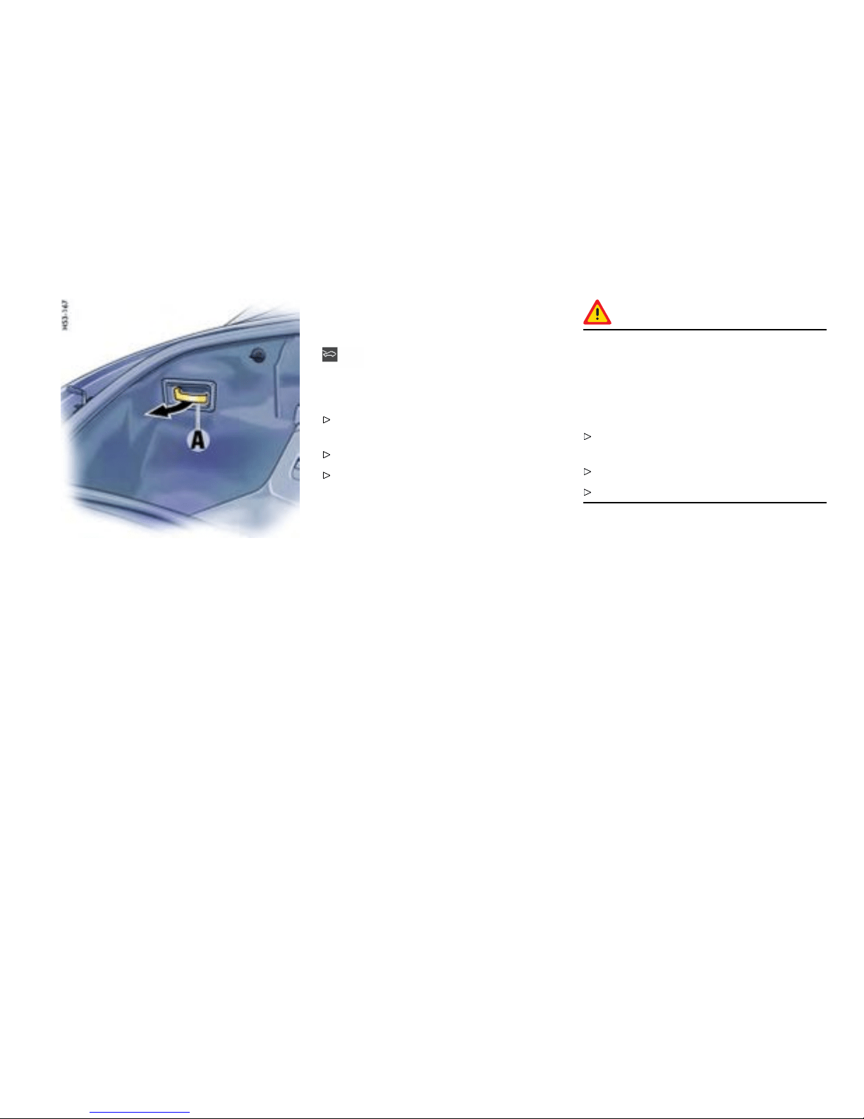
Front luggage compartment
Trunk E ntrapment
Your vehicle is e q uipped with an internal front trunk
release mechanism.
A person trapped in the f ront luggage compart-
ment can release the lid from the insid e using
unlockin g handle A.
The handle A is fluorescent and glows in the dark.
Note
When loading the luggage compartment, make
sure that items of luggage or other objects cannot
become caught on handle A. This could cause the
luggag e compartment to open unintentionally.
Warning message
A warning message in the on-board co mputer
lights up when unlocking handle A is operated.
Stop the vehicle immediately when the warning
message lights up.
Check the luggage compartment.
Close the lid.
Function with vehicle stationary
If the luggage compartment lid is unlocked with
unlocki ng handle A, the lid can be opened from the
inside immediately.
Function with vehicle in motion
If the luggage compartment lid is unlocked with
unlocki ng handle A when a speed of 2 mph
(3 km/h) is exceeded, the warning message in
the on-board computer lights up. At the same time,
the lid is un locked and the latch striker pops into
the catch-hook position.
Danger!
Risk of accident. If the warning message in
the on-board compu t er lights up when the
vehicle is in motion, the lid may impact in
front of the windshield and can tear off. You
can lose control of the vehicle, and serious
personal i njury or death may result.
Stop the vehicle immediately when the warning
message lights up.
Check the luggage compartm ent.
Close the lid.
Note
The front lid cannot be opened from the inside if the
battery is disconnected or empty.
Safety reasons therefore require that you
unscrew the latch striker of the front lid lock if
you plan to put the vehicle out of operatio n for
an extende d peri od.
Please consult your authorized Porsche dealer.
They will advise you about the necessary meas-
ures.
Controls, Instruments
173
Downloaded from www.ManualsFile.com manuals search engine
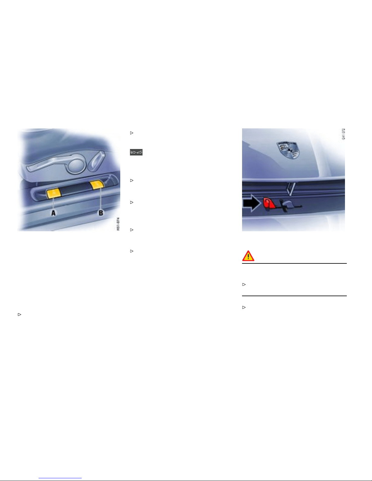
A - Opening front luggage compartment lid
B - Opening rear lu ggage compartment lid
Front L uggage Compartment lid
Gener al information
Note
If the vehicle battery is discharged, the front lid can
be opened only by connecting an external electrical
power source.
Please observe the ch apter ”EMERGENCY
UNLOCKING OF THE FR ONT LUGGAGE
COMPARTMENT LID” on p age 260.
Please obser ve the description inside the fuse
box lid.
Warning message
A warning message in the on-board computer
comes on if the lids are not completely closed.
Fully close the lid.
Unlocking the lid
Operate pull-button A next to the driver’s
seat or corresponding button of the remote
control. When the li d is open, the luggage
compartment is lit.
Please observe the chapter ”LOAD SWITCH-
OFF AFTER 2 HOURS OR 7 DAYS” on page
259.
Please observe the c hapter ”KEY WITH RADIO
REMO TE CONTROL” on page 23.
Opening front luggage compartment lid
Caution!
Risk of damage to luggage compartment lid
or windshiel d wipers.
Make sure t hat the windshiel d wipers are not
folded out forwards when opening the lid.
Raise lid slightly and unlatch the safety catch
with the lever (arrow).
174Controls, Instruments
Downloaded from www.ManualsFile.com manuals search engine

Closing front and rear luggage
compartment lid
Lower the lid and close it.
Push the lid closed with the palm of your hand
in the area of the lock. Check that the lid has
correctly engaged in the lock.
Warning!
Risk of loss of control or an accident, resu lting
in serious personal injury or de ath.
Should you notice at any time while driving that
one of the lids is not secured properly, please
stop immediately in a suitable place and close
it. Th e front lid may fly up impairing vision.
Controls, Instruments 175
Downloaded from www.ManualsFile.com manuals search engine
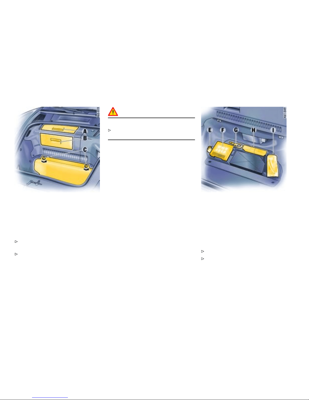
Front L uggage Compartment
Access covers
(on vehicles with DVD navigation or CD changer)
Opening
Grasp access cover A or B at the handle and
open.
The drive for DVD navigation and the CD
changer can be found behi nd the access cover
B.
Caution!
Risk of damage.
Do not store any heavy, damp or h eat-sensitive
objects behi nd the access covers.
E - Adapter for security wheel bolts
F - Tire lling compressor
G - Towing hook
H - Tool kit
I - Tire se alant
Tool box
Opening
Unlock turn-lo cks C.
Open tool box and place it on the floor of the
luggage compartment.
176Controls, Instruments
Downloaded from www.ManualsFile.com manuals search engine

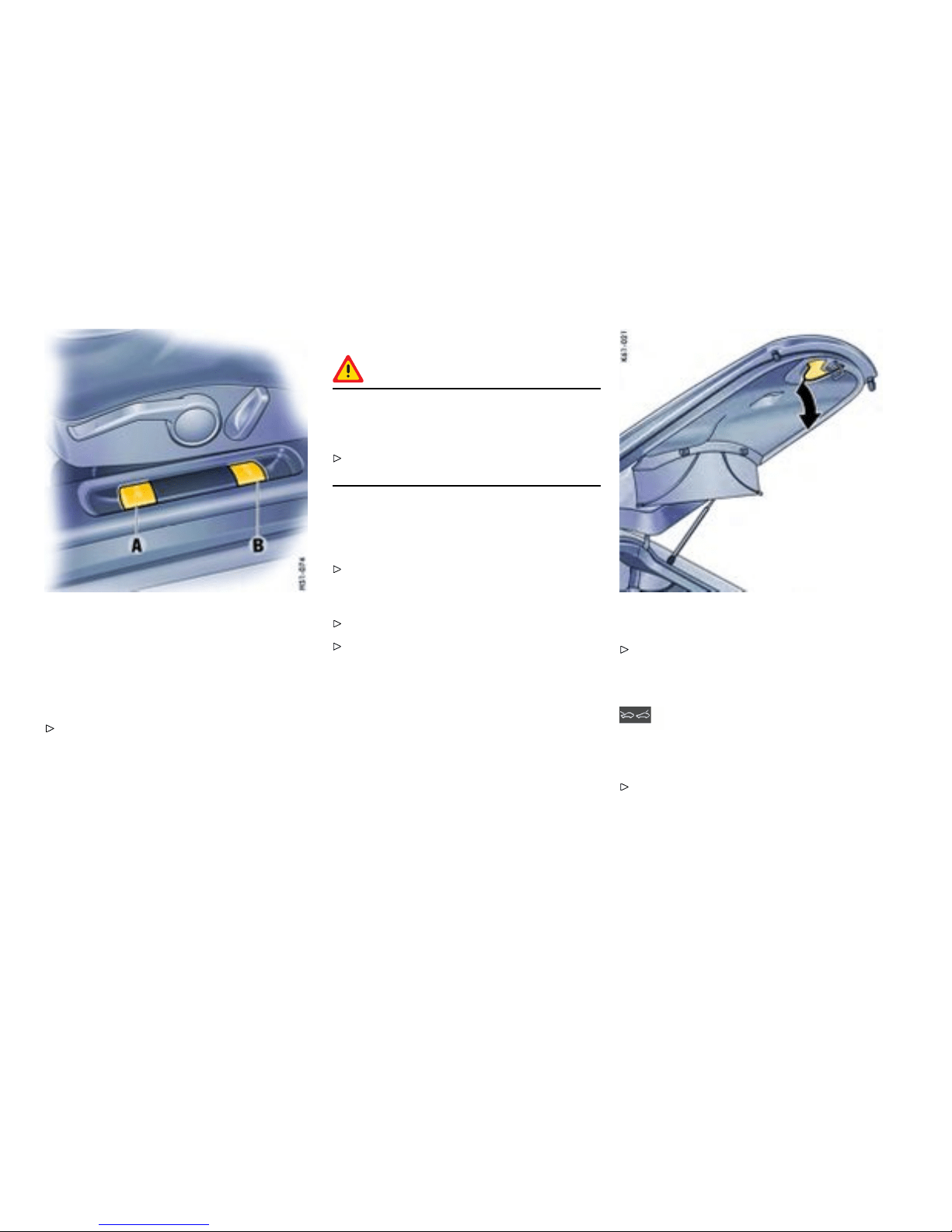
A - Opening front luggage compartment lid
B - Opening rear lu ggage compartment lid
Rear Lid
Releasing the rear lid
Operate pull-button B next to the driver’ s seat
or corresponding button of the remote control.
Opening the rear lid
Caution!
Risk of damage to the paint on the rear lid if
this touches the load transp ort ed on the roof
rack when opening.
Only open the rear lid if this cannot touch the
load.
The rear lid can be held open in 2 positions. Th e
luggage compartment is illuminated when the
respective lid is open.
Please observe the chapter ”LOAD SWITCH-
OFF AFTER 2 HOURS OR 7 DAYS” on page
259.
Position 1: Raise rear lid up to pressure point.
Position 2: Raise rear lid beyond the pressure
point.
Closing the rear lid
Pull down the rear lid on the handle and allow it
to fall into the lock. Check that the rear lid has
correctly engaged in the lock.
Warning message
A warning message in the on-board computer
comes on if the lids are not completely closed.
Fully close the lid.
178Controls, Instruments
Downloaded from www.ManualsFile.com manuals search engine

A - Topping up engine oil
B - Checking coolant l evel or topping up
Rear luggage compartment
Service ap
Press catch button on the service flap and
open flap.
Luggage net, tie-d own rings
Warning!
Unsecured luggage and heavy objects may
come loose during braking, rapid directional
changes or in an accident and cause serious
personal injury or death.
Do not carry items of lu ggage or objects in the
passenger compartment unsecured. Secure
load against sliding.
Do not transport heavy objects under the
luggage net.
Hang the luggage net on the 4 tie-down rings
around the engine cover or in th e rear luggage
compartment.
Controls, Instruments
179
Downloaded from www.ManualsFile.com manuals search engine
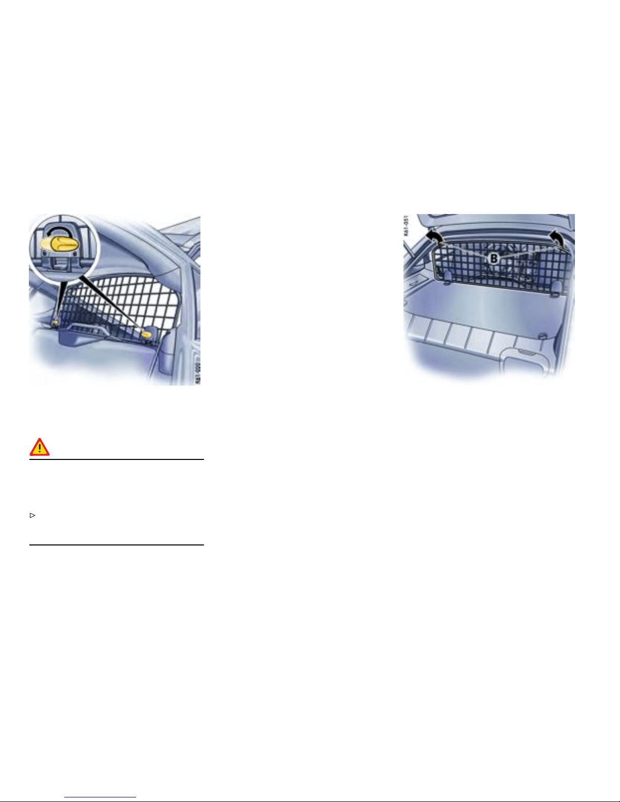
Cargo partition
Removing th e cargo partition
Warning!
Unsecu red luggage and heavy objects may
come loose during braking, rapid directional
change s or in an accident and cause serious
personal injury or death.
Do not carry items of luggage or objects in the
passenger compartment unsecured. Secure
load against sliding using the cargo partit ion.
1. Turn both turn-locks to ”Lock open“ from the
passenger compartment .
2. Lift the cargo parti t ion somewhat from the
luggage com part m ent and disengage on both
sides from the upper hooks B and hold.
180Controls, Instruments
Downloaded from www.ManualsFile.com manuals search engine
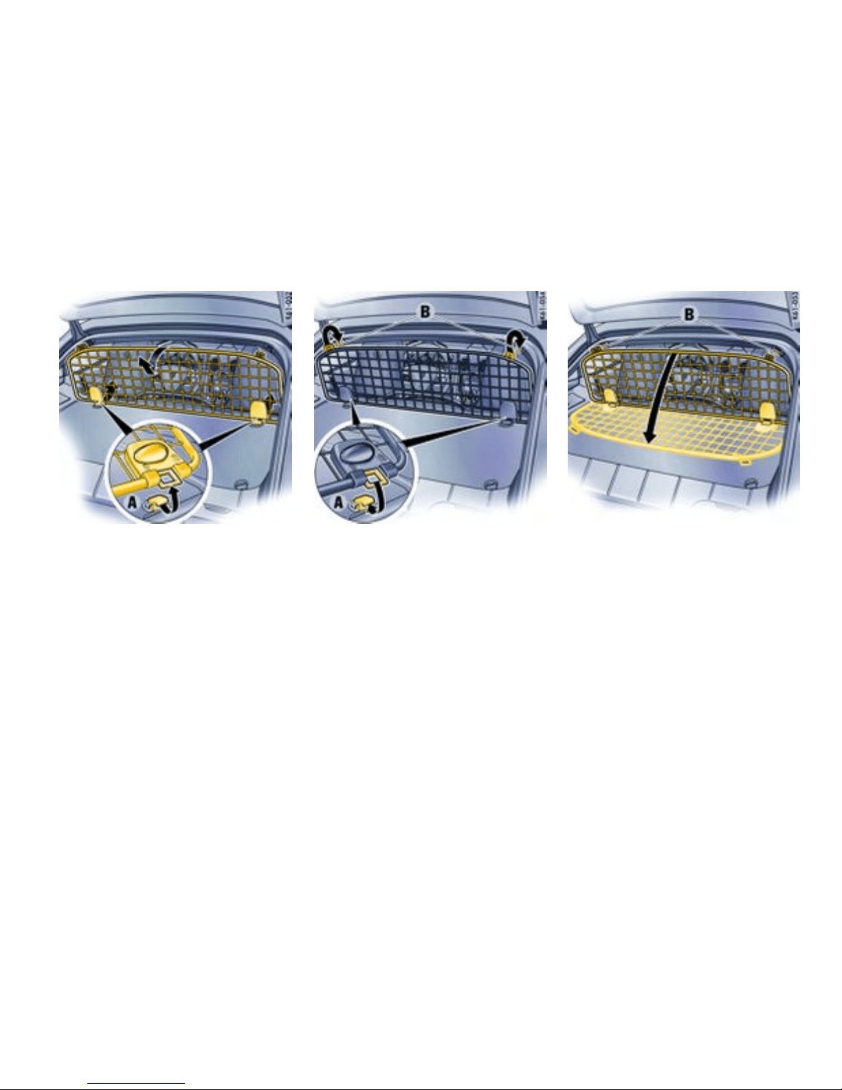
3. Put cargo partition at an angle and l ift out from
the lower mounts A.
Installing cargo parti tion
1. Turn b oth turn-locks to ”Lock open“ on the
cargo part ition.
2. Engage opened locks in the lower mounts A.
3. Lift cargo partition somewhat and engage in
the upper hooks B on both sides.
4. Turn b oth turn-locks to ”Lock closed“ on the
cargo part ition.
Folding carg o partition forward
The luggage net must be disengaged before
folding the cargo part ition forward.
1. Turn both turn-locks to ”Lock open“ on the
cargo partition.
2. Lift the cargo p artition somewhat and disen-
gage on both sides from the upper hooks B
and hold.
3. Fold the cargo partition forward carefully (do
not press down with force) and lay it on t he
carpet. Make sure that the partition does not
slip out of t he lower mounts.
Controls, Instruments
181
Downloaded from www.ManualsFile.com manuals search engine

4. Turn both turn-locks to ”Lock closed“ on the
cargo parti t i on.
Luggage cover
The luggage cover protects luggage in the rear
storage area from direct sunlight and curious eyes.
Caution!
Risk of damage to luggage cover from
sharp -edged or sliding pieces of luggage.
Always remove luggage cover when pieces of
luggag e can damage the luggage cover.
182Controls, Instruments
Downloaded from www.ManualsFile.com manuals search engine
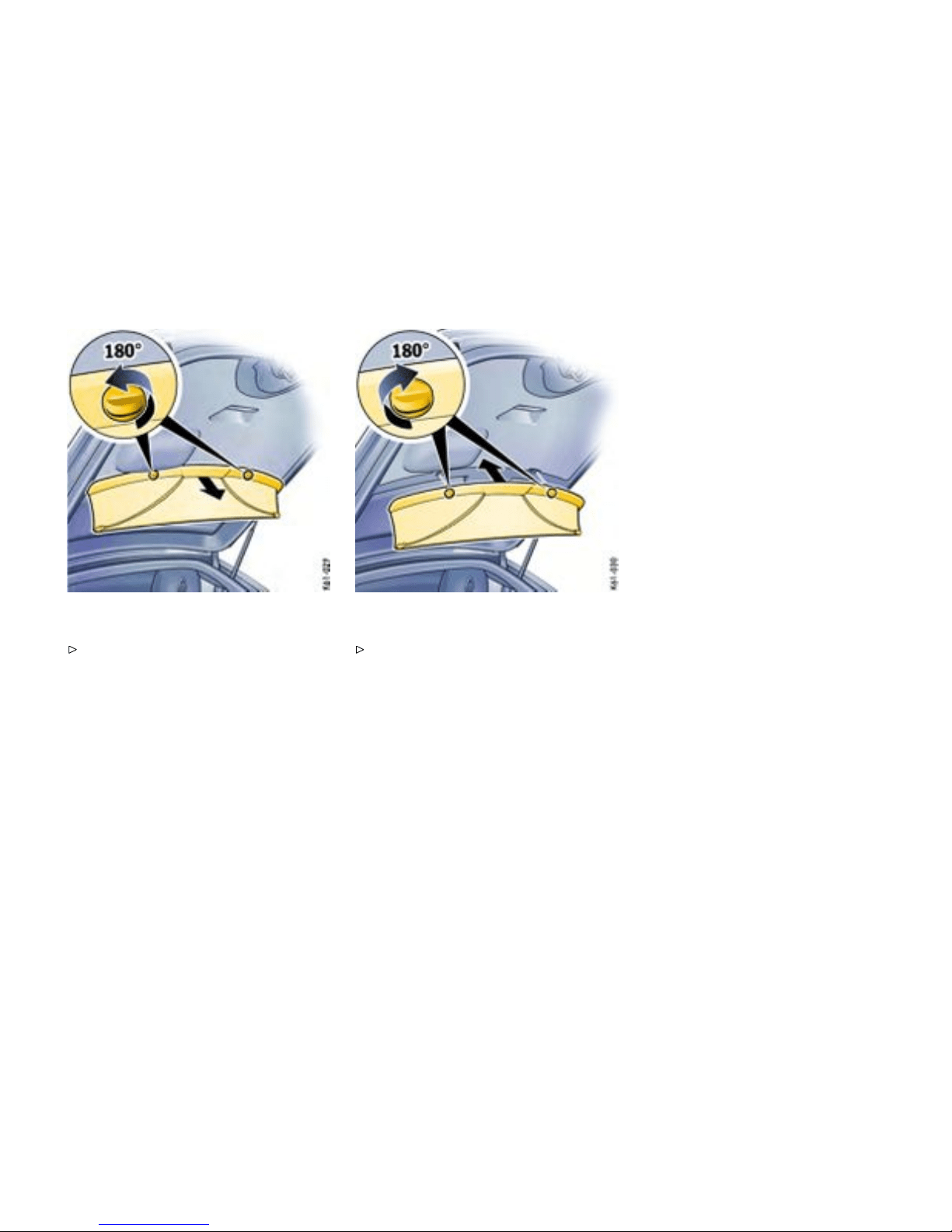
Removing the luggage cover
Hold luggage cover with one hand and loosen
both turn-locks. Remove the luggage cover
using both hands.
Installing the luggage cover
Place luggag e cove r into the mounting s with
both hands, hold it with one hand and lock both
turn-locks.
Controls, Instruments
183
Downloaded from www.ManualsFile.com manuals search engine

Porsche Communicati on
Manageme nt (PCM)
General in formation t o the Porsch e
Communication Manage ment (PCM)
Refer to the separate operating instru c tions
before putting the PCM into operation.
Please observe the chapter ”LOAD SWITCH-
OFF AFTER 2 HOURS OR 7 DAYS” on page
259.
Warning!
There is danger of accident if you set or
operate the on-board computer, radio,
navigation system, telephone or o ther
equipment when driving. This could distract
you from trafc and cause you to lose control
of the vehicle resulting in serious personal
injury or death.
Operate the components while driving only if
the traffic situation allows you to do safely.
Carry out any complicated operating or setting
procedures only with the vehicle stationary.
The recep tion conditions for the radio module
integrated in the PCM change continuously as
you drive. Interfe rence from buildings, terrain and
the weather is unavoidable. FM stereo reception
is parti cularly susceptible to varying reception
conditi ons.
Electronic accessories should only be retrofitted
by your authorized Pors che dealer.
Accessories which have not been tested and
approved by Porsche may impair radio function
and reception.
Navigation
When put into operation for the first time, a
distance of approx. 31 miles (50 km) must be
driven in order for the navigation system to
complete the proces s of fine calibration. The
same applies when the tires are changed (e.g.
summer/snow tires) or new tires fitted. Full
location accuracy is not yet achieved during the
fine-calibration process.
If the vehicle has been transported (e.g. fer ry,
car train), the system may take a fe w minutes to
determine the current location after it has been
switched on.
Serious tire slip (e.g. spinning wheels on snow)
may result in temporarily inaccurate navigation.
When the battery has been disconnec ted, it ma y
take up to 15 minutes before the navigation system
becomes operational again.
184Controls, Instruments
Downloaded from www.ManualsFile.com manuals search engine

Car Aud io Operation/Tips
Gener al information
For radio operation see your radio manual
which is included with your on-board litera-
ture.
Please observe the chapter ”LOAD SWITCH-
OFF AFTER 2 HOURS OR 7 DAYS” on page
259.
FM rece ption
A vehicle is not an ideal place to listen to a radio.
Because the vehicle mov es, reception conditions
are constantly changing. Buildings, terrain, signal
distance and noise from other vehicles are all
working again st good reception. Some cond itions
affecting FM may a ppear to be problems when they
are not.
The following characteristic s are completely
normal for a given recepti on area, and they do
not indicate any problem with the radio itself.
Note
Electronic accessories should only be installed by
your authorize d Porsc he dealer. Equipment which
has not been tested and approved by Porsche may
impair radio function and reception.
Fading a nd drifting
FM range is limited to about 25 miles (40 k m),
except for some high power stations.
If a vehicle is moving away from the desired
station’s transmitter, the signal will tend to fade
and/or drift . This condition is more prevalent
with FM than AM, and is often accompanied by
distortion. Fading and drifting can be minimized to
a certa i n degree by careful attention to fine tuning
or selection of a stronger s ignal.
Static and uttering
When the line-of-sight link between a transmitter
and vehicle is blocked by large buildings or moun-
tains, the radio sound may be accompanied with
static or fluttering because of the characteristic of
FM. In a similar effect, a fluttering noise is some-
times heard when driving along a tree-lined road.
This static and fluttering can be reduced by adjust-
ing the tone control for greater bass response until
the disturbance has passed.
Multipath
Because of the reflecting characteristics of FM,
direct and reflected sign als may reach the antenna
at the same time (multipath ) and cancel each other
out. As a veh icle moves through these electronic
dead spots, the listener may hear a momentary
flutter or loss of reception.
Station swapping
When two FM stations are close to each other, and
an electronic dead spot, such as static or multipath
area, interrupts the origina l signal , sometimes
the stronger second signal will be selected
automatically until the original one returns. This
swapping can also occur as you drive away from
the selected station and approach another s tation
of a stronger signal.
Controls, Instruments
185
Downloaded from www.ManualsFile.com manuals search engine

Compact disc player
Caution!
To avoid damage to compact disc player and
discs.
Use only compact discs labeled as shown,
having no dirt, damag e or warpag e.
Never attempt to disassemble or oil any part
of the player unit. Do not insert any object
other than a disc into the sl ot. Remember
there are no user-serviceable parts inside the
compact disc p layer.
Do not allow the disc t o sustain any finger-
prints, scrapes or stickers on the surfaces.
This may cause poor sound quality. Hold the
disc only on the edge or center hole.
When not in use, take the disc out of the
player, put the disc back into its ca se and
store it awa y from dust, heat, damp and direct
sunlight. Leaving the disc on the dashboard in
the sun can damage the disc.
If the disc gets dirty, clean the disc by wiping
the surf aces from the center to the outside
in a radial direction with a soft cloth. Do
not use a conventional record cleaner or
anti-static record preservative. Dis c cleaners
are available in audio stores.
Antenna
Always unscrew the external antenna before
using an automatic car-wash.
Car Telephone and A ftermarket Alarms
Important l egal and safety informa tion
regarding the use of cellular telephones:
Danger!
Risk of an accident . Severe personal injury or
death can result in t he event of a n accident.
Lookin g away from the road or turning your
attention away from your driving can cause an
accident and lead to serious personal injury
or death.
When using your cellular telephone, you should
always :
Give full attention to your driving - pull off the
road and park before making or answering a
call if traffic conditions so require; and
Keep both hands on the steering wheel - u se
hands-free operation (if available) - pull off
the road an d park before using a hand-held
telepho ne.
Some states may prohibit the use of cellular
telephones while driving a vehicle. Check the laws
and regulations on the use of cellular telephones in
the areas where you drive.
It is e ssential to observe the instructions of the
telephone manufacturer before putting the
telephone into operation.
186Controls, Instruments
Downloaded from www.ManualsFile.com manuals search engine
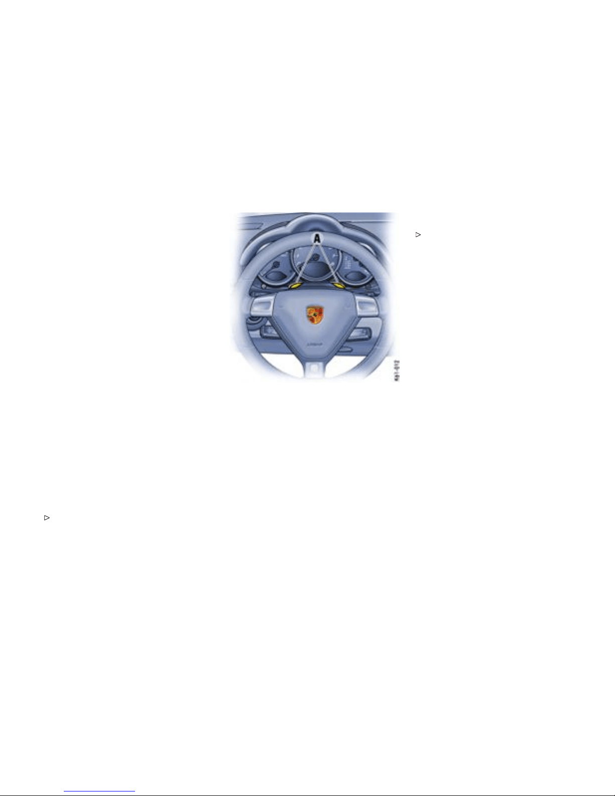
Any porta ble telephone or radio transmitter which
is used in a Porsche must be properly installed
in accordance with the technical requirements of
Porsche.
The transmission power must not exceed
10 W. The devices must possess a ty pe approval
for your vehicle and have an “e” symbol.
If you should require equipment with transmission
power values greater than 10 W, please consult
your authorized Pors che dealer for this purpose.
He is familiar with the technical requirements for
installing d evices of this kind.
The antennas for all radios and telephones with a
transmitting antenna must be externally mounted.
The improper installation of radios or telephones
or use of a radio or telephone with a transmitting
antenna inside the car may cause the warning
lights to come on.
Improper installation of such equipment can create
a discharged battery or excessi v e current draw
from added equipment.
If aftermarket systems are installed by non-deal-
ership technicians or outside the selling dealer,
problems may result. Installation of aftermarket
equipment is not covered under the New Car War-
ranty.
Consult your authorized Porsche dealer about
the installation of non Porsche approved
equipment.
Hands-fr ee microphone
Hands-free microphones A installed at t he factory
must be adapted to the type of telephone in use.
Your a uthorized Porsche dealer will be pleased to
advise you.
Reception quality
The reception quality of your car telephone
will change constantly when you are driving.
Interference caused by buildings, landscape and
weather i s unavoidable. It may become particularly
difficult to hear when using the hands-free function
due to external noise such as engine and wind
noise.
Automatic car-wash
Unscrew external antennas before usi ng an
autom atic car-wash.
Controls, Instruments
187
Downloaded from www.ManualsFile.com manuals search engine
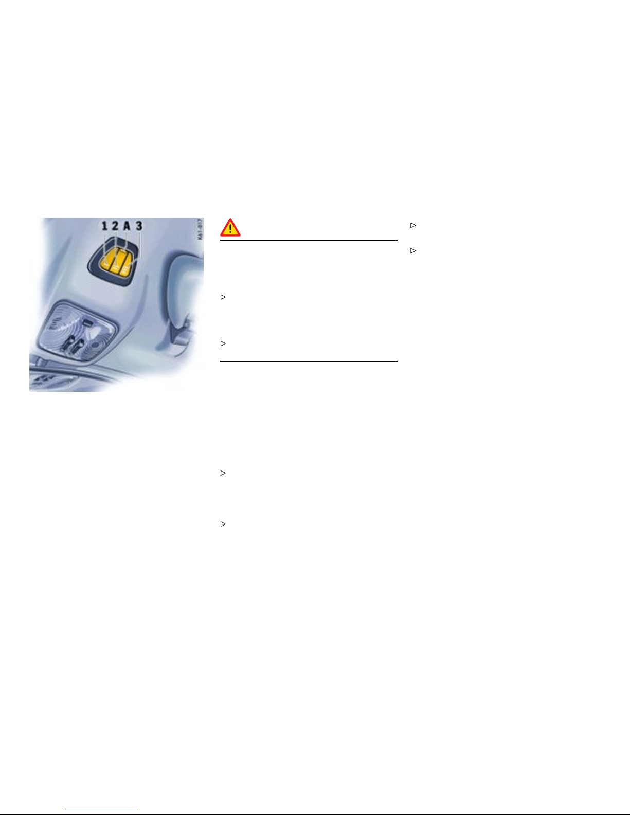
1-3 - Programmable buttons
A - Light-emitting diode for status identication
HomeLink
Functi on of the Home L ink
The programmable Home Link replaces up to three
original hand-held transmitters used to operate
various device s (e.g. garage door, gate to the
property, alarm system).
You can program buttons 1 to 3 with a frequency
of an original handheld tran s mitter.
Warning!
Risk of acciden t when using the HomeLink
if persons, animals or objects are within the
range of movement of the eq uipment that is
being operated.
When using the HomeLink, ensure tha t no
persons, animals or o bjects are within the
range of movement of the equipment that is
being operated.
Observe the safety notes for the original
hand-held transmitter.
Preconditions for operati ng and
programming the HomeLink:
– Ignitio n is switched on.
– Fog lights are switched off.
To opera te the respe ctive device:
Press the appropriate button (1, 2 or 3).
Light-emitting diode A lights up during signal
transfer.
Note on operation
Always use the HomeLink opener in th e direc-
tion of travel. Otherwise, range restrictions
cannot be ruled out.
Before selling the vehicle, delete the pro-
grammed signals of the HomeLink.
Please read the instructions for the original
hand-held transmitter to find out whether the
original transmitter is equipped with fixed or
changeable code.
188Controls, Instruments
Downloaded from www.ManualsFile.com manuals search engine
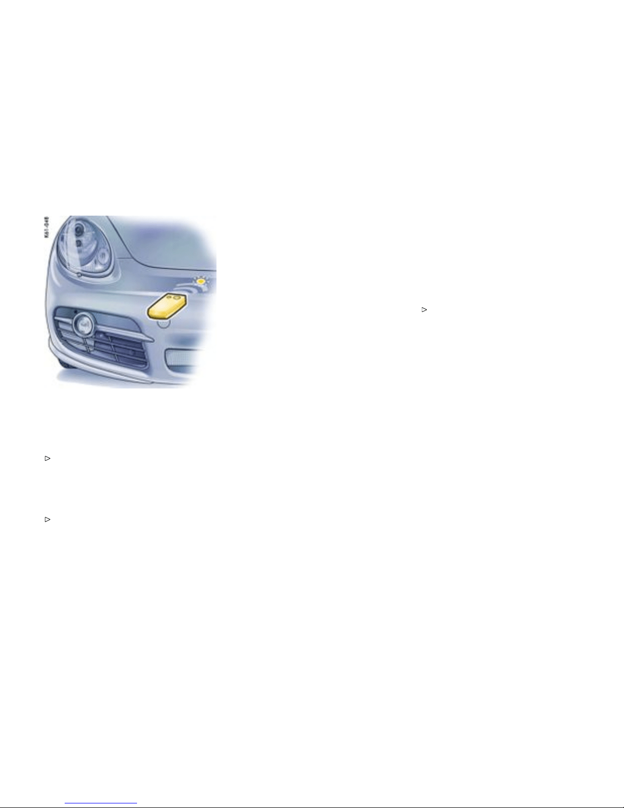
Allocating signals to the buttons
Prior to programming th e HomeLin k for the
rst time
Please follow the operatin g instructions for the
original hand-held transmitter.
The following process deletes the standard codes
set at the factory. Do not repeat the process if you
program further b uttons.
Keep the two outer buttons 1 and 3
depressed for approx. 20 seconds until
light-emitting diode A begins to flash quick-
ly. All programmed signals of buttons 1 to 3
are deleted.
HomeLink with xed code system
1. Press the desired button until the light-emitting
diode begins to flash slowly. You then have
approx. 5 minutes to perf orm steps 2 and 3.
2. Hold the original hand-held transmitter approx.
0 to 12 in. (0 to 30 cm) in front of the marked
position (figure) on the vehicle.
3. Press the transmit button on the original
hand-he ld transmitter until the fog lights flash
three times (up to a p prox. 45 seconds).
4. Repeat steps 1 to 3 to allocate other buttons.
Note
Several attempts with different distances between
the vehicle and the original hand-held transmitter
might be necessa ry.
The fog lights will flash once the 5 minutes have
been exceeded. Programming must be repeated
from the beginning in this case.
HomeLin k with changeable code s ystem
1. Allocate the required keys as f or t he systems
with fixed code (steps 1 to 3).
2. To synchronise the system: Press th e pro-
gramming button on the receiver for the
garage door actua tor. Afterwards, you usu-
ally have approx. 30 seconds to initiate step 3.
3. Press the allocated HomeLink button twice .
(With some devices, the button to be allocated
must be pressed a third time in order to
complete the setting process.)
4. Repeat the programming steps to allocate
other buttons.
Note
Please consu lt an authorized Porsche dealer
if you have not been able to successfully
allocate signals for the garage door opener
to the buttons even though you have carefully
followed the instructions in this chapter and
the operating instructions for the original
hand-held transmitter.
To reprogram a single button:
1. Press the desired button until the light-
emitting diode begins to flash slowly (approx.
20 seconds). You then have approx. 5 minutes
to perform steps 2 a nd 3.
2. Hold the original hand-held transmitter approx.
0 to 30 cm in f ront of the marked position
(figure) on the vehicle.
3. Press the transmit button on the original
hand-held transmitter until the fog lights flash
three times (up to approx. 45 seconds).
4. Repeat steps 1 to 3 to allocate othe r buttons.
Controls, Instruments
189
Downloaded from www.ManualsFile.com manuals search engine

Note
Several attempt s with different distances between
the vehicle and the hand-held transmitter might be
necessary.
The fog lights will flash once the 5 minu tes have
been exceeded. Programmi ng must be repeated
from the beginning in this case.
Deleting programmed signals of the HomeLink
(e.g., when selling the vehicle)
Keep the two outer buttons 1 a nd 3 depressed
for approx. 20 seconds until light-em itting diode A
begins to flash quickly. All programmed signals of
buttons 1 to 3 are deleted.
190Controls, Instruments
Downloaded from www.ManualsFile.com manuals search engine
Roof Transport System
Please follow the separate instructions for
fitting the Roof Tra nsport System.
Only use Roof Transport Systems from the
Porsche Tequipment product range or Roof
Transport Systems which have been tested
and approved for your car by Porsche. Fitting
normal commercially available luggage racks
is not possible.
The Porsche Roof Transport System allows you
to carry various sports and hobby equipment. Your
Porsche partner will be pleased to tell you about
the various different uses of the Roof Transport
System .
Caution!
Risk of damage to the paint on the rear lid.
Only open the rear lid if this cannot touch the
load.
Completely remove the Roof Transport
System before using an automatic car wash -
risk of damage to the vehicle!
Do not exceed the maximum permitted
payload of 132 lbs. (60 kg), the maximum
permitted gross weight and the maximum
permitted axle loads.
Please observe the chapter ”WEIGHTS” on
page 302.
Distribute load evenly, storing heavy items as
low as possible. Items of luggage must not
project beyond the side of the load area.
Fix and secure every item to the basic carrier
with a rope or lashing strap (do not use elastic
rubber tension ers).
Before every trip, and at regular intervals
during long trips, check that Roof Transport
System and load are secure. Re-tighten if
necessary and secure a dditional ly by locking.
When the Roof Transport System is lo aded, the
maximum speed depends on the nature, size
and weight of the load being carried. But never
drive faster than 90 mph (140 km/h).
With the basic carrier fitted and no load, do
not exceed a maximum speed of 110 mph
(180 km/h).
Driving, braking and steering behavior change
due to the higher center of gravity and the
greater wind-resistant area. You should adapt
your driving style appropriately.
Since fuel consumpti on and noise are
increased with the Roof Transport System
fitted, it should not remain on the vehicle if not
in use.
Controls, Instruments 191
Downloaded from www.ManualsFile.com manuals search engine


Manual T ransmission, Clutch
Gener al information
The positions of the gears are shown on the shift
diagram on the gearshift lever.
Warning!
Risk of accident, resulting in serious personal
injury or death.
Do not obstruct the pedal travel with floor mats
or other objects. Nonskid floor mats of the
correct size are available at your authorized
Porsche dealer.
Warning!
To avoid damage to the clutch and transmis-
sion:
Always depress the clutch pedal fully when
changing gears. Make sure that the gearshift
lever is completely engag ed.
Only shift into reverse when the car has come
to a c omplete stop.
When shifting gears , always ensure that the
clutch pedal is fully depressed and the gear
has fully engaged.
Select reverse only when vehicle is stationary.
Select an appropriately low gear on upward
and downwa rd slopes. T his will ensure
optimu m use of engine power and engine
braking.
When reverse gear is se lected and the ignition is
on, the backup lights are illuminated.
Permitted engine s peed
You should change into a higher gear before
the needle reaches the red mark on the
tachometer, or ease off the accelerator.
If the red zone is reached during acceleration, fuel
feed is interrupted.
Caution!
Risk of engine damage (overrevving) when
shiftin g down to a lower gear.
Take care not to exceed the m aximum
permitted engine speed when shifting down.
194Shifting Gear
Downloaded from www.ManualsFile.com manuals search engine

Tiptronic S
Function of Tiptronic S
The Porsche Tiptronic is a five-speed transm ission
with an “automatic” and a “manual” selection
mode.
In automatic selection mode (selector lever
position D), gear changing i s automatic. You can
change temporarily from automati c to manual
mode using the rocker switches on the steering
wheel.
In manual selection mode (selector lever
position M), you change gear using the rocker
switches on the steering wheel .
You can change between selector lever position D
and M as you wish while driving.
Note
Take care not to operate the rocker switches
on the steering wheel inadvertently in either
auto matic or manual mode, thereby triggering
undesired gear changes.
Keylock position
The ignition key can be withdrawn only in selector
lever position P.
Transmission selecto r l ever
Changing the selecto r lever position
The selector lever is locked with the ignition key
withdrawn.
The selector lever can be moved from position P or
N only with:
– the ignition switched on,
– the brake pedal pressed and
– the release button pressed.
Release b utton
The release button (arrow) in the selector lever
prevents unintent ional gear changes.
The release button must be pressed when shifting
to position R or P.
Starti ng
The engine can be started only if the brake pedal is
depressed and the selector lever is in position P or
N.
Moving off
Only select the desired position for moving off
(D, M or R) when the engine is idling and the
brake pedal is depressed.
Since the vehicle creeps when in g ear, do not
release the brake until you want to move off.
After selecting a gea r, do not accelerate until
you can feel that the gear is engaged.
Shifting Gear
195
Downloaded from www.ManualsFile.com manuals search engine
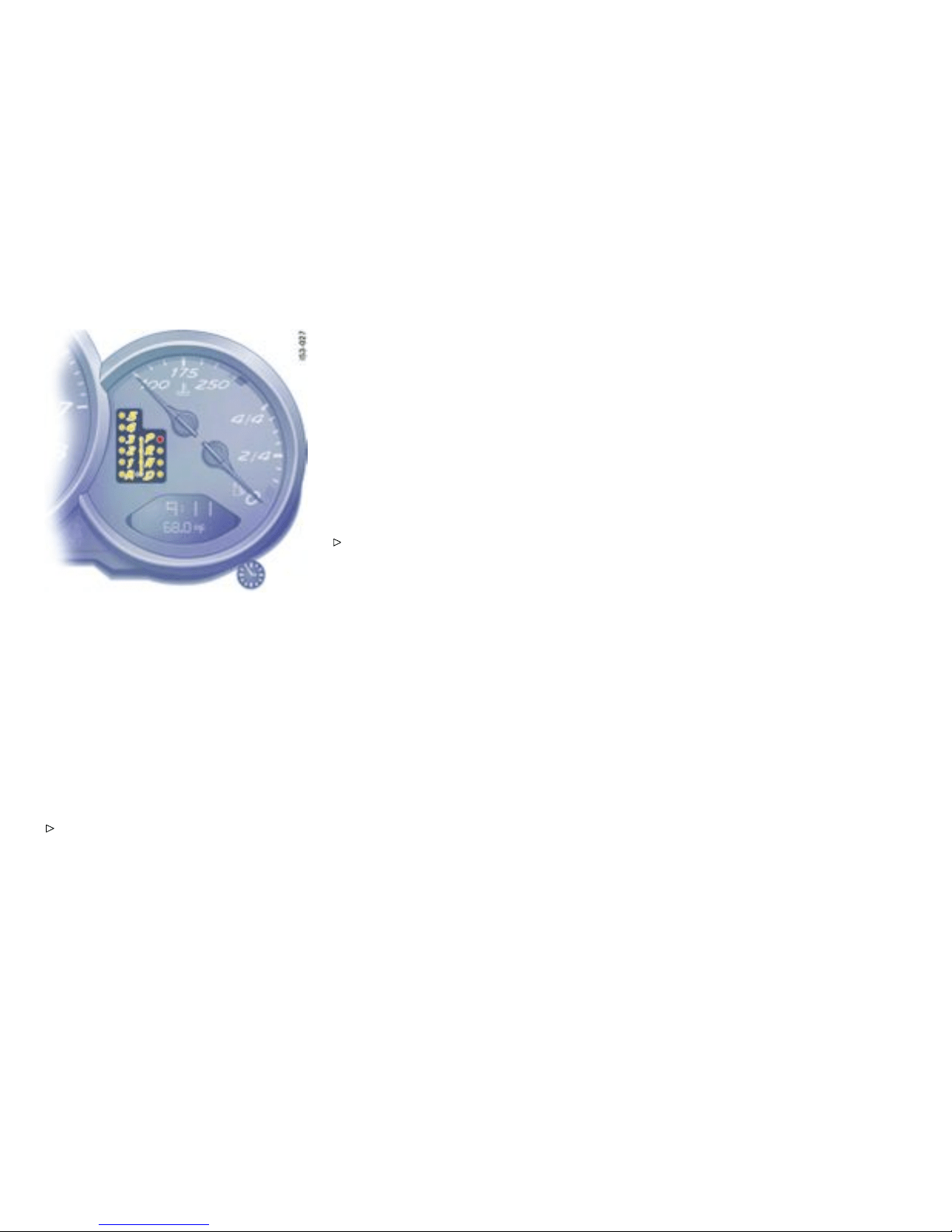
Selector lever position and engaged gear
Indicator
When the engine is running, the selector lever
position and engaged gear are indicated.
If the selector lever i s between tw o positions:
– The corresponding selector lever position in
the instrume n t cluster flashes and
– the warning “Selector lever not engaged”
appears in the on-board computer.
Engage the selector lever correctly.
– The selector lever position is displayed
immediately after the correct position has
been detected.
– The current gear is shown after a brief
detection period.
If there is a fault in the transmission:
– The 4th-gear and the selector lever position
select ed displays flash in alternation.
– The warning “Tiptronic emergency run”
appears on the on-board computer.
Please observ e the chapt er ”EMERGENCY
PROGRAM” on page 199.
– Have the fault remedied at an authorized
Porsche dealer.
196Shifting Gear
Downloaded from www.ManualsFile.com manuals search engine

Selector Lever P ositions
P - Parking lock
Engage parking lock only when vehicle is
station ary.
Engage parking lock after applying the
handbrake and release it before releasing
the handbrake.
The ignition key can be withdrawn only in selector
lever position P.
R - Reverse
Select only if car is stat ionary and the brake is
applied.
N - Neutral
Selector lever position N must be selected for
towing or in car washes, for example.
Select the desired position for moving off (D,
M or R) only when the engine is idl ing and while
depressing the brake pedal.
D - Autom atic selection mode
Mode of operation
Select position D for “normal” driving. The
gears are shi fted automatically according to
the accelerator position and speed.
Depending on the way the vehicle is driven and
on the resistance (e.g. uphill), the gear-changing
points are shifted towards hi gher or lower engine-
speed ranges. The accelerator position, driving
speed, engine speed, l ongitudinal and lateral
accele ration and the road profile all have an
influence on the gear-changing characteristic.
Unwanted upward shifts, e.g. before bends, are
prevented by swiftly releasing the accelerat o r
pedal.
Depending on lateral acceleration, upward shifts
on bends are not made until the engine-speed limit
is reached.
Under brakin g, and depending on the amount of
decele ration, the Tiptronic shifts down earlier. For
subsequent cornering, the right gear is engaged
when pressure is applied to the brakes befo re the
bend. The bend is taken in the right gear, and when
you accelerate out o f the bend you do not have to
shift down.
Sport mo de switche d on
Please observe the chapter ”SPORT MODE” on
page 72.
If the Sport mode programme is switched on,
Tiptronic switches to a sporty gear-changing map
and shortens the shifting periods.
Initial Drive-off
In 2nd gear, the vehicle drives off with the throttle
only slightly open. Drive off in 1st gear with the
throttle open wider or when the engine is c old.
Shifting ge ar on the st eering wheel
With the toggle switches on the steering wheel, you
can change temporarily from aut omatic selection
mode D to manual mode M.
Advanta ges:
– Shifting down before ben ds and on entering
built-up areas.
– Shiftin g down on downward slopes (engine
braking).
– Shifting down for brief spurts of acceleration.
– Selecting 1st gear for moving off.
The manua l selection mode remains engaged:
– for cornering (depending on the lateral
acceleration) and overrunning,
– when the vehicle is stationary (e.g. at a
junction).
The system leaves manu al selection mod e:
– autom atically after approx. 8 seconds (unless
cornering or overrunnin g),
Shifting Gear
197
Downloaded from www.ManualsFile.com manuals search engine
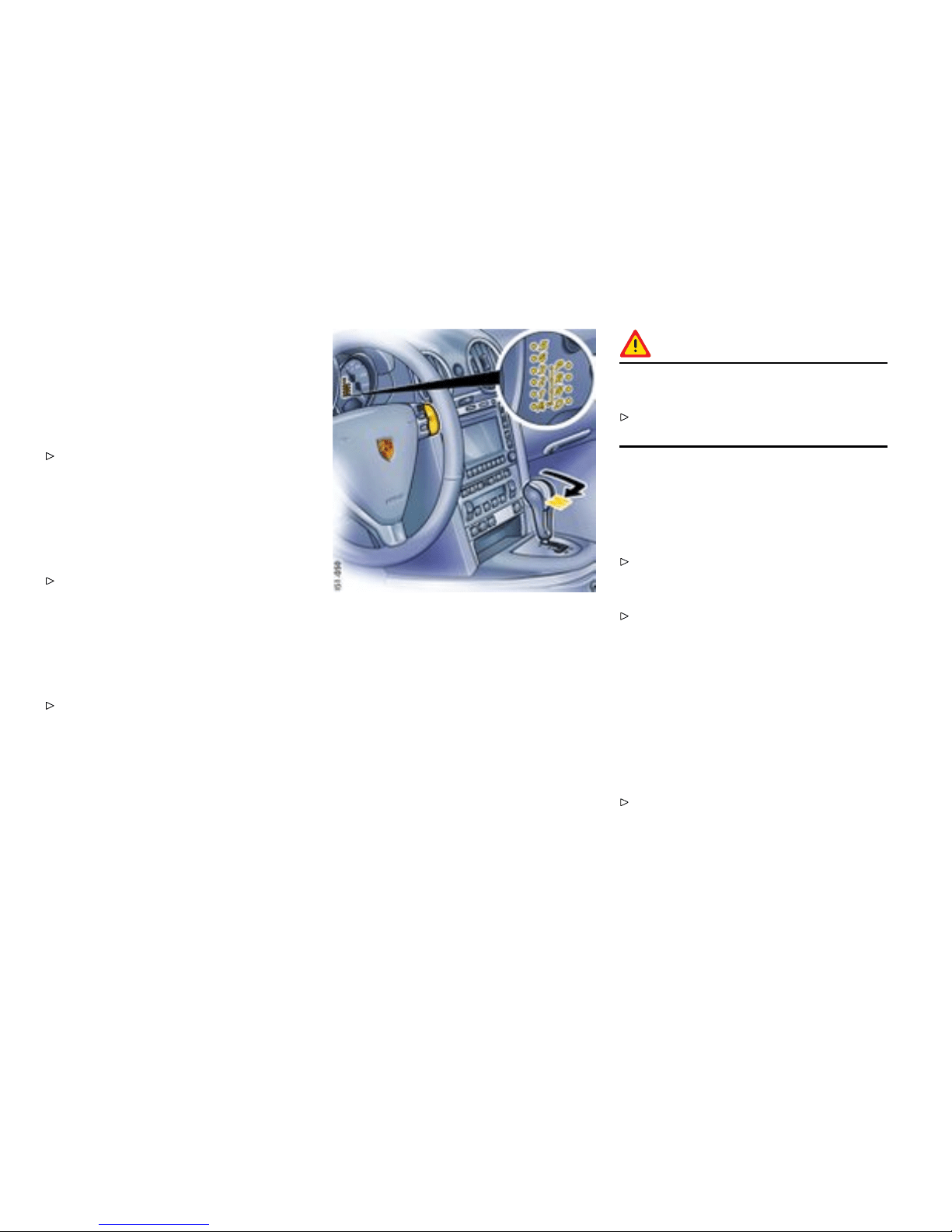
– if you depress the accelerator to kickdow n,
– after moving off.
Temporary change-down
Conditions: Speed is higher than approx.33 mph
(54 km/h).
Depress accelerator quickly. The Tiptronic
changes temporar i ly to th e spo rtiest gear-
changing map, i.e. to the highest possible
gear-c hanging points. Correspondingly, the
transmission shifts down immediate ly by one
or two gears.
Ending the function:
Release the accelerator markedly.
Kickdown
The kickdown function is active in se lector lever
position D, even if you temporarily change to
manual mode M using the toggle switches on the
steering wheel.
For optimum acceleration, e.g. when overtak-
ing, depress the accelerator pedal beyon d the
full-throttle point (kickdown).
The transmission shifts down depending on the
speed of travel and engine speed. Upward shifts
occur at the highest possible engine speeds.
These gear-cha nging speeds remain active until
the accelerato r is released to approx. 80% of the
wide open throttle position.
M - Manual S election Mode
Mode of operation
The currently selected gear is retained if you
change from D to M.
If you shift from M to D, the gear-changing map
suitable for your current driving style is selected
and the appropriate gear is selected.
Warning!
The kickdown function is not active in manual
selection mode “M”.
Therefore s hift down manually when accelerat-
ing (e.g. to overtake).
Two toggle switches in the upper steering-wh e el
spokes let you comfortably and reliably select the
five forward gears.
Shifting up
Press upper part (+) of a toggle switch.
Shifting down
Press lower part (-) of a toggle switch.
Depending on driving speed and engine speed,
you can shift up or down at an y tim e. Gear changes
which would exceed the upper or lower engine-
speed limit are not executed by the controller.
You can shift down two gears at once by quickly
pressing the toggle switches twice.
If the engine-sp eed limit is reached, an auto matic
upward shift is performed or, just before idling
speed is reached, a downward shift i s performed.
Select an appropriately low gear on upward
and downward slope s. This will ensure
optimu m use of engine power and engine
braking.
198Shifting Gear
Downloaded from www.ManualsFile.com manuals search engine
If manual mode fails, the control electronics switch
to automatic mode. In this event, the instrument
cluster will display selector lever position D.
To remedy the fault, please consult an author-
ized Porsche dealer.
PSM switched off and/or Sport mode switched
on
Please observe the chapter ”SWITCHING OFF
PSM” on page 74.
Please observe the chapter ”SPORT MODE” on
page 72.
If the PSM is switched off and/or Sport mode is
switched on, an automatic upshift does not occur
when the engine speed limit is reached.
Cancelling upshift suppression
The restriction can be cancelled for one gear
change by depressing the accelerator to kickdown.
If, for example, the engine speed limit is reached
during overtaking and the automatic upshift does
not occur, the transmission in this case shifts up by
accelerating to kickdown.
Depress the accelerator pedal beyon d the
full-throttle point (kickdown).
Manual mo de failure
If manual mode fails, the control electronics switch
to automatic mode. In this event, the instrument
cluster will display selector lever position D.
Have the fault remedied. Consult an author-
ized Porsche dealer.
Stopping
For a brief stop, e.g. at a traffic light, leave the
selector lever in drive position and hold the
vehicle with the brake pedal.
For a lo nger stop with the e ngine running,
select position N (neutral).
Do not hold the car on a slope using the
accelerator. Use the brake pedal or the
handbrake instead.
Before leaving the vehicle, always apply the
handbrake and move the selector lever to
position P.
Parking
Go easy on the accelerator.
When parking or maneuver ing in a small
space, control the speed by careful use of
the footbrake.
Driving in winter
In wintery road conditions it is a dvisable to take
steep inclines in manual mode. This prevents the
occurrence of gear changes that could cause
wheels pin.
Tow-starting, towing
Please observe the chapter ”TOWING” on page
287.
Emergency prog ram
Warning!
Reverse gear lock monitoring is disabled in
the emergency running program. Damage
to the vehicle may result as well as loss of
control, if the vehicle is moving forward fast
enoug h to cause rear wheel lockup.
Do not shift i nto R w hile the vehicle is moving
forwa rd.
A transmission fault is indicated by the following
symptoms:
– The 4th-gear display flashes.
– The warning “Tiptronic emergency run”
appears in the on-bo ard computer.
– The transmission no longer shifts. Regardless
of selector lever position, 4th is th e only
forward gear still available.
Adapt your driving style to the changed
handling.
To remed y the fault, please consult an author-
ized Porsche dealer.
Shifting Gear
199
Downloaded from www.ManualsFile.com manuals search engine


Mainten ance, Car Care
Exercise Extreme Caution when Working on your
Vehicle ......................................... .............. 202
Wiper Blades .............................................. 203
Coolant Level .............................................. 205
Engine Oil ....... ............................................ 207
Engine Oil Level ........................................... 208
Engine Oil Recommendation ......................... 210
Brake Fluid Level ......................................... 212
Fuel Economy ............................................. 214
Operating your Porsche in other Countries ..... 215
Fuel ........................................................... 216
Portable fuel containers ............................... 218
Fuel Recommendations ................................ 219
Emission Control System ............................. 220
How Emission Control Works ........................ 221
Fuel Evaporation Control .............................. 222
Washer Fluid ......................................... ...... 223
Power Steering ........................................... 224
Filter .......................................................... 225
Automatic Transmission Fluid ........................ 226
Manual Transmission Oil .................. . ............ 227
Car Care In structions ................................... 228
Maintenance, Car Care
201
Downloaded from www.ManualsFile.com manuals search engine

Exercise Extreme Ca u t ion when
Working on your Vehicle
Danger!
Ignoring the fo llowing instructions may cause
serious personal injury or death.
The engine compartment of any motor vehicle
is a potentially hazardous area. If you are not
fully familiar with proper repair procedures, do
not attempt the adjustments described on the
following pages. This caution applies to the
entire vehicle.
Only work on your vehicle outdoors or in a well
ventilated area.
Ensure that there are no open flames in
the area of your vehicle at any time when
fuel fumes might be present. Be especially
cautious of such devices such as hot water
heaters which ignite a flame intermittently.
Before working on any part in the engine com-
par tment, turn the engine off and let it cool
down sufficiently. Hot engine compartment
components can burn skin on contact.
Be alert and cautious around engine at all
times while the engine is running. If work has
to be performed with the engine running,
always set the parking brake, and make sure
the shift lever is i n neutr al or the selector lever
is in position P or N.
In particular, be very careful to ensure that
items of clothing (ties, shirt, sleeves etc.),
jewelry, long hair, hand or f ingers cannot get
caught in the engine-compartment blower, fan,
belts or other moving parts. The radiator and
radiator fans are in the front of t he car. The
fans can start or continue running as a functi on
of temperature, eve n with the engine switched
off. Carry out work in these areas only with the
engine off and exercise extreme caution.
Your Por sche is equipped with an electronic
ignition system. When the ignition is on,
high voltage is present in all wires connected
with the ignition syste m ; therefore, exercise
extreme caution when working on any part of
the engine while the ignition is on or the engine
is running.
Always place the vehicle on stable supports if
work has to be ca rried out under the vehicle.
Jacks are not suitable for this kind of work.
When workin g under t he car without safety
stands but with the wheels on the ground,
make sure the car is on level ground, the
wheels are blocked, and that the engine
cannot b e started. Remove the ignition key.
Do not smoke or allow an ope n flam e around
the battery or fuel. Keep a fire ext inguisher
close at hand.
Incomp lete or improper servicing may cause
problems in the operation of the car. If in
doubt about any servicing, have it done by
your authorized Porsche dealer. Improper
maintenance during the warranty period may
affect your Porsche war ranty coverage .
Supplies of fluids, e.g. engine oil, brake fluid
or coolant, are hazardous to your healt h . Keep
these fluids out of children’s reach and dispose
of them in accordance with the appropriate
regulations.
Some countries require additional tools and
special spare parts to be carried in your
vehicle . Please make enquiries before driving
abroad.
Power m easurements
Power meas urements on dynamometers are not
approved by Porsche.
Worki ng in the engine compar tment
Have the necessary work in the engine compart-
ment done by a q ualified special ist workshop. We
recommend that you use your authorized Porsche
dealer for carrying out this work.
202Maintenance, Car Care
Downloaded from www.ManualsFile.com manuals search engine
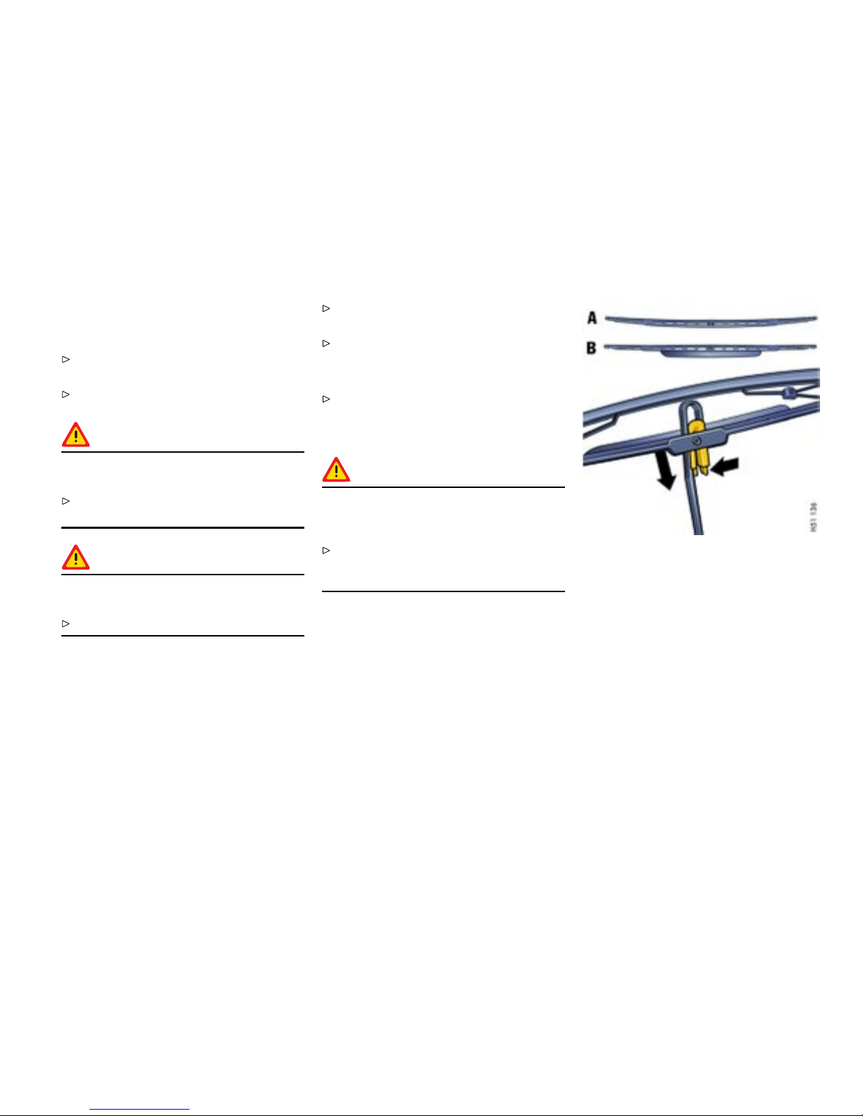
Wiper Blades
General information to the wipe r blades
When wiper performance deteriorates,
replace the wipers.
Please observe the chapter ”CAR CARE
INSTR UCTIONS ” on page 228.
Caution!
Risk of damage if the wiper arm accidentally
falls back on to t he window.
Always hold the wiper arm securely when
replacing the wiper blade.
Caution!
Risk of damage if wiper blades that are frozen
in place are loo sened improperly.
Thaw the wiper blades before loosening them.
Maintenance note
If the wiper blades rub or squeak, this can be as a
result of the follow ing:
If the vehicle is washed in an automatic car wash,
wax residues may adhere to the winds hield. These
wax residues can be removed by using window
cleaner concentrate.
Please obse rve the chapter ”WASHER FLUID”
on page 223.
Please contact your authorized Porsche deale r
for further information.
The wiper blades may be damaged.
Replace damaged wiper blades as soon as
possible.
Changing windshield wiper blades
Caution!
Risk of damage. If a wiper blade is not
changed properly, it can come loose when
the car is moving.
Check whethe r the wiper blade is seated
securely. The wiper blade must engage the
wiper arm properly.
1. Apply the handbrake.
2. Switch the wipers off (position 0) and remove
the ignition key.
3. Fold windshie ld wiper arm a way from the
windshi eld.
A - Passeng er’s side, curved wiper blade
B - Driver’s side, wiper blade with spoiler
4. Press together the plastic spring of the wiper
blade (right arrow). Pull wiper blade out of
wiper arm.
5. Insert new wiper blade until you feel it engage.
Ensure that the new wiper blade is inserted
into the wiper arm in the same position:
– direction of the spoiler on the driver side,
– curvat ure on the passenger side.
6. Carefully fold wiper arm back onto the wind-
shield.
Maintenance, Car Care
203
Downloaded from www.ManualsFile.com manuals search engine
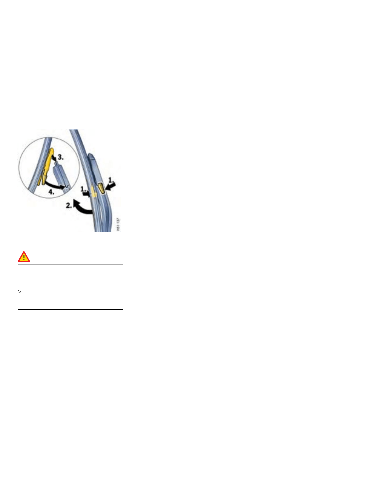
Changing rear window wiper bla de
Caution!
Risk of damage. If a wiper blade is not
chang ed properly, it can come loose when
the car is moving.
Check whether the wiper blade is seated
securely. The wiper blade must engage the
wiper arm properly.
1. Apply the handbrake.
2. Switch the rear window wiper off (position 0)
and remove the ignition key.
3. Fold wiper arm away from the rear w indow.
4. Press together the plastic spring of the wiper
blade.
5. Pull wiper blade upwards out of wiper arm.
6. Insert new wiper blade into the wiper arm from
above .
7. Press together the plastic spring of the wiper
blade and engage it in the wiper arm until it
snaps into place.
8. Carefully fold wiper arm back on the rear
window.
204Maintenance, Car Care
Downloaded from www.ManualsFile.com manuals search engine
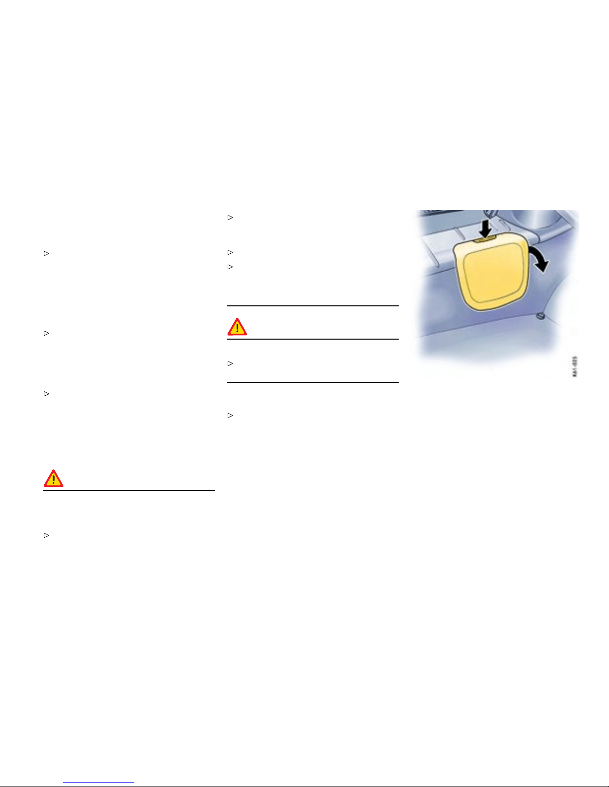
Coolant Level
General information to the coolant
Please observe the chapter ”EXERCISE
EXTREME CAUTION WHEN WORKING ON
YOUR VEHICLE” on page 202.
The cooling system is filled at the factory with
a permanent coolant. It provides year-round
protection from corrosion and freezing down to
-31°F /-35°C .
Only use antifreeze authorized by Porsche.
Checki ng coolant level
The expansio n tank for the coolant is located in the
rear luggage compartment under the service flap.
Check the coolant level regularly at the
transparent window of the ex pansion tank.
When the engine is cold and the car is level the
fluid level must lie between the “Min.” and “Max.”
markings.
Topping off coolant
Warning!
Danger of serious personal injury or death
from scalding. Coolant is hazardous to your
health, and may be fatal if swallowed.
Do not open the cap of the expansion tank
while the engine is hot.
Allow the engine to cool down before opening
the cap and protect your hands, arms and face
from any possible escape of hot coolant.
Keep coolant out of children’s reach.
Also, keep coolant away from your p ets. They
can be attracte d to it should there be a spill,
or to used coolant left in an open container.
Coolan t can be deadly to pets i f cons umed.
Warning!
Risk of damage from overowing coolan t.
Take care while topping off coolant not to soil
the luggage compartmen t or items of luggage.
1. Switch engine off and let i t cool .
Please observe the chapter ”COOLING
SYSTE M” on page 97.
2. Press catch button on the service flap and
open flap.
Maintenance, Car Care
205
Downloaded from www.ManualsFile.com manuals search engine
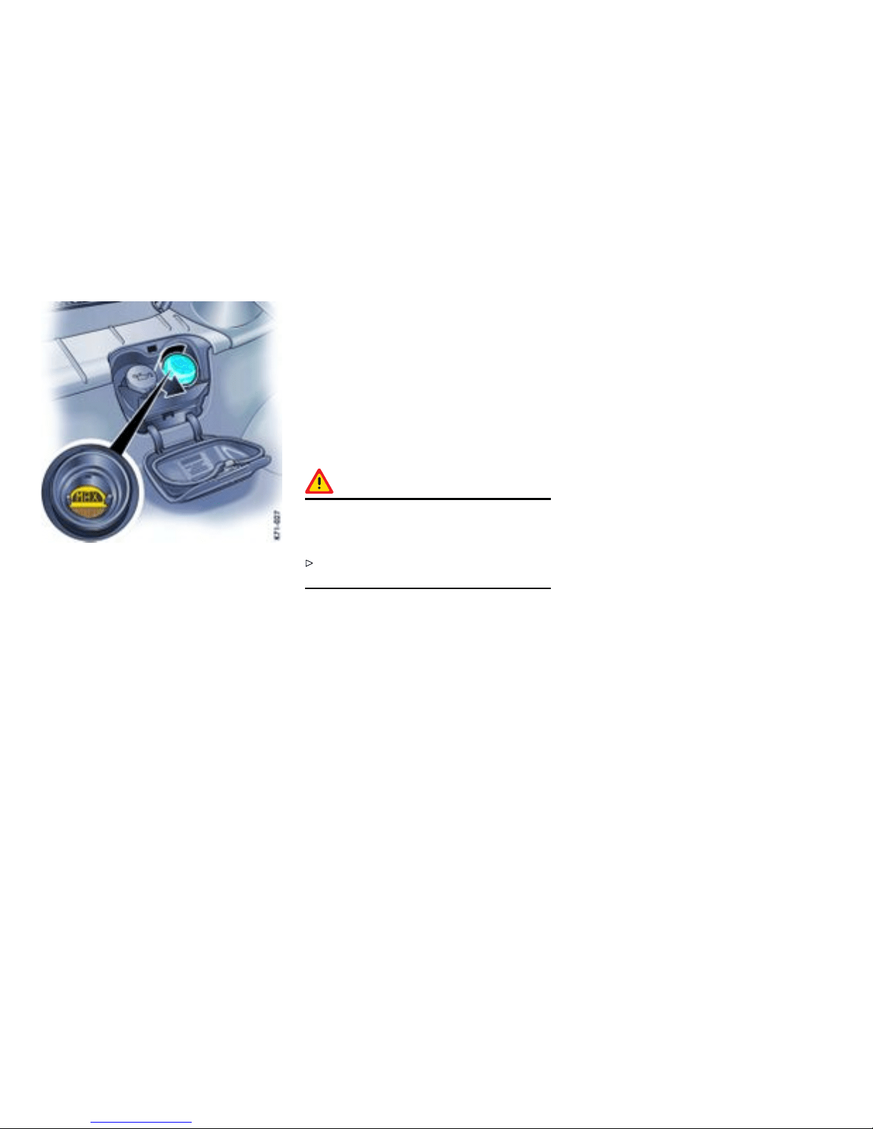
3. Cover the expansion tank cap with a thick
rag. Open cap slowly and carefully and allow
overpressure to escape. Then unscrew cap
completely.
4. If necessary, add a mixture of equal parts
antifreeze and water. Do not fill over the “max.”
marking.
Antifreeze in coolant:
50% gives protection down to - 31°F /-35°C
60% gives protection down to - 58°F /-50°C
5. Screw cap firmly on.
6. Close service flap.
If in an emergency pure water has been added,
the mix ratio must be corrected at an authorized
Porsche dealer.
Marked loss of coolant indicates leakage in the
cooling system. The cause should imm ediately be
remedied at an authorized Porsche dealer.
Radiator fans
The radiator and radiator fans are in the front of the
vehicle .
Warning!
Risk of injury. The fans can start running as a
function of temperature, even with the engine
switc hed off.
Exercise extreme caution when working in the
area of the r adiator fans.
206Maintenance, Car Care
Downloaded from www.ManualsFile.com manuals search engine

Engine Oil
Engine o il consump tion
It is normal for your engine to consume oil. The
rate of oil consumption depends on the quality
and viscosity of oil, the speed at which the engine
is operated, the climate, road conditions as well
as the amount of dilution and oxidation of the
lubrican t .
If the v ehicle is used for repeated short trips, and
consumes a no rmal amount of oil, the engine oil
measurement may not show any drop in the oil
level at all, even after 600 miles (1000 km) or
more. This is because the oil is gradually becoming
diluted with fuel or moisture, making it appear
that the oil level has not changed. The diluting
ingredients evapor ate out when the vehicle is
driven at high speeds, as on an expressway,
making it then appear that oil is exce ssively
consumed after driving at high speeds.
If the conditions you drive your vehicle in are dusty,
humid, or hot, the frequency of the oil ch ange
interva ls shoul d be greater.
If the v ehicle is driven at a high rate of speed,
climatic conditions are warm, and t he load is
high, the oil should be checked more frequently,
as driving conditions will determine the rate of oil
consumption.
– The engine in your vehicle depends on oil
to lubricate and cool all of its moving parts.
Therefore, the engine oil should be checked
regularly and kept at the required level.
– Make it a h abit to have the engine oil level
checked with every fuel filling.
– The oil pressure warning light is not a n oil
level indicator. The oil pressure warning light
indicates seri ous engine damage may be
occuring when lit, if engine rpm is above idle
speed.
Maintenance, Car Care
207
Downloaded from www.ManualsFile.com manuals search engine
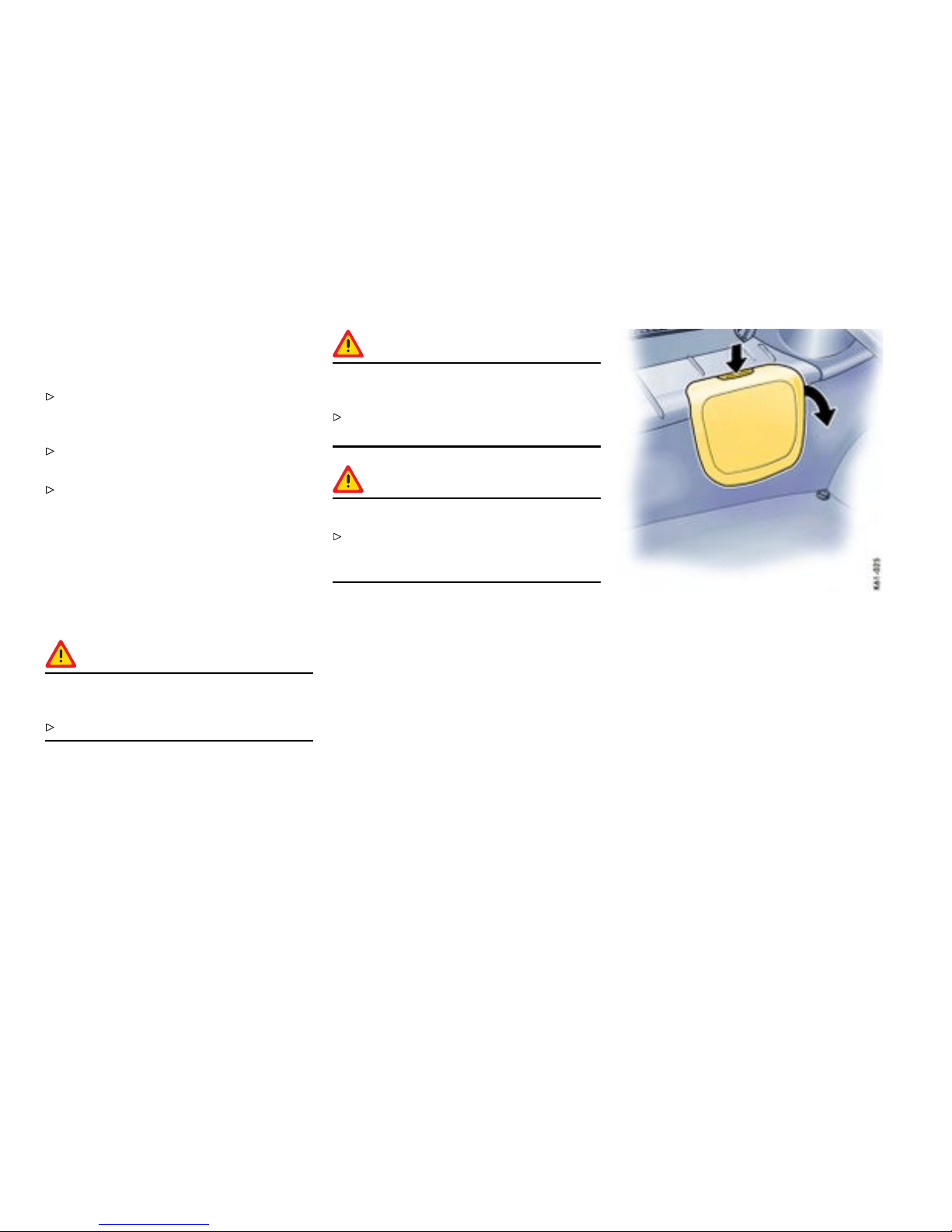
Engine Oil Level
Checki ng the oil level
Please observe the chapter ”EXERCISE
EXTREME CAUTION WHEN WORKIN G ON
YOUR VEHICLE” on p age 202.
Regularly check the oil level using the on-board
computer after the vehicle is refuelled.
Please obse rve the chapter ”OIL DISPLAY AND
MEASUREMENT OF THE ENGINE OIL LEVEL”
on page 131.
The difference between the minimum and max-
imum marks on the segment display is approx.
1.2 liters. Each segment of the display corre-
sponds to approx. 0.4 liter.
Topping off engine oi l
Warning!
Engine oil is hazardous to your health and
may be fatal if swallowed.
Keep engine oil out of children’s reach.
Warning!
Used engine oil contains chemical s that have
caused cancer in laborato ry animals.
Always protect your skin by washing thorough-
ly with soap and water.
Caution!
Risk of damage from overowing engine oil.
Take care while checking and topping up
engine oil not to soil the luggage compartment
or items of luggage.
The oil inlet o pening is in the rear luggage compart-
ment under the service flap.
1. The on-board computer indicate s how muc h oil
must be added.
2. Press catch button on the service flap and
open flap.
208Maintenance, Car Care
Downloaded from www.ManualsFile.com manuals search engine

3. Unscrew cap of the oil filler opening.
4. Add at most half a lite r of engine oil at a time.
5. Measure oil level again with the on-board
computer.
6. Add more engine oil if necessary. Never add
more engine oil than required to reach the
max. mark.
7. Close cap carefully.
8. Close service flap.
Maintenance, Car Care
209
Downloaded from www.ManualsFile.com manuals search engine

Engine Oil Recommendation
Recommended oil viscosity ranges dependent on ambient temperatures
Ambient temperature seasonal
SAE Viscosity Range engine oils
generally above -13°F /-25°C SAE 0W-40, 5W-40, 5W-50 approved by Porsche
genera lly below -13°F /-25°C SAE 0W-40 approved by Porsche
Suitable oi ls are:
Use only engine oils tested and approved by Porsche (Porsche approval list). Your athorized Porsche dealer will be pleased to advise you.
You will find a sticker in the service flap which provides information (manufacturer) about the initial factory filling of your engine.
Generally you can find the manufacturer suggestions on the oil containers or as a bu lletin on the market.
Oil change
The engine oil has to be ch anged at the i n tervals
listed in your Maintenance Schedule.
Please observe the chapter ”CAPACITIES” on
page 301.
We recommend that you have the engine oil
changed at your Pors che dealer, who has the
required oils and the necessar y filling equipment.
If you suspect an oil leak in th e engine have your
dealer check it out immediately.
All current engine oils are compatible with each
other, i. e. when making an oil change it is not
necessary to flush the engine if you wish to use a
different brand or grade of oil. Since, however,
each brand of oil has a special composition,
you should, if possible, use the same oil brand
if it becomes necessary to top up be tween oil
change s.
Porsche engines have long intervals between
oil changes. Yo u can make best use of these
long oil change intervals by using multigrade oils
since these are largely independent of sea sonal
fluctuations in temperature.
If your vehicle is used frequently in stop-and-go
traffic in cold weather, the engine will not always
be completely warmed up. Condensation from
products of combustion may accumulate in the
oil. In this case, it is advisable to change the oil
m
ore frequently so t h at your engine once again has
100% efficient oil.
Engine oil performance clas s
Engine oil is not only a lubricant, but also serves to
keep the engine clean, to neutralize the dirt which
penetrates into the engine through combustion
and to protect the engine against corrosion. To
perform these functions, the oil is provided with
additives which have been specially developed
for these functions. The efficiency of an oil is
expressed, for example, by the API, ILSAC or ACEA
classifications.
Viscos ity
Like all liquids, engine oil is vi scous when cold,
and thin-bodied when warm. The viscosity of an oil
is expressed by it s SAE class. For cold viscosity
(me
sured at temperatures below 32°F /0°C )
210Maintenance, Car Care
Downloaded from www.ManualsFile.com manuals search engine

the SAE class is given as a number and the l etter
”W“ (as in winter), for hot viscosity (measured at
212°F /100°C ) the SAE class is given only as a
numbe r.
The viscosity of an o il is, therefore, always the
same if it has the same number of an SAE class.
Oils with two viscosities are called multigrade oils;
oils with only one viscosity are termed single-grade
oils.
Single-grade oils cannot be used in your engine.
The viscosity of the engine oil for your Porsche has
to be selected according to the ambient tempera-
ture g iven in the engine oil recommendation table.
Maintenance, Car Care
211
Downloaded from www.ManualsFile.com manuals search engine
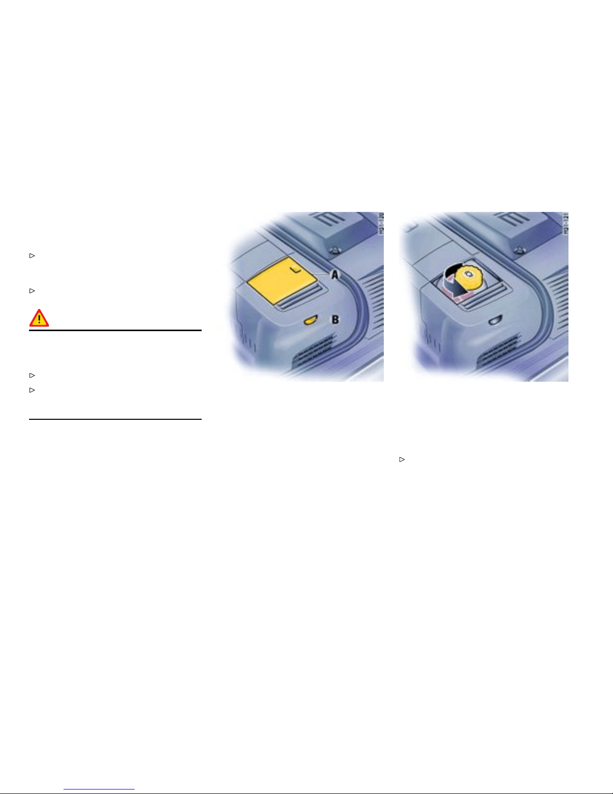
Brake F luid Level
Use of brak e uid
Please observe the chapter ”EXERCISE
EXTREME CAUTION WHEN WORKIN G ON
YOUR VEHICLE” on p age 202.
Use only new (unused) Original Porsche
brake uid.
Warning!
Brake uid is hazardous to your health, and
may be fatal if swallowed. Brake u i d also
attack s paintwork.
Keep brake fluid out of children’s reach.
Take care while topping off brake fluid not to
soil the luggage compartment or items of
luggage.
Check ing the brake uid level
The reservoir for the hydraulic braking and clutch
systems is in the front luggage compartmen t.
1. Open and remo ve cover flap A.
2. Regulary check the brake-fluid level on the
transparent expansion tank through the
window B. The fluid level should always lie
between the “Min” and “Max” marks.
A slight decrease i n the fluid level due to wear
and automatic readjustment of the disc brakes is
norma l. If, however, the fluid level falls markedly
or below the “Min” mark, the braking system may
have developed a leak.
Have the braking system checked immediatel y
at an authorized Porsche dealer.
Changing the brake uid
Brake fluid absorb s moisture from the air over
time. This accumulation of water lowers the boiling
point and, under certain operating conditio ns,
can affect the braking performanc e. Therefore
have the brake fluid changed in accordance
212Maintenance, Car Care
Downloaded from www.ManualsFile.com manuals search engine

with the change intervals stated in the brochure
“Mainte nance”.
Warning lights
Warning light USA
Warning light Canada
The brake-fluid warning lights in the instrument
panel and on-board computer indicate:
– brake-fluid level too low,
– in conjunction with large ped al travel, braking-
circuit failure.
If the warning lights should li ght up when
driving:
Stop immediately in a suitab le place.
Do not continue driving. Please have the fault
remedied at your nearest authorized Porsche
dealer.
Maintenance, Car Care
213
Downloaded from www.ManualsFile.com manuals search engine

Fuel Economy
Fuel economy will v ary depending on where,
when and how you drive, optional equipment
installed, and the general conditio n of your
car. A c ar tuned to specicat ions and correct-
ly maintained, will help you to achieve optimal
fuel economy.
Have your vehicle tuned to specifications. Air
cleaner should be dirt free to allow proper
engine “breathing”. Battery should be fully
charged. Wheels should be properly aligned.
Tires should be inflated to the correct pres-
sure.
Always monitor your fuel consumption.
Drive smoothly, avoid abrupt changes in speed
as much as possible.
Avoid jack rabbit starts and sudden stops.
Do not drive longer than necessa ry in the lower
gears. Shifting into a higher gear early without
lugging the engine will help save fuel.
Prolonged “warm up” idling wastes gas. Start
the vehicle just before you are ready to drive.
Accelerate slowly and smoothly.
Switch off the engine if stationary for longer
periods (traf fic lights, jams, level crossings).
Any additional weight carried in the vehicle
reduces fuel economy. Always keep cargo to a
minimum and remove all unnecessary items.
Organize your trips to take in se v eral errands
in one trip.
All electrical accessories contrib u te to
increased fuel consumption.
Only switch on the air co nditioning when
necessary.
The EPA estimate d miles per gallon (mpg)
is to be used for comparison purposes,
actual mileage may be different from the
estimated mpg, dependin g on your driving
speed, weather conditions and trip length.
Your actual highway mileage will probably be
less than the estimat ed mpg.
Please observe all local and national speed
limits.
214Maintenance, Car Care
Downloaded from www.ManualsFile.com manuals search engine

Operating your Porsche in other
Countries
Government regulations in the United States and
Canada require that automobiles meet specific
emission regulations and safety standards.
Therefore, cars built for the U.S. and Canada differ
from vehicles sold in other countries.
If you plan to take your Porsche outside the
continental limits of the United States or Canada,
there i s the possibility that
– unleaded fuel may not be available;
– unleaded fuel may have a considerably lower
octane rating. Excessive engine knock and
serious damage to both engine and catalytic
converters could result;
– service may be inadequate due to lack of
proper service facilities, tools or diagnostic
equipment;
– replacement parts may not be available or very
difficult to get.
Porsche cannot be responsible for the
mechanical damage that could result
because of inadequate fuel, service or parts
availabil ity.
If you purchased your Porsche abroad and want
to bring it back home, be s ure to find out about
shipping and forwarding requirements, as well as
current import and customs regulations.
Maintenance, Car Care
215
Downloaded from www.ManualsFile.com manuals search engine
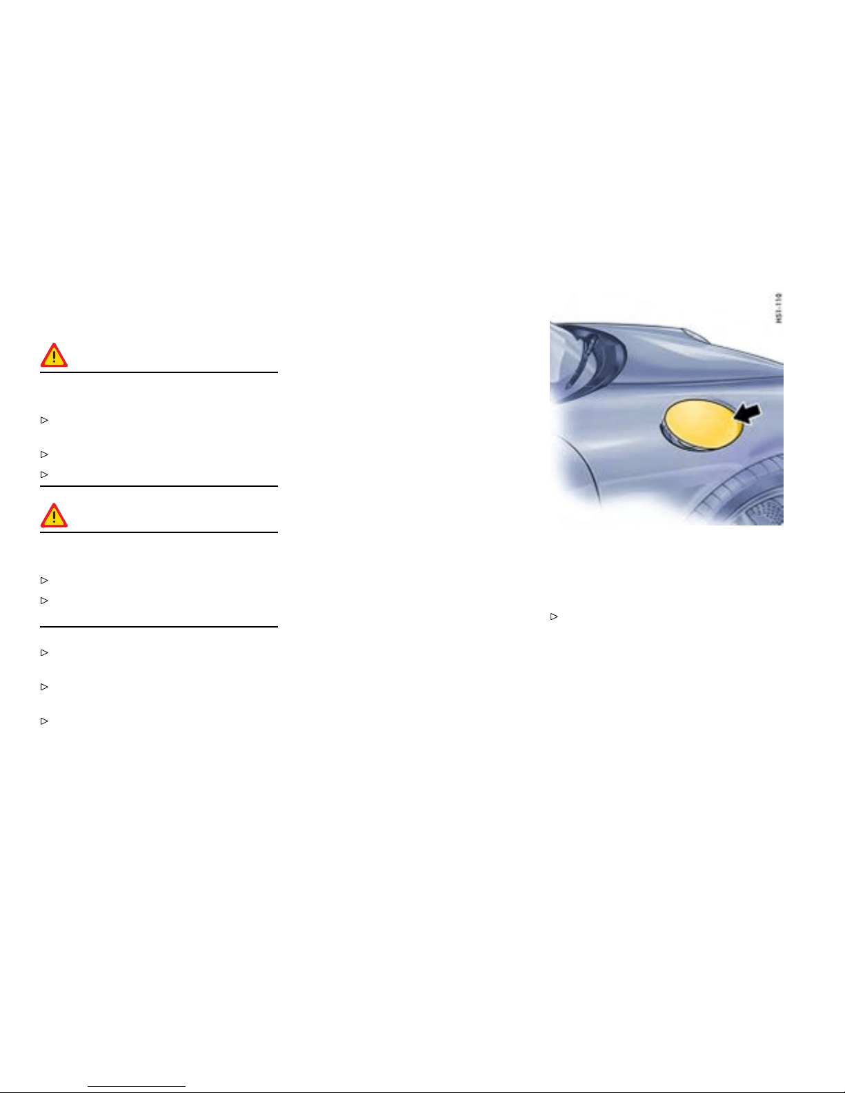
Fuel
Gener al information
Warning!
Fuel is highly ammable and harmful to
health.
Fire, open flame and smoking are prohibited
when handling fuel.
Avoid contact with skin or clothing.
Do not inhale fuel vapors.
Warning!
To prevent damage to the emission control
system an d engine:
Never drive the tank completely out of fuel.
Avoid high cornering speeds after the warnin g
lights have come on.
Please observe the chapter ”FUEL ECONOMY”
on page 214.
Please observe the chapter ”EMISSION
CONTROL SYSTEM” on page 220.
Please observe the chapter ”FUEL” on page
99.
Check engine warning light
If the warning lights in the instrument panel and
on-board compute r come on and remain on while
driving, it suggests:
– an improperly fastened tank cap or
– refueling with engine running.
Opening the ller ap
The filler opening is under the filler flap in the front
right fender.
With the vehicle unlock ed, press on the front
part of the filler flap (arrow) to open the flap.
The filler flap is centrally locked along with the
other locks.
216Maintenance, Car Care
Downloaded from www.ManualsFile.com manuals search engine

If there is a defect in the automatic unlocking
system:
Open the passenger door.
Pull the ring in the right-hand door aperture
(arrow).
Refuel ing
Fuel tank capacity
The fuel filling capacity is approx. 16.9 U.S.gal-
lons/64 liters.
Porsche does not recomm end the use of fuel
additives.
Fuel is highly ammable and harmful to
health .
Please observe the chapter ”CAPACITIES” on
page 301.
Procedu re
1. Important: Stop the engine and switch off the
ignition.
2. Slowly unscrew the tank cap . Hang the tank
cap on the plastic strap of the filler flap.
3. Insert fuel-hose nozzle fully into the filler neck
with the handle of the fuel-hose nozzle facing
down.
4. Do not add further fuel once the correctly
operate d automatic fuel-hose nozzle has
switche d of f. Fuel could spray or could run
over in warm temperatures.
5. Replace the tank cap immediate ly after
refueling and turn it until you hear it and feel
it engage.
If you lose the tank cap, you must replace
it only with an original part to reduce the
possibility of a re in the event of a collision.
Note
The oil level is aut omatically measured during
refuelling.
Please observe the chapter ”OIL DISPLAY AND
MEASUREMENT OF THE ENGINE OIL LEVEL”
on page 131.
Maintenance, Car Care
217
Downloaded from www.ManualsFile.com manuals search engine

Portable fuel containers
Danger!
Portable fuel containers, full or partia l ly
empty, may leak causing an explosion, or
result in re in case of an accident.
Never carry additional fuel in po rtable contain-
ers in your vehicle.
218Maintenance, Car Care
Downloaded from www.ManualsFile.com manuals search engine

Fuel Recommendat ions
Your Porsche is equipped with catalytic converters
and must use UNLEADED FUEL ONLY.
Your engine is d esigned to provide optimum
performance and fuel economy using unleaded
premium fuel with an oct ane rating of 98 RON
(93 CLC or AKI). Porsche therefore recommends
the use of these fuels in your vehicle.
Porsche also recognizes that these fuels may not
always be available. Be assured that your vehicle
will operate properly on unleaded premium fuels
with octane numbers of at least 95 RON (90 CLC
or AKI), since the engine’s ”Electronic Octane™
knock control“ will adapt the i gnition timing, if
necessary.
The use of UNLEADED FUEL ONLY is critical ly
important to the life of the catalytic convert-
ers. Deposits from leaded fuels will ruin the
converters and make it ineffe ctive as an emis-
sion control device.
Cars with catalytic conve rters have a smaller fuel
tank opening, and gas station pumps have smaller
nozzles. This will prevent accidental pumping of
leaded fuel into cars with catalytic converters.
Unleaded fuels may not be available outside the
contin ental U.S. and Canada. Therefore, we
recommend you do not take your car to areas
or countries where unleaded fuel may not be
available.
Octane ratings
Octane rating indicates a fuel’s ability to resist
detonation. Therefore, buying the correct octane
gas is important to prevent engine ”damage“.
The RON octane rating is based on the research
method . The CLC (U.S. Cost of Living Council
octan e rating ) or AKI (antiknock inde x) octane
rating usually displayed on U.S. fuel pumps is
calculated as research octane number plus motor
octane numbe r, div ided by 2, that is writ ten as:
RON + MON
R + M
2
or
2
The CLC or AKI octane rating is usually lower than
the RON rating:
For exampl e: 95 RON equals 90 CLC or AKI.
Fuels c ontaining a lcohol and ether
Some areas of t he U.S. require oxygenated fuels
during certain portions of the year. Oxygenated
fuels are fuels which contain alcohols (such as
methanol or ethanol) or ether (such as MTBE).
Under normal cond itions, the amount of these
compounds in the fuel will n ot affect driveability.
You may use o xygenated fuels in your Porsche,
provided the octane requirements for your vehicle
are met. We recommend, however, to change
to a different fuel or station if any of the followin g
problems occur with your vehicle:
– Deterio ration of driveability and performance.
– Substantially reduced fuel economy.
– Vapor lock and non-start problems, especially
at high altitude or at high temperature.
– Engine malfunction or stalling.
Fuels co ntaining M MT
Some North American fuels contain an octane
enhancing additive called methylc yclopentadienyl
manganese tricarbonyl (MMT).
If such fuels are used, your emission control
syste m performance may be negatively aff ected.
The check engine warning light on your instrume n t
panel may turn on. If this occurs, Porsche recom-
mends you stop using fuels containing MMT.
Maintenance, Car Care
219
Downloaded from www.ManualsFile.com manuals search engine
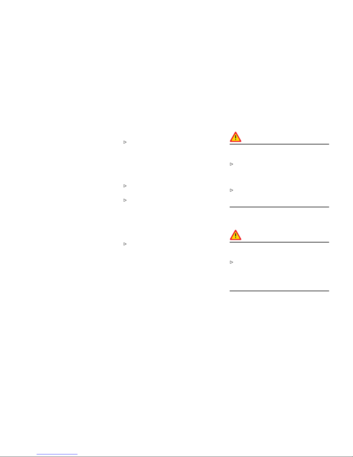
Emission Control System
In the interest of clean air
Pollution of our environment h as become a
problem that is of increasing concern to all of
us. We urge you to join us in our effor ts for cl eaner
air in controlling the pollutants emitted from the
automobile.
Porsche has developed an emission control
system that controls or reduc es those parts of the
emission that can be harmful to our environment.
Your Porsche is equipped with such a system.
Porsche warra nts the E mission Control System in
your new car under the terms and conditions set
forth in the Warranty Booklet.
You, as the owner of the vehicle, have the respon-
sibility to provide regular maintenance service for
the vehicle and to keep a record of all maintenance
work per f ormed. To facilitate record keeping, have
the service performed by authorized Porsche deal-
ers. They have Porsche trained technici ans and
special tools to provide fast and efficient service.
To assure efcient operation of the
Emissi on Control S ystem
Have your vehicle maintained properly and
in accordance with the recommendat i ons
described in your Maintenance Booklet. Lack
of proper maintenance, as well as improper
use of the v ehicle, will impair the function of
the emission control system and could lead to
damage.
Do not alter or remove any component of the
emission control system.
Do not alter or remove any device, such as
heat shields, switches, ignition wires, valves,
etc., which are designed to protect your
vehicle’ s emission control system. In addition
to serious engine damage, this can result in
a fire if excess raw fuel reaches the exhaust
system.
Do not continue to operate your vehicle if
you detect engine misfire or other unusual
operating conditions.
Parking
Warning!
Dange r of re resulting in s erious personal
injury or death.
Do not park or operate the vehicle in a reas
where the hot exhaust system may come in
contact with dry grass, brush, fuel spill or
other flammable material.
If your car catches on fire for any reason, call
the fire department. Do not endanger your life
by attempting to put out the fire.
Undercoating
Danger!
Dange r of re resulting in s erious personal
injury or death.
Do not apply additional undercoating or
rust-proofing on or near the exhaust manifold,
exhaus t pipes, catalytic converters or heat
shields. During drivi ng the sub stance used for
undercoatin g could overheat and ignite.
220Maintenance, Car Care
Downloaded from www.ManualsFile.com manuals search engine

How Em ission Control Works
When an automobile engine is running, it uses
energy generated through the combustion of a
mixture of air and fuel. Depending on whether a car
is driven fast or slo wly or whether the engine is cold
or hot, some of the fuel (hydrocarbons) may not be
burned completely, but may be discharged into the
engine crankcase or exhaust system. Additional
hydrocarbons may enter the atmosphere through
evaporation of fuel from the fuel tank. These
hydrocarbons (HC), when released into the air,
contribute to undesirable pollution.
In addition, carbon monoxide (CO) and oxides of
nitrogen (NOx) contribute to engine emissions.
They, too, are fo rmed during the combustion
process and discharged into the exhaust system.
To reduce these pollutants, your Porsche is
equipped with a precisely calibrat ed fuel injection
system to assure a finely balanced air/fuel mixture
under all operating condi tions.
Oxygen sensor
The oxygen sensor, insta lled in the exhaust
pipe continuously senses the oxygen content
of the exhaust and signals the informat ion to an
electronic control unit. The control unit c orrects
the air/fuel ratio, so the engine always receives an
accura t e l y metered air/fuel mixture.
Crankcase venti lation
Through crankcase ventilation, undesirable
emissions from the engine cran kcase are not
permit t ed to reach the outside atmosphere. These
emissions are recirculated from the crankcase to
the air intake system. From here the emissions
mix with the intake air and are later burned in the
engine.
Catalytic conver ters
The catalytic converters are efficient ”clean-up“
device s built into the exhaust system of the vehicle.
The catalytic conver ters burn the undesirable
pollutants in the exhaust gas before it is released
into the atmosphere.
The exclusive use of unleaded fuel is critically
important for the life of the catalytic convert-
ers. Therefore, only unleaded fuel must be
used.
The cata lytic converters will be damaged by:
– push or tow starting the vehicle ,
– misfiring of the engine,
– turning off the ignition while the vehicle is
moving or
– driving until the fuel tank is completely empty,
– by other unusual operati ng conditions.
Do not continue to operate your vehicle under
these conditi ons, since raw fuel might reach
the catalytic converters. This could result in
overheating of the converters. Federal law
prohibits use of leaded fuel in this car.
Maintenance, Car Care
221
Downloaded from www.ManualsFile.com manuals search engine

Fuel Evaporation Control
Fuel tan k ve nting
The evaporation chamber and the carbon canister
prevent fuel from escaping to the atmosphere at
extreme high outside temperatures, when driving
abruptly around curves and when the car is parke d
at an incline or in any other nonlevel position .
Vapor control system and storage
When the fuel tank is filled, vapors are collected
in the evaporation chamber by a vent line leading
the vapors to the carbon canister where they are
stored as long as the engine does not run.
Purge system
When the engine is running, the fuel vapors from
the canister will be mixed with f resh air from the
ambient air of the canister. This mixture will be
directed to the intake air housing by the tank vent
line, mixed with the intake air a nd burned during
normal combustion.
222Maintenance, Car Care
Downloaded from www.ManualsFile.com manuals search engine

Washer Fluid
Capacity
– Without headlight cleaning syst em: app roxi-
mately 2.6 quarts (2.5 liters).
– With headlight cleaning system: approximately
6.3 quarts (6 liters).
Washer uid
The reservoir, with a blue screw cap, is in the front
luggage compartment, to the rear left.
Clean water is generally not enough to clean
the windshield and headlights. Depending on
the season, mix the water with the appropriate
additives. Follow the instructions for the mixture
ratio.
Only use window cleaner concentrate which
meets the following requirements.
– Dilutability 1:100
– Phosphate-free
– Suitable for p lastic headlight lenses.
We recommend window cleaner concentrates
approved by Porsche. Your authorize d Porsche
dealer will be pleased to advise you.
Summer lling
Water + window cleaner concentrate at the mixing
ratio indicated on the container.
Winter lling
Water + an tifreeze protection + window cleaner
concentrate at the mixing ratio indicated on the
contain er.
Please note all the information on the contain-
ers of the window cleaner concentr ate or t he
antifreeze protection.
Adding wa sher uid
1. Please note all the in formation on th e refill
container of the cleaning agent.
2. Open cap of the washer-flui d reservoir (arrow).
3. Add washer fluid and close cap properl y.
Do not use engine coolant anti-freeze or any
other solution that can damage the car’s paint,
in the washer reservoir.
Warning light
If less than 0.52 quarts (0.5 liter) remains, a
warning messa ge appears on the on-board
computer.
Add washer fluid.
Maintenance, Car Care
223
Downloaded from www.ManualsFile.com manuals search engine

Power Steering
Warning!
Risk of accident resulting in serious person a l
injury or death. When the engine is stopped
(e.g. when being towed) or the hydraulic
system fails, there is no assistance for
steering. Therefore, substantially more force
will have to be exerted in order to steer.
Exercise great care when being towed.
Have the fault remedied at yo ur nearest
authorized Porsche dealer.
Note
The flow noise heard at full steering lock is system
related and does not indicate a defect in the
steerin g system.
Checking hydraulic uid
The reservoir is in the engine compartment.
Regular checking of h ydraulic fluid is part of
servicing.
Please observe the chapter ”EXERCISE
EXTREME CAUTION WHEN WORKIN G ON
YOUR VEHICLE” on p age 202.
224Maintenance, Car Care
Downloaded from www.ManualsFile.com manuals search engine

Filter
Air lter
The air filter is on the left-hand side of the engine
compartment.
A dirty air filter not only reduces engine perform-
ance, but can lead to prematu re engine wear.
Regular filter replacement is part of the routine
maintenance service.
In dusty conditions, check the filter element
more frequently and replace i f necessary.
Combination lter
The fresh air passing through the combination filter
into the passenger compartme nt i s virtually free of
dust, pollen, and unpleasant odors.
If the outside air is polluted by exhaust fumes,
press the circulating-air button.
A dirty filter can be the ca use of reduced air
throughput:
Have the filter replaced by an authorized
Porsche deal er.
Regular filter replacement is part of the routine
maintenance service.
Maintenance, Car Care
225
Downloaded from www.ManualsFile.com manuals search engine

Automatic Transmission Fluid
The torque converter and the transmission are
lubricated with Automatic Transmissio n Fluid (ATF).
The final drive requires transmission oil.
Please observe the chapter ”CAPACITIES” on
page 301.
Do not tow the car o r run the engine without ATF
in the transmission. The automati c transmission
may be damaged by even a tiny speck of dirt, only
a clean funnel or spout must be used when adding
ATF.
The ATF and transmission oil has to be checked
and changed at the intervals listed in your Mainte-
nance Schedul e.
We recommend that you have the ATF and trans-
mission oil changed at your Porsche dealer, who
has the required lubricants and the necessary filling
equipment.
If you suspect an oil leak in the transmi ssion,
have your authorized Porsche dealer check it o ut
immediately.
226Maintenance, Car Care
Downloaded from www.ManualsFile.com manuals search engine

Manual Transmission Oil
The transmiss ion oil ha s to be checked and
changed at the intervals listed in yo u r Maintenance
Schedule.
Please observe the chapter ”CAPACITIES” on
page 301.
We recom mend that you have the transmis sion
oil changed at your Porsche dealer, who has
the required lubri cants and the necessary filling
equip m ent.
If you suspect an oil leak in the transmission,
have your authorized Porsche dea ler check it out
immediately.
Maintenance, Car Care
227
Downloaded from www.ManualsFile.com manuals search engine

Car Care Instruct ions
Long-t erm maintenance of value
Please observe the chapter ”EXERCISE
EXTREME CAUTION WHEN WORKIN G ON
YOUR VEHICLE” on p age 202.
Regular and correct care helps to maintain
the value of your car and is also a precondi-
tion for the New Vehicle Warranty and the Anti
Corrosion Warranty.
Your authorized Porsche dealer has specially
developed car-care products from the
Porsche program available either singly or as
comple te car-care sets. They will be pleased
to help you select suitable products.
Whether you use Porsche products or other
comme rcially available cleaning agents rst
make sure of their correct application.
A Porsche that is well-cared for can look like new
for years. It all depends on the amount of care the
owner is willing to give the car.
Warning!
Risk of serious personal injury or damage to
the vehicle or property. Cleaning agents may
be hazardous to your health. Most chemical
cleaners are con centrates which require
dilution. High concentrat i ons might cause
problems ranging from irritation to serious
injury as well as damage to your vehicle.
Keep cleaning agents out of reach from
children.
Observe all caution labels.
Always read directions on the container
before using any product. These directions
may contain information necessary to avoid
personal injur y.
Do not use fuel, kerosene, naphtha, nail polish
remover or other volatile cleaning fluids. They
may be toxic, flammable or hazardous in other
ways. Only use spot removing fluids in a well
vented area.
Do not clean the underside of chassis,
fenders, wheel covers, etc., without protecting
your hands and arms as you may cut yourself
on sharp-edged metal parts.
Moisture and road salt on brakes may affect
braking eff i ciency.
Test the brakes after each vehicle washing .
Car washing
Washing
The best method of protecting your car from the
damaging effects of the environment is frequent
washing and the applicat ion of a preservative. The
underside of your vehicle should also be thoroughly
washed for cinders, salt or sanding at winter’s end.
The longer salt, road dust and industrial dust,
dead insects , bird droppings or substances from
trees (resin, pollen) are allowed to remain on the
bodywork, the more serious is their harmful effect.
New cars should be washed carefully with plenty
of clear water to protect the new paint work. Dark
paint finishes show up the smallest of surface
damage (e.g., scratches) more readily than lighter
colors.
Dark colors are also more susceptibl e to scratc h-
ing because of the composition of their pigments
and require particularly careful pa int care.
Do not wash your car in bright sunlight or while
the bodywork is still hot.
When washing by hand, use abundant water, a
soft sponge or wash brush, and Porsche car
shampoo.
Begin by spraying the body thoroughly with
water to rinse away loose dirt.
228Maintenance, Car Care
Downloaded from www.ManualsFile.com manuals search engine

After washing, rinse t he car with plenty of
water and then dry with a chamois leather. Do
not use the same chamois leather for drying
as you use for cleaning the windshield and
windows.
Warning!
Moisture which gets on to t he brakes during
a car wash can reduce braking efciency or
make the brakes pull unevenly which could
increase the danger of an accident, causing
serious personal injuries or death.
Always apply the brakes a few times after
washing the car to test braking efficiency and
dry the brake discs. When doing this, take
care not to hamper other road u sers behind
you (traffic conditions permitting).
Automatic car washes
Optional add-on parts or parts which project
beyond the contours of the vehicle may be
damaged by design features (e.g. brus hes) of
automa t i c car washes.
Wash and dry by han d all points not reached
by a car wash, such as door and lid seams or
door sills.
Please consult the operator before using
automatic car washes.
Please observe the chapter ”WIPER BLADES”
on page 203.
The following parts are particularly suscepti-
ble to damage:
– Windshield wipers (always switch them off
to prevent th em wiping unintentionally in
intermittent or sensor operation).
– Fixed rear spoiler or extended rear spoiler.
– Wheels (the wider the rim and the lower the tire
height, the greater the risk of damage).
– High-gloss wheels (to prevent these from
getting scratched, do not clean with the
wheel-cleaning brushes of the car wash).
– External antenna (always unscrew).
– Roof Transport System (always remove
comple tely).
Note
Automatic car washes spray water at odd angles
and high pressures, which are not seen in normal
driving. Therefore, water can sometimes find its
way into the passengers compartment during or
shortly after the car wash.
Door locks
To prevent the door locks from f reezing during
the cold season, the lock cylinders should be
covered during a wash.
Should the locks freeze, use an ordinary
de-icer. In many cases, a well warmed key
can help. N ever use excessive force.
Maintenance, Car Care
229
Downloaded from www.ManualsFile.com manuals search engine
Paint
Never rub a dusty car with a dry cloth since
dust particles are abrasive and could dull and
damage the surface finish.
The paintwork of your car is exposed to all types of
mech anical and chemical conditions, particu larly
climatic ones such as bright sunlight, rain, frost
and snow. Ultraviolet light, rapid changes in
temper ature, rain, snow, industrial dust and
chemical deposits constantly attack the paint
which is only able to withstand such exposure in the
long term if it is given regular care and attention.
Do not apply silicone polishes to the windows.
Do not treat matt-pai n ted component s with
preservatives or polishes as this will spoil the
matte effect.
Preservation
The paint surface becomes dull over time due to
weathering. It is therefore necess ary to preserve
the paint regularly.
This keeps the paint shiny and elastic. Dirt is
prevented from adhering to the paint surface and
industrial dust is prevented from penetrating the
paint.
Provided it is washe d an d treated with preservative
regularly, the brand new finish of y our vehicle will
be retained for years to come.
Simply apply paint preservative after washi ng
the vehicle and polish it smooth.
Polishing
Do not resort to using Porsche polish until it
becomes evident that the normal preservatives
no longer produce the desired finish.
Spots and stains
Remove tar stains, grease, oil spots and
dead insects as soon as possible with Insect
Remover. T hey can cause discoloratio n if
allowed to remain on the paintwork.
Wash the affected area immediate ly after
treating it.
Minor pai nt damage
Have minor paint damage, such as scratches,
scores or c hips caused by flying stones,
repaired immediatel y by your authorized
Porsche dealer before cor rosion sets in.
However, if there are already traces of corrosion,
they must first be removed carefully and thorough-
ly. Coat the area w ith a rust-proofing primer and
finish off with a top coat. The paint code and color
number are found on th e data bank in the Mainte-
nance bookle t and on the filler flap.
Cleaning and preserving en gine
compartment
The engine compartment and the surface of the
engine are treated with a corrosion-inhibitor at the
factory.
If degreasing solvents are used to clean the
engine compartment or the engine is washed
down, the process almost invariably removes the
corrosion-inhibiting coating. It i s then absol utely
necessary to have a durable preservative applied
to all s urfaces, body seams, joints and assemblies
in the engine compartment. This also applies when
corrosion-in hibitor parts are replaced.
Caution!
Risk of damage to the alternator.
Do not point the c leaning jet directly at the
alternator, or cover the a lternator.
Effective corrosion-proofing is particul arly impor-
tant during the cold weather season. If your car
is driven frequently in areas where salt has been
spread on the roads, the whole engi ne compart-
ment should be cleaned thoroughly after the winter
to prevent salt from causing any lasting damage. A
full under-body wash should also be performed at
the same time.
230Maintenance, Car Care
Downloaded from www.ManualsFile.com manuals search engine

Windows
The road dust which settles on the windshield
and windows contai ns particles of tire rub ber
and oil residue. The interior trim and upholstery
release particles, particul arly in strong sunlight,
which collect on the insides of the windows. These
deposits are au gmented by impurities in the air
which enters the car through the fresh air vents.
Clean all windows regularly, inside and outside,
with Porsche window clean er.
If you use a chamois leather for the windows,
do not use it for paintwork as it will otherwise
pick up a certain amount of preservative or
polish and could smear the windows and thus
impair vision.
Remove dead insects with the Porsche insect
remover.
Note
Door windows feature a water-repellent (hydropho-
bic) coating which prevents soiling of the windows.
This coating is subject to n atural wear and can be
renewed.
Consult an authorized Porsche dealer.
Wiper blades
Wiper blades tha t are in perfekt condit ion are vital
for a clear view.
Replace the wiper blades twice per year
(before and after the cold season) or whenever
wiper performance deteriorates.
Periodically clean the wiper blades with
Porsche window cleaner, especially after the
vehicle has been washed in a car wash. If they
are very dirty (e.g. with insect remains), they
can be cleaned with a sponge or cloth.
Undercoating
The underside of your car is d u rably protected
against chemical and mechanical influe nces.
As it is not possible to exclude the risk of damage
to this protective coating in day to day driving,
it is advisable to have the underside of the car
inspected at certain intervals - preferabl y before
the start of winter and again in spring - and the
undercoating restored as necessary.
Your a uthorized Porsche deale r is familiar with
the bodyseal treatment procedures and has
the necessary equipment for applying factory
approved materials. We recommend that you
entrust them with such work and inspection s.
Unlike conventional spray oils, undercoating and
rust-proofing compounds based on bitumen or wax
do not attack the sound-proofing materi als applied
at the factory.
Warning!
Dange r of re resulting in s erious personal
injury or death.
Do not apply additional undercoating or
rust-proofing on or near the exhaust manifol d ,
exhaust pipes, catalytic converters or heat
shields. During driving the substance used for
undercoating could overheat and ignite.
Before applying fresh underseal, carefully
remove deposits or dirt and grease. Once it
has dried, the new undercoating compound
forms a tough protective coating which
provides efficient rust-proofing of the floor
panels and components.
Always apply a fresh coating of suitable
preservative to unprotected areas after
cleaning the underside of t h e body, the
transmission, the engine or carrying out
repairs to under-body, eng ine or t ransmission
components.
Effe c tive rust-proofing is particul arly important dur-
ing the cold weather season. If your car is dri v en
frequently in areas wh ere salt has been spread
on the roads, the whole engine compartment
should be cleaned thoroughly after the winter to
prevent salt from causing any lasting damage. A
full under-body wash should also be pe rfor med at
the same time.
Maintenance, Car Care
231
Downloaded from www.ManualsFile.com manuals search engine
Door, lid and window seals
Wash dirt (e.g. abrasion, dust, road salts) from
all seals regularly using warm soapy water.
Do not use any chemical cleaning agents or
solvents.
When there i s a frost hazard, the outer door seals
and the front and rear lid seals can be protected
against freezing into place by a suitable care
product.
In order to prevent damage to th e ant i-friction
coating, the inner door seals must not be
treated with care produc t s.
Stainless steel exhaust tailpipes
Stainless steel exhaust tailpipes can discolor due
to soiling, strong heat, and combustion residues.
The original polish can be achieved again using
commercially available metal polishing paste or
metal polish.
Headl ights, lights, interior and exterior
plasti cparts, adhesive lm s
Use only clean water and a little dishwashing
detergent to clean light lenses, plastic
headlight lenses, plastic part s and surfaces.
Do not clean when dry. Use a soft sponge or
a soft, lint-free clo th. Gently wipe the surface
without applying too much pressure. The
Porsch e inside window cleaner is also s uitable
for cleaning plastic surfaces. Follow the
cleaning instructions on the container. Never
use other chemical cleaners or solvents.
Rinse cleaned surfaces with clear water.
Light alloy wheels
Please observe the chapter ”WASHING” on
page 228.
Warning!
Danger of accident resulting in serious
personal inju ry or death if cleaning agents
(e.g. wheel cleaning agents) come into
contact with the brake discs. The resulting
lm on the brake discs can impair braking
performan ce.
Make sure that no cleaning agent comes into
conta ct with the brake discs.
If cleaning agent has come into contact with
the brake discs, thoroughly clean the brake
discs with a strong jet of water.
Paying attention to any road users behind you,
dry the brake discs by applying the brakes at
short intervals.
Pitting may occur if metallic particles which cause
contac t corrosion (e.g. brass or copper in brake
dust) are allowed to remain on the aluminum for too
long.
If possible, wash the wheels with a sponge or
wash brush about every two weeks. In areas
where salt is spread on winter roads or there
is a lot of airborne industrial dust, it is best to
clean the wheels weekly. The Porsche Light
Alloy Wheel Cleaner (ph-value 9.5) can be
used for this purpose. If the ph-value of
the detergent is incorrect, the protective
coating on the wheels will be destroyed.
Polishes which dissolve oxides, such as those
frequently used for other metals, or abrasive
tools or agents are unsuitable beca use they
break down the oxide lm of the protective
coatin g and will cause discoloration of the
wheel.
Every three months, after cleaning, coat the
wheels with a car wax or non-corrosive grease
(vaseli ne).Using a clean cloth thoroughly rub
the grease into the surface.
232Maintenance, Car Care
Downloaded from www.ManualsFile.com manuals search engine

Leathe r
Characteristics and s pecial features
The natural surface markings of leather, e.g.
creases, healed scars, insect sting marks,
structural differences and slight variations in shade
and grain add to the attractivenes s of the natural
leather product.
A special mention must be made here of natural
leather.For natural leather, carefully selected hides
of the highest quality are used . It is not covered
completely with dye on producti on. “Nature’s
signature” is therefore easily recognizable. This
fine material is distinguished by a n outs tanding
seating comfort, special suppleness and a typical
patina.
Leather care and treatment
Clean all types of leather regularly to remove
fine dust using a soft, damp, white woolen
cloth or a commercially available microfiber
cloth.
Remove heavy c ontamination with Porsche
leather clean er. Please always follow the
instructions for use given on the c ontainers.
Caustic cleaners and hard cleaning object s
must not be used.
Per forated leather must under no circum-
stances get wet on its revers e side.
Once cleaned, leather (partic ularly the heavily
stressed leather seats) must be treated only with
Porsche leather care liquid.
Fabric, upholstery, carpets and oor-mats
Use only a vacuum cleaner or a medium stiff
brush.
Remove stains and spots with Porsche stain
remover.
The Porsche range of accessories includes
nonskid floor-mats to protect the c a rpets in
summer and winter.
Warning!
Risk of an accident resulting in serious
personal injury or death.
Always check the movement of the pedals
before driving and make sure that they are not
obstructed by a floor mat or any other object.
Secure the floor mat to prevent it from sliding
into positions that could interfere w ith the safe
operation of your vehicle - do not lay them
loosely in the vehicle. Your Porsche dealer will
be glad to offer you nonskid-floor mats of the
correct size.
Alcantara
Regular care
Do not use a leather care product to clean
Alcantar a.
For regular c are it is sufficient to clean the cover
with a soft brush.
Heavy abrasion or rubbing when cleaning causes a
perman ent change in the surface.
Cleaning when lightl y soiled
Wet a sof t cloth with water or a neutral soap
solution and wipe off the dirt.
Cleaning w hen heavily soiled
Wet a soft cloth with lukewarm water or
thinned white spirit and dab the dirt from the
outside in.
Safety belts
If it be comes necessary to clean the belts, you can
use any mild washing agent. Allow the belts to dry
prior to retracting, but avoid direct sunlight.
Only use suitable cleaners. If unsuitab le
cleaners are us ed or any attempt is made
to dye or bleach the belts, the webbing may be
weakened and thus constitute a safety risk.
Maintenance, Car Care
233
Downloaded from www.ManualsFile.com manuals search engine

Storing your Porsche
If you intend to s tore your Porsche for a prolonged
period, please consult your a uthorized Por sche
dealer. The staff will be glad to advise you on the
most suitable and neces sary methods.
Clean your vehicle thoroughly inside and
outside. Clean the engine compartment.
The under carriage and chassis components
should be free of dirt and salt deposits.
Fill up the fuel tank.
Change the oil and oil filter, and run the engine
for several minutes .
Increase the tire pressure to 58 psi (4 bar). It
is not recom mended to lift the vehicle, due to
the possibility of corrosion on shock absorber
piston shafts. The vehicle should be moved
slightly, approxim ately every four weeks, to
prevent flat spot on the tires.
Climate control
The air conditioning system should be in good
working condition and fully charged.
Windshiel d/Headlight washer
Check and correct antifreeze/cleaning
solution level as necessary.
Electrical system
Remov e the battery from the vehicle and store
it in a cool dry place, not on a cement floor.
When the battery is dis c onnected, the
alarm system is deactivated.
Recharge the battery every 3 m onths. If the
battery remains in the vehicle with the cables
connected, it is necessary to check, remove
and recharge the battery every 2-3 weeks. Do
not fast charge t he battery.
Please observe the c hapter ”BATTERY” on
page 262.
Vehicle interior
The interior must be dry, especially in the area
of the floor carpets. The use of drying agents
(Silica-Gel) is recommended in vehicles with
leather interi or and in areas with high humidity. The
recommended amount is 3 fabri c bags of 1.1 lbs.
(500 grams) each placed on the floor carpets.
Windows, doors, lids and top must be closed. The
air vents should be opened.
234Maintenance, Car Care
Downloaded from www.ManualsFile.com manuals search engine

Practic al Tips, Em ergency Service
Exercise Extreme Caution when Working on your
Vehicle ......................................... .............. 236
Tires/Wheels .............................................. 237
Loading Information .......................... ........... 248
Flat Tire ...................................................... 250
Wheel Bolts ................................................ 254
Changing a wheel ........................ ............ .... 255
Spacers ..................................................... 257
Electrical System ....................................... . 259
Battery ................... .................................... 262
Emergency Starting with Jumper Cables ........ 267
Replacing bulbs ........................................... 269
Headlights .................................................. 271
Turn signal light ........................................... 275
Side marker light ......................................... 278
Tail light ...................................................... 279
Additional brake light ............................... .... 280
License plate lights ...................................... 281
Front luggage compartment/ footwell lights .... 282
Door guard/curb/rear luggage compartm ent
lights ......................................................... 283
Adjusting Headlights ......................... ........... 284
Towing .............. ......................................... 287
Practical Tips, Emergency Service
235
Downloaded from www.ManualsFile.com manuals search engine

Exercise Extreme Ca u t ion when
Working on your Vehicle
Danger!
Ignoring the fo llowing instructions may cause
serious personal injury or death.
The engine compartment of any motor vehicle
is a potentially hazardous area. If you are not
fully familiar with proper repair procedures, do
not attempt the adjustments described on the
following pages. This caution applies to the
entire vehicle.
Only work on your vehicle outdoors or in a well
ventilated area.
Ensure that there are no open flames in
the area of your vehicle at any time when
fuel fumes might be present. Be especially
cautious of such devices such as hot water
heaters which ignite a flame intermittently.
Before working on any part in the engine com-
par tment, turn the engine off and let it cool
down sufficiently. Hot engine compartment
components can burn skin on contact.
Be alert and cautious around engine at all
times while the engine is running. If work has
to be performed with the engine running,
always set the parking brake, and make sure
the shift lever is i n neutr al or the selector lever
is in position P or N.
In particular, be very careful to ensure that
items of clothing (ties, shirt, sleeves etc.),
jewelry, long hair, hand or f ingers cannot get
caught in the engine-compartment blower, fan,
belts or other moving parts. The radiator and
radiator fans are in the front of t he car. The
fans can start or continue running as a functi on
of temperature, eve n with the engine switched
off. Carry out work in these areas only with the
engine off and exercise extreme caution.
Your Por sche is equipped with an electronic
ignition system. When the ignition is on,
high voltage is present in all wires connected
with the ignition syste m ; therefore, exercise
extreme caution when working on any part of
the engine while the ignition is on or the engine
is running.
Always support your car with safety stands if it
is necessary to work under the car. Jacks are
not suitable for this kind of work.
When workin g under t he car without safety
stands but with the wheels on the ground,
make sure the car is on level ground, the
wheels are blocked, and that the engine
cannot b e started. Remove the ignition key.
Do not smoke or allow an ope n flam e around
the battery or fuel. Keep a fire ext inguisher
close at hand.
Incomp lete or improper servicing may cause
problems in the operation of the car. If in
doubt about any servicing, have it done by
your authorized Porsche dealer. Improper
maintenance during the warranty period may
affect your Porsche warranty cover- age.
Supplies of fluids, e.g. engine oil, brake fluid
or coolant, are hazardous to your healt h . Keep
these fluids out of children’s reach and dispose
of them in accordance with the appropriate
regulations.
Some countries require additional tools and
special spare parts to be carried in your
vehicle . Please make enquiries before driving
abroad.
Worki ng in the engine compar tment
Have the necessary work in the engine compart-
ment done by a q ualified special ist workshop. We
recommend that you use your authorized Porsche
dealer for carrying out this work.
236Practical Tips, Emergency Service
Downloaded from www.ManualsFile.com manuals search engine
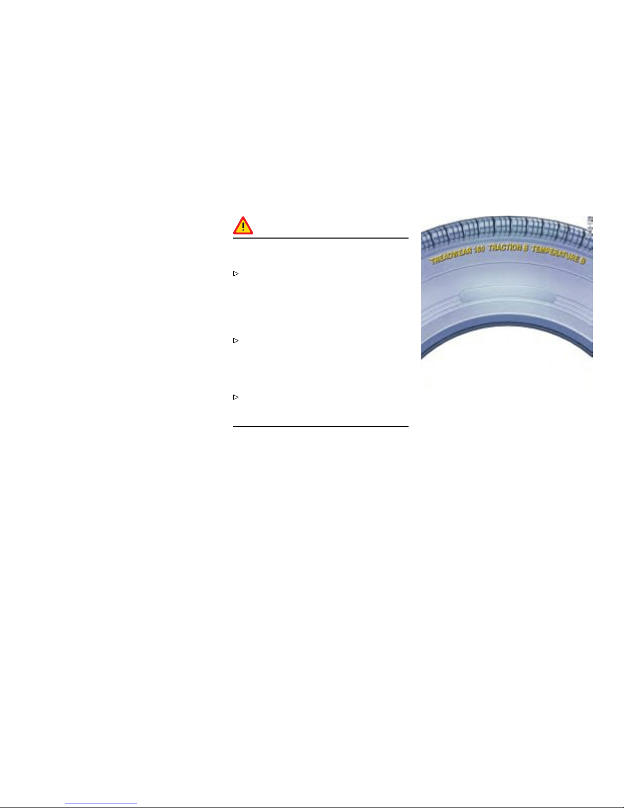
Tires/Wheels
The original equipment tires and wheel rims on
your Porsche comply with all applicable Federal
Motor Vehicle Safety Standards.
For your safety remember the following:
– Wheel rims and wheel bolts are matched to fit
your Porsche.
– If you intend to use other than original equip-
ment wheels, be sure th at they conform to
Porsche spec ifications for your model. Only
tires w ith the same make and with the same
specification code (e.g. “N0”, “N1”...) can be
mounted.
– The use of wheel rims and wheel bolts that
do not meet specifications of the original
factory installed equipment will affect the safe
operati on of your vehi cle.
– Before you plan on exchanging wheels, or
snow tires already mounted on the wheel rims,
consult your authorized Porsche dealer. Your
dealer has the technical information necessary
to advise you which wheel rims and wheel
bolts are com patible with the original factory
installations.
Danger !
Risk of loss of control and serious persona l
injury or death.
If while driving, your vehicle experiences a
sudden vibration or ride disturbance, and/or
you suspect that possible dama ge to your
tires or vehicle has occurred, you shou ld
immediately reduce your speed without
excessive use of the brakes.
Stop the vehicle as soon as possible, and
inspect the tires. I f you canno t deter mine the
cause for the disturbance, have your vehicle
towed to the near- est Porsche or tire dealer to
have your vehicle or tire(s) inspected.
Continuing to operate the vehicle without
correction could result in a loss of control and
serious personal injury.
Example
Uniform Tire Quality Gradin g
Quality grades can be found where applicable
on the tire sidewall between tread shoulder and
maximum section width.
All passenger car tires mus t conform to Federal
Safety Requirements in addition to these grades.
Treadwea r
The treadwear grade is a comparative rating based
on the wear rate of the tire when tested under
controlled conditions on a specific government
test course. For example, a tire graded 150 would
Practical Tips, Emergency Service
237
Downloaded from www.ManualsFile.com manuals search engine

wear one and a hal f (1-1/2) times as well on the
government course as a tire graded 100. The
relative perfor mance of tires depends upon the
actual conditions of their use, however, and may
depart significantl y from the norm due to variations
in driving habits, service practices and differences
in road characteristics and climate.
Traction AA, A, B, C
The traction grades , from highest to lowest, are
AA, A, B and C and they represent the tire’s ability
to stop on wet pavement as measured under
controlled conditions on specified government test
surfaces of asphalt and concrete. A tire marked C
may have poor traction performance.
Warning!
The traction grade assigned to this is based
on braking (straight-a h ead) traction tests and
does not include cornering (turned) traction,
acceleration, hydroplaning or peak traction
characteristics.
Temperature A, B, C
The temperature grades are A (the highest), B
and C, representing the tire’s resistance to the
generation of heat and its ability to dissipate
heat when tested under controlled conditions on
a specified indoor laboratory test wheel. Sustained
high temperatures can cause the material of
the tire to degenerate and reduce tire li f e, and
excessi ve temperature can lead to sudden tire
failure. The grad e C corresponds to a level of
performance which all passenger car tires m ust
meet under the Federal Motor Vehicle Safety
Standard No. 109. Grades B and A represent
higher levels of performance on the laboratory test
wheel than the minimum required by law.
Warning!
The temper ature grade for this tire is estab-
lished for a tire that is properly i nflated and
not overloaded. Excessive speed, underinfla-
tion, or excessive loading, either separately
or in combinati on, can cause heat buildup and
possible tire failure, resulting loss of control,
leadin g to serious personal injury or death.
Tire pressures
Warning!
Incorrect tire pressure ca uses increased
tire wear and adversely affects road han-
dling. This could lead to tire failure, result i ng
in loss of control, leading to serious personal
injury or death.
Always use an accurate tire pressure gauge
when checking inflation pressures.
Do not exceed the maximum tire pressure
listed on the tire sidewall.
Please observe the chapter ”TIRE PRESSURE
PLATE” on page 240.
Cold tire infl ation pressure means: all tires
must be cold, ambient temperature m aximum
(68°F /20°C ), when adjusting the inflation
pressure. Avoid sunlight striking the tires
before measuring cold pressures, since
the pressures would rise from temperature
influenc e.
Valve caps protect the valve from dust and
dirt, and thus from leakage. Always screw
caps tightly down. Replace missing caps
immediately.
Use only plastic valve caps.
238Practical Tips, Emergency Service
Downloaded from www.ManualsFile.com manuals search engine
Do not use commercially available sealant
or tire inflating bottles. Only use Porsche
approved tire sealant.
Please obse rve the chapter ”TIRE PRESSURE
FOR COLD TIRES” on page 299.
Each tire, including the spare (if provided),
should be checked every 2 weeks when cold
(68°F /20°C ) and inflated to the inflation pres-
sure recommended in this Owner’s Manual or on
the tire-pressure plate. If your vehicle has tires of a
different size than the size indicated in this Owner’s
Manual or on the tire-pressure plate, you should
determine the p roper tire inflation pressure for
those tires.
As an added safety feature, your vehicle has been
equipped with a tire pressure monitoring (TPC) that
illuminates a low tire pressure message when one
or more of your tires is significantly under-inflated.
Accordingly, when the low tire pressure message
illumina tes, you should stop and check your tires
as soon as possible, and inflate them to the proper
pressure. Driving on a significantly under-inflated
tire causes the tire to overheat and can lead to tire
failure. Under-inflation also reduces fuel efficiency
and tire tread life, and may affect the vehicle’s
handling and stoppi ng ability.
Please note that the TPC is not a subs titute for
proper tire maintenance, and it is the driver’s
responsibility to maintain correct tire pressure,
even if under-inflati on has not reached the level to
trigger illumination of the TPC low tire pressure
message.
On vehicles with tire pressure monitoring:
Please obse rve the chapter ”TPC TIRE
PRESSURE MONITORING” on page 122.
When tires are wa rm, the tire pressure is
increased.
Never let air out of hot tires. Th is could cause
the tire pressure to fall below the prescribed
value.
Insufficient tire filling pressure can cause tires to
overheat and thus be damaged - even invisibly. Hid-
den tire damage is not el iminated by subsequently
correcting the tire pressure.
Overloadi ng
Danger !
Risk of damage to vehicle parts, loss of
control and serious personal injury or death.
Do not overload your vehicle. Be careful about
the roof load .
If loading the vehicle also correct the tire
pressure. Tire pressure for loaded vehicle
can be found on the tire pressure plate and in
the chapter techni cal data.
Never exceed the specified axle load. Over-
loading can shorten the service life of the tires
and car, as well as lead to dangerous vehicle
reactions and long braking distances. Damag e
due to overloading is not covered by the vehi-
cle warranty.
Please observe the chapter ”LOADING
INFORMATION” on page 248.
Please observe the chapter ”TIRE PRESSURE
FOR COLD TIRES ” on page 299.
Practical Tips, Emergency Service
239
Downloaded from www.ManualsFile.com manuals search engine
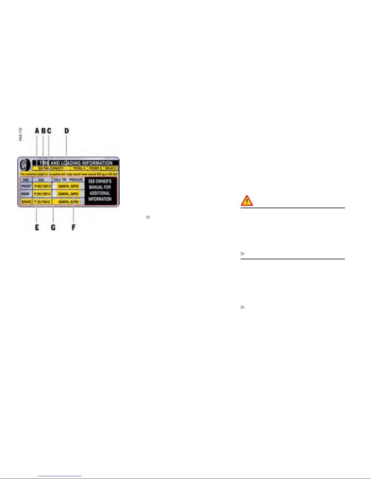
Example of a tire pressure plate
Tire pressure plate
Information on the tire pressure plate
A
Seating capacity
Maximum number of vehicle occupants,
including the d river.
B Vehicle load limit
Is the maximum total weight limit
specif ied of the load (passengers
and cargo) for the vehicle. This is the
maximum weight of passenge rs and
cargo that can be loaded into the vehicle.
Please observe the chapter
”LOADIN G INFORMATION” on page
248.
C Tire size for the front axle
Check with your authorized Porsche
dealer abo u t the current release status.
D
Recommended tire pressure for the front
axle
These values are for cold tires
(68°F /20°C ).
E
Tire size for the rear axle
Check with your authorized Porsche
dealer abo u t the current release status.
F
Recommended tire pressure for the rear
axle
These values are for cold tires
(68°F /20°C ).
G
In vehicles with collapsible spare wheel:
Size and tire pressure of th e spare
wheel.
Tire traction
Warning!
When driving on wet or sl u shy roads, a wedge
of water may build up between the tires
and the road. This phenomenon is known
as “hydroplane” and may cause partial or
complete loss of traction, vehicle cont rol or
stopping ability.
Reduce spee d on wet surfac e to prevent this.
Tire life
Tire life depends on various factors, i. e., road
surfaces, traffic and w eather conditio ns, driving
habits, type of tires and tire care.
Inspect your tires for wear and damage before
driving off. If you n otice uneven or substantial
wear, wheels might need alignment or tires
should be balanced or replaced.
240Practical Tips, Emergency Service
Downloaded from www.ManualsFile.com manuals search engine
Tire wear
The original equipment tires on your Porsche have
built-in tire wear indicators. They are molded into
the bottom of the tread grooves and will appear as
approximately 1/2 in. (12 mm) bands when the tire
tread depth is down to 1/16 of an in. (1.6 mm).
When the indicators appear in two or more
adjacent grooves, it is time to replace the tires.
We recom m end, however, that you do not let the
tires wear d own to t his extent. Worn tires cannot
grip the road surface properly and are even less
effective on wet roads.
In the United States, state laws may govern the
minimum tread depth permissib le. Follow all su ch
laws.
Danger!
Driving on worn tires can result in loss of
control of the veh i cle and could cause serious
personal injuries or death.
Do not drive with worn tires or tires showing
cuts or bruises as they may lead to sudden
deflation and loss of control w hich could cause
severe personal injury.
Special ized high performance tires on high
performance sports cars exhibit more wear
than those on a family sedan, or even a high
performance sedan. Therefore, it is important
to check your tire pressure and condition at
least every two weeks.
If you notice that tires are wearing unevenly,
consult your Porsche dealer. Uneven wear may
not always be due to im proper wheel alignmen t. It
can be the result of individual driving habit s such as
cornering at high speeds. I f the tire p ressure is not
checked and adjusted regularly, abnormal tire wear
can also occur.
Tire car e
Avoid damaging tires and wheel rims.
If you must drive over a curb or other obstacle,
drive slowly and at an obtuse angle.
Check tires for uneven wear and damage
before driving off.
Remove imbedded material.
Replace worn or damaged tires immediately.
Keep oil, fuel, brake fluid, etc. away from tires.
Replace missing valve stem caps.
Keep tires in flated correctly.
Wash tires w hen washing the vehicle. Also
clean inner side of wheels.
Do not use abrasive cleaners when washing
the wheels.
Check wheel rims for corrosion.
Remove road salt, if driving in winter.
Tire damage, puncture
Check tires for imbedded material, cuts,
punctu res, cracks and bulges (side wall)
before driving off.
In case of tire dam age, where it is uncertain
whether there is a break in the ply with all its
consequ ences or tire damage caused by thermal
or mechanical overloading due to loss of pressure
or any other prior damage, we recommend that the
tire be replaced for safety reasons.
If one faulty tire is replaced it should be noted that
the difference in tread depth on one axle must not
exceed 30 %. Han dling inconsistencies may result.
Perform a visual inspection if necessary.
Danger!
Risk of serious personal injury or death.
Driving the vehicle with low tire pressure
increases risk of a tire failure and resulting
loss of control. Furthermore, low tire pressure
increases rate of wear of the affected tires.
Check tires - inclu ding sidewalls - regularly for
foreign bodies, nicks, cuts, cracks and bulges.
Practical Tips, Emergency Service
241
Downloaded from www.ManualsFile.com manuals search engine

After driving off road, examine tires for si gns
of damage such as cuts, tears, bulges or
foreign objects stuck in the t read. Replace a
damage d tire if necessary.
Cross curb edges slowly and at right angles
if possible. Avoid driving over steep or sharp
curbs.
In cases of doubt, have the wheel (particularly
the inner side) checked by an authorized
Porsche dealer.
Tire replaceme nts
If in doubt, contact your Porsche deale r. Use only
tire makes and types approved by Porsche.
If you do not use a Porsche recommende d
replacement tire, make sure that you pur-
chase your new tires from a reputable tire
dealer and that the dealer complies with all
manufacturers warnings for those tires.
Only tires with the same make and with the
same specication code (e.g. “N0”, “N1”...)
can be mounted.
Before mounting new tires, check with your
Pors che dealer about the current release
status.
Use tires with “ZR” quality standards. There a re
currently no standards concerning tire strength at
speeds above 150 mph (240 km/h).
Tires should be replaced no less than on one axle
at the time. Only tires of the same make and type
must be used. Mixed tires are not permissible.
Initially, new tires do not have their full traction. You
should therefore drive at modera te speeds during
the first 60 - 120 miles (100 - 200 km).
If new tires are installed only on one axle, a
noticeable change in handling occurs due to
the different tread depth of the other tires. T his
happens especially if only rear tires are replaced.
However, this condition disappears as the new
tires are broken in.
Please adjust your driving style accordingly.
Installation of new tires should only be done by a
qualified tire technician.
Valves
Rubber valve stems must be replaced every time
a tire is replaced. For metal valves, the installation
and replacement instructions must be o bserved .
Use only genuine Porsche metal valves.
Protect the valve inserts against soiling with
valve caps. Soiled valve inserts can cause a
gradual loss of air.
Use only plastic valve caps.
Parking at the curb
Warning!
Hard impacts against curb s (or trafc islands)
are dangerous and may cause hidden tire
damage which is not noticeable until later.
Such damag e can result in accidents at high
speeds causing serious personal injury or
death. Depen ding on the force of impact , the
edge of the rim can also be damaged.
If you are in doubt, have the wheel checked by
an expert, particularly if you suspect damage
on the inside.
242Practical Tips, Emergency Service
Downloaded from www.ManualsFile.com manuals search engine

If you must drive over a curb or ot her obstacle,
drive slowly and at an obtuse angle. Exercise
care when parking along curbs.
Wheel alignment, wheel balancing
As a precaution, have wheels with summer
tires balanced in the spring, and those with
mud and snow tires before winter. Unbalanced
wheels may affect car handling and tire life. Onl y
the specified weights may be used for wheel
balanc ing. Self -adhesive weights must not come
into contact with cleaning agents, since they could
drop off. Uneven tread wear indicates wheel
imbala nce. In this event, the vehicle should be
checked at an authorized Porsche dealer.
Warning!
If, during a trip, uneven running or vibrations
occur that could be caused by damage to
tires or the car, the speed must be reduced
immediately, but without braking sharply.
If you continue your trip without having the
cause of the fault remedied, you might lose
control of your vehicle which could cause
serious perso nal injury or death.
Stop the vehicle and check the tires.
If no cause for the fault can be found, drive
carefully to the nearest au thorized Porsc he
dealer.
Removing and storing tires
After changing, adjust tire pressure and torque
wheel bolts diagonally to 94 ft.lb. (130 Nm).
Tires must always remain on the same side
of the vehicle. When wheels are removed,
the direction of rotation and positio n of each
wheel should be marked.
Example
FR (front right), FL, RR and RL.
Wheels must always be fitted in accordance with
their marking.
The perception that tire durability and performance
are immune to the effects of storage and age
is unfounded. Chemical additives, which make
the rubber elastic, lose their effectiveness in the
course of time and the rubber becomes brittle and
cracks.
Therefore, the tires should be inspected from
time to time.
Note
Under no circumstances should tires older than 6
years be used on your Porsche.
The age of the tire can be obtained from the
“DOT” code number. If, for example, the last four
numbers read 0706, then the tire was produced in
the 7th week of 2006.
Store tires in a cool and dry place.
Practical Tips, Emergency Service
243
Downloaded from www.ManualsFile.com manuals search engine

Snow tire s
For a b etter grip on snow and ice, use radial M+S
tires with studs. Che ck with your local M otor
Vehicle Bureau for possible restrictions.
Danger!
Risk of loss of control and damage to the
vehicle as well as serious personal injury or
death. The standard tires prole and rubber
mixture are optimized for wet and dry driving
conditio ns, and may not prove favorable for
snow conditions.
Therefore install M+S tires befo re driving in
such conditio ns.
Before mounting snow tires, consult with
your Porsche dealer. He has the technical
information necessary to advise you on wheel
and tire compatibility.
Snow tires should have the same load capacity as
original equipment tires and shou ld be m ounted on
all four wheels. Snow tires with studs should be run
at moderate speeds when new in order to give the
studs time to settle.
Danger!
Tires with badly worn treads and studs are
very dangerous and could cause accidents
resulting in serious personal injuries or death.
Make sure they are replaced immediately.
Do not drive a vehicle equipped with snow
tires at prolonge d high speed. Snow tires
do not have the same degree of traction on
dry, wet or snowfree roads as a normal tire.
Furthermore, snow tires wear rapidly under
these conditi ons.
Comply with all state and local laws governing
snow tire and tread depth requirements.
Danger!
Risk of accident and serious personal injury
or death due to excessive speed.
Always chec k the maximum speed rating on
the tire sidewall on any tire on the vehicle.
Never exceed the maximum speed rating of
the tires.
Fit winter tires to both axles well before the
cold season begins. Your authorized Porsche
dealer will be pleased to advise you.
Maintenance note
We recommend fitting winter tires o n the vehicle at
temperatures b elow 45°F (7°C ).
Winter tires lose their traction capability when their
tread depth falls below 5/32 in. (4 mm).
244Practical Tips, Emergency Service
Downloaded from www.ManualsFile.com manuals search engine

Snow ch ains
Caution!
Risk of damage to body, axle or brake compo-
nents.
Fit snow chains only to the rear wheels, and
only with the tire/rim combination listed
in the Technical Data. To ensure adequate
clearance between chain and body, Porsche
recommends only the use of fine-link chains
such as those approved by Porsche.
Follow instructions issued by the supplier of
the chains.
Diffe rent states and countries have varying
statutory requirements regarding maximum
speed. Check with local authorities for possible
restrictions.
Remove chain s as soon as the roads are free of ice
and snow.
Fitting snow chains
The use of snow chains is not permitted when
5 mm spacers are mounted.
Caution!
Risk of damage to the wheel housings if the
5 mm spacers are not removed before tting
snow chain s.
To permit the fitting of snow chains, have the
5 mm spacers removed on all 4 wheels.
To fit/remove the spacers: Please consult an
authorized Pors che dealer.
Please observe the chapter ”SPACERS” on
page 257.
Tire designations
Due to new speed and load ratings for radial tires,
new designations have come into force for sn ow
tires for your Porsche.
The designation to be used for ZR tires is e.g.,
265/40 ZR 18 (Z = code letter for radial tires for
speeds above 150 mph / 240 km/h).
Practical Tips, Emergency Service
245
Downloaded from www.ManualsFile.com manuals search engine
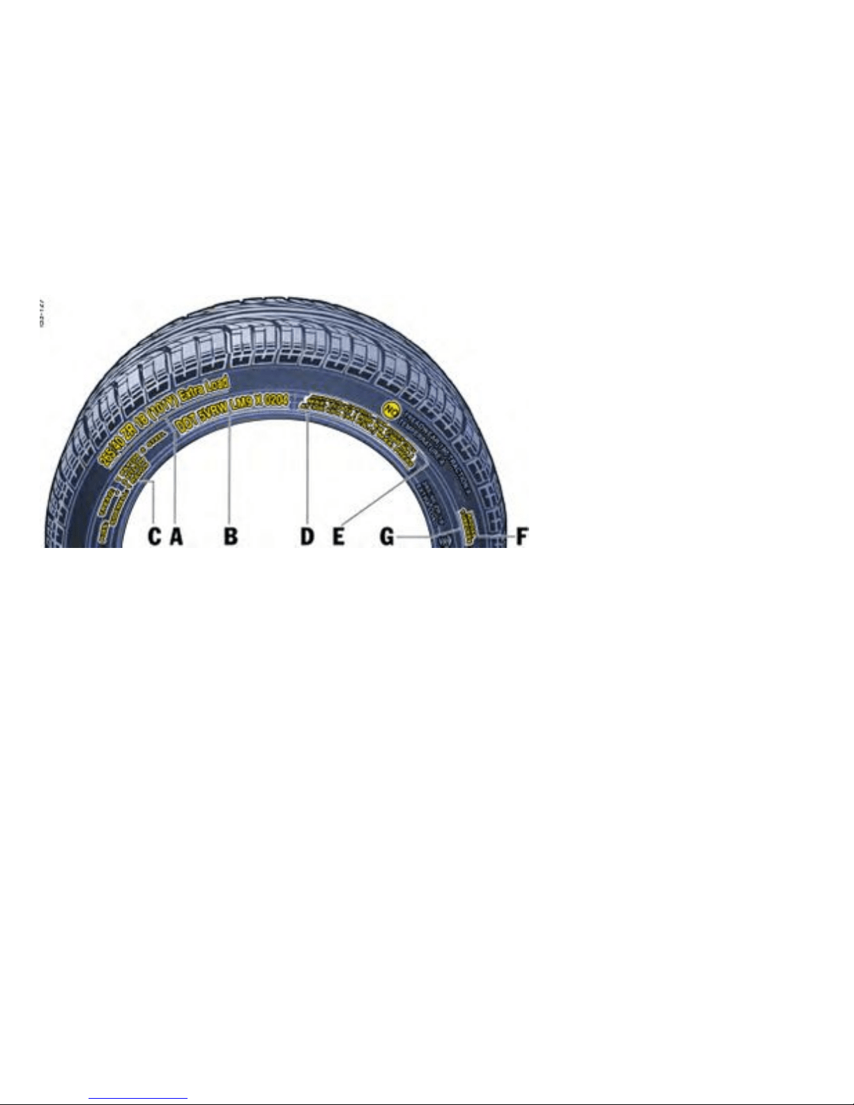
Example of Inscript ion
Inscrip tion on radial tire
A Tire size
Examp le: P 265/40 ZR 18 101 Y
– P - The tire is designed for Passenger vehicle.
This information is not included on all tires.
– 265 - Indication of tire width in mm
– 40- Indication of tire height to tire width ratio in
percent
– ZR-code letter for radial tires for speed s
above 150 mph / 240 km/h. Th ere are cur-
rently no standards concerning tire strength at
speeds above 150 mph (240 km/h).
– R- Belt type code letter for radial
– 18 - Indication of rim diameter in inches
– 101 - Load capacity coefficient
– Y - Speed code letter
– XL (Extra Load)- Tire with increased load
rating
B TIN (Ti re Identication Number)
Example: DOT xx xx xxxx xxxx
– DOT The DOT symbol indicates that the tires
comply with the requirements of the US
Department of Transportation and provides
informa tion about:
– first two-digi t code means manufacture’s
identification mark.
– second two-digit code means tire size.
– third four-digit code means tire typ e code.
246Practical Tips, Emergency Service
Downloaded from www.ManualsFile.com manuals search engine
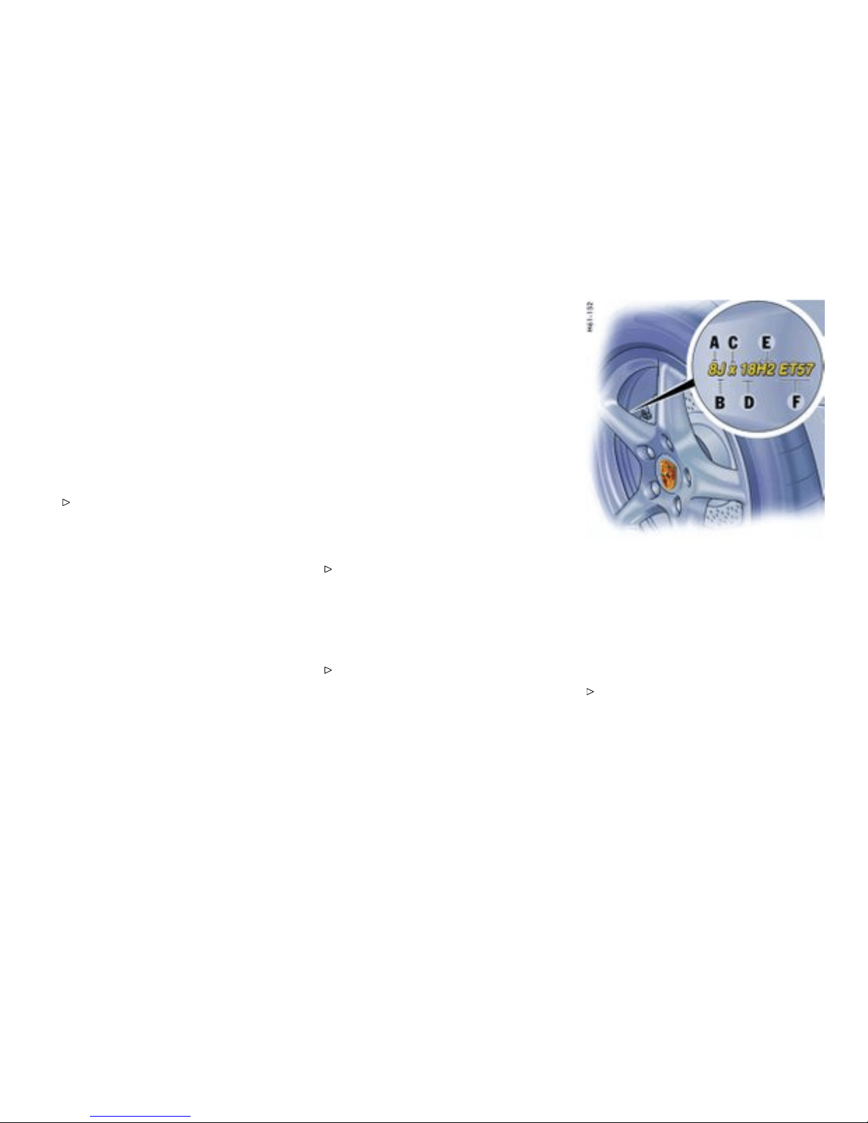
– fourth four-digit code means date of manu-
facture. If, for example, the last four numbers
read 0204, the tire was produced in th e 2nd
week of 2004.
C Tire ply composition and material
The number of layers in the tread and sidewalls and
their material comp osition.
D Maximu m permissible ination pressure
The maximum perm issible cold inflation pressure
to which a tire can be inflated.
Do not exceed the permissible inflation
pressure.
E Maximum Load rating
The maximum load in kilograms and pounds can be
carried by the tire. If you replace tires always use a
tire that has th e same maximum load rating as the
factory installe d tire.
F Radial
The identification indicates if the tire has radial
structure.
G Term of tubeless or tube tire
Identif ication for tubeless tires.
Speed code letter
The speed code letter indicate s the maximum
permissible speed for the tire. This cod e letter is
shown on the tire sidewall.
T = u p to 118 mph (190 km/h)
H = up to 131 mph (210 km/h)
V = up to 150 mph (240 km/h)
W = u p to 167 mph (270 km/h)
Y = up to 186 mph (300 km/h)
Tip on driving
Tires with a maximum speed rating that is lower
than the specified maximum vehicle speed may be
mounted only if they bear an M+S identification on
the tire sidewall.
Please note that in addition to the wi nter tires,
all-season and all-terrain tires are also subject
to speed limits and bear this identification.
Inscrip tion on light alloy wheel s
Mainte nance note
Protect the valve insert s against soiling with
valve caps. Use only plastic valve caps. Soiled
valve inserts can cause a gradual loss of a ir.
A - Rim width in inches
B - Rim-ange contour code letter
C - Symbol for drop-center rim
D - Rim diameter i n inches
E - Double hump
F - Rim offset in mm
Note on operation
The rim width in inches A and the rim o ffset F
are v isible from th e outside. This information
can be found near the tire valve.
Practical Tips, Emergency Service
247
Downloaded from www.ManualsFile.com manuals search engine

Loading Information
Denitions
The Curb weight - actual weight of your vehicle
- vehicle weight including standard and optional
equipment, fluids and emergency tools. T h is
weight does not include passengers and cargo.
The Gross Vehicle Weight is sum of the curb
weight and the weight of passengers and cargo
combine d.
The Gross Vehicle Weight Rating is the maxi-
mum total weight of vehicle, passengers, luggage
and optional equipment.
The Gross Axle Weight Rating is the maxim um
load limit for the front or the rear axle . This
information is located on the safety compliance
sticker located in the driver’s side door jamb.
For determining t he compatibilit y of the tire and
vehicle load capabi lities:
Please obse rve the chapter ”TIRES, RIMS,
TRACK S” on page 298.
The load capacity coefficient (e.g. “101”) is a
minimum requirement.
The Gross Combined Weight Rating is the maxi-
mum total weight rating of vehicle, passengers and
cargo.
The Vehicle Capacity Weigh t - Load Limit - is the
maximum total weight limit specified of the load
(passengers and cargo) for the vehi cle. This is the
maximum weight of passeng ers and cargo that can
be loaded into the vehicle. This information can be
found on the tire pressure plate.
The maximum loaded vehicle weight is the sum
of curb weight, accessory weight, vehicle capacity
weight and production options weight.
The load rating is the maximum load that a tire is
rated to carry for a given inflation pressure.
The maxim um load rating is the load rating for a
tire at the maximum permissble inflation pressure.
The cargo capacity is the permissible weight of
cargo, the subtracted weight of passenger s from
the load limit.
Never exceed the permissible limits.
Danger!
Risk of loss of control, damage to vehicle and
serio us personal injury or death.
Never exceed the specified axle loads.
Overloading can shorten the service life of
the tires and car, as well as lead to dangerous
vehicle reactions and long braking distances.
Damage due to overloading is not covered by
the vehicle warranty.
Example for determining the combined weight of
occupants and cargo
Vehicle Load Capacity
The combined weight of occupants and cargo
should never exceed the w eight shown on the
tire plate in the vehicle.
Please observe the chapter ”TIRE PRESSURE
PLATE” on page 240.
Never exceed the numbe r of passengers
shown on the tire pressure plate in the vehicle .
248Practical Tips, Emergency Service
Downloaded from www.ManualsFile.com manuals search engine

Determining the co mbined wei ght of occupants
and cargo :
Add the weight of all occupants and then add
the total luggage weight (gure).
Steps for determining correct load limit
1. Locate the stateme nt " The combined weight of
occupants and cargo should never exceed XXX
pounds" on your vehicle’s placard (depending
on the date of manufacture).
2. Determin e the combined weight of the driver
and passenger that will be riding in your
vehicle.
3. Subtract the combin ed weight of the driver and
passenger from XXX kilograms or XXX pounds.
4. The resulting figure equals the available
amount of cargo and luggage load capacity.
For example, if the "XXX" amount equals 400
lbs. and there will be two - 150 lb passengers
in your vehicle, the amount of available cargo
and luggage load capacity is 100 lbs. (400 -
300 (2 x 150) = 100 lbs.).
5. Determine the combined weigh t of luggage
and cargo being loaded on the vehicle. That
weight may not safely exceed the available
cargo and luggage load capacity calcul ated in
Step 4.
Practical Tips, Emergency Service
249
Downloaded from www.ManualsFile.com manuals search engine
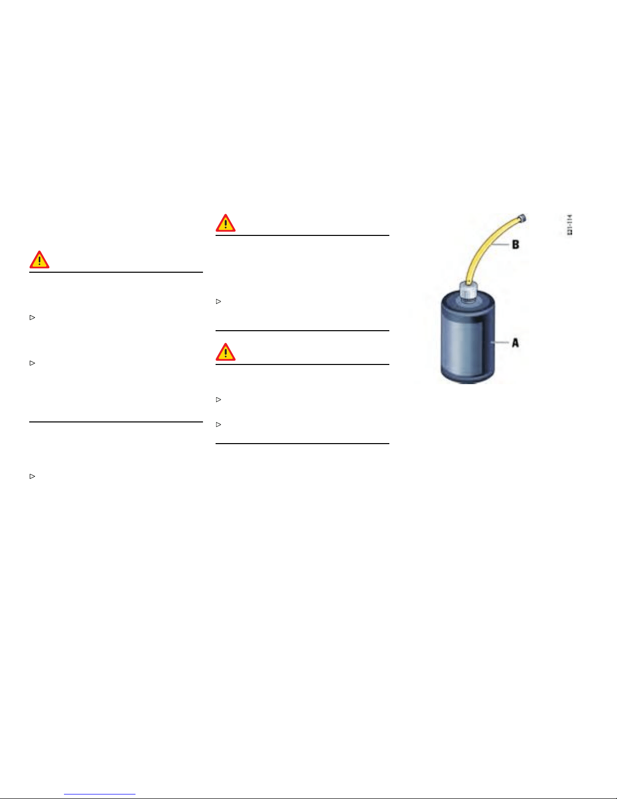
Flat Tire
Gener al information
Warning!
Failure to follow these instructions may result
in serious persona l injur y or death to you or to
bystanders.
If you have a flat tire, move a s afe distance
off the road. Turn the emergency flasher on
and use other warning devices to alert other
motorists. Set the parking brake.
Do not park your vehicle where it may contact
dry grass, brush or other flammable materi als.
The hot parts of the exhaust system could set
such materials on fire, thereby causing both
property damage and serious personal injury
or death.
A tire sealant and compressor with pressure
tester are located in the toolbox in the luggage
compartment.
Please observe the sa fety and operating
instructi ons on the special sealant bottle with
a special Porsche part number and on the
compressor - these are essential.
Caution!
Sealing the tire wit h the tire repair kit is only
an emergency repair. Even with the tire
air-tight, it may be used only for shor t trips
in an emergency. The maximum per mitted
speed is 50 mph (80 km/h).
Do not use commercially available sealant or
tire inflating bottle s. Use only the tire sealant
located in the luggage compartment.
Warning!
Risk of accident resulting in serious personal
injury or death.
Have tires replaced by a specialist workshop
as soon as possible.
Avoid hard acceleration and high cornering
speeds.
A - Filler bottle
B - Filler hose
Tire sealant
Usage
The tire sealant can be used to seal small cuts,
especia lly in the tire tread.
Sealing the tire wit h the tire sealant is only an
emergency repair, so you can drive to the next
workshop. Even with the tire air-tight, it may be
used only for short trips in an e mergency.
250Practical Tips, Emergency Service
Downloaded from www.ManualsFile.com manuals search engine
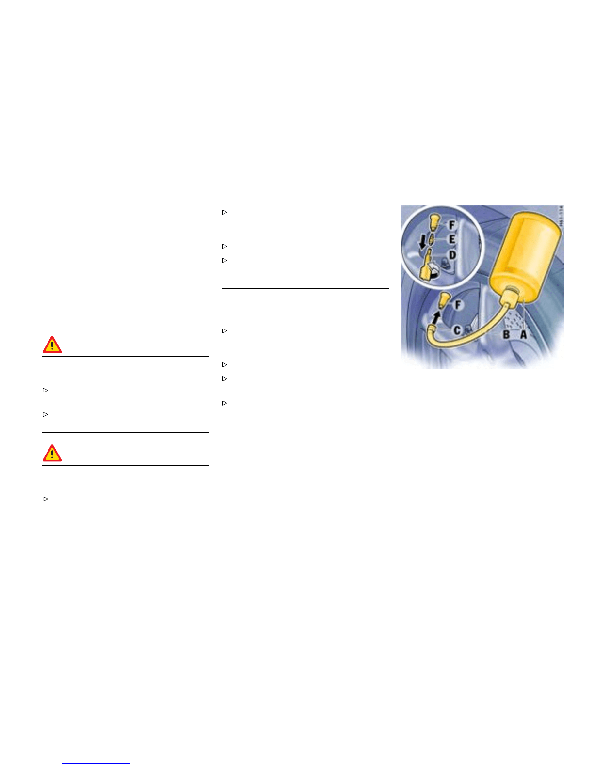
The tire sealant and a compressor with pressure
tester can be found in the tool box in the luggage
compartment.
The tire sea lant comprises :
– A filler bottle
– A filler hose
– A valve turner and
– A spare valve insert
– A sticker denoting the maximum permissible
speed for the driver’s field of vi sion.
Danger!
Risk of accident resulting in serious person a l
injury or death.
Use the tire sealant only in the case of cuts or
punctures no larger than 0.15 in. (4 mm).
Never use the tire seala nt if the rim is dam-
aged.
Warning!
The sealant is highly ammable and harmful
to health.
Fire, naked flame and smoking are prohibited
when handling tire sealant.
Avoid contact with skin, eyes and clothing
due to caustic chemical properties of the tire
sealant.
Keep tire sealant away from children.
Do not inhale vapors, due to consequent harm
to personal health resulting in serious personal
injury or death.
In case of contact with the sealant:
If sealant gets on the ski n or in the eyes,
thoroughly rinse the affected part of the body
off immediately.
Change soiled clothing immediately.
Get medical attenti on immediately in the event
of an a llergic reaction.
If sealant was swallowed, thoroughly rinse out
the mouth without delay and drink plenty of
water. D o not induce vomiting. Get medical
attention immediately.
A - Filler bottle
B - Filler hose
C - Plug of the ller hose
D - Valve turner
E - Valve insert
F - Tire valve
Inserting sealant
1. Leave the object that caused the puncture in
the tire.
2. Remove sealant and the enclosed sticker from
the luggage compartment.
3. Adhere the sticker in the driver’s field of vision.
4. Shake filler bottle A.
Practical Tips, Emergency Service
251
Downloaded from www.ManualsFile.com manuals search engine
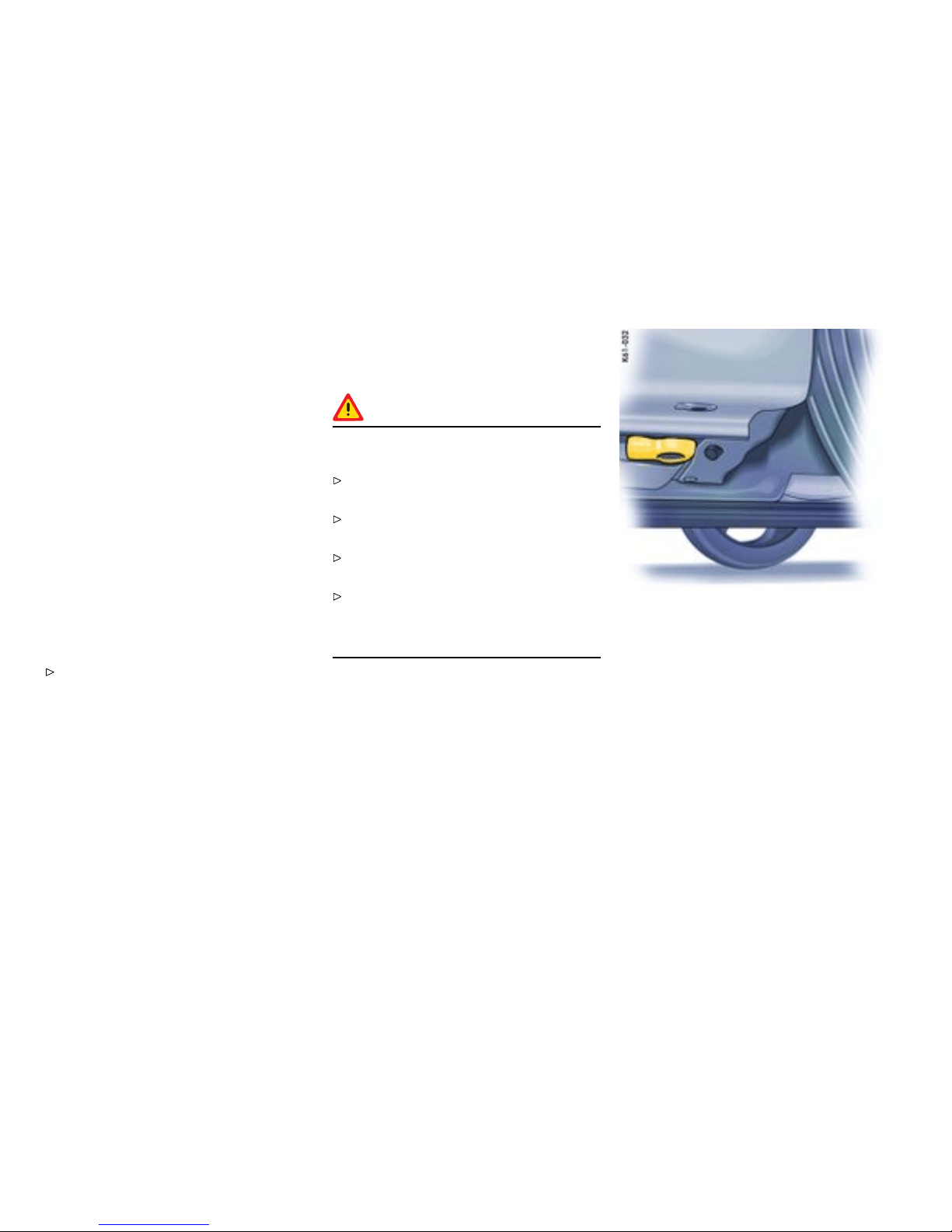
5. Screw filler hose B onto the filler bottle. The
filler bottle is now open.
6. Unscrew valve cap from tire valve F.
7. Remove valve insert E f rom the tire valve with
valve turner D. Keep the valve insert in a clean
and dry place.
8. Remove plug C of the filler hose B.
9. Push filler hose onto the tire valve.
10. Hold filler bottle higher than the level of the tire
valve and press it together forcefully until the
bottle is completel y emptied into the tire.
11. Pu ll filler h ose off the tire valve.
12. Twist the valve i nsert firmly into the tire valve
using the valve turner.
13. Connect the compressor to the cigarette
lighter and inflate the tire to the prescribed tire
pressure.
Please observe the chapter ”TIRE PRESSU RE
FOR COLD TIRES” on page 299.
14. Screw val ve cap onto the tire valve.
15. Ch eck the tire pressure after driving for
around 10 m inutes. If the tire pressure is
less than 22 psi (1.5 bar), do not c ontinue
driving. If a value of more than 22 psi (1.5 bar)
is indicated, correct the pressure to the
prescribed value.
16. Pl ease consult your authorized Porsche
dealer.
Care Instructions
After drying, any sealant that emerges can be
peeled off like a film.
Warning!
Risk of accident resulting in serious personal
injury or death.
Have the tire replaced by an authorized
Porsche dealer immediately.
Avoid hard acceleration and high cornering
speeds.
Do not exceed maximum speed of 50 mph
(80 km/h).
Please always observe the safety and oper-
ating instructi ons, which can be found in the
separate operating inst ructions for the sealant
and on the compressor.
Front jacking point
Lifting the vehicle
Lifting the vehicle wi th a lifting platform or
garage lift
The car must be raised only at the illustrated
jacking points.
252Practical Tips, Emergency Service
Downloaded from www.ManualsFile.com manuals search engine
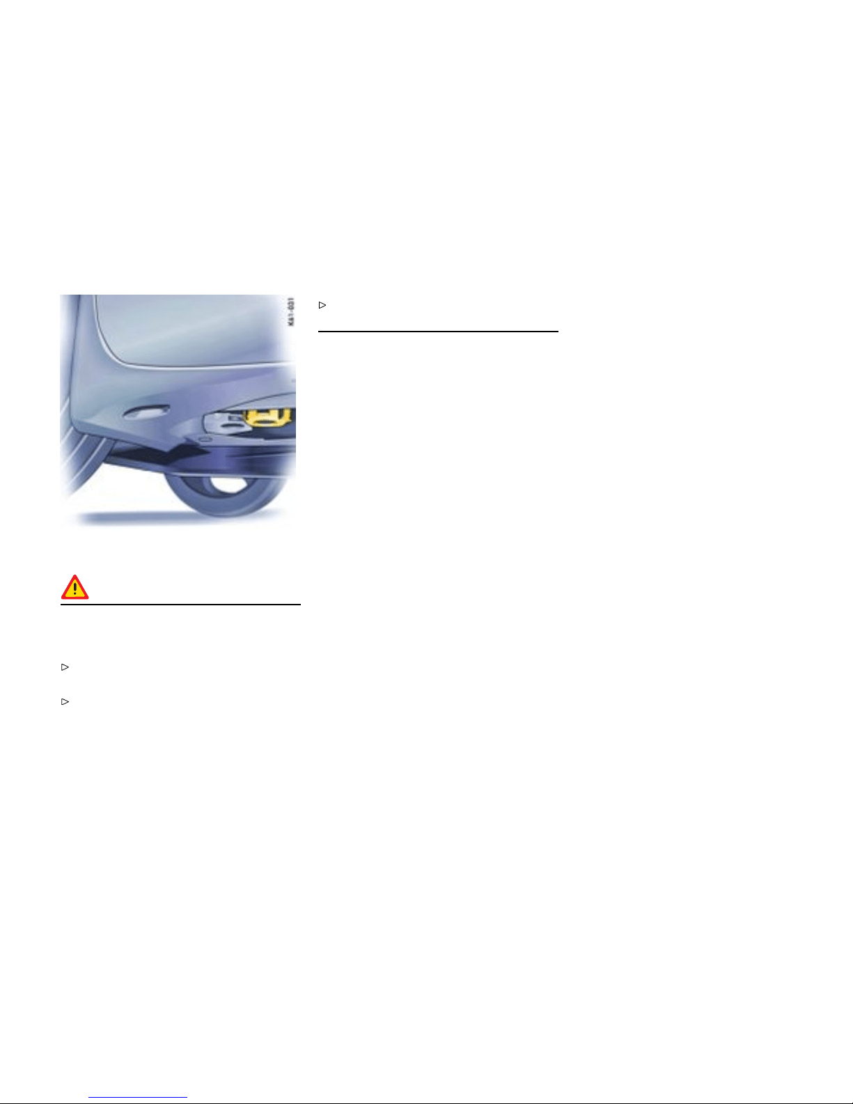
Rear jacking point
Danger!
Serious personal injury or death and/or
serious damage to the engine or the vehicle
may occur, if you lift the vehicle improperly.
Never lift the vehicle at any other place than
the jacking points.
Never lift the vehicle by the engine, transmis-
sion or axles.
Do not damage any sensitive compo n ents in
the vicinity of the jacking points.
Platform lift
Before the car is driven on to a lifting platform ,
it must be ensured that there is enough space
between the lifting platform and the vehicle.
Garage lift
A garage lift may be used only at the ill ustrated
jacking points.
Practical Tips, Emergency Service
253
Downloaded from www.ManualsFile.com manuals search engine
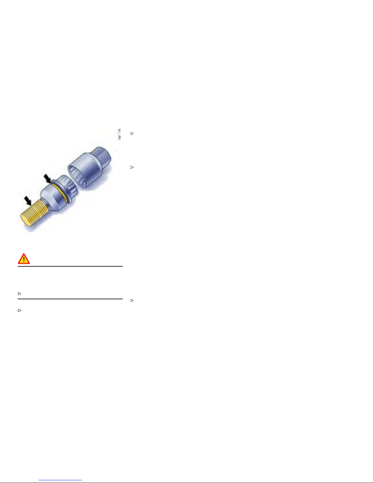
Wheel Bolts
Danger!
Risk of wheel bolt breakage and wheel
separation, resulting in serious personal
injury or death.
Follow all instructions concerning wheel bolts.
Always clean the wheel bolts before f itting.
Apply a thin coat of Optimoly TA (aluminum
paste) on the thread and between the bolt
head and movable spherical cap ring (arrows).
The bearing surface of t he spherical cap
facing the wheel mus t not be greased.
Replac e dam aged wheel bolts. Only use
the Original Porsche wheel bolts specially
designed for this vehicle type.
Tightening torque
Tightening torque of wheel bolts:
130 Nm/96 ftlb.
Wheel Securing Bolts
If the wheels have to be removed at the workshop,
please do not forget to hand over the wrench
socket for the wheel securing bolts along with
the car key.
The wrench socket for the wheel securing bolts is
in the tool box.
To loosen or tighten the wheel bolt with anti-theft
protection, a wrench socket with the appropriate
coding must be used between the wheel bolt and
the wheel-bolt spanner.
When positio ning the wrench socket , ensure
that it engages fully in the teeth of the wheel
bolt.
254Practical Tips, Emergency Service
Downloaded from www.ManualsFile.com manuals search engine
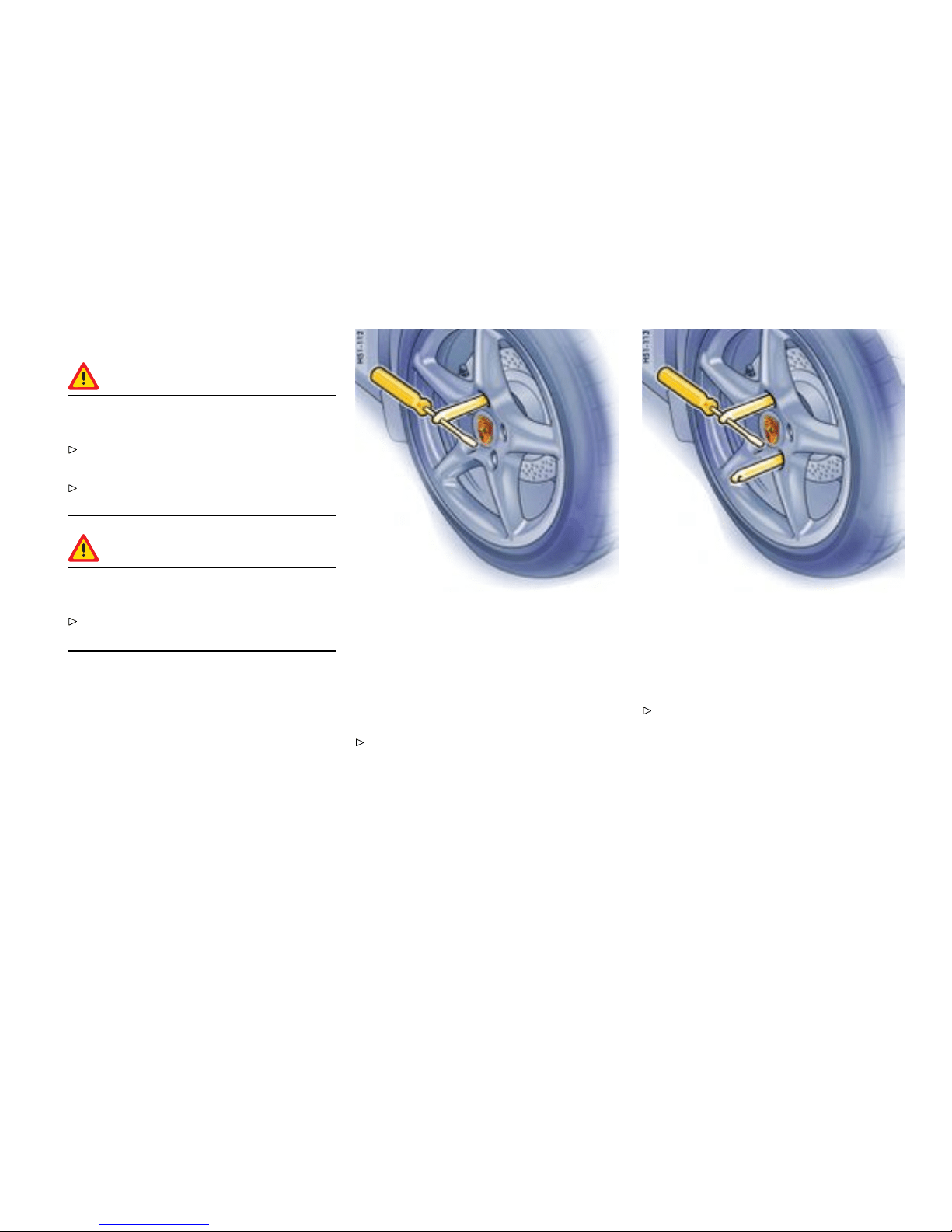
Changing a wheel
Danger!
Risk of serious personal injury or death. The
car may slip off the jack.
Make sure t h at no one is in the vehicle when
jacking up and changing a wheel.
Always place the car on stable supports if work
has to be carried out under the car.
Warning!
Risk of damage to the brake discs of the
Porsche Ceramic Composite Brake (PCCB).
Always screw in both assembly aids when
changing a wheel.
Note
The tools required for changing a wheel (e.g. jack,
wheel bolt wrench, assembly aids) are no t suppl ied
with the car. They are available at your authorized
Porsche dealer.
1. Fully apply the handbrake, engage 1st gear or
select position P and withdraw the ignition key.
2. Secure the car against rolling away, e.g. by
means of wedges under the wheels on the
opposite side. This is particularly important on
slopes.
Screw in ass embly aid for vehicles without
Porsche Ceramic Composite Brake
3. Slightly slack en the wheel bolts of the wheel to
be changed.
4. Raise the car until t he wheel lifts off the
ground.
Please observe the chapter ”LIFTING THE
VEHICLE” on page 252.
Screw in two assembly aids for vehicles with
Porsche Ceramic Composite Brake
Note on operation
To remove or mount the spacers:
Please observe the chapter ”SPACERS” on
page 257.
5. Remove 1 or 2 wheel bolts (see respe ctive
illustra tion). Screw in assembly aids instead of
the wheel bolts. Remove the remaining wheel
bolts.
6. Take the wheel off and put a new wheel on.
Practi cal Tips, Emergency Service
255
Downloaded from www.ManualsFile.com manuals search engine

7. Screw in wheel bolts; remove assembly aids
and screw in the remaining wheel bolts. Initially
tighten bolts in diagonally opposite sequence
so that the wheel is centered.
Please obse rve the chapter ”WHEEL BOLTS”
on page 254.
8. Lower the car completely.
9. Tighten wheel bolts in diagonally opposite
sequenc e.
Immediately after changing a wheel, use
a torque wrench to check the prescribed
tightening torque (130 Nm/96 ftlb.).
Checking tire pre ssure with a pressure
gauge
Please observe the chapter ”TPC TIRE
PRESSURE MONITORING” on page 122.
1. Remove the valve stem cap from the tire.
2. Press t he pressure gauge onto the valve stem.
Note on operation
Do not press too hard or force the valve stem
sideways, or air will escape. If the sound of ai r
escaping from the tire is heard, reposition the
pressure ga uge.
3. Read the tire pressure on the gauge stem and
compare it to the permissible tire pressure.
This information can be found on the t ire
pressure plate or in the chapter Technical
Data.
Please obser ve the chapter ”TIRE PRESSURE
FOR COLD TIRES ” on page 299.
4. Remove the pressure gauge.
256Practical Tips, Emergency Service
Downloaded from www.ManualsFile.com manuals search engine

Spacers
Gener al information to the use of spacers
Use the spacers only together with wheels
and fastening parts approved by Porsche.
Before having spacers fitted, find out about the
current authorizatio n status.
Mounting an emergency spare whee l
If 5 mm spacers are fitted, these must not be
removed to mount an emergency spare wheel.
Fitting snow chains
The use of snow chains is not permitted when
5 mm spacers are mounted.
Caution!
Risk of damage to wheel housings if the 5 mm
spacers are not removed before tting snow
chains .
In order to enabl e the fitting of snow chains,
have the 5 mm spacers removed on all 4
wheels.
Note on operation
To fit/remove the spacers: Please consult an
authorized Porsche dealer.
Removing/mounting the spacers
Required scope of p arts if the spacers are
removed
Short countersunk screws (M 6x12) Part No:
900.269.047.09
1 set of short wheel bolts Part No:
996.361.203.02
Short anti-theft protection devices Part No:
996.361.057.01
Practical Tips, Emergency Service
257
Downloaded from www.ManualsFile.com manuals search engine
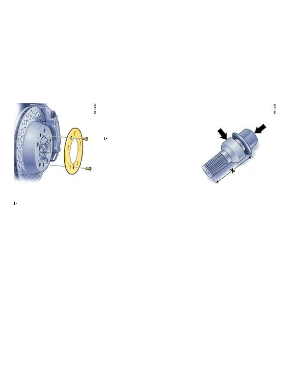
Removing the spacers
Please observe the chapter ”CHANGING A
WHEEL” on page 255.
1. Unscrew both countersunk screws (M6x16) on
the wheel hub.
2. Remove the spacer.
3. Fasten the brake disc with the short
M6x12 countersunk screws, part No.
900.269.047.09 . Tightening torque
10 Nm (7.5 ftlb.).
4. For wheel mounting withou t a spacer,
5 mm shorter whe el bolts (part No:
996.3 61.203.02) must be used. Tighten-
ing torque 130 Nm (96 ftlb.).
Mounting the spacers
Please observe the c hapter ”CHANGING A
WHEE L” on pa ge 255.
1. Remove wheel
2. Unscrew both countersunk screws (M6x12) on
the break disc.
3. Fasten the spacer with the long M6x16
countersunk screws. Tightening torque
10 Nm (7.5 ftlb.).
4. Fit wheel. To do this use the longer wheel
bolts for fastening the wheels. Tightening
torque 130 Nm (96 ftlb.).
Long wheel bolt, X - bolt length approx. 50 mm,
Arrows - marks
Wheel bolt identifyi ng features
The long wheel bolts are ident ified on the face
surface of the bolt head with GT or in red, or the
moveable spherical cap ring is galvanised in red.
The long wheel bolts must only be used together
with 5 mm spacers fitted.
The short wheel bolts are not marked in color. The
short wheel bolts must only be us ed without 5 mm
spacers fitted.
Tighteni ng torque for both wheel bolts:
130 Nm (96 ftlb.).
258Practical Tips, Emergency Service
Downloaded from www.ManualsFile.com manuals search engine
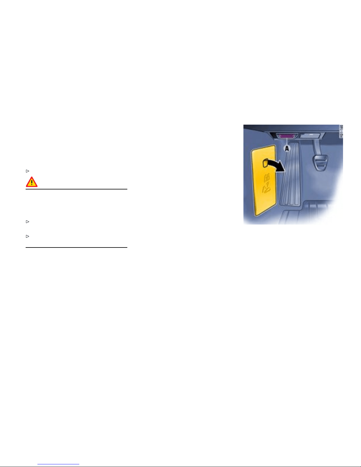
Electrical System
Gener al information
In order to avoid dama ge and f a ults in e lectrical or
electronic systems, elect rical accessories should
be installed at your authorized Porsche dealer.
Only use accessories authorized by Porsche.
Danger!
Risk of short circuit and re, resulting in
serious personal injury or death. Replacing
fuses or relays with the engine running or the
ignition on could cause electrical shock.
Disconnected the battery during all work on
the electrical system.
Please observe the c hapter ”BATTERY” on
page 262.
Relays
Defective relays should be changed only by an
authorized workshop.
Alarm sy stem, central lockin g
The status of the central locking and alarm syste m
is not c hanged by disconnecting the battery. When
the battery is disconnected, the alarm system
ceases to function.
Overlo ad protection
If the central locking system is operated more
than ten times within a minute, further operation is
blocked for 30 seconds.
Load switch-off af ter 2 hours or 7 days
If the ignition key is removed, loads which are
switched on or are in sta ndby mode (such as the
luggage compartment light, interior light and
radio) are automatically switched off after approx.
2 hours.
If the vehicle is not started or unlocked with the
remote control within 7 days, the remote control
standby function is switched off (to save the vehicle
battery ).
1. In this case, unlock the driver’s door with the
key at the door lock. L eave the door closed in
order to prevent the alarm system from b eing
triggered.
2. Press button 1 on the remote control.
The remote control is now activated again.
A - Diagnostic socket
Replacing fuses
In order to prevent damage to the electrical system
due to short circuits and overloads, the individual
circuits are protected by fuses. The fuse box is
located in the driver’s footwell.
Practical Tips, Emergency Service
259
Downloaded from www.ManualsFile.com manuals search engine
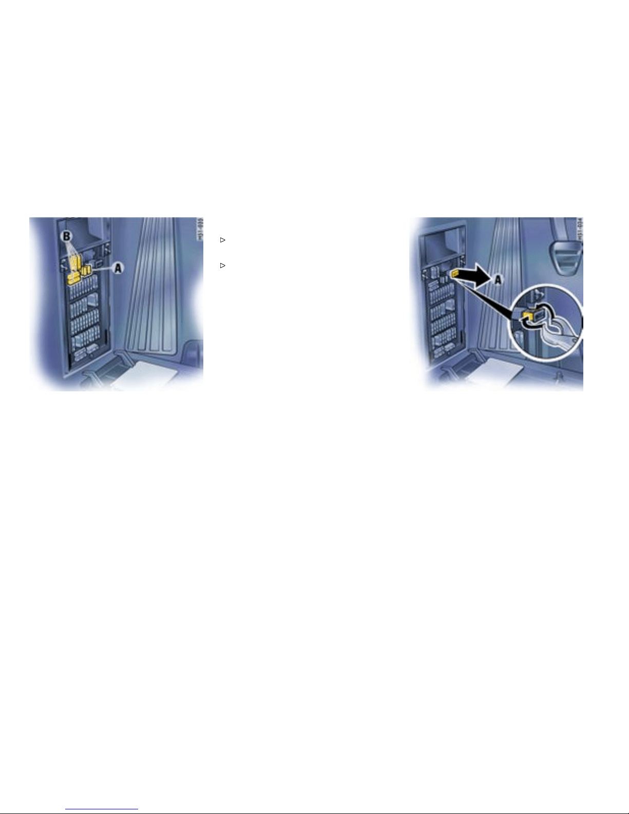
A - Plastic gripper
B - Spare fuses
1. Switch off the load with the d efective fuse.
2. Pull off plastic cover at the finger hole (arrow).
The fuse plan and instruction s for emer-
gency unlocking of the luggage compart-
ment lid can be found on t he inner side of the
cover.
3. Remove the corresponding fuse from its slot
using the plastic gripper A in order to check it.
A blown fuse can be iden tified by the melted
metal strip.
4. Replace only with fuses of the same ratin g.
Note
If a fuse blows repeat edly consult an author-
ized Porsche deal er.
Never try to “repair” fuses : you may cause
serious damage to other parts of the electrical
system.
Emerg ency unlocking of the front luggag e
compartment lid
If the battery is discharged, the lid can be opened
only with the aid of a donor battery.
Unlocking lid
1. Use the key to unl ock the vehicle at the d oor
lock.
2. Remove plastic cover over t he fuse box.
3. Pull out positive terminal A in the fus e box.
4. Use a jumper cable to connect the positive
terminal of the donor battery with positive
terminal A in the fuse box.
Note
If the vehicle was locked, the alarm horn will sound
when the negative cable is connected.
5. Use the second jumper cable to connect the
negative terminal of the donor battery with
latch striker B.
6. Unlock the front lu ggage compartment lid
with the remote control. The alarm system is
switched off.
260Practical Tips, Emergency Service
Downloaded from www.ManualsFile.com manuals search engine
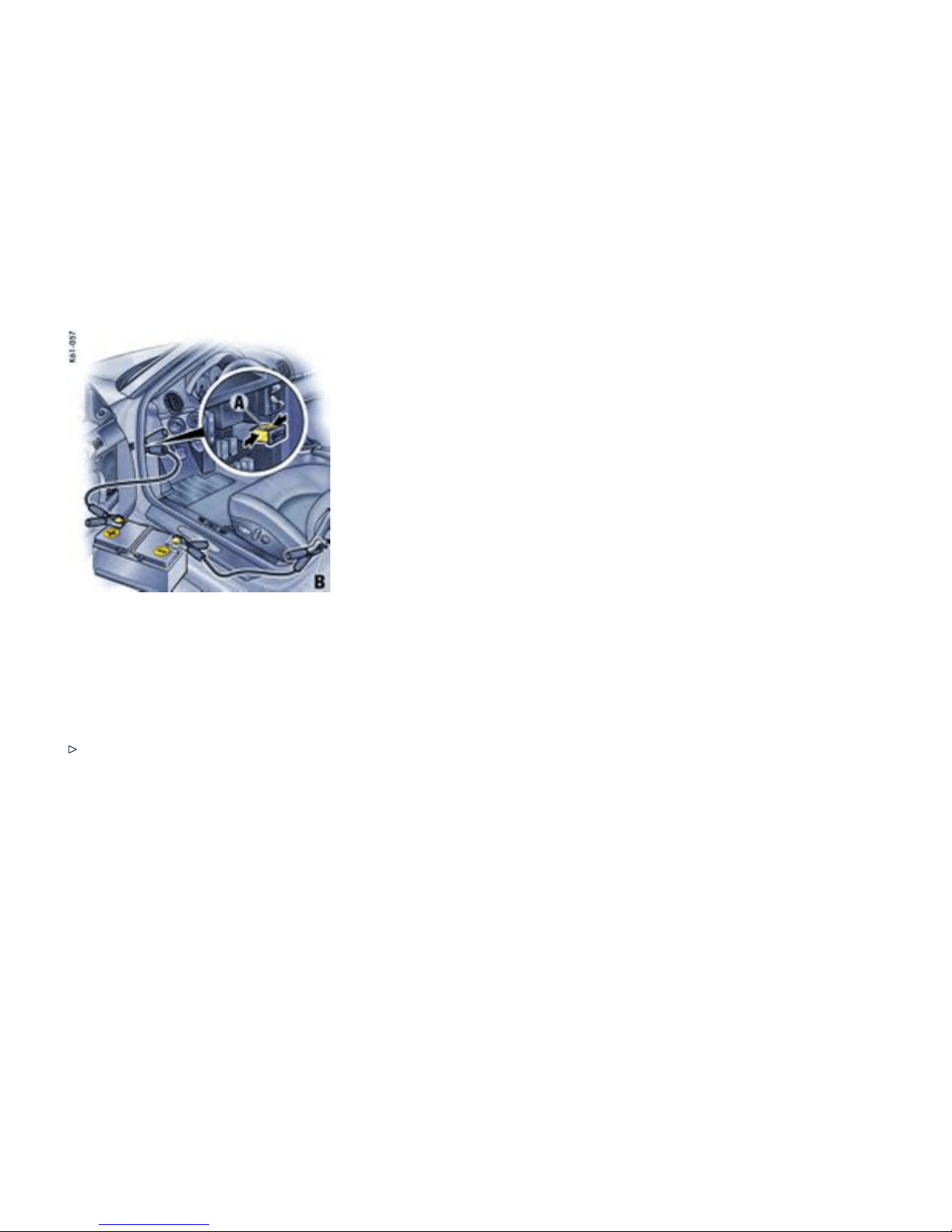
7. Disconnect the negative cable first, then the
positive cable .
8. Push the positive terminal A into the fuse box
and push on the plastic fuse box cover.
Note
The engine cannot be started with t his method.
Please observe the chapter ”EMERGENCY
STARTIN G WITH JUMPER CABLES” on page
267.
Practical Tips, Emergency Service
261
Downloaded from www.ManualsFile.com manuals search engine
Battery
Danger!
Risk of short circuit and re, resulting in
serious personal injury or death.
Observe all warning notes on the battery.
Disconnect the battery during all work on the
electrical system.
Do not lay tools or other metal objects on the
battery as they could cause a s hort circuit
across the battery terminal.
Danger!
Hydrogen gas generated by the battery
could cause an explosion, result ing in serious
personal injury or death.
Do not expose the battery to an open flam e,
electric a l spark or a lit c i g arette.
Do not wipe battery with a dry clot h.
Danger!
Risk of serious personal injury or death and
damage to the fabric, metal or paint.
Wear eye p rotection.
Do not allow battery acid to c ome in contact
with your skin, eyes, fabric or painted surfac -
es.
If you get electrolyte, which is an acid, in your
eyes or on your skin, immediately rinse with
cold water for several minutes and call a
doctor.
Spilled electrolyte must be rinsed off at once
with a solution of baking soda and water to
neutral ize the acid.
Warning!
Batter y posts, terminals and related acces-
sories contain lead and lead compounds,
chemicals known to the State of California to
cause cancer and reproductive harm.
Always protect your skin by washing thorough-
ly with soap and water.
Danger!
Risk of explosion as a result of static charge,
resulting in serious personal injury or death.
Do not wipe the b attery with a d ry c loth.
Eliminate potential electrostatic charge by
touching the vehicle before touching the
battery.
262Practical Tips, Emergency Service
Downloaded from www.ManualsFile.com manuals search engine

Charge st ate
A well charged battery will not only prevent starting
problems but will also last longer.
In order to avoid un intended battery dischar ge
Switch off unnecessary electrical lo ads in city
traffic, on shor t trips or in a line or traffic.
Always remove the ignition key from the
ignitio n switch when leaving the car.
Avoid frequent operation of the Porsche
Communication Management system when
the engine is not running.
Battery care
Ensure that b attery is securely mounted.
Keep terminal s and connections clean
and properly tightened. Corrosion can be
prevented by coating the terminals and
connections with petroleum jelly or silicone
spray.
Ensure that vent caps are securely tightened
to prevent spillage.
Checking the electrolyte uid level
Generally, the electrolyte level must be checked
more often in summer than in winter, and more
often when driving long distances.
When adding water, use only clean containers.
In no case may alcohol (e.g. window cleaner
residues) be permitted to enter the battery.
Unscrew and open the filler vent caps of each
cell.
With the car on a leve l surface, the fluid level should
meet the indicator mark in each cell.
If necessary, top up with distilled water.
Do not use acid. Only fill up to the mark,
otherwise the el ectrolyte will overflow when
the battery is being charged and cause
damage.
Battery c harging
Autom otive batteries loose their efficie ncy when
not in use. The charge available in your battery
can be measured with a battery hydrometer. We
recommend that the battery voltage be tested
by your Porsche dealer who has the appropriate
equipment.
If the car is not driven for prolonged periods, the
battery must be charged at least every 6 weeks.
A discharged battery allows rapid formation of
sulfates, leading to permature deterioration of the
plates.
Danger!
Hydrogen gas generated by the battery
could cause an explosion, resulting in serious
person a l injury or death.
Charge battery in a well ventilated area.
Never charge a frozen battery. It may explode
because of gas trapped in the ice. Allow a
frozen battery to thaw out first.
If you get electrolyte, which is an acid, in your
eyes or on your skin, immediately rinse with
cold water for several minutes and call a
doctor.
Practical Tips, Emergency Service 263
Downloaded from www.ManualsFile.com manuals search engine

Slow battery charging
1. Pay attention to all warnings and follow
instructions that come with your battery
charger.
2. When charging, ensure adequate ventilation.
3. Remove battery.
Please observe the chapter ”REMOVING THE
BATTERY” on page 265.
4. All vent caps should be open. The fluid level
should meet the indicator mark in each cell.
5. Ensure that charger is switched off - danger of
short circuit!
6. Connect charger ca bles. Charger cables
must be connected POSI TIV (+) to POSITIV
(+) and NEGATIVE (-) to N EGATIVE (-).
7. Switch on charger. Normally a battery should
be charged at no m ore than 10 percent of its
rated capacity. Rated capacity of the battery in
your vehicle is listed on the battery housing.
8. After charging, turn off charger and disconnect
charger cables.
9. Tighten the vent caps and reinstall battery.
Please obse rve the chapter ”INSTALLING THE
BATTERY” on page 265.
Winter o peration
The capacity and ability of the battery to store
power decreases at low o utside temperatures.
Additionally, more pow er is consumed while
starting, and the headlights, heat er, rear window
defogger, etc., are use d more frequently.
Let your Porsche dealer test the battery’s
capacity before win ter sets in.
The battery will discharge more quickly if your
vehicle is not driven on a daily basis over a distance
of several miles. The more ofte n you drive your
vehicle, and the longer the distance driven each
trip, the more opportunity the vehicle’s charging
system will have to recharge the battery.
Replacing the battery
The service life of the battery is subject to normal
wear; it depends greatly on care, climatic condi-
tions and driving conditi ons (distances, loads).
Only use an original Porsche battery with the
correct part number, as a replacement.
Please observe the disposal instructions for
batteries.
Puttin g vehicle int o operation
After the battery is connected or after a com-
pletely discharged battery is charged, the mul-
tifunctional PSM light lights up on the instrum ent
panel and a message appears on the on-board
computer to indicate a fault.
This fault can be remedie d with a few simple steps:
1. Start the engine.
2. With the vehicle stationary, perform a few
steering movements to the left and right and
then drive a short distance in a straight line
until the multifunctinal PSM light goes out
and the message on the on-board computer
disappears.
3. If the warnings do not disappear, then: Drive
carefully to the nearest authorized Porsche
dealer. Have the fault remed ied.
4. After the warnings disappear: Stop the vehicle
in a s uitable place.
5. Per f orm adaption of the power windows:
Please obser ve the chapter ”STORING END
POSITION OF THE WINDOWS” on page 35.
Ignition key/ignition lock
Do not insert the ignition key into the ignition
lock if the vehicle battery is discharged. The
ignition key can no longer be removed .
The key cannot be remove d until the vehicle
electrical system is supplied with power again.
Please observe the chapter ”EMERGENCY
UNLOCKING OF THE FRONT LUGGAGE
COMPARTMENT LID” on page 260.
Please observe the chapter ”EMERGENCY
STARTING WITH JUMPER CABLES” on page
267.
264Practical Tips, Emergency Service
Downloaded from www.ManualsFile.com manuals search engine
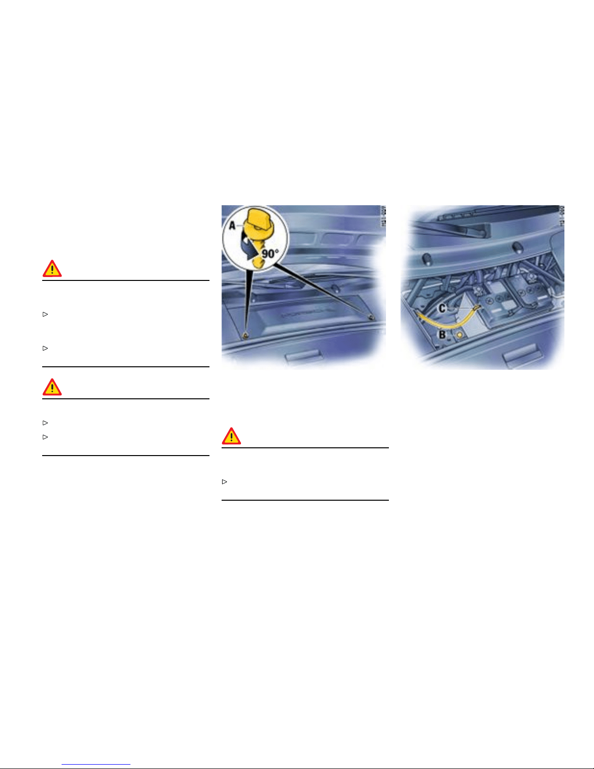
Remov ing the battery
The required tool is in the tool kit.
The battery is located in the front luggage compart-
ment under a black plastic lid.
Warning!
Risk of damage to alternator and electronic
control units.
Do not disconnect battery while the engine is
running. This also applies to cars equipped
with a battery main switch.
Never drive the car with a disconnected
battery.
Warning!
Risk of caustic burns from e scaping acid.
Keep vent caps on to avoid spillage.
Do not tilt the battery when removing and
installin g it.
1. Switch off engine and all electrical loads.
2. Open turn-locks A. Re move plastic lid.
3. Pull off vent hose C.
Danger !
Risk of short circuit and explosion, resulting in
serious personal injury or death.
Important: disconnect the negative (-) ground
wire first, and then the positive (+) cable.
4. Important: disconnect the negative (-) ground
wire first, and then the positive (+) cable -
danger of short circuit!
5. Unscrew fastening screw B.
6. Remove battery.
Installing the batt ery
1. Put battery in and push it all the way to the
stop.
2. Screw in fa stening screw B.
Practical Tips, Emergency Service
265
Downloaded from www.ManualsFile.com manuals search engine
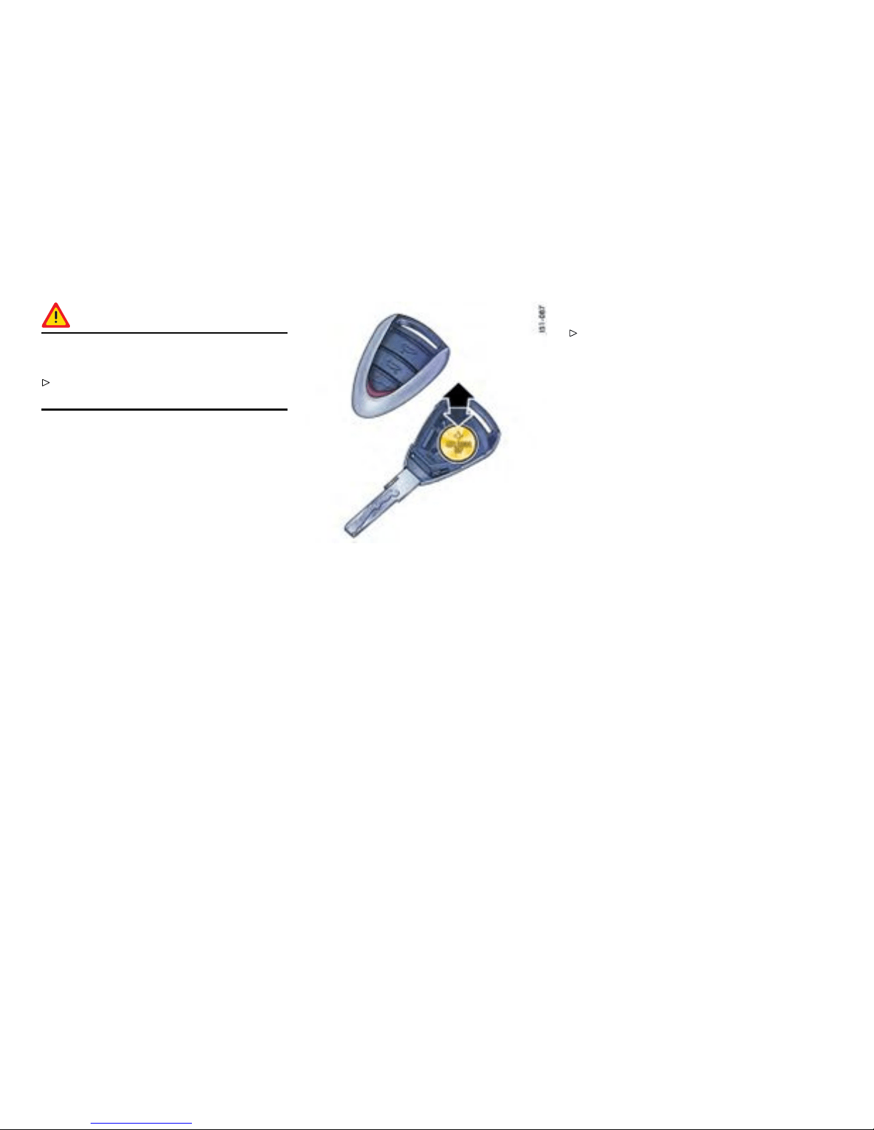
Danger!
Risk of short circuit and explosion, resu lting in
serious personal injury or death.
Important: connect the positive (+) cable first,
and then the negative (-) ground wire.
3. Important: connect the positive (+) cable first,
and then the negative (-) ground wire - risk of
short circuit!
4. Push on central vent hose C.
5. Fit plastic lid. Lock turn-loc ks A.
Replacing the remot e-control battery
The battery should be change d when the range of
the radio remote control becomes smaller or when
the light-emitting diode no l onger flashes when the
remote control is operated.
1. Using your finger nail or a small screwdriver,
carefully lift off the cover of the key grip
(arrow).
2. Replace battery (paying attention to the
polarit y). Replacement battery - Lithium CR
2032, 3 volts
3. Replace the cover and press together firmly.
Please observe the disposal instructions for
batteries.
Note
Please dispose of batteries in compliance with
any and all g overnment regulat ions.
266Practical Tips, Emergency Service
Downloaded from www.ManualsFile.com manuals search engine
Emergency Starting with Jumper
Cables
Gener al information
If the battery is discharged, e.g. in winter or after
the car has been parked for a long time, the ba ttery
of another car can be used for starting with the
help of jumper cables. Make sure the voltage of
both batteries is the same. Bo th batteries must
be 12 volt types. The capacity (Ampere hours, Ah)
of the booster battery must not be substantially
less than that of the discharged battery. The
discharged battery must be correctly connected to
the vehicle’s electrical system.
Please observe the c hapter ”BATTERY” on
page 262.
Please observe the chapter ”EMERGENCY
UNLOCKING OF THE FRONT LUGGAGE
COMPARTMENT LID” on page 260.
Note
Do not try to start the car by pushing or
towing. Damage to the catalytic converters
and other components of t he car may result.
Danger !
Risk of short circuit, damage and explosion,
resulting in serious personal injury or death.
Use only jumper cables of adequate diameter
cross-section and fitted with completely
insulated alligator clips.
Follow all warnings and instructions of the
jumper cable manufacturer.
When connecting jumper cables, make sure
that they cannot get caught in any moving
par ts in the engine compartment. The jumper
cables must be long enough so that neither
vehicles nor cables touch another.
The vehicles must not be in contact, otherwise
current might flow as soon as the pos itive
terminals are connected.
The cable clamps must not be allowed to
contact each othe r when one end of the
jumper cables are connected to a battery.
Ensure that tools or conductive jewelry (rings,
chains , watch straps) do not come into contact
with the positive jumper cable or the positive
battery post.
Improper hook-up of jumper cables can ruin
the alternator.
Warning!
Danger of caustic burns.
Do not lean over the battery.
Warning!
Danger of gas explosion.
Improper use of booster battery to start a
vehicle may cause an explosion, resulting in
seriou s personal injury or death.
Keep sources of i gnition away from the
battery, e.g. open flame, burning cigarettes or
sparking due to cable contact or welding work.
A discharged battery can freeze even at
23°F /-5°C . Before connecting jumper cables,
a frozen battery must be thawed out.
Practical Tips, Emergency Service 267
Downloaded from www.ManualsFile.com manuals search engine

Connect jumper cables in the following
sequence:
Always observe the sequence below:
1. Connect the positive lead (red) to the
positive termi nal of the discharged battery
first, then connect it to the positive terminal of
the donor battery.
2. First connect the negative cable (bla ck)
to the negative terminal of the donor battery,
then connect it to a suita ble grounding point on
the vehicle with the discharged battery. This
grounding point must lie as far as possible
from the battery. For example, a so lid metal
par t or the engine block are sui table grounding
points. If no suitable grounding points are to
be found on either vehicle, the negative cable
must carefully be connected directly to the
negative terminal of th e battery. If a suitable
grounding point is to be found only on th e
donor vehicle, the negativ e cable must f irst be
connected to th e terminal of the discharged
battery, then to the grounding point of the
donor vehicle.
3. Run the engine of the donor car at a higher
speed.
4. Start the engine. An attem pted start using
jumper cables shoul d not last more than
15 seconds. Then allow a waiting period of
at least one minute.
Note
Before disconnecti ng the jumper cables, electrical
loads such as the heated rear window and the
heating fan blower should be switched on (the
vehicle ’s lights must not be switched on). This
reduces voltage peaks which may occur when
disconn ecting the jumper cables.
5. With the engine running, remove both jump
leads in reverse order.
268Practical Tips, Emergency Service
Downloaded from www.ManualsFile.com manuals search engine
Replacing bulbs
Gener al information
Warning!
Risk of short circuit.
Always switch off the relevant componen ts
when changing bulbs.
Danger!
Risk of serious personal injury or death. The
Bi-Xeno n headlights are under high voltage
when installe d.
Exercise extreme caution when working in the
area of the Bi-Xenon headlig hts.
Warning!
Risk of damage. Bulbs of a higher wattag e
can damage the lamp housing.
Only use the bulbs specified in the bulb chart.
New bulbs must be clean and f ree from oil,
grease and fingerprints. Therefore, never
touch bulbs with your bare hands. Use a
cloth or soft paper while replacing bulbs.
Caution!
Risk of damage to headlights due to excessive
temp eratures and abrasion.
Attach no coverings (e.g. films, “stone
guards”) in t he area of the headlights.
Use soapy water only to clean light lenses
and plastic headlight lenses. In no case may
chemical cleaners or other volatile cleaning
fluids be used.
To prevent scratches, do n ot rub with a d ry or
merely moist cloth, tissue or insect sponges.
Practical Tips, Emergency Service 269
Downloaded from www.ManualsFile.com manuals search engine

Bulb cha rt
Type, rating
Halogen low beam H7, 55 W
Low beam with Bi-Xenon headligh
Philips, D2S 35 W
Halogen high beam
H 9, 65 W
Additional high beam with Bi-Xenon headlight H 11, 55 W
Fog light
H8, 35 W
Tail light, rear fog light, brake light, tail light P21, 4 W
Tail light, reflector P21, 5 W
Reversing light
P21 W
Turn s ignal light, front and rear LL PY21 W (l ong-life)
Door guard-/curb light/footwell light/ luggage com-
par tment light
W5 W
Parking light W5 W B lue-Vision
License plate light
C5 W
Side marker Light W3 W
270Practical Tips, Emergency Service
Downloaded from www.ManualsFile.com manuals search engine
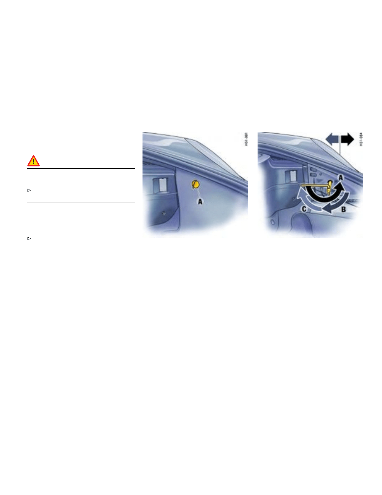
Headlights
Gener al information
Caution!
Risk of damage to headlights due to abrasion
and excessive temperatures.
Do not affix any coverings (e.g. “ stone guards”
or films) in the area of the headlights.
Note
The headlights can mist up depending on the
temper ature and h umidity.
To ensure optimum ventilatio n, do not cover
the gap between headlight and bo dy (e.g.
“stone guards” or films).
Removal
1. Unscrew plastic nut A. Detach side carpeting.
2. Remove rubber plugs from the unlocking
opening.
3. Place socket wrench (tool kit) o n the unlocking
spindle . The tongue of the wrench should point
horizontally to the rear.
4. Turn so cket wrench approx. 180° A. The
headlight is unlocked and pushed forward
slightly during this process.
5. Turn so cket wrench back until it is pointing
vertically downward B and leave in position.
6. The headlight i s now unlock ed and c an be
pulled forward out of th e fender.
Practical Tips, Emergency Service
271
Downloaded from www.ManualsFile.com manuals search engine
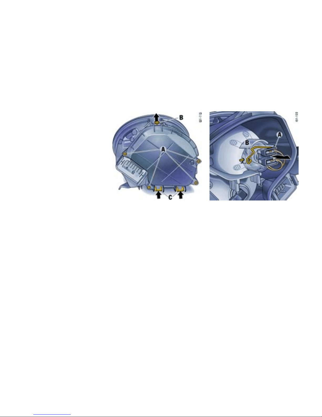
Installing
1. Insert headlight into the guide rails and push it
fully into the fender.
2. Push headlight to the rear and at the s ame
time turn the socket wrench until it points
horizontally to the rear C. The headlight
locking device must perceptibly and audibl y
engage.
3. Insert the r u bber plug into the unlocking
opening and secure the carpet. Chec k the
function of all lights.
Low beam, high beam and additional high
beam
Opening the lid of t he headlight housing
1. Unscrew the 4 screws A.
2. First lift release tab B, then push both release
tabs C upwards and take off lid.
Halogen headlights: Changing bulb f or low
beam
1. Pull off plug A.
2. Disengage fixing loop B.
3. Replace defective bulb. When doing so,
ensure bulb is seated properly.
4. Reassemble in reverse order.
272Practical Tips, Emergency Service
Downloaded from www.ManualsFile.com manuals search engine
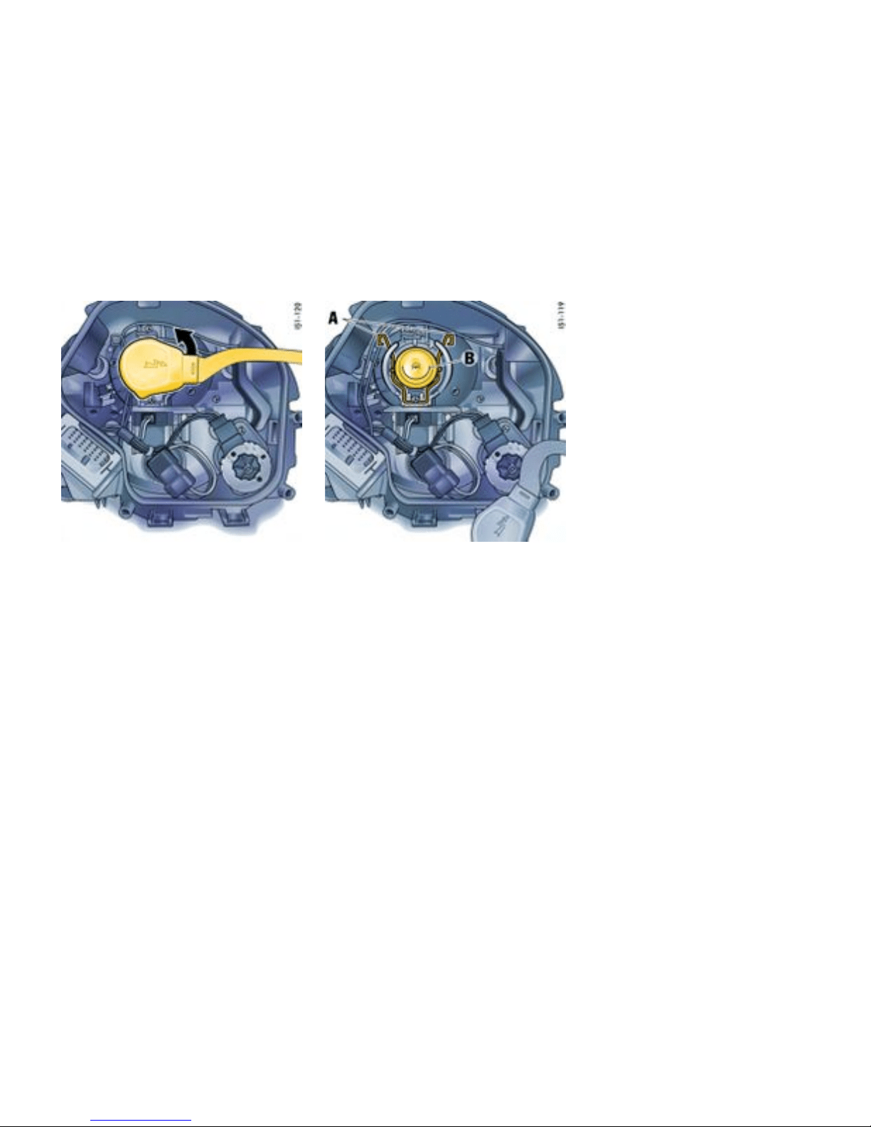
Bi-Xenon headlight : Changing bu lb for low
beam and high beam
1. Turn the plug counter-clockwise (bayone t lock)
and pull it off.
2. Disengage both fixing loops A.
3. Replace defe ctive bulb B. When doing so,
ensure bulb is seated properly.
4. Engage both fixing loops A, push on plug and
turn right as far as the stop.
Practical Tips, Emergency Service
273
Downloaded from www.ManualsFile.com manuals search engine
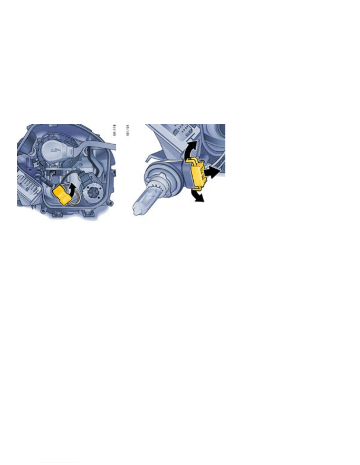
Changing bulb for high beam or a dditional hig h
beam (Bi-Xenon headlight)
1. Turn the bulb holder. Turn it count er-clockwise
on the left headlight and clockwis e on the right
headlight. Take bulb holder out of the headlight
housing.
2. Pull both plug release tabs apart. Pull plug out
of the bulb holder.
3. Replace the defecti ve bulb with bulb holder.
4. Reassemble in reverse order.
Closing lid of headlight housing
1. Push on lid until it percep tibly engages.
2. Fasten lid with the 4 screws.
274Practical Tips, Emergency Service
Downloaded from www.ManualsFile.com manuals search engine
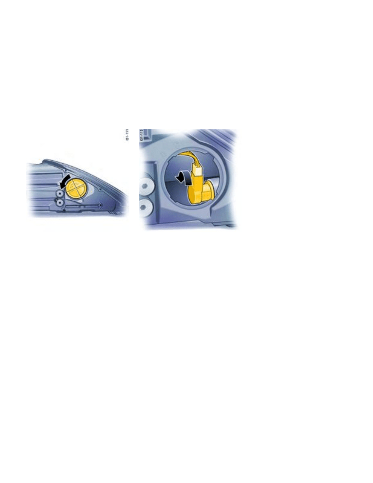
Turn sign al light
Changing bulb
1. Turn lid counter-clockwise and pull it off.
2. Turn bulb holder counter-clockwise (bayonet
lock).
3. Replace the defective bulb ( bayonet fitting).
4. Insert lamp holder and turn it clockwise.
5. Replace lid and close.
Practical Tips, Emergency Service
275
Downloaded from www.ManualsFile.com manuals search engine
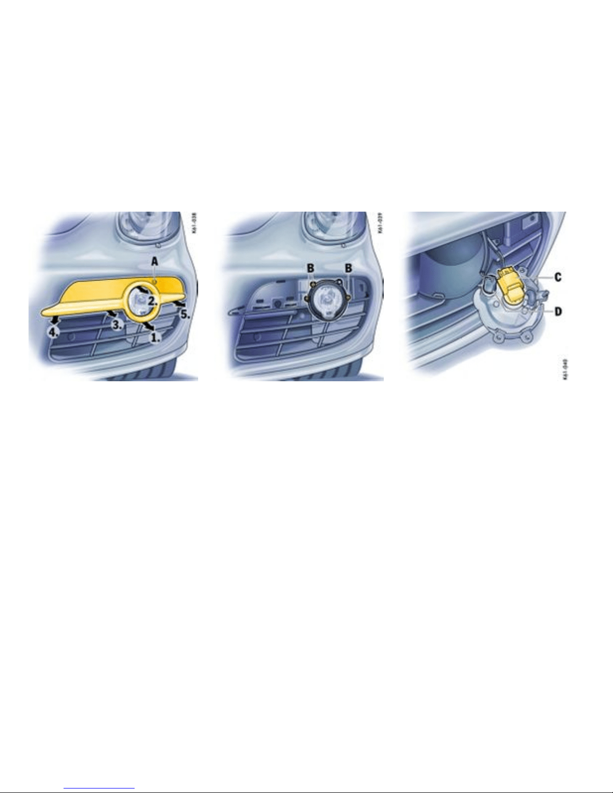
A - Fog light height adjustment
Fog light/parking light
Changing bulb
Based on the system, a relatively large amount
of effort is required to remove the light cover. In
case of doubt, please consult a qualified speciali st
workshop. We recommend an authorized Porsche
dealer for this work as they have trained workshop
personnel and t he necessary parts and tools.
1. Unclip the light cover using both hands,
beginning on the cover underneath the fog
light and then toward the center of th e vehicle.
2. Loosen the 3 screws B and take out the light
housin g.
C - Fog light
D - Parking light
276Practical Tips, Emergency Service
Downloaded from www.ManualsFile.com manuals search engine
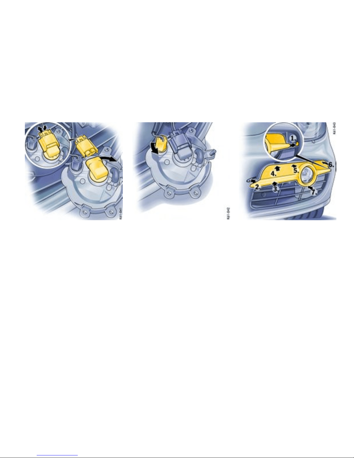
Changing fog light bulb
3. Press the release tab (arrow) of the plug and
pull plug off.
4. Turn bulb holder clockwi se (bayonet lock) and
remove holder.
5. Replace defective bulb.
6. Insert the bulb holder and turn it counter-
clockwise.
7. Push on plug until i t is felt to engage.
Changing parking li ght bulb
8. Turn bulb holder counter-clockwise (bayonet
lock) and remove holder.
9. Remove defective bulb and replace.
10. Insert the bulb holder and turn it clockwise.
11. Insert bulb housing and tighte n with th 3
screws B.
12. First insert the light cover into the side cut-out
1 and then press down the cover at points
2 - 7 one after the other. Make sure that the
frame is completel y clipped in.
13. Check operation of lights.
Practical Tips, Emergency Service
277
Downloaded from www.ManualsFile.com manuals search engine
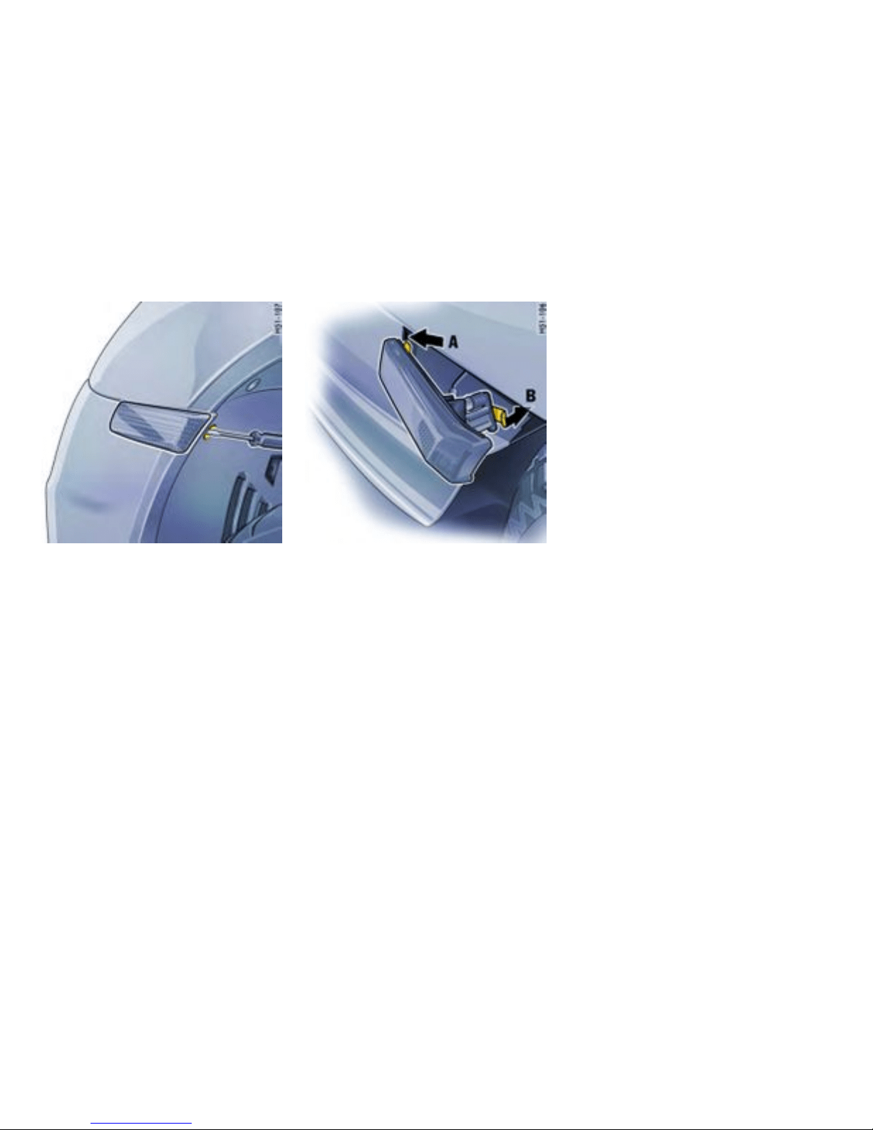
Side mark er light
Changing bulb
1. Remove the cap in the w heel housing liner with
a screwdriver.
2. Insert the screwdriver into the opening in
the wheel housing liner at right angles to the
turn signal housing. By pressing with t h e
screwdriver, disengage the securing spring
B of the direction indicator housing.
3. Swivel out the indicator light and undo bulb
holder (bayonet lock).
4. Remove the bulb from the holder and replace
it. Ins ert holder. Check operation of the light.
5. Insert the turn signal’s retaining lugs A into the
side section at the front. Push in turn signal
until the securing spring B is felt to engage.
6. Press the cap into th e wheel housing liner.
278Practical Tips, Emergency Service
Downloaded from www.ManualsFile.com manuals search engine
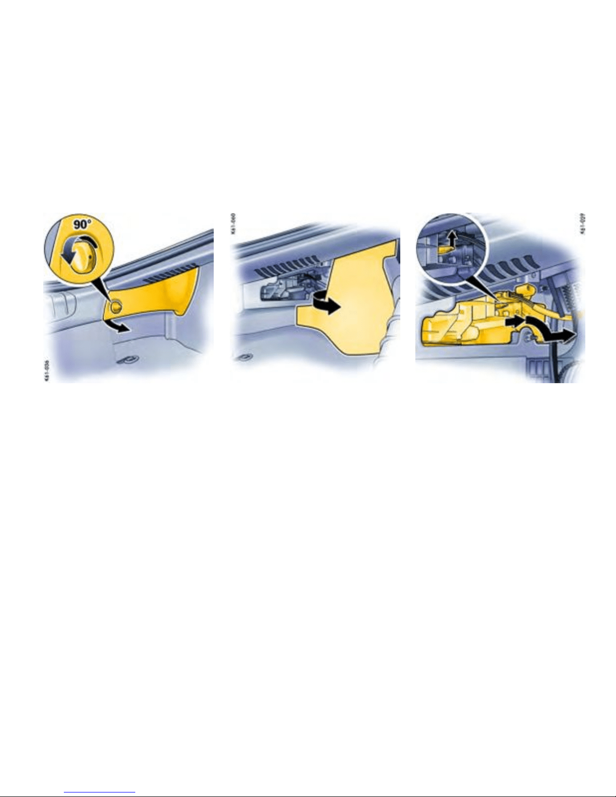
Tail light, left
Tail light
Changing bulbs
1. Turn lock of the light cover approx. 90° and
take off cover.
2. Pull out side carpeting. 3. Press the mounting of the lamp bracket
upwards. Pull the unlocked lamp bracket out a
little (approx. 0.7 9 in./2 cm), tip it downwards
slightly and then remove it fully.
Practical Tips, Emergency Service
279
Downloaded from www.ManualsFile.com manuals search engine

A - Turn si gnal light
B - Reversing light
C - Rear fog light, rear light
D - Tail light
E - Brake light, rear light
4. Replace the defectiv e bulb (bayonet fitting).
5. Insert lamp bracket. Make sure that the
mounting is felt to engage .
6. Refit side carpeting.
7. Insert the light cover into the three receptacles
and lock the cover.
8. Check opera tion of lights.
Additional brake light
The light-emitting diodes of the additional brake
light cannot be replaced individually.
Have the defective brake light replaced at an
authorized Porsche dealer.
280Practical Tips, Emergency Service
Downloaded from www.ManualsFile.com manuals search engine
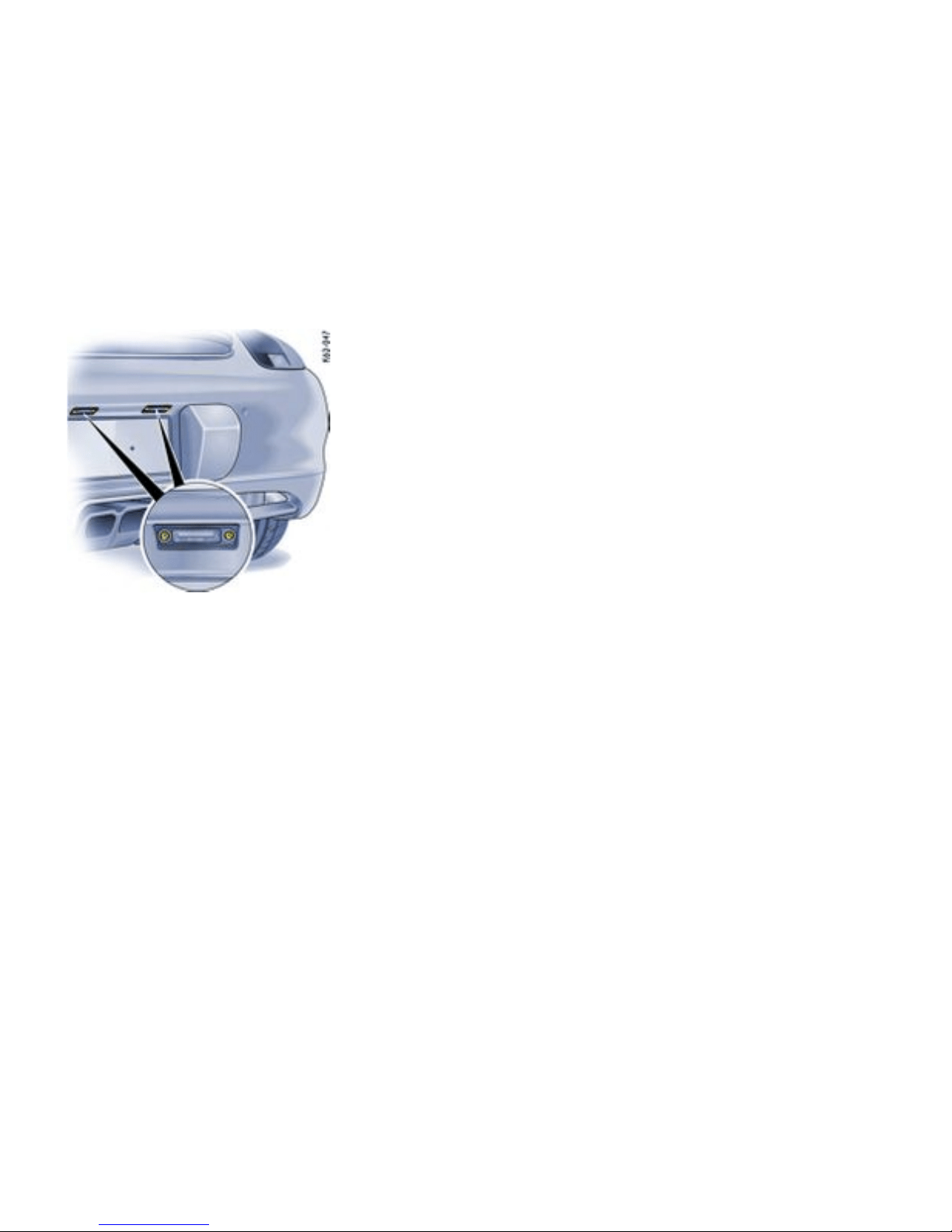
License plate ligh ts
Changing bulb
1. Unscrew both screws a n d remove the light
lens.
2. Remove defective bulb from between the
contact springs and replace it.
3. Reassemble in reverse order. Check operation
of the light.
Practical Tips, Emergency Service
281
Downloaded from www.ManualsFile.com manuals search engine
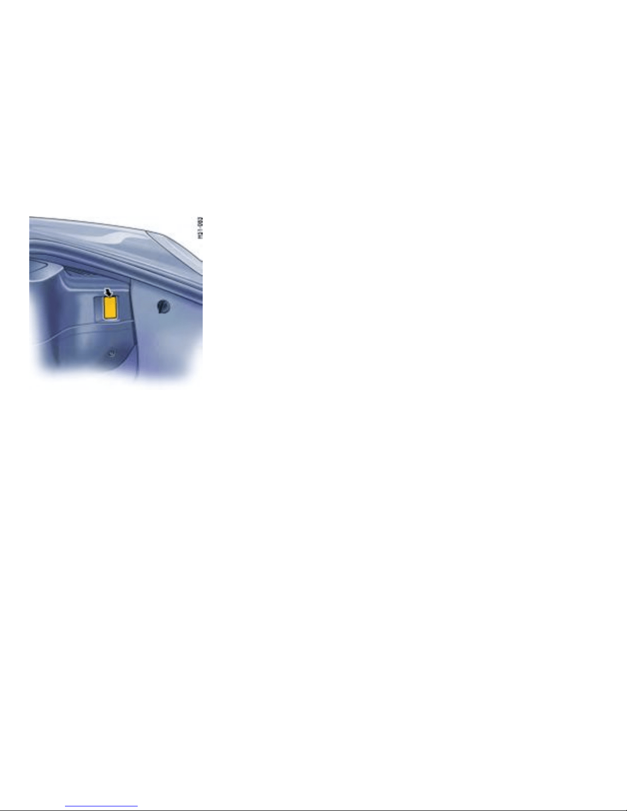
Example: Front luggage compartment light
Front luggage
compartment/footwell lights
Changing bulb
1. With a screwdriver (arrow), carefully push out
the light.
2. Remove defective bulb from between the
contact springs and replace.
3. Insert the light into the cut-out, first from one
side then from the other. Check operation.
282Practical Tips, Emergency Service
Downloaded from www.ManualsFile.com manuals search engine
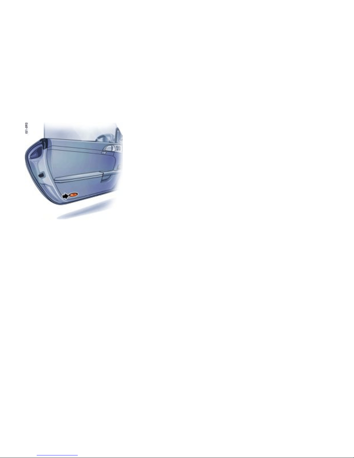
Door g uard/curb/rear luggage
compartment lights
Changing bulb
1. With a screwdriver (arrow), carefully pu sh out
the light.
2. Pull bulb holder out of light housing. Re move
defective bulb and replace.
3. Install bulb holder and insert the light.
Practical Tips, Emergency Service
283
Downloaded from www.ManualsFile.com manuals search engine
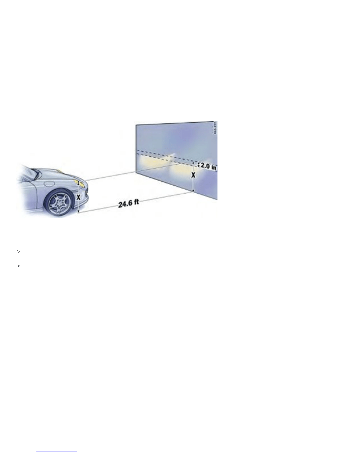
Adjusting Headlights
Adjustment
Please observe the chapter ”REPLACING
BULBS” on page 269.
Please observe the chapter ”TIRE PRESSU RE
FOR COLD TIRES” on page 299.
The adjustment is ma de with the vehicle ready to
drive and the fuel tank completely filled.
The driver’s seat must be loaded by a person or a
165 lbs. (75 kg) weight and the tire pressures must
meet the prescribed values. After being loaded,
the car must be rolled a few meters so that the
suspen sion can settle.
For checking the headlight adjustment, the vertical
position of the cutoff of the lowbeam (see fig.)
has to be projected on a vertical screen (wall) in
distance of 2 4.6 ft. (7.5 m) from the front lens of
the headlamp. The correct position of the cutoff
is 2.0 in. (5 cm) at 24.6 ft. or 7.5 m (0.4°) below a
horizontal line, x in. from ground to the center of
the headlamp lens.
284Practical Tips, Emergency Service
Downloaded from www.ManualsFile.com manuals search engine
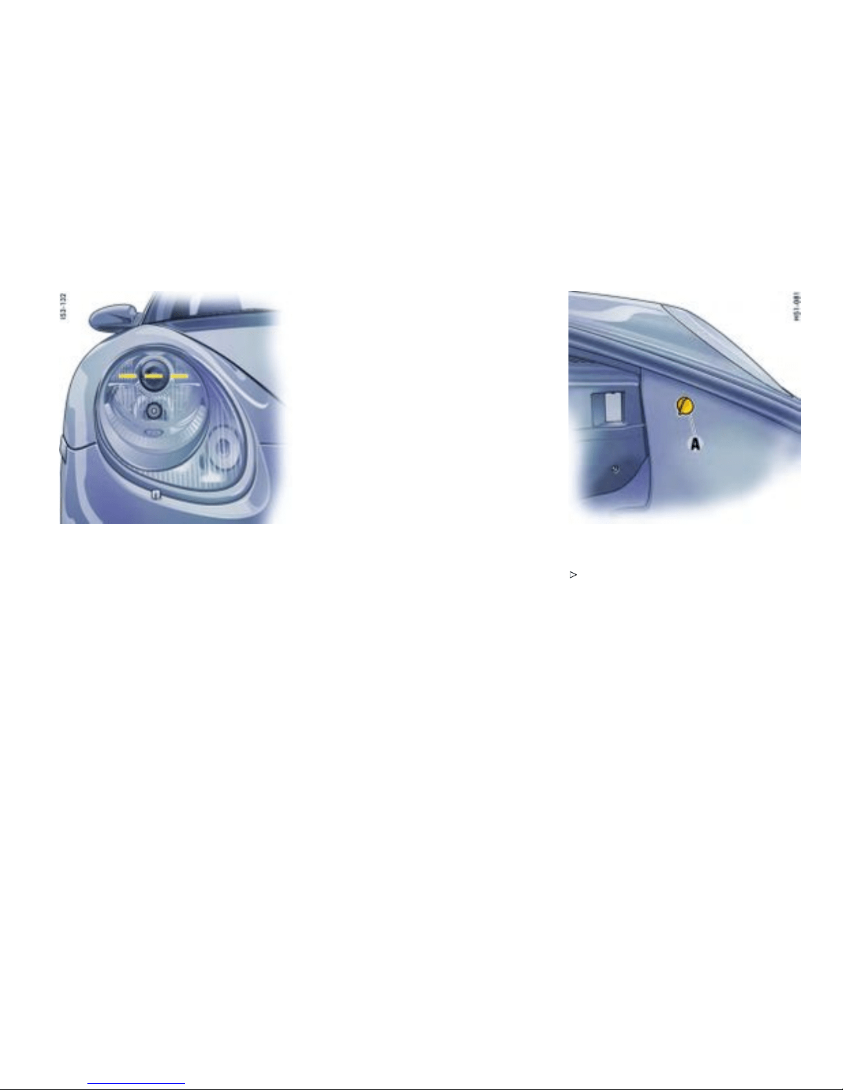
Lateral adjustment of the headlights should be
carried out at a sp ecialist workshop with an optical
adjustment unit.
Distance
Visual aim shall be performed at not less than
24.6 ft. (7.5 m) (this value is a rounded down
conversion from the 25-foot distance typical of
field aim using a screen). The 24.6 ft. (7.5 m)
distance is measured from the hea dlamp lens to
the viewing screen.
Floor
The surface upon which the vehicle rests is flat and
approximate ly l evel.
Screen
The screen upon which headlamp beams are
projected is perpendicular to the floor and th e
vehicle’ s longitudinal axis, flat, uniformly light in
color, unobs tructed, and wide and high enough
to accommodate the vehicle beam patterns to be
aimed.
The screen should be wide enough to provide
at least 3.3 ft. (1 m) of space outboard of the
vehicle’s headlamp spacing .
Adjustment screws
Detac h side carpe ting in luggage compart-
ment. Unscrew plastic nut A. Open the cover
of the appropriate adjustment screw. The set-
ting is adjusted by turning the hexagon socket
screws right or left, as a p propriate.
Practical Tips, Emergency Service
285
Downloaded from www.ManualsFile.com manuals search engine
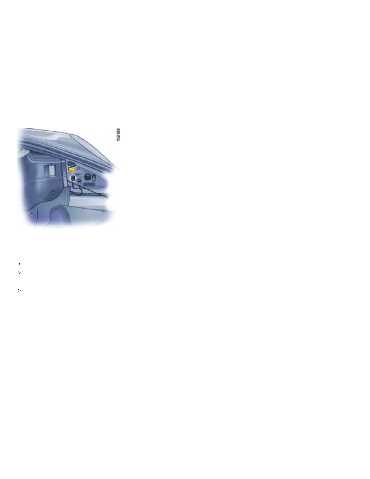

Towing
Gener al information
Certain state statutes and local ordinances prohibit
towing with a chain, rope or even a tow bar. In
addition, damage to your vehicle may result from
improper procedures. Consul t your authorized
Porsche dealer for details.
Vehicle t owing
Flat bed towing is the preferred type of towing
to be used on Porsche vehicles. Under certain
circumstances, wheel lifts may be used when the
vehicle will not roll. The vehicle must be towed
with all four wheels off the ground, otherwise
damage to the vehicle may result.
Towing hook
The towing hook A is stored in the tool box in the
luggag e compart ment.
Caution!
Risk of damage to the vehicle.
Use the towing hook only for an emergency to
remove the vehicle off the road. The towing
hook is to be used only to pull the ve hicle onto
the flat bed, tractor or to wing apparatus if the
vehicle will roll freely. Under no circumstances
is the vehicle to be secured using the towing
hook.
Never use the towing hook to tow this or an y
other vehicle.
Bear in mind the limited ground cl earence of
your car on uneven surfaces.
Practical Tips, Emergency Service 287
Downloaded from www.ManualsFile.com manuals search engine
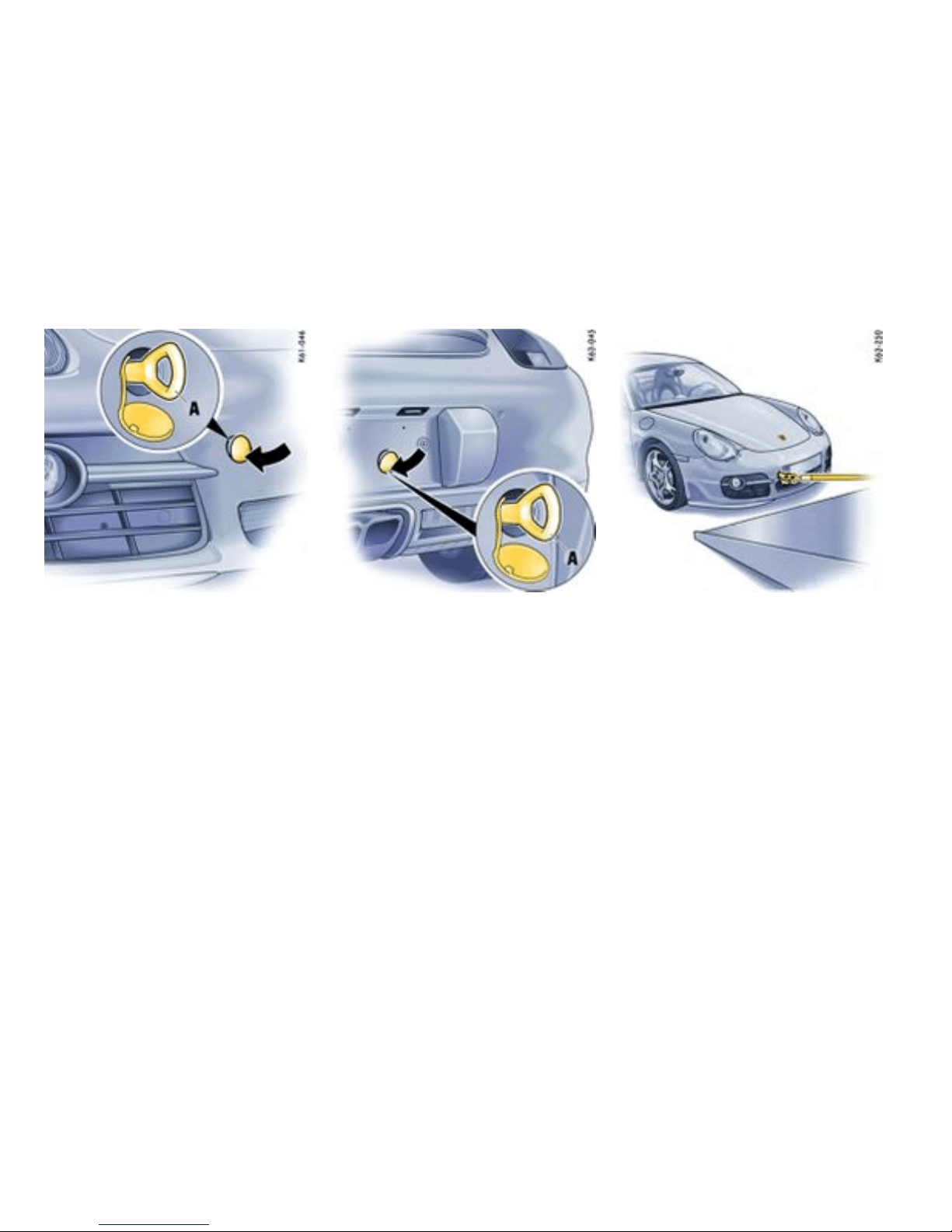
Fitting towing hook
When fitting on the rear of the vehicle, the license
plate must be removed.
1. Press the lower edge of the appropriate
plastic cover into the bumper until the cover
disengages.
2. Pull cover out of the bumper and l et it hang by
its thread.
3. Comple tely screw in the towing hook A.
Removing towing hook
1. Unscrew the towing hook A.
2. Insert plastic cover at th e lowe r edge of the
opening.
3. Fold the cover up and press on its upper edge
to engage it in the bumper.
When removing on the rear of the vehicle, the
license plate must be mounted.
Pulling ve hicle onto at bed
1. Position wooden ramps at the base of the flat
bed to reduce the angle of the pull.
2. Reel in the hoist cable and check the underside
of the vehicle for any interference.
288Practical Tips, Emergency Service
Downloaded from www.ManualsFile.com manuals search engine
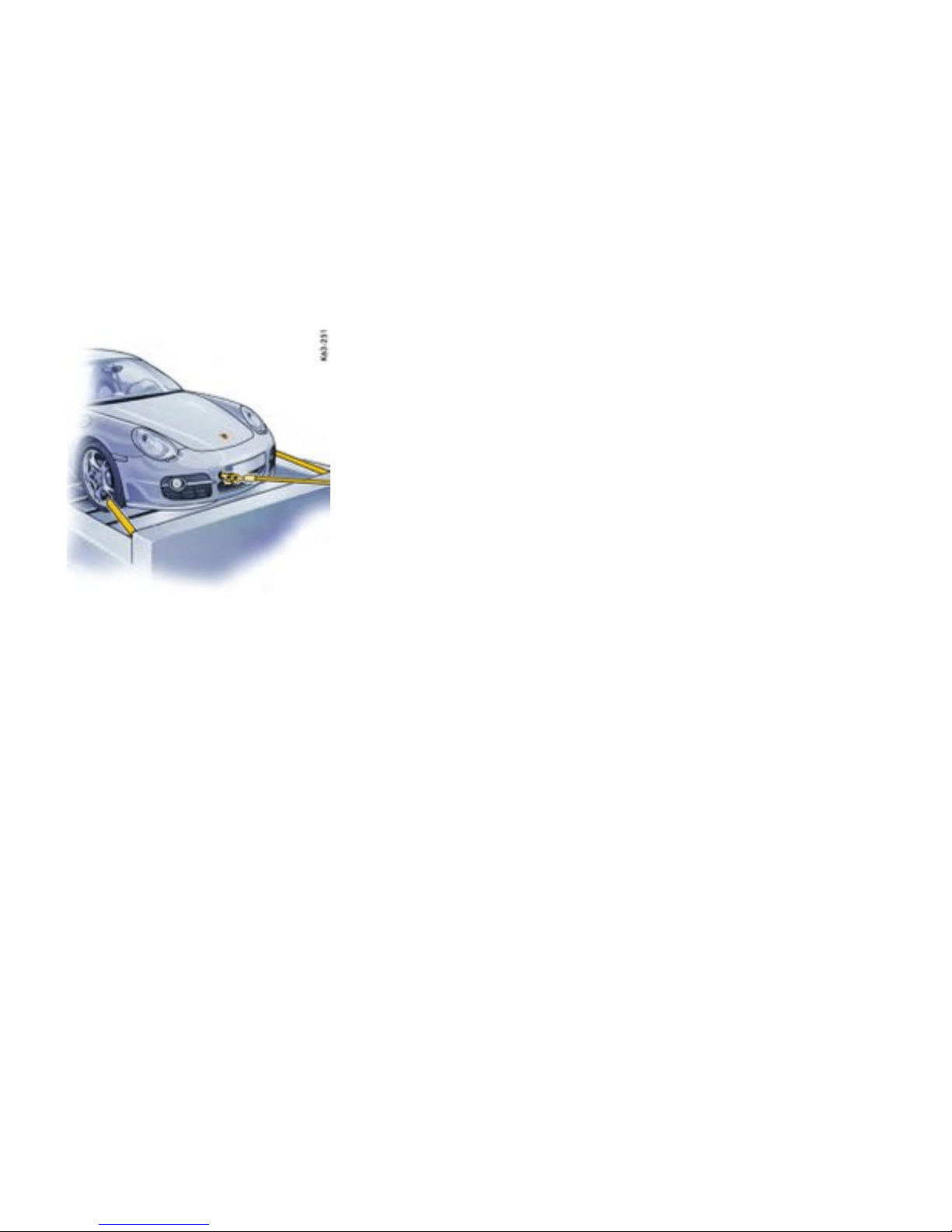
Tying down vehicle on at bed
1. Carefully feed towing straps through the
opening in the rear wheels. Make sure metal
par ts of st raps do not damage rim. Make sure
the strap is flat over the rim bead. Mak e sure
brake backing p late is not damaged.
2. Secure straps to rear of flat bed.
3. Reel in hoist cable only far e nough to tension
tie-down straps.
4. Carefully feed towing straps through the
opening in the front wheels. Make sure metal
par ts of st raps do not damage rim. Make sure
the strap is flat over the rim bead. Mak e sure
brake backing p late is not damaged.
5. Secure straps to front of flat bed.
6. Release tension on hoist cable, but do not
disconn ect. Use hoist cable as a safety cable.
Practical Tips, Emergency Service
289
Downloaded from www.ManualsFile.com manuals search engine


Vehicle Identication
Ordering spare parts
When ordering spare parts or making inquiries,
please always quote the vehicle ident ification
number.
Vehicle data bank
The vehicle data bank is attached to the inside of
the ”Maintenance“ booklet. It c ontains all import ant
data about your car.
Note
This data bank cannot be re-ordered i f it is lost
or damaged.
This label contains the following information:
1. Vehicle Identification No.
2. Type/Ty pe description
3. Engine code/Tr ansmission code
4. Paint No./Interior
5. Optional equipment
Vehicl e identication number
Position
In accordance with Federal Safety Regul ations, the
vehicle identification numb er of your c ar is located
at the bottom left of the windshield frame and can
be seen from the outside.
The vehicle identification number is in the front
luggage com p artment under the battery cover and
at the bottom left behind the windshield.
Removing t h e battery cover
Please observe the c hapter ”BATTERY” on
page 262.
Safet y compliance sticker
The safety compliance sticker is your a ssurance
that your new Porsche complies with all applica-
ble Federal Motor Vehicle Safety Standards which
were in effect at the time the vehicle was manufac-
tured.
The sticker also shows the month and year of
production and the vehicle identification number of
your car (perforations) as well as the Gross Vehicle
Weight Rating and the Gross Axle Weight Rating.
292Vehicle Identificati on, Technical Data
Downloaded from www.ManualsFile.com manuals search engine
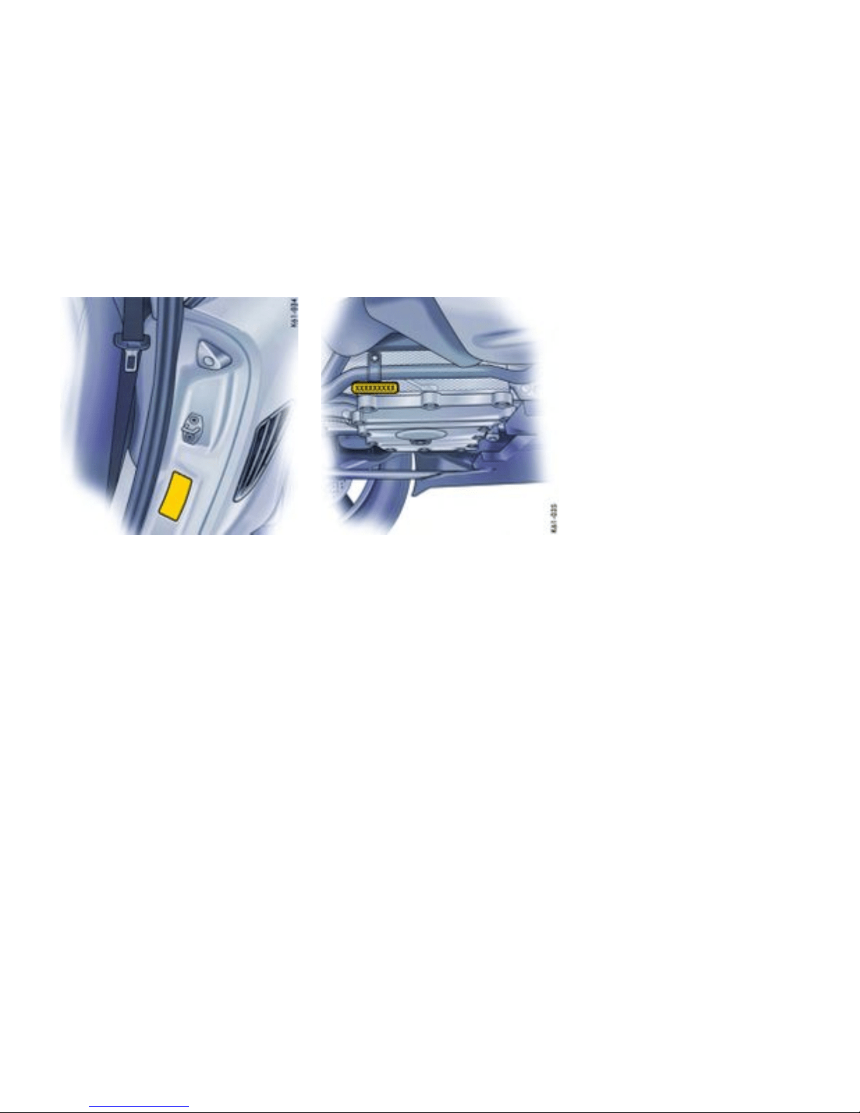

Technical Data
Engine data
Cayman Cayman S
Type
M 97/20
Horizontally opposed engine, liquid coole d
M 97/21
Horizontally opposed engine, liquid cooled
Number of cylinders 6 6
Bore
3.37 in./85.5 mm 3.78 in./96 mm
Stroke 3.07 in./78 mm 3.07 in./78 mm
Cubic capacity 163.96 cu.in./2687 cm³ 206.67 cu.in./3387 cm³
Net-horsepower, SAE J 1349 245 hp/180 kW 295 hp/217 kW
at crankshaft speed 6500 rpm 6250 rpm
Net torque, SAE J 1349 201 ft.lb./273 Nm 251 ft.lb./340 Nm
at crankshaft speed 4600 - 6000 rpm 4400 - 6000 rpm
Engine oil consump tion
up to 1.5 liters/1000 km (1.6 quarts/622 miles) up to 1.5 liters/1000 km (1.6 quarts /622 miles)
294Vehicle Identificati on, Technical Data
Downloaded from www.ManualsFile.com manuals search engine

Transmissi on
Gear ratios Cayman 5-sp eed
manual transmission
6-speed
manual transmission
Tiptronic S
1st gear 3.50 : 1 3.67 : 1 3.66 : 1
2nd gear 2.12 : 1 2.05 : 1 2.00 : 1
3rd gear 1.43 : 1
1.41 : 1 1.41 : 1
4th gear
1.09 : 1 1.13 : 1 1.00 : 1
5th gear
0.84 : 1 0.97 : 1 0.74 : 1
6th gear 0.82 : 1
Reverse
3.44 : 1 3.33 : 1 4.10 : 1
Final drive ratio
3.75 : 1 3.88 : 1 4.38 : 1
Vehicle Identification, Technical Data
295
Downloaded from www.ManualsFile.com manuals search engine

Transmissi on
Gear ratios Cayman S 6-speed
manual transmission
Tiptronic S
1st gear 3.31 : 1 3.66 : 1
2nd gear 1.95 : 1 2.00 : 1
3rd ge ar
1.41 : 1 1.41 : 1
4th gear
1.13 : 1 1.00 : 1
5th gear
0.97 : 1 0.74 : 1
6th gear 0.82 : 1
Reverse
3.00 : 1 4.10 : 1
Final drive ratio
3.88 : 1 4.16 : 1
296Vehicle Identificati on, Technical Data
Downloaded from www.ManualsFile.com manuals search engine

Tires, Rims, Tracks
Cayman
Tire Rim Rim off set Track
Summer tires front 205/55 ZR 17 (91Y) 6.5 J x 17 H2
55 mm
58.7 in./1490 mm
rear
235/5 0 ZR 17 (96Y) 8 J x 17 H2 40 mm 60.4 in./1534 mm
or
front 235/40 ZR 18 (91Y) 8 J x 18 H2
57 mm
58.5 in./1486 mm
rear
265/4 0 ZR 18 (101Y) XL 9 J x 18 H2 43 mm 60.2 in./1528 mm
or
front 235/35 ZR 19 (87Y) 8 J x 19 H2
57 mm
58.5 in./1486 mm
rear
265/35 ZR 19 (94Y) 9.5 J x 19 H2 46 mm 60.0 in./1522 mm
Snow tires front 205/5 5 R 17 91V M+S 6.5 J x 17 H2
55 mm
58.7 in./1490 mm
rear
235/5 0 R 17 96V M+S * 8 J x 17 H2 40 mm 60.4 in./1534 mm
or
front 235/40 R 18 91V M+S 8 J x 18 H2
57 mm
58.5 in./1486 mm
rear
255/4 0 R 18 95V M+S * 9 J x 18 H2 43 mm 60.2 in./1528 mm
Vehicle Identification, Technical Data
297
Downloaded from www.ManualsFile.com manuals search engine

Tires, Rims , Tracks
Cayman S
Tire Rim Rim off set Track
Summ er tires front 235/40 ZR 18 (91Y) 8 J x 18 H2
57 mm
58.5 in./1486 mm
rear
265/4 0 ZR 18 (101Y) XL 9 J x 18 H2 43 mm 60.2 in./1528 mm
or
front 235/35 ZR 19 (87Y) 8 J x 19 H2
57 mm
58.5 in./1486 mm
rear
265/3 5 ZR 19 (94Y) 9.5 J x 19 H2 46 mm 60.0 in./1522 mm
Snow tires front 235/40 R 18 91V M+S 8 J x 18 H2
57 mm
58.5 in./1486 mm
rear
255/40 R 18 95V M+S * 9 J x 18 H2 43 mm 60.2 in./1528 mm
The load capacity coeff icient (e.g. “91”) and maximum speed code letter (e.g. “V”) are minimum requirements.
Please observe the chapter ”TIRES/WHEELS” on page 237.
Danger!
Installation of sizes not authorized by Porsche may have a dangerous effect on the dri v ing stability and could result in severe personal injury or
death.
Before mounting new tires, check with your Porsche dealer about the current release status.
Tire and rim sizes
Extensive tests are performed before specif ic tires and wheels are app roved by Porsche. Your Porsche dealer has informat ion
about approved tires an d wheels and i s happy to assis t you. If aftermarket tires and/or wheels are installed which are not approved
by Porsche, the vehicle’s driveability, stability while in motion and handling chara cteristics migh t be impaired. Since Porsche has
no data on such combinations, Porsche cannot stand behind the safety or durability of these aftermarket combinations.
Snow chains * Can be mounted only on the rear wheels; maximum speed 30 mph/50 km/h. Use only Porsche authorized fine-link cross-type
or edge chains. Sn ow chain clearance can be guaranteed only with the tire + rim combination marked.
298Vehicle Identificati on, Technical Data
Downloaded from www.ManualsFile.com manuals search engine

Tire pressure for cold tires
Summ er and snow tires
17 inch and 18 inch wheels front 29 psi (2.0 bar)
rear
36 psi (2.5 bar)
19 inch wheels front 32 psi (2.2 bar)
rear
36 psi (2.5 bar)
These tire pressures apply only to the tire makes and types approved by Porsche.
Please observe the c hapter ”TPC TIRE PRESSURE MONITORING” on page 122.
Pleas e observe the chapter ”TIRES/W H EELS” on page 237.
Vehicle Identification, Technical Data
299
Downloaded from www.ManualsFile.com manuals search engine

Driving Performance
At DIN empty weight and half load, without performance-inhibiting extra equipment.
Cayman
5–speed manual transmission
6–speed manual transmission Tiptronic S
Top track speed
160 mph/258 km/h 162 mph/260 km/h 157 mph/253 km/h
Accelerat ion 0 - 60 mph 5.8 seconds 5.8 seconds 6.7 seconds
Acceleration 0 - 100 km/h (62 mph) 6.1 seconds 6.1 seconds 7.0 seconds
Cayman S 6–speed manual transmission Tiptronic S
Top track speed
171 mph/275 km/h 166 mph/267 km/h
Acceleration 0 - 60 mph
5.1 seconds
5.8 seconds
Acceleration 0 - 100 km/h (62 mph)
5.4 seconds
6.1 seconds
300Vehicle Identificati on, Technical Data
Downloaded from www.ManualsFile.com manuals search engine

Capacities
Use only fluids and fuels authorized by Porsche. Your authorized Porsche dealer will gladly advise you.
Your Porsche has been designe d so that it is not necessary to mix any additives with oils or fuels.
Engine
Oil change quantity without oil filter approx. 1.98 U.S.gallons/7.5 liters
Oil change quantity with oil filter approx. 2.05 U.S.gallon s/7.75 liters
Please observe the c hapter ”ENGINE OIL RECOMMENDATION” on page 210.
Coolant Cayman: Manual transmission approx. 5.81 U.S.gallons/22 liters; Tiptronic S: approx. 5.92 U.S.gal-
lons/22.4 liters
Cayman S: Manual transmission approx. 5.89 U.S.gallons/2 2.3 liters; Tiptronic S: approx. 6.42 U.S.gal-
lons/24.3 liters
Manua l tran smission and differential
5-spee d: approx. 2.4 quarts/2.25 liters; 6-speed: approx. 3 quarts/2.8 liters
Tiptronic S approx. 2.5 U.S.g allons/9.5 liters
Differential with Tiptronic S approx. 0.21 U.S.gallons/0.8 liters
Power steer i ng
approx. 1.1 quarts/1 liter hydrau lic fluid Pentosin CHF 11 S
®
or Pentosin CHF 202
®
Brake uid
approx. 0.4 quarts/0.39 liters; use only Original Porsche brak e fluid
Windshield washer
approx. 0.66 U.S.gallons/2.5 liters without headlight washer
approx. 1.58 U.S.gallons/6 liters with headlight washer
Fuel tank
Refill volume approx. 16.9 U.S.gallons/64 liters, including approx. 2.6 U.S.gallons/10 liters reserve.
Fuel quality
Your engine is designed to provide optimum performance and fuel economy using unleaded premium
fuel with an octane rating of 98 RON (93 CLC or AKI).
Porsche therefore recommends the use of these fuels in yo ur vehicle.
Porsche also recognizes that these fuels may not always be available. Be assured that your vehicle will
operate properly on unleaded premium fuels with octane numbers of at least 95 R ON (90 CLC or AKI),
since the engine’s “Electronic Octane™ knock control” will adapt the ignition timing, if necessary.
Vehicle Identification, Technical Data
301
Downloaded from www.ManualsFile.com manuals search engine

Weights
Cayman
Manual tran smission
Tiptronic S
Empty weight (depe nding on equipment) 2866 lbs. to 3131 lbs. 2998 lbs. to 3230 lbs.
1300 kg to 1420 kg 1360 kg to 1465 kg
Maximum gross weight
3571 lbs./1620 kg 3671 lbs./1665 kg
Maximum axle l oad, front
1)
1709 lbs./775 kg 1709 lbs./775 kg
Maximum axle l oad, rear
1)
2017 lbs./915 kg 2017 lbs./915 kg
Maximum useful load, Roof Transport System
2)
132 lbs./60 kg 132 lbs./60 kg
Cayman S
Manual tran smission
Tiptronic S
Empty weight (depe nding on equipment) 2976 lbs. to 3153 lbs. 3064 lbs. to 3241 lbs.
1350 kg to 1430 kg 1390 kg to 1470 kg
Maximum gross weight
3594 lbs./1630 kg 3682 lbs./1670 kg
Maximum axle l oad, front
1)
1709 lbs./775 kg 1709 lbs./775 kg
Maximum axle l oad, rear
1)
2072 lbs./940 kg 2072 lbs./940 kg
Maximum useful load, Roof Transport System
2)
132 lbs./60 kg 132 lbs./60 kg
If additional accessories are installed, the useful load will be correspondingly less.
1)
The maximum gross weight must not be e xceeded.
2)
Use only Original Porsche Roof Transport System
302Vehicle Identificati on, Technical Data
Downloaded from www.ManualsFile.com manuals search engine

Dimensio ns
Cayman PASM
Length
172.1 in./4372 mm
Width
70.9 in./1801 mm
(with door mirrors) 76.3 in./193 7 mm
Height
51.4 in./1305 mm 51.0 in./1296 mm
Wheelbase
95.1 in./2415 mm
Ground clearance
1)
4.2 in./107 mm 4.1 in./103 mm
Turning circle
36.4 ft./11.1 m
Cayman S PASM
Length
172.1 in./4372 mm
Width
70.9 in./1801 mm
(with door mirrors) 76.3 in./193 7 mm
Height
51.4 in./1305 mm 51.0 in./1296 mm
Wheelbase
95.1 in./2415 mm
Ground clearance
1)
4.1 in./104 mm 3.9 in./100 mm
Turning circle
36.4 ft./11.1 m
1)
At maximum gross weight.
Vehicle Identification, Technical Data
303
Downloaded from www.ManualsFile.com manuals search engine
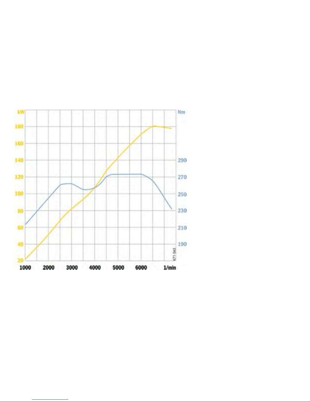
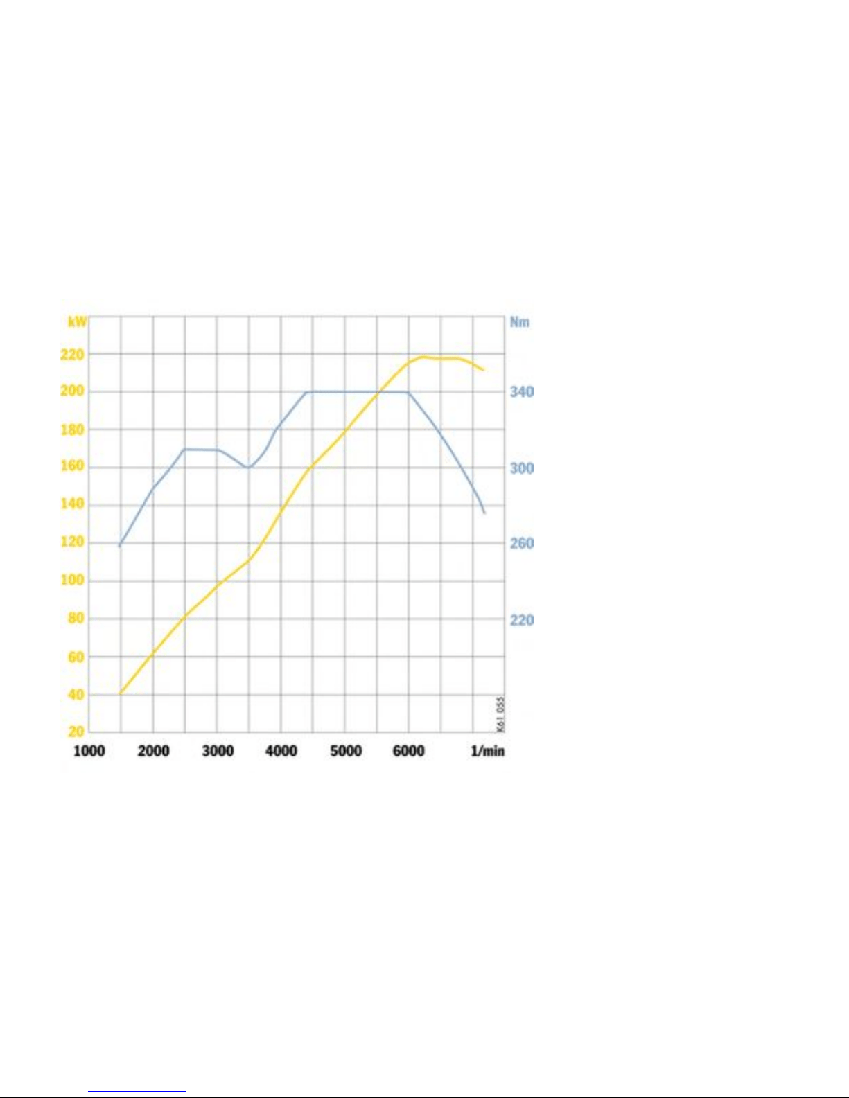
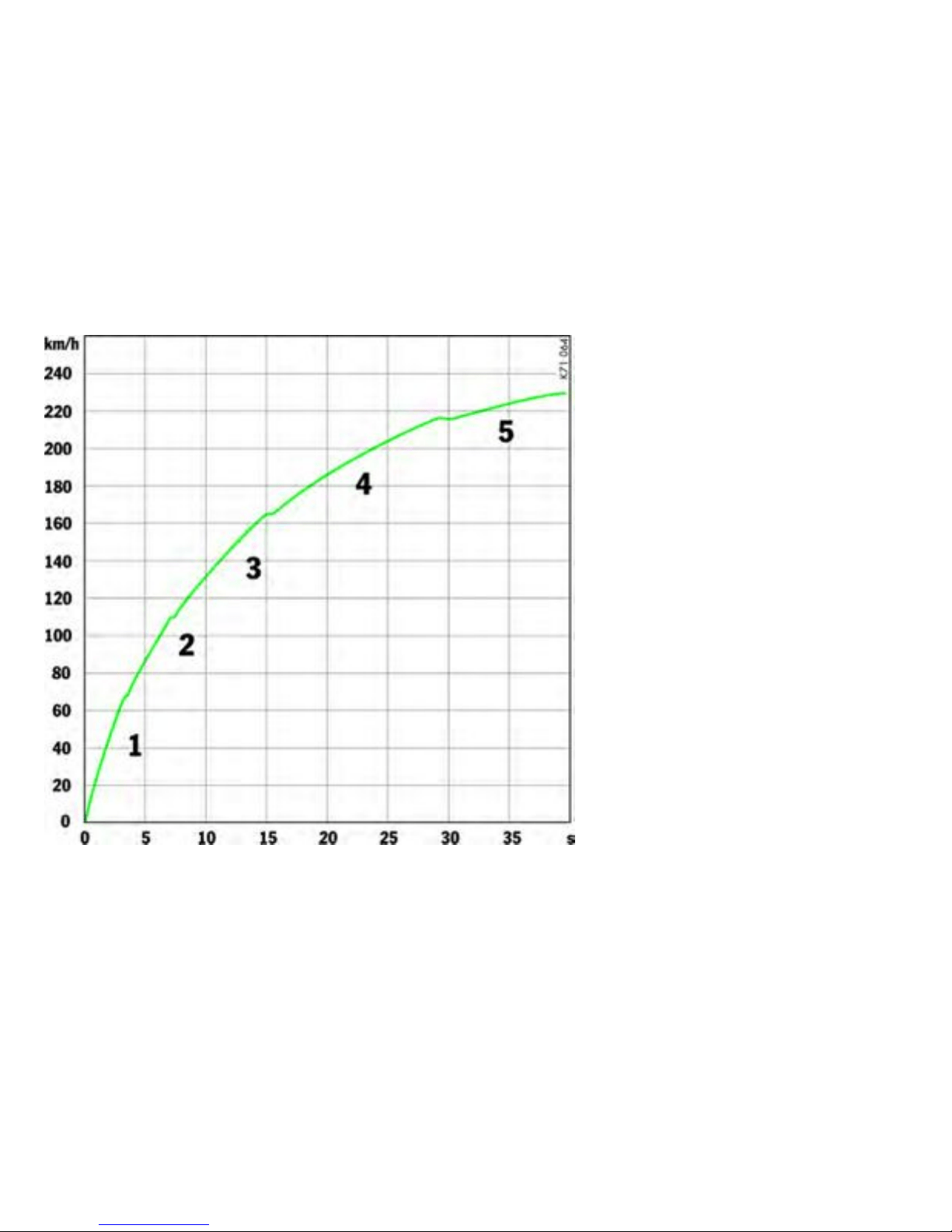
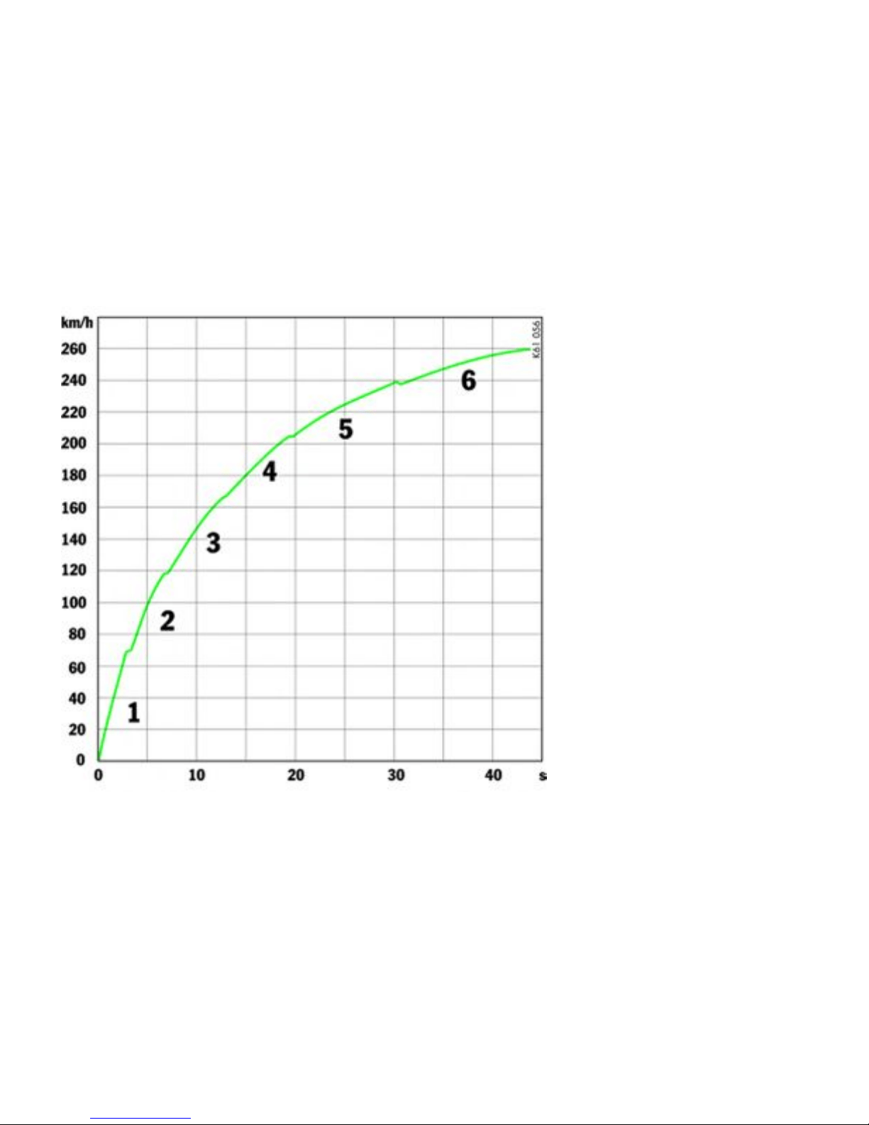

Index
A
ABS (antilock brake system) ........................... 69
Advanced Airbag ........................................... 53
Air conditioning ........................................... 156
Air distribution .................................... 156, 159
Air filter ........ .............................................. 225
Air-conditioning compressor ................. 158, 161
Airbag ........................................ .................. 52
Function ................................................. 53
Warning light ........................................... 55
Ais conditioning ........................................... 159
Alarm system .............................................. 186
Alcantara ....................... ............................ 233
Antenna ................. ............................ 186, 229
Antilock brake system .................................... 69
Warning light ........................................... 69
Ashtray ...... ................................................ 164
Assistant ...................................................... 79
Audio operation ........................................... 185
Auto-button air conditioning ......................... . 159
Automatic
Anti-glare mirrors .................................... 37
Car washes .......................................... 228
Door locking ........................................... 30
Headlight beam adjustment .................... 148
Speed control ......................................... 92
Automat i c air conditioning system ................. 159
Average consumption ..................... ..... 1 06, 137
Average speed .................. .................. 1 06, 137
B
Backrest
Adjustment ........................................ ..... 41
Release ................................................. 42
Battery ................. ...................................... 262
Care ............................................... ..... 263
Charge stat e ......................................... 263
Putting vehicle into operation .................. 264
Remote control ..................................... 266
Removing ............................................. 265
Warning light ......................................... 101
Winter operation ..................... .............. 264
Before driving off ..................................... 16, 17
Blower adjustment .............................. 156, 159
Brake light .......................................... 279, 280
Brakes
Brake pad warning light .......................... 104
Fluid ............................................ 212, 301
Fluid warning light ............................. ..... 213
Pads ................................................ 19, 68
Test stand .............................................. 75
Break in hints ................................................ 19
Bulbs
Chart ................................. .................. 270
Replac ing ..................................... 269, 270
C
Canholder .................................................. 170
Capacit ies, overview . ................................... 301
Car care .......... ........................................... 202
Car telephone ............................................. 186
Car washes .................................... ............ 228
Cargo partition ............................................ 180
Catalyt ic converters .................................... 221
Cautions ............................................ 202, 236
Central locking ........................................ 25, 28
Emergency operation ........................ 25, 29
Central vents ......... ..................................... 162
Central warning light .................................... 103
Changing wheels
Assembly aids for wheel changes .. .......... 255
Check engine
Warning light ......................................... 102
Checkin g pressure .......................... ............ 256
Child Restraint Anchorage .............................. 63
Child restraint systems .................................. 58
Chime .............. .......................................... 147
CHRONO Stopwatch ....... ............ ................. 115
Circulating-air butto n ............................ 156, 159
Clock ................................................. 100, 136
Clutch ........................................................ 194
Clutch pedal ................................................. 64
Combination filter ........ ................................ 225
Comfort seat ...................... ............ ............. . 40
Coming Hom e mode .................................... 147
Compact disc
Holder ................................................. 168
Player .................................................. 186
Storage ................................. .............. 176
308Index
Downloaded from www.ManualsFile.com manuals search engine

Compressor ............................................... 176
Coolant ........................................ 97, 205, 301
Level ................................................... 205
Temperature gauge ................................. 97
Warning light ........................................... 97
Cooling system ..................................... 97, 205
Cruise control ............................................ ... 92
Cupholder .................................................. 170
D
Dashboard ................................................... 82
Data bank ........................... ........................ 292
Defrosting windows ....................... ...... 156, 159
Diagno stic socket ................................. 19, 259
Diagrams ........................................ ........... 303
Dimensions ..................................... ........... 303
Dipped beam ......................... ..................... 271
Door ............................................................ 31
Guard lights .......................................... 283
Handles ............................... .................. 31
Locks ............................................ 31, 229
Mirror heating ......................................... 38
Windows ................. ................. 31, 34, 231
Driving hints ............ ............ .......................... 15
Driving in winter ................. ............ ............. . 199
Driving performance .................................... 300
Drop-center rim ........................................... 247
DVD Navigation ........................................... 176
E
Electrical system ......................................... 259
Emergency flasher ...................................... 163
Emergency operation .................................... 29
Central locking ........ ......................... . 25, 29
Lids ................................... .................. 260
Tank cap .............................................. 217
Emergency program, Tiptronic ........ .. ........... 199
Emergency service ...................................... 236
Emergency starting with jumper cables .... ...... 268
Emission control system ........... 7, 102, 220, 221
Engine
Checking the oil level .... ......................... 131
Compartment ............................... 2 02, 236
Compartment blower ......................... 87, 97
Exhaust .............. ..................................... 9
Number ................. ............ ............. ..... 293
Oil consumption ...................................... 19
Oil level indicator ................................... 131
Oils .... .................................................. 301
Speeds .................................................. 19
Starting ................................................. 83
Switching off .......................................... 83
Environment ................................................... 6
F
Fire extinguisher ........................... ............ ... 172
Flat tire........................................ ............... 250
Floor mats .................................................. 233
Fog lights ............................... .... 147, 276, 279
Footw ell light ........................................ 81, 282
Front lid ........................ .............................. 174
Trunk entrapment .................................. 173
Front luggage compartment ..... .................... 176
Fuel ................................................. 5, 99, 216
Containers ............................................... 8
Econom y ... ............ ............. ............ ..... 214
Evapo ration .......................................... 222
Level gauge ............................................ 99
Level warning light ................................... 99
Portable Containers .............................. 218
Recommendation .................................. 219
Tank ............................................ 216, 217
Function keys .................................... ............ 47
Fuses ......................................................... 259
G
Garage door opener .................................... 188
Garage lift ................................... ............... 253
Gearchanging ...................................... ....... 194
Glove compartment ..................................... 167
Gong ...................................... 21, 85, 108, 147
Ground clearance ............................................ 9
H
Handbrake ................................................... 65
Hands-free microphon .................................. .. 82
Headlights .......................................... 149, 271
Adjusting ...................................... 284, 285
Cleaning system ........................... 150, 301
Headlig ths
Cleaning system ................................... 223
Heated rear window ....................................... 38
Heating .... .......................................... 156, 159
High beam
Indicator light .......................................... 96
Index
309
Downloaded from www.ManualsFile.com manuals search engine

Lever .................. ......................... 147, 149
Home mode .................... ............................ 147
HomeLin k ................................................... 188
Hoods ........................................ 173, 174, 178
Horn ...................................................... 19, 28
I
Identificat io n number ................. .................. 292
Ignition lock .................................... 83, 87, 195
Immob ilizer .................................................. 22
Instrum ent
Illumination ............................................. 93
Lights ........................... ....................... 147
Panel ........ ............................................. 88
Interior lights ...................................... .. 81, 283
Interior mirror ............................................... 36
J
Jumper cables ................ .................... 267, 268
K
Keylock ...................................................... 195
Keys ............................................................ 22
with remo te control .................... ............. 23
L
LATCH System .............................................. 62
Leather care ............................................... 233
License plate light ..................... .................. 147
Lids ............................ ............... 173, 174, 178
Emergency unlocki ng ............................ 260
Lifting the vehicle .................................. ...... 252
Light
Flasher .................................. 96, 147, 149
Low beam ...... .............................. 1 47, 149
Switch ............................... .................. 149
Light alloy wheels ........................................ 232
Inscription ......................................... ... 247
Load switch-off .................. ............ ............. 259
Loading information ..................................... 248
Locking .................................................. 26, 29
Luggage compartment ................. ............... 282
Cover .................................................. 182
Lids ............................................. ........ 174
Net ...................................................... 179
Luggage compartment lights ................... ....... 81
M
Maintenance .. ........................................ ..... 202
Make-up mirror .............................................. 48
Maximu m permitted engine speeds ..... . ... 19, 194
Mirrors ......................................................... 36
Anti-glare ................................................ 37
Multi-F unctional steering wheel
Function keys .............. ............ ............. .. 47
N
Navigation .................................................. 184
Notes on
Car care .................................. ............. 228
Maintenance ......................................... 202
Number plate ligh t .......................... ..... 147, 281
O
Octane rating .............................................. 219
Off delay ........ ............................................ 147
Oil ............................................................. 301
Checking level ...................................... 131
Consumption . ............ ............................. 19
Level checks .................. ...................... 208
Level indicator ........... ............. .............. 131
On-board computer ................................. 8, 105
Basic settings ....................................... 134
Language versions ................................ 136
On-board literature .... ............ ............. ............ . 1
Outside temperatur indicator ........................ 100
P
Paint
Care ................................................ .... 228
ParkAssistant ............................................... 79
Parking
Aids ....................................................... 79
Assistant ................................................ 80
Brake ........................................... ......... 65
Light .................................................... 147
Particle filter ............................................... 225
Plastic parts ............................................... 232
Platform lift ................................................. 253
Porsch e Active Suspension Management
(PASM) ......................................................... 76
Porsch e Ceramic Composite Brake (PCCB) 8, 255
Porsc he Communication Management ....... 8, 184
Porsche Stabili ty Management (PSM) ............... 73
Information light ............ .......................... 74
310Index
Downloaded from www.ManualsFile.com manuals search engine

Power measurements .................. ................ 202
Power steering fluid lev el ...................... 224, 301
Power windows ....................................... 31, 34
Practical tips ............................................... 236
R
Radiator fans .............................................. 206
Radio reception ........................................... 185
Rain sensor ................................................ 151
Range on remaining fuel ....... ................ 106, 137
Rear fog light ...................................... 147, 279
Rear lid ...................................................... 178
Rear view mirrors .......................................... 36
Rear window defogger ................................... 38
Rear wiper ............................................ ...... 152
Replacing ............................................. 204
Relays ........................................................ 259
Release button ............................................ 195
Remote control ............................................. 23
Replac ement key ........................................... 22
Replacing bulbs ........................................... 270
Replacing wiper blades ................................ 203
Retractable rear spoiler ....... .......................... 77
Rims
Diameter ............ ............. ............ ......... 247
Rim width ............................................. 247
Roof load ......................................... ........... 191
Roof Tra nsport System ........................ 191, 302
Running in ............... ...................................... 19
S
Safety Belt
Warning light ........................................... 50
Safety belts .................................... 49, 51, 233
Safety compliance sticker ............................ 292
Sealing set ................................................. 250
Seals, care of ................. ............................ 232
Seat ............................................. ............... 40
Adjustment ....................................... 40, 41
Heating .................................................. 45
Memory ................................................. 43
Selector lever ........................... .................. 195
Selector lever position indicator ...... 98, 196, 197
Service flap ................................................ 179
Shifting gear ............................................... 194
Shiftlock ..................................................... 195
Side lights .................................................. 279
Side marke r light ........ ......................... 147, 278
Side storage compartments ..... .................... 168
Side vents .................................................. 162
Snow chains ........................... .... 245, 298, 299
Snow tires ................. ......................... 244, 298
Socket s ................................................ ..... 166
Spacers ..................................................... 257
Spare key ...................................... ............... 22
Spare wheel ................................................ 299
Speed code letter .................... .................... 246
Speed control ............................... 92, 153, 156
Speed limit ............................. ............ 108, 246
Speedometer ............................................... 95
Spoiler ......................................................... 77
Sport mode .................... .................. 72, 74, 76
Sports exhaust system .................................. 71
Sports seat .................................................. 40
Stability management system (PSM) ............ . ... 73
Starting .................................................. 83 , 84
Starting and stopping the engine ..................... 83
Steering wheel
Adjustment ......................................... .... 46
Buttons ... ............................................... 47
Lock .......................................... 83, 85, 87
Rocker switches ................................... 195
Toggle switches .................................... 195
Stopwatch .................................................. 115
Storage options ..... ..................................... 167
Storing your Porsche ................................... 234
Sun visors .................................................... 48
T
Tachometer .................................................. 96
Tail light ...................................................... 279
Tank .................. ................................ 216, 217
Cap ..................... ................................ 217
Ventilation system ................. ................ 222
Telephone .................................................. 186
Temperature setting ................ ............ 156, 159
Temperature, outs i de indicator ..................... 100
Test stand, measurements ............... . ............. 75
Theft protection ............ ............. ............ ....... 21
Tie-down rings ....... ............ ............. ............ 179
Tiptronic ................................ .................... 195
Indicator ................................................ 98
Tire filling compressor ................................. 176
Tire Pressure Monitoring ........ ...................... 122
Index
311
Downloaded from www.ManualsFile.com manuals search engine

Tires ............ ................................ 19, 237, 298
Checking pressure .............................. .. 256
Inscriptio n ............................................ 246
Loading information .............................. 248
Pressure ...................................... 238, 299
Pressure plate ...................................... 293
Sealant ....... ......................................... 250
Sidewall ............................................... 246
Size ..................................................... 246
Tires and tire care........................................ 237
Tools ......................................................... 176
Towing ............................................... 287, 288
TPC Tire Pressure Monitoring ....................... 122
Track ......................................................... 298
Transmission ...................................... 194, 295
Fluid ............................................ 226, 301
Trunk entrapment ........................................ 173
Turn signals .......................................... 96, 149
U
Undercoatin g .................. .................... 220, 231
V
Valves ........................................................ 242
Vanity m irror ................................................. 48
Vehicle
Care ................................................... . 228
Data bank ............................................. 292
Identificati on number ............................. 292
Putting into operation ............................ 264
Washing ............................................... 228
Ventilation .................................................. 159
Vents ................................................. 156, 159
Viscosity, engine oil .............. .. ..................... 210
W
Warning messages ...................................... 138
Washer fluid .................. ...................... 223, 301
Washer lever ............................................... 150
Washing ..................................................... 228
Weights ...................................................... 302
Welcome Home Function .............................. 147
Wheel ................................. ....... 232, 237, 298
Bolts .............................................. 22, 254
Changing ..................................... ........ 255
Checking pressure ................................ 256
Inscription ......................................... ... 246
Loading infor mation .............................. 248
Pressure plate ...................................... 293
Sidew all ............................................... 246
Size ..................................................... 246
Tire pressure ........................................ 238
Tire sealant ............ .............................. 250
Windows ........................................ 31, 34, 231
Washer nozzles ..................................... 150
Washer system ............................. 223, 301
Windshield wipers ................................ 150, 203
Replacing ............... ............ .................. 203
Winter driving
Jumper cable s ........ ............ ............. ..... 268
Winter operation
Battery ................................................ 264
Coolant ................................................ 205
Seals ............................ ....................... 232
Snow chains ......................................... 245
Tires .............................. ...................... 244
Washer fluid ........ ............ ...................... 223
Wiper blades ..................... ............ ....... 203
312Index
Downloaded from www.ManualsFile.com manuals search engine