Loading ...
Loading ...
Loading ...
13
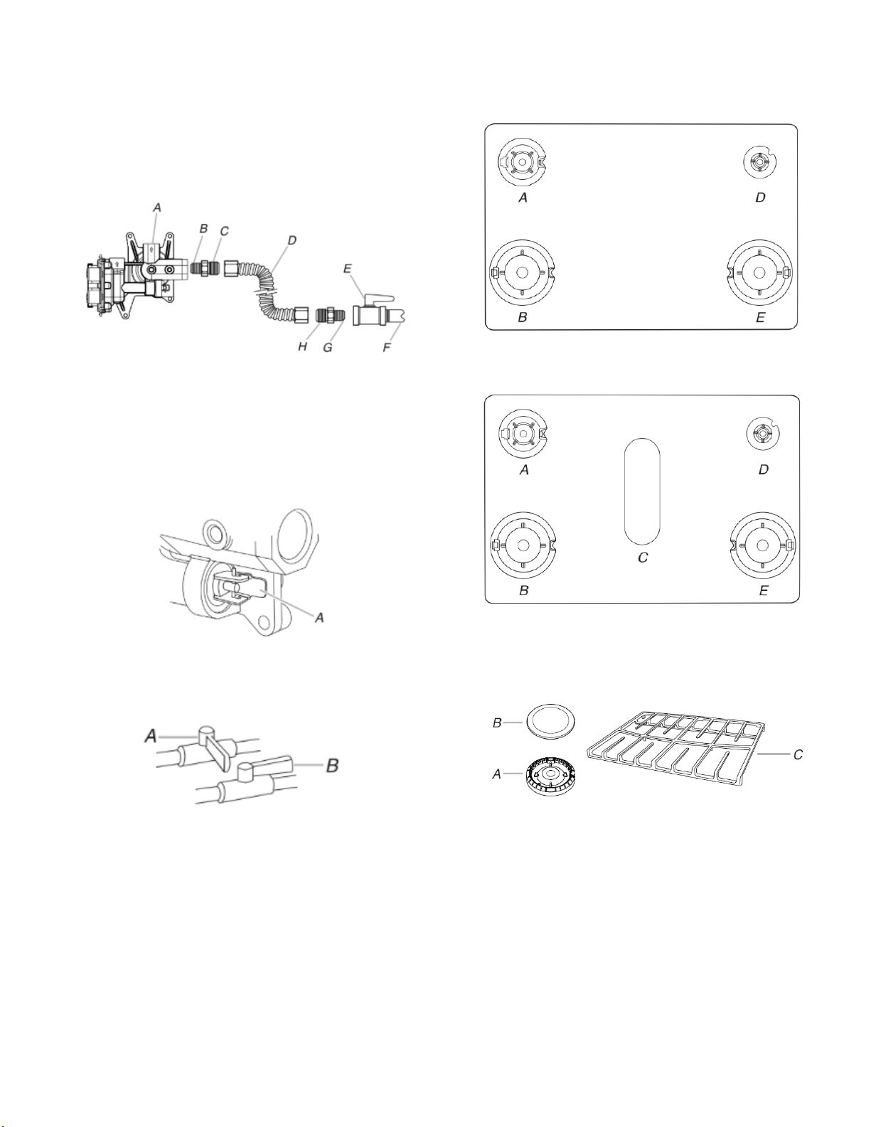
Typical flexible connection
1. Apply pipe-joint compound made for use with propane gas to
the smaller thread ends of the flexible connector adapters
(see B and G in the following illustration).
2. Attach one adapter to the gas pressure regulator and the other
adapter to the gas shut-off valve. Tighten both adapters.
3. Use a 15/16" (23.8 mm) combination wrench and channel lock
pliers to attach the flexible connector to the adapters. Check
that connector is not kinked.
A. Gas pressure regulator
B. Use pipe-joint compound.
C. Adapter (must have 1/3"
[12.7 mm] male pipe thread)
D. Flexible connector
E. Manual gas shutoff valve
F. 1/2" (12.7 mm) or 3/4"
(19.1 mm) gas pipe
G. Use pipe-joint compound.
H. Adapter
Complete Connection
1. Check that the gas pressure regulator shutoff valve is in the
“on” position.
A. Gas pressure regulator shut-off valve shown in
the “on” position
2. Open the manual shutoff valve in the gas supply line. The
valve is open when the handle is parallel to the gas pipe.
A. Closed valve
B. Open valve
3. Test all connections by brushing on an approved noncorrosive
leak-detection solution. If bubbles appear, a leak is indicated.
Correct any leak found.
4. Remove cooktop burner caps and bases from package
containing parts. Place the burner bases as indicated by the
following illustration for your model:
For model AGR6603SF :
A. Medium (Semi Rapid)
B. Large (Ultra Rapid)
D. Small (Auxiliary)
E. Large (Ultra Rapid)
For models MGR6600F and WFG550S0H:
A. Medium (Semi Rapid)
B. Large (Ultra Rapid)
C. Oval
D. Small (Auxiliary)
E. Large (Ultra Rapid)
5. Burner caps should be level when properly positioned. If
burner caps are not properly positioned, surface burners will
not light. Place burner grates over burners and caps.
A. Burner base
B. Burner cap
C. Burner grate
Loading ...
Loading ...
Loading ...