5F4012003B
Inglés 5F4012003B (06.12) (GT9)
LEON
Owner’s manual
LEON Inglés (06.12)

Foreword
This Instruction Manual and its corresponding supplements should be read carefully to familiarise yourself
with your vehicle.
Besides the regular care and maintenance of the vehicle, its correct handling will help preserve its value.
For safety reasons, always note the information concerning accessories, modifications and part replace-
ments.
If selling the vehicle, give all of the on-board documentation to the new owner, as it should be kept with the
vehicle.


Table of Contents
Manual structure . . . . . . . . . . . . . . . . . . . . 5
Content . . . . . . . . . . . . . . . . . . . . . . . . . . . . . . . . 6
Safety First . . . . . . . . . . . . . . . . . . . . . . . . . . . . 7
Safe driving . . . . . . . . . . . . . . . . . . . . . . . . . . . . . . . 7
Brief introduction . . . . . . . . . . . . . . . . . . . . . . . . . 7
Sitting position for vehicle occupants . . . . . . . . . 10
Pedal area . . . . . . . . . . . . . . . . . . . . . . . . . . . . . . . 16
Storing objects . . . . . . . . . . . . . . . . . . . . . . . . . . . 17
Seat belts . . . . . . . . . . . . . . . . . . . . . . . . . . . . . . . . . 19
Brief introduction . . . . . . . . . . . . . . . . . . . . . . . . . 19
Why wear seat belts? . . . . . . . . . . . . . . . . . . . . . . 21
Seat belts . . . . . . . . . . . . . . . . . . . . . . . . . . . . . . . 25
Seat belt tensioners . . . . . . . . . . . . . . . . . . . . . . . 28
Airbag system . . . . . . . . . . . . . . . . . . . . . . . . . . . . . 30
Brief introduction . . . . . . . . . . . . . . . . . . . . . . . . . 30
Front airbags . . . . . . . . . . . . . . . . . . . . . . . . . . . . . 35
Knee airbag* . . . . . . . . . . . . . . . . . . . . . . . . . . . . . 38
Side airbags* . . . . . . . . . . . . . . . . . . . . . . . . . . . . 39
Curtain airbags* . . . . . . . . . . . . . . . . . . . . . . . . . . 42
Deactivating airbags . . . . . . . . . . . . . . . . . . . . . . . 44
Child safety . . . . . . . . . . . . . . . . . . . . . . . . . . . . . . . 47
Brief introduction . . . . . . . . . . . . . . . . . . . . . . . . . 47
Child seats . . . . . . . . . . . . . . . . . . . . . . . . . . . . . . . 49
Securing child seats . . . . . . . . . . . . . . . . . . . . . . . 52
Operating instructions . . . . . . . . . . . . . 59
Controls and displays . . . . . . . . . . . . . . . . . . . . . . 59
Overview . . . . . . . . . . . . . . . . . . . . . . . . . . . . . . . . 58
Instruments and warning/control lamps . . . . 61
Instruments . . . . . . . . . . . . . . . . . . . . . . . . . . . . . . 61
Control lamps . . . . . . . . . . . . . . . . . . . . . . . . . . . . 69
Driver information system . . . . . . . . . . . . . . . . . . 73
Information system . . . . . . . . . . . . . . . . . . . . . . . . 73
Introduction to the Easy Connect system* . . . 79
System settings (CAR)* . . . . . . . . . . . . . . . . . . . . . 79
Opening and closing . . . . . . . . . . . . . . . . . . . . . . 86
Central locking system . . . . . . . . . . . . . . . . . . . . . 86
Anti-theft alarm system . . . . . . . . . . . . . . . . . . . . 93
Emergency locking and unlocking . . . . . . . . . . . . 96
Rear lid (luggage compartment) . . . . . . . . . . . . . 98
Electric windows . . . . . . . . . . . . . . . . . . . . . . . . . . 100
Panoramic sliding sunroof* . . . . . . . . . . . . . . . . . 103
Lights and visibility . . . . . . . . . . . . . . . . . . . . . . . . 106
Lights . . . . . . . . . . . . . . . . . . . . . . . . . . . . . . . . . . . 106
Sun blind . . . . . . . . . . . . . . . . . . . . . . . . . . . . . . . . 115
Windscreen wiper system . . . . . . . . . . . . . . . . . . . 116
Rear vision mirror . . . . . . . . . . . . . . . . . . . . . . . . . 122
Seats and storage . . . . . . . . . . . . . . . . . . . . . . . . . 125
General notes . . . . . . . . . . . . . . . . . . . . . . . . . . . . 125
Front seats . . . . . . . . . . . . . . . . . . . . . . . . . . . . . . . 125
Seat functions . . . . . . . . . . . . . . . . . . . . . . . . . . . . 126
Head restraints . . . . . . . . . . . . . . . . . . . . . . . . . . . 127
Storage . . . . . . . . . . . . . . . . . . . . . . . . . . . . . . . . . 129
Luggage compartment . . . . . . . . . . . . . . . . . . . . . 131
Air conditioning . . . . . . . . . . . . . . . . . . . . . . . . . . . 134
Heating, ventilation, cooling . . . . . . . . . . . . . . . . 134
Driving . . . . . . . . . . . . . . . . . . . . . . . . . . . . . . . . . . . . 143
Steering . . . . . . . . . . . . . . . . . . . . . . . . . . . . . . . . . 143
Ignition lock . . . . . . . . . . . . . . . . . . . . . . . . . . . . . . 144
Kick-down . . . . . . . . . . . . . . . . . . . . . . . . . . . . . . . 146
Handbrake . . . . . . . . . . . . . . . . . . . . . . . . . . . . . . . 147
Hill hold assist* . . . . . . . . . . . . . . . . . . . . . . . . . . . 148
Speed warning function . . . . . . . . . . . . . . . . . . . . 149
Start-Stop system* . . . . . . . . . . . . . . . . . . . . . . . . 149
Manual gearbox . . . . . . . . . . . . . . . . . . . . . . . . . . 152
Automatic gearbox/DSG automatic gearbox* . . . 154
Driver assistance systems . . . . . . . . . . . . . . . . . . 164
Cruise control system (CCS)* . . . . . . . . . . . . . . . . 164
Lane Assist system* . . . . . . . . . . . . . . . . . . . . . . . 168
SEAT Drive Modes* . . . . . . . . . . . . . . . . . . . . . . . . 171
Tiredness detection (break recommendation)* . 173
Tyre monitoring systems . . . . . . . . . . . . . . . . . . . . 175
Parking aid . . . . . . . . . . . . . . . . . . . . . . . . . . . . . . 178
Practical Tips . . . . . . . . . . . . . . . . . . . . . . . . . 183
Intelligent technology . . . . . . . . . . . . . . . . . . . . . 183
Electronic Stability Control (ESC) . . . . . . . . . . . . . 183
Brakes . . . . . . . . . . . . . . . . . . . . . . . . . . . . . . . . . . 185
Electro-mechanical steering . . . . . . . . . . . . . . . . . 186
Power Management . . . . . . . . . . . . . . . . . . . . . . . 187
Information recorded in the control units . . . . . . 189
Driving and the environment . . . . . . . . . . . . . . . 190
Running in the engine . . . . . . . . . . . . . . . . . . . . . 190
Driving through flooded roads . . . . . . . . . . . . . . . 190
Installation of exhaust gas filtration systems . . . 190
Economic and ecological driving . . . . . . . . . . . . . 191
Environmental friendliness . . . . . . . . . . . . . . . . . 192
3Table of Contents

Trailer . . . . . . . . . . . . . . . . . . . . . . . . . . . . . . . . . . . . . 194
Trailer towing . . . . . . . . . . . . . . . . . . . . . . . . . . . . . 194
Retrofitting a towing bracket* . . . . . . . . . . . . . . . 196
Care and cleaning . . . . . . . . . . . . . . . . . . . . . . . . . 198
General information . . . . . . . . . . . . . . . . . . . . . . . 198
Care of vehicle exterior . . . . . . . . . . . . . . . . . . . . . 198
Care of the vehicle interior . . . . . . . . . . . . . . . . . . 202
Checking and refilling levels . . . . . . . . . . . . . . . 206
Fuel . . . . . . . . . . . . . . . . . . . . . . . . . . . . . . . . . . . . 206
Filling the tank . . . . . . . . . . . . . . . . . . . . . . . . . . . . 207
Bonnet . . . . . . . . . . . . . . . . . . . . . . . . . . . . . . . . . . 209
Engine oil . . . . . . . . . . . . . . . . . . . . . . . . . . . . . . . . 211
Cooling system . . . . . . . . . . . . . . . . . . . . . . . . . . . 215
Brake fluid . . . . . . . . . . . . . . . . . . . . . . . . . . . . . . . 217
Battery . . . . . . . . . . . . . . . . . . . . . . . . . . . . . . . . . . 217
Windscreen washer reservoir and wiper blades . 220
Wheels and tyres . . . . . . . . . . . . . . . . . . . . . . . . . . 223
Wheels . . . . . . . . . . . . . . . . . . . . . . . . . . . . . . . . . . 223
Accessories and modifications to the vehicle 230
Accessories, replacement parts and repairs . . . . 230
Technical modifications . . . . . . . . . . . . . . . . . . . . 230
Radio transmitters and business equipment . . . 230
Emergencies . . . . . . . . . . . . . . . . . . . . . . . . . . . . . . 232
General information . . . . . . . . . . . . . . . . . . . . . . . 232
Equipment . . . . . . . . . . . . . . . . . . . . . . . . . . . . . . . 232
Tyre repair kit . . . . . . . . . . . . . . . . . . . . . . . . . . . . . 233
Changing a wheel . . . . . . . . . . . . . . . . . . . . . . . . . 235
Spare wheel . . . . . . . . . . . . . . . . . . . . . . . . . . . . . . 240
Jump starting . . . . . . . . . . . . . . . . . . . . . . . . . . . . . 241
Towing and tow-starting the vehicle . . . . . . . . . . 244
Fuses and bulbs . . . . . . . . . . . . . . . . . . . . . . . . . . . 249
Electrical fuses . . . . . . . . . . . . . . . . . . . . . . . . . . . 249
Bulbs . . . . . . . . . . . . . . . . . . . . . . . . . . . . . . . . . . . 252
Changing bulbs in headlight unit . . . . . . . . . . . . 254
Changing bulb for front fog light . . . . . . . . . . . . . 256
Changing tail light bulbs (on side panel) . . . . . . 257
Changing tail light bulbs (on rear lid) . . . . . . . . . 259
Changing number plate light bulbs . . . . . . . . . . . 261
Technical specifications . . . . . . . . . . . . 263
Technical specifications . . . . . . . . . . . . . . . . . . . . 263
Important . . . . . . . . . . . . . . . . . . . . . . . . . . . . . . . . 263
Vehicle identification data . . . . . . . . . . . . . . . . . . 264
Information on fuel consumption . . . . . . . . . . . . 265
Towing a trailer . . . . . . . . . . . . . . . . . . . . . . . . . . . 265
Wheels . . . . . . . . . . . . . . . . . . . . . . . . . . . . . . . . . . 266
Engine specifications . . . . . . . . . . . . . . . . . . . . . . 267
Dimensions and capacities . . . . . . . . . . . . . . . . . 276
Index . . . . . . . . . . . . . . . . . . . . . . . . . . . . . . . . . . . 277
4 Table of Contents
5Manual structure
Manual structure
What you should know before reading this manual
This manual contains a description of the equipment supplied with the ve-
hicle at the time of press. Some of the equipment hereunder described will
not be available until a later date, or is only available in certain markets.
Because this is a general manual for the LEON, some of the equipment and
functions that are described in this manual are not included in all types or
variants of the model or model year; they may vary or be modified in ac-
cordance with technical or market requirements or model year; this can not
be interpreted as dishonest advertising.
The illustrations are intended as a general guide and may vary from the
equipment fitted in your vehicle in some details.
The direction indications (left, right, front, rear) appearing in this manual re-
fer to the normal forward working direction of the vehicle except when oth-
erwise indicated.
The equipment marked with an asterisk** is fitted as standard only in cer-
tain versions, and is only supplied as optional extras for some versions, or
are only offered in certain countries.
All registered marks are indicated with ®. Although the copyright sym-
bol does not appear, it is a copyrighted mark.
The section is continued on the following page.
Marks the end of a section.
WARNING
Texts preceded by this symbol contain information on safety. They warn
you about possible dangers of accident or injury.
®
CAUTION
Texts with this symbol draw your attention to potential sources of damage
to your vehicle.
For the sake of the environment
Texts preceded by this symbol contain relevant information concerning envi-
ronmental protection.
Note
Texts preceded by this symbol contain additional information.

6 Content
Content
This manual is structured to provide the information you need in an organ-
ised way. The content of this Manual is divided into sections which belong
to chapters (e.g. “Air conditioning”). The entire manual is divided into five
large parts which are:
1. Safety First
Information about the vehicle equipment relating to passive safety such as
seat belts, airbags, seats, etc.
2. Operating instructions
Information about the distribution of controls in the driver position of your
vehicle, about the seat adjustment possibilities, about how to create a suit-
able climate in the vehicle interior, etc.
3. Practical Tips
Advice relating to the driving, caring and maintenance of your vehicle and
certain problems you can solve yourself.
4. Technical specifications
Figures, values and the dimensions of your vehicle.
5. Alphabetic index
At the end of this manual there is a detailed alphabetical index, this will
help you to quickly find the information you require.
7Safe driving
Safety First
Safe driving
Brief introduction
Dear SEAT Driver
Safety first!
This chapter contains important information, tips, suggestions and
warnings that you should read and consider for both your own
safety and for your passengers' safety.
WARNING
● This manual contains important information about the operation of
the vehicle, both for the driver and the passengers. The other sections of
the on-board documentation also contain further information that you
should be aware of for your own safety and for the safety of your passen-
gers.
● Ensure that the on-board documentation is kept in the vehicle at all
times. This is especially important when lending or selling the vehicle to
another person.
Safety equipment
The safety equipment is a part of the occupant protection
system and can reduce the risk of injury in the event of acci-
dent.
Never put your safety or the safety of your passengers in danger. In the
event of an accident, the safety equipment may reduce the risk of injury.
The following list includes most of the safety equipment in your SEAT:
● Three-point seat belts
● Belt tension limiters for the front and rear side seats
● Belt tensioners for the front seats
● Front airbags
● knee airbags,
● Side airbags in the front seat backrests
● Side airbags in the rear seat backrests*
● Curtain airbags
● ISOFIX anchor points for child seats in the rear side seats with the ISOFIX
system,
● Height-adjustable front head restraints
● Rear head restraints with in-use position and non-use position
● Adjustable steering column
The safety equipment mentioned above works together to provide you and
your passengers with the best possible protection in the event of an acci-
dent. However, these safety systems can only be effective if you and your
Safety First Operating instructions Practical Tips Technical specifications

8 Safe driving
passengers are sitting in a correct position and use this equipment proper-
ly.
Therefore, information is provided about why this equipment is so impor-
tant, how it protects you, what you have to consider when using it and how
you and your passengers can achieve the greatest possible benefit from the
safety equipment fitted. This manual includes important warnings that you
and your passengers should note in order to reduce the risk of injury.
Safety is everyone's business!
Before starting every trip
The driver is always responsible for the safety of the passen-
gers and the safe operation of the vehicle.
For your own safety and the safety of your passengers, always note
the following points before every trip:
– Make sure that the vehicle's lights and turn signals are working
properly.
– Check tyre pressure.
– Ensure that all windows provide a clear and good view of the
surroundings.
– Make sure all luggage is secured ⇒ page 17.
– Make sure that no objects can interfere with the pedals.
– Adjust front seat, head restraint and rear vision mirrors properly
according to your size.
– Ensure that the passengers in the rear seats always have the
head restraints in the in-use position ⇒ page 15
– Instruct passengers to adjust the head restraints according to
their height.
– Protect children with appropriate child seats and properly ap-
plied seat belts ⇒ page 47.
– Assume the correct sitting position. Instruct your passengers al-
so to assume a proper sitting position. ⇒ page 10.
– Fasten your seat belt securely. Instruct your passengers also to
fasten their seat belts properly. ⇒ page 19.
What affects driving safety?
Driving safety is largely determined by your driving style
and the personal behaviour of all vehicle occupants.
As a driver, you are responsible for yourself and your passengers.
When your concentration or driving safety is affected by any cir-
cumstance, you endanger yourself as well as others on the road
⇒
, for this reason:
– Always pay attention to traffic and do not get distracted by pas-
sengers or telephone calls.
– Never drive when your driving ability is impaired (e.g. by medi-
cation, alcohol, drugs).
– Observe traffic laws and speed limits.
9Safe driving
– Always reduce your speed as appropriate for road, traffic and
weather conditions.
– When travelling long distances, take breaks regularly - at least
every two hours.
– If possible, avoid driving when you are tired or stressed.
WARNING
When driving safety is impaired during a trip, the risk of injury and acci-
dents increases.
Safety First Operating instructions Practical Tips Technical specifications
10 Safe driving
Sitting position for vehicle occupants
Introduction
WARNING
● The front seats, head restraints and seat belts must always be adjus-
ted to the size of the vehicle occupant to provide you and your passen-
gers with the greatest possible protection.
● Ensure your correct sitting position before setting off, and do not
change this during the journey. Also advise your passengers to ensure
their correct sitting positions not to be changed.
● A vehicle occupant sitting in an incorrect position is at risk of serious
injury in the event that an airbag is activated.
● If the passengers in the rear seats are not sitting in an upright posi-
tion, they are more likely to be injured due to the incorrect position of the
seat belts.
● It is important that the driver keeps at a minimum of 25 cm from the
steering wheel. It is important that the passenger keeps at a minimum of
25 cm from the dash panel. The airbag system will not be able to give the
required protection if the minimum distance is not observed. This can
cause a risk of fatal injury!
● When driving, always hold the steering wheel with both hands on the
outside part at the 9 o'clock and 3 o'clock positions. Never hold the
steering wheel at the 12 o'clock position, or in any other manner (e.g. in
the centre of the steering wheel or along its interior edge). In such cases,
if the airbag is triggered, you may sustain injuries to the arms, hands
and head.
● The backrests must not be reclined too far back while driving. This
could limit the effect of the seat belts and the airbag system. Risk of in-
jury!
WARNING (Continued)
● Objects must not be placed in the footwell, as they could move to the
area of the pedals in the event of a braking manoeuvre or change of direc-
tion. This would prevent the clutch, brake or accelerator from being
pressed.
● Always keep your feet on the footwell when the vehicle is moving;
never rest them on the dash panel, on the window or on the seat! An in-
correct sitting position exposes you to an increased risk of injury in case
of a sudden braking or an accident. If the airbag is triggered, you could
sustain severe injuries due to an incorrect sitting position!
11Safe driving
Correct sitting position for driver
The correct sitting position for the driver is important for
safe and relaxed driving.
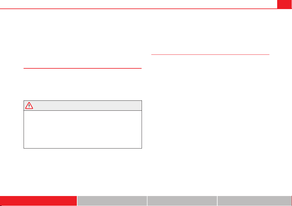
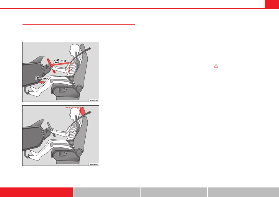
Fig. 1 The correct dis-
tance between driver and
steering wheel
Fig. 2 Correct head re-
straint position for driver
For your own safety and to reduce the risk of injury in the event of
an accident, we recommend the following adjustments for the driv-
er:
– Adjust the steering wheel so that there is a distance of at least
25 cm between the steering wheel and the centre of your chest
⇒ Fig. 1.
– Move the driver seat forwards or backwards so that you are able
to press the accelerator, brake and clutch pedals to the floor
with your knees still slightly angled ⇒
.
– Ensure that you can reach the highest point of the steering
wheel.
– Adjust the head restraint so that its upper edge is at the same
level as the top of your head, or as close as possible to the
same level as the top of your head ⇒ Fig. 2.
– Move the seat backrest to an upright position so that your back
rests completely against it.
– Fasten your seat belt securely ⇒ page 19.
– Keep both feet in the footwell so that you have the vehicle un-
der control at all times.
Adjustment of the driver seat ⇒ page 125.
Safety First Operating instructions Practical Tips Technical specifications
12 Safe driving
WARNING
● An incorrect sitting position of the driver can lead to severe injuries.
● Adjust the driver seat so that there is at least 25 cm distance between
the centre of the chest and the centre of the steering wheel ⇒ Fig. 1. If
you are sitting closer than 25 cm, the airbag system cannot protect you
properly.
● If your physical constitution prevents you from maintaining the mini-
mum distance of 25 cm, contact a specialised workshop. The workshop
will help you decide if special specific modifications are necessary.
● When driving, always hold the steering wheel with both hands on the
outside of the ring at the 9 o'clock and 3 o'clock positions. This reduces
the risk of injury when the driver airbag is triggered.
● Never hold the steering wheel at the 12 o'clock position, or in any
other manner (e.g. in the centre of the steering wheel). In such cases, if
the airbag is triggered, you may sustain injuries to the arms, hands and
head.
● To reduce the risk of injury to the driver during sudden braking ma-
noeuvres or an accident, never drive with the backrest tilted far back! The
airbag system and seat belts can only provide optimal protection when
the backrest is in an upright position and the driver is wearing his or her
seat belt correctly. The further the seat backrests are tilted to the rear,
the greater the risk of injury due to incorrect positioning of the belt web
or to the incorrect sitting position!
● Adjust the head restraint properly to achieve optimal protection.
Correct sitting position for front passenger
The front passenger must sit at least 25 cm away from the
dash panel so that the airbag can provide the greatest pos-
sible protection in the event that it is triggered.
For your own safety and to reduce the risk of injury in the event of
an accident, we recommend the following adjustments for the front
passenger:
– Move the front passenger seat back as far as possible ⇒
.
– Move the seat backrest to an upright position so that your back
rests completely against it.
– Adjust the head restraint so that its upper edge is at the same
level as the top of your head, or as close as possible to the
same level as the top of your head ⇒ page 14.
– Always keep both feet in the footwell in front of the front pas-
senger seat.
– Fasten your seat belt securely ⇒ page 19.
It is possible to deactivate the front passenger airbag in exceptional circum-
stances ⇒ page 26.
Adjusting the front passenger seat ⇒ page 125.
13Safe driving
WARNING
● An incorrect sitting position of the front passenger can lead to severe
injuries.
● Adjust the front passenger seat so that there is at least 25 cm be-
tween your chest and the dash panel. If you are sitting closer than 25 cm,
the airbag system cannot protect you properly.
● If your physical constitution prevents you from maintaining the mini-
mum distance of 25 cm, contact a specialised workshop. The workshop
will help you decide if special specific modifications are necessary.
● Always keep your feet in the footwell when the vehicle is moving;
never rest them on the dash panel, out the window or on the seat. An in-
correct sitting position exposes you to an increased risk of injury in case
of a sudden braking or an accident. If the airbag is triggered, you could
sustain severe injuries due to an incorrect sitting position.
● To reduce the risk of injury to the front passenger in events such as
sudden braking manoeuvres or an accident, never travel with the back-
rest tilted far back! The airbag system and seat belts can only provide op-
timal protection when the backrest is in an upright position and the front
passenger is wearing his or her seat belt properly. The further the seat
backrests are tilted to the rear, the greater the risk of injury due to incor-
rect positioning of the belt web or to the incorrect sitting position!
● Adjust the head restraint correctly in order to achieve maximum pro-
tection.
Correct sitting position for passengers in the rear seats
Passengers in the rear seats must sit up straight, keep their
feet in the footwells, have the head restraints positioned for
use and wear their seat belts properly.
To reduce the risk of injury in the event of a sudden braking ma-
noeuvre or an accident, passengers on the rear seat bench must
consider the following:
– Adjust the head restraint to the correct position. ⇒ page 15
– Always keep both feet in the footwell in front of the rear seat.
– Fasten your seat belt securely ⇒ page 19.
– Use an appropriate child restraint system when you take chil-
dren in the vehicle ⇒ page 47.
WARNING
● If the passengers in the rear seats are not sitting properly, they could
sustain severe injuries.
● Adjust the head restraint correctly in order to achieve maximum pro-
tection.
● Seat belts can only provide optimal protection when seat backrests
are in an upright position and the vehicle occupants are wearing their
seat belts correctly. If passengers In the rear seats are not sitting in an
upright position, the risk of injury due to incorrect positioning of the seat
belt increases.
Safety First Operating instructions Practical Tips Technical specifications
14 Safe driving
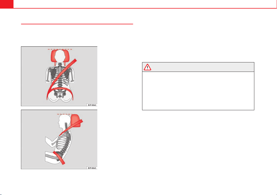
Correct adjustment of front seat head restraints
Properly adjusted head restraints are an important part of
passenger protection and can reduce the risk of injuries in
most accident situations.
Fig. 3 Correctly adjusted
head restraint viewed
from the front
Fig. 4 Correctly adjusted
head restraint viewed
from the side
Adjust the head restraint correctly in order to achieve maximum
protection.
– Adjust the head restraint so that its upper edge is at the same
level as the top of your head, or as close as possible to the
same level as the top of your head and, at the very least, at eye
level. ⇒ Fig. 3 and ⇒ Fig. 4.
Adjusting the head restraints ⇒ page 127
WARNING
● Travelling with the head restraints removed or improperly adjusted
increases the risk of severe injuries.
● Incorrectly adjusted head restraints could result in death in the event
of a collision or accident.
● Incorrectly adjusted head restraints also increase the risk of injury
during sudden or unexpected driving or braking manoeuvres.
● The head restraints must always be adjusted according to the height
of the passenger.
15Safe driving
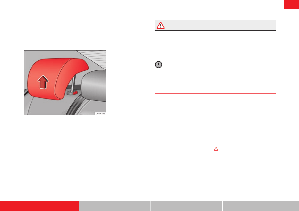
Correct adjustment of rear seat head restraints
Properly adjusted head restraints are an important part of
the passenger protection and can reduce the risk of injuries
in most accident situations
Fig. 5 Head restraints in
correct position
Rear head restraints
– The rear head restraints have 2 positions: use and non-use.
– One position for use (head restraint raised) ⇒ Fig. 5. In this po-
sition, the head restraints are used normally, protecting pas-
sengers along with the rear seat belts.
– And one position for non-use (head restraint lowered).
– To fit the head restraints in position for use, pull on the edges
with both hands in the direction of the arrow.
WARNING
● Under no circumstances should the rear passengers travel while the
head restraints are in the non-use position.
● Do not swap the centre rear head restraint with either of the outer
seat rear head restraints.
● Risk of injury in case of an accident!
CAUTION
Note the instructions on the adjustment of the head restraints ⇒ page 127.
Examples of incorrect sitting positions
An incorrect sitting position can lead to severe injuries to ve-
hicle occupants.
Seat belts can provide optimal protection only when the belt webs
are properly positioned. Incorrect sitting positions substantially re-
duce the protective function of seat belts and increase the risk of
injury due to incorrect seat belt position. As the driver, you are re-
sponsible for all passengers, especially children.
– Never allow anyone to assume an incorrect sitting position in
the vehicle while travelling
⇒
.
The following list contains examples of sitting positions that could be dan-
gerous for all vehicle occupants. The list is not complete, but we would like
to make you aware of this issue.
Therefore, whenever the vehicle is in motion:
● Never stand in the vehicle.
● Never stand on the seats.
Safety First Operating instructions Practical Tips Technical specifications
16 Safe driving
● Never kneel on the seats.
● Never tilt your seat backrest far to the rear.
● Never lean against the dash panel.
● Never lie on the rear bench.
● Never sit on the front edge of a seat.
● Never sit sideways.
● Never lean out of a window.
● Never put your feet out of a window.
● Never put your feet on the dash panel.
● Never put your feet on the surface of a seat.
● Do not allow anyone to travel in the footwell.
● Never travel without wearing the seat belt.
● Do not allow anyone to travel in the luggage compartment.
WARNING
● Any incorrect sitting position increases the risk of severe injuries.
● Sitting in an incorrect position exposes the vehicle occupants to se-
vere injuries if airbags are triggered, by striking a vehicle occupant who
has assumed an incorrect sitting position.
● Before the vehicle moves, assume the proper sitting position and
maintain it throughout the trip. Before every trip, instruct your passen-
gers to sit properly and to stay in this position during the trip ⇒ page 10,
Sitting position for vehicle occupants.
Pedal area
Pedals
The operation of all pedals must never be impaired by ob-
jects or floor mats.
– Ensure that you can always press the accelerator, brake and
clutch pedals unimpaired to the floor.
– Ensure that the pedals can return unimpaired to their initial po-
sitions.
Use only floor mats which leave the pedal area free and can be securely fas-
tened on the footwell.
If a brake circuit fails, the brake pedal must be pressed down thoroughly in
order to stop the vehicle.
Wearing suitable shoes
Always wear shoes which support your feet properly and give you a good
feeling for the pedals.
WARNING
● Restricting pedal operation can lead to critical situations while driv-
ing.
● Never place objects on the driver footwell. An object could move into
the pedal area and impair pedal operation. In the event of a sudden driv-
ing or braking manoeuvre, you will not be able to operate the brake,
clutch or accelerator pedal. Risk of accident!
17Safe driving
Floor mats on the driver side
Only floor mats may be used which can be securely fastened
in the footwell and do not impair operation of the pedals.
– Ensure that the floor mats are securely fastened during the trip
and do not obstruct the pedals ⇒
.
Only use floor mats which leave the pedals clear and which are secured to
prevent them from slipping. You can obtain suitable floor mats from a speci-
alised dealership. Fasteners* for floor mats are fitted in the footwells.
WARNING
● If the pedals are obstructed, an accident may occur. Risk of serious
injuries.
● Ensure that the floor mats are always securely attached.
● Never lay or fit floor mats or other floor coverings over the original
floor mats. This would reduce the pedal area and could obstruct the ped-
als. Risk of accident.
Storing objects
Loading the luggage compartment
All luggage and other loose objects must be safely secured
in the luggage compartment.
Unsecured objects which shift back and forth could impair the driv-
ing safety or driving characteristics of the vehicle by shifting the
centre of gravity.
– Distribute the load evenly in the luggage compartment.
– Place heavy objects as far forward as possible in the luggage
compartment.
– Place the heavy objects first.
– Secure heavy objects to the fitted fastening rings ⇒ page 18.
WARNING
● Loose luggage and other objects in the luggage compartment could
cause serious injuries.
● Always stow objects in the luggage compartment and secure them on
the fastening rings.
● Use suitable straps to secure heavy objects.
● During sudden manoeuvres or accidents, loose objects can be thrown
forward, injuring vehicle occupants or passers-by. This increased risk of
injury will be further increased if a loose object is struck by an inflating
airbag. If this happens, objects can be transformed into “missiles”. Risk
of fatal injury.
● Please note that the centre of gravity may shift when transporting
heavy objects; this may affect vehicle handling and lead to an accident.
Therefore, it is essential to adjust your speed and driving style accord-
ingly, to avoid accidents.
● Never exceed the allowed axle weights or allowed maximum weight.
If the allowed axle load or the allowed total weight is exceeded, the driv-
ing characteristics of the vehicle may change, leading to accidents, inju-
ries and damage to the vehicle.
● Never leave your vehicle unattended, especially when the rear lid is
open. Children could climb into the luggage compartment, closing the
door behind them; they will be trapped and run the risk of death.
Safety First Operating instructions Practical Tips Technical specifications
18 Safe driving
WARNING (Continued)
● Never allow children to play in or around the vehicle. Close and lock
all the doors and rear lid when you leave the vehicle. Before you lock the
vehicle, make sure that there are no adults or children in the vehicle.
● Never transport passengers in the luggage compartment. All vehicle
occupants must have their seat belt fastened ⇒ page 19.
Note
● Air circulation in the vehicle helps reduce fogging of the windows. Used
air escapes through ventilation slits in the side trim of the luggage compart-
ment. Ensure that the ventilation slits are never covered.
● Straps for securing the load to the fastening rings are commercially
available.
Fastening rings*
There can be four fastening rings in the luggage compart-
ment for fastening luggage and other objects.
– Always use suitable and undamaged straps to secure luggage
and other objects to the fastening rings ⇒
in Loading the lug-
gage compartment on page 17.
Bear in mind that in the case of a collision or accident, even small and light
objects that are not firmly fixed can be projected at the occupants causing
injury.
Example: An object weighing 4.5 kg is lying unsecured in the vehicle. Dur-
ing a frontal collision at a speed of 50 km/h (30 mph), this object generates
a force corresponding to 20 times its weight. That means that the effective
weight of the object increases to about 90 kg. You can imagine the severity
of the injuries which might be sustained if this object strikes an occupant as
it flies through the interior of the vehicle. This increased risk of injury will be
further increased if a loose object is struck by an inflating airbag.
WARNING
● If pieces of luggage or other objects are secured to the fastening
rings with inappropriate or damaged retaining cords, injuries could be
sustained in the event of braking manoeuvres or accidents.
● To prevent pieces of luggage or other objects from flying forward, al-
ways use appropriate retaining cords which are secured to the fastening
rings.
● Never secure a child seat on the fastening rings.
19Seat belts
Seat belts
Brief introduction
Before driving: remember your seat belt!
Wearing a seat belt properly can save your life!
In this section you will learn the importance of wearing seat belts,
how they work and how to properly fasten, adjust and wear them.
– Read and consider all the information as well as the warnings in
this chapter.
WARNING
● If seat belts are worn incorrectly or not at all, the risk of severe inju-
ries increases.
● Properly worn seat belts can reduce severe injuries in case of sudden
braking manoeuvres or accidents. For safety reasons, you and all other
vehicle occupants must always wear the seat belts properly while the ve-
hicle is moving.
● Pregnant women or people with physical disabilities must also use
seat belts. Like all other vehicle occupants, these people can also sustain
severe injuries if they are not wearing their seat belts properly.
Number of seats
Your vehicle has five seats, two in the front and three in the rear. Each seat
is equipped with a three-point seat belt.
In some versions, your vehicle is approved only for four seats. Two front
seats and two rear seats.
WARNING
● Never transport more than the permitted amount of people in your ve-
hicle.
● Every vehicle occupant must properly fasten and wear the seat belt
belonging to his or her seat. Children must be protected with an appro-
priate child restraint system.
Seat belt warning lamp*
The control lamp acts as a reminder to the driver to fasten
the seat belt.
Before starting the vehicle:
– Fasten your seat belt securely.
– Instruct your passengers to fasten their seat belts properly be-
fore driving off.
– Protect children by using a child seat according to the child's
height and weight.
Safety First Operating instructions Practical Tips Technical specifications

20 Seat belts
After the ignition has been switched on, the control lamp on the instru-
ment panel lights up
1)
if the driver has not fastened his/her seat belt, and
an audible warning is heard if the vehicle is driven at more than 30 km/h
(20 mph).
The warning lamp* is switched off if the driver seat belt is fastened while
the ignition is switched on.
1)
Depending on the model version
21Seat belts
Why wear seat belts?
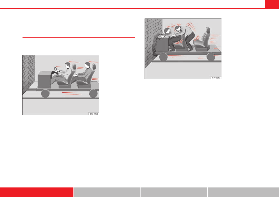
Physical principles of frontal collisions
In the event of a frontal collision, a large amount of kinetic
energy must be absorbed.
Fig. 6 Vehicle about to
hit a wall: the occupants
are not wearing seat
belts
Fig. 7 The vehicle hits
the wall: the occupants
are not wearing seat
belts
It is easy to explain how the laws of physics work in the case of a head-on
collision: When a vehicle starts moving
⇒
Fig. 6, a certain amount of energy
known as kinetic energy is produced in the vehicle and its occupants.
The amount of kinetic energy depends on the speed of the vehicle and the
weight of the vehicle and its passengers. The higher the speed and the
greater the weight, the more energy there is to be released in an accident.
The most significant factor, however, is the speed of the vehicle. If the
speed doubles from 25 km/h (15 mph) to 50 km/h (30 mph), for example,
the kinetic energy is multiplied by four.
Because the vehicle occupants in our example are not restrained by seat
belts, all of the occupants' kinetic energy has to be absorbed at the point of
impact
⇒
Fig. 7.
Even at speeds of 30 km/h (20 mph) to 50 km/h (30 mph), the forces acting
on bodies in a collision can easily exceed one tonne (1000 kg). At greater
speed these forces are even higher.
Safety First Operating instructions Practical Tips Technical specifications
22 Seat belts
Vehicle occupants not wearing seat belts are not “attached” to the vehicle.
In a head-on collision, they will move forward at the same speed their vehi-
cle was travelling just before the impact. This example applies not only to
head-on collisions, but to all accidents and collisions.
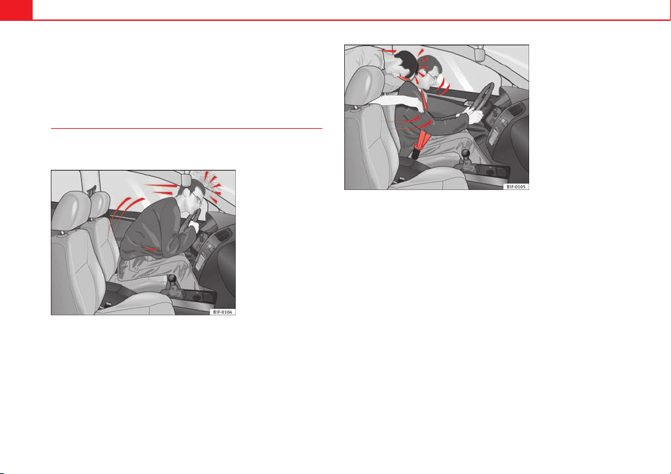
The danger of not using the seat belt
The general belief that the passengers can protect them-
selves with their hands in a minor collision is false.
Fig. 8 A driver not wear-
ing a seat belt is thrown
forward violently
Fig. 9 The unbelted pas-
senger in the rear seat is
thrown forward violently,
hitting the driver wearing
a seat belt
Even at low speeds the forces acting on the body in a collision are so great
that it is not possible to brace oneself with one's hands. In a frontal colli-
sion, unbelted vehicle occupants are thrown forward and will make violent
contact with the steering wheel, dash panel, windscreen or whatever else is
in the way
⇒
Fig. 8.
The airbag system is not a substitute for seat belts. When triggered, airbags
provide only additional protection. All occupants (including the driver) must
wear seat belts properly at all times during the trip. This will reduce the risk
of severe injuries in the event of an accident – regardless of whether an air-
bag is fitted for the seat or not.
Note that airbags can be triggered only once. To achieve the best possible
protection, the seat belt must always be worn properly so that you will be
protected in accidents in which no airbag is deployed.
It is also important for the rear passengers to wear seat belts properly, as
they could otherwise be thrown forward violently through the vehicle interi-
or in an accident. Passengers in the rear seats who do not use seat belts
endanger not only themselves but also the front occupants
⇒
Fig. 9.
23Seat belts
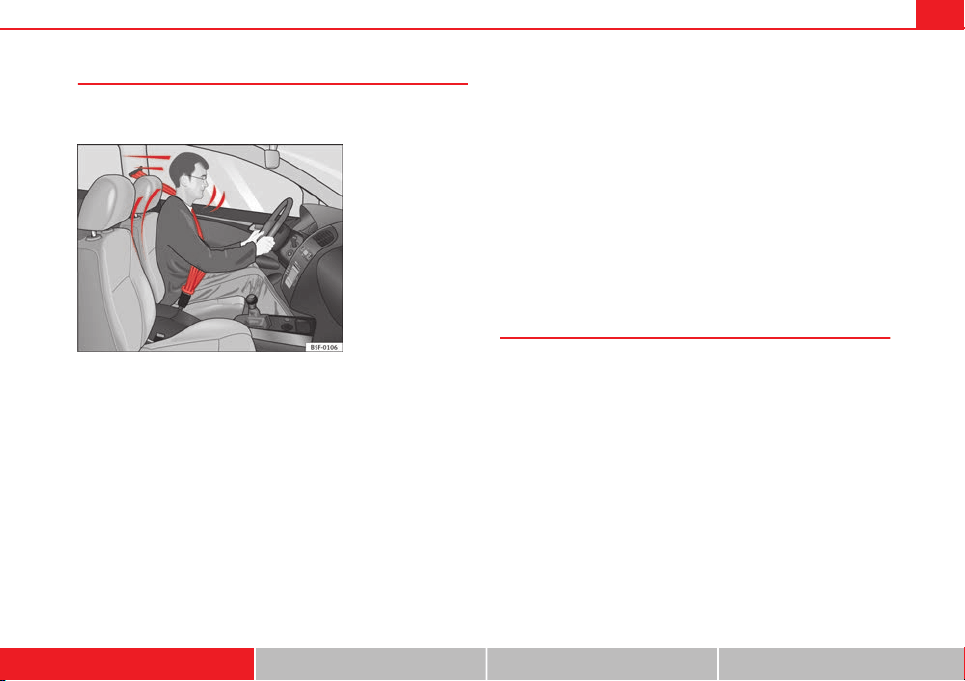
Seat belt protection
Passengers not wearing seat belts risk severe injuries in the
event of an accident.
Fig. 10 A driver wearing
the seat belt properly is
secured by the belt in
sharp braking
Properly worn seat belts hold the vehicle occupants in the correct sitting po-
sitions and substantially reduce the kinetic energy in the event of an acci-
dent. Seat belts also help to prevent uncontrolled movements that could
lead to severe injuries. In addition, properly worn seat belts reduce the dan-
ger of being thrown from the vehicle.
Vehicle occupants wearing their seat belts correctly benefit greatly from the
ability of the belts to absorb kinetic energy. The front part of your vehicle
and other passive safety features (such as the airbag system) are also de-
signed to absorb the kinetic energy released in a collision. Taken together,
all these features reduce the releasing kinetic energy and consequently, the
risk of injury.
Our examples describe frontal collisions. Of course, properly worn seat belts
substantially reduce the risk of injury in all other types of accidents. This is
why it is so important to fasten seat belts before every trip, even when "just
driving around the corner".
Ensure that your passengers wear their seat belts as well. Accident statistics
have shown that wearing seat belts is an effective means of substantially
reducing the risk of injury and improving the chances of survival in a seri-
ous accident. Furthermore, properly worn seat belts improve the protection
provided by airbags in the event of an accident. For this reason, wearing a
seat belt is required by law in most countries.
Although your vehicle is equipped with airbags, the seat belts must be fas-
tened and worn. The front airbags, for example, are only triggered in some
frontal accidents. The front airbags will not be triggered during minor frontal
collisions, minor side collisions, rear collisions, overturns or accidents in
which the airbag trigger threshold value in the control unit is not exceeded.
Therefore, you should always wear your seat belt and ensure that all vehicle
occupants have fastened their seat belts properly before you drive off!
Safety instructions on using seat belts
If seat belts are used correctly, they can considerably reduce
the risk of injury in an accident.
– Always wear the seat belt as described in this section.
– Ensure that the seat belts can be fastened at all times and are
not damaged.
Safety First Operating instructions Practical Tips Technical specifications
24 Seat belts
WARNING
● If the seat belts are worn incorrectly or not at all, the risk of severe
injuries increases. The optimal protection from seat belts can be ach-
ieved only if you use them properly.
● Fasten your seat belt before every trip - even when driving in town.
The other vehicle occupants must also wear the seat belts at all times,
otherwise they run the risk of being injured.
● The seat belt cannot offer its full protection if the seat belt is not
positioned correctly.
● Never allow two passengers (even children) to share the same seat
belt.
● Always keep both feet in the footwell in front of your seat as long as
the vehicle is in motion.
● Never unbuckle a seat belt while the vehicle is in motion. Risk of fatal
injury.
● The seat belt must never be twisted while it is being worn.
● The seat belt should never lie on hard or fragile objects (such as
glasses or pens, etc.) because this can cause injuries.
● Do not allow the seat belt to be damaged or jammed, or to rub on any
sharp edges.
● Never wear the seat belt under the arm or in any other incorrect posi-
tion.
● Loose, bulky clothing (such as an overcoat over a jacket) impairs the
proper fit and function of the seat belts, reducing their capacity to pro-
tect.
● The slot in the seat belt buckle must not be blocked with paper or
other objects, as this can prevent the latch plate from engaging securely.
● Never use seat belt clips, fastening rings or similar instruments to al-
ter the position of the belt webbing.
WARNING (Continued)
● Frayed or torn seat belts or damage to the connections, belt retrac-
tors or parts of the buckle could cause severe injuries in the event of an
accident. Therefore, you must check the condition of all seat belts at reg-
ular intervals.
● Seat belts which have been worn in an accident and stretched must
be replaced by a specialised workshop. Renewal may be necessary even
if there is no apparent damage. The belt anchorage should also be
checked.
● Do not attempt to repair a damaged seat belt yourself. The seat belts
must not be removed or modified in any way.
● The belts must be kept clean, otherwise the retractors may not work
properly.
25Seat belts
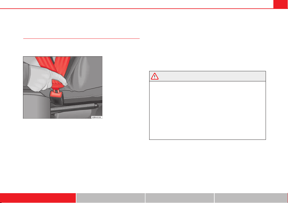
Seat belts
Seat belt adjustment
The seat belts for the front and rear occupants are locked in-
to position by a latch.
Fig. 11 Belt buckle and
latch plate of seat belt
The seat belt cannot offer its full protection if the seat belt is not
positioned correctly.
– Adjust the seat and head restraint correctly.
– To fasten the belt, take hold of the latch plate and pull it slowly
across your chest and lap.
– Insert the latch plate into the buckle for the appropriate seat
and push it down until it is securely locked with an audible click
⇒ Fig. 11.
– Pull the belt to ensure that the latch plate is securely engaged
in the buckle.
The seat belts are equipped with an automatic retractor on the shoulder
strap. Full freedom of movement is permitted when the shoulder belt is
pulled slowly. However, during sudden braking, during travel in steep areas
or bends and during acceleration, the automatic retractor on the shoulder
belt is locked.
The automatic belt retractors on the front seats are fitted with seat belt ten-
sioners ⇒ page 28.
WARNING
● An incorrectly worn seat belt can cause severe injuries in the event of
an accident.
● The seat belts offer best protection only when the backrests are in an
upright position and the seat belts have been fastened properly.
● Never put the latch plate in the buckle of another seat. If you do this,
the seat belt will not protect you properly and the risk of injury is in-
creased.
● If a vehicle occupant is incorrectly belted in, the seat belt cannot pro-
tect him or her properly. An incorrectly positioned seat belt can cause ex-
tremely severe injuries.
● Always engage the retractor lock when you are securing a child seat
in group 0, 0+ or 1 ⇒ page 47.
Safety First Operating instructions Practical Tips Technical specifications
26 Seat belts
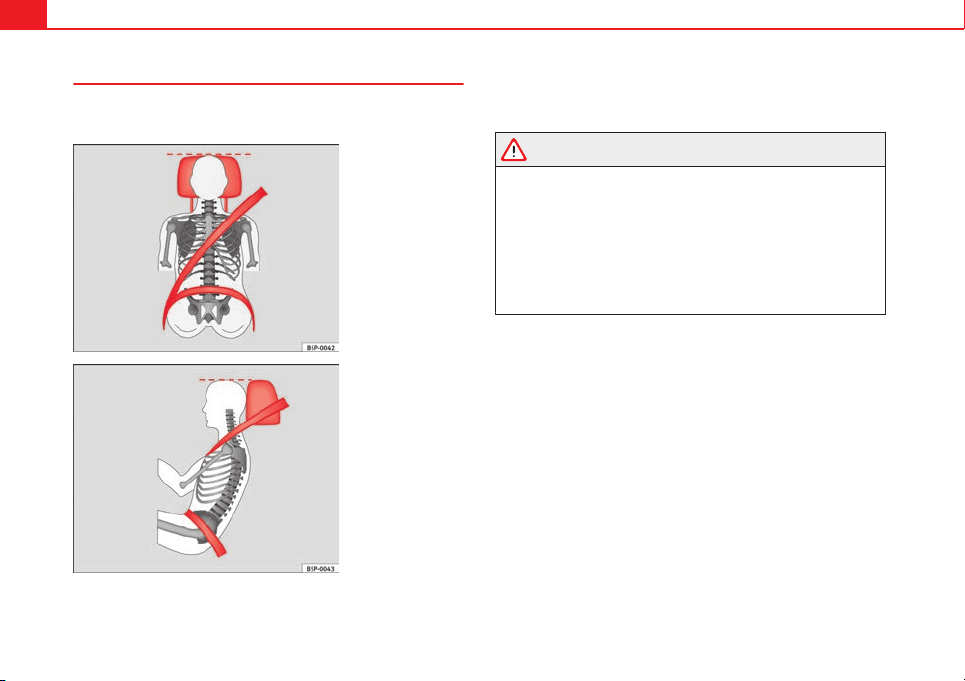
Seat belt position
Seat belts offer their maximum protection only when they
are properly positioned.
Fig. 12 Correct seat belt
and head restraint posi-
tions, viewed from front
Fig. 13 Correct seat belt
and head restraint posi-
tions, viewed from side
The following features are available to adjust the seat belt in the shoulder
region:
● front seat height adjustment*.
WARNING
● An incorrectly worn seat belt can cause severe injuries in the event of
an accident.
● The shoulder part of the seat belt must lie on the centre of the shoul-
der, never across the neck. The seat belt must lie flat and snugly on the
torso ⇒ Fig. 12.
● The lap part of the seat belt must lie across the pelvis, never across
the stomach. The seat belt must lie flat and snugly on the pelvis
⇒ Fig. 13. Pull the belt tight if necessary to take up any slack.
● Read and observe the warnings ⇒ page 23.
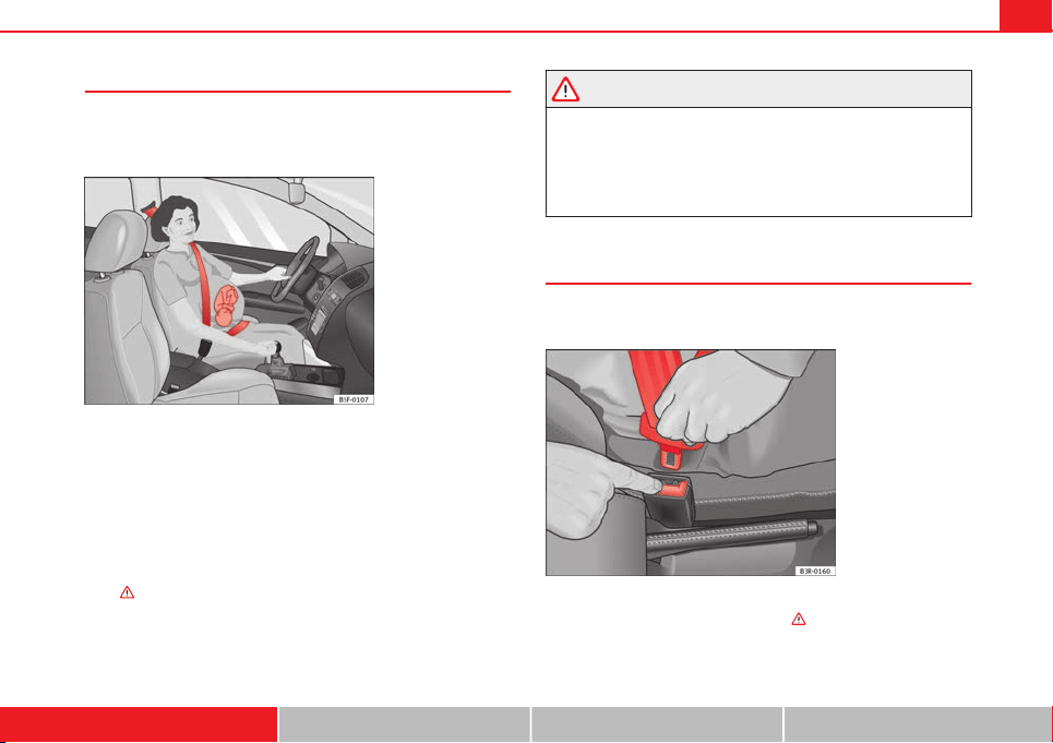
27Seat belts
Pregnant women must also fasten their seat belts properly
The best protection for the unborn child is for the mother to
wear the seat belt properly at all times during the pregnan-
cy.
Fig. 14 Positioning seat
belts during pregnancy
The seat belt provides maximum protection only when the seat belt
is properly positioned ⇒ page 26.
– Adjust the front seat and head restraint correctly ⇒ page 10.
– Holding the latch plate, pull the belt evenly across your chest
and as low as possible over the pelvis ⇒ Fig. 14.
– Insert the latch plate into the buckle for the corresponding seat
and push it down until it is securely locked with an audible click
⇒
.
– Pull the belt to ensure that the latch plate is securely engaged
in the buckle.
WARNING
● An incorrectly worn seat belt can cause severe injuries in the event of
an accident.
● For pregnant women, the lap part of the seat belt must lie as low as
possible over the pelvis, never across the stomach, and always lie flat so
that no pressure is exerted on the abdomen.
● Read and observe the warnings ⇒ page 23.
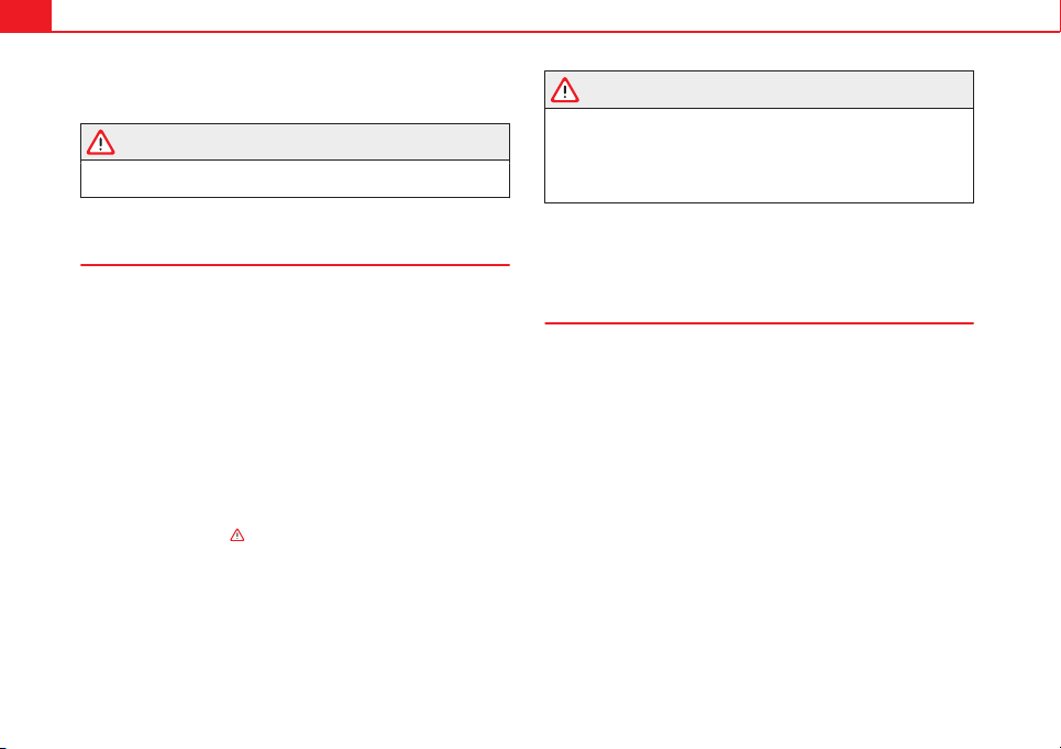
Seat belt release
The seat belt must not be unfastened until the vehicle has
come to a standstill.
Fig. 15 Remove latch
plate from buckle
– Press the red button on the belt buckle
⇒
Fig. 15. The latch
plate is released and springs out
⇒
.
Safety First Operating instructions Practical Tips Technical specifications
28 Seat belts
– Guide the belt back by hand so that it rolls up easily and the
trim is not damaged.
WARNING
Never unbuckle a seat belt while the vehicle is in motion. If you do, you
increase the risk of sustaining severe or fatal injuries.
Incorrectly fastened seat belts
Incorrectly worn seat belts can cause severe or even mortal
injuries.
Seat belts can provide optimal protection only if the belt web is
properly worn. The seat belts must be fastened exactly in the order
described in this chapter. An incorrect sitting position impairs sub-
stantially the protection a seat belt offers and can lead to severe or
fatal injuries. The risk of severe or fatal injuries is especially in-
creased when a deploying airbag strikes a vehicle occupant who
has assumed an incorrect sitting position. As the driver, you are re-
sponsible for yourself and all passengers, especially children.
Therefore:
– Never allow anyone to wear the seat belt incorrectly while the
vehicle is moving ⇒
.
WARNING
● An incorrectly worn seat belt increases the risk of severe injuries.
● Before every trip, instruct your passengers to adjust their seat belts
properly and to wear them for the whole journey.
● Read and always observe information and warnings concerning the
use of seat belts ⇒ page 23.
Seat belt tensioners
Function of the seat belt tensioner
During a frontal collision, the seat belts on the front seats
are retracted automatically.
The seat belts for the occupants in the front seats are equipped with belt
tensioners. Sensors will only trigger the belt tensioners during severe head-
on, lateral and rear collisions, and only if the seat belt is actually being
worn. This retracts and tightens the seat belts, reducing the forward motion
of the occupants.
The seat belt tensioner can be triggered only once.
The seat belt tensioners will not be triggered in the event of a light frontal,
side or rear collision, if the vehicle overturns or in situations where no large
forces act on the front, side or rear of the vehicle.

29Seat belts
Note
● If the seat belt tensioners are triggered, a fine dust is produced. This is
normal and it is not an indication of fire in the vehicle.
● The relevant safety requirements must be observed when the vehicle or
components of the system are scrapped. Specialised workshops are famili-
ar with these regulations, which are also available to you.
Service and disposal of belt tensioners
The belt tensioners are components of the seat belts that are installed in
the seats of your vehicle. If you work on the belt tensioners or remove and
install parts of the system when performing other repair work, the seat belt
may be damaged. The consequence may be that, in the event of an acci-
dent, the belt tensioners function incorrectly or not at all.
So that the effectiveness of the seat belt tensioner is not reduced and that
removed parts do not cause any injuries or environmental pollution, regula-
tions, which are known to the specialised workshops, must be observed.
WARNING
● Improper use or repairs not carried out by qualified mechanics in-
crease the risk of severe or fatal injuries. The belt tensioners may fail to
trigger or may trigger in the wrong circumstances.
● Never attempt to repair, adjust, remove or install parts of the belt ten-
sioners or seat belts.
● The seat belt tensioner, seat belt and automatic retractor cannot be
repaired.
WARNING (Continued)
● Any work on the belt tensioners and seat belts, including the removal
and refitting of system parts in conjunction with other repair work, must
be performed by a specialised workshop only.
● The belt tensioners will only provide protection for one accident and
must be changed if they have been activated.
Safety First Operating instructions Practical Tips Technical specifications
30 Airbag system
Airbag system
Brief introduction
Why wear a seat belt and assume the correct sitting
position?
For the inflating airbags to achieve the best protection, the
seat belt must always be worn properly and the correct sit-
ting position must be assumed.
For your own safety and the safety of the passengers, please en-
sure the following before driving:
– Always wear the seat belt properly ⇒ page 19.
– Adjust the driver seat and the steering wheel correctly
⇒ page 11.
– Adjust the front passenger seat correctly ⇒ page 12.
– Adjust the head restraint correctly ⇒ page 14.
– Use the correct child restraint system to protect children in your
vehicle ⇒ page 47.
The airbag is deployed at high speed in fractions of a second. If you have an
incorrect seating position at the time the airbag is deployed, it could cause
you critical injuries. Therefore, it is essential that all vehicle occupants as-
sume a correct sitting position while travelling.
Sharp braking before an accident may cause a passenger not wearing a seat
belt to be thrown forward into the area of the deploying airbag. In this case,
the inflating airbag may inflict critical or fatal injuries on the occupant. This
also applies to children.
Always maintain the greatest possible distance between yourself and the
front airbag. This way, the front airbags can completely deploy when trig-
gered, providing their maximum protection.
The most important factors that will trigger an airbag are: the type of acci-
dent, the angle of collision and the speed of the vehicle.
Whether the airbags are triggered depends primarily on the vehicle deceler-
ation rate resulting from the collision and detected by the control unit. If the
vehicle deceleration occurring during the collision and measured by the
control unit remains below the specified reference values, the front, side
and/or curtain airbag will not be triggered. Take into account that the visible
damage in a vehicle involved in an accident, no matter how serious, is not a
determining factor for the airbags to have been triggered.
WARNING
● Wearing the seat belt incorrectly or assuming an incorrect sitting po-
sition can lead to critical or fatal injuries.
● All vehicle occupants, including children, who are not properly belted
can sustain critical or fatal injuries if the airbag is triggered. Children up
to 12 years old should always travel on the rear seat. Never transport
children in the vehicle if they are not restrained or the restraint system is
not appropriate for their age, size or weight.
● If you are not wearing a seat belt, if you lean forward or to the side
while travelling or assume an incorrect sitting position, there is a sub-
stantially increased risk of injury. This increased risk of injury will be fur-
ther increased if you are struck by an inflating airbag.
31Airbag system
WARNING (Continued)
● To reduce the risk of injury from an inflating airbag, always wear the
seat belt properly ⇒ page 19.
● Always adjust the front seats properly.
The danger of fitting a child seat on the front passenger
seat
Rear-facing child seats must never be used on the front pas-
senger seat when the front passenger airbag is enabled.
The front passenger front airbag is a serious risk for a child if it is activated.
The front passenger seat is life threatening to a child if he/she is transpor-
ted in a rear-facing child seat. Children up to 12 years old should always
travel on the rear seat.
If a rear-facing child seat is secured to the front passenger seat, an inflating
airbag can strike it with such force that it can cause critical or fatal injuries.
Therefore we strongly recommend you to transport children on the rear
seats. That is the safest place for children in the vehicle. Alternatively, the
front passenger airbag can be disabled with a key-operated switch
⇒ page 44. When transporting children, use a child seat suitable for the
age and size of each child ⇒ page 47.
For those vehicles that do not include a key lock switch to turn the airbag
off, a Technical Service must be consulted.
WARNING
● If a child seat is secured to the front passenger seat, the risk to the
child of sustaining critical or fatal injuries in the event of an accident in-
creases.
● Never secure a rear-facing child seat to the front passenger seat if the
front passenger airbag is enabled. The child can suffer critical or fatal in-
juries if the front passenger airbag is triggered.
● An inflating front passenger airbag can strike the rear-facing child
seat and project it with great force against the door, the roof or the back-
rest.
● For those vehicles that do not include a key lock switch to turn the
airbag off, a Technical Service must be consulted.
● If, under special circumstances, it is necessary to transport a child in
a rear-facing child seat on the front passenger seat, it is absolutely es-
sential that you observe the following safety measures:
– Deactivate the front passenger airbag ⇒ page 44.
– Child seats must be approved by the child seat manufacturer for
use on a front passenger seat with front or side airbag.
– Follow the installation instructions given by the child seat manu-
facturer and observe the safety instructions ⇒ page 47, Child safe-
ty.
– Before properly installing the child seat, push the front passenger
seat completely backwards so that the greatest possible distance to
the front passenger airbag is ensured.
– Ensure that no objects prevent the front passenger seat from being
pushed completely back.
– The backrest of the front passenger seat must be in an upright po-
sition.
Safety First Operating instructions Practical Tips Technical specifications

32 Airbag system
Types of front passenger front airbag systems
There are two different SEAT front passenger front airbag systems:
A B
Characteristics of the front passen-
ger front airbag that can only be dis-
abled in a specialised workshop.
Characteristics of the front passen-
ger front airbag that can be disabled
manually ⇒ page 44.
– Control lamp on the instrument
panel.
– Front passenger front airbag on
the dash panel.
– Control lamp on the instrument
panel.
– Control lamp on the dash panel.
PASSENGER AIR BAG .
– Control lamp on the dash panel.
PASSENGER AIR BAG .
– Switch on the dash panel glove
compartment, on the passenger
side.
– Front passenger front airbag in the
dash panel.
Name: airbag system.
Name: airbag system with front pas-
senger front airbag disabling.
33Airbag system
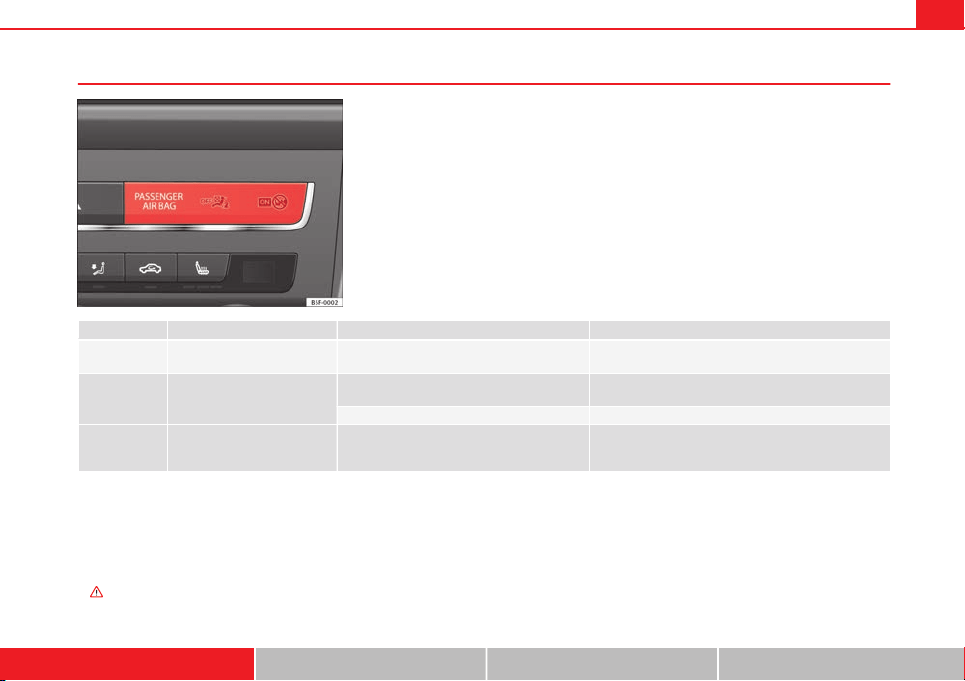
Control lamp
Fig. 16 Control lamp for
disabling the front pas-
senger front airbag on
the dash panel
lights up Digit Possible cause Solution
Instrument panel Fault in airbag system and seat belt tensioners.
Have the system checked immediately by a specialised
workshop.
Dash panel
Fault in the airbag system.
Have the system checked immediately by a specialised
workshop.
Front passenger front airbag disabled. Check whether the airbag should remain disabled.
Dash panel Front passenger front airbag enabled.
No solution. The control lamp switches off about 60 sec-
onds after ignition is turned on or after enabling of the
front passenger front airbag with the key lock switch.
Several warning and control lamps should light up for a few seconds when
the ignition is switched on, signalling that the function is being verified.
They will switch off after a few seconds.
If the PASSENGER AIR BAG control lamp does not remain lit or if it is lit
together with the control lamp on the instrument panel and the front pas-
senger front airbag is disabled, there may be a fault in the airbag system
⇒
.
Safety First Operating instructions Practical Tips Technical specifications
34 Airbag system
WARNING
In the event of a fault in the airbag system, the airbag may not trigger
correctly, may fail to trigger or may even trigger unexpectedly, leading to
severe or fatal injuries.
● Have the airbag system checked immediately by a specialised work-
shop.
● Never mount a child seat in the front passenger seat or remove the
mounted child seat! The front passenger front airbag may deploy during
an accident in spite of the fault.
CAUTION
Always pay attention to any lit control lamps and to the corresponding de-
scriptions and instructions to avoid damage to the vehicle.
Repairs, maintenance and disposal of airbags
The parts of the airbag system are installed in various places in your vehi-
cle. If work is carried out on the airbag system or parts have to be removed
and fitted on the system when performing other repair work, parts of the air-
bag system may be damaged. In the event of an accident this could cause
the airbag to inflate incorrectly or not inflate at all.
The relevant safety requirements must be observed when the vehicle or
components of the airbag are scrapped. Specialised workshops and vehicle
disposal centres are familiar with these requirements.
WARNING
● If repairs are not carried out by a professional, or if the airbags are
used incorrectly, the risk of severe or fatal injuries is increased. The air-
bags may fail to inflate, or could inflate in the wrong circumstances.
● Do not cover or stick anything on the steering wheel hub or the sur-
face of the airbag unit on the passenger side of the dash panel, and do
not obstruct or modify them in any way.
● It is important not to attach any objects such as cup holders or tele-
phone mountings to the surfaces covering the airbag units.
● To clean the steering wheel or dash panel, you may use only a dry or a
water-moistened cloth. Never clean the dash panel and the airbag mod-
ule surface with cleaners containing solvents. Solvents cause the surface
to become porous. If the airbag triggered, plastic parts could become de-
tached and cause injuries.
● Never attempt to repair, adjust, remove or install parts of the airbag
system.
● Any work on the airbag system or removal and installation of the air-
bag components for other repairs (such as repairs to the steering wheel)
should be performed only by a specialised workshop. Specialised work-
shops have the necessary tools, repair information and qualified person-
nel.
● We strongly recommend you to go to a specialised workshop for all
work on the airbag system.
● Never attempt to alter the front bumper or the body.
● The airbags provide protection for just one accident; replace them
once they have deployed.
For the sake of the environment
The airbags, which are a special type of waste, must be disposed of through
an authorised service, because they contain pyrotechnic elements.
35Airbag system
Front airbags
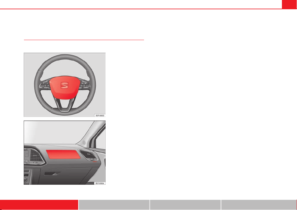
Description of front airbags
The airbag system is not a substitute for the seat belts.
Fig. 17 Driver airbag lo-
cated in steering wheel
Fig. 18 Front passenger
airbag located in dash
panel
The front airbag for the driver is located in the steering wheel ⇒ Fig. 17 and
the airbag for the front passenger is located in the dash panel ⇒ Fig. 18. Air-
bags are identified by the word “AIRBAG”.
In conjunction with the seat belts, the front airbag system gives the front
occupants additional protection for the head and chest in the event of a se-
vere frontal collision ⇒ page 37, Safety notes on the front airbag system.
In addition to their normal function of restraining the occupants, the seat
belts also hold the driver and front passenger in a position where the air-
bags can provide maximum protection in a frontal collision.
The airbag system is not a substitute for seat belts, but it is an integral part
of the vehicle's overall passive safety system. Please bear in mind that the
airbag system can only work effectively when the vehicle occupants are
wearing their seat belts correctly and have adjusted the head restraints
properly. Therefore, it is most important to wear the seat belts at all times,
not only because this is required by law in most countries, but also for your
safety ⇒ page 19, Brief introduction.
The main parts of the front airbag system are:
● an electronic control and monitoring system (control unit)
● the two front airbags (airbag with gas generator) for the driver and front
passenger
● a control lamp in the dash panel
The airbag system operation is monitored electronically. The airbag control
lamp will light up for a few seconds every time the ignition is switched on
(self-diagnosis).
There is a fault in the system if the control lamp :
● does not light up when the ignition is switched on
● turns off after 4 seconds after the ignition is switched on
● turns off and then lights up again after the ignition is switched on
● lights up or flashes while the vehicle is moving
Safety First Operating instructions Practical Tips Technical specifications
36 Airbag system
The front airbag system will not be triggered if:
● the ignition is switched off
● there is a minor frontal collision
● there is a side collision
● there is a rear-end collision
● the vehicle turns over
WARNING
● The seat belts and airbags can only provide maximum protection if
the occupants are seated correctly ⇒ page 10, Sitting position for vehicle
occupants.
● If a fault has occurred in the airbag system, have the system checked
immediately by a specialised workshop. Otherwise, during a frontal colli-
sion the system may fail to trigger, or not trigger correctly.
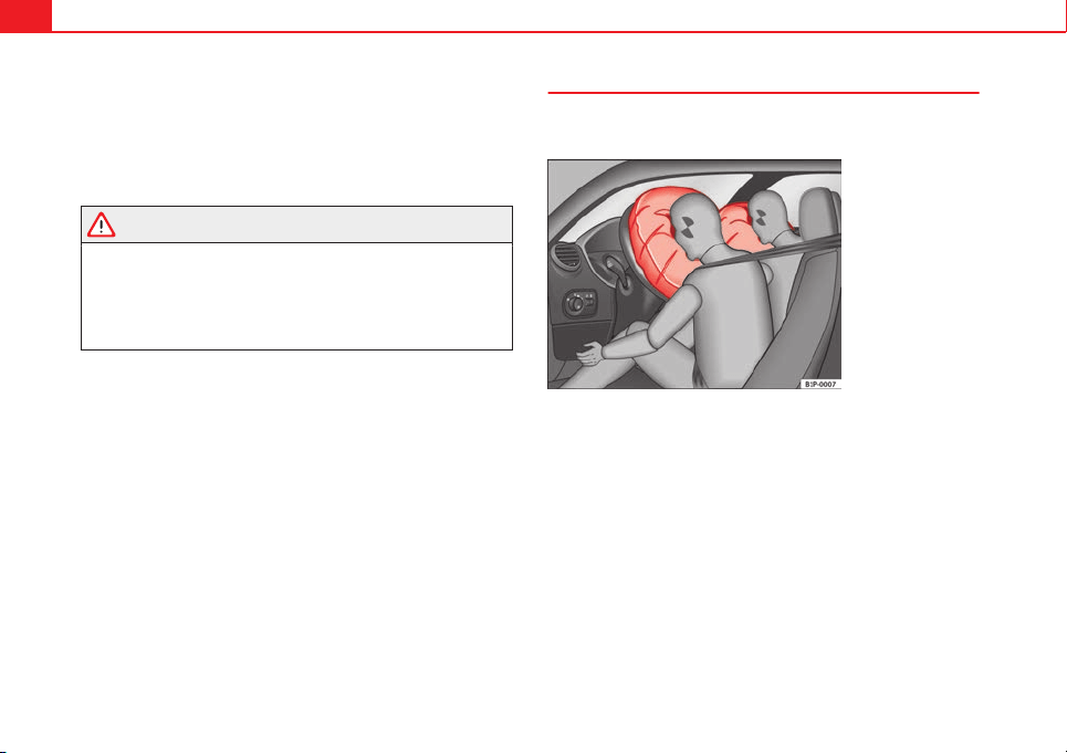
Operation of front airbags
Inflated airbags reduce the risk of injuries to the head or
chest.
Fig. 19 Inflated front air-
bags
The airbag system is designed so that the airbags for the driver and front
passenger are triggered in a severe frontal collision.
In certain types of accident the front, curtain and side airbags may be trig-
gered together.
When the system is triggered, the airbags fill with a propellant gas and de-
ploy in front of the driver and front passenger
⇒
Fig. 19. The fully deployed
airbags cushion the forward movement of the front occupants and help to
reduce the risk of injury to the head and the upper part of the body.
The special design of the airbag allows the controlled escape of the propel-
lant gas when an occupant puts pressure on the bag. Thus, the head and
chest are surrounded and protected by the airbag. After the collision, the
airbag deflates sufficiently to allow visibility.
37Airbag system
The airbags deploy extremely rapidly, within thousandths of a second, to
provide additional protection in the event of an accident. A fine dust may
develop when the airbag deploys. This is normal and it is not an indication
of fire in the vehicle.
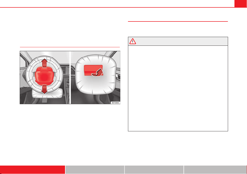
Airbag covers when the frontal airbags are triggered
Fig. 20 Airbag covers reacting when the front airbags are triggered
The airbag covers fold out of the steering wheel or dash panel when the
driver and front passenger airbags are triggered
⇒
Fig. 20. The airbag cov-
ers remain connected to the steering wheel or the dash panel.
Safety notes on the front airbag system
If you use airbags correctly, they can considerably reduce
the risk of injury in many kinds of accident.
WARNING
● It is important for the driver and front passenger to keep a distance of
at least 25 cm from the steering wheel and dash panel. If the minimum
distance is not observed then the airbags do not correctly protect the ve-
hicle occupants; risk of fatal injuries! In addition, the front seats and
head restraints must always be positioned correctly for the height of the
occupant.
● If you are not wearing a seat belt, if you lean forward or to the side
while travelling or assume an incorrect sitting position, there is a sub-
stantially increased risk of injury. This increased risk of injury will be fur-
ther increased if you are struck by an inflating airbag.
● Never let a child travel on the front seat without an appropriate re-
straint system. If the airbag is triggered in an accident, children can sus-
tain serious or fatal injuries from the airbag as it inflates ⇒ page 47.
● The deployment space between the front passengers and the airbags
must not in any case be occupied by other passenger, pets and objects.
● The airbags provide protection for just one accident; replace them
once they have deployed.
● It is also important not to attach any objects such as cup holders or
telephone mountings to the surfaces covering the airbag units.
● Do not attempt to modify components of the airbag system in any
way.
Safety First Operating instructions Practical Tips Technical specifications
38 Airbag system
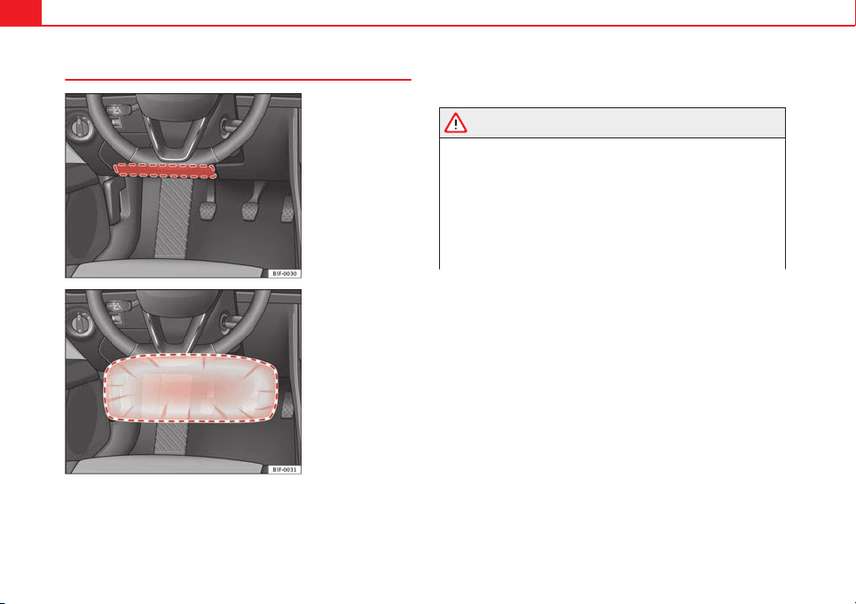
Knee airbag*
Fig. 21 On the driver
side: location of the knee
airbag
Fig. 22 On the driver
side: Radius of action of
the knee airbag
The knee airbag is located on the driver side below the dash panel
⇒
Fig. 21. Airbags are identified by the word “AIRBAG”.
The area framed in red ⇒ Fig. 22 is covered by the knee airbag when it is
deployed (deployment area). Therefore, objects should never be placed or
mounted in these areas.
WARNING
The airbag is deployed at high speed in fractions of a second.
● The knee airbag is deployed in front of the driver's knees. Always
keep the deployment areas of the knee airbags free.
● Never not fix objects to the cover or in the deployment area of the
knee airbag.
● Adjust the driver seat so that there is a distance of at least 10 cm (4
inches) between your knees and the location of the knee airbag. If you
physical constitution prevents you from meeting these requirements,
make sure you contact a specialised workshop.
39Airbag system
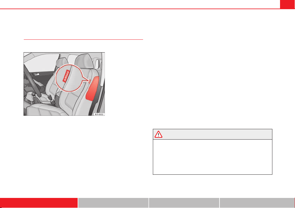
Side airbags*
Description of side airbags
The airbag system is not a substitute for the seat belts.
Fig. 23 Side airbag in
driver seat
The side airbags are located in the backrest cushions of the driver seat
⇒
Fig. 23 and the front passenger seat as well as in the rear seats*. The lo-
cations are identified by the text “AIRBAG” in the upper region of the backr-
ests.
Together with the seat belts, the side airbag system gives the front seat oc-
cupants additional protection for the upper body in the event of a severe
side collision
⇒
page 41, Safety notes on the operation of the side airbag
system.
In a side collision, the side airbags reduce the risk of injury to passengers
on the front seats to the areas of the body facing the impact. In addition to
their normal function of protecting the occupants in a collision, the seat
belts also hold the passengers in the front seats and the outer rear seats in
a position where the side airbags can provide maximum protection.
The airbag system is not a substitute for seat belts, but it is an integral part
of the vehicle's overall passive safety system. Please bear in mind that the
airbag system can only work effectively when the occupants are wearing
their seat belts. Therefore, it is most important to wear the seat belts at all
times, not only because this is required by law in most countries, but also
for your safety ⇒ page 19, Brief introduction.
The side airbag system will not be triggered if:
● the ignition is switched off
● there is a minor side collision
● there is a frontal collision
● there is a rear-end collision
● the vehicle turns over
The main parts of the airbag system are:
● an electronic control and monitoring system (control unit)
● the side airbags in the sides of the backrests of the front and rear seats
● a control lamp in the dash panel
The airbag system operation is monitored electronically. The airbag control
lamp will light up for approx. 4 seconds every time the ignition is switched
on (self-diagnosis).
WARNING
● In a side-on collision the side airbags will not work if the sensors do
not correctly measure the pressure increase on the interior of the doors,
due to air escaping through the areas with holes or openings in the door
panel.
● Never drive the vehicle if the interior panels have been removed.
● Never drive if the interior door panels have been removed or if the
panels have not been correctly fitted.
Safety First Operating instructions Practical Tips Technical specifications
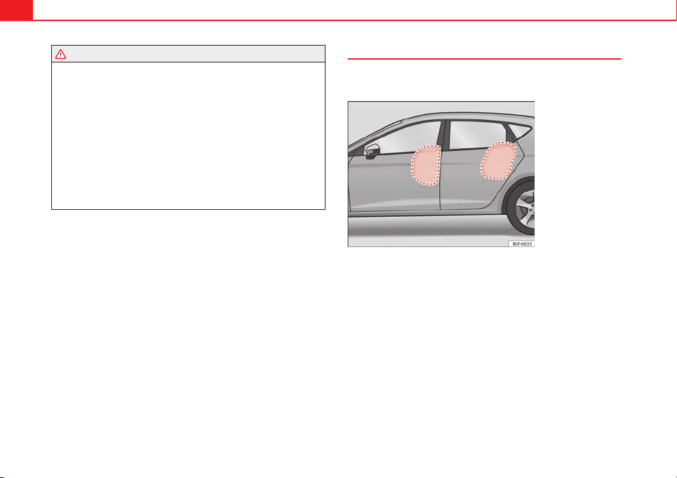
40 Airbag system
WARNING (Continued)
● Never drive the vehicle if the loudspeakers in the door panels have
been removed, unless the holes left by the loudspeakers have been cor-
rectly closed.
● Always check that the openings are closed or covered if loudspeakers
or other equipment are fitted in the interior door panels.
● Any work carried out to the doors should be made in an authorised
specialised workshop.
● The seat belts and airbags can only provide maximum protection if
the occupants are seated correctly ⇒ page 10, Sitting position for vehicle
occupants.
● If a fault has occurred in the airbag system, have the system checked
immediately by a specialised workshop. Otherwise, during a side colli-
sion, the system may fail to trigger, or not trigger correctly.
Operation of side airbags
Inflated airbags can reduce the risk of head or chest injury
in many side impact collisions.
Fig. 24 Illustration of
completely inflated side
airbags on left side of ve-
hicle
In some side collisions, the side airbag is triggered on the impact side of
the vehicle
⇒
Fig. 24.
In certain types of accident the front, curtain and side airbags may be trig-
gered together.
When the system is triggered, the airbag is filled with propellant gas.
The airbags deploy extremely rapidly, within thousandths of a second, to
provide additional protection in the event of an accident. A fine dust may
develop when the airbag deploys. This is normal and it is not an indication
of fire in the vehicle.
The fully deployed airbags cushion the movement of the occupants of the
front seats and the outer rear seats and help to reduce the risk of injury to
the upper body.
41Airbag system
The special design of the airbag allows the controlled escape of the propel-
lant gas when an occupant puts pressure on the bag. Thus, the head and
chest are surrounded and protected by the airbag.
Safety notes on the operation of the side airbag system
If airbags are used correctly, they can considerably reduce
the risk of injury in side impact collisions.
WARNING
● If you do not wear a seat belt, if you lean forward, or are not seated
correctly while the vehicle is in motion, you are at a greater risk of injury
if the side airbag system is triggered in an accident.
● In order for the side airbags to provide their maximum protection, the
prescribed sitting position must always be maintained with seat belts
fastened while travelling.
● Occupants of the outer seats must never carry any objects or pets in
the deployment space between them and the airbags, or allow children
or other passengers to travel in this position. It is also important not to
attach any accessories (such as cup holders) to the doors. This would im-
pair the protection offered by the side airbags.
● The built-in coat hooks should be used only for lightweight clothing.
Do not leave any heavy or sharp-edged objects in the pockets.
● Great forces, such as hard blows or kicks, must not be exerted upon
the backrest bolster because the system may be damaged. In this case,
the side airbags would not be triggered.
WARNING (Continued)
● Under no circumstances should protective covers be fitted over seats
with side airbags unless the covers have been approved for use in your
vehicle. Because the airbag deploys from the side of the backrest, the
use of conventional seat covers would obstruct the side airbag, seriously
reducing the airbag's effectiveness.
● Any damage to the original seat upholstery or around the seams of
the side airbag units must be repaired immediately by a specialised
workshop.
● The airbags provide protection for just one accident; replace them
once they have deployed.
● When children assume an incorrect sitting position, they expose
themselves to an increased risk of injury in the event of an accident. This
is particularly the case if the child is travelling on the front passenger
seat and the airbag system is triggered in an accident; this could have
critical consequences including serious injury or death ⇒ page 47.
● Any work on the side airbag system or removal and installation of the
airbag components for other repairs (such as removal of the front seat)
should only be performed by a specialised workshop. Otherwise, faults
may occur during the airbag system operation.
● Do not attempt to modify components of the airbag system in any
way.
● The side and head airbags are managed through sensors located in
the interior of the front doors. To ensure the correct operation of the side
and head airbags neither the doors nor the door panels should be modi-
fied in any way (e.g. fitting loudspeakers). If the front door is damaged,
the airbag system may not work correctly. All work carried out on the
front door must be done in a specialised workshop.
Safety First Operating instructions Practical Tips Technical specifications
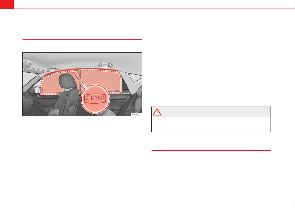
42 Airbag system
Curtain airbags*
Description of curtain airbags
The airbag system is not a substitute for the seat belts.
Fig. 25 Location of curtain airbags
The curtain airbags are located on both sides in the interior above the doors
⇒ Fig. 25 and are identified with the text “AIRBAG”.
In conjunction with the seat belts, the curtain airbag system gives the vehi-
cle occupants additional protection for the head and upper body in the
event of a severe side collision ⇒ page 43, Safety notes on the operation
of the curtain airbag system.
The airbag system is not a substitute for seat belts, but it is an integral part
of the vehicle's overall passive safety system. Please bear in mind that the
airbag system can only work effectively when the vehicle occupants are
wearing their seat belts correctly and have adjusted the head restraints
properly. Therefore, it is most important to wear the seat belts at all times,
not only because this is required by law in most countries, but also for your
safety ⇒ page 19, Brief introduction.
The main parts of the curtain airbag system are:
● an electronic control and monitoring system (control unit)
● the curtain airbags (airbags with gas generator) for the driver, front pas-
senger and passengers on the rear seats
● a control lamp in the dash panel
The airbag system operation is monitored electronically.
The curtain airbag system will not be triggered if:
● the ignition is switched off
● there is a frontal collision
● there is a rear-end collision
● the vehicle turns over
● there is a minor side collision
WARNING
If a fault has occurred in the airbag system, have the system checked im-
mediately by a specialised workshop. Otherwise there is a danger that
during a collision, the system may fail to trigger, or not trigger correctly.
Operation of curtain airbags
Fully inflated airbags reduce the risk of head or chest injury
in a side collision.
During some side collisions the curtain airbag is triggered on the impact
side of the vehicle ⇒ Fig. 25.
43Airbag system
In certain types of accident the front, side and curtain airbags may be trig-
gered together.
When the system is triggered, the airbag is filled with propellant gas. In the
process, the curtain airbag covers the side windows and door pillars.
The airbags deploy extremely rapidly, within thousandths of a second, to
provide additional protection in the event of an accident. A fine dust may
develop when the airbag deploys. This is normal and it is not an indication
of fire in the vehicle.
The fully deployed airbags cushion the movement of the front occupants
and help to reduce the risk of injury to the upper body.
The special design of the airbag allows the controlled escape of the propel-
lant gas when an occupant puts pressure on the bag. Thus, the head and
chest are surrounded and protected by the airbag.
Safety notes on the operation of the curtain airbag system
If you use airbags correctly, they can considerably reduce
the risk of injury in many kinds of accident.
WARNING
● In order for the side airbags to provide their maximum protection, the
prescribed sitting position must always be maintained with seat belts
fastened while travelling.
● For safety reasons, the curtain airbag must be disabled in those vehi-
cles fitted with a screen dividing the interior of the vehicle. See a Techni-
cal Service to make this adjustment.
WARNING (Continued)
● There must be no other persons, animals or objects between the oc-
cupants of the outer seats and the deployment space of the curtain air-
bags so that the curtain airbag can deploy without restriction and pro-
vide the greatest possible protection. Therefore, sun blinds which have
not been expressly approved for use in your vehicle may not be attached
to the side windows.
● The built-in coat hooks should be used only for lightweight clothing.
Do not leave any heavy or sharp-edged objects in the pockets. Please, do
not hang the clothes on coat hangers.
● The airbags provide protection for just one accident; replace them
once they have deployed.
● Any work on the curtain airbag system or removal and installation of
the airbag components for other repairs (such as removal of the roof lin-
ing) should only be performed by a specialised workshop. Otherwise,
faults may occur during the airbag system operation.
● Do not attempt to modify components of the airbag system in any
way.
● The side and head airbags are managed through sensors located in
the interior of the front doors. To ensure the correct operation of the side
and head airbags neither the doors nor the door panels should be modi-
fied in any way (e.g. fitting loudspeakers). If the front door is damaged,
the airbag system may not work correctly. All work carried out on the
front door must be done in a specialised workshop.
Safety First Operating instructions Practical Tips Technical specifications
44 Airbag system
Deactivating airbags
Deactivating airbags
The deactivation of airbags corresponds only to certain cases, i.e. if:
● a child seat is required in the front passenger seat with the child facing
in the opposite direction to the direction of travel (in some countries, due to
divergent legal requirements, facing in the direction of travel) ⇒ page 49;
● despite the driver seat being in the correct position, a minimum dis-
tance of 25 cm cannot be maintained between the centre of the steering
wheel and the driver's torso.
● installation of special devices is required in the steering wheel area due
to a physical disability.
● if you have special seats installed (e.g. an orthopaedic seat without side
airbag).
The front passenger front airbag can be disabled using the switch
⇒ page 45.
We recommend that you contact an authorised SEAT dealer for the disabling
of other airbags.
Airbag system control
The airbag system availability is controlled electronically, regardless of
whether an airbag is disabled.
If an airbag was disabled using a diagnostics system:
● the airbag system warning lamp lights up after switching on the igni-
tion for about 4 seconds, and then flashes for about 12 seconds
If the airbag has been disabled with the airbag switch on the side of the
dash panel:
● the airbag control lamp will light up for about 4 seconds after the ig-
nition is switched on.
● The airbag is disabled, signalled with the warning lamp which
lights up with the word placed in the centre part of the
dash panel ⇒ Fig. 26.
Note
● Respect the current legislation in your country regarding the deactiva-
tion of airbags
● At your authorised SEAT dealer you can find information on which vehi-
cle airbags can be deactivated.
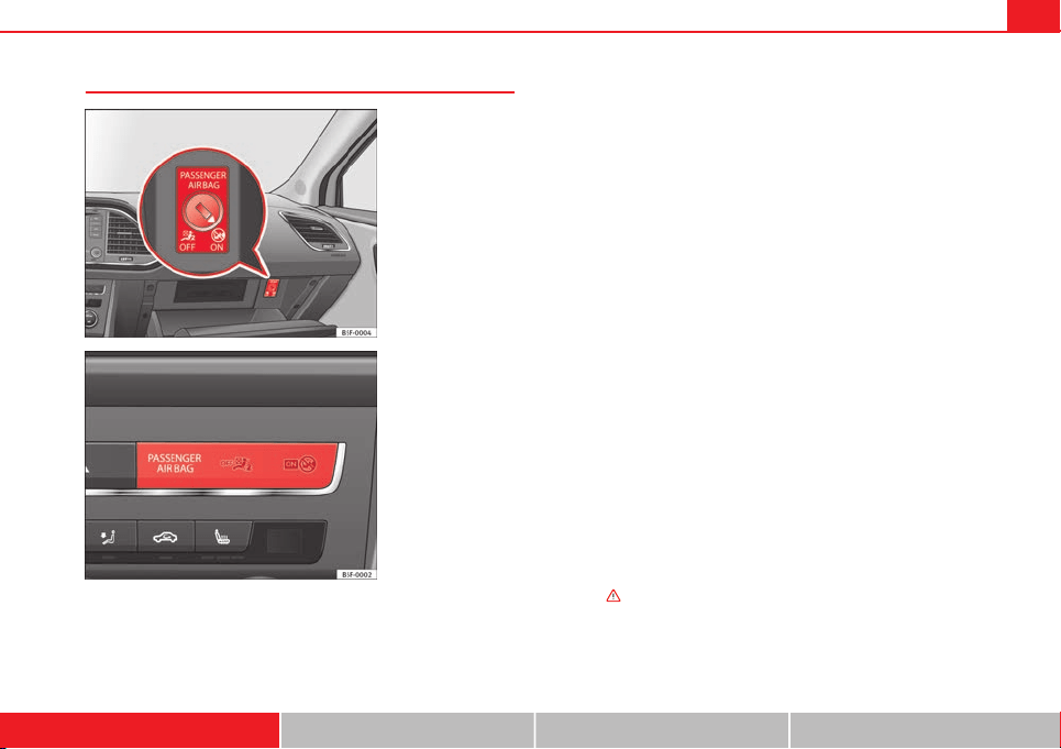
45Airbag system
Front passenger front airbag switch
Fig. 26 Front passenger
front airbag switch
Fig. 27 Warning lamp for
disabling the front pas-
senger airbag
The switch disables only the front passenger front airbag.
Disabling the airbag
– Switch the ignition off.
– Open the glove compartment on the front passenger side.
– Turn the airbag switch slot with the key to the OFF position
⇒ Fig. 26.
– Check, with the ignition switched on, that the control lamp
⇒ Fig. 27 lights up with the word in the
centre part of the dash panel.
Switching on the airbag
– Switch the ignition off.
– Turn the airbag switch slot with the key to the ON position
⇒ Fig. 26.
– Close the passenger side storage compartment.
– Check, with the ignition switched on, that the control lamp
⇒ Fig. 27 does not light up, with the word
in the centre part of the dash panel.
– The warning lamp is illuminated for 60 seconds in the cen-
tre part of the dash panel.
Control lamp with the word (front passenger airbag
disabled)
If the front passenger front airbag is disabled, after switching on the igni-
tion, the control lamp will light up for several seconds, then it will switch off
for about 1 s and then switch on again.
If the control lamp is flashing, there is a fault in the disabling of the airbag
system ⇒
. Please go immediately to an Official Service.
Safety First Operating instructions Practical Tips Technical specifications
46 Airbag system
WARNING
● The driver of the vehicle is responsible for disabling or switching on
the airbag.
● Always switch off the ignition before disabling the front passenger
airbag! Failure to do so could result in a fault in the airbag deactivation
system.
● If the control lamp (airbag deactivated) flashes, the front pas-
senger front airbag will not trigger in the event of an accident! Have the
system immediately checked by an Official Service.

47Child safety
Child safety
Brief introduction
Introduction
Statistics show that children are generally safer on the rear
seat than on the front passenger seat.
For safety reasons we recommend that children under 12 years of age travel
on the rear seats. Depending on their age, height and weight, children trav-
elling on the rear seat must use a child seat or a seat belt. For safety rea-
sons, the child seat should be installed in the centre of the rear seat or be-
hind the front passenger seat.
The physical laws involved and the forces acting in a collision apply also to
children ⇒ page 21.
But unlike adults, children do not have fully developed muscle and bone
structures. This means that children are subject to a greater risk of injury.
To reduce this risk, children must always use special child restraint systems
when travelling in the vehicle.
We recommend the use of child safety products from the SEAT Original Ac-
cessories Programme, which includes systems for all ages made by
“Peke”
1)
.
These systems have been especially designed and approved, complying
with the ECE-R44. regulation.
Follow the manufacturer's instructions and observe any statutory require-
ments when installing and using child seats. Always read and note
⇒ page 47.
We recommend you to always include the manufacturer's Child Seat Instruc-
tion Manual together with the on-board documentation.
Safety notes on using child seats
Proper use of child seats substantially reduces the risk of in-
jury in an accident!
As the driver, you are responsible for any children you transport in your vehi-
cle.
● Protect your children by properly using the appropriate child seats
⇒ page 49.
● Always ensure that the seat belt is properly positioned according to the
instructions provided by the manufacturer of the child seat.
● When travelling, do not allow children to distract you from traffic.
● Take breaks regularly during long trips. Take a break at least every two
hours.
1)
Not for all countries
Safety First Operating instructions Practical Tips Technical specifications
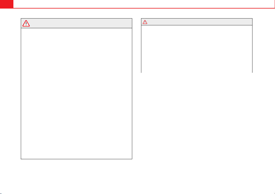
48 Child safety
WARNING
● Never install a child seat facing backwards on the front passenger
seat unless the front passenger front airbag has been disabled. Risk of
potentially fatal injuries to the child! However, if it is necessary, in excep-
tional cases, to transport a child in the front passenger seat, the front
passenger front airbag must always be disabled ⇒ page 44. If the pas-
senger seat has a height adjustment option, move it to the highest, most
upright position. If you have a fixed seat, do not install any child restraint
system in this location.
● For those vehicles that do not include a key lock switch to deactivate
the airbag, the vehicle must be taken to a Technical Service.
● All vehicle occupants, especially children, must assume the proper
sitting position and be properly belted in while travelling.
● Never hold children or babies on your lap, this can result in potential-
ly fatal injuries to the child!
● Never allow a child to be transported in a vehicle without being prop-
erly secured, or to stand up or kneel on a seat while travelling. In an acci-
dent, the child could be flung through the vehicle, causing possibly fatal
injuries to themselves and to the other vehicle occupants.
● If children assume an improper sitting position when the vehicle is
moving, they expose themselves to greater risk of injury in the event of a
sudden braking manoeuvre or in an accident. This is particularly impor-
tant if the child is travelling on the front passenger seat and the airbag
system is triggered in an accident; as this could cause serious injury or
even death.
● A suitable child seat can protect your child!
● Never leave an unsupervised child alone on a child seat or in the vehi-
cle.
● Depending on weather conditions, it may become extremely hot or
cold inside the vehicle. This can be fatal.
WARNING (Continued)
● Children who are less than 1.5 metres tall must not wear a normal
seat belt without a child seat, as this could cause injuries to the abdomi-
nal and neck areas during a sudden braking manoeuvre or in an accident.
● Do not allow the seat belt to become twisted or jammed, or to rub on
any sharp edges.
● Incorrectly worn seat belts can cause injuries even in a minor colli-
sion or in sudden braking manoeuvres.
● The seat belt provides maximum protection only when the seat belt is
properly positioned ⇒ page 25, Seat belts.
● Only one child may occupy a child seat ⇒ page 49, Child seats.
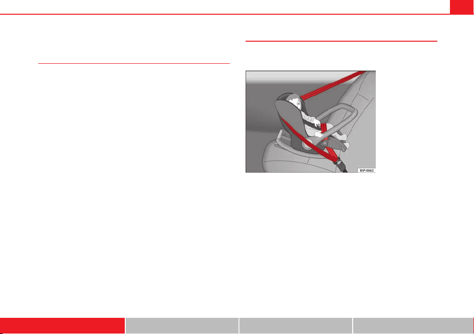
49Child safety
Child seats
Categorisation of child seats into groups
Use only child seats that are officially approved and suitable
for the child.
Child seats are subject to the regulation ECE-R 44. ECE-R stands for: Eco-
nomic Commission for Europe Regulation
The child seats are grouped into 5 categories:
Group 0: up to 10 kg
Group 0+: up to 13 kg
Group 1: from 9 to 18 kg
Group 2: from 15 to 25 kg
Group 3: from 22 to 36 kg
Child seats that have been tested and approved under the ECE R44 stand-
ard bear the test mark on the seat (the letter E in a circle with the test num-
ber below it).
Group 0 and 0+ child seats
A suitable child seat and a correctly adjusted seat belt can
help you to protect your child.
Fig. 28 A group 0 rear-
facing child seat fitted on
the rear seat
Group 0: Infants up to 10 kg (approx. 9 months) must travel in the direction
opposite to travel
⇒
Fig. 28.
Group 0+: Infants up to 13 kg (approx. 18 months) must travel in the direc-
tion opposite to travel
⇒
Fig. 28.
Follow the manufacturer's instructions and observe any statutory require-
ments when installing and using child seats.
We recommend you to always include the manufacturer's Child Seat Instruc-
tion Manual together with the on-board documentation.
SEAT recommends the use of child seats from the Original Accessories cata-
logue. These child seats have been designed and tested for use in SEAT ve-
hicles. You can find the right child seat for your model and age group at
SEAT dealers.
Safety First Operating instructions Practical Tips Technical specifications
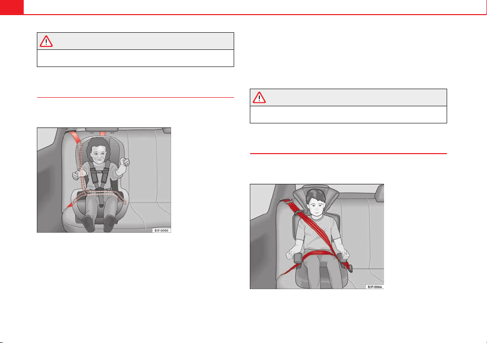
50 Child safety
WARNING
Read and always observe information and warnings concerning the use
of child seats ⇒ page 47.
Group 1 child seats
A suitable child seat and a correctly adjusted seat belt can
help you to protect your child.
Fig. 29 A category 1 for-
ward-facing child seat fit-
ted on the rear seat
Babies and young children between 9 and 18 kg can travel in the direction
of travel or in the reverse, depending on the seat type. For safety reasons it
is recommended that the child is transported in the direction opposite to
travel for as long as possible. Consult the instruction manual of the child
seat manufacturer for possible installation options.
Follow the manufacturer's instructions and observe any statutory require-
ments when installing and using child seats.
We recommend you to always include the manufacturer's Child Seat Instruc-
tion Manual together with the on-board documentation.
SEAT recommends the use of child seats from the Original Accessories cata-
logue. These child seats have been designed and tested for use in SEAT ve-
hicles. You can find the right child seat for your model and age group at
SEAT dealers.
WARNING
Read and always observe information and warnings concerning the use
of child seats ⇒ page 47.
Group 2 and 3 child seats
A suitable child seat and a correctly adjusted seat belt can
help you to protect your child.
Fig. 30 Forward-facing
child seat installed on
rear seat
51Child safety
The child seats in groups 2 and 3 must be mounted in the direction of
movement and using the vehicle’s seatbelt.
Follow the manufacturer's instructions and observe any statutory require-
ments when installing and using child seats.
We recommend you to always include the manufacturer's Child Seat Instruc-
tion Manual together with the on-board documentation.
SEAT recommends the use of child seats from the Original Accessories cata-
logue. These child seats have been designed and tested for use in SEAT ve-
hicles. You can find the right child seat for your model and age group at
SEAT dealers.
Group 2 child seats
Children under 7 years of age weighing between 15 and 25 kg are best pro-
tected by group 2 child seats together with properly adjusted seat belts.
Group 3 child seats
Children over 7 years of age weighing between 22 and 36 kg but less than
1.5 metres tall are best protected by child seats with head restraints togeth-
er with properly worn seat belts ⇒ Fig. 30.
WARNING
● The shoulder part of the seat belt must lie approximately on the cen-
tre of the shoulder, never across the neck or the arm. The seat belt must
lie close to the upper part of the body. The lap belt part must lie across
the pelvis, not across the stomach, and always fit closely. Pull the belt
tight if necessary to take up any slack ⇒ page 25, Seat belts.
● Read and always observe information and warnings concerning the
use of child seats ⇒ page 47.
Safety First Operating instructions Practical Tips Technical specifications
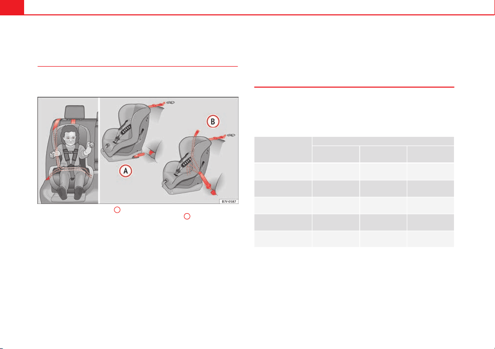
52 Child safety
Securing child seats
Ways to secure a child seat
A child seat can be secured differently on the rear seat and
on the front passenger seat.
Fig. 31 On the rear seats: figure
A
shows the basic child restraint system mounting
using lower retaining rings and the upper retaining strap figure
B
shows the child re-
straint system mounting using the vehicle seat belt
You can secure a child seat to the rear seat or front passenger seat in the
following ways:
● Child seats in groups 0 to 3 can be secured with a seat belt.
● Child seats in groups 0, 0+ and 1 with the ISOFIX and Top Tether* sys-
tems can be secured without using the seatbelt, thanks to the ISOFIX and
Top Tether* securing rings
⇒
page 54.
● During installation of some models of group I, II and III car seats in the
rear seat, difficulty may arise in mounting the seat given that it comes into
contact with the head restraint. In this case adjust the height of the head
restraint or remove it from the seat following the instructions in the corre-
sponding chapter ⇒ page 127. Once you remove the car seat, replace the
head restraint in its original position.
Securing the child seat using the seat belt
The seat belt may be used to secure universal type child seats to the vehicle
seats marked with a U in the table below.
● If the front passenger seat lacks a height adjustment, child seats cannot
be mounted is this location.
Mass group
Seating position
Front passenger
seat
Rear side seat Rear central
seat
Group 0
to 10 kg
U* U U
Group 0+
to 13 kg
U* U U
Group I
9 to 18 kg
U* U U
Group II
15 to 25 kg
U* U U
Group III
22 to 36 kg
U* U U
Suitable for universal restraint systems for use in this mass group.
Only compatible for models with adjustable seat height. Place seat in
the backmost highest position possible.
U:
*:
53Child safety
WARNING
● When travelling, children must be secured in the vehicle with a re-
straint system suitable for age, weight and size.
● Never install a child seat facing backwards on the front passenger
seat unless the front passenger airbag has been disabled. This could
cause fatal injuries to the child! However, if, in exceptional cases, it is
necessary to transport a child in the front passenger seat, the front pas-
senger airbag ⇒ page 44 must always be disabled and the seat adjusted
to its backmost highest position, where possible.
● Read and always observe information and warnings concerning the
use of child seats ⇒ page 47.
Safety First Operating instructions Practical Tips Technical specifications

54 Child safety
Child seats fastened with the “ISOFIX” and Top Tether* system
Child seats with the “ISOFIX” and Toptether* system can be secured quickly, easily and safely on the rear outer seats.
Two “ISOFIX” retaining rings are fitted on each rear seat. In some vehicles,
the rings are secured to the seat frame and, in others, they are secured to
the rear floor. The access to the ISOFIX rings is between the rear seat back-
rest and the seat cushioning. The Top Tether* anchors are located at the
rear of the backrests of the rear seats (behind the seat backrest or in the
luggage compartment).
To understand the compatibility of the "ISOFIX" systems in the vehicle, con-
sult the table below.
● The allowed body weight for the child seat or information regarding size
A to F is indicated on the label on the child seat with certification universal
or semi-universal.
Mass group Size class Electrical equipment Mounting direction
Vehicle Isofix positions
Rear side seats
Baby carrier
F ISO/L1 Backward-facing X
G ISO/L2 Backward-facing X
Group 0 to 10 kg E ISO/R1 Backward-facing IU
Group 0+ to 13 kg
E ISO/R1 Backward-facing IU
D ISO/R2 Backward-facing IU
C ISO/R3 Backward-facing IU
Group I 9 to 18 kg
D ISO/R2 Backward-facing IU
C ISO/R3 Backward-facing IU
B ISO/F2 Forward-facing IU
B1 ISO/F2X Forward-facing IU
A ISO/F3 Forward-facing IU
Group II 15 to 25 kg --- --- Forward-facing ---
Group III 22 to 36 kg --- --- Forward-facing ---
Suitable for ISOFIX universal child restraint systems approved for use in
this mass group
ISOFIX position not suitable for ISOFIX child restraint systems for this
mass group or size class
IU:
X:
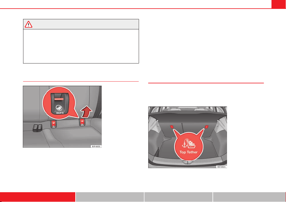
55Child safety
WARNING
● The securing rings are designed only for use with ISOFIX and Top
Tether* child seats.
● Never secure child seats that do not have the ISOFIX and Top Tether*
system, retaining belts or other objects to the securing rings – this could
result in potentially fatal injuries to the child!
● Ensure that the child seat is secured correctly using the “ISOFIX” and
Top Tether* securing rings.
ISOFIX child seat mounting system
Fig. 32 ISOFIX securing
rings
When removing or fitting the child seat, please be sure to follow
the manufacturer's instructions.
– Remove the protective caps of the “ISOFIX” rings by placing a
finger in the hole and pulling up
⇒
Fig. 32.
– Press the child seat onto the ISOFIX retaining rings until the
child seat can be heard to engage securely. If the child seat is
equipped with Toptether* anchor points, secure it to the corre-
spondent ring. Observe the manufacturer's instructions.
– Do a test by pulling both sides of the car seat to ensure that it is
properly anchored.
Child seats with the ISOFIX and Top Tether* attachment system are available
from Technical Services.
Top Tether retainer straps*
Some child restraint seats have a third Top Tether anchoring
point, apart from both “ISOFIX” anchoring points, which al-
low better child retention.
Fig. 33 Position of the
Top Tether rings on the
back of the rear seat
Safety First Operating instructions Practical Tips Technical specifications
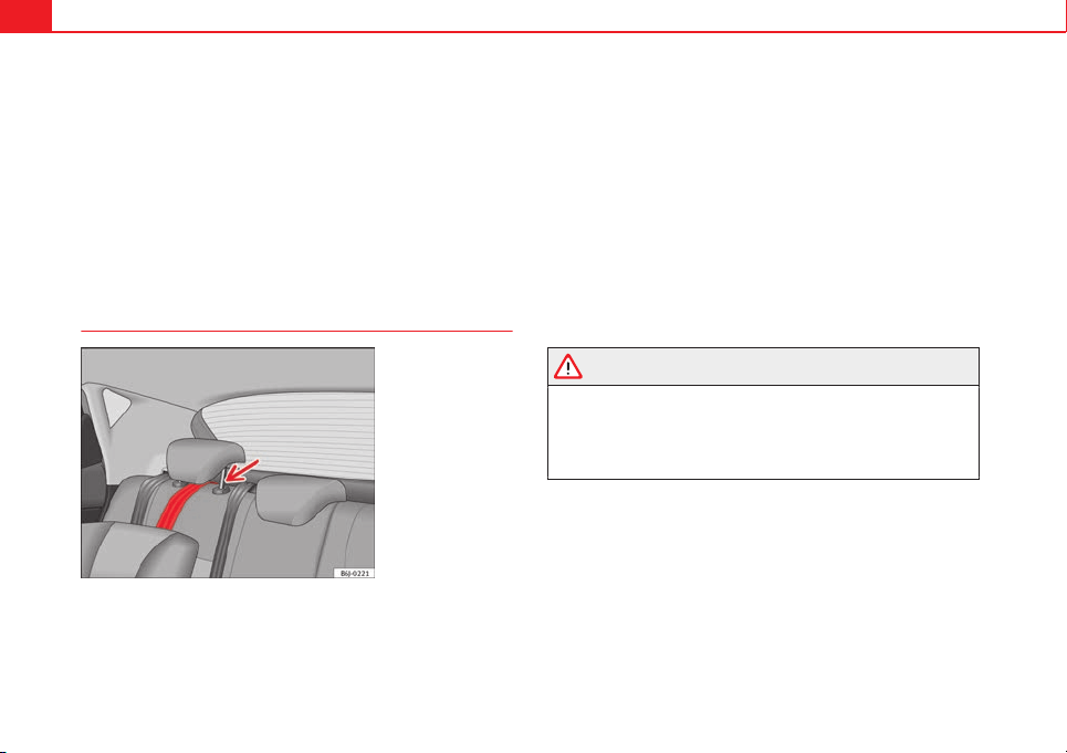
56 Child safety
Child seats with the Top Tether system come with a strap for securing the
seat to the vehicle anchor point, located at the back of the rear seat back-
rest.
The objective of the retainer strap is to reduce forward movements of the
child seat in a crash, helping reduce the risk of injuries to the head from hit-
ting the inside of the vehicle.
Using the Top Tether in rear-facing mounted seats
Currently, there are very few rear-facing child safety seats that have Top
Tether. Please carefully read and follow the seat manufacturer instructions
to learn the proper way to install the Top Tether strap.
Fitting the Top Tether child restraint to the anchoring point
Fig. 34 Retainer strap:
correct adjustment and
fitting
Securing the Top Tether child restraint to the anchor point situated
on the rear of the backrest
– Pull out the fastening belt of the child restraint seat according
to the manufacturer's instructions.
– Guide the Top Tether fastening belt under the rear seat head re-
straint ⇒ Fig. 34 (lift the head restraint where necessary).
– Slide the belt so that the Top Tether belt of the child restraint
seat is correctly secured to the anchor on the back of the rear
seat.
– Firmly tighten the Top Tether belt following the child restraint
seat manufacturer's instructions.
Releasing the retaining strap
– Release the retainer strap in line with the instructions given by
the child safety seat manufacturer.
– Push the lock and release it from the anchoring support.
WARNING
An undue installation of the safety seat will increase the risk of injury in
the event of a crash.
● Never tie the retainer strap to a hook in the luggage compartment.
● Never secure or tie luggage or other items to the lower anchorages
(ISOFIX) or the upper ones (Top Tether).

57Child safety
Safety First Operating instructions Practical Tips Technical specifications
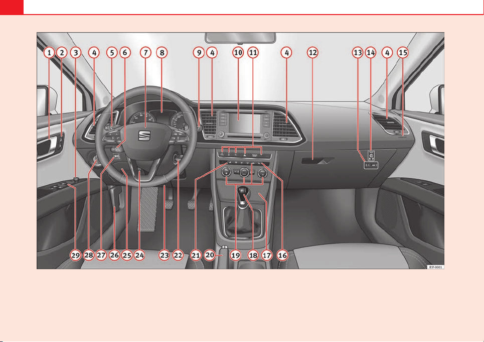
58 Controls and displays
Fig. 35 Controls and displays
59Controls and displays
Operating instructions
Controls and displays
Overview
Door handle
Central locking switch . . . . . . . . . . . . . . . . . . . . . . . . . . . . . . . . . . . . . 93
Electric control to adjust exterior mirrors . . . . . . . . . . . . . . . . . . . . 122
Air outlets . . . . . . . . . . . . . . . . . . . . . . . . . . . . . . . . . . . . . . . . . . . . . . . . 140
Control lever for:
– Turn signals and main beam headlights . . . . . . . . . . . . . . . . . 107
– Lane Assist . . . . . . . . . . . . . . . . . . . . . . . . . . . . . . . . . . . . . . . . . . . . . 168
– Main beam assist . . . . . . . . . . . . . . . . . . . . . . . . . . . . . . . . . . . . . . . 111
– Cruise control system (CCS) . . . . . . . . . . . . . . . . . . . . . . . . . . . . . 164
Depending on equipment fitted:
– Lever for cruise control . . . . . . . . . . . . . . . . . . . . . . . . . . . . . . . . . . 164
Steering wheel with horn and
– Driver airbag . . . . . . . . . . . . . . . . . . . . . . . . . . . . . . . . . . . . . . . . . . . 35
– On-board computer controls . . . . . . . . . . . . . . . . . . . . . . . . . . . . 73
– Controls for radio, telephone, navigation and speech dia-
logue system ⇒ Booklet Radio
– Paddle levers for tiptronic gearshift (automatic gearbox) . . 159
Instrument panel . . . . . . . . . . . . . . . . . . . . . . . . . . . . . . . . . . . . . . . . . . 61
Control lever for:
– Windscreen wipers and washer . . . . . . . . . . . . . . . . . . . . . . . . . . 116
– Wipe and wash system . . . . . . . . . . . . . . . . . . . . . . . . . . . . . . . . . 116
– On-board computer . . . . . . . . . . . . . . . . . . . . . . . . . . . . . . . . . . . . . 73
1
2
3
4
5
6
7
8
9
Depending on equipment fitted: Radio or display for Easy
Connect (navigation, radio, TV/video) . . . . . . . . . . . . . . . . . . . . . . 79
Depending on the equipment, buttons for:
– SEAT driving modes . . . . . . . . . . . . . . . . . . . . . . . . . . . . . . . . . . . . . 171
– Start-Stop system . . . . . . . . . . . . . . . . . . . . . . . . . . . . . . . . . . . . . . . 149
– Park assist system . . . . . . . . . . . . . . . . . . . . . . . . . . . . . . . . . . . . . . 178
– Hazard warning lights . . . . . . . . . . . . . . . . . . . . . . . . . . . . . . . . . . 110
– Airbag off display . . . . . . . . . . . . . . . . . . . . . . . . . . . . . . . . . . . . . . . 45
Glove compartment with CD changer. . . . . . . . . . . . . . . . . . . . . . . 130
Depending on the equipment:
– Multimedia interface* ⇒ Booklet Radio
– Tyre pressure switch . . . . . . . . . . . . . . . . . . . . . . . . . . . . . . . . . . . . 177
Front passenger airbag switch . . . . . . . . . . . . . . . . . . . . . . . . . . . . . 45
Front passenger airbag . . . . . . . . . . . . . . . . . . . . . . . . . . . . . . . . . . . . 35
Passenger seat heating control . . . . . . . . . . . . . . . . . . . . . . . . . . . . 126
Storage compartment
Depending on gearbox fitted, gear lever or selector lever for:
– manual gearbox . . . . . . . . . . . . . . . . . . . . . . . . . . . . . . . . . . . . . . . . 152
– automatic gearbox . . . . . . . . . . . . . . . . . . . . . . . . . . . . . . . . . . . . . . 154
Depending on the equipment, controls for:
– Heating and ventilation system or manual air conditioner . 138, 137
– Automatic air conditioner . . . . . . . . . . . . . . . . . . . . . . . . . . . . . . . 135
Parking brake . . . . . . . . . . . . . . . . . . . . . . . . . . . . . . . . . . . . . . . . . . . . . 147
Driver seat heating control . . . . . . . . . . . . . . . . . . . . . . . . . . . . . . . . . 126
10
11
12
13
14
15
16
17
18
19
20
21
Safety First Operating instructions Practical Tips Technical specifications

60 Controls and displays
Ignition lock . . . . . . . . . . . . . . . . . . . . . . . . . . . . . . . . . . . . . . . . . . . . . . 144
Knee airbag . . . . . . . . . . . . . . . . . . . . . . . . . . . . . . . . . . . . . . . . . . . . . . . 38
Adjustable steering column . . . . . . . . . . . . . . . . . . . . . . . . . . . . . . . . 143
Storage compartment
Bonnet lock release . . . . . . . . . . . . . . . . . . . . . . . . . . . . . . . . . . . . . . . 210
Headlight range control . . . . . . . . . . . . . . . . . . . . . . . . . . . . . . . . . . . 114
Light switch . . . . . . . . . . . . . . . . . . . . . . . . . . . . . . . . . . . . . . . . . . . . . . . 106
Electric windows . . . . . . . . . . . . . . . . . . . . . . . . . . . . . . . . . . . . . . . . . . 100
Note
● Some of the equipment listed in this section is only fitted on certain
models or are optional extras.
● A separate instruction manual is enclosed if the vehicle is equipped
with a factory-fitted sound system, CD changer, AUX IN connection, or navi-
gation system.
● The arrangement of switches and controls on right-hand drive models*
may be slightly different from the layout shown in ⇒ page 58. However, the
symbols used to identify the controls are the same.
22
23
24
25
26
27
28
29
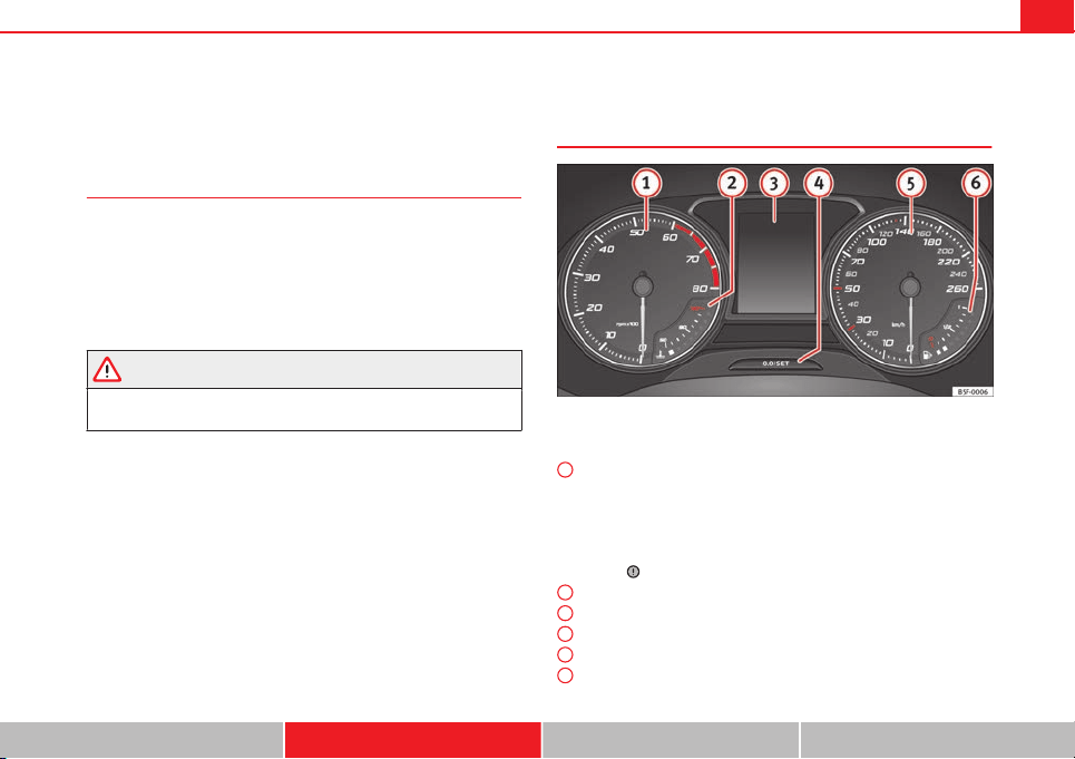
61Instruments and warning/control lamps
Instruments and warning/control lamps
Instruments
Introduction
Additional information and warnings:
● Control and warning lamps ⇒ page 69
● SEAT information system
● Easy Connect system
● Gear engaged display (automatic gearbox) ⇒ page 154.
● Instructions for inspection intervals ⇒ Booklet Maintenance Programme
WARNING
Any distraction may lead to an accident, with the risk of injury.
● Do not operate the instrument panel controls when driving.
View of instrument panel
Fig. 36 Instrument panel, on dash panel
Details of the instruments
⇒
Fig. 36:
Rev counter (with the engine running, in hundreds of revolutions per
minute).
The beginning of the red zone of the rev counter indicates the maxi-
mum speed in any gear after running-in and with the engine hot. How-
ever, it is advisable to change up a gear or move the selector lever to D
(or lift your foot off the accelerator) before the needle reaches the red
zone
⇒
.
Engine coolant temperature display
⇒
page 215.
Displays on the screen
⇒
page 62.
Adjuster button and display
⇒
page 67
Speedometer.
Fuel reserve display
⇒
page 207.
1
2
3
4
5
6
Safety First Operating instructions Practical Tips Technical specifications
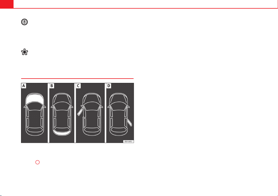
62 Instruments and warning/control lamps
CAUTION
● To prevent damage to the engine, the rev counter needle should only re-
main in the red zone for a short period of time.
● When the engine is cold, avoid high revs and heavy acceleration and do
not make the engine work hard.
For the sake of the environment
Changing up a gear in time reduces fuel consumption and noise.
Displays on screen
Fig. 37 A: bonnet open; B: rear lid open; C: front left door open; D: rear right door
open (4-door vehicles only)
A variety of information can be viewed on the instrument panel display
⇒ Fig. 36
3
, depending on the vehicle equipment:
● Bonnet, rear lid and doors open ⇒ Fig. 37.
● Information and warning texts
● Mileage
● Time
● Navigation instructions
● Outside temperature
● Compass
● Selector lever position ⇒ page 154
● Recommended gear (manual gearbox) ⇒ page 68
● Multifunction display (MFD) and menus with different setting options
⇒ page 73.
● Service interval display ⇒ page 65
● Second speed display ⇒ page 73
● Speed warning function ⇒ page 149
● Start-Stop system status display ⇒ page 149
● Identifying letters on engine (MKB)
Bonnet, rear lid and doors open
When the ignition is switched on or when driving, the bonnet, rear lid or
doors that are open will be indicated on the instrument panel display, and if
it should be the case, this will also be indicated audibly. The display may
vary according to the type of instrument panel fitted.
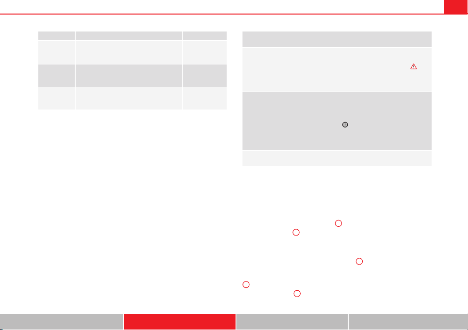
63Instruments and warning/control lamps
Illustration Key to ⇒ Fig. 37 See
A
Do not continue driving!
The bonnet is open or is not properly
closed.
⇒ page 209
B
Do not continue driving!
The rear lid is open or is not properly
closed.
⇒ page 98
C, D
Do not continue driving!
A vehicle door is open or is not properly
closed.
⇒ page 86
Warning and information texts
The system runs a check on certain components and functions when the ig-
nition is switched on and while the vehicle is moving. Faults in the opera-
tion are displayed on the screen using red and yellow symbols and messag-
es on the instrument panel display (⇒ page 69) and, in some cases, with
audible warnings. The display may vary according to the type of instrument
panel fitted.
Type of mes-
sage
Symbol
colour
Description
Priority 1
warning.
Red
Symbol flashing or lit; partly combined with
audible warnings.
Stop the vehicle! It is dangerous ⇒
!
Check the function that is faulty and repair it.
If necessary, request assistance from special-
ised personnel.
Priority 2
warning.
Yellow
Symbol flashing or lit; partly combined with
audible warnings.
A faulty function, or fluids which are below
the correct levels may cause damage to the
vehicle! ⇒
Check the faulty function as soon as possible.
If necessary, request assistance from special-
ised personnel.
Informative
text.
–
Information relating to different vehicle pro-
cesses.
Mileage
The odometer registers the total distance travelled by the car.
The odometer (trip) shows the distance travelled since the last odometer re-
set. The last digit of the trip recorder indicates distances of 100 metres or
one tenths of a mile.
● Briefly press the button ⇒ Fig. 36
4
to reset the trip recorder to 0.
● Keep the button
4
pressed for about 3 seconds and the previous value
will be displayed.
Time
● To set the time, keep the button ⇒ Fig. 36
4
pressed for more than 3
seconds to select the hour or minute display.
● To continue setting the time, press the upper or lower part of the button
4
. Hold button down to scroll through the numbers quickly.
● Press the button
4
again in order to finish setting the time.
Safety First Operating instructions Practical Tips Technical specifications
64 Instruments and warning/control lamps
The time can also be set via the
key and
Setup
function button in the
Easy Connect system ⇒ page 79.
Outside temperature display
When the outside temperature is below +4 °C (+39 °F), the symbol “ice crys-
tal” (warning of risk of freezing) is also displayed next to the temperature.
At first this symbol flashes and then it remains lit until the outside tempera-
ture rises above +6 °C (+43 °F) ⇒
.
When the vehicle is at a standstill or when travelling at very low speeds, the
temperature displayed may be higher than the true outside temperature as
a result of the heat produced by the engine.
The temperatures measured range from -40 °C to +50 °C (-40 °F to +122 °F).
Compass
With the ignition on and the navigation system on, the cardinal point corre-
sponding to the direction of travel of the vehicle is displayed on the instru-
ment panel.
Selector lever positions
The selected gear is displayed on the side of the selector lever and on the
instrument panel display. In positions D and S, and with the Tiptronic, the
corresponding gear is also displayed.
Recommended gear (manual gearbox)
The recommended gear in order to save fuel is displayed on the instrument
panel while you are driving ⇒ page 68.
Second speed display (mph or km/h)
In addition to the speedometer, the speed can also be displayed in a differ-
ent unit of measurement (in miles or in km per hour).
This option cannot be deactivated in models destined for countries in which
the second speed must always be visible.
The second speed display can be adjusted in the Easy Connect system via
the
key and the
Setup
function button ⇒ page 79.
Speed warning
When the speed setting is exceeded, this will be indicated on the instru-
ment panel display. This is very useful, for example when using winter tyres
that are not designed for driving at the maximum speed of the vehicle
⇒ page 149.
The speed warning settings can be adjusted in the Easy Connect system via
the
key and the
Setup
function button ⇒ page 79.
Start/Stop operating display
Updated information relating to the status is displayed on the instrument
panel ⇒ page 149.
Identifying letters on engine (MKB)
Hold the button ⇒ Fig. 36
4
down for more than 15 seconds to display the
identifying letters of the vehicle engine (MKB). To do this, the ignition must
be switched on and the engine switched off.
WARNING
If the warning lamps and messages are ignored, the vehicle may stall in
traffic, or may cause accidents and severe injuries.
● Never ignore the warning lamps or text messages.
● Stop the vehicle safely as soon as possible.
● A faulty vehicle represents a risk of accident for the driver and for oth-
er road users. If necessary, switch on the hazard warning lamps and put
out the warning triangle to advise other drivers.
● Park the vehicle away from the traffic, ensuring that there are no easi-
ly inflammable materials under the vehicle which could come into contact
with the exhaust system (e.g. dry grass, fuel).
65Instruments and warning/control lamps
WARNING
Although the outside temperature is above freezing, some roads and
bridges may be frozen.
● At an outside temperature of above +4 °C (+39 °F), even when the
“ice crystal” is not visible, there may still be ice on the road.
● Never rely on the outside temperature indicator!
CAUTION
Failure to heed the control lamps and text messages when they appear may
result in faults in the vehicle.
Note
● Different versions of the instrument panel are available and therefore
the versions and instructions on the display may vary. In the case of dis-
plays without warning or information texts, faults are indicated exclusively
by the warning lamps.
● Depending on the equipment, some settings and instructions can also
be carried out in the Easy Connect system.
● When several warnings are active at the same time, the symbols are
shown successively for a few seconds. The symbols will stay on until the
fault is rectified.
Service interval display
The inspection message appears on the instrument panel display
⇒ Fig. 36
4
.
SEAT makes a difference between services with engine oil change (Interval
Service) and services without engine oil change (Inspection Service). The
service interval display only gives information for service dates which in-
volve an engine oil change. The dates of the remaining services (for exam-
ple, the next Inspection Service or change of brake fluid) are listed on the
label attached to the door strut, or even in the Maintenance Programme.
In vehicles with Services established by time or mileage, the service inter-
vals are already pre-defined.
In vehicles with LongLife Service, the intervals are determined individually.
Technical progress has made it possible to considerably reduce servicing re-
quirements. The technology used by SEAT ensures that your vehicle only
has an Interval Service when it is necessary. To establish when the Interval
Service is due (max. 2 years), the vehicle's conditions of use and individual
driving styles are considered. The service pre-warning first appears 20 days
before the date established for the corresponding service. The kilometres
remaining until the next service are always rounded up to the nearest 100
km (miles) and the remaining time is given in complete days. The current
service message cannot be viewed until 500 km (miles) after the last serv-
ice. Prior to this only lines are visible on the display.
Inspection reminder
When the Service date is approaching, when the ignition is switched on a
Service reminder is displayed.
In vehicles without text messages, a spanner is displayed on the instrument
panel with a figure given in km. The number of kilometres shown is the
maximum number that may be driven until the next service. After a few sec-
onds, the display mode changes. A clock symbol appears and the number
of days until the next service appointment is due.
In vehicles with text messages, Service in --- km (miles) or --- days is dis-
played on the instrument panel.
Service due
After the service date, an audible warning is given when the ignition is
switched on and the spanner displayed on the screen flashes for a few sec-
onds . In vehicles with text messages, Service in --- km or --- days is dis-
played on the instrument panel.
Safety First Operating instructions Practical Tips Technical specifications
66 Instruments and warning/control lamps
Reading a service notification
With the ignition switched on, the engine off and the vehicle at a standstill,
the current service notification can be read:
Press and hold the button ⇒ Fig. 36
4
for more than 5 seconds to consult
the service message.
When the service date has past, a minus sign is displayed in front of the
number of kilometres or days. In vehicles with text messages the following
is displayed: Service --- km (miles) or --- days ago.
The time can also be set via the
key and
Setup
function button in the
Easy Connect system ⇒ page 79.
The service interval display is reset
If the service was not carried out by a SEAT dealership, the display can be
reset as follows:
● To reset the service interval display, turn the ignition off and press and
hold the button ⇒ Fig. 36
4
.
● Switch the ignition back on.
● Release the button
4
and press the button
4
again for the next 20
seconds.
Note
● The service message disappears after a few seconds, when the engine is
started or when
OK/RESET
is pressed on the windscreen wiper lever, or
OK
on the multifunction steering wheel.
● In vehicles with the LongLife system in which the battery has been dis-
connected for a long period of time, it is not possible to calculate the date
of the next service. Therefore the service interval display may not be correct.
In this case, please check the maximum permitted service intervals ⇒ Book-
let Maintenance Programme.
Rev counter
The rev counter indicates the number of engine revolutions
per minute.
Together with the gear-change indicator, the rev counter offers you the pos-
sibility of using the engine of your vehicle at a suitable speed.
The start of the red zone on the dial indicates the maximum engine speed
which may be used briefly when the engine is warm and after it has been
run in properly. Before reaching this range, you should change to a higher
gear for vehicles with a manual gearbox or for automatic gearboxes put the
selector lever in “D” or take your foot off the accelerator pedal.
We recommend that you avoid high revs and that you follow the recommen-
dations on the gear-change indicator. Consult the additional information in
⇒ page 68, Gear-change indicator.
CAUTION
Never allow the rev counter needle
1
⇒ Fig. 36 to go into the red zone on
the scale for more than a very brief period, otherwise, there is a risk of en-
gine damage.
For the sake of the environment
Changing up a gear early will help you to save fuel and minimise engine
noise.
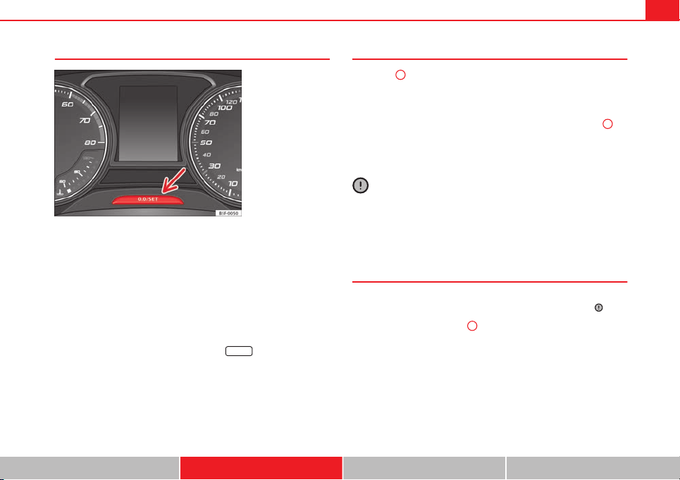
67Instruments and warning/control lamps
Trip recorder
Fig. 38 Instrument pan-
el: Odometer and reset
button
The distance covered is displayed in “kilometres” or miles “m”. It is possi-
ble to change the measurement units (kilometres “km”/miles “m”) in the
radio/Easy Connect*. Please refer to the Easy Connect* Instruction Manual
for more details.
Odometer/trip recorder
The odometer shows the total distance covered by the vehicle.
The trip recorder shows the distance that has been travelled since it was
last reset. It is used to measure short trips. The last digit of the trip recorder
indicates distances of 100 metres or one tenths of a mile.
The trip recorder can be set to zero by pressing
0.0/SET
⇒
Fig. 38.
Fault display
If there is a fault in the instrument panel, the letters DEF will appear in the
trip recorder display. Have the fault repaired immediately, as far as is possi-
ble.
Fuel level
The display
6
⇒ Fig. 36 only works when the ignition is switched on. When
the display reaches the reserve mark, the lower diode lights up in red and
the control lamp appears ⇒ page 207. When the fuel level is very low,
the lower diode flashes in red.
The distance to empty fuel level is displayed on the instrument panel
3
⇒ Fig. 36.
The capacity of the fuel tank of your vehicle is given in the Technical data
section ⇒ page 276.
CAUTION
Never run the fuel tank completely dry. An irregular fuel supply could cause
misfiring. In this way the fuel can arrive without burning the exhaust sys-
tem, which could cause the catalytic converter to overheat resulting in dam-
age.
Coolant temperature gauge
For vehicles with no coolant temperature gauge, a control lamp appears for
high coolant temperatures ⇒ page 215. Take into account the ⇒
.
The coolant temperature gauge
2
⇒ Fig. 36 only works when the ignition is
switched on. In order to avoid engine damage, please read the following
notes for the different temperature ranges.
Engine cold
If only the diodes in the lower part of the scale light up, this indicates that
the engine has not yet reached operating temperature. Avoid high revs and
heavy acceleration and do not make the engine work hard.
Safety First Operating instructions Practical Tips Technical specifications
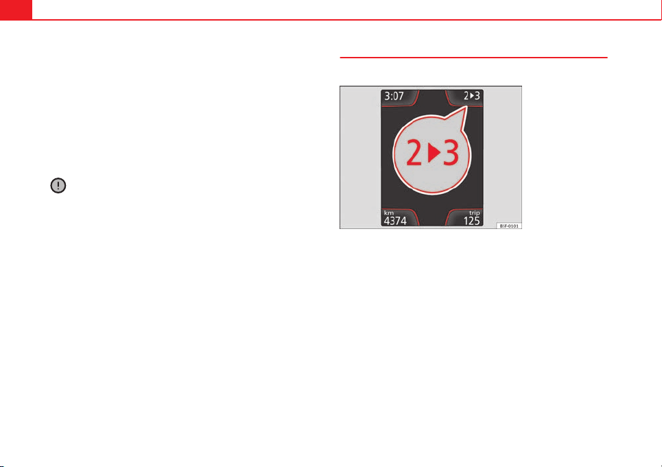
68 Instruments and warning/control lamps
Normal temperature
If in normal operations, the diodes light up until the central zone, it means
that the engine has reached operating temperature. At high outside temper-
atures and when making the engine work hard, the diodes may continue
lighting up and reach the upper zone. This is no cause for concern, provided
the control lamp does not light up on the instrument panel digital dis-
play.
Heat range
When the diodes light up in the upper area of the display and the control
lamp appears on the instrument panel display, the coolant temperature
is excessive ⇒ page 215.
CAUTION
● To ensure a long useful life for the engine, avoid high revs, driving at
high speed and making the engine work hard for approx. the first 15 mi-
nutes when the engine is cold. The phase until the engine is warm also de-
pends on the outside temperature. If necessary, use the engine oil tempera-
ture* as a guide ⇒ page 77
● Additional lights and other accessories in front of the air inlet reduce the
cooling effect of the coolant. At high outside temperatures and high engine
loads, there is a risk of the engine overheating.
● The front spoiler also ensures proper distribution of the cooling air when
the vehicle is moving. If the spoiler is damaged this can reduce the cooling
effect, which could cause the engine to overheat. Seek specialist assis-
tance.
Gear-change indicator
This additional indicator function can help to save fuel.
Fig. 39 Instrument pan-
el: Gear-change indicator
(manual gearbox)
To familiarise yourself with the gear-change indicator, we recommend driv-
ing in the normal way to start with. A gear change will be recommended if
the gear you are in is not the most economical choice.
If no gear-change is recommended, you are already in the most economical
gear.
Vehicles with a manual gearbox
The following display symbols
⇒
Fig. 39 mean:
● Change to a higher gear: The suggested gear appears to the right of
the current gear when a higher gear is recommended.
● Change to a lower gear: The suggested gear appears to the left of the
current gear when a lower gear is recommended.
The gear recommendation may occasionally skip a gear (2nd 4th).
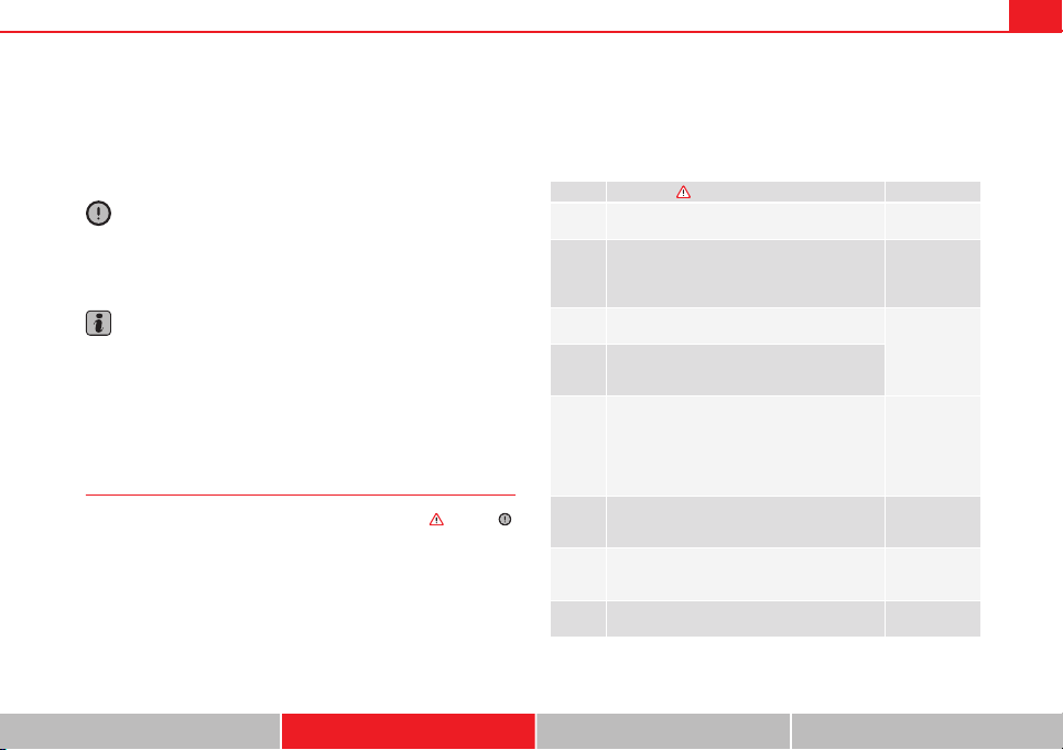
69Instruments and warning/control lamps
Vehicles with an automatic gearbox*
The display is only visible in tiptronic mode ⇒ page 159
The following display symbols mean:
● Shifting up a gear
● Shifting down a gear
CAUTION
The gear-change indicator is intended to help save fuel. It is not intended to
recommend the right gear for all driving situations. In certain situations, on-
ly the driver can choose the correct gear (for instance when overtaking, driv-
ing up a steep gradient or towing a trailer).
Note
The display disappears from the instrument panel when you press the
clutch pedal.
Control lamps
Control and warning lamps
The control and warning lamps are indicators of warnings,
⇒
, faults
⇒
or certain functions. Some control and warning lamps come on when the ig-
nition is switched on, and switch off when the engine starts running, or
while driving.
Depending on the model, additional text messages may be viewed on the
instrument panel display. These may be purely informative or they may be
advising of the need for action
⇒
page 61, Instruments.
Depending upon the equipment fitted in the vehicle, instead of a warning
lamp, sometimes a symbol may be displayed on the instrument panel.
When certain control and warning lamps are lit, an audible warning is also
heard.
Red symbols
Symbol Meaning ⇒ See
Central warning lamp: additional information
on the instrument panel display
–
Symbol on the instrument panel display:
Do not continue driving!
With the corresponding indication: door(s), rear
lid or bonnet open or not properly closed.
⇒ page 86
⇒ page 98
⇒ page 209
Parking brake on.
⇒ page 147
⇒ page 185
Do not continue driving!
The brake fluid level is too low or there is a fault
in the brake system.
Lit up on instrument panel display:
a)
Do not continue driving!
Engine coolant level too low, coolant tempera-
ture too high
Flashing on the instrument panel display:
a)
Fault in the engine coolant system.
⇒ page 215
On the instrument panel display:
a)
Do not continue driving!
Engine oil pressure too low.
⇒ page 211
Lit up or flashing:
Do not continue driving!
Fault in the steering.
⇒ page 186
Driver or passenger has not fastened seat belt. ⇒ page 19
Safety First Operating instructions Practical Tips Technical specifications
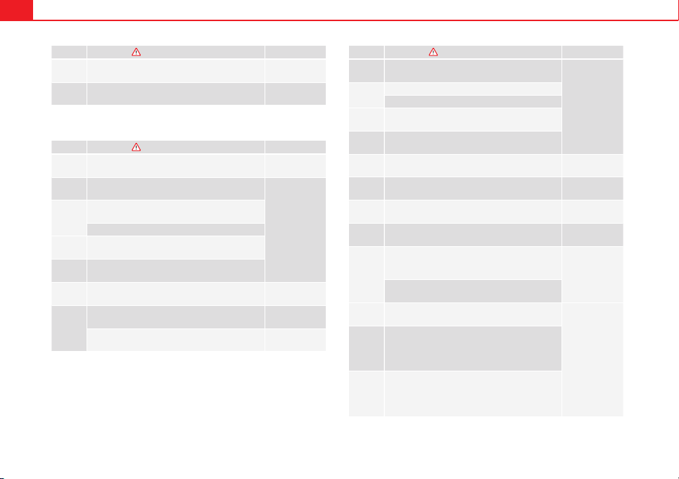
70 Instruments and warning/control lamps
Symbol Meaning ⇒ See
Use the foot brake!
On the instrument panel display:
a)
Fault in the battery.
⇒ page 217
a)
Colour presentation on instrument panel with colour display.
Yellow symbols
Symbol Meaning ⇒ See
Central warning lamp: additional information
on the instrument panel display
–
Front brake pads worn.
⇒ page 183
lights: Fault in the ESC, or disconnection
caused by the system.
flashes: ESC or ASR activated.
ASR manually deactivated.
ABS faulty or does not work.
Rear fog light switched on. ⇒ page 106
On the instrument panel display:
a)
Driving light totally or partially faulty.
⇒ page 252
On the instrument panel display:
a)
Fault in the cornering light system.
⇒ page 106
Symbol Meaning ⇒ See
Lights up or flashes: Fault in the emission con-
trol system.
⇒ page 190
lights: pre-ignition of diesel engine.
flashes: Fault in engine management.
Fault in engine management.
On the instrument panel display:
a)
Diesel particulate filter blocked.
Lights up or flashes: Fault in the steering sys-
tem.
⇒ page 143
Tyre pressure too low, or fault in the tyre pres-
sure monitoring system.
⇒ page 175
On the instrument panel display:
a)
Level of windscreen washer fluid too low.
⇒ page 116
Fuel tank almost empty. ⇒ page 207
Flashing on the instrument panel display:
a)
Fault in the oil level detection. Control manual-
ly.
⇒ page 211
Lit up on the instrument panel display:
a)
Engine oil level insufficient.
Fault in airbag system and seat belt tensioners.
⇒ page 30
Front passenger front airbag is off (PASSENGER
AIRBAG ).
Front passenger front airbag is on (PASSENGER
AIRBAG ).

71Instruments and warning/control lamps
Symbol Meaning ⇒ See
Lane Assist is switched on, but not active. ⇒ page 168
On the instrument panel display:
a)
Fault in the gearbox.
⇒ page 162
a)
Colour presentation on instrument panel with colour display.
Other control lamps
Symbol Meaning ⇒ See
Left or right turn signal. ⇒ page 106
Hazard warning lights on. ⇒ page 110
Trailer turn signals ⇒ page 194
lights: Press the foot brake!
flashes: The selector lever locking button has
not engaged.
⇒ page 154
The vehicle is stopped by engine braking.
lights: Cruise control operating.
⇒ page 164
lights: Speed limiter switched on and active.
flashes: The speed set by the speed limiter has
been exceeded.
Lane Assist is switched on and active. ⇒ page 168
Main beam on or flasher on.
⇒ page 106
On the instrument panel display:
Light Assist switched on.
On the instrument panel display:
Immobiliser active.
Symbol Meaning ⇒ See
On the instrument panel display:
Service interval display.
⇒ page 65
On the instrument panel display:
Mobile telephone is connected via Bluetooth to
the original telephone device.
⇒ Book-
let Bluetooth
System
On the instrument panel display:
Mobile telephone battery charge meter. Availa-
ble only for pre-installed factory-fitted devices.
On the instrument panel display:
Ice warning. The outside temperature is lower
than +4 °C (+39 °F).
⇒ page 64
On the instrument panel display:
Start-Stop system active.
⇒ page 149
On the instrument panel display:
Start-Stop system not available.
On the instrument panel display:
Engine running.
WARNING
If the warning lamps and messages are ignored, the vehicle may stall in
traffic, or may cause accidents and severe injuries.
● Never ignore the warning lamps or text messages.
● Stop the vehicle safely as soon as possible.
● Park the vehicle away from the traffic, ensuring that there are no easi-
ly inflammable materials under the vehicle which could come into contact
with the exhaust system (e.g. dry grass, fuel).
● A faulty vehicle represents a risk of accident for the driver and for oth-
er road users. If necessary, switch on the hazard warning lamps and put
out the warning triangle to advise other drivers.
Safety First Operating instructions Practical Tips Technical specifications
72 Instruments and warning/control lamps
WARNING (Continued)
● Before opening the bonnet, switch off the engine and allow it to cool.
● In any vehicle, the engine compartment is a hazardous area and could
cause severe injuries ⇒ page 209.
CAUTION
Failure to heed the control lamps and text messages when they appear may
result in faults in the vehicle.
73Driver information system
Driver information system
Information system
Introduction
With the ignition switched on, it is possible to read the different functions of
the display by scrolling through the menus.
In vehicles with multifunction steering wheel, the multifunction display can
only be operated with the multifunction steering wheel buttons.
The number of menus displayed on the instrument panel will vary according
to the vehicle electronics and equipment.
A specialised workshop will be able to programme or modify additional
functions, according to the vehicle equipment. SEAT recommends visiting a
SEAT Official Service.
Some menu options can only be read when the vehicle is at a standstill.
As long as a priority 1 warning is displayed, it will not be possible to read
the menus. Some warning messages can be confirmed and made to disap-
pear with the windscreen wiper lever button or the multifunction steering
wheel button.
Additional information and warnings:
● Easy Connect system ⇒ page 79
● Driver assistance systems ⇒ page 164
● Radio or navigation system ⇒ Booklet Radio or ⇒ Booklet Navigation
system
WARNING
Any distraction may lead to an accident, with the risk of injury.
● Do not read the instrument panel display menus when driving.
Overview of the menu structure
Driving data ⇒ page 75
■
Vehicle status
■
MFD from departure
■
MFD from refuelling
■
MFD total calculation
Assist systems ⇒ table on page 75
■
Activate/deactivate Lane Assist
■
Reverse (optional)
Navigation ⇒ Booklet Navigation system
Audio ⇒ Booklet Radio or ⇒ Booklet Navigation system
Telephone ⇒ Booklet Bluetooth system
Vehicle ⇒ table on page 75
Safety First Operating instructions Practical Tips Technical specifications
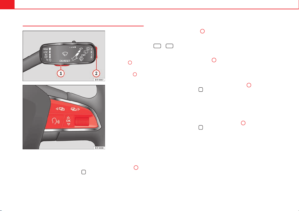
74 Driver information system
Operating the instrument panel menus
Fig. 40 Vehicles without
multifunction steering
wheel: Button
1
on the
windscreen wiper lever to
confirm the menu options
and rocker switch
2
to
change menu
Fig. 41 Right side of
multifunction steering
wheel: buttons to access
the instrument panel me-
nus
Enabling the main menu
● Switch the ignition on.
● If a message or vehicle pictogram appears, press button ⇒ Fig. 40
1
on
the windscreen wiper lever or button
on the multifunction steering wheel
⇒ Fig. 41.
● If managed from the windscreen wiper lever: To display the main menu
⇒ page 75 or to return to the main menu from another menu, hold the
rocker switch down ⇒ Fig. 40
2
.
● If managed from the multifunction steering wheel: the main menu list is
not displayed. To go from point to point in the main menu, press button
or
several times ⇒ Fig. 41.
Select a submenu
● Press the rocker switch ⇒ Fig. 40
2
on the windscreen wiper lever up or
down or turn the thumbwheel of the multifunction steering wheel ⇒ Fig. 41
until the desired option appears marked on the menu.
● The selected option is displayed between two horizontal lines. In addi-
tion, a triangle is displayed on the right: .
● To consult the submenu option, press button ⇒ Fig. 40
1
on the wind-
screen wiper lever or button
on the multifunction steering wheel
⇒ Fig. 41.
Making changes according to the menu
● With the rocker switch on the windscreen wiper lever or the thumbwheel
of the multifunction steering wheel, make the desired changes. To increase
or decrease the values more quickly, turn the thumbwheel faster.
● Mark or confirm the selection with button ⇒ Fig. 40
1
on the wind-
screen wiper lever or button
on the multifunction steering wheel
⇒ Fig. 41.
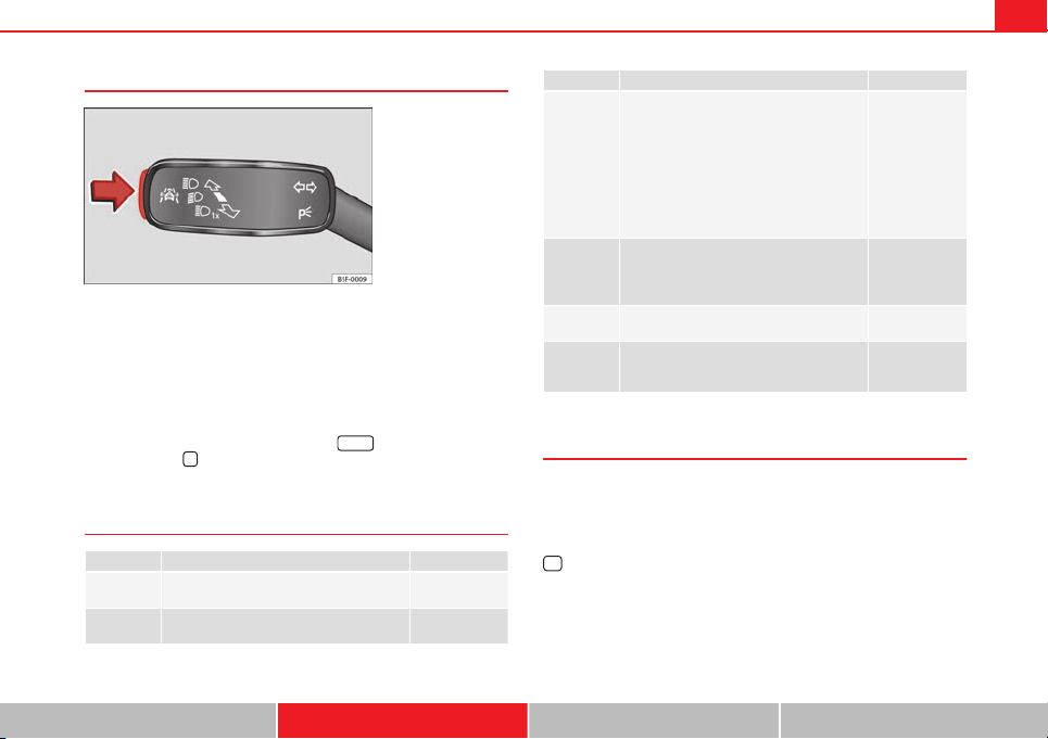
75Driver information system
Button for the driving assistance systems
Fig. 42 On the turn sig-
nal and main beam head-
light lever: button for the
driving assistance sys-
tems
With the turn signal and main beam headlight lever button, you can activate
or deactivate the driver assistance systems Assist systems ⇒ page 164.
Activate or deactivate a driver assistance system
● Briefly press the button ⇒ Fig. 42 in the direction of the arrow to open
the menu Assist systems.
● Select the driver assistance system and activate or deactivate it
⇒ page 74. A mark indicates that driver assistance system is switched on.
● Mark or confirm the selection with button
on the windscreen wip-
er lever or button
on the multifunction steering wheel ⇒ page 74.
Menu
Menu Function See
Driving data
Information and possible configurations of
the multifunction display (MFD).
⇒ page 75
⇒ page 79
Assist sys-
tems
Information and possible configurations of
the driver assistance systems.
⇒ page 79
Menu Function See
Navigation
Information instructions from the activated
navigation system: When a route guidance
is activated, the turning arrows and prox-
imity bars are displayed. The appearance is
similar to the Easy Connect system.
If the route guidance is not activated, the
direction of travel (compass) and the name
of the street along which you are driving
are shown.
⇒ Booklet Navi-
gation system
Audio
Station display on the radio.
Track name on the CD.
Track name in Media mode.
⇒ Booklet Radio
or
⇒ Booklet Navi-
gation system
Telephone
Information and possible configurations of
the mobile phone preinstallation.
⇒ Booklet Blue-
tooth System
Vehicle sta-
tus
Display of the current warning or informa-
tion texts and other system components,
depending on the equipment
⇒ page 79
Driving data
The MFD (multifunction display) shows different values for the journey and
the consumption.
Changing between display modes on the MFD
● In vehicles without multifunction steering wheel: Press the rocker switch
on the windscreen wiper lever ⇒ Fig. 40.
● Vehicles with a multifunction steering wheel: turn the thumbwheel.
Safety First Operating instructions Practical Tips Technical specifications
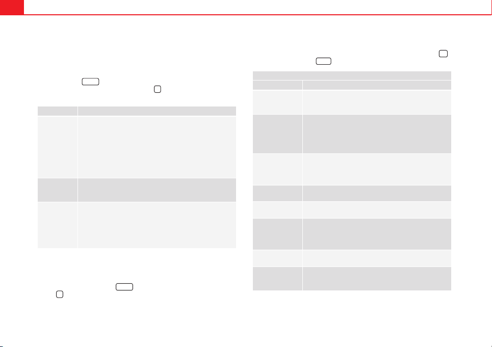
76 Driver information system
Multifunction display memory
The multifunction display is equipped with three memories that work auto-
matically: MFD from departure, MFD from refuelling, MFD total calculation.
On the screen display, you can read which memory is currently displayed.
To change between memories with the ignition on and the memory shown,
press the button
on the windscreen wiper lever or you can also
change between memories using the button
on the multifunction steer-
ing wheel.
Menu Function
MFD from de-
parture
Display and storage of the values for the journey and the
consumption from when the ignition is switched on to
when it is switched off.
If the journey is continued in less than 2 hours after the ig-
nition is switched off, the new data is added to the data al-
ready stored in the memory. The memory will automatically
be deleted if the journey is interrupted for more than two
hours.
MFD from re-
fuelling
Display and storage of the values for the journey and the
consumption. By refuelling, the memory will be erased au-
tomatically.
MFD total cal-
culation
The memory records the values for a specific number of
partial trips, up to a total of 19 hours and 59 minutes or 99
hours and 59 minutes, or 1999.9 km (or miles) or 9999 km
(or miles), depending on the model of instrument panel.
On reaching either of these limits
a)
, the memory is auto-
matically erased and starts to count from 0 again.
a)
It varies according to the type of instrument panel fitted.
Erasing a memory manually
● Select the memory that you wish to erase.
● Press and hold the button
on the windscreen wiper lever or the
button
on the multifunction steering wheel for about 2 seconds.
Personalising the displays
In the Easy Connect system you can adjust which of the possible displays of
the MFD can be shown on the instrument panel display with the button
and the function button
Setup
⇒ page 79.
Displays
Menu Function
Current fuel con-
sumption
The current fuel consumption display operates through-
out the journey, in litres/100 km; and with the engine
running and the vehicle stopped, in litres/hour.
Average fuel con-
sumption
After turning on the ignition, average fuel consumption
in litres/100 km will be shown after travelling approxi-
mately 100 metres. Otherwise horizontal lines are dis-
played. The value shown is updated approximately ev-
ery 5 seconds.
Operating range
Approximate distance in km that can still be travelled
with the fuel remaining in the tank, assuming the same
style of driving is maintained. This is calculated using
the current fuel consumption.
Journey duration
This indicates the hours (h) and minutes (min) since
the ignition was switched on.
Distance covered
Distance covered in km (m) after switching on the igni-
tion.
Average speed
The average speed will be shown after a distance of ap-
proximately 100 metres has been travelled. Otherwise
horizontal lines are displayed. The value shown is up-
dated approximately every 5 seconds.
Digital display of
speed
Current speed displayed in digital format.
Speed warning at
--- km/h or Speed
warning at --- mph
If the stored speed is exceeded (between 30 - 250 km/
h, or 1 - 155 mph), an audible warning is given togeth-
er with a visual warning.
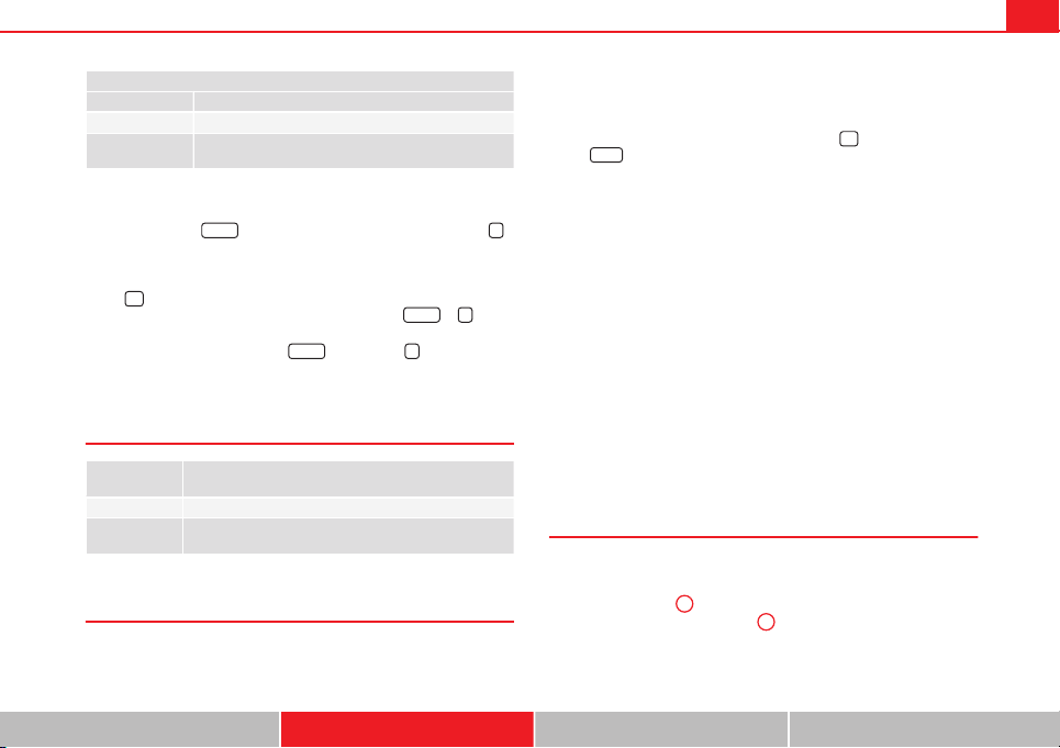
77Driver information system
Displays
Menu Function
Oil temperature Updated engine oil temperature digital display
Coolant tempera-
ture gauge
Digital display of the current temperature of the liquid
coolant.
Storing a speed for the speed warning
● Select the display Speed warning at --- km/h (--- mph)
● Press the button
on the windscreen wiper lever or the button
on the multifunction steering wheel to store the current speed and activate
the warning.
● If necessary, adjust the desired speed within 5 seconds using the rocker
switch
on the windscreen wiper lever or by turning the thumbwheel on
the multifunction steering wheel. Next, press the button
or
again
or wait several seconds. The speed is stored and the warning activated.
● To deactivate it press the button
or the button
. The stored
speed is deleted.
Assist systems submenu
Assist systems
menu
Function
Lane Assist* Switching the Lane Assist system on or off ⇒ page 170.
Tiredness detec-
tion*
Switching the tiredness detection on or off (pause recom-
mendation) ⇒ page 173.
Personal convenience settings
When two people use a vehicle, SEAT recommends that each person always
uses their own remote control key. When the ignition is switched off, or the
vehicle is locked, the convenience settings are stored and allocated to the
vehicle key ⇒ page 73.
The values of the personalised convenience settings are allocated to the ve-
hicle key in the Easy Connect system via the button
and the function
button
Setup
⇒ page 79:
Vehicle settings menu
■
Time
■
Language
■
Units
Convenience settings menu
■
Door unlock (individual opening, Auto Lock)
■
Convenience handling of windows
■
Rear vision mirror adjustment
Light settings menu
■
Coming home and leaving home
■
Footwell light
■
Convenience turn signals
The stored settings are automatically activated, at the latest when the igni-
tion is switched on.
Engine oil temperature display
Vehicles without multifunction steering wheel
– To display the temperature of the engine oil, press the rocker
switch ⇒ Fig. 40
2
until the main menu appears. Enter into
Journey data. With the button
2
move to the oil temperature
gauge.
Safety First Operating instructions Practical Tips Technical specifications
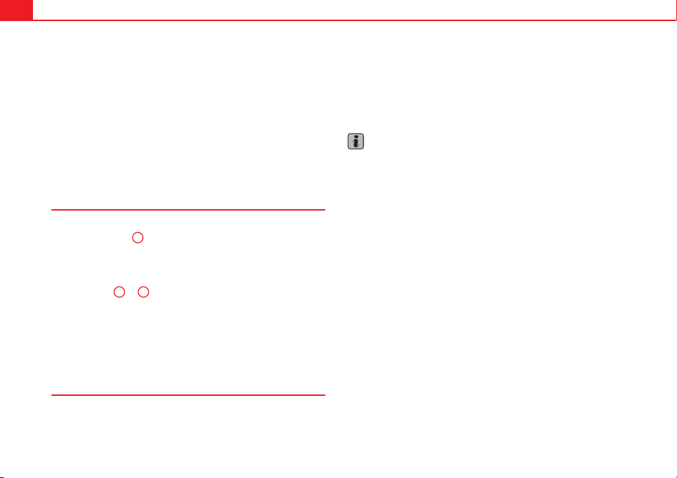
78 Driver information system
Vehicles with multifunction steering wheel
– To display the engine oil temperature, enter the submenu Jour-
ney data and turn the thumbwheel until the oil temperature dis-
play appears.
The engine reaches its operating temperature when in normal driving condi-
tions, the oil temperature is between 80 °C (180 °F) and 120 °C (250 °F). If
the engine is required to work hard and the outside temperature is high, the
engine oil temperature can increase. This does not present any problem as
long as the warning lamps ⇒ page 69 or ⇒ page 70 do not appear on
the display.
Additional electrical appliances
– Operation with the windscreen wiper lever*: Press the rocker
switch ⇒ Fig. 40
2
until the main menu appears. Enter into the
section Journey data. With the rocker switch, move to the display
Convenience appliances.
– Operation with the multifunction steering wheel*: Move with
the buttons
1
or
2
to Journey data and enter with OK. Turn the
thumbwheel to the right until the Convenience appliances dis-
play appears.
In addition, a scale will inform you of the current sum of all the additional
appliances.
Saving tips
Tips on how to save fuel will be displayed in certain conditions that
contribute to increased consumption. Following these tips could
reduce the fuel consumption of your vehicle. The displays appear
automatically and will only be shown with the efficiency pro-
gramme. After a time, the saving tips will disappear automatically.
– If you wish to hide a saving tip immediately after it appears,
press any button on the windscreen wiper lever*/multifunction
steering wheel*.
Note
● If you hide a saving tip, it will reappear after you switch the ignition on
again.
● The saving tips do not appear in all situations, but rather with a large
separation of time.
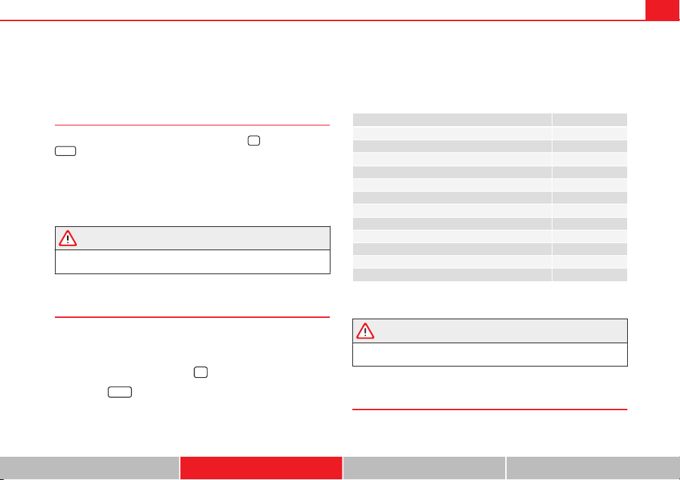
79Introduction to the Easy Connect system*
Introduction to the Easy Connect system*
System settings (CAR)*
Introduction
To select the settings menus, press the Easy Connect
button and the
Setup
function button.
The actual number of menus available and the name of the various options
in these menus will depend on the vehicle’s electronics and equipment.
Additional information and warnings:
● Driver assistance systems ⇒ page 164
WARNING
Any distraction may lead to an accident, with the risk of injury. Operating
the Easy Connect system while driving could distract you from traffic.
CAR menu (Setup) settings
– Switch the ignition on.
– Switch on the Easy Connect system.
– Press the Easy Connect button
.
– Press the
Setup
function button to open the main Vehicle set-
tings menu.
Pressing the menu button will always take you to the last menu
used.
Function buttons in the vehicle’s settings menu Page
ESC system ⇒ page 79
Tyres ⇒ page 80
Driver assistance ⇒ page 80
Parking and manoeuvring ⇒ page 81
Vehicle lights ⇒ page 81
Rear vision mirrors and windscreen wipers ⇒ page 82
Opening and closing ⇒ page 82
Multifunction display ⇒ page 83
Date and time ⇒ page 84
Units ⇒ page 84
Service ⇒ page 85
Factory settings ⇒ page 85
Any changes made using the settings menus are automatically saved on
closing those menus.
WARNING
Any distraction may lead to an accident, with the risk of injury. Operating
the Easy Connect system while driving could distract you from traffic.
ESC System menu
– Switch the ignition on.
Safety First Operating instructions Practical Tips Technical specifications
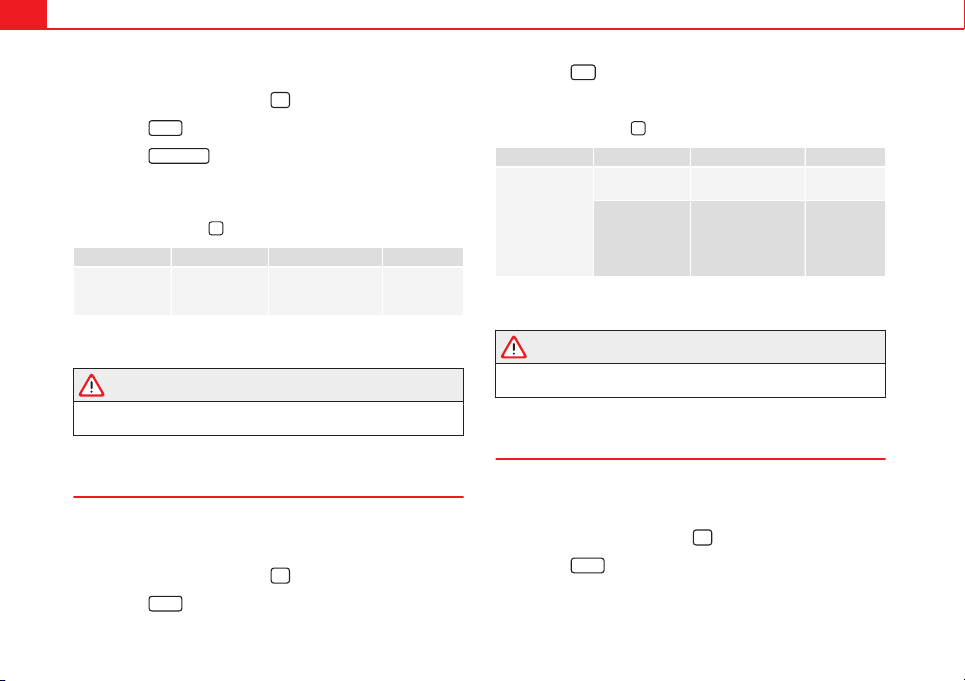
80 Introduction to the Easy Connect system*
– Switch on the Easy Connect system.
– Press the Easy Connect button
.
– Press the
Setup
function button.
– Press the
ESC System
function button to make changes to the
Electronic Stability Programme (ESC).
When the menu appears, choose the desired option.
Pressing the menu button
will always take you to the last menu used.
Menu Submenu Possible setting Description
Vehicle settings –
Activation of the
Electronic Stability
Programme (ESC)
⇒ page 183
Any changes made using the settings menus are automatically saved on
closing those menus.
WARNING
Any distraction may lead to an accident, with the risk of injury. Operating
the Easy Connect system while driving could distract you from traffic.
Tyre Settings menu
– Switch the ignition on.
– Switch on the Easy Connect system.
– Press the Easy Connect button
.
– Press the
Setup
function button.
– Press the
Tyre
button to open the Tyre settings menu.
When the function button check box is activated , the function is active.
Pressing the menu button
will always take you to the last menu used.
Menu Submenu Possible setting Description
Tyre settings
Tyre pressure
monitoring
Tyre pressure storing
(Calibration)
⇒ page 175
Winter tyres
Speed warning acti-
vation and deactiva-
tion
Change the speed
warning value
⇒ page 149
Any changes made using the settings menus are automatically saved on
closing those menus.
WARNING
Any distraction may lead to an accident, with the risk of injury. Operating
the Easy Connect system while driving could distract you from traffic.
Driver Assistance settings menu
– Switch the ignition on.
– Switch on the Easy Connect system.
– Press the Easy Connect button
.
– Press the
Setup
function button.
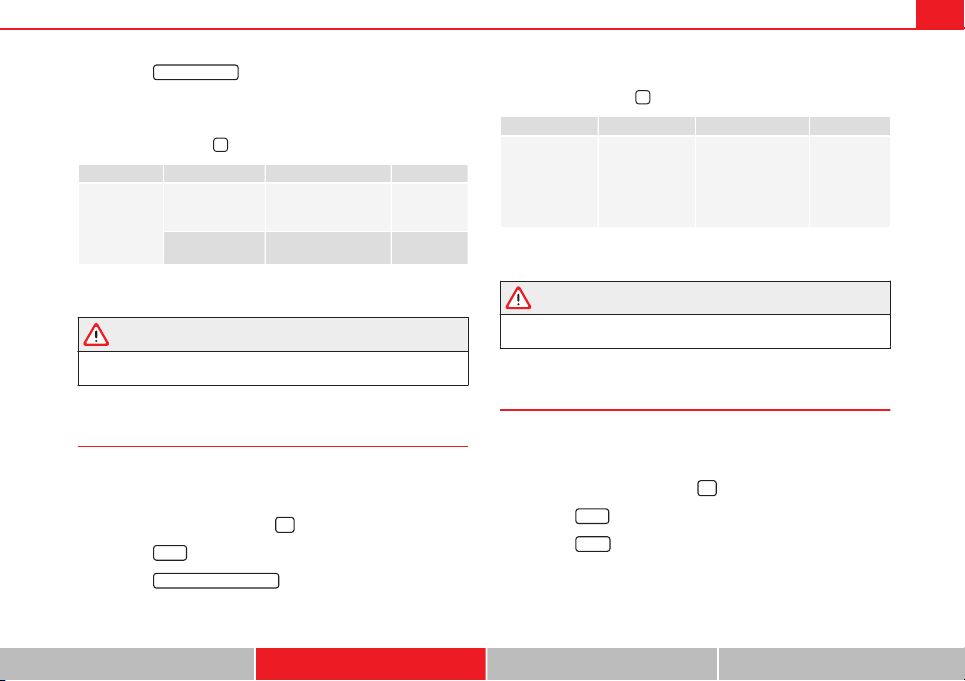
81Introduction to the Easy Connect system*
– Press the
Driver assistance
function button to open the Driver as-
sistance settings menu.
When the function button check box is activated , the function is active.
Pressing the menu button
will always take you to the last menu used.
Menu Submenu Possible setting Description
Driver Assis-
tance settings
Lane Assist (sys-
tem warning you if
you leave the lane)
Lane Centring Assist ⇒ page 168
Tiredness detec-
tion
Activation ⇒ page 173
Any changes made using the settings menus are automatically saved on
closing those menus.
WARNING
Any distraction may lead to an accident, with the risk of injury. Operating
the Easy Connect system while driving could distract you from traffic.
Parking and Manoeuvring Settings menu
– Switch the ignition on.
– Switch on the Easy Connect system.
– Press the Easy Connect button
.
– Press the
Setup
function button.
– Press the
Parking and manoeuvring
button to open the Parking and
manoeuvring settings menu.
When the function button check box is activated , the function is active.
Pressing the menu button
will always take you to the last menu used.
Menu Submenu Possible setting Description
Parking and Ma-
noeuvring set-
tings
ParkPilot
Automatically acti-
vate, front volume,
front sound settings,
rear volume, rear
sound settings, ad-
just volume.
⇒ page 178
Any changes made using the settings menus are automatically saved on
closing those menus.
WARNING
Any distraction may lead to an accident, with the risk of injury. Operating
the Easy Connect system while driving could distract you from traffic.
Light Settings menu
– Switch the ignition on.
– Switch on the Easy Connect system.
– Press the Easy Connect button
.
– Press the
Setup
function button.
– Press the
Lights
function button to open the Light settings
menu.
When the function button check box is activated , the function is active.
Safety First Operating instructions Practical Tips Technical specifications
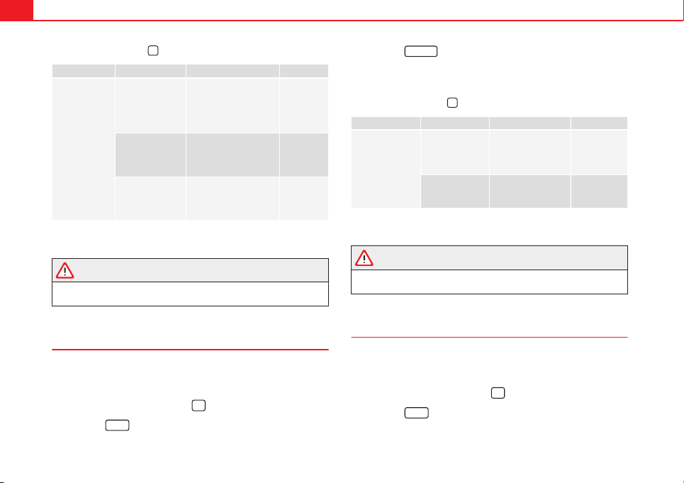
82 Introduction to the Easy Connect system*
Pressing the menu button
will always take you to the last menu used.
Menu Submenu Possible setting Description
Light settings
Light Assist
Light Assist, sensitivity,
automatic light when
raining, daytime driving
lights, convenience turn
signals.
⇒ page
111
Vehicle interior
lighting
Instrument and control
lighting, ambient door
lighting, footwell light-
ing.
⇒ page
114
"Coming
home"/"Leaving
home" function
Start time for “Coming
home” function, start
time for “Leaving
home” function.
⇒ page
113
Any changes made using the settings menus are automatically saved on
closing those menus.
WARNING
Any distraction may lead to an accident, with the risk of injury. Operating
the Easy Connect system while driving could distract you from traffic.
Rear Vision Mirror and Windscreen Wipers Settings menu
– Switch the ignition on.
– Switch on the Easy Connect system.
– Press the Easy Connect button
.
– Press the
Setup
function button.
– Press the
Visibility
function button to open the Visibility settings
menu.
When the function button check box is activated , the function is active.
Pressing the menu button
will always take you to the last menu used.
Menu Submenu Possible setting Description
Visibility settings
Rear vision mir-
rors
Synchronised regu-
lation, lower when
reversing, fold in af-
ter parking.
⇒ page 122
Windscreen wip-
ers
Automatic wind-
screen wipers, wipe
when reversing.
⇒ page 116
Any changes made using the settings menus are automatically saved on
closing those menus.
WARNING
Any distraction may lead to an accident, with the risk of injury. Operating
the Easy Connect system while driving could distract you from traffic.
Opening and Closing Settings menu
– Switch the ignition on.
– Switch on the Easy Connect system.
– Press the Easy Connect button
.
– Press the
Setup
function button.
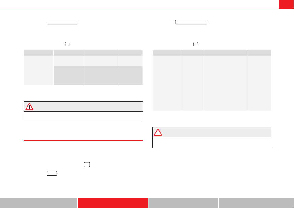
83Introduction to the Easy Connect system*
– Press the
Opening and closing
function button to open the Open-
ing and closing settings menu.
When the function button check box is activated , the function is active.
Pressing the menu button
will always take you to the last menu used.
Menu Submenu Possible setting Description
Opening and
Closing settings
Radio-operated
remote control
Convenience open
function.
⇒ page 91
Central locking
Unlocking doors, au-
tomatic locking/un-
locking, audible
confirmation.
⇒ page 86
Any changes made using the settings menus are automatically saved on
closing those menus.
WARNING
Any distraction may lead to an accident, with the risk of injury. Operating
the Easy Connect system while driving could distract you from traffic.
Multifunction Display settings menu
– Switch the ignition on.
– Switch on the Easy Connect system.
– Press the Easy Connect button
.
– Press the
Setup
function button.
– Press the
Multifunction Display
function button to open the Multi-
function Display settings menu.
When the function button check box is activated , the function is active.
Pressing the menu button
will always take you to the last menu used.
Menu Submenu Possible setting Description
Multifunction dis-
play settings
–
Current consumption, aver-
age consumption, volume
to fill up, convenience
equipments, ECOAdvice,
duration of journey, dis-
tance travelled, digital
average speed display,
speed, speeding warning,
oil temperature, coolant
temperature, restore data
“from start”, restore “total
calculation” data.
⇒ page 73
Any changes made using the settings menus are automatically saved on
closing those menus.
WARNING
Any distraction may lead to an accident, with the risk of injury. Operating
the Easy Connect system while driving could distract you from traffic.
Safety First Operating instructions Practical Tips Technical specifications
84 Introduction to the Easy Connect system*
Date and Time settings menu
The menu options will vary depending on the sound system
fitted in the vehicle.
– Switch the ignition on.
– Switch on the Easy Connect system.
– Press the Easy Connect button
.
– Press the
Setup
function button.
– Press the
Date and time
function button to open the Date and
time settings menu.
When the function button check box is activated , the function is active.
Pressing the menu button
will always take you to the last menu used.
Menu
Submenu Possible setting Description
Date and time set-
tings
–
Time source, set the
time, automatic summer
time setting, select time
zone, time format, set
the date, date format.
–
Any changes made using the settings menus are automatically saved on
closing those menus.
WARNING
Any distraction may lead to an accident, with the risk of injury. Operating
the Easy Connect system while driving could distract you from traffic.
Units Settings menu
– Switch the ignition on.
– Switch on the Easy Connect system.
– Press the Easy Connect button
.
– Press the
Setup
function button.
– Press the
Measurement Units
function button to open the Meas-
urement units settings menu.
When the menu appears, choose the desired option.
Pressing the menu button
will always take you to the last menu used.
Menu Submenu Possible setting Description
Measurements
unit settings
Distance
a)
–
Speed
Temperature
Volume
Fuel consumption
a)
Data not available at the time of going to print
Any changes made using the settings menus are automatically saved on
closing those menus.
WARNING
Any distraction may lead to an accident, with the risk of injury. Operating
the Easy Connect system while driving could distract you from traffic.
85Introduction to the Easy Connect system*
Service information
– Switch the ignition on.
– Switch on the Easy Connect system.
– Press the Easy Connect button
.
– Press the
Setup
function button.
– Press the
Service
function button to display the information
about service inspections.
Pressing the menu button
will always take you to the last menu used.
Menu Submenu Possible setting Description
Service –
Chassis number,
date of next SEAT
service inspection,
date of next oil
change service.
⇒ page 61
WARNING
Any distraction may lead to an accident, with the risk of injury. Operating
the Easy Connect system while driving could distract you from traffic.
Restoring default settings
– Switch the ignition on.
– Switch on the Easy Connect system.
– Press the Easy Connect button
.
– Press the
Setup
function button.
– Press the
Factory settings
function button to open the Factory set-
tings menu.
Pressing the menu button
will always take you to the last menu used.
Menu Submenu Possible setting Description
Factory settings –
All settings, driver
assistance, parking
and manoeuvring,
lights, rear vision
mirrors and wind-
screen wipers, open-
ing and closing,
multifunction dis-
play.
–
Any changes made using the settings menus are automatically saved on
closing those menus.
WARNING
Any distraction may lead to an accident, with the risk of injury. Operating
the Easy Connect system while driving could distract you from traffic.
Safety First Operating instructions Practical Tips Technical specifications

86 Opening and closing
Opening and closing
Central locking system
Description
The vehicle can be locked and unlocked via the central locking system.
There are several methods, depending on the vehicle equipment:
● key with remote control ⇒ page 91,
● lock on driver door (emergency opening ⇒ page 97) or
● interior central locking switch ⇒ page 93.
Unlocking one side of the vehicle only
When you lock the vehicle with the key, the doors and the rear lid are
locked. When you open the door, you can either unlock only the driver door,
or all the vehicle doors. To select the required option, use Easy Connect*
⇒ page 92.
Central locking (Auto Lock)
The Auto Lock function locks the doors and the rear lid when the vehicle ex-
ceeds a speed of about 15 km/h (10 mph).
The vehicle is unlocked again when the ignition key is removed. Alternative-
ly, the vehicle can also be unlocked via the central locking switch or by pull-
ing one of the inside door handles. The Auto Lock function can be switched
on and off on the sound system or on the Easy Connect* system
⇒ page 92.
In the event of an accident in which the airbags inflate, the doors will be au-
tomatically unlocked to facilitate access and assistance.
Anti-theft security system (Safelock)
1)
The following message is displayed on the instrument panel to remind the
driver that when the vehicle is closed from the outside, the anti-theft securi-
ty system is switched on. Do not forget the Safelock. Please see Instruction
Manual. The vehicle cannot be opened from inside. This makes it more diffi-
cult for unauthorised persons to break into the vehicle ⇒ .
The anti-theft security system can be switched off each time the vehicle is
locked:
● Turn the key a second time to the lock position, in the door lock, for the
next two seconds. If necessary, remove the protective cover on the driver
door handle ⇒ page 97. or
● Press
on the remote control key for a second time for the following 2
seconds.
The flashing frequency of the diode in the door sill immediately confirms
the process. Initially, the diode flashes in a fast sequence for a brief period,
then it stops for approximately 30 seconds and, lastly continues flashing
slowly.
Anti-theft alarm system*
If the anti-theft alarm system senses interference with the vehicle it triggers
an audible and visible alarm.
The anti-theft alarm system is automatically switched on when locking the
vehicle. It switches off when the vehicle is unlocked from a distance.
When the driver door is unlocked with the key, you should switch on the ig-
nition within 15 seconds. Otherwise the alarm will be triggered. On some
export versions, the alarm is triggered immediately when you open a door.
1)
The availability of this function depends on the vehicle equipment.
87Opening and closing
To deactivate the alarm, press the button
on the remote control key, or
switch on the ignition. After a certain time, the alarm will automatically
switch off.
Switch off the vehicle interior monitoring and tow-away protection if you
wish to prevent the alarm from being triggered accidentally ⇒ page 95.
Turn signals
The turn signals will flash twice when the vehicle is unlocked and once
when the vehicle is locked.
If the signals do not flash, this indicates that one of the doors, the rear lid or
the bonnet is not closed correctly.
Accidental lock-out
The central locking system prevents you from being locked out of the vehi-
cle in the following situations:
● If the driver door is open, the vehicle cannot be locked with the central
locking switch ⇒ page 93.
Lock the vehicle with the remote control key, when all the doors and the rear
lid have been closed. This prevents the accidental locking of the vehicle.
WARNING
Do not leave anyone (especially children) in the vehicle if it is locked from
the outside and the anti-theft security system* is enabled, as the doors
and windows cannot then be opened from the inside. Locked doors could
delay assistance in an emergency, potentially putting lives at risk.
Note
● Never leave any valuable items in the vehicle unattended. Even a locked
vehicle is not a safe.
● If the diode on the driver door sill lights up for about 30 seconds when
the vehicle is locked, the central locking system or anti-theft alarm* is not
working properly. You should have the fault repaired at a SEAT Official Serv-
ice or specialised workshop.
● The vehicle interior monitoring of the anti-theft alarm* system will only
function as intended if the windows and the sunroof* are closed.
Safety First Operating instructions Practical Tips Technical specifications
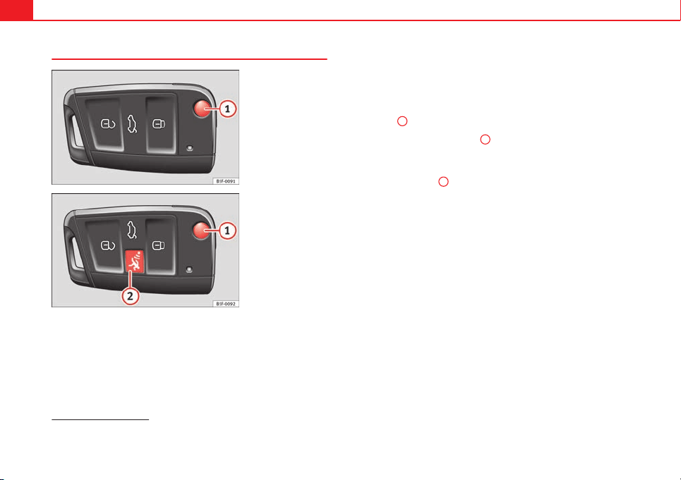
88 Opening and closing
Vehicle key
Fig. 43 Vehicle key
Fig. 44 Vehicle key with
alarm button
Vehicle key
With the vehicle key the vehicle may be locked or unlocked remotely
⇒
page 86.
The vehicle key includes an emitter and battery. The receiver is in the interi-
or of the vehicle. The range of the vehicle key with remote control and new
battery is several metres around the vehicle.
If it is not possible to open or close the vehicle using the remote control key,
this should be re-synchronised ⇒ page 90 or the battery changed
⇒ page 90.
Different keys belonging to the vehicle may be used.
Unfolding and folding the key shaft
Press button
1
⇒ Fig. 43 or ⇒ Fig. 44 to unlock and unfold the key shaft.
To fold the shaft away, press button
1
and fold the key shaft in until it
locks in place.
Alarm button
1)
Only press alarm button
2
in the event of an emergency! When the alarm
button is pressed, the vehicle horn is heard and the turn signals are switch-
ed on for a short time. When the alarm button is pressed again, the alarm is
switched off.
Replacing a key
To obtain a spare key and other vehicle keys, the vehicle chassis number is
required.
Each new key contains a microchip which must be coded with the data from
the vehicle electronic immobiliser. A vehicle key will not work if it does not
contain microchip or the microchip has not been encoded. This is also true
for keys which are specially cut for the vehicle.
The vehicle keys or new spare keys can be obtained from a SEAT Official
Service, a specialised workshop or an approved key service qualified to cre-
ate this kind of key.
New keys or spare keys must be synchronised before use ⇒ page 90.
1)
This system is only available in some markets
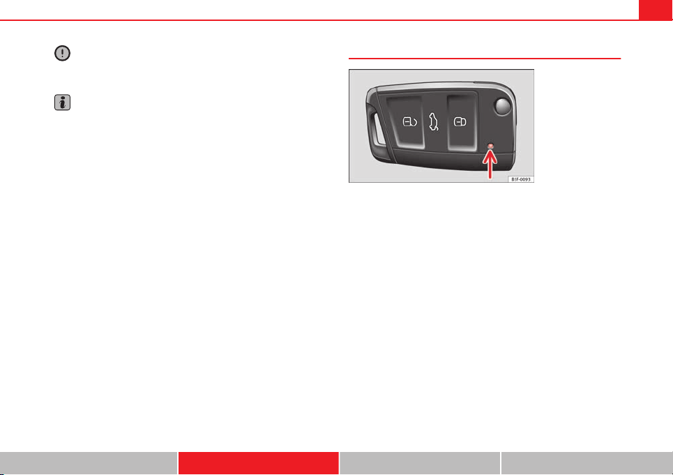
89Opening and closing
CAUTION
All of the vehicle keys contain electronic components. Protect the vehicle
keys from damage, impacts and humidity.
Note
● Only use the key button when you require the corresponding function.
Pushing the button unnecessarily could accidentally unlock the vehicle or
trigger the alarm. It is also possible even when you are outside the radius of
action.
● Key operation can be greatly influenced by overlapping radio signals
close the vehicle working in the same range of frequencies, for example, ra-
dio transmitters, mobile telephones.
● Obstacles between the remote control and the vehicle, bad weather con-
ditions and discharged batteries can considerably reduce the range of the
remote control.
● If buttons ⇒ Fig. 43 or ⇒ Fig. 44 on the vehicle key, or one of the central
locking buttons ⇒ page 93 are pressed repeatedly in short succession,
the central locking is briefly switched off to protect against overloading. The
vehicle is then unlocked. Lock the vehicle if necessary.
Control lamp on the vehicle key
Fig. 45 Control lamp on
the vehicle key
When a button on the vehicle key is pressed, the control lamp flashes
⇒ Fig. 45 (arrow) once briefly. If the button is pressed and held down, the
lamp flashes several times, for example: for the convenience opening func-
tion.
If the vehicle key control lamp does not light up when the button is pressed,
replace the battery ⇒ page 90.
Safety First Operating instructions Practical Tips Technical specifications
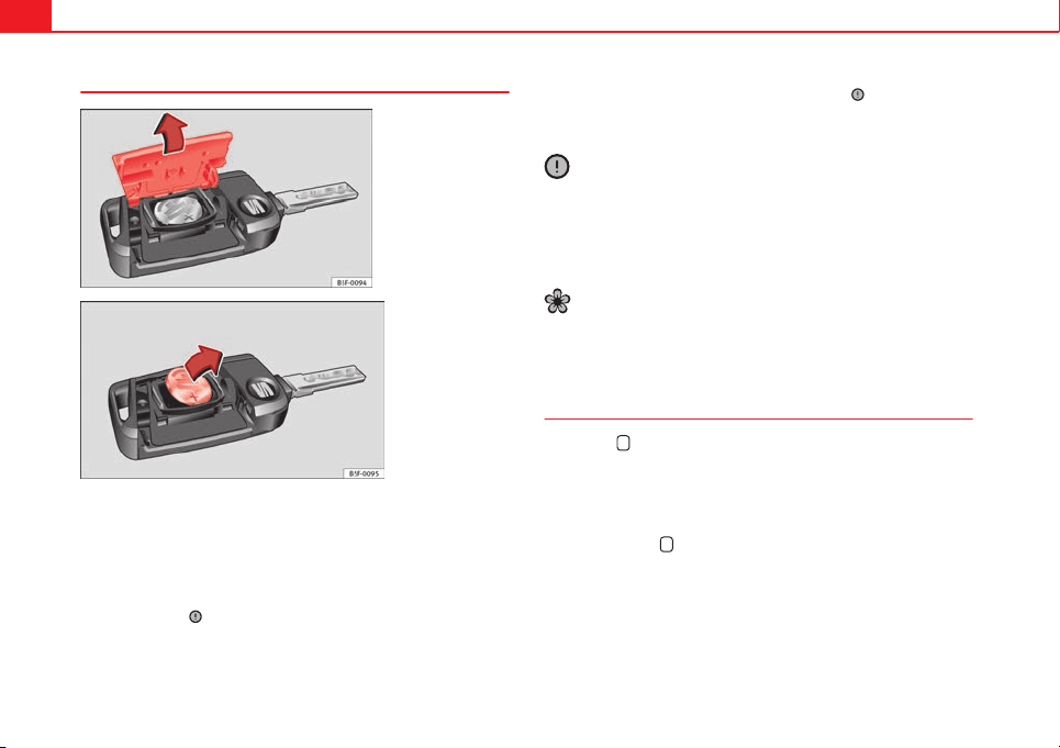
90 Opening and closing
Changing the battery
Fig. 46 Vehicle key:
opening the battery com-
partment
Fig. 47 Vehicle key:
removing the battery
SEAT recommends you ask a specialised workshop to replace the battery.
The battery is located to the rear of the vehicle key, under a cover.
Changing the battery
● Unfold the vehicle key shaft
⇒
page 88.
● Remove the cover from the back of the vehicle key
⇒
Fig. 46 in the direc-
tion of the arrow
⇒
.
● Extract the battery from the compartment using a suitable thin object
⇒
Fig. 47.
● Place the new battery in the compartment as shown ⇒ Fig. 47, pressing
in the opposite direction to that shown by the arrow ⇒
.
● Fit the cover as shown ⇒ Fig. 46, pressing it onto the vehicle key casing
in the opposite direction to that shown by the arrow until it clicks into place.
CAUTION
● If the battery is not changed correctly, the vehicle key may be damaged.
● Use of unsuitable batteries may damage the vehicle key. For this reason,
always replace the dead battery with another of the same voltage, size and
specifications.
● When fitting the battery, check that the polarity is correct.
For the sake of the environment
Please dispose of your used batteries correctly and with respect for the envi-
ronment.
Synchronising the vehicle key
If the button
is pressed frequently outside of the vehicle range, it is pos-
sible that the vehicle can no longer be locked or unlocked using the key. In
this case, the key must be resynchronised as described below:
● Unfold the vehicle key shaft
⇒
page 88.
● If necessary, remove the cover from the driver door lever
⇒
page 97.
● Press the button
on the vehicle key. For this, it must remain with the
vehicle.
● Open the vehicle within one minute using the key shift. The key has
been synchronised.
● If necessary, fit the cap.
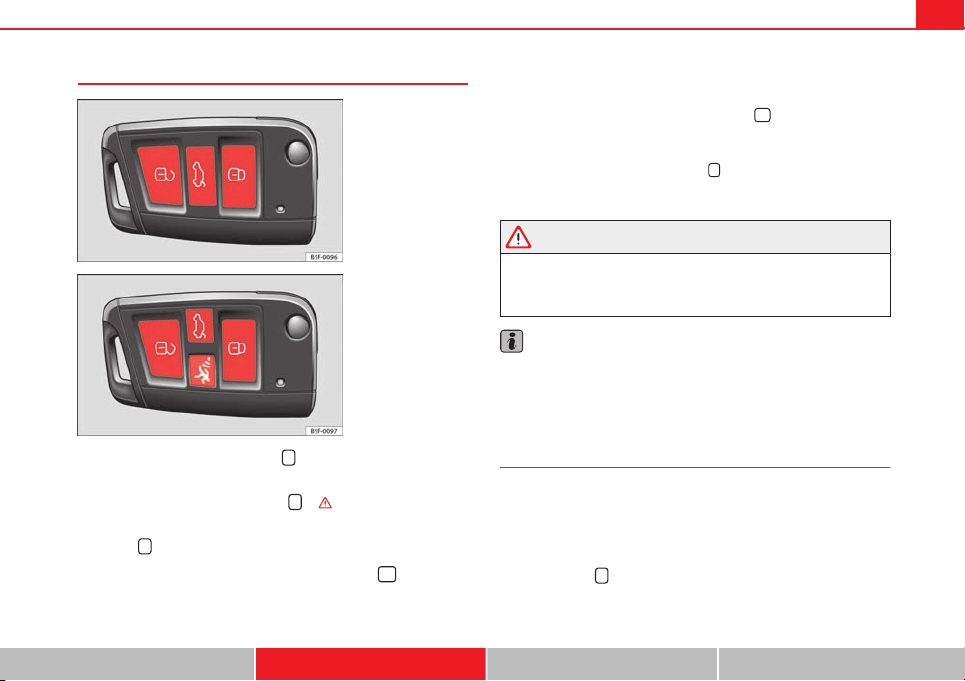
91Opening and closing
Remote unlocking/Locking
Fig. 48 Remote control
key: Buttons
Fig. 49 Remote control
key: Buttons
– To unlock the vehicle, press the
button ⇒ Fig. 48.
– To lock the vehicle, place the selector lever in position P (auto-
matic gearbox) and press button
⇒ .
– To lock the vehicle without the anti-theft security system*, press
button
again
for the next 2 seconds
.
– To unlock the rear lid, press and hold the button
for at least
one second.
The vehicle will be locked again automatically if you do not open one of the
doors or the rear lid within 30 seconds after unlocking the car. This function
prevents the vehicle from remaining unlocked if the unlocking button is
pressed by mistake. This is not valid if the button
is held down for at
least one second.
In vehicles with a security central locking feature (selective unlocking of
side doors) ⇒ page 91, when the button
is pressed once, only the driv-
er door and the fuel tank flap are unlocked. When the button is pressed a
second time, all the vehicle doors are unlocked.
WARNING
Do not leave anyone (especially children) in the vehicle if it is locked from
the outside and the anti-theft security system* is enabled, as the doors
and windows cannot then be opened from the inside. Locked doors could
delay assistance in an emergency, potentially putting lives at risk.
Note
● Do not use the remote control key until the vehicle is visible.
● Other functions of the remote control key ⇒ page 101, Convenience
opening/closing.
Selective unlocking system
The selective unlocking system allows you to only unlock the driver
door and the fuel tank flap. All other doors and the rear lid remain
locked.
Unlocking the driver door and tank flap
– Press button
on the remote control key once, or turn the key
once to open.
Safety First Operating instructions Practical Tips Technical specifications

92 Opening and closing
Unlocking all the doors, the rear lid and the tank flap
simultaneously.
– Within 5 seconds, press button
on the remote control key
twice, or turn the key to open twice within 5 seconds.
The anti-theft security system* and the anti-theft alarm* are immediately
disabled if you unlock only the driver door, without unlocking the other
doors.
In vehicles with Easy Connect*, you can programme the security central
locking system directly ⇒ page 92.
Programming the central locking system
You can use Easy Connect* to select which doors are unlocked with
the central locking system. Using the radio or the Easy Connect*
system, you can select whether the vehicle automatically closes
with the “Auto Lock” programme at speeds of more than 15 km/h
(10 mph).
Programming the unlocking of the doors (vehicles with Easy
Connect)
– Select: control button Systems or Vehicle systems > Vehicle set-
tings > Central locking > Unlocking doors.
Programming the Auto Lock (vehicles with radio)
– Select:
SETUP
button > control button Central locking > Locking
while driving.
Programming the Auto Lock (vehicles with Easy Connect)
– Select: control button Systems or Vehicle systems > Vehicle set-
tings > Locking while driving.
Unlocking the doors - You can programme the system to unlock all the doors
or only the driver door when you unlock the vehicle. In all the options, the
fuel tank flap is also unlocked.
With the setting, Driver, all the doors and the rear lid are unlocked if button
on the remote control key is pressed twice.
With this setting, you can continue to unlock all the vehicle doors. To do so,
press button
on the remote control key twice. Or, in vehicles with a con-
ventional key, turn the key to open in the door lock twice within 2 seconds.
If the button
is pressed, all the vehicle doors are locked. At the same
time, a confirmation signal is heard
1)
.
Auto Lock/Locking while driving - If you select on, all the vehicle doors are
locked at speeds above 15 km/h (10 mph).
1)
This function is not available on all export versions.
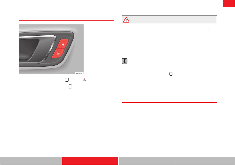
93Opening and closing
Central locking switch
Fig. 50 Driver door: cen-
tral locking switch
– To lock the vehicle, press the
button ⇒ .
– To unlock the vehicle, press the
button ⇒ Fig. 50.
Please note the following when using the central locking switch to lock your
vehicle:
● It is not possible to open the doors or the rear lid from the outside (for
safety reasons, e.g. when stopped at traffic lights).
● The LED in the central locking switch lights up when all the doors are
closed and locked.
● You can open the doors individually from the inside by pulling the inside
door handle.
● In the event of an accident in which the airbags inflate, doors locked
from the inside will be automatically unlocked to facilitate access and assis-
tance.
WARNING
● The central locking switch also operates when the ignition is switch-
ed off and automatically locks all the vehicle doors when the button
is
pressed.
● The central locking switch does not operate if the vehicle is locked
from the outside and the anti-theft security system is switched on.
● Locked doors could delay assistance in an emergency, potentially
putting lives at risk. Do not leave anyone (especially children) in the vehi-
cle.
Note
The doors and the rear lid are locked automatically when the vehicle rea-
ches a speed of about 15 km/h (10 mph) (Auto Lock) ⇒ page 86. You can
unlock the vehicle again using button
on the central locking switch.
Anti-theft alarm system
Description
The anti-theft alarm makes it more difficult to break into the vehicle or steal
it.
The anti-theft alarm is automatically turned on when the vehicle is locked
with the key.
When does the system trigger an alarm?
The anti-theft alarm siren will be triggered for about 30 seconds accompa-
nied by optical warning signals for about five minutes when the vehicle is
locked and the following unauthorised actions are taken:
Safety First Operating instructions Practical Tips Technical specifications

94 Opening and closing
● When the door is mechanically unlocked using the vehicle key without
turning the ignition within the following 15 seconds.
● A door is opened.
● The bonnet is opened.
● The rear lid is opened.
● When the ignition is switched on with a non-authorised key.
● When the vehicle battery is disconnected.
● Movement inside the vehicle (in vehicles with interior monitoring
⇒ page 95).
● When the vehicle is towed (in vehicles with anti-tow system
⇒ page 95).
● When the vehicle is raised (in vehicles with anti-tow system
⇒ page 95).
● When the vehicle is transported on a ferry or by rail (vehicles with an an-
ti-tow system or vehicle interior monitoring ⇒ page 95).
● When a trailer connected to the anti-theft alarm system is disconnected.
How to turn OFF the alarm
Unlock the vehicle with the unlocking button on the key or turn on the igni-
tion with a valid key.
Note
● The alarm will be triggered once more when anybody enters the same
zone of surveillance or any other zone. If, for example, after opening a door,
the rear lid is also opened.
● The anti-theft alarm
is not activated when the vehicle is locked from
the inside using the central locking button.
● If the driver door is unlocked mechanically with the key, only the driver
door is unlocked, the rest of the doors remain locked. Only when the igni-
tion has been turned on will the other doors be available - but not unlocked
- and the central lock button activated.
● If the vehicle battery is run down or flat then the anti-theft alarm will not
operate correctly.
Vehicle interior monitoring and anti-tow system*
Monitoring or control function incorporated in the anti-theft
alarm* which detects unauthorized vehicle entry by means
of ultrasound.
Activation
– It is automatically switched on when the anti-theft alarm is acti-
vated.
Deactivation
– Open the vehicle with the key, either mechanically
1)
or by press-
ing the
button on the remote control.
– Press the button
on the remote control twice. The volumetric
sensor and tilt sensors will be deactivated. The alarm system re-
mains activated.
The vehicle interior monitoring and the anti-tow system are automatically
switched on again next time the vehicle is locked.
1)
The time period from when the door is opened until the key is inserted in the contact
should not exceed 15 sec., otherwise the alarm will be triggered.
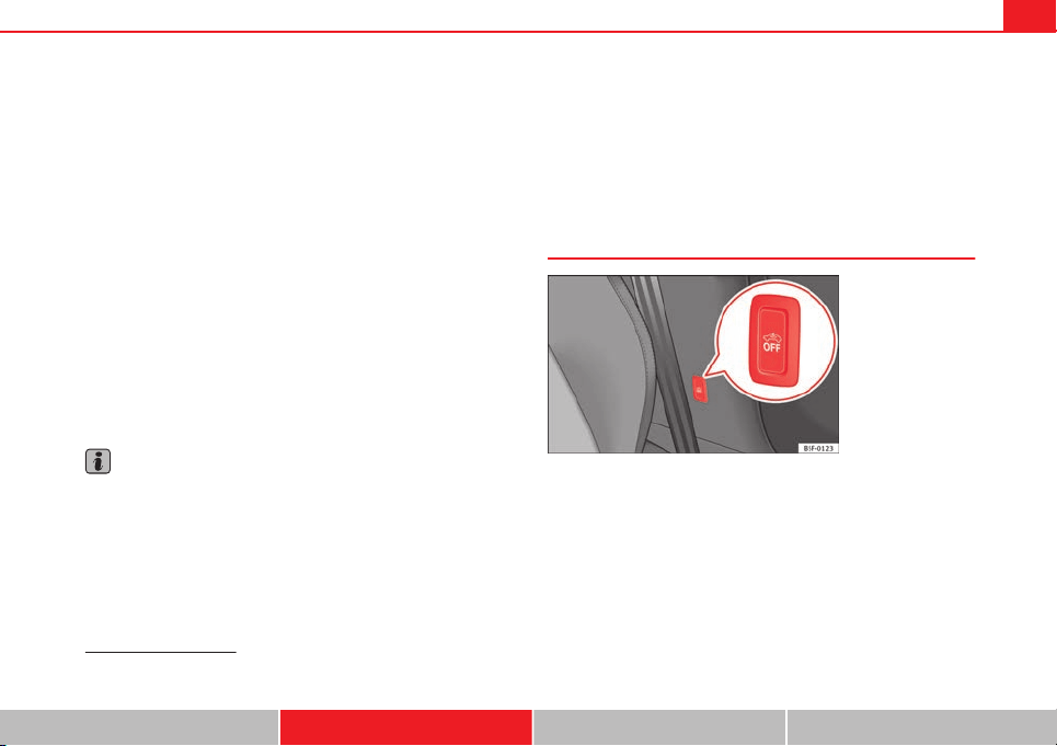
95Opening and closing
The vehicle interior monitoring and anti-tow sensor (tilt sensor) are auto-
matically switched on when the anti-theft alarm is switched on. In order to
activate it, all the doors and the rear lid must be closed.
If you wish to switch off the vehicle interior monitoring and the anti-tow sys-
tem, it must be done each time that the vehicle is locked; if not, they will be
automatically switched on.
The vehicle interior monitoring and the anti-tow system should be switched
off if animals are left inside the locked vehicle (otherwise, their movements
will trigger the alarm) or when, for example, the vehicle is transported or
has to be towed with only one axle on the ground.
False alarms
The interior monitoring only operates correctly if the vehicle is completely
closed. Please observe legal requirements when doing so.
The following cases may cause a false alarm:
● opened windows (partially or fully)
● panoramic/tilting sunroof open (partially or completely).
● movement of objects inside the vehicle, such as loose papers, items
hanging from the rear vision mirror (air fresheners), etc.
Note
● If the vehicle is relocked and the alarm is activated without the volumet-
ric sensor function, relocking will activate the alarm with all its functions,
except the volumetric sensor. This function is reactivated when the alarm is
switched on again, unless it is deliberately switched off.
● If the alarm has been triggered by the volumetric sensor, this will be in-
dicated by a flashing of the warning lamp on the driver door when the vehi-
cle is opened. The flash is different to the flash indicating the alarm is acti-
vated.
● The vibration of a mobile phone left inside the vehicle may cause the ve-
hicle interior monitoring alarm to trigger, as both sensors react to move-
ments and shakes inside the vehicle.
● If on activating the alarm, any door or the rear lid is open, only the alarm
will be activated. The vehicle interior monitoring and the anti-tow system
will only be activated once all the doors are closed (including the rear lid).
Deactivating the vehicle interior monitoring and tow-away
protection
1)
Fig. 51 Vehicle interior
monitoring/tow-away
protection button
When the vehicle is locked, the alarm will be triggered if move-
ments are detected in the interior (e.g. by animals) or if the vehi-
cle's inclination is changed (e.g. during transport). You can prevent
the alarm from being triggered accidentally by switching off the ve-
hicle interior monitoring and/or tow-away protection.
– To switch off the vehicle interior monitoring and tow-away pro-
tection, switch off the ignition and press button ⇒ Fig. 51. The
button will light up.
1)
Only available in certain markets.
Safety First Operating instructions Practical Tips Technical specifications
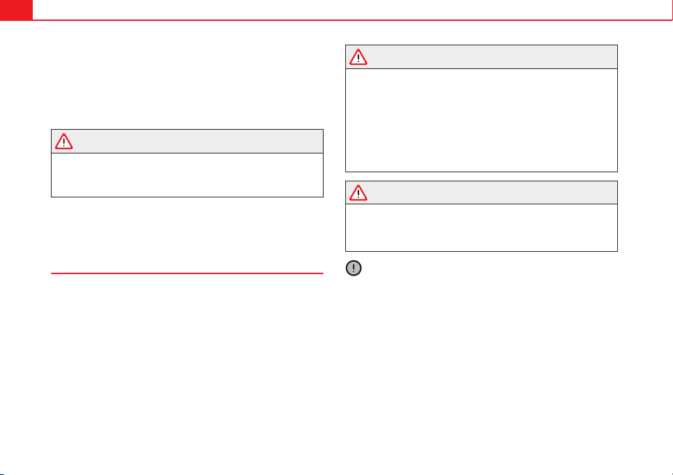
96 Opening and closing
– When the vehicle is locked now, the vehicle interior monitoring
and the tow-away protection are switched off until the next time
the door is opened.
If the anti-theft security system (Safelock)* ⇒ page 86 is switched off, the
vehicle interior monitoring and the tow-away protection are automatically
switched off.
WARNING
Do not leave anyone (especially children) in the vehicle if it is locked from
the outside and the anti-theft security system* is enabled, as the doors
and windows cannot then be opened from the inside. Locked doors could
delay assistance in an emergency, potentially putting lives at risk.
Emergency locking and unlocking
Introduction
The doors, rear lid and panoramic tilting sunroof can be locked manually
and partially opened, for example if the key or the central locking is dam-
aged.
Additional information and warnings:
● Vehicle key set ⇒ page 88
● Central locking and locking system ⇒ page 86
● Rear lid ⇒ page 98
WARNING
Opening and closing doors carelessly can cause serious injury.
● If the vehicle is locked from outside, the doors and windows cannot
be opened from the inside.
● Never leave children or disabled people alone in the car. They could
be trapped in the car in an emergency and will not be able to get them-
selves to safety.
● Depending on the time of the year, temperatures inside a locked and
closed vehicle can be extremely high or extremely low resulting in seri-
ous injuries and illness or even death, particularly for young children.
WARNING
Getting in the way of the doors and the rear lid is dangerous and can lead
to serious injury.
● Open and close the doors and the rear lid only when there is nobody
in the way.
CAUTION
When opening and closing in an emergency, carefully disassemble compo-
nents and then reassemble them carefully to avoid damage to the vehicle.
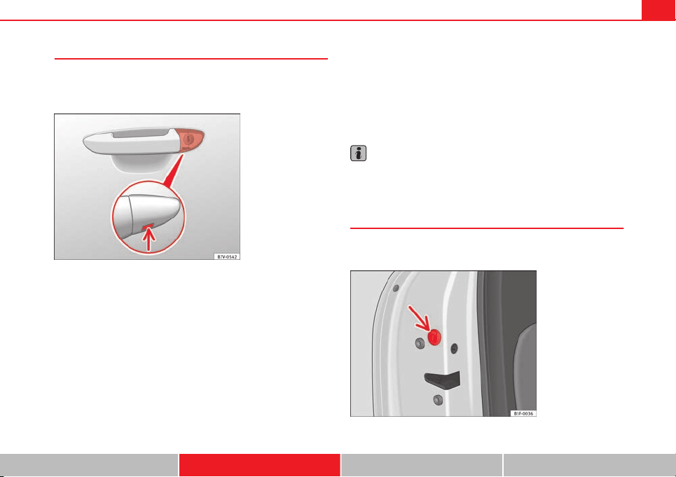
97Opening and closing
Unlocking or locking the driver door
If the central locking system should fail to operate, the driver
door can still be locked and unlocked by turning the key in
the lock.
Fig. 52 Driver door lever:
Hidden lock cylinder
As a general rule, when the driver door is locked all other doors are locked.
When the vehicle is unlocked manually, only the driver door opens. Please
observe the instructions relating to the anti-theft alarm system
⇒
page 86.
● Unfold the vehicle key shaft
⇒
page 88.
● Insert the key shaft into the opening in the cover on the driver door han-
dle from below
⇒
Fig. 52 (arrow) then remove the cover upwards.
● Insert the key shaft into the lock cylinder to unlock or lock the vehicle.
Unlocking notes:
● The anti-theft alarm will remain active when vehicles are unlocked. How-
ever, the alarm will not yet be triggered ⇒ page 86.
● After the driver door is opened, you have 15 seconds to switch on the
ignition. After 15 seconds, the alarm is triggered.
● Switch the ignition on. When the ignition is switched on, the electronic
immobiliser recognises a valid vehicle key and deactivates the anti-theft
alarm system.
Note
The anti-theft alarm is not activated when the vehicle is locked manually us-
ing the key shaft ⇒ page 86.
Manual locking of passenger door in an emergency
If the central locking system should fail to work at any time,
the passenger door will have to be locked separately.
Fig. 53 Locking the door
manually
Safety First Operating instructions Practical Tips Technical specifications
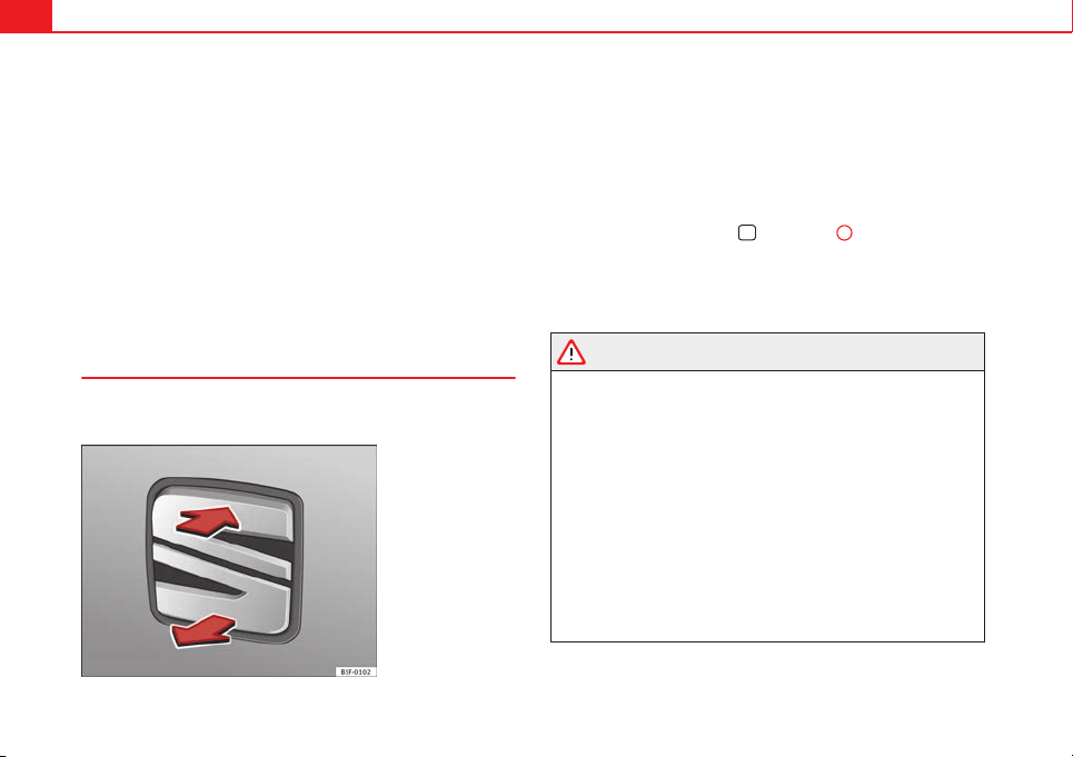
98 Opening and closing
A mechanical locking device (only visible when the door is open) is
provided on the front passenger door.
– Pull the cap out of the opening.
– Insert the key in the inside slot and turn it to the right as far as
it will go (if the door is on the right side) or to the left (if the
door is on the left side).
Once the door has been closed it can no longer be opened from the outside.
Pull the interior door handle once to unlock and open the door.
Rear lid (luggage compartment)
Rear lid
The rear lid opening system operates electrically. It is activa-
ted by using the handle on the rear lid.
Fig. 54 Rear lid: opening
from the outside
Opening the rear lid
– Pull on the release lever and lift the rear lid ⇒ Fig. 54. The rear
lid will automatically open.
Closing the rear lid
– Hold the rear lid by one of the two handles on the interior lining
and close it, pushing slightly.
To lock/unlock, press the button
or the button
1
on the remote control
key.
A warning appears on the instrument panel display if the rear lid is open or
not properly closed.* An audible warning is also given if the rear lid is
opened while the vehicle is moving faster than 6 km/h (4 mph).*
WARNING
● Always close the rear lid properly. Risk of accident or injury.
● The rear lid must not be opened when the reverse or rear fog lights
are lit. This may damage the tail lights
● Do not close the rear lid by pushing it down with your hand on the
rear window. The glass could smash. Risk of injury!
● Ensure the rear lid is locked after closing it. If not, it may open unex-
pectedly while driving.
● Never allow children to play in or around the vehicle. A locked vehicle
can be subjected to extremely high and low temperatures, depending on
the time of year, thus causing serious injuries/illness. It could even have
fatal consequences. Close and lock both the rear lid and all the other
doors when you are not using the vehicle.
● Closing the rear lid without observing and ensuring it is clear could
cause serious injury to you and to third parties. Make sure that no one is
in the path of the rear lid.
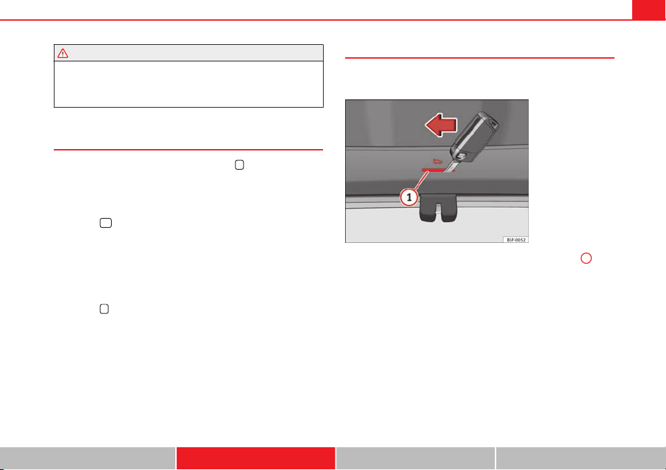
99Opening and closing
WARNING (Continued)
● Never drive with the rear lid open or half-closed, exhaust gases may
penetrate into the interior of the vehicle. Danger of poisoning!
● If you only open the rear lid, do not leave the key inside. The vehicle
will not be opened if the key is left inside.
Automatic rear lid locking
Where the vehicle has been locked by pressing the
button on the remote
control with the rear lid open, the rear lid will lock automatically when
closed.
The automatic rear lid locking time extension function can be activated.
Where this function is activated and once the rear lid has been unlocked by
pressing the
button on the remote control key ⇒ page 91, the rear lid
can be re-opened for a certain length of time.
Where required, the automatic rear lid locking time extension function can
be activated or deactivated at a SEAT Authorised Service, which will provide
all of the necessary information.
Before the vehicle locks automatically, there is a risk of intruders getting in-
to the vehicle. Therefore, we recommend you always lock the vehicle by
pressing the
button on the remote control or by using the central locking
button.
Manual release of the rear lid in an emergency
The rear lid can be unlocked manually from inside in the
event of an emergency.
Fig. 55 Luggage com-
partment: access to man-
ual release
– Insert the key in the opening in the lining of the rear lid
1
and
move the key in the direction of the arrow until the lock is re-
leased.
Safety First Operating instructions Practical Tips Technical specifications
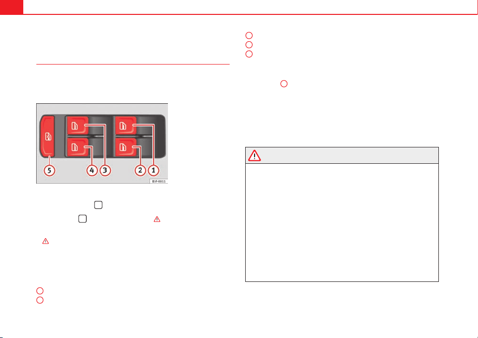
100 Opening and closing
Electric windows
Electronic control of windows*
The front and rear electric windows can be operated by us-
ing the controls on the driver door. The other doors each
have a switch for their own window.
Fig. 56 Detail of the driv-
er door: controls for the
front and rear windows
Opening and closing the windows
– Press the button
to open the window.
– Pull button
to close the window ⇒ .
Always close the windows fully if you park the vehicle or leave it unattended
⇒
.
You can use the electric windows for approx. 10 minutes after switching off
the ignition if neither the driver door nor the front passenger door has been
opened and the key has not been removed from the ignition.
Buttons on the driver door
Button for window in front left door
Button for window in front right door
1
2
Button for window in rear left door
Button for window in rear right door
Safety switch for deactivating the electric window buttons in the rear
doors
Safety switch *
Safety switch
5
on the driver door can be used to disable the electric win-
dow buttons in the rear doors.
Safety switch not pressed: buttons on rear doors are activated.
Safety switch pressed: buttons on rear doors are deactivated.
The safety control symbol lights up in yellow if the buttons on the rear
door are switched off.
WARNING
● Incorrect use of the electric windows can result in injury.
● Never close the rear lid without observing and ensuring it is clear, to
do otherwise could cause serious injury to you and third parties. Make
sure that no one is in the path of a window.
● Always take the vehicle key with you when you leave the vehicle.
● Never leave children or disabled persons in the vehicle, particularly if
they have access to the keys. The misuse of the keys, for example, by
children, may result in serious injury and accident.
● The engine may accidentally be started and be out of control.
● If the ignition is switched on, the electric equipment could be activa-
ted with risk of injury, for example, in the electric windows.
● The doors can be locked using the remote control key. This could be-
come an obstacle for assistance in an emergency situation.
● Always take the key with you when you leave the vehicle.
3
4
5
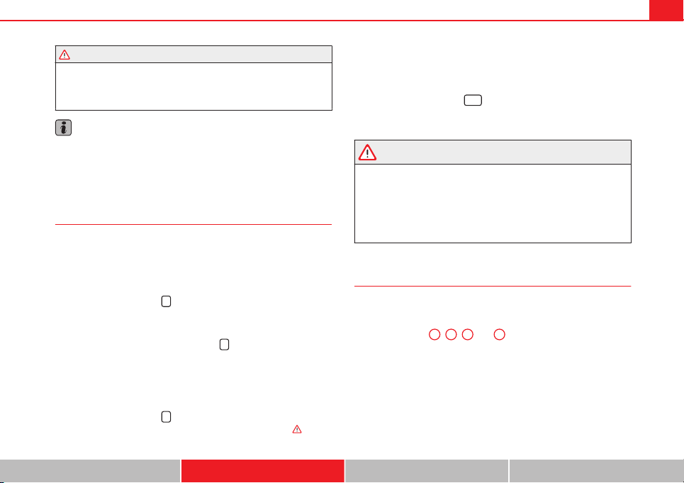
101Opening and closing
WARNING (Continued)
● The electric windows will work until the ignition has been switched
off and one of the front doors has been opened.
● If necessary, use the safety switch to disable the rear electric win-
dows. Make sure that they have been disabled.
Note
If the window is not able to close because it is stiff or because of an ob-
struction, the window will automatically open again ⇒ page 102. If this
happens, check why the window could not be closed before attempting to
close it again.
Convenience opening/closing
Use the convenience opening/closing function to easily open/
close all the windows and the sliding/tilting sunroof* from the out-
side.
Convenience open function
– Press and hold button
on the remote control key until all the
windows and the sliding/tilting sunroof* have reached the de-
sired position, or
– First unlock the vehicle using button
on the remote control
key and then keep the key in the driver door lock until all the
windows and the sliding/tilting sunroof* have reached the re-
quired position.
Convenience close function
– Press and hold button
on the remote control key until all the
windows and the sliding/tilting sunroof* are closed ⇒
, or
– Keep the key in the driver door in the "lock" position until all the
windows and the sliding/tilting sunroof* are closed.
Programming convenience opening in the Easy Connect*
– Select: function button
CAR
> control button Vehicle systems* >
Vehicle settings > Central locking > Open the window by holding
button down or > Front window on/off or Sunroof on/off*
WARNING
● Take care when closing the sliding/tilting sunroof* and windows.
There is a risk of suffering injury.
● For safety reasons, you should only use the remote control open and
close functions within about 2 metres of the vehicle. To avoid injuries, al-
ways keep an eye on the windows and the sliding/tilting sunroof* when
pressing the button to close them. The windows stop moving as soon as
the button is released.
One-touch opening and closing*
One-touch opening and closing means you do not have to
hold down the button.
Buttons ⇒ Fig. 56
1
,
2
,
3
and
4
have two positions for open-
ing windows and two for closing them. This makes it easier to open
and close windows to the desired position.
One-touch closing
– Pull up the window button briefly up to the second position. The
window closes fully.
Safety First Operating instructions Practical Tips Technical specifications
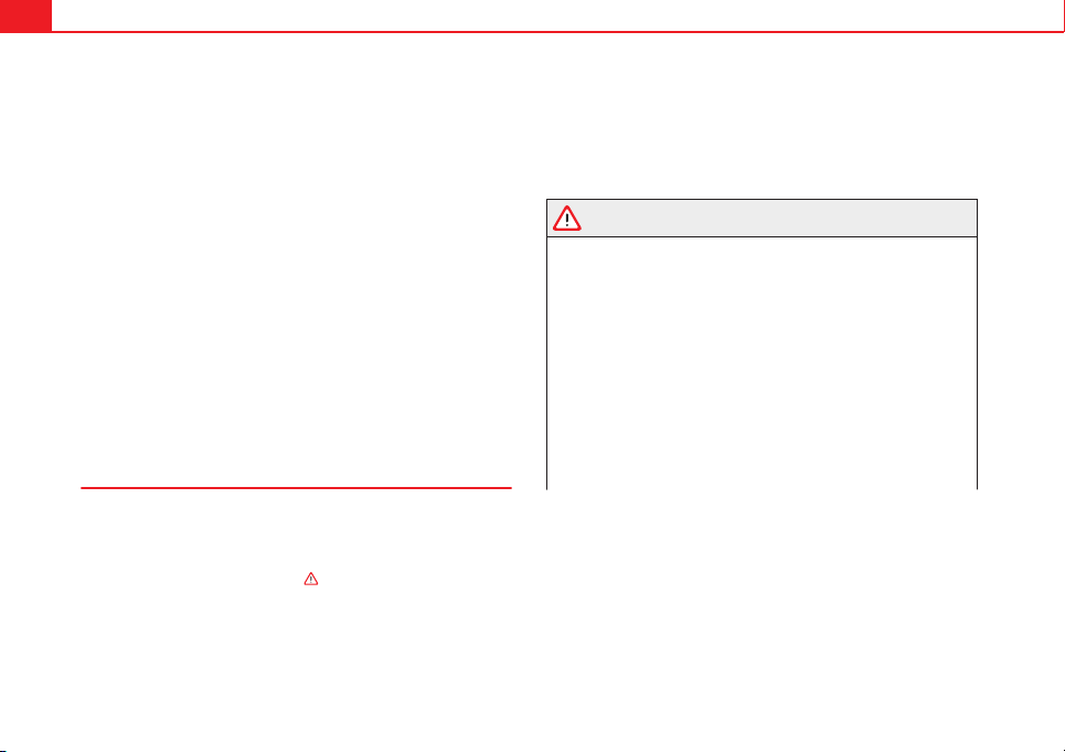
102 Opening and closing
One-touch opening
– Push down the window button briefly up to the second position.
The window opens fully.
Restoring one-touch opening and closing
– The automatic open and close function will not work if the bat-
tery has been temporarily disconnected. The function can be re-
stored as follows:
– Close the window as far as it will go by lifting and holding the
electric window switch.
– Release the switch and then lift it again for one second. This
will re-enable the automatic function.
If you push (or pull) a button to the first stage, the window will open (or
close) until you release the button. If you push or lift the button briefly to
the second stage, the window will open (one-touch opening) or close (one-
touch closing) automatically. If you operate the button while the window is
opening or closing, it stops at this position.
Roll-back function
The roll-back function reduces the risk of injury when the
electric windows close.
● If a window is obstructed when closing automatically, the window stops
at this point and lowers immediately ⇒
.
● Next, check why the window does not close before attempting it again.
● If you try within the following 10 seconds and the window closes again
with difficulty or there is an obstruction, the automatic closing will stop
working for 10 seconds.
● If the window is still obstructed, the window will stop at this point.
● If there is no obvious reason why the window cannot be closed, try to
close it again by pulling the tab within ten seconds. The window closes with
maximum force. The roll-back function is now deactivated.
If more than 10 seconds pass, the window will open fully when you operate
one of the buttons. One-touch closing is reactivated.
WARNING
● Incorrect use of the electric windows can result in injury.
● Always take the ignition key with you when leaving the vehicle, even
if you only intend to be gone for a short time. Please ensure that children
are never left alone inside the vehicle.
● The electric windows will work until the ignition has been switched
off and one of the front doors has been opened.
● Closing the windows without observing and ensuring it is clear could
cause serious injury to you and third parties. Make sure that no one is in
the path of a window.
● Never allow people to remain in the vehicle when you close the vehi-
cle from the outside. The windows cannot be opened even in an emergen-
cy.
● The roll-back function does not prevent fingers or other parts of the
body getting pinched against the window frame. Risk of accident.
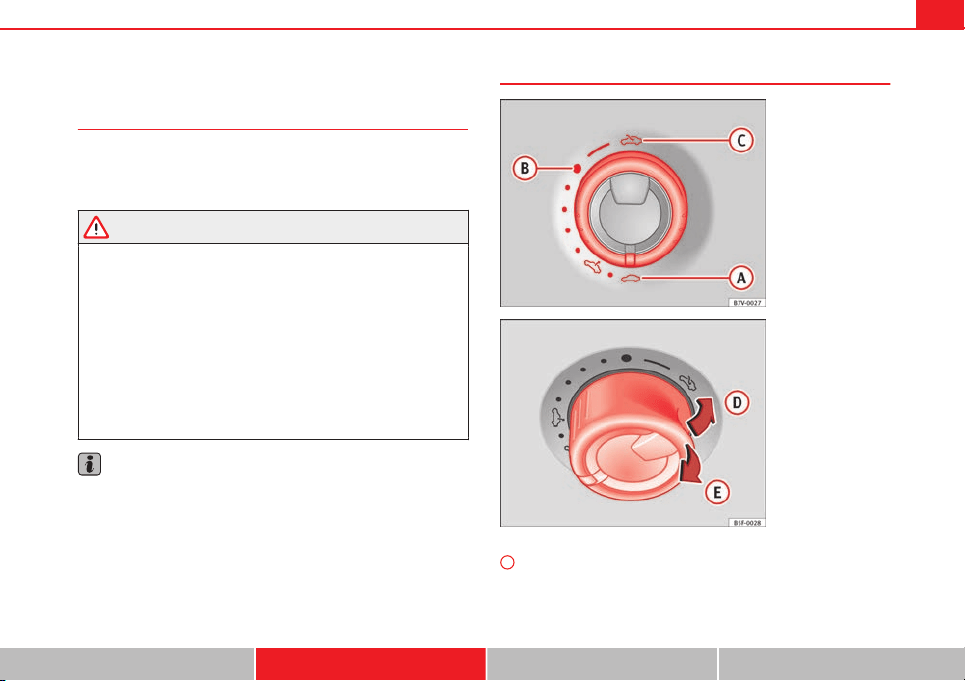
103Opening and closing
Panoramic sliding sunroof*
Introduction
Additional information and warnings:
● SEAT information system ⇒ page 73
● Central locking and locking system ⇒ page 86
WARNING
Careless or uncontrolled use of the panoramic sliding sunroof can cause
serious injuries.
● Only open or close the panoramic sliding sunroof when nobody is in
the way of its travel.
● Always take all the keys with you whenever you leave the vehicle.
● Never leave children or disabled persons in the vehicle, particularly if
they have access to the keys. Uncontrolled use of the key could lock the
vehicle, start the engine, turn on the ignition and operate the panoramic
sliding sunroof.
● The panoramic sliding sunroof can be operated for up to about ten mi-
nutes after the ignition has been switched off, provided the driver door
and the front passenger door are not opened.
Note
In case of a fault in the operation of the panoramic sliding sunroof, the anti-
trap function will not operate correctly. Visit a specialised workshop.
Opening or closing the panoramic sliding sunroof
Fig. 57 On the interior
roof lining: use the rotary
button for opening and
closing
Fig. 58 On the interior
roof lining: Press the but-
ton and pull on it to lift
and close the sliding
sunroof
To open the panoramic sliding sunroof, the switch must be in the position
A
.
Safety First Operating instructions Practical Tips Technical specifications
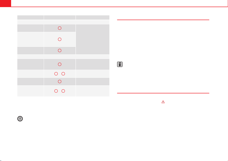
104 Opening and closing
Function Switch setting Necessary operations
⇒ Fig. 57
To open the sliding
sunroof completely:
C
Rotate the switch to the re-
quired position.
To choose the con-
venience position
for the sliding sun-
roof:
B
To close the sliding
sunroof completely:
A
⇒ Fig. 58
To completely de-
ploy the tilting sun-
roof:
D
Briefly push the switch up
(arrow).
To stop automatic
operation:
D
or
E
Briefly push back the but-
ton again or pull it.
To completely close
the tilting sunroof:
E
Briefly push the switch up
(arrow).
To set the inter-
mediate position:
D
or
E
Push the button up or
hold it back until the roof
is in the required position.
The panoramic sliding sunroof will only work with the ignition on. The pan-
oramic sliding sunroof can be operated for up to about ten minutes after the
ignition has been switched off, provided the driver door and the front pas-
senger door are not opened.
CAUTION
Check that when the rear lid is open, it does not touch loads carried on the
roof. When a roof carrier is fitted, DO NOT open the panoramic roof*.
Panoramic sliding sunroof: operation
Convenience open/close function
The panoramic sliding sunroof can be opened or closed from outside the
vehicle using the vehicle key:
● Keep the vehicle unlocking or locking button pressed. The panoramic
sliding sunroof is adjusted or closes.
● Release the unlock or lock button to stop the function.
During convenience closing, first the windows and then the panoramic slid-
ing sunroof will be closed.
Note
The panoramic sliding sunroof rotary button remains in the last position se-
lected if the roof is closed using convenience closing from outside the vehi-
cle and will have to be re-positioned the next time you drive.
Roll-back function on panoramic sliding sunroof
The roll-back function can reduce the risk of injury when opening and clos-
ing the panoramic sliding sunroof ⇒
. When the panoramic sliding sun-
roof encounters an obstacle while closing, it rolls back and opens again.
● Check why the panoramic sliding sunroof does not close.
● Try to close the panoramic sliding sunroof again.
● If the panoramic sliding sunroof is still obstructed, it will stop at the cor-
responding position. Next, close the panoramic sliding sunroof without the
roll-back function.
105Opening and closing
Closing without the roll-back function
● The ⇒ Fig. 57
1
switch should be in the “closed” position
A
.
● Within five seconds of triggering the roll-back function, pull the control
all the way back ⇒ Fig. 58 (arrow
E
) until the panoramic sliding sunroof
closes fully.
● The panoramic sliding sunroof closes without the roll-back function.
● If the panoramic sliding sunroof still cannot be closed, visit a special-
ised workshop.
WARNING
Closing the panoramic sliding sunroof without the roll-back function may
result in serious injury.
● Always close the panoramic sliding sunroof carefully.
● Make sure that nobody is in the way of the panoramic sliding sunroof,
especially when it is closed without the roll-back function.
● The anti-trap function does not prevent fingers or other parts of the
body getting pinched against the window frame and causing injury.
Note
The anti-trap function is activated if the windows and the panoramic sliding
sunroof are closed from the outside of the vehicle using the ignition key for
convenience closing ⇒ page 101.
Safety First Operating instructions Practical Tips Technical specifications
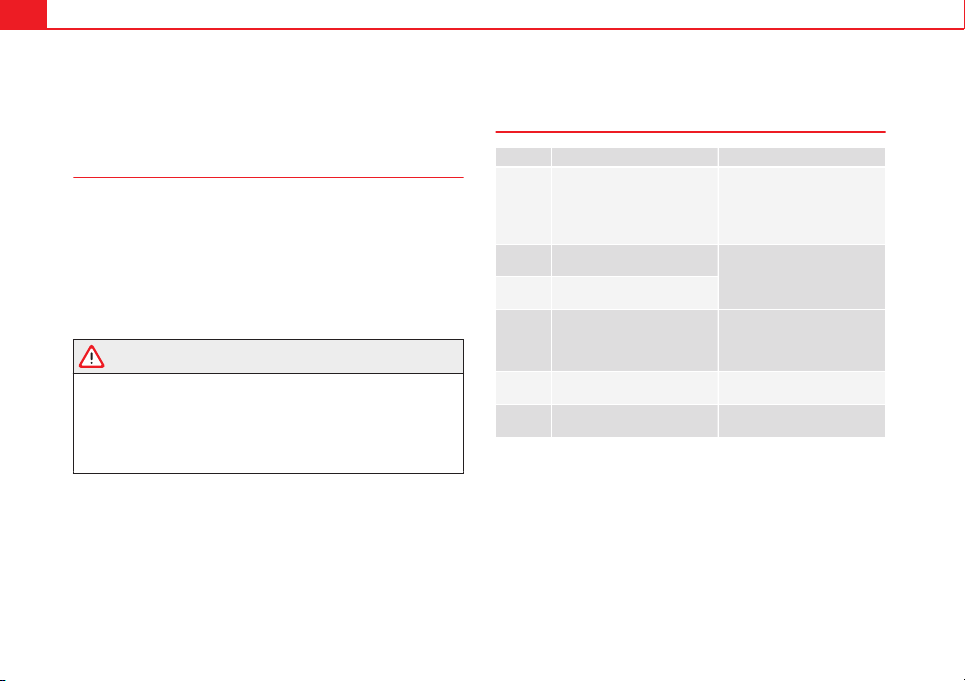
106 Lights and visibility
Lights and visibility
Lights
Introduction
The legal requirements regarding the use of vehicle lights in each country
must be observed.
The driver is personally responsible for the correct use and adjustment of
the lights in all situations.
Additional information and warnings:
● Information system ⇒ page 73
● Changing bulbs ⇒ page 252
WARNING
If the headlights are regulated too high and the main beam is not used
correctly, there is a risk of dazzling or distracting other road users. This
could result in a serious accident.
● Always make sure that the headlights are correctly adjusted.
● Never use the main beam or headlight flasher when it can dazzle oth-
er drivers.
Control lamps
lights up Possible cause Solution
Driving light totally or partially
faulty.
Replace the corresponding
bulb ⇒ page 252.
If all the bulbs are OK, the vehi-
cle should be taken to a speci-
alised workshop if necessary.
Rear fog light switched on.
⇒ page 108.
Fog lights switched on
Left or right turn signal.
The control lamp flashes twice
as fast when a vehicle or trailer
turn signal is faulty.
If necessary, check the vehicle
and trailer lighting.
Main beam on or flasher on. ⇒ page 107.
Light Assist on. ⇒ page 109.
Several warning and control lamps should light up for a few seconds when
the ignition is switched on, signalling that the function is being verified.
They will switch off after a few seconds.
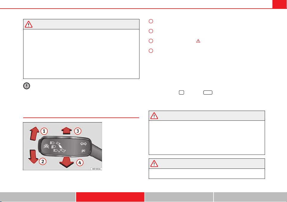
107Lights and visibility
WARNING
If the warning lamps and messages are ignored, the vehicle may stall in
traffic, or may cause accidents and severe injuries.
● Never ignore the warning lamps or text messages.
● Stop the vehicle safely as soon as possible.
● Park the vehicle at a suitable distance away from the traffic ensuring
that the exhaust system is not in contact with inflammable material, for
example, dry grass, fuel, oil, etc.
● A faulty vehicle represents a risk of accident for the driver and for oth-
er road users. If necessary, switch on the hazard warning lamps and put
out the warning triangle to advise other drivers.
CAUTION
Failure to heed the control lamps and text messages when they appear may
result in faults in the vehicle.
Turn signal and main beam lever*
Fig. 59 Turn signal and
main beam lever
Move the lever to the required position:
Right turn signal. Right-hand parking light (ignition switched off)
⇒ page 109.
Left turn signal. Left-hand parking light (ignition switched off)
⇒ page 109.
Main beam switched on ⇒
. The control lamp will light up on the
instrument panel.
Flashing the headlights. The flashed beam comes on if the lever is
pressed. The control lamp will light up.
Push the lever all the way down to turn off the corresponding function.
Convenience turn signals
For the convenience turn signals, move the lever as far as possible upwards
or downwards and release the lever. The turn signal will flash three times.
The convenience turn signals are activated and deactivated in the Easy Con-
nect system via the
key and the
Setup
function button ⇒ page 79.
In vehicles that do not have the corresponding menu, this function can be
deactivated in a specialised workshop.
WARNING
Improper or lack of use of the turn signals, or forgetting to deactivate
them can confuse other road users. This could result in a serious acci-
dent.
● Always give warning when you are going to change lane, overtake or
when turning, activating the turn signal in good time.
● As soon as you have finished changing lane, overtaking or turning,
switch the turn signal off.
WARNING
Incorrect use of the headlights may cause accidents and serious injury,
as the main beam may distract or dazzle other drivers.
1
2
3
4
Safety First Operating instructions Practical Tips Technical specifications
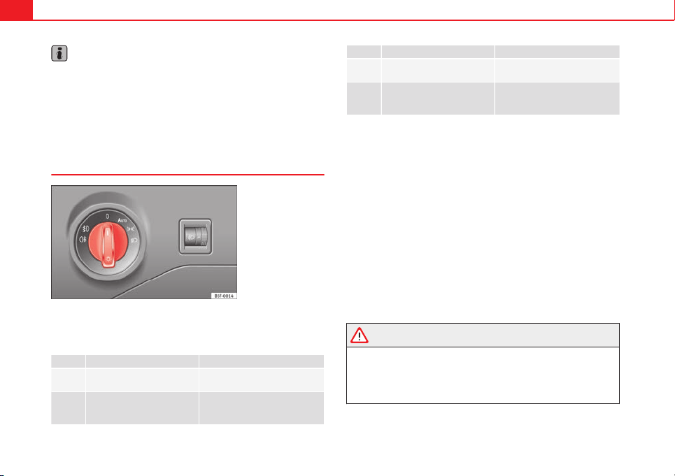
108 Lights and visibility
Note
● The turn signal only works when the ignition is switched on. The hazard
warning lights also work when the ignition is switched off.
● If a trailer turn signal malfunctions, the control lamp will stop flashing
(trailer turn signals) and the vehicle turn signal will flash at double speed.
● The main beam headlights can only be switched on if the dipped beam
headlights are already on.
Turning lights on and off
Fig. 60 Dash panel:
Light switch
The legal requirements regarding the use of vehicle lights in each country
must be observed.
Turn the light switch to the required position
⇒
Fig. 60:
Symbol if the ignition is switched off when the ignition is on
Fog lights, dipped beam and
side lights off.
Light off, or daytime driving light
on.
The “Coming home” and
“Leaving home” guide lights
may be switched on.
Automatic control of dipped
beam and daytime driving light.
Symbol if the ignition is switched off when the ignition is on
Side light on. Side light on.
Dipped beam off; if necessa-
ry, the side light comes on for
a time.
Dipped beam switched on.
Fog lights
The control lamps or also show, on the light switch or instrument pan-
el, when the fog lights are on.
● Switching on the fog lights : pull the light switch to the first stop, from
positions , or .
● Switching on the rear fog light : pull the light switch completely from
position , or .
● To switch off the fog lights, press the light switch or turn it to position .
Audible warnings to advise the driver that the lights have not been
switched off
If the key is not in the ignition and the driver door is open, an audible warn-
ing signal is heard in the following cases: This is a reminder to turn off the
lights.
● When the parking light is on ⇒ page 107.
● When the light switch is in position or .
WARNING
The side lights or daytime driving lights are not bright enough to illumi-
nate the road ahead and to ensure that other road users are able to see
you.
● Always use your dipped beam head lights if it is raining or if visibility
is poor.
109Lights and visibility
Lights and visibility: functions
Parking light
When the parking light is switched on, (right or left turn signal), the front
side light and the rear light on the corresponding side of the vehicle stay lit.
The parking lights can only be activated with the ignition switched off and
the turn signal and main beam lever in the central position, before being
triggered.
Parking light on both sides
With the ignition switched off and the light switch in position , when lock-
ing the vehicle from the outside, the parking lights on both sides of the ve-
hicle light up. In doing so, only the side lights of both headlights light up,
and additionally the tail lights will do so partially.
Daytime driving light*
The daytime driving lights consist of individual lights, integrated in the front
headlights. With the daylight driving lights on, only these lights switch on
⇒
.
The daytime driving lights switch on every time the ignition is switched on,
if the switch is in positions or , according to the level of exterior light-
ing.
When the light switch is in position , a light sensor automatically
switches dipped beam on and off (including the control and instrument
lighting) or the daytime driving lights depending on the level of exterior
lighting.
Automatic dipped beam control
The automatic dipped beam control is merely intended as an aid and is not
able to recognise all driving situations.
When the light switch is in position , the vehicle lights and the instru-
ment panel and switch lighting switch on and off automatically in the fol-
lowing situations ⇒
:
Automatic switching on: Automatic switching off:
The photo sensor detects darkness,
for example, when driving through a
tunnel.
When adequate lighting is detected.
The rain sensor detects rain and ac-
tivates the windscreen wipers.
When the windscreen wipers have
been inactive for a few minutes.
Cornering lights*
1)
When turning slowly or on very tight bends, the cornering lights are activa-
ted automatically. The cornering lights may be integrated in the fog lights
and are switched on only at speeds of less than 40 km/h (25 mph).
When reverse gear is engaged, the cornering lights on both sides of the ve-
hicle switch on, in order to better illuminate the area for parking.
Motorway lights*
The motorway lights are available on vehicles equipped both with full-LED
lights and headlights that switch on automatically.
● They are activated when the light switch is in position .
● They are deactivated when the light switch is not in position .
When going above 110 km/h (75 mph) for more than 30 seconds, the dip-
ped beam raises slightly to increase the distance of visibility of the driver.
When reducing the speed of the car below 100 km/h (60 mph), the dipped
beam returns to its normal position.
1)
This function is not available on vehicles equipped with full-LED headlights.
Safety First Operating instructions Practical Tips Technical specifications
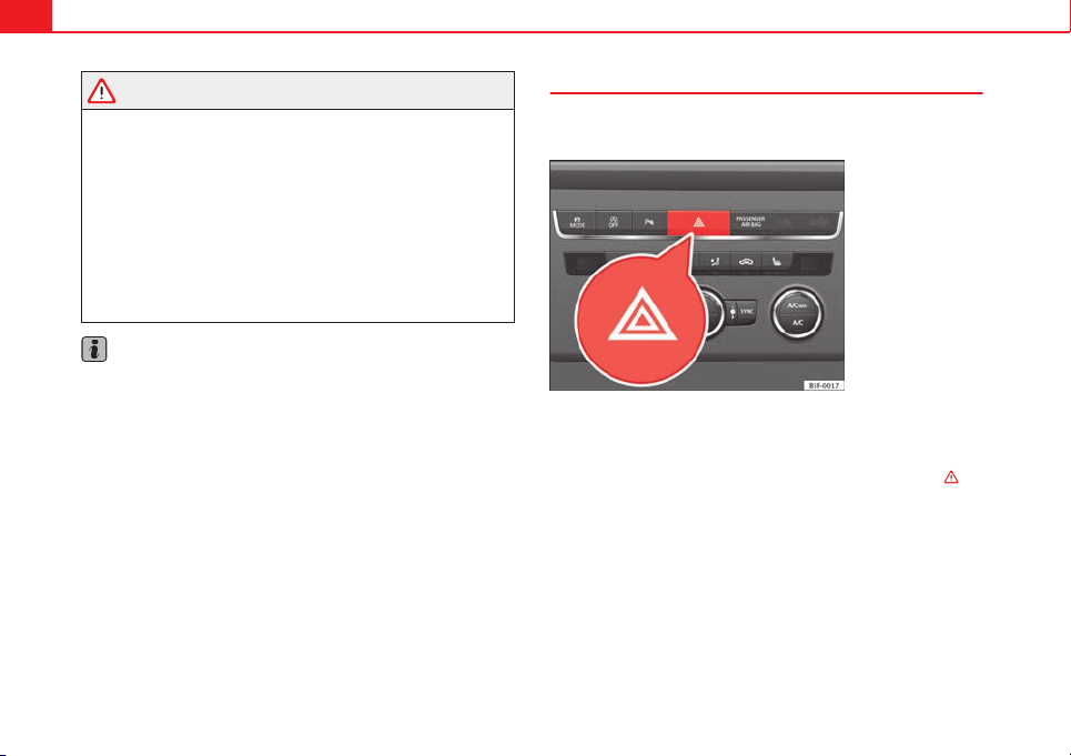
110 Lights and visibility
WARNING
If the road is not well lit and other road users cannot see the vehicle well
enough or at all, accidents may occur.
● The automatic dipped beam control () only switches on the dip-
ped beam when there are no changes in brightness, and not, for example
when it is foggy.
● Never drive with daytime lights if the road is not well lit due to weath-
er or lighting conditions. Daytime lights do not provide enough light to
illuminate the road properly or be seen by other road users.
● The rear lights do not come on with the daytime driving light. A vehi-
cle which does not have the rear lights on may not be visible to other
drivers in the darkness, in the case of heavy rain or in conditions of poor
visibility.
Note
In cold or damp weather conditions, the headlights, tail lights and turn sig-
nals may mist up inside temporarily. This is normal and in no way effects
the useful life of the vehicle lighting system.
Hazard warning lights
The hazard warning lights are used to draw the attention of
other road users to your vehicle in emergencies.
Fig. 61 Dash panel:
switch for hazard warn-
ing lights
If your vehicle breaks down:
1. Park your vehicle at a safe distance from moving traffic.
2. Press the button to switch on the hazard warning lights ⇒
.
3. Switch the ignition off.
4. Apply the handbrake.
5. On a manual gearbox engage 1st gear. On an automatic gear-
box, move the selector lever to P.
6. Use the warning triangle to draw the attention of other road
users to your vehicle.
111Lights and visibility
7. Always take the vehicle key with you when you leave the vehi-
cle.
Switch on the hazard warning lights to warn other road users, for example:
● reaching the tail end of a traffic jam,
● there is an emergency
● your vehicle breaks down due to a technical fault,
● you are towing another vehicle or your vehicle is being towed.
All turn signals flash simultaneously when the hazard warning lights are
switched on. The two turn signal turn signal lamps and the turn signal
lamp in the switch will flash at the same time. The hazard warning lights
also work when the ignition is switched off.
Emergency braking warning
If the vehicle is braked suddenly and continuously at a speed of more than
80 km/h (50 mph), the brake light flashes several times per second to warn
vehicles driving behind. If you continue braking, the hazard warning lights
will come on automatically when the vehicle comes to a standstill. They
switch off automatically when the vehicle starts to move again.
WARNING
● The risk of an accident increases if your vehicle breaks down. Always
use the hazard warning lights and a warning triangle to draw the atten-
tion of other road users to your stationary vehicle.
● Never park where the catalytic converter could come into contact with
inflammable materials under the vehicle, for example dry grass or spilt
petrol. This could start a fire!
Note
● The battery will run down if the hazard warning lights are left on for a
long time, even if the ignition is switched off.
● The use of the hazard warning lights described here is subject to the rel-
evant statutory requirements.
Main beam assist*
Main beam assist (Light Assist)
The main beam assist operates, within the limits of the system and depend-
ing on the environmental and traffic conditions, as of a speed of 60 km/h
(40 mph) when it switches on automatically, and is then deactivated again
below 30 km/h (20 mph) ⇒
. This is managed via a camera situated on
the base of the interior rear vision mirror.
The main beam assist generally detects illuminated areas and deactivates
the main beam when passing through a town, for example.
Safety First Operating instructions Practical Tips Technical specifications
112 Lights and visibility
Switching the main beam assist on and off
Function Action
Activate:
– Switch the ignition on and turn the light switch to position
.
– From the base position, move the main beam and turn signal
lever forwards ⇒ page 107. When the warning lamp is dis-
played on the instrument panel display, the main beam assist is
switched on.
Deacti-
vate:
– Switch off the ignition.
– OR: Turn the light switch to a different position to
⇒ page 108.
– OR: with main beam on, move the main beam and turn signal
lever backwards.
– OR: Move the main beam and turn signal lever forwards to
manually switch main beam on. The main beam assist will then
be deactivated.
Malfunctions
The following conditions may prevent the main beam headlight control from
turning off the headlights in time or from turning off altogether:
● In poorly lit towns with highly reflective signs.
● Other insufficiently lit road users (such as pedestrians or cyclists).
● On tight bends and steep slopes (bumps) and when oncoming vehicles
are partially obscured.
● When the drivers of other oncoming vehicles (such as a truck) can see
over a guard rail in the centre of the road.
● If the camera is damaged or the power supply is cut off.
● In fog, snow and heavy rain.
● With dust and sand turbulence.
● With loose gravel in the field of vision of the camera.
● When the field of vision of the camera is misted up, dirty or covered by
stickers, snow, ice...
WARNING
The convenience features of the main beam assist should not encourage
the taking of risks. The system is not a replacement for driver concentra-
tion.
● You are always in control of the main beam and adapting it to the
light, visibility and traffic conditions.
● It is possible that the main beam headlight control does not recog-
nise all driving situations and is limited under certain circumstances.
● When the field of vision of the camera is dirty, covered or damaged,
operation of the main beam control may be affected. This also applies
when changes are made to the vehicle lighting system, for example, if
additional headlights are installed.
CAUTION
To avoid affecting the operation of the system, take the following points in-
to consideration:
● Clean the field of vision of the camera regularly and make sure it is free
of snow and ice.
● Do not cover the field of vision of the camera.
● Check that the windscreen is not damaged in the area of the field of vi-
sion of the camera.
Note
Main beam and headlight flasher can be turned on and off manually at any
time with the turn signal and main beam lever ⇒ page 107.
Adjusting the headlights
The light beam of the dipped beam lights is asymmetric: the side of the
road on which you are driving is lit more intensely.
113Lights and visibility
When a car that is manufactured in a country that drives on the right travels
to a country that drives on the left (or vice versa), it is normally necessary to
cover part of the headlight bulbs with stickers or to change the adjustment
of the headlights to avoid dazzling other drivers.
In such cases, the regulations specify certain light values that must be com-
plied with for designated points of the light distribution. This is known as
“Tourist light”.
The light distribution that the halogen and full-LED headlights of the SEAT
Leon range have, allows the specific “tourist light” values to be met without
the need for stickers or changes in the settings.
Note
“Tourist light” is only allowed temporarily. If you are planning a long stay in
a country that drives on the other side, you should take the vehicle to an
Authorised Technical Service to change the headlights.
“Coming home” and “Leaving home” function (guidance
lights)*
The “Coming home” function should be switched on manually. However the
“Leaving home” function is automatically controlled by a photo sensor.
“Coming home” Necessary operations
To switch sys-
tem on:
– Switch off the ignition.
– Briefly flash the headlights for approximately one sec-
ond ⇒ page 107.
The “Coming home” lighting comes on when the driver
door is opened. The delay in switching off the headlights
is counted from when the last door or rear lid is closed.
The system
switches off:
– Automatically at the end of the delay period.
– Automatically, if 30 seconds after coming on, a vehicle
door or the rear lid remains open.
– If the light switch is turned to position .
– If the ignition is switched on.
“Leaving home” Necessary operations
To switch sys-
tem on:
– Unlock the vehicle when the light switch is in position
and the photo sensor detects darkness.
The system
switches off:
– Automatically, at the end of the delay period.
– When the vehicle is locked.
– When the light switch is turned to position .
– When the ignition is switched on.
Note
● In the Easy Connect system, the duration of the lighting can be adjus-
ted, and the function activated and deactivated ⇒ page 79 using the button
and the function button
Setup
.
● When the “Coming home” function is activated, a tone can be heard
when the driver door is opened to warn that the light remains switched on.
Safety First Operating instructions Practical Tips Technical specifications
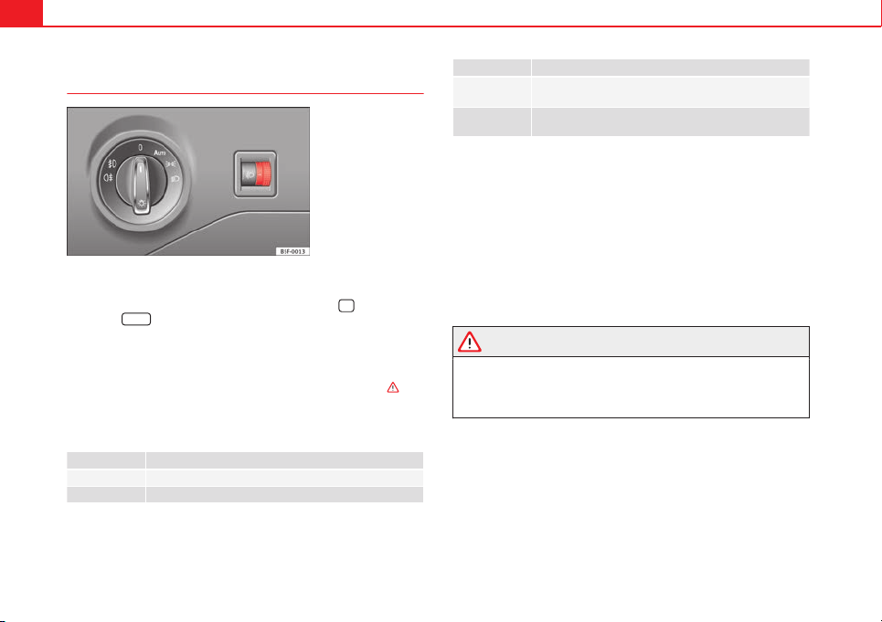
114 Lights and visibility
Headlight range control, lighting of the instrument panel
and controls
Fig. 62 Next to the
steering wheel: Head-
light range control
Lighting of the instrument panel and controls*
Depending on the model, lighting of the instrument panel and controls can
be adjusted in the Easy Connect system, using the button
and the func-
tion button
SETUP
⇒ page 81.
Headlight range control
The headlight range control ⇒ Fig. 62 is modified according to the value of
the headlight beam and the vehicle load status. This offers the driver opti-
mum visibility and the headlights do not dazzle oncoming drivers ⇒
.
The headlights can only be adjusted when the dipped beam is switched on.
To reset, turn switch ⇒ Fig. 62:
Value Vehicle load status
a)
– Two front occupants, luggage compartment empty
1 All seats occupied, luggage compartment empty
Value Vehicle load status
a)
2
All seats occupied, luggage compartment full With trailer
and minimum drawbar load
3
Driver only, luggage compartment full With trailer and
maximum drawbar load
a)
If the vehicle load does not correspond to those shown in the table, it is possible to select
intermediary positions.
Dynamic headlight range control
The control is not mounted in vehicles with dynamic headlight range con-
trol. The headlight range is automatically adjusted according to the vehicle
load status when the headlights are switched on.
Instrument panel lighting
In vehicles with the daytime driving light, the instrument panel lighting
switches on in dark conditions (for example, when passing through a tun-
nel). This reminds the driver to manually switch on the dipped beam, so
that the vehicle rear lights also switch on ⇒ page 109.
WARNING
Heavy objects in the vehicle may mean that the headlights dazzle and
distract other drivers. This could result in a serious accident.
● Adjust the light beam to the vehicle load status so that it does not
blind other drivers.
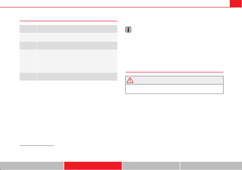
115Lights and visibility
Interior and reading lights
1)
Button/
Switch
Function
Switches interior lights off.
Switches interior lights on.
Switches door contact control on (central position).
The interior lights come on automatically when the vehicle is
unlocked, a door is opened or the key is removed from the ig-
nition.
The lights go off a few seconds after all the doors are closed,
the vehicle is locked or the ignition is switched on.
Turning the reading light on and off
Glove compartment and luggage compartment lighting
When opening and closing the glove compartment on the front passenger
side and the rear lid, the respective light will automatically switch on and
off.
Footwell lighting*
The lights in the footwell area below the dash (driver and front passenger
sides) will switch on when the doors are opened and will decrease in inten-
sity while driving. The intensity of these lights can be adjusted using the ra-
dio menu (see Easy Connect > Adjusting Lighting > Interior lighting
⇒ page 81).
Ambient light*
The ambient light in the door panel changes colour (white or red) depend-
ing on the driving mode. The intensity of these lights can be adjusted using
the radio menu (see Easy Connect > Adjusting Lights > Interior lighting
⇒ page 81).
Note
The reading lights switch off when the vehicle is locked using a key or after
several minutes if the key is removed from the ignition. This prevents the
battery from discharging.
Sun blind
Introduction
WARNING
Folded sun blinds can reduce visibility.
● Always store sun blinds and visors in their housing when not in use.
1)
Depending on the level of equipment fitted in the vehicle, LEDs can be used for the follow-
ing interior lights: front courtesy light, rear courtesy light, footwell light and sun visor light.
Safety First Operating instructions Practical Tips Technical specifications
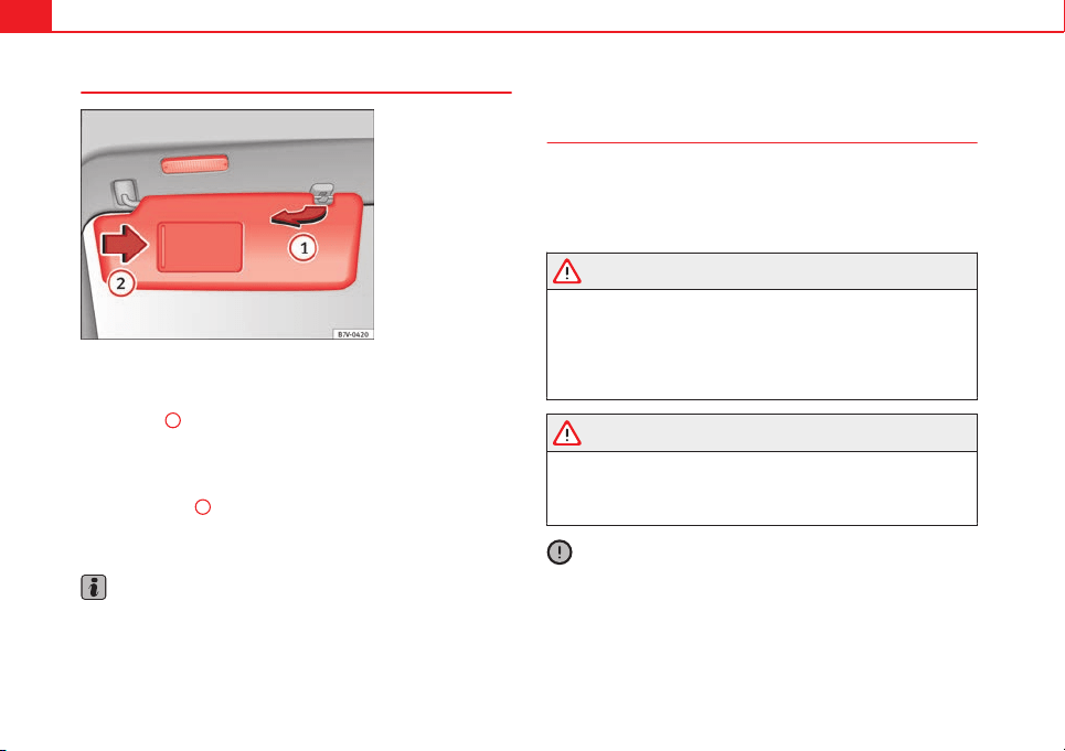
116 Lights and visibility
Sun visors
Fig. 63 Sun visor
Options for adjusting driver and front passenger sun visors:
● Lower by unfolding towards the windscreen.
● The sun visor can be pulled out of its mounting and turned towards the
door ⇒ Fig. 63
1
.
● Swing the sun visor towards the door, longitudinally backwards.
Vanity mirror light
There may be a vanity mirror, with a cover, on the rear of the sun visor. When
the cover is opened
2
a light comes on.
The lamp goes out when the vanity mirror cover is closed or the sun visor is
pushed back up.
Note
The light above the sun visor automatically switches off after a few minutes
in certain conditions. This prevents the battery from discharging.
Windscreen wiper system
Introduction
Additional information and warnings:
● Changing wheels round
● Heating, ventilation, cooling
● Caring for and cleaning the vehicle exterior
WARNING
If the water from the windscreen washer does not contain enough anti-
freeze, it may freeze on the windscreen, reducing forward visibility.
● In winter, ensure the windscreen washer contains enough anti-freeze.
● In cold conditions, you should not use the wash/wipe system unless
you have warmed the windscreen with the ventilation system. The anti-
freeze could freeze on the windscreen and reduce visibility.
WARNING
Worn or dirty wiper blades reduce visibility and increase the risk of acci-
dent and serious injury.
● Always replace damaged or worn blades or blades which do not clean
the windscreen correctly.
CAUTION
In icy conditions, always check that the wiper blades are not frozen to the
glass before using the wipers. In cold weather, it may help to leave the vehi-
cle parked with the wipers in service position ⇒ page 119.

117Lights and visibility
Control lamp
lights up Possible cause Solution
Windscreen wiper fluid level
too low
Top up the windscreen wiper
reservoir as soon as possible
⇒ page 121.
Several warning and control lamps should light up for a few seconds when
the ignition is switched on, signalling that the function is being verified.
They will switch off after a few seconds.
CAUTION
Failure to heed the control lamps and text messages when they appear may
result in faults in the vehicle.
Safety First Operating instructions Practical Tips Technical specifications
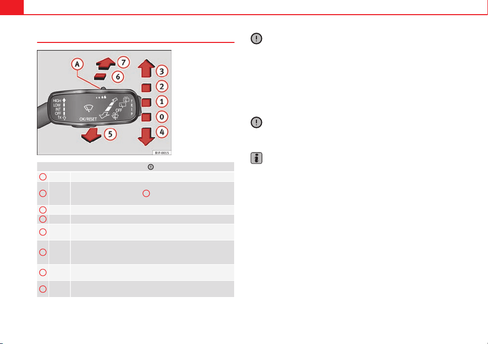
118 Lights and visibility
Window wiper lever
Fig. 64 Operating the
windscreen wiper and
rear wiper
Move the lever to the required position ⇒ :
0
OFF Windscreen wiper off.
1
INT
Windscreen wipers interval wipe.
Using the control ⇒ Fig. 64
A
adjust the interval (vehicles
without the rain sensor), or the sensitivity of the rain sensor.
2
LOW Slow wipe.
3
HIGH Continuous wipe.
4
1x
Brief press, short clean. Hold the lever down for more time to
increase the wipe frequency.
5
The windscreen washer function is activated by pushing the
lever forwards, and simultaneously the windscreen wipers
start.
6
Interval wipe for rear window. The rear wiper will wipe the win-
dow approximately every six seconds.
7
The windscreen washer function is activated by pressing the
lever, and the rear wiper starts simultaneously.
CAUTION
If the ignition is switched off with the windscreen wipers active, they com-
plete their wipe before returning to the rest position. Ice, snow and other
obstacles on the windscreen may damage the wiper and the windscreen
wiper motor.
● If necessary, remove snow and ice from the windscreen wipers before
starting your journey.
● Carefully lift the frozen windscreen wipers from the glass. SEAT recom-
mends a de-icer spray for this operation.
CAUTION
Do not switch on the windscreen wipers if the windscreen is dry. Cleaning
with the windscreen wipers while dry can cause damage.
Note
● The windscreen wipers will only function when the ignition is switched
on and the respective bonnet or rear lid are closed.
● The interval wipe speed varies according to the vehicle speed. The faster
the vehicle is moving, the more often the windscreen is cleaned.
● The rear wiper is automatically switched on when the windscreen wiper
is on and the car is in reverse gear.
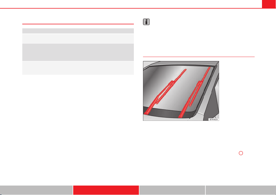
119Lights and visibility
Windscreen wiper functions
Windscreen wiper performance in different situations:
If the vehicle is at a stand-
still:
The activated position provisionally changes
to the previous position.
During the automatic wipe:
The air conditioner comes on for approxi-
mately 30 seconds in air recirculation mode
to prevent the smell of the windscreen wash-
er fluid entering the inside the vehicle.
For the interval wipe:
The intervals between wipes vary according
to the speed of the vehicle. The higher the
vehicle speed the shorter the intervals.
Heated windscreen washer jets
The heating only thaws the frozen jets, it does not thaw the water in the
washer hoses. The heated windscreen washer jets automatically adjust the
heat depending on the ambient temperature, when the ignition is switched
on.
Headlight wash/wipe system
The headlight washers/wipers clean the headlight lenses.
After the ignition is switched on, the first and every fifth time the wind-
screen washer is switched on, the headlights are also washed. Therefore,
the windscreen wiper lever should be pulled towards the steering wheel
when the dipped beam or main beam are on. Any incrusted dirt (such as in-
sects) should be cleaned regularly (e.g. when refuelling).
To ensure the headlight washers work correctly in winter, any snow which
has got into the bumper jet supports should be cleaned away. If necessary,
remove snow with an anti-icing spray.
Note
The wiper will try to wipe away any obstacles that are on the windscreen.
The wiper will stop moving if the obstacle blocks its path. Remove the ob-
stacle and switch the wiper back on again.
Windscreen wipers service position
Fig. 65 Wipers in service
position
The wiper arms can be raised when the wipers are in service position
⇒ Fig. 65. To place the windscreen wipers in the service position, proceed
as follows:
● The bonnet must be closed ⇒ page 209.
● Switch the ignition on and off.
● Press the windscreen wiper lever downwards briefly ⇒ Fig. 64
4
.
Before driving, always lower the wiper arms. Using the windscreen wiper
lever, the windscreen wiper arms return to their initial position.
Safety First Operating instructions Practical Tips Technical specifications
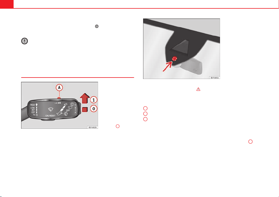
120 Lights and visibility
Lifting and returning windscreen wiper arms
● Place the wiper arms in the service position ⇒
.
● Only hold the wiper arms at the point where the blade is fixed.
CAUTION
● To prevent damage to the bonnet and the wiper arms, only leave them in
the service position.
● Before driving, always lower the wiper arms.
Rain sensor*
Fig. 66 Windscreen wip-
er lever: adjusting the
rain sensor
A
Fig. 67 Rain sensor sen-
sitive surface
The rain sensor controls the frequency of the windscreen wiper intervals,
depending on the amount of rain
⇒
. The sensitivity of the rain sensor can
be adjusted manually. Manual wipe
⇒
page 118
Move the lever to the required position
⇒
Fig. 66:
Rain sensor off.
Rain sensor on; automatic wipe if necessary.
Setting sensitivity level of rain sensor
– Set control to the right: highly sensitive.
– Set control to the left: less sensitive.
When the ignition is switched off and then back on, the rain sensor stays on
and starts operating again when the windscreen wipers are in position
1
and the vehicle is travelling at more than 16 km/h (10 mph).
Rain sensor modified behaviour
Possible causes of faults and mistaken readings on the sensitive surface
⇒
Fig. 67 of the rain sensor include:
0
1
A
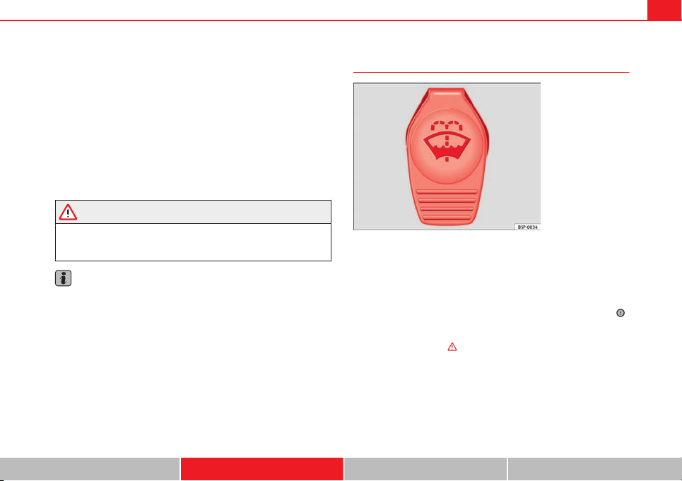
121Lights and visibility
● Damaged blades: A film of water on the damaged blades may lengthen
the activation time, reduce the washing intervals or result in a fast and con-
tinuous wipe.
● Insects: insects on the sensor may trigger the windscreen washer.
● Salt on roads: in winter, salt spread in the roads may cause an extra
long wipe when the windscreen is almost dry.
● Dirt: dry dust, wax, coating on glass (Lotus effect) or traces of detergent
(car wash) may reduce the effectiveness of the rain sensor or make it react
more slowly, later or not at all.
● Cracked windscreen: the impact of a stone will trigger a single wipe cy-
cle with the rain sensor on. Next the rain sensor detects the reduction in the
sensitive surface area and adapts accordingly. The behaviour of the sensor
will vary with the size of the damage caused by the stone.
WARNING
The rain sensor may not detect enough rain to switch on the wipers.
● If necessary, switch on the wipers manually when water on the wind-
screen obstructs visibility.
Note
● Clean the sensitive surface of the rain sensor regularly and check the
blades for damage ⇒ Fig. 67 (arrow).
● To remove wax and coatings, we recommend a window cleaner contain-
ing alcohol.
Checking and topping up the windscreen washer reservoir
with water
Fig. 68 In the engine
compartment: wind-
screen washer reservoir
top
Check the water level in the windscreen washer reservoir regularly and top
up as required.
● Open the bonnet
⇒
page 209.
● The washer reservoir is marked with the symbol on the lid
⇒
Fig. 68.
● Check there is enough water in the reservoir.
● To top up, mix water with a window cleaner recommended by SEAT
⇒
.
Please follow the instructions for use found on the packaging.
● In cold weather, a special antifreeze should also be added to prevent
the water from freezing
⇒
.
Safety First Operating instructions Practical Tips Technical specifications
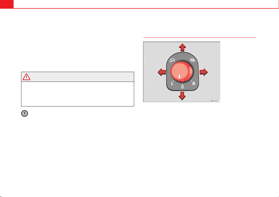
122 Lights and visibility
Recommended windscreen wipers
● For the hottest seasons we recommend summer G 052 184 A1 for clear
glass. Proportions of the mixture in the washer fluid tank: 1:100 (1 part con-
centrate per 100 parts water).
● All year round, G 052 164 A2 for clear glass. Approximate proportion of
the winter mixture, up to -18 °C (0 °F): 1:2 (1 part concentrate per 2 parts
water); otherwise, a 1:4 proportion of mixture in the washer fluid tank.
Reservoir capacity
The reservoir holds approximately 3 - 4 litres; in vehicles with headlight
washer, it is approximately 3 -6 litres.
WARNING
Never mix an unsuitable antifreeze or other similar additives with the
windscreen washer water. A greasy layer may be formed on the wind-
screen which will impair visibility.
● Use clean water with a window cleaner recommended by SEAT.
● If necessary, add a suitable antifreeze to the water in the reservoir.
CAUTION
● Do not mix cleaning products recommended by SEAT with other prod-
ucts. This could lead to flocculation and may block the windscreen washer
jets.
● When topping up service fluids, make absolutely certain that you fill the
fluids into the correct reservoirs. Using the wrong fluids could cause serious
malfunctions and engine damage!
Rear vision mirror
Adjusting the exterior mirrors
Fig. 69 Driver door: con-
trol for the exterior mirror
Turn the knob to the appropriate position:
– In these positions you can adjust the exterior mirrors (left or right) by
moving the control in the desired direction.
– The surfaces of the exterior mirrors are heated* depending on the
outside temperature, and on the equipment fitted in the vehicle.
– The exterior mirrors are retracted*.
Synchronized regulation of the exterior mirrors
● In the Settings - Convenience menu, select whether or not the exterior
mirrors should move in synchronisation
⇒
page 77.
● Turn the knob to position L.
● Adjust the left-hand exterior mirror. The right exterior mirror will be ad-
justed at the same time (synchronised).
L/R
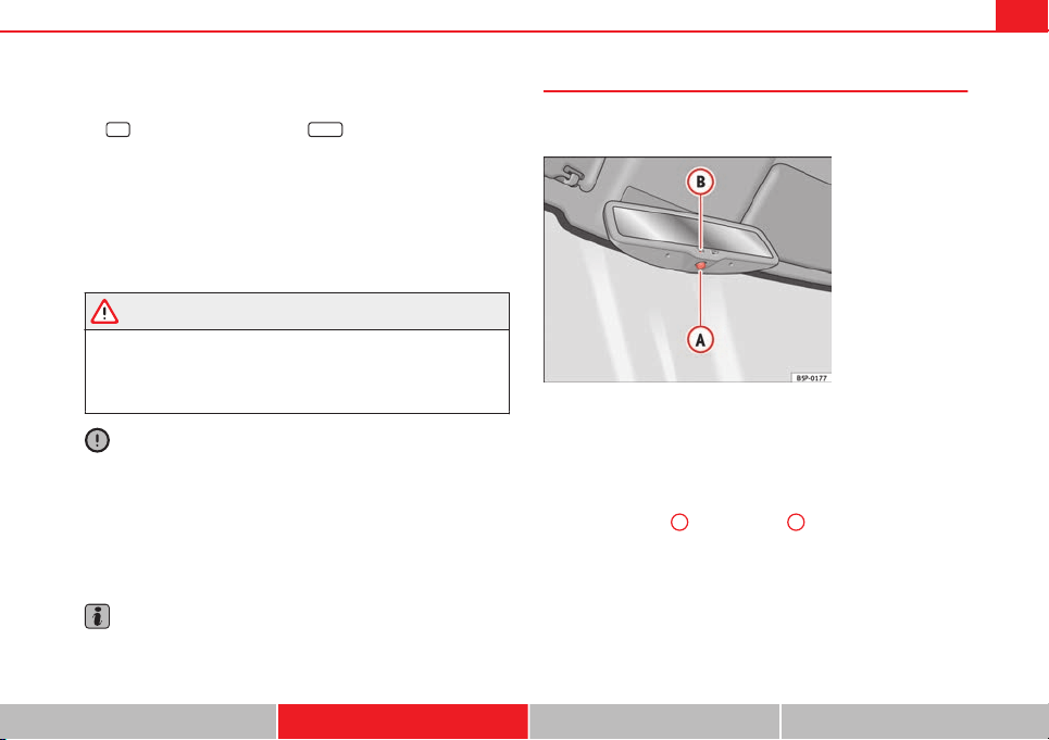
123Lights and visibility
● If necessary the right exterior mirror adjustment may need correcting.
Turn the knob to position R.
● In the Easy Connect system the exterior mirrors can be adjusted using
the
CAR
button and the function button
SETUP
.
Tilt function for front passenger exterior mirror*
The mirror can automatically tilt slightly to provide a better view of the kerb
when parking backwards. The control must be in the position R for this fea-
ture to be operational.
The mirror returns to its original position as soon as you drive forwards at
over 15 km/h (10 mph) or switch off the ignition. It also returns to its origi-
nal position if the position of the control is adjusted.
WARNING
Convex or wide-angle* exterior mirrors give a larger field of vision. How-
ever, they make objects look smaller and further away than they really
are. If you use these mirrors to estimate the distance to vehicles behind
you when changing lane, you could misjudge the distance. Risk of acci-
dent!
CAUTION
● If one of the mirror housings is knocked out of position (e.g. when park-
ing), the mirrors must first be fully retracted with the electric control. Do not
readjust the mirror housing by hand, as this will interfere with the mirror ad-
juster function.
● Before washing the vehicle in an automatic car wash, please make sure
to retract the exterior mirrors to prevent them from being damaged. Electri-
cally retractable exterior mirrors must NOT be folded in or out by hand. Al-
ways use the electrical power control.
Note
If the electrical adjustment should fail to operate, both of the mirrors can be
adjusted by hand by lightly pressing the edge of the mirror glass.
Anti-dazzle rear vision mirrors
Your vehicle is fitted with an interior rear vision mirror with a
manual or automatic control for anti-dazzle position.
Fig. 70 Interior rear vi-
sion mirror with automat-
ic setting for anti-dazzle
position
Interior rear vision mirror with manual setting for anti-dazzle
position
– Position the small lever of the lower edge of the mirror to face
towards the rear.
Anti-dazzle rear vision mirror with automatic setting*
– Press the button
A
. Warning lamp
B
will light up. Depending
on the amount of light incidence, the interior rear vision mirror
and the exterior* mirrors darken (e.g. headlight shining from
behind).
Safety First Operating instructions Practical Tips Technical specifications
124 Lights and visibility
WARNING
In the event that an automatic anti-dazzle rear vision mirror breaks, an
electrolyte fluid may leak. This could cause irritation to the skin, eyes
and respiratory organs. If you come into contact with this liquid, it must
be rinsed with large quantities of water. If necessary, get medial help.
CAUTION
In the event that an automatic anti-dazzle rear vision mirror breaks, an elec-
trolyte fluid may leak. This liquid attacks plastic surfaces. Clean the liquid
with a wet sponge as soon as possible.
Note
● If the light incident in the interior rear vision mirror is obstructed (e.g.
with the sun blind*), the anti-dazzle rear vision mirror with automatic set-
ting will not operate perfectly.
● When the interior lights are on or reverse gear engaged, the rear vision
mirrors do not darken with automatic adjustment for anti-dazzle position.
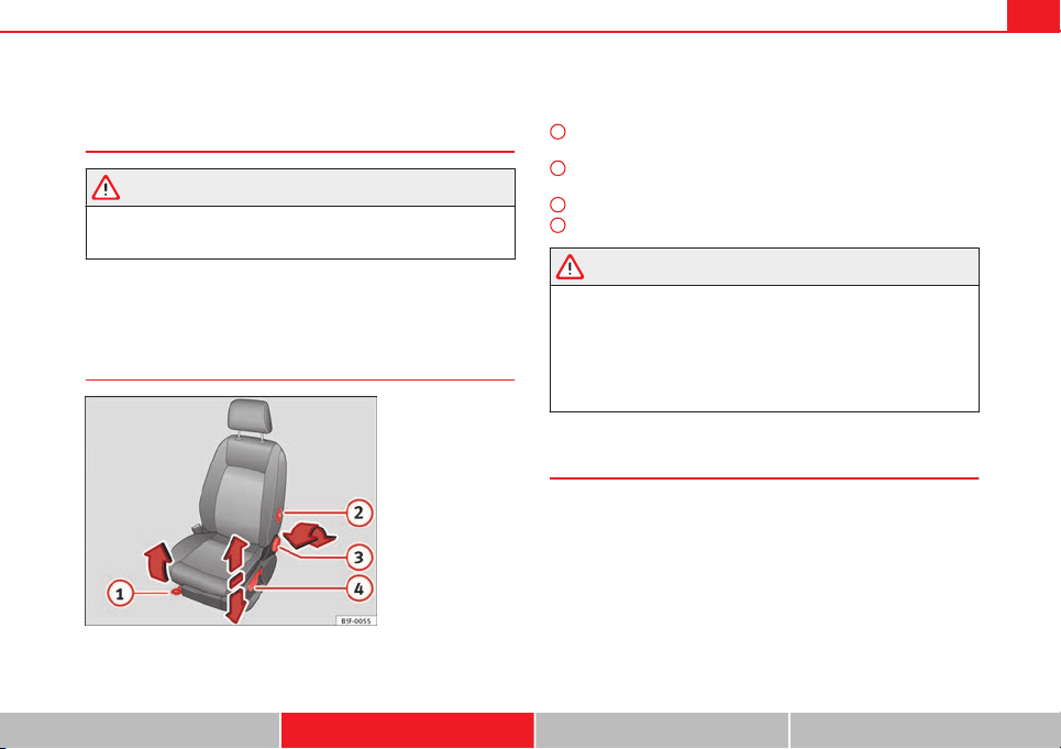
125Seats and storage
Seats and storage
General notes
WARNING
The Safe driving chapter contains important information, tips, sugges-
tions and warnings that you should read and observe for your own safety
and the safety of your passengers ⇒ page 7.
Front seats
Manual seat adjustment
Fig. 71 Front seats:
manual seat adjustment
Adjusting the seat forward/backward: pull the lever and move the seat
forwards or backwards.
Adjusting the lumbar support* : press the button in the corresponding
position.
Backrest lower/raise: turn the hand wheel.
Raise/lower the seat: Pull/push the lever.
WARNING
● Adjust the front seats only when the vehicle is stationary. Failure to
do so could result in an accident.
● Be careful when adjusting the seat height. Careless or uncontrolled
adjustment can cause injuries.
● The front seat backrests must not be reclined for driving. Otherwise,
seat belts and the airbag system might not protect as they should, with
the subsequent danger of injury.
Front centre armrest
The centre armrest can be adjusted to various levels.
Adjusting the centre armrest
– To adjust the tilt, lift the armrest from the starting position so
that it is engaged.
– To return the armrest to the starting position, remove the arm-
rest from the upper fixed position and lower it.
The armrest can be moved backwards and forwards.
1
2
3
4
Safety First Operating instructions Practical Tips Technical specifications
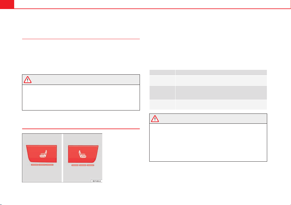
126 Seats and storage
Seat functions
Introduction
Additional information and warnings
● Adjusting the position of the seats ⇒ page 10
● Seat belts ⇒ page 19
● Airbag system ⇒ page 30
● Child seats (accessories) ⇒ page 47
WARNING
Inappropriate use of the seat functions can cause severe injuries.
● Assume the proper sitting position before your trip and remain in it
throughout. This also applies to the other occupants.
● Always keep hands, fingers, feet and other parts of the body away
from the operating radius and the adjustment of seats.
Seat heating
Fig. 72 In the centre
console: front seats heat-
ing switch
The seat cushions can be heated electrically when the ignition is switched
on. The backrest is also heated in some versions.
The seat heating should not be engaged in any of the following conditions:
● The seat is unoccupied.
● The seat has a covering.
● There is a child seat installed in the seat.
● The seat cushion is wet or damp.
● The indoor or outdoor temperature is greater than 25 °C (77 °F).
Function Using seat heating
To switch sys-
tem on:
Press the button or . Seat heating is switched on fully.
Adjusting the
heating out-
put:
Press the button or repeatedly until the desired inten-
sity level is reached.
To switch sys-
tem off:
Press the button or until all warning lamps switch off.
WARNING
People who, because of medications, paralysis or chronic diseases (e.g.
diabetes) cannot perceive pain or temperature, or have a limited percep-
tion thereof, may suffer burns to the back, buttocks or legs when using
seat heating, an occurrence that may entail a very lengthy recovery peri-
od or from which it may not be possible to recover fully. Seek medical ad-
vice if you have doubts regarding your health.
● People with a limit pain and temperature threshold must never use
seat heating.
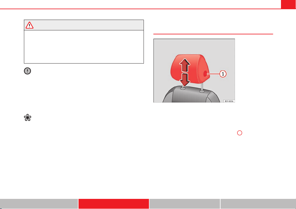
127Seats and storage
WARNING
If the fabric of the cushion is wet, this can adversely affect the operation
of the seat heating, increasing the risk of burns.
● Make sure the seat cushion is dry prior to using the seat heater.
● Do not sit on the seat with clothing that is wet or damp.
● Do not leave clothing that is wet or damp on the seat.
● Do not spill liquid on the seat.
CAUTION
● To avoid damaging the heating elements of the seat heating, please do
not kneel on the seat or apply sharp pressure at a single point to the seat
cushion and backrest.
● Liquids, sharps objects and insulating materials (e.g., covers or child
seats) can damage the seat heating.
● In the event of odours, switch off the seat heating immediately and have
the unit inspected by a specialised workshop.
For the sake of the environment
The seat heating should remain on only when needed. Otherwise, it is an
unnecessary fuel waste.
Head restraints
Fig. 73 Front seat: ad-
justment of the head re-
straint
Adjust the head restraint so that the top of the head restraint is lev-
el with the top of your head. When this is not possible, try to get as
close as possible to this position.
– Grasp the sides of the head restraint with both hands and move
it up/down (to lower you must press button
1
) until you see it
engage.
Safety First Operating instructions Practical Tips Technical specifications
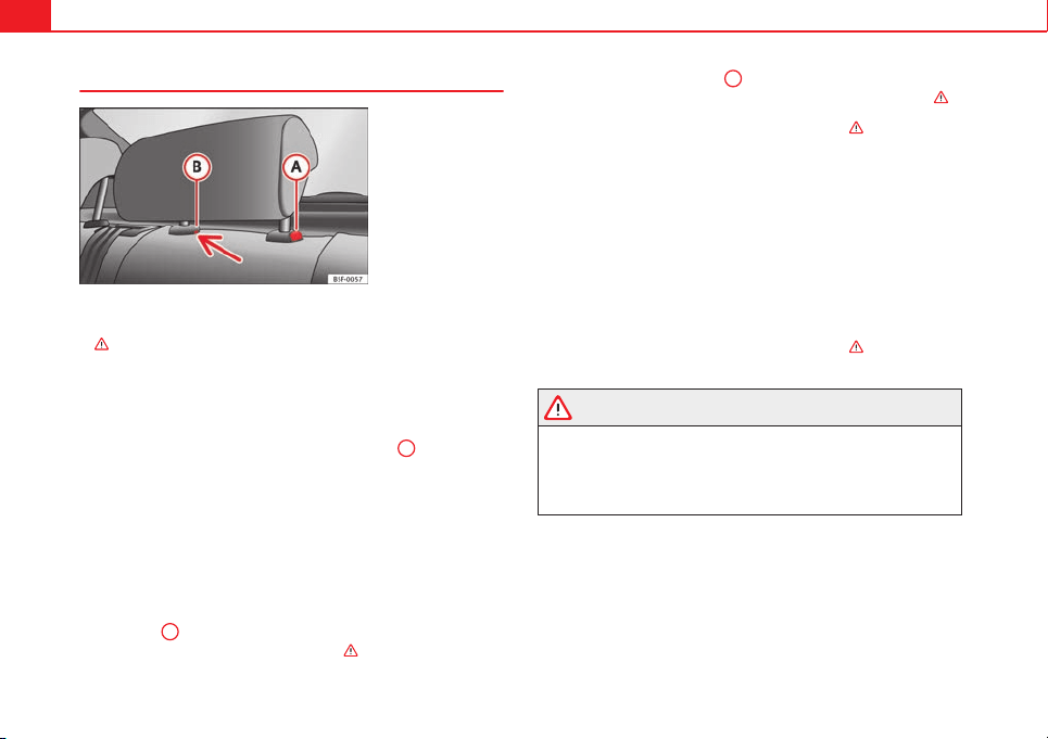
128 Seats and storage
Rear head restraints
Fig. 74 Rear centre head
restraint: release point
When transporting people in the back seat, place the head re-
straints of the occupied seats at a minimum of the next socket up
⇒
.
Adjusting the head restraints
– To set the head restraint higher, grasp the sides with both
hands and move it upwards, until you see it engage.
– To set the head restraint lower down, press the
A
⇒ Fig. 74
button and move it downwards.
Removing the head restraint
To remove the head restraint, the corresponding backrest must be
partially folded forward.
– Unlock the backrest ⇒ page 132.
– Move the head restraint upwards until it arrives to the top.
– Press the
A
⇒ Fig. 74 button while at the same time removing
the head restraint from the backrest ⇒
.
– Insert a screwdriver in the
B
position of the hole while at the
same time removing the head restraint from the backrest ⇒
.
– Move the backrest until it engages properly ⇒
in Increase ca-
pacity of luggage compartment on page 133.
Fitting the head restraint
To mount the external head restraints, the corresponding backrest
must be partially folded forward.
– Unlock the backrest ⇒ page 132.
– Insert the head restraint bars into the guides until they percept-
ibly engage. It should not be possible to remove the head re-
straint from the backrest.
– Move the backrest until it engages properly ⇒
in Increase ca-
pacity of luggage compartment on page 133.
WARNING
● Please observe the general notes.
● Remove the rear head restraints only when it is necessary for the
placement of a child seat ⇒ page 47. After removing a child seat, remount
the head restraint immediately. Travelling with the head restraints re-
moved or improperly adjusted increases the risk of severe injuries.
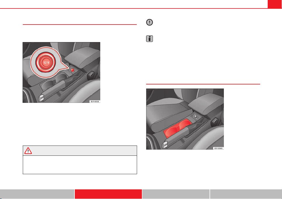
129Seats and storage
Power socket
Electrical equipment can be connected to the 12 volt power
socket.
Fig. 75 Centre console:
front/rear 12-volt power
socket
– Remove the connector located in the centre console of the pow-
er socket ⇒ Fig. 75.
– Insert the plug of the electrical appliance into the power socket.
Electrical equipment can be connected to the 12 volt power socket. The ap-
pliances connected to each power socket must not exceed a power rating of
120 Watt.
WARNING
The power socket works only when the ignition is on. Improper use may
cause serious injury or even fire. Children should therefore not be left in
the vehicle, unattended, if the button is also left behind. Otherwise there
is a possibility that they may be injured.
CAUTION
Always use the correct type of plugs to avoid damaging the sockets.
Note
The use of electrical appliances with the engine switched off will cause a
battery discharge.
Storage
Drink holders
Fig. 76 Centre console:
Front drink holders
Front drink holders
– Place drinks in the holder ⇒ Fig. 76. Placement of two drinks is
possible. There is also the possibility of placing larger plastic
bottles in the trims of the doors.
Safety First Operating instructions Practical Tips Technical specifications
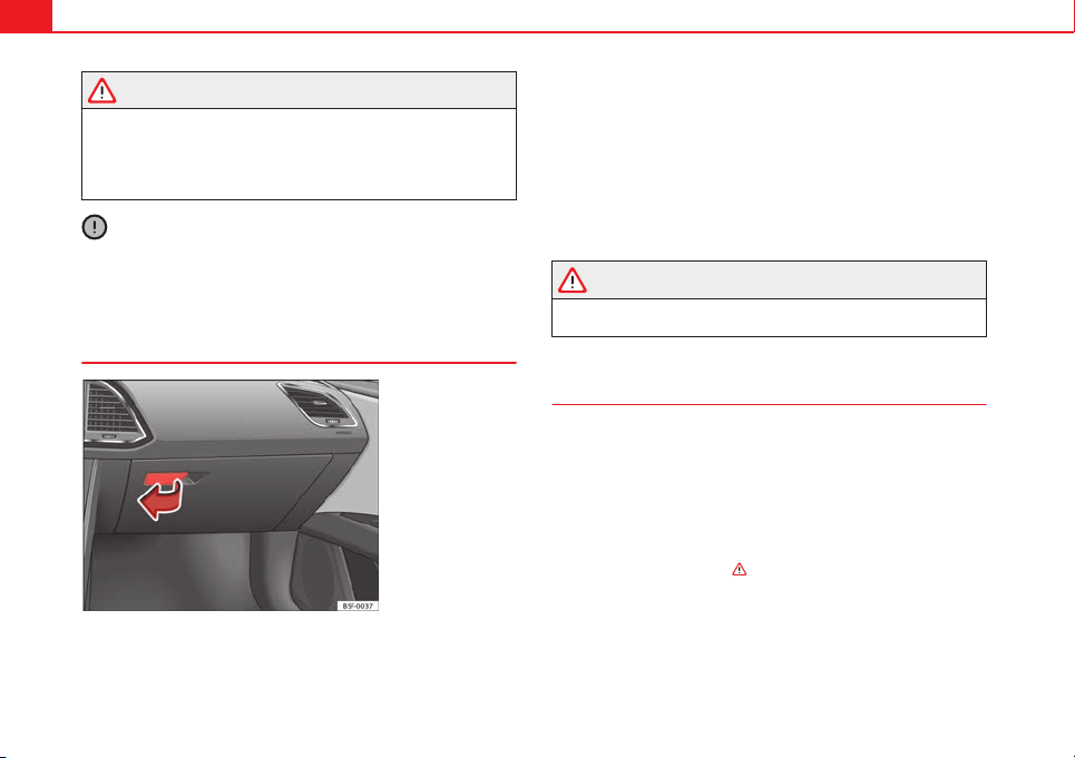
130 Seats and storage
WARNING
● Do not place any hot drinks in the drink holder while the vehicle is
moving. Hot drinks could spill and cause burns, which may cause an acci-
dent.
● Do not use hard china cups or glasses. These could cause injury in the
event of an accident.
CAUTION
You should avoid putting open drinks containers in the cup holders. The
drinks could otherwise spill over and cause damage to e.g. the electrical
equipment or the seat covers.
Glove compartment
Fig. 77 Glove compart-
ment
Open/close
– To open the glove compartment, pull the handle in the direction
of the arrow.
– To close the glove compartment, move the cover upwards until
it engages.
The CD-ROM reader* for the SEAT navigation system* is found in the glove
compartment. Separate operating instructions are enclosed for this equip-
ment in the corresponding Instruction Manual.
WARNING
The cover of the glove compartment should always be closed while driv-
ing. Failure to do so could result in an accident.
Other storage compartments
You will find more object holders, compartments and supports in other
parts of the vehicle:
● In the top of the glove compartment in vehicles that do not have a CD
reader. The load must not exceed 1.2 kg.
● In the centre console under the centre armrest*.
● In the driver side panel there is a removable box for access to fuses and
relays. The load of the compartment should not exceed 0.2 kg.
● Coat hooks in the pillar B ⇒
.
● Other storage compartments are found in the rear seat, to the left and
the right of the seats.
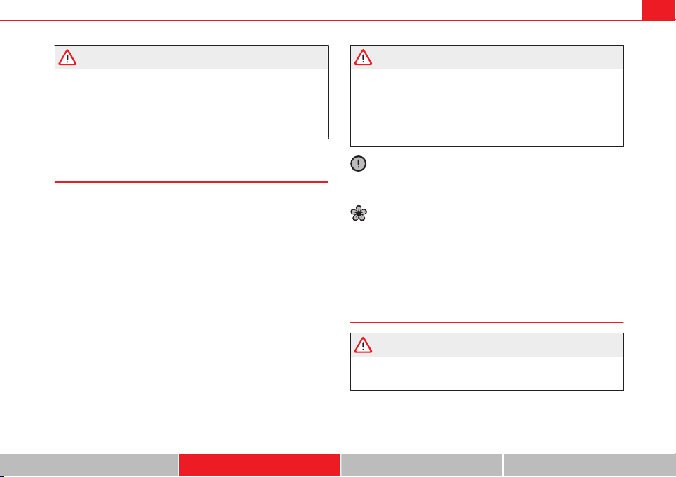
131Seats and storage
WARNING
● Please make sure that any items of clothing hanging from the coat
hooks do not obstruct your view to the rear.
● The coat hooks should only be used for lightweight clothing. Do not
leave any heavy or sharp objects in the pockets.
● Do not use clothes hangers to hang up the clothing, as this could in-
terfere with the function of the head-protection airbags.
Roof carrier
Note the following points if you intend to carry loads on the roof:
● In your car only certain roof carriers should be used. Roof carriers are the
basis of a complete roof carrier system. To transport luggage and sports
equipment, additional structures/transport systems are needed. We recom-
mend roof carriers and structures from the SEAT accessories programme.
● When mounting the roof carrier, be sure to mount only on the points al-
ready provided on the roof. The front and rear attachment points are only
visible when the doors are open.
● The maximum permissible roof load for your vehicle is 75 kg. The load
limit applies to the combined weight of the roof carrier, the structures, and
load itself. However, check the load permitted by the specific loading sys-
tem being used. Permissible axle weight and permissible total weight for
your vehicle ⇒ page 267.
WARNING
● Take note of the mounting instructions for the roof carrier system. If
the carrier system and the roof load are not properly secured, items of
luggage could fall from the vehicle and cause an accident.
● When you use a roof carrier system the style of driving changes due
to a shift of emphasis and the larger surface area exposed to wind drag,
which could cause an accident. Therefore, it is essential to adjust your
speed and driving style accordingly, to avoid accidents.
CAUTION
Check that when the rear lid is open, it does not touch loads carried on the
roof. When a roof carrier is fitted, DO NOT open the panoramic roof*.
For the sake of the environment
Greater aerodynamic drag increases fuel consumption. For this reason you
should always take off the roof carrier when it is not in use.
Luggage compartment
General notes
WARNING
The Safe driving chapter contains important information, tips, sugges-
tions and warnings that you should read and observe for your own safety
and the safety of your passengers ⇒ page 7.
Safety First Operating instructions Practical Tips Technical specifications
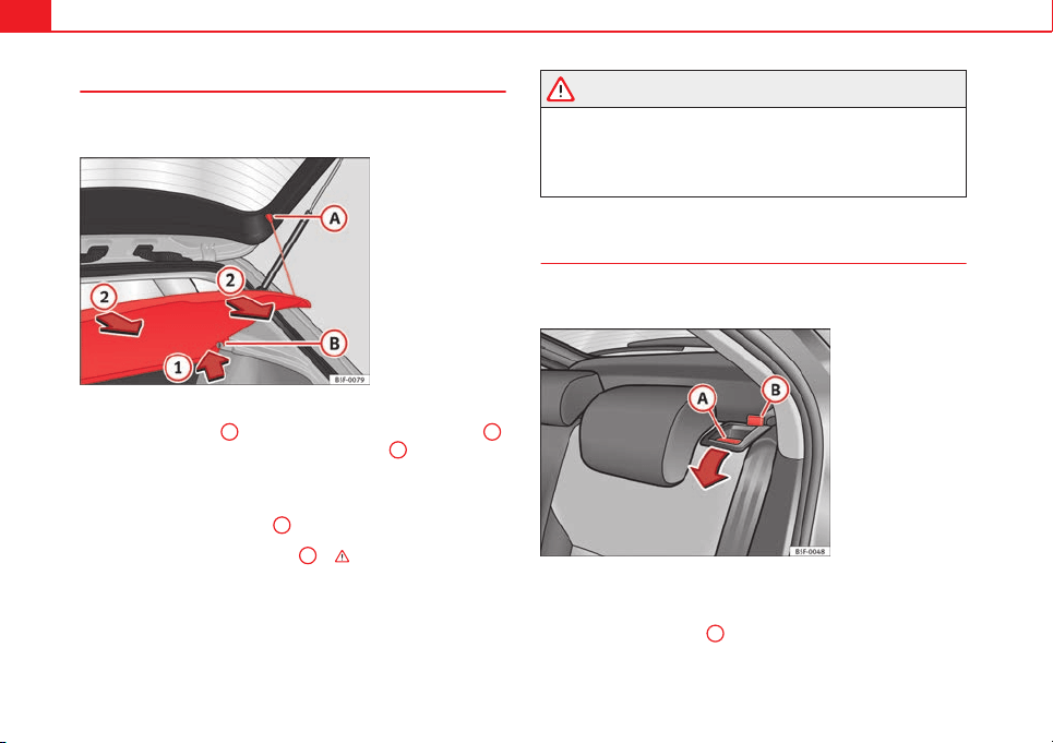
132 Seats and storage
Luggage compartment cover
The luggage compartment cover blocks the view into the
luggage compartment.
Fig. 78 Rear lid open
with the luggage com-
partment cover
Removing
– Remove the straps
A
and unfasten the cover of the support
B
by pressing upwards in the direction of arrow
1
.
Fitting
– Insert the cover horizontally so that it coincides with the “plate”
on the axis of the supports
B
and press down until it engages.
– Attach the straps to the rear lid
A
⇒ .
WARNING
● The luggage compartment cover must always be fixed properly (risk
of accident).
● The luggage compartment cover should not be used as a storage
shelf. Articles placed on this cover could cause injury to vehicle occu-
pants in an accident or if the brakes are applied suddenly.
Increase capacity of luggage compartment
The backrests can be folded forward individually or togeth-
er.
Fig. 79 Backrest release
lever
Folding the backrest forwards
– Slide the head restraint(s) downwards
⇒
page 128.
– Press the release lever
A
in the direction indicated (arrow).
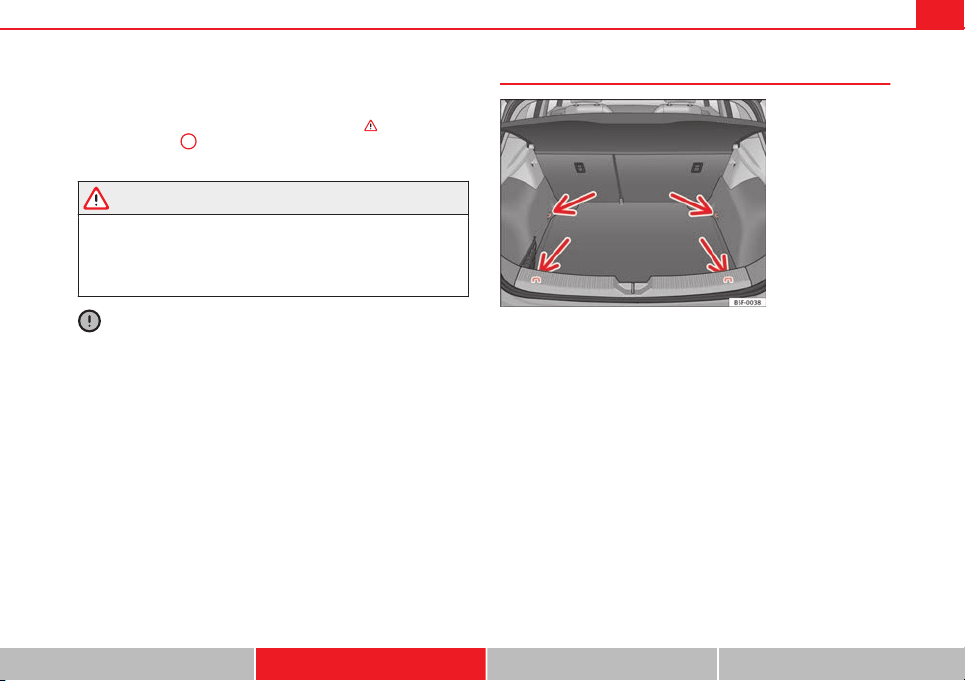
133Seats and storage
– Fold the backrest forwards.
Returning the backrest to its upright position
– Move the backrest until it engages properly ⇒
. The red mark-
ing on the tab
B
should no longer be visible when the backrest
is properly secured.
WARNING
● Make sure that the rear backrest is securely locked in position so that
the seat belt can provide proper protection on the centre rear seat.
● The rear backrest must always be securely latched so that objects
stored in the luggage compartment will not fly forward through the inte-
rior during sudden braking.
CAUTION
● With the backrest inclined there is a danger of damaging the rear head
restraints when adjusting the front seats backwards.
● When returning the backrest to an upright position, make sure that the
side seat belts are not caught up and damaged in the catches for the back-
rest.
Fastening rings*
Fig. 80 Location of fas-
tening rings in luggage
compartment
– Secure the load using the fastening rings -arrows-.
– Please refer to the safety notes ⇒ page 17.
Safety First Operating instructions Practical Tips Technical specifications
134 Air conditioning
Air conditioning
Heating, ventilation, cooling
Introduction
Viewing Climatronic information
On the screen of Climatronic control unit and on the screen of the factory-
fitted Easy Connect system, the theoretical values of the temperature zones
are shown.
The unit of temperature measurement can be changed in the Easy Connect
system.
Dust and pollen filter
The dust and pollen filter with its activated charcoal cartridge serves as a
barrier against impurities in the air taken into the vehicle interior.
The dust and pollen filter must be changed regularly so that air conditioner
performance is not adversely affected.
If the filter loses efficiency prematurely due to use in areas with very high
levels of air pollution, the filter must be changed more frequently than sta-
ted in the Service Schedule.
Additional information and warnings:
● Easy Connect system
● Seat functions
● Windscreen wipers and washers
● Caring for and cleaning the vehicle exterior
WARNING
Reduced visibility through the windows increases the risk of serious acci-
dents.
● Always ensure that all windows are free of ice and snow, and that
they are not fogged, so as to maintain good visibility of everything out-
side.
● The maximum heat output required to defrost windows as quickly as
possible is only available when the engine has reached its normal run-
ning temperature. Only drive when you have good visibility.
● Always ensure that you use the heating system, fresh air system, air
conditioner and the heated rear window to maintain good visibility to the
outside.
● Never leave the air recirculation on for a long period of time. If the
cooling system is switched off and air recirculation mode switched on,
the windows can mist over very quickly, considerably limiting visibility.
● Switch air recirculation mode off when it is not required.
WARNING
Stuffy or used air will increase fatigue and reduce driver concentration
possibly resulting in a serious accident.
● Never leave the fresh air fan turned off or use the air recirculation for
long periods of time; the air in the vehicle interior will not be refreshed.
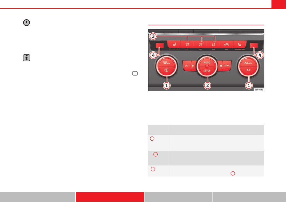
135Air conditioning
CAUTION
● Switch the air conditioner off if you think it may be broken. This will
avoid additional damage. Have the air conditioner checked by a specialised
workshop.
● Repairs to the air conditioner require specialist knowledge and special
tools. SEAT recommends visiting a SEAT Official Service.
Note
● When the cooling system is turned off, air coming from the outside will
not be dried. To prevent fogging of the windows, SEAT recommends leaving
the cooling system (compressor) turned on. To do this, press the button
.
The button lamp should light up.
● The maximum heat output required to defrost windows as quickly as
possible is only available when the engine has reached its normal running
temperature.
● Keep the air intake slots in front of the windscreen free of snow, ice and
leaves to ensure heating and cooling are not impaired, and to prevent the
windows from misting over.
Air conditioner controls
Fig. 81 In the centre console: Climatronic controls
To switch a function on or off, press the appropriate button. Press the but-
ton again to switch off the function.
The LED on each control lights up to indicate that the respective function of
a control has been switched on.
Control but-
ton
Additional information. Climatronic.
1
Temper-
ature
...
The left and right sides can be adjusted separately. Rotate
the control to adjust the temperature accordingly.
2
Fan
The power of the fan is automatically adjusted. The fan is al-
so adjusted manually by turning the control.
3
Air dis-
tribution
The airflow adjusts automatically for comfort. You can also
switch it on manually using the buttons
3
.
Safety First Operating instructions Practical Tips Technical specifications
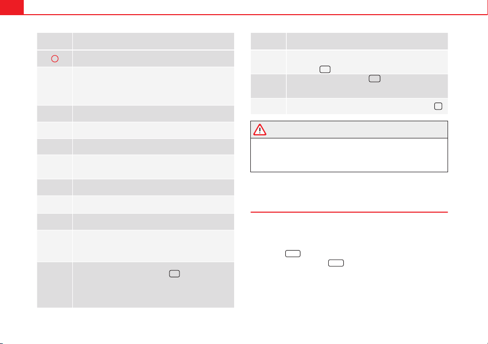
136 Air conditioning
Control but-
ton
Additional information. Climatronic.
4
Indications on the temperature display screen selected for
the right and left sides.
Defrost function. The air drawn in from outside the vehicle is
directed at the windscreen and air recirculation is automati-
cally switched off. To defrost the windscreen more quickly,
the air is dehumidified at temperatures over approximately
+3 °C (+38 °F) and the fan runs at maximum output.
The air is directed at the chest of driver and passengers by
the dash panel air vents.
Air distribution towards the footwell.
Upward air distribution.
Heated rear window: this only works when the engine is run-
ning and switches off automatically after a maximum of 10
minutes.
Air recirculation ⇒ page 141.
Buttons for seat heating ⇒ page 126.
Press the button to switch on or off the cooling system.
Press the button to make maximum cooling capacity availa-
ble. The recirculation of air and the cooling system turn on
automatically and air distribution adjusts automatically to
the position .
Transfer the driver side temperature settings to the passen-
ger side: when the button lamp is lit
, the temperature
settings on the driver side also apply to the passenger side.
Press the button or the temperature control on the passenger
side in order to change the temperature on that side. The
button lamp is lit.
Control but-
ton
Additional information. Climatronic.
Automatic adjustment of temperature, fan, and air distribu-
tion. Press the button to switch on the function. The button
will light up
.
When the configuration button
is pressed the air condi-
tioner management menu will be shown on the Easy Connect
system screen.
Switching
off
Turn the fan control to the 0 position or press the button
.
WARNING
Stuffy or used air will increase fatigue and reduce driver concentration
possibly resulting in a serious accident.
● Never leave the fresh air fan turned off or use the air recirculation for
long periods of time; the air in the vehicle interior will not be refreshed.
Operating by using the Easy Connect* system (valid for
Radio Entry)
In the Easy Connect system it is also possible to perform various adjust-
ments to the Climatronic.
Open the air conditioner menu
● Press the
Setup
button
● ALTERNATIVELY: press the
MENU
button in Easy Connect. With the rotat-
ing switch select the air conditioner menu and open it.
On the screen you can see and change the current settings, for example, the
temperature set for the driver side and for that of the passenger.
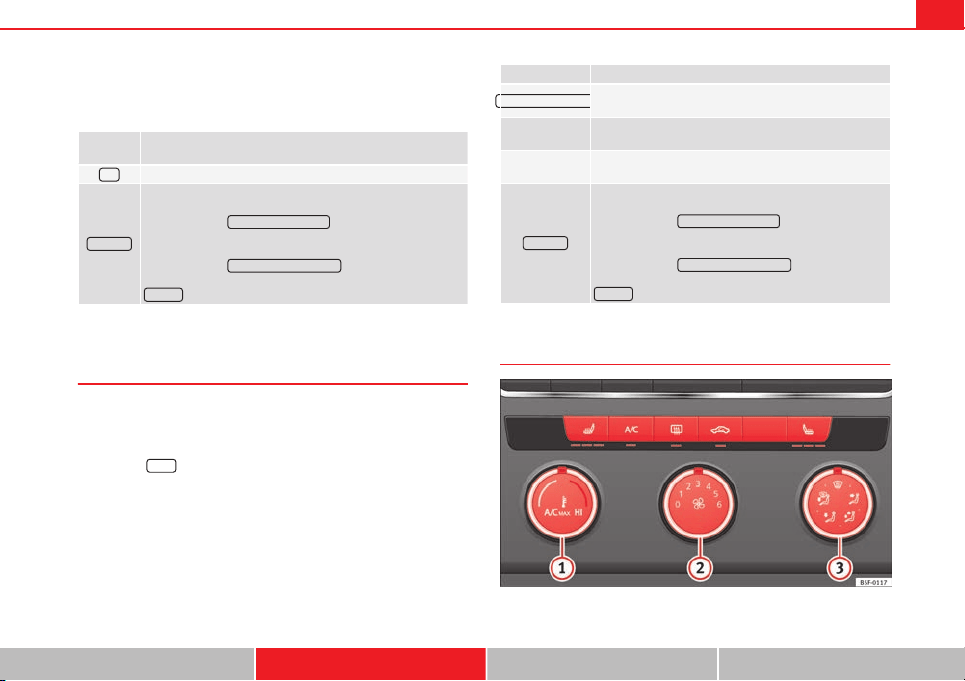
137Air conditioning
To switch a function on or off, or to select a submenu, you must press the
corresponding function button.
For more information about functions ⇒ page 79.
Function
button
Function
OFF
Switch off and switch on the Climatronic.
SETTINGS
The air conditioning settings submenu is opened. It is possi-
ble to make the following adjustments:
Function button
Air conditioning profile.
: to adjust the level of the
fan in AUTO mode. You can choose between low, medium and
high.
Function button
Automatic air recirculation
to switch on and off au-
tomatic air recirculation ⇒ page 141.
BACK
function button to close the submenu.
Operating by using the Easy Connect* system (valid for
Standard Radio)
In the Easy Connect system it is also possible to perform various adjust-
ments to the Climatronic.
Open the air conditioner menu
● Press the
Setup
button
On the top of the screen you can see and change the current settings, such
as, for example, the temperature set for the driver side and for that of pas-
senger. Temperatures up to +22 ° C (+72 ° F) are shown with blue arrows,
and temperatures over +22 ° C (+72 ° F) with red arrows.
To switch a function on or off, or to select a submenu, you must press the
corresponding function button.
Function button Function
Air conditioning profile
Adjust the fan level in AUTO mode. You can choose be-
tween low, medium and high.
Climatronic is switched off.
Climatronic is switched on.
SETTINGS
The air conditioning settings submenu is opened. It is
possible to make the following adjustments:
Function button
Air conditioning profile.
: to adjust the level
of the fan in AUTO mode. You can choose between low,
medium and high.
Function button
Automatic air recirculation
to switch on and
off automatic air recirculation ⇒ page 141.
BACK
function button to close the submenu.
Manual air conditioning controls
Fig. 82 In the centre console: Manual air conditioning controls
Safety First Operating instructions Practical Tips Technical specifications
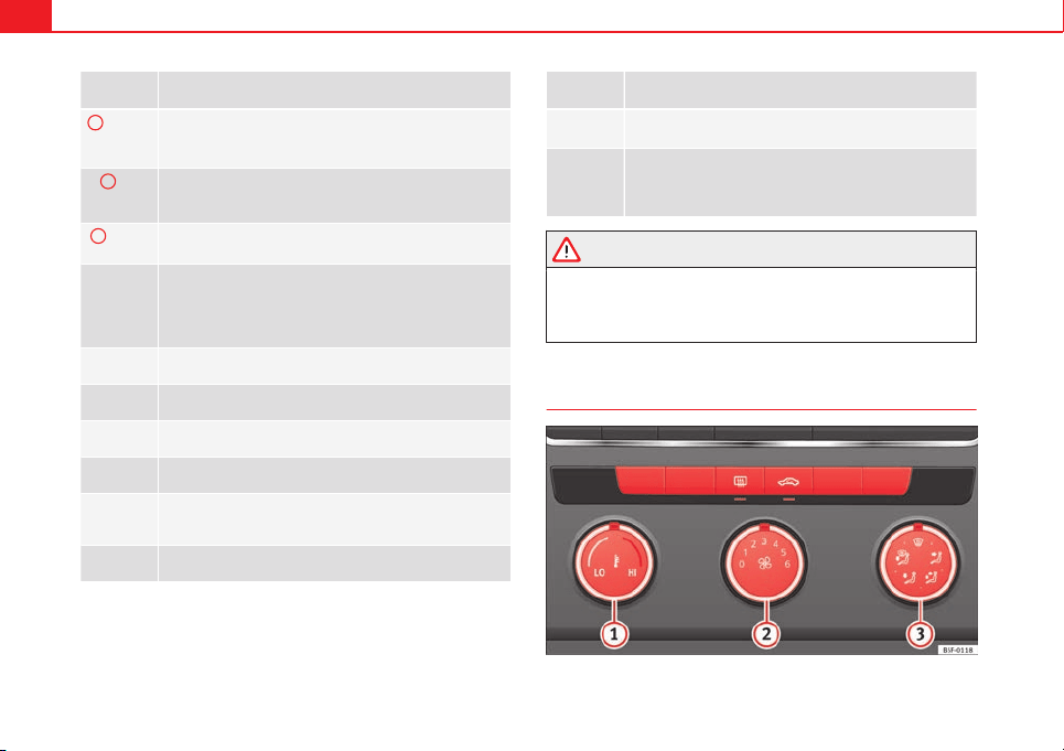
138 Air conditioning
Control but-
ton
Additional information. Manual air conditioning system.
1
Temper-
ature
...
Rotate the control to set the temperature accordingly.
2
Fan
Setting 0: fan and manual air conditioning switched off, level
6: maximum fan level
3
Air dis-
tribution
Rotate the continuous control to direct the airflow to the de-
sired area.
Defrost function. The airflow is directed at the windscreen. In
this position, air recirculation is automatically switched off or
is not switched on. Increase the fan power to clear the wind-
screen of condensation as soon as possible. To dehumidify
the air, the cooling system will automatically switch on.
The air is directed at the chest of driver and passengers by
the dash panel air vents.
Distribution of air towards the chest and the footwell area.
Air distribution towards the footwell.
Air distribution towards the windscreen and the footwell.
Heated rear window: this only works when the engine is run-
ning and switches off automatically after a maximum of 10
minutes.
Air recirculation ⇒ page 141.
Control but-
ton
Additional information. Manual air conditioning system.
Buttons for seat heating ⇒ page 126.
Turn the control to the position to make maximum
cooling capacity available. Air recirculation and the cooling
system are turned on automatically.
WARNING
Stuffy or used air will increase fatigue and reduce driver concentration
possibly resulting in a serious accident.
● Never leave the fresh air fan turned off or use the air recirculation for
long periods of time; the air in the vehicle interior will not be refreshed.
Heating system and fresh air controls
Fig. 83 In the centre console: heating system and fresh air controls
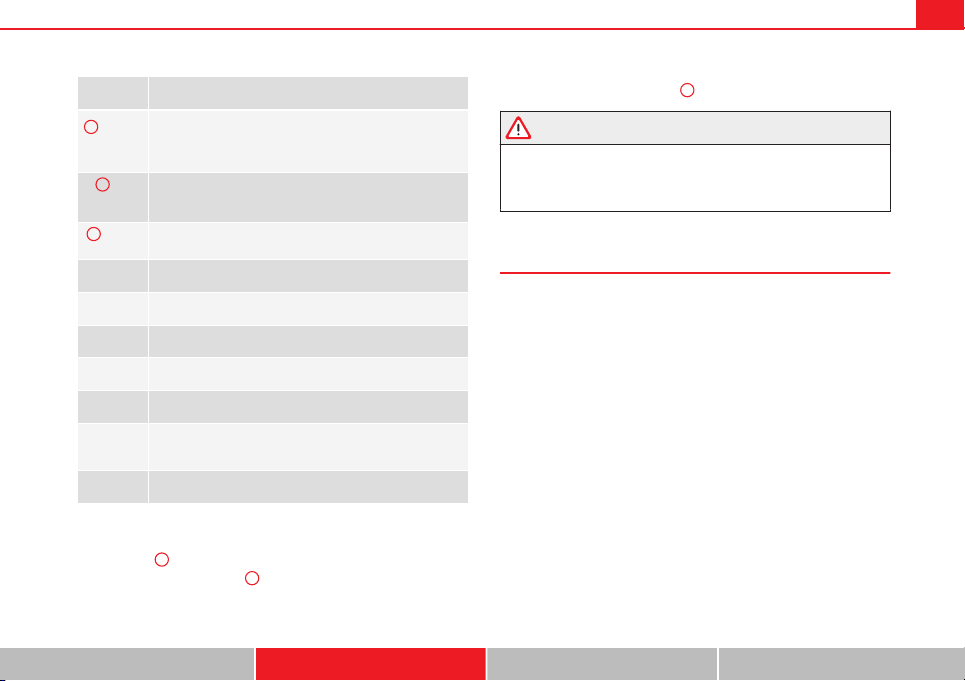
139Air conditioning
Control but-
ton
Additional information. Heating and fresh air system
1
Temper-
ature
...
Rotate the control to adjust the temperature accordingly. The
desired temperature for the interior cannot be lower than
that of the exterior air temperature, as the heating and fresh
air system cannot cool or dehumidify the air.
2
Fan
Setting 0: fan, heating and fresh air systems switched off,
level 6: maximum fan level.
3
Air dis-
tribution
Rotate the continuous control to direct the airflow to the de-
sired area.
The airflow is directed at the windscreen.
The air is directed at the chest of driver and passengers by
the dash panel air vents.
Distribution of air towards the chest and the footwell area.
Air distribution towards the footwell.
Air distribution towards the windscreen and the footwell.
Heated rear window: this only works when the engine is run-
ning and switches off automatically after a maximum of 10
minutes.
Air recirculation ⇒ page 141.
Setting for conditions of optimal visibility
● Disable air recirculation mode.
● Set the fan
2
to setting 1 or 2.
● Turn the temperature control
1
to the desired position.
● Open and direct all the air outlets in the dash panel.
● Turn the air distribution control
3
to the desired position.
WARNING
Stuffy or used air will increase fatigue and reduce driver concentration
possibly resulting in a serious accident.
● Never leave the fresh air fan turned off or use the air recirculation for
long periods of time; the air in the vehicle interior will not be refreshed.
Instructions for use of the air conditioner
The interior cooling system only works when the engine is running and fan
is switched on.
The air conditioner operates most effectively with the windows and the pan-
oramic sliding sunroof closed. However, if the vehicle has heated up after
standing in the sun for some time, the air inside can be cooled more quickly
by opening the windows and the panoramic sliding sunroof briefly.
Setting for conditions of optimal visibility
When the air conditioning is switched on, the temperature and the air hu-
midity in the vehicle interior drop. Hence, when the outside air humidity is
high, the windows do not mist over and comfort for the vehicle occupants is
improved:
With manual air conditioning
● Switch off air recirculation.
● Set the fan to the required setting.
● Turn the temperature control to the centre position.
● Open and direct all the air outlets in the dash panel.
Safety First Operating instructions Practical Tips Technical specifications
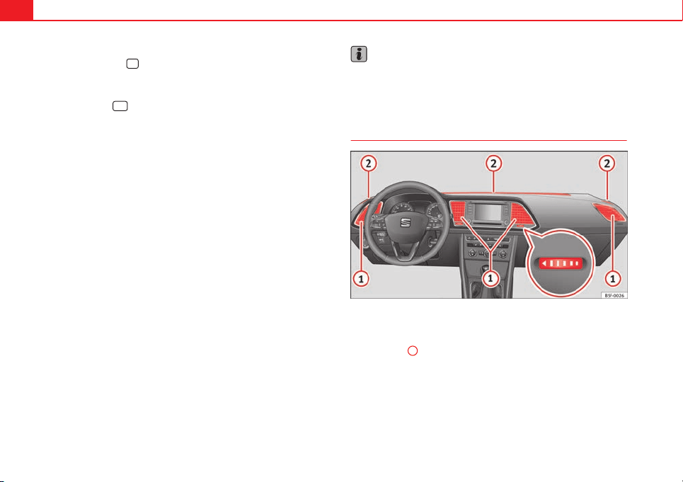
140 Air conditioning
● Turn the air distribution control to the required position.
● Press the button
to switch on the cooling system. The button will
light up.
With Climatronic
● Press button
.
● Set the temperature to +22 °C (+72 °F).
● Open and direct all the air outlets in the dash panel.
Climatronic: change the temperature unit on the screen of the radio or on
the factory-fitted navigation system
Changing the temperature display from Celsius to Fahrenheit on radio or on
the factory-fitted navigation system is done using the menu on the instru-
ment panel ⇒ page 73.
The cooling system cannot be activated
If the air conditioning system cannot be switched on, this may be caused by
the following:
● The engine is not running.
● The fan is switched off.
● The air conditioner fuse has blown.
● The outside temperature is lower than approximately +3 °C (+38 °F).
● The air conditioner compressor has been temporarily switched off be-
cause the engine coolant temperature is too high.
● Another fault in the vehicle. Have the air conditioner checked by a speci-
alised workshop.
Special Characteristics
If the humidity and temperature outside the vehicle are high, condensation
can drip off the evaporator in the cooling system and form a pool under-
neath the vehicle. This is normal and does not indicate a leak!
Note
After starting the engine, any residual humidity in the air conditioner could
mist over the windscreen. Switch on the defrost function as soon as possi-
ble to clear the windscreen of condensation.
Air vents
Fig. 84 On the dash panel: air vents
Air vents
To ensure proper heating, cooling and ventilation in the vehicle interior, air
vents ⇒ Fig. 84
1
should remain open.
● Turn the corresponding thumbwheel (detail) in the required direction to
open and close the air vents. When the thumbwheel is in the position, the
corresponding air vent is closed.
● Change the air direction using the ventilation grille lever.
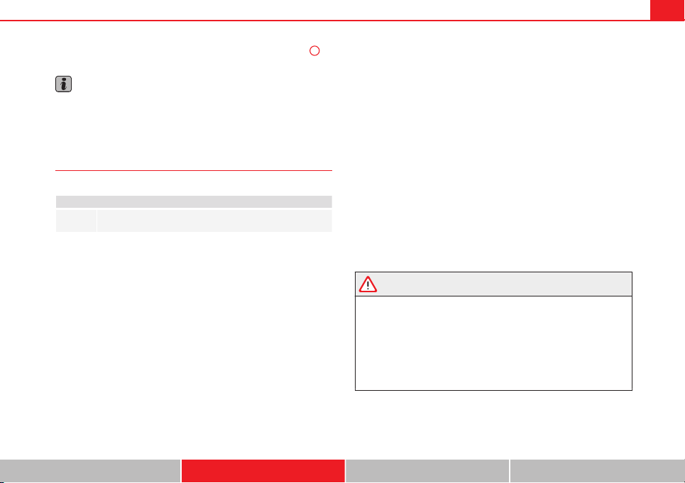
141Air conditioning
There are other additional, non-adjustable air vents in the dash panel
2
, in
the footwell and in the rear area of the interior.
Note
Never place food, medicines or other heat-sensitive objects close to the air
vents. Food, medicine and other heat or cold sensitive objects may be dam-
aged or made unsuitable for use by the air coming from the air vents.
Air recirculation
Basic points
Air recirculation:
Manual air recirculation (heating and fresh air system, manual
air conditioning).
Air recirculation mode prevents the ambient air from entering the interior.
When the outside temperature is very high, selecting manual air recircula-
tion mode for a short period refreshes the vehicle interior more quickly.
For safety reasons, air recirculation mode is switched off when the button
is pressed or the air distributor turned to .
Switching on and switching off manual air recirculation with air conditioner
(manual) or with the heating and fresh air systems
Activate: press the button until the warning lamp lights up.
Deactivate: press the button until all warning lamps switch off.
Switching on and off manual air recirculation with Climatronic
Activate: press the * button until the warning lamp lights up.
Deactivate: press the * button until all warning lamps switch off.
Functioning mode of manual air recirculation (air conditioning menu)
With the automatic air recirculation mode activated, the entry of fresh air in-
to the cabin interior is enabled. If the system detects a high concentration
of hazardous substances in the ambient air, air recirculation mode is
switched on automatically. When the level of impurities drops to within a
normal range, recirculation mode is switched off.
The system is unable to detect unpleasant smells.
Air recirculation mode is not automatically switched on in the following ca-
ses of outside temperatures and conditions:
● The cooling system is switched on (the * button lamp is on) and the am-
bient temperature is below +3 ° C (+38 ° F).
● The cooling system and the windscreen wipers are switched off and the
outside temperature is below +10 °C (+50 °F).
● The cooling system is switched on, the outside temperature is below
+15 °C (+59 °F) and the windscreen wipers are switched on.
Activation/deactivation of automatic air recirculation is done in the air con-
ditioner menu, under Configuration.
WARNING
Stuffy or used air will increase fatigue and reduce driver concentration
possibly resulting in a serious accident.
● Never use recirculation mode for long periods as it does not refresh
the air inside the vehicle.
● If the cooling system is switched off and air recirculation mode
switched on, the windows can mist over very quickly, considerably limit-
ing visibility.
● Switch air recirculation mode off when it is not required.
Safety First Operating instructions Practical Tips Technical specifications

142 Air conditioning
CAUTION
Do not smoke when air recirculation is switched on in vehicles with an air
conditioner. The smoke taken in could lie on the cooling system vaporiser
and on the activated charcoal cartridge of the dust and pollen filter, leading
to a permanently unpleasant smell.
Note
Climatronic: Air recirculation mode switches on to prevent exhaust gas from
entering the vehicle interior when it is in reverse and while the automatic
windscreen wash and wipe is working.
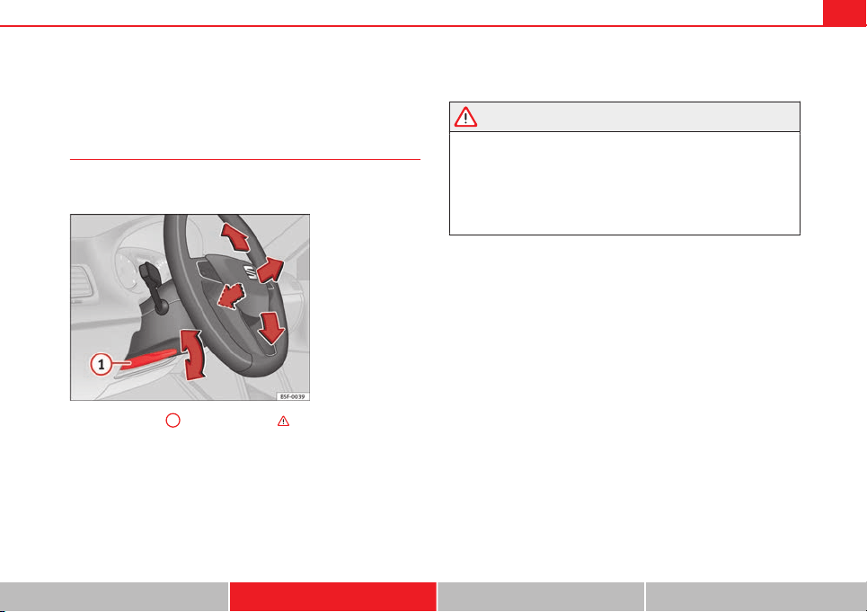
143Driving
Driving
Steering
Adjusting the steering wheel position
The height and reach of the steering wheel can be freely ad-
justed to suit the driver.
Fig. 85 Lever in the low-
er left side of the steer-
ing column
– Press the lever
1
⇒ Fig. 85 down ⇒
– Move the steering wheel to the desired position.
– Move the lever up, applying pressure until the close position is
reached.
WARNING
● Never adjust the position of the steering wheel when the vehicle is
moving, as this could cause an accident.
● Move the lever up firmly so the steering wheel position does not acci-
dentally change during driving. risk of accident!
● Make sure you are capable of reaching and holding the upper part of
the steering wheel, while your back remains well supported by the back-
rest: risk of accident!
Safety First Operating instructions Practical Tips Technical specifications
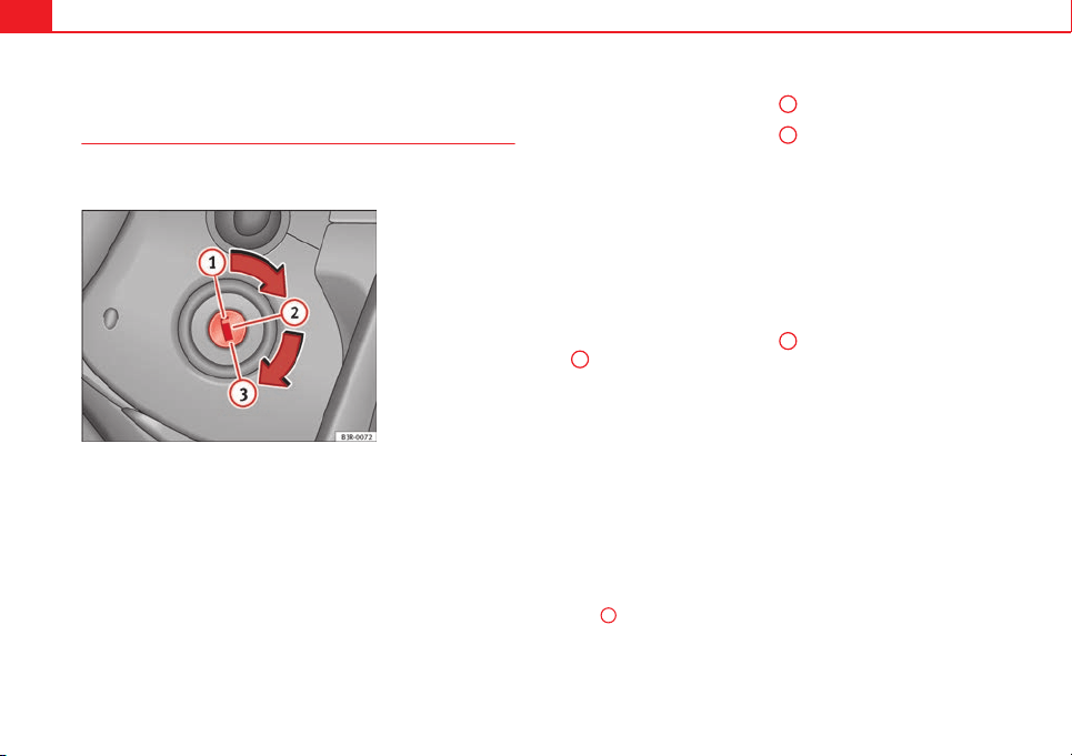
144 Driving
Ignition lock
Starting the engine with the ignition key
Switch on the ignition with the key in the ignition and start
the engine.
Fig. 86 Ignition key po-
sitions
Steering wheel lock
– To lock the steering wheel, remove the key from the ignition and
turn the wheel until it locks. In vehicles with the automatic gear-
box*, the selector lever must be in the position P in order to re-
move the key.
– To unlock the steering wheel, insert the key into the ignition
and simultaneously turn the key (in the direction of the arrow)
and the steering wheel.
Warning: If the steering wheel cannot be turned, this is because
the steering wheel lock is activated.
Switching the ignition on/off, preheating
– Turn the ignition key to position
2
to switch on the ignition.
– Turn the ignition key to position
1
to switch off the ignition.
Preheating is produced in Diesel vehicles when the ignition is
switched on.
Starting up the engine
– Manual gearbox: Press the clutch pedal all the way down and
move the gearbox lever into neutral.
– Automatic gearbox: Press the brake pedal and move the selec-
tor lever to position P or N.
– Turn the ignition key to position
3
. The key returns to position
2
automatically. Do not press the accelerator.
Diesel engines can take a few seconds longer than usual to start
on cold days. Therefore the clutch pedal (manual gearbox) or the
brake pedal (automatic gearbox) must remain pressed until the en-
gine starts up. During preheating, the warning lamp remains lit.
The preheating time depends on the coolant and exterior tempera-
tures. When the engine is at operating temperature or at outside
temperatures above +8 °C (46 °F) the warning lamp will only
light up for about one second. This means that the engine starts
immediately.
If the engine does not immediately start up, interrupt the starting process
and try again after 30 seconds. To start the engine again, return the key to
position
1
.

145Driving
Start-Stop System*
If the vehicle is stopped and the Start-Stop system* switches off the engine,
the ignition remains switched on.
Automatic gearbox: Before leaving the vehicle, make sure that the ignition
is switched off and the selector lever is in position P.
Driver messages on the instrument panel display
Press the clutch
This message appears on vehicles with a manual gearbox if the driver tries
to start the engine without having the clutch pedal pressed. The engine will
only start if you press the clutch pedal.
Press the brake
This message appears on vehicles with an automatic gearbox if the driver
tries to start the engine without having the brake pedal pressed.
Select N or P
This message appears if you try to start or stop the engine when the selec-
tor lever of the automatic gearbox is not in position P or N. The engine can
only start or stop in these positions.
Engage position P; the vehicle can move; doors can only close in position P.
For safety reasons, this driver message appears and an audible warning
sounds if the selector lever of the automatic gearbox is not in position P af-
ter you switch off the ignition. Otherwise the vehicle could move.
Gear change: selector lever in the drive position!
This driver message is displayed and a buzzer is sounded when the selector
lever is not in the position P when the driver door is opened. Put the selec-
tor lever in position P; otherwise the vehicle can roll away.
Ignition is switched on
This driver message is displayed and a buzzer is sounded when the driver
door is opened with the ignition switched on.
WARNING
● Never run the engine in confined spaces, as the exhaust gases are
poisonous.
● Never remove the key from the ignition if the vehicle is in motion.
Otherwise, the steering could suddenly lock, making it impossible to
steer the vehicle: risk of accident!
● Always take the key with you when you leave the vehicle. This is par-
ticularly important if there are children in the vehicle, as they might oth-
erwise be able to start the engine or use power-operated equipment (e.g.
the electric windows), which could cause injuries.
CAUTION
Avoid high engine speeds, full throttle and extreme load conditions until
the engine has reached its normal operating temperature, otherwise this
can damage the engine.
For the sake of the environment
Do not warm up the engine by running it with the car stationary. You should
drive off as soon as you start the engine. This will help avoid unnecessary
exhaust emissions.
Note
● If it is difficult to turn the ignition key to the position
1
, turn the steer-
ing wheel to both sides to release the steering lock.
● When starting from cold, the engine may be a little noisy for the first few
seconds until oil pressure has built up in the hydraulic valve lifters. This is
quite normal, and no cause for concern.
● If the vehicle battery is disconnected and reconnected, the key must re-
main in the position
1
for around 5 seconds before starting up.
● Vehicles with automatic gearbox: After switching off the ignition, you
can only remove the ignition key if the selector lever is in position “P” (park-
ing lock). Next, the selector lever is locked.
Safety First Operating instructions Practical Tips Technical specifications
146 Driving
Switching off the engine with the key
Switching off the engine
– Stop the vehicle.
– Turn the ignition key to position
0
.
Engaging the steering wheel lock
Important: selector lever (automatic gearbox*) must be in position
P.
– Remove the key from the ignition in position
1
⇒ Fig. 86 ⇒ .
– Turn the steering wheel until you hear it engage.
Possible vehicle theft is prevented with the steering lock engaged.
WARNING
● Never switch the engine off until the vehicle is stationary. The brake
servo and power steering functions will not be completely covered under
warranty. More force may also be needed to turn the steering wheel or to
brake. As you cannot steer and brake in the normal manner, there is a
greater risk of accidents and serious injury.
● Never remove the key from the ignition if the vehicle is in motion.
Otherwise, the steering could lock making it impossible to steer the vehi-
cle.
● Always take the ignition key with you whenever you leave the vehicle,
even temporarily. This is particularly important if there are children in
the vehicle, as they might otherwise be able to start the engine or use
power-operated equipment (e.g. the electric windows), which could
cause injuries.
CAUTION
If the engine has been running under high load for a long time, there is a
risk of heat building up in the engine compartment after the engine has
been switched off; this could cause engine damage. For this reason, you
should idle the engine for approx. 2 minutes before you switch it off.
Note
● After the engine is switched off the radiator fan may run on for up to 10
minutes, even if the ignition is switched off. It is also possible that the fan
turns itself on once more if the coolant temperature increases due to the
heat accumulated in the engine compartment or due to its prolonged expo-
sure to solar radiation.
● If the vehicle is stopped and the Start-Stop system* switches off the en-
gine, the ignition remains switched on. Make sure that the ignition is
switched off before leaving the vehicle, otherwise the battery could dis-
charge.
Kick-down
The kick-down feature allows maximum acceleration to be
reached.
If the eco*
⇒
page 172 mode has been selected in SEAT Drive Mode*, and
the accelerator is pressed beyond a hard point, the engine power is auto-
matically controlled to give your vehicle maximum acceleration.
WARNING
Please note that if the road surface is slippery or wet, the kick-down fea-
ture could cause the driving wheels to spin, which could result in skid-
ding.
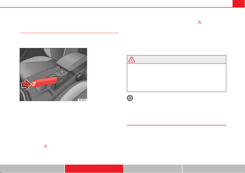
147Driving
Handbrake
Using the handbrake
The handbrake should be applied firmly to prevent the vehi-
cle from accidentally rolling away.
Fig. 87 Handbrake be-
tween the front seats
Always apply the handbrake when you leave your vehicle and when
you park.
Applying the handbrake
– Pull the handbrake lever up firmly ⇒ Fig. 87.
Releasing the handbrake
– Pull the lever up slightly and press the release knob in the di-
rection of the arrow ⇒ Fig. 87 and guide the handbrake lever
down fully ⇒
.
Always apply the handbrake as far as it will go in order to prevent yourself
from driving with the handbrake applied by mistake ⇒
.
The handbrake warning lamp lights up when the handbrake is applied
and the ignition switched on. The warning lamp turns off when the hand-
brake is released.
If you drive faster than 6 km/h (4 mph) with the handbrake on, the following
message* will appear on the instrument panel display: HANDBRAKE ON. You
will also hear an audible warning.
WARNING
● Never use the handbrake to stop the vehicle when it is in motion. The
braking distance is considerably longer, because braking is only applied
to the rear wheels. Risk of accident!
● If the handbrake is only partially released, this will cause the rear
brakes to overheat, which can impair the function of the brake system
and could lead to an accident. This also causes premature wear on the
rear brake pads.
CAUTION
Always apply the handbrake before you leave the vehicle. The first gear
should also be selected.
Parking
The handbrake should always be firmly applied when the
vehicle is parked.
Always note the following points when parking the vehicle:
– Use the brake pedal to stop the vehicle.
Safety First Operating instructions Practical Tips Technical specifications
148 Driving
– Apply the handbrake.
– Select first gear.
– Switch the engine off and remove the key from the ignition. Turn
the steering wheel slightly to engage the steering lock.
– Always take you keys with you when you leave the vehicle ⇒
.
Additional notes on parking the vehicle on gradients:
Turn the steering wheel so that the vehicle rolls against the kerb if it started
to roll.
● If the vehicle is parked facing downhill, turn the front wheels so that
they point towards the kerb.
● If the vehicle is parked facing uphill, turn the front wheels so that they
point away from the kerb.
● Secure the vehicle as normal by applying the handbrake firmly and se-
lecting first gear.
WARNING
● Take measures to reduce the risk of injury when you leave your vehi-
cle unattended.
● Never park where the hot exhaust system could ignite inflammable
materials, such as dry grass, low bushes, spilt fuel etc.
● Never allow vehicle occupants to remain in the vehicle when it is
locked. They would be unable to open the vehicle from the inside, and
could become trapped in the vehicle in an emergency. In the event of an
emergency, locked doors will delay assistance to vehicle occupants.
● Never leave children alone in the vehicle. They could set the vehicle
in motion, for example, by releasing the handbrake or the gearbox lever.
● Depending on weather conditions, it may become extremely hot or
cold inside the vehicle. This can be fatal.
Hill hold assist*
The Hill hold assist facilitates moving off when driving up-
hill.
Important: the driver door must be closed, the seat belt fastened and the
engine running.
The system is activated when you press and hold the brake pedal for a few
seconds.
To prevent the vehicle from rolling backwards when moving off, the brake
force will remain for a moment after releasing the brake pedal. This short
space of time is enough to start the vehicle with ease.
WARNING
● The smart technology included in the Hill hold assist cannot defy the
laws of physics. Do not let the extra convenience afforded by the Hill hold
assist tempt you into taking any risks when driving.
● The Hill hold assist cannot maintain the vehicle stationary on a slope
in all situations (e.g. on slippery or icy ground).
● If you do not start the vehicle immediately after taking your foot off
the brake pedal, the vehicle may start to roll back under certain circum-
stances. Depress the brake pedal or use the handbrake immediately.
● If the engine stalls, depress the brake pedal or use the handbrake im-
mediately.
● If you are moving off on a slope in stop-and-go traffic, press and hold
the brake pedal for a few seconds before driving off. This will prevent the
vehicle from rolling back unintentionally.
Note
The SEAT Official Service or a specialised workshop can tell you if your vehi-
cle is equipped with the Hill hold assist.
149Driving
Speed warning function
Introduction
The speed warning function can help prevent you exceeding
a particular pre-set maximum speed.
The speed warning function will warn the driver if a pre-set maximum speed
is exceeded. The system gives a warning buzzer signal if the set speed is
exceeded by about 3 km/h (2 mph). The warning lamp and the driver
message Speed limit exceeded! will be displayed simultaneously on the in-
strument panel display. The warning lamp switches off when reducing
speed below the stored maximum limit.
You are recommended to store this speed limit warning if you always wish
to be reminded of a particular speed limit. This could be when driving in
countries with general speed limits, or if a particular speed should not be
exceeded when winter tyres are fitted etc.
Note
● Please bear in mind that, even with the speed warning function, it is still
important to keep an eye on the vehicle speed with the speedometer and to
observe the legal speed limits.
● The speed limit warning function in the version for several countries
warns you at a speed of 120 km/h (80 mph). This is a factory-set speed lim-
it.
Setting speed limit warning
You can use the radio or the Easy Connect* to set, alter or
cancel the speed limit warning.
Vehicles with radio
– Select:
SETUP
button > control button Driver assistant > Speed
warning.
Vehicles with Easy Connect
– Select: Systems control button or Vehicle systems > Driver assis-
tant > Speed warning.
The warning limit can be set from 30 to 240 km/h (20 to 150 mph). The ad-
justment is done in 10 km/h (mph) intervals.
Start-Stop system*
Description and operation
The Start-Stop system helps save fuel and reduce CO
2
emissions.
In Start-Stop mode, the engine will automatically switch off when the vehi-
cle stops, when stopping at traffic lights for example. The ignition remains
switched on during the stopping phase. The engine automatically switches
back on when required.
As soon as the ignition is switched on, the Start-Stop function is automati-
cally activated.
Safety First Operating instructions Practical Tips Technical specifications
150 Driving
Basic requirements for the Start-Stop mode
● The driver door must be closed.
● The driver must have their seat belt fastened.
● The bonnet must be closed.
● The vehicle must have travelled at more than 4 km/h (2 mph) since the
last stop.
● The vehicle cannot be towing a trailer.
WARNING
● Never switch the engine off until the vehicle is stationary. The brake
servo and power steering functions will not be completely covered under
warranty. More force may also be needed to turn the steering wheel or to
brake. As you cannot steer and brake in the normal manner, there is a
greater risk of accidents and serious injury.
● Never remove the key from the ignition if the vehicle is in motion.
Otherwise, the steering could lock making it impossible to steer the vehi-
cle.
● Always take the ignition key with you whenever you leave the vehicle,
even temporarily. This is particularly important if there are children in
the vehicle, as they might otherwise be able to start the engine or use
power-operated equipment (e.g. the electric windows), which could
cause injuries.
● To avoid injury, make sure that the Start-Stop system is switched off
when working in the engine compartment ⇒ page 152.
CAUTION
The Start-Stop system must always be switched off when driving through
flooded areas ⇒ page 152.
Stop/Start the engine
Vehicles with a manual gearbox
– When the vehicle is stopped, put it into neutral and release the
clutch pedal. The engine will switch off. The warning lamp
will appear on the instrument panel display.
– When the clutch pedal is pressed the engine will start up again.
The warning lamp will switch off.
Vehicles with an automatic gearbox
– Use the foot brake to bring the vehicle to a stop and keep the
brake pedal pressed down with your foot. The engine will switch
off. The warning lamp will appear in the display.
– When you take your foot off the brake pedal the engine will start
up again. The warning lamp will switch off.
Additional information related to the automatic gearbox
The engine stops when the selector lever is in the positions P, D, N and S, in
addition to when in manual mode. With the selector lever in position P, the
engine will also remain switched off when you take your foot off the brake
pedal. In order to start the engine up again the accelerator must be press-
ed, or another gear engaged or the brake released.
If the selector lever is placed in position R during the stopping phase, the
engine will start up again.
Change from position D to P to prevent the engine from accidentally starting
when changing and passing by position R.
151Driving
Note
● You can control whether the engine should switch off or not by reducing
or increasing the brake force applied. While the vehicle remains stopped,
the engine will not stop if the brake pedal is slightly pressed, in traffic jams
with frequent stopping and starting for example. As soon as strong pressure
is applied to the brake pedal, the engine will stop.
● In vehicles with manual gearbox, during the stopping phases the brake
pedal must remain depressed to prevent the vehicle from moving.
● If the engine stalls in vehicles with manual gearbox, it can be directly
started up again by immediately pressing the clutch pedal.
General notes
The system can interrupt the Start-Stop mode frequently for
different reasons.
The engine does not switch off
Before the stopping phase, the system verifies whether certain conditions
are met. The engine does not switch off, in the following situations for ex-
ample:
● The engine has not yet reached the minimum required temperature for
the Start-Stop mode.
● The interior temperature selected for the air conditioner has not yet
been reached.
● The interior temperature is very high/low.
● Defrost function button activated ⇒ page 135.
● The parking aid* is switched on.
● The battery is very low.
● The steering wheel is overly turned or is being turned.
● If there is a danger of misting.
● After engaging reverse gear.
● In case of a very steep gradient.
The indication is shown on the instrument panel display, and in addition,
the driver information system* shows, .
The engine starts by itself
During a stopping phase the normal Start-Stop mode can be interrupted in
the following situations: The engine restarts by itself without involvement
from the driver.
● The interior temperature differs from the value selected on the air condi-
tioner.
● Defrost function button activated ⇒ page 135.
● The brake has been pressed several times consecutively.
● The battery is too low.
● High power consumption.
Note
In vehicles with an automatic gearbox, if the selector lever is placed in posi-
tion D, N or S after engaging reverse gear, the vehicle must be driven at a
speed faster than 10 km/h (5 mph) for the system to return to conditions in
which the engine can be stopped.
Safety First Operating instructions Practical Tips Technical specifications
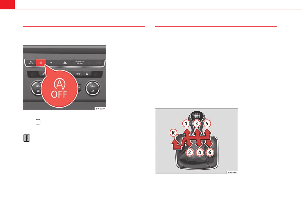
152 Driving
Manually switching on/off the Start-Stop system
If you do not wish to use the system, you can switch it off
manually.
Fig. 88 Centre console:
Start-Stop system button
– To manually switch on/off the Start-Stop system, press the but-
ton
. The button symbol remains lit up yellow when the sys-
tem is switched off.
Note
The system is automatically switched on each time the engine is deliberate-
ly stopped during a stopping phase. The engine will start automatically.
Driver messages on the instrument panel display
Start-Stop system deactivated. Start the engine manually
This driver message is displayed when certain conditions are not met during
the stopping phase and the Start-Stop system cannot restart the engine.
The engine must be started manually.
Start-Stop system: Fault! Function not available
There is a fault in the Start-Stop system. Take the vehicle to a workshop to
have the fault repaired.
Manual gearbox
Changing gears
Fig. 89 Gear shift pat-
tern of a 5 or 6-speed
manual gearbox
The position of each of the gears is shown on the gear stick
⇒
Fig. 89.
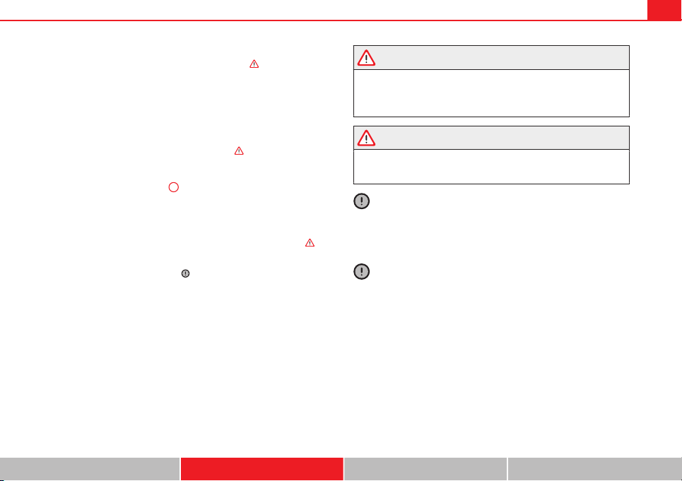
153Driving
● Press and hold the clutch pedal to the floor.
● Place the gearbox lever in the required position ⇒
.
● Release the clutch pedal to engage clutch.
In some countries the clutch pedal must be fully pressed down for the en-
gine to start.
Selecting reverse gear
● Engage reverse gear only when the vehicle is stopped.
● Press and hold the clutch pedal to the floor ⇒
.
● Move the gearbox lever into the neutral position and press it down.
● Move the gearbox lever completely to the left and then forwards to posi-
tion it in reverse gear ⇒ Fig. 89
R
.
● Release the clutch pedal to engage clutch.
Changing down gears
While driving, changing down a gear must always be done gradually, i.e. to
the gear directly below and when the engine speed is not too high ⇒
.
Changing down while bypassing one or various gears at high speeds or at
high engine speeds can damage the clutch and the gearbox, even if the
clutch pedal remains depressed ⇒
.
Kick-down
In vehicles with a speed limiter, the kick-down function enables the pro-
grammed speed to be exceeded deliberately, i.e. when overtaking.
When the accelerator is pressed to the floor, the speed limiter is temporarily
deactivated as the programmed speed is exceeded.
When the speed of the vehicle falls below the programmed value again, and
when the accelerator is not pressed to the floor, the speed limiter is reacti-
vated.
WARNING
When the engine is running, the vehicle will start to move as soon as a
gear is engaged and the clutch released. This is also the case with the
electro-mechanical parking brake switched on.
● Never engage reverse gear when the vehicle is moving.
WARNING
If the gear is changed down inappropriately by selecting a gear that is
too low, you may lose control of the vehicle, causing an accident and se-
rious injuries.
CAUTION
When travelling at high speeds or at high engine speeds, selecting a gear
that is too low can cause considerable damage to the clutch and the gear-
box. This can also occur if the clutch pedal is pressed and held and it does
not engage.
CAUTION
To prevent damage and avoid premature wear, please observe the follow-
ing:
● Do not rest your hand on the gear lever while driving. The pressure ap-
plied by your hand is transmitted to the gearbox selector forks.
● Always ensure that the vehicle is completely stopped before engaging
the reverse gear.
● Always press the clutch to the floor when changing gears.
● Never hold the vehicle “on the clutch” on hills with the engine on.
Safety First Operating instructions Practical Tips Technical specifications
154 Driving
Automatic gearbox/DSG automatic gearbox*
Introduction
Your vehicle is equipped with an electronically controlled manual gearbox.
Torque between the engine and the gearbox is transmitted via two inde-
pendent clutches. They replace the torque converter found on conventional
automatic gearboxes and allow for smooth, uninterrupted acceleration of
the vehicle.
The tiptronic system allows the driver to change gears manually if desired
⇒ page 159, Changing gears in tiptronic mode*.
Selector lever positions
The selector lever position engaged is highlighted on the display in the in-
strument cluster. With the selector lever in the manual gearbox positions G,
D, E and S, the engaged gear is also indicated on the display.
P – Parking lock
When the selector lever is in this position, the driven wheels are locked me-
chanically. The parking lock must be engaged only when the vehicle is sta-
tionary ⇒
.
The interlock button (the button on the selector lever handle) must be
pressed in and simultaneously the brake pedal must be depressed before
moving the selector lever either in or out of position P.
R – Reverse gear
Reverse gear must be engaged only when the vehicle is stationary and the
engine is idling ⇒
.
To move the selector lever to position R, the interlock button must be press-
ed in and at the same time the brake pedal must be depressed. The reverse
lights come on when the selector lever is in the R position with the ignition
on.
N – Neutral (idling)
With the selector lever in this position, the gear is in neutral.
D/S – Permanent drive (forward) position
The selector lever in the D/S position enables the gears to be controlled in
normal mode (D) or Sport (S). To select Sport mode (S), move the selector
lever backwards. Moving the lever again will select normal mode (D). The
selected driving mode is shown on the instrument panel display.
In normal mode (D), the gearbox automatically selects the best gear ratio.
This depends on the engine load, the road speed and the dynamic gear
control programme (DCP).
Sport mode (S) must be selected for a sporty driving style. This setting
makes use of the engine's maximum power output. When accelerating the
gear shifts will be noticeable.
The brake pedal must be pressed when moving the selector lever from D/S
to N if the vehicle is stationary or at speeds below 5 km/h (3 mph) ⇒
.
Under certain circumstances (e.g. when driving in mountains) it can be ad-
vantageous to switch temporarily to tiptronic mode ⇒ page 159, in order to
manually select gear ratios to suit the driving conditions.
WARNING
● Take care not to accidentally press the accelerator pedal when the ve-
hicle is stopped. The vehicle could otherwise start moving immediately
(in some cases even if the parking brake is engaged) resulting in the risk
of an accident.
● Never move the selector lever to R or P when driving. Failure to do so
could result in an accident.
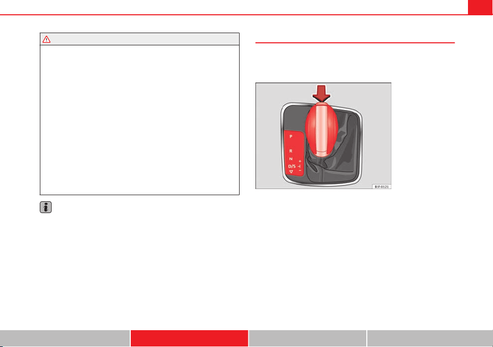
155Driving
WARNING (Continued)
● With selector lever in any position (except P) the vehicle must always
be held with the foot brake when the engine is running. This is because
an automatic gearbox still transmits power even at idling speed, and the
vehicle tends to “creep”. The accelerator pedal must on no account be
pressed inadvertently when a gear is engaged with the vehicle station-
ary. The vehicle could otherwise start moving immediately (in some ca-
ses even if the parking brake is engaged) resulting in the risk of an acci-
dent.
● While you are selecting a gear and the vehicle is stopped with the en-
gine running, do not accelerate. Failure to do so could result in an acci-
dent.
● As a driver you should never leave your vehicle if the engine is run-
ning and a gear is engaged. If you have to leave your vehicle while the
engine is running, you must apply the handbrake and engage the parking
lock P.
● To avoid accidents, apply the handbrake and put the selector lever in
position P before opening the bonnet and working on the vehicle with
the engine running. Please always observe the important safety warn-
ings ⇒ page 209, Working on components in the engine compartment.
Note
● If the selector lever is moved accidentally to N when driving, release the
accelerator and let the engine speed drop to idling before selecting gear
range D or S again.
● Should the power supply to the selector lever be interrupted in posi-
tion P, the selector lever will be locked. If this should happen the manual
release can be used ⇒ page 163.
Selector lever lock
The selector lever lock prevents gears from being engaged
inadvertently, so that the vehicle is not set in motion unin-
tentionally.
Fig. 90 Selector lever
lock
The selector lever lock is released as follows:
– Switch the ignition on.
– Press the brake pedal and at the same time press in the inter-
lock button.
Automatic selector lever lock
With the ignition switched on, the selector lever is locked in the positions P
and N. The brake pedal must be pressed to release the lever while pressing
the release button if the selector lever is in the position P. As a reminder for
the driver, with the lever in positions P or N the following message will be
shown on the display:
When stationary, apply footbrake while selecting a gear.
Safety First Operating instructions Practical Tips Technical specifications

156 Driving
The selector lever lock only works if the vehicle is stationary or driving at
speeds up to 5 km/h (3 mph). At higher speeds the selector lever lock in
the N position is disengaged automatically.
The selector lever lock is not engaged if the selector lever is moved quickly
through position N (e.g. when shifting from R to D). This makes it possible,
for instance, to rock the vehicle backwards and forwards if it is stuck. The
selector lever lock engages automatically if the brake pedal is not de-
pressed and the lever is in position N for more than about two seconds.
Interlock button
The interlock button on the selector lever handle prevents the driver from
inadvertently engaging certain gears. Press the button in to disengage the
selector lever lock. The selector lever positions in which the interlock button
has to be pressed are shown in the illustration, highlighted in colour
⇒ Fig. 90.
Safety interlock for ignition key
Once the ignition has been turned off, the key may be removed only if the
gear selector is in position P. While the key is not in the ignition, the selec-
tor lever is locked in position P.
Note
● If the selector lever lock does not engage, there is a fault. The transmis-
sion is interrupted to prevent the vehicle from accidentally moving. Follow
the procedure below in order for the selector lever lock to engage again:
● >With a 6-speed gearbox: press the brake pedal and release it again.
● >With a 7-speed gearbox: press the brake pedal. Move the selector lever
to position P or N and subsequently engage a gear.
● Despite a gear being engaged, the vehicle does not move forwards or
back. Proceed to the next mode:
● When the vehicle does not move in the required direction, the system
may not have the gear range correctly engaged. Press the brake pedal and
engage the gear range again.
● If the vehicle still does not move in the required direction, there is a sys-
tem malfunction. Seek specialist assistance and have the system checked.
Driving tips
The gearbox changes gear ratios automatically as the vehi-
cle moves.
The engine can only start with the selector lever in the position P or
N. At low temperatures, below -10 °C (50 °F), the engine can only
start with the selector lever in the position P.
Starting the vehicle
– Press and hold the brake pedal.
– Press and hold the interlock button (the button in the selector
lever handle), move the selector lever to the desired position,
for instance D ⇒ page 154, and release the interlock button.
– Wait for the gearbox to engage the gear (a slight movement can
be felt).
– Release the brake and press the accelerator ⇒
.
Stopping briefly
– Apply the foot brake to hold the vehicle when stationary (for in-
stance at traffic lights). Do not press the accelerator.

157Driving
Stopping/Parking
If the driver door is opened and the selector lever is not in position
P, the vehicle could move. Driver message: Gear change: selector
lever in drive position! will be displayed. Additionally, a buzzer will
sound.
– Press and hold the brake pedal ⇒
.
– Apply the handbrake.
– Move the selector lever to position P.
Holding the car on a hill
– Always apply the brake pedal firmly to prevent the vehicle from
“moving backwards; if necessary, apply the handbrake” ⇒
.
Do not try to stop the vehicle “rolling back” by increasing the
engine speed when a gear is engaged (pressing the accelera-
tor) ⇒
.
Moving off uphill in vehicles without Hill start assistant*
– Apply the handbrake.
– Once you have engaged a gear press the accelerator carefully
and disengage the handbrake.
Moving off uphill in vehicles without Hill start assistant*
– Once you have engaged a gear, release the footbrake and press
the accelerator ⇒ page 148, Hill hold assist*.
Driving down hills: In some situations (on mountain roads or when towing a
trailer or caravan) it can be advantageous to switch temporarily to the man-
ual gearbox programme so that the gear ratios can be selected manually to
suit the driving conditions ⇒
.
On level ground it is sufficient to move the selector lever to position P. On
slopes, first engage the parking brake and then put the selection lever into
the P position. This avoids overloading the locking mechanism and it will be
easier to move the selector lever from position P.
WARNING
● As a driver you should never leave your vehicle if the engine is run-
ning and a gear is engaged. If you have to leave your vehicle while the
engine is running, you must apply the handbrake and engage the parking
lock P.
● If the engine is running and a gear is engaged (D/S or R) or the vehi-
cle is in tiptronic mode, you will need to hold the car with the footbrake.
Otherwise, the car will creep forwards as the power transmission is not
fully interrupted even when the engine is idling.
● Take care not to accidentally press the accelerator pedal when the ve-
hicle is stopped. The vehicle could otherwise start moving immediately
(in some cases even if the parking brake is engaged) resulting in the risk
of an accident.
● While you are selecting a gear and the vehicle is stopped with the en-
gine running, do not accelerate. Failure to do so could result in an acci-
dent.
● Never move the selector lever to R or P when driving: this could result
in an accident!
● Before you drive down a steep gradient, reduce your speed and use
tiptronic to select a low gear.
● Never allow the brake to rub and do not use the brake pedal too often
or for long periods. Constant braking causes overheating in the brakes.
This could significantly reduce braking power, increase braking distance
or even result in the total failure of the brake system.
● To avoid rolling back on gradients always hold the vehicle with the
footbrake or handbrake if you have to stop.
Safety First Operating instructions Practical Tips Technical specifications
158 Driving
CAUTION
● If you stop the vehicle on a gradient, do not attempt to stop it from roll-
ing by depressing the accelerator when a gear has been selected. This
could cause overheating and damage the automatic gearbox. Apply the
handbrake firmly or press the brake pedal in order to prevent the vehicle
from rolling back.
● If you allow the car to roll with the selector lever in position N with the
engine switched off, the automatic gearbox will be damaged as it will not be
lubricated.
● In certain driving situations or traffic conditions, such as frequently
starting, prolonged creeping of the vehicle, or traffic jams with continuous
stoppages, the automatic gearbox could overheat causing damage! If the
warning lamp lights up, stop the vehicle as soon as possible and wait for
the gearbox to cool ⇒ page 162.
Downhill speed control*
The downhill speed control function helps the driver when
driving down steep gradients.
Downhill speed control is activated when the selector lever is in D/S and
the driver applies the foot brake. The automatic gearbox automatically en-
gages a lower gear that is suitable for the slope. The downhill speed control
function attempts to maintain the speed at which the vehicle was travelling
when the foot brake was applied (subject to the laws of physics and techni-
cal drive limitations). It may be necessary to adjust the speed again using
the foot brake in certain situations. Given that the downhill speed control
can only change down to 3rd gear, on very steep descents the tiptronic
mode may be required. In this case, manually reduce the tiptronic to 2nd or
1st gear to use the engine brake and reduce the charge on the brakes.
Downhill speed control is deactivated as soon as the road levels out again
or you press the accelerator pedal.
On vehicles with cruise control system* ⇒ page 164, downhill speed con-
trol is activated when you set a cruising speed.
WARNING
The downhill speed control cannot defy the laws of physics. Therefore,
speed cannot be maintained constant in all situations. Always be pre-
pared to use the brakes!
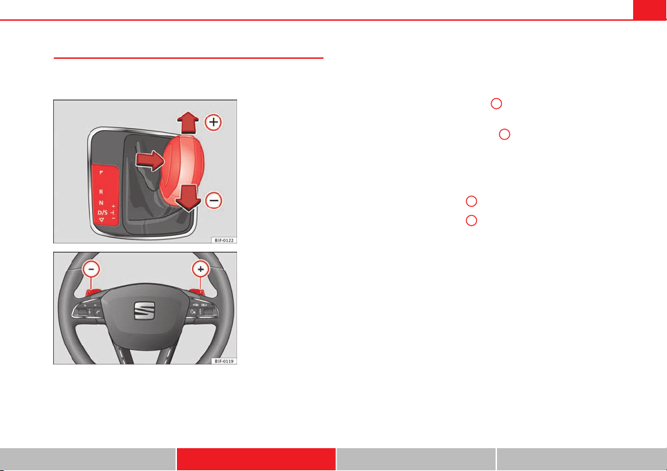
159Driving
Changing gears in tiptronic mode*
The tiptronic gives the driver the option to change gears
manually.
Fig. 91 Centre console:
changing gear with Tip-
tronic
Fig. 92 Steering wheel:
automatic gearbox levers
Changing gear manually with the selector lever
It is possible to change to tiptronic mode, both when the vehicle is
stopped and while driving.
– To switch to tiptronic mode, move the selector lever from posi-
tion D/S to the right. As soon as the change is made, the selec-
tor lever will be shown in the position G (i.e. G4 means that 4th
gear is engaged) on the instrument panel display.
– Move the selector lever forwards
+
to select a higher gear
⇒ Fig. 91.
– Move the selector lever backwards
-
to select a lower gear.
Changing gear manually with the gearshift paddles*
The gearshift paddles can be used when the selector lever is in the
position D/S or G.
– Press the gearshift paddle
+
to select a higher gear ⇒ Fig. 92.
– Press the gearshift paddle
-
to select a lower gear.
– With the selector lever in position D/S, if no paddle is operated
during a short period of time, the gearbox control system
switches back to automatic mode. To switch to permanent man-
ual gear change using the gearshift paddles, move the selector
lever from position D/S to the right.
When accelerating, the gearbox automatically shifts up into the next gear
shortly before the maximum engine speed is reached.
If you select a lower gear, the automatic gearbox will not shift down until
there is no risk of overrevving the engine.
When the kick-down feature is used, the gearbox shifts down to a lower
gear, depending on road speed and engine speed.
Safety First Operating instructions Practical Tips Technical specifications
160 Driving
Kick-down feature
The kick-down feature allows maximum acceleration to be
reached.
When the accelerator pedal is pressed right down past the point of resist-
ance at full throttle, the gearbox will shift down to a lower gear, depending
on road speed and engine speed. The upshift to the next higher gear is de-
layed until the engine reaches maximum rpm.
WARNING
Please note that if the road surface is slippery or wet, the kick-down fea-
ture could cause the driving wheels to spin, which could result in skid-
ding.
Launch Control Programme
1)
The Launch control programme enables maximum accelera-
tion.
Important: the engine must have reached operating temperature
and the steering wheel must not be turned.
The engine speed for Launch control is different on petrol and die-
sel engines. Before you can use the Launch control, you must first
switch off the traction control system (ASR), either using the Easy
Connect system ⇒ page 79, or with the switch
OFF
; the warning
lamp will stay on or will flash slowly depending on whether the
vehicle has a driver information system*
2)
.
– When the engine is running, switch off the traction control
(ASR)
2)
3)
.
– Move the selector lever to position “S” or tiptronic, or select the
driving mode Sport from the SEAT Drive Mode* ⇒ page 171.
– Press the brake pedal firmly with your left foot and hold it down
for at least one second.
– With your right foot, press the accelerator down to the full throt-
tle or kick-down position. The engine speed will stabilise at ap-
prox. 3200 rpm (petrol engine) or approx. 2000 rpm (diesel en-
gine).
– Take your left foot off the brake pedal.
1)
Valid for vehicles: with Launch Control/6-Speed DSG with diesel engines superior to 125
kW and petrol engines superior to 140 kW.
2)
On vehicles with the driver information system, the ESP lamp lights up permanently and
the corresponding text message Stability control deactivated (temporary) appears on the in-
strument panel to indicate the deactivation status.
3)
Vehicles without driver information system: the warning lamp flashes slowly/Vehicles with
driver information system: the warning lamp stays on.
161Driving
WARNING
● Always adapt your driving style to the traffic conditions.
● Only use the Launch control programme when road and traffic condi-
tions permit, and make sure your manner of driving and accelerating the
vehicle does not inconvenience or endanger other road users.
● Make sure that the ESC remains switched on. Please note that when
the ASR and ESC are deactivated, the wheels may start to spin, causing
the vehicle to lose grip. Risk of accident!
● After engaging gear, the Sport mode of the ESC should be deactivated
again by briefly pressing the
OFF
button.
Note
● After using the Launch control programme, the temperature in the gear-
box may have increased considerably. In this case, the programme could be
disabled for several minutes. The programme can be used again after the
cooling phase.
● Accelerating with the Launch control programme places a heavy load on
all parts of the vehicle. This can result in increased wear and tear.
Inertia mode
The inertia mode enables the kinetic energy of the vehicle to be
harnessed enabling certain stretches to be driven without using
the accelerator. This enables fuel to be saved. Use the inertia mode
to let the vehicle roll in advance of, for example, arriving in a town.
Switching on inertia mode
Important: selector lever must be in position D, gradients below
12 %.
– Select Eco mode ⇒ page 171 once in SEAT Drive Mode*.
– Take your foot off the accelerator.
The driver message Inertia will be displayed. At speeds higher
than 20 km/h (12 mph), the gearbox will automatically disengage
and the vehicle will roll freely, without the effect of the engine
brake. While the vehicle rolls, the engine runs at idling speed.
Stopping inertia mode
– Press the brake or the accelerator pedal.
To make use of the braking force and switch off the engine again,
simply press the brake pedal briefly.
Applying both the inertia mode (= prolonged section with less energy) and
the switching off using inertia (= shorter section without the need for fuel)
facilitates improved fuel consumption and emission balance.
WARNING
● If the inertia mode has been switched on, take into account, when ap-
proaching an obstacle and releasing the accelerator pedal, that the vehi-
cle will not decelerate in the usual manner: risk of accident!
● When using inertia mode while travelling down hills, the vehicle can
increase speed: risk of accident!
● If other users drive your vehicle, warn them about inertia mode.
Safety First Operating instructions Practical Tips Technical specifications

162 Driving
Note
● Inertia mode is only available in eco driving mode (SEAT Drive Mode*).
● The driver message Inertia is only displayed with the current consump-
tion. In inertia mode the gear will no longer be displayed (for example: E will
appear in place of E7).
● On downhill sections with gradients above 15 %, the inertia mode will
automatically be switched off temporarily.
Backup programme
A backup programme is in place if a fault should occur in the
control system.
If all the positions of the selector lever are shown over a light background
on the instrument panel display, there is a system fault and the automatic
gearbox will operate in with the backup programme. When the backup pro-
gramme is activated, it is possible to drive the vehicle, however, at low
speeds and within a selected range of gears. In some cases driving in re-
verse gear may not be possible.
CAUTION
If the gearbox operates with the backup programme, take the vehicle to a
specialised workshop and have the fault repaired without delay.
Clutch
Clutch overheated! Stop the vehicle!
The clutch has overheated and could be damaged. In order to prevent the
temperature from increasing again and so that the clutch is cooled, stop the
vehicle and wait for the gearbox to cool down with the selector lever in posi-
tion P and the engine running at idling speed. If the warning does not
switch off, do not continue driving. Seek specialist assistance. Failure to do
so could cause considerable damage to the gearbox. When the warning
switches off, the fault should be corrected by a specialised workshop with-
out delay.
Faults in the gearbox
Gearbox: Fault! Stop the vehicle and place the lever in the position P.
There is a fault in the gearbox. Stop the vehicle in a safe place and do not
continue driving. Seek specialist assistance.
Overheated clutch! Stop the vehicle!
The clutch has overheated and could be damaged. Stop the vehicle and
wait for the gearbox to cool with the engine at idling speed and the selector
lever in position P. When the warning lamp and the driver message switch
off, have the fault corrected by a specialised workshop without delay. If the
warning lamp and the driver message do not switch off, do not continue
driving. Seek specialist assistance.
Gearbox: System fault! You may continue driving.
Have the fault corrected by a specialised workshop without delay.
Gearbox: System fault! You can continue driving with restrictions. Re-
verse gear disabled.
Take the vehicle to a specialised workshop and have the fault repaired with-
out delay.
Gearbox: System fault! You can continue driving in D until switching off
the engine
Stop the vehicle in a safe place well away from moving traffic. Seek special-
ist assistance.
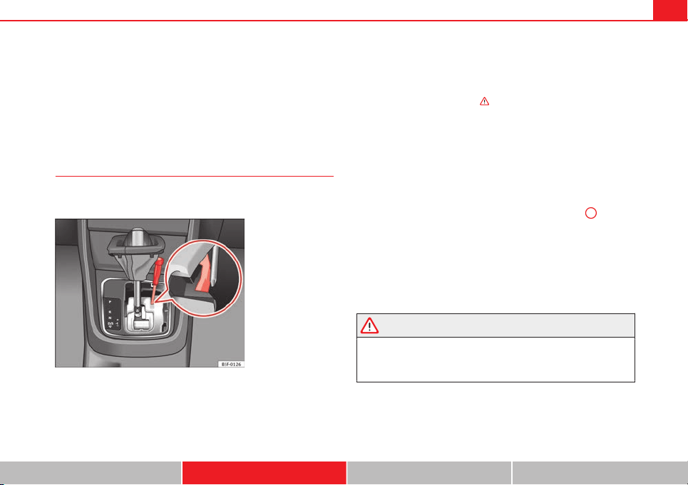
163Driving
Gearbox: too hot. Adapt your driving accordingly
Continue driving at moderate speeds. When the warning lamp switches off,
you can continue driving in a normal manner.
Gearbox: press the brake and engage a gear again.
If the fault was caused by a gearbox with a high temperature, this driver
message will be displayed when the gearbox has cooled again.
Manual release of the selector lever
The selector lever can be released manually if the electrical
power supply should fail.
Fig. 93 Selector lever:
manual release from po-
sition P
The manual release mechanism is located under the selector lever
console on the right side. Releasing the selector lever requires a
certain degree of practical skill. We therefore advise you to obtain
professional assistance.
A screwdriver will be needed to carry out the manual release. Use
the flat part of the screwdriver blade ⇒ page 232.
Removing the cover from the selector lever
– Apply the handbrake ⇒
to ensure that the car does not
move.
– Carefully pull the corners of the selector lever boot and fold up
the selector lever boot (inside out) by hand.
Releasing the selector lever
– Using a screwdriver, press and hold the yellow unlocking tab
sideways ⇒ Fig. 93.
– Now press the interlock button on the selector lever
A
and
move the selector lever to position N.
– After carrying out the manual release, attach the selector lever
boot on the gearbox console again.
If the power supply should ever fail (discharged battery, etc.) and the vehi-
cle has to be pushed or towed, the selector lever must first be moved to po-
sition N. This is possible after operating the manual release mechanism.
WARNING
The selector lever may be moved out of position P only when the hand-
brake is firmly applied. If this does not work, secure the vehicle with the
brake pedal. On a slope the vehicle could otherwise start to move inad-
vertently after shifting the selector lever out of position P - accident risk!
Safety First Operating instructions Practical Tips Technical specifications
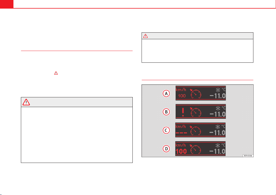
164 Driver assistance systems
Driver assistance systems
Cruise control system (CCS)*
Introduction
The cruise control system (CCS) is able to maintain the set speed from 20
km/h (15 mph).
A constant speed is maintained using the engine power control or by apply-
ing the active brake ⇒
.
Additional information and warnings:
● Change gear ⇒ page 154.
● Accessories and technical modifications ⇒ page 230.
WARNING
Use of the cruise control could cause accidents and severe injuries if it is
not possible to drive at a constant speed maintaining the safety distance.
● Do not use the cruise control in heavy traffic, if the distance from the
vehicle in front is insufficient, on steep roads, with several bends or in
slippery circumstances (snow, ice, rain or loose gravel), or on flooded
roads.
● Never use the CCS when driving off-road or on unpaved roads.
● Always adapt your speed and the distance to the vehicles ahead in
line with visibility, weather conditions, the condition of the road and the
traffic situation.
● To avoid unexpected operation of the cruise control system, turn it off
every time you finish using it.
WARNING (Continued)
● It is dangerous to use a set speed which is too high for the prevailing
road, traffic or weather conditions.
● When travelling down hills, the CCS cannot maintain a constant
speed. The vehicle tends to accelerate under its own weight. Select a
lower gear or use the foot brake to slow the vehicle.
Warning and control lamp
Fig. 94 Instrument panel display: CCS status indications
165Driver assistance systems
Control lamp
lights up Possible cause
Cruise control is active
Several warning and control lamps should light up for a few seconds when
the ignition is switched on, signalling that the function is being verified.
They will switch off after a few seconds.
Displayed on the CCS screen
Status Fig. 94:
CCS temporarily switched off. The set speed is displayed in small fig-
ures.
System error. Contact a specialised workshop.
CCS switched on. The speed memory is empty.
The CCS is switched on. The set speed is displayed in large figures.
WARNING
If the warning lamps and messages are ignored, the vehicle may stall in
traffic, or may cause accidents and severe injuries.
● Never ignore the warning lamps or text messages.
CAUTION
Failure to heed the control lamps and text messages when they appear may
result in faults in the vehicle.
A
B
C
D
Safety First Operating instructions Practical Tips Technical specifications
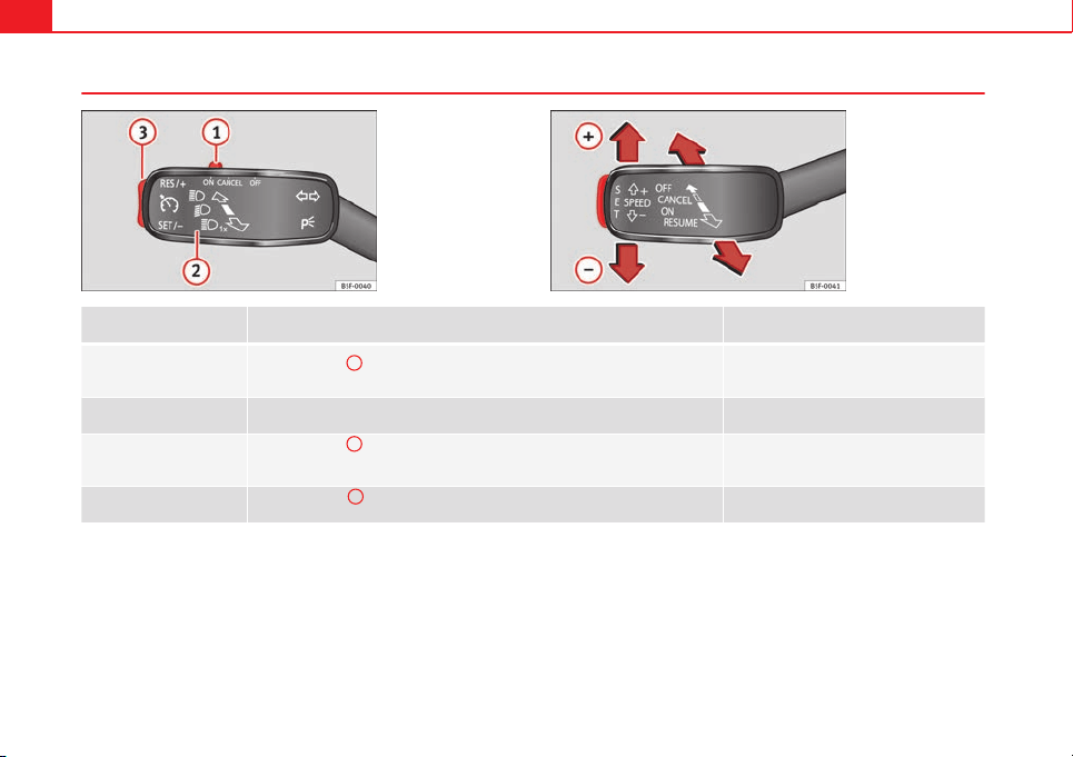
166 Driver assistance systems
Operating the cruise control system*
Fig. 95 On the left of the
steering column:
switches and controls for
operating the CCS
Fig. 96 On the left of the
steering column: Third 6-
position lever for operat-
ing the CCS
Function
Position of the switch, operating the switch on the turn signal lever ⇒ Fig. 95, or
by using the third lever ⇒ Fig. 96
Action
Switching on the CCS
Move the switch
1
on the turn signal lever to the ON position, or move the third
lever to the ON position.
The system is switched on. The system does
not maintain the speed because there is still
no speed set.
Activating the CCS
Press the SET button on the turn signal lever or press the SET button on the third
lever.
The current speed is stored and maintained.
Temporarily switching off
the CCS
Move the switch
1
on the turn signal lever to the CANCEL position. Move the
third lever to the CANCEL position and release it.
OR: Apply the foot brake.
The cruise control system is switched off
temporarily. The speed setting will remain
stored.
Switching on the CCS again
Press the button
3
on the turn signal lever to the RES/+ position, or move the
third lever to the RESUME position and release it.
The stored speed will be saved and will reg-
ulate again.
167Driver assistance systems
Function
Position of the switch, operating the switch on the turn signal lever ⇒ Fig. 95, or
by using the third lever ⇒ Fig. 96
Action
Increasing the stored
speed (during CCS setting)
Depending on equipment fitted:
– briefly press the button
3
on the turn signal lever in the RES
zone– or briefly move the third lever to the RESUME position to increase speed by
1 km/h (1 mph)
– or move the third lever upwards with SPEED+ to increase the speed by 10 km/h
(10 mph) and store it
– or continuously press the button
3
on the turn signal lever in the RES
zone– or move the third lever upwards with SPEED+ continuously
– or move the third lever to the RESUME position and hold it to continuously in-
crease the speed and store it.
The vehicle accelerates actively until it rea-
ches the new stored speed.
Increasing the stored
speed
When the CCS is in the ON position, but DEACTIVATED, the speed setting can be
increased with SPEED+ by 10 km/h (10 mph).
The vehicle accelerates actively until it rea-
ches the new stored speed.
Reducing the stored speed
(during CCS setting)
Depending on equipment fitted:
– briefly press the button
3
on the turn signal lever in the SET zone to reduce
speed by 1km/h (1mph)
– or briefly move the third lever to the SET position to reduce the speed by 1 km/h
(1 mph)
– or move the third lever downwards with SPEED– to reduce the speed by 10 km/
h (10 mph) and store it
– or continuously press the button
3
on the turn signals lever in the SET
zone– or press and hold the button SET on the third lever to reduce speed contin-
uously
– or move the third lever downwards (SPEED–) continuously and store it.
Speed is reduced without braking, by inter-
rupting the accelerator until reaching the
new stored speed.
Setting a lower speed
When the CCS is in the ON position, but DEACTIVATED, the speed setting can be
reduced with SPEED– by 10 km/h (10 mph).
The system is switched off. The stored speed
is deleted.
Switching off the CCS
Move the switch
1
to the OFF position.
OR: move the third lever to the OFF position.
Speed is reduced without intervening in the
braking system, by interrupting the accelera-
tor until reaching the new stored speed.
The value indicated in the table in brackets (in mph, miles per hour) only
refers to instrument panels with indications in miles.
Changing gear in CCS mode
The CCS decelerates as soon as the clutch pedal is pressed, intervening
again automatically after a gear is engaged.
Safety First Operating instructions Practical Tips Technical specifications
168 Driver assistance systems
Travelling down hills with the CCS
When travelling down hills the CCS cannot maintain a constant speed. Slow
the vehicle down using the brake pedal and reduce gears if required.
Automatic off
The cruise control system (CCS) is switched off automatically or temporarily:
● If the system detects a fault that could affect the working order of the
CCS.
● If you press and maintain the accelerator pedal for a certain time, driv-
ing faster than the stored speed.
● If the dynamic driving control systems intervene (i.e. ASR or ESC).
● If the airbag is triggered.
Lane Assist system*
Introduction
Additional information and warnings:
● SEAT information system ⇒ page 73
● Accessories, parts replacement, repairs and modifications ⇒ page 230
WARNING
The intelligent technology in the Lane Assist system cannot change the
limits imposed by the laws of physics and by the very nature of the sys-
tem. Careless or uncontrolled use of the Lane Assist system may cause
accidents and injury. The system is not a replacement for driver aware-
ness.
● Always adapt your speed and the distance to the vehicles ahead in
line with visibility, weather conditions, the condition of the road and the
traffic situation.
● Always keep your hands on the steering wheel so it can be turned at
any time.
● The Lane Assist system does not detect all road markings. The road
surfaces, road structures or objects in poor condition can be incorrectly
detected as road markings under certain circumstances by the Lane As-
sist system. In such situations, switch the Lane Assist system off imme-
diately.
● Please observe the indications on the instrument panel and act as is
necessary.
● Always pay attention to the vehicle's surroundings.
● When the area of vision of the camera becomes dirty, covered or is
damaged, the Lane Assist system function can be affected.
CAUTION
In order to avoid influencing the operation of the system, the following
points must be taken into account:
● Regularly clean the area of vision of the camera and keep it in a clean
state, without snow or ice.
● Do not cover the area of vision of the camera.
● Check that the area of vision of the windscreen camera is not damaged.
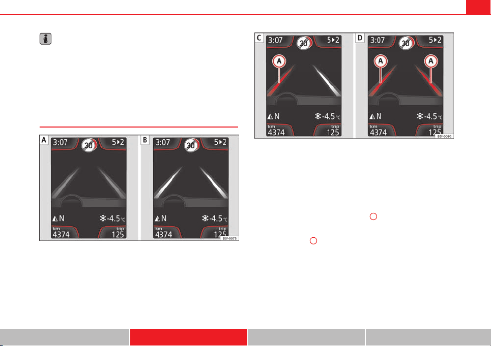
169Driver assistance systems
Note
● The Lane Assist system has been exclusively developed for driving on
paved roads only.
● If the Lane Assist system does not work as described in this chapter, do
not use it and contact a specialised workshop.
● If there is a fault in the system, have it checked by a specialised work-
shop.
Indication on the display and warning lamps
Fig. 97 On the instrument panel display: Indication on the Lane Assist system display
(example 1)
Fig. 98 On the instrument panel display: Indication on the Lane Assist system display
(example 2)
Indications on the display
The system is active, but not available, either because the minimum
speed has not been reached or because the lane lines are not recog-
nised ⇒ Fig. 97 .
The system is active and available, both lane lines are recognised. The
steering angle is not being corrected at this moment ⇒ Fig. 97 .
The system is operational, a yellow line
A
indicates that there was a
risk of involuntarily crossing the lane line and that the steering is being
adjusted to correct the angle ⇒ Fig. 98 .
Two yellow lines
A
light up simultaneously when both lane lines are
recognised and the Lane Assist function is active ⇒ Fig. 98 .
–
–
–
–
Safety First Operating instructions Practical Tips Technical specifications
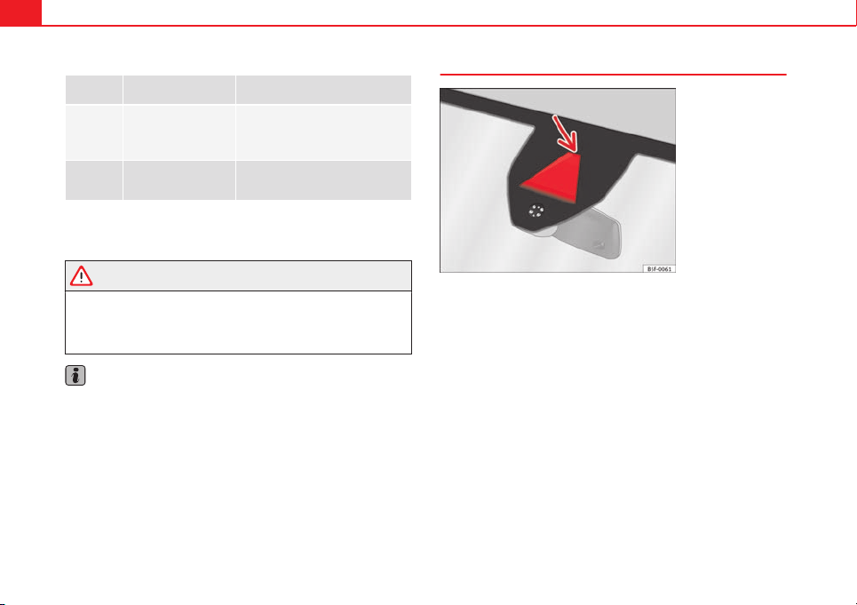
170 Driver assistance systems
Control lamps
flashes or
lights up
Possible cause Solution
(yellow)
Lane Assist active but
not available.
The system can not accurately recog-
nise the lane. Please see page 170,
The Lane Assist system is not availa-
ble (the control lamp is lit up yellow).
(green)
Lane Assist system ac-
tive and available.
_
Several warning and control lamps light up for a few seconds when the igni-
tion is switched on while the function is verified. They will switch off after a
few seconds.
WARNING
If the warning lamps and messages are ignored, the vehicle may stall in
traffic, or may cause accidents and severe injuries.
● Never ignore the warning lamps or text messages.
● Stop the vehicle safely as soon as possible.
Note
Failure to heed the control lamps and text messages when they appear may
result in faults in the vehicle.
Operating mode
Fig. 99 In the wind-
screen: Field of vision of
the Lane Assist system
camera
Using the camera located in the windscreen, the Lane Assist system detects
the possible lines dividing the lanes. When the vehicle involuntarily ap-
proaches a dividing line it has detected, the system notifies the driver with
a corrective steering movement. The corrective steering movement can be
overruled at any moment.
No warning is produced with the turn signals activated, given that the Lane
Assist system understands that a lane change is required.
Steering wheel vibration
The following situations cause vibration in the steering wheel and require
the driver to take active control of driving:
● When the limits of the very nature of the system are reached.
● When the maximum rotational torque during the corrective steering
movement is not enough to keep the vehicle inside the lane.
● When no lane is detected during the corrective steering movement.
171Driver assistance systems
Switching the Lane Assist system on or off
● The Assistants menu ⇒ page 77 drops down in the instrument panel by
pressing the Assistants button on the turn signal lever or by operating the
menu in the multifunction steering wheel.
● OR: by pressing the
OK
button on the steering wheel the ⇒ page 77
function is activated/deactivated.
● The Lane centring guide is activated/deactivated in the Easy Connect
system using the
CAR
button and the button on the
Setup
function
⇒ page 79.
Self-deactivation: The Lane Assist system can be automatically deactivated
if there is a system malfunction. The control lamp disappears.
Hands-Off Function
● If the driver does not exert any physical action on the steering wheel for
about 10 to 12 sec. the function deactivates.
● Visual and audible warnings on the instrument panel.
● The function switches off 2 seconds after the warning.
The Lane Assist system is active but it is not available (the control lamp is
lit up yellow)
● When driving at speeds below 65 km/h (38 mph).
● When the Lane Assist system does not detect the dividing lines of the
road. For example, in the event warnings indicating road works, and snow,
dirt, moisture or reflections.
● When the radius of a curve is too small.
● When no road markings can be seen.
● When the distance to the next marking to too great.
● When the system does not detect any clear and active steering move-
ment during a long period of time.
● Temporarily, in the event of very dynamic driving styles.
● If a turn signal is activated.
● With the stability control system ESC in Sport mode.
Note
● Before starting a journey, verify that the field of vision of the camera is
not covered ⇒ Fig. 99.
● Always keep the field of vision of the camera clean.
Switching off the Lane Assist system in the following
situations
Due to the limits of the Lane Assist system, switch it off in the following sit-
uations:
● When more attention is required of the driver
● When driving in a sporty style
● In unfavourable weather conditions
● On roads in poor condition
● In areas of road works
Note
The Lane Assist system deactivates when driving below 60 km/h (40 mph).
SEAT Drive Modes*
Introduction
SEAT Drive Mode enables the driver to choose between four profiles or
modes, normal, sport, eco and individual, that modify the behaviour of vari-
ous vehicle functions, providing different driving experiences.
Safety First Operating instructions Practical Tips Technical specifications
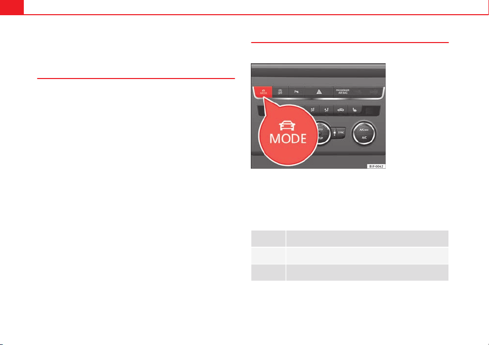
172 Driver assistance systems
The profiles, normal, sport and eco are fixed. Individual can be configured
according to personal preferences.
Description
Depending on the equipment fitted in the vehicle, SEAT Drive Mode can op-
erate on the following functions:
Engine
Depending on the profile selected, the engine responds more spontaneous-
ly or more in harmony with the movements of the accelerator. Additionally,
when eco mode is selected, the Start-stop function is automatically activa-
ted.
In vehicles with DQ transmission, the gear change points are modified to
position them in lower engine speed ranges (eco) or higher (sport). Addi-
tionally, eco mode activates the Inertia function, enabling the consumption
to be further reduced.
In manual vehicles, eco mode causes the gear recommendation indications
that appear on the instrument panel to vary, facilitating more efficient driv-
ing.
Steering
Power steering becomes more robust in sport mode to enable a more sporty
driving style.
Air conditioning
In vehicles with Climatronic, this can operate in eco mode, especially re-
stricting fuel consumption.
Ambient lighting
The ambient lighting guides located in the interior front door panels of the
Leon FR change colour from white to red when sport mode is activated.
Setting driving mode
You can select from Normal, Sport, Eco and Individual.
Fig. 100 Centre console:
MODE button
The required mode can be selected on the touch screen, in the menu that
opens when the MODE button is pressed.
An icon on the Easy Connect system display informs about the active mode.
The MODE button light remains lit up yellow when the active mode is differ-
ent to normal.
Driving pro-
file
Characteristics
Normal
Offers a balanced driving experience, suitable for everyday
use.
Sport
Provides a complete dynamic performance in the vehicle, en-
abling the user a more sporty driving style.
173Driver assistance systems
Driving pro-
file
Characteristics
Eco
Places the vehicle in a particularly low state of consumption,
facilitating a fuel-saving driving style that is respectful to the
environment.
Individual
Enables some configurations to be modified by pressing the
Profile settings button. The functions that can be adjusted
depend on the equipment fitted in the vehicle.
WARNING
When operating SEAT Drive Mode, pay attention to all traffic. Doing oth-
erwise could cause an accident.
Note
● The vehicle will start in the mode that was selected at the moment it was
switched off.
● Changing modes can alter vehicle handling. The SEAT Drive Mode func-
tion does not allow configurations that compromise safety under any cir-
cumstances.
● Your speed and driving style must always be adjusted to visibility,
weather, and traffic conditions.
● The eco mode is not available when towing a trailer.
Tiredness detection (break
recommendation)*
Introduction
The Tiredness detection informs the driver when their driving behaviour
shows signs of fatigue.
Additional information and warnings:
● Easy Connect system ⇒ page 79
● Accessories, change a part, repairs and adjustments (information stored
in the control units) ⇒ page 230
WARNING
Do not let the comfort afforded by the Tiredness detection system tempt
you into taking any risks when driving. Take regular breaks, sufficient in
length when making long journeys.
● The driver always assumes the responsibility of driving to their full
capacity.
● Never drive if you are tired.
● The system does not detect the tiredness of the driver in all circum-
stances. Consult the information in the section ⇒ page 174, System limi-
tations.
● In some situations the system may incorrectly interpret an intended
driving manoeuvre as driver tiredness.
● No warning is given in the event of the effect called microsleep!
● Please observe the indications on the instrument panel and act as is
necessary.
Safety First Operating instructions Practical Tips Technical specifications
174 Driver assistance systems
Note
● Tiredness detection has been developed for driving on motorways and
well paved roads only.
● If there is a fault in the system, have it checked by a specialised work-
shop.
Function and operation
Fig. 101 On the instru-
ment panel display:
Tiredness detection sym-
bol
Tiredness detection determines the driving behaviour of the driver when
starting a journey, making a calculation of tiredness. This is constantly com-
pared with the current driving behaviour. If the system detects that the driv-
er is tired, an audible warning is given with a sound and an optic warning is
shown with a symbol and complementary message on the instrument panel
display
⇒
Fig. 101. The message on the instrument panel display is shown
for about 5 seconds, and depending on the case, is repeated. The system
stores the last message displayed.
The message on the instrument panel display can be switched off by press-
ing the
button on the windscreen wiper lever or the button
on the
multi function steering wheel
⇒
page 73.
The message can be recalled to the instrument panel display using the mul-
tifunction display ⇒ page 73.
Conditions of operation
Driving behaviour is only calculated on speeds above about 65 km/h (40
mph) up to around 200 km/h (125 mph).
Switching on and off
Tiredness detection can be activated or deactivated in the Easy Connect
system with the button
and the function button
⇒ page 79. A mark
indicates that the adjustment has been activated.
System limitations
The Tiredness detection has certain limitations inherent to the system. The
following conditions can limit the Tiredness detection or prevent it from
functioning.
● At speeds below 65 km/h (40 mph)
● At speeds above 200 km/h (125 mph)
● When cornering
● On roads in poor condition
● In unfavourable weather conditions
● When a sporty driving style is employed
● In the event of a serious distraction to the driver
Tiredness detection will be restored when the vehicle is stopped for more
than 15 minutes, when the ignition is switched off or when the driver has
unbuckled their seat belt and opened the door.
In the event of slow driving during a long period of time (below 65 km/h (40
mph) the system automatically re-establishes the tiredness calculation.
When driving at a faster speed the driving behaviour will be recalculated.
175Driver assistance systems
Tyre monitoring systems
Introduction
Additional information and warnings:
● SEAT information system ⇒ page 73
● Caring for and cleaning the vehicle exterior ⇒ page 198
● Wheels and tyres ⇒ page 223
● Accessories, parts replacement, repairs and modifications ⇒ page 230
WARNING
Unsuitable handling of the wheels and tyres may lead to sudden tyre
pressure losses, to tread separation or even to a blow-out.
● Check tyre pressures regularly and ensure they are maintained at the
pressures indicated. Tyre pressure that is too low could cause overheat-
ing, resulting in tread detachment or even burst tyres.
● Tyre pressure should be that indicated on the label when the tyres are
cold at all times ⇒ page 266.
● Regularly check the cold inflation pressure of the tyres. If necessary,
change the tyre pressure of the vehicle tyres while they are cold.
● Regularly check your tyres for damage and wear.
● Never exceed the maximum permitted speed or loads specified for the
type of tyre fitted on your vehicle.
For the sake of the environment
Under-inflated tyres lead to increased fuel consumption and tyre wear.
Note
● Driving for the first time with new tyres at a high speed can cause them
to slightly expand, which could then produce an air pressure warning.
● Only replace used tyres with those authorised by SEAT for the corre-
sponding type vehicle.
● Do not only rely on the tyre monitoring system. Regularly check your
tyres to ensure that the tyre pressure is correct and that the tyres are not
damaged due to puncture, cuts, tears and impacts/dents. Remove objects
from the tyres only when they have not pierced the tyres.
Tyre monitor indicator warning lamp
lights up Possible cause Solution
The pressure in one or more
tyres has clearly reduced in
comparison to the tyre pres-
sure set by the driver or the
tyre has structural damage.
Additionally, an audible
warning can be heard and a
text message can be seen on
the instrument panel display.
Stop the vehicle! Reduce
speed immediately! Stop the
vehicle safely as soon as
possible. Avoid sudden ma-
noeuvres and braking! Check
all tyres and pressures. Re-
place any damaged tyres.
flashes Possible cause Solution
System malfunction. The
control lamp flashes for
about one minute and then
lights up permanently.
If the tyre pressure is correct,
switch the ignition off and on
again. If the control lamp re-
mains lit up, the tyre monitor-
ing indicator can be calibra-
ted. Have the system re-
viewed by a specialised
workshop.
Safety First Operating instructions Practical Tips Technical specifications
176 Driver assistance systems
Several warning and control lamps light up for a few seconds when the igni-
tion is switched on while the function is verified. They will switch off after a
few seconds.
WARNING
When the tyres are inflated at different pressures or at a pressure that is
too low then a tyre may the damaged resulting in a loss of control of the
vehicle and a serious or fatal accident.
● If the warning lamp lights up, stop immediately and check the
tyres.
● If the tyres are inflated at different pressures or if a tyre pressure is
too low, this will increase tyre wear, negatively affecting vehicle stability
and increasing braking distances.
● If tyres are inflated at different pressures or a tyre pressure is too low,
a tyre may be damaged and burst resulting in a loss of control of the ve-
hicle.
● The driver is responsible for ensuring that all of the vehicle tyres are
correctly inflated to the right pressure. The recommended tyre pressure
is indicated on the label ⇒ page 266.
● The tyre monitoring system can only operate correctly if all of the
tyres are inflated to the correct pressure when cold.
● Driving with tyres at the wrong pressure can cause them damage and
result in an accident. Ensure that the tyre pressures of all the tyres corre-
spond to the vehicle load.
● Before starting a journey, always inflate tyres to the correct pressure.
● Tyres with insufficient pressure are subjected to more flexing. Due to
this, the tyre could become excessively hot, causing tread separation
and also tyre blow-out.
● With an overloaded vehicle at high speed, the tyres can overheat and
burst resulting in a loss of vehicle control.
WARNING (Continued)
● Tyre pressures which are too high or too low reduce the useful life of
the tyre, affecting vehicle performance.
● If a tyre has not been punctured then it does not have to be changed
immediately; drive to the nearest specialised workshop at a moderate
speed and have the tyre checked and inflated to the correct pressure.
WARNING
If the warning lamps and messages are ignored, the vehicle may stall in
traffic, or may cause accidents and severe injuries.
● Never ignore the warning lamps or text messages.
● Stop the vehicle safely as soon as possible.
CAUTION
Failure to heed the control lamps and text messages when they appear may
result in faults in the vehicle.
Note
● If excessively low tyre pressure is detected with the ignition on, an audi-
ble warning will sound. In the event that there is a fault in the system, an
audible warning will sound.
● Driving on dirt tracks for a long period of time or driving in a sporty style
can temporarily deactivate the TPMS. The control lamp shows a fault, but
disappears when road conditions or the driving style change.
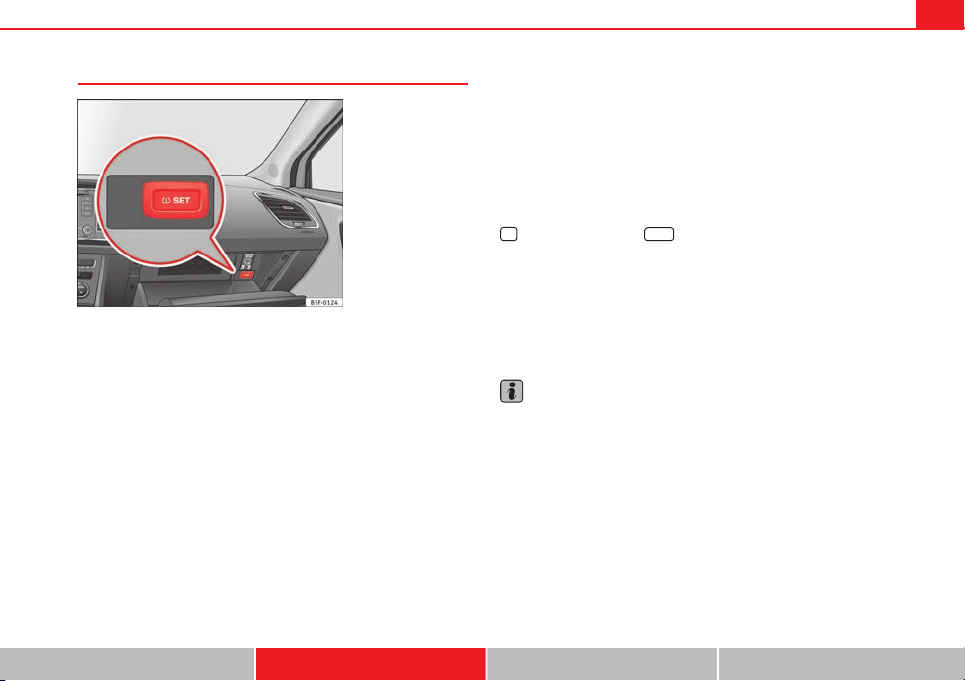
177Driver assistance systems
Tyre monitoring indicator
Fig. 102 Glove compart-
ment: tyre control switch
The tyre monitor indicator compares wheel revolutions and, with this infor-
mation, the tread of each wheel using the ABS sensors. If the tread of one or
more wheels is changed, the tyre monitoring indicator will indicate as such
on the instrument panel.
Wheel tread change
The wheel tread changes when:
● Tyre pressure is manually changed
● Tyre pressure is insufficient
● Tyre structure is damaged
● The vehicle is unbalanced because of a load
● The wheels on an axle are subject to a heavier load (e.g. when towing a
heavy load)
● The vehicle is fitted with snow chains
● The temporary spare wheel is fitted
● The wheel on one axle is changed
There may be a delay in the reaction of the tyre monitoring indicator or it
may not indicate anything under certain circumstances (e.g. sporty driving,
snow-covered or unpaved roads, or when driving with snow chains).
Calibrating the tyre monitoring indicator
After changing the tyre pressure or replacing one or more wheels, the tyre
monitoring indicator must be recalibrated. Do the same, for example, when
the front and rear wheels are swapped.
● Switch the ignition on.
● Store the new tyre pressure in the Easy Connect system with the button
and the function button
Setup
⇒ page 80 or using the switch located in
the glove compartment* ⇒ Fig. 102.
When driving, the system self-calibrates the tyre pressure provided by the
driver and the wheels fitted. After a long journey with varied speeds the pro-
grammed values are collected and monitored.
With the wheels under very heavy loads, the tyre pressure must be in-
creased to the total recommended tyre pressure before the calibration
⇒ page 266.
Note
● The tyre monitoring indicator does not function when there is a fault in
the ESC or ABS ⇒ page 183.
● An erroneous indication may be given when snow chains are in use be-
cause the chains increase the tread of the wheel.
Safety First Operating instructions Practical Tips Technical specifications
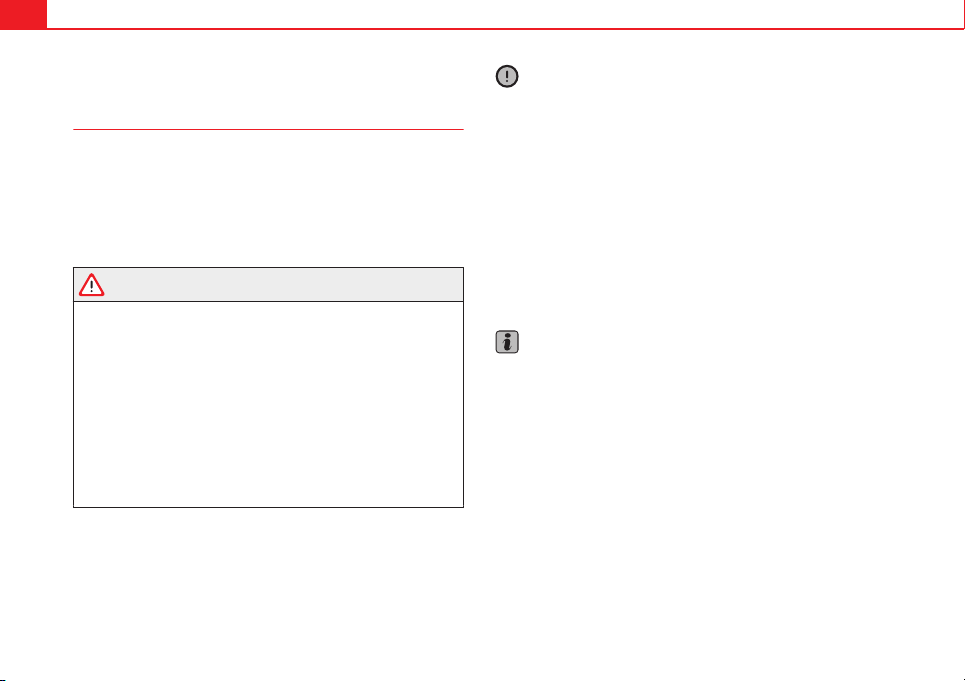
178 Driver assistance systems
Parking aid
General information
Various systems are available to help you when parking or manoeuvring in
tight spaces, depending on the equipment fitted on your vehicle.
The rear parking aid is an audible assistant that warns about obstacles lo-
cated behind the vehicle ⇒ page 179.
During parking, the plus parking aid assists you visually and audibly about
obstacles detected in front and behind the vehicle ⇒ page 179.
WARNING
● Always pay attention (also when looking straight ahead) to traffic and
the vehicle surroundings. The assistance systems are not a replacement
for driver awareness. When inserting or removing the vehicle from a park-
ing space, or when performing similar manoeuvres the driver always as-
sumes the responsibility.
● Take into account that the system is not always in conditions to rec-
ognise or represent certain surfaces, such as dress fabric: Risk of causing
an accident!
● The sensors and cameras have blind spots, making the detection of
people and objects impossible. Pay special attention to children and ani-
mals: Risk of causing an accident!
● Always keep visual control of the vehicle surroundings: use the rear
vision mirrors for additional help.
CAUTION
● Under certain circumstances, the system does not detect or display cer-
tain objects:
– Objects such as snow chains, trailer draw bars, bars or fences
– Objects that are located above the sensors, such as protrusions in a
wall.
– Objects with certain surfaces or structures, such as wire mesh fences
or powder snow.
● When the vehicle approaches a low obstacle, it could disappear from
the angle of measurement. In this case, take into account that the system
will no longer warn about this obstacle.
● The knocks or damage on the radiator grille, bumper, wheel arch and ve-
hicle underbody can adjust the orientation of the sensors. This can affect
the parking aid function. Have the function checked by a specialised work-
shop.
Note
● In certain situations, the system can give a warning even though there is
no obstacle in the detected area, e.g:
– for roads with certain surfaces, or with long grass
– for external ultrasound sources, such as cleaning vehicles
– In downpours, intense snow or dense exhaust gases
● In order to familiarise yourself with the system, it is advised that you
practice parking in an area or car park that is free from traffic. There must be
good weather and light conditions.
● The volume and tone of the warnings can be modified, in addition to the
indications ⇒ page 181.
● In vehicles without a driver information system, these parameters can be
modified in a SEAT Official Service or in a specialised workshop.
● Please observe information on towing a trailer ⇒ page 182.
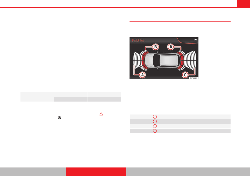
179Driver assistance systems
● The display on the Easy Connect screen shows a slight time delay.
● To ensure that the parking aid works properly, the sensors must be kept
clean and free of ice and snow.
Rear parking aid*
The rear parking aid is an audible assistant.
Description
There are sensors integrated in the rear bumper. When the sensors detect
an obstacle, you are alerted by audible warnings.
Make sure that the sensors are not covered by adhesives, residues and the
like, given that this could affect the system operation. Cleaning instructions
⇒ page 199.
The approximate measurement range of the sensors is:
rear
side 0.90 m
centre 1.60 m
As you approach the obstacle, the time interval between the audible warn-
ings will be reduced. When you reach around 0.30 m the warning will be
constant: Do not continue to move forward (or backward) ⇒
in General
information on page 178, ⇒
in General information on page 178 !
If you maintain separation from the obstacle, the volume of the warning be-
gins to reduce after four seconds (does not affect the tone of the constant
warning).
Activate
When engaging reverse gear, the parking aid is automatically switched on.
This is confirmed with a short warning.
Plus parking aid*
Plus parking aid assists you audibly and visually when park-
ing.
Fig. 103 Represented
area
There are sensors integrated in the front and rear bumpers. When the sen-
sors detect an obstacle, audible and visual warnings are given.
Make sure that the sensors are not covered by adhesives, residues and the
like, given that this could affect the system operation. Cleaning instructions
⇒ page 199.
The approximate measurement range of the sensors is:
A
1.20 m
B
0.90 m
C
1.60 m
D
0.90 m
As you approach the obstacle, the time interval between the audible warn-
ings will be reduced.
If you maintain separation from the obstacle, the volume of the warning be-
gins to reduce after four seconds (does not affect the tone of the constant
warning).
Safety First Operating instructions Practical Tips Technical specifications
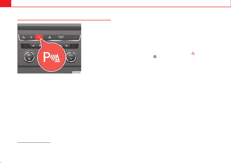
180 Driver assistance systems
Activating/Deactivating
Fig. 104 Centre console:
parking aid button
Switching on
– Engage reverse gear or
– Press the button on the centre console ⇒ Fig. 104. A short
confirmation signal will be heard and the button symbol will
light up yellow.
Switching off
– Drive forwards at more than 10 km/h (6 mph), or
– Press the
button, or
– Switch the ignition off
Segments of the visual indication
The distance of separation from the obstacle can be estimated using the
segments around the vehicle. With certain equipment (Radio Standard), the
yellow lines* mark the estimated path, depending on the angle of the
turned steering wheel. A white segment is seen when an obstacle is detec-
ted out of the path of the vehicle. The red segments represent obstacles de-
tected within the path. As the vehicle approaches an obstacle, the seg-
ments are displayed closer to the vehicle. When the penultimate segment is
displayed, this means that the vehicle has reached the collision zone. In the
collision zone the obstacles are represented in red, including those out of
the path. Do not continue to move forward (or backward) ⇒
in General
information on page 178, ⇒
in General information on page 178 !
Automatic activation
1)
When the parking aid (ParkPilot) is automatically switched on this is shown
in miniature on the left side of the display.
When slowly approaching an obstacle located in front of the vehicle, the au-
tomatic activation only functions each time the speed is reduced below ap-
proximately 10 km/h (6 mph) for the first time. If the parking aid is deactiva-
ted using the button, the following actions must be carried out in order
for it to automatically reactivate:
● Switch off the ignition and switch it on again.
● ALTERNATIVELY: Accelerate above 10 km/h (6 mph) before reducing
speed below this number again.
● ALTERNATIVELY: Place the selector lever in position P and then move it
from this position.
● ALTERNATIVELY: Switch on and off the automatic activation in the Easy
Connect system menu.
The automatic activation with parking aid miniature indication can be
switched on and off from the Easy Connect system menu ⇒ page 81:
1)
Available only with certain equipment.
181Driver assistance systems
● Switch the ignition on.
● Press button
.
● Press the
Setup
function button.
● Press the
Parking and Manoeuvring
function button.
● Select the parking aid (ParkPilot) from the list.
● Automatic activation.
When the function button check box is activated , the function is on.
Adjusting the display and audible warnings
The settings for the display and audible warnings are con-
trolled via the Easy Connect*.
Requirements: the parking aid must be switched on.
– Select: button
CAR
> control button Car* Systems > Driver assis-
tant > Parking aid ⇒ page 81.
Automatic activation
1)
on – activates the Automatic activation option ⇒ page 180
off – deactivates the Automatic activation option ⇒ page 180.
Front volume
Volume in the front and rear area.
Front sound settings
Frequency (tone) of the sound in the front area.
Rear volume
Volume in the rear area
Rear sound settings
Frequency (tone) of the sound in the rear area.
Adjust volume
With the parking aid switched on, the active audio/video source volume will
be reduced to the intensity of the selected setting.
You will hear a short test tone from the corresponding speaker each time
you make a new setting.
Error messages
When the parking aid is activated or when switching it on, if a continuous
warning can be heard over several seconds (additionally, in the case of Plus
parking aid the LED of the button flashes), there is a fault in the system.
If the fault does not disappear before switching off the ignition, the next
time the parking aid is switched on by engaging reverse gear the fault will
only be indicated with the flashing LED on the button.
Plus parking aid*
If there is a fault in a sensor, the symbol is displayed on the Easy Con-
nect display in front of/behind the vehicle. If a rear sensor is faulty, only the
obstacles in the areas
A
and
B
are displayed ⇒ Fig. 103. If a front sensor
is faulty, only the obstacles in the areas
C
and
D
are displayed.
Have the fault corrected by a specialised workshop without delay.
1)
available only with certain equipment - Radio Standard
Safety First Operating instructions Practical Tips Technical specifications

182 Driver assistance systems
Towing bracket
If the trailer power socket is occupied, the rear parking aid sensors will not
activate when reverse gear is engaged, or when the button is pressed.
This function may not be covered under warranty if the towing bracket is not
factory-fitted. This causes the following limitations:
Plus parking aid*
There will be no warning about the presence of obstacles in the rear area.
The monitoring in the front area remains active. The optical display changes
to towing mode.

183Intelligent technology
Practical Tips
Intelligent technology
Electronic Stability Control (ESC)
Description
EI ESC helps to improve safety. It reduces the tendency to skid and improves
the stability and roadholding of the vehicle. EI ESC detects critical handling
situations, such as vehicle understeer or oversteer, or wheelspin on the
driving wheels. It stabilises the vehicle by braking individual wheels or by
reducing the engine torque. The warning lamp will flash on the instrument
panel when the ESC is intervening .
ESC includes the Anti-lock brake system (ABS), the brake assist system, the
traction control system (ASR), electronic differential lock (EDL), electronic
self-locking*, selective torque control* and tractor-trailer sway mitigation*.
ESC also helps stabilise the vehicle by changing the torque.
Anti-lock brake system (ABS)
ABS prevents the wheels from locking up under braking until the vehicle
has reached a virtual standstill. You can continue to steer the vehicle even
when the brakes are on full. Keep your foot on the brake pedal and do not
pump the brakes. You will feel the brake pedal pulsate while the ABS is
working.
Brake assist system
The brake assist system can reduce the required braking distance. The brak-
ing force is automatically boosted if you press the brake pedal quickly in an
emergency. You must keep pressing the brake pedal until the danger has
passed.
Traction control system (ASR)
In the event of wheelspin, the traction control system reduces the engine
torque to match the amount of grip available. This helps the car to start
moving, accelerate or climb a gradient.
Electronic differential lock (EDL)
When the EDL detects wheelspin, it brakes the spinning wheel and directs
the power to the other driven wheel. This function is available up to a speed
of around 100 km/h, 62 mph).
To prevent the disc brake of the braked wheel from overheating, the EDL
cuts out automatically if subjected to excessive loads. The vehicle can still
be driven. The EDL will switch on again automatically when the brake has
cooled down.
Tractor-trailer sway mitigation*
If the vehicle is pulling a trailer, it will control the following: Tractor-trailers
tend to sway. When the swaying of the trailer is felt by the vehicle and de-
tected by the ESC, it will automatically brake the towing vehicle within the
limits of the system and mitigate the sway. Tractor-trailer sway mitigation is
not available in all countries.
Electronic self-locking*/Selective torque control*
When driving around bends, an electronic self-locking intervenes. The front
wheel on the inside of the curve, or the two inside wheels, respectively, are
selectively braked as required. This minimises the traction of the front
wheels, allowing you to take bends with greater precision and neutrality. In
certain circumstances, where roads are wet or snow-covered, the respective
system may not intervene.
Safety First Operating instructions Practical Tips Technical specifications
184 Intelligent technology
Multi-collision brake
In an accident, the multi-collision brake can help the driver by braking to
avoid the risk of skidding during the accident, which could lead to further
collisions.
The multi-collision brake works for front, side or rear accidents, when the
airbag control unit records its activation level and the accident takes place
at a speed of over 10 km/h (6 mph). The EI ESC automatically brakes the
vehicle, as long as the accident has not damaged the ESC, the brake hy-
draulics or the on-board network.
The following actions control automatic braking during the accident:
● When the driver presses the accelerator. The automatic braking does not
take place.
● When the braking pressure through pressing the brake pedal is greater
than the system’s braking pressure. The vehicle will brake manually.
● Multi-collision braking will not be available if ESC is malfunctioning.
WARNING
● Nor can the ESC, ABS, ASR, EDL, electronic self-locking differential or
selective torque control systems exceed the limits imposed by the laws
of physics. Always bear this in mind, especially on wet or slippery roads.
If you notice the systems cutting in, you should reduce your speed imme-
diately to suit the road and traffic conditions. Do not be encouraged to
take risks by the presence of more safety systems. If you do, an accident
may occur.
● Please remember that the accident risk always increases if you drive
fast, especially in corners or on a slippery road, or if you follow too close
behind the vehicle in front of you. The ESC, ABS, brake assist, EDL, elec-
tronic self-locking and selective torque control systems cannot prevent
accidents: risk of accidents!
● Accelerate with caution on slippery surfaces (for example, icy or
snow-covered). Despite the control systems, the driven wheels could
spin, affecting the stability of the vehicle: risk of accident!
Note
● The ABS and ASR will only operate correctly if the four wheels have iden-
tical tyres. Any differences in the rolling radius of the tyres can cause the
system to reduce engine power when this is not desired.
● The regulating processes of the systems can make noises when they in-
tervene.
● If the warning lamp lights up, or alternatively, there could be a
fault ⇒ page 69.
Switching on/off the ESC and ASR
The ESC is switched on automatically when the engine is
started. The ESC cannot be deactivated.
ESC in "Sport" mode
Sport mode is activated through the Easy Connect system ⇒ page 79 menu.
The ability of the ESC to stabilise the vehicle is limited; the traction control
system (ASR) becomes disabled ⇒
.
The control lamp will light up. For vehicles with a driver information sys-
tem*, the driver will be shown the electronic stability control (ESC) option:
sport. Warning! Limited stability.
In the following exceptional circumstances enabling the ESC Sport mode to
improve the traction of the wheels is tenable:
● when rocking the vehicle backwards and forwards to free it.
● Driving in deep snow or on loose surfaces.
Disable ESC Sport mode
Through the Easy Connect system ⇒ page 79. The warning lamp will
switch off. For vehicles with a driver information system*, the driver will be
shown the electronic stability control (ESC) option: on.
185Intelligent technology
Disable ASR
ASR can be disabled through the Easy Connect system ⇒ page 79 or by
pressing the
OFF
button. The traction control system will be disabled.
The control lamp will light up. For vehicles with a driver information sys-
tem* the driver will be informed that ASR is disabled.
In the following exceptional circumstances enabling the ESC Sport mode to
improve the traction of the wheels is tenable:
● when rocking the vehicle backwards and forwards to free it.
● Driving in deep snow or on loose surfaces.
Activate ASR
ASR can be switched on through the Easy Connect system ⇒ page 79 or by
pressing the
OFF
button. The traction control system will be enabled.
The control lamp switches off. For vehicles with a driver information sys-
tem* the driver will be informed that ASR is enabled.
WARNING
You should switch on the ESC Sport mode only if the traffic conditions
and your driving ability allow you to do so safely: risk of skidding!
● With ESC in Sport mode, the stabilising function will be limited to al-
low for a sportier drive. The driving wheels could spin and the vehicle
could skid.
Note
● ESC Sport mode cannot be activated if the cruise control* actively inter-
venes.
Brakes
New brake pads
For the first 400 km (250 miles), new brake pads have not yet reached their
maximum braking capacity, and need to be “run in” first. However, you can
compensate for the slightly reduced braking effect by applying more pres-
sure on the brake pedal. Avoid overloading the brakes while running them
in.
Wear
The rate of wear on the brake pads depends a great deal on how you drive
and the conditions in which the vehicle is operated. This is a particular
problem in urban traffic and short stretches, or with very sporty driving.
Depending on the speed, the braking force, and the environmental condi-
tions (for example, the temperature, air humidity, etc.) noises may be pro-
duced on braking.
Wet roads or road salt
In certain situations (for example, on driving through flooded areas, in se-
vere downpours or after washing the vehicle) the braking action could be
delayed if the discs and pads are damp, or frozen in winter. In this case the
brakes should be dried by pressing the brake pedal several times.
At high speed and with the windscreen wipers activated, the brake pads will
briefly touch the brake discs. This takes place, although unnoticeable to the
driver, at regular intervals to improve the response time of the brakes when
they are wet.
The effectiveness of the brakes can also be temporarily reduced if the vehi-
cle is driven for some distance without using the brakes when there is a lot
of salt on the road in winter. The layer of salt that accumulates on the discs
and pads can be removed by gently applying the brakes a few times.
Safety First Operating instructions Practical Tips Technical specifications
186 Intelligent technology
Corrosion
There may be a tendency for corrosion to form on the discs and dirt to build
up on the brake pads if the vehicle is used infrequently or the brakes are
not used very often.
If the brakes are not used frequently, or if rust has formed on the disks, it is
advisable to clean off the pads and disks by braking firmly a few times at a
moderately high speed ⇒
.
Fault in the brake system
If the brake pedal travel should ever increase suddenly, this may mean that
one of the two brake circuits has failed. Drive immediately to the nearest
specialised workshop and have the fault repaired. Drive there slowly and re-
member that you will have to apply more pressure on the brake pedal and
allow for longer stopping distances.
Low brake fluid level
Malfunctions can occur in the brake system if the brake fluid level is too
low. The brake fluid level is monitored electronically.
Brake servo
The brake servo increases the pressure you apply to the brake pedal. It
works only when the engine is running.
WARNING
● Apply the brakes heavily to clean the brake system only in a suitable
traffic situation. Do not put other road users in danger: risk of causing an
accident.
● Ensure the vehicle does not move while in neutral, when the engine is
stopped. Failure to do so could result in an accident.
CAUTION
● Never let the brakes “drag” by leaving your foot on the pedal when it is
not necessary to brake. This overheats the brakes, resulting in longer stop-
ping distances and greater wear.
● Before driving down a long, steep gradient, it is advisable to reduce
speed and select a lower gear. This makes use of engine braking and re-
lieves the brakes. If you still have to use the brakes, it is better to brake
firmly at intervals than to apply the brakes continuously.
Note
● If the brake servo is out of action due to a malfunction, or if the car has
to be towed, you will have to press the brake pedal considerably harder to
make up for the lack of servo assistance.
● If you wish to equip the vehicle with accessories such as a front spoiler
or wheel covers, it is important that the flow of air to the front wheels is not
obstructed, otherwise the brakes can overheat.
Electro-mechanical steering
Electro-mechanical power steering assists the driver when
steering.
Electro-mechanical power steering adapts electronically to the speed of the
car, torque and turning angle.
If the power steering should fail at any time or the engine is switched off (for
instance when being towed), the car can still be steered. However, more ef-
fort than normal will be required to turn the steering wheel.
Driver warning lamps and messages
(in red) Faulty steering! To park the vehicle
187Intelligent technology
If the warning lamp remains on and the driver indication appears, the power
steering could be faulty.
Do not continue driving. Seek specialist assistance.
(in yellow) Steering: System fault! You may continue driving.
If the warning lamp comes on, the steering could react with more difficultly
or more sensitivity than normal. In addition, when driving in a straight line
the steering wheel may be off-centre.
Drive slowly to a specialised workshop and have the fault repaired.
(in yellow) Steering lock: fault! Go to an Official Service
The electronic steering lock is malfunctioning.
Go to a specialised workshop as soon as possible and have the fault re-
paired.
WARNING
Take it immediately to a specialised workshop and have the fault re-
paired: risk of accident!
Note
If a red or yellow warning lamp come on briefly, you can continue driv-
ing.
Power Management
This system helps to ensure reliable starting
The power management controls the distribution of electri-
cal energy and thus helps to ensure that there is always
enough power available to start the engine.
If a vehicle with a conventional electrical system is left parked for a long
time, the battery will gradually lose its charge because certain electrical
equipment (such as the electronic gearbox lock) continues to draw current
even when the ignition is off. In some cases there may not be enough power
available to start the engine.
Your vehicle is equipped with an intelligent power management system to
control the distribution of electrical energy. This significantly improves relia-
bility when starting the engine, and also prolongs the useful life of the bat-
tery.
The main functions incorporated in the power management system are bat-
tery diagnosis, residual current management and dynamic power manage-
ment.
Battery diagnosis
The battery diagnosis function constantly registers the condition of the bat-
tery. Sensors detect the battery voltage, battery current and battery temper-
ature. This enables the system to calculate the current power level and
charge condition of the battery.
Residual current management
The residual current management reduces power consumption while the ve-
hicle is parked. It controls the supply of power to the various electrical com-
ponents while the ignition is switched off. The system takes the battery di-
agnosis data into consideration.
Safety First Operating instructions Practical Tips Technical specifications

188 Intelligent technology
Depending on the power level of the battery, the individual electrical com-
ponents are switched off one after the other to prevent the battery from los-
ing too much charge and to ensure that the engine can be started reliably.
Dynamic power management
While the vehicle is moving, this function distributes the available power to
the various electrical components and systems according to their require-
ments. The power management ensures that on-board systems do not con-
sume more electrical power than the alternator can supply, and thus main-
tains the maximum possible battery power level.
Note
● The power management system is not able to overcome the given physi-
cal limits. Please remember that the power and useful life of the battery are
limited.
● When there is a risk that the vehicle will not start, the alternator power
failure or low battery charge level warning lamp will be shown
⇒ page 69.
Note carefully
Starting ability has first priority.
Short trips, city traffic and low temperatures all place a heavy load on the
battery. In these conditions a large amount of power is consumed, but only
a small amount is supplied. The situation is also critical if electrical equip-
ment is in use when the engine is not running. In this case power is con-
sumed when none is being generated.
In these situations you will be aware that the power management system is
intervening to control the distribution of electrical power.
When the vehicle is parked for long periods
If you do not drive your vehicle for a period of several days or weeks, the
power management will gradually shut off the on-board systems one by
one, or reduce the amount of current they are using. This limits the amount
of power consumed and helps to ensure reliable starting even after a long
period. Some convenience functions, such as remote vehicle opening, may
not be available under certain circumstances. These functions will be re-
stored when you switch on the ignition and start the engine.
With the engine switched off
For example, if you listen to the sound system with the engine switched off
the battery will run down.
If the energy consumption means there is a risk that the engine will not
start, a text will appear in vehicles with a driver information system*.
This driver indicator tells you that you must start the engine so that the bat-
tery can recharge.
When the engine is running
Although the alternator generates electrical power, the battery can still be-
come discharged while the vehicle is being driven. This can occur when a
lot of power is being consumed but only a small amount supplied, especial-
ly if the battery is not fully charged initially.
To restore the necessary energy balance, the system will then temporarily
shut off the electrical components that are using a lot of power, or reduce
the current they are consuming. Heating systems in particular use a large
amount of electrical power. If you notice, for instance, that the seat heating*
or the heated rear window is not working, they may have been temporarily
switched off or regulated to a lower heat output. These systems will be
available again as soon as sufficient electrical power is available.
You may also notice that the engine runs at a slightly faster idling speed.
This is quite normal, and no cause for concern. The increased idling speed
allows the alternator to meet the greater power requirement and charge the
battery at the same time.
189Intelligent technology
Information recorded in the control units
Your vehicle is fitted at the factory with a series of electronic control units
responsible for the engine and gearbox management. In addition, the con-
trol units supervise the correct performance of the exhaust gas system and
the airbag systems.
Therefore, while the vehicle is being driven, these electronic control units
are continuously analysing the vehicle data. In the event of faults or devia-
tions from the theoretical values, only this data is stored. Generally, the in-
strument panel warning lamps indicate whether there are any malfunctions.
This data can only be read and analysed using special equipment.
The storing of the data allows specialised workshops to detect and repair
faults. Stored data may include:
● Important data about the engine and gearbox
● Speed
● Direction of travel
● Braking force
● Seat belt check
The vehicle control units never record conversations held by passengers in
the vehicle.
If the control unit records an accident with airbag activation, the system
may automatically send a signal. This will depend on the network operator.
Normally, transmission is only possible in areas with sufficient coverage.
Event Data Recorder
The vehicle is not fitted with an event data recorder.
An event data recorder temporarily stores the vehicle information. There-
fore, in the event of accident, it is possible to obtain detailed information
about how the accident occurred. For example, in vehicles with airbag sys-
tems, data relating to speed of impact, seat belt status, seat positions and
airbag activation times may be stored. The volume of data depends on the
manufacturer.
Event data recorders can only be mounted with authorisation from the vehi-
cle owner and, in some countries, they are governed by local legislation.
Reprogramming control units
On the whole, all the data required for the component management is stor-
ed in the control units. The programming of certain convenience functions,
such as the turn signal convenience mode, individual door opening and dis-
play indications can be modified using special equipment at the workshop.
If the convenience functions are reprogrammed, the Instruction Manual in-
formation and descriptions will not coincide with the modified functions.
Therefore, SEAT recommends that any changes are recorded in the “Other
workshop notes section” of the Service Plan.
You can find out about possible reprogramming at your SEAT Official Serv-
ice.
Event recorder
In the footwell on the driver side you will find the diagnostics connection
socket for reading the event recorder. The event recorder stores operating
data and data on the status of the electronic control units. The events re-
corder should only be read and deleted by a SEAT Official Service or special-
ised workshop.
WARNING
The diagnostics connection socket must not be used for private purpo-
ses. Improper use can cause malfunctions: risk of accident!
Safety First Operating instructions Practical Tips Technical specifications
190 Driving and the environment
Driving and the environment
Running in the engine
A new vehicle should be run in over a distance of 1500 km (1000 miles). For
the first 1000 km (600 miles) the engine speed should not exceed 2/3 of
the maximum permissible engine speed. In doing so, do not accelerate at
full throttle and do not drive with a trailer! From 1000 to 1500 km (600 to
1000 miles) you can gradually increase the engine rpm and road speed.
During its first few hours of running, the internal friction in the engine is
greater than later on when all the moving parts have bedded down.
How the vehicle is driven for the first 1500 km (1000 miles) influences the
future engine performance. Subsequently, also drive at a moderate rate, es-
pecially when the engine is still cold: this will lead to less engine wear and
tear and will prolong its useful life.
You should also avoid driving with the engine speed too low. Change down
to a lower gear when the engine no longer runs “smoothly”. If the engine
revs too much, cut fuel injection to protect the engine.
Driving through flooded roads
To prevent damage to the vehicle when driving through water, for example,
along a flooded road, please observe the following:
● The water should never come above the lower edge of the bodywork.
● Drive at pedestrian speed.
WARNING
After driving through water, mud, sludge, etc., the braking effect can be
delayed slightly due to moisture build-up on the discs and brake pads.
Applying the brakes carefully several times will remove the moisture and
restore the full braking effect.
CAUTION
● Driving through flooded areas may severely damage vehicle compo-
nents such as the engine, transmission, running gear or electrical system.
● Whenever driving through water, the Start-Stop system* must be switch-
ed off ⇒ page 149.
Note
● Check the depth of the water before entering the flooded zone.
● Do not stop in the water, drive in reverse, or stop the engine in any sit-
uation.
● Note that vehicles travelling in the opposite direction may splash water
that could exceed the maximum permitted water height for your vehicle.
● Avoid driving through salt water (corrosion).
Installation of exhaust gas filtration systems
Catalytic converter
Applies to vehicles with petrol engine: The vehicle must only be used with
unleaded petrol, otherwise the catalytic converter will be irreparably dam-
aged.
191Driving and the environment
Never drive until the tank is empty; an irregular supply of fuel can cause
faulty combustion. In these cases, unburned fuel reaches the exhaust sys-
tem, which can overheat and damage the catalytic converter.
Diesel particulate filter
Applies to vehicles with diesel engine: The diesel particulate filter can filter
out almost all soot particles contained in the exhaust gas. In normal driving
conditions the filter is self-cleaning. The Diesel particulate filter is cleaned
automatically without need for indication by the warning lamp . This may
be noticed because the engine idle speed increases and an odour may be
detected.
If automatic filter purification cannot be carried out (because only short
trips are taken, for example), soot will accumulate on the filter and the Die-
sel particulate filter warning lamp will switch on.
Facilitate the automatic filter cleaning process by driving in the following
manner: Drive for approximately 15 minutes at a minimum speed of 60 km/
h (40 mph) in 4th or 5th gear (automatic gearbox: gear S). Maintain the en-
gine speed at approx. 2000 rpm. The rise in temperature causes the soot on
the filter to burn. On completion of the cleaning the warning lamp will
switch off. If the warning lamp does switch off, go immediately to a special-
ised workshop to rectify the problem.
WARNING
● Because of the high temperatures which can occur in the exhaust gas
control system (catalytic converter or diesel particulate filter), do not
park the vehicle where the exhaust can come into contact with flamma-
ble materials under the car (e.g. on grass or at the forest edge). Fire haz-
ard!
● Do not apply wax underneath the vehicle around the area of the ex-
haust system: Fire hazard!
Economic and ecological driving
Fuel consumption, environmental pollution and wear to the engine, brakes
and tyres depends largely on driving style. Fuel consumption can be re-
duced by 10-15% with an economical driving style and proper anticipation
of traffic conditions. The following section gives you some tips on lessening
the impact on the environment and reducing your operating costs at the
same time.
Foresight when driving
Acceleration causes the vehicle to consume more fuel. If you think ahead
when driving, you will need to brake less and thus accelerate less. Wherever
possible, let the car roll slowly to a stop, with a gear engaged (for instance
when you can see that the next traffic lights are red). This takes advantage
of the engine braking effect, reducing wear on the brakes and tyres. Emis-
sions and fuel consumption will drop to zero due to the overrun fuel cut-off.
Changing gear to save energy
An effective way of saving is to change in advance to a higher gear. Running
the engine at high rpm in the lower gears uses an unnecessary amount of
fuel.
Manual gearbox: shift up from first to second gear as soon as possible. In
any case, we recommend that you change to a higher gear upon reaching
2000 rpm or so. Choosing the right gear enables fuel savings. Select the
highest possible gear appropriate for the driving situation (the engine
should continue functioning with cyclical regularity).
Automatic gearbox: accelerate gradually and without reaching the “kick-
down” position.
Avoid driving at high speed
Avoid travelling at top speed, whenever possible. Fuel consumption, emis-
sion of harmful gases and noise pollution multiply disproportionately as
speed is increased. Driving at moderate speeds will help to save fuel.
Safety First Operating instructions Practical Tips Technical specifications

192 Driving and the environment
Reduce idling time
In vehicles with the Start-Stop system idling is automatically reduced. In ve-
hicles without the Start-Stop system it is worth switching off the engine, for
example, at level crossings and at traffic lights that remain red for long peri-
ods of time. When an engine has reached operating temperature, and de-
pending on the cylinder capacity, keeping it off after about 5 seconds al-
ready saves more than the amount of fuel necessary for restarting.
The engine takes a long time to warm up when it is idling. Mechanical wear
and pollutant emissions are also especially high during this initial warm-up
phase. It is therefore best to drive off immediately after starting the engine.
Avoid running the engine at high speed.
Regular maintenance
Regular servicing helps in saving fuel even before the engine is started. A
well-serviced engine gives you the benefit of improved fuel efficiency as
well as maximum reliability and an enhanced resale value. A badly serviced
engine can consume up to 10% more fuel than necessary.
Avoid short journeys
The engine and catalytic converter need to reach their optimal operating
temperature in order to minimise fuel consumption and emissions.
A cold engine consumes a disproportionate amount of fuel. The engine only
reaches its working temperature after about four kilometres (2.5 miles),
when fuel consumption will return to a normal level.
Check tyre pressure
Always make sure the tyres are inflated to the correct pressures
⇒ page 223 to save fuel. If the pressure is below half bar, fuel consumption
may increase by 5%. Due to the greater rolling resistance, under-inflation
also increases tyre wear and impairs handling.
Do not use winter tyres all year round as they increase fuel consumption by
up to 10%.
Avoid carrying unnecessary loads
Given that every kilo of extra weight will increase the fuel consumption, it is
advisable to always check the luggage compartment to make sure that no
unnecessary loads are being transported.
Since the luggage rack increases the aerodynamic drag of the vehicle, you
should remove it when not needed. This will save, at a speed of 100-120
km/h (60-75 mph), approximately 12% of fuel.
Save electrical energy
The engine drives the alternator, thereby generating electricity. This implies
that any increase in power consumption also increases fuel consumption!
For this reason, switch off any unneeded consumption of electricity. Electri-
cal equipment which uses a lot of electricity includes the blower (at a high
setting), the rear window heating and the seat heating*.
Environmental friendliness
Environmental protection is a top priority in the design, choice of materials
and production of your new SEAT.
Design measures for economical recycling
● Joints and connections designed for easy dismantling
● Modular construction to facilitate dismantling
● Increased use of single-grade materials
● Plastic parts and elastomers are rated in accordance with ISO 1043, ISO
11469 and ISO 1629
Choice of materials
● Nearly all materials used can be recycled
● Use of suitable plastics within the same system/set
● Recycled materials used in manufacture

193Driving and the environment
● Reduced “vapour emissions” from plastics
● CFC-free refrigerant in air conditioner
Compliance with the laws prohibiting the use of: Cadmium, asbestos, lead,
mercury, chromate.
Manufacturing methods
● Recyclable material for the manufacturing of plastic components
● Solvent-free cavity sealing
● Solvent-free wax for protecting the vehicles in transit
● Solvent-free adhesives
● No CFCs used in production
● Surplus materials used extensively for energy conversion and building
materials
● Overall water consumption reduced
● Heat recovery systems
● Use of water-soluble paints
Safety First Operating instructions Practical Tips Technical specifications
194 Trailer
Trailer
Trailer towing
What do you need to bear in mind when towing a trailer?
Your vehicle may be used to tow a trailer when fitted with the correct equip-
ment.
If you wish to retrofit a towing bracket, consult ⇒ page 196.
Connectors
Your vehicle is fitted with a 12-pin connector for the electrical connection
between the trailer and the vehicle.
If the trailer has a 7-pin plug you will need to use an adapter cable. This is
available in any Technical Service.
Trailer weight/drawbar load
Never exceed the authorised trailer weight. If you do not load the trailer up
to the maximum permitted trailer weight, you can then climb correspond-
ingly steeper slopes.
The maximum trailer weights listed are only applicable for altitudes up to
1000 m above sea level. With increasing altitude the engine power and
therefore the vehicle climbing ability are impaired because of the reduced
air density. The maximum trailer weight has to be reduced accordingly. The
weight of the vehicle and trailer combination must be reduced by 10% for
every further 1000 m (or part thereof). The gross combination weight is the
actual weight of the laden vehicle plus the actual weight of the laden trailer.
When possible, operate the trailer with the maximum permitted drawbar
load on the ball joint of the towing bracket, but do not exceed the specified
limit.
The figures for trailer weights and drawbar loads that are given on the data
plate of the towing bracket are for certification purposes only. The correct
figures for your specific model, which may be lower than these figures for
the towing bracket, are given in the vehicle documentation or in ⇒ chap-
ter Technical Data.
Distributing the load
Distribute loads in the trailer so that heavy objects are as near to the axle as
possible. Loads carried in the trailer must be secured to prevent them mov-
ing.
Tyre pressure
Set tyre pressure to the maximum permissible pressure shown on the stick-
er on the inside of the fuel tank flap. Set the tyre pressure of the trailer tyres
in accordance with the trailer manufacturer's recommendations.
Exterior mirrors
Check whether you can see enough of the road behind the trailer with the
standard rear vision mirrors. If this is not the case, you should have addi-
tional exterior mirrors fitted. Both exterior mirrors should be mounted on
hinged extension brackets. Adjust the mirrors to give sufficient vision to the
rear.
WARNING
Never transport people in a trailer. This could result in fatal accidents.
195Trailer
Note
● Towing a trailer places additional demands on the vehicle. We recom-
mend additional services between the normal inspection intervals if the ve-
hicle is used frequently for towing a trailer.
● Find out whether special regulations apply to towing a trailer in your
country.
Ball coupling of towing bracket*
The ball coupling is provided with instructions on fitting and removing the
ball coupling of the towing bracket.
WARNING
The towing bracket ball coupling must be stored securely in the luggage
compartment to prevent them being flung through the vehicle and caus-
ing injury.
Note
● By law, the ball coupling must be removed if a trailer is not being towed
if it obscures the number plate.
Driving tips
Driving with a trailer always requires extra care.
Weight distribution
The weight distribution of a loaded trailer with an unladen vehicle is very
unfavourable. However, if this cannot be avoided, drive extra slowly to allow
for the unbalanced weight distribution.
Speed
The stability of the vehicle and trailer is reduced with increasing speed. For
this reason, it is advisable not to drive at the maximum permissible speed
in an unfavourable road, weather or wind conditions. This applies especially
when driving downhill.
You should always reduce speed immediately if the trailer shows the slight-
est sign of snaking. Never try to stop the “snaking” by increasing speed.
Always brake in due course. If the trailer has an overrun brake, apply the
brakes gently at first and then, firmly. This will prevent the jerking that can
be caused by locking of trailer wheels. Select a low gear in due course be-
fore going down a steep downhill. This enables you to use the engine brak-
ing to slow down the vehicle.
Reheating
At very high temperatures and during prolonged slopes, driving in a low
gear and high engine speed, always monitor the coolant temperature gauge
⇒ page 69.
Electronic Stability Control*
The ESC* system helps to stabilise the trailer in case of skidding or rocking.
Safety First Operating instructions Practical Tips Technical specifications
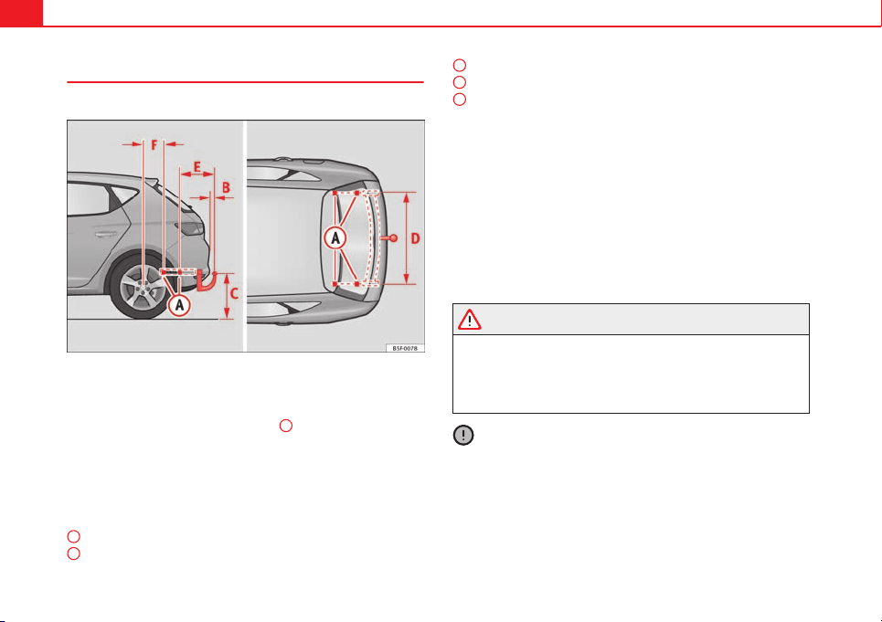
196 Trailer
Retrofitting a towing bracket*
It is possible to fit a towing bracket to the rear of the vehicle.
Fig. 105 Attachment points for towing bracket
If a towing bracket is to be fitted after the vehicle is purchased, this must be
completed according to the instructions of the towing bracket manufacturer.
The attachment points for the towing bracket
A
are on the lower part of the
vehicle.
The distance between the centre of the ball coupling and the ground should
never be lower than the indicated value, even with a fully loaded vehicle
and including the maximum drawbar load.
Elevation values for securing the towing bracket:
65 mm (minimum)
from 350 mm to 420 mm (fully loaded vehicle)
B
C
1040 mm
317 mm
339 mm
Fitting a towing bracket
● Driving with a trailer involves an extra effort for the vehicle. Therefore,
before fitting a towing bracket, please contact a Technical Service to check
whether your cooling system needs modification.
● The legal requirements in your country must be observed (e.g. the fitting
of a separate control lamp).
● Certain vehicle components, e.g. the rear bumper, must be removed and
reinstalled. The towing bracket securing bolts must be tightened using a
torque wrench, and a power socket must be connected to the vehicle electri-
cal system. This requires specialised knowledge and tools.
● Figures in the illustration show the elevation value and the attachment
points which must be considered if you are retrofitting a towing bracket.
WARNING
The towing brackets should be fitted at a specialised workshop.
● If the towing bracket is incorrectly installed, there is a serious danger
of accident.
● For your own safety, please observe the instructions provided by the
manufacturer of the towing bracket.
CAUTION
● If the power socket is incorrectly installed, this could cause damage to
the vehicle electrical system.
D
E
F

197Trailer
Note
● SEAT recommends that the towing hooks be fitted at a specialised work-
shop. In certain versions this may entail fitting a heat insulating plate,
which is why it is recommended that you go to a SEAT Dealer. In the event
that the plate is not installed correctly, SEAT is exempt from any liability.
● Due to the specific design of the exhaust, the fitting of a conventional
towing hook is not recommended for some sportier versions. Please consult
your Technical Service.
Safety First Operating instructions Practical Tips Technical specifications
198 Care and cleaning
Care and cleaning
General information
Regular care helps to maintain the value of the vehicle.
Regular and careful care helps to maintain the value of the vehicle. This may
also be one of the requirements for upholding any warranty claims in the
event of corrosion or paint defects.
SEAT Official Services and specialist retailers carry stocks of suitable car
care materials. Please follow the instructions for use on the packaging.
WARNING
● Cleaning products and other materials used for car care can be dam-
aging to your health if misused.
● Always keep care products in a safe place, out of the reach of chil-
dren. Failure to comply could result in poisoning.
For the sake of the environment
● If possible, use environmentally friendly products.
● The remains of car care products should not be disposed of with ordina-
ry household waste.
Care of vehicle exterior
Washing the vehicle
The longer substances such as insects, bird droppings, resinous tree sap,
road dirt, industrial deposits, tar, soot or road salt and other aggressive ma-
terials remain on the vehicle, the more damage they do to the paintwork.
High temperatures (for instance due to strong sunlight) further intensify the
corrosive effect.
After the period when salt is put on the roads it is important to have the un-
derside of the vehicle washed thoroughly.
Automatic car washes
Before going through a car wash, be sure to take the usual precautions such
as closing the windows and roof. If the vehicle has special accessories such
as spoilers or a roof carrier or two-way radio aerial, etc., it is advisable to
consult the car wash operator.
It is best to use a car wash without revolving bristles if possible.
Washing the vehicle with a high pressure cleaner
When washing the vehicle with a high-pressure cleaner, always follow the
operating instructions for the equipment. This applies particularly to the op-
erating pressure and the spraying distance. Do not hold the nozzle too
close to soft materials such as rubber hoses or seals. The same applies to
the parking aid sensors*, which are located in the rear bumper.
Do not use a nozzle that sprays the water out in a direct stream or one that
has a rotating jet for forcing off dirt.
199Care and cleaning
Washing the car by hand
When washing the car by hand, use plenty of water to soften the dirt first,
and rinse off as well as possible.
Then clean the vehicle with a soft sponge, glove or brush using only slight
pressure. You should start on the roof and work down. Special car shampoo
should only be used for very persistent dirt.
Rinse the sponge or glove thoroughly and often.
Wheels, sills and similar should be cleaned last. Use a second sponge for
this.
WARNING
● The vehicle should only be washed with the ignition switched off.
Failure to do so could result in an accident.
● Do not clean the underside of chassis, the inside of wheel arches or
wheel trims without protecting your hands and arms. You may cut your-
self on sharp-edged metal parts. Otherwise, there is a risk of sustaining
cuts.
● When washing the car during the winter season: water and ice in the
brake system can reduce braking effectiveness: risk of accident!
CAUTION
● Do not wash the vehicle in direct sunlight – otherwise the paint can be
damaged.
● Do not use sponges, abrasive household sponges or similar to clean in-
sect remains. This could damage the surface.
● Clean off stubborn dirt (insects, etc.) from the headlights at regular in-
tervals, for instance when filling the fuel tank. The headlights should only
be washed with water, do not wipe them with a dry cloth or sponge. It is
best to use soapy water.
● Never wash tyres with a jet that sprays the water out in a direct stream.
This could damage the tyres even if the spray is kept at a distance and only
used for a very short time.
● Before washing the vehicle in an automatic car wash, please make sure
to retract the exterior mirrors to prevent them from being damaged. Electri-
cally retractable exterior mirrors must not be folded in or out by hand. Al-
ways use the electrical power control.
For the sake of the environment
The car should only be washed in special wash bays. This prevents oily wa-
ter from getting into the public drains. In some places, washing vehicles
anywhere else may be prohibited.
Sensors and camera lenses
● Use a small brush to remove snow and a de-icer spray to remove ice.
● Clean the sensors with a solvent-free product and a soft, dry cloth.
● Moisten the camera lens using a standard alcohol-based glass cleaning
agent and clean the lens with a dry cloth. The area in front of the active
Lane Assist* lens area is normally cleaned with the windscreen washer.
CAUTION
● When you clean the vehicle with a pressure washer,
– stay a suitable distance from the sensors on the front and rear bump-
ers.
– Do not clean the camera lenses or surrounding area with the pressure
washer.
● Never use warm or hot water to remove snow and ice from the reverse
camera lens, as it could crack the lens.
● Never use abrasive cleaning agents on the lens.
Safety First Operating instructions Practical Tips Technical specifications

200 Care and cleaning
Care and polishing
Care
Waxing protects the paintwork. It is time to apply a good coat of wax when
water no longer forms droplets and rolls off the clean paintwork.
Even if a wax solution is used regularly in the vehicle washing tunnel, it is
advisable to protect the paint with a hard wax coating at least twice a year.
In the summer, you will find it is much easier to remove dead insects (which
accumulate on the bumper and the front of the bonnet) if the car has been
treated with care products recently.
Polishing
Polishing is only necessary if the paint has lost its shine, and the gloss can-
not be brought back by putting on wax.
If the polish does not contain wax, a wax product should be applied after
polishing.
CAUTION
● Do not use polishes and hard wax on painted parts with a matt finish or
on plastic parts.
● Do not apply paint polishes to the side trim that runs around the panor-
amic roof and ends on the windscreen. However, it can be treated with hard
wax.
Trims
In respect for the environment, the silver-plated trims on the body are made
of pure aluminium (they do not contain chrome).
Dirt or marks on the trim mouldings should be removed with a cleaning
product with a neutral PH (do not use a chrome cleaner). Body polish is also
unsuitable for use on trim mouldings. The intensive cleaning fluids often
used before the car goes into a car wash may contain alkaline substances,
which can cause dull or milky patches when they dry out.
SEAT Official Services carry stocks of cleaning products which have been
tested for use on your vehicle and are not harmful to the environment.
Plastic parts
Plastic parts are cleaned with a power washer. If this is not sufficient, plas-
tic parts should only be treated with a special solvent-free plastic cleaning
agent. Do not use paintwork cleaners, polishes or wax on plastic parts.
Carbon components
The carbon parts on your vehicle have a painted surface. They do not need
any special care and are cleaned just like any other painted part
⇒ page 198.
Paint damage
Minor damage to the paint, such as scratches or stone chips, should be
touched up without delay before the metal starts to corrode. Suitable touch-
up brushes or sprays for your car can be obtained from a SEAT Official Serv-
ice.
The number of the original paint finish on the vehicle is given on the data
sticker ⇒ page 264.
If corrosion is already visible it must be thoroughly removed by a special-
ised workshop.
201Care and cleaning
Windows
Clear vision is an essential safety factor.
The windscreen must not be cleaned with insect remover or wax, otherwise
the windscreen wipers will not function properly (juddering).
Traces of rubber, oil, grease or silicone can be removed with a window
cleaning solution or a silicone remover. Wax residue can only be removed
with a special cleaner. Your SEAT Official Service will be able to provide you
with more detailed information.
The windows should also be cleaned on the inside at regular intervals.
Use a separate cloth or chamois to dry the windows. Cloths used for waxing
and polishing contain residues that will cause smears on the glass.
WARNING
Do not use water-repellent coatings on the windscreen. In bad visibility
conditions (e.g. in the rain, dark or with a low sun), these coatings may
cause dazzle: risk of accident! Such coatings can also cause the wind-
screen wiper blades to make noise.
CAUTION
● Remove snow and ice from windows and exterior mirrors with a plastic
scraper only. To avoid scratches caused by dirt on the glass, the scraper
should only be pushed in one direction and not moved to and fro.
● The heating element for the rear window is located on the inner side of
the window. To avoid damaging them, do not apply stickers to the heating
elements.
● Never use warm or hot water to remove snow and ice from windows and
mirrors. This could cause the glass to crack!
Rims
The wheels require regular attention to preserve their appearance. It is im-
portant to remove road salt and brake dust by washing the wheels at regu-
lar intervals, otherwise the finish will be impaired.
After washing, the wheels should only be cleaned with an "acid-free" clean-
ing agent for alloy wheels. This is available from SEAT Official Services and
specialist retailers. Never leave the cleaning agent on the rims for any lon-
ger than specified in the instructions before rinsing it off. If the wheel clean-
er fluid contains acid it can attack the surfaces of the wheel bolts.
Car polish or other abrasive agents should not be used for maintaining the
rims. If the protective coating is damaged, e.g. by stone impact, the dam-
aged area should be touched up immediately.
WARNING
Please note when cleaning the wheels that water, ice and road salt can
impair the effectiveness of the brakes; this can cause an accident.
Exhaust tail pipe
It is important to remove road salt and brake dust by washing the wheels at
regular intervals, otherwise the exhaust tail pipe material could be dam-
aged. To remove impurities, do not use rim, paint or chrome cleaners or oth-
er abrasive products. Clean the exhaust tail pipes with cleaning products
that are suitable for stainless steel.
SEAT Official Services carry stocks of cleaning products that have been tes-
ted and approved for use on your vehicle.
Safety First Operating instructions Practical Tips Technical specifications
202 Care and cleaning
Care of the vehicle interior
Radio display/Easy Connect* and control panel*
The display can be cleaned with a soft cloth and a professionally available
“LCD cleaner”. Moisten the cloth with a small amount of the cleaning fluid.
The Easy Connect control panel* should first be cleaned with a brush so
that no dirt goes into the device or between the keys and housing. Next, we
recommend cleaning the Easy Connect control panel* using a cloth damp-
ened with water and washing-up liquid.
CAUTION
● To avoid scratching the screen, do not wipe the display with a dry cloth.
● To avoid damage, ensure that no liquid goes into the Easy Connect con-
trol panel*.
Plastic and leatherette parts
Plastic parts and leatherette can be cleaned with a damp cloth. If this is not
sufficient, plastic parts and leatherette should only be treated with a special
solvent-free plastic cleaner.
Textile covers and trim parts
Textile covers and trim parts (e.g. seats, door trim) should be cleaned regu-
larly with a vacuum cleaner. This will remove surface dirt which could other-
wise be rubbed into the textile material during use. Do not use steam clean-
ers, as the steam could carry the dirt deeper into the textile material.
Normal cleaning
We recommend that you use a soft sponge or a commercially available lint-
free, micro-fibre cloth for normal cleaning. Only use brushes on floor cover-
ings and mats, as other textile surfaces could become damaged.
In the case of normal surface dirt you can use a foam cleaner. Use a sponge
to spread the foam on the textile surface and to work it into the material
lightly. However, make sure that the textile material does not become soak-
ing wet. Then dab off the foam with a dry and absorbent cloth (e.g. a micro-
fibre cloth) and vacuum off any residue once the surface is completely dry.
Cleaning stains
Treat drink stains (such as coffee or fruit juice, etc.) with a cleaning solution
for delicate fabrics. The cleaning product solution should be applied with a
sponge. If the stains are difficult to remove, a washing paste can be applied
directly onto the stain and worked into the fabric. The surface will then have
to be wiped with clear water to remove any residue left by the paste. To do
so, use a damp cloth or sponge and then dab the stain with an absorbent
cloth.
Remove chocolate or make-up stains with a cleaning paste (for e.g., soft
soap). Then remove the soap with water (wet sponge).
A spirit-based cleaner can be used to remove grease, oil, lipstick or ball
point pen. Then dab the dissolved grease or colour particles off with an ab-
sorbent cloth or similar. You may also have to treat the stain once more us-
ing washing paste and water.
If the covers or textile trim panels are badly soiled we recommend that you
have them cleaned by a professional cleaning company with a shampoo
and spray.
Note
Open Velcro fasteners on clothes can damage the seat upholstery. Make
sure that Velcro fasteners are closed.

203Care and cleaning
Natural leather
SEAT does everything possible to preserve the genuine qual-
ities of this natural product.
General information
Our range of leathers is large. The main type used is nappa in various forms,
that is, leather with a smooth surface in various different colours.
The amount of dye used determines the appearance and properties of leath-
er. If the leather is left in a more natural state, it retains its typical natural
napped appearance and confers excellent all-weather properties to the
seats. Fine veins, healed scars, insect bites, wrinkles and a subtle variation
in shading remain visible; these are the characteristic features of genuine
natural leather.
Natural napped leather does not have a protective surface coating of dye. It
is therefore somewhat more prone to damage. This should be borne in mind
if children or pets often travel in the car, or if there are other factors that
could lead to damage.
Types of leather with a coloured surface coating are likely to be more resist-
ant to damage. This has a great advantage for day-to-day use. However, this
means that the typical natural characteristics of the surface are less appa-
rent, though this does not affect quality.
Cleaning and care
Due to the natural properties of the specially selected hides employed, the
finished leather has a certain sensitivity to grease and dirt, etc. so a degree
of care is required in everyday use and when looking after the leather. Dark
clothing (especially if damp or incorrectly dyed) may stain leather uphols-
tery. Dust and grit in the pores and seams can scratch and damage the sur-
face. Therefore leather should be cleaned at regular intervals, depending on
the actual amount of use. When they have been in use for a certain time,
your car seats will acquire a typical and unmistakable patina. This is charac-
teristic for leather as a natural product and is a sign of genuine quality.
To maintain the value of natural leather you should note the following
points:
CAUTION
● Avoid exposing leather to direct sunlight for long periods, otherwise it
may tend to lose some of its colour. If the car is left for a prolonged period
in the bright sun, it is best to cover the leather.
● Sharp-edged objects on clothing, such as belts, zip fasteners, rivets or
similar, can also leave permanent scratches and rough marks on the surface
of the leather.
Note
● Use a suitable impregnating cream with ultra-violet protection at regular
intervals and after cleaning. The cream nourishes and moisturises the leath-
er, keeps it supple and able to breathe. It will also form a protective film.
● Clean the leather every 2 to 3 months and remove fresh dirt as soon as
possible.
● Remove stains from fresh ball-pen and other inks, lipstick, shoe cream
and similar stains as soon as possible.
● Preserve the colour of the leather. A special coloured cream will renew
the colour of the leather when required and will eliminate differences in col-
our.
Cleaning and care of leather upholstery
Natural leather requires an extra degree of attention and
care.
Normal cleaning
– Moisten a cotton or woollen cloth with water and wipe over the
leather surfaces.
Safety First Operating instructions Practical Tips Technical specifications

204 Care and cleaning
More stubborn dirt
– More stubborn dirt can be removed using a mild soap solution
(pure liquid soap: two tablespoons dissolved in one litre of wa-
ter).
– Do not let the water soak through the leather or penetrate into
the seams.
– Then wipe off with a soft, dry cloth.
Removal of stains
– Remove fresh water-based stains such as coffee, tea, juices,
blood etc. with an absorbent cloth or kitchen roll, dried-on
stains with the cleaning agent from the care set.
– Remove fresh fat-based stains that have not penetrated the sur-
face such as butter, mayonnaise, chocolate, etc. with an ab-
sorbent cloth or kitchen roll or with the cleaning agent from the
care set.
– Treat fat-based, dried-in stains with grease-dissolving spray.
– Treat less common stains such as ball-pen and other inks, felt-
tip pens, nail polish, dispersion paint, shoe cream etc. with a
special leather stain remover.
Leather maintenance
– The leather should be treated regularly (about twice a year) with
a special leather-care product.
– Apply these products very sparingly.
– Then wipe off with a soft, dry cloth.
Should you have questions regarding the care and cleaning of the leather
upholstery in your vehicle, we recommend that you contact your SEAT Offi-
cial Service. Our representatives will be happy to advise you and tell you
about the product range for leather conservation, for example:
● Cleaning and care set
● Coloured leather-care cream
● Stain remover for ball-pen inks, shoe cream etc.
● Grease dissolving spray
● New products and further developments
CAUTION
On no account use solvents (such as petrol, turpentine), wax polish, shoe
cream or similar materials.
Cleaning Alcantara upholstery
Removing dust and dirt
– Moisten a cloth just a little and wipe down the seat covers.
Removing stains
– Moisten a cloth with lukewarm water or diluted white spirits.
– Dab at the stain. Start at the outside and work inwards.
– Dry the area you have cleaned with a soft cloth.
Do not use leather cleaning products on Alcantara seat covers.
You may use a suitable shampoo on dust and dirt.
Dust and grit in the pores and seams can scratch and damage the surface. If
the car is left standing in the sun for long periods, Alcantara leather should
205Care and cleaning
be protected against direct sunlight to prevent it from fading. However,
slight colour variations will arise in normal use.
CAUTION
● Do not use solvents, wax polish, shoe cream, stain removers, leather
cleaning products or any similar products on Alcantara.
● To avoid damage, stubborn stains should be removed by a specialised
workshop.
● On no account use brushes, hard sponges or similar utensils.
Seat belts
– Keep the seat belts clean.
– For cleaning, use a mild solution of soap and water.
– Check the condition of the seat belts at regular intervals.
The retract function may not operate properly in very dirty belts. Make sure
that the inertia reel seat belts are completely dry before allowing them to
retract.
CAUTION
● Do not remove the seat belts from the vehicle to clean them.
● Do not use chemical cleaning agents on the seat belts, as this can dam-
age the webbing. Ensure that the seat belts do not come into contact with
corrosive fluids.
● If you find any damage to the belt webbing, belt fittings, the belt retrac-
tor or the buckle, the belt in question must be replaced by a specialised
workshop.
Safety First Operating instructions Practical Tips Technical specifications
206 Checking and refilling levels
Checking and refilling levels
Fuel
Types of petrol
The correct grade of petrol is listed inside the fuel tank flap.
The vehicle is equipped with a catalytic converter and must only be run on
unleaded petrol. The petrol must comply with European Standard EN 228 or
German standard DIN 51626-1 and must be unleaded. You can refuel with a
maximum ethanol proportion of 10 % (E10). The types of petrol are differen-
tiated by their octane rating (RON).
The following titles appear on the corresponding adhesive on the fuel tank
flap:
Super unleaded 95 octane or normal 91 octane unleaded petrol
We recommend you use super 95 octane petrol. If this is not available: nor-
mal 91 octane petrol, with a slight decrease in power.
Super unleaded petrol with a minimum of 95 octanes
You should use super petrol with a minimum of 95 octanes.
If super is not available, in an emergency you may refuel with normal 91 oc-
tane petrol. In this case only use moderate engine speeds and a light throt-
tle. Refuel with super as soon as possible.
Super unleaded 98 octane or super 95 octane unleaded petrol
We recommend you use super plus 98 octane petrol. If this is not available:
super 95 octane petrol, with a slight decrease in power.
If super is not available, in an emergency you may refuel with normal 91 oc-
tane petrol. In this case only use moderate engine speeds and a light throt-
tle. Refuel with super as soon as possible.
CAUTION
● Never refuel with fuels containing a large proportion of ethanol (for ex-
ample, E50, E85). This could damage the fuel system.
● Just filling one full tank of leaded fuel or fuel containing other metal ad-
ditives would seriously impair the efficiency of the catalytic converter.
● Only use fuel additives that have been approved by SEAT. Octane boost-
ing or anti-knock additives may contain metal additives that could seriously
damage the engine or the catalytic converter. These additives must not be
used.
● Do not refuel if the filler indicates that the fuel contains metal. LRP (lead
replacement petrol) fuels also contain high concentrations of metal addi-
tives. This could damage the engine!
● High engine speed and full throttle can damage the engine when using
petrol with an octane rating lower than the correct grade for the engine.
Note
● You may use petrol with a high octane number than the one recommen-
ded for your engine.
● In those countries where unleaded petrol is not available, you may refuel
with a fuel with a low lead content.
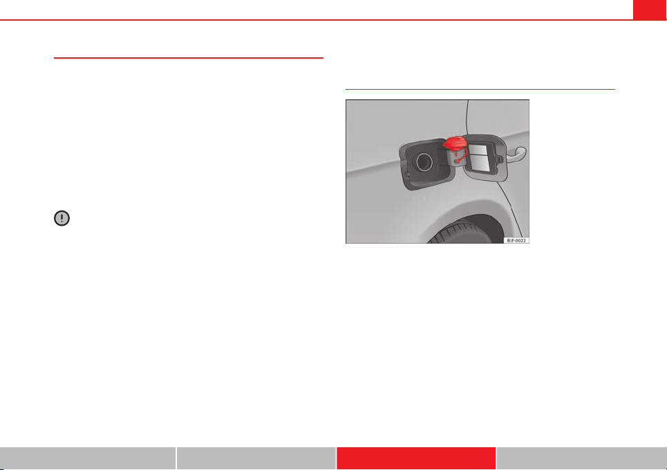
207Checking and refilling levels
Diesel Fuel
Please note the information on the inside of the fuel tank
flap.
We recommend the use of Diesel fuel which complies to European standard
EN 590. If diesel fuel which meets European standard EN 590 is not availa-
ble, the Cetane number (CZ) must, at minimum, be 51. If the engine is
equipped with a particulate filter, the sulphur content of the fuel must be
below 50 parts per million.
Winter-grade diesel
Summer fuel becomes thicker in winter and it is more difficult to start the
engine. For this reason petrol stations in some countries also offer winter
diesel with improved fluidity when cold.
CAUTION
● The vehicle is not designed for the use of biodiesel (FAME fuel). The fuel
system would be damaged if you used biodiesel.
● Do not mix fuel additives, the so-called “thinners”, petrol or similar ad-
ditives with diesel fuel.
● If poor-quality diesel fuel is used, it may be necessary to drain the fuel
filter more frequently than is specified in the Service Plan. We recommend
having this done by a specialised workshop. If water is allowed to collect in
the filter, this can cause engine performance problems.
Filling the tank
Filling the tank
Fig. 106 Fuel tank flap
with tank cap attached
The flap that covers the tank cap is unlocked and locked automati-
cally by the central locking.
Opening the fuel tank cap
– Open the fuel tank flap, by pressing on the left side.
– Unscrew the fuel tank cap anti-clockwise.
– Place the cap in the housing on the hinge of the open flap
⇒ Fig. 106.
Closing the fuel tank cap
– Screw on the tank cap clockwise until it you hear it click into po-
sition.
Safety First Operating instructions Practical Tips Technical specifications
208 Checking and refilling levels
– Close the tank flap. Make sure you hear it click into place.
If the automatic filler nozzle is operated correctly, it will switch itself off as
soon as the fuel tank is “full”. Do not try to put in more fuel after the nozzle
cuts out, as this will fill the expansion chamber in the fuel tank.
The correct fuel grade for your vehicle is given on a sticker on the inside of
the fuel tank flap. Further notes on fuel can be found at ⇒ page 206.
The capacity of the fuel tank is listed in the vehicle technical specifications
⇒ page 276.
WARNING
Fuel is highly flammable and can cause serious burns and other injuries.
● Do not smoke when filling the fuel tank or a canister. Naked flames
are forbidden in the vicinity due to the risk of explosion.
● Observe legislation governing the use, storage and carrying of a
spare fuel canister in the vehicle.
● For safety reasons we do not recommend carrying a spare fuel canis-
ter in the vehicle. In an accident the canister could be damaged and could
leak.
● If, in exceptional circumstances, you have to carry a spare fuel canis-
ter, please observe the following points:
– Never fill fuel into the spare fuel canister if it is inside or on top of
the vehicle. An electrostatic charge could build up during filling, caus-
ing the fuel vapour to ignite. Danger of explosion. Always place the
canister on the ground to fill it.
– Insert the filling nozzle as far as possible into the spare fuel canis-
ter.
WARNING (Continued)
– If the spare fuel canister is made of metal, the filling nozzle must
be in contact with the canister during filling. This helps prevent an
electrostatic charge building up.
– Never spill fuel in the vehicle or in the luggage compartment. Fuel
vapour is explosive. Risk of fatal accident!
CAUTION
● If any fuel is spilt onto the vehicle, it should be removed immediately. It
could otherwise damage the paintwork.
● Never run the tank completely dry. An irregular fuel supply could cause
misfiring. As a result, unburnt fuel could enter the exhaust system and dam-
age the catalytic converter.
● When filling the fuel tank after having run it completely dry on a vehicle
with a diesel engine, the ignition must be switched on for at least 30 sec-
onds before starting the engine. When you then start the engine it may take
longer than normal (up to one minute) for the engine to start firing. This is
because air needs to be bled from the fuel system while starting.
For the sake of the environment
Do not overfill the fuel tank – it may cause the fuel to overflow if it becomes
warm.
209Checking and refilling levels
Note
Diesel vehicles are fitted with a protective device that prevents the insertion
of the wrong fuel hose
1)
. It is only possible to refuel with Diesel nozzles.
● If the pump nozzle is worn, damaged, or if it is very small, it is possible
that it will not be able to open the protective device. Before trying to insert
the pump nozzle by turning it, try a different pump or request specialist
help.
● If you fill the tank from a reserve fuel canister, the protective device will
not open. One way to resolve this is to pour the fuel in very slowly.
Bonnet
Working on components in the engine compartment
Extra caution is necessary when working on components in
the engine compartment.
Always be aware of the danger of injury and scalding as well as the risk of
accident or even fire when working in the engine compartment (e.g. when
checking and refilling fluids). Always observe the warnings listed below
and follow all general safety precautions. The engine compartment of the
vehicle is a potentially hazardous area ⇒
.
WARNING
● Switch the ignition off.
● Remove the ignition key.
WARNING (Continued)
● Apply the handbrake.
● If the vehicle has a manual gearbox, place the lever in neutral; if it
has an automatic gearbox, place the selector lever in position P.
● Wait for the engine to cool down.
● Keep children away from the engine compartment.
● Never spill liquids used for vehicle operation on the engine compart-
ment, as these may catch fire (e.g. the antifreeze in coolant).
● Take care not to cause short circuits in the electrical system, especial-
ly when working on the battery.
● If working inside the engine compartment, remember that, even when
the ignition is switched off, the radiator fan may start up automatically,
and therefore there is a risk of injury.
● Do not unscrew the cap on the coolant expansion tank when the en-
gine is hot. The cooling system is under pressure.
● Protect face, hands and arms by covering the cap with a large, thick
rag to protect against escaping coolant and steam.
● If it is necessary to work in the engine compartment while the engine
is running, the rotating components (for example, poly-V belt, alternator,
radiator fan) and the high voltage ignition system are an additional haz-
ard.
● Observe the following additional warnings if work on the fuel system
or the electrical system is necessary:
– Always disconnect the battery from the on-board network.
– Do not smoke.
– Never work near naked flames.
– Always keep an approved fire extinguisher immediately available.
1)
according to the country
Safety First Operating instructions Practical Tips Technical specifications
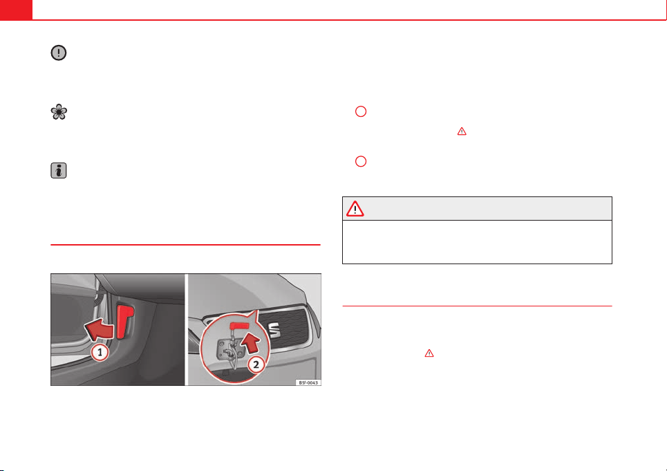
210 Checking and refilling levels
CAUTION
When changing or topping up service fluids, make absolutely certain that
you fill the fluids into the correct reservoirs. Using the wrong fluids could
cause serious malfunctions and engine damage!
For the sake of the environment
Inspect the ground underneath your vehicle regularly so that any leaks are
detected at an early stage. If you find spots of oil or other fluids, have your
vehicle inspected at the workshop.
Note
On right-hand drive vehicles* some of the containers/reservoirs mentioned
below are located on the other side of the engine compartment.
Opening the bonnet
The bonnet is released from inside the vehicle.
Fig. 107 Release lever in driver footwell and cam below the bonnet
Check that the windscreen wiper arms are not unfolded. Otherwise
the paint may be damaged.
The bonnet can only be unlocked when the driver door is open.
– Pull the lever under the dash panel in the direction of the arrow
1
⇒ Fig. 107.
– Lift the bonnet slightly ⇒
.
– Press the release catch under the bonnet upwards ⇒ Fig. 107
2
. This will release the arrester hook under the bonnet.
– Open the bonnet.
WARNING
Never open the bonnet if you see steam or drips of coolant being re-
leased from the engine compartment. Failure to comply could result in
burns. Wait until no steam or coolant can be seen before opening the
bonnet.
Closing the bonnet
– Press the bonnet down until it locks into place.
– Make sure that the bonnet catches onto its clasp. Do not press
down too hard ⇒
.
211Checking and refilling levels
WARNING
● For safety reasons the bonnet must always be completely closed
when the vehicle is moving. Therefore, after closing the bonnet, always
check that the locking element is properly engaged. This is the case if
the bonnet is flush with the adjacent body panels.
● Should you notice that the bonnet is not safely secured when the ve-
hicle is moving, stop the vehicle immediately and close the bonnet. Fail-
ure to do so could result in an accident.
Engine oil
General notes
The engine comes with a special, multi-grade oil that can be used all year
round.
Because the use of high-quality oil is essential for the correct operation of
the engine and its long useful life, when topping up or changing oil, use on-
ly those oils that comply with VW standards.
The specifications (VW standards) set out in the following page should ap-
pear on the container of the service oil; when the container displays the
specific standards for petrol and diesel engines together, it means that the
oil can be used for both types of engines.
We recommend that the oil change, indicated in the Maintenance Pro-
gramme, be performed by a Technical Service or a specialised workshop.
The correct oil specifications for your engine are listed in ⇒ page 212, Oil
properties.
Service intervals
Service intervals can be flexible (LongLife service) or fixed (dependent on
time/distance travelled).
If the PR code that appears on the back of the “Maintenance Programme”
booklet is PR QI6, this means that your vehicle has the LongLife service pro-
grammed. If it lists the codes QI1, QI2, QI3, QI4 or QI7, the interval service
is dependent on time/distance travelled.
Flexible service intervals (LongLife service intervals*)
Special oils and processes have been developed which, depending on the
characteristics and individual driving profiles, enable the extension of the
oil change service (LongLife service intervals).
Because this oil is essential for extending the service intervals, it must only
be used observing the following indications:
● Avoid mixing it with oil for fixed service intervals.
● Only in exceptional circumstances, if the engine oil level is too low
⇒ page 212 and LongLife oil is not available, it is permitted to top up
(once) with oil for fixed service intervals ⇒ page 212 (up to a maximum of
0.5 litres).
Fixed service intervals*
If your vehicle does not have the “LongLife service interval” or it has been
disabled (by request), you may use oils for fixed service intervals, which al-
so appear in ⇒ page 212, Oil properties. In this case, your vehicle must be
serviced after a fixed interval of 1 year/15 000 km (10 000 miles)(whatever
comes first) ⇒ Booklet Maintenance Programme.
● In exceptional circumstances, if the engine oil level is too low
⇒ page 212 and you cannot obtain the oil specified for your vehicle, you
can put in a small quantity of oil conforming to the specification ACEA A2 or
ACEA A3 (petrol engines) or ACEA B3 or ACEA B4 (diesel engines) (up to 0.5
l).
Safety First Operating instructions Practical Tips Technical specifications
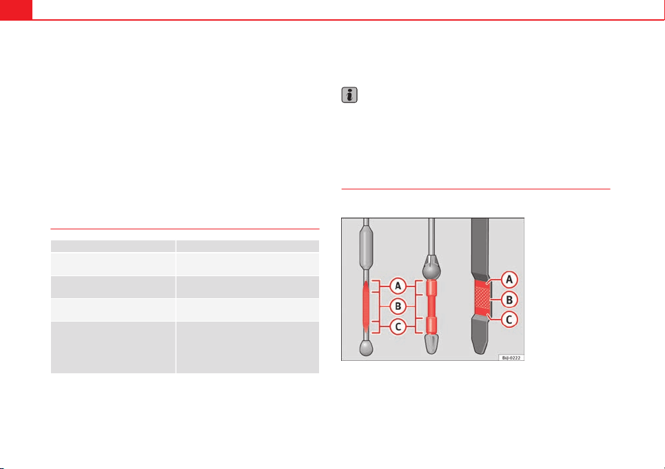
212 Checking and refilling levels
Vehicles with diesel particulate filter*
The “Maintenance Programme” states whether your vehicle is fitted with a
diesel particulate filter.
Only VW 507 00 engine oil, with reduced ash formation, may be used in die-
sel engines equipped with particulate filter. Using other types of oil will
cause a higher soot concentration and reduce the life of the DPF. Therefore:
● Avoid mixing this oil with other engine oils.
● Only in exceptional circumstances, if the engine oil level is too low
⇒ page 212 and you cannot obtain the oil specified for your vehicle, you
can use a small quantity of oil (once) conforming to the VW 506 00,
VW 506 01, VW 505 00, VW 505 01 or ACEA B3/ACEA B4 specification. (up
to 0.5 l).
Oil properties
Engine type Specification
Petrol without flexible service in-
terval
VW 502 00/VW 504 00
Petrol with flexible service inter-
val (LongLife)
VW 504 00
Diesel. Engines without Particu-
late filter (DPF)
VW 505 01/VW 506 01/VW 507 00
Diesel. Particulate Filter Engines
(DPF).
With or without flexible service in-
terval (with and without Long-
life)
a)
VW 507 00
a)
Only use recommended oils, otherwise you may damage the engine.
Engine oil additives
No type of additive should be mixed with the engine oil. The deterioration
caused by these additives is not covered by the warranty.
Note
Before a long trip, we recommend finding an engine oil that conforms to the
corresponding VW specifications and recommend keeping it in the vehicle.
This way, the correct engine oil will always be available for a top-up if nee-
ded.
Checking engine oil level
The engine oil dipstick indicates the level of the oil.
Fig. 108 Engine oil dip-
stick
Checking oil level
– Park the vehicle in a horizontal position.
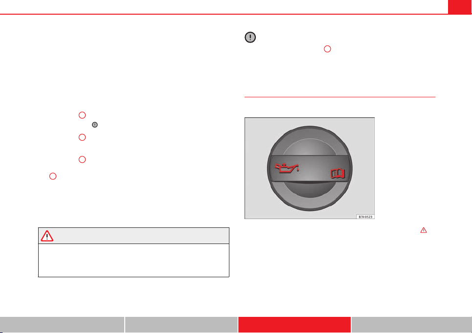
213Checking and refilling levels
– Briefly run the engine at idle speed until the operating tempera-
ture is reached and then stop.
– Wait two minutes.
– Pull out the dipstick. Wipe the dipstick with a clean cloth and
insert it again, pushing it in as far as it will go.
– Then pull it out once more and check the oil level ⇒ Fig. 108.
Top up with engine oil if necessary.
Oil level in area
A
Do not add oil ⇒ .
Oil level in area
B
You can add oil, but keep the level in this zone.
Oil level in area
C
Oil must be added. Afterwards, the oil level should be in the lined area
B
.
Depending on how you drive and the conditions in which the vehicle is
used, oil consumption can be up to 0.5 l/1000 km. Oil consumption is likely
to be higher for the first 5000 km. For this reason the engine oil level must
be checked at regular intervals, preferably when filling the tank and before
a journey.
WARNING
Any work carried out in the engine compartment or on the engine must
be carried out cautiously.
● When working in the engine compartment, always observe the safety
warnings ⇒ page 209.
–
–
–
CAUTION
If the oil level is above the area
A
do not start the engine. This could result
in damage to the engine and catalytic converter. Contact a Technical Serv-
ice.
Topping up engine oil
Top up gradually with small quantities of engine oil.
Fig. 109 In the engine
compartment: Engine oil
filler cap
Before opening the bonnet, read and observe the warnings
⇒
in
Working on components in the engine compartment on page 209.
– Unscrew cap from engine oil filler opening
⇒
Fig. 109.
– Top-up oil in small amounts, using the correct oil.
– To avoid over-filling with engine oil, you should top-up using
small quantities, wait a while and check the oil level before
adding any more oil.
Safety First Operating instructions Practical Tips Technical specifications
214 Checking and refilling levels
– As soon as the oil level is in area
B
, carefully close the cap.
The position of the oil filler opening is shown in the corresponding engine
compartment illustration ⇒ page 267.
Engine oil specification ⇒ page 211.
WARNING
Oil is highly inflammable! Ensure that no oil comes into contact with hot
engine components when topping up.
CAUTION
If the oil level is above the area
A
do not start the engine. This could result
in damage to the engine and catalytic converter. Contact a specialised work-
shop.
For the sake of the environment
The oil level must never be above area
A
. Otherwise oil can be drawn in
through the crankcase breather and escape into the atmosphere via the ex-
haust system.
Changing engine oil
The engine oil must be changed at the intervals given in the
service schedule.
We recommend that you have the engine oil changed by a Technical Serv-
ice.
The oil change intervals are shown in the Maintenance Programme.
WARNING
Only change the engine oil yourself if you have the specialist knowledge
required!
● Before opening the bonnet, read and observe the warnings
⇒ page 209.
● Wait for the engine to cool down. Hot oil may cause burn injuries.
● Wear eye protection to avoid injuries, such as acid burns, caused by
splashes of oil.
● When removing the oil drain plug with your fingers, keep your arm
horizontal to help prevent oil from running down your arm.
● Wash your skin thoroughly if it comes into contact with engine oil.
● Engine oil is poisonous! Used oil must be stored in a safe place out of
the reach of children.
CAUTION
No additives should be used with engine oil. This could result in engine
damage. Any damage caused by the use of such additives would not be
covered by the factory warranty.
For the sake of the environment
● Because of the disposal problems, the necessary special tools and spe-
cialist knowledge required, we recommend that you have the engine oil and
filter changed by a Technical Service.
● Never pour oil down drains or into the ground.
● Use a suitable container when draining the used oil. It must be large
enough to hold all the engine oil.

215Checking and refilling levels
Cooling system
Engine coolant specifications
The engine cooling system is supplied from the factory with a specially trea-
ted mixture of water and, at least, 40 % of the additive G 13 (TLVW 774 J).
The engine coolant additive is recognisable by its purple colour. This mix-
ture of water and additive gives the necessary frost protection down to
-25°C (-13 F) and protects the light alloy parts of the cooling system against
corrosion. It also prevents scaling and considerably raises the boiling point
of the coolant.
To protect the engine cooling system, the percentage of additive must al-
ways be at least 40 %, even in warm climates where anti-freeze protection is
not required.
If greater frost protection is required in very cold climates, the proportion of
additive can be increased. However, the percentage of additive should not
exceed 60 %, as this would reduce the frost protection and, in turn, de-
crease the cooling capacity.
When the coolant is topped up, use a mixture of distilled water and, at
least, 40 % of the G 13 or G 12 plus-plus (TL-VW 774 G) additive (both are
purple) to obtain an optimum anticorrosion protection ⇒
. The mixture of
G 13 with G 12 plus (TL-VW 774 F), G 12 (red) or G 11 (green-blue) engine
coolants will significantly reduce the anticorrosion protection and should,
therefore be avoided ⇒
.
WARNING
If there is not enough anti-freeze in the coolant system, the engine may
fail leading to serious damage.
● Please make sure that the percentage of additive is correct with re-
spect to the lowest expected ambient temperature in the zone in which
the vehicle is to be used.
● When the outside temperature is very low, the coolant could freeze
and the vehicle would be immobilised. In this case, the heating would
not work either and inadequately dressed passengers could die of cold.
CAUTION
The original additives should never be mixed with coolants which are not
approved by SEAT. Otherwise, you run the risk of causing severe damage to
the engine and the engine cooling system.
● If the fluid in the expansion tank is not purple but is, for example,
brown, this indicates that the G 13 additive has been mixed with an inade-
quate coolant. The coolant must be changed as soon as possible if this is
the case! This could result in serious faults and engine damage.
For the sake of the environment
Coolants and additives can contaminate the environment. If any fluids are
spilled, they should be collected and correctly disposed of, with respect to
the environment.
Safety First Operating instructions Practical Tips Technical specifications
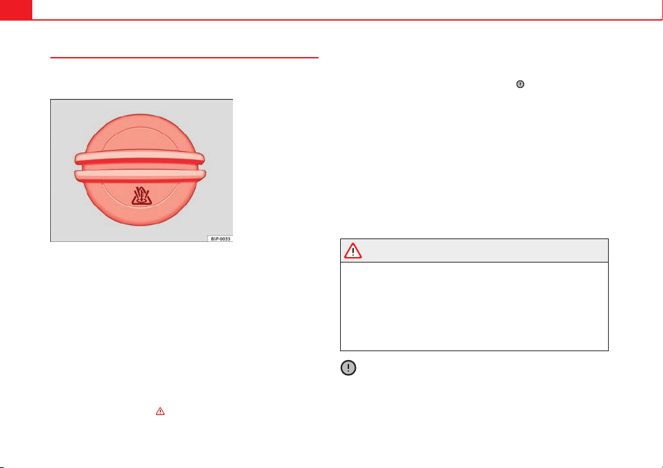
216 Checking and refilling levels
Topping up coolant
Top up coolant when the level is below the MIN (minimum)
mark.
Fig. 110 Engine com-
partment: Coolant expan-
sion tank cap
Checking coolant level
– Park the vehicle in a horizontal position.
– Switch the ignition off
– Read off the coolant level on coolant expansion tank. When the
engine is cold, the coolant level should be between the marks.
When the engine is hot, it may be slightly above the upper
mark.
Topping up coolant
– Wait for the engine to cool down.
– Cover the coolant expansion tank cap with a cloth and carefully
unscrew it to the left ⇒
.
– Top up the coolant only if there is still coolant in the expansion
tank, otherwise you could damage the engine. If there is no
coolant in the expansion tank, do not continue driving. You
should obtain professional assistance ⇒
.
– If there is still some coolant in the expansion tank, top up to the
upper mark.
– Top up with coolant to the upper mark until the level becomes
stable.
– Screw the cap back on correctly.
Any loss of coolant fluid normally indicates a leak in the cooling system.
Take the vehicle straight to a specialised workshop to have the cooling sys-
tem examined. If there are no leaks in the engine cooling system, a loss of
coolant can only occur if the coolant boils and is forced out of the system as
a result of overheating.
WARNING
● The cooling system is under pressure. Do not unscrew the cap on the
coolant expansion tank when the engine is hot: risk of burns!
● The antifreeze and coolant fluid can be a health hazard. Therefore,
the antifreeze should be stored in the original container in a safe place
out of reach of children. Failure to comply could result in poisoning.
● If working inside the engine compartment, remember that, even when
the ignition is switched off, the radiator fan may start up automatically,
and therefore there is a risk of injury.
CAUTION
Do not top up the expansion tank with coolant fluid if it is empty! Air could
enter the cooling system. In this case, stop driving. Seek specialist assis-
tance. Otherwise, there is a risk of engine damage.
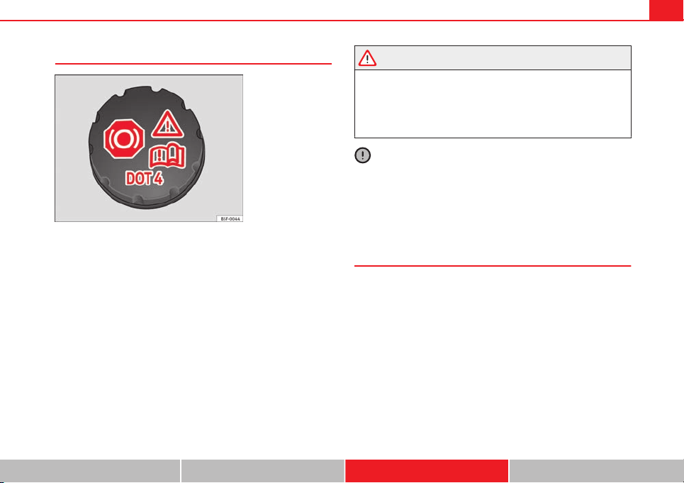
217Checking and refilling levels
Brake fluid
Fig. 111 Engine com-
partment: brake fluid res-
ervoir, lid
Checking the brake fluid level
The brake fluid level must be between the MIN and MAX markings.
However, if the brake fluid level goes down noticeably in a short time, or
drops below the MIN mark, there may be a leak in the brake system. Seek
specialist assistance. A warning light on the instrument panel display moni-
tors the brake fluid level
⇒
page 69.
In right-hand drive vehicles the brake fluid reservoir is on the other side of
the engine compartment.
Changing brake fluid
The regular intervals at which the brake fluid should be replaced are listed
in the Service Plan. We recommend you have the brake fluid replaced at a
SEAT Official Service, during an Inspection Service.
WARNING
● Brake fluid should be stored in the closed original container in a safe
place out of reach of children. Risk of poisoning!
● If the brake fluid is left in the system for too long and the brakes are
subjected to heavy use, vapour bubbles may form in the brake system.
This would seriously affect the efficiency of the brakes and the safety of
the vehicle. This may cause an accident.
CAUTION
Brake fluid should not come into contact with the vehicle paintwork, as it is
abrasive.
Battery
General information
The battery is located in the engine compartment and is almost mainte-
nance-free. It is checked as part of the Inspection Service. Nevertheless,
check the terminals are clean and have the correct tightening torque, espe-
cially in summer and winter.
Disconnecting the battery
The battery should only be disconnected in exceptional cases. When the
battery is disconnected, some of the vehicles functions are "lost" (
⇒
table
on page 218). These functions will require resetting after the battery is re-
connected.
Deactivate the anti-theft alarm* before you disconnect the battery Other-
wise the alarm will be triggered.
Safety First Operating instructions Practical Tips Technical specifications

218 Checking and refilling levels
Function Reprogramming
One-touch function of the electric
windows
⇒ page 101, One-touch opening and
closing*
Remote control key
If the vehicle does not respond to the
key, they should be synchronised
⇒ page 90
Digital clock ⇒ page 63
ESC warning lamp
After driving for a few metres, the
warning lamp goes out again.
If the vehicle is not used for long periods
The vehicle has a system for monitoring the current consumption when the
engine is left unused for long periods of time ⇒ page 187. Some functions,
such as the interior lights, or the remote door opening, may be temporarily
disabled to prevent the battery from running flat. These functions will come
back on as soon as the ignition is switched on and the engine started.
Winter conditions
During the winter, the starting power may be reduced, and if necessary, the
battery should be charged ⇒
in Important safety warnings for handling a
vehicle battery on page 218
Important safety warnings for handling a vehicle battery
All work on batteries requires specialist knowledge. Please refer to a SEAT
Official Service or a workshop specialising in batteries: risk of burns or ex-
ploding battery!
The battery must not be opened. Never try to change the fluid level of the
battery. Explosive gas is released from the battery that could cause an ex-
plosion.
Wear eye protection.
Battery acid is very corrosive and caustic. Wear protective gloves
and eye protection. In the event of electrolyte splashes, rinse off
with plenty of water.
Fires, sparks, open flames and smoking are prohibited.
The battery should only be charged in a well-ventilated zone. Risk
of explosion!
Keep children away from acid and batteries!
WARNING
● When repairing or working on the electrical system, proceed as fol-
lows:
● 1. Remove the key from the ignition. The negative cable on the bat-
tery must be disconnected.
● 2. When the repair is finished, reconnect the negative pole of the bat-
tery.
● Switch off all electrical consumers before reconnecting the battery.
Reconnect first the positive cable and then the negative cable. Never re-
verse the polarity of the connections. This could cause an electrical fire.
● Ensure that the vent hose is always connected to the battery.
● Never use damaged batteries. This could cause an explosion! Replace
a damaged battery immediately.
CAUTION
● Never disconnect the battery if the ignition is switched on or if the en-
gine is running. This could damage the electrical system or electronic com-
ponents.
219Checking and refilling levels
Charging the battery
Terminals for charging the battery are fitted in the engine
compartment.
– Note the warnings ⇒
in Important safety warnings for han-
dling a vehicle battery on page 218 and ⇒
.
– Switch off all electrical equipment. Remove the ignition key.
– Raise the bonnet ⇒ page 210.
– Open the battery cover.
– Connect the charger clamps as described to the positive pole of
the battery (+) and, exclusively to an earth on the bodywork
(–).
– Only use a charger which is compatible for use with 12 V nomi-
nal voltage batteries. The charge must not exceed a voltage of
15 V.
– Now connect the battery charger to the power socket and switch
on.
– After charging the battery: switch off the battery charger and
disconnect the power socket cable.
– Finally disconnect the charger cables from the battery.
– Replace the battery cover correctly.
– Close the bonnet ⇒ page 210.
Important: Before you charge the battery make sure you read the manufac-
turer's instructions for using the battery charger.
WARNING
Never charge a battery that has frozen: replace battery! Failure to do so
may lead to an explosion.
Note
Use only the terminals in the engine compartment to charge the battery.
Replacing the battery
The new battery should have the same specifications (am-
perage, load and voltage) as the used battery.
Your vehicle is equipped with an intelligent power management system to
control the distribution of electrical energy
⇒
page 187. The power manage-
ment function ensures that the battery is charged much more efficiently
than on vehicles without a power management system. To maintain this
function after replacing the battery, we recommend that the replacement
battery used is of the same make and type as the original fitted battery. To
make proper use of the power management function after the battery has
been changed, have the battery coded to the power management mode at a
specialised workshop.
CAUTION
● Some vehicles, for example those with the Start-Stop system* are fitted
with a special battery (AGM-type or EFB-type battery). If any other type of
battery is fitted, the Start-Stop function may be considerably reduced and
the vehicle may not stop on repeated occasions.
● Make sure that the vent hose is always attached to the original opening
on the side of the battery. Gases or battery acid can otherwise escape and
possibly cause damage.
● The battery holder and clamps must always be correctly secured.
Safety First Operating instructions Practical Tips Technical specifications
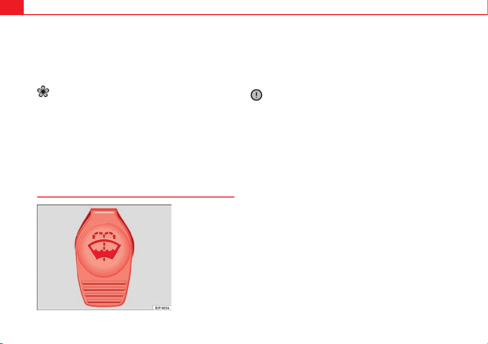
220 Checking and refilling levels
● Before starting any work on the battery, always observe the warnings lis-
ted under ⇒ page 218, Important safety warnings for handling a vehicle
battery.
● Do not forget to replace the battery coverings, where applicable. This
helps to protect against excess temperatures. This in turn extends the vehi-
cle service life.
For the sake of the environment
Batteries contain toxic substances including sulphuric acid and lead. They
must be disposed of appropriately and must not be disposed of with ordi-
nary household waste. Make sure disconnected batteries cannot tip over.
Sulphuric acid could be spilt!
Windscreen washer reservoir and wiper
blades
Windscreen washer
Fig. 112 Engine com-
partment: Windscreen
washer reservoir top
The windscreen washer reservoir contains the cleaning fluid for the wind-
screen, the rear window and the headlight washer system* ⇒ Fig. 112. Res-
ervoir capacity: ⇒ page 276.
To prevent the nozzles from becoming blocked with chalk deposits, fill res-
ervoir with water with a low calcium content (distilled water). Always add
washer fluid to the water (with anti-freeze additive in winter).
CAUTION
● Never put radiator anti-freeze or other additives into the windscreen
washer fluid.
● Never use washer fluid which contains paint thinners or solvents as it
can damage the paintwork.
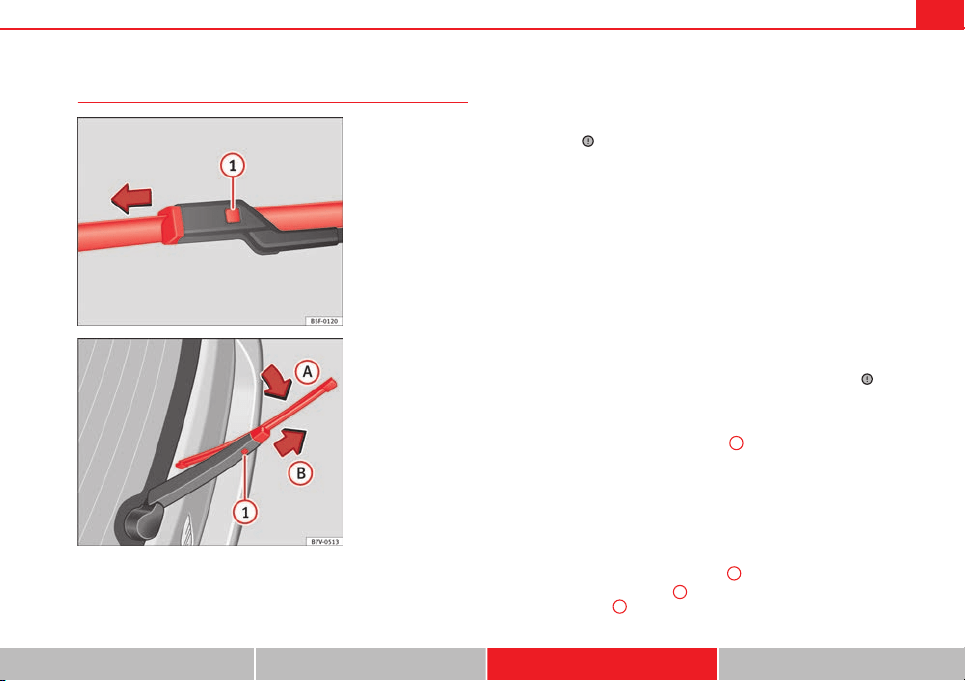
221Checking and refilling levels
Cleaning and changing the wiper blades of the windscreen
and rear window
Fig. 113 Changing the
windscreen wiper blades
Fig. 114 Changing the
rear wiper blade
The windscreen wiper blades are supplied as standard with a layer of graph-
ite. This layer is responsible for ensuring that the wipe is silent. If the graph-
ite layer is damaged, the noise of the water as it is wiped across the wind-
screen will be louder.
Check the condition of the wiper blades regularly. If the wipers scrape
across the glass they should be changed if they are damaged, or cleaned if
they are dirty ⇒
.
Damaged wiper blades should be replaced immediately. Wiper blades are
available from specialised workshops.
Raising/lowering windscreen wiper arms
For windscreen wipers, please note: the wiper should be in service position
before being lowering ⇒ page 119.
When raising or lowering an arm, it should only be held at the blade fasten-
ing point.
Cleaning windscreen wiper blades
● Raising the wiper arms.
● Use a soft cloth to remove dust and dirt from the windscreen wiper
blades.
● If the blades are very dirty, a sponge or damp cloth may be used ⇒
.
Changing the windscreen wiper blades
● Raising/lowering wiper arms
● Hold down the release button ⇒ Fig. 113
1
while gently pulling the
blade in the direction of the arrow.
● Fit a new wiper blade of the same length and design on to the wiper arm
and hook it into place.
● Rest the wiper arms back onto the windscreen.
Changing the rear wiper blade
● Raising/lowering the wiper arm.
● Turn the blade slightly ⇒ Fig. 114 (arrow
A
).
● Hold down the release button
1
while gently pulling the blade in the
direction of the arrow
B
.
Safety First Operating instructions Practical Tips Technical specifications
222 Checking and refilling levels
● Insert a new blade of the same length and type in the rear wiper arm in
the opposite direction to the arrow
B
and hook into place button
1
.
● Replace the wiper arm on the rear window.
WARNING
Worn or dirty wiper blades reduce visibility and increase the risk of acci-
dent and serious injury.
● Always replace damaged or worn blades or blades which do not clean
the windscreen correctly.
CAUTION
● Damaged or dirty windscreen wipers could scratch the glass.
● If products containing solvents, rough sponges or sharp objects are
used to clean the blades, the graphite layer will be damaged.
● Never use fuel, nail varnish remover, paint thinner or similar products to
clean the windows.

223Wheels and tyres
Wheels and tyres
Wheels
General notes
– When driving with new tyres, be especially careful during the
first 500 km (300 miles).
– If you have to drive over a kerb or similar obstacle, drive very
slowly and as near as possible at a right angle to the obstacle.
– Check from time to time if the tyres are damaged (punctures,
cuts, cracks or dents). Remove any foreign objects embedded in
the treads.
– Damaged wheels and tyres must be replaced immediately.
– Keep grease, oil and fuel off the tyres.
– Replace any missing valve caps as soon as possible.
– Mark the wheels before taking them off so that they rotate in
the same direction when put back.
– When removed, the wheels or tyres should be stored in a cool,
dry and preferably dark place.
New tyres
New tyres do not give maximum grip straight away and should therefore be
“run in” by driving carefully and at moderate speeds for about the first 500
km (300 miles). This will also increase the useful life of the tyres.
The tread depth of new tyres may vary, according to the type and make of
tyre and the tread pattern.
Concealed damage
Damage to tyres and rims is often not readily visible. If you notice unusual
vibration or the car pulling to one side, this may indicate that one of the
tyres is damaged. Reduce speed immediately if there is any reason to sus-
pect that damage may have occurred. Inspect the tyres for damage. If no ex-
ternal damage is visible, drive slowly and carefully to the nearest special-
ised workshop and have the car inspected.
Tyres with directional tread pattern
An arrow on the tyre sidewall indicates the direction of rotation on single
drive tyres. Always note the direction of rotation indicated when mounting
the wheel. This guarantees optimum grip and helps to avoid aquaplaning,
excessive noise and wear.
Retrofitting Accessories
If you wish to change or fit wheels, rims or wheel trims, we recommend that
you consult with a SEAT Official Service centre for advice regarding current
techniques.
Useful life of tyres
Correct inflation pressures and sensible driving habits will
increase the useful life of your tyres.
– Check tyre pressure at least once a month, and also prior to any
long trip.
Safety First Operating instructions Practical Tips Technical specifications

224 Wheels and tyres
– The tyre pressure should only be checked when the tyres are
cold. The slightly raised pressures of warm tyres must not be re-
duced.
– Adjust tyre pressure to the load being carried by the vehicle.
– In vehicles with a tyre pressure indicator, save the pressure of
modified tyres ⇒ page 175, ⇒ page 223.
– Avoid fast cornering and hard acceleration.
– Inspect the tyres for irregular wear from time to time.
The useful life of your tyres depends on the following factors:
Tyre pressure
Tyre pressure values are indicated on the inside of the fuel tank flap.
Insufficient or excessive pressure greatly reduces the useful life of the tyres
and adversely affects vehicle performance and ride. Correct inflation pres-
sures are very important, especially at high speeds.
If you want a more comfortable ride, you can inflate tyres to the pressure
corresponding to the normal vehicle load (up to 3 people) if the vehicle is
carrying a normal load. If the vehicle is going to carry the maximum load,
the tyre pressure should be increased to maximum value indicated.
The tyre pressure must be adjusted according to the load the vehicle is car-
rying. We recommend adhering to the tyre pressure specifications for a max-
imum load.
Do not forget the spare wheel when checking the tyre pressures: Keep the
spare wheel inflated to the highest pressure required for the road wheels.
In the case of a minimised temporary spare wheel (125/70 R16 or 125/70
R18) inflate to a pressure of 4.2 bar as indicated on the tyre pressure label
on the fuel tank flap.
Driving style
Fast cornering, heavy acceleration and hard braking (squealing tyres) all in-
crease tyre wear.
Wheel balance
The wheels on new vehicles are balanced. However, certain circumstances
may lead to imbalance (run-out), which is detected as vibrations in the
steering wheel.
Unbalanced wheels should be rebalanced, as they otherwise cause exces-
sive wear on steering, suspension and tyres. A wheel must also be reba-
lanced when a new tyre is fitted or if a tyre is repaired.
Incorrect wheel alignment
Incorrect wheel alignment causes excessive tyre wear, impairing the safety
of the vehicle. If you notice excessive tyre wear, you should check wheel
alignment at a SEAT Official Service.
WARNING
● Always adapt the tyre pressure accordingly when the vehicle load
changes.
● A tyre with low air pressure has to flex a lot more when the vehicle is
heavily loaded or at high speeds, therefore causing overheating to occur.
Under these conditions, the tyre bead may be released or the tyre may
burst. Risk of accident!
For the sake of the environment
Under-inflated tyres will increase fuel consumption.
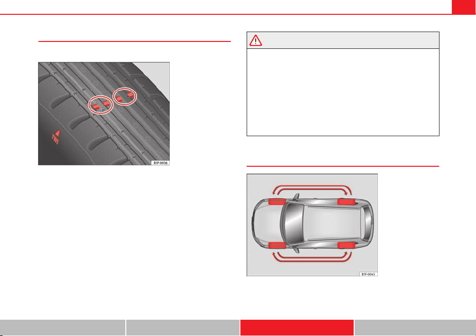
225Wheels and tyres
Indications of wear
Tread wear indicators indicate if a tyre is worn.
Fig. 115 Tyre tread:
tread wear indicators
The original tyres on your vehicle have 1.6 mm high “tread wear indicators”
running across the tread. Depending on the manufacturer, there will be 6 to
8 of them spaced at equal distances around the tyre. Markings on the tyre
sidewall (for instance the letters “TWI” or a triangle) indicate the positions
of the tread wear indicators.
The minimum tread depth required by law is 1.6 mm (measured in the tread
grooves next to the tread wear indicators). (Different figures may apply in
other countries.)
WARNING
The tyres must be replaced at the latest when the tread is worn down to
the tread wear indicators. Failure to do so could result in an accident.
● Especially in difficult driving conditions such as wet or icy roads, it is
important that the tyres have sufficient tread depth. The tread depth
should same on the tyres of both the front and the rear axles.
● The decrease in driving safety due to insufficient tread depth is par-
ticularly evident in vehicle handling, when there is a risk of aquaplaning
in deep puddles of water and when driving through corners. Braking is
also adversely affected.
● The speed has to be adapted accordingly, otherwise there is a risk of
losing control over the vehicle.
Changing wheels
Fig. 116 Changing
wheels around
Safety First Operating instructions Practical Tips Technical specifications
226 Wheels and tyres
To ensure that the wear is equal on all tyres the wheels should be changed
round from time to time according to the system ⇒ Fig. 116. The useful life
of all the tyres will then be about the same time.
Replacing wheels and tyres
It is important to use the correct wheels and tyres when re-
placement is necessary.
– All four wheels must be fitted with tyres of the same type, size
(rolling circumference) and preferably the same tread pattern.
– Tyres should be replaced at least in pairs and not individually
(i.e. both front tyres or both rear tyres together).
– Do not use tyres whose effective size exceeds the dimensions
of the factory-approved makes of tyre.
– If you wish to fit the vehicle with rims or tyres that are different
to those installed in manufacture, it is advisable to consult a
SEAT Official Service before purchasing them.
The tyres and wheel rims are an essential part of the vehicle's design. The
tyres and rims approved by SEAT are specially matched to the characteris-
tics of the vehicle and make a major contribution to good roadholding and
safe handling ⇒
.
The sizes of the rims and tyres approved for your vehicle are listed in the
vehicle documentation (e.g. EC Certificate of Conformity or COC docu-
ment
1)
). The vehicle documentation varies depending on the country of resi-
dence.
A knowledge of tyre designations makes it easier to choose the correct
tyres. The following wording can be read on the sides of the tyre:
205/55 R 16 91 V
This contains the following information:
205 Tyre width in mm
55 Height/width ratio in %
R Tyre construction: Radial
16 Rim diameter in inches
91 Load rating code
W Speed index
The manufacturing date is also indicated on the tyre sidewall (possibly only
on the inner side of the wheel):
DOT ... 2212 ...
means that the tyre was produced in the 22nd week of 2012.
Please note that with some types of tyre, the actual tyre size can differ from
the nominal size marked on the tyre (for instance 205/55 R 16 91 W), and
there may be significant differences in the contours of the tyres, even
though the tyres are marked with the same nominal size designation.
When replacing the tyres, it is therefore important to make sure that the
actual size of the new tyres does not exceed the dimensions of the factory-
approved makes of tyre.
Failure to observe this requirement can affect the clearance needed for the
tyres. This could result in contact between the tyres and suspension com-
ponents or bodywork causing damage. The brake lines could also be dam-
aged and vehicle safety could be severely impaired ⇒
.
1)
COC = certificate of conformity
227Wheels and tyres
If you use tyres that are approved by SEAT you can be sure that the actual
tyre dimensions will be correct for your vehicle. If you decide to fit a differ-
ent type of tyre, you must obtain the appropriate manufacturer's certificate
from the tyre retailer to confirm that the tyres are suitable for your vehicle.
Keep this certificate in a safe place.
Your SEAT Official Service will be able to advise you on which tyres may be
fitted to your vehicle.
It is best to have all servicing of wheels and tyres performed by a special-
ised workshop. They are familiar with the procedure and have the necessary
special tools and spare parts as well as the proper facilities for disposing of
the old tyres.
WARNING
● It is very important to ensure that the tyres you have chosen have ad-
equate clearance. When selecting replacement tyres, do not rely entirely
on the nominal tyre size marked on the tyre; with some makes of tyre the
effective tyre size can differ significantly from the nominal dimensions,
even though the tyres have the same size designation. Inadequate tyre
clearance can result in damage to the tyres or the vehicle, causing a seri-
ous safety risk. It may also invalidate the vehicle's registration for use on
public roads.
● Avoid running the vehicle on tyres that are more than 6 years old. If
you have no alternative, you should drive slowly and with extra care at all
times.
● If wheel trims are fitted after the car is purchased, ensure that there
is an adequate flow of air for cooling the brake system.
For the sake of the environment
Old tyres must be disposed of according to the laws in the country con-
cerned.
Note
● Never mount used tyres if you are not sure of their “previous history”.
● For technical reasons, it is not generally possible to use the wheels from
other vehicles. In some cases, this may also be true for the same model of
wheel.
Wheel bolts
The wheel bolts are designed to suit the rims on your car.
The wheel bolts are matched to the rims. When installing different wheels
(for instance alloy wheels or wheels with winter tyres) it is important to use
the correct wheel bolts with the right length and correctly shaped bolt
heads. This ensures that wheels are fitted securely and that the brake sys-
tem functions correctly.
The wheel bolts must be clean and turn easily.
A special adapter is required to turn the anti-theft wheel bolts*
⇒ page 237.
Winter tyres
Winter tyres will improve the vehicles handling on snow and
ice.
– Winter tyres must be fitted on all four wheels.
– Only use winter tyres that are approved for your vehicle.
– Please note that the maximum permissible speed for winter
tyres may be lower than for summer tyres.
Safety First Operating instructions Practical Tips Technical specifications
228 Wheels and tyres
– Also note that winter tyres are no longer effective when the
tread is worn down.
– After fitting the wheels you must always check the tyre pres-
sures. The correct tyre pressures are listed on the sticker on the
inside of the fuel tank flap ⇒ page 223.
In winter road conditions winter tyres will considerably improve vehicle han-
dling. The design of summer tyres (width, rubber compound, tread pattern)
gives less grip on ice and snow. This applies particularly to vehicles equip-
ped with wide section tyres or high speed tyres (code letters H, V or Y on
the sidewall).
Only use winter tyres of the correct type approved for your vehicle. The sizes
of the winter tyres approved for your vehicle are listed in the vehicle docu-
mentation (e.g. EC Certificate of Conformity or COC document
1)
). The vehi-
cle documentation varies depending on the country of residence. See also
⇒ page 226.
Winter tyres lose a great deal of their properties when the tread is worn
down to a depth of 4 mm.
The performance of winter tyres is also severely impaired by ageing, even if
the tread is still much deeper than 4 mm.
Winter tyres are subject to the following maximum speed limits according to
speed rating code letter: ⇒
Speed rating code
letter ⇒ page 226
Maximum speed limit
Q 160 km/h (140 mph)
S 180 km/h (140 mph)
T 190 km/h (140 mph)
Speed rating code
letter ⇒ page 226
Maximum speed limit
H 210 km/h (140 mph)
V 240 km/h (150 mph)
(note restrictions)
Vehicles capable of exceeding these speeds must have an appropriate
sticker attached so that it is visible to the driver. Suitable stickers are availa-
ble from the SEAT Official Service and specialised workshop. Please note
regulations to this effect in your country.
“All-weather” tyres can also be used instead of winter tyres.
Using winter tyres with V-rating
Please note that the generally applicable 240 km/h (150 mph) speed rating
for winter tyres with the letter V is subject to technical restrictions; the max-
imum permissible speed for your vehicle may be significantly lower. The
maximum speed limit for tyres with a V-rating depends directly on the maxi-
mum axle weights for your car and on the listed weight rating of the tyres
being used.
It is best to contact a SEAT Official Service to check the maximum speed
which is permissible for the V-rated tyres fitted on your car on the basis of
this information.
WARNING
Exceeding the maximum speed permitted for the winter tyres fitted on
your car can cause tyre failure, resulting in a loss of control of the vehicle
– risk of accident.
1)
COC = certificate of conformity
229Wheels and tyres
For the sake of the environment
Summer tyres should be fitted again as soon as possible; they give better
handling on roads which are free of snow and ice. Summer tyres perform
with less rolling noise, tyre wear and – most important – reduce fuel con-
sumption.
Snow chains
Snow chains will improve vehicle handling on snow-covered
roads.
– Snow chains can be used on the front wheels only.
– Check that the snow chains are correctly seated after driving for
a few yards. Always take the manufacturer assembly instruc-
tions into account.
– Keep your speed below 50 km/h (30 mph).
– If there is a danger of being trapped despite having mounted
the chains, it is best to disable the driving wheels (ASR) in the
ESC ⇒ page 184, Switching on/off the ESC and ASR.
Snow chains will improve braking ability as well as traction in winter condi-
tions.
For technical reasons snow chains may only be used with the following
wheel rim/tyre combination.
195/65 R15 Chains with links of maximum 15 mm
205/55 R16 Chains with links of maximum 15 mm
225/45 R17 Chains with links of maximum 9 mm
225/40 R18 Chains with links of maximum 9 mm
Only use snow chains with fine-pitch links. The links must not protrude
more than 13.5 mm from the tyres (including tensioner).
Remove wheel covers and trim rings before fitting snow chains.
Remove the chains when roads are free of snow. Otherwise they will impair
handling, damage the tyres and wear out very quickly.
Safety First Operating instructions Practical Tips Technical specifications

230 Accessories and modifications to the vehicle
Accessories and modifications to the vehicle
Accessories, replacement parts and repairs
Always ask your dealer or specialist retailer for advice be-
fore purchasing accessories and replacement parts.
Your vehicle is designed to offer a high standard of active and passive safe-
ty. For this reason, we recommend that you ask a SEAT Official Service for
advice before fitting accessories or replacement parts. Your SEAT Official
Service has the latest information from the manufacturer and can recom-
mend accessories and replacement parts which are suitable for your re-
quirements. They can also answer any questions you might have regarding
official regulations.
We recommend you to use only SEAT accessories and Genuine SEAT parts
®
.
SEAT has tested these parts and accessories for suitability, reliability and
safety. SEAT Official Services have the necessary experience and facilities to
ensure that the parts are installed correctly and professionally.
Any retro-fitted equipment which has a direct effect on the vehicle and/or
the way it is driven (e.g. cruise control system or electronically-controlled
suspension) must be approved for use in your vehicle and bear the e mark
(the European Union's authorisation symbol).
If any additional electrical components are fitted which do not serve to con-
trol the vehicle itself (for instance a refrigerator box, laptop or ventilator fan,
etc.), these must bear the mark (manufacturer conformity declaration in
the European Union).
WARNING
Accessories, for example telephone holders or cup holders, should never
be fitted on the covers, or within the working range of the airbags. Other-
wise, there is a danger of injury if the airbag is triggered in an accident.
Technical modifications
Modifications must always be carried out according to our
specifications.
Unauthorised modifications to the electronic components, software, wiring
or data transfer in the vehicle may cause malfunctioning. Due to the way the
electronic components are linked together in networks, other indirect sys-
tems may be affected by the faults. This can seriously impair safety, lead to
excessive wear of components, and also invalidate your vehicle registration
documents.
You will appreciate that your SEAT dealership cannot be held liable for any
damage caused by modifications and/or work performed incorrectly.
We recommend that all work should be performed by a SEAT Official Service
using Genuine SEAT parts
®
.
WARNING
Incorrectly performed modifications or other work on your vehicle can
lead to malfunctions and cause accidents.
Radio transmitters and business equipment
Radio transmitters (fixed installation)
Any retrofit installations of radio transmitters in the vehicle require prior ap-
proval. SEAT generally authorises in-vehicle installations of approved types
of radio transmitters provided that:
231Accessories and modifications to the vehicle
● the aerial is installed correctly.
● the aerial is installed on the exterior of the vehicle (and shielded cables
are used together with non-reflective aerial trimming).
● the effective transmitting power does not exceed 10 Watts at the aerial
base.
A SEAT Official Service and specialised workshop will be able to inform you
about options for installing and operating radio transmitters with a higher
transmitting power.
Mobile radio transmitters
Commercial mobile telephones or radio equipment might interfere with the
electronics of your vehicle and cause malfunctions. This may be due to:
● no external aerial
● external aerial incorrectly installed
● transmitting power more than 10 W
You must, therefore, do not operate portable mobile telephones or radio
equipment inside the vehicle without a properly installed external aerial
⇒
.
Please note also that the maximum range of the equipment can only be ach-
ieved with an external aerial.
Business equipment
Retrofit installation of business or private equipment in the vehicle is per-
mitted, provided the equipment cannot interfere with the driver's immedi-
ate control of the vehicle and that any such equipment carries the mark.
Any retrofit equipment that could influence the driver's control of the vehi-
cle must have a type approval for your vehicle and must carry the e mark.
WARNING
Mobile telephones or radio equipment which is operated inside the vehi-
cle without a properly installed external aerial can create excessive mag-
netic fields that could cause a health hazard.
Note
● The posterior fitting of electric and electronic equipment in this vehicle
affects its licence type and could lead to the withdrawal of the vehicle regis-
tration document under certain circumstances.
● Please use the mobile telephone/radio operating instructions.
Safety First Operating instructions Practical Tips Technical specifications
232 Emergencies
Emergencies
General information
– If you have a flat tyre or puncture, park the car as far away from
the flow of traffic as possible in a safe place. If you have a punc-
ture, stop the vehicle on a horizontal surface. If you are on a
slope, take extra care.
– Apply the handbrake.
– Switch on the hazard warning lights.
– Always wear a reflective vest ⇒ page 232.
– Set up the warning triangle.
– All vehicle occupants should leave the car. They should wait in
a safe place (for instance behind the roadside crash barrier).
WARNING
Always observe the above steps and protect yourself and other road
users.
Equipment
Reflective vests
Wearing a reflective vest makes you more visible to other road
users.
Note
● Always wear a reflective vest when you get out of the vehicle in moving
traffic (for example, in the event of breakdown or to load/unload the vehi-
cle).
● Observe the applicable legislation for each country.
Vehicle tools/Tyre repair kit/Compressor*
The vehicle tools, the tyre repair kit and the compressor* are stor-
ed under the floor panel in the luggage compartment.
To access the vehicle tools:
– Lift up the floor panel by the plastic handle until it is fastened to
the tabs on both sides.
Depending on the vehicle equipment, you will find the tyre repair set and
the compressor* under the floor panel cover.
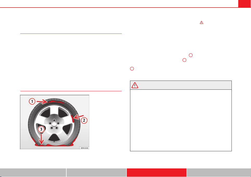
233Emergencies
Tyre repair kit
What to do first
– Please observe the important safety notes ⇒ page 232.
– Apply the handbrake.
– Manual gearbox: Select first gear.
– Automatic gearbox: Move the selector lever to P.
– Check whether a repair is possible using the tyre repair kit
⇒ page 233.
Using the tyre repair kit
Fig. 117 Tyre: irrepara-
ble damage
The tyre repair kit is designed to repair your tyre provisionally only. The dam-
aged tyre should be replaced as soon as possible ⇒
.
If the tyre has been damaged by a nail, for example, remove the nail from
the tyre.
The tyre repair kit can be used at outside temperatures of up to -20 °C
(-4 °F).
The tyre repair kit must NOT be used:
● on cuts and punctures larger than 4 mm
1
⇒ Fig. 117
● If the wheel rim has been damaged
2
● if you have been driving with very low pressure or a completely flat tyre
3
.
If necessary, request assistance from specialised personnel.
WARNING
● Remember that the tyre repair kit cannot always be used, and that it
only serves to provide a provisional repair.
● Do not allow the sealing product to come into contact with your eyes,
skin or clothing.
● If you do come into contact with the sealing product immediately
rinse the eyes or skin affected with clean water.
● Do not inhale vapours.
● If any of the sealing product is accidentally ingested, immediately
rinse the mouth thoroughly and drink lots of water. Do not induce vomit-
ing. Seek medical advice immediately.
● Change clothing immediately if it becomes soiled with the sealing
product.
● If any allergic reactions should occur get medical help immediately.
● Keep the sealing product away from children.
Safety First Operating instructions Practical Tips Technical specifications
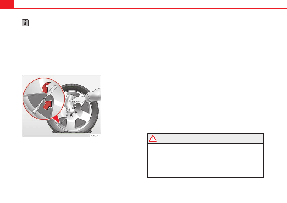
234 Emergencies
Note
● If sealing product should leak out, leave it to dry. This way you can pull it
off like a piece of foil.
● Observe the expiry date stated on the sealing compound can. Have the
sealing compound changed by a specialised workshop or SEAT Service.
● Please observe legal requirements when doing so.
Repairing tyres
Fig. 118 Tyre: top up
Important: have the tyre repair kit ready
⇒
page 232.
Filling the tyre
– Before filling the tyre, shake the bottle of sealing product thor-
oughly.
– Screw the enclosed filling hose onto the sealant can as far as it
will go. This will pierce the foil sealing on the can.
– Take the valve cap off the tyre valve and use a screwdriver
⇒ Fig. 118 to unscrew the valve insert.
– Place the valve insert onto a clean surface.
– Remove the sealing plug from the filling hose and insert the
hose into the tyre valve.
– Hold the bottle upside down and insert the contents in the tyre
until the bottle is empty.
– Then disconnect the hose and screw the valve insert back onto
the tyre valve.
Inflating the tyre
– Screw the compressor filling hose (tyre repair kit) onto the tyre
valve and plug the connector into the 12V connection.
– Pump the tyre up to 2.0 to 2.5 bar and monitor the pressure
shown on the pressure gauge.
– If the tyre does not reach this pressure, move the car forwards
or backwards 10 metres to allow the sealing compound to
spread all around the tyre.
WARNING
● Please observe the manufacturer's safety notes on the compressor
and the instructions supplied with the tyre sealant can.
● If, after six minutes of trying to inflate the tyre, it is not possible get
up to a pressure of 2.0 bar, this indicates that the tyre is too severely
damaged for repair with the kit. Do not carry on driving!
● If the tyre cannot be repaired with the sealing compound, seek pro-
fessional assistance.
235Emergencies
Note
Do not use the compressor for longer than 6 minutes at a time, as it could
overheat. Once it has cooled down, the compressor may be used again.
After changing a wheel
– Attach the "max. 80 km/h (50 mph)" adhesive label from the
tyre repair kit on the instrument panel, clearly within view of the
driver.
– Stop the vehicle after 10 minutes driving and check the tyre
pressure.
– If tyre pressure is less than 1.3 bar, the tyre is too badly dam-
aged. Do not carry on driving!
WARNING
After repairing a tyre please note the following points:
● Do not drive faster than 80 km/h (50 mph).
● Avoid heavy acceleration, hard braking and fast cornering.
● Vehicle handling could be impaired.
● If the tyre is very damaged, seek professional assistance.
For the sake of the environment
You can dispose of the used bottle of sealing compound at a SEAT Official
Service.
Note
After repairing a tyre, remember to purchase a new bottle of sealing com-
pound from a SEAT Official Service or a specialised workshop.
Changing a wheel
What to do first
Before changing the wheel, the following preliminary steps
are required.
– Please observe the important safety notes ⇒ page 232.
– Apply the handbrake.
– Manual gearbox: Select first gear.
– Automatic gearbox: Move the selector lever to P.
– When towing a trailer: Unhitch the trailer from your vehicle.
– Have the vehicle tool kit ⇒ page 232 and the spare wheel ready
⇒ page 240.
WARNING
If you change the wheel on a slope, block the wheel on the opposite side
of the car with a stone or similar to prevent the vehicle from moving.
Safety First Operating instructions Practical Tips Technical specifications
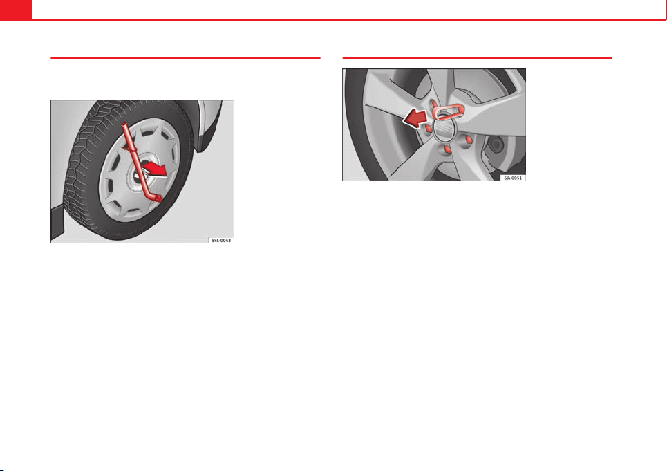
236 Emergencies
Wheel covers*
The wheel covers must be removed for access to the wheel
bolts
Fig. 119 Remove the
complete hub cap
Removing
– Remove the wheel cover using the wire hook ⇒ Fig. 119.
– Hook this into one of the cut-outs of the wheel cover.
Fitting
– Fit the wheel cover onto the wheel rim by pressing it firmly. Put
pressure initially on the point of the cut-out for the valve. Next
fit the rest of the hubcap
Removing the wheel bolt caps*
Fig. 120 Wheel: wheel
bolts with caps
Removal
– Fit the plastic clip (vehicle tools) over the cap until it clicks into
place ⇒ Fig. 120.
– Remove the cap with the plastic clip.
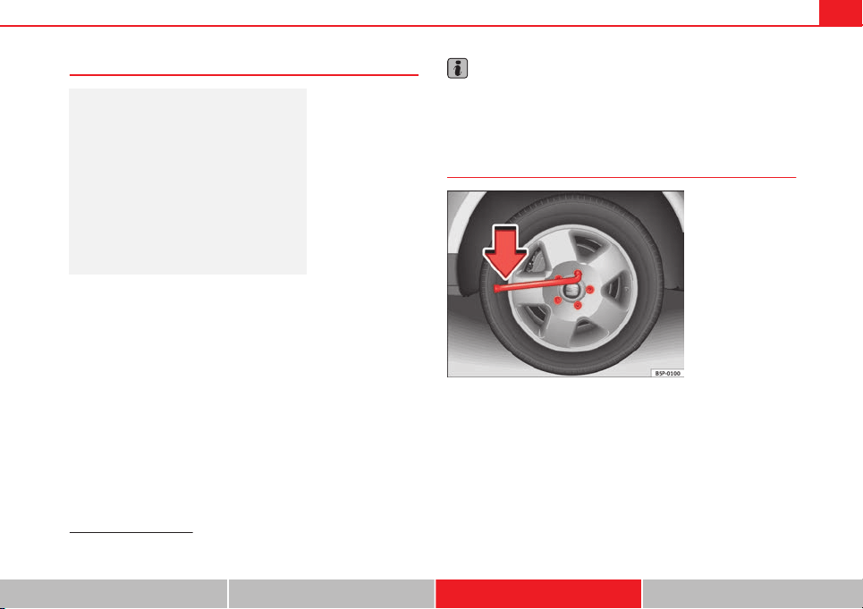
237Emergencies
Anti-theft wheel bolts
Fig. 121 Anti-theft
wheel bolt with cap and
adapter
A special adapter (vehicle tools) is required to remove the anti-
theft wheel bolts.
– Remove the wheel cover* or the cap*.
– Insert the adapter onto the anti-theft wheel bolt and push it on
as far as it will go.
– Insert the wheel brace (vehicle tools) onto the adapter as far as
it will go.
– Remove the wheel bolt ⇒ page 237.
Note
Make a note of the code number of the anti-theft wheel bolt and keep it in a
safe place, but not in your vehicle. If you need a new adapter, you can ob-
tain it from the SEAT Official Service, indicating the code number.
Loosening the wheel bolts
Fig. 122 Wheel: loosen
the wheel bolts
– Insert the wheel brace (vehicle tools) onto the wheel bolt as far
as it will go
1)
.
– Turn the wheel bolt approximately one turn to the left
⇒
Fig. 122
-arrow-. To apply the required torque, hold the wheel brace at
the end. If it is not possible to loosen a wheel bolt, carefully ap-
ply pressure with one foot on the end of the wheel brace. Hold
on to the car for support and take care not to slip.
1)
An adapter is required to unscrew or tighten the anti-theft wheel bolts ⇒ page 237.
Safety First Operating instructions Practical Tips Technical specifications
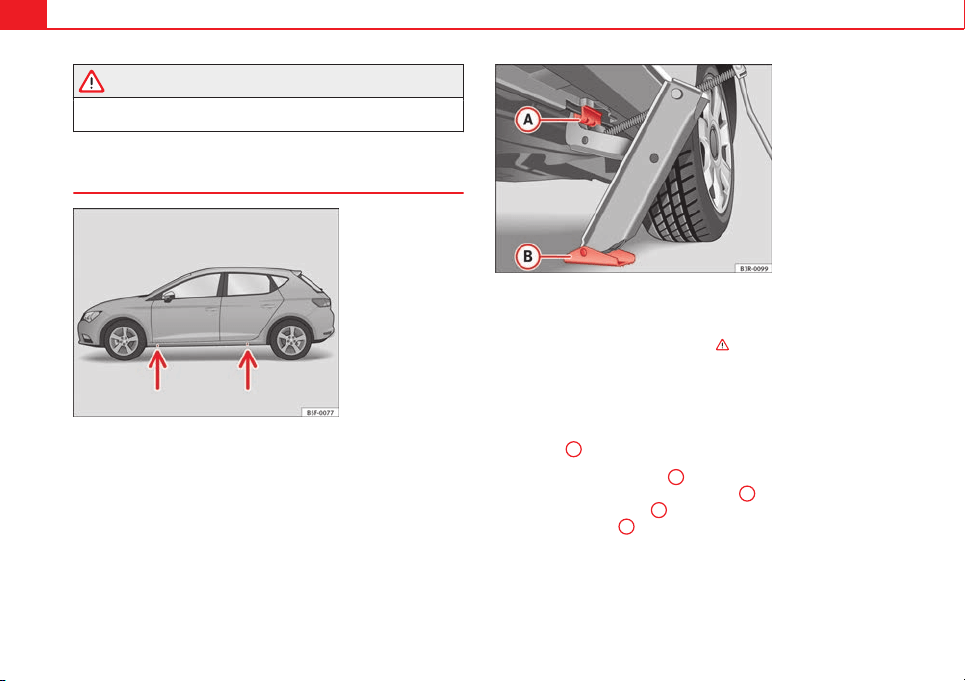
238 Emergencies
WARNING
Slightly loosen the wheel bolts (one turn) before raising the vehicle with
the jack*. If not, an accident may occur.
Raising the vehicle
Fig. 123 Crossbar:
makes
Fig. 124 Strut: mount-
ing the jack on the ve-
hicle
– Place the jack* (vehicle tools) on a firm surface. If necessary use
a large, strong board or similar support. If the surface is slip-
pery (for example, tiles), use a non-slip base underneath the
jack (for example, a rubber mat) ⇒
.
– Find the support point on the strut (sunken area) closest to the
wheel to be changed ⇒ Fig. 123. The jack* support point is be-
hind the mark on the strut.
– Turn the jack*, located below the strut support point, to raise it
until tab
A
⇒ Fig. 124 is below the plastic housing.
– Align the jack* so that tab
A
"grips" onto the plastic housing
on the strut and the mobile base plate
B
is resting on the
ground. The base plate
B
should fall vertically with respect to
the support point
A
.
– Continue turning the jack* until the wheel is slightly lifted off
the ground.

239Emergencies
WARNING
● Make sure that the jack* remains stable. If the surface is slippery or
soft, the jack* could slip or sink, respectively, with the resultant risk of
injury.
● Only raise the vehicle with the jack* supplied by the manufacturer.
Other vehicles could slip, with the consequent risk of injury.
● Only mount the jack* on the support points designed for this purpose
on the strut, and always align the jack correctly. If you do not, the jack*
could slip as it does not have an adequate grip on the vehicle: risk of in-
jury!
● The height of the parked vehicle can change as a result of variations
in temperature and loading.
CAUTION
The vehicle must not be raised on the crossbar. Only place the jack* on the
points designed for this purpose on the strut. Otherwise, the vehicle may be
damaged.
Removing and fitting a wheel
After loosening the wheel bolts and raising the vehicle with the
jack, change the wheel as described below:
Taking off the wheel
– Unscrew the wheel bolts using the box spanner and place them
on a clean surface.
– Take off the wheel
⇒
.
Putting on the spare wheel
When fitting tyres with a compulsory rotation direction, observe
the instructions in ⇒ page 239.
– Mount the wheel.
– Screw on the wheel bolts in position and tighten them loosely
with a box spanner.
– Carefully lower the vehicle using the jack*.
– Tighten the wheel bolts in diagonal pairs using the wheel
brace.
The wheel bolts should be clean and turn easily. Before fitting the spare
wheel, inspect the wheel condition and hub mounting surfaces. These sur-
faces must be clean before fitting the wheel.
CAUTION
When removing/fitting the wheel, the rim may hit and damage the brake
disc. For this reason, please take care and get a second person to assist
you.
Tyres with compulsory direction of rotation
A directional tread pattern can be identified by arrows on the sidewall that
point in the direction of rotation. Always observe the direction of rotation in-
dicated when mounting the wheel. This is important so that these tyres can
give maximum grip and avoid excessive noise, tread wear and aquaplaning.
If, exceptionally, it is necessary to mount the spare wheel* in the opposite
direction of rotation, please drive carefully, as in this case the tyre does not
have optimum conditions of use. This is particularly important when driving
on wet roads.
Safety First Operating instructions Practical Tips Technical specifications
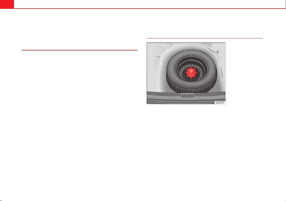
240 Emergencies
To benefit from the advantages of tyres with this type of tread pattern, the
defective tyre should be replaced as soon as possible so that all tyres again
rotate in the correct direction.
After changing a wheel
– On alloy wheels: replace the wheel bolt caps.
– On plate wheels: replace the wheel hubcap ⇒ page 236.
– Put the tools and jack back in the luggage compartment.
– If the replaced wheel does not fit in the spare wheel housing,
store it safely in the luggage compartment ⇒ page 17.
– Check the tyre pressure of the newly mounted tyre as soon as
possible.
– In vehicles fitted with a tyre pressure indicator, adjust the pres-
sure and store the reading in the radio/Easy Connect system*
⇒ page 175.
– The wheel bolts should be tightened to 120 Nm. Check the tor-
que as soon as possible with a torque wrench. Meanwhile, drive
carefully.
– Have the flat tyre replaced as quickly as possible.
Spare wheel
General information
Fig. 125 Compact tem-
porary spare wheel:
raised floor panel
The temporary spare wheel has been designed to be used for short
periods of time. Have the tyres checked, and if necessary, replaced
as soon as possible at a SEAT Official Service or at a specialised
workshop.
Please note the following restrictions when using the compact tem-
porary spare wheel. The compact temporary spare wheel is de-
signed specifically for this model. For this reason, do not use a
temporary spare wheel from a different type of vehicle.
Removing the temporary spare wheel
– Lift and hold up the floor panel to remove the temporary spare
wheel ⇒ Fig. 125.
– Turn the thumb wheel anti-clockwise.
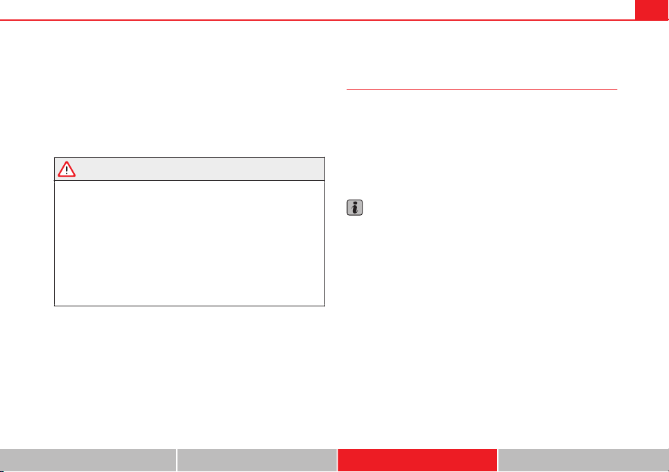
241Emergencies
– Take out the temporary spare wheel.
Chains
For technical reasons, snow chains must not be used on the temporary
spare wheel.
If you have a puncture on one of the front wheels when using snow chains,
fit the temporary spare wheel in place of one of the rear wheels. Fit the snow
chains on the rear wheel that you have removed and replace the punctured
front wheel with this wheel.
WARNING
● After fitting the temporary spare wheel, check the tyre pressures as
soon as possible. Failure to do so may cause an accident. The tyre pres-
sures are listed on the inside of the fuel tank flap.
● Do not drive at over 80 km/h (50 mph) when the temporary spare
wheel is fitted on the vehicle: risk of accident!
● Avoid heavy acceleration, hard braking and fast cornering: risk of ac-
cident!
● Never use more than one temporary spare wheel at the same time,
risk of accident.
● No other type of tyre (normal summer or winter tyre) may be fitted on
the compact temporary spare wheel rim.
Jump starting
Jump leads
The jump lead must have a sufficient wire cross section.
If the engine fails to start because of a discharged battery, the battery can
be connected to the battery of another vehicle to start the engine.
Jump leads
Jump leads must comply with standard DIN 72553 (see cable manufactur-
er's instructions). The wire cross section must be at least 25 mm
2
for petrol
engines and at least 35 mm
2
for diesel engines.
Note
● The vehicles must not touch each other, otherwise electricity could flow
as soon as the positive terminals are connected.
● The discharged battery must be properly connected to the on-board net-
work.
Safety First Operating instructions Practical Tips Technical specifications
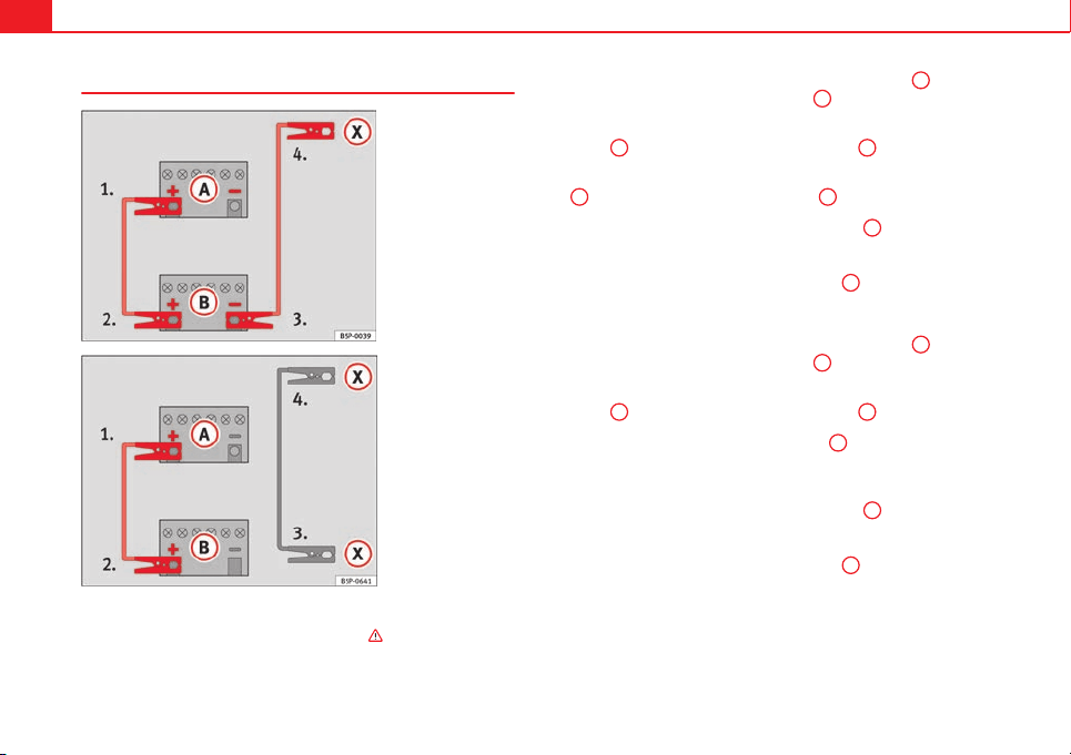
242 Emergencies
How to jump start: description
Fig. 126 Diagram of con-
nections for vehicles
without Start Stop sys-
tem
Fig. 127 Diagram of con-
nections for vehicles
with Start Stop system
Jump lead terminal connections
1. Switch off the ignition of both vehicles ⇒
.
2. For vehicles without Start-Stop system:
– Connect one end of the red jump lead to the positive
+
termi-
nal of the vehicle with the flat battery
A
⇒ Fig. 126.
– Connect the other end of the red jump lead to the positive ter-
minal
+
in the vehicle providing assistance
B
.
– Connect one end of the black jump lead to the negative terminal
–
of the vehicle providing assistance
B
⇒ Fig. 126.
– Connect the other end of the black jump lead
X
to a solid met-
al component bolted to the engine block or to the engine block
itself of the vehicle with the flat battery. However, connect it to
a point as far as possible from the battery
A
.
3. For vehicles with Start-Stop system:
– Connect one end of the red jump lead to the positive
+
termi-
nal of the vehicle with the flat battery
A
⇒ Fig. 127.
– Connect the other end of the red jump lead to the positive ter-
minal
+
in the vehicle providing assistance
B
.
– Connect one end of the black jump lead
X
to a suitable ground
terminal, a solid piece of metal in the engine block, or to the en-
gine block ⇒ Fig. 127.
– Connect the other end of the black jump lead
X
to a solid met-
al component bolted to the engine block or to the engine block
itself of the vehicle with the flat battery. However, connect it to
a point as far as possible from the battery
A
.
4. Position the leads in such a way that they cannot come into
contact with any moving parts in the engine compartment.
243Emergencies
Starting
5. Start the engine of the vehicle with the boosting battery and let
it run at idling speed.
6. Start the engine of the vehicle with the flat battery and wait two
or three minutes until the engine is “running”.
Removing the jump leads
7. Before you remove the jump leads, switch off the dipped beam
headlights (if they are switched on).
8. Turn on the heater blower and heated rear window in the vehi-
cle with the flat battery. This helps minimise voltage peaks
which are generated when the leads are disconnected.
9. When the engine is running, disconnect the leads in reverse or-
der to the details given above.
Connect the battery clamps so they have good metal-to-metal contact with
the battery terminals.
If the engine fails to start, switch off the starter after about 10 seconds and
try again after about half a minute.
WARNING
● Please note the safety warnings referring to working in the engine
compartment ⇒ page 209.
● The battery providing assistance must have the same voltage as the
flat battery (12V) and approximately the same capacity (see imprint on
battery). Failure to comply could result in an explosion.
WARNING (Continued)
● Never use jump leads when one of the batteries is frozen. Danger of
explosion! Even after the battery has thawed, battery acid could leak and
cause chemical burns. If a battery freezes, it should be replaced.
● Keep sparks, flames and lighted cigarettes away from batteries, dan-
ger of explosion. Failure to comply could result in an explosion.
● Observe the instructions provided by the manufacturer of the jump
leads.
● Do not connect the negative cable from the other vehicle directly to
the negative terminal of the flat battery. The gas emitted from the battery
could be ignited by sparks. Danger of explosion.
● Do not attach the negative cable from the other vehicle to parts of the
fuel system or to the brake line.
● The non-insulated parts of the battery clamps must not be allowed to
touch. The jump lead attached to the positive battery terminal must not
touch metal parts of the vehicle, this can cause a short circuit.
● Position the leads in such a way that they cannot come into contact
with any moving parts in the engine compartment.
● Do not lean on the batteries. This could result in chemical burns.
Note
The vehicles must not touch each other, otherwise electricity could flow as
soon as the positive terminals are connected.
Safety First Operating instructions Practical Tips Technical specifications
244 Emergencies
Towing and tow-starting the vehicle
General information
Points to observe when tow-starting or towing away
If you use a tow rope:
Notes for the driver of the towing vehicle
– The tow rope must be taut before you drive off.
– Release the clutch very carefully when starting the vehicle
(manual gearbox), or accelerate gently (automatic gearbox).
Notes for the driver of the towed vehicle
– The ignition should be switched on so that the turn signals,
horn, windscreen wipers and washers can be used. Please en-
sure that the steering wheel is unlocked when you switch on the
ignition, and that it moves freely.
– Put the gearbox lever in neutral (manual gearbox) or move the
selector lever to position N (automatic gearbox).
– The brake servo only works when the engine is running. Consid-
erably more effort is required on the brake pedal when the en-
gine is switched off.
– Remember that the brake servo only works when the ignition is
switched on and the vehicle is moving
1)
. Otherwise, considera-
bly more strength than usual will be required when steering.
– Ensure that the tow rope remains taut at all times.
Tow rope or tow bar
It is easier and safer to tow a vehicle with a tow bar. You should only use a
tow rope if you do not have a tow bar.
A tow rope should be slightly elastic to avoid damage to both vehicles. It is
advisable to use a tow rope made of synthetic fibre or similarly elastic mate-
rial.
Only attach the tow rope or the tow bar to the towing rings ⇒ page 245.
Driving style
Towing requires some experience, especially when using a tow rope. Both
drivers should be familiar with the technique required for towing. Inexper-
ienced drivers should not attempt to tow.
Do not pull too hard with the towing vehicle and take care to avoid jerking
the tow rope. When towing on an unpaved road, there is always a risk of
overloading and damaging the anchorage points.
WARNING
If the vehicle has no electrical power, the brake lights, turn signals and
all other lights will no longer function. Do not have the vehicle towed
away. Failure to do so could result in an accident.
CAUTION
If there is no oil in the gearbox or no lubricant in the automatic transmission
the car may only be towed with the driven wheels lifted clear of the road, or
transported on a special car transporter or trailer.
1)
Important: the battery must be correctly charged.
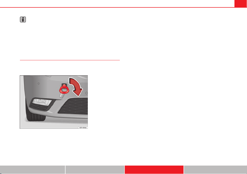
245Emergencies
Note
● Please observe legal requirements when doing so.
● Switch on the hazard warning lights of both vehicles. However, observe
any regulations to the contrary.
● The tow rope must not be twisted. Otherwise the front towline anchor-
age could be pulled off the vehicle.
Towline anchorage at the front of the vehicle
The front towline anchorage is only mounted if the vehicle
has to be towed.
Fig. 128 Right side of
the front bumper: towline
anchorage screwed in
There is a cover with an opening into which the towline anchorage
is screwed on the right part of the front bumper.
– To remove the bumper cover, just press the upper left side in-
wards.
– Take the towline anchorage out of the vehicle tool kit
⇒ page 232.
– Screw the towline anchorage into the screw connection as far as
it will go ⇒ Fig. 128 and tighten with the wheel brace.
After use, unscrew the towline anchorage and fit the cover back on the
bumper. Put the towline anchorage back in the vehicle tool kit. The towline
anchorage should always be kept in the vehicle.
Safety First Operating instructions Practical Tips Technical specifications
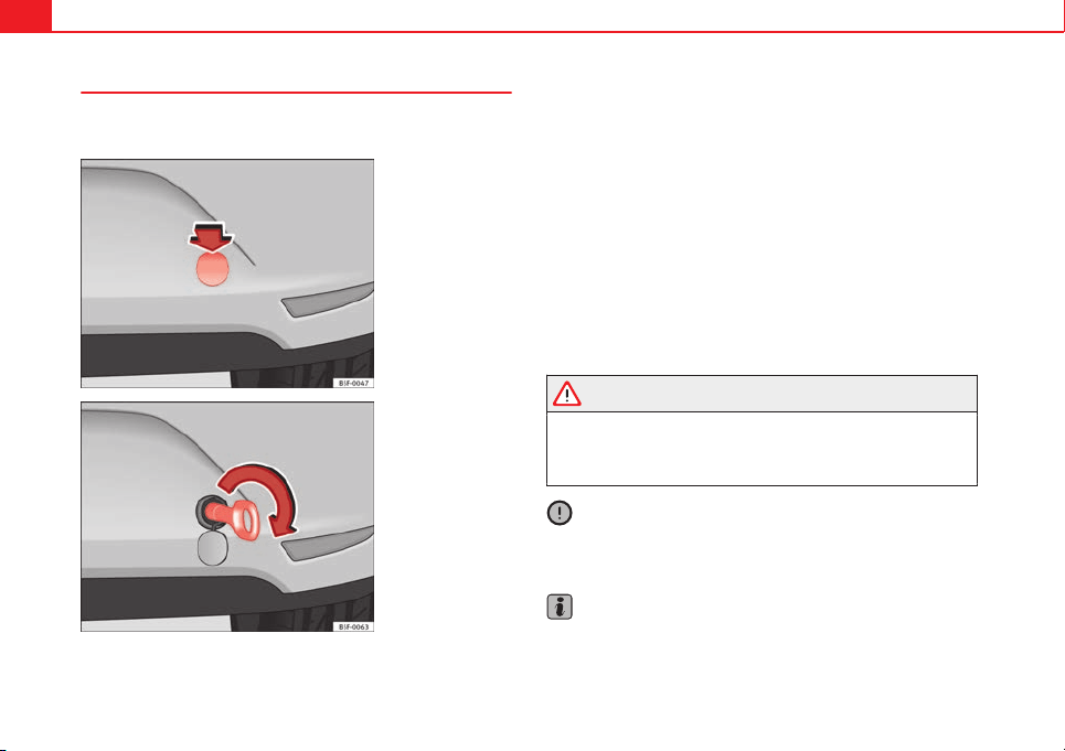
246 Emergencies
Rear towline anchorage
The rear towline anchorage should only be mounted if you
wish to tow another vehicle.
Fig. 129 Right side of
the rear bumper: cover
cap
Fig. 130 Right side of
the rear bumper: towline
anchorage screwed in
Vehicles with towline anchorage
On the right of the rear bumper there is a cover which covers a
threaded hole.
– Take the towline anchorage out of the vehicle tool set
⇒ page 232.
– To remove the bumper cover, press the upper side of the cover
inwards -arrow- and remove the cover by levering on the left
side ⇒ Fig. 129.
– Screw the towline anchorage into the screw connection as far as
it will go ⇒ Fig. 130 and tighten with the wheel brace.
After use, unscrew the towline anchorage and put it back in the vehicle tool
kit. Replace the cover on the bumper. The towline anchorage should always
be kept in the vehicle.
WARNING
● If the towline anchorage is not screwed in as far as the stop, there is a
risk of the screw connection shearing off during towing (accident risk).
● If your car has a towing bracket, only use special towing ropes. Risk
of accident!
CAUTION
In vehicles fitted with a towing bracket, only use special tow bars to prevent
damage to the ball joint. These tow bars have been specially approved for
use with towing brackets.
Note
If the vehicle is fitted with a towing hook, the ball must be fitted in it when
towing the vehicle.
247Emergencies
Tow-starting
As a general rule, tow-starting is not recommended.
– Engage 2nd or 3rd gear before moving off.
– Press the clutch and hold the pedal down.
– Switch the ignition on.
– Once both vehicles are moving, release the clutch.
– As soon as the engine starts: press the clutch and put the gear
lever in neutral.
If the engine will not start, it is best to try starting it using the battery of an-
other vehicle ⇒ page 241 before attempting to tow start. You should only try
to tow-start the engine if jump starting is not successful. Tow-starting is an
attempt to start the engine via the movement of the wheels.
When tow-starting a vehicle with a petrol engine, do not tow it more than a
short distance, otherwise sunburnt fuel can enter the catalytic converter and
cause damage.
WARNING
The risk of accidents is high when tow-starting, as the towed vehicle can
easily be driven into the towing vehicle.
CAUTION
Do not tow vehicles for more than 50 m. Risk of damage to the catalytic con-
verter.
Towing vehicles with a manual gearbox
Towing is relatively straightforward.
Please observe the relevant instructions ⇒ page 244.
The vehicle can be towed using a tow bar or tow rope in the normal way,
with all four wheels on the road; it can also be towed with either the front or
rear wheels lifted off the road. The maximum towing speed is 50 km/h (30
mph).
Towing a vehicle equipped with automatic gearbox
Certain restrictions must be observed when towing your ve-
hicle.
Please observe the relevant instructions ⇒ page 244.
The vehicle can be towed with a tow bar or tow rope in the normal way, with
all four wheels on the ground. When doing so, please note the following
points:
● Make sure the selector lever is in the N position.
● The vehicle must not be towed faster than 50 km/h (30 mph).
● The vehicle must not be towed further than 50 km (30 miles). Reason:
when the engine is not running, the gearbox oil pump does not work and
the gearbox is not adequately lubricated for higher speeds or longer distan-
ces.
If the vehicle has to be towed with a breakdown truck, it must only be sus-
pended at the front wheels. Reason: the drive shafts are located on the front
wheels. If the car is towed with the rear wheels lifted off the road (I.e. travel-
ling backwards), the drive shafts also turn backwards. The planetary gears
in the automatic gearbox then turn at such high speeds that the gearbox
will be severely damaged in a short time.
Safety First Operating instructions Practical Tips Technical specifications

248 Emergencies
Note
● If it is not possible to tow the vehicle in the normal way, or if it has to be
towed further than 50 km (30 miles), it must be transported on a special car
transporter or trailer.
● Should the power supply to the selector lever be interrupted in posi-
tion P, the selector lever will be locked. Before the vehicle can be recovered/
manoeuvred you must manually release the selector lever ⇒ page 163.
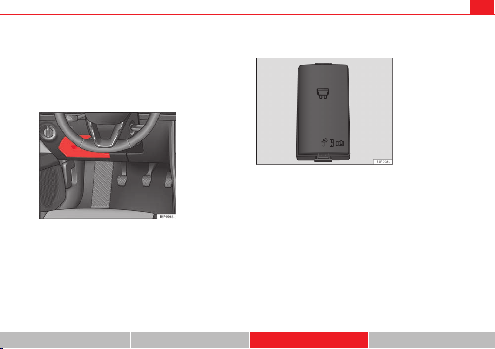
249Fuses and bulbs
Fuses and bulbs
Electrical fuses
Changing fuses
A blown fuse can be identified by the blown metal strip.
Fig. 131 Steering col-
umn area: cover
Fig. 132 Engine com-
partment, left-hand side:
fuse cover
Fuses in the steering column area
– Switch off the ignition and component concerned.
– Look in the tables below for the right fuse for the component
⇒ page 250.
– Remove the cover ⇒ Fig. 131.
– Remove the plastic clips from the fuse cover.
– Use the plastic clip to pull out the fuse and replace the blown
fuse with a fuse of the same rating.
Fuses in engine compartment
– Switch off the ignition and component concerned.
– Look in the tables below for the right fuse for the component
⇒ page 251.
Safety First Operating instructions Practical Tips Technical specifications
250 Fuses and bulbs
– Unlock the fuse cover ⇒ Fig. 132.
– Remove the clips from the fuse cover.
– Use the plastic clip to pull out the fuse and replace the blown
fuse with a fuse of the same rating.
The individual electrical circuits are protected by fuses. Fuses are located
under a cover below the steering wheel on the left side of the engine com-
partment.
WARNING
Do not repair fuses, and never replace a blown fuse with a higher amper-
age fuse. The electrical system could be damaged, with risk of fire.
CAUTION
● Multiple fuse values on the same line (for example, 5/10/20) in the fol-
lowing tables indicate equipment-related differences. Replace the blown
fuse with a fuse of the same amperage.
● If a newly replaced fuse blows again after a short time, the electrical sys-
tem must be checked by a specialised workshop as soon as possible.
Note
● Positions are not occupied by a fuse do not appear in the following ta-
bles.
● Some of the equipment listed in the tables below pertain only to certain
versions of the model or are an optional extra.
Fuses in the vehicle interior
No. Electrical consumer Amps
F2 Vacant -
F4 Alarm 10
F5 Gateway 5
F6 Anti-theft alarm system 5
F7
Air conditioner/heating control panel, selector
lever (automatic gearbox), relay coil, rear win-
dow heating, additional heating
10
F8
Diagnosis, handbrake switch, light switch, re-
verse light, interior lighting
10
F9 Vacant -
F10 Radio display 10
F11 Vacant -
F12 Radio 20
F13 Vacant -
F14 Air conditioner fan 40
F15 Vacant -
F16 Vacant -
F17 Instrument panel 5
F18 Vacant -
F19 Vacant -
F20 Vacant -
F23 Right lights 40
F24 Sunroof 30
F25 Left door 30
F26 Heated seats 30
F27 Vacant -
F28 Vacant -
251Fuses and bulbs
No. Electrical consumer Amps
F29 Vacant -
F30
Vacant -
F31 Left lights 40
F32 Parking aid control unit 7,5
F33 Airbag 5
F34
Reverse switch, clima sensor, electrochromic
mirror
7,5
F35
Diagnosis, headlight control unit, headlight ad-
juster
10
F36 Front camera 10
F37 Vacant -
F38 Vacant -
F39 Right door 30
F40 12V socket 20
F41 Steering column 20
F42 Central locking 40
F43 Interior light 30
F44 Vacant -
F45 Vacant -
F47 Rear window wiper 15
F49 Starter motor; clutch sensor 5
F51 Vacant -
F53 Heated rear window 30
The electric windows and electric seats* are protected by circuit breakers.
These switch on again automatically after a few seconds when the overload
(caused for example by frozen windows) has been corrected.
Note
Please note that the above list, while correct at the time of printing, is sub-
ject to alterations.
Fuses on left side of engine compartment
No. Electrical consumer Amps
F1 Vacant -
F2 ESC control unit 40
F3 Engine control unit (diesel/petrol) 15/30
F4 Engine sensors 5/10
F5 Engine sensors 7,5/10
F6 Brake light sensor 5
F7 Engine power supply 5/10
F8 Lambda probe 10
F9 Engine 5/10/20
F10 Fuel pump control unit 15/20
F11 PTC 40
F12 PTC 40
F13 Automatic gearbox control unit 15/30
F15 Horn 15
F16 Fuel pump control unit 20
F17 Engine control unit 7,5
F18 Terminal 30 (positive reference) 5
F19 Front windscreen washer 30
F20 Alarm horn 10
F22 Engine control unit 5
F23 Starter motor 30
Safety First Operating instructions Practical Tips Technical specifications
252 Fuses and bulbs
No. Electrical consumer Amps
F24 PTC 40
F31
Vacant -
F32 Vacant -
F37 Vacant -
Note
Please note that the above list, while correct at the time of printing, is sub-
ject to alterations.
Bulbs
Changing a bulb
Changing bulbs requires a certain degree of practical skill.
If you choose to change engine compartment lamps yourself, remember
that it is a dangerous area ⇒
in Working on components in the engine
compartment on page 209.
Always use identical bulbs with the same designation. The name can be
found on the base of the bulb holder.
Depending on how equipped the vehicle is, there are different sets of head-
lights and tail lights:
● Halogen headlights
● Full-LED main headlights*
● Rear bulb light
● LED rear light*
Full-LED headlight system*
Full-LED headlights handle all light functions (daylight, side light, turn sig-
nal, dipped beam and route light) with light emitting diodes (LEDs) as a
light source.
Full-LED headlights are designed to last the lifetime of the car and light
bulbs cannot be replaced. In case of headlight failure, go to an authorised
workshop to have it replaced.
Bulbs (12 V)
Halogen headlights Type
Daytime driving light/side light P21W SLL
Dipped beam headlights H7 LL
Main beam headlights H7 LL
Turn signal PY21W LL
Full-LED main headlights Type
No bulbs may be replaced. All functions are
with LEDs
Front fog light Type
Fog light/cornering* H8
Rear bulb light Type
Brake lights/tail lights P21W LL
Side lights 2x W5W LL
Turn signal PY21W LL
Rear fog light H21W
Reverse lights P21W LL
LED rear light Type
Turn signal PY21W LL
Rear fog light H21W
253Fuses and bulbs
LED rear light Type
Reverse lights P21W LL
The remaining functions work with LEDs
WARNING
● Take particular care when working on components in the engine com-
partment if the engine is warm. Risk of burns.
● Bulbs are highly sensitive to pressure. The glass can break when you
touch the bulb, causing injury.
● When changing bulbs, please take care not to injure yourself on sharp
edges, in particular on the headlight housing.
CAUTION
● Remove the ignition key before working on the electric system. Other-
wise, a short circuit could occur.
● Switch off the lights or parking lights before you change a bulb.
● Take good care to avoid damaging any components.
For the sake of the environment
Please ask your specialist retailer how to dispose of used bulbs in the prop-
er manner.
Note
● Please check at regular intervals that all lighting (especially the exterior
lighting) on your vehicle is functioning properly. This is not only in the inter-
est of your own safety, but also that of all other road users.
● Before changing a bulb, make sure you have the correct new bulb.
● Do not touch the glass part of the bulb with your bare hands, use a cloth
or paper towel instead. Otherwise, the fingerprints left on the glass will va-
porise as a result of the heat generated by the bulb, they will be deposited
on the reflector and will impair its surface.
Safety First Operating instructions Practical Tips Technical specifications
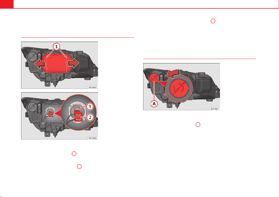
254 Fuses and bulbs
Changing bulbs in headlight unit
Dipped beam bulb
Fig. 133 Dipped beam
headlights
Fig. 134 Dipped beam
headlights
– Raise the bonnet
– Move the loops ⇒ Fig. 133
1
in the direction of the arrow and
remove the cover.
– Remove connector ⇒ Fig. 134
2
from the bulb.
– Unclip the retainer spring ⇒ Fig. 134
3
pressing inwards to the
right.
– Extract the bulb and fit the replacement so that the rim of the
attachment plate is on the reflector cut-out.
Daylight bulb
Fig. 135 Daylight bulb
– Raise the bonnet.
– Turn bulb holder ⇒ Fig. 135
A
to the left and pull.
– Remove the bulb by pressing on the bulb holder and turning it
anti-clockwise at the same time.
– Installation involves all of the above steps in reverse sequence.
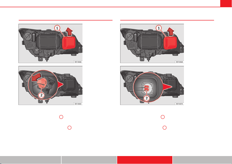
255Fuses and bulbs
Turn signal bulb
Fig. 136 Turn signal bulb
Fig. 137 Turn signal bulb
– Raise the bonnet
– Move the loop ⇒ Fig. 136
1
in the direction of the arrow and
remove the cover.
– Turn the bulb holder ⇒ Fig. 137
2
to the left and pull.
–
Remove the bulb by pressing on the bulb holder and turning it
anti-clockwise at the same time.
– Installation involves all of the above steps in reverse sequence.
Main beam bulb
Fig. 138 Main beam
bulb
Fig. 139 Main beam
bulb
– Raise the bonnet
– Move the loop ⇒ Fig. 138
1
in the direction of the arrow and
remove the cover.
– Slide connector ⇒ Fig. 139
2
to the left or right and pull.
–
Remove the bulb by disconnecting the connector.
– Installation involves all of the above steps in reverse sequence.
Safety First Operating instructions Practical Tips Technical specifications
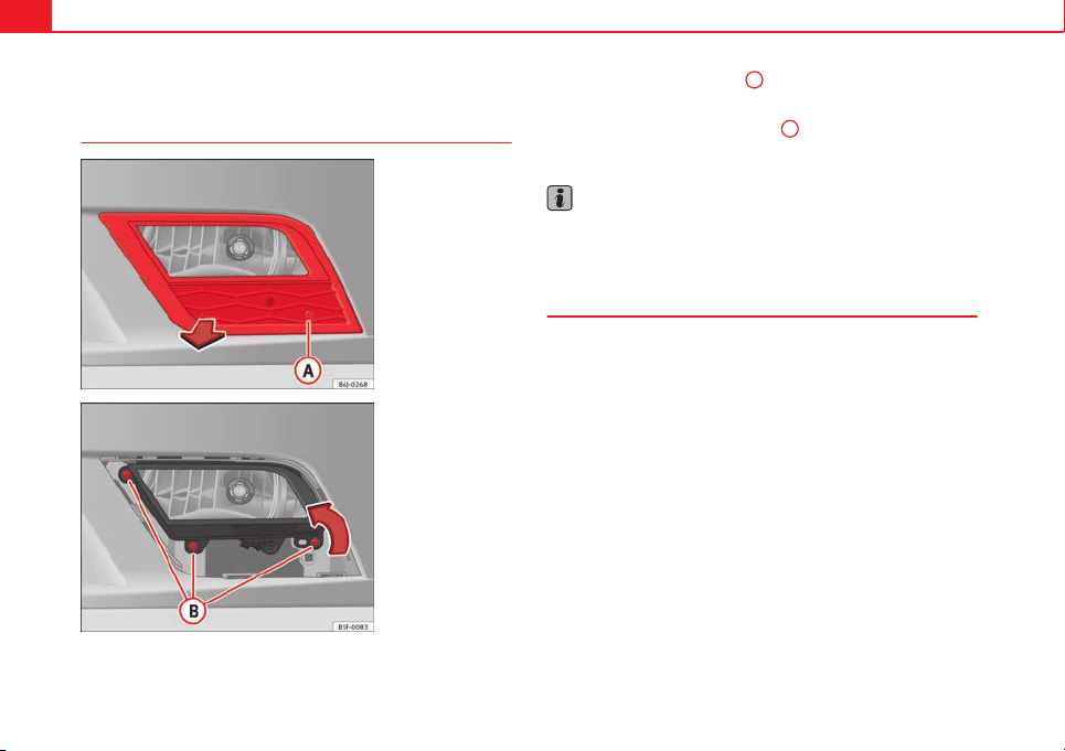
256 Fuses and bulbs
Changing bulb for front fog light
Front fog light bulb
Fig. 140 Front fog light
Fig. 141 Front fog light
– Remove the bolt ⇒ Fig. 140
A
from the fog light grille with a
screwdriver.
– Remove the bolts (3x) ⇒ Fig. 141
B
to remove the fog light.
– Remove the fog light.
Note
Due to the difficulty of accessing fog light bulbs, have them replaced at a
Technical Service or specialised workshop.
Fog light, FR version
Due to the difficulty of accessing fog light bulbs, have them replaced at a
Technical Service or specialised workshop.
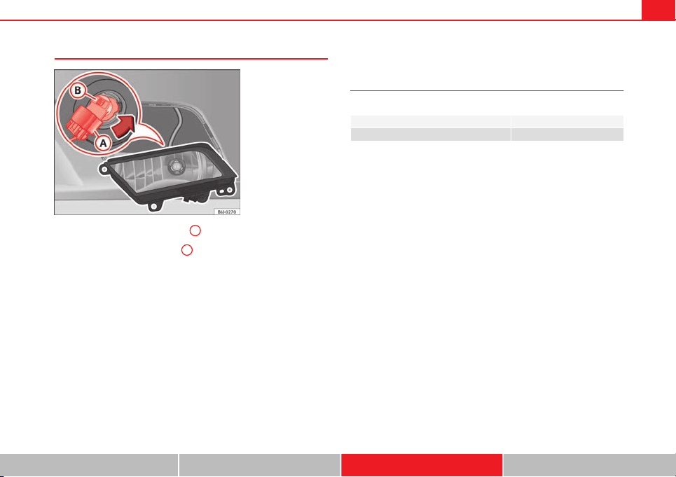
257Fuses and bulbs
Remove the bulb holder
Fig. 142 Front fog light
– Remove connector ⇒ Fig. 142
A
from the bulb.
– Turn bulb holder ⇒ Fig. 142
B
to the left and pull.
– Remove the bulb by pressing on the bulb holder and turning it
anti-clockwise at the same time.
– Installation involves all of the above steps in reverse sequence.
– Check that the bulb works properly.
Changing tail light bulbs (on side panel)
Overview of tail lights
Rear lights on the side panel
Turn signal PY21W NA LL
Side light and brake light P21W LL
Safety First Operating instructions Practical Tips Technical specifications
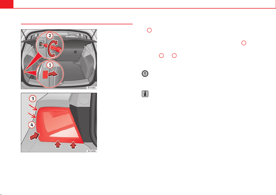
258 Fuses and bulbs
Removing tail light
Fig. 143 Luggage com-
partment: Location of the
bolt securing the tail
light unit
Fig. 144 Remove rear
light unit from side panel
– Check which of the bulbs is defective.
– Open the rear lid.
– Remove the cover by prying the flat side of a screwdriver into
the recess and remove the cover from the opening ⇒ Fig. 143
1
.
– Carefully loosen the screw located behind the cover with a
screwdriver, turning it anti-clockwise (arrows) ⇒ Fig. 143
2
.
– Tilt the light in the direction of the arrows until it comes out (po-
sitions
3
and
4
⇒ Fig. 144).
– Remove the bulb holder ⇒ page 259.
CAUTION
Take care when removing the rear light unit to make sure there is no dam-
age to the paintwork or any of its components.
Note
Make sure you have a soft cloth ready to place under the glass on the rear
light unit, to avoid any scratches.
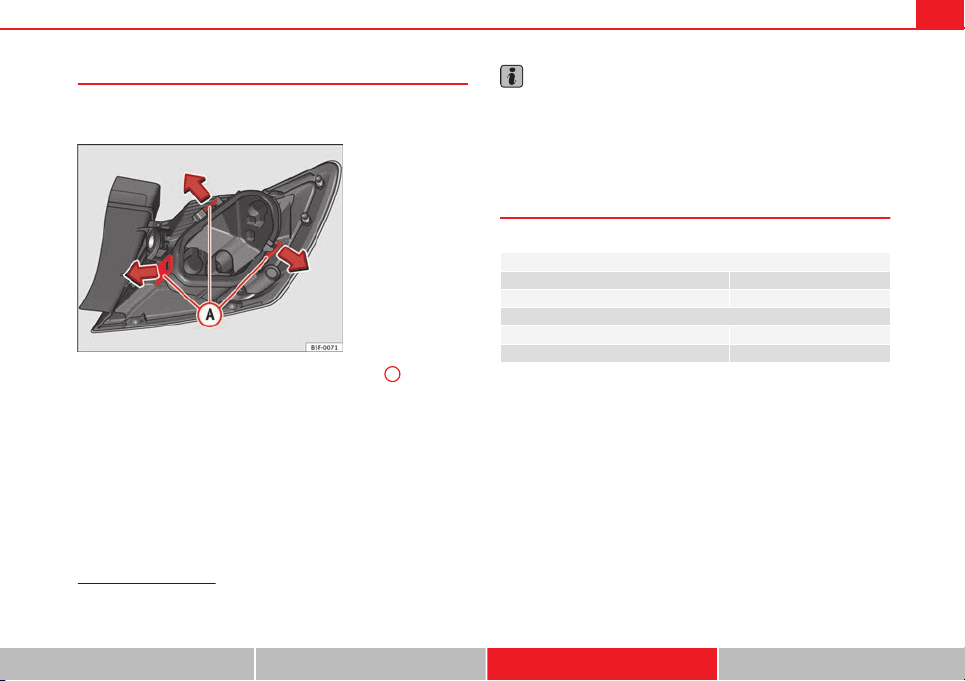
259Fuses and bulbs
Remove the bulb holder
When changing a bulb, you must first remove the bulb hold-
er.
Fig. 145 Retaining tabs
on reverse side of tail
light
– Remove the bulb holder ⇒ Fig. 145 unlocking the
A
retaining
tabs.
– Raise the bulb holder.
– Change the defective bulb.
– To refit follow the steps in reverse order, taking special care
when fitting the bulb holder. And especially that all retaining
tabs are properly in place.
– Place the light back into place and tighten with a screwdriver.
Note
In the case of LED lights, change only the turn signal bulb.
Changing tail light bulbs (on rear lid)
Overview of tail lights
Rear lid lights
1)
Left side
Side lights 2x W5W LL
Fog lights H21 W
Right side
Side lights 2x W5W LL
Reverse light P21W LL
1)
The above table corresponds to a right-hand traffic vehicle. The position of lights may vary
according to the country.
Safety First Operating instructions Practical Tips Technical specifications
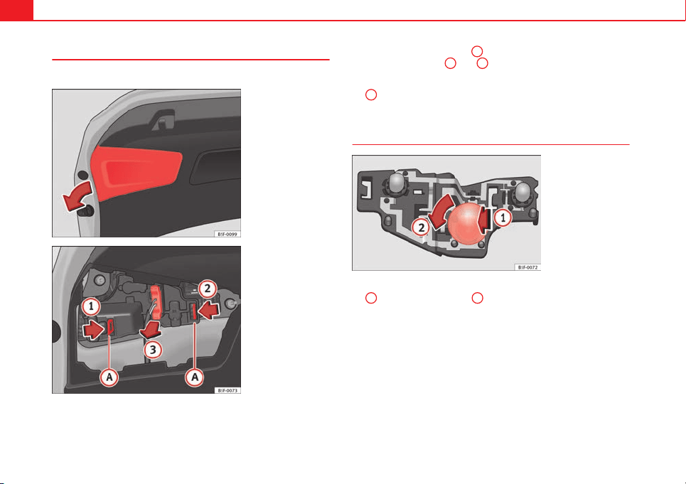
260 Fuses and bulbs
Remove the bulb holder
The rear lid must be open to change the bulbs.
Fig. 146 Remove the
cover from the rear lid
Fig. 147 Remove the
bulb holder
– Remove the rear lid cover in the direction indicated ⇒ Fig. 146.
– Unlock the retaining tabs
A
of the bulb holder, following the
direction of arrows
1
and
2
⇒ Fig. 147.
– Remove the bulb holder by turning it in the direction of arrow
3
⇒ Fig. 147.
Changing bulbs
Fig. 148 Position of the
bulbs in the bulb holder
– Lightly press the defective bulb into the bulb holder ⇒ Fig. 148
1
, then turn it to the left
2
and remove it.
– Fit the new bulb, pressing it into the bulb holder and turn it to
the right as far as it will go.
– Use a cloth to remove any fingerprints from the glass part of the
bulb.
– Check that the new bulb works properly.
– Replace the bulb holder.
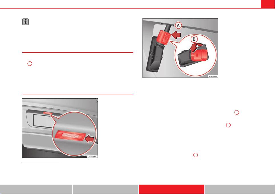
261Fuses and bulbs
Note
For LED pilots, you can only change the fog or reverse bulb, on the left or
right guide.
Fitting the bulb holder
– Install the bulb holder making sure that locking clips ⇒ Fig. 147
A
are properly clipped on.
– Replace the cover of the rear lid lining ⇒ Fig. 146.
Changing number plate light bulbs
1)
Fig. 149 In the rear
bumper: number plate
light
Fig. 150 Number plate
light: remove the bulb
holder
Follow the steps indicated:
1. Press the number plate light in the direction of the arrow
⇒ Fig. 149.
2. Remove the number plate bulb slightly.
3. In the connector lock, turn ⇒ Fig. 150 towards arrow
A
and pull
the connector.
4. Rotate the bulb holder in the direction of arrow
B
and extract it
with the bulb.
5. Replace the defective bulb with a new bulb with the same fea-
tures.
6. Insert the bulb holder in the number plate light and turn in the
opposite direction of arrow
B
until it stops.
1)
Depending on how equipped the vehicle is, the number plate lights may be LEDs. LEDs
have an estimated life that exceeds than that of the car. If a light with LEDs fails, go to an
authorised workshop for replacement.
Safety First Operating instructions Practical Tips Technical specifications

262 Fuses and bulbs
7. Plug the connector into the bulb holder.

263Technical specifications
Technical specifications
Technical specifications
Important
The information in your vehicle's official documents always
take precedence over the information in the current instruc-
tion manual.
All technical specifications provided in this documentation are valid for the
standard model in Spain. The vehicle data card included in the Mainte-
nance Programme or the vehicle registration documentation shows which
engine is installed in the vehicle.
The figures may be different depending whether additional equipment is fit-
ted, for different models, for special vehicles and for other countries.
Abbreviations used in the Technical Specifications section
Abbrevia-
tion
Meaning
kW Kilowatt, engine power measurement.
PS
Pferdestärke (horsepower), formerly used to denote engine
power.
rpm Revolutions per minute - engine speed.
Nm Newton metres, unit of engine torque.
litres per
100 km
Fuel consumption in litres per 100 km (70 miles).
g/km Carbon dioxide emissions in grams per km (mile) travelled.
CO
2
Carbon dioxide
CN Cetane number, indication of the diesel combustion power.
RON
Research octane number, indication of the knock resistance
of petrol.
Safety First Operating instructions Practical Tips Technical specifications
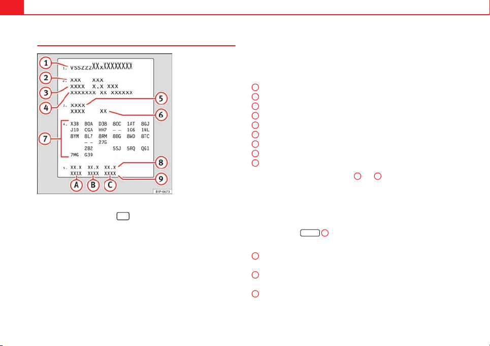
264 Technical specifications
Vehicle identification data
Fig. 151 Vehicle data
sticker (luggage compart-
ment)
Chassis number in the Easy Connect
– Select: Function button
CAR
> control button (Car)* Systems >
Service & Control > Chassis number.
Chassis number
The chassis number is located in the Easy Connect, on the vehicle data
sticker and under the windscreen, on the driver side. Additionally, the chas-
sis number is located in the engine compartment, on the right-hand side.
The number is engraved on the top side rail, and is partially covered.
Type plate
The type plate is located on the right side door pillar. Vehicles for certain
export countries do not have a type plate.
Vehicle data sticker
The vehicle data sticker is under the carpet trim in the luggage compart-
ment, in the spare wheel well. A sticker with the vehicle data is attached to
the inside cover of the Maintenance Programme.
The following information is provided on the vehicle data sticker: ⇒ Fig. 151
Production control number
Vehicle identification number (chassis number)
Model code number
Model designation/engine power output
Engine and gearbox code letters
Paintwork number/interior trim code
Optional equipment codes
Consumption values
CO
2
emissions values
At the end of the data sticker, in points
8
and
9
, you can see the con-
sumption and emission information.
Identifying letters
The identifying letters of the engine can be viewed on the instrument panel.
Important: The engine must be off and the ignition on.
● Hold down the
0.0/SET
4
⇒ Fig. 36 button for more than 15 seconds.
Information on consumption and emissions
Urban consumption (l/100 km)
Urban CO
2
emissions (g/km)
Extra-urban consumption (l/100 km)
Extra-urban CO
2
emissions (g/km)
Combined consumption (l/100 km)
Combined CO
2
emissions (g/km)
1
2
3
4
5
6
7
8
9
A
B
C
265Technical specifications
Information on fuel consumption
Fuel consumption
The consumption and emission details shown on the vehicle
data sticker differ from one vehicle to another.
The vehicle fuel consumption and CO
2
emissions can be consulted on the
vehicle data sticker in the spare wheel well, inside the luggage compart-
ment and on the rear cover of the Maintenance Programme.
The fuel consumption and CO
2
emission values refer to the weight category
assigned to your vehicle according to the engine and gearbox combination,
as well as the specific equipment fitted, and is only used to compare be-
tween the different models.
The fuel consumption and CO
2
emissions do not depend only on the per-
formance of the vehicle, they can also differ from the established values de-
pending on other factors such as driving style, road conditions, traffic con-
ditions, environmental conditions, load and number of passengers.
Calculation of fuel consumption
The consumption values have been calculated based on measurements per-
formed or supervised by certified CE laboratories according to the latest ver-
sion of directives 715/2007/EC and 80/1268/CEE (for more information
consult the European Union Publications Office at EUR-Lex: © European Un-
ion, http://eur-lex.europa.eu/en/index.htm) and are valid for the kerb
weight indicated for the vehicle.
Note
In practice, and considering all the factors mentioned here, consumption
values can differ from those calculated in the current European regulations.
Weights
Kerb weight refers to the basic model with a fuel tank filled to 90% capacity
and without optional extras. The figure quoted includes 75 kg to allow for
the weight of the driver.
For special versions and optional equipment fittings or for the addition of
accessories, the weight of the vehicle will increase ⇒
.
WARNING
● Please note that the centre of gravity may shift when transporting
heavy objects; this may affect vehicle handling and lead to an accident.
Always adjust your speed and driving style to suit road conditions and re-
quirements.
● Never exceed the gross axle weight rating or the gross vehicle weight
rating. If the allowed axle load or the allowed total weight is exceeded,
the driving characteristics of the vehicle may change, leading to acci-
dents, injuries and damage to the vehicle.
Towing a trailer
Trailer weights
Trailer weight
The trailer weights and drawbar loads approved are selected in intensive tri-
als according to precisely defined criteria. The approved trailer weights are
valid for vehicles in the EU for maximum speeds of 80 km/h (50 mph) (in
certain circumstances up to 100 km/h, 60 mph). The figures may be differ-
ent in other countries. All data in the official vehicle documentation takes
precedence over these data at all times ⇒
.
Safety First Operating instructions Practical Tips Technical specifications
266 Technical specifications
Drawbar loads
The maximum permitted drawbar load on the ball joint of the towing bracket
must not exceed 80 kg.
In the interest of road safety, we recommend that you always tow approach-
ing the maximum drawbar load. The response of the trailer on the road will
be poor if the drawbar load is too small.
If the maximum permissible drawbar load cannot be met (e.g. with small,
empty and light-weight single axle trailers or tandem axle trailers with a
wheelbase of less than 1 metre), a minimum of 4% of the actual trailer
weight is legally required for the drawbar load.
WARNING
● For safety reasons, do not exceed the 80 km/h (50 mph) limit. This is
also valid in countries where higher speeds are permitted.
● Never exceed the maximum trailer weights or the drawbar load. If the
permissible axle load or the permissible total weight is exceeded, the
driving characteristics of the vehicle may change, leading to accidents,
injuries and damage to the vehicle.
Wheels
Tyre pressure, snow chains, wheel bolts
Tyre pressures
The sticker with the tyre pressure values can be found on the inside of the
fuel tank flap. The tyre pressure values given there are for cold tyres. The
slightly raised pressures of warm tyres must not be reduced. ⇒
Snow chains
Snow chains may be fitted only to the front wheels, and only for the follow-
ing tyres:
175/70R14
185/60R15
Chains with links not exceeding 15 mm (including the chain
closure)
215/45R16 Chains with links not exceeding 9 mm (including the chain
closure)
215/40R17 Chains with links not exceeding 7 mm (including the chain
closure)
Wheel bolts
After the wheels have been changed, the tightening torque of the wheel
bolts should be checked as soon as possible with a torque wrench ⇒
.
The tightening torque for steel and alloy wheels is 120 Nm.
WARNING
● Check the tyre pressure at least once per month. Checking the tyre
pressure is very important. If the tyre pressure is too high or too low,
there is an increased danger of accidents, particularly at high speeds.
● If the tightening torque of the wheel bolts is too low, they could loos-
en while the vehicle is in motion. Risk of accident! If the tightening tor-
que is too high, the wheel bolts and threads can be damaged.
Note
We recommend that you ask your Technical Service for information about
appropriate wheel, tyre and snow chain size.
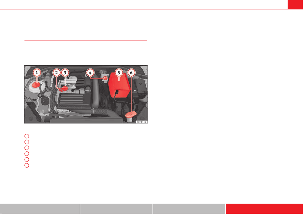
267Technical specifications
Engine specifications
Checking fluid levels
From time to time, the levels of the different fluids in the ve-
hicle must be checked. Never fill with incorrect fluids, other-
wise serious damage to the engine may be caused.
Fig. 152 Diagram for the location of the various elements
Coolant expansion tank
Engine oil dipstick
Engine oil filler cap
Brake fluid reservoir
Vehicle battery (underneath the cover)
Windscreen washer reservoir
The checking and refilling of service fluids are carried out on the compo-
nents mentioned above. These operations are described in ⇒ page 209.
1
2
3
4
5
6
Overview
You will find further explanations, instructions and restrictions on the tech-
nical specifications as of ⇒ page 263.
Safety First Operating instructions Practical Tips Technical specifications
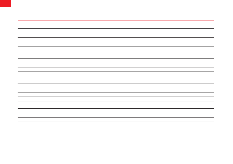
268 Technical specifications
Petrol engine 1.2 63 kW (85 PS)
Engine specifications
Power output in kW (PS) rpm 63 (85)/ 4300-5300
Maximum torque in Nm at rpm 160/ 1400-3500
No. of cylinders/capacity in cm
3
4/ 1197
Fuel Super 95 RON
a)
a)
Research Octane Number = Anti-detonation rating of the petrol.
Performance
Maximum speed in km/h (mph) 179 (V)
Acceleration from 0-80 km/h (0-60 mph) in sec. 7,7
Acceleration from 0-100 km/h (0-60 mph) in sec. 11,7
Weights
Gross vehicle weight in kg 1720
Weight in running order (with driver) in kg 1192
Gross front axle weight in kg 910
Gross rear axle weight in kg 860
Permitted roof load in kg 75
Trailer weight
Trailer without brakes in kg 590
Trailer with brakes, gradients up to 8% in kg 1300
Trailer with brakes, gradients up to 12% in kg 1100

269Technical specifications
Petrol engine 1.2 77 kW (105 PS)
Engine specifications
Power output in kW (PS) rpm 77 (105)/ 4500-5500
Maximum torque in Nm at rpm 175/ 1400-4000
No. of cylinders/capacity in cm
3
4/ 1197
Fuel Super 95 RON
a)
a)
Research Octane Number = Anti-detonation rating of the petrol.
Performance
Manual Start-Stop Automatic
Maximum speed in km/h (mph) 192 (V) 193 (V) 191 (VI)
Acceleration from 0-80 km/h (0-60
mph)
in sec. 6,7 6,6 6,8
Acceleration from 0-100 km/h (0-60
mph)
in sec. 10,1 10 10
Weights
Manual Start-Stop Automatic
Gross vehicle weight in kg 1720 1740 1760
Weight in running order (with driver) in kg 1194 1205 1229
Gross front axle weight in kg 910 920 950
Gross rear axle weight in kg 860 870 860
Permitted roof load in kg 75 75 75
Trailer weight
Manual Start-Stop Automatic
Trailer without brakes in kg 590 600 610
Trailer with brakes, gradients up to 8% in kg 1500 1500 1500
Trailer with brakes, gradients up to 12% in kg 1300 1300 1300
Safety First Operating instructions Practical Tips Technical specifications

270 Technical specifications
Petrol engine 1.4 90 kW (122 PS) Start-Stop
Engine specifications
Power output in kW (PS) rpm 90 (122)/ 5000-6000
Maximum torque in Nm at rpm 200/ 1400-4000
No. of cylinders/capacity in cm
3
4/ 1395
Fuel Super 95 RON
a)
a)
Research Octane Number = Anti-detonation rating of the petrol.
Performance
Maximum speed in km/h (mph) 202 (V)
Acceleration from 0-80 km/h (0-60 mph) in sec. 6,2
Acceleration from 0-100 km/h (0-60 mph) in sec. 9,3
Weights
Gross vehicle weight in kg 1760
Weight in running order (with driver) in kg 1224
Gross front axle weight in kg 930
Gross rear axle weight in kg 880
Permitted roof load in kg 75
Trailer weight
Trailer without brakes in kg 610
Trailer with brakes, gradients up to 8% in kg 1700
Trailer with brakes, gradients up to 12% in kg 1400
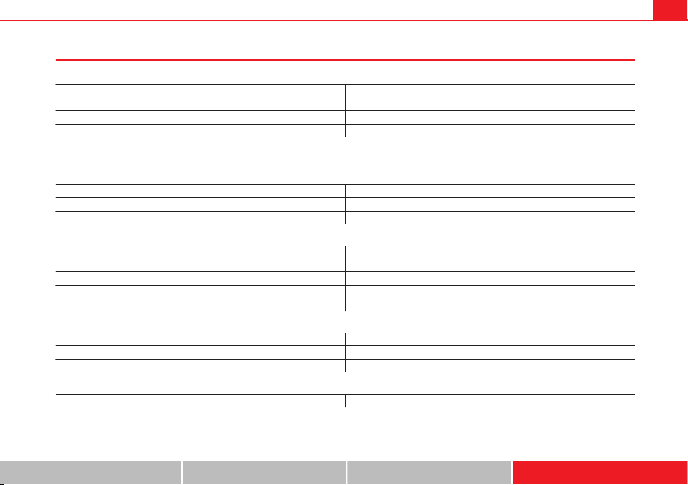
271Technical specifications
Petrol engine 1.4 103 kW (140 PS) Start-Stop
Engine specifications
Power output in kW (PS) rpm 103 (140)/ 5000
Maximum torque in Nm at rpm 250/ 1500-3500
No. of cylinders/capacity in cm
3
4/ 1395
Fuel Super 95 RON
a)
/Normal 91 RON
b)
a)
Research Octane Number = Anti-detonation rating of the petrol.
b)
With a slight power loss
Performance
Maximum speed in km/h (mph) 212 (V&VI)
Acceleration from 0-80 km/h (0-60 mph) in sec. 5,8
Acceleration from 0-100 km/h (0-60 mph) in sec. 8,2
Weights
Gross vehicle weight in kg 1740
Weight in running order (with driver) in kg 1228
Gross front axle weight in kg 910
Gross rear axle weight in kg 880
Permitted roof load in kg 75
Trailer weight
Trailer without brakes in kg 610
Trailer with brakes, gradients up to 8% in kg 1800
Trailer with brakes, gradients up to 12% in kg 1500
Engine oil filling capacity
Approximate engine oil capacity with oil filter change 4.0 litres
Safety First Operating instructions Practical Tips Technical specifications
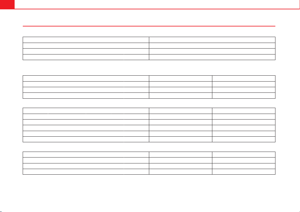
272 Technical specifications
Petrol engine 1.8 132 kW (180 PS) Start-Stop
Engine specifications
Power output in kW (PS) rpm 132 / 5100-6200
Maximum torque in Nm at rpm 250/ 1250-3900
No. of cylinders/capacity in cm
3
4/ 1798
Fuel Super 95 RON
a)
a)
Research Octane Number = Anti-detonation rating of the petrol.
Performance
Manual Automatic
Maximum speed in km/h (mph) 225 (V&VI) 225 (VI)
Acceleration from 0-80 km/h (0-60 mph) in sec. 5,5 5,5
Acceleration from 0-100 km/h (0-60 mph) in sec. 7,5 7,5
Weights
Manual Automatic
Gross vehicle weight in kg 1810 1820
Weight in running order (with driver) in kg 1300 1315
Gross front axle weight in kg 980 1000
Gross rear axle weight in kg 880 870
Permitted roof load in kg 75 75
Trailer weight
Manual Automatic
Trailer without brakes in kg 650 650
Trailer with brakes, gradients up to 8% in kg 1800 1800
Trailer with brakes, gradients up to 12% in kg 1500 1500

273Technical specifications
Diesel engine 1.6 66 kW (90 PS)
Engine specifications
Power output in kW (PS) rpm 66 (90) /2750-4800
Maximum torque in Nm at rpm 230/1400-2750
No. of cylinders/capacity in cm
3
4/1598
Fuel Diesel according to standard EN 590, Min. 51 CN
Performance
Maximum speed in km/h (mph) 179 (IV)
Acceleration from 0-80 km/h (0-60 mph) in sec. 8,2
Acceleration from 0-100 km/h (0-60 mph) in sec. 12,6
Weights
Gross vehicle weight in kg 1820
Weight in running order (with driver) in kg 1281
Gross front axle weight in kg 990
Gross rear axle weight in kg 850
Permitted roof load in kg 75
Trailer weight
Trailer without brakes in kg 640
Trailer with brakes, gradients up to 8% in kg 1700
Trailer with brakes, gradients up to 12% in kg 1400
Safety First Operating instructions Practical Tips Technical specifications
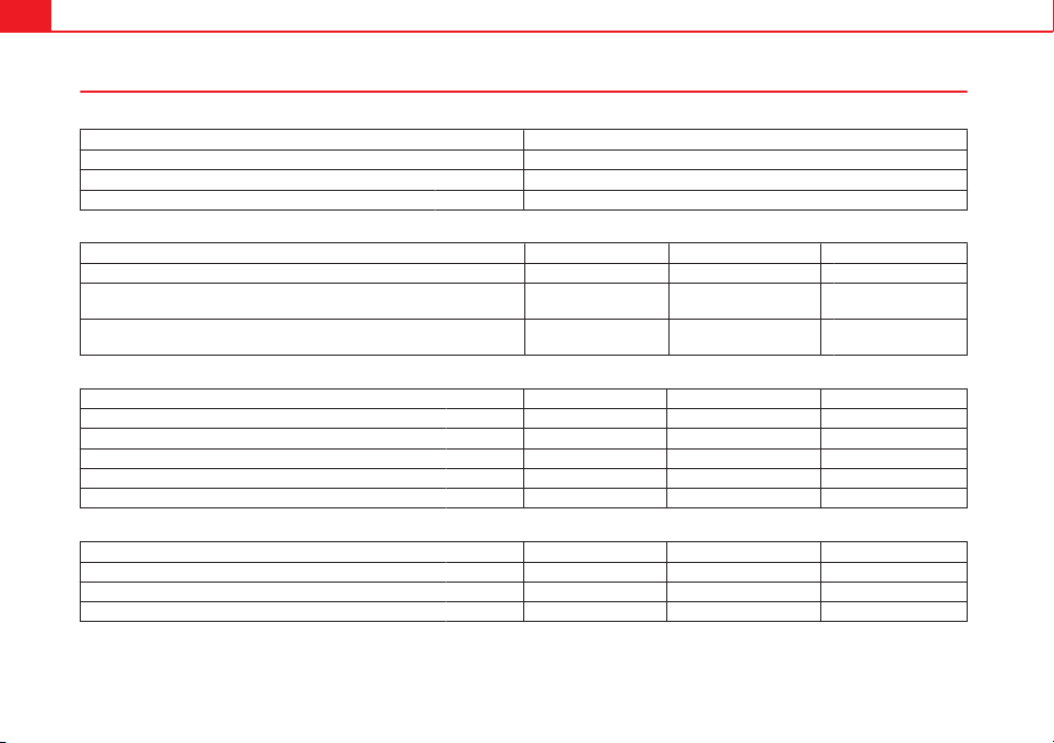
274 Technical specifications
Diesel engine 1.6 77 kW (105 PS)
Engine specifications
Power output in kW (PS) rpm 77 (105) /3000-4000
Maximum torque in Nm at rpm 250/1500-2750
No. of cylinders/capacity in cm
3
4/1598
Fuel Diesel according to standard EN 590, Min. 51 CN
Performance
Manual Start-Stop Automatic
Maximum speed in km/h (mph) 192 (V) 192 (V) 190 (V)
Acceleration from 0-80 km/h (0-60
mph)
in sec. 7,3 7,3 7,1
Acceleration from 0-100 km/h (0-60
mph)
in sec. 10,7 10,7 10,9
Weights
Manual Start-Stop Automatic
Gross vehicle weight in kg 1810 1820 1830
Weight in running order (with driver) in kg 1274 1286 1303
Gross front axle weight in kg 990 990 1020
Gross rear axle weight in kg 870 850 860
Permitted roof load in kg 75 75 75
Trailer weight
Manual Start-Stop Automatic
Trailer without brakes in kg 630 640 650
Trailer with brakes, gradients up to 8% in kg 1800 1800 1800
Trailer with brakes, gradients up to 12% in kg 1500 1500 1500
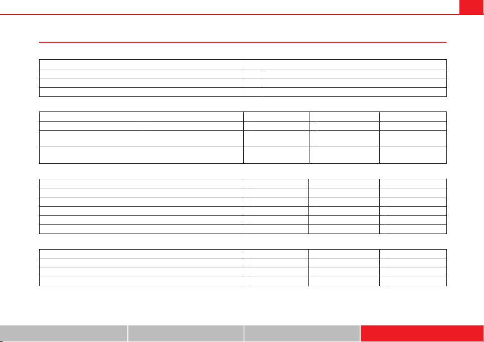
275Technical specifications
Diesel engine 2.0 110 kW (150 PS)
Engine specifications
Power output in kW (PS) rpm 110 (150) /3500-4000
Maximum torque in Nm at rpm 320/1750-3000
No. of cylinders/capacity in cm
3
4/1968
Fuel Diesel according to standard EN 590, Min. 51 CN
Performance
Manual Start-Stop Automatic
Maximum speed in km/h (mph) 211 (V) 211 (V) 210 (V)
Acceleration from 0-80 km/h (0-60
mph)
in sec. 6,2 6,2 6
Acceleration from 0-100 km/h (0-60
mph)
in sec. 8,7 8,7 8,7
Weights
Manual Start-Stop Automatic
Gross vehicle weight in kg 1810 1810 1830
Weight in running order (with driver) in kg 1302 1305 1326
Gross front axle weight in kg 990 1000 1010
Gross rear axle weight in kg 870 880 860
Permitted roof load in kg 75 75 75
Trailer weight
Manual Start-Stop Automatic
Trailer without brakes in kg 650 650 660
Trailer with brakes, gradients up to 8% in kg 1800 1800 1800
Trailer with brakes, gradients up to 12% in kg 1600 1600 1600
Safety First Operating instructions Practical Tips Technical specifications
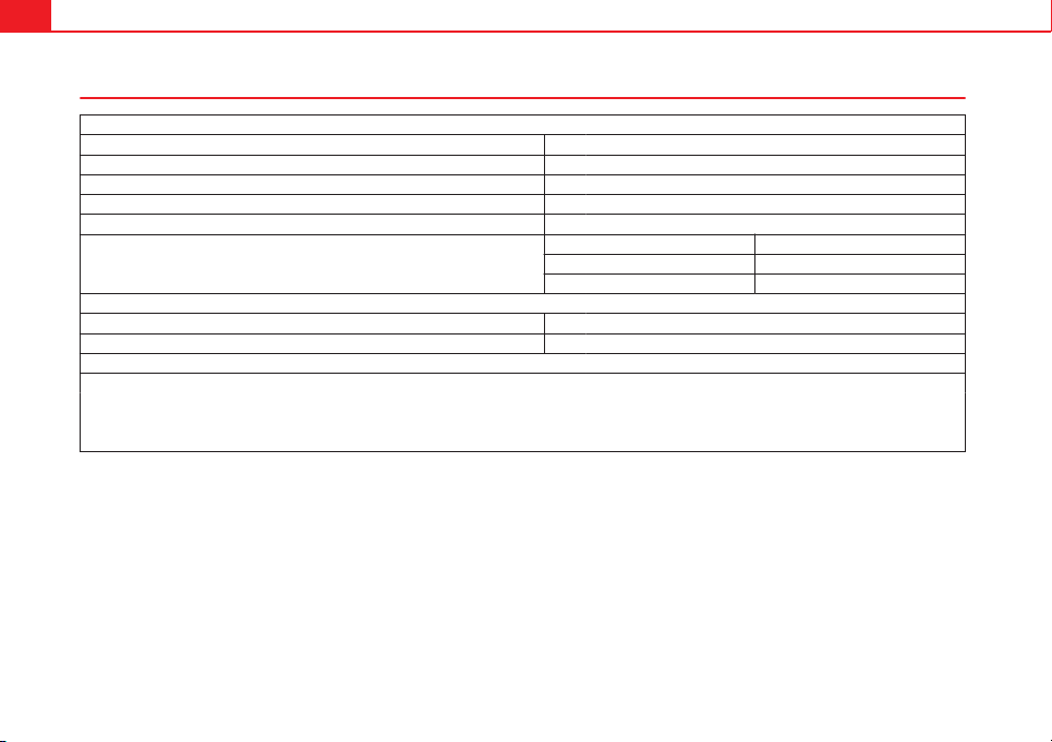
276 Technical specifications
Dimensions and capacities
Dimensions
Length, width 4263 mm/1816 mm
Height at kerb weight 1459 mm
Front and rear projection 853 mm/774 mm
Wheelbase 2636 mm
Turning circle 10.9 m
Track width
a)
Front Rear
1533 mm 1504 mm
1549 mm 1520 mm
Capacities
Fuel tank 50 litres
Windscreen washer fluid container with headlight washer
b)
Tyre pressure
Summer-grade tyres:
The correct tyre pressure can be seen on the sticker on the inside of the tank flap.
Winter tyres:
The pressure of these tyres is the same as the summer tyre pressure plus 0.2 bar.
a)
This data will change depending on the type of wheel rim.
b)
Data not available as this edition goes to print

Index
A
ABS
see Anti-lock brake system . . . . . . . . . . . . 183
Accessories . . . . . . . . . . . . . . . . . . . . . . . . . . . . 129
Acoustic parking aid . . . . . . . . . . . . . . . . . . . . 178
Acoustic warnings
Headlights . . . . . . . . . . . . . . . . . . . . . . . . . 108
Additional electrical appliances (efficiency pro-
gramme) . . . . . . . . . . . . . . . . . . . . . . . . . . . . . 78
Adjusting
the head restraints . . . . . . . . . . . . . . . . . . . 128
Adjusting the head restraint
Front head restraint . . . . . . . . . . . . . . . . . . 127
Airbag . . . . . . . . . . . . . . . . . . . . . . . . . . . . . . . . . 30
Airbag covers . . . . . . . . . . . . . . . . . . . . . . . . . . . 37
Airbag system . . . . . . . . . . . . . . . . . . . . . . . . . . . 30
Control lamp . . . . . . . . . . . . . . . . . . . . . . . . . 33
Curtain airbags . . . . . . . . . . . . . . . . . . . . . . . 42
Differences between front passenger front
airbag systems . . . . . . . . . . . . . . . . . . . . . 32
Front airbags . . . . . . . . . . . . . . . . . . . . . . . . 35
Knee airbag . . . . . . . . . . . . . . . . . . . . . . . . . 38
side airbags . . . . . . . . . . . . . . . . . . . . . . . . . 39
Air pressure (tyres) . . . . . . . . . . . . . . . . . . . . . . 223
Alarm system . . . . . . . . . . . . . . . . . . . . . . . . . . . 93
Alcantara: cleaning . . . . . . . . . . . . . . . . . . . . . 204
Ambient lighting . . . . . . . . . . . . . . . . . . . . . . . 115
Anti-dazzle rear vision mirror . . . . . . . . . . . . . . 123
Anti-dazzle rear vision mirrors
. . . . . . . . . . . . . . . . . . . . . . . . . . . . . . . . . . . 123
Anti-freeze protection
Windscreen washer system . . . . . . . . . . . . 220
Anti-lock brake system . . . . . . . . . . . . . . . . . . . 183
Anti-theft alarm . . . . . . . . . . . . . . . . . . . . . . 86, 93
see also Anti-theft alarm system . . . . . . . . . 86
Anti-theft alarm system
Interior monitoring . . . . . . . . . . . . . . . . . . . . 95
Tow-away protection . . . . . . . . . . . . . . . . . . 95
Anti-theft security system . . . . . . . . . . . . . . 86, 97
Anti-theft wheel bolts . . . . . . . . . . . . . . . . . . . 237
Antifreeze . . . . . . . . . . . . . . . . . . . . . . . . . . . . . 215
Aspects to take into account before starting the
vehicle . . . . . . . . . . . . . . . . . . . . . . . . . . . . . . . . 8
ASR
see Traction control system . . . . . . . . . . . . 183
Assistance systems . . . . . . . . . . . . . . . . . . . . . 164
Cruise control . . . . . . . . . . . . . . . . . . . . . . . 164
Parking aid . . . . . . . . . . . . . . . . . . . . . . . . . 179
Assisted starting . . . . . . . . . . . . . . . . . . . . . . . 241
Assist systems
Tyre monitoring indicator . . . . . . . . . . . . . . 177
Audible warning . . . . . . . . . . . . . . . . . . . . . . . . . 20
Auto Lock (central locking) . . . . . . . . . . . . . . . . 86
Automatic car washes
see Washing . . . . . . . . . . . . . . . . . . . . . . . . 198
Automatic dipped beam control . . . . . . . . . . . 109
Automatic gearbox . . . . . . . . . . . . . . . . . . . . . . 154
Backup programme . . . . . . . . . . . . . . . . . . 162
Downhill speed control . . . . . . . . . . . . . . . 158
Driving tips . . . . . . . . . . . . . . . . . . . . . . . . . 156
Kick-down feature . . . . . . . . . . . . . . . . . . . . 160
Launch Control Programme . . . . . . . . . . . . 160
Manual release of selector lever . . . . . . . . 163
Safety interlock for ignition key . . . . . . . . . 144
Selector lever lock . . . . . . . . . . . . . . . . . . . 155
Selector lever positions . . . . . . . . . . . . . . . 154
Steering wheel with gearshift paddles . . . 159
tiptronic . . . . . . . . . . . . . . . . . . . . . . . 154, 159
B
Balanced (wheels) . . . . . . . . . . . . . . . . . . . . . . 223
Ball coupling . . . . . . . . . . . . . . . . . . . . . . . . . . . 195
Battery . . . . . . . . . . . . . . . . . . . . . . . . . . . . . . . . 217
Assisted starting . . . . . . . . . . . . . . . . . . . . 241
Charge Level . . . . . . . . . . . . . . . . . . . . . . . . 187
Charging . . . . . . . . . . . . . . . . . . . . . . . . . . . 219
Disconnecting/Connecting . . . . . . . . . . . . 217
Power Management . . . . . . . . . . . . . . . . . . 187
Replacement . . . . . . . . . . . . . . . . . . . . . . . . 219
Winter conditions . . . . . . . . . . . . . . . . . . . . 217
Before starting the vehicle . . . . . . . . . . . . . . . . . 8
Biodiesel . . . . . . . . . . . . . . . . . . . . . . . . . . . . . . 207
Bioethanol
see Ethanol (fuel) . . . . . . . . . . . . . . . . . . . . 206
277Index

Brakes . . . . . . . . . . . . . . . . . . . . . . . . . . . . . . . . 185
Brake fluid . . . . . . . . . . . . . . . . . . . . . . . . . 217
Brake servo . . . . . . . . . . . . . . . . . . . . . . . . . 185
New brake pads . . . . . . . . . . . . . . . . . . . . . 185
Braking
Brake assist system . . . . . . . . . . . . . . . . . . 183
Moving off on a hill . . . . . . . . . . . . . . . . . . 148
C
Carbon components: Cleaning . . . . . . . . . . . . 200
Care . . . . . . . . . . . . . . . . . . . . . . . . . . . . . . . . . . 198
Care of vehicle . . . . . . . . . . . . . . . . . . . . . . . . . 198
Care (paint care) . . . . . . . . . . . . . . . . . . . . . . . . 200
Catalytic converter . . . . . . . . . . . . . . . . . . . . . . 190
CD-ROM reader (navigation) . . . . . . . . . . . . . . 130
Central locking
Anti-theft alarm . . . . . . . . . . . . . . . . . . . . . . 93
Central locking switch . . . . . . . . . . . . . . . . . 93
Electric windows . . . . . . . . . . . . . . . . . . . . . 101
Programming . . . . . . . . . . . . . . . . . . . . . . . . 92
Remote control key . . . . . . . . . . . . . . . . . . . . 91
Selective unlocking system . . . . . . . . . . . . . 91
Sliding/tilting sunroof . . . . . . . . . . . . . . . . 101
Central locking system . . . . . . . . . . . . . . . . . . . . 86
Manual locking in an emergency . . . . . . . . 97
Rear lid . . . . . . . . . . . . . . . . . . . . . . . . . . . . . 98
Cetane number (Diesel fuel) . . . . . . . . . . . . . . 207
Changing
Windscreen and rear window wiper blades . .221
Changing a bulb . . . . . . . . . . . . . . . . . . . . . . . . 252
Bulb sizes . . . . . . . . . . . . . . . . . . . . . . . . . . 252
Changing gear
Engaging gears (manual gearbox) . . . . . . 152
Manual gearbox . . . . . . . . . . . . . . . . . . . . . 152
Changing main headlight
main beam . . . . . . . . . . . . . . . . . . . . . . . . . 255
turn signal . . . . . . . . . . . . . . . . . . . . . . . . . . 255
Changing main headlight bulbs
daylight bulb . . . . . . . . . . . . . . . . . . . . . . . 254
Dipped beam . . . . . . . . . . . . . . . . . . . . . . . 254
Changing the battery
of the vehicle key . . . . . . . . . . . . . . . . . . . . . 90
Chassis number . . . . . . . . . . . . . . . . . . . . . . . . 264
Child-proof lock
Electric windows . . . . . . . . . . . . . . . . . . . . . 100
Child safety . . . . . . . . . . . . . . . . . . . . . . . . . . . . . 47
Child seat
Categorisation in groups . . . . . . . . . . . . . . . 49
Group 1 . . . . . . . . . . . . . . . . . . . . . . . . . . . . . 50
Group 2 . . . . . . . . . . . . . . . . . . . . . . . . . . . . . 50
Group 3 . . . . . . . . . . . . . . . . . . . . . . . . . . . . . 50
Groups 0 and 0+ . . . . . . . . . . . . . . . . . . . . . . 49
Safety notes . . . . . . . . . . . . . . . . . . . . . . . . . 47
Securing . . . . . . . . . . . . . . . . . . . . . . . . . . . . 52
Child seats . . . . . . . . . . . . . . . . . . . . . . . . . . . . . 49
ISOFIX system . . . . . . . . . . . . . . . . . . . . . . . . 54
on the front passenger seat . . . . . . . . . . . . . 31
Top Tether system . . . . . . . . . . . . . . . . . 54, 55
Cleaning . . . . . . . . . . . . . . . . . . . . . . . . . . . . . . 198
Alcantara . . . . . . . . . . . . . . . . . . . . . . . . . . . 204
Carbon components . . . . . . . . . . . . . . . . . . 200
Display/Easy Connect control panel . . . . . 202
Exhaust pipe . . . . . . . . . . . . . . . . . . . . . . . . 201
Leather . . . . . . . . . . . . . . . . . . . . . . . . . . . . 203
Plastic parts . . . . . . . . . . . . . . . . . . . . 200, 202
Radio display . . . . . . . . . . . . . . . . . . . . . . . 202
Rims . . . . . . . . . . . . . . . . . . . . . . . . . . . . . . 201
Seat belts . . . . . . . . . . . . . . . . . . . . . . . . . . 205
Trim parts . . . . . . . . . . . . . . . . . . . . . . . . . . 202
Trims . . . . . . . . . . . . . . . . . . . . . . . . . . . . . . 200
Washing the vehicle . . . . . . . . . . . . . . . . . . 198
Windows . . . . . . . . . . . . . . . . . . . . . . . . . . . 201
Windscreen and rear window wiper blades . .221
Cleaning/De-icing the windows . . . . . . . . . . . 201
Cleaning the rims . . . . . . . . . . . . . . . . . . . . . . . 201
Cleaning the upholstery
Natural leather . . . . . . . . . . . . . . . . . . . . . . 203
Closing
Bonnet . . . . . . . . . . . . . . . . . . . . . . . . . . . . 210
Panoramic sliding sunroof . . . . . . . . . . . . . 103
Panoramic sunroof . . . . . . . . . . . . . . . . . . . 103
Windows . . . . . . . . . . . . . . . . . . . . . . . . . . . 100
Clutch (warning lamp) . . . . . . . . . . . . . . . . . . . 162
Coming Home . . . . . . . . . . . . . . . . . . . . . . . . . . 113
Compartments . . . . . . . . . . . . . . . . . . . . . . . . . 129
Consumption (fuel) . . . . . . . . . . . . . . . . . . . . . 264
Control lamp
Airbag system . . . . . . . . . . . . . . . . . . . . . . . . 33
Cruise control . . . . . . . . . . . . . . . . . . . . . . . 164
Tyre monitor indicator warning lamp . . . . 175
Tyre monitoring systems . . . . . . . . . . . . . . 175
Windscreen wiper fluid level . . . . . . . . . . . 117
Control lamps
Lights . . . . . . . . . . . . . . . . . . . . . . . . . . . . . 106
Control of function
Rain sensor . . . . . . . . . . . . . . . . . . . . . . . . . 120
278 Index

Controls and displays (overview) . . . . . . . . . . . 59
Control Units . . . . . . . . . . . . . . . . . . . . . . . . . . . 189
Convenience closing
Panoramic sliding sunroof . . . . . . . . . . . . . 104
Convenience opening
Panoramic sliding sunroof . . . . . . . . . . . . . 104
Convenience opening/closing . . . . . . . . . . . . 101
Cooling system
Checking the coolant . . . . . . . . . . . . . . . . . 216
Coolant temperature gauge . . . . . . . . . . . . . 67
Topping up coolant . . . . . . . . . . . . . . . . . . 216
Cornering lights . . . . . . . . . . . . . . . . . . . . . . . . 109
Correct adjustment of front seat head re-
straints . . . . . . . . . . . . . . . . . . . . . . . . . . . . . . . 14
Correct adjustment of rear seat head restraints
In-use and non-use positions . . . . . . . . . . . 15
Correct sitting position
front passenger . . . . . . . . . . . . . . . . . . . . . . 12
Incorrect sitting position . . . . . . . . . . . . . . . 15
passenger . . . . . . . . . . . . . . . . . . . . . . . . . . . 13
Cruise control . . . . . . . . . . . . . . . . . . . . . . . . . . 164
Control lamp . . . . . . . . . . . . . . . . . . . . . . . . 164
Operation . . . . . . . . . . . . . . . . . . . . . . . . . . 166
Warning lamp . . . . . . . . . . . . . . . . . . . . . . . 164
Cruise control system . . . . . . . . . . . . . . . . . . . . 164
Curtain airbags . . . . . . . . . . . . . . . . . . . . . . . . . . 42
Description . . . . . . . . . . . . . . . . . . . . . . . . . . 42
Operation . . . . . . . . . . . . . . . . . . . . . . . . . . . 42
Safety notes . . . . . . . . . . . . . . . . . . . . . . . . . 43
D
Danger of fitting a child seat on the front pas-
senger seat . . . . . . . . . . . . . . . . . . . . . . . . . . . 31
Data recorder . . . . . . . . . . . . . . . . . . . . . . . . . . 189
Daytime driving light . . . . . . . . . . . . . . . . . . . . 109
DEF (instrument panel) . . . . . . . . . . . . . . . . . . . 67
Depth of tread . . . . . . . . . . . . . . . . . . . . . . . . . . 225
Diagnostic connection . . . . . . . . . . . . . . . . . . . 189
Diesel
Engine oil . . . . . . . . . . . . . . . . . . . . . . . . . . 211
Particulate filter Diesel . . . . . . . . . . . . . . . . 190
Preheating . . . . . . . . . . . . . . . . . . . . . . . . . 144
Digital clock . . . . . . . . . . . . . . . . . . . . . . . . . . . . 61
Dipped beam headlight . . . . . . . . . . . . . . . . . . 108
Direction of rotation (tyres) . . . . . . . . . . . . . . . 239
Disabling the airbag . . . . . . . . . . . . . . . . . . . . . . 44
Display . . . . . . . . . . . . . . . . . . . . . . . . . . . . . 61, 62
Display/Easy Connect control panel: Cleaning . .202
Disposal
Airbags . . . . . . . . . . . . . . . . . . . . . . . . . . . . . 34
Seat belt tensioners . . . . . . . . . . . . . . . . . . . 29
Door/rear lid warning . . . . . . . . . . . . . . . . . . . . . 73
Downhill speed control . . . . . . . . . . . . . . . . . . 158
Drink holders . . . . . . . . . . . . . . . . . . . . . . . . . . 129
Driver
see Correct sitting position . . . . . . . 11, 12, 13
Driver information system
CD/radio display . . . . . . . . . . . . . . . . . . . . . 73
Door/rear lid warning . . . . . . . . . . . . . . . . . . 73
Engine oil temperature display . . . . . . . . . . 77
Operation via the windscreen wiper lever . 73
Outside temperature display . . . . . . . . . . . . 73
Driving
With a trailer . . . . . . . . . . . . . . . . . . . . 194, 195
Driving abroad
Headlights . . . . . . . . . . . . . . . . . . . . . . . . . 112
Driving safety . . . . . . . . . . . . . . . . . . . . . . . . . . . . 8
Driving through water . . . . . . . . . . . . . . . . . . . 190
Dynamic headlight range control . . . . . . . . . . 114
E
E10
see Ethanol (fuel) . . . . . . . . . . . . . . . . . . . . 206
Easy Connect . . . . . . . . . . . . . . . . . . . . . . . . . . . 79
Economic driving . . . . . . . . . . . . . . . . . . . . . . . 191
Efficiency programme
Additional electrical appliances . . . . . . . . . 78
Saving tips . . . . . . . . . . . . . . . . . . . . . . . . . . 78
Electrical accessories
see Power socket . . . . . . . . . . . . . . . . . . . . 129
Electric windows . . . . . . . . . . . . . . . . . . . . . . . . 100
Convenience opening/closing . . . . . . . . . 101
Electro-mechanical steering . . . . . . . . . . . . . . 186
Warning lamp . . . . . . . . . . . . . . . . . . . . . . . 186
Electronic differential lock . . . . . . . . . . . . . . . . 183
Electronic Self-locking . . . . . . . . . . . . . . . . . . . 183
Electronic Stability Control (ESC) . . . . . . . . . . 183
Emergencies . . . . . . . . . . . . . . . . . . . . . . . . . . . 232
Automatic gearbox Backup programme . . 162
Replacing the battery . . . . . . . . . . . . . . . . . 219
Emergency braking warning . . . . . . . . . . . . . . 111
279Index

Emergency locking and unlocking . . . . . . . . . . 96
Engine
Assisted starting . . . . . . . . . . . . . . . . . . . . 241
Preheating . . . . . . . . . . . . . . . . . . . . . . . . . 144
Start-Stop system . . . . . . . . . . . . . . . . . . . . 149
Starting up . . . . . . . . . . . . . . . . . . . . . . . . . 144
Starting up (driver messages with the me-
chanical contact) . . . . . . . . . . . . . . . . . . . 145
Switching off (engine) . . . . . . . . . . . . . . . . 146
Engine compartment
Closing the bonnet . . . . . . . . . . . . . . . . . . . 210
Opening the bonnet . . . . . . . . . . . . . . . . . . 210
Safety notes . . . . . . . . . . . . . . . . . . . . . . . . 209
Engine coolant
G 12 plus-plus . . . . . . . . . . . . . . . . . . . . . . 215
G 13 . . . . . . . . . . . . . . . . . . . . . . . . . . . . . . . 215
Specifications . . . . . . . . . . . . . . . . . . . . . . . 215
Engine oil . . . . . . . . . . . . . . . . . . . . . . . . . . . . . 211
Changing . . . . . . . . . . . . . . . . . . . . . . . . . . 214
Checking oil level . . . . . . . . . . . . . . . . . . . . 212
Consumption . . . . . . . . . . . . . . . . . . . . . . . 212
Engine oil dipstick . . . . . . . . . . . . . . . . . . . 212
Inspection service . . . . . . . . . . . . . . . . . . . 211
Longlife inspection service . . . . . . . . . . . . 211
Oil properties . . . . . . . . . . . . . . . . . . . . . . . 212
Replace . . . . . . . . . . . . . . . . . . . . . . . . . . . . 211
Service intervals . . . . . . . . . . . . . . . . . . . . . 211
Specifications . . . . . . . . . . . . . . . . . . . . . . . 211
Temperature display . . . . . . . . . . . . . . . . . . . 77
Topping up . . . . . . . . . . . . . . . . . . . . . . . . . 213
Environment
Ecological driving . . . . . . . . . . . . . . . . . . . . 191
Environmental friendliness . . . . . . . . . . . . 192
Environmental tip
Leaks . . . . . . . . . . . . . . . . . . . . . . . . . . . . . . 210
Environmental tips
Filling the tank . . . . . . . . . . . . . . . . . . 207, 208
Environment warning . . . . . . . . . . . . . . . . . . . . 179
ESC
Electronic stability control . . . . . . . . . . . . . 183
Mode Sport . . . . . . . . . . . . . . . . . . . . . . . . . 184
Multi-collision brake . . . . . . . . . . . . . . . . . 184
ESC Sport . . . . . . . . . . . . . . . . . . . . . . . . . . . . . 184
Ethanol (fuel) . . . . . . . . . . . . . . . . . . . . . . . . . . 206
Exhaust tail pipe: Cleaning . . . . . . . . . . . . . . . 201
extending the rear lid locking time
see rear lid . . . . . . . . . . . . . . . . . . . . . . . . . . 99
Exterior anti-dazzle rear vision mirrors
. . . . . . . . . . . . . . . . . . . . . . . . . . . . . . . . . . . 123
Exterior lighting
Changing a bulb . . . . . . . . . . . . . . . . . . . . . 252
Exterior mirrors
Adjust . . . . . . . . . . . . . . . . . . . . . . . . . . . . . 122
heated . . . . . . . . . . . . . . . . . . . . . . . . . . . . . 122
Heating . . . . . . . . . . . . . . . . . . . . . . . . . . . . 122
F
Fastening rings . . . . . . . . . . . . . . . . . . . . . . 18, 133
Fault in the gearbox (warning lamp) . . . . . . . . 162
Fault memory . . . . . . . . . . . . . . . . . . . . . . . . . . 189
Faults
Panoramic sliding sunroof . . . . . . . . . . . . . 103
Faults in the gearbox (warning lamps) . . . . . . 162
Faulty bulbs
Changing a bulb . . . . . . . . . . . . . . . . . . . . . 252
Filling the tank . . . . . . . . . . . . . . . . . . . . . . . . . 207
Fuel gauge . . . . . . . . . . . . . . . . . . . . . . . . . . 67
Opening the fuel tank cap . . . . . . . . . . . . . 207
Floor mats . . . . . . . . . . . . . . . . . . . . . . . . . . . . . . 17
Fog light . . . . . . . . . . . . . . . . . . . . . . . . . . . . . . 108
Fold
the seats . . . . . . . . . . . . . . . . . . . . . . . . . . . 132
Fold the back seats . . . . . . . . . . . . . . . . . . . . . 132
Front airbags . . . . . . . . . . . . . . . . . . . . . . . . . . . 35
Description . . . . . . . . . . . . . . . . . . . . . . . . . . 35
Operation . . . . . . . . . . . . . . . . . . . . . . . . . . . 36
Safety notes . . . . . . . . . . . . . . . . . . . . . . . . . 37
Front armrest . . . . . . . . . . . . . . . . . . . . . . . . . . 125
Fuel . . . . . . . . . . . . . . . . . . . . . . . . . . . . . . . . . . 206
Consumption . . . . . . . . . . . . . . . . . . . . . . . 264
Diesel . . . . . . . . . . . . . . . . . . . . . . . . . . . . . 207
Ethanol . . . . . . . . . . . . . . . . . . . . . . . . . . . . 206
Fuel gauge . . . . . . . . . . . . . . . . . . . . . . . . . . 67
Fuel consumption . . . . . . . . . . . . . . . . . . . . . . . 264
Full-LED headlights . . . . . . . . . . . . . . . . . . . . . 252
Fuses
Changing . . . . . . . . . . . . . . . . . . . . . . . . . . 249
Provision . . . . . . . . . . . . . . . . . . . . . . . . . . . 250
G
Gear-change indicator . . . . . . . . . . . . . . . . . . . . 68
Gearbox DSG
see Automatic gearbox . . . . . . . . . . . . . . . 154
Gear recommendation . . . . . . . . . . . . . . . . . . . . 68
280 Index

Gearshift paddles (automatic gearbox) . . . . . 159
General overview of the engine compartment 267
Glass
Cleaning/De-icing . . . . . . . . . . . . . . . . . . . 201
Glove compartment . . . . . . . . . . . . . . . . . . . . . 130
Multiple CD loader . . . . . . . . . . . . . . . . . . . 130
Glove compartment lighting . . . . . . . . . . . . . . 115
H
Handbrake . . . . . . . . . . . . . . . . . . . . . . . . . . . . 147
Warning lamp . . . . . . . . . . . . . . . . . . . . . . . 147
Hazard warning lights . . . . . . . . . . . . . . . . . . . 110
Headlight range control . . . . . . . . . . . . . . . . . . 114
Headlights
Changing a bulb . . . . . . . . . . . . . . . . . . . . . 252
Dipped beam headlights . . . . . . . . . . . . . . 108
Driving abroad . . . . . . . . . . . . . . . . . . . . . . 112
Headlight control . . . . . . . . . . . . . . . . . . . . 108
Headlight washers . . . . . . . . . . . . . . . . . . . 119
Side light . . . . . . . . . . . . . . . . . . . . . . . . . . 108
Heated rear window . . . . . . . . . . . . . . . . . 136, 138
Hill hold assist . . . . . . . . . . . . . . . . . . . . . . . . . 148
see also Hill hold assist . . . . . . . . . . . . . . . 148
Horn . . . . . . . . . . . . . . . . . . . . . . . . . . . . . . . . . . 59
How to jump start description . . . . . . . . . . . . . 242
I
Identification plate . . . . . . . . . . . . . . . . . . . . . . 264
Identifying letters of engine . . . . . . . . . . . . . . 264
Ignition lock . . . . . . . . . . . . . . . . . . . . . . . . . . . 144
Increase capacity
of luggage compartment . . . . . . . . . . . . . . 132
Indicator
Vehicle key . . . . . . . . . . . . . . . . . . . . . . . . . . 89
Inertia mode . . . . . . . . . . . . . . . . . . . . . . . . . . . 161
Information on emissions . . . . . . . . . . . . . . . . 264
Inspection service . . . . . . . . . . . . . . . . . . . . . . 211
Installation of exhaust gas filtration systems
Catalytic converter . . . . . . . . . . . . . . . . . . . 190
Particulate filter Diesel . . . . . . . . . . . . . . . . 190
Instrument cluster . . . . . . . . . . . . . . . . . . . . . . . 61
Instrument panel . . . . . . . . . . . . . . . . . . . . . . . . 61
Display . . . . . . . . . . . . . . . . . . . . . . . . . . 61, 62
Instruments . . . . . . . . . . . . . . . . . . . . . . . . . 61
Lamps . . . . . . . . . . . . . . . . . . . . . . . . . . . . . . 69
Service interval display . . . . . . . . . . . . . . . . 65
Instrument panel lighting . . . . . . . . . . . . . . . . 114
Interior anti-dazzle rear vision mirrors . . . . . . 123
Interior monitoring . . . . . . . . . . . . . . . . . . . . . . . 95
Interior rear vision mirror
see Rear vision mirrors . . . . . . . . . . . . . . . . 123
ISOFIX system . . . . . . . . . . . . . . . . . . . . . . . . . . . 54
J
Jack . . . . . . . . . . . . . . . . . . . . . . . . . . . . . . . . . . 232
Mounting points . . . . . . . . . . . . . . . . . . . . . 238
Jump leads . . . . . . . . . . . . . . . . . . . . . . . . . . . . 241
Jump starting . . . . . . . . . . . . . . . . . . . . . . . . . . 241
K
Key
Driver messages (mechanical contact) . . . 145
Unlocking/Locking . . . . . . . . . . . . . . . . . . . . 91
Keys
Assigning a key . . . . . . . . . . . . . . . . . . . . . . 88
Changing the battery (vehicle key) . . . . . . . 90
Indicator . . . . . . . . . . . . . . . . . . . . . . . . . . . . 89
Locking/Unlocking . . . . . . . . . . . . . . . . . . . . 97
Remote control . . . . . . . . . . . . . . . . . . . . . . . 88
Spare key . . . . . . . . . . . . . . . . . . . . . . . . . . . 88
Vehicle key . . . . . . . . . . . . . . . . . . . . . . . . . . 88
Kick-down
Manual gearbox . . . . . . . . . . . . . . . . . . . . . 146
Kick-down feature
Automatic gearbox . . . . . . . . . . . . . . . . . . . 160
Knee airbag
See "Airbag system" . . . . . . . . . . . . . . . . . . 38
L
Lamps
Audible warnings . . . . . . . . . . . . . . . . . . . . . 69
Control lamps . . . . . . . . . . . . . . . . . . . . . . . . 69
Warning lamps . . . . . . . . . . . . . . . . . . . . . . . 69
Lane Assist . . . . . . . . . . . . . . . . . . . . . . . . . . . . 168
Cleaning the camera area . . . . . . . . . . . . . 199
Lane Assist system
see Lane Assist . . . . . . . . . . . . . . . . . . . . . . 168
Launch Control Programme (automatic gear-
box) . . . . . . . . . . . . . . . . . . . . . . . . . . . . . . . . 160
281Index

Leather Care
Natural leather . . . . . . . . . . . . . . . . . . . . . . 203
Leather: Care . . . . . . . . . . . . . . . . . . . . . . . . . . 203
Leaving Home . . . . . . . . . . . . . . . . . . . . . . . . . . 113
Lighting
Changing a bulb . . . . . . . . . . . . . . . . . . . . . 252
Lights . . . . . . . . . . . . . . . . . . . . . . . . . . . . . . . . 106
Acoustic warnings . . . . . . . . . . . . . . . . . . . 108
AUTO . . . . . . . . . . . . . . . . . . . . . . . . . . . . . . 109
Changing a bulb . . . . . . . . . . . . . . . . . . . . . 252
Coming home . . . . . . . . . . . . . . . . . . . . . . . 113
Control lamps . . . . . . . . . . . . . . . . . . . . . . . 106
Controls lighting . . . . . . . . . . . . . . . . . . . . . 114
Cornering lights . . . . . . . . . . . . . . . . . . . . . 109
Daytime driving light . . . . . . . . . . . . . . . . . 109
Fog light . . . . . . . . . . . . . . . . . . . . . . . . . . . 108
Functions . . . . . . . . . . . . . . . . . . . . . . . . . . 109
Headlight range control . . . . . . . . . . . . . . . 114
Instrument lighting . . . . . . . . . . . . . . . . . . 114
Interior lights . . . . . . . . . . . . . . . . . . . . . . . 115
Leaving home . . . . . . . . . . . . . . . . . . . . . . . 113
Main beam lever . . . . . . . . . . . . . . . . . . . . . 107
Motorway lights . . . . . . . . . . . . . . . . . . . . . 109
Parking light . . . . . . . . . . . . . . . . . . . . . . . . 109
Reading lights . . . . . . . . . . . . . . . . . . . . . . 115
Turn signal lever . . . . . . . . . . . . . . . . . . . . . 107
Load compartment in the luggage compart-
ment
see Loading the luggage compartment . . . 17
Loading the luggage compartment . . . . . . . . . . 17
Locking/Unlocking
In the lock cylinder . . . . . . . . . . . . . . . . . . . . 97
With the central locking switch . . . . . . . . . . 93
Longlife inspection service . . . . . . . . . . . . . . . 211
Luggage carrier . . . . . . . . . . . . . . . . . . . . . . . . . 131
Luggage compartment . . . . . . . . . . . . . . . . . . . 131
Cover . . . . . . . . . . . . . . . . . . . . . . . . . . . . . . 132
Fastening rings . . . . . . . . . . . . . . . . . . . . . . 133
Luggage compartment lighting . . . . . . . . . 115
see also Loading the luggage compartment . .17
Lumbar support . . . . . . . . . . . . . . . . . . . . . . . . 125
M
Main beam assist . . . . . . . . . . . . . . . . . . . . . . . 111
Main beam headlight . . . . . . . . . . . . . . . . . . . . 108
Main beam lever . . . . . . . . . . . . . . . . . . . . . . . . 107
Maintenance
Airbags . . . . . . . . . . . . . . . . . . . . . . . . . . . . . 34
Manual gearbox . . . . . . . . . . . . . . . . . . . . . . . . 152
Kick-down . . . . . . . . . . . . . . . . . . . . . . . . . . 146
Manual locking of passenger door in an emer-
gency . . . . . . . . . . . . . . . . . . . . . . . . . . . . . . . . 97
Manual operation
Selector lever . . . . . . . . . . . . . . . . . . . . . . . 163
Manual operation in an emergency
Passenger door . . . . . . . . . . . . . . . . . . . . . . 97
Rear lid . . . . . . . . . . . . . . . . . . . . . . . . . . . . . 99
Mobile phones . . . . . . . . . . . . . . . . . . . . . . . . . 230
Modifications (technical) . . . . . . . . . . . . . . . . . 230
Motorway lights . . . . . . . . . . . . . . . . . . . . . . . . 109
Mounting pin (tyre change) . . . . . . . . . . . . . . . 232
Mounting points (jack) . . . . . . . . . . . . . . . . . . . 238
Moving off
Hill hold assist . . . . . . . . . . . . . . . . . . . . . . 148
Multi-collision Brake . . . . . . . . . . . . . . . . . . . . 184
Multiple CD loader . . . . . . . . . . . . . . . . . . . . . . 130
N
Navigation system
CD-ROM Reade . . . . . . . . . . . . . . . . . . . . . . 130
Note regarding the environment
Roof carrier . . . . . . . . . . . . . . . . . . . . . . . . . 131
Number of colour . . . . . . . . . . . . . . . . . . . . . . . 264
Number of seats . . . . . . . . . . . . . . . . . . . . . . . . . 19
O
Object holders . . . . . . . . . . . . . . . . . . . . . . . . . 129
Octane rating (petrol) . . . . . . . . . . . . . . . . . . . . 206
Odometer . . . . . . . . . . . . . . . . . . . . . . . . . . . . . . 61
Oil change . . . . . . . . . . . . . . . . . . . . . . . . . . . . . 214
Oil properties . . . . . . . . . . . . . . . . . . . . . . . . . . 212
One-touch opening and closing
Electric windows . . . . . . . . . . . . . . . . . . . . . 101
Opening . . . . . . . . . . . . . . . . . . . . . . . . . . . . . . . 86
Bonnet . . . . . . . . . . . . . . . . . . . . . . . . . . . . 210
Fuel tank flap . . . . . . . . . . . . . . . . . . . . . . . 207
Panoramic sliding sunroof . . . . . . . . . . . . . 103
Panoramic sunroof . . . . . . . . . . . . . . . . . . . 103
Rear lid . . . . . . . . . . . . . . . . . . . . . . . . . . . . . 98
Windows . . . . . . . . . . . . . . . . . . . . . . . . . . . 100
Opening/Closing
In the lock cylinder . . . . . . . . . . . . . . . . . . . . 97
With remote control . . . . . . . . . . . . . . . . . . . 91
With the central locking switch . . . . . . . . . . 93
282 Index

Outside temperature . . . . . . . . . . . . . . . . . . . . . 64
Outside temperature display . . . . . . . . . . . . . . . 73
Overview
Turn signal and main beam lever . . . . . . . 107
Overview (controls and displays) . . . . . . . . . . . 59
P
Paint code . . . . . . . . . . . . . . . . . . . . . . . . . . . . . 264
Paint damage . . . . . . . . . . . . . . . . . . . . . . . . . . 200
Panoramic sliding sunroof . . . . . . . . . . . . . . . . 103
Closing . . . . . . . . . . . . . . . . . . . . . . . . . . . . 103
Convenience closing . . . . . . . . . . . . . . . . . 104
Convenience opening . . . . . . . . . . . . . . . . 104
Fault . . . . . . . . . . . . . . . . . . . . . . . . . . . . . . 103
Opening . . . . . . . . . . . . . . . . . . . . . . . . . . . 103
Roll-back function . . . . . . . . . . . . . . . . . . . 104
Parking . . . . . . . . . . . . . . . . . . . . . . . . . . . . . . . 147
Parking aid
Adjusting the display/audible warnings . 181
Environment warning . . . . . . . . . . . . . . . . . 179
Fault . . . . . . . . . . . . . . . . . . . . . . . . . . . . . . 181
Plus parking aid . . . . . . . . . . . . . . . . . . . . . 179
Rear parking aid . . . . . . . . . . . . . . . . . . . . . 179
Sensors/Camera: cleaning . . . . . . . . . . . . 199
Towing bracket . . . . . . . . . . . . . . . . . . . . . . 182
Parking aid system
see Parking aid . . . . . . . . . . . . . . . . . . . . . . 179
Parking light . . . . . . . . . . . . . . . . . . . . . . . . . . . 109
Parking (automatic gearbox) . . . . . . . . . . 156, 157
Particulate filter (Diesel) . . . . . . . . . . . . . . . . . 190
Passenger
see Correct sitting position . . . . . . . 11, 12, 13
Pedals . . . . . . . . . . . . . . . . . . . . . . . . . . . . . . . . . 16
Physical principles of a frontal collision . . . . . . 21
Plastic parts: Cleaning . . . . . . . . . . . . . . . 200, 202
Polishing . . . . . . . . . . . . . . . . . . . . . . . . . . . . . . 200
Power Management . . . . . . . . . . . . . . . . . . . . . 187
Power socket . . . . . . . . . . . . . . . . . . . . . . . . . . 129
Preheating . . . . . . . . . . . . . . . . . . . . . . . . . . . . 144
Pressure (tyres) . . . . . . . . . . . . . . . . . . . . . . . . . 223
R
Racks . . . . . . . . . . . . . . . . . . . . . . . . . . . . . . . . . 130
Radio display: cleaning . . . . . . . . . . . . . . . . . . 202
Radio transmitters . . . . . . . . . . . . . . . . . . . . . . 230
Rain sensor . . . . . . . . . . . . . . . . . . . . . . . . . . . . 120
Control of function . . . . . . . . . . . . . . . . . . . 120
Rear lid
automatic locking . . . . . . . . . . . . . . . . . . . . . 99
Central locking system . . . . . . . . . . . . . . . . . 98
Manual release in an emergency . . . . . . . . 99
Rear lights
Changing a bulb . . . . . . . . . . . . . . . . . . . . . 252
Rear vision mirror . . . . . . . . . . . . . . . . . . . . . . . 122
Rear vision mirrors
Adjusting the exterior mirrors . . . . . . . . . . 122
see also Rear vision mirrors . . . . . . . . . . . . 123
Reflective vests . . . . . . . . . . . . . . . . . . . . . . . . . 232
Remote control
See "Keys" . . . . . . . . . . . . . . . . . . . . . . . . . . 88
Remote control key
Unlocking/Locking . . . . . . . . . . . . . . . . . . . . 91
Remove the wheel cover . . . . . . . . . . . . . . . . . 236
Removing the head restraint
. . . . . . . . . . . . . . . . . . . . . . . . . . . . . . . . . . . 128
Repairs . . . . . . . . . . . . . . . . . . . . . . . . . . . . . . . 230
Airbags . . . . . . . . . . . . . . . . . . . . . . . . . . . . . 34
Replacement parts . . . . . . . . . . . . . . . . . . . . . . 230
Reservoir capacity
Windscreen washer water reservoir . . . . . 122
Reset button (trip recorder) . . . . . . . . . . . . . . . . 67
Reset the trip recorder to zero . . . . . . . . . . . . . . 67
Retrofitting a towing bracket . . . . . . . . . . . . . . 196
Rev counter . . . . . . . . . . . . . . . . . . . . . . . . . . 61, 66
Reverse gear (automatic gearbox) . . . . . . . . . 154
Rims
Cleaning . . . . . . . . . . . . . . . . . . . . . . . . . . . 201
RME (fuel) . . . . . . . . . . . . . . . . . . . . . . . . . . . . . 207
Roll-back function
Panoramic sliding sunroof . . . . . . . . . . . . . 104
Windows . . . . . . . . . . . . . . . . . . . . . . . . . . . 102
Roof carrier (roof load) . . . . . . . . . . . . . . . . . . . 131
Running in
New brake pads . . . . . . . . . . . . . . . . . . . . . 185
New engine . . . . . . . . . . . . . . . . . . . . . . . . . 190
New tyres . . . . . . . . . . . . . . . . . . . . . . . . . . 223
S
Safe driving . . . . . . . . . . . . . . . . . . . . . . . . . . . . . 7
Safelock
see Anti-theft security system . . . . . . . . . . . 86
283Index

Safety . . . . . . . . . . . . . . . . . . . . . . . . . . . . . . . . . . 8
child safety . . . . . . . . . . . . . . . . . . . . . . . . . . 47
child seats . . . . . . . . . . . . . . . . . . . . . . . . . . 47
Safety equipment . . . . . . . . . . . . . . . . . . . . . . . . . 7
Safety first . . . . . . . . . . . . . . . . . . . . . . . . . . . . . . . 7
Safety interlock for ignition key . . . . . . . . . . . . 144
Safety notes
Airbags . . . . . . . . . . . . . . . . . . . . . . . . . . . . . 34
Curtain airbags . . . . . . . . . . . . . . . . . . . . . . . 43
Front airbags . . . . . . . . . . . . . . . . . . . . . . . . 37
Seat belt tensioners . . . . . . . . . . . . . . . . . . . 29
Side airbags . . . . . . . . . . . . . . . . . . . . . . . . . 41
Using child seats . . . . . . . . . . . . . . . . . . . . . 47
Using seat belts . . . . . . . . . . . . . . . . . . . . . . 23
Saving fuel
Conscientious driving . . . . . . . . . . . . . . . . 191
Inertia mode . . . . . . . . . . . . . . . . . . . . . . . . 161
Saving tips (efficiency programme) . . . . . . . . . 78
Seat
adjustment . . . . . . . . . . . . . . . . . . . . . . . . . 125
Seat adjuster . . . . . . . . . . . . . . . . . . . . . . . . . . . 10
Seat belt control lamp . . . . . . . . . . . . . . . . . . . . 19
Seat belt position
Pregnant women . . . . . . . . . . . . . . . . . . . . . 27
Seat belts . . . . . . . . . . . . . . . . . . . . . . . . . . . 26
Seat belt protection . . . . . . . . . . . . . . . . . . . . . . 23
Seat belt release . . . . . . . . . . . . . . . . . . . . . . . . 27
Seat belts . . . . . . . . . . . . . . . . . . . . . . . . . . . . . . 19
Adjustment . . . . . . . . . . . . . . . . . . . . . . . . . . 25
Cleaning . . . . . . . . . . . . . . . . . . . . . . . . . . . 205
control lamp . . . . . . . . . . . . . . . . . . . . . . . . . 19
Incorrectly fastened . . . . . . . . . . . . . . . . . . . 28
Not worn . . . . . . . . . . . . . . . . . . . . . . . . . . . . 22
Safety notes . . . . . . . . . . . . . . . . . . . . . . . . . 23
Seat belt tensioners . . . . . . . . . . . . . . . . . . . . . . 28
SEAT Drive Mode . . . . . . . . . . . . . . . . . . . . . . . 171
Selective unlocking system . . . . . . . . . . . . . . . . 91
Selector lever
Automatic gearbox . . . . . . . . . . . . . . . . . . . 154
Function fault . . . . . . . . . . . . . . . . . . . . . . . 155
Selector lever (automatic gearbox)
Manual release . . . . . . . . . . . . . . . . . . . . . . 163
Service interval display . . . . . . . . . . . . . . . . . . . 65
Service intervals . . . . . . . . . . . . . . . . . . . . . . . . 211
Service notification: read . . . . . . . . . . . . . . . . . . 66
Setting
Headlight range . . . . . . . . . . . . . . . . . . . . . 114
Side airbags . . . . . . . . . . . . . . . . . . . . . . . . . . . . 39
Description . . . . . . . . . . . . . . . . . . . . . . . . . . 39
Operation . . . . . . . . . . . . . . . . . . . . . . . . . . . 40
Safety notes . . . . . . . . . . . . . . . . . . . . . . . . . 41
side assist
Cleaning the sensors . . . . . . . . . . . . . . . . . 199
Side light . . . . . . . . . . . . . . . . . . . . . . . . . . . . . 108
Sitting position
driver . . . . . . . . . . . . . . . . . . . . . . . . . . . . . . . 11
Sitting position for vehicle occupants . . . . . . . 10
Sliding/tilting sunroof
Convenience opening/closing . . . . . . . . . 101
Snow chains . . . . . . . . . . . . . . . . . . . . . . . 229, 266
Spanner symbol . . . . . . . . . . . . . . . . . . . . . . . . . 65
Special features
Windscreen wipers . . . . . . . . . . . . . . . . . . . 118
Speedometer . . . . . . . . . . . . . . . . . . . . . . . . . . . 73
Speed warning function . . . . . . . . . . . . . . . . . . 149
Start-Stop system . . . . . . . . . . . . . . . . . . . . . . . 149
Driver messages . . . . . . . . . . . . . . . . . . . . . 152
Stop/Start the engine . . . . . . . . . . . . . . . . 150
Switching on/off . . . . . . . . . . . . . . . . . . . . . 152
The engine does not switch off . . . . . . . . . 151
The engine starts by itself . . . . . . . . . . . . . 151
Warning lamps . . . . . . . . . . . . . . . . . . . . . . 150
Starting up (engine) . . . . . . . . . . . . . . . . . . . . . 144
Steering
Electro-mechanical steering . . . . . . . . . . . 186
Engage the steering lock (ignition
key) . . . . . . . . . . . . . . . . . . . . . . . . . . 144, 146
Steering wheel
Gearshift paddles (automatic gearbox) . . 159
Setting . . . . . . . . . . . . . . . . . . . . . . . . . . . . 143
Storage compartment . . . . . . . . . . . . . . . . . . . 130
Storage compartments
Glove compartment lighting . . . . . . . . . . . 115
Sun visor . . . . . . . . . . . . . . . . . . . . . . . . . . . . . . 116
Switch
Hazard warning lights . . . . . . . . . . . . . . . . 110
Switching ignition on/off . . . . . . . . . . . . . . . . . 144
Switching off using inertia . . . . . . . . . . . . . . . . 191
Switching off (engine)
With the key . . . . . . . . . . . . . . . . . . . . . . . . 146
Symbols
See "Lamps" . . . . . . . . . . . . . . . . . . . . . . . . . 69
System
Automatic dipped beam control . . . . . . . . 109
System Easy Connect . . . . . . . . . . . . . . . . . . . . . 79
284 Index

Systems
Cruise control . . . . . . . . . . . . . . . . . . . . . . . 164
Tiredness detection . . . . . . . . . . . . . . . . . . 173
Tyre monitoring indicator . . . . . . . . . . . . . . 177
Tyre monitoring systems . . . . . . . . . . . . . . 175
T
Technical data
Reservoir capacity . . . . . . . . . . . . . . . . . . . 122
Technical modifications . . . . . . . . . . . . . . . . . . 230
Technical specifications . . . . . . . . . . . . . . . . . . 263
Temperature display
Engine oil . . . . . . . . . . . . . . . . . . . . . . . . . . . 77
Outside temperature . . . . . . . . . . . . . . . 64, 73
The danger of not using the seat belt . . . . . . . . 22
Tightening torque of wheel bolts . . . . . . . . . . 266
tiptronic (automatic gearbox) . . . . . . . . . . . . . 154
Tiptronic (automatic gearbox) . . . . . . . . . . . . . 159
Tiredness detection . . . . . . . . . . . . . . . . . . . . . 173
Tools . . . . . . . . . . . . . . . . . . . . . . . . . . . . . . . . . 232
Top Tether system . . . . . . . . . . . . . . . . . . . . 54, 55
Tow-away protection . . . . . . . . . . . . . . . . . . . . . 95
Tow-starting the engine . . . . . . . . . . . . . . . . . . 244
Tow-starting the vehicle . . . . . . . . . . . . . . . . . . 244
Towing
Retrofitting a towing bracket . . . . . . . . . . . 196
Towing a trailer . . . . . . . . . . . . . . . . . . . . . 194, 265
Towing bracket . . . . . . . . . . . . . . . . . . . . . . . . . 195
Towline anchorage . . . . . . . . . . . . . . . . . . . . . . 232
Traction control system . . . . . . . . . . . . . . . . . . 183
Trailer
Parking aid . . . . . . . . . . . . . . . . . . . . . . . . . 182
Trailer weights . . . . . . . . . . . . . . . . . . . . . . . . . 265
Transporting children . . . . . . . . . . . . . . . . . . . . . 47
Trim parts: cleaning . . . . . . . . . . . . . . . . . . . . . 202
Trims: Cleaning . . . . . . . . . . . . . . . . . . . . . . . . . 200
Trip recorder . . . . . . . . . . . . . . . . . . . . . . . . . 61, 67
Turning off the lights . . . . . . . . . . . . . . . . . . . . 108
Turning on the headlights . . . . . . . . . . . . . . . . 108
Turn signal convenience function . . . . . . . . . . 107
Turn signal lever . . . . . . . . . . . . . . . . . . . . . . . . 107
Tyre
Tyre pressure . . . . . . . . . . . . . . . . . . . . . . . 223
Useful life . . . . . . . . . . . . . . . . . . . . . . . . . . 223
Tyre Mobility System (Tyre repair kit) . . . . . . . 233
Tyre monitoring indicator . . . . . . . . . . . . . . . . . 177
Tyre monitoring system . . . . . . . . . . . . . . . . . . 175
Tyre monitoring systems
Control lamp . . . . . . . . . . . . . . . . . . . . . . . . 175
Tyre monitoring indicator . . . . . . . . . . . . . . 177
Tyre pressures . . . . . . . . . . . . . . . . . . . . . . . . . . 266
Tyre repair kit . . . . . . . . . . . . . . . . . . . . . . . . . . 232
Tyres
Accessories . . . . . . . . . . . . . . . . . . . . . . . . . 223
Changing . . . . . . . . . . . . . . . . . . . . . . . . . . 235
Indications of wear . . . . . . . . . . . . . . . . . . . 225
Repair kit . . . . . . . . . . . . . . . . . . . . . . . 232, 233
With compulsory direction of rotation . . . 239
U
Unlocking/Locking
With remote control . . . . . . . . . . . . . . . . . . . 91
With the central locking switch . . . . . . . . . . 93
Upholstery: Cleaning
Alcantara . . . . . . . . . . . . . . . . . . . . . . . . . . . 204
Fabrics . . . . . . . . . . . . . . . . . . . . . . . . . . . . . 202
V
Vehicle
Identification number . . . . . . . . . . . . . . . . 264
Raising . . . . . . . . . . . . . . . . . . . . . . . . . . . . 238
Sticker . . . . . . . . . . . . . . . . . . . . . . . . . . . . . 264
Vehicle identification data . . . . . . . . . . . . . 264
Vehicle battery
Disconnect . . . . . . . . . . . . . . . . . . . . . . . . . . 66
Vehicle care
Changing wiper blades of the windscreen
and rear window . . . . . . . . . . . . . . . . . . . 221
Cleaning windscreen and rear window wip-
er blades . . . . . . . . . . . . . . . . . . . . . . . . . 221
Service position . . . . . . . . . . . . . . . . . . . . . 119
Vehicle interior monitoring and anti-tow system
Activation . . . . . . . . . . . . . . . . . . . . . . . . . . . 94
Vehicle key
Synchronising . . . . . . . . . . . . . . . . . . . . . . . . 90
Vehicle tools . . . . . . . . . . . . . . . . . . . . . . . . . . . 232
Ventilation slits . . . . . . . . . . . . . . . . . . . . . . . . . 18
285Index

W
Warning lamp
Cruise control . . . . . . . . . . . . . . . . . . . . . . . 164
Washing
Care of the vehicle exterior . . . . . . . . . . . . 198
Wearing suitable shoes . . . . . . . . . . . . . . . . . . . 16
Wheel
changing . . . . . . . . . . . . . . . . . . . . . . . . . . . 225
Wheel bolts . . . . . . . . . . . . . . . . . . . . . . . . 227, 266
Anti-theft . . . . . . . . . . . . . . . . . . . . . . . . . . . 237
Loosening . . . . . . . . . . . . . . . . . . . . . . . . . . 237
Removing the cap . . . . . . . . . . . . . . . . . . . . 236
Wheel brace . . . . . . . . . . . . . . . . . . . . . . . . . . . 232
Wheel cover (wheel bolts): removing . . . . . . . 236
Wheels . . . . . . . . . . . . . . . . . . . . . . . . . . . 223, 266
Changing . . . . . . . . . . . . . . . . . . . . . . 235, 239
Why assume the correct sitting position? . . . . . 30
Why should head restraints be correctly adjus-
ted? . . . . . . . . . . . . . . . . . . . . . . . . . . . . . . . . . 14
Why wear seat belts? . . . . . . . . . . . . . . . 19, 21, 30
Windows
Electric windows . . . . . . . . . . . . . . . . . . . . . 100
Windscreen washer . . . . . . . . . . . . . . . . . . . . . 116
Windscreen washer system . . . . . . . . . . . . . . . 220
Windscreen washer water
Checking . . . . . . . . . . . . . . . . . . . . . . . . . . . 121
Topping up . . . . . . . . . . . . . . . . . . . . . . . . . 121
Windscreen wiper . . . . . . . . . . . . . . . . . . . . . . . 116
Window wiper lever . . . . . . . . . . . . . . . . . . 118
Windscreen wiper fluid
Control lamp . . . . . . . . . . . . . . . . . . . . . . . . 117
Windscreen wipers
Functions . . . . . . . . . . . . . . . . . . . . . . . . . . 119
Headlight washer system . . . . . . . . . . . . . 119
Heated windscreen washer jets . . . . . . . . 119
Lifting the wiper blades . . . . . . . . . . . . . . . 119
Rain sensor . . . . . . . . . . . . . . . . . . . . . . . . . 120
Replacing the wiper blades . . . . . . . . . . . . 119
Service position . . . . . . . . . . . . . . . . . . . . . 119
Special features . . . . . . . . . . . . . . . . . . . . . 118
Windscreen wipers service position . . . . . . . . 119
Winter conditions
Battery . . . . . . . . . . . . . . . . . . . . . . . . . . . . . 217
Care of vehicle . . . . . . . . . . . . . . . . . . . . . . 198
De-icing the glass . . . . . . . . . . . . . . . . . . . . 201
Diesel . . . . . . . . . . . . . . . . . . . . . . . . . . . . . 207
Snow chains . . . . . . . . . . . . . . . . . . . . . . . . 229
Tyres . . . . . . . . . . . . . . . . . . . . . . . . . . . . . . 227
Windscreen washer system . . . . . . . . . . . . 220
Winter operation
Headlight washers . . . . . . . . . . . . . . . . . . . 119
Heated windscreen washer jets . . . . . . . . 119
Salt on the roads . . . . . . . . . . . . . . . . . . . . 121
Winter tyres . . . . . . . . . . . . . . . . . . . . . . . . . . . . 227
286 Index

1.
2.
3.
4.
5. 6. 7.
SEAT S.A. is permanently concerned about continuous development of its types and models. For this reason we ask you to under-
stand, that at any given time, changes regarding shape, equipment and technique may take place on the car delivered. For this reason
no right at all may derive based on the data, drawings and descriptions in this current handbook.
All texts, illustrations and standards in this handbook are based on the status of information at the time of printing. Except for error
or omission, the information included in the current handbook is valid as of the date of closing print.
Re-printing, copying or translating, whether total or partial is not allowed unless SEAT allows it in written form.
SEAT reserves all rights in accordance with the “Copyright” Act.
All rights on changes are reserved.
❀
This paper has been manufactured using bleached non-chlorine cellulose.
© SEAT S.A. - Reprint: 15.06.12
SEAT recommends Castrol
Portada_PM_LEON_interior.indd 3 23/08/12 15:47
5F4012003B
Inglés 5F4012003B (06.12) (GT9)
LEON
Owner’s manual
LEON Inglés (06.12)