SECTION
PAGE
Warranty
Safety Instructions
Operation
Cleaning
Parts Included With Hood
Parts Not Included With Hood ..
Tools Needed .
Equivalent Duct Length Chart ..
Prepare The Hood Location
Prepare The Hood .
7. 8
Connect The Wiring Install The Hood .
Service Parts
If within 1 year from the date of installation. any part of this range hood fails to function properly due to a defect in ma terial or workmanship.
Sears wil! repair the part or furnish and install a new part. free of charge.
FULL 30DAY WARRANTY ON FiNiSH ON PAINTED OR BRIGHT METAL PARTS
If within 30 days from the date of installation. the finish on any painted or bright metal parts of this range hood is de fective in material or workmanship.
Sears will furnish and install a new part. free of charge.
WARRANTY SERVICE tS AVAILABLE BY CONTACTING THE NEAREST SEARS SEVICE CENTER/DEPARTMENT iN THE UNITED STATES.
This warranty applies only while this product is in use in the United States. This warranty gives you specific legal rights and you may have other rights which vary from state to state.
Sears.
Roebuck and Co. Dept 817WA. Roffman Estates.
WARNING HNTENDEDFOR DOMESTHCC00KHNGONLY.A
TO REDUCE THE RiSK OF FIRE. ELECTRIC SHOCK. OR iNJURY TO PERSONS.
OBSERVE THE FOLLOWING:
Use this unit only in the manner intended by the manufac turer. If you have questions. contact the manufacturer at the address listed in the warranty.
Before servicing or cleaning unit. switch power off at service panel and lock the service disconnecting means to prevent power from being switched on accidentally.
When the service disconnecting means cannot be locked. securely fasten a prominent warning device. such as a tag. to the service panel.
Installation work and electrical wiring must be done by a qualified person(s)in accordance with all applicable codes and standards. including fire-rated codes and standards.
4. Sufficient air is needed for proper combustion and exhausting of gases through the flue (chimney) of fuel burning equipment to prevent backdrafting.
Follow the heating equipment manufacturer's guideline and safety standards such as those published by the National Fire Protection Association (NFPA). and the American Society for Heating.
Refrigeration and Air Conditioning Engineers (ASHRAE). and the local code authorities.
5. When cutting or drilling into wail or ceiling. do not damage electrical wiring and other hidden utilities.
6. To reduce the risk of fire or electric shock. do not use this range hood with an additional speed control device.
Ducted fans must always be vented to the outdoors.
8. To reduce the risk of fire. use only metal ductwork.
Use with improved cord-connection kit only.
10.This unit must be grounded.
TO REDUCE THE RiSK OF A RANGE TOP GREASE FIRE:
Never leave surface units unattended at high settings.
Be!lovers cause smoking and greasy spillovers that may ignite. Heat oils slowly on low or medium settings.
2. Always turn hood ON when cooking at high heat or when cooking flaming foods.
3. Clean ventilating fans frequently.
Grease should not be allowed to accumulate on fan or filter.
Use proper pan size. Always use cookware appropriate for the size of the surface element.
WARNmNG _. A
TO REDUCE THE RiSK OF iNJURY TO PERSONS iN THE EVENT OF A RANGE TOP GREASE FIRE. OBSERVE THE FOLLOWING:*
1. SMOTHER FLAMES with a close-fitting lid. cookie sheet. or metal tray. then turn off the burner.
BE CAREFUL TO PREVENT BURNS. If the flames do not go out immediately.
NEVER PICK UPA FLAMING PAN - You may be burned.
DO NOT USE WATER. including wet dishcloths or towels a violent steam explosion will result.
Use an extinguisher ONLY if:
A.
You know you have a Class ABC extinguisher and you already know how to operate it.
B. The fire is small and contained in the area where it started.
C. The fire department is being called.
D. You can fight the fire with your back to an exit.
Based on "Kitchen Firesafety Tips" published by NFPA.
1. For general ventilating use only. Do not use to exhaust hazardous or explosive materials and vapors.
2. To avoid motor bearing damage and noisy and/or unbalanced impellers. keep drywall spray. construction dust. etc. off power unit.
For best capture of cooking impurities. your range hood should be mounted so that the top of the hood is 24"-30" above the cooking surface.
Please read specification label on product for further information and requirements.
The 3-position rocker switch (on the left) controls the fan. The left position is high speed. center position is off. and right position is low speed.
Light
The 2-position rocker switch (on the right) controls the lights.
The left position is on and the right position is off.
WARNING: To reduce the risk of electric shock. disconnect from power supply before cJean rag.
ABuminum mesh filter
Clean frequently using hot water and a mild detergent or in your dishwasher. The aluminum mesh filter should be washed approximately every month depending on the amount of us age. Wash more often if your cooking style generates greater grease - like frying foods or wok cooking.
Nonoducted filter (CmeanCooking hoods onmy) (available separately see page 4)
Clean filter surfaces frequently with a damp cloth and a mild detergent.
DO NOT immerse filter in water or put in dish washer. The special "Clean Sense" feature indicates when the filter is to be replaced. The blue and yel!ow strips will blend to green when it is time to change the filter. The "Clean Sense" feature works best when facing toward the cooking surface.
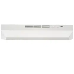
Painted hood surfaces
Wiping regularly with mild soap/detergent and warm water should protect painted hood surfaces.
Be cautious about us ing "New and Improved" cleaning agents.
Your hood is in stalled over hot cooking equipment.
Most chemicals found in cleaning agents react with heat to loosen paint.
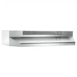
Stainless steeB hood surfaces
Stainless steel hoods should be washed regularly with a clean cloth. warm water and mild soap or dish detergent.
Clean in the direction of the polish lines. Rinse well with clear water and wipe dry immediately.
You may wish to apply light oil used for furniture polishing to emphasize it's bright finish.
Fan assembBy
Fan blade can be cleaned with a damp cloth and mild deter gent. Use care when cleaning fan blade - it must not become bent or misaligned.
DO NOTALLOW WATER TO ENTER MO TOR. Make sure all surfaces are completely dry before re installing filters and restoring power.
Motor is permanently lubricated.
Do not oil or disassemble motor.
Aluminum Grease F{mter
Parts Bag (4 hood mounting screws inside)
Light Bumb (75 W Maximum) (1 per hood) Purchase Iocally.
OPTmONAL PARTS (purchase separateJy)
CBean Cooking Filter (Non-ducted hoods only) (1 per hood) Sears Part No. 97007696
Non-Ducted Kit (For use with 3¼" x 10" Duct) dncludes 3¼" x 10" Damper & 'Vent Cover) Sears Part No. 59102
74rich Round Damper (For use with 7-inch Round Duct) Sears Part No. 59183
SpBashpmate Sears Part Nos.
58120 Black/Biscuit 58128 White/Almond 58129 Stainless 58130 Black/Biscuit 58138 White/Almond 58139 Stainless
Cord Kit (Allows hood to be plugged into a standard 120 VAC wall outlet) Sears Part No. 233.22HCK44D
Ducting Accessories (See "Equivalent Duct Length Chart" on page 5 for Ducting Accessory Model Nos.)
"Parts Not ncluded With Hood" available by calling Sears at I=800-4=MYHOME
(DriH
Tape Measure
Duct Tape
S wire
Kenmore rangehoodsaredesigned toperformefficiently thishood wiIIfunctionatapproximately 80%ofitsratedairftowwhen200equivalent feetof7"roundductwork isattached.Usethischart tocalculatetheequivalent duct length of your system.
Broan Modem 401 Straight Duct 3¼=in. x lO-in. × 2=ft. mong Equivalent length 2ft.
Broan Modem 406 Straight Duct 64n. round × 2-ft. long Equivalent length 2 ft.
Broan Modem 407 Straight Duct 7-in. round × 2-ft. long EquivaIent Iength 2 ft.
Broan Modem419 64n.
Round Elbow Equivalent length 8 ft.
Broan Modem415 7-in.
Round Elbow Equivalent length 8 ft.
Sears Model 59581
3¼-in. x lO-in. to 6=in. Round Transition Equivalent length 5.5 ft.
Broan Model 412H
3¼=in. x lO-in. to 7=inoRound Transition Equivalent Iength 5.5 ft.
Broan Model 3¼-in° x lO=in.
Right=angBe Embow Equivalent Iength 8.5 ft.
Broan _'1odel 429
3¼-in. x lO-ino Right-angle Fiat Elbow Equivalent length 24 ft.
Broan Model 430
3¼-in. x lO-ino Right-angme Short Eave E{bow quivalent length 15 ft.
Broan Model
3¼-in. x lO-in.
Right-angle Long Eave Elbow quivalent length 15 ft.
Sears Modem 59691
8=in° Round Wall Cap Equivalent length 34 ft.
(6-ft=w/o damper)
Broan Modem 647
74n.
Round Wall Cap Equivalent length 34 ft. (6-ft=w/o damper)
Sears Model 59391 3¼=in. x lO-in.
Wall Cap Equivalent length 45 ft.
(7-ft= w/o damper)
Model 59091 Roof Cap (accepts 74n. round or 3¼-in. × lO-in. duct} Equivalent Iength 30 ft. (7-fL W/Odamper)
Sears Modet "Ducting Accessories" avaimabmeby calling: Sears at 1-800-4-MY-HOME
Broan Modet "Ducting Accessories" availabme by calling: 1800=558=1711°
{b re
Determine whether hood will discharge vertically (3¼" x 10" or 7" Round). horizontally (3¼" x 10" only) or non ducted.
For vertica! or horizonta! discharge. run ductwork between the hood location and a roof cap or wall cap.
For best results. use a minimum number of transitions and elbows.
ROOF CAP
3¼" X 10" or
7" ROUND DUCT (For vertical discharge)
30" ABOVE COOKINGSURFACE 3¼" X 10" DUCT (For horizontal discharge)
Use these diagrams for proper placement of ductwork and electricaJ cutout in cabinet or wall.
For a non-ducted installation.
DO NOT cut a duct access hole.
X 10" HOOD MOUNTING SCREWS (4) VERTICAL DUCTING
Run house wiring between service panel and hood location. ELECTRICAL ACCESS HOLE WOOD SHIMS CENTER (recessed-bottom UNE (in cabinet bottom) cabinets only)
7" ROUND VERTICAL DUCTING HOOD MOUNTING SCREWS (4)
1 015/16" (24" hood) 1 015/16" (24" hood)
1315/16" (30" hood) (30" hood)
DUCT
(recessed-bottom CENTER cabinets onmy) LmNE
ELECTRICAL ACCESS HOLE (in cabinet bottom)
Remove from nose of hood.
SHiPPiNG TAPE
2. Remove WiringCover from inside the hood. Set cover and mounting screw aside.
See page 4 for Non-Ducted Kit information.
Non-Ducted Kit availabme by calming Sears at 1-800=4=MY-HOME
COVER
See page 4 for 7" Round Damper information.
7" Round Damper is available by calling Sears at 1-SOO=4=MY-HOME
3. Remove appropriate Duct Knockout from top or back of hood.
See page 4 for Ducted Kit information.
Ducted Kit is avaimabmeby calling Sears at 1-800=4-MY-HOME
TOP RECTANGULAR DUCT KNOCKOUT (Remove for 3¼" x 10" vertical discharge)
REAR RECTANGULAR DUCT KNOCKOUT (Remove for 3¼ "x 10" horizom'al discharge)
4. Attach x 10" Damper/Duct Connector over knockout opening.
Make sure damper Pivot is nearest to W/Back Edge of hood. Remove any shipping tape from damper flap.
V4"x 10" DAMPER/DUCT CONNECTOR PIVOT
5. Instal! Vent Cover over louvers at the front of hood. Insert Tabs into top louvers. rotate cover downward. and snap cover into bottom louvers.
VENT COVER/
TABS
6. Remove either top or back Wiring Knockout and instalI approved Electricam Cabme Cream#.
WIRING KNOCKOUT
ELECTRICAL CABLE CLAMP
WARNING: To reduce the risk of eJectric shock. make sure power is switched off at the service panel. Lock or tag service panet to prevent power from being switched on acci dentally.
1= Connect House Wiring (120 VAC) to hood. Use a piece of Cardboard to protect the cooktop. if necessary.
A Cord Kit is avaimable = which enables the hood to plug into a standard 120 VAC wall outmeto
See page 4 for Cord Kit information.
Cord Kit available by calling Sears at 1-80O=4=MY-HOME ®
HOUSE WIRING (120 VAC)
CARDBOARD (Use to protect cooktop)
2= Connect house black to hood black wire. house white to hood white wire. and house ground under Green Ground
Screw.
Securely tighten cable clamp onto house wiring.
3. Replace wiring cover.
Hang hood from4 Mount. from parts bag !i!ilii!i!_!'_!_! Slide hood towards watI until mounting screws are engaged in narrow end of (4) homes.
Tighten mounting screws securely.
CAUTION: Do not push on filter or fan blade!
Pushing on the filter or fan bmade may cause them to interfere with other hood parts.
KEYHOLE MOUNTING SCREW
DUCT TAPE 3¼" x 10" DUCTWORK
2. Connect ductwork to hood.
5094. 5104. & 5114 Models use 3¼" x 10" Ductwork.
5154. 5164. & 5174 Models use 7" Round Ductwork.
Use Duct to make joints secure and air tight.
3. install a 75 W Ma×imum Light Bulb.
Purchase bulb locally.
Gently squeeze Lqht Lens LeeiA to remove and replace lens.
CAUTION: Bulbs may be hot! Refer to bulb pack aging for further information.
4. Make sure fan bIade turns freely. Turn on power at service panel. and test for proper operation.
75 W MAXIMUM LIGHT BULB
LIGHT LENS LEGS
13 .14
KEY NO.
5094 5154 5104 5164 5114 5174 PART NO.
98006621 99170245
99270987 99110437 97011217
99020272 99260428
98005568 97012248
97006931 99420472 97010709
99090989 99030315
99030316
99030310 99030311 97005678
99150471
99043200
DESCRiPTiON
Outlet Box Cover 8-18 x 3/8 Phillips Truss Sheet Metal Screw* Bulb Holder with Wires Light Lens Screw/Nut Kit (includes 2 - #10-16 x .500 Screws and 2 - #10-16 Sheet Meta! Nuts) Fan Blade #6-32 Locking Nuts* (2 Required) Motor Mounting Bracket Motor Assembly (Includes Key Nos.
7.8&9) Aluminum Filter Filter Retainer Nameplate Black Nameplate White 2-Speed Motor Switch Black 2-Speed Motor Switch White Light Switch Black Light Switch - White Motor Receptacle with Wires #10-32 x 1/2 Green Ground Screw* Installation Instructions
+Standard Hardware.
May be purchased locally.
+*Not illustrated.
Your Home
® Registered Trademark / TMTrademark / sMSewice Mark of Sears. Roebuck and Co.
® Marca Registrada / TMMarca de F&brica / sMMarca de Sevicio de Sears.
Roebuck and Co.
MCMarque de commerce / MDMarque dposee de Sears. Roebuck and Co. ® Sears. Roebuck and Co.