Loading ...
Loading ...
Loading ...
SYSTEM CONFIGURATION
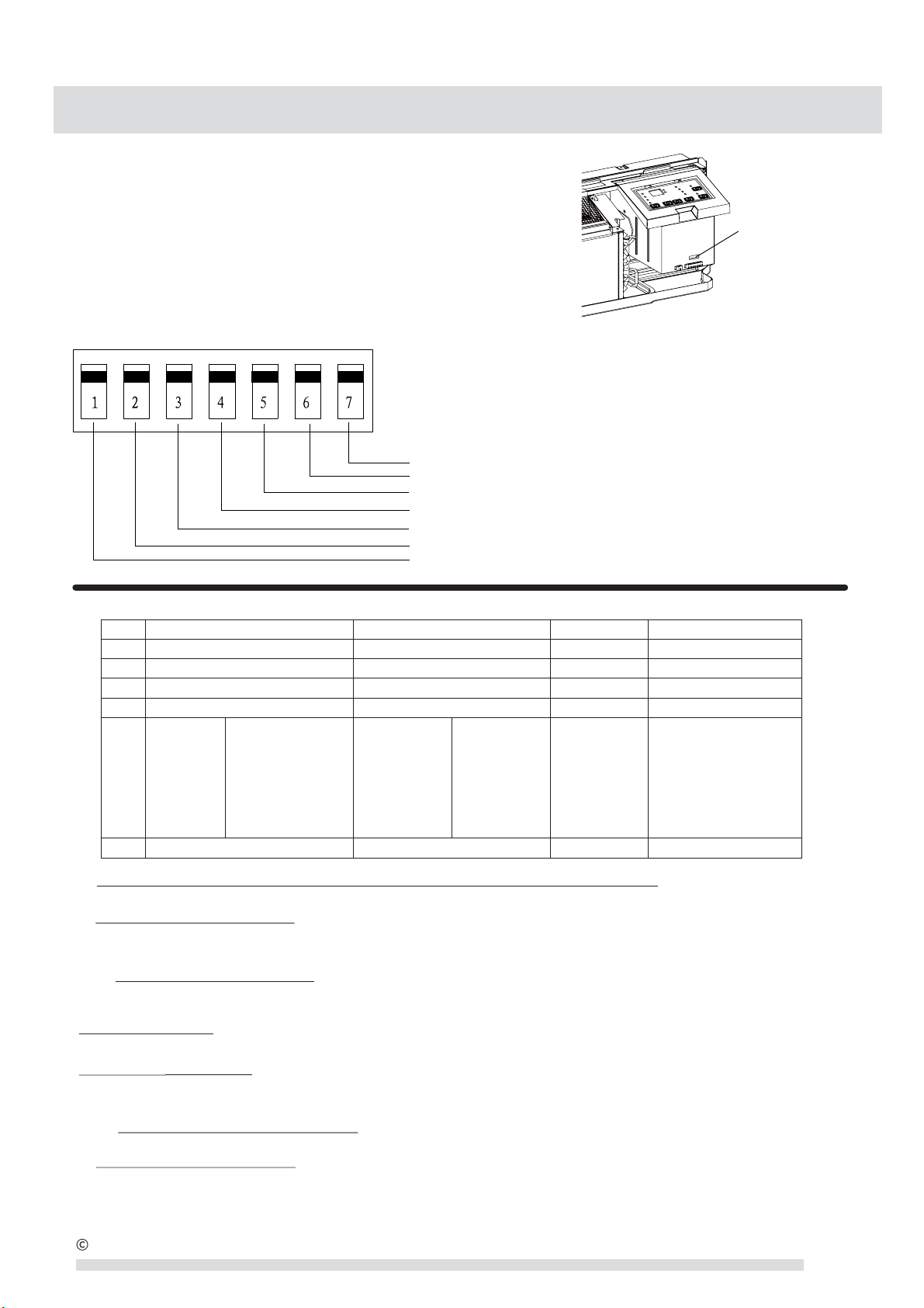
DIP SWITCHES
Auxiliary dip switch controls are located behind the front
panel, through an opening below the control panel.
To access, remove front panel. See Fig. 10.
Dip switches are accessible without opening the
control box. Unit must be powered OFF to effectively
change their status.
Factory settings for dip switches will be in the
DOWN position. See Table 4 - Dip Switch Functions
for functions of each dip switch position.
Fig.16 –Dipswitch Location on Unit
Dip Switches
Dipswitch
Up
Down
Freeze guard
Fig.17 –Dip Switches
Electric heat only (for Heat Pumps)
Setpoint Limit 2
Setpoint Limit 1
Fan CON/CYC for cooling/Energy Saver: Cooling
Fan CON/CYC for heating/Energy Saver: Heating
Wall Thermostat enable
Table 4—DIP SWITCH FUNCTIONS
1.Electric Heating Only / Emergency Heat (For Heat Pump Units Only)
This setting is typically used for Emergency Heating.
2.Wall Thermostat Enable
A wired wall thermostat can be connected to the unit. The dip switch must be adjusted accordingly in order to
allow the wall thermostat control of the unit. When in wall thermostat mode, the control panel will be disabled.
3*4.Energy Saver Dip Switches
Allows the fan to operate in continuous or cycle modes while the unit is in heating or cooling mode
(continuous or cycle):
CON (Continuous)
Allows fan to run continuously, circulating air even when the temperature setting has been satisfied.
CYC (Cycle)/Energy Saver
This setting allows the fan to cycle on and off with the compressor or electric heater. The fan stops a
short time after the temperature setting is satisfied.This is the most efficient mode for electrical usage.
5*6.Setpoint Temperature Limits
Provides a range of temperature control.
7.Room Freeze Protection
If the unit senses a room temperature below 40°F, the fan motor and electric strip heat will turn on and
warm the room to 50°F. The fan stops a short time after the temperature is satisfied.
No, UP DOWN DEFAULT REMARKS
1 Electric Heat Only Heat Pump DOWN For Heat Pump unit only
2 Wall Thermostat Enable Control Panel Enable DOWN
3 Fan Continuous Run for Heating Fan Cycle for Heat DOWN
4 Fan Cycle for Cool Fan Continuous Run for Cooling DOWN
5*6
UP*UP
68---75℉
20---24℃
UP*DOWN
63---80℉
18---28℃
DOWN*UP
65---78℉
19---26℃
DOWN*DOWN
61---86℉
16---30℃
(full range)
DOWN*DOWN
Two configurations (5*6)
Combine to select set
point range.
When set point limit set,
display always shows
full rang
e.
7 Freeze Guard Disable Freeze Guard Enable DOWN
61---86℉
16---30℃
2010 Electrolux Home Products, Inc. All rights reserved.
9
Loading ...
Loading ...
Loading ...