Loading ...
Loading ...
Loading ...
8
Complete Preparation
1. Determine and make all necessary cuts in the wall for the vent
system. Install the vent system before installing the range
hood. See the “Venting Requirements” section.
2. Determine the location where the power supply cable will be
run through the wall. Be sure that the location will be covered
by the chimney of the range hood.
3. Drill a 1¹⁄₄" (3.2 cm) hole at this location.
4. Pull enough power supply cable through the wall to allow for
easy connection to the terminal box.
NOTE: Your range hood requires you to purchase either an
internal type or an in-line (external type) blower motor system.
For internal blower systems, there are blower motor mounting
parts in the blower motor installation packet that must be added
to the range hood prior to mounting the range hood to the wall.
See the “Install Range Hood Internal Blower Motor” section and
the instructions supplied with the blower motor.
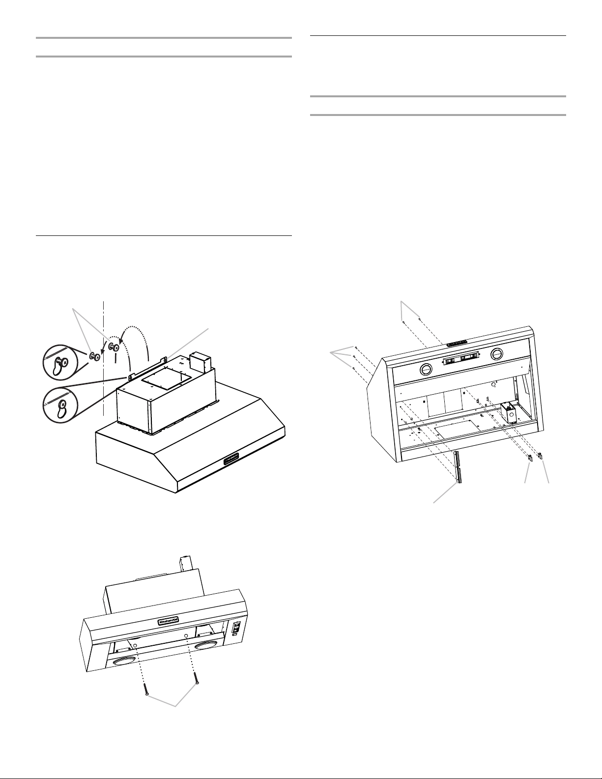
Install Range Hood
1. Remove the grease filter. See “Range Hood Care” section.
2. Using 2 or more people, hang range hood on 2 mounting
screws through the mounting slots on back of range hood.
3. Level the range hood and tighten upper mounting screws.
4. Install 2 - 5 x 45 mm lower mounting screws and tighten.
Install Range Hood Internal Blower Motor
NOTE: Your range hood requires you to purchase either an
internal type or an in-line (external type) blower motor system.
See “Blower Motor System” in the “Accessories” section.
Prepare the Internal Blower System
IMPORTANT: Perform steps 1-4 before mounting the range
hood.
1. Remove grease filters from range hood. See the “Range
Hood Care” section in the Use and Care Guide.
2. Install the motor support bracket using three 4.2 x 8 mm
screws. Screw bracket to the inside top or back (alternate
location on some models), toward the left side of the range
hood.
3. Install motor spring clip using two 4.2 x 8 mm screws. Screw
spring clip to the inside top or back (alternate location on
some models) of the range hood at the proper location for the
selected motor system. Slide the mounting tab of the spring
clip through the slot in the panel and secure with the screws.
Use the inside set of mounting holes for the single motor
system. Use the outside set of mounting holes for the dual
motor system.
A. Mounting screws
B. Mounting slots
A. Lower mounting screws
A
B
A
A. 4.2 x 8 mm screws (3) for motor support bracket
B. 4.2 x 8 mm screws (2) for motor spring clip
C. Motor support bracket
D. Motor spring clip (single motor assembly location)
E. Motor spring clip (dual motor assembly location)
C
A
D
E
B
Loading ...
Loading ...
Loading ...