This unit has many exciting features which are different from those found on standard PTAC models. The owner must be familiar with these features in order to fully understand the operation and capability of the unit.
Dry Mode -- For increased comfort and humidity management, an added "Dry Mode" is standard on all Frigidaire PTAC's. This mode feature will help manage and reduce the humidity content within the living space, making it more comfortable. In DRY mode, the unit will modulate cooling mode at low fan speed until the room temperature is 4° F below the room temperature setting regardless of fan mode selection. Dry mode should not be considered a substitute for a standalone dehumidifier. In "dry mode" more condensation will be created and the use of a "drain kit" (5304480570) is recommended.
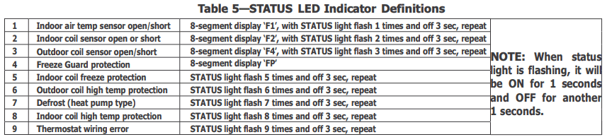
Intelligence - Your unit has an on board computer that utilizes real time diagnostics to prong the life of your unit. There is an LED indicator on the control board, behind the front panel, that will flash an error code if the unit has detected some kind of faulty condition. In many cases, the unit will automatically clear the fault condition and continue operating with no interruption. In some cases, the condition cannot be cleared and the unit will require service. In those cases, an "Fx" failure mode will be displayed on the digital display. For a detailed list of all error codes and “Fx” conditions, see table 5 - Status LED Indicator Definitions for further details.
Memory - Your unit also has memory. If power is lost, all of the control settings (setpoint, mode, fan speed, on/off and configuration) are remembered. So when power is restored, the unit will start back up in the mode (and configuration) it was in, when power was lost.
Quiet Design - Not only does the unit have 2 fan motors and a tangential blower for optimistic sound, the indoor fan will always run a minimum of 10 seconds before the compressor, to help reduce the sound of the compressor starting
Random Compressor Restart - To help prevent power surges after a power outage (many PTACs starting at the same time), the compressor is equipped with a 2 minutes 45 seconds to 3 minutes 15 seconds random restart delay feature. Whenever the unit is plugged in, or power has been restarted, a random compressor restart will occur to help avoid power surges.
Automatic Room Freeze Protection - This protection feature will automatic ensure the indoor temperature does not fall below freezing. When your PTAC is configured for freezer protection (which is the default condition), then whenever power is supplied to the unit, if the unit senses temperature below 40 °F, the fan motor and electric heater are turned on and will warm the room to 50°F. Freeze protection can be switched off, change the configuration switch to turn the feature off.
Automatic Quick Warm-Up (for heat pump models only) - If the room temperature falls to 5°F blow the set point temperature, the reverse cycle heat is shut off and the electric strip heat is turned on for one cycle, until room temperature rises.
Dual -8 Display and LED Display - Two 8-segment nixie tubes, 13 LED indicators (They are HIGH, MED, LOW, AUTO, COOL, FAN, HEAT, ON/OFF, SETPOINT, INDOOR, STATUS and TIMER)
Fan Configure for Optimization of Selected Application - The unit can be optimized to selected application by configuring the fan to run in continuous mode or cycle on and off with the compressor and electric heater (can be different for both heating and cooling modes). In cycle mode, the fan will continue to run after compressor or electric heater stops in order to blow off any residual heat or cool left on coil.
Fan Motors-Permanently Lubricated -- The unit have two fan motors for quiet operation and maximum operating efficiency. Motors are permanently lubricated to reduce maintenance and totally enclosed to keep dirt and water out of the motor windings.
Outdoor Fan -- The unit automatically selects the most efficient speed for the outdoor fan. The operating sound level is lower when the outdoor fan can operate in low speed yet there are situations where it must operate in high speed. The unit changes the fan speed automatically.
Indoor Fan Speed Selections-HIGH/LOW -- The unit automatically selects the most efficient speed for the outdoor fan. The operating sound level is lower when the outdoor fan can operate in low speed yet there are situations where it must operate in high speed. The unit changes the fan speed automatically.
OPERATION
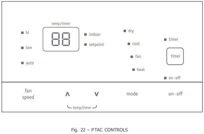
ABOUT THE CONTROLS ON YOUR UNIT
"ON-OFF" : It is used for turning the unit ON / OFF.
"mode": it is used for switching between Dry, Cool, Fan and Heat mode.
"∧" is used for increasing temperature or timer setting.
"V" is used for decreasing temperature or timer setting.
“fan speed”: It is used for setting high, low or auto fan speed. The corresponding LED will be lit when selected.
“timer”: It is used for setting the timer function.
Timer function
Timer ON: When the unit is off, timer ON can be set. Setting range is 0.5~24h. When timer ON time is reached, the system will operate according to the set mode.
Timer OFF: When the unit is off, timer OFF can be set. Setting range is 0.5~24h. When timer OFF time is reached, the system will stop operation.
Timer setting: Press "timer" to set timer function and "timer" icon will be on. The time can be adjusted by pressing "A" or "V" buttons.
The range of timer setting is from 0.5h to 24h.
5seconds after timer setting, the timer function will be activated and "timer" icon will be on.
Timer preview: When timer function has been set, press "timer" to preview the remaining time of timer.
If timer function has been set, turning the unit or power on/off failure will cancel timer setting.
CARE AND CLEANING
FRONT PANEL AND CASE
Turn unit off and disconnect power supply.
To clean, use water and a mild detergent. DO NOT use bleach or abrasives. Some commercial cleaners may damage the plastic parts.
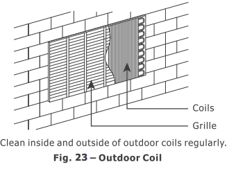
OUTDOOR COIL
Coil on outdoor side of unit should be checked annually. Unit will need to be removed from its sleeve to inspect dirt build-up that can occur inside of the coil. If clogged with dirt or soot, coil should be professionally cleaned. Under extreme conditions, more frequent cleanings may be required.
Clean the coils and basepan with a soft brush and compressed air or vacuum. A pressure washer may also be used, but be aware that the aluminium fins must not be bent. Use a gental up and down motion in the direction of the vertical aluminium fins when pressure washing coils.
CAUTION: UNIT DAMAGE HAZARD
Product failure due to improper care or lack of maintenance is not covered by warranty.
Airflow restriction may cause damage to the unit.
BASE PAN
Check base pan periodically and clean, if necessary.
AIR FILTERS
IMPORTANT: TURN UNIT OFF BEFORE CLEANING
CAUTION:UNIT DAMAGE HAZARD
Product failure due to improper care or lack of maintenance is not covered by warranty.
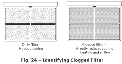
Do not operate unit without filters in place. If a filter becomes torn or damaged, it should be replaced immediately. Operating without filters in place or with damaged filters will allow dirt and dust to reach indoor coil and reduce cooling, heating, airflow and efficiency of unit. Airflow restriction may cause damage to unit.
To maintain unit efficiency clean the filters at least every 30 days (or sooner depending on application). Clogged filters reduce cooling, heating and airflow.
Keeping filters clean will:
Decrease cost of operation.
Save energy.
Prevent clogged indoor coil.
Reduce risk of premature component failure.
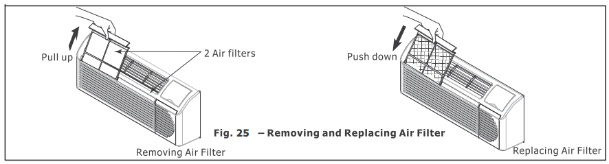
To Clean Air Filters:
Vacuum off heavy soil.
Run water through filters.
Dry thoroughly before replacing.
PREVENTATIVE MAINTENANCE
Preventative maintenance is essential to proper unit operation, efficiency and longevity.
To ensure equipment operates properly, it must be properly maintained. Equipment operation should be checked and verified several times during each year. During regular unit inspection and maintenance, follow the guidelines below:
Clean basepan and outdoor vent filter.
Clean outdoor orifice and fan.
Clean indoor coil. (Never use high pressure spray on indoor coils.)
Clean indoor fan, wire screen and front panel. (Best to use compressed air.)
Clean or install new indoor - air inlet filter(s).
Clean wall sleeve and outdoor grille.
Inspect cord and receptacle.
Secure electrical connections.
Ensure front panel is properly mounted and not damaged.
Ensure wall sleeve is installed properly.
Ensure heat and cool cycles operate properly.
TROUBLESHOOTING
POSSIBLE CAUSES
SOLUTIONS
UNIT DOES NOT START
Unit may have become unplugged
Circuit breaker may have been tripped
Unit may be off or in wall thermostat mode. Check section on dipswitch settings to verify dipswitches are set properly.
Unit may be in a protection or diagnostic failure mode. See section on Intelligent Self-checking Control.
Check that plug is plugged securely in wall receptacle. Note: LCDI plug has a test/reset button on it. Make sure that the LCDI plug has not tripped.
Replace the fuse. See Note 1.
Reset circuit breaker. See Note 1.
Turn unit on (bottom right button on keypad). Note: If the unit turns on, the LED will be green. If the unit is off, the LED will be red. If there is no LED on, there is a problem with power or damage to the control.
UNIT NOT COOLING/HEATING ROOM
Unit air discharge section is blocked
Temperature setting is not high or low enough. Note: Set point limits may not allow the unit to heat or cool the room to the desired temperature.
Check section on dipswitch settings.
Unit air filters are dirty.
Room is excessively hot or cold when unit is started.
Vent door left open.
Unit may be in a protection or diagnostic failure mode. Check section on Intelligent Self-checking Control.
Compressor is not running.
Make sure that curtains, blinds or furniture are not restricting or blocking unit airflow.
Reset to a lower or higher temperature setting.
Remove and clean filters.
Allow sufficient amount of time for unit to heat or cool the room. Start heating or cooling early before outdoor temperature, cooking heat or gatherings of people make room uncomfortable.
Close vent door.
Check dipswitch settings for desired comfort.
There is a protective time delay (approx.3 minutes) on starting the compressor after a power outage (or restarting after it has been turned off), to prevent tripping of the compressor overload.
DISPLAY HAS STRANGE NUMBERS/CHARACTERS ON IT
The unit may be in a diagnostic condition. Check Intelligent Self-Checking Control section to determine if unit has had a failure.
The unit may be set for °C(instead of °F), see the keypad configuration section
WATER DRIPPING OUTSIDE
If a drain kit has not been installed, condensation runoff during very hot and humid weather is normal. See Note 2. If a drain kit has been installed and is connected to a drain system, check gaskets and fittings around drain for leaks and plugs.
WATER DRIPPING INSIDE
Wall sleeve is not installed level
Wall sleeve must be installed level for proper drainage of condensation. Check that installation is level and make any necessary adjustments.
ICE OR FROST FORMS ON INDOOR COIL
Low outdoor temperature
Dirty filters
When outdoor temperature is approximately 55°F or below, frost may form on the indoor coil when unit is in Cooling mode. Switch unit to FAN operation until ice or frost melts.
Remove and clean filters.
COMPRESSOR PROTECTION
Power may have cycled, so compressor is in a restart protection
Random Compressor restart-Whenever the unit is plugged in, or power has been restarted, a random compressor restart will occur. After a power outage, the compressor will restart after approximately 3 minutes.
Compressor Protection-To prevent short cycling of the compressor, there is a random startup delay of 3 minutes and a minimum compressor run time of 3 minutes.