Loading ...
Loading ...
Loading ...
49-80622-5
11
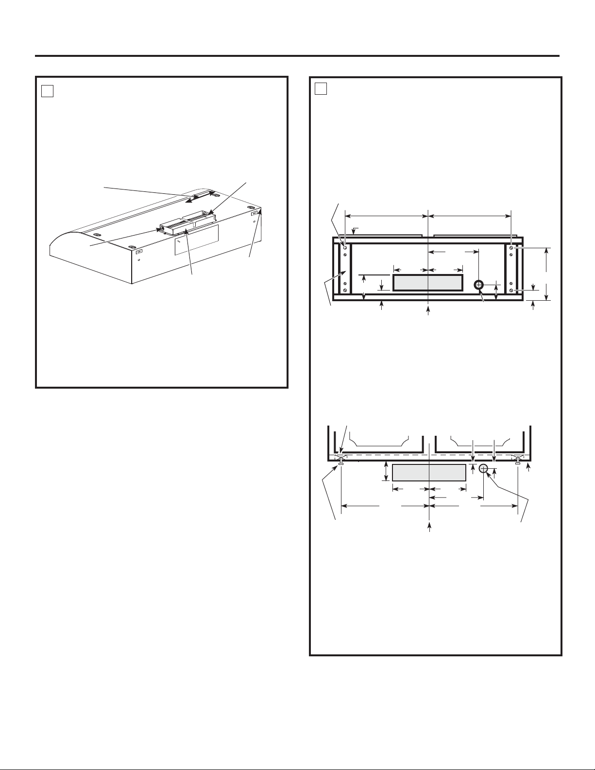
MARK HOLES
Select the vent option that your installation will require
DQGSURFHHGWRWKDWVHFWLRQ
Hood mounting screws (4)
13¾”
13¾
”
Cabinet front
Center
line
Electrical access
hole (in cabinet
bottom)
Wood shims
(recessed-bottom
cabinets only)
Vertical duct
access hole
9¼”
14
ø16”
1¼”
7
¾
”
3
11
/16”
11/16”
A.
Outside top exhaust
(Vertical duct–3
1
ø4
”
x 10
”
Rectangular)
• Use the diagram or the hood as a template and mark
the locations on the cabinet for ductwork, electrical
wiring and keyhole screw slots.
Cabinet Bottom
7
Wood shims (recessed-bottom cabinets only)
Cabinet front
Center line
Electrical
access hole
(in wall)
Hood mounting
screws (4)
Horizontal duct
access hole
Cabinet
bottom
13¾”
1¼”
½”
3½”
5
1
ø4”
5
1
ø4”
7¾”
13¾”
B.
Outside rear exhaust
(Horizontal duct–3
1
ø4
”
x 10
”
Rectangular)
• Use the diagram or the hood as a template and mark
the locations on the cabinet for ductwork, electrical
wiring and keyhole screw slots.
C.
Recirculating (non-vented ductless)
• Use the hood as a template and mark the locations
on the cabinet for the electrical wiring and keyhole
screw slots.
• Since the hood is to be recirculated (not to be vented
outside), do not cut out any vent openings in the wall
or cabinet bottom.
FOR 3
1
ø4” x 10” RECTANGLE DUCTED
DISCHARGE INSTALLATIONS:
Attach exhaust adaptor/damper over knockout
opening with two exhaust adaptor screws. Make sure
damper pivot is nearest to top/back edge of hood.
Remove tape from damper flap.
Up to 1” side-to-
side adjustment
Tape
Top/back edge
Exhaust adaptor/damper
(vertical discharge position
shown)
Pivot
6
Installation Instructions
NOTE: The exhaust adaptor/damper can be installed
up to 1 inch on either side of the hood center to
accommodate off-center ductwork. In extreme off-center
installations, one end of the duct connector may need to
be trimmed to clear the electrical cable clamp.
5
1
ø4”5
1
ø4”
Loading ...
Loading ...
Loading ...