Instructions for use Rangehood
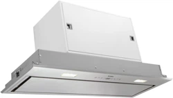
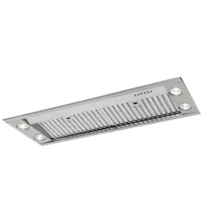
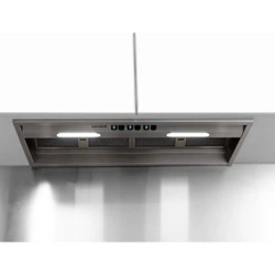
YOUR BUILT-IN UNIT
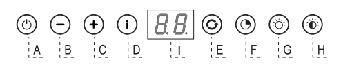
Description
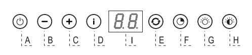
A Switch fan on/off
B Reduce extractor capacity
C Increase extractor capacity
D Engage intensive mode
E Clean air function/filter indication
F Timer function
G Switch lighting on/off
H Dim lighting
I Display
Introduction
 This user manual gives you a quick overview of all the possibilities offered by the appliance. You will find information on safety measures and maintaining the appliance.
Please retain this user manual and the installation guide. They may be of use to future users of the appliance.
Declaration of conformity
We declare that our products meet the applicable European Directives, Decisions and Regulations and the requirements listed in the standards referenced.
 Read the separate safety instructions before using the device!
USE
Controls
Switching the fan on and off
- Switch the fan on with the on/off button (A) and select the desired extractor setting with buttons ‘B’ and ‘C’. The ‘I’ display indicates which setting has been selected.
- Use button ‘D’ to switch on the intensive setting. “HI” appears in the ‘I’ display.
After 6 minutes the intensive mode is automatically reduced to the setting previously selected.
Switching the lighting on and off
- Use the ‘G’ button to switch the lighting on and off.
Dimming the lighting
- Dim the lighting with button ‘H’. The strength of the lighting varies between maximum and minimum, and vice-versa.
Clean Air function:
With the Clean Air function you can refresh the air in the kitchen over maximum 24 hours.
- Make sure the built-in unit has been switched off.
- Press on the Clean Air button ‘E’.
Every hour, the extractor hood will switch on for 10 minutes automatically, at the lowest extraction setting. The display reads "24" and an indicator flashes at the bottom right.
Switching on the timer
- Switch on the extractor hood with button ‘A’.
- Set the extraction strength with buttons ‘B’ and ‘C’.
- Press the Timer button ‘F’.
The extractor hood switches off automatically after 30 minutes. Switch off the Timer function by pressing button ‘F’ again, or by switching off the extractor hood with button ‘A’. The display shows the selected speed and the remaining time.
Grease filter indicator
After 100 hours of use the “FF” indicator is shown in the display.
- Clean the grease filters.
- Reset the filter indicator. While the hood is switched off, press button ‘E’ for 3 seconds until the filter indicator disappears.
Carbon filter indicator
After 200 hours of use the “EF” indicator is shown in the display.
- Replace the carbon filters.
- Reset the filter indicator. While the hood is switched off, press button ‘E’ for 3 seconds until the filter indicator disappears.
MAINTENANCE
Cleaning
Attention! Before performing any maintenance operation, isolate the hood from the electrical supply by switching off at the connector and removing the connector fuse. Or if the appliance has been connected through a plug and socket, then the plug must be removed from the socket.
The built in unit should be cleaned regularly (at least with the same frequency with which you carry out maintenance of the fat filters) internally and externally. Do not use abrasive products. Do not use alcohol!
Attention! Failure to carry out the basic cleaning recommendations of the built in unit and replacement of the filters may cause fire risks. Therefore, we recommend oserving these instructions. The manufacturer declines all responsibility for any damage to the motor or any fire damage linked to inappropriate maintenance or failure to observe the above safety recommendations.
Built in unit
Clean the built in unit with soapy water and a soft cloth. Then wipe with clean water to rinse. Do not use aggressive cleaning agents such as soda. The built in unit paintwork will stay looking nice if you wax it occasionally.
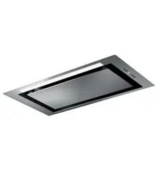
Stainless steel canopy hoods
Do not use any sort of scourer. Treat with a stainless steel care product and polish with the structure of the stainless steel.
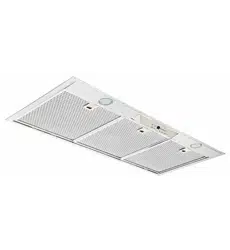
Metal grease filters
These must be cleaned once a month (or when the filter saturation indication system – if envisaged on the model in possession – indicates this necessity) using non aggressive detergents, either by hand or in the dishwasher, which must be set to a low temperature and a short cycle. The openings must be placed downwards to let the water run out of the filters. The cleaning agents will make the aluminium filter turn dull, this is normal.
Grease filters
Removing the grease filters
Switch off the electricity! Remove the plug from the socket or switch the electricity off at the mains. Open the panel and pull the special handle to remove the filter.
Replacing the carbon filter
The carbon filter must always be used if the built in unit is not ducted.
- Open the panel.
- Remove the grease filters.
- Fit the carbon filter by wedging it into the casing (D).
- Replace the filter grids in the extractor hood.
Note:
- Saturation of the activated charcoal will eventually occur after more or less prolonged use, depending on the type of cooking and how frequently the grease filter is cleaned.
- In all cases it is necessary to replace the cartridge at least every four months.
- DO NOT wash or reuse the carbon filter. Saturated carbon is not environmentally friendly, change the filter regularly.
Lighting
Changing the light bulbs
Faulty LEDs must be replaced by a professional installer.
INSTALLATION
General
This appliance should be connected to the power supply by a recognized fitter who is familiar with, and works according to the correct safety regulations. This appliance meets the European requirements.
Important that you know:
- The minimum distance between the supporting surface for the cooking vessels on the gashob and the lowest part of the range hood must be not less than 65 cm. For use with an electric, ceramic or induction hob, this distance must be at least 55 cm.
- If the built in unit is to be fitted to an existing duct no other appliances, such as a geyser or heater, may be connected to that same duct.
- Consider local regulations with respect to the ventilation of gas appliances.
- The shorter the duct, and the fewer the bends in it, the better the built in unit will work.
- Before you start drilling check that there are no installation cables present.
- The connecting pipe for the built in unit has a diameter of 120 or 150 mm. It is best also to use a flue pipe of the same diameter.
- The installation material supplied with this range hood is designed for fixing to reinforced concrete or masonry walls. For some types of walls you may need special plugs and screws.
Electrical connection
This appliance is manufactured in class I, it must therefore be connected to the earth system.
Make sure the supply voltage ratings correspond with those stated on the appliance data plate. The connection to the mains is carried out as follows:
BROWN = phase L
BLUE = phase N
YELLOW/GREEN = Earth
During the electrical connection make sure that the electrical socket is equipped with earth connection.
This canopy hood has been provided with a power plug. When installing the hood, make sure that this plug remains accessible.
Attention:
If you want to make a fixed connection, ensure that a multi-pole switch with a distance between contacts of 3 mm is installed in the supply cable.
Installation
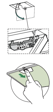
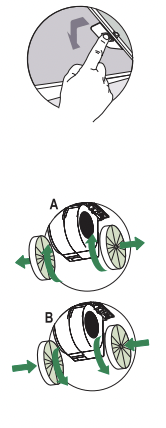
- Open the panel.
- Remove the grease filter.
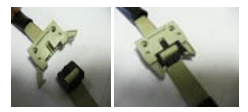
- Connect the controls together as depicted.
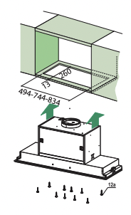
- First remove the 6 screws (2 on the left, 2 on the right, 2 on the front), followed by the frame.
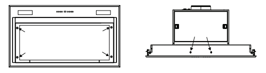
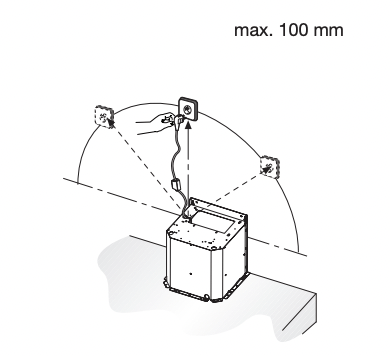
- Use a saw to create a recess in the bottom side of the cupboard (at a distance of at least 650 mm from a gas hob). Refer to the measurement drawing for this.
- Attach the unit with the 10 screws provided (12a).
- Put the frame into position.
- Restore the plug connection of the controls.
- Put the grease filter into position and close the panel.