Loading ...
MOUNTING THE BUILT-IN TOP UNIT:
Locate the installation kit containing mounting hardware packaged with the unit.
Place the unit in the cabinet opening so the knobs are toward the front of the unit.
Attach the mounting brackets to the underside of the unit with the screws provided.
Tighten the main bolt up to the underside of the counter top.
POWER CONNECTIONS TO APPLIANCES
We suggest that you have the dealer where you purchased your new cooktop install it
or have him arrange installation by a qualified electrician. Installation must conform
with local codes. In addition, installation must conform with the National Electric
Code NFPA70 latest edition.
WARNING – Be sure electric power is OFF at the fuse (breaker) box until the unit is
installed and ready to operate. See appliance rating label on the underside
of the unit for maximum K.W. and amperage rating.
WARNING
ELECTRICAL GROUNDING INSTRUCTIONS
Appliances with a 120 volt power cord are
equipped with a three prong grounding plug for
your protection against shock hazard and
should be plugged directly into a properly
grounded receptacle. Do not cut or remove the
grounding prong from this plug.
Do not use an extension cord to connect this appliance. If the power supply cord is
too short, have a qualified electrician or serviceman install an outlet near the
appliance.
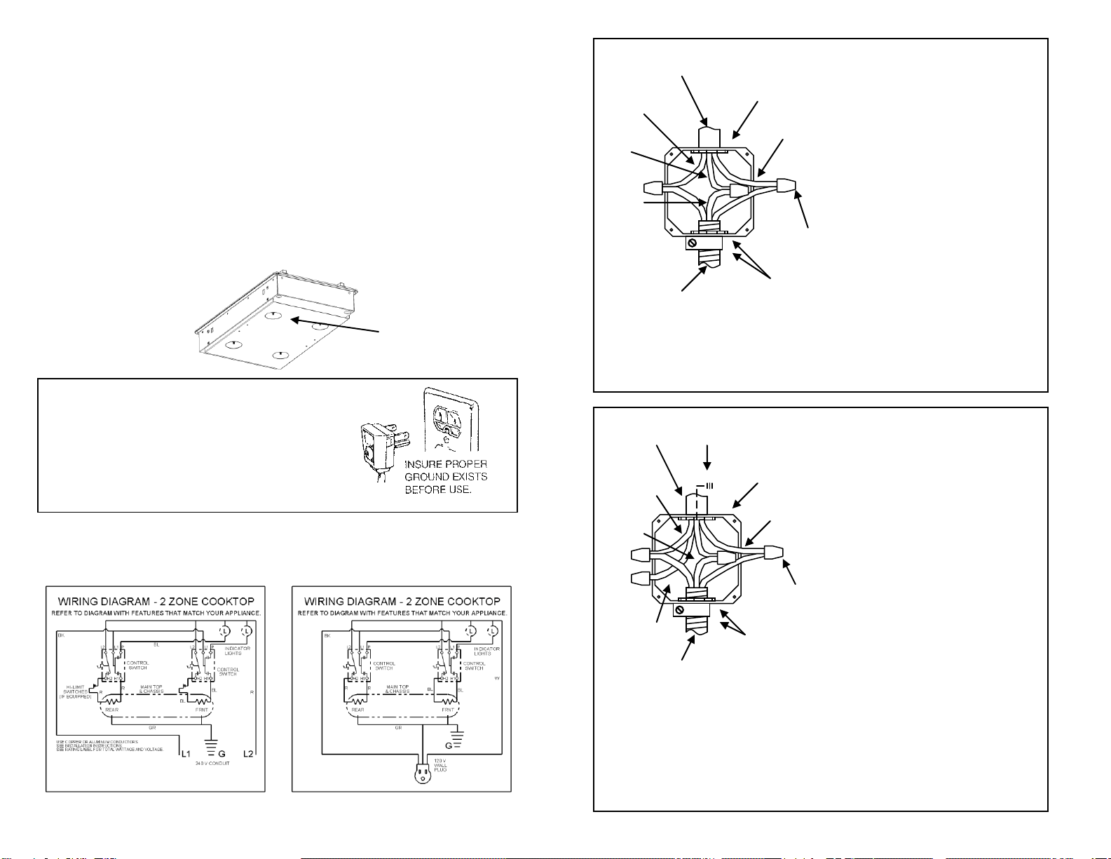
FOUR-WIRE CONDUIT CONNECTION
1. Remove the access plate to gain access
to the electrical junction box.
2. Install the three-wire range conduit and
an appropriate strain relief clamp
through the hole in the junction box.
3. Use an appropriate insulated wire
connector to connect the red and black
wires from the range conduit to the
corresponding red and black leads from
the branch circuit.
4. Connect the green (ground) wire from
the range conduit to the grounding lead
from the branch circuit in like manner.
5. The white (neutral) lead from the branch
circuit must be properly insulated away
from other all other leads.
5. Secure the strain relief clamp around the
conduit and tighten the nut against the
wall of the junction box.
6. Tuck all wire leads into the junction box
and replace the access plate removed
earlier in step 1.
Effective January 1, 1996 the National
Electrical Code requires that new
construction (not existing) utilize a 4-
conductor connection to an electric range.
NOTE: A 4-conductor connection is to be
used when the appliance is installed in a
mobile home or when local codes do not
permit grounding through the neutral.
240 VAC
JUNCTION BOX
(ACCESS PLATE
REMOVED)
BRANCH
CIRCUIT
BLACK
LEAD
INSULATED
WHITE LEAD
GREEN
(GROUND
TO UNIT)
RANGE
CONDUIT
INSULATED WIRE
CONNECTORS
STRAIN
RELIEF
CLAMP
& NUT
RED
LEAD
BRANCH
GROUND
LEAD
THREE-WIRE CONDUIT CONNECTION
1. Remove the access plate to gain access
to the electrical junction box.
2. Install the three-wire range conduit and
an appropriate strain relief clamp
through the hole in the junction box.
3. Use an appropriate insulated wire
connector to connect the red and black
wires from the range conduit to the
corresponding red and black leads from
the branch circuit.
4. Connect the green (ground) wire from
the range conduit to the white (neutral)
lead from the branch circuit in like
manner.
5. Secure the strain relief clamp around the
conduit and tighten the nut against the
wall of the junction box.
6. Tuck all wire leads into the junction box
and replace the access plate removed
earlier in step 1.
If local codes do not allow grounding
through the neutral, refer to the
illustration below of FOUR-WIRE
CONDUIT CONNECTION.
JUNCTION BOX
(ACCESS PLATE
REMOVED)
BRANCH
CIRCUIT
STRAIN
RELIEF
CLAMP
& NUT
BLACK
LEAD
RED
LEAD
WHITE
LEAD
RANGE
CONDUIT
INSULATED WIRE
CONNECTORS
GREEN
(GROUND
TO UNIT)
240 VAC
Rating Label
Location