United States
INSTALLATION AND SERVICEMUST BEPERFORMED BY A QUALIFIED INSTALLER.
IMPORTANT: SAVE FOR LOCAL ELECTRICAL INSPECTOR'S USE.
READ AND SAVE THESE INSTRUCTIONS FOR FUTURE REFERENCE.
FOR YOUR SAFETY: Do not store or use gasoline or other
flammable vapors and liquids in the vicinity of this or any other appliance.
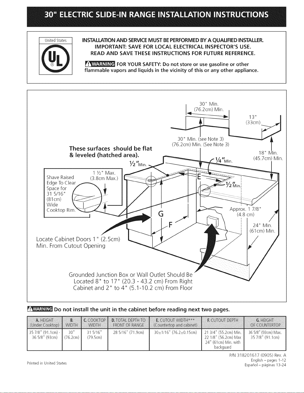
These surfaces should be flat
& leveled (hatched area).
Y2"Mio.
30" Min.
(76.2cm) Min. ,
(76.2cm) Min. See Note 3) /
18" Min.
Min. (45.7cm) Min.
Shave Raised
Edge ToClear
Spacefor
31 5/16"
(81cm)
Wide
Cooktop
1 1/2"Max.
(3.8cm Max.)
Locate Cabinet Doors 1" (2.5cm)
Min. From Cutout Opening
Approx. 1 7/8"
G (4.8 cm)
F
Grounded Junction Box or Wall Outlet Should Be
Located 8" to 17" (20.3 - 43.2 cm) From Right
Cabinet and 2" to 4" (5.1-10.2 cm) From Floor
24" Min.
(61cm) Min.
Do not install the unit in the cabinet before reading next two pages.
35 7/8" (91.1cm) - 31 5/16" 28 5/16" (71.9cm) 30_+1/16" (76.2_+0.15cm) 21 3/4" (55.2cm) Min.
36 5/8" (93cm) (79.5cm) 22 1/8" (56.2cm) Max
24" (61cm) Min. with
backguard
Printed in United States
36 5/8" (93cm) Max.
35 7/8" (91.1cm)
P/N 318201617 (0905) Rev. A
English - pages 1-12
Espahol - p_iginas 13-24
NOTES:
1. Do not pinch the power supply cord between the range and the wall.
2. Do not seal the range to the side cabinets. 213/_"
3.24" (61cm) minimum clearance between
the cooktop and the bottom of the
cabinet when the bottom of wood or
metal cabinet is protected by not less
than !/4" (0.64cm)flame retardant
millboard covered with not less than No.
28 MSG sheet metal, 0.015" (0.4mm)
stainless steel, 0.024" (0.6mm)
aluminum, or 0.020" (0.5 mm)
copper.
30" (76.2cm) minimum
clearance when the cabinet is
unprotected.
4. For cutouts below 22 7/8"
(58.1cm), appliance will slightly
show out of the cabinet.
5. Allow at least 19 ¼" (48.9cm)
clearance for door depth when
it is open.
Door Open
(see note 5)
/
1
/
ide Panel
A
IMPORTANT: Cabinet and countertop
width should match the cutout width.
E
FRONT
OF
CABINET
22 7/8" (58.1 cm) min.
23 1/4" (59.05cm)max.
(see Note 4) _ ["
1 1/8"
(2.86cm)
Ref.
35 7/8" (91.1cm) -
36 5/8" (93cm)
31 5/16"
(79.5cm)
28 5/16" (71.9cm) 30_+1/16" (76.2_+0.15cm) 21 3/4" (55.2cm) Min.
22 1/8" (56.2cm) Max
24" (61cm) Min. with
backguard
36 5/8" (93cm) Max.
35 7/8" (91.1cm) Min.
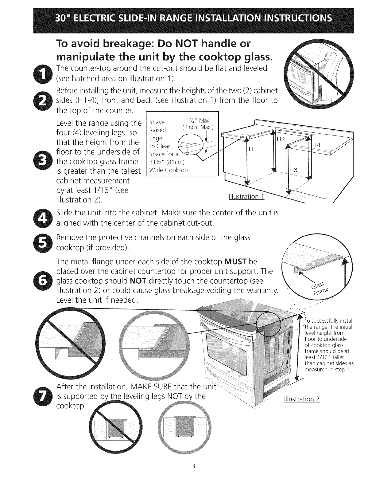
To avoid breakage: Do NOT handle or
manipulate the unit by the cooktop glass.
The counter-top around the cut-out should be flat and leveled
(see hatched area on illustration 1).
Before installing the unit, measure the heights of the two (2) cabinet
sides (H1-4), front and back (see illustration 1) from the floor to
the top of the counter.
Level the range using the
four (4)leveling legs so
that the height from the
floor to the underside of
the cooktop glass frame
is greater than the tallest
cabinet measurement
by at least 1/16" (see
illustration 2).
Shave
Raised
Edge
to Clear
Spacefor
311/2" (81cm)
Wide Cooktop.
1 1/2"Max.
(3.8cmMax.)
Illustration 1
Slide the unit into the cabinet. Make sure the center of the unit is
aligned with the center of the cabinet cut-out.
Remove the protective channels on each side of the glass
cooktop (if provided).
The metal flange under each side of the cooktop MUST be
placed over the cabinet countertop for proper unit support. The
glass cooktop should NOT directly touch the countertop (see
illustration 2) or could cause glass breakage voiding the warranty.
Level the unit if needed.
.-Tosuccessfully install
range, the initial
level height from
floor to underside
of cooktop glass
frame should be at
least 1/16" taller
than cabinet sides as
measured in step 1.
After the installation, MAKE SUREthat the uni
is supported by the leveling legs NOT by the
cooktop.
Illustration 2
3
Important Notes to the Installer
1. Read all instructions contained in these installation
instructions before installing range.
2. Removeall packing material from the oven compartments
before connecting the electrical supply to the range.
3. Observe all governing codes and ordinances.
4. Be sure to leave these instructions with the consumer.
Important Note to the Consumer
Keep these instructions with your owner's guide for future
reference.
IMPORTANT SAFETY
INSTRUCTIONS
• Be sure your range is installed and grounded
properly by a qualified installer or service
technician.
• This range must be electrically grounded in
accordance with local codes or, in their absence,
with the National Electrical Code ANSI/NFPA No.
70--latest edition in United States
• The installation of appliances designed for
manufactured (mobile) home installation must conform
with Manufactured Home Construction and Safety
Standard, title 24CFR, part 3280 [Formerly the Federal
Standard for Mobile Home Construction and Safety,
title 24, HUD (part 280)] or when such standard
is not applicable, the Standard for Manufactured
Home Installation 1982 (Manufactured Home Sites,
Communities and Setups), ANSI Z225.1/NFPA 501A-
latest edition, or with local codes in United States.
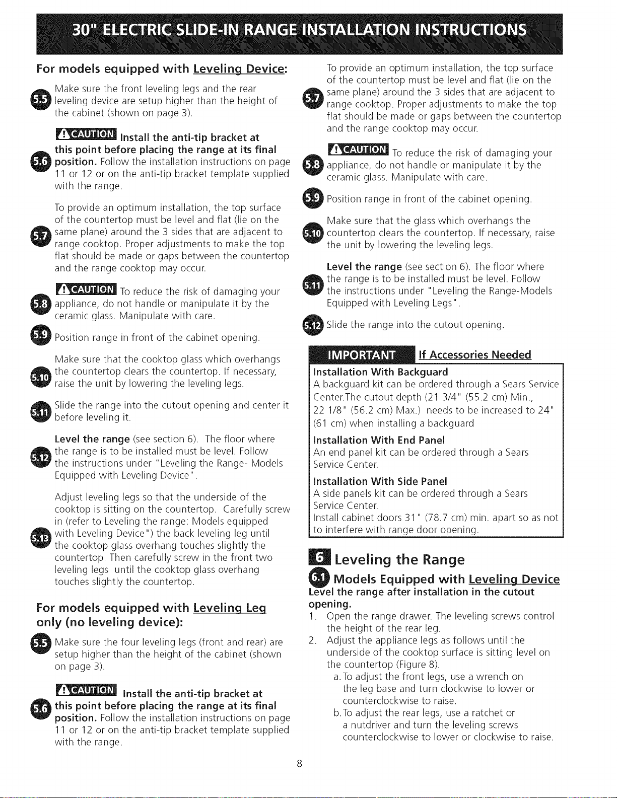
Stepping, leaning or sitting on the
door or drawer of this range can result in serious
injuries and can also cause damage to the range.
• Do not store items of interest to children in
the cabinets above the range. Children could be
seriously burned climbing on the range to reach items.
• To eliminate the need to reach over the surface
units, cabinet storage space above the units
should be avoided.
• Do not use the oven as a storage space. This
creates a _otentially hazardous situation.
• Never use your range for warming or heating the
room. Prolonged use of the range without adequate
ventilation can be dangerous.
• Do not store or use gasoline or other flammable
vapors and liquids near this or any other
appliance. Explosions or fires could result.
• Reset all controls to the "off" position after using
a programmable timing operation,
FOR MODELS WITH SELF-CLEAN FEATURE:
• Remove broiler pan, food and other utensils
before self-cleaning the oven, Wipe up excess
spillage. Follow the precleaning instructions in the
Owner's Guide.
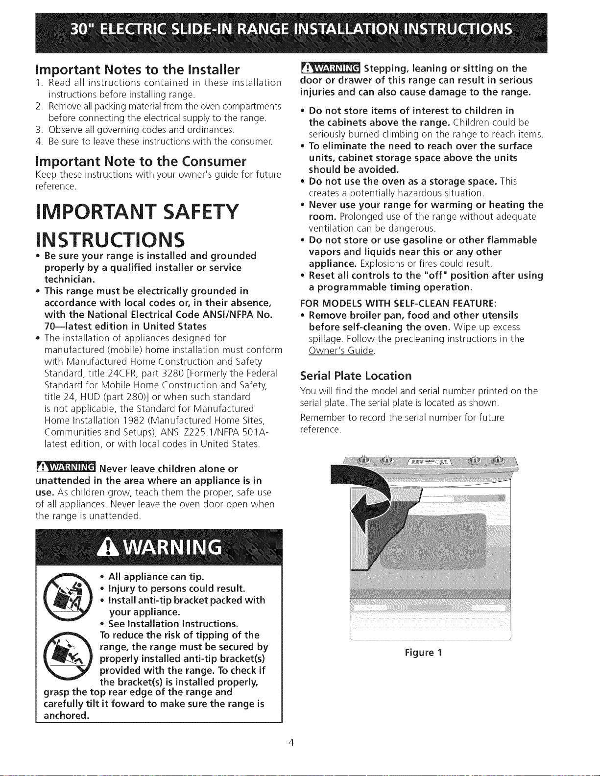
Serial Plate Location
You will find the model and serial number printed on the
serial plate. The serial plate is located asshown.
Remember to record the serial number for future
reference.
Never leave children alone or
unattended in the area where an appliance is in
use. As children grow, teach them the proper, safe use
of all appliances. Never leave the oven door open when
the range is unattended.
• AlL appliance can tip.
• Injury to persons could result.
• Install anti-tip bracket packed with
your appliance.
• See Installation Instructions,
To reduce the risk of tipping of the
range, the range must be secured by
properly installed anti-tip bracket(s)
provided with the range, To check if
the bracket(s) is installed properly,
grasp the top rear edge of the range and
carefully tilt it foward to make sure the range is
anchored,
Figure I
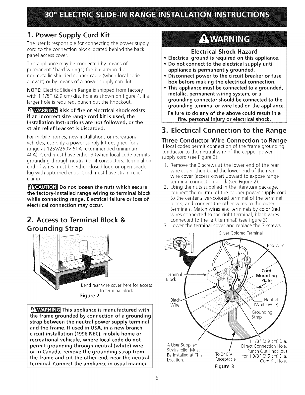
1. Power Supply Cord Kit
The user is responsible for connecting the power supply
cord to the connection block located behind the back
panel access cover.
This appliance may be connected by means of
permanent "hard wiring"; flexible armored or
nonmetallic shielded copper cable (when local code
allow it) or by means of a power supply cord kit.
NOTE: Electric Slide-in Range is shipped from factory
with 1 1/8" (2.9 cm) dia. hole as shown on figure 4. If a
larger hole is required, punch out the knockout.
Risk of fire or electrical shock exists
if an incorrect size range cord kit is used, the
Installation Instructions are not followed, or the
strain relief bracket is discarded,
For mobile homes, new installations or recreational
vehicles, use only a power supply kit designed for a
range at 125V/250V 50A recommended (minimum
40A). Cord must have either 3 (when local code permits
grounding through neutral) or 4 conductors. Terminal on
end of wires must be either closed loop or open spade
lug with upturned ends. Cord must have strain-relief
clamp.
Do not loosen the nuts which secure
the factory-installed range wiring to terminal block
while connecting range. Electrical failure or loss of
electrical connection may occur,
2. Access to Terminal Block &
Grounding Strap
Electrical Shock Hazard
o Electrical ground is required on this appliance,
Do not connect to the electrical supply until
appliance is permanently grounded.
Disconnect power to the circuit breaker or fuse
box before making the electrical connection,
This appliance must be connected to a grounded,
metallic, permanent wiring system, or a
grounding connector should be connected to the
grounding terminal or wire lead on the appliance,
Failure to do any of the above could result in a
fire, personal injury or electrical shock.
3. Electrical Connection to the Range
Three Conductor Wire Connection to Range
If local codes permit connection of the frame grounding
conductor to the neutral wire of the copper power
supply cord (see Figure 3):
1. Remove the 3 screws at the lower end of the rear
wire cover, then bend the lower end of the rear
wire cover (access cover) upward to expose range
terminal connection block (see Figure 2).
2. Using the nuts supplied in the literature package,
connect the neutral of the copper power supply cord
to the center silver-colored terminal of the terminal
block, and connect the other wires to the outer
terminals. Match wires and terminals by color (red
wires connected to the right terminal, black wires
connected to the left terminal) (see figure 3).
3. Lower the terminal cover and replace the 3 screws.
Silver Colored Terminal
RedWire
Bend rear wire cover here for access
to terminal block
Figure 2
This appliance is manufactured with
the frame grounded by connection of a grounding
strap between the neutral power supply terminal
and the frame. If used in USA, in a new branch
circuit installation (1996 NEC), mobile home or
recreational vehicule, where local code do not
permit grounding through neutral (white) wire
or in Canada; remove the grounding strap from
the frame and cut the other end, near the neutral
terminal, Connect the appliance in usual manner,
Terminal
Block
Wire
A User Supplied
Strain-relief Must
Be Installed at This
Location.
To240 V
Receptacle
Figure 3
1 1/8" (2.9 cm) Dia.
Direct Connection Hole.
Punch Out Knockout
for 1 3/8" (3.5 cm) Dia.
Cord Kit Hole.
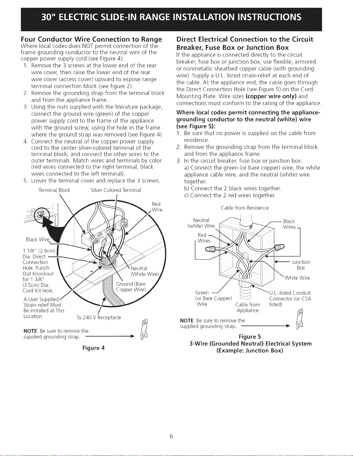
Four Conductor Wire Connection to Range
Where local codes does NOT permit connection of the
frame grounding conductor to the neutral wire of the
copper power supply cord (see Figure 4):
1. Remove the 3 screws at the lower end of the rear
wire cover, then raise the lower end of the rear
wire cover (access cover) upward to expose range
terminal connection block (see figure 2).
2. Remove the grounding strap from the terminal block
and from the appliance frame.
3. Using the nuts supplied with the literature package,
connect the ground wire (green) of the copper
power supply cord to the frame of the appliance
with the ground screw, using the hole in the frame
where the ground strap was removed (see Figure 4).
4. Connect the neutral of the copper power supply
cord to the center silver-colored terminal of the
terminal block, and connect the other wires to the
outer terminals. Match wires and terminals by color
(red wires connected to the right terminal, black
wires connected to the left terminal).
5. Lower the terminal cover and replace the 3 screws.
TerminalBlock SilverColoredTerminal
Red
.Wire
BlackWire
1 1/8" (2.9cm)f
Dia. Direct
m
Connection
Hole.Punch
Out Knockout
for 1 3/8"
(3.5cm)Dia.
Cord Kit Hole.
A User Supplied
Strain-relief Must
Be Installed at This
Location
To 240 V Receptacle
NOTE: Be sure to remove the
supplied grounding strap.
Figure 4
Direct Electrical Connection to the Circuit
Breaker, Fuse Box or Junction Box
If the appliance is connected directly to the circuit
breaker, fuse box or junction box, use flexible, armored
or nonmetallic sheathed copper cable (with grounding
wire). Supply a U.L. listed strain-relief at each end of
the cable. At the appliance end, the cable goes through
the Direct Connection Hole (see Figure 5) on the Cord
Mounting Plate. Wire sizes (copper wire only) and
connections must conform to the rating of the appliance.
Where local codes permit connecting the appliance-
grounding conductor to the neutral (white) wire
(see Figure 5):
1. Be sure that no power is supplied on the cable from
residence.
2. Remove the grounding strap from the terminal block
and from the appliance frame.
3. In the circuit breaker, fuse box or junction box:
a) Connect the green (or bare copper) wire, the white
appliance cable wire, and the neutral (white) wire
together.
b) Connect the 2 black wires together.
c) Connect the 2 red wires together.
Cable from Residence
NOTE: Be sure to remove the
supplied grounding strap.
Figure 5
3-Wire (Grounded Neutral) Electrical System
(Example: Junction Box)
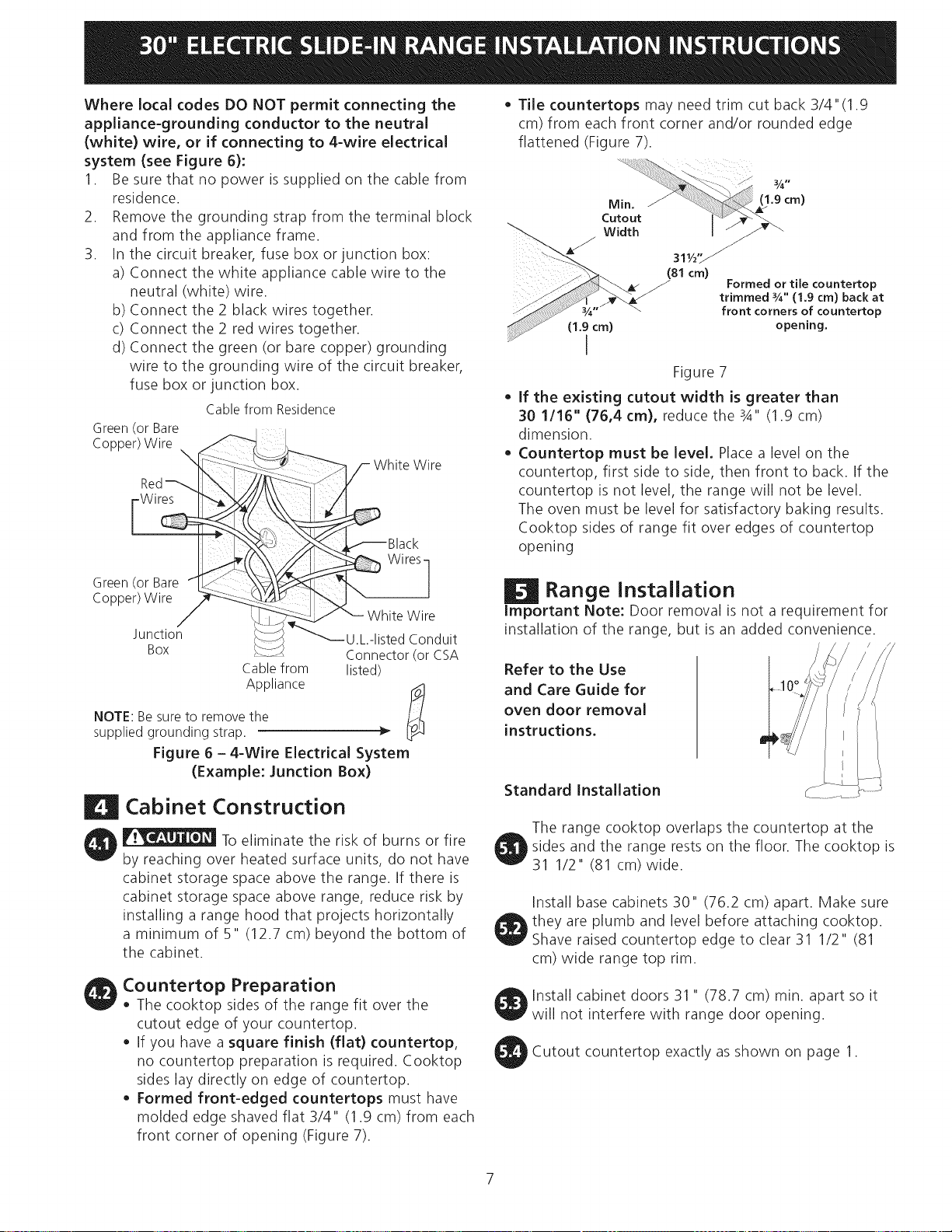
WherelocalcodesDONOTpermitconnectingthe
appliance-groundingconductorto theneutral
(white)wire, orif connectingto 4-wireelectrical
system(seeFigure6):
1. Besurethatnopowerissuppliedonthecablefrom
residence.
2. Removethegroundingstrapfromtheterminalblock
andfromtheapplianceframe.
3. Inthecircuitbreaker,fuseboxorjunctionbox:
a)Connectthewhiteappliancecablewiretothe
neutral(white)wire.
b)Connectthe2blackwirestogether.
c)Connectthe2redwirestogether.
d)Connectthegreen(orbarecopper)grounding
wiretothegroundingwireofthecircuitbreaker,
fuseboxorjunctionbox.
CablefromResidence
Green (or Bare
Copper)Wire _
Red_ b\ [-_
Green(or Bare fL:_
Copper)Wire _
Junction _......
Box
Cablefrom
Appliance
NOTE: Be sure to remove the
supplied grounding strap.
_ White Wire
_Black
Wires]
_,is T; uit
Connector(or CSA
listed)
Figure 6 - 4-Wire Electrical System
(Example: Junction Box)
Cabinet Construction
To eliminate the risk of burns or fire
by reaching over heated surface units, do not have
cabinet storage space above the range. If there is
cabinet storage space above range, reduce risk by
installing a range hood that projects horizontally
a minimum of 5" (12.7 cm) beyond the bottom of
the cabinet.
Countertop Preparation
• The cooktop sides of the range fit over the
cutout edge of your countertop.
• If you have a square finish (flat) countertop,
no countertop preparation is required. Cooktop
sides lay directly on edge of countertop.
• Formed front-edged countertops must have
molded edge shaved flat 3/4" (1.9 cm) from each
front corner of opening (Figure 7).
• Tile countertops may need trim cut back 3/4"(1.9
cm) from each front corner and/or rounded edge
flattened (Figure 7).
31,/,, ...--_
(81 cm)
Formed or tile countertop
trimmed _A" (1,9 cm) back at
front corners of countertop
(1.9 cm) opening,
I
Figure 7
If the existing cutout width is greater than
30 1/16" (76,4 cm), reduce the 3A" (1.9 cm)
dimension.
Countertop must be level, Place a level on the
countertop, first side to side, then front to back. If the
countertop is not level, the range will not be level.
The oven must be level for satisfactory baking results.
Cooktop sides of range fit over edges of countertop
opening
Range Installation
Important Note: Door removal is not a requirement for
installation of the range, but is an added convenience.
Refer to the Use
and Care Guide for
oven door removal
instructions.
Standard Installation
The range cooktop overlaps the countertop at the
sides and the range rests on the floor. The cooktop is
31 1/2" (81 cm)wide.
Install base cabinets 30" (76.2 cm) apart. Make sure
they are plumb and level before attaching cooktop.
Shave raised countertop edge to clear 31 1/2" (81
cm) wide range top rim.
Install cabinet doors 31 " (78.7 cm) min. apart so it
will not interfere with range door opening.
Cutout countertop exactly as shown on page 1.
7
For models equipped with Leveling Device:
Make sure the front leveling legs and the rear
leveling device are setup higher than the height of
the cabinet (shown on page 3).
install the anti-tip bracket at
this point before placing the range at its final
position. Follow the installation instructions on page
11 or 12 or on the anti-tip bracket template supplied
with the range.
To provide an optimum installation, the top surface
of the countertop must be level and flat (lie on the
same plane) around the 3 sides that are adjacent to
range cooktop. Proper adjustments to make the top
flat should be made or gaps between the countertop
and the range cooktop may occur.
To reduce the risk of damaging your
appliance, do not handle or manipulate it by the
ceramic glass. Manipulate with care.
Position range in front of the cabinet opening.
Make sure that the cooktop glass which overhangs
the countertop clears the countertop. If necessary,
raise the unit by lowering the leveling legs.
Slide the range into the cutout opening and center it
before leveling it.
Level the range (see section 6). The floor where
the range isto be installed must be level. Follow
the instructions under "Leveling the Range- Models
Equipped with Leveling Device".
Adjust leveling legs so that the underside of the
cooktop is sitting on the countertop. Carefully screw
in (refer to Leveling the range: Models equipped
with Leveling Device") the back leveling leg until
the cooktop glass overhang touches slightly the
countertop. Then carefully screw in the front two
leveling legs until the cooktop glass overhang
touches slightly the countertop.
For models equipped with Levelin Lg_L_e_g
only (no leveling device):
Make sure the four leveling legs (front and rear) are
setup higher than the height of the cabinet (shown
on page 3).
Install the anti-tip bracket at
this point before placing the range at its final
position. Follow the installation instructions on page
11 or 12 or on the anti-tip bracket template supplied
with the range.
To provide an optimum installation, the top surface
of the countertop must be level and flat (lie on the
same plane) around the 3 sides that are adjacent to
range cooktop. Proper adjustments to make the top
flat should be made or gaps between the countertop
and the range cooktop may occur.
To reduce the risk of damaging your
appliance, do not handle or manipulate it by the
ceramic glass. Manipulate with care.
Position range in front of the cabinet opening.
Make sure that the glass which overhangs the
countertop clears the countertop. If necessary, raise
the unit by lowering the leveling legs.
Level the range (see section 6). The floor where
O he range isto be installed must be level. Follow
the instructions under "Leveling the Range-Models
Equipped with Leveling Legs".
Slide the range into the cutout opening.
lf Accessories Needed
Installation With Backguard
A backguard kit can be ordered through a Sears Service
Center.The cutout depth (21 3/4" (55.2 cm) Min.,
22 1/8" (56.2 cm) Max.) needs to be increased to 24"
(61 cm) when installing a backguard
installation With End Panel
An end panel kit can be ordered through a Sears
Service Center.
installation With Side Panel
A side panels kit can be ordered through a Sears
Service Center.
Install cabinet doors 31 " (78.7 cm) min. apart so as not
to interfere with range door opening.
Leveling the Range
Models Equipped with Leveling Device
the range after installation in the cutout
opening.
1. Open the range drawer. The leveling screws control
the height of the rear leg.
2. Adjust the appliance legs as follows until the
underside of the cooktop surface is sitting level on
the countertop (Figure 8).
a.To adjust the front legs, use a wrench on
the leg base and turn clockwise to lower or
counterclockwise to raise.
b.To adjust the rear legs, use a ratchet or
a nutdriver and turn the leveling screws
counterclockwise to lower or clockwise to raise.
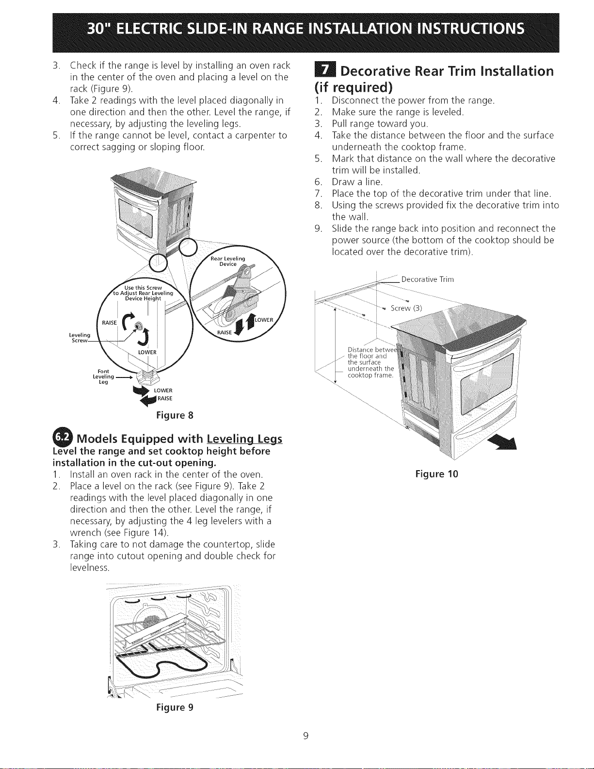
3. Checkif therangeislevelbyinstallinganovenrack
inthecenteroftheovenandplacingalevelonthe
rack(Figure9).
4. Take2readingswiththelevelplaceddiagonallyin
onedirectionandthentheother.Leveltherange,if
necessary,byadjustingthelevelinglegs.
5. Iftherangecannotbelevel,contactacarpenterto
correctsaggingorslopingfloor.
| Decorative
(if required)
1.
2.
3.
4.
,
,
7.
8.
,
Rear Trim Installation
Disconnect the power from the range.
Make sure the range is leveled.
Pull range toward you.
Take the distance between the floor and the surface
underneath the cooktop frame.
Mark that distance on the wall where the decorative
trim will be installed.
Draw a line.
Place the top of the decorative trim under that line.
Using the screws provided fix the decorative trim into
the wall.
Slide the range back into position and reconnect the
power source (the bottom of the cooktop should be
located over the decorative trim).
-- ..... " Decorative Trim
Leveling
Font
Leveling
Leg
_ LOWER
_ RAISE
Figure 8
Models Equipped with Leveling Leg_s
the range and set cooktop height before
installation in the cut-out opening.
1. Install an oven rack in the center of the oven.
2. Place a level on the rack (see Figure 9). Take 2
readings with the level placed diagonally in one
direction and then the other. Level the range, if
necessary, by adjusting the 4 leg levelers with a
wrench (see Figure 14).
3. Taking care to not damage the countertop, slide
range into cutout opening and double check for
levelness.
Screw (3)
Distance betwei
the floor and
the surface
underneath the
cooktop frame,
Figure 10
Figure 9
9
| Check Operation
Refer to the Use and Care Guide packaged with the
range for operating instructions and for care and
cleaning of your range.
Do not touch the elements. They may be
hot enough to cause burns.
Remove all packaging from the oven and the warmer
drawer (if equipped) before testing.
1. Operation of Surface Elements
Turn on each of the four surface elements and check to
see that they heat. Check the surface element indicator
light(s), if equipped.
2. Operation of Oven Elements
The oven is equipped with an electronic oven control. Each
of the functions has been factory checked before shipping.
However, it is suggested that you verify the operation
of the electronic oven controls once more. Refer to the
Electronic Oven Control Guide for operation. Follow the
instructions for the Clock, Timer, Bake, Broil, Convection
(some models) and Clean functions.
Bake-After setting the oven to 350% (177°C) for
baking, the lower element in the oven should become
red.
Broil-When the oven is set to BROIL,the upper element
in the oven should become red.
Clean-When the oven is set for a self-cleaning cycle, the
upper element should become red during the preheat
portion of the cycle. After reaching the self-cleaning
temperature, the lower element will become red.
Convection (some models)-When the oven is set to
CONV. BAKE/ROAST at 350% (177°C), the convection
element cycles on and off and the convection fan turns.
The convection fan will stop turning when the oven door
is opened during convection baking or roasting.
Warmer Drawer (some models)-Set the control knob
to HI and check to see the drawer is heating.
When All Hookups are Complete
Make sure all controls are left in the OFFposition.
Model and Serial Number Location
The serial plate is located on the oven front frame behind
the oven door (some models) or behind the drawer
(some models).
When ordering parts for or making inquiries about your
range, always be sure to include the model and serial
numbers and a lot number or letter from the serial plate
on your range.
Before You Call for Service
Read the Avoid Service Checklist and operating
instructions in your Use and Care Guide. It may save you
time and expense. The list includes common occurrences
that are not the result of defective workmanship or
materials in this appliance.
Refer to the warranty and service information in your Use
and Care Guide for Sears phone number and address.
Please call or write if you have inquiries about your range
product and/or need to order parts.
10
| Anti-Tip Brackets Installation
instructions- Ceramic Glass Cooktop only
Models Equipped with Leveling Device
To reduce the risk of tipping of the range,
the range must be secured to the floor by properly
installed anti-tip bracket and screws packed with the
range. Those parts are located in the oven. Failure to
install the anti-tip bracket will allow the range to tip over
if excessive weight is placed on an open door or if a child
climbs upon it. Serious injury might result from spilled
hot liquids or from the range itself.
Follow the instructions below to install the anti-tip
brackets.
If range is ever moved to a different location, the anti-
tip brackets must also be moved and installed with the
range.
Tools Required:
Adjustable Wrench
Ratchet
Drill & 1/8"(0,32 cm) bit
5/16" (0,8 cm) Nutdriver
Level
The anti-tip bracket attaches to the floor at the back of
the range to hold range rear center leg. When fastening
bracket to the floor, be sure that screws do not penetrate
electrical wiring or plumbing. The screws provided will
work in either wood or concrete.
d,_ Kitchen
¢0 Cabinet
Adl<_ i1__
_A:'I_ Toe Door
k¢
i CabinetPlate
, .. w/2"J -,
" -- (26.7 cm)
ANTI-TIP" "'-.
BRACKET
1. Draw a line on the floor (in front of the cutout)
aligned with the front of the cabinet (not with the
toe plate).
2. Unfold paper template and place it flat on the floor
with the front and side edges positioned exactly
on the cabinet line you just drew before. (Use the
diagram below to locate brackets if template is not
available (Figure 11)).
3. Mark on the floor the location of the 4 mounting
holes shown on the template. For easier installation,
3/16"(0,48 cm) diameter pilot holes 1/2"(1,27 cm)
deep can be drilled into the floor.
4. Remove template and place bracket on floor. Line up
holes in bracket with marks on floor and attach with
4 screws provided. Bracket must be secured to solid
floor (Figure 12). If attaching to concrete floor, first
drill 3/16"(0,48 cm) dia. pilot holes using a masonry
drill bit.
5. Be sure the 4 leveling legs are at the highest position
they can be.
6. Slide range into place making sure the range is
trapped by the anti-tip bracket (Figure 12). Lower
the range by adjusting the 4 leveling legs until the
underside of the cooktop is sitting level on the
countertop. Refer to "Leveling the Range" section.
7. After installation, verify that the anti-tip bracket is
engaged by grasping the top rear edge of the range
and carefully attempt to tilt it forward to make sure
range is properly anchored.
/
Floor Mount _ fl
Screws
Figure 12
Figure 11
SLIDE
BACK
11
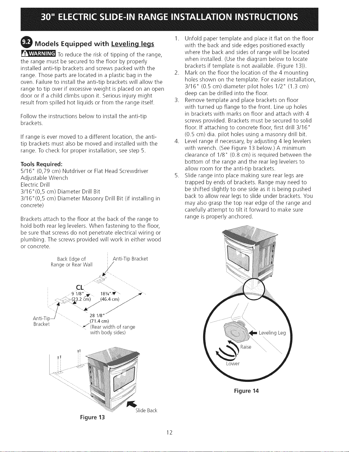
Models Equipped with Leveiin gLS
To reduce the risk of tipping of the range,
the range must be secured to the floor by properly
installed anti-tip brackets and screws packed with the
range. Those parts are located in a plastic bag in the
oven. Failure to install the anti-tip brackets will allow the
range to tip over if excessive weight is placed on an open
door or if a child climbs upon it. Serious injury might
result from spilled hot liquids or from the range itself.
Follow the instructions below to install the anti-tip
brackets.
If range is ever moved to a different location, the anti-
tip brackets must also be moved and installed with the
range. To check for proper installation, see step 5.
Tools Required:
5/16" (0,79 cm) Nutdriver or Flat Head Screwdriver
Adjustable Wrench
Electric Drill
3/16"(0,5 cm) Diameter Drill Bit
3/16"(0,5 cm) Diameter Masonry Drill Bit (if installing in
concrete)
Brackets attach to the floor at the back of the range to
hold both rear leg levelers. When fastening to the floor,
be sure that screws do not penetrate electrical wiring or
plumbing. The screws provided will work in either wood
or concrete.
BackEdgeof _' Anti-Tip Bracket
Rangeor RearWall //
_-9 1/8" ._. 18W'-_ - /._r".
_Z-.,_i_(;_3.2._.y..__m) (46.4 cm) /
n I,, I.p "'"- (71.4 cm)
iJracKet -. J ..... r
-- [Kearw_dthOTrange
with bodysides)
1. Unfold paper template and place it flat on the floor
with the back and side edges positioned exactly
where the back and sides of range will be located
when installed. (Use the diagram below to locate
brackets if template is not available. (Figure 13)).
2. Mark on the floor the location of the 4 mounting
holes shown on the template. For easier installation,
3/16" (0.5 cm) diameter pilot holes 1/2" (1.3 cm)
deep can be drilled into the floor.
3. Remove template and place brackets on floor
with turned up flange to the front. Line up holes
in brackets with marks on floor and attach with 4
screws provided. Brackets must be secured to solid
floor. If attaching to concrete floor, first drill 3/16"
(0.5 cm) dia. pilot holes using a masonry drill bit.
4. Level range if necessary, by adjusting 4 leg levelers
with wrench. (See Figure 13 below.) A minimum
clearance of 1/8" (0.8 cm)is required between the
bottom of the range and the rear leg levelers to
allow room for the anti-tip brackets.
5. Slide range into place making sure rear legs are
trapped by ends of brackets. Range may need to
be shifted slightly to one side as it is being pushed
back to allow rear legs to slide under brackets. You
may also grasp the top rear edge of the range and
carefully attempt to tilt it forward to make sure
range is properly anchored.
Figure 13
SlideBack
Figure 14
12
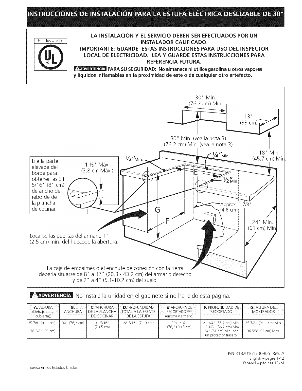
Estados Unidos
LA INSTALACION Y EL SERVICIO DEBEN SER EFECTUADOS POR UN
INSTALADOR CAUFICADO.
IMPORTANTE: GUARDE ESTAS INSTRUCCIONES PARA USO DEL INSPECTOR
LOCAL DE ELECTRICIDAD. LEA Y GUARDE ESTAS INSTRUCCIONES PARA
REFERENCIA FUTURA.
PAPA SU SEGURIDAD: No almanece ni utilice gasolina u otros vapores
y liquidos inflamables en la proximidad de este o de cualquier otto artefacto.
Lije la parte
elevade del
borde para
obtener las 31
5/16" (81 cm)
de ancho del
reborde de
la plancha
de codnar.
1//2 HlVli n.
G
30" Min.
_(76.2 cm) Min.
18" Min.
Min. (45.7 cm) Mir
Localise las puertas del armario 1"
(2.5 cm) min. del huecode la abertura.
La caja de empalmes o el enchufe de conexion con la tierra
deberia situarse de 8" a 17" (20.3 - 43.2 cm) del armario derecho
y de 2" a 4" (5.1-10.2 cm) del suelo.
}fox. 1 7/8"
(4.8 cm):
oo
24" Min.
(61 cm)
No instale la unidad en el gabinete si no ha leido esta pagina.
AALTURA B.' €:ANCHURA" D: PROFUNDIDAD
(Debajo de la ANCHURA DELA PLANCHA TOTAL ALA FRENTE
cubierta)) ' DE COCINAR DE LA ESTUFA
35 7/8" (91,1 cm)- 30" (76,2 cm) 31 5/16" 28 5/16" (71,9 cm)
(79.5 cm)
36 5/8" (93 cm)
E.ANCHURADE F. PROFUNDIDAD DE I G: ALTURA DEL
RECORTADO_**t I RECORTADO MOSTRADOR
(encimay armario) i i
30_+1/16" 21 3/4" (55,2 cm) Min.
(76,2_+0,15 cm) 22 1/8" (56,2 cm) Max
24" (61 cm) Min. con
un protector trasero.
35 7/8" (91,1 cm) Min.
36 5/8" (93 cm) Max.
Impreso en los Estados Unidos
P/N 318201617 (0905) Rev. A
English - pages 1-12
Espahol - p_iginas 13-24
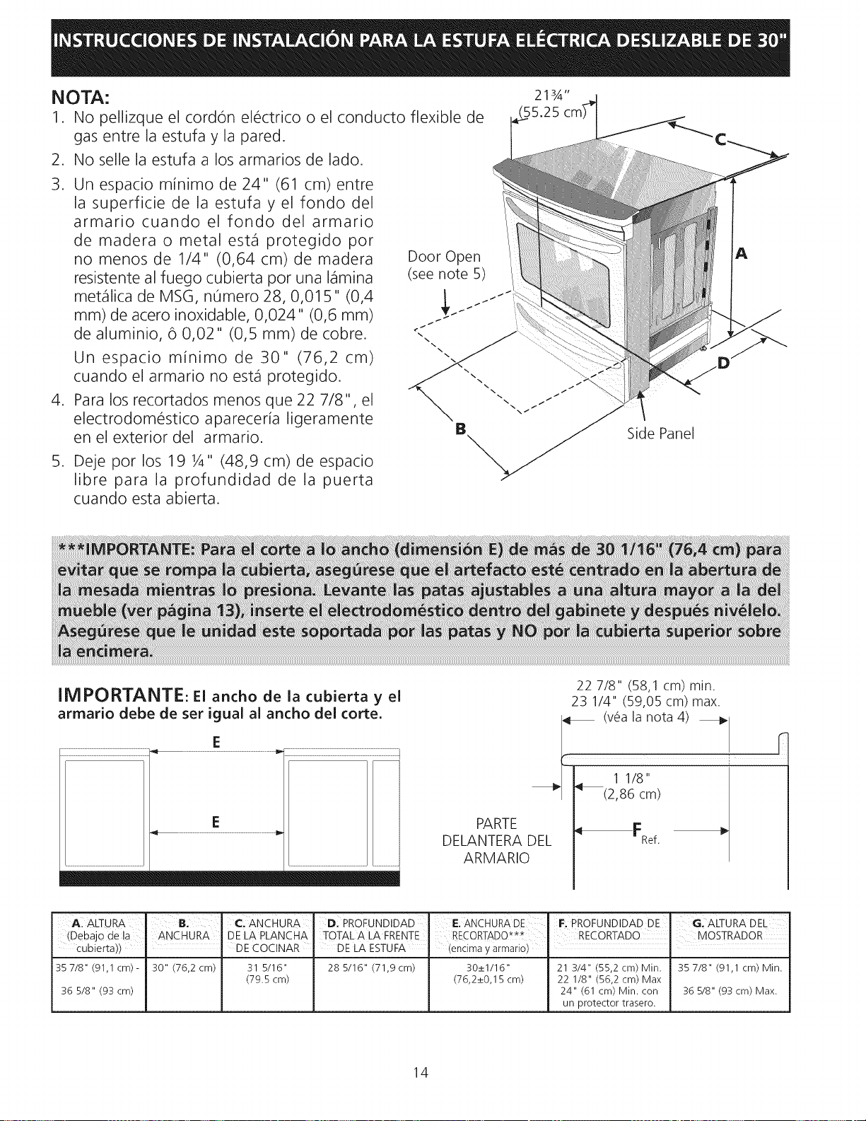
NOTA:
1. No pellizque el cordon electdco o el conducto flexible de
gas entre la estufa y la pared.
2. No selle la estufa a los armados de lado.
3. Un espado minimo de 24" (61 cm) entre
la superfide de la estufa y el fondo del
armado cuando el fondo del armario
de madera o metal est_fl protegido por
no menos de 1/4" (0,64 cm) de madera
resistente al fuego cubierta por una I_flmina
met_fllica de MSG, n0mero 28, 0,015" (0,4
ram) de acero inoxidable, 0,024" (0,6 ram)
de aluminio, 6 0,02" (0,5 ram) de cobre.
Un espacio minimo de 30" (76,2 cm)
cuando el armado no est,1 protegido.
4. Para los recortados menos que 22 7/8", el
electrodomestico apareceria ligeramente
en el exterior del armario.
5. Deje por los 19 1A" (48,9 cm) de espado
libre para la profundidad de la puerta
cuando esta abierta.
A
IMPORTANTE: El ancho de la cubierta y el
armario debe de ser igual al ancho del torte.
E
E
22 7/8" (58,1 cm) rain.
23 1/4" (59,05 cm) max.
i (v_a la nota 4) _
_'| _(2,86 cm) /
/
DELANPIRTE DEL '_FRef. I,_
ARMARIO
A: ALTURA ' 'B. 1:::.ANCHURA D: PROFUNDIDAD
(Debajo dela ANCHURA DELA PLANCHA TOTALA LA FRENTE
c | I
ubierta)) DECOCINAR DE LA ESTUFA
35 7/8" (91,1 cm)- 30" (76,2 cm) 31 5/16" 28 5/16" (71,9 cm)
(79.5 cm)
36 5/8" (93 cm)
E;ANCHURADE
RECORTADO***
(encimay armario)
F: PROFUNDIDAD DE' G. ALTURA DEL
30_+1/16" 21 3/4" (55,2 cm) Min. 35 7/8" (91,1 cm) Min.
(76,2_+0,15 cm) 22 1/8" (56,2 cm) Max
24" (61 cm) Min. con 36 5/8" (93 cm) Max.
un protector trasero.
14
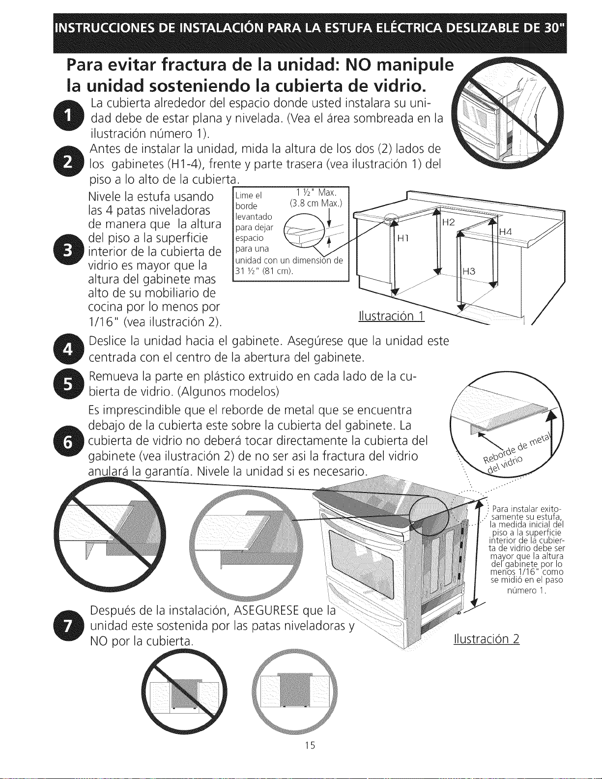
Para evitar fractura de la unidad: NO manipule
la unidad sosteniendo la cubierta de vidrio.
La cubierta alrededor del espacio donde usted instalara su uni- _
dad debe de estar plana y nivelada. (Vea el _irea sombreada en la
k
ilustracion n0mero 1).
Antes de instalar la unidad, mida la altura de los dos (2)lados de
los gabinetes (H1-4), frente y parte trasera (vea ilustracion 1) del
piso a Io alto de la cubierta.
Nivele la estufa usando
las 4 patas niveladoras
de manera que la altura
del piso a la superficie
interior de la cubierta de
vidrio es mayor que la
altura del gabinete mas
alto de su mobiliario de
cocina por Io menos por
1/16" (vea ilustracion 2).
Lime el 1 1/2" Max.
horde (3.8 cm Max.)
levantado
para dejar
espacio
)ara una
unidad con un dimensi6n
31 Y2" (81 cm).
Ilustracion 1
Deslice la unidad hacia el gabinete. Aseg0rese que la unidad este
centrada con el centro de la abertura del gabinete.
Remueva la parte en pl_istico extruido en cada lado de la cu-
bierta de vidrio. (Algunos modelos)
Esimprescindible que el reborde de metal que se encuentra
debajo de la cubierta este sobre la cubierta del gabinete. La
cubierta de vidrio no deber_i tocar directamente la cubierta del
gabinete (vea ilustracion 2) de no ser asi la fractura del vidrio
anular_i la garantfa. Nivele la unidad si es necesario.
! Para instalar exito-
.: samente su estufa,
la medida inicial del
piso a lasuperficie
interior de la cubier-
ta de vidrio debe ser
_qa.yor.que la altura
el gablnete por Io
menos 1/16" como
se midi6 en el paso
nOmero 1.
Despues de la instalacion, ASEGURESE que
unidad este sostenida por las patas niveladoras y
NO por la cubierta.
Ilustracion 2
15
Notas irnportantes para el instalador
1. Lea todas las instrucciones antes de instalar la cocina.
2. Retire todo material de empaquetado del homo y de la ga-
veta de entibiado antes de conectar el suministro electrico
a la cocina.
3. Observe todo codigo o reglamento.
4. AsegOrese de dejar estas instrucciones con el consumidor
Nota importante para el consurnidor
Mantenga estas instrucciones con el manual del usuario para
futuras referencias.
INSTRUCCIONES DE
SEGURIDAD IMPORTANTES
• Asegurese que su cocina est_ instalada y conectada
adecuadarnente a tierra pot un instalador calificado
o un tecnico de servicio.
• Este cocina debe set electricarnente puesta a tierra
de acuerdo con los codigos locales o, en su ausencia,
con el C6digo Electrico Nacional ANSI/NFPA No, 70--
ultirna edicion en los Estados Unidos.
• La instalacion de electrodomesticos destinados para
casas (movibles) deben conformarse con la Manufactured
Home Construction and Safety Standard, t[tulo 24CFR,
parte 3280 [antiguamente la Federal Standard for Mobile
Home Construction and Safety, t[tulo 24, HUD (parte
280)] o cuando este codigo no se aplica, la Standard for
Manufactured Home Installation 1982 (Manufactured
Home sites, communities and setups); ANSIZ225.1/NFPA
501A- 01tima edicion o con codigos locales en los Estados
Unidos.
I!_ Pisar, apoyarse o sentarse en las
puertas o los cajones de la cocina pueden causar
graves heridas y tarnbien da_ar la cocina.
• No coloque cosas que atraigan a los ni_os sobre los
gabinetes encirna de la cocina. Los nihos podrfan sufrir
quemaduras tratando de alcanzarlos.
• Para evitar riesgos de quernaduras o incendios
al tocar superficies calientes, se deben evitar los
arrnarios sobre la superficie de los quernadores,
Si existe un armario, se pueden reducir los riesgos
instalando una campana que se extienda horizontalmente
en un m[nimo de 5" pot sobre la parte inferior de los
armarios.
• No use el homo corno espacio de alrnacenarniento.
Fsto crea una situacion muy peligrosa.
• Nunca use su cocina para calentar la pieza. El uso
prolongado de la cocina sin ventilacion adecuada puede
set peligroso.
• No guarde o use gasolina u otros vapores
inflarnables y liquidos cerca de este o cualquier otro
electrodomestico. Esto podrfa causar una explosion o un
incendio.
• Vuelva a prograrnar todos los controles a la posici6n
"off" (apagado) despues de haber utilizado el
conteo contador autorn_tico,
PARA LOS MODELOS CON AUTO-UMPIEZA:
• Retire el rostisador, la cornida y otros utensilios
antes de auto-limpiar el horno. Limpie todo exceso de
derrames. Siga las instrucciones para la pre-limpieza en el
Manual del usuario.
F_ Nunca deje a los ni_os solos o sin
cuidado en el area donde el electrodornestico et_ en
uso. A medida que los nihos crezcan, enseheles el uso
adecuado de los electrodomesticos. Nunca deje la puerta
del homo abierta cuando la cocina este sin supervision.
Todas las cocinas pueden inclinarse.
Esto puede provocar lesiones
personales
Instale el dispositivo anti-
indinacion que viene con la cocina.
Para reducir el riesgo de indinacion
de la cocina, esta debe estar ajustada
correctamente con las fijaciones anti
indinacion que vienen con la cocina.
Para verificar si las fijaciones estan
instaladas adecuadamente, agarre la parte
superior del borde posterior de la cocina y inclinela
hacia adelante cuidadosamente para asegurar que
la cocina esta sujetada.
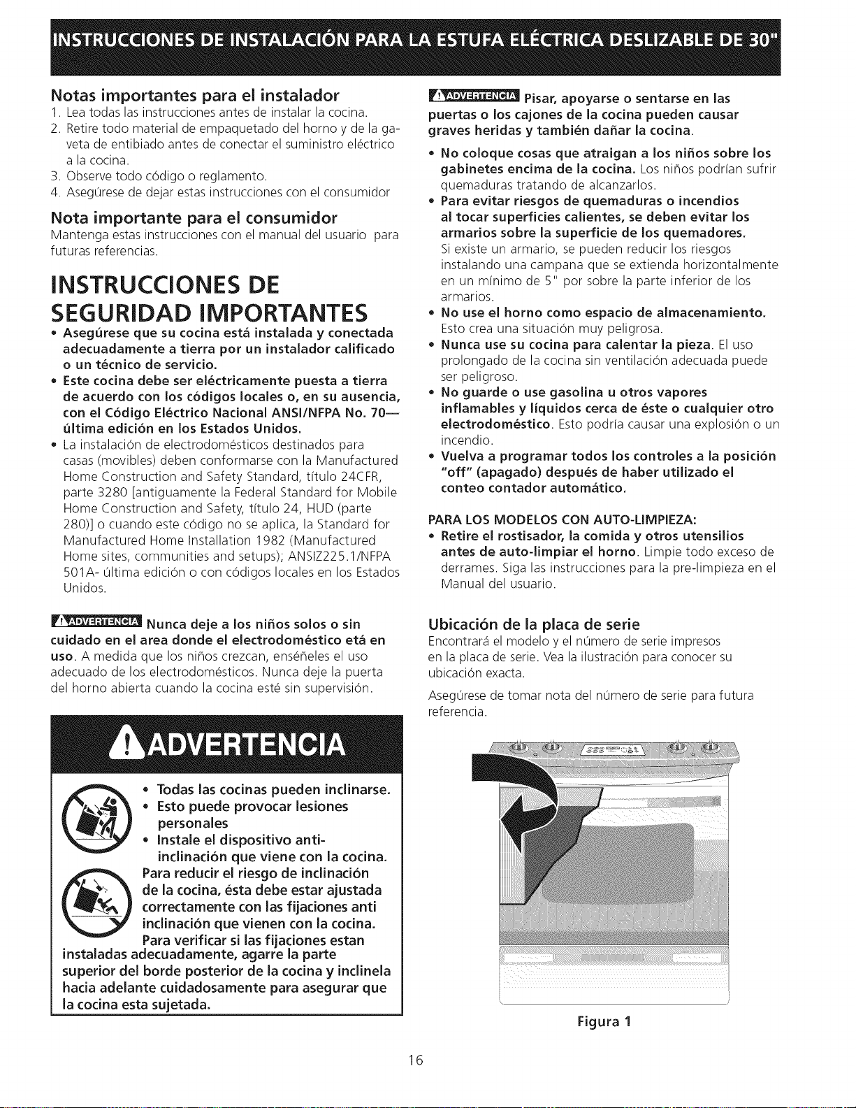
Ubicaci6n de la plata de serie
Encontrar_iel modelo y el n0mero de serie impresos
en la placa de serie. Vea la ilustracion para conocer su
ubicacion exacta.
Aseg0rese de tomar nota del n0mero de serie para futura
referencia.
Figura 1
16
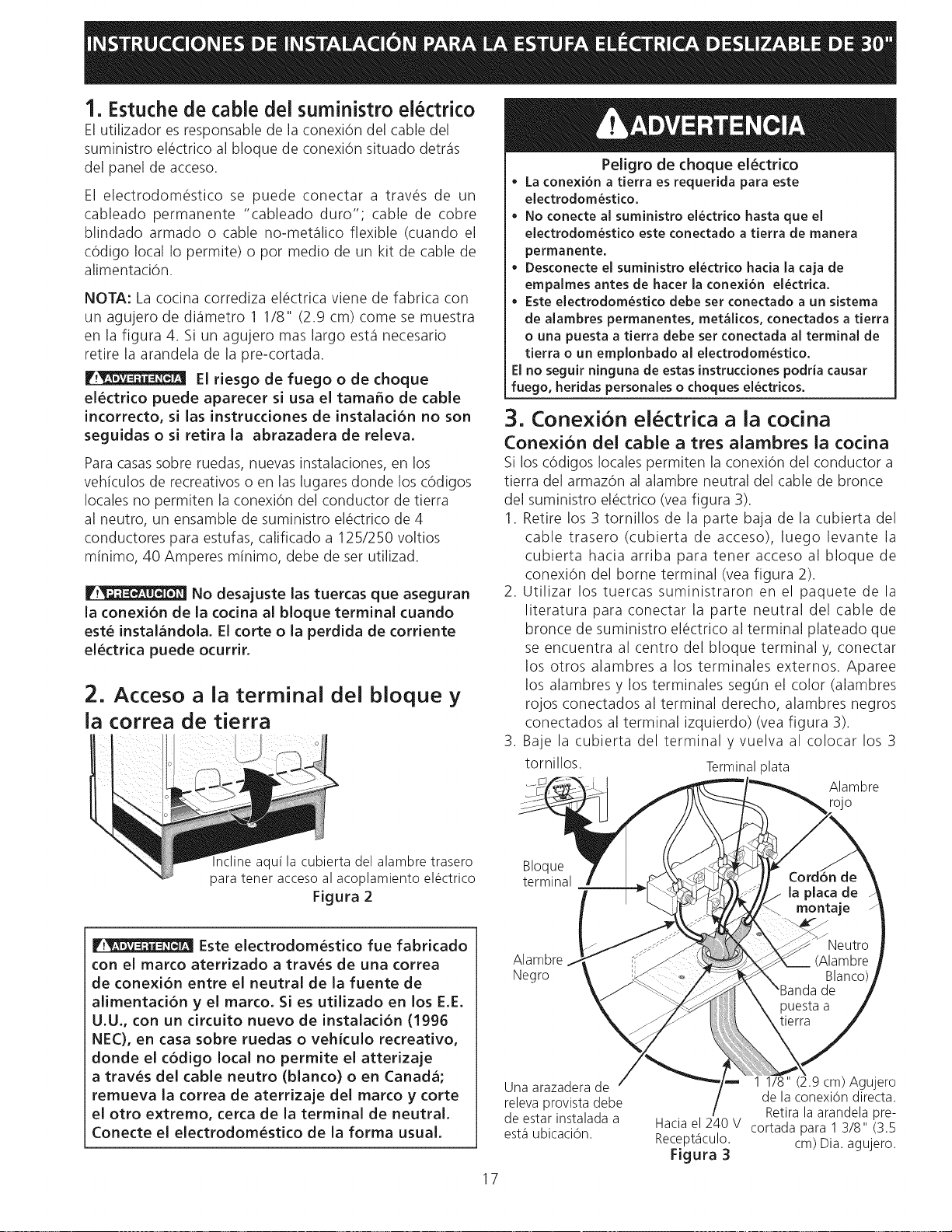
1. Estuche de cable del suministro electrico
El utilizador es responsable de la conexiOn del cable del
suministro el@ctricoal bloque de conexi6n situado detr_is
del panel de acceso.
El electrodom_stico se puede conectar a trav_s de un
cableado permanente "cableado duro"; cable de cobre
blindado armado o cable no-met_ilico flexible (cuando el
c6digo local Io permite) o por medio de un kit de cable de
alimentaciOn.
NOTA: La cocina corrediza el_ctrica viene de fabrica con
un agujero de di_imetro 1 1/8" (2.9 cm) come se muestra
en la figura 4. Si un agujero mas largo est,1necesario
retire la arandela de la pre-cortada.
F_ El riesgo de fuego o de choque
el6ctrico puede aparecer si usa el tama_o de cable
incorrecto, si las instrucdones de instalaci6n no son
seguidas o si retira la abrazadera de releva.
Para casassobre ruedas, nuevas instalaciones, en los
vehiculos de recreativos o en las lugares donde los c6digos
locales no permiten la conexi6n del conductor de tierra
al neutro, un ensamble de suministro el_ctrico de 4
conductores para estufas, calificado a 125/250 voltios
minimo, 40 Amperes minimo, debe de ser utilizad.
No desajuste las tuercas que aseguran
la conexi6n de la codna al bloque terminal cuando
est6 instalandola. Elcorte o la perdida de corriente
electrica puede ocurrir.
2. Acceso a la terminal del bloque y
la correa de tierra
Peligro de choque el6ctrico
• La conexi6n a tierra es requerida para este
electrodom6stko.
No conecte al suministro electrko hasta que el
electrodomestko este conectado a tierra de manera
permanente.
• Desconecte el suministro electrico hada la caja de
empalmes antes de hater la conexi6n electrica.
• Este electrodomestico debe set conectado a un sistema
de alambres permanentes, met&licos, conectados a tierra
o una puesta a tierra debe set conectada al terminal de
tierra o un emplonbado al electrodomestico.
El no seguir ninguna de estas instrucciones podria causar
fuego, heridas personales o choques electricos.
3, Conexi6n el6ctrica a la cocina
Conexi6n del cable a tres alambres ia cocina
Si los cOdigos locales permiten la conexiOn del conductor a
tierra del armaz6n al alambre neutral del cable de bronce
del suministro el@ctrico(vea figura 3).
1. Retire los 3 tornillos de la parte baja de la cubierta del
cable trasero (cubierta de acceso), luego levante la
cubierta hacia arriba para tener acceso al bloque de
conexi6n del borne terminal (vea figura 2).
2. Utilizar los tuercas suministraron en el paquete de la
literatura para conectar la parte neutral del cable de
bronce de suministro el@ctricoal terminal plateado que
se encuentra al centro del bloque terminal y, conectar
los otros alambres a los terminales externos. Aparee
los alambres y los terminales segOn el color (alambres
rojos conectados al terminal derecho, alambres negros
conectados al terminal izquierdo) (vea figura 3).
3. Bale la cubierta del terminal y vuelva al colocar los 3
tornillos. Terminalplata
Alambre
rojo
qcline aqu[la cubierta del alambre trasero
para tenet acceso al acoplamiento electrico
Figura 2
Bloque
terminal
Este electrodom6stico fue fabricado
con el marco aterrizado a traves de una correa
de conexion entre el neutral de la fuente de
alimentad6n y el marco. Si es utilizado en los E.E.
U.U., con un drcuito nuevo de instalaci6n (1996
NEC), en casa sobre ruedas o vehiculo recreativo,
donde el c6digo local no permite el atterizaje
a traves del cable neutro (blanco) o en Canad&,
remueva la correa de aterrizaje del marco y torte
el otro extremo, cerca de la terminal de neutral.
Conecte el electrodomestico de la forma usual.
Alambre
Negro
Una arazadera de
releva provista debe
de estar instalada a
est,1ubicaci6n.
17
Hacia el 240 V
Recept_iculo.
Figura 3
1 1/8" .9 cm) Agujero
de la conexi6n directa.
Retira la arandela pre-
cortada para 1 3/8" (3.5
cm) Dia. agujero.
Conexion del cable de cuatro conductores a
ia cocina.
1. Retire los 3 tornillos de la parte baja de la cubierta
del cable trasero, luego levante la cubierta hacia
arriba para tener acceso (cubierta de acceso) al
bloque de conexi0n del borne terminal (vea figura 2).
2. Retire la correa de la base del bloque terminal y del
armaz6n del electrodom_stico. Retenga el tornillo de
la base.
3. Utilizar los tuercas suministraron en el paquete de la
literatura para conectar el alambre de tierra (verde)
del cable de bronce del suministro el_ctrico al
armaz6n del electrodom_stico con el tornillo de la
base, usando el hoyo del armaz6n por donde retir6
la correa de la base (vea figura 4).
4. Conecte el alambre neutral (blanco) del cable de
cobre del suministro el_ctrico al terminal plateado
del centro del bloque terminal y, conecte los otros
alambres a los terminales externos.
5. Baje la cubierta del terminal y vuelva al colocar los 3
tornillos.
Bloque terminal Terminal plata
Alambre
Alambre
Nec
1 1/8" (2.9 cm)
Dia. A,
de la conexi6n
directa. Retira
la arandela pre-
cortada para 1
318" (3.5 cm)
dia. agujero.
Una arazadera de
releva provista debe de
estar instalada a est,1
ubicaci6n.
Hacia el 240 V recept_iculo
NOTA: Asegurese de quitar
la banda de puesta a tierra
provista.
Figura 4
Conexi6n el6ctrica directa ai cortacircuito, a
ia caja de fusibles o ia caja de empalmes
Si el aparato est_Sconectado directamente al cortacircuito,
a la caja de fusibles o a la caja de empalmes, use un cable
blindado flexible o no met_ilico recubierto de cobre (con
alambre a tierra). Provee una abrazadera releva de anclaje
hom61ogo ULa cada extremidad del cable. A la extremidad
del electrodom_stico, el cable pase a trav_s del agujero
de la conexi6n directa (ver figura 5) en el cord6n de la
placa de montaje. El tamaflo de los alambres (alambre de
cobre solamente) y las conexiones deben estar conforme
al r_gimen del electrodom_stico.
Donde los c6digos locales permitan conectar el
conductor de puesta a tierra del electrodom6stico al
neutral (blanco) (vea figura 5):
1. Desconecte el suministro el_ctrico.
2. Enel cortacircuito, la caja de fusibles o la caja de
empalmes:
a) Conecte el alambre verde (o cobre desnudo), el
alambre blanco del cable del electrodom_stico y el
alambre neutral (blanco)juntos.
b) Conecte los dos alambres negros juntos.
c) Conecte los dos alambres rojos juntos.
Cable de la fuente de
alimentaciOn
Alambreneutro "_-_"_t
(blanco)I_ _:_._---!
Alamb!es--,,,?"
r°J°st_,' ,k_/_
dAleanudos_/ _:_
o verdes "_
Cablede la
estufa
NOTA: Asegurese de quitar
la banda de puesta a tierra
provista.
Figura 5
Alambres
negros
]_--- Caja de
_ empalmes
.I "Alambre blanco
Conductor de
uni6n listado-UL
(listado-CSA)
18
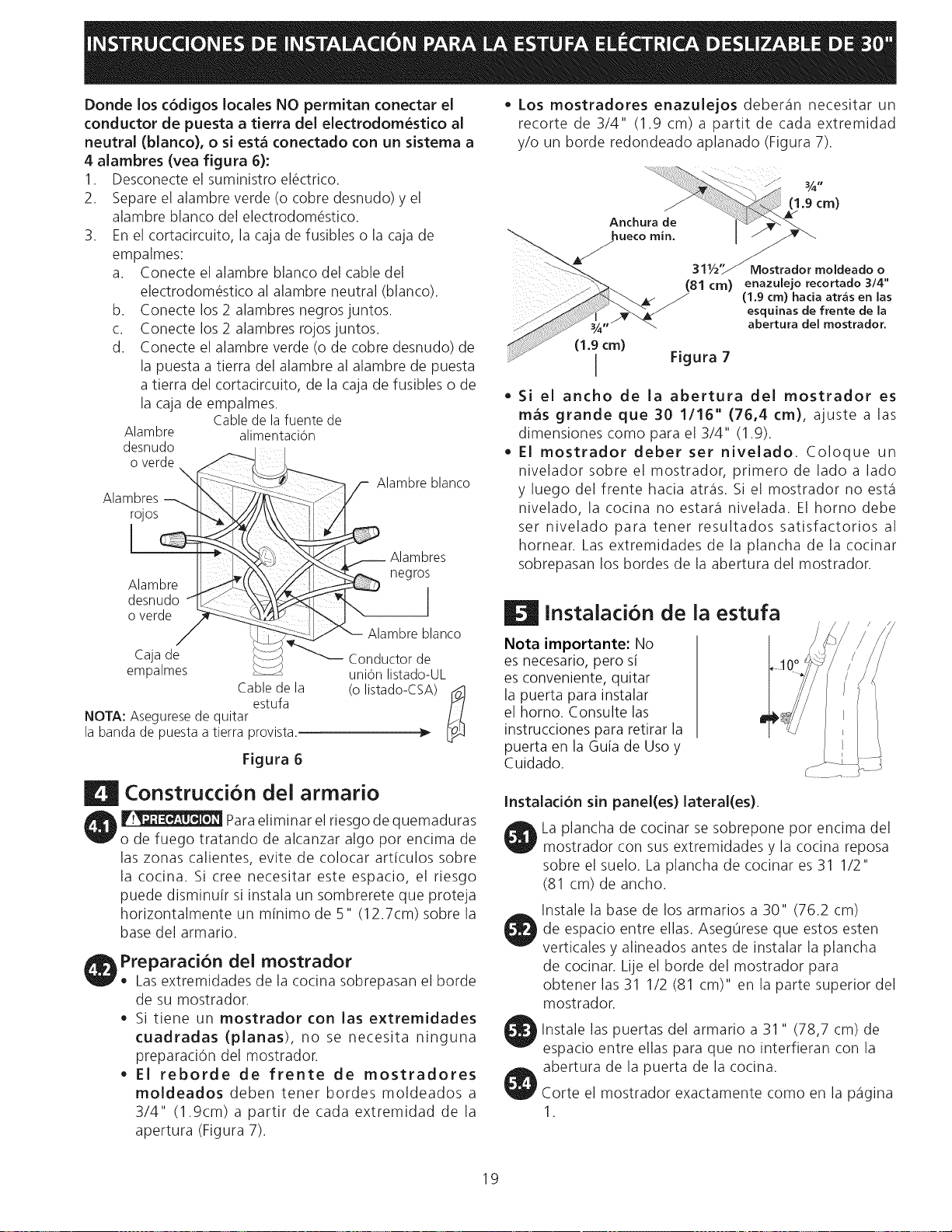
Dondelosc6digoslocalesNOpermitan conectar el
conductor de puesta a tierra del electrodom_stico al
neutral (blanco), o si est_ conectado con un sistema a
4 alambres (vea figura 6):
1. Desconecte el suministro el_ctrico.
2. Separe el alambre verde (o cobre desnudo) y el
alambre blanco del electrodom_stico.
3. En el cortacircuito, la caja de fusibles o la caja de
empalmes:
a. Conecte el alambre blanco del cable del
electrodom_stico al alambre neutral (blanco).
b. Conecte los 2 alambres negros juntos.
c. Conecte los 2 alambres rojos juntos.
d. Conecte el alambre verde (o de cobre desnudo) de
la puesta a tierra del alambre al alambre de puesta
a tierra del cortacircuito, de la caja de fusibles o de
la caja de empalmes.
Cablede lafuente de
Alambre alimentaciOn
desnudo
o verde
Alambres_ rh\ --_ :_
rojos
Alambre X,
desnudo qk. / _ )_V_
overde __ ,_
,/
Cajade i_::L_
empalmes
Cablede la
estufa
NOTA: Asegurese de quitar
la banda de puesta atierra provista.
_-'_'-_ /- Alambreblanco
1
_ Alambres
negr°i
_ Alambre blanco
_'"_ Conductorde
uni6n listado-UL
(o listado-CSA)__
Figura 6
• Los mostradores enazulejos deber_in necesitar un
recorte de 3/4" (1.9 cm) a partit de cada extremidad
y/o un horde redondeado aplanado (Figura 7).
...... %°,
(1.9cm)
Anch
......_ 311/IY Mostrador moldeado o
_--'_> (81 cm) enazulejo recortado 3/4"
/ (1,9 cm) hacia atras en las
esquinas de frente de la
abertura del mostrador.
(1.9 cm) Figura 7
/
Si el ancho de la abertura del mostrador es
mas grande que 30 1/16" (76,4 cm), ajuste a las
dimensiones como para el 3/4" (1.9).
El mostrador deber set nivelado. Coloque un
nivelador sobre el mostrador, primero de lado a lado
y luego del frente hacia atr_is. Si el mostrador no est,1
nivelado, la cocina no estate1nivelada. El homo debe
ser nivelado para tener resultados satisfactorios al
hornear. Las extremidades de la plancha de la cocinar
sobrepasan los hordes de la abertura del mostrador.
| Instalacion de la estufa
Nota importante: No
es necesario, pero si
es conveniente, quitar
la puerta para instalar
el horno. Consulte las
instrucciones para retirar la
puerta en la Guia de Uso y
Cuidado.
| Construccion del armario
,_ Para eliminar el riesgo de quemaduras
o de fuego tratando de alcanzar algo por encima de
las zonas calientes, evite de colocar articulos sobre
la cocina. Si cree necesitar este espacio, el riesgo
puede disminuir si instala un sombrerete que proteja
horizontalmente un minimo de 5" (12.7cm) sobre la
base del armario.
Preparacion del mostrador
Lasextremidades de la cocina sobrepasan el horde
de su mostrador.
• Si tiene un mostrador con las extremidades
cuadradas (planas), no se necesita ninguna
preparaci6n del mostrador.
El reborde de frente de mostradores
moldeados deben tener hordes moldeados a
3/4" (1.9cm) a partir de cada extremidad de la
apertura (Figura 7).
Instalaci6n sin panel(es) lateral(es).
La plancha de cocinar se sobrepone por encima del
mostrador con sus extremidades y la cocina reposa
sobre el suelo. La plancha de cocinar es 31 1/2"
(81 cm) de ancho.
Instale la base de los armarios a 30" (76.2 cm)
de espacio entre elias. Aseg0rese que estos esten
verticales y alineados antes de instalar la plancha
de cocinar. Lije el horde del mostrador para
obtener las 31 1/2 (81 cm)" en la parte superior del
mostrador.
Instale las puertas del armario a 31 " (78,7 cm) de
espacio entre elias para que no interfieran con la
abertura de la puerta de la cocina.
Corte el mostrador exactamente como en la p_igina
1.
19
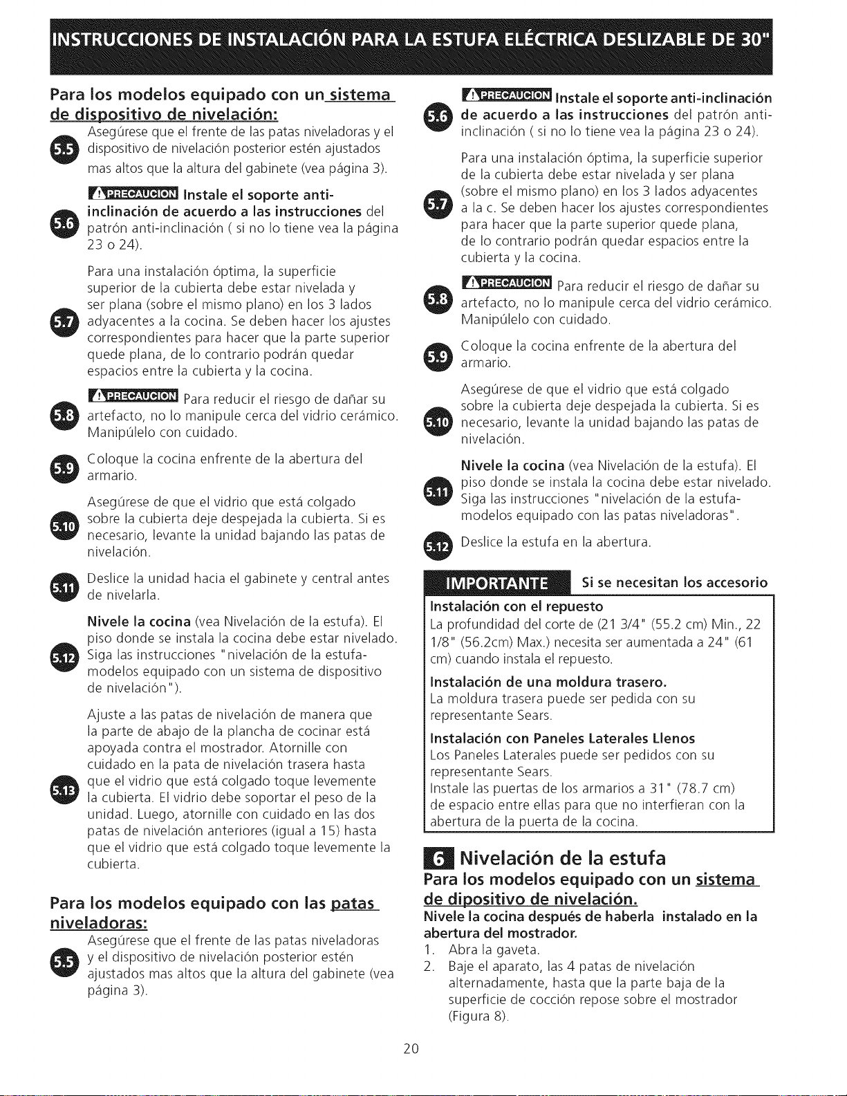
Para los modelos equipado con un sistema
de dispositivo de nivelaci6n:
Aseg0rese que el frente de las patas niveladoras y el
dispositivo de nivelaciOn posterior est_n ajustados
mas altos que la altura del gabinete (vea p_igina 3).
Instale el soporte anti-
inclination de acuerdo alas instrucdones del
patron anti-indinaci0n ( si no Io tiene vea la p_igina
23 o 24).
Para una instalaciOn Optima, la superficie
superior de la cubierta debe estar nivelada y
set plana (sobre el mismo piano) en los 3 lados
adyacentes a la cocina. Se deben hacer los ajustes
correspondientes para hacer que la parte superior
quede plana, de Io contrario podr_in quedar
espacios entre la cubierta y la cocina.
Para reducir el riesgo de dahar su
artefacto, no Io manipule cerca del vidrio cer_imico.
Manip01elo con cuidado.
Coloque la cocina enfrente de la abertura del
armario.
AsegOrese de que el vidrio que est,1colgado
sobre la cubierta deje despejada la cubierta. Si es
necesario, levante la unidad bajando las patas de
nivelaci6n.
Instale el soporte anti=inclinacion
de acuerdo alas instrucciones del patron anti-
inclinaciOn ( si no Io tiene vea la p_igina 23 o 24).
Para una instalaciOn Optima, la superficie superior
de la cubierta debe estar nivelada y set plana
(sobre el mismo piano) en los 3 lados adyacentes
a la c. Se deben hacer los ajustes correspondientes
para hacer que la parte superior quede plana,
de Io contrario podr_in quedar espacios entre la
cubierta y la cocina.
Para reducir el riesgo de dahar su
artefacto, no Io manipule cerca del vidrio cer_imico.
Manip01elo con cuidado.
Coloque la cocina enfrente de la abertura del
armario.
AsegOrese de que el vidrio que est,1colgado
sobre la cubierta deje despejada la cubierta. Si es
necesario, levante la unidad bajando las patas de
nivelaci6n.
Nivele la codna (vea Nivelaci6n de la estufa). El
piso donde se instala la cocina debe estar nivelado.
Siga las instrucciones "nivelaci6n de la estufa-
modelos equipado con las patas niveladoras".
Deslice la estufa en la abertura.
Deslice la unidad hacia el gabinete y central antes
de nivelarla.
Nivele la codna (vea Nivelaci0n de la estufa). El
piso donde se instala la cocina debe estar nivelado.
Siga las instrucciones "nivelaciOn de la estufa-
modelos equipado con un sistema de dispositivo
de nivelaciOn").
Ajuste alas patas de nivelaciOn de manera que
la parte de abajo de la plancha de cocinar est,1
apoyada contra el mostrador. Atornille con
cuidado en la pata de nivelaciOn trasera hasta
que el vidrio que est,1colgado toque levemente
la cubierta. El vidrio debe soportar el peso de la
unidad. Luego, atornille con cuidado en las dos
patas de nivelaciOn anteriores (igual a 15) hasta
que el vidrio que est,1colgado toque levemente la
cubierta.
Para los modelos equipado con ias patas
niveladoras:
AsegOrese que el frente de las patas niveladoras
y el dispositivo de nivelaciOn posterior est_n
ajustados mas altos que la altura del gabinete (vea
p_igina 3).
Si se necesitan los accesorio
Instalaci6n con el repuesto
La profundidad del corte de (21 3/4" (55.2 cm) Min., 22
1/8" (56.2cm) Max.) necesita set aumentada a 24" (61
cm) cuando instala el repuesto.
Instaladon de una moldura trasero.
La moldura trasera puede set pedida con su
representante Sears.
Instaladon con Paneles Laterales Llenos
Los Paneles Laterales puede set pedidos con su
representante Sears.
Instale las puertas de los armarios a 31 " (78.7 cm)
de espacio entre elias para que no interfieran con la
abertura de la puerta de la cocina.
Nivelacion de la estufa
Para los modelos equipado con un sistema
de dipositivo de nivelaciOn.
Nivele la cocina despues de haberla instalado en la
abertura del mostrador.
1. Abra la gaveta.
2. Baje el aparato, las4 patas de nivelaciOn
alternadamente, hasta que la parte baja de la
superficie de cocciOn repose sobre el mostrador
(Figura 8).
20
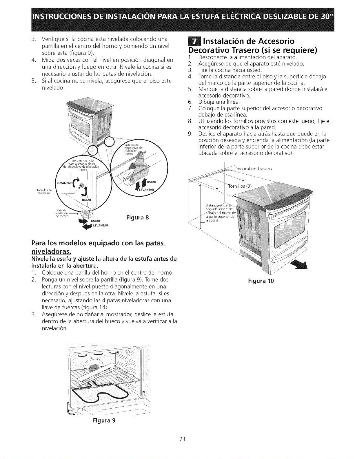
3. Verifiquesilacocinaest_qniveladacolocandouna
parrillaenelcentrodelhomoyponiendounnivel
sobreesta(figura9).
4. Midadosvecesconelnivelenposici6ndiagonalen
unadirecci6ny luegoenotra.Nivelelacocinasies
necesarioajustandolaspatasdenivelaci6n.
5. Sialcocinanosenivela,aseg0resequeelpisoeste
nivelado.
Tor niHos de
nivdaci6n
Pata de
nivdaci6n
de fr ente
Figura 8
Para los rnodelos equipado con ias patas
niveladoras.
Nivele la esufa y ajuste la altura de la estufa antes de
instalarla en la abertura.
1. Coloque una parilla del homo en el centro del homo.
2. Ponga un nivel sobre la parrilla (figura 9). Tome dos
lecturas con el nivel puesto diagonalmente en una
direcci6n y despu_s en la otra. Nivele la estufa, sies
necesario, ajustando las 4 patas niveladoras con una
Ilave de tuercas (figura 14).
3. Aseg0rese de no dahar al mostrador, deslice la estufa
dentro de la abertura del hueco y vuelva a verificar a la
nivelaciOn.
| Instalacion de Accesorio
Decorativo Trasero (si se requiere)
1. Desconecte la alimentaciOn del aparato.
2. Aseg0rese de que el aparato est_ nivelado.
3. Tire la cocina hacia usted.
4. Tome la distancia entre el piso y la superficie debajo
del marco de la parte superior de la cocina.
5. Marque la distancia sobre la pared donde instalar_qel
accesorio decorativo.
6. Dibuje una linea.
7. Coloque la parte superior del accesorio decorativo
debajo de esa linea.
8. Utilizando los tornillos provistos con este juego, fije el
accesorio decorativo a la pared.
9. Deslice el aparato hacia atr_ishasta que quede en la
posici6n deseada y encienda la alimentaci6n (la parte
inferior de la parte superior de la cocina debe estar
ubicada sobre el accesorio decorativo).
J
Decorativo trasero
_Tornillos (3)
Distanc_
pis_yfla superficie
-dgbajo del marco de
la parte superior de
la cocina.
Figura 10
Figura 9
21
Comprobacion del
Funcionamiento
Consulte el Manual del Usuario incluido con la estufa
para instrucciones de operaci6n y instrucciones para el
cuidado y limpieza de su estufa.
No toque los elemento. Pueden estar
bastante calientes para causar quemaduras.
Quite todo el embalaje de la unidad antes de
comprobarla.
1. Operation de los elementos de superfide
Encienda cada uno de los cuatro elementos de superficie
y controle que secalienten. Verifique el funcionamiento
de lasluces indicadoras de los elementos de superficie, si
equipadas.
2. Funcionamiento de los Elementos del Homo
El homo est,1equipado con un control electrOnico.
Cada funci6n ha sido probada en la f_ibrica antes del
transporte. Sin embargo, sugerimos que Ud. verifique el
funcionamiento de los controles del homo una vez m_is.
V_ase el Manual del Usuario para la operaci6n. Siga las
instrucciones par el Reloj Minutero, Cocer, Asar, ConvecciOn
(algunos modelos) y las funciones de limpieza.
Despues de Terminar la Instalad6n
Aseg0rese de que todos los controles est_n en la posiciOn
OFF(apagada).
Ubicacion del Numero de Modelo y de Serie
La placa con el n0mero de serie est,1ubicada en el
marco delantero del homo detr_is de la puerta del homo
(algunos modelos) o detr_is del caj6n (algunos modelos).
Cuando haga pedidos de repuestos o solicite informaci6n
con respecto a su estufa, est@siempre seguro de incluir
el nOmero de modelo y de serie y el nOmero o letra del
Iote de la placa de serie de su estufa.
Antes de Llamar al Servicio
Lea la secciOn Evite Llamadas de Servicio en su Manual
del Usuario. Esto le podr_i ahorrar tiempo y gasto. Esta
lista incluye ocurrencias comunes que no son el resultado
de defectos de materiales o fabricaci6n de este artefacto.
Lea la garantia y la informaci6n sobre el servicio en su
Manual del Usuario para obtener el n0mero de tel@fono
gratuito y la direcci6n del servicio. Por favor Ilame o
escriba si tiene preguntas acerca de su estufa o necesita
repuestos.
Cocer/Bake-Despu_s de poner el homo a 350°F (177°C)
para cocer, el elemento inferior debe ponerse rojo
Asar/BroiI-Cuando est,1puesto para BROIL,el elemento
superior se debe poner rojo.
Mmpieza/Clean-Cuando el homo est,1puesto para un
ciclo de auto-limpieza, el elemento superior se pondr_i
rojo durante el periodo de precalentamiento del ciclo.
Despu_s de alcanzar la temperatura de auto-limpieza, el
elemento inferior se pondr_i rojo.
ConvectiOn/Convection (algunos modelos)-Cuando el
homo se pone a CONV. BAKE/ROASTa 350% (177°C), los
dos elementos se enciendan y se apagan alternando en
un ciclo y el ventilador se pone en marcha. El ventilador
de convecci0n se parar_i cuando se abre la puerta del
homo durante el cocido o el asado por convecci0n.
Caj6n calentador (algunos modelos)-Ponga la perilla
de control a HI y verifique que se est,1calentando el caj6n.
22
Instrucdones de instalad6n de la
fijacion anti-inclinacion - Modelos con
una cubierta ceramico vidriado
Para los modelos equipado con un
sistema de dispositivo de nNelad6n.
Parareducir el riesgo de inclinaciOn de
la cocina, _sta debe ser asegurada hacia el piso con las
fijaciones de anti-inclinaci6n y los tornillos que vienen con
la cocina. Estoscomponentes se encuentran en el homo.
Si no instala lasfijaciones, corre el riesgo que su cocina
pueda inclinarse si pone demasiado peso en ella o si un
niho sube sobre _sta. Esto podria ocasionar graves heridas
causadas por liquidos calientes o por la propia cocina.
Siga estas instrucciones para instalar lasfijaciones de anti-
inclinaciOn.
Si la cocina es trasladada a otto lugar, las fijaciones de anti-
inclinaci6n deben tambi_n sertrasladados con la cocina.
Herramientas necesarias:
Llavede tuerca ajustable
Trinquete
Taladro el#ctrico con barrena de 1/8"(0,32 cm)
Aprietatuercas de 5/16" (0,8 cm)
Nivel
Abrazadera sujetada al suelo en la parte trasera de la
cocina para tener asida la parte posterior de la cocina. AI
fijarla al suelo, verificar que los tornillos no atraviesen la
instalaci6n el#ctrica o de fontaneria. Los tornillos provistos
sirven para madera o concreto.
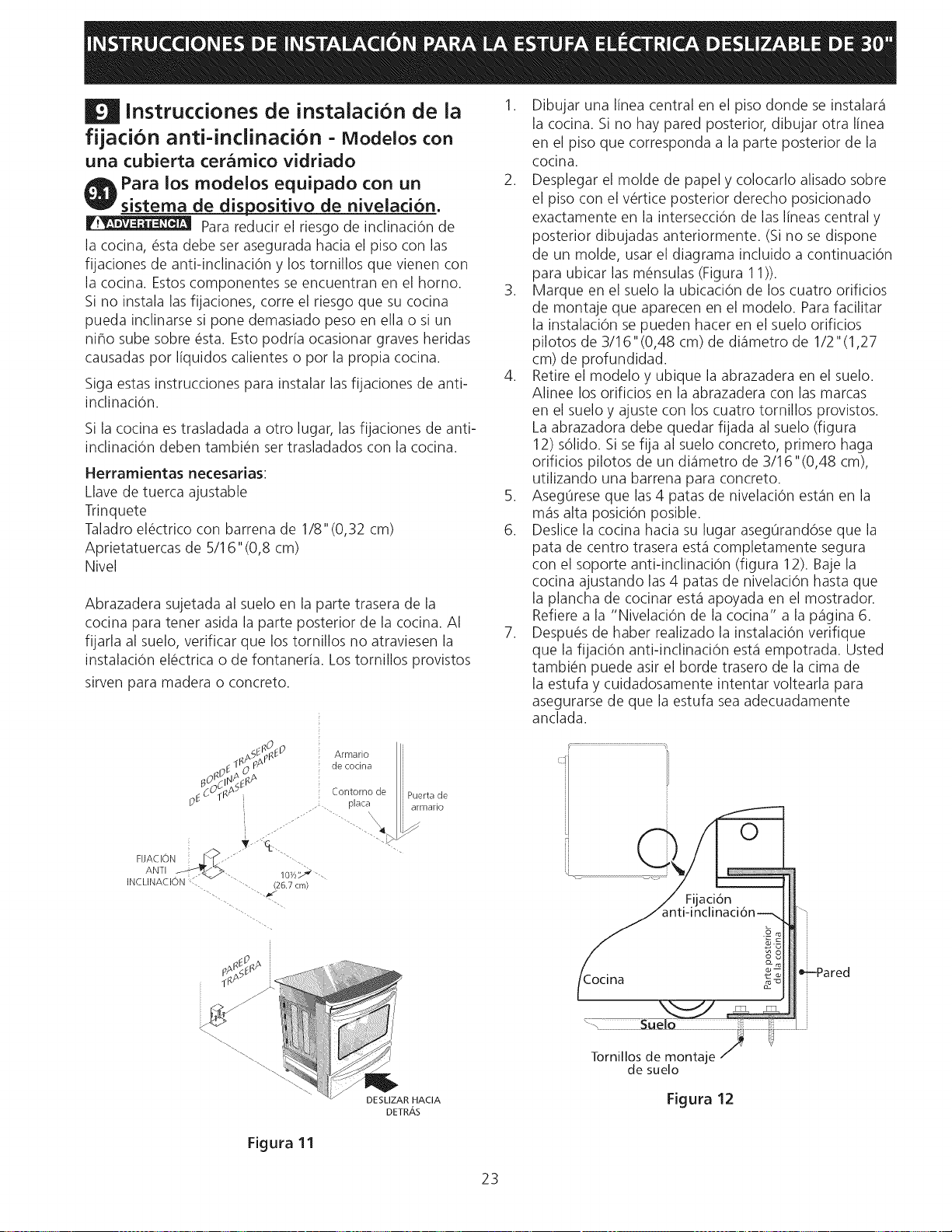
1. Dibujar una linea central en el piso donde se instalar_i
la cocina. Si no hay pared posterior, dibujar otra linea
en el piso que corresponda a la parte posterior de la
cocina.
2. Desplegar el molde de papel y colocarlo alisado sobre
el piso con el v#rtice posterior derecho posicionado
exactamente en la intersecci6n de las lineas central y
posterior dibujadas anteriormente. (Si no sedispone
de un molde, usar el diagrama incluido a continuaci6n
para ubicar las m#nsulas (Figura 11)).
3. Marque en el suelo la ubicaci6n de los cuatro orificios
de montaje que aparecen en el modelo. Parafacilitar
la instalaci6n se pueden hacer en el suelo orificios
pilotos de 3/16" (0,48 cm) de di_imetro de 1/2 "(1,27
cm) de profundidad.
4. Retire el modelo y ubique la abrazadera en el suelo.
Alinee los orificios en la abrazadera con las marcas
en el suelo y ajuste con los cuatro tornillos provistos.
La abrazadora debe quedar fijada al suelo (figura
12) s61ido.Si se fija al suelo concreto, primero haga
orificios pilotos de un di_imetro de 3/16"(0,48 cm),
utilizando una barrena para concreto.
5. Aseg0rese que las4 patas de nivelaci6n est_qnen la
m_qsalta posici6n posible.
6. Deslice la cocina hacia su lugar aseg0rand6se que la
pata de centro trasera est_qcompletamente segura
con el soporte anti-inclinaci6n (figura 12). Baje la
cocina ajustando las4 patas de nivelaci6n hasta que
la plancha de cocinar est_qapoyada en el mostrador.
Refiere a la "Nivelaci6n de la cocina" a la p_igina 6.
7. Despu#s de haber realizado la instalaci6n verifique
que la fijaci6n anti-inclinaci6n est_qempotrada. Usted
tambi#n puede asir el horde trasero de la cima de
la estufa y cuidadosamente intentar voltearla para
asegurarse de que la estufa seaadecuadamente
anclada.
_l Or
FIJACION SD
ANTI ,_>
INCLINACION
T-°C t
10y2_ '4
26.7 cm/
O
aclon
Figura 11
DESLIZAR HACIA
DETR,_,S
Tornillos de montaje
de suelo
Figura 12
23
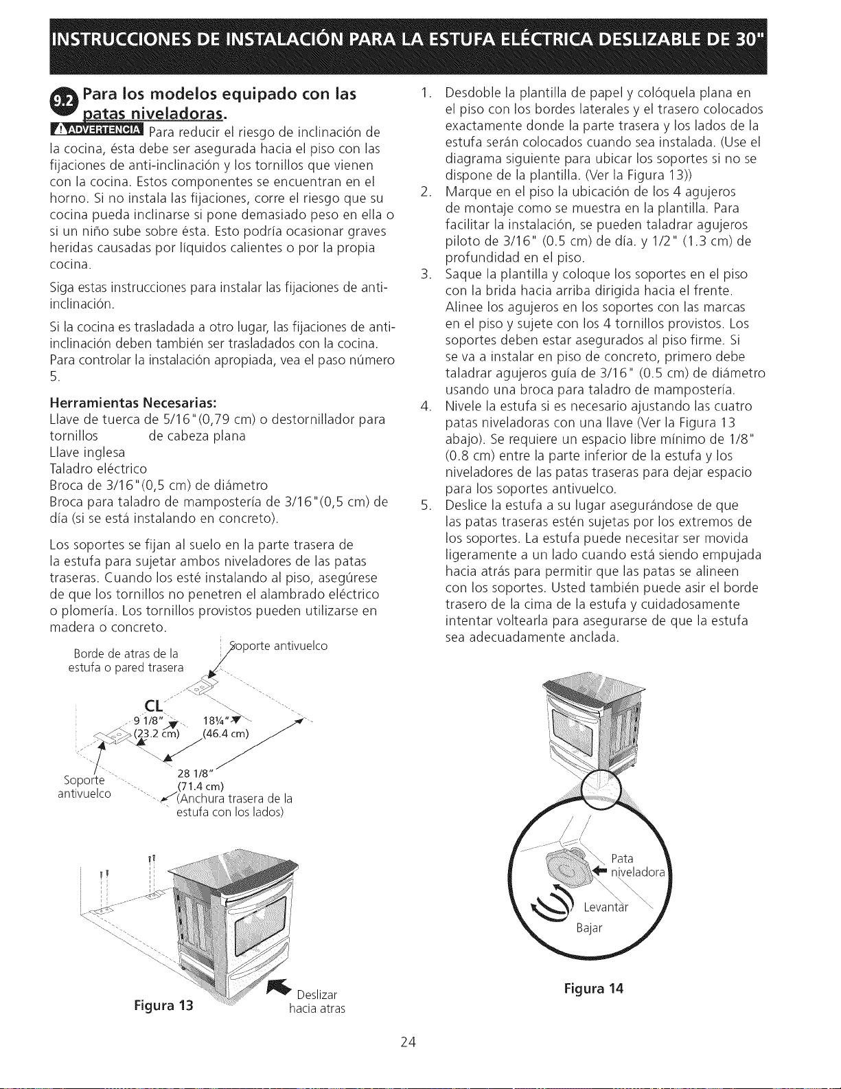
Para los modelos equipado con ias
_veladoras.
Para reducir el riesgo de inclinaciOn de
la cocina, _sta debe set asegurada hacia el piso con las
fijaciones de anti-inclinaci6n y los tornillos que vienen
con la cocina. Estos componentes se encuentran en el
homo. Si no instala las fijaciones, corre el riesgo que su
cocina pueda inclinarse si pone demasiado peso en ella o
si un niho sube sobre _sta. Esto podria ocasionar graves
heridas causadas pot liquidos calientes o pot la propia
cocina.
Siga estas instrucciones para instalar las fijaciones de anti-
inclinaciOn.
Si la cocina estrasladada a otto lugar, lasfijaciones de anti-
inclinaci6n deben tambi_n set trasladados con la cocina.
Para controlar la instalaciOn apropiada, vea el paso nOmero
5.
Herramientas Necesarias:
Llave de tuerca de 5/16"(0,79 cm) o destornillador para
tornillos de cabeza plana
Llave inglesa
Taladro el_ctrico
Broca de 3/16"(0,5 cm) de di_imetro
Broca para taladro de mamposteria de 3/16"(0,5 cm) de
dia (si se est_qinstalando en concreto).
Los soportes se fijan al suelo en la parte trasera de
la estufa para sujetar ambos niveladores de las patas
traseras. Cuando los est_ instalando al piso, asegOrese
de que los tornillos no penetren el alambrado el_ctrico
o plomeria. Los tornillos provistos pueden utilizarse en
madera o concreto.
Bordede atrasde la _oporte
antivuelco
estufao paredtrasera ,_i_'i"-
/
_<<_ ....--,
,_--_:_ (23.2 cm) (46.4 cm)
: "_ .... " ' 28 1/8"_
Soporte --, . (71.4cm)
antivuelco "--_S(Anchura traserade la
estufacon loslados)
_1_ Deslizar
Figura 13 hacia atras
1. Desdoble la plantilla de papel y col6quela plana en
el piso con los hordes laterales y el trasero colocados
exactamente donde la parte trasera y los lados de la
estufa seran colocados cuando sea instalada. (Use el
diagrama siguiente para ubicar los soportes si no se
dispone de la plantilla. (Vet la Figura 13))
2. Marque en el piso la ubicaci6n de los 4 agujeros
de montaje como se muestra en la plantilla. Para
facilitar la instalaci6n, se pueden taladrar agujeros
piloto de 3/16" (0.5 cm) de dia. y 1/2" (1.3 cm) de
profundidad en el piso.
3. Saque la plantilla y coloque los soportes en el piso
con la brida hacia arriba dirigida hacia el frente.
Alinee los agujeros en los soportes con las marcas
en el piso y sujete con los 4 tornillos provistos. Los
soportes deben estar asegurados al piso firme. Si
se va a instalar en piso de concreto, primero debe
taladrar agujeros guia de 3/1 6" (0.5 cm) de diametro
usando una broca para taladro de mamposteria.
4. Nivele la estufa si es necesario ajustando las cuatro
patas niveladoras con una Ilave (Vet la Figura 13
abajo). Se requiere un espacio libre minimo de 1/8"
(0.8 cm) entre la parte inferior de la estufa y los
niveladores de las patas traseras para dejar espacio
para los soportes antivuelco.
5. Deslice la estufa a su lugar asegurandose de que
las patas traseras est6n sujetas por los extremos de
los soportes. La estufa puede necesitar set movida
ligeramente a un lado cuando esta siendo empujada
hacia atr_is para permitir que las patas se alineen
con los soportes. Usted tambi6n puede asir el horde
trasero de la cima de la estufa y cuidadosamente
intentar voltearla para asegurarse de que la estufa
sea adecuadamente anclada.
Figura 14
24

