

2
FROM THE DESK OF OUR PRESIDENT
Dear new owner of a Bertazzoni appliance,
I want to thank you for choosing one of our beautiful products for your home.
My family started manufacturing kitchen appliances in Italy in 1882, building a
reputation for quality of engineering and passion for good food.
Today, our products stand out because of their unique blend of authentic Italian
design and superior appliance technology. It is our mission to make products that
function perfectly and bring joy to their owners.
By making beautiful products we respond to our customers’ flair for good design. By
making them versatile and easy-to-use, cooking with Bertazzoni becomes a real
pleasure.
This manual will help you learn to use and care for your Bertazzoni appliance in the
safest and most effective way, so that it can give you the highest satisfaction for
years to come.
Enjoy!
Paolo Bertazzoni
President
3

4

MANUAL VALIDITY
The following manual is valid for all the product codes mentioned below:
• REF24WCBPNV
• REF18WCBPLV
• REF18WCBPRV
5

6
CONTENTS
GENERAL INFORMATION . . . . . . . . . . . . . . . . . . . . . . . . . . . . . . . . . . . . . . . . . . . . . . . . . . . . . . . . . . . . . . . . . . . . . . . . . . 7
MANUAL INFORMATION . . . . . . . . . . . . . . . . . . . . . . . . . . . . . . . . . . . . . . . . . . . . . . . . . . . . . . . . . . . . . . . . . . . . . . . 7
SAFETY INFORMATION . . . . . . . . . . . . . . . . . . . . . . . . . . . . . . . . . . . . . . . . . . . . . . . . . . . . . . . . . . . . . . . . . . . . . . . . 8
CARING FOR THE ENVIRONMENT . . . . . . . . . . . . . . . . . . . . . . . . . . . . . . . . . . . . . . . . . . . . . . . . . . . . . . . . . . . . . 10
ENERGY SAVING . . . . . . . . . . . . . . . . . . . . . . . . . . . . . . . . . . . . . . . . . . . . . . . . . . . . . . . . . . . . . . . . . . . . . . . . . . . . 10
MOVING THE APPLIANCE . . . . . . . . . . . . . . . . . . . . . . . . . . . . . . . . . . . . . . . . . . . . . . . . . . . . . . . . . . . . . . . . . . . . . 10
SPECIFICATIONS . . . . . . . . . . . . . . . . . . . . . . . . . . . . . . . . . . . . . . . . . . . . . . . . . . . . . . . . . . . . . . . . . . . . . . . . . . . . . . . . 11
APPLIANCE DESCRIPTION . . . . . . . . . . . . . . . . . . . . . . . . . . . . . . . . . . . . . . . . . . . . . . . . . . . . . . . . . . . . . . . . . . . . 11
TECHNICAL SPECIFICATIONS . . . . . . . . . . . . . . . . . . . . . . . . . . . . . . . . . . . . . . . . . . . . . . . . . . . . . . . . . . . . . . . . . 11
ROOM TEMPERATURE . . . . . . . . . . . . . . . . . . . . . . . . . . . . . . . . . . . . . . . . . . . . . . . . . . . . . . . . . . . . . . . . . . . . . . . 11
INSTALLATION INSTRUCTIONS . . . . . . . . . . . . . . . . . . . . . . . . . . . . . . . . . . . . . . . . . . . . . . . . . . . . . . . . . . . . . . . . . . . . 12
PREPARING FOR INSTALLATION . . . . . . . . . . . . . . . . . . . . . . . . . . . . . . . . . . . . . . . . . . . . . . . . . . . . . . . . . . . . . . . 12
CABINET DIMENSIONS . . . . . . . . . . . . . . . . . . . . . . . . . . . . . . . . . . . . . . . . . . . . . . . . . . . . . . . . . . . . . . . . . . . . . . . 13
PRODUCT DIMENSIONS . . . . . . . . . . . . . . . . . . . . . . . . . . . . . . . . . . . . . . . . . . . . . . . . . . . . . . . . . . . . . . . . . . . . . . 15
CUSTOM DOOR PANEL . . . . . . . . . . . . . . . . . . . . . . . . . . . . . . . . . . . . . . . . . . . . . . . . . . . . . . . . . . . . . . . . . . . . . . . 16
ANTI TIP BRACKETS LOCATION . . . . . . . . . . . . . . . . . . . . . . . . . . . . . . . . . . . . . . . . . . . . . . . . . . . . . . . . . . . . . . . 17
ELECTRICAL REQUIREMENTS . . . . . . . . . . . . . . . . . . . . . . . . . . . . . . . . . . . . . . . . . . . . . . . . . . . . . . . . . . . . . . . . 18
VENTILATION . . . . . . . . . . . . . . . . . . . . . . . . . . . . . . . . . . . . . . . . . . . . . . . . . . . . . . . . . . . . . . . . . . . . . . . . . . . . . . . 19
TOOL LIST . . . . . . . . . . . . . . . . . . . . . . . . . . . . . . . . . . . . . . . . . . . . . . . . . . . . . . . . . . . . . . . . . . . . . . . . . . . . . . . . . . 20
UNPACKING . . . . . . . . . . . . . . . . . . . . . . . . . . . . . . . . . . . . . . . . . . . . . . . . . . . . . . . . . . . . . . . . . . . . . . . . . . . . . . . . . 20
REMOVING THE VENT HOLE ASSEMBLY . . . . . . . . . . . . . . . . . . . . . . . . . . . . . . . . . . . . . . . . . . . . . . . . . . . . . . . 21
REVERSING THE DOOR (IF APPLICABLE) . . . . . . . . . . . . . . . . . . . . . . . . . . . . . . . . . . . . . . . . . . . . . . . . . . . . . . . 22
INSTALLATION INSTRUCTION (DOOR ON DOOR HINGE) . . . . . . . . . . . . . . . . . . . . . . . . . . . . . . . . . . . . . . . . . . 27
MOUNTING THE ANTI-TIP BRACKETS . . . . . . . . . . . . . . . . . . . . . . . . . . . . . . . . . . . . . . . . . . . . . . . . . . . . . . . . . . 28
INSTALLATION IN THE CABINET . . . . . . . . . . . . . . . . . . . . . . . . . . . . . . . . . . . . . . . . . . . . . . . . . . . . . . . . . . . . . . . 31
SCREWING THE SIDE AND UPPER BRACKETS . . . . . . . . . . . . . . . . . . . . . . . . . . . . . . . . . . . . . . . . . . . . . . . . . . 33
ADJUSTING THE HEIGHT . . . . . . . . . . . . . . . . . . . . . . . . . . . . . . . . . . . . . . . . . . . . . . . . . . . . . . . . . . . . . . . . . . . . . 33
ADJUSTING THE REFRIGERATOR ACCORDING TO THE CABIN FLANGE . . . . . . . . . . . . . . . . . . . . . . . . . . . . 35
ATTACHING THE VENT HOLE ASSEMBLY . . . . . . . . . . . . . . . . . . . . . . . . . . . . . . . . . . . . . . . . . . . . . . . . . . . . . . . 36
ATTACHING THE DECORATIVE PARTS . . . . . . . . . . . . . . . . . . . . . . . . . . . . . . . . . . . . . . . . . . . . . . . . . . . . . . . . . 36
REMOVING THE PANEL-ADJUSTMENT MECHANISMS ON THE REFRIGERATOR . . . . . . . . . . . . . . . . . . . . . 37
PREPARING FURNITURE DOOR . . . . . . . . . . . . . . . . . . . . . . . . . . . . . . . . . . . . . . . . . . . . . . . . . . . . . . . . . . . . . . . 37
INSTALLING THE FURNITURE DOOR . . . . . . . . . . . . . . . . . . . . . . . . . . . . . . . . . . . . . . . . . . . . . . . . . . . . . . . . . . . 38
LIMITING PINS . . . . . . . . . . . . . . . . . . . . . . . . . . . . . . . . . . . . . . . . . . . . . . . . . . . . . . . . . . . . . . . . . . . . . . . . . . . . . . . 40
REMOVING THE SHELVES . . . . . . . . . . . . . . . . . . . . . . . . . . . . . . . . . . . . . . . . . . . . . . . . . . . . . . . . . . . . . . . . . . . . 41
ENSURING THE DOOR SEALS CORRECTLY . . . . . . . . . . . . . . . . . . . . . . . . . . . . . . . . . . . . . . . . . . . . . . . . . . . . . 41
USE . . . . . . . . . . . . . . . . . . . . . . . . . . . . . . . . . . . . . . . . . . . . . . . . . . . . . . . . . . . . . . . . . . . . . . . . . . . . . . . . . . . . . . . . . . . . 42
BEFORE FIRST USE . . . . . . . . . . . . . . . . . . . . . . . . . . . . . . . . . . . . . . . . . . . . . . . . . . . . . . . . . . . . . . . . . . . . . . . . . . 42
INTERNAL STORAGE . . . . . . . . . . . . . . . . . . . . . . . . . . . . . . . . . . . . . . . . . . . . . . . . . . . . . . . . . . . . . . . . . . . . . . . . . 43
CARBON FILTER . . . . . . . . . . . . . . . . . . . . . . . . . . . . . . . . . . . . . . . . . . . . . . . . . . . . . . . . . . . . . . . . . . . . . . . . . . . . . 47
RECOMMENDATIONS FOR STORING AND SERVING WINE . . . . . . . . . . . . . . . . . . . . . . . . . . . . . . . . . . . . . . . . 48
CONTROL PANEL . . . . . . . . . . . . . . . . . . . . . . . . . . . . . . . . . . . . . . . . . . . . . . . . . . . . . . . . . . . . . . . . . . . . . . . . . . . . 50
CARE AND MAINTENANCE . . . . . . . . . . . . . . . . . . . . . . . . . . . . . . . . . . . . . . . . . . . . . . . . . . . . . . . . . . . . . . . . . . . . . . . 53
LED LIGHT REPLACEMENT INSTRUCTIONS . . . . . . . . . . . . . . . . . . . . . . . . . . . . . . . . . . . . . . . . . . . . . . . . . . . . . 53
CLEANING THE INTERIOR SURFACES . . . . . . . . . . . . . . . . . . . . . . . . . . . . . . . . . . . . . . . . . . . . . . . . . . . . . . . . . . 53
CLEANING THE EXTERIOR SURFACES . . . . . . . . . . . . . . . . . . . . . . . . . . . . . . . . . . . . . . . . . . . . . . . . . . . . . . . . . 53
DEFROSTING . . . . . . . . . . . . . . . . . . . . . . . . . . . . . . . . . . . . . . . . . . . . . . . . . . . . . . . . . . . . . . . . . . . . . . . . . . . . . . . 53
NOISES AND MEANING . . . . . . . . . . . . . . . . . . . . . . . . . . . . . . . . . . . . . . . . . . . . . . . . . . . . . . . . . . . . . . . . . . . . . . . 53
POWER FAILURE . . . . . . . . . . . . . . . . . . . . . . . . . . . . . . . . . . . . . . . . . . . . . . . . . . . . . . . . . . . . . . . . . . . . . . . . . . . . 53
TROUBLESHOOTING . . . . . . . . . . . . . . . . . . . . . . . . . . . . . . . . . . . . . . . . . . . . . . . . . . . . . . . . . . . . . . . . . . . . . . . . . . . . 54
ERROR CODES . . . . . . . . . . . . . . . . . . . . . . . . . . . . . . . . . . . . . . . . . . . . . . . . . . . . . . . . . . . . . . . . . . . . . . . . . . . . . . . . . 55
CUSTOMER CARE . . . . . . . . . . . . . . . . . . . . . . . . . . . . . . . . . . . . . . . . . . . . . . . . . . . . . . . . . . . . . . . . . . . . . . . . . . . . . . . 56
GENERAL INFORMATION
MANUAL INFORMATION
These instructions are suitable for different types of
appliances, so they may contain descriptions of functions
which your appliance may not include or support.
The images and illustrations in this document refer to
various models and may differ slightly from the product
purchased.
The manufacturer does not accept any liability for personal
injury or damage to property arising from incorrect
installation or misuse of the appliance.
The manufacturer reserves the right to modify the various
models as required to comply with the technical regulations
in force.
In the event of complaints, please contact customer
service. Read the instructions provided in this manual
thoroughly before installing and/or using the appliance.
This will help you get to know your new appliance. Keep
this document at hand so that you can consult it at any
moment, and pass it on to any subsequent owners.
Read the safety messages provided in the introduction to
this manual and give due consideration to the safety notes,
such as: “Attention”, “Warning” and “Danger” which appear
in the text.
DANGER
This symbol indicates a situation that is a
danger to you and others. Read it carefully
and make sure that you have perfectly
understood the causes of potential
dangerous or fatal accidents.
WARNING
This symbol indicates safety information.
Read it carefully and make sure that you
have perfectly understood the causes of
potentially dangerous accidents.
CAUTION
This symbol indicates a procedure which
could put the appliance’s structure or
components at risk. Take particular care
over these procedures.
NOTE
This symbol highlights methods or
procedures for correct use of the appliance.
The Model, Sales Code and Serial Number are printed on
the nameplate. Refer to the Specifications section of this
manual for nameplate location.
NOTE
You are advised to make a note of the
appliance’s data and serial numbers so
they are immediately available if required.
NOTE
State the information provided on the
nameplate to improve the efficiency of the
after-sales and parts services. For warranty
purposes, you will also need the date of
installation and name of your authorized
Bertazzoni dealer.
WARNING
When using your appliance, follow basic
precautions. Read all instructions before
using the appliance. Save these
instructions and pass them on to any future
user.
7

GENERAL INFORMATION
SAFETY INFORMATION
This appliance is intended to be used in residential and
other similar applications, such as:
• Staff kitchen areas in shops, offices and other working
environments;
• In farm houses and by guests at hotels, motels and other
residential type environments;
• Bed and breakfast type environments;
• Catering and similar non-retail applications.
It must not be used in any way other than that which it is
intended. It must be used only for storing wine.
The manufacturer shall not be held liable for any damages
resulting from improper use or transport.
Original spare parts will be available for 10 years following
the product's purchase date.
WARNING
Prop. 65 Warning for California Residents:
This product may contain chemicals known
to the State of California to cause cancer,
birth defects, or other reproductive harm.
AVOIDING PLACING CHILDREN AND VULNERABLE
PEOPLE AT RISK
This appliance is not intended for use by individuals
(including children) with reduced physical or sensory
capabilities or lack of experience and knowledge unless
they are supervised or have been given instruction
concerning the use of the appliance by a person
responsible for their safety.
Children should be supervised to ensure that they do not
play with the appliance.
Cleaning and care should not be performed by children
unless they are supervised by an adult.
Keep the appliance and its cord out of reach of children
who are less than 8 years old.
RISK OF ELECTRIC SHOCK
• Make sure the appliance is unplugged during
installation, maintenance, cleaning, and repairs.
• When installing the appliance, ensure that the mains
cable is not trapped or damaged.
• If the power cord of this appliance is damaged, it must
be replaced by the manufacturer, customer service or a
similarly qualified person. Improper installations and
repairs may put the user at considerable risk.
• Plug the appliance into a grounded socket that is
protected by a fuse and that corresponds to the value on
the product's nameplate. The appliance should not be
plugged into a GFCI protected outlet.
Have a qualified electrician ground the appliance. Our
company cannot be held responsible for damages
resulting from a failure to use the appliance with a
grounded socket pursuant to local regulations.
• Do not use an adapter. Do not use an extension cord.
• Do not plug in the refrigerator if the wall socket is loose.
Do not pull on the cable to unplug the appliance.
• Unplug the appliance if you encounter a malfunction
during use. If the unit malfunctions, it must not be used
until it has been repaired by an Authorized Service
Provider. The manufacturer cannot be held responsible
for damages arising from procedures performed by
unauthorized persons.
• Never wash the appliance by pouring, daubing, or
spraying water onto it. Never touch the plug with wet
hands.
• Never use steam or steam cleaners to clean or defrost
the refrigerator. Steam can cause a short circuit or
electric shock if it comes into contact with your
refrigerator's electrical components.
• Never connect your refrigerator to an energy saving
device. Such systems are harmful to your appliance.
RISK OF EXPLOSION
• Do not use electrical appliances of any kind inside of the
food storage compartments.
• Do not use mechanical devices or other means to
accelerate the defrosting process; use only those
recommended by the manufacturer.
• Do not store explosive substances, such as aerosol
cans with a flammable propellant, inside this appliance.
• Bottles containing beverages with a high alcohol content
must be tightly closed and stored vertically.
8
GENERAL INFORMATION
RISK OF INJURY
• Do not put carbonated beverages or liquids in tins or
glass containers in the freezer compartment. They may
burst.
• Never use refrigerator components such as the door or
drawers as means of support or as steps. This may
cause the appliance to tip over or damage it.
• Do not sit on the appliance and do not place heavy
objects on top of the appliance.
• Do not sit or lean on the door or on any open drawers.
Do not put pressure on the door or use it to move the
appliance.
• Do not overload the refrigerator. Objects in the
refrigerator may fall when the door is opened, causing
injury or property damage.
• Do not place your hands or any other body part in the
moving parts of the refrigerator (i. e., automatic ice
maker).
RISK OF SUFFOCATION
• Packaging materials can be hazardous to children. Do
not allow children to play with plastic bags, plastic film,
or polystyrene.
• If there is a lock on the door of the appliance, the key
should be kept out of reach of children.
RISK OF FOOD POISONING
• Store raw meat and fish in the refrigerator in appropriate
containers so that it does not come into contact with or
drip onto other foods.
• Avoid leaving the door open for long periods of time, as
this can cause the temperature inside the appliance
compartments to rise significantly.
• Regularly clean surfaces that may come in contact with
food and accessible drainage systems.
• If the refrigerator is to be left unused for an extended
period of time, turn it off, defrost, clean, dry, and leave
the door open to prevent mold from growing inside the
appliance.
FIRE HAZARD / ISOBUTANE WARNING
The refrigerant circuit of the appliance contains
isobutane (R600a), a natural gas with a high
level of environmental friendliness, but which is
nevertheless flammable.
During transport and installation of the
appliance, take care not to damage any of the
components of the refrigerant circuit.
This appliance is CFC and HFC free.
If the refrigerant circuit should become damaged:
• avoid naked flames and sources of ignition.
• thoroughly ventilate the room in which the appliance is
located.
NOTE
If the appliance is damaged or if you see a
gas leak, please keep away from the gas. It
may cause ice burn if it comes into contact
with the skin.
NOTE
The type of gas used in the product is listed
on the rating label, which is located on the
left interior wall of the refrigerator.
CAUTION
• Do not damage areas where refrigerant
is circulating with drilling or cutting tools.
If the gas ducts in the evaporator, the
tubing extensions or the surface
coatings are punctured, the refrigerant
could blow out, causing skin irritation
and eye injuries. Do not use pointed or
sharp-edged implements to remove frost
or layers of ice. You could damage the
refrigerant tubes. Leaking refrigerant
may cause eye injuries or ignite.
• Never attempt to extinguish a flame/fire
with water: turn off the appliance and
cover the flame with a fireproof blanket.
• Do not cover or allow any object to block
the ventilation openings in your
refrigerator.
9
GENERAL INFORMATION
CARING FOR THE ENVIRONMENT
Pay special attention to correct disposal procedures for all
the packaging materials. Before disposal:
• Disconnect the mains power supply.
• Unplug the appliance and cut the power cord.
• Avoid damaging the refrigeration circuit during disposal.
WARNING
Please ensure that old and worn-out
appliances are rendered unusable before
disposal by removing the plug, cutting the
power cord and removing or destroying the
clips or snap bolts. This will prevent
children from locking themselves in the
appliance during play (risk of suocation) or
endangering their lives in any other way.
To protect the environment, it is essential to dispose of your
appliance packaging correctly. This includes both your old
appliance and your new unit once it has reached the end of
its service life.
WARNING
Fire or Explosion Hazard
Before discarding your old refrigerator or
freezer, please remove the doors. Keep the
shelves in place to prevent children from
easily climbing inside.
CAUTION
Fire or Explosion Hazard
Dispose of the refrigerator according to
applicable federal and local regulations, as
it contains flammable refrigerant.
NOTE
Do not dispose of this appliance with
regular household waste.
Take care not to damage the coolant circuit, especially the
heat exchanger located at the back or bottom of the unit.
The symbol on the product or its packaging indicates that
this appliance should not be treated as normal household
waste but should be taken to a designated recycling
collection point for electrical and electronic goods. By
disposing of this product correctly, you help protect the
environment. Improper disposal can pose risks to health
and the environment.
For more information about recycling, please contact your
local waste collection department or town hall.
ENERGY SAVING
For optimal energy saving, we recommend the following:
• Install the appliance away from heat sources, out of
direct sunlight and in a well-ventilated room.
• Do not overfill the compartments, as this prevents air
from circulating properly.
• In the event of an electrical power failure, it is advisable
to keep the refrigerator door closed.
• Open the appliance doors as infrequently and for the
briefest amounts of time possible.
• Ensure that the unit is adequately ventilated. Never
cover air vents.
• Never cover shelves with aluminum foil or any other
shelf material which may prevent air circulation.
• Should the appliance be left empty for long periods of
time, it is advisable to unplug it and, after thorough
cleaning, to leave the door ajar to allow air to circulate
inside the cabinet in order to prevent the formation of
condensation, mould or odours.
MOVING THE APPLIANCE
Should you need to relocate your appliance, take the
following precautions:
• Remove all items from the unit.
• Securely tape down all loose items (e.g. shelves) inside
the appliance.
• Turn the adjustable feet at the base clockwise until they
are fully raised to avoid damaging them.
• Tape the door shut.
• Ensure the appliance remains in an upright position
during transport.
• Protect the outer glass door with a blanket or similar
during transport.
10
SPECIFICATIONS
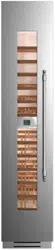
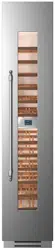
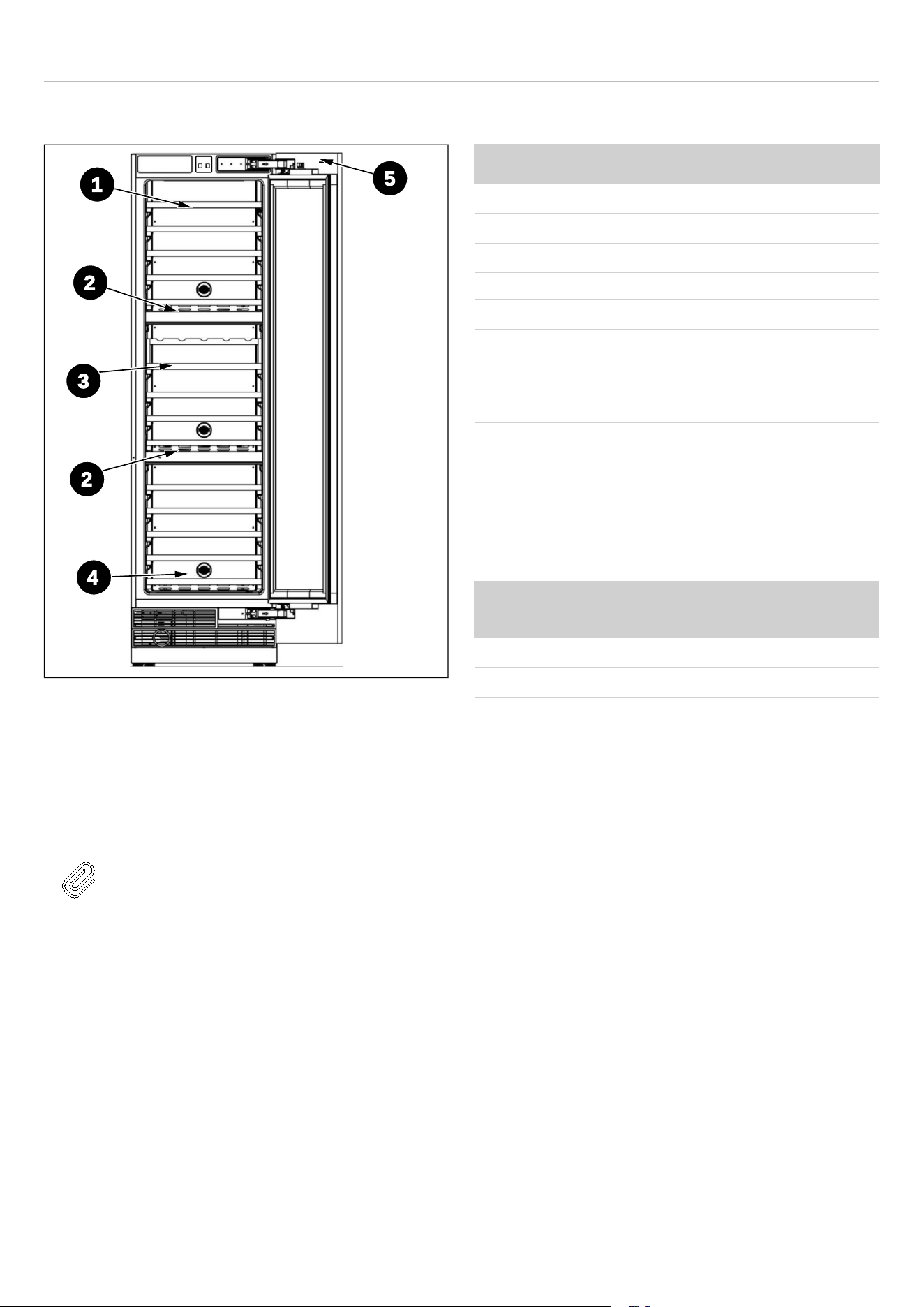
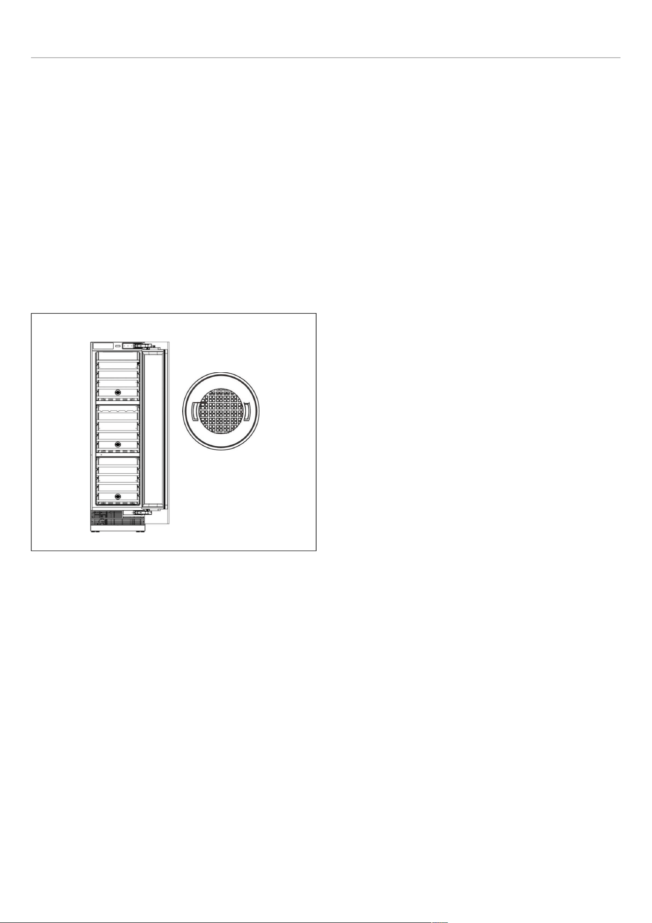
APPLIANCE DESCRIPTION
Fig. 1
1) Wine Shelf A
2) Control Panel &
Compartment Wall
3) Wine Shelf B
4) Carbon Filter
5) Electromagnetic Switch
NOTE
The figures in this user manual are
schematic and may not match the product
exactly. If your product does not have the
parts described, the information applies to
other models.
TECHNICAL SPECIFICATIONS
ELEMENT
DESCRIPTION
Plug type NEMA 5-15P
Voltage 115 V
Frequency 60 Hz
Fuse 10 A
Amperage 1.5 A
Capacity 68 Bordeaux bottles for 45
cm (18″) wine column
100 Bordeaux bottles for
24″ (60 cm) wine column
Refrigerant, volume and further technical specifications can
be found on the rating plate.
ROOM TEMPERATURE
The permitted room temperature depends on the climate
class:
CLIMATE CLASS PERMITTED ROOM
TEMPERATURE
SN (Sub Normal) + 50 ℉ to + 87 ℉
N (Normal) + 61 ℉ to + 87 ℉
ST (Sub Tropical) + 61 ℉ to + 100 ℉
T (Tropical) + 61 ℉ to + 109 ℉
2
5
3
1
4
2
11

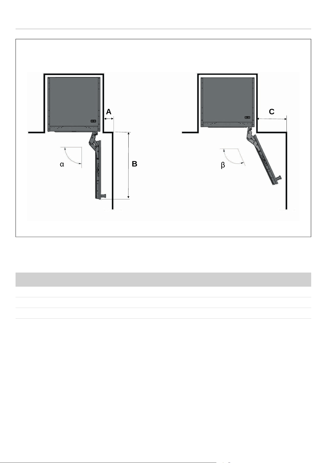
INSTALLATION INSTRUCTIONS
PREPARING FOR INSTALLATION
This appliance must not be installed close to heat
sources, e. g. heating elements or cookers, or in a
damp location.
Seek the help of one or two other individuals when
installing this appliance. This appliance may have
sharp edges. Wear PPE appropriate to the task and the
environment.
• Use the height-adjustable feet at the front of the
appliance to ensure that the appliance is level.
• The cooling system on the back of the appliance must
not touch the rear wall. The larger the gap, the better.
• The appliance must be installed with adequate
ventilation. Ensure that there is clearance above the
appliance to allow air to escape and that there is space
between the rear of the appliance and the wall.
Plug the appliance into an exclusive, easily accessible
electrical socket.
Any questions concerning power and/or electrical
connection should be directed towards a qualified
electrician or an authorized products service center.
12

INSTALLATION INSTRUCTIONS
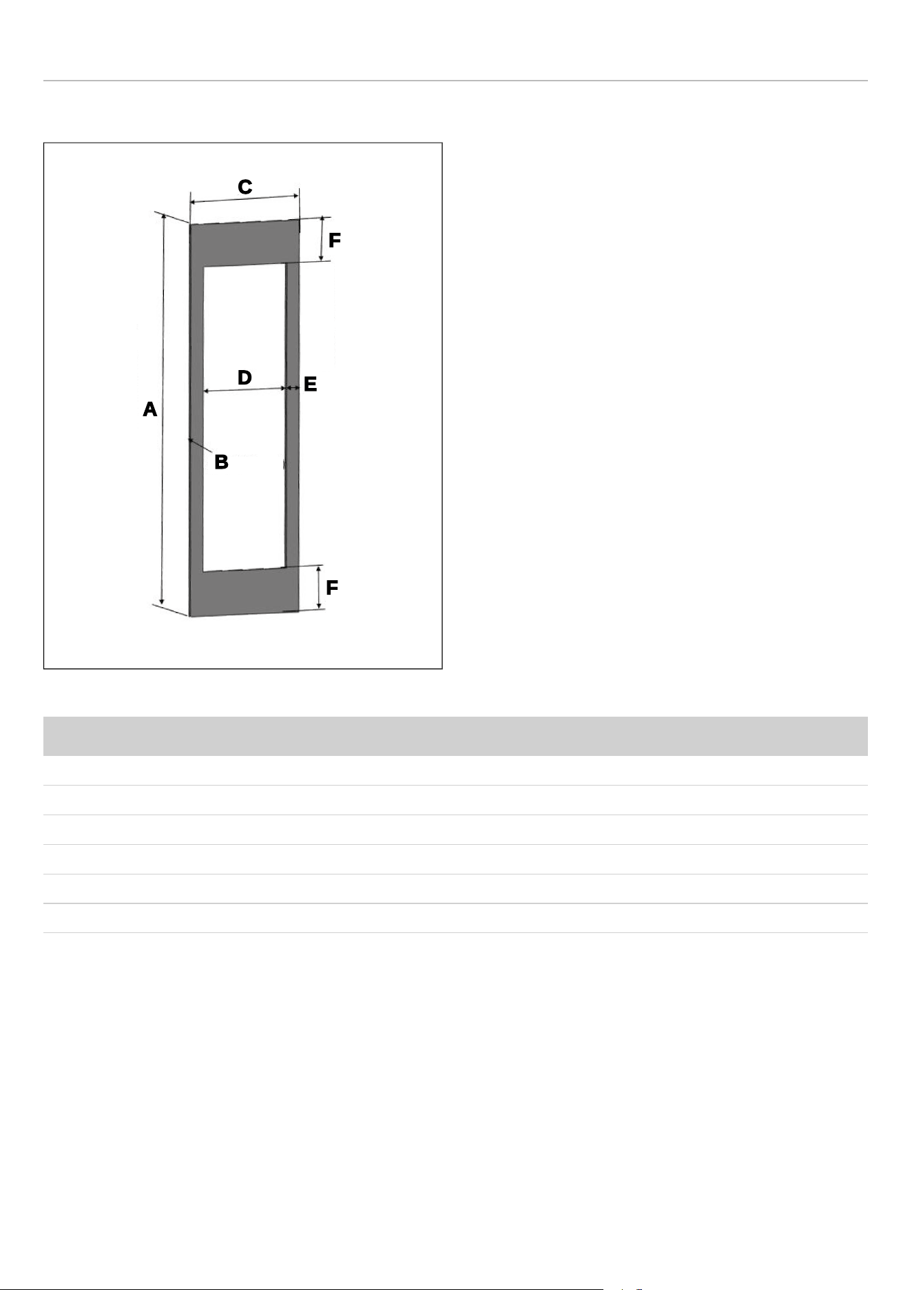
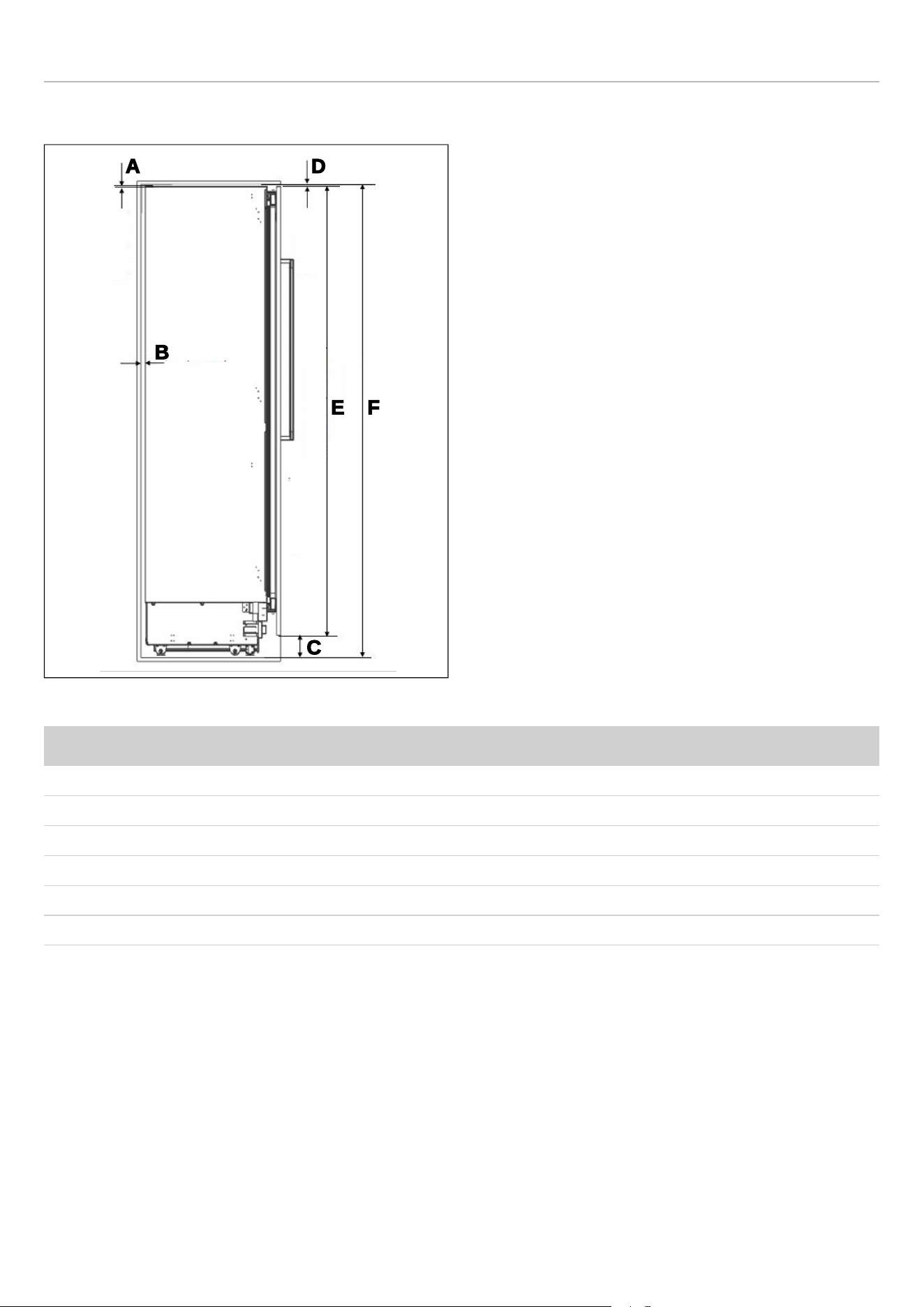
CABINET DIMENSIONS
Fig. 2
CATEGORY REF18WCBPRV / REF18WCBPLV REF24WCBPNV
A
18″ (457 mm) 24″ (609 mm)
B
25″ (635 mm) 25″ (635 mm)
C
standard 84″ ( 2134 mm)
minimum 83 3/4″ (2127 mm)
maximum 85 5/16″ (2167 mm)
standard 84″ ( 2134 mm)
minimum 83 3/4″ (2127 mm)
maximum 85 5/16″ (2167 mm)
D
1/8″ (3 mm) 1/8″ (3 mm)
E
1/8″ (3 mm) 1/8″ (3 mm)
F
standard 4″ (101 mm)
minimum 3 3/4″ (95 mm)
maximum 5 5/16″ (135 mm)
standard 4″ (101 mm)
minimum 3 3/4″ (95 mm)
maximum 5 5/16″ (135 mm)
D
E
F
A
B
C
13

INSTALLATION INSTRUCTIONS
CUSTOM DOOR PANEL
Fig. 5
CATEGORY REF18WCBPRV / REF18WCBPLV REF24WCBPNV
A
79 15/16″ (2030 mm) 79 15/16″ (2030 mm)
B
3/4″ - 1 1/2″ (19 - 38 mm ) thickness 3/4″ - 1 1/2″ (19 - 38 mm ) thickness
C
17 3/4″ (451 mm) 23 3/4″ (603 mm)
D
12 1/4″ (311 mm) 18 1/4″ (463 mm)
E
2 3/4″ (70 mm) 2 3/4″ (70 mm)
F
9 1/16″ (230 mm) 9 1/16″ (230 mm)
Max weight of custom door panel: 66 lbs (30 kg).
A
B
C
D
E
F
F
16
INSTALLATION INSTRUCTIONS
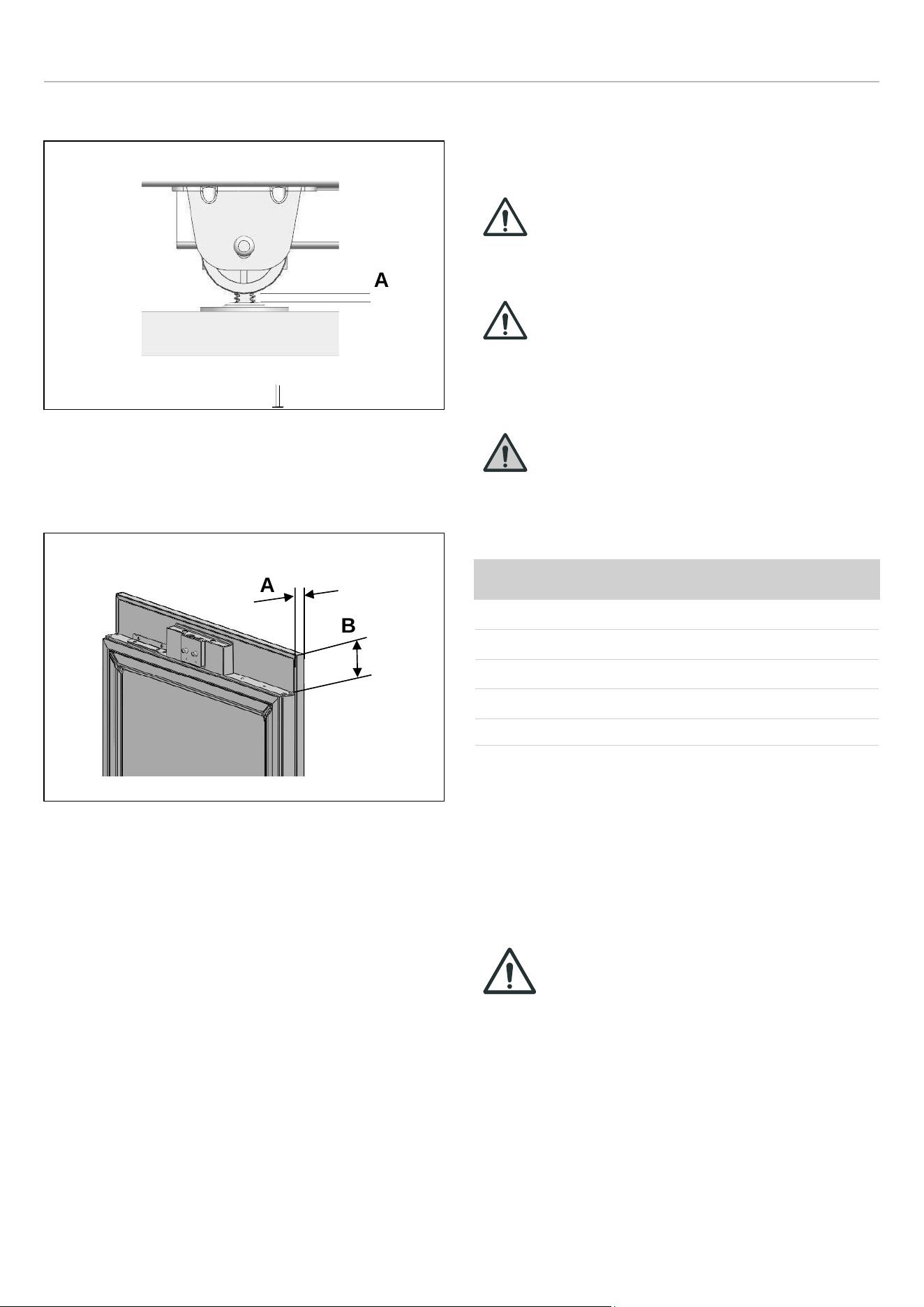
MINIMUM HEIGHT ADJUSTMENT FOR LEVELING
Fig. 7
A. 5/16″(8 mm)
ASSEMBLY DIMENSION BETWEEN WOOD PANEL AND
FRIDGE DOOR
Fig. 8
A. 3/4″ (19 mm)
B. 3 3/8″ (82 mm)
ELECTRICAL REQUIREMENTS
The appliance must be installed to all electrical connections
in accordance with state and local codes.
CAUTION
Do not use extension cords or two-prong
adapters and do not remove the ground
terminal of the grounding cable.
CAUTION
A qualified electrician must ensure that the
poles of the socket are connected correctly.
Verify that the grounding of the socket is
correct.
WARNING
Do not connect the appliance to electronic
energy saver plugs.
The socket must comply with the following data:
ELECTRICAL REQUIREMENTS
Plug type NEMA 5-15P
Outlet
3-prong
Voltage 115 V
Frequency 60 Hz
Fuse 10 A
The appliance must be plugged into its own individual
electrical outlet with a voltage rating that matches the rating
label on the appliance. This provides the best performance
and also prevent overloading wiring circuits that could
cause a fire hazard from overheating.
IMPORTANT
Do not use extension cords and/or multiple
adapters for the power supply connection.
If the electrical wiring or the electric power supply of the
house requires alteration, the necessary procedures must
be performed by a qualified electrician.
Please heed the following rules:
• The electrical outlet or panel must be easily accessible
in case of an emergency; it must not be hidden behind
the product.
A
A
B
18
INSTALLATION INSTRUCTIONS
• Neither the plug nor the cable may touch the back
surface of the appliance. Otherwise, it may be damaged
by the appliance's vibrations.
• To prevent accidental injury, the cord should be secured
behind the appliance and not left exposed or dangling.
• Do not connect other equipment plugs behind this
appliance. If the humidity level is high where the
appliance is being used, its exterior surfaces may
become corroded. To prevent corrosion, keep the
installation room dry and well-cleaned.
To prevent the risk of electric shock:
• Connect the plug to a grounded outlet.
• Do not remove plug's grounding prong.
• Do not use adapters.
• Do not use extension cords unless the cord has been
checked and tested by a qualified technician or service
person. The extension cord must be a UL/CUL Listed, 3-
wire grounding extension cord that has a grounding plug
and outlet and that the electrical rating of the cord is 115
volts and at least 10 amperes.
• Never unplug the appliance by pulling the power cord.
CAUTION
Do not connect the grounding cable to the
gas line. Please have the grounding
checked by a qualified electrician if you are
not sure about the grounding of the
appliance. Do not install a fuse on the
neutral line or on the grounding circuit.
CAUTION
Failure to follow these instructions may
result in fire, electric shock or death.
Connecting the appliance's grounding
conductor in the wrong place may lead to
electric shock. Please have the grounding
checked by a qualified electrician or service
technician if you have any doubt about the
proper grounding of the appliance.
Installation, repairs and other procedures
performed by unqualified persons may give
rise to hazards. Before installing the
appliance, make sure that the voltage, load
and circuit current parameters on the data
plate are in compliance with the power
supply in your house.
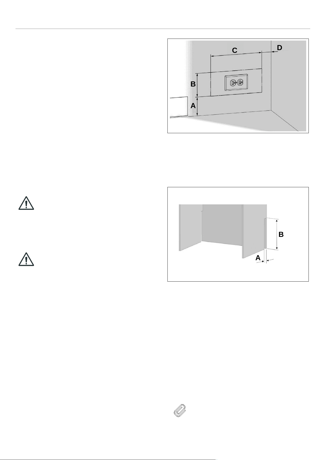
Fig. 9
• A 4″ (102 mm)
• B 5″ (127 mm)
• C 11″ (280 mm)
• D 2″ (50.8 mm)
Fig. 10
• A 2″ (50.8 mm)
• B 8″ (203.2 mm)
VENTILATION
The heat removed from the cooling compartment needs to
be dissipated into the air around the appliance. Incorrect
ventilation can lead to premature compressor failure,
excessive power consumption and total system failure, and
it may invalidate the warranty provided with the appliance.
There is a air ventilation grille at the base of the appliance.
The clearance at the rear of the appliance is clearly shown.
NOTE
The air vent at the front of the appliance
must never be covered or blocked in any
way.
A
B
C
D
A
B
19
INSTALLATION INSTRUCTIONS
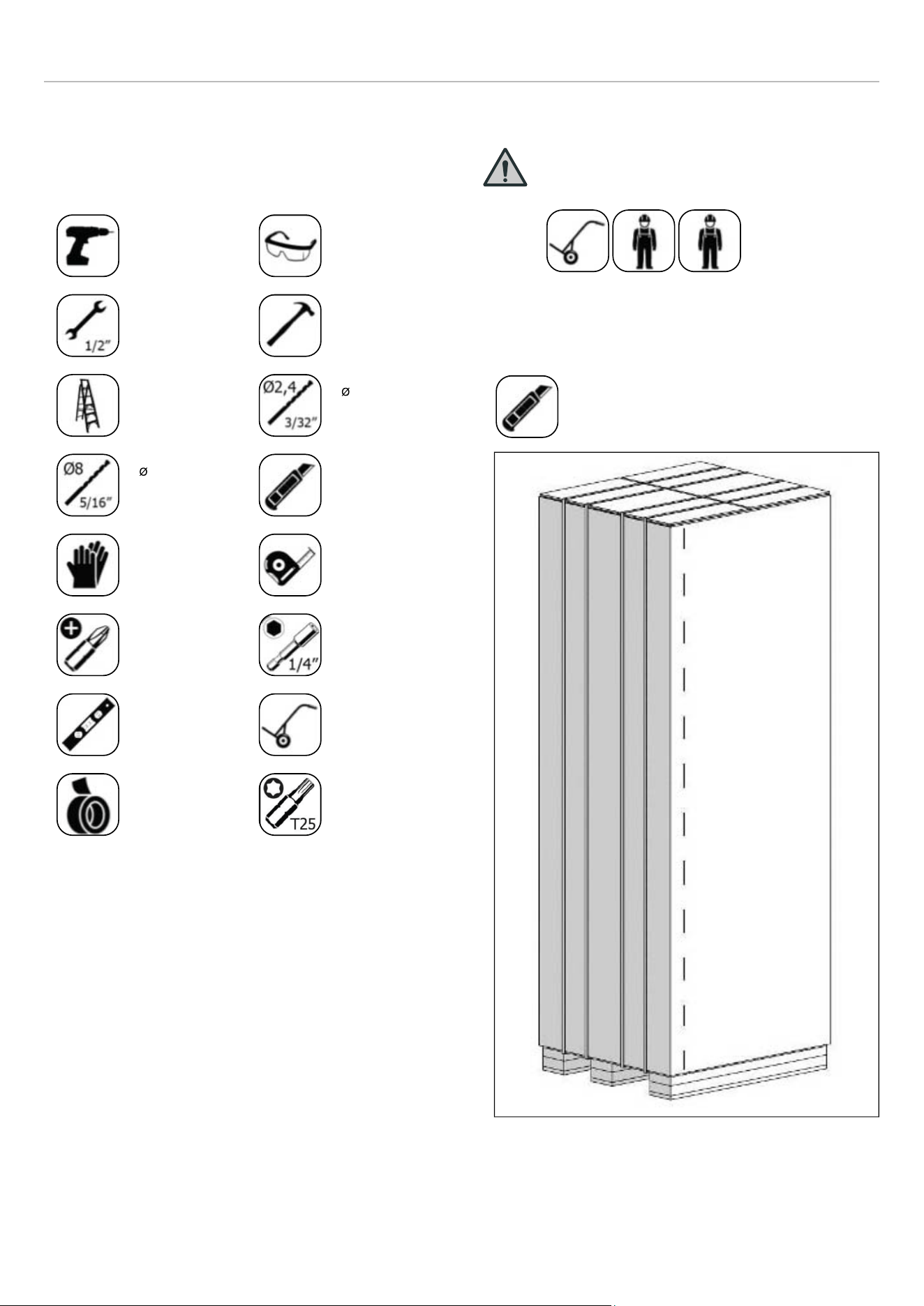
TOOL LIST
The tools to be used when installing the product are as
follows:
Cordless drill
Safety
goggles
12.7 mm (1/
2″) spanner
Hammer
Ladder
2.4 mm drill
bit
8.0 mm drill
bit
Box cutter
Safety gloves Tape measure
Phillips-head
bit
6.4 mm (1/4″)
hex bit
Bubble level
Appliance
trolley
Tape
T25 Torx Bits
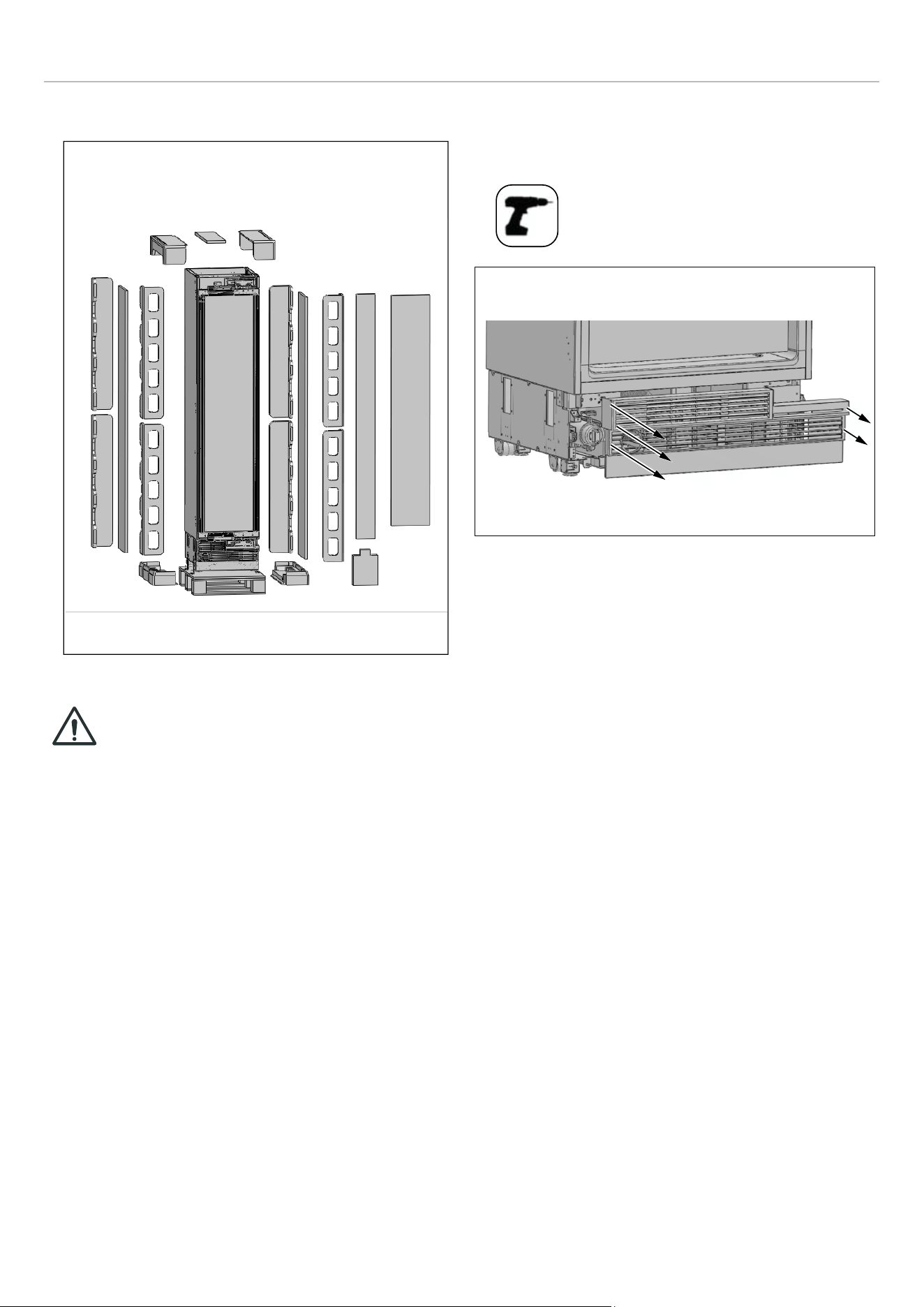
UNPACKING
WARNING
At least two people must carry the
refrigerator.
• Use a box cutter to remove the tape.
• Cut the cardboard packaging along the dotted lines
using a box cutter and remove it.
Fig. 11
20
INSTALLATION INSTRUCTIONS
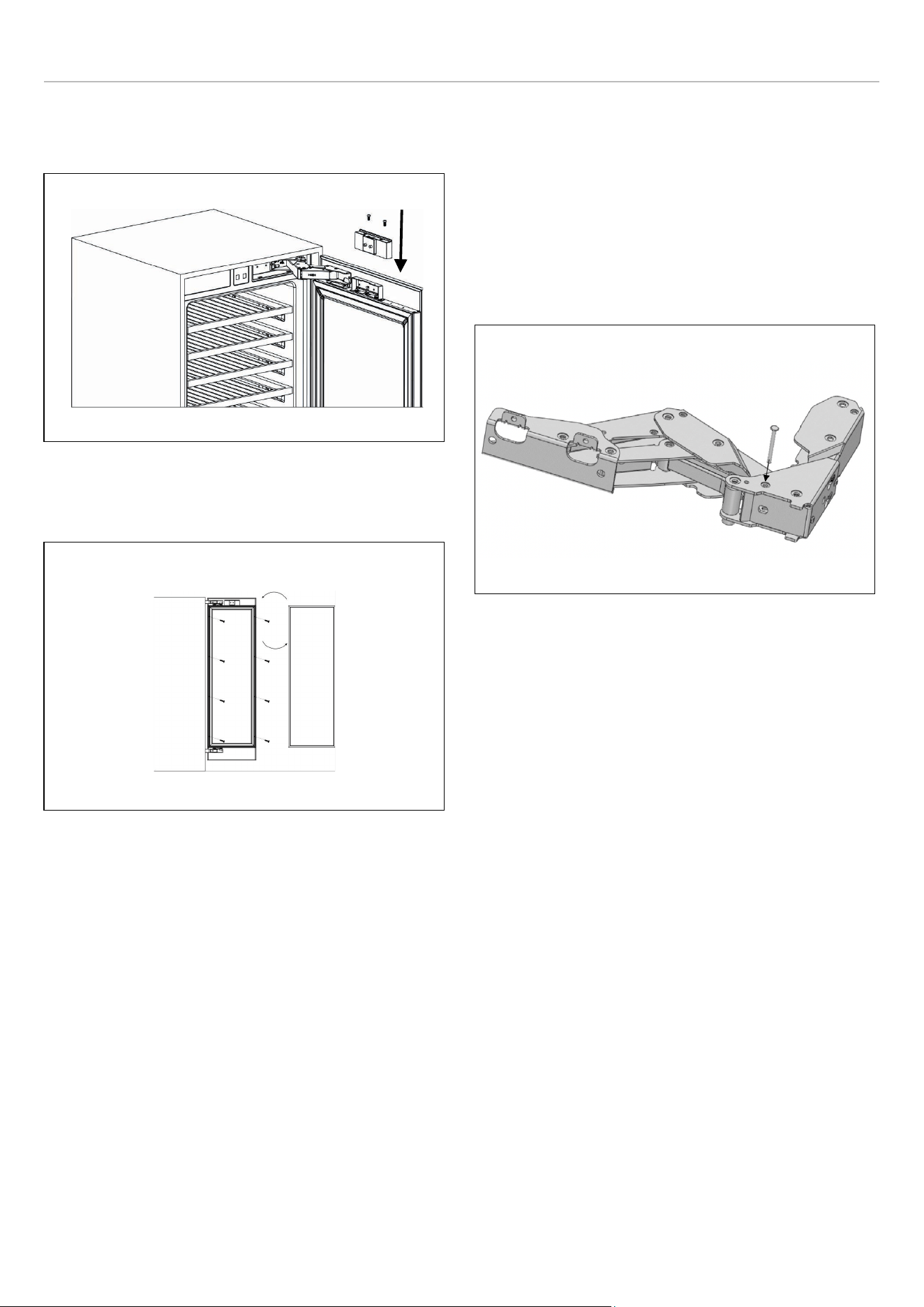
REVERSING THE DOOR (IF APPLICABLE)
We recommend you seek the help of another individual
to support the door while you perform this operation.
Depending on the installation position, the opening of the
wine cabinet can be switched. If necessary, do so before
placing the wine cooler into the cabinet.
• Remove the hinge connection screws from the hinge
brackets.
CAUTION
The door will be released when these
screws are removed. You must take
measures to prevent the door from
falling. You can tape the cabinet door to
the inner door or ask a second person to
help.
Fig. 14
• Take out door and lay it down on a table.
• Remove the hinge brackets on the fridge door.
• Take out the new hinge brackets from accessories bag
and screw them on the reverse side.
Fig. 15
22


INSTALLATION INSTRUCTIONS
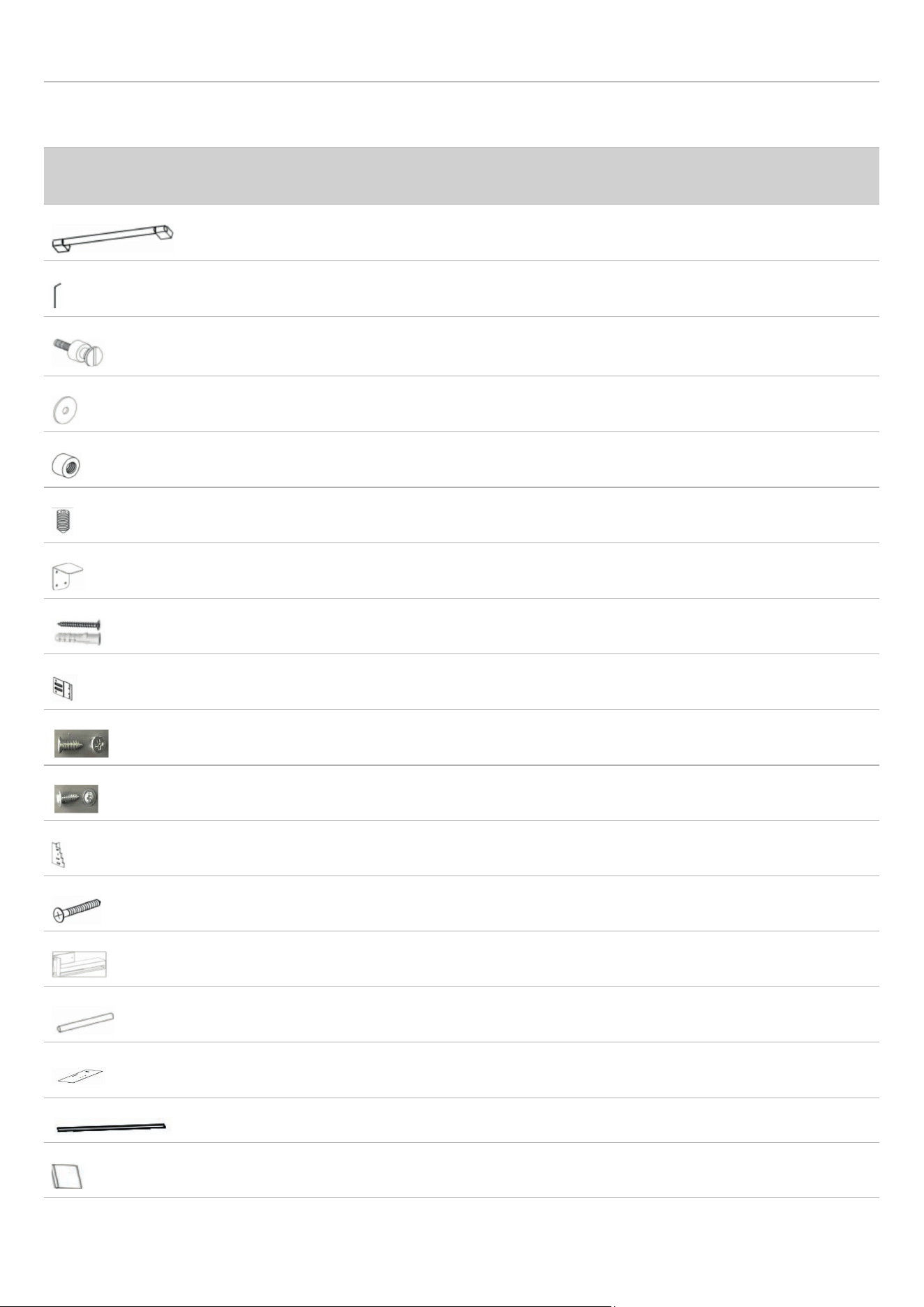
INSTALLATION INSTRUCTION (DOOR ON DOOR HINGE)
DESCRIPTION
REF18WCBPRV /
REF18WCBPLV
REF24WCBPNV
Door handle (if applicable)
1 1
Allen/hex key (if applicable)
1 1
Handle mounting fastener
(if applicable)
2 2
Gasket (if applicable)
2 2
Stop nut,M5 (if applicable)
2 2
set screw,M5*10 (if applicable)
2 2
Anti-tip bracket
2 2
Anti tip bracket screws and dowels
8 8
Bracket furniture
8 8
Counter sunk head screw,ST4x14
20 20
Truss washer head,ST4*12
16 16
Position adjustment part
1 1
Countersunk head screws for fixing wooden
doors ST4x35
8 8
Air vent hinge part(if applicable)
\ 1
90°limit pin
2 2
Furniture door preparation template
1 1
decorative parts
1+2+2 1+2+2
User manual
1 1
27
INSTALLATION INSTRUCTIONS
NOTE
The appliance must be plugged in before installation.
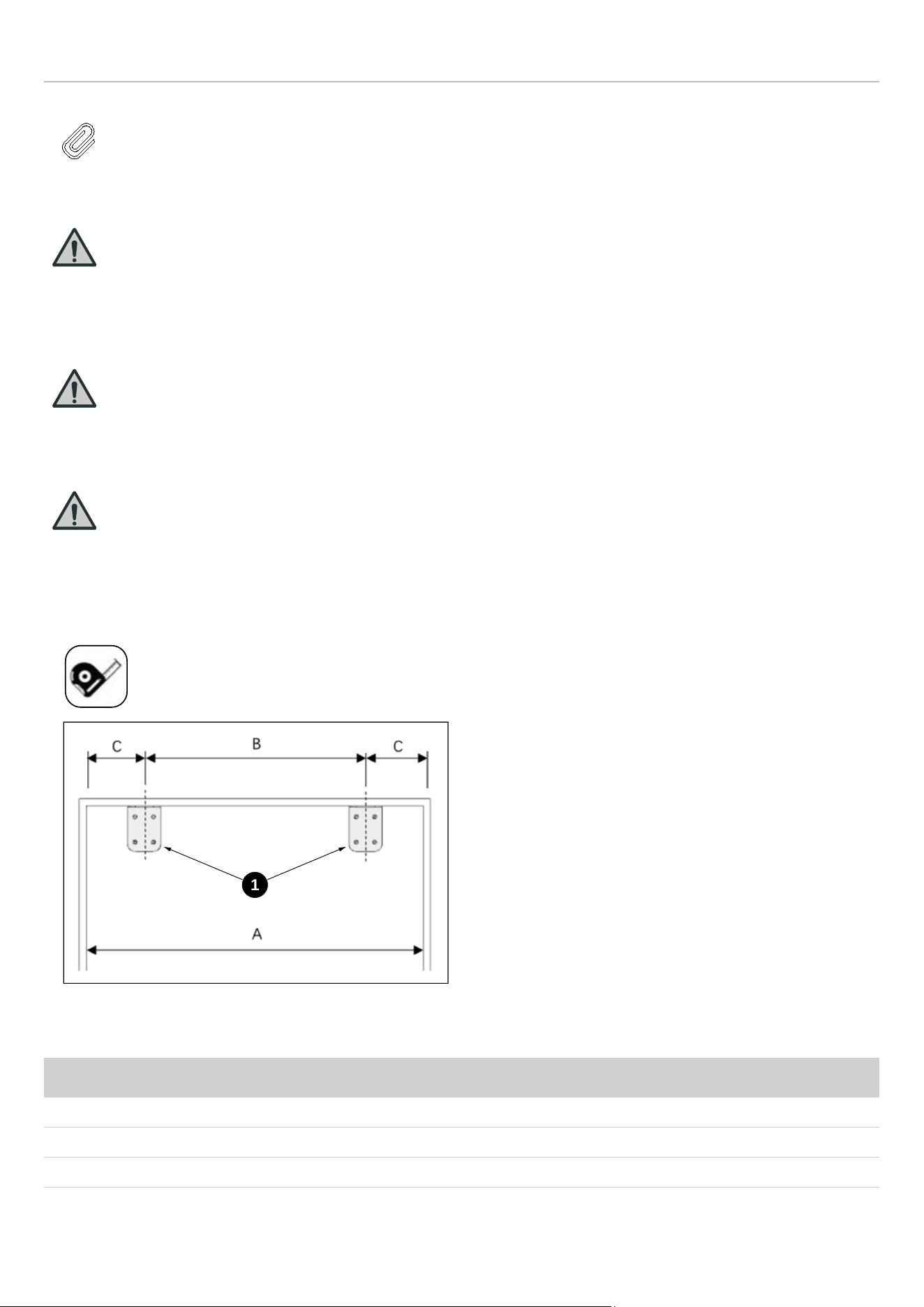
MOUNTING THE ANTI-TIP BRACKETS
WARNING
If the unit cannot be secured to the
cabinetry (which in turn must be secured to
wall) to prevent tipping, make sure to use
the supplied anti-tip brackets in order to
prevent the appliance from tipping over.
WARNING
Make sure that there is no electrical or
water connection in the adjacent cabinets
into which the mounting screws will be
screwed to secure the refrigerator.
WARNING
Please remember to use the necessary
protective equipment when drilling holes in
the wall and performing the installation.
• Use a tape measure to mark the wall for installation of
the anti-tip brackets.
Fig. 24
• 1 Anti-tip bracket, on the wall
CATEGORY REF18WCBPLV /REF18WCBPRV REF24WCBPNV
A
18″ (457 mm) 24″ (609 mm)
B
11 5/8″ (295 mm) 17 5/8″ (447 mm)
C
3 3/16″ (81 mm) 3 3/16″ (81 mm)
1
28
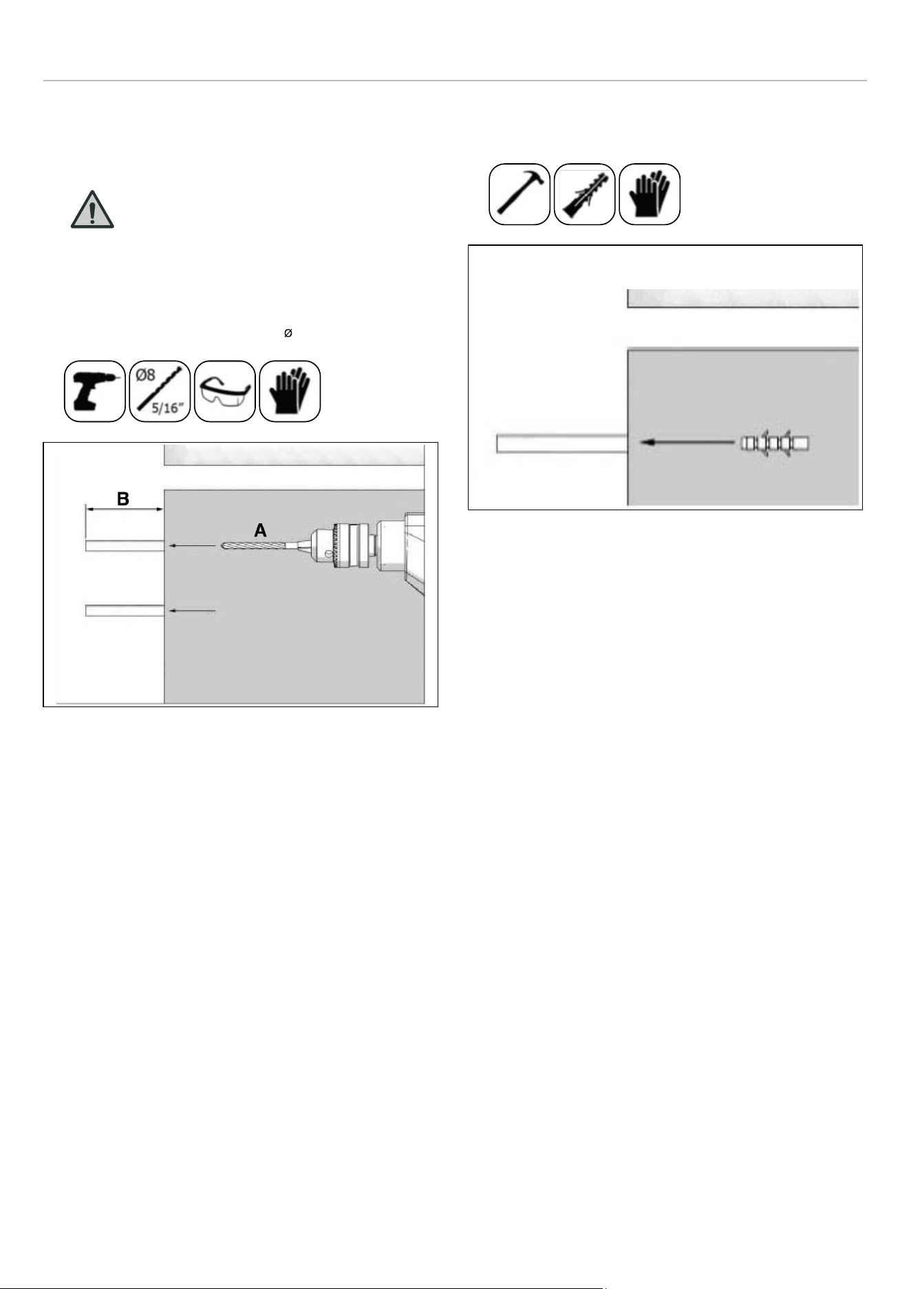
INSTALLATION INSTRUCTIONS
• For the most secure installation, use a stud-finder to
secure the anti-tip brackets in wall studs. If no studs are
present at the correct installation location, follow the
instructions below.
WARNING
Always make sure that the area to be
drilled into is free of any waterlines or
electrical circuits, which could cause
damage, injury, or death.
• Use a drill to create holes for wall anchors (#2) at the
marked points 7.9 mm (5/16″ Ø), 8 mm).
Fig. 25
A. 5/16″ (Ø8 mm)
B. > 62 mm
• Use a hammer to install the wall anchors (#2) if no stud
is present.
Fig. 26
• Install the brackets (#1) in place, using 4 screws for
each.
29
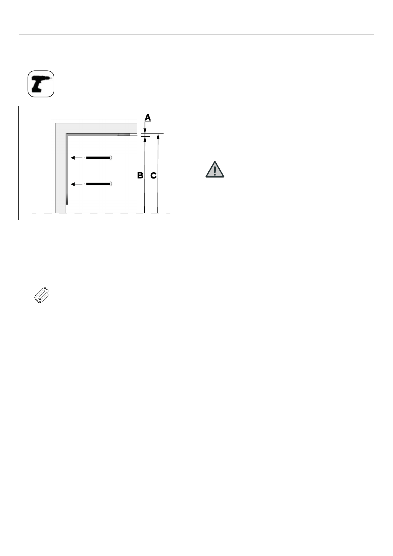
INSTALLATION INSTRUCTIONS
• You must use both (two) brackets to ensure that the
appliance is safely supported.
Fig. 27
A. 5/32″ (4 mm)
B. 83 27/32″ (2130 mm)
C. 84″ (2134 mm)
NOTE
If you are not confident that the supplied
connectors and anti-tip brackets are
mounted on the wall as securely as they
should be, you can use alternative anti-
tip methods.
If there is a cabinet panel behind the
back wall of the refrigerator, make sure
that it is securely fastened to the wall.
For this, you need to be sure that the
back wall of the cabinet panel is affixed
to a wall stud.
Alternative anti-tip method:
If the anti-tip brackets cannot be mounted securely, you
must use the alternative method below. For this method,
you can use wooden boards to avoid the risk of tipping
over.
They must be installed as illustrated in the figure below.
There must be no clearance between the appliance and the
wooden support.
The minimum section dimensions of the wooden support
must be 3″ x 4″ (76 mm x 102 mm). The width of the
support must be equal to the clearance where it will be
installed. This can be achieved using one 4″ x 4″ (102 mm x
102 mm) or two 2″ x 4″ (51 mm x 102 mm) pieces of
framing lumber.
The calculation of blocking depth is based on a standard
niche depth. If the depth of the niche is greater than 24″ (
610 mm), ensure the blocking overlaps the upper rear
fridge body by 2″ (51 mm).
Position the wooden support, mark the location on the rear
wall, select suitable screws and mount it securely.
WARNING
The quantity and type of screws or
fasteners to be used for affixing wooden
blocking must be suitable for ensuring a
secure connection to the rear wall.
A
B
C
30
INSTALLATION INSTRUCTIONS
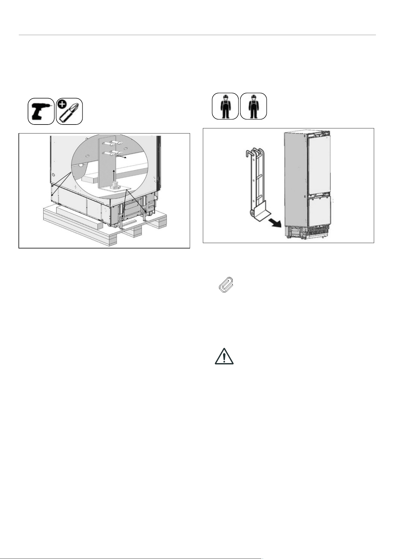
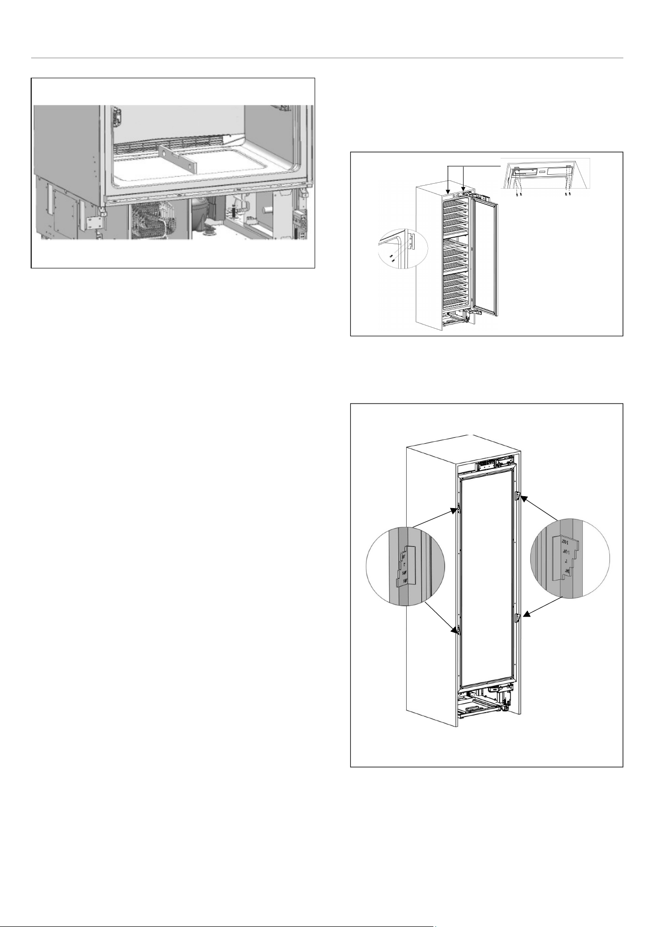
INSTALLATION IN THE CABINET
Taking the Refrigerator from the Wooden Pallet
• Remove the brackets which secure the refrigerator to
the wooden pallet as shown below.
Fig. 28
• Slowly tilt the refrigerator back and remove it from the
pallet, taking care not to damage the underside of the
unit. When transporting the unit, always carry it from the
sides to ensure that the unit's feet remain on the base of
the appliance dolly.
Fig. 29
NOTE
Exercise extreme caution when handling
the unit, as the underside of the fridge
has components vital to its proper
operation; damage to these components
could result in a malfunction or potential
leakage of condensate and damage to
floors.
CAUTION
The risk of tipping over is high from this
point forward. You should not open the
doors until the product is placed into the
cabinet.
31
INSTALLATION INSTRUCTIONS
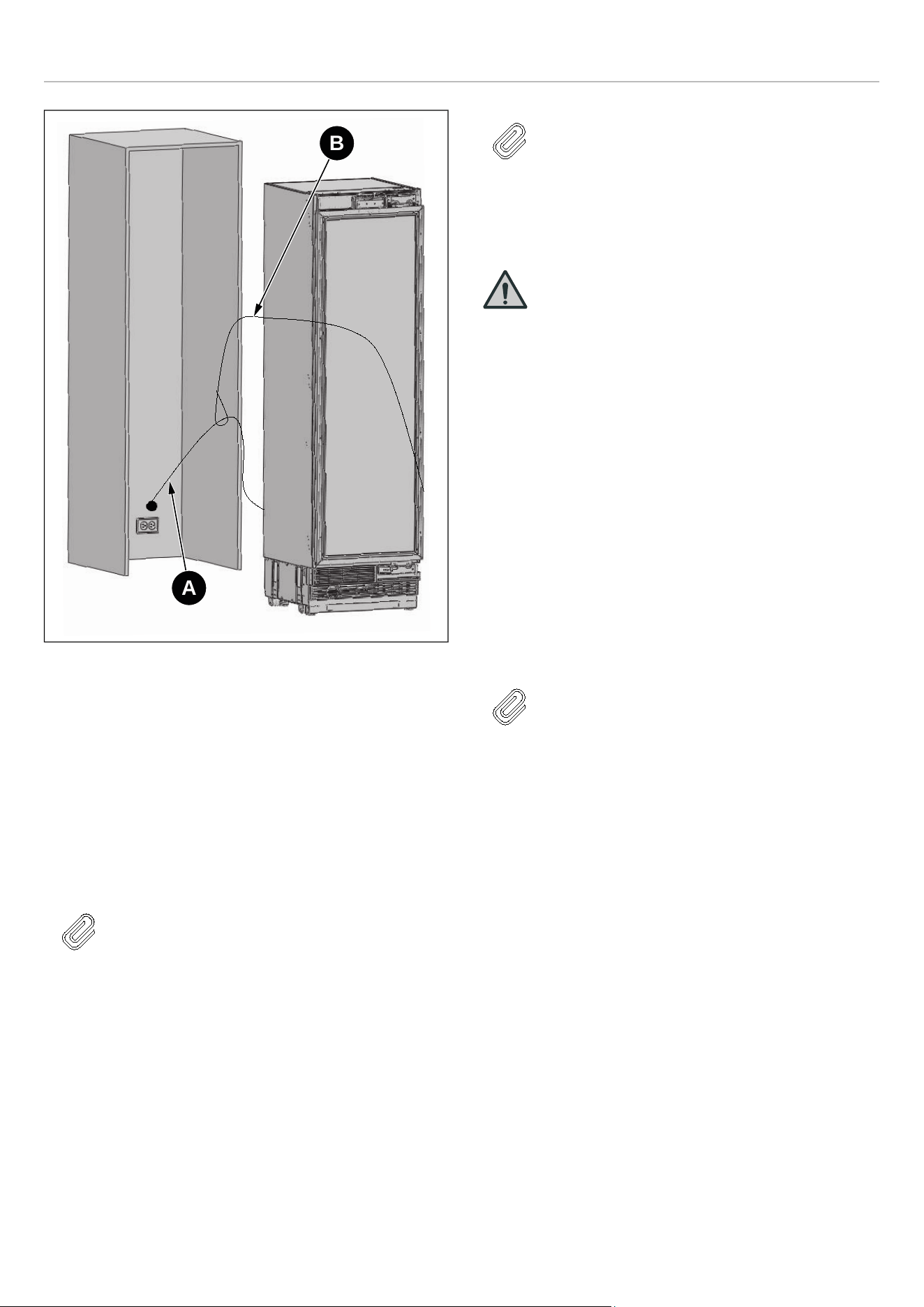
Fig. 30
• A Power cord
• B Nylon cord
• C Move to wall
• D Water hose
Connect the electrical plug to the power outlet. Turn on the
unit to ensure it has power. (To see if the product is
operating, check if the lamps in the freezer compartment
are on or off).
NOTE
Protect the front edges of the cabinet niche
with masking tape; this will help protect
them from damage when pushing the unit
back into the niche. Use some packing tape
to secure the excess electrical cord to the
back of unit to prevent slack from catching
under the unit during installation.
NOTE
The unit's plug must be accessible after
installation. If the plug is not accessible
after installation, the power must have a
dedicated circuit breaker which can be
accessed to cut power off using the main
switch.
WARNING
• Make sure that the power cord does not
get wedged in when placing the product.
• Push the product carefully towards
the cabinet to position it; the unit
should slide into the niche with
relative ease. If you experience
resistance while placing the product
in the cabinet:
• The floor might be uneven.
• The adjustable feet might be loose
(please see the relevant section to
learn how to adjust the adjustable
feet).
• You must attach the freezer door
temporarily to align the product before
placing it.
NOTE
Use the upper edges of the fridge and
freezer doors to align the unit in the niche
opening.
Adjustment of other edges is explained in
the following pages.
A
B
32
INSTALLATION INSTRUCTIONS
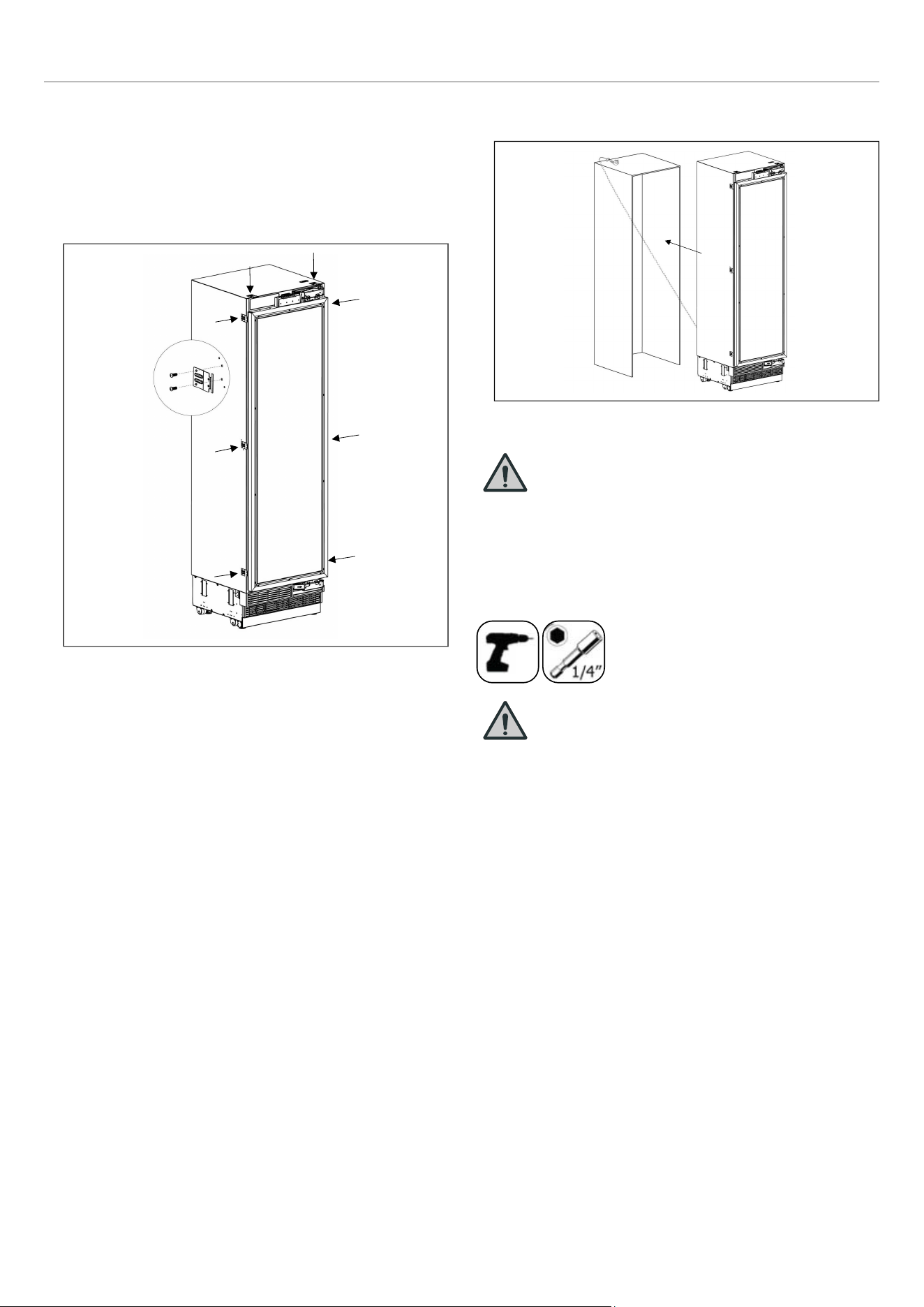
SCREWING THE SIDE AND UPPER
BRACKETS
Fix the bracket furniture to the unit, where 2 on the top, and
3 on every side.
• Use the truss washer head screws(M4*12) to tighten.
Fig. 31
• Push the product carefully towards the cabin to place it.
Fig. 32
WARNING
The plug of the product must be accessible
after installation
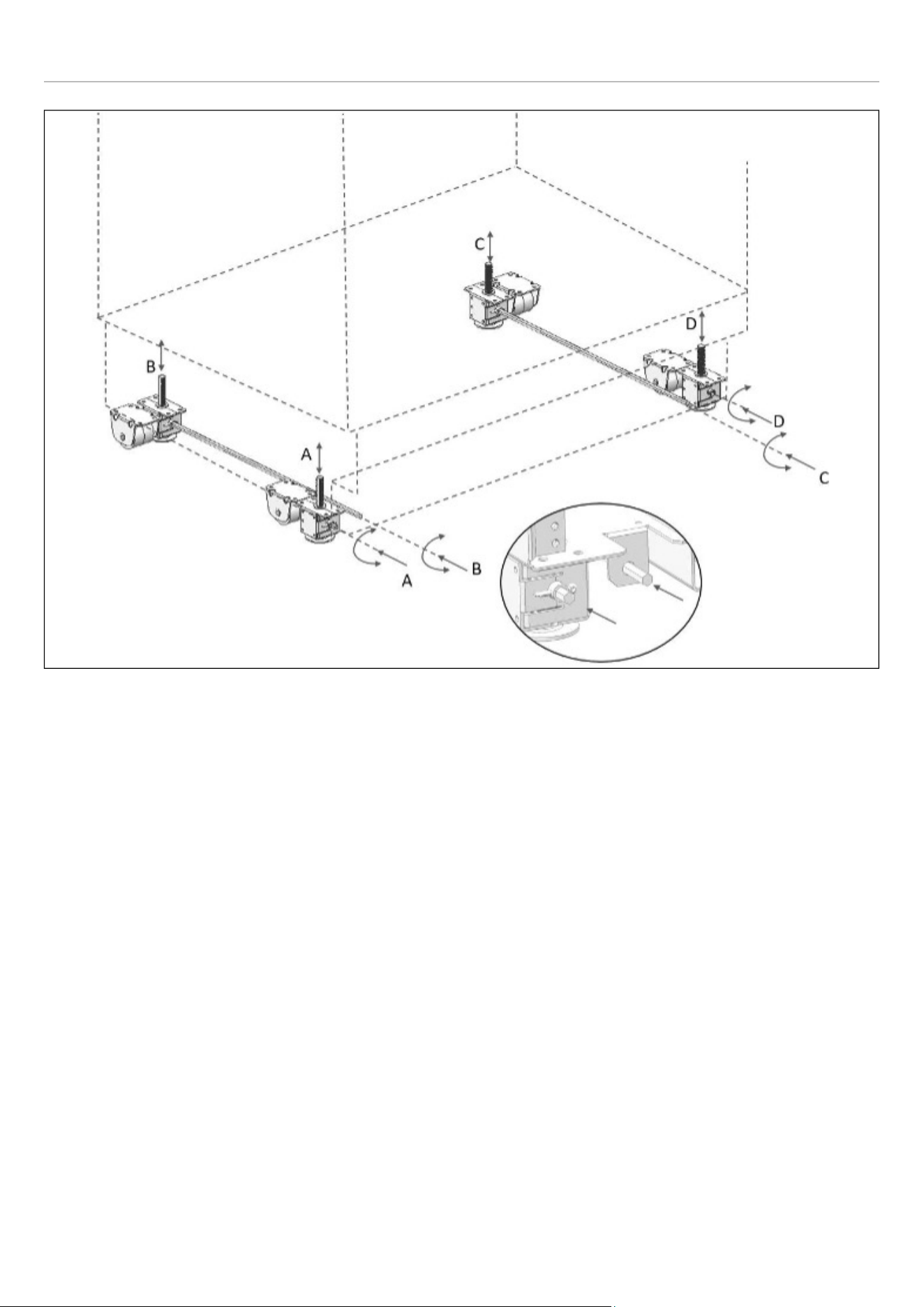
ADJUSTING THE HEIGHT
• Use the adjustable leg mechanism to raise, lower and
level the unit in the niche as per the diagram below.
WARNING
Once the unit is pushed into the niche,
raise the front feet first; this will reduce the
risk of the unit tipping forward during the
height adjustment process.
The maximum height that the adjustable
feet can reach is 40 mm (1 9/16″).
33
INSTALLATION INSTRUCTIONS
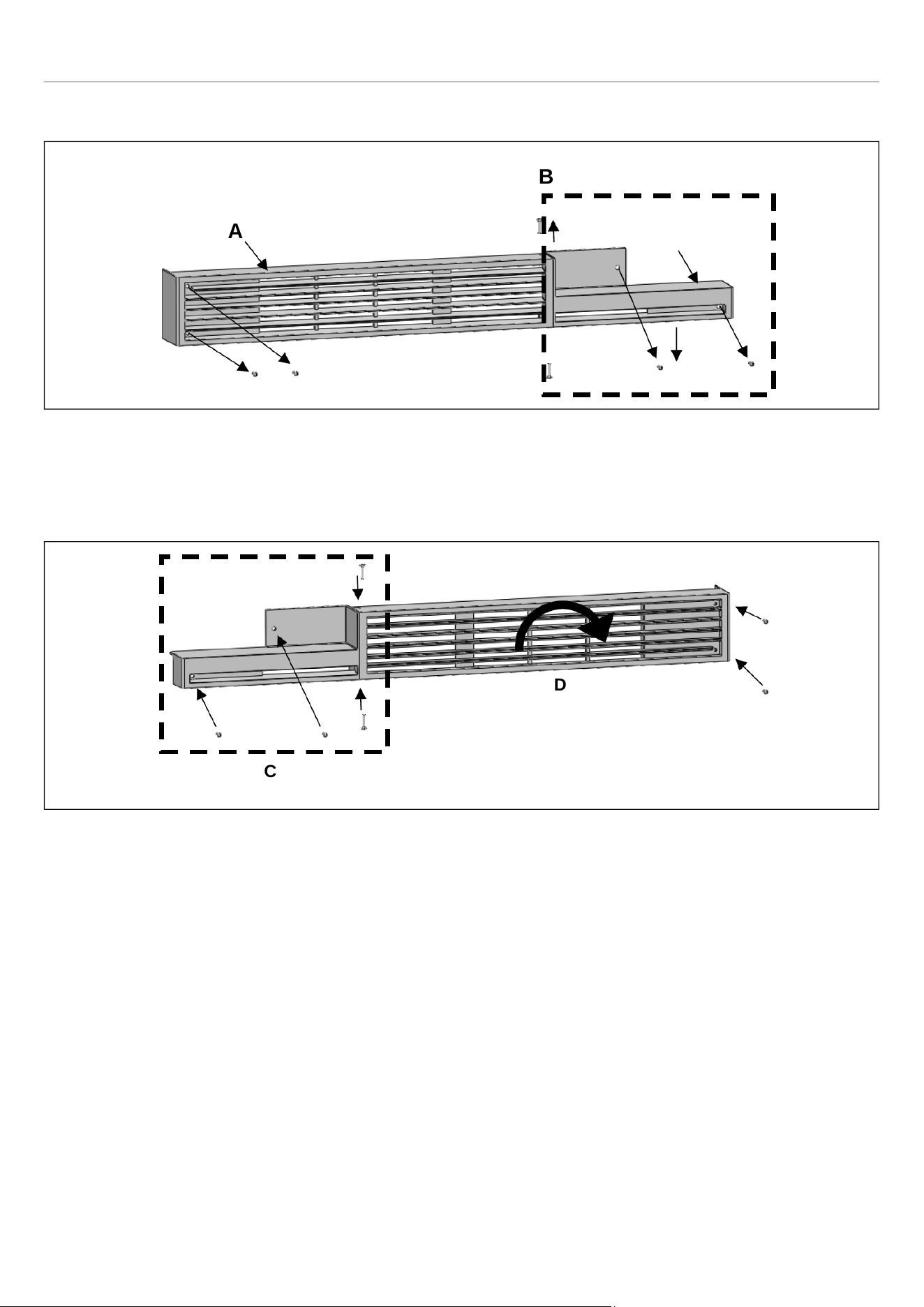
ATTACHING THE VENT HOLE ASSEMBLY
Use 5 screws to attach the vent hole assembly.
Fig. 37
ATTACHING THE DECORATIVE PARTS
Attach the side closing parts onto the right/left/upper
connection brackets.
Fig. 38
CATEGORY A
REF18WCBPLV /
REF18WCBPRV
18″ (457 mm)
REF24WCBPNV
24″ (609 mm)
Fig. 39
A. 85 ″ (2159 mm)
B. 24 ″ (617 mm)
A
A
B
A
B
36
INSTALLATION INSTRUCTIONS
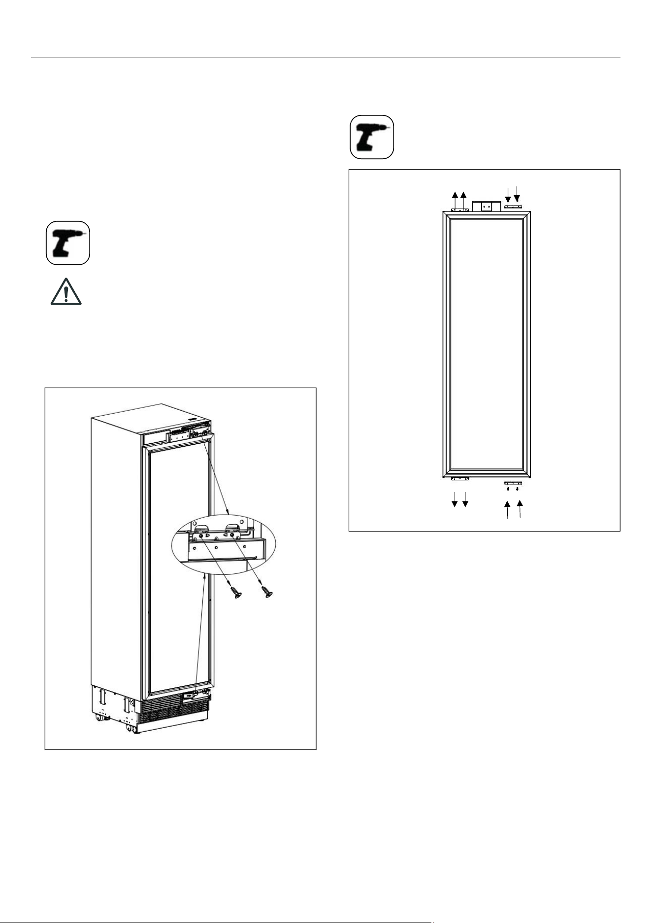
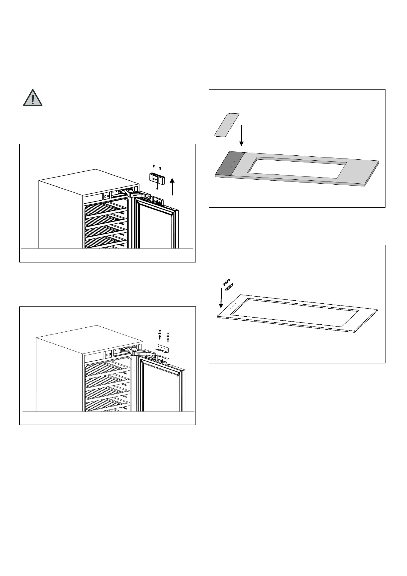
REMOVING THE PANEL-ADJUSTMENT
MECHANISMS ON THE REFRIGERATOR
Remove screws to take out the top hanger bracket cover.
WARNING
There is a magnet on the top hanger
bracket cover. This is a functional part for
the operation of the product. It should not
be confused with the low hanger
Fig. 40
Remove the upper and lower adjusting mechanism
assemblies from the door.
Fig. 41
PREPARING FURNITURE DOOR
When marking, you can use the "Furniture door preparation
template" provided with the product.
Fig. 42
Install cradles using the chipboard screws.
Fig. 43
37
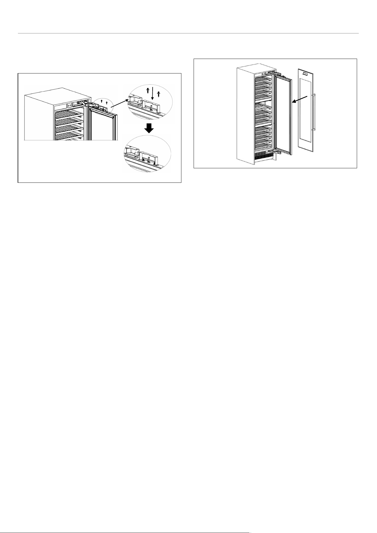

INSTALLATION INSTRUCTIONS
How to align the furniture door upper part with bolts.
• Attach and screw the upper decoration cover.
Fig. 47
• The left and right are secured by installing screws
(ST4x35).
Fig. 48
LIMITING PINS
The refrigerator door can open up to a maximum of 115°.
If the door panel thickness exceeds 1 1/2″ (38 mm), the
door should not open more than 90°. In such case, or if the
refrigerator is placed next to a wall, a 90° limit pin should be
installed on the upper and lower hinges.
Ensure the pin is fully seated in the bracket; otherwise, the
door will not close properly.
Fig. 49
40
INSTALLATION INSTRUCTIONS
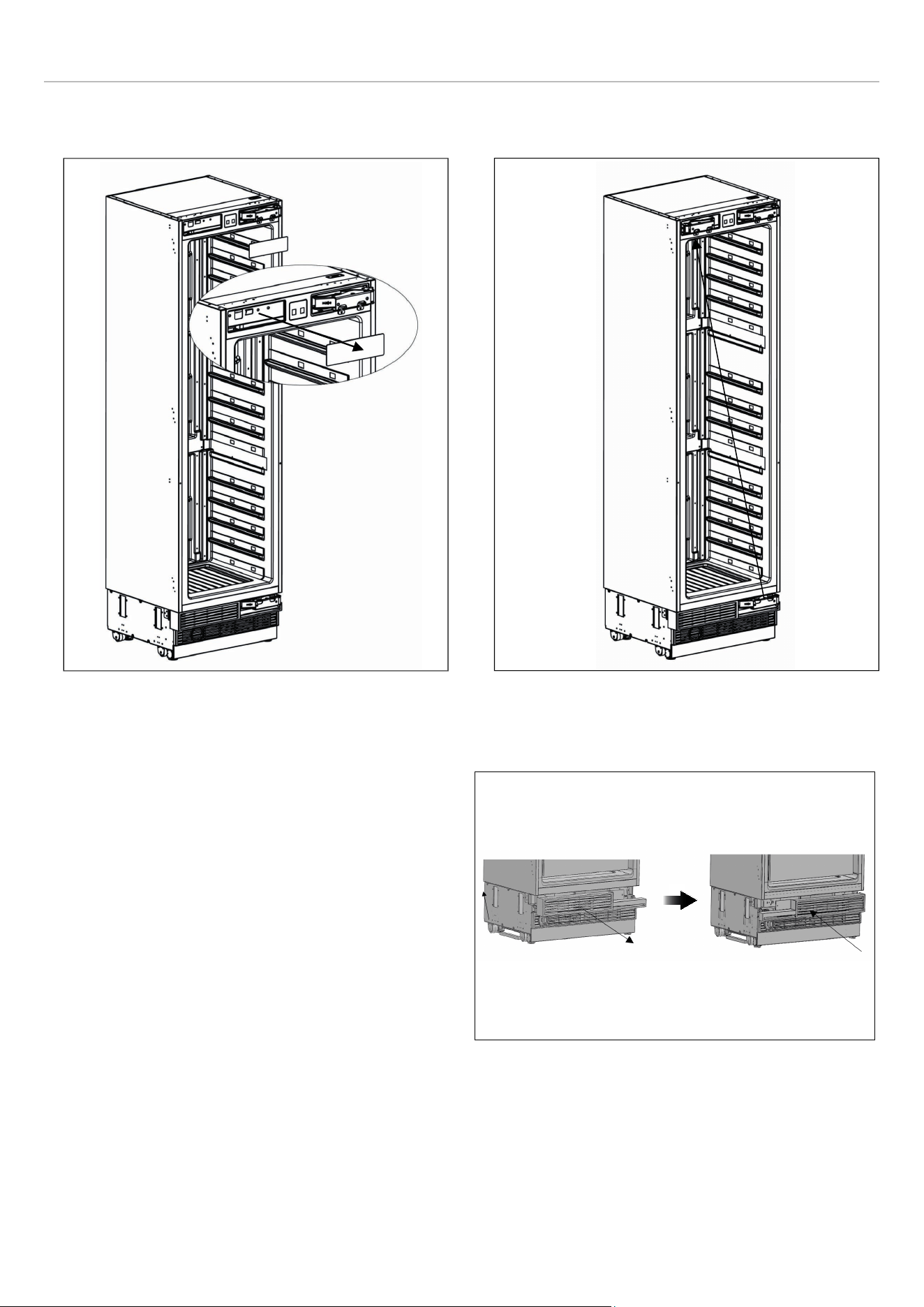
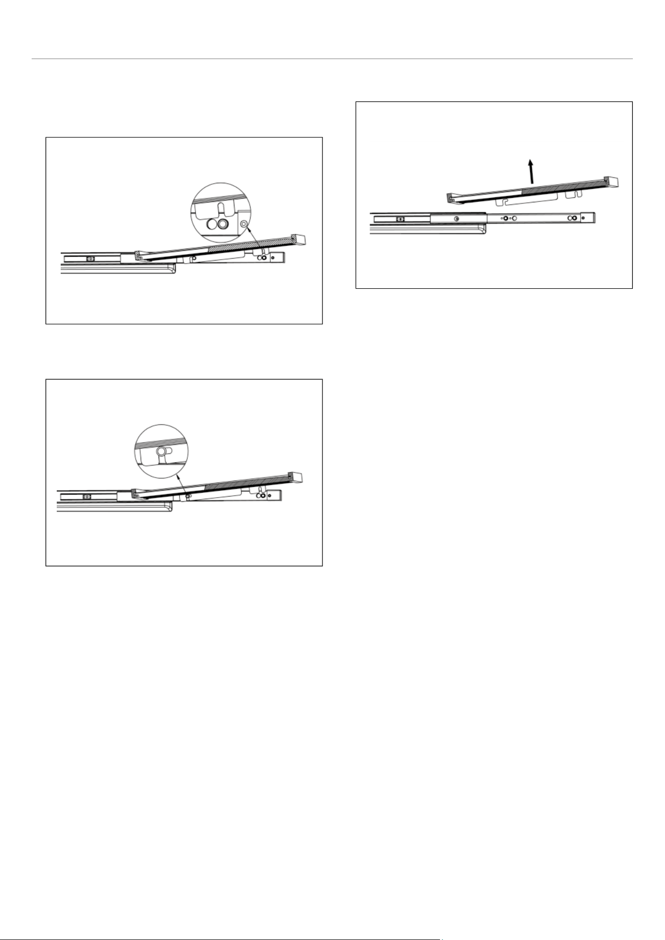
REMOVING THE SHELVES
1) Pull the wine shelf out of the telescopic glides at the
front.
2) Pull the wine shelf forward. The telescopic glides fixing
post is locked at the back in the position shown in the
gure.
3) Pull up the shelf to remove it.
ENSURING THE DOOR SEALS CORRECTLY
It is normal for the seal to be compressed after the door has
been reversed. With the door closed, use a hair dryer to
expand the seal and fill the gap between the door and the
body of the appliance. Take care not to hold the hair dryer
too close to the appliance, which could damage the seal.
A distance of approximately 10 cm should be suitable.
When completed, allow the seal and door to cool before
touching them. Once done, the seal should remain in
position.
41

USE
BEFORE FIRST USE
Remove all exterior and interior packaging. Allow the
appliance to stand upright for at least 24 hours prior to
switching the power on.
This will reduce the possibility of a malfunction in the
cooling system caused by handling during transportation.
• Clean the interior of the refrigerator as recommended in
the CLEANING AND CARE section. Before you turn on
the appliance, make sure that the interior is dry.
• Plug the appliance into a grounded socket. The interior
lighting comes on when the door is opened.
• Run the wine column for 6 hours before placing any
bottle in it and do not open its door unless it is
necessary.
NOTE
You will hear a noise when the compressor
starts up. The liquids and gases sealed
within the refrigeration system may also
cause noise, even if the compressor is not
running. This is quite normal.
NOTE
The front edges of the appliance may feel
warm. This is normal. These areas are
designed to be warm in order to prevent
condensation.
During operation, you may hear some absolutely normal
noises:
• Buzzing: The refrigerator is running. The fan of the air
recirculation system is running.
• Bubbling, humming or gurgling noises: refrigerant is
flowing through the pipes.
• Clicking: motor is turning on or off.
The door on the 24″ (60 cm) wide wine column appliance
can be opened from either the left or the right side. The unit
is delivered with the door opening on the left side. Should
you wish to open the door from the right, follow the
instructions included in this manual in the REVERSING
THE DOOR (IF APPLICABLE) section.
If you have received a damaged product, immediately
contact the dealer or distributor from which you purchased
the product.
Carefully read and follow these instructions for the
installation, use and maintenance of the appliance.
Read the troubleshooting section of this manual, which will
help you diagnose and solve the most common problems.
42
USE
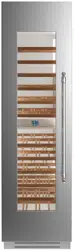
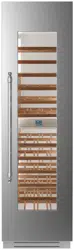
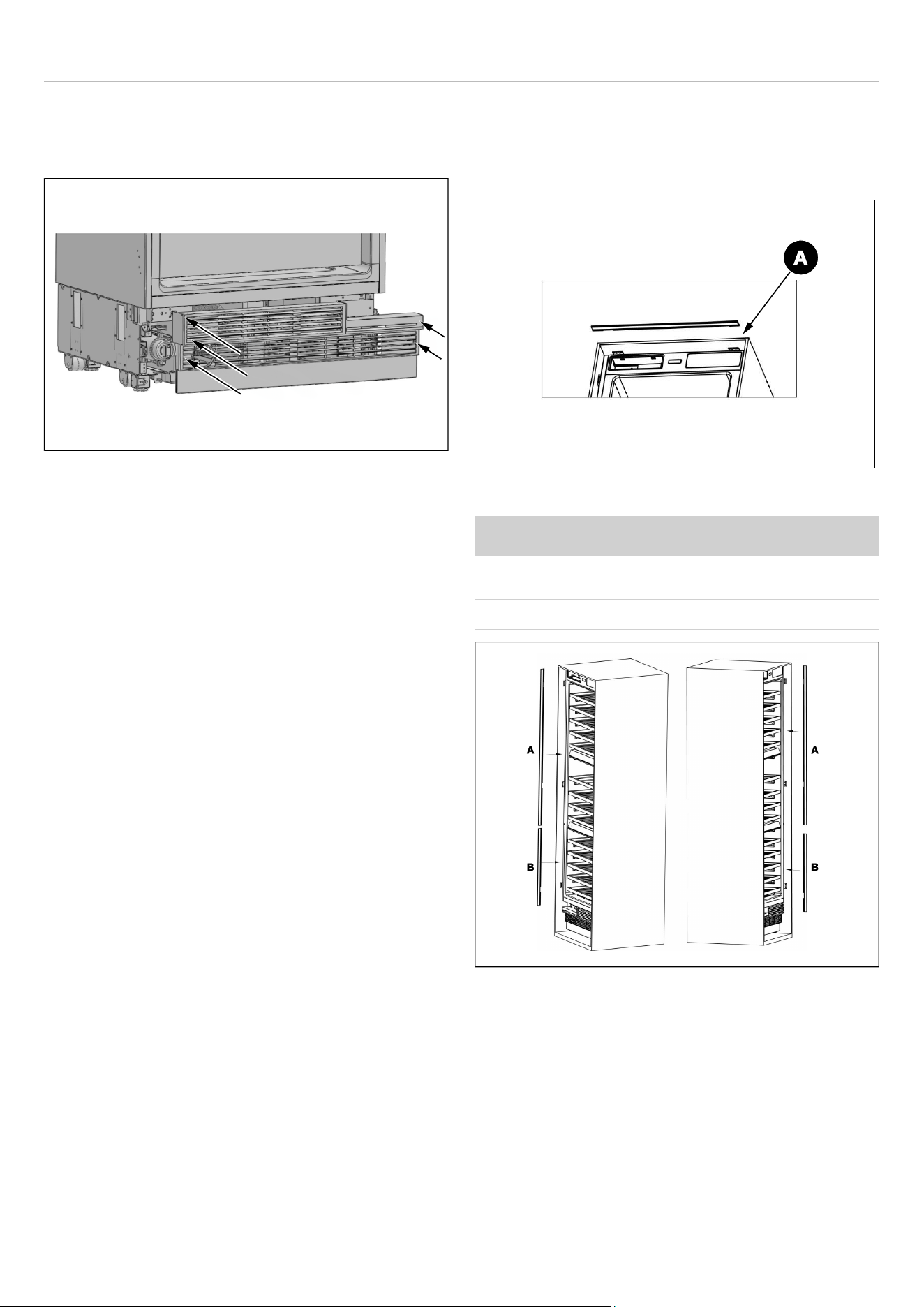
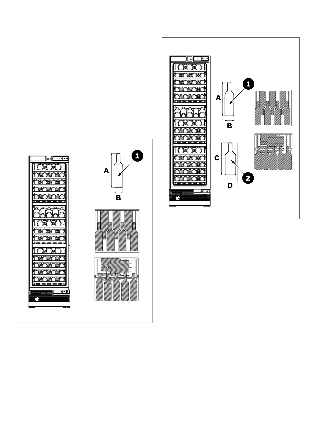
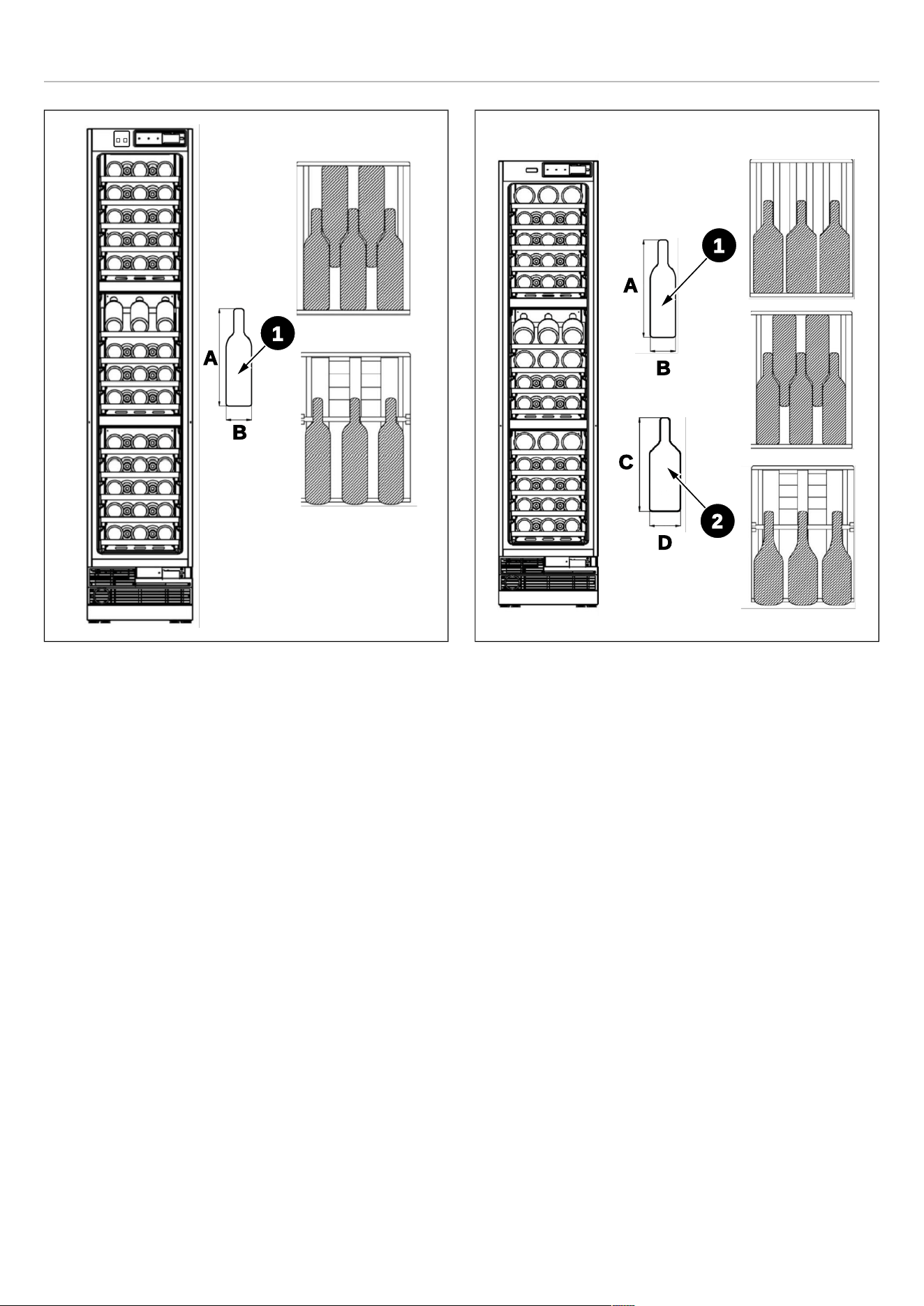
INTERNAL STORAGE
This wine column features 3 independent temperature
zones, each adjustable from 41 to 68℉ (5 to 20℃).
The figures in this section show two different loading
patterns. Follow the one best suited to your needs.
The wooden shelves can be removed to increase the load
capacity, but make the appliance less practical for everyday
use. To remove a shelf, see the REMOVING THE
SHELVES paragraph.
The most energy-saving configuration requires the shelves
to be installed in the appliance; please see the pictures
above.
Fig. 50 BOTTLE STORAGE A REF24WCBPNV
Fig. 51 BOTTLE STORAGE B REF24WCBPNV
A. 11 13/16″
B. 3″
C. 11 13/16″
D. 3 3/4″
1
A
B
A
C
B
D
1
2
43


USE
CARBON FILTER
Three built-in carbon filters serve as a natural barrier
against harmful odors, ensuring the protection of your
beverages.
To maintain optimal performance, it is recommended to
replace the carbon filter every 3 to 6 months, depending on
the unit’s exposure to odors.
If the unit is situated in a kitchen, replacing the filter every
three months is ideal.
To remove the carbon filter, simply turn it counterclockwise
to unlock it from the rear panel.
Replacement filters can be ordered from your dealer of
choice.
Fig. 54
47

USE
RECOMMENDATIONS FOR STORING AND
SERVING WINE
To best appreciate the organoleptic qualities of each wine,
it is necessary that storage and consumption be carried out
at certain temperatures.
The following table summarises the most suitable storage
temperature for each type of wine. It is recommended,
particularly for more valuable bottles, to appropriately follow
the instructions provided by the producer.
TYPE OF WINE STORAGE TEMPERATURE (℉℉)
Young and light white wines
50 - 54
Mature and structured white wines 54- 57
Aromatic white wines 46- 50
Young and light rosé wines
50- 54
Mature, full-bodied rosé wines
54- 57
Young red wines
50 - 57
Young, slightly tannic and light red wines
57- 61
Mature, tannic and full-bodied red wines
16 - 18
Very mature, tannic and full-bodied red wines
61- 64
Sweet and aromatic sparkling wines
46- 50
Sweet and aromatic red sparkling wines
50- 54
Charmat method sparkling wines
46- 50
Long Charmat method sparkling wines
50- 54
Classic method sparkling wines
46- 50
Classic “Millesimato” method sparkling wines
50- 54
Dry and semi-dry sparkling wines
46- 50
Semi-sparkling wines
50 - 54
Superior sweet sparkling wines
50 - 54
Fortified, dessert or straw wines
50 - 64
48

USE
WHITE WINES
White wines are normally not served at high temperatures,
since they are generally more acidic that red wines and not
very tannic, which is why they are more enjoyable at low
temperatures.
These wines should preferably be stored and served
between 10 ℃ and 14 ℃ (50 ℉ and 57 ℉). Young, fresh
and aromatic wines can also be served at 10 ℃ (50 ℉),
while less aromatic ones are recommended at 12 ℃
(54 ℉). Temperatures between 12 ℃ and 14 ℃ (54 ℉ and
57 ℉) are suitable for soft, mature white wines aged for a
few years in the bottle. Higher temperatures would favour
the enhancement of the sweet character of the wine, to the
detriment of the acidity and flavour that are considered
pleasant and desirable characteristics for this type of wine.
ROSÉ WINES
Rosé wines are generally served at the same temperature
as white wines. However, it should be noted that these
wines may contain a certain amount of tannins and it may
therefore be preferable to taste them at higher
temperatures so as not to make them too astringent.
Consequently, they are served between 10 and 12 ℃ (50
and 54 ℉) if young and fresh and between 12 and 14 ℃
(54 and 57 ℉) if more robust and mature.
RED WINES
Containing more tannins and being less acidic, red wines
are usually served at higher temperatures.
Younger and less tannic wines are generally served
between 14 and 16 ℃ (57 and 61 ℉), while fuller-bodied
and tannic wines can be served at 16 ℃ (64 ℉), and
exceptionally even at 18 ℃ (64 ℉). Some wines aged for
years in the bottle, still full-bodied and tannic, can be
served at 18 ℃ (64 ℉) or even at 20 ℃ (68 ℉). Young red
wines that are low in tannins and less structured can be
enjoyed at lower temperatures, between 12 and 14 ℃ (54
and 57 ℉).
CLASSIC OR CHARMAT METHOD SPARKLING WINES
Given the high variety of existing sparkling wines, it is
difficult to give valid recommendations for all.
In general, sweeter and more aromatic sparkling wines
should be served at lower temperatures, up to 8 ℃ (46 ℉),
due to their aromaticity. More tannic sparkling wines can be
served at higher temperatures, up to 14 ℃ (57 ℉).
Dry Charmat or Martinotti method sparkling wines, such as
some Proseccos, should generally be served between 8
and 10 ℃ (46 and 50 ℉). Classic method sparkling wines
and 'méthode Champenoise' such as Champagne are also
normally served at these temperatures but, for sparkling
wines aged for some time such as Millesimati, one can go
up to 12 ℃ (54 ℉) to favour the development of complex
aromas.
However, it is advisable, especially for the finest wines, to
follow the producer's recommendations, which are printed
on the bottle.
SPARKLING WINES
For semi-sparkling wines, the same temperature
indications apply as for Classic or Charmat method
sparkling wines and are generally served between 10 and
12 ℃ (50 and 54 ℉). For dry and semi-dry sparkling wines,
a slightly lower serving temperature of between 8 and 10 ℃
(46 and 50 ℉) is recommended.
FORTIFIED, DESSERT OR STRAW WINES
This type of wine can be served at temperatures between
14 and 18 ℃ (61 and 64 ℉) depending on personal taste
and, to attenuate the sweet taste and high alcohol content,
it can also be served at 10 ℃ (50 ℉).
Dry liqueur wines, such as Marsala for example, contain so
much sugar that they are not perceived on the palate. For
these wines, the serving temperature should be set
according to what you want to emphasise. If you prefer to
accentuate the sweetness of the wine, the complexity of its
bouquet and its austerity, it is best to serve it at a high
temperature, between 14 ℃ and 18 ℃ (61 and 64 ℉),
remembering that this will also enhance the alcohol
component. If you want to enhance their freshness more,
they should be served at a lower temperature of between
10 ℃ and 14 ℃ (50 and 61 ℉). Dry, fresh, young liqueur
wines can also be served at a cooler temperature of less
than 10 ℃ (50 ℉) in order to significantly reduce the
perception of alcohol. However, the lower the serving
temperature, the lower the perception of aromas will be.
The pleasantness and complexity of aromas typical of
these wines is a welcome and interesting characteristic:
serving them too cold means sacrificing this important
aspect.
49
USE
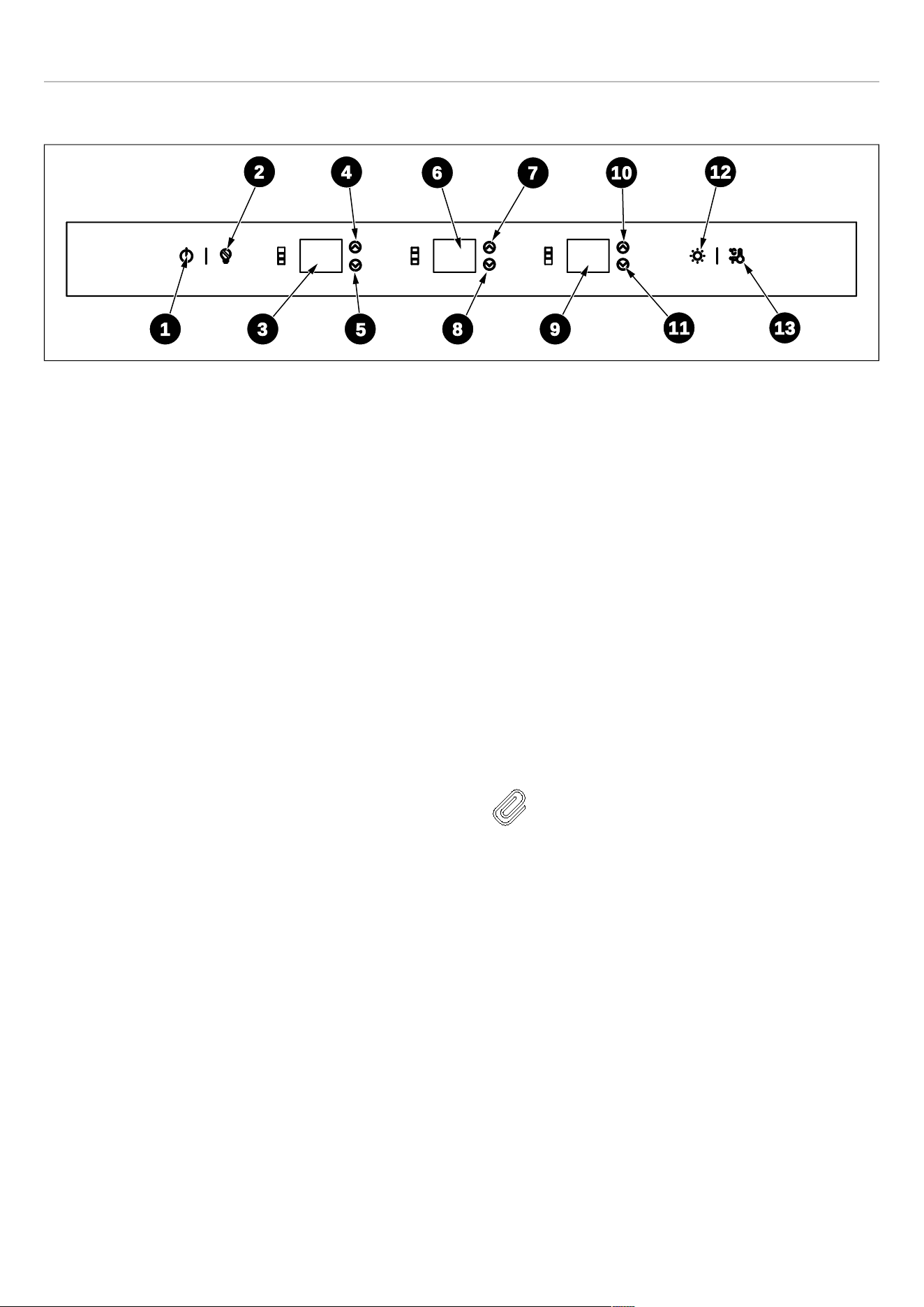
CONTROL PANEL
Fig. 55
1) On/Off Button
2) Sabbath Mode
3) Upper Zone Temperature
4) Upper Zone Temperature Increase Button
5) Upper Zone Temperature Decrease Button
6) Middle Zone Temperature
7) Middle Zone Temperature Increase Button
8) Middle Zone Temperature Decrease Button
9) Lower Zone Temperature
10) Lower Zone Temperature Increase Button
11) Lower Zone Temperature Decrease Button
12) Light Button
13) Celsius and Fahrenheit Selection
ON/OFF BUTTON
Serves to switch the whole appliance On or Off. Press [1]
for 3 seconds to switch the appliance on/off. When
switched off, the appliance disconnects from all external
power sources and switches to standby status.
ENABLING/DISABLING THE CHILD LOCK
The child lock is a feature for preventing children from
changing the appliance's settings. Press buttons [12] + [13]
simultaneously to lock/unlock the control panel.
When the child lock is enabled, the temperature values in
the digital displays will flash simultaneously for 3 seconds,
accompanied by an acoustic signal to indicate that the
display is locked. Deactivate the child lock to change any
settings.
TEMPERATURE ADJUSTMENT BUTTONS
Press buttons [4] , [7] , [10] to increase the temperature
value by 1 degree with each press. Press buttons [5] , [8] ,
[11] to decrease the temperature value by 1 degree with
each press. The temperature can be set from 5 ℃ (41 ℉) to
20 ℃ (68 ℉) in each temperature zone.
NOTE
When changing the temperature of the
three zones, the displays will immediately
show the selected temperatures on of the
three zones. The actual temperatures
inside the zones will gradually change until
the desired set temperatures are reached.
The appliance will take some time to reach
the new set temperatures; this is normal.
10
7
6
4
2 12
11
98
5
31
13
50

USE
LIGHT COLOR SELECTION, LIGHT BRIGHTNESS
SELECTION AND ENTERTAINMENT MODE
The switching on/off of the LED lights depends on the door
opening/closing. When the door is opened, the lights switch
on automatically. When the door is closed, the lights switch
off to save energy.
For selecting the light color, press button [12] to change the
color of the LED illumination between amber, blue or white.
Press the [12] button for 3 seconds to activate the
entertainment mode and keep the light constantly on even
when the door is closed. The displays of the three
temperature zones will show 'ON' for 5 seconds. After
5 seconds, the digital displays will show again the set
temperatures in the 3 zones.
To adjust the brightness of the lights, press [12] until all
digital displays of the three temperature zones show "ON”.
Within 5 seconds, press [4] , [5] , [7] , [8] , [10] , [11] to
adjust the brightness of the LED lights among seven levels,
in brightness increments from L1 to L7.
CELSIUS AND FAHRENHEIT SELECTION
To switch between Celsius and Fahrenheit, press button
[13]. Each press makes a switch. Celsius is set as the
factory default.
SHOWROOM MODE
Press [1] + [2] buttons simultaneously for 3 seconds to
enable the function.
This mode is used when the refrigerator is on display in a
retail store or if you want to turn the cooling off and
deactivate all other functions except interior lighting. When
enabled, the digital displays of the 3 temperature zones will
all show “Sn”. If no button is pressed for 72 hours, the
mode will deactivate automatically. Press [1] + [2]
simultaneously to deactivate the showroom mode at any
time.
NOTE
Do not store any item while in showroom
mode, because the appliance then remains
at room temperature.
51

USE
SHABBAT MODE
Press [2] to enable/disable the function. When the Shabbat
Mode function is enabled, all lights, buzzers and digital
displays will be switched off. The compressor and fan will
continue to operate normally. The mode is automatically
deactivated after 96 hours of operation. If the device is
switched off, the status is maintained. Press [2] to
deactivate Sabbath mode at any time.
NOTE
When you adjust the temperature on the
control panel, it will display the current
temperature. The reading will gradually
change to reflect the internal temperature
until it aligns with your desired setting.
Please note that it may take some time for
the wine cellar to reach the new
temperature, which is entirely normal. You
do not need to adjust the desired
temperature simply because the display is
not immediately showing your preference.
If there is moisture or liquid on the control
panel, it may not function properly. Please
wipe the surface with a dry cloth and try
again.
POWER FAILURE MEMORY FUNCTION
TEMPERATURE RANGES:
• Upper Zone: 41℉ - 68℉ (5-20℃)
• Middle Zone: 41℉ - 68℉ (5-20℃)
• Lower Zone: 41℉ - 68℉ (5-20℃)
52

CARE AND MAINTENANCE
WARNING
Always disconnect the appliance from the
mains power before performing any
cleaning or maintenance.
LED LIGHT REPLACEMENT INSTRUCTIONS
To provide optimum interior lighting, LED strips illuminate
the appliance from the top and sets of LED lights directly
illuminate different areas.
In case of malfunction and/or wearing out of the lighting
system, repairs should be carried out by a qualified Service
technician.
CLEANING THE INTERIOR SURFACES
To clean the inside of the wine column, open the door and
remove the shelves. Wipe the inside of the unit with a clean
cloth and a mild detergent, or with a soft sponge and a
solution of bicarbonate of soda and lukewarm water. Do not
use abrasive products or detergents. After washing, rinse
and dry thoroughly.
Clean the wooden shelves with a soft, slightly damp cloth.
Avoid using soaps, detergents and/or sponges that can
damage both wooden and steel surfaces. Dry the shelves
carefully before placing them back in the wine column.
WARNING
Do not use vinegar, rubbing alcohol or any
alcohol-based cleaning agent on any of the
interior surfaces.
If the appliance is not going to be used for an extended
period of time, unplug and clean the appliance. The doors
should be left slightly ajar to prevent the formation of
mildew and unpleasant odours.
CLEANING THE EXTERIOR SURFACES
To clean the door and cabinet, use a mild detergent
solution composed of two tablespoons of baking soda per
quart of lukewarm water. Refrain from using abrasive or
corrosive cleaning agents.
Avoid using solvent-based or abrasive cleaners. Use a soft
sponge for cleaning, rinse with clean water, and dry with a
soft towel to prevent water spots.
If the door panel is stainless steel, be aware that exposure
to chlorine gas and moisture may cause discoloration.
Clean the stainless steel with a cloth dampened in a mild
detergent and warm water solution.
Refrain from using abrasive or corrosive cleaning agents.
DEFROSTING
The wine column is designed with an automatic defrost
system. However, on colder settings, some frost may build
up. Additionally, the more humid the ambient conditions,
the more frost may build up. Keep the door closed as much
as possible and avoid opening the door unnecessarily to
minimize frost build-up.
If frost is preventing the door from closing properly, you
may need to power the unit o until the frost melts (possibly
up to 24 hours). Use a soft absorbent towel to dry the unit.
WARNING
Do not harm refrigerant tubing.
NOISES AND MEANING
This wine column may emit some normal sounds during
operation.
Hard surfaces such as the floor or walls may make the
sounds seem louder than they actually are.
In the list below you will find the most common sounds and
their causes:
• rattling: due to the flow of refrigerant or objects placed
on top of the appliance.
• loud or high-pitched sounds: the high-efficiency
compressor may emit sounds due to normal operation.
• splashing sound: due to water flowing from the
evaporator to the water container.
• gurgling sound: refrigerant flowing into the appliance.
• air noise: air can be heard being pushed over the
condenser by the condenser fan.
POWER FAILURE
Most power failures are resolved within a few hours and
should not affect the temperature of the appliance if the
number of times the door is opened is minimised. If the
power outage continues for a longer period of time,
appropriate measures must be taken to protect the
contents of your appliance.
53

TROUBLESHOOTING
If you have any problems with your appliance, please check
this troubleshooting section prior to calling Customer Care.
If the appliance is not working, check that:
• The appliance is receiving electrical power.
• The fuses in the home are intact and the fuse in the plug
has not blown.
• The appliance has not been turned off.
• The electrical outlet is functioning properly. To check
this, plug another electrical appliance into it to see if the
outlet is faulty.
If the appliance is working, but not very well, check
that:
• The appliance is not overloaded.
• The thermostat is set to an appropriate temperature.
• The doors are closing properly.
• The cooling system on the back of the appliance is clean
and free of dust and is not touching the rear wall.
• There is enough ventilation around the side and rear
walls.
If the appliance is not cold enough, check that:
• Temperature is not set too high.
• The appliance is not installed next to a heat source.
• The door is not opened too frequently or for long periods
of time.
• The door gasket seals properly.
• The appliance is not set on demo mode.
• The appliance has sufficient ventilation and ensure it is
installed according to the installation requirements
specified in this manual.
If the appliance is noisy or turns on and off frequently,
check that:
• The appliance is level and stable.
• The shelves are positioned correctly inside the
appliance.
• The room temperature is hotter than normal.
• The door gasket is properly sealed.
• The door is not opened too frequently or for long periods
of time.
• The appliance has sufficient ventilation and ensure it is
installed according to the installation requirements
specified in this manual.
NOTE
The coolant gas in the refrigerator may
make a slight bubbling or gurgling noise,
even when the compressor is not running.
NOTE
Some popping or cracking noises are
normal. They are caused by expansion and
contraction of the inside walls due to
temperature changes.
If the appliance is beeping, check that:
• The doors are closed. An alarm will sound after a door
has been open for 60 seconds.
If frost has formed in the appliance:
• The environment is too humid.
• The room temperature is too low.
• The door is being opened too frequently.
• The unit has an auto-defrost system but, under certain
conditions, manual defrosting may be required. If frost
periodically forms, try to run the refrigerator at a warmer
temperature setting, minimising the number of door
openings or unplugging the unit to allow the frost to melt.
• Check the door seal for any kinks, debris or damage. If
you notice any, and are unable to resolve the issue
yourself, contact Customer Care so that the seal can be
replaced.
• This can be due to the cabinet door(s) not being properly
fitted. If you are at all unsure, ask your installer to check
the cabinet doors.
If one or more of the LED units inside the appliance is
not working:
• Contact Customer Care to arrange a service visit.
If the body of the appliance is electrified:
• The unit is not properly grounded. Contact your
electrician to test your electrical grounding system.
54

ERROR CODES
When a malfunction occurs, contact a service technician for
repairs
EXPLANATION OPEN CIRCUIT CODE SHORT CIRCUIT CODE
Upper Zone In-cabinet probes
E1 E2
Upper Zone Frosting probe
E3 E4
Middle Zone In-cabinet probe
E5
E6
Middle Zone Frosting probe
E7 E8
Upper Zone In-cabinet probes
E9 E10
Lower Zone Frosting probe
E11 E12
NOTE
1) In the presence of a fault code, the
buzzer will sound an alarm ‘Tic’ ‘Tic’ ‘Tic’
three times in a row. The fault code will
flash on the display every 10 seconds,
and the alarm will activate.
If you want to release the alarm sound,
press the on/off key.
2) Whenever a key is pressed, the buzzer
sounds "Tic".
55


DU BUREAU DE NOTRE PRÉSIDENT
Cher nouveau propriétaire d’un appareil Bertazzoni,
Je tiens à vous remercier d’avoir choisi l’un de nos beaux produits pour votre
maison.
Ma famille a commencé à fabriquer des appareils électroménagers en Italie en 1882,
bâtissant une réputation de qualité d’ingénierie et de passion pour la bonne cuisine.
Aujourd’hui, nos produits se distinguent par leur mélange unique de design italien
authentique et de technologie d’électroménager supérieure. Notre mission est de
fabriquer des produits qui fonctionnent parfaitement et qui apportent de la joie à leurs
propriétaires.
En fabriquant de beaux produits, nous répondons au goût de nos clients pour un joli
design. En les rendant polyvalents et faciles à utiliser, cuisiner avec Bertazzoni
devient un réel plaisir.
Ce manuel vous aidera à apprendre à utiliser et à entretenir votre appareil
Bertazzoni de la manière la plus sûre et la plus efficace, afin qu’il puisse vous donner
la plus grande satisfaction pour les années à venir.
Profitez !
Paolo Bertazzoni
Président
57


VALIDITÉ DU MANUEL
Le manuel suivant est valable pour tous les codes produits mentionnés ci-dessous :
• REF24WCBPNV
• REF18WCBPLV
• REF18WCBPRV
59

60
SOMMAIRE
INFORMATIONS GÉNÉRALES . . . . . . . . . . . . . . . . . . . . . . . . . . . . . . . . . . . . . . . . . . . . . . . . . . . . . . . . . . . . . . . . . . . . . 61
MANUEL D’UTILISATION . . . . . . . . . . . . . . . . . . . . . . . . . . . . . . . . . . . . . . . . . . . . . . . . . . . . . . . . . . . . . . . . . . . . . . 61
INFORMATIONS DE SÉCURITÉ . . . . . . . . . . . . . . . . . . . . . . . . . . . . . . . . . . . . . . . . . . . . . . . . . . . . . . . . . . . . . . . . 62
PRENDRE SOIN DE L’ENVIRONNEMENT . . . . . . . . . . . . . . . . . . . . . . . . . . . . . . . . . . . . . . . . . . . . . . . . . . . . . . . . 64
ÉCONOMIE D’ÉNERGIE . . . . . . . . . . . . . . . . . . . . . . . . . . . . . . . . . . . . . . . . . . . . . . . . . . . . . . . . . . . . . . . . . . . . . . . 64
DÉPLACEMENT DE L’APPAREIL . . . . . . . . . . . . . . . . . . . . . . . . . . . . . . . . . . . . . . . . . . . . . . . . . . . . . . . . . . . . . . . 64
SPÉCIFICATIONS . . . . . . . . . . . . . . . . . . . . . . . . . . . . . . . . . . . . . . . . . . . . . . . . . . . . . . . . . . . . . . . . . . . . . . . . . . . . . . . . 65
ASPECT GÉNÉRAL . . . . . . . . . . . . . . . . . . . . . . . . . . . . . . . . . . . . . . . . . . . . . . . . . . . . . . . . . . . . . . . . . . . . . . . . . . . 65
CARACTÉRISTIQUES TECHNIQUES . . . . . . . . . . . . . . . . . . . . . . . . . . . . . . . . . . . . . . . . . . . . . . . . . . . . . . . . . . . . 65
TEMPÉRATURE AMBIANTE . . . . . . . . . . . . . . . . . . . . . . . . . . . . . . . . . . . . . . . . . . . . . . . . . . . . . . . . . . . . . . . . . . . 65
INSTRUCTIONS D’INSTALLATION . . . . . . . . . . . . . . . . . . . . . . . . . . . . . . . . . . . . . . . . . . . . . . . . . . . . . . . . . . . . . . . . . . 66
PRÉPARATION POUR L’INSTALLATION . . . . . . . . . . . . . . . . . . . . . . . . . . . . . . . . . . . . . . . . . . . . . . . . . . . . . . . . . 66
DIMENSIONS DU MEUBLE . . . . . . . . . . . . . . . . . . . . . . . . . . . . . . . . . . . . . . . . . . . . . . . . . . . . . . . . . . . . . . . . . . . . 67
DIMENSIONS DU PRODUIT . . . . . . . . . . . . . . . . . . . . . . . . . . . . . . . . . . . . . . . . . . . . . . . . . . . . . . . . . . . . . . . . . . . . 69
PANNEAU DE PORTE PERSONNALISÉ . . . . . . . . . . . . . . . . . . . . . . . . . . . . . . . . . . . . . . . . . . . . . . . . . . . . . . . . . 70
EMPLACEMENT DE LA BRIDE ANTIBASCULEMENT . . . . . . . . . . . . . . . . . . . . . . . . . . . . . . . . . . . . . . . . . . . . . . 71
EXIGENCES ÉLECTRIQUES . . . . . . . . . . . . . . . . . . . . . . . . . . . . . . . . . . . . . . . . . . . . . . . . . . . . . . . . . . . . . . . . . . . 72
VENTILATION . . . . . . . . . . . . . . . . . . . . . . . . . . . . . . . . . . . . . . . . . . . . . . . . . . . . . . . . . . . . . . . . . . . . . . . . . . . . . . . 74
LISTE DES OUTILS . . . . . . . . . . . . . . . . . . . . . . . . . . . . . . . . . . . . . . . . . . . . . . . . . . . . . . . . . . . . . . . . . . . . . . . . . . . 74
DÉBALLAGE . . . . . . . . . . . . . . . . . . . . . . . . . . . . . . . . . . . . . . . . . . . . . . . . . . . . . . . . . . . . . . . . . . . . . . . . . . . . . . . . 75
RETRAIT DE L’ENSEMBLE ÉVENTS D’AÉRATION . . . . . . . . . . . . . . . . . . . . . . . . . . . . . . . . . . . . . . . . . . . . . . . . 76
INVERSION DU BATTEMENT DE LA PORTE (LE CAS ÉCHÉANT) . . . . . . . . . . . . . . . . . . . . . . . . . . . . . . . . . . . 76
INSTRUCTION D’INSTALLATION (PORTE SUR CHARNIÈRE DE PORTE) . . . . . . . . . . . . . . . . . . . . . . . . . . . . . 82
MONTAGE DES SUPPORTS ANTI-BASCULEMENT . . . . . . . . . . . . . . . . . . . . . . . . . . . . . . . . . . . . . . . . . . . . . . . 83
INSTALLATION DANS L’ARMOIRE . . . . . . . . . . . . . . . . . . . . . . . . . . . . . . . . . . . . . . . . . . . . . . . . . . . . . . . . . . . . . . 87
VISSAGE DES SUPPORTS LATÉRAUX ET SUPÉRIEURS . . . . . . . . . . . . . . . . . . . . . . . . . . . . . . . . . . . . . . . . . . 89
RÉGLAGE DE LA HAUTEUR . . . . . . . . . . . . . . . . . . . . . . . . . . . . . . . . . . . . . . . . . . . . . . . . . . . . . . . . . . . . . . . . . . . 89
RÉGLAGE DU RÉFRIGÉRATEUR EN FONCTION DE LA BRIDE DE L’ARMOIRE . . . . . . . . . . . . . . . . . . . . . . . 91
FIXATION DE L’ENSEMBLE DU TROU D’AÉRATION . . . . . . . . . . . . . . . . . . . . . . . . . . . . . . . . . . . . . . . . . . . . . . . 92
FIXATION DES ÉLÉMENTS DÉCORATIFS . . . . . . . . . . . . . . . . . . . . . . . . . . . . . . . . . . . . . . . . . . . . . . . . . . . . . . . . 92
RETRAIT DES MÉCANISMES DE RÉGLAGE DU PANNEAU DU RÉFRIGÉRATEUR . . . . . . . . . . . . . . . . . . . . . 93
PRÉPARATION DE LA PORTE DU MEUBLE . . . . . . . . . . . . . . . . . . . . . . . . . . . . . . . . . . . . . . . . . . . . . . . . . . . . . . 93
INSTALLATION DE LA PORTE DU MEUBLE . . . . . . . . . . . . . . . . . . . . . . . . . . . . . . . . . . . . . . . . . . . . . . . . . . . . . . 94
GOUPILLES DE BUTÉE . . . . . . . . . . . . . . . . . . . . . . . . . . . . . . . . . . . . . . . . . . . . . . . . . . . . . . . . . . . . . . . . . . . . . . . 96
RETRAIT DES ÉTAGÈRES . . . . . . . . . . . . . . . . . . . . . . . . . . . . . . . . . . . . . . . . . . . . . . . . . . . . . . . . . . . . . . . . . . . . . 97
ASSURER LA BONNE ÉTANCHÉITÉ DE LA PORTE . . . . . . . . . . . . . . . . . . . . . . . . . . . . . . . . . . . . . . . . . . . . . . . 97
UTILISATION . . . . . . . . . . . . . . . . . . . . . . . . . . . . . . . . . . . . . . . . . . . . . . . . . . . . . . . . . . . . . . . . . . . . . . . . . . . . . . . . . . . . 98
AVANT LA PREMIÈRE UTILISATION . . . . . . . . . . . . . . . . . . . . . . . . . . . . . . . . . . . . . . . . . . . . . . . . . . . . . . . . . . . . 98
ENTREPOSAGE INTERNE . . . . . . . . . . . . . . . . . . . . . . . . . . . . . . . . . . . . . . . . . . . . . . . . . . . . . . . . . . . . . . . . . . . . 99
FILTRE À CHARBON . . . . . . . . . . . . . . . . . . . . . . . . . . . . . . . . . . . . . . . . . . . . . . . . . . . . . . . . . . . . . . . . . . . . . . . . . 103
RECOMMANDATIONS POUR LA CONSERVATION ET LE SERVICE DU VIN . . . . . . . . . . . . . . . . . . . . . . . . . . 104
PANNEAU DE COMMANDE . . . . . . . . . . . . . . . . . . . . . . . . . . . . . . . . . . . . . . . . . . . . . . . . . . . . . . . . . . . . . . . . . . . 107
PRÉCAUTIONS ET MAINTENANCE . . . . . . . . . . . . . . . . . . . . . . . . . . . . . . . . . . . . . . . . . . . . . . . . . . . . . . . . . . . . . . . . 110
INSTRUCTIONS DE REMPLACEMENT DE L’ÉCLAIRAGE À LED . . . . . . . . . . . . . . . . . . . . . . . . . . . . . . . . . . . 110
NETTOYAGE DES SURFACES INTÉRIEURES . . . . . . . . . . . . . . . . . . . . . . . . . . . . . . . . . . . . . . . . . . . . . . . . . . . 110
NETTOYAGE DES SURFACES EXTÉRIEURES . . . . . . . . . . . . . . . . . . . . . . . . . . . . . . . . . . . . . . . . . . . . . . . . . . 110
DÉCONGÉLATION . . . . . . . . . . . . . . . . . . . . . . . . . . . . . . . . . . . . . . . . . . . . . . . . . . . . . . . . . . . . . . . . . . . . . . . . . . 110
BRUITS ET SIGNIFICATION . . . . . . . . . . . . . . . . . . . . . . . . . . . . . . . . . . . . . . . . . . . . . . . . . . . . . . . . . . . . . . . . . . . 111
PANNE DE COURANT . . . . . . . . . . . . . . . . . . . . . . . . . . . . . . . . . . . . . . . . . . . . . . . . . . . . . . . . . . . . . . . . . . . . . . . 111
RÉSOLUTION DE PROBLÈMES . . . . . . . . . . . . . . . . . . . . . . . . . . . . . . . . . . . . . . . . . . . . . . . . . . . . . . . . . . . . . . . . . . . 112
CODES D’ERREUR . . . . . . . . . . . . . . . . . . . . . . . . . . . . . . . . . . . . . . . . . . . . . . . . . . . . . . . . . . . . . . . . . . . . . . . . . . . . . 113
SERVICE CLIENTÈLE . . . . . . . . . . . . . . . . . . . . . . . . . . . . . . . . . . . . . . . . . . . . . . . . . . . . . . . . . . . . . . . . . . . . . . . . . . . 114
INFORMATIONS GÉNÉRALES
MANUEL D’UTILISATION
Ces instructions s’appliquent à différents types d’appareils.
Elles peuvent donc contenir des descriptions de fonctions
qui ne sont pas disponibles sur votre appareil, ou que celui-
ci ne supporte pas.
Les images et illustrations du présent document se réfèrent
à différents modèles et peuvent différer légèrement du
produit acheté.
Le fabricant décline toute responsabilité en cas de
blessures corporelles ou de dommages matériels résultant
d’une installation incorrecte ou d’une mauvaise utilisation
de l’appareil.
Le fabricant se réserve le droit d’apporter les modifications
requises aux différents modèles afin de se conformer à la
réglementation technique en vigueur.
En cas de réclamation, veuillez contacter le service après-
vente. Lisez attentivement les instructions fournies dans ce
manuel avant d’installer et/ou d’utiliser l’appareil. Cela vous
aidera à connaître votre nouvel appareil. Conservez ce
document à portée de main afin de pouvoir le consulter à
tout moment et le transmettre à d’éventuels propriétaires
ultérieurs.
Lisez les messages de sécurité fournis dans l’introduction
du présent manuel et tenez dûment compte des notes de
sécurité, telles que : « Attention », « Avertissement » et «
Danger » qui apparaissent dans le texte.
DANGER
Ce symbole indique une situation qui
constitue un danger pour vous-même et
autrui. Lisez-le attentivement et assurez-
vous d’avoir parfaitement compris les
causes d’accidents potentiellement
dangereux ou mortels.
MISE EN GARDE
Ce symbole indique des informations de
sécurité. Lisez-le attentivement et assurez-
vous d’avoir parfaitement compris les
causes d’accidents potentiellement
dangereux.
ATTENTION !
Ce symbole indique une procédure qui
pourrait compromettre la structure ou les
composants de l’appareil. Faites
particulièrement attention à ces
procédures.
NOTE
Ce symbole met en évidence les méthodes
ou procédures d’utilisation correcte de
l’appareil.
Le modèle, le code de vente et le numéro de série sont
imprimés sur la plaque signalétique. Reportez-vous à la
section Spécifications du présent manuel pour connaître
l’emplacement de la plaque signalétique.
NOTE
Nous vous conseillons de noter les
données et le numéro de série de l’appareil
afin qu’ils soient immédiatement
disponibles en cas de besoin.
NOTE
Indiquez les informations fournies sur la
plaque signalétique afin d’améliorer
l’efficacité des services après-vente et
pièces de rechange. Pour les besoins de la
garantie, vous aurez également besoin de
la date d’installation et du nom de votre
revendeur agréé Bertazzoni.
MISE EN GARDE
Suivez les précautions de base lorsque
vous utilisez votre appareil. Lisez toutes les
instructions avant d’utiliser l’appareil.
Conservez ces instructions et transmettez-
les à tout futur utilisateur.
61

INFORMATIONS GÉNÉRALES
INFORMATIONS DE SÉCURITÉ
Cet appareil a été conçu pour un usage résidentiel et dans
le cadre d’applications similaires, notamment :
• Les cuisines du personnel dans les magasins, bureaux
et autres environnements de travail ;
• Dans les fermes et par les clients d’hôtels, motels et
autres environnements de type résidentiel ;
• Environnements de type bed and breakfast ;
• Restauration et autres applications similaires non
commerciales.
Il ne doit pas être utilisé à un usage autre que celui auquel
il est destiné. Il ne doit être utilisé que pour stocker du vin.
Le fabricant n’est pas responsable des dommages
résultant d’une utilisation inappropriée ou d’un mauvais
transport.
Les pièces de rechange d’origine seront disponibles
pendant 10 ans après la date d’achat du produit.
MISE EN GARDE
Prop. 65 Avertissement pour les résidents
de Californie : Ce produit peut contenir des
produits chimiques reconnus par l’État de
Californie comme pouvant provoquer le
cancer, des malformations congénitales ou
d’autres troubles de la reproduction.
ÉVITER DE METTRE EN DANGER LES ENFANTS ET
LES PERSONNES VULNÉRABLES
Cet appareil n’est pas destiné à être utilisé par des
personnes (y compris des enfants) ayant une déficience
physique ou sensorielle ou un manque d’expérience et de
connaissances, à moins qu’elles n’aient été supervisées ou
instruites sur l’utilisation de l’appareil par une personne
responsable de leur sécurité.
Les enfants doivent être surveillés pour s’assurer qu’ils ne
jouent pas avec l’appareil.
Le nettoyage et l’entretien ne doivent pas être effectués par
des enfants, sauf s’ils sont supervisés par un adulte.
Garder l’appareil et son cordon hors de portée des enfants
de moins de 8 ans.
DANGER DE CHOC ÉLECTRIQUE
• Assurez-vous que l’appareil est débranché pendant
l’installation, l’entretien, le nettoyage et les réparations.
• Lors de l’installation de l'appareil, assurez-vous que le
câble d’alimentation n’est pas coincé ou endommagé.
• Si le cordon d’alimentation de cet appareil est
endommagé, il doit être remplacé par le fabricant, le
service client ou toute autre personne qualifiée. Des
installations et des réparations inappropriées peuvent
exposer l’utilisateur à des risques considérables.
• Ne pas utiliser d’adaptateur. Ne pas utiliser de rallonge.
• Ne pas brancher le réfrigérateur si la prise murale est
desserrée. Ne pas tirer sur le câble pour débrancher
l’appareil.
• Débrancher l’appareil si vous constatez un défaut de
fonctionnement pendant son utilisation. En cas de
dysfonctionnement de l’appareil, il est nécessaire de ne
pas l’utiliser tant qu’il n’a pas été réparé par un
prestataire de services agréé. Le fabricant ne peut être
tenu responsable des dommages résultant
d’interventions effectuées par des personnes non
autorisées.
• Ne jamais laver l’appareil en versant, en tamponnant ou
en pulvérisant de l’eau dessus. Ne jamais toucher la
fiche avec les mains mouillées !
• Ne jamais utiliser de vapeur ou de nettoyeurs à vapeur
pour nettoyer ou dégivrer le réfrigérateur. La vapeur peut
provoquer un court-circuit ou un choc électrique si elle
entre en contact avec les composants électriques de
votre réfrigérateur.
• Ne jamais connecter votre réfrigérateur à un dispositif
d’économie d’énergie. Ces systèmes sont nuisibles pour
votre appareil.
RISQUE D’EXPLOSION
• N’utiliser aucun appareil électrique de quelque nature
que ce soit à l’intérieur des compartiments de stockage
des aliments.
• Ne pas utilser de dispositifs mécaniques ou d’autres
moyens pour accélérer le processus de dégivrage.
N’utilisez que ceux recommandés par le fabricant.
• Ne pas ranger de substances explosives telles que des
bombes aérosols contenant un propulseur inflammable
dans cet appareil.
• Les bouteilles contenant des boissons à forte teneur en
alcool doivent être bien fermées et stockées
verticalement.
62
INFORMATIONS GÉNÉRALES
RISQUE DE BLESSURES
• Ne pas mettre de boissons gazeuses ou de liquides
dans des boîtes ou des récipients en verre dans le
compartiment congélateur. Ils pourraient exploser !
• Ne jamais utiliser les composants du réfrigérateur, tels
que la porte ou les tiroirs, comme moyen de support ou
comme marches. L’appareil risque de basculer et d'être
endommagé !
• Ne pas s’asseoir sur l’appareil ni placer d’objets lourds
sur l’appareil.
• Ne pas s’asseoir ni s’appuyer sur la porte ou sur les
tiroirs ouverts. Ne pas exercer de pression sur la porte ni
l’utiliser pour déplacer l’appareil.
• Ne pas surcharger le réfrigérateur. Les objets présents
dans le réfrigérateur peuvent tomber lorsque la porte est
ouverte, causant des blessures ou des dommages
matériels.
• Ne pas placer vos mains ou toute autre partie du corps
dans les pièces mobiles du réfrigérateur (par exemple,
la machine à glaçons automatique).
RISQUE DE SUFFOCATION
• Les matériaux d’emballage peuvent être dangereux pour
les enfants. Ne pas laisser les enfants jouer avec des
sacs en plastique, des films plastiques ou du
polystyrène.
• S’il y a une serrure sur la porte de l’appareil, la clé doit
être gardée hors de portée des enfants.
RISQUE D’INTOXICATION ALIMENTAIRE
• Conserver la viande et le poisson crus au réfrigérateur
dans des récipients appropriés afin qu’ils n’entrent pas
en contact avec d’autres aliments ou ne coulent pas sur
d’autres aliments.
• Éviter de laisser la porte ouverte pendant de longues
périodes, car cela pourrait entraîner une augmentation
significative de la température à l’intérieur des
compartiments de l’appareil.
• Nettoyer régulièrement les surfaces susceptibles
d’entrer en contact avec les aliments et les systèmes de
drainage accessibles.
• Si le réfrigérateur doit rester inutilisé pendant une
période prolongée, l’éteindre, le dégivrer, le nettoyer, le
sécher et laisser la porte ouverte pour empêcher la
moisissure de se développer à l’intérieur de l’appareil.
RISQUE D’INCENDIE / AVERTISSEMENT
CONCERNANT L’ISOBUTANE
Le circuit réfrigérant de l’appareil contient de
l’isobutane (R600a), un gaz naturel très
respectueux de l’environnement, mais
néanmoins inflammable.
Lors du transport et de l’installation de
l’appareil, veillez à ne pas endommager les
composants du circuit réfrigérant.
Cet appareil est sans CFC et HFC.
Si le circuit frigorifique est endommagé :
• éviter les flammes nues et les sources d’inflammation.
• aérer soigneusement la pièce dans laquelle se trouve
l’appareil.
NOTE
Si l’appareil est endommagé ou si vous
constatez une fuite de gaz, éloignez-vous
de l’appareil. Le gaz peut causer des
brûlures de glace s’il entre en contact avec
la peau.
NOTE
Le type de gaz utilisé dans le produit est
indiqué sur l’étiquette signalétique située
sur la paroi intérieure gauche du
réfrigérateur.
ATTENTION !
• Éviter d’endommager les zones où le
réfrigérant circule avec des outils de
forage ou tranchants. Si les conduits de
gaz de l’évaporateur, les extensions de
tubes ou les revêtements de surface
sont perforés, le réfrigérant pourrait
exploser, provoquant une irritation de la
peau et des blessures aux yeux. Ne pas
utiliser d’objets pointus ou tranchants
pour enlever le givre ou les couches de
glace. Vous pourriez endommager les
tubes de réfrigérant. Une fuite de
réfrigérant peut provoquer des blessures
aux yeux ou s’enflammer.
• Ne JAMAIS essayer d’éteindre une
flamme/un incendie avec de l’eau ;
éteindre l’appareil et couvrir la flamme
avec une couverture ignifuge.
• Ne couvrez pas et ne laissez aucun
objet obstruer les ouvertures de
ventilation de votre réfrigérateur.
63
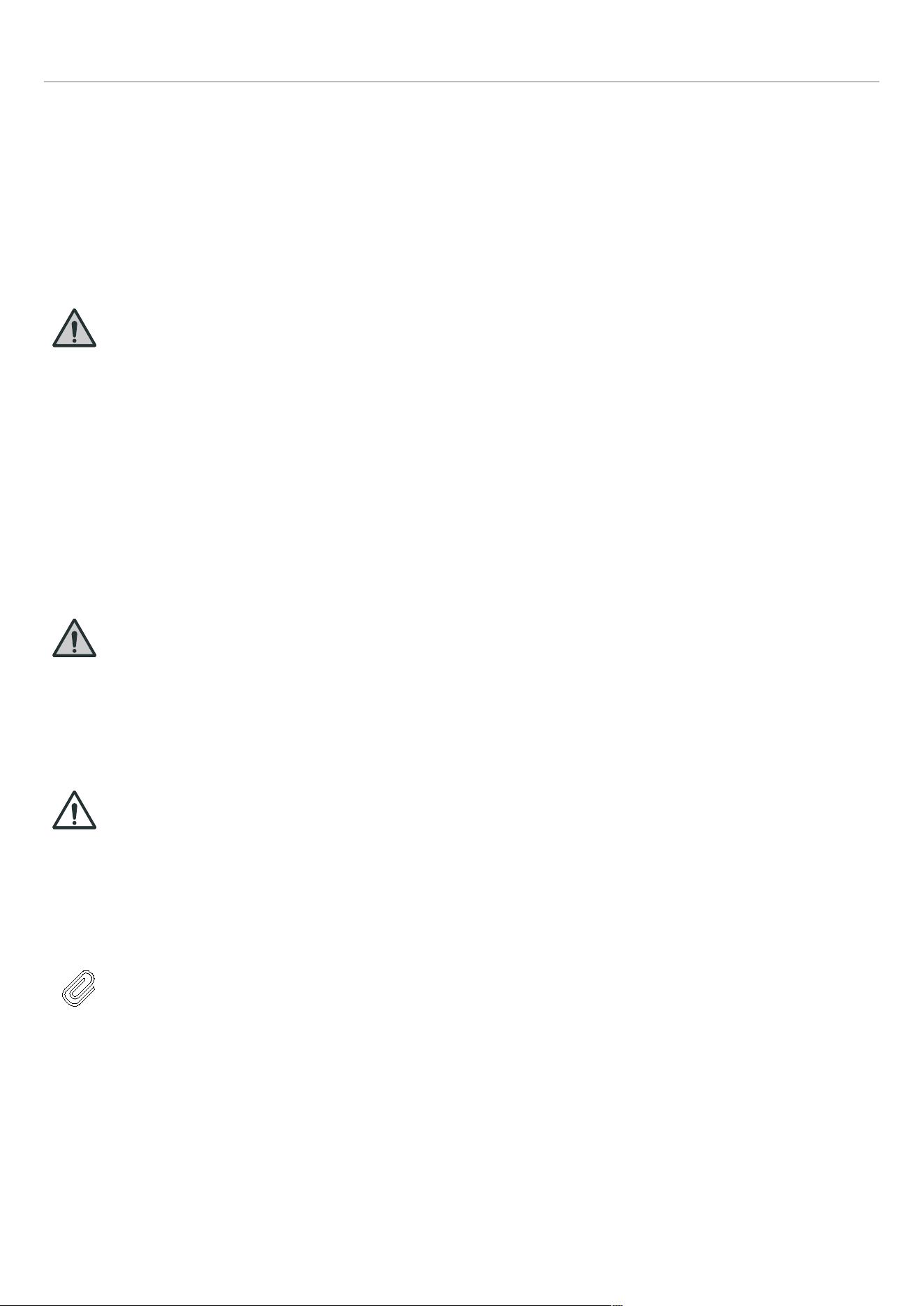
INFORMATIONS GÉNÉRALES
PRENDRE SOIN DE L’ENVIRONNEMENT
Conformez-vous scrupuleusement aux procédures
d’élimination correctes pour tous les matériaux
d’emballage. Avant la mise au rebut :
• Débrancher l’alimentation principale.
• Débrancher l’appareil et couper le cordon d’alimentation.
• Éviter d’endommager le circuit de réfrigération lors de la
mise au rebut.
MISE EN GARDE
Veiller à rendre les appareils anciens et
usés inutilisables avant leur mise au rebut
en retirant la prise, en coupant le cordon
d’alimentation et en retirant ou en
détruisant les agrafes ou les mousquetons
à boulons. Cela évitera que les enfants ne
s’enferment dans l’appareil pendant qu’ils
jouent (risque d’étouffement) ou ne mettent
leur vie en danger de toute autre manière.
Pour protéger l’environnement, il est essentiel de jeter
correctement l’emballage de votre appareil. Cela concerne
aussi bien votre ancien appareil que votre nouvel appareil
une fois qu’il a atteint la fin de sa durée de vie.
MISE EN GARDE
Risque d’incendie ou d’explosion
Avant de jeter votre ancien réfrigérateur ou
congélateur, retirer les portes. Laisser les
clayettes en place pour éviter que les
enfants ne pénètrent facilement à l’intérieur
de l’appareil.
ATTENTION !
Risque d’incendie ou d’explosion
Éliminer le réfrigérateur conformément aux
réglementations fédérales et locales en
vigueur, car il contient un réfrigérant
inflammable.
NOTE
Ne pas jeter cet appareil avec les ordures
ménagères.
Faire attention à ne pas endommager le circuit de
refroidissement, en particulier l’échangeur de chaleur situé
à l’arrière ou au bas de l’appareil.
Le symbole sur le produit ou son emballage indique que cet
appareil ne doit pas être traité comme un déchet ménager
normal, mais doit être déposé dans un point de collecte de
recyclage désigné pour les produits électriques et
électroniques. En mettant ce produit au rebut correctement,
vous contribuez à protéger l’environnement. Une mauvaise
mise au rebut peut présenter des risques pour la santé et
l’environnement.
Pour plus d’informations sur le recyclage, veuillez contacter
votre service local de collecte des déchets ou votre mairie.
ÉCONOMIE D’ÉNERGIE
Pour une économie d’énergie optimale, nous
recommandons ce qui suit :
• Installer l’appareil loin des sources de chaleur, à l’abri de
la lumière directe du soleil et dans une pièce bien aérée.
• Ne pas remplir trop les compartiments, car cela
empêche l’air de circuler correctement.
• En cas de panne d’électricité, il est conseillé de garder la
porte du réfrigérateur fermée.
• Ouvrir les portes de l’appareil le moins souvent et le
moins longtemps possible.
• S’assurer que l’unité est correctement ventilée. Ne
jamais couvrir les grilles d’aération.
• Ne jamais couvrir les étagères avec du papier aluminium
ou tout autre matériau susceptible d’empêcher la
circulation de l’air.
• Si l’appareil reste vide pendant une longue période, il est
conseillé de le débrancher et, après un nettoyage
approfondi, de laisser la porte entrouverte pour
permettre à l’air de circuler à l’intérieur du meuble afin
d’éviter la formation de condensation, de moisissures ou
d’odeurs.
DÉPLACEMENT DE L’APPAREIL
Si vous devez déplacer votre appareil, prenez les
précautions suivantes :
• Retirer tous les éléments de l’appareil.
• Fixer solidement tous les éléments amovibles (par
exemple, les étagères) à l’intérieur de l’appareil avec du
ruban adhésif.
• Tourner les pieds réglables à la base dans le sens des
aiguilles d’une montre jusqu’à ce qu’ils soient
complètement relevés pour éviter de les endommager.
• Fermer la porte avec du ruban adhésif.
• Veiller à ce que l’appareil reste en position verticale
pendant le transport.
• Protéger la porte extérieure en verre avec une
couverture ou un objet similaire pendant le transport.
64
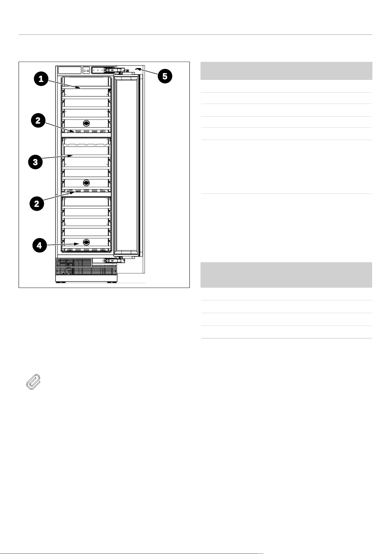
SPÉCIFICATIONS
ASPECT GÉNÉRAL
Fig. 1
1) Étagère à vin A
2) Panneau de
contrôle et paroi de
compartiment
3) Étagère à vin B
4) Filtre à charbon
5) Interrupteur
électromagnétique
NOTE
Les illustrations de ce manuel d’utilisation
sont schématiques et peuvent ne pas
correspondre exactement au produit. Si
votre produit ne dispose pas des pièces
correspondantes, les informations
s’appliquent à d’autres modèles.
CARACTÉRISTIQUES TECHNIQUES
ÉLÉMENT
DESCRIPTION
Type de connecteur NEMA 5-15P
Tension 115 V
Fréquence 60 Hz
Fusible 10 A
Intensité de courant 1,5 A
Capacité
68 bouteilles de Bordeaux
pour colonne à vin de 45
cm (18″)
100 bouteilles de Bordeaux
pour colonne à vin de
60 cm (24″)
Le réfrigérant, le volume et d’autres spécifications
techniques sont indiqués sur la plaque signalétique.
TEMPÉRATURE AMBIANTE
La température ambiante autorisée dépend de la classe
climatique :
CLASSE CLIMATIQUE
TEMPÉRATURE
AMBIANTE AUTORISÉE
SN (Subnormal) + 50 ℉ à + 87 ℉
N (Normal) + 61 ℉ à + 87 ℉
ST (Sub Tropical) + 61 ℉ à + 100 ℉
T (Tropicale) + 61 ℉ à + 109 ℉
2
5
3
1
4
2
65

INSTRUCTIONS D’INSTALLATION
PRÉPARATION POUR L’INSTALLATION
Cet appareil ne doit pas être installé à proximité de
sources de chaleur, par ex. des éléments chauffants ou
des cuisinières, ou dans un endroit humide.
Demandez l’aide d’une ou de deux autres personnes
lors de l’installation de cet appareil. Ce dernier peut
avoir des arêtes vives. Portez un EPI adapté à la tâche
et à l’environnement.
• Utilisez les pieds réglables en hauteur à l’avant de
l’appareil pour vous assurer que l’appareil est de niveau.
• Le système de refroidissement à l’arrière de l’appareil ne
doit pas toucher la paroi arrière. Plus l’écart est grand,
mieux c’est.
• L’appareil doit être installé avec une ventilation
adéquate. Assurez-vous d’avoir un dégagement au-
dessus de l’appareil afin de permettre à l’air de
s’échapper et qu’il y ait un espace entre l’arrière de
l’appareil et le mur.
Brancher l’appareil à une prise électrique exclusive et
facilement accessible.
Toute question concernant l’alimentation et/ou le
raccordement électrique doit être adressée à un électricien
qualifié ou à un centre de service après-vente agréé.
66
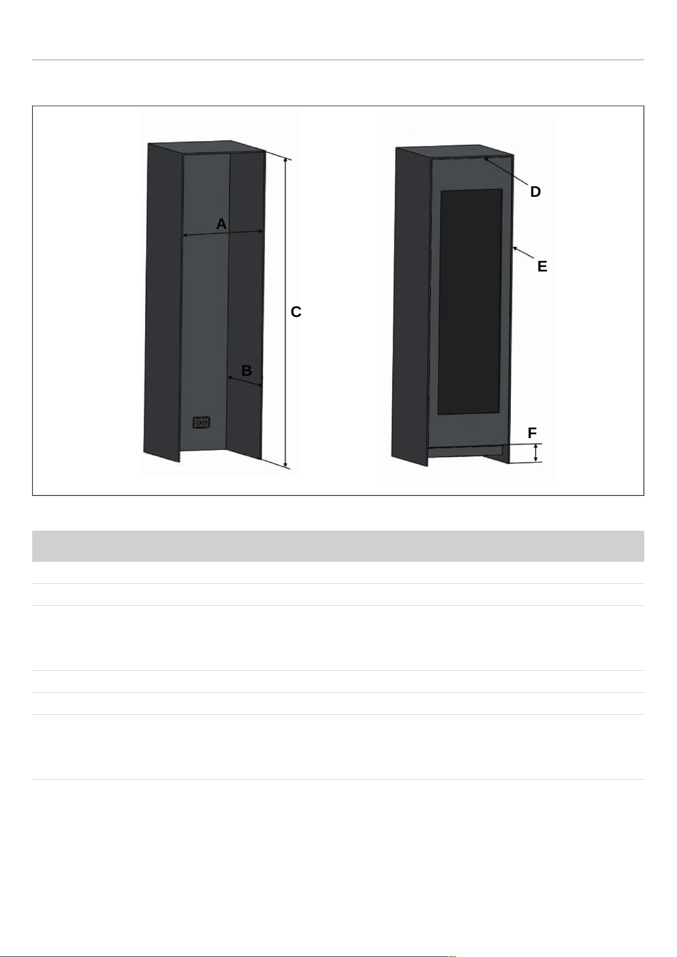
INSTRUCTIONS D’INSTALLATION
DIMENSIONS DU MEUBLE
Fig. 2
CATÉGORIE
REF18WCBPRV / REF18WCBPLV REF24WCBPNV
A
18″ (457 mm) 24″ (609 mm)
B
25″ (635 mm) 25″ (635 mm)
C
de série 84″ (2 134 mm)
minimum 83 3/4″ (2 127 mm)
maximum 85 5/16″ (2 167 mm)
de série 84″ (2 134 mm)
minimum 83 3/4″ (2 127 mm)
maximum 85 5/16″ (2 167 mm)
D
1/8″ (3 mm) 1/8″ (3 mm)
E
1/8″ (3 mm) 1/8″ (3 mm)
F
de série 4″ (101 mm)
Minimum 3 3/4″ (95 mm)
Maximum 5 5/16″ (135 mm)
de série 4″ (101 mm)
Minimum 3 3/4″ (95 mm)
Maximum 5 5/16″ (135 mm)
D
E
F
A
B
C
67

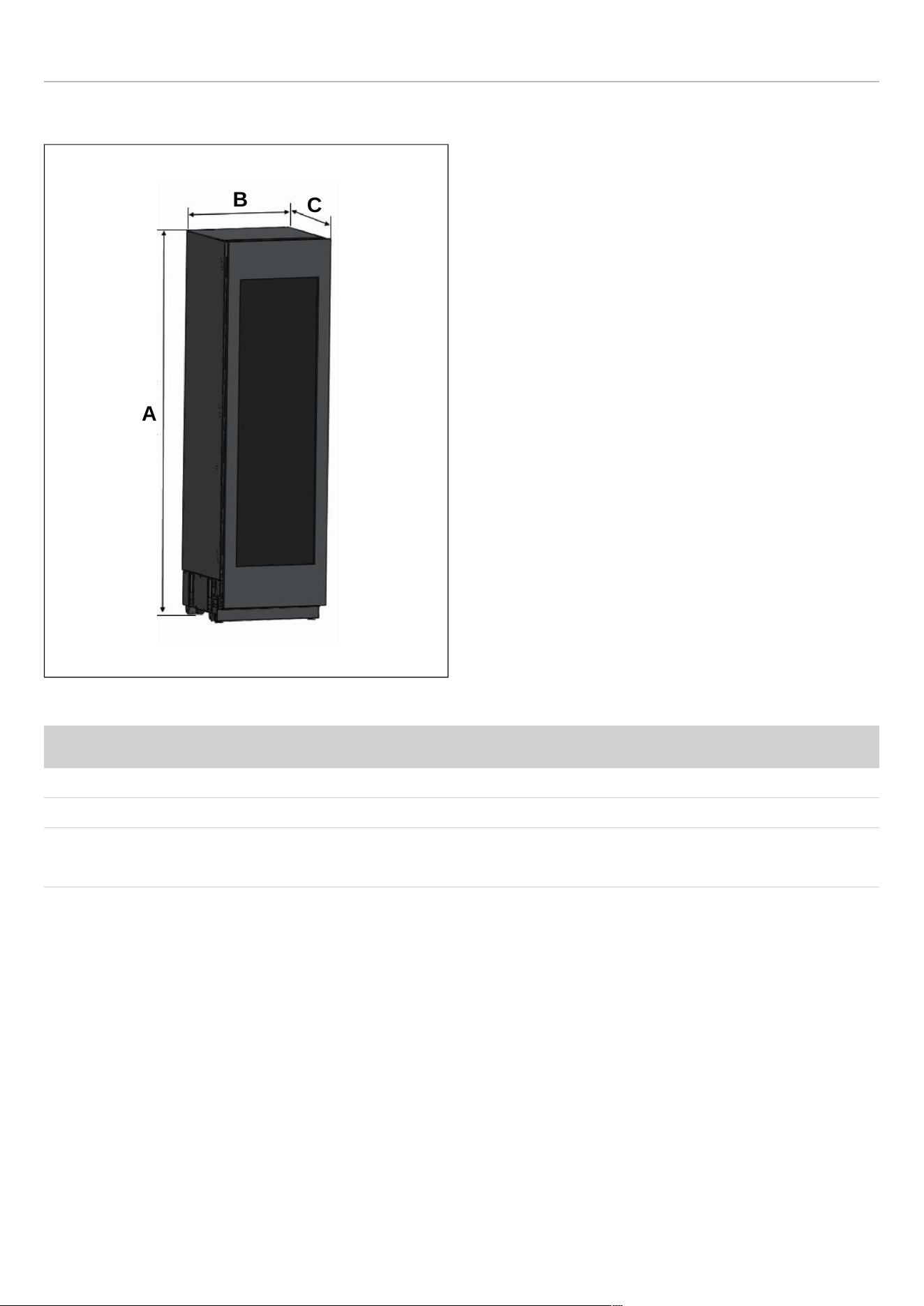

INSTRUCTIONS D’INSTALLATION
PANNEAU DE PORTE PERSONNALISÉ
Fig. 5
CATÉGORIE
REF18WCBPRV / REF18WCBPLV REF24WCBPNV
A
79 15/16″ (2030 mm) 79 15/16″ (2030 mm)
B
3/4″ - 1 1/2″ (19-38 mm) épaisseur 3/4″ - 1 1/2″ (19-38 mm) épaisseur
C
17 3/4″ (451 mm) 23 3/4″ (603 mm)
D
12 1/4″ (311 mm) 18 1/4″ (463 mm)
E
2 3/4″ (70 mm) 2 3/4″ (70 mm)
F
9 1/16″ (230 mm) 9 1/16″ (230 mm)
Poids maximal du panneau de porte personnalisé : 66 lbs (30 kg)
A
B
C
D
E
F
F
70
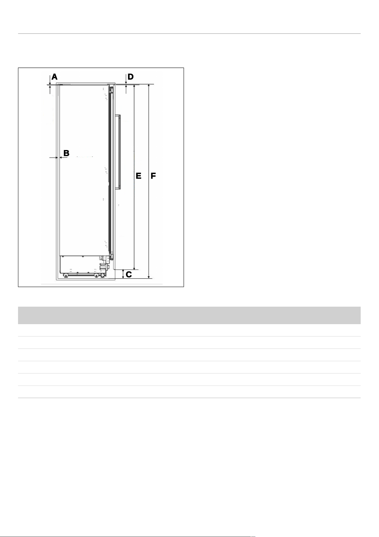
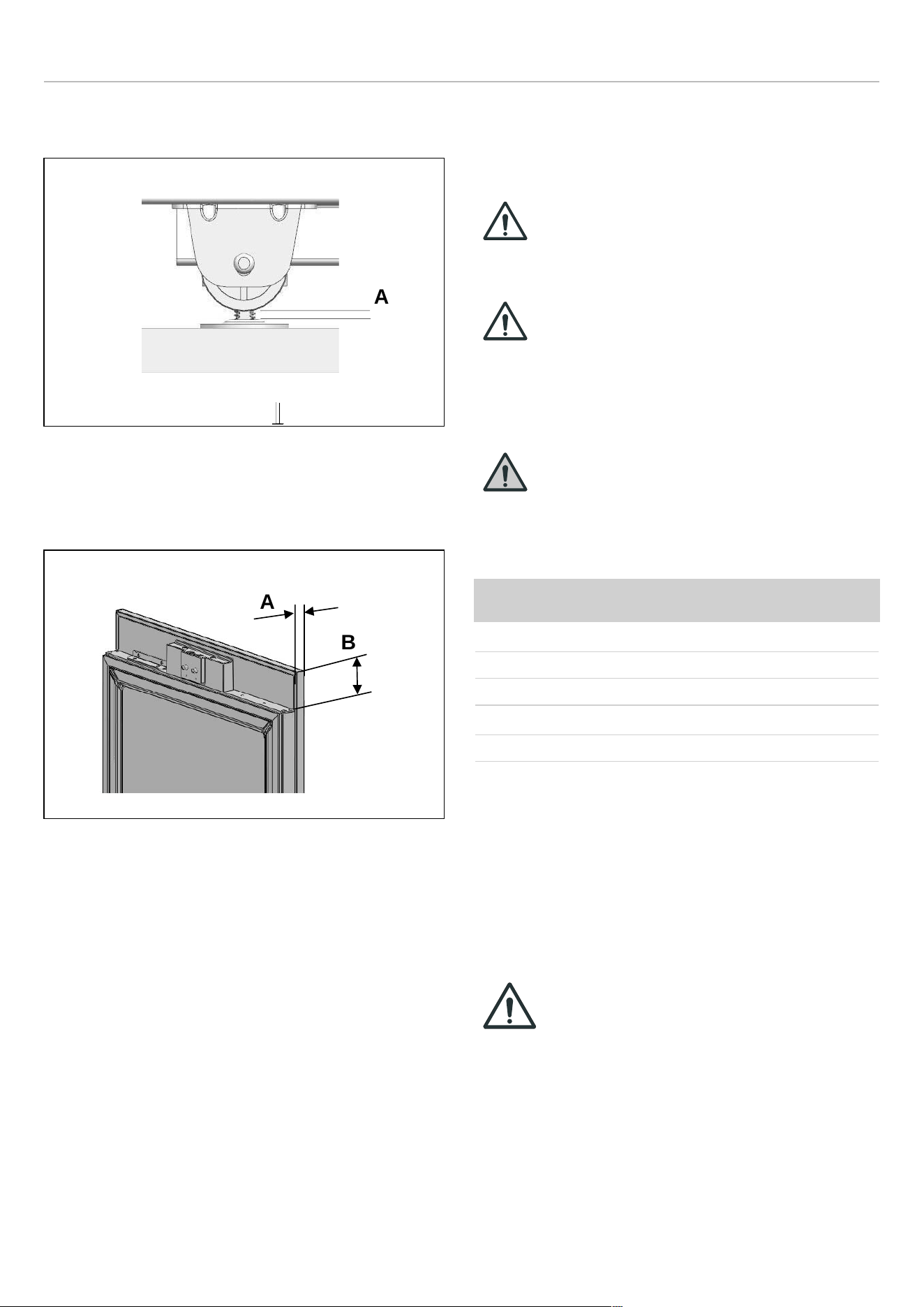
INSTRUCTIONS D’INSTALLATION
RÉGLAGE MINIMUM DE LA HAUTEUR POUR LA MISE
À NIVEAU
Fig. 7
A. 5/16″ (8 mm)
DIMENSION D’ASSEMBLAGE ENTRE LE PANNEAU EN
BOIS ET LA PORTE DU RÉFRIGÉRATEUR
Fig. 8
A. 3/4″ (19 mm)
B. 3 3/8″ (82 mm)
EXIGENCES ÉLECTRIQUES
L’appareil doit être installé sur tous les raccordements
électriques conformément aux codes nationaux et locaux.
ATTENTION !
Ne pas utiliser de rallonges ou
d’adaptateurs à deux broches, ni retirer la
borne de terre du câble de mise à la terre.
ATTENTION !
Un électricien qualifié doit s’assurer que les
pôles de la prise sont correctement
branchés.
Vérifiez que la mise à la terre de la prise est
correcte.
MISE EN GARDE
Ne pas brancher l’appareil sur des prises à
économie d’énergie électroniques.
La prise doit être conforme aux données suivantes :
EXIGENCES ÉLECTRIQUES
Type de connecteur NEMA 5-15P
Sortie
3 broches
Tension 115 V
Fréquence 60 Hz
Fusible 10 A
L’appareil doit être branché sur sa propre prise électrique
individuelle avec une tension nominale correspondant à
celle indiquée sur l’étiquette signalétique de l’appareil. Cela
permet d’obtenir les meilleures performances et d’éviter
ainsi de surcharger les circuits de câblage qui pourraient
provoquer un risque d’incendie dû à une surchauffe.
REMARQUE IMPORTANTE
Ne pas utiliser de rallonges et/ou
d’adaptateurs multiples pour le
raccordement au réseau électrique.
Si le câblage électrique ou l’alimentation électrique de
l’habitation nécessite une modification, les procédures
nécessaires doivent être effectuées par un électricien
qualifié.
Veuillez respecter les règles suivantes :
A
A
B
72
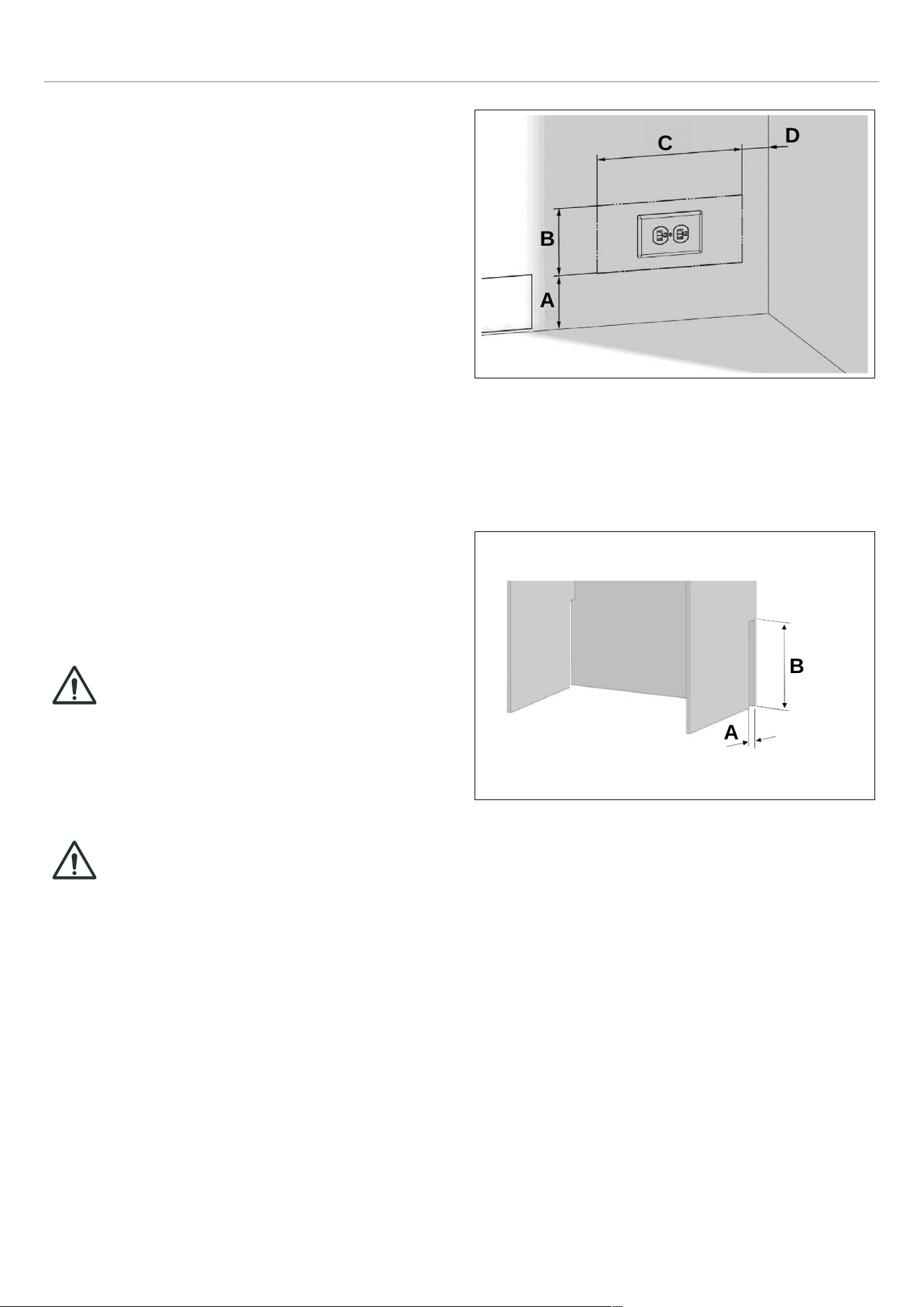
INSTRUCTIONS D’INSTALLATION
• La prise ou le tableau électrique doit être facilement
accessible en cas d’urgence, et ne doit pas être
dissimulé derrière le produit.
• Ni la fiche ni le câble ne doivent toucher la surface
arrière de l’appareil, sous peine d'être endommagés par
les vibrations de l’appareil.
• Pour éviter toute blessure accidentelle, le cordon doit
être fixé derrière l’appareil et non exposé ou suspendu.
• Ne pas brancher des fiches d’autres équipements
derrière cet appareil. Si l’appareil est utilisé dans une
pièce où le taux d’humidité est élevé, ses surfaces
extérieures peuvent se corroder. Pour éviter la
corrosion, veillez à maintenir la pièce sèche et bien
propre.
Pour prévenir le risque de choc électrique :
• Connecter la fiche à une prise de terre.
• Ne pas retirer la broche de mise à la terre de la fiche.
• Ne pas utiliser d’adaptateurs.
• Ne pas utiliser de rallonges électriques à moins que le
cordon n’ait été vérifié et testé par un technicien ou un
technicien qualifié. La rallonge électrique doit être
homologuée UL/CUL, à 3 fils, avec mise à la terre, dotée
d’une fiche et d’une prise de terre et dont la puissance
nominale électrique est de 115 volts et d’au moins
10 ampères.
• Ne jamais débrancher l’appareil en tirant sur le cordon
d’alimentation.
ATTENTION !
Ne pas connecter le câble de mise à la
terre à la conduite de gaz. Veuillez faire
vérifier la mise à la terre par un électricien
qualifié si vous n’êtes pas sûr de la mise à
la terre de l’appareil. Ne pas installer de
fusible sur la ligne neutre ou sur le circuit
de mise à la terre.
ATTENTION !
Le non-respect de ces instructions peut
entraîner un incendie, un choc électrique
ou la mort. La connexion du conducteur de
mise à la terre de l’appareil au mauvais
endroit peut entraîner un choc électrique.
Veuillez faire vérifier la mise à la terre par
un électricien qualifié ou un technicien de
service si vous avez des doutes sur la mise
à la terre correcte de l’appareil.
L’installation, les réparations et autres
interventions effectuées par des personnes
non qualifiées peuvent donner lieu à des
dangers. Avant d’installer l’appareil,
assurez-vous que les paramètres de
tension, de charge et de courant du circuit
sur la plaque signalétique sont conformes à
l’alimentation électrique de votre habitation.
Fig. 9
• A 4″ (102 mm)
• B 5″ (127 mm)
• C 11″ (280 mm)
• D 2″ (50.8 mm)
Fig. 10
• A 2″ (50.8 mm)
• B 8″ (203,2 mm)
A
B
C
D
A
B
73
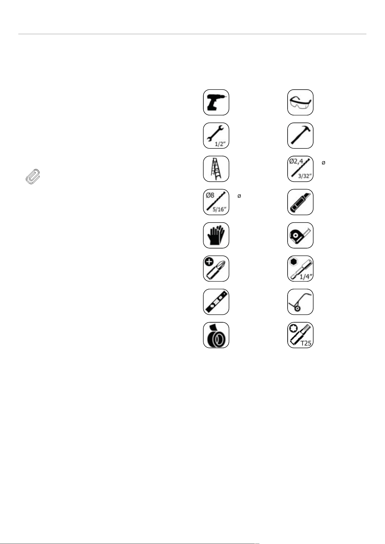
INSTRUCTIONS D’INSTALLATION
VENTILATION
La chaleur retirée du compartiment de refroidissement doit
être dissipée dans l’air autour de l’appareil. Une ventilation
incorrecte peut entraîner une panne prématurée du
compresseur, une consommation électrique excessive et
une panne totale du système, et peut annuler la garantie
fournie avec l’appareil.
Une grille de ventilation d’air est présente à la base de
l’appareil.
Le dégagement à l’arrière de l’appareil est clairement
indiqué.
NOTE
La grille d’aération située à l’avant de
l’appareil ne doit jamais être recouverte ou
obstruée de quelque façon que ce soit.
LISTE DES OUTILS
Les outils à utiliser lors de l’installation du produit sont les
suivants :
Perceuse
sans fil
Lunettes de
sécurité
Clé de
12,7 mm (1/
2″)
Marteau
Échelle
Foret
2,4 mm
Foret
8,0 mm
Cutter
Gants de
sécurité
Mètre ruban
Mèche à tête
cruciforme
Embout
hexagonal de
6,4 mm (1/4″)
Niveau à bulle
Diable chariot
pour appareils
électroména-
gers
Ruban
Embouts Torx
T25
74
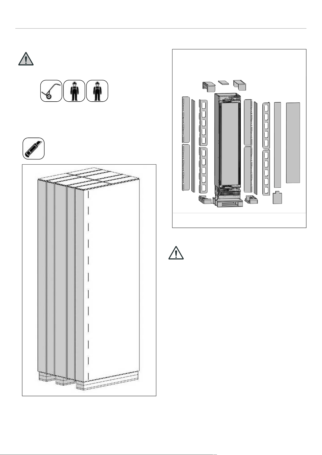
INSTRUCTIONS D’INSTALLATION
DÉBALLAGE
MISE EN GARDE
Deux personnes au moins sont
nécessaires pour transporter le
réfrigérateur.
• Éliminez le ruban adhésif à l’aide d’un cutter.
• Coupez l’emballage en carton le long des lignes
pointillées à l’aide d’un cutter, puis retirez-le.
Fig. 11
• Éliminez les matériaux d’emballage en polystyrène.
Fig. 12
ATTENTION !
Ne retirez pas le ruban adhésif de la porte
supérieure de l’appareil tant que le
réfrigérateur n’est pas placé dans l’armoire.
Risque de basculement.
75
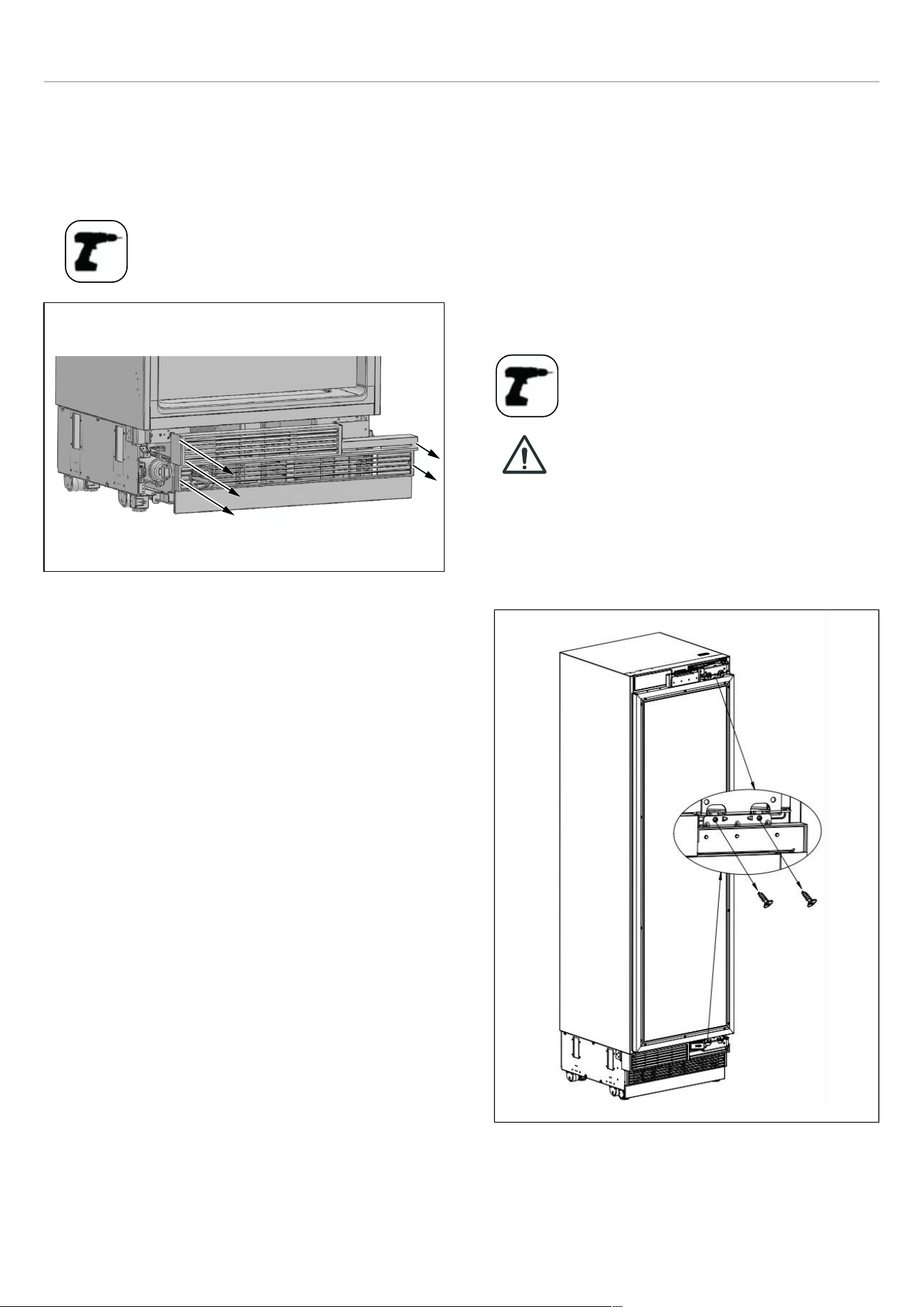
INSTRUCTIONS D’INSTALLATION
RETRAIT DE L’ENSEMBLE ÉVENTS
D’AÉRATION
• Déposez les 5 vis pour dégager l’ensemble évents
d’aération.
Fig. 13
INVERSION DU BATTEMENT DE LA PORTE
(LE CAS ÉCHÉANT)
Nous vous recommandons de demander l’aide d’une
autre personne pour soutenir les portes pendant que
vous effectuez cette opération.
L’ouverture de l’armoire à vin peut être inversée selon la
position d’installation. Si nécessaire, faites-le avant de
placer la cave à vin dans l’armoire.
• Retirez les vis de connexion de la charnière des
supports de charnière.
ATTENTION !
La porte se détachera lorsque ces vis
auront été retirées. Il est nécessaire de
veiller à ce que la porte ne tombe pas.
Pour ce faire, collez la porte de l’armoire
à la porte intérieure à l’aide de ruban
adhésif ou demandez à une deuxième
personne de vous aider.
Fig. 14
• Retirez la porte et la poser sur une table.
76
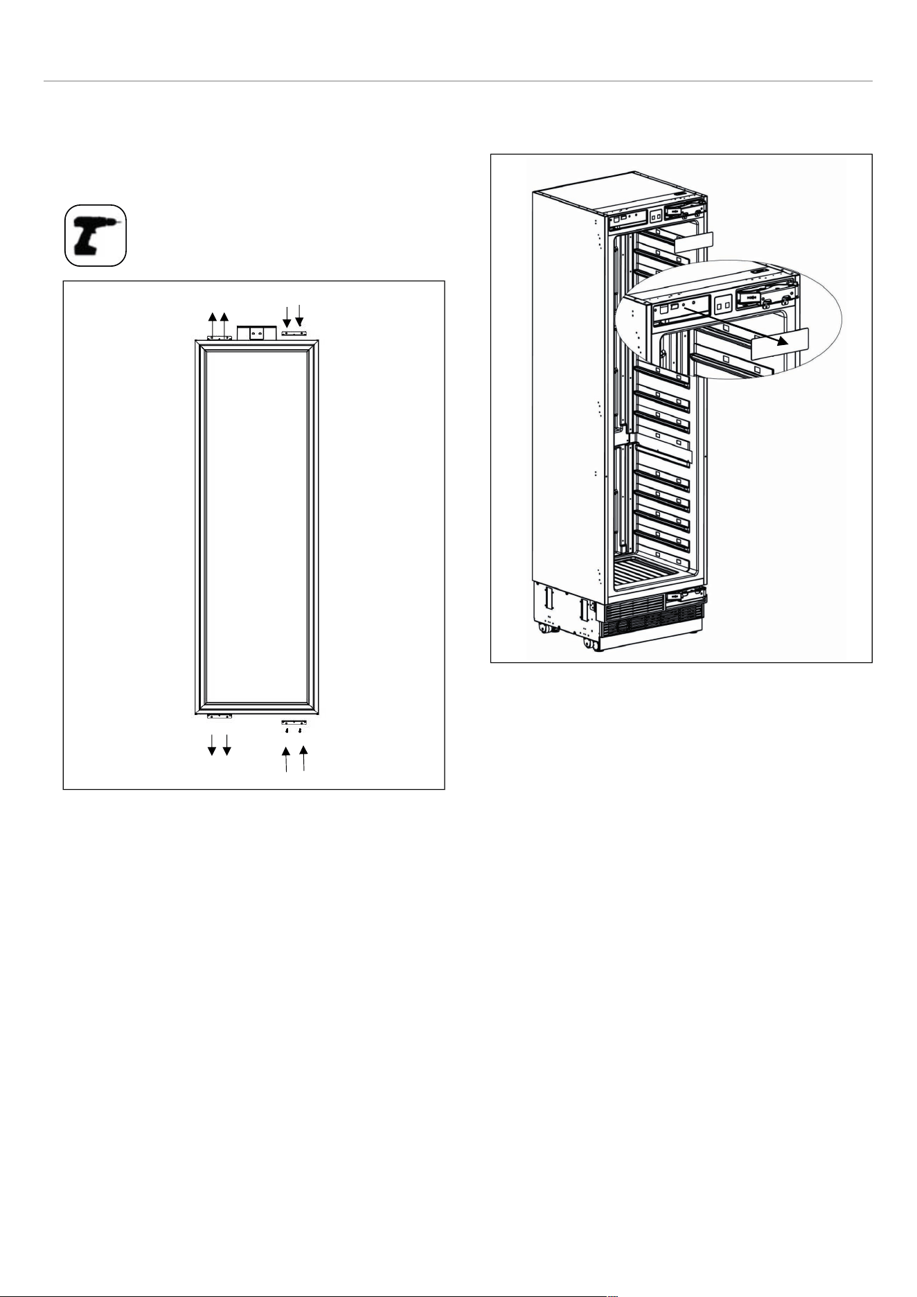
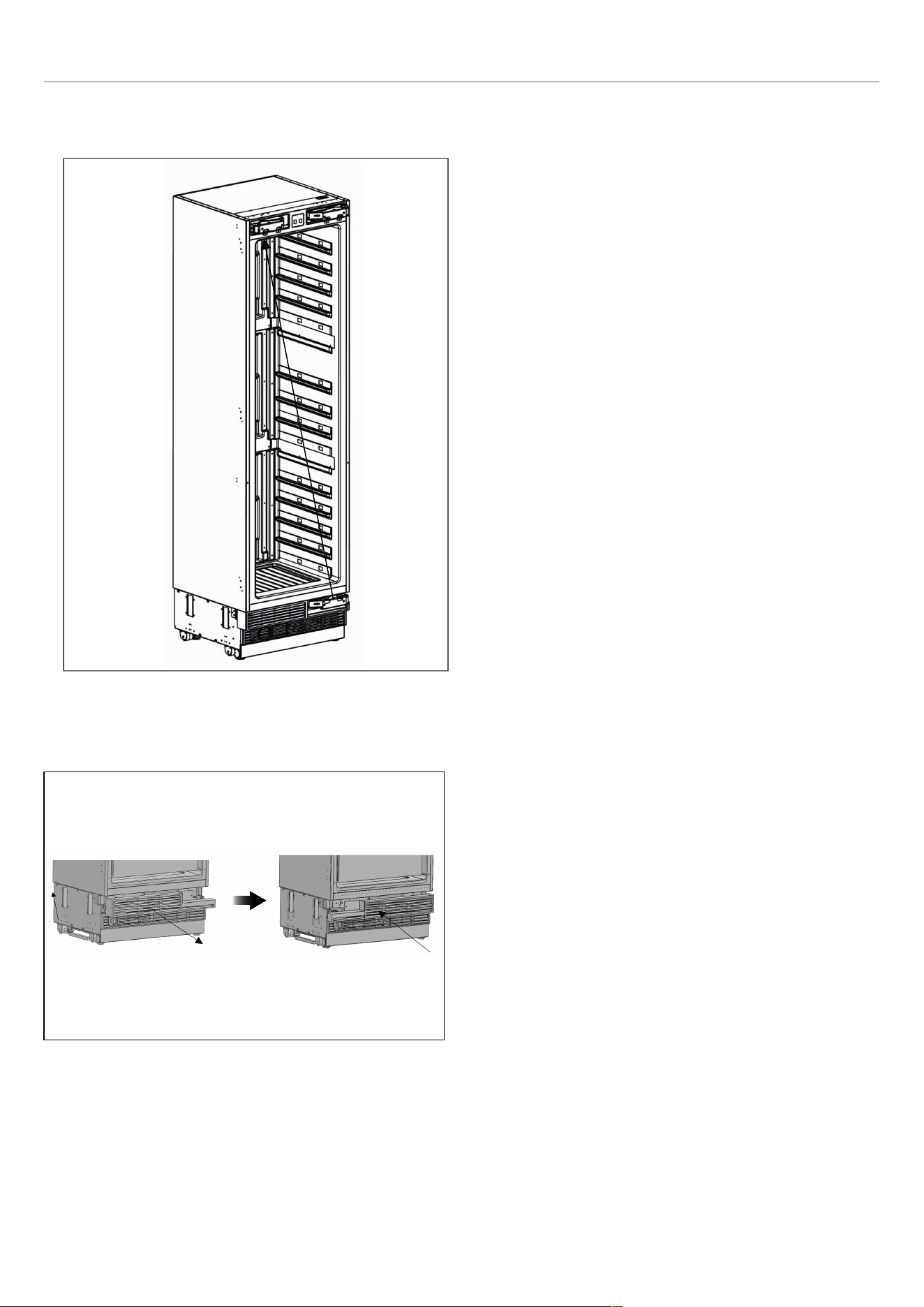
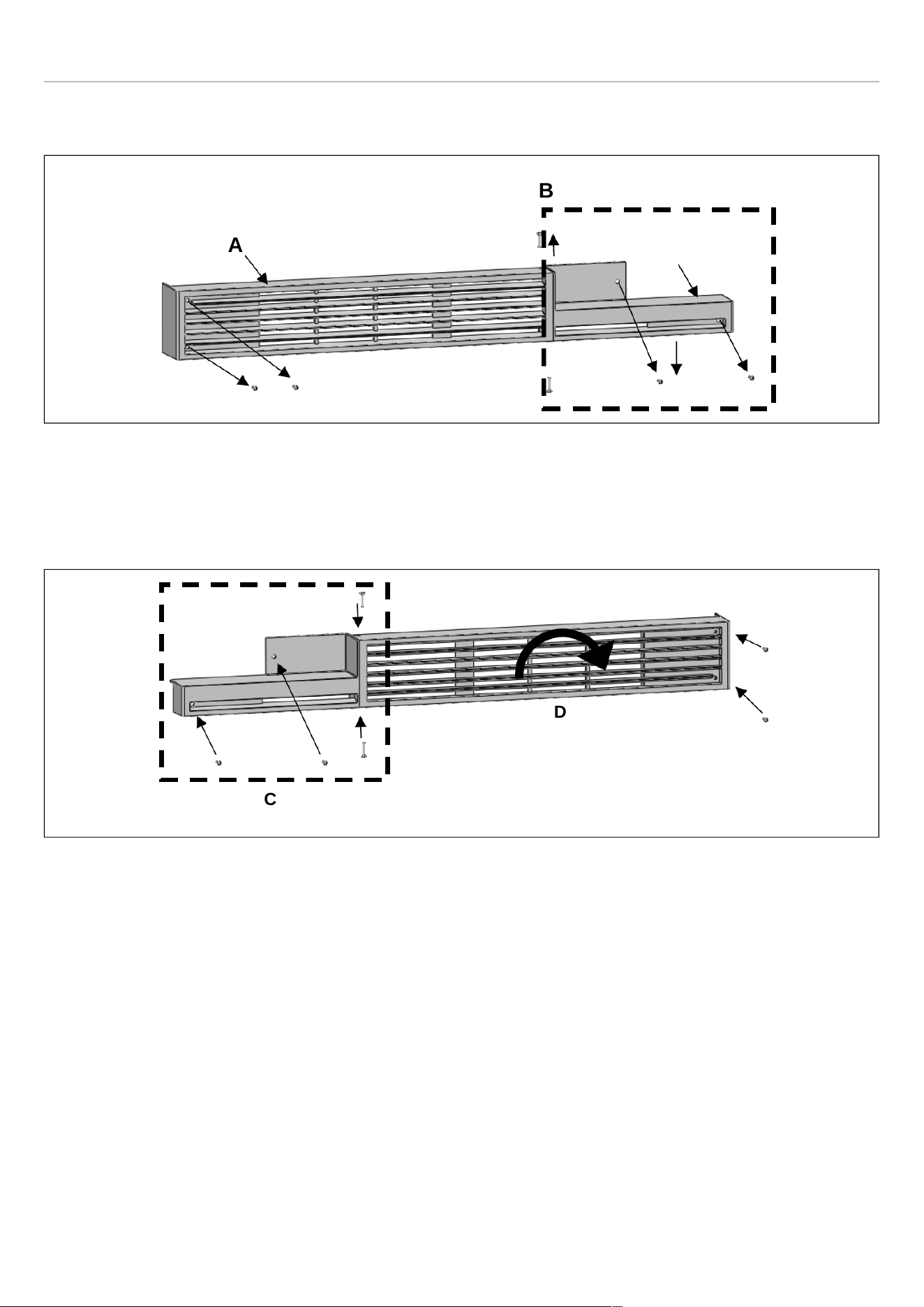
INSTRUCTIONS D’INSTALLATION
• Partie supérieure de l’évent d’aération pour la charnière
droite
Fig. 19
• A Couvercle évent d’aération
• B Élément charnière évent d’aération de droite
• Partie supérieure de l’évent d’aération pour la charnière
gauche
Fig. 20
• C Élément charnière évent d’aération de gauche
• D Faire pivoter couvercle évent d’aération de 180°°
A
B
C
D
79
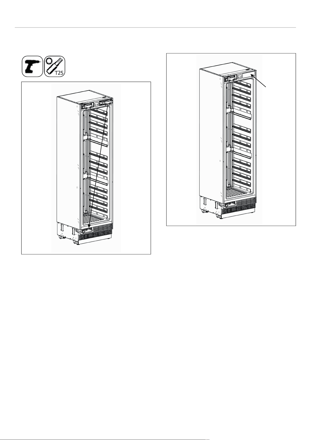
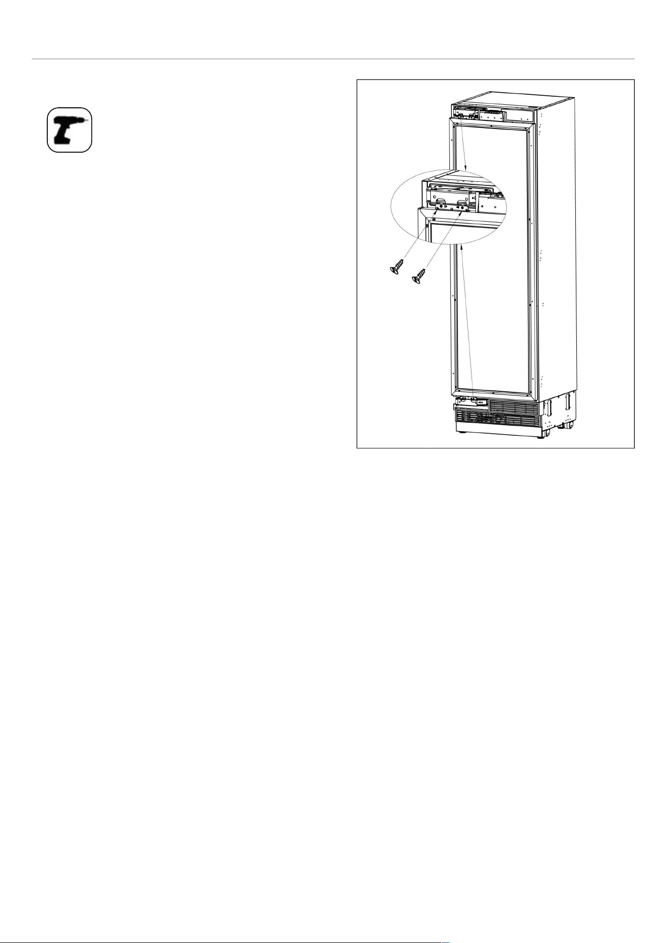

INSTRUCTIONS D’INSTALLATION
INSTRUCTION D’INSTALLATION (PORTE SUR CHARNIÈRE DE PORTE)
DESCRIPTION
REF18WCBPRV /
REF18WCBPLV
REF24WCBPNV
Poignée de porte (le cas échéant)
1 1
Clé Allen/hexagonale (le cas échéant)
1 1
Fixation de montage de poignée
(le cas échéant)
2 2
Joint (le cas échéant)
2 2
Écrou d’arrêt, M5 (le cas échéant)
2 2
vis de réglage, M5*10 (le cas échéant)
2 2
Bride anti-basculement
2 2
Vis et chevilles bride anti basculement
8 8
Équerre d’assemblage meuble
8 8
Vis à tête fraisée, ST4x14
20 20
Tête de rondelle Truss, ST4*12
16 16
Pièce de réglage de position
1 1
Vis à tête fraisée pour fixation de portes en
bois ST4x35
8 8
Pièce de charnière de ventilation (le cas
échéant)
\ 1
Goupille de butée 90°
2 2
Gabarit de préparation de porte de meuble
1 1
pièces décoratives
1+2+2 1+2+2
Manuel d’utilisation
1 1
82
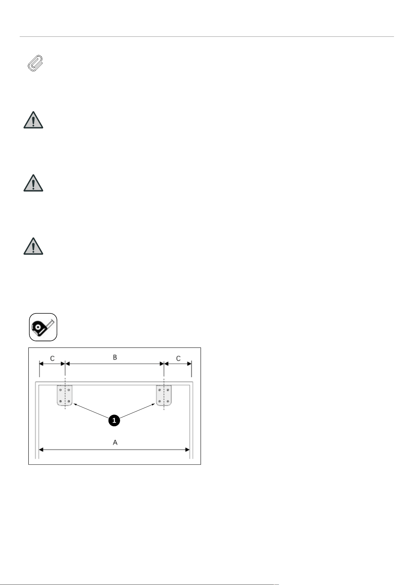
INSTRUCTIONS D’INSTALLATION
NOTE
L’appareil doit être branché avant l’installation.
MONTAGE DES SUPPORTS ANTI-
BASCULEMENT
MISE EN GARDE
Si l’appareil ne peut pas être fixé à
l’armoire (qui doit à son tour être fixée au
mur), assurez-vous d’utiliser les brides anti-
basculement fournies pour éviter tout
basculement du produit.
MISE EN GARDE
Vérifiez qu’il n’y a pas de connexion
électrique ou d’eau dans les armoires
adjacentes dans lesquelles les vis de
montage seront vissées pour fixer le
réfrigérateur.
MISE EN GARDE
Munissez-vous de l’équipement de
protection nécessaire lors du perçage de
trous dans le mur et au moment de
l’installation.
• À l’aide d’un ruban à mesurer, marquez les repères sur
la paroi pour l’installation des brides anti-basculement.
Fig. 24
• 1 Bride anti-basculement, sur la paroi
1
83

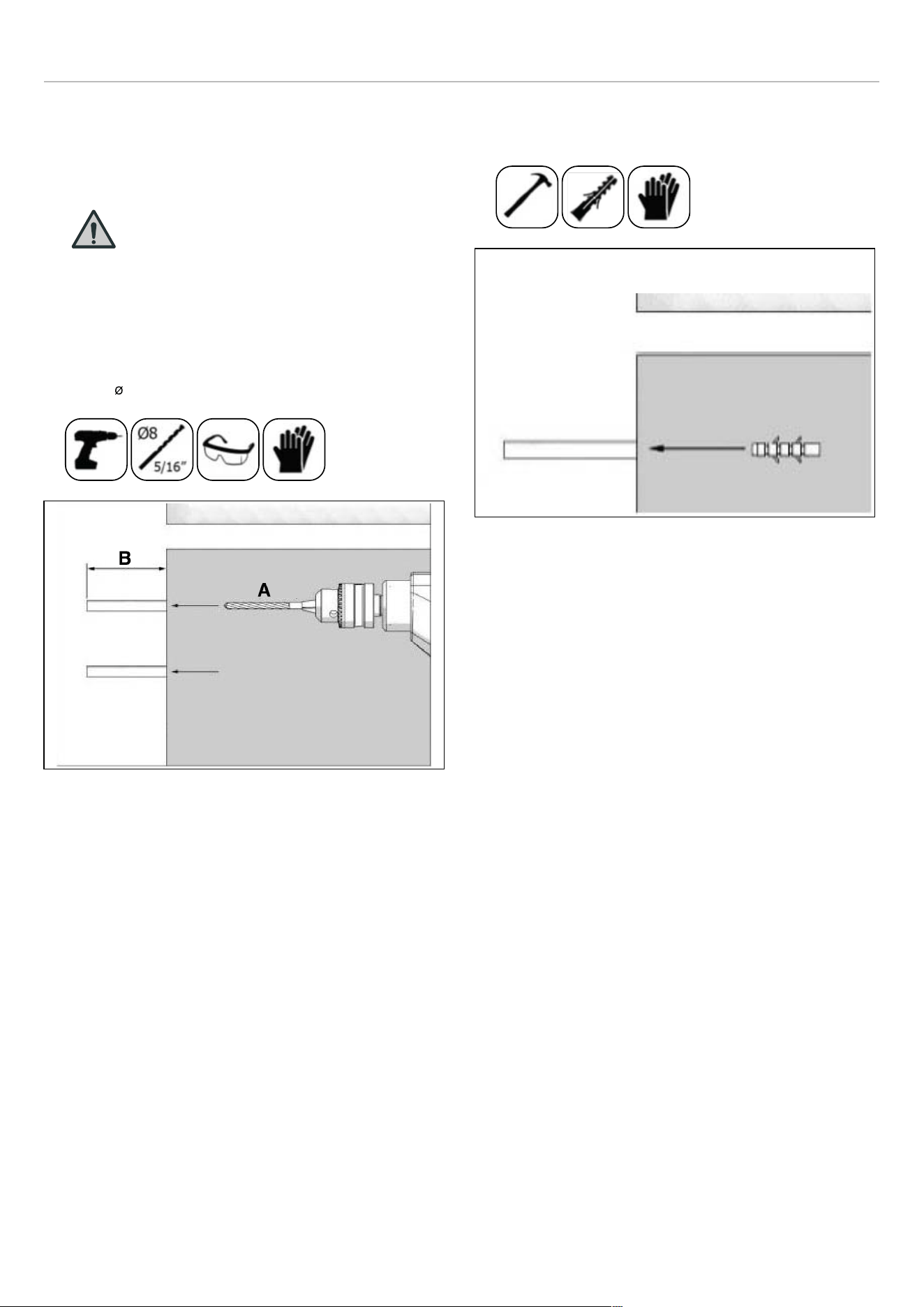
INSTRUCTIONS D’INSTALLATION
• Pour que l’installation soit la plus sûre possible, utilisez
un détecteur de montant pour fixer les brides anti-
basculement dans les montants muraux. Si aucun
montant n’est présent à l’endroit de l’installation, suivez
les instructions ci-dessous.
MISE EN GARDE
Vérifiez toujours qu’aucune conduite
d’eau et qu’aucun circuit électrique ne
sont présents dans la zone à forer sous
peine de causer des dommages
matériels, corporels, voire la mort.
• À l’aide d’une perceuse, réalisez aux points marqués les
trous destinés aux ancrages muraux (n ° 2) 7,9 mm (5/
16″ Ø), 8 mm).
Fig. 25
A. 5/16″ (Ø8 mm)
B. > 62 mm
• Installez les ancrages muraux (n ° 2) à l’aide d’un
marteau si aucun montant n’est présent.
Fig. 26
• Installez les brides (n° 1) à leur place et fixez-les à l’aide
de 4 vis.
85
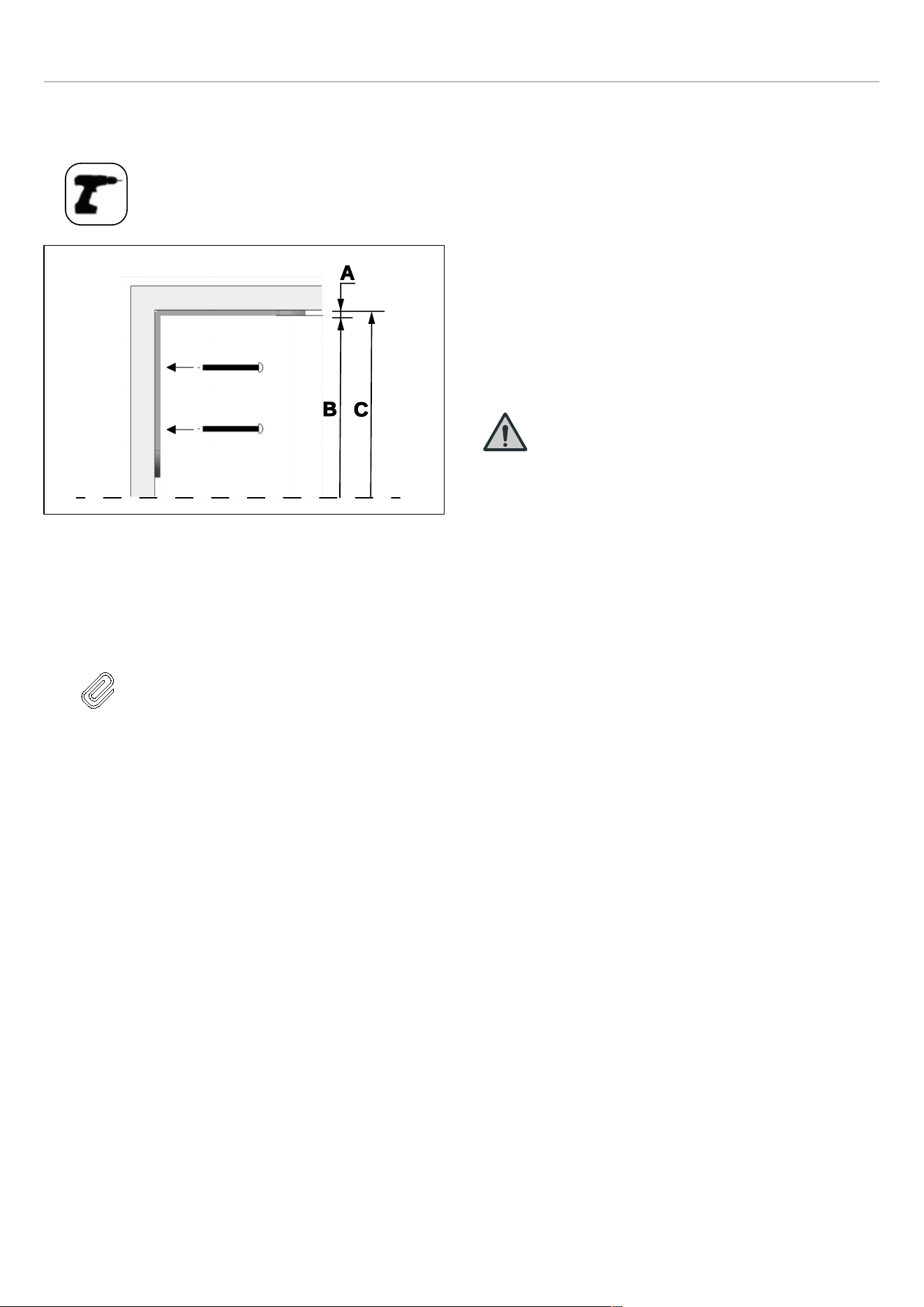
INSTRUCTIONS D’INSTALLATION
• Il est nécessaire d’utiliser deux brides pour que l’appareil
soit soutenu en toute sécurité.
Fig. 27
A. 4 mm (3/16″)
B. 83 27/32″ (2 130 mm)
C. 84″ (2 134 mm)
NOTE
Si vous n’êtes pas sûr que les
connecteurs et les brides anti-
basculement fournis sont montés au mur
de manière suffisamment solide, vous
pouvez utiliser d’autres méthodes anti-
basculement.
S’il y a un panneau d’armoire derrière la
paroi arrière du réfrigérateur, assurez-
vous qu’il est solidement fixé au mur.
Pour cela, vous devez vous assurer que
la paroi arrière du panneau d’armoire est
fixée à un montant du mur.
Méthode anti-basculement alternative :
Si les brides anti-basculement ne peuvent pas être
montées en toute sécurité, vous devez utiliser la méthode
alternative ci-dessous. Pour cette méthode, vous pouvez
utiliser des planches de bois pour éviter que l’appareil ne
bascule.
Elles doivent être installées comme illustré dans la figure
ci-dessous.
Il ne doit pas y avoir d’espace libre entre l’appareil et le
support en bois.
Les dimensions minimales de la section du support en bois
doivent être de 3″ x 4″ (76 mm x 102 mm). La largeur du
support doit être égale à l’espace où il sera installé. Cela
peut être réalisé en utilisant un morceau de bois de
charpente de 4″ x 4″ (102 mm x 102 mm) ou deux
morceaux de 2″ x 4″ (51 mm x 102 mm).
Le calcul de la profondeur de blocage est basé sur une
profondeur de niche standard. Si la profondeur de la niche
est supérieure à 24″ (610 mm), assurez-vous que le
blocage chevauche le corps supérieur arrière du
réfrigérateur de 2″ (51 mm).
Placez le support en bois, marquez l’emplacement sur la
paroi arrière, sélectionnez les vis appropriées et montez-le
solidement.
MISE EN GARDE
La quantité et le type de vis ou d’attaches à
utiliser pour fixer les blocs de bois doivent
permettre de garantir une fixation sûre à la
paroi arrière.
A
B
C
86
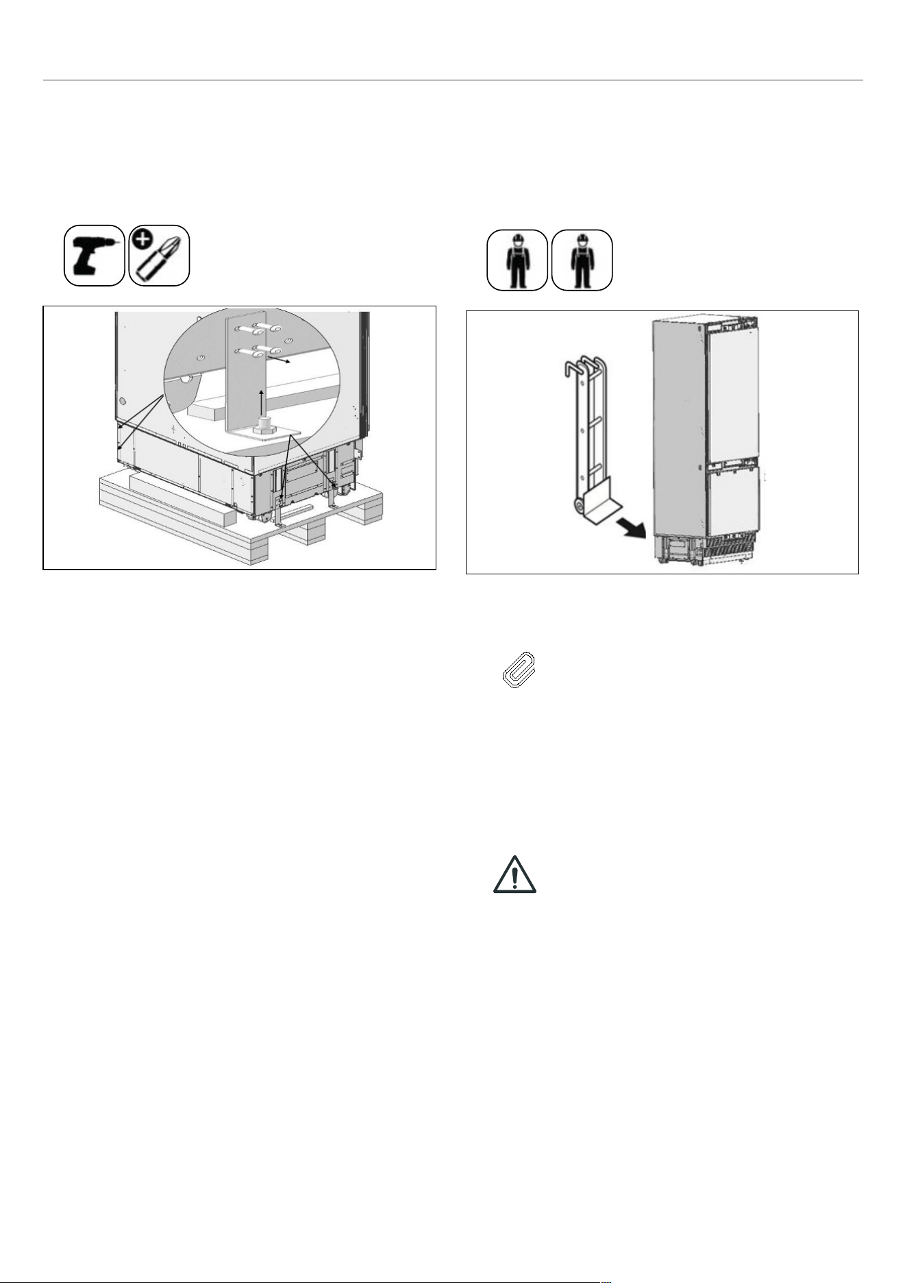
INSTRUCTIONS D’INSTALLATION
INSTALLATION DANS L’ARMOIRE
Dégagement du réfrigérateur de la palette en bois
• Retirez les supports qui fixent le réfrigérateur à la palette
en bois comme indiqué ci-dessous.
Fig. 28
• Inclinez lentement le réfrigérateur vers l’arrière et
dégagez-le de la palette, en prenant soin de ne pas
endommager le dessous de l’appareil. Lorsque vous
transportez l’appareil, maintenez-le toujours sur les
côtés pour vous assurer que les pieds de l’appareil
restent sur la base du chariot de l’appareil.
Fig. 29
NOTE
Soyez extrêmement prudent lorsque
vous manipulez l’appareil, car le
dessous du réfrigérateur contient des
composants essentiels à son bon
fonctionnement. Tout endommagement
de ces composants pourrait entraîner un
mauvais fonctionnement ou une fuite
potentielle de condensat et des
dommages aux planchers.
ATTENTION !
Le risque de basculement est élevé à
partir de ce moment-là. Vous ne devez
pas ouvrir les portes tant que le produit
n’est pas installé dans l’armoire.
87
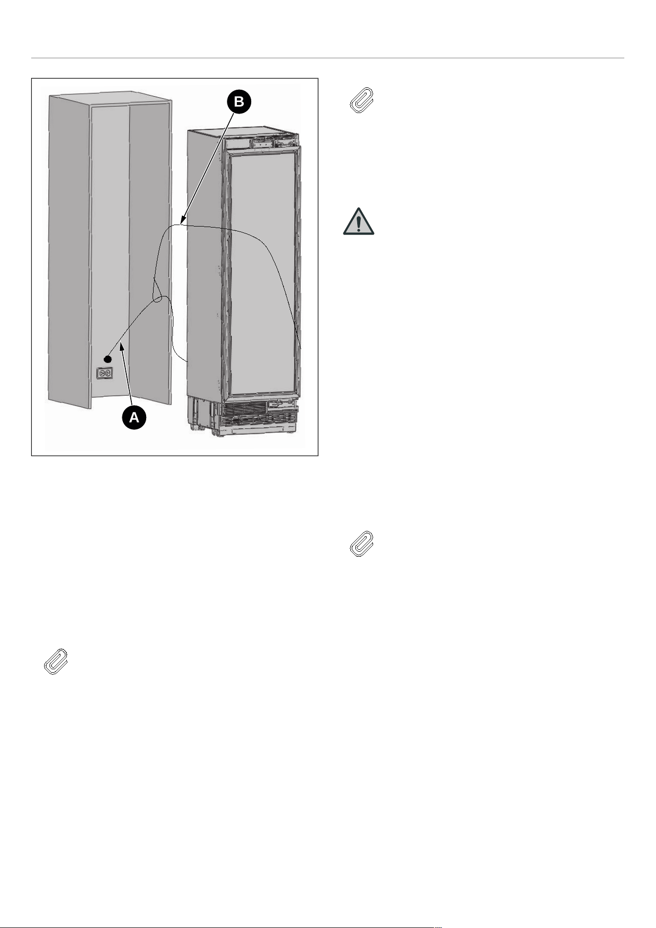
INSTRUCTIONS D’INSTALLATION
Fig. 30
• A Cordon d’alimentation
• B Cordon en Nylon
• C Déplacer vers le mur
• D Tuyau d’eau
Branchez la fiche électrique à la prise de courant. Allumez
l’appareil pour vous assurer qu’il est alimenté. (Pour voir si
le produit fonctionne, vérifiez si les lampes dans le
compartiment congélateur sont allumées ou éteintes.)
NOTE
Protégez les bords avant de la niche de
l’armoire avec du ruban adhésif. Cela
permettra de les protéger contre tout
endommagement éventuel au moment de
repousser l’appareil dans la niche. Fixez
l’excédent de cordon électrique à l’arrière
de l’appareil à l’aide de ruban adhésif, afin
d’éviter que le mou ne s’accroche sous
l’appareil pendant l’installation.
NOTE
La fiche de l’appareil doit être accessible
après l’installation. Si la fiche n’est pas
accessible après l’installation,
l’alimentation doit être dotée d’un
disjoncteur dédié accessible pour couper
l’alimentation à l’aide de l’interrupteur
principal.
MISE EN GARDE
• Assurez-vous que le cordon
d’alimentation ne se coince pas lors de
la mise en place du produit.
• Poussez délicatement le produit vers
l’armoire pour le mettre en place.
L’appareil devrait glisser dans la
niche avec une relative facilité. Si
vous ressentez une résistance en
plaçant le produit dans l’armoire :
• Le sol peut être inégal.
• Les pieds réglables peuvent être
lâches (veuillez consulter la
section correspondante pour
savoir comment ajuster les pieds
réglables).
• Vous devez fixer temporairement la
porte du congélateur pour aligner le
produit avant de le positionner.
NOTE
Utilisez les bords supérieurs des portes du
réfrigérateur et du congélateur pour aligner
l’unité dans l’ouverture de la niche.
Le réglage des autres bords est expliqué
dans les pages suivantes.
A
B
88
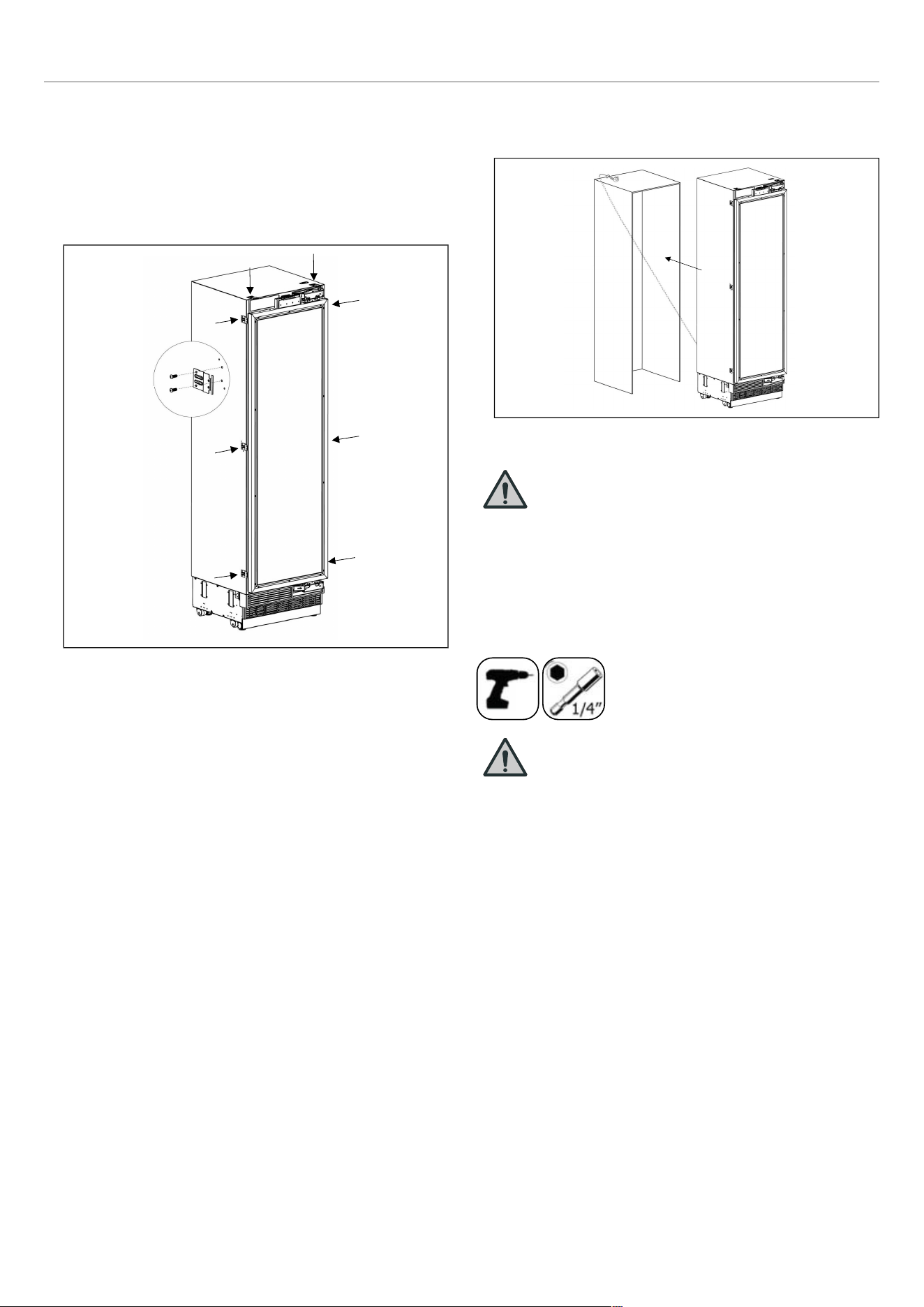
INSTRUCTIONS D’INSTALLATION
VISSAGE DES SUPPORTS LATÉRAUX ET
SUPÉRIEURS
Fixez les supports de meubles à l’unité, où 2 en haut et 3
de chaque côté.
• Utilisez les rondelle à tête Truss (M4*12) pour serrer.
Fig. 31
• Poussez soigneusement le produit vers l’armoire pour le
placer.
Fig. 32
MISE EN GARDE
La prise du produit doit être accessible
après l’installation
RÉGLAGE DE LA HAUTEUR
• Utilisez le mécanisme à jambe réglable pour soulever,
abaisser et mettre l’unité de niveau dans la niche selon
le diagramme ci-dessous.
MISE EN GARDE
Une fois que l’appareil est poussé dans la
niche, levez d’abord les pieds avant. Cela
réduira le risque de basculement vers
l’avant de l’unité pendant le processus de
réglage de la hauteur.
La hauteur maximale que les pieds
réglables peuvent atteindre est de 40 mm
(1 9/16″).
89


INSTRUCTIONS D’INSTALLATION
Fig. 34
Assurez-vous que l’appareil est à niveau.
RÉGLAGE DU RÉFRIGÉRATEUR EN
FONCTION DE LA BRIDE DE L’ARMOIRE
• Fixez l’équerre d’assemblage meuble au meuble avec
16 vis (M4x14).
Fig. 35
• La position de l’élément de réglage doit être réglée en
fonction de l’épaisseur de la porte.
Fig. 36
91
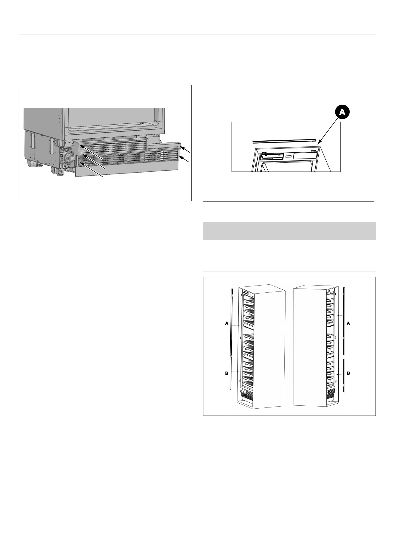
INSTRUCTIONS D’INSTALLATION
FIXATION DE L’ENSEMBLE DU TROU
D’AÉRATION
Utilisez 5 vis pour fixer l’assemblage du trou d’aération.
Fig. 37
FIXATION DES ÉLÉMENTS DÉCORATIFS
Fixez les pièces de fermeture latérales sur les supports de
connexion droit/gauche/supérieur.
Fig. 38
CATÉGORIE
A
REF18WCBPLV /
REF18WCBPRV
18″ (457 mm)
REF24WCBPNV
24″ (609 mm)
Fig. 39
A. 85″ (2 159 mm)
B. 24″ (617 mm)
A
A
B
A
B
92
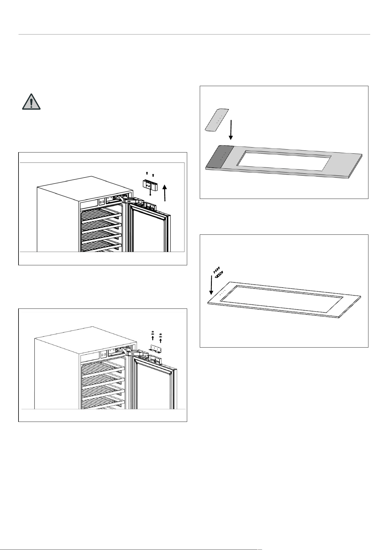
INSTRUCTIONS D’INSTALLATION
RETRAIT DES MÉCANISMES DE RÉGLAGE
DU PANNEAU DU RÉFRIGÉRATEUR
Retirez les vis pour ôter le couvercle du support de
suspension supérieur.
MISE EN GARDE
Il y a un aimant sur le couvercle du support
de suspension supérieur. Il s’agit d’une
partie fonctionnelle pour le fonctionnement
du produit. Il ne faut pas le confondre avec
le cintre bas
Fig. 40
Retirez les ensembles de mécanismes de réglage
supérieur et inférieur de la porte.
Fig. 41
PRÉPARATION DE LA PORTE DU MEUBLE
Lors du marquage, vous pouvez utiliser le « Modèle de
préparation de porte de meuble » fourni avec le produit.
Fig. 42
Installez les berceaux à l’aide des vis pour aggloméré.
Fig. 43
93

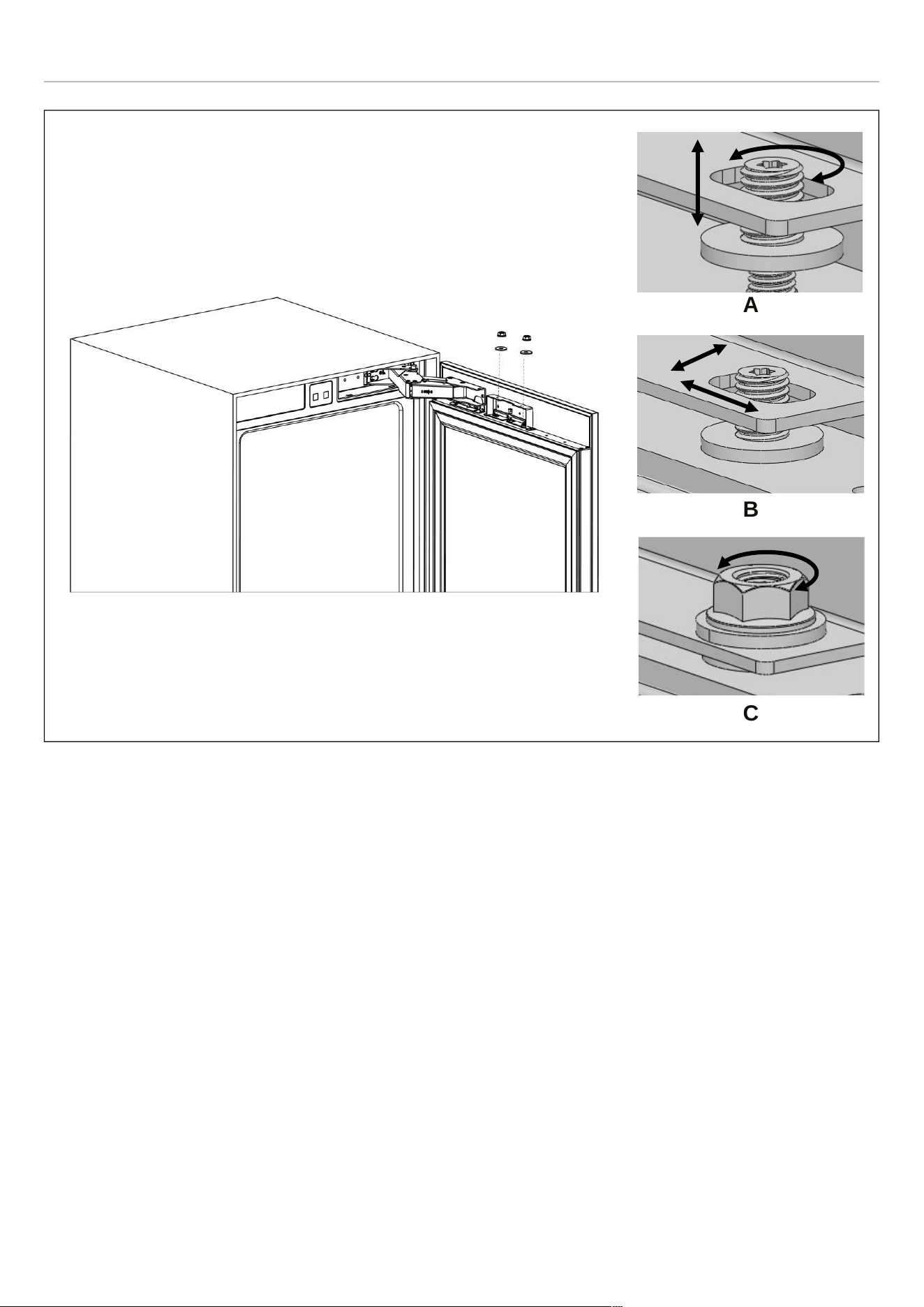
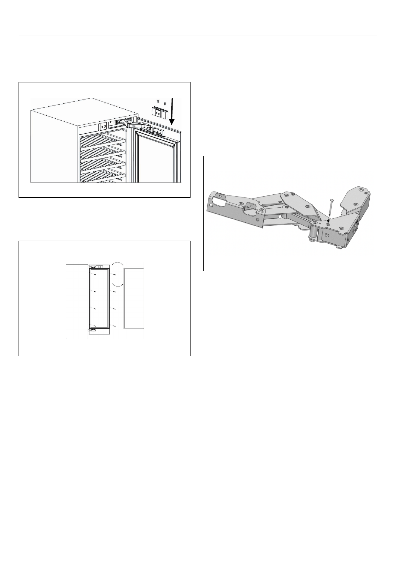
INSTRUCTIONS D’INSTALLATION
Comment aligner la partie supérieure de la porte du meuble
avec des boulons.
• Fixez et vissez le couvercle de décoration supérieur.
Fig. 47
• La gauche et la droite sont fixées en installant des vis
(ST4x35).
Fig. 48
GOUPILLES DE BUTÉE
La porte du réfrigérateur peut s’ouvrir jusqu’à un maximum
de 115°.
Si l’épaisseur de la porte est supérieure à 1 1/2″ (38 mm),
la porte ne doit pas s’ouvrir à plus de 90°. Dans ce cas, ou
si le réfrigérateur est placé à côté d’un mur, une goupille de
limitation à 90° doit être installée sur les charnières
supérieure et inférieure.
Assurez-vous que la goupille est bien en place dans le
support, sinon la porte ne se fermera pas correctement.
Fig. 49
96

INSTRUCTIONS D’INSTALLATION
RETRAIT DES ÉTAGÈRES
1) Retirer l’étagère à vin des glissières télescopiques
situées à l’avant.
2) Tirer l’étagère à vin vers l’avant. Le montant de fixation
des glissières télescopiques est verrouillé à l’arrière
dans la position indiquée sur la figure.
3) Relever l’étagère à vin pour la retirer.
ASSURER LA BONNE ÉTANCHÉITÉ DE LA
PORTE
Il est normal que le joint soit compressé après l’inversion
de la porte. Avec la porte fermée, utilisez un sèche-
cheveux pour dilater le joint et remplir l’espace entre la
porte et le bâti de l’appareil. Veillez à ne pas tenir le sèche-
cheveux trop près de l’appareil, ce qui pourrait
endommager le joint.
Une distance d’environ 10 cm devrait convenir. Une fois
terminé, laissez le joint et la porte refroidir avant de les
toucher. Une fois cela fait, le joint doit rester en place.
97

UTILISATION
AVANT LA PREMIÈRE UTILISATION
Retirer tous les emballages extérieurs et intérieurs.
Laisser l’appareil reposer en position verticale pendant
au moins 24 heures avant de le mettre sous tension.
Cela réduira le risque de dysfonctionnement du système de
refroidissement causé par la manutention pendant le
transport.
• Nettoyer l’intérieur du réfrigérateur comme recommandé
dans la section NETTOYAGE ET ENTRETIEN. Avant de
démarrer l’appareil, s’assurer que l’intérieur est sec.
• Brancher l’appareil dans une prise mise à la terre.
L’éclairage intérieur s’allume lorsque la porte est
ouverte.
• Faire fonctionner la colonne à vin pendant 6 heures
avant d’y placer des bouteilles et n’ouvrir la porte que si
cela est nécessaire.
NOTE
Un bruit est audible lorsque le compresseur
se met en marche. Les liquides et gaz
enfermés dans le système de réfrigération
peuvent également provoquer du bruit,
même si le compresseur ne fonctionne
pas. Ceci est tout à fait normal.
NOTE
Les bords à l’avant de l’appareil peuvent
être chauds. Ceci est normal. Ces zones
sont conçues pour être chaudes afin
d’éviter la condensation.
Pendant le fonctionnement, vous pouvez entendre des
bruits tout à fait normaux :
• Bourdonnement : Le réfrigérateur fonctionne. Le
ventilateur du système de recirculation d’air fonctionne.
• Bruits de bouillonnement, de bourdonnement ou de
gargouillement : le réfrigérant circule dans les tuyaux.
• Clic : le moteur se met en marche ou s’arrête.
La porte de 24″ (60 cm) l’appareil à colonne à vin large peut
être ouvert du côté gauche ou droit. L’appareil est livré
avec la porte s’ouvrant du côté gauche. Si vous souhaitez
ouvrir la porte par la droite, suivez les instructions incluses
dans ce manuel, à la section INVERSION DU
BATTEMENT DE LA PORTE (LE CAS ÉCHÉANT).
Si vous avez reçu un produit endommagé, contactez
immédiatement le revendeur ou le distributeur auprès
duquel vous avez acheté le produit.
Lisez attentivement et suivez ces instructions pour
l’installation, l’utilisation et l’entretien de l’appareil.
Lisez la section de dépannage de ce manuel, qui vous
aidera à diagnostiquer et à résoudre les problèmes les plus
courants.
98
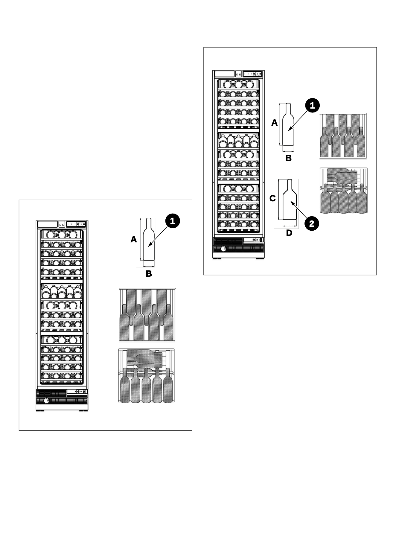
UTILISATION
ENTREPOSAGE INTERNE
Cette colonne à vin est dotée de 3 zones de température
indépendantes, chacune réglable de 5 à 2041 à 68℉ (5 à
20℃).
Les figures de cette section présentent deux schémas de
charge différents. Suivez celui qui correspond le mieux à
vos besoins.
Les étagères en bois peuvent être retirées pour augmenter
la capacité de charge, mais rendent l’appareil moins
pratique pour une utilisation quotidienne. Pour retirer une
étagère, veuillez consulter le paragraphe RETRAIT DES
ÉTAGÈRES.
La configuration la plus économe en termes d’énergie
nécessite l’installation d’étagères dans l’appareil ; veuillez
vous référer aux images ci-dessus.
Fig. 50 ENTREPOSAGE DE BOUTEILLES A
REF24WCBPNV
Fig. 51 ENTREPOSAGE DE BOUTEILLES B
REF24WCBPNV
A. 11 13/16″
B. 3″
C. 11 13/16″
D. 3 3/4″
1
A
B
A
C
B
D
1
2
99

UTILISATION
CAPACITÉ DE CHARGE
REF24WCBPNV
ENTREPOSAGE DE
BOUTEILLES A
ENTREPOSAGE DE BOUTEILLES B
(BOUTEILLE 1- TYPE
BORDEAUX)
(BOUTEILLE 1- TYPE
BORDEAUX)
(BOUTEILLE 2- TYPE
BOURGOGNE)
Zone supérieure
1 7 \
5
2 7 7 \
3 7 7 \
4 7 7 \
5 7 7 \
Zone intermédiaire
1 9 6 3
2 7 \
5
3 7 7 \
4 7 7 \
Zone inférieure
1 7 \
5
2 7 7 \
3 7 7 \
4 7 7 \
5 7 7 \
Total 100 76 18
100


UTILISATION
CAPACITÉ DE CHARGE
REF18WCBPLV,
REF18WCBPRV
ENTREPOSAGE DE
BOUTEILLES A
ENTREPOSAGE DE BOUTEILLES B
(BOUTEILLE 1- TYPE
BORDEAUX)
(BOUTEILLE 1- TYPE
BORDEAUX)
(BOUTEILLE 2- TYPE
BOURGOGNE)
Zone supérieure
1
5
\ 3
2
5 5
\
3 5 5
\
4
5 5
\
5 5 5
\
Zone intermédiaire
1 3 \ 3
2
5
\ 3
3 5 5
\
4
5 5
\
Zone inférieure
1
5
\ 3
2
5 5
\
3 5 5
\
4
5 5
\
5 5 5
\
Total 68 50 12
102
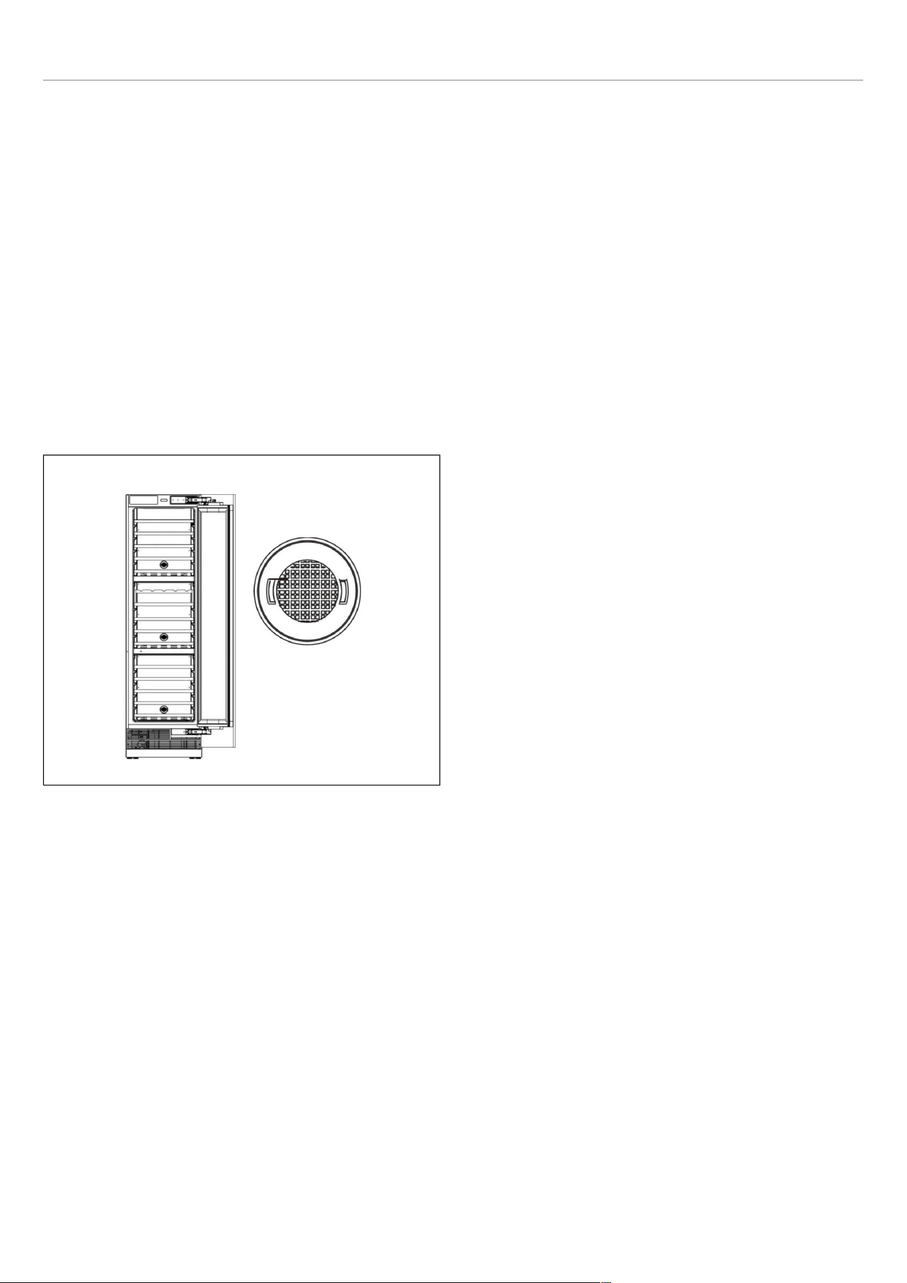
UTILISATION
FILTRE À CHARBON
Trois filtres à charbon intégrés servent de barrière naturelle
contre les odeurs nocives, assurant la protection de vos
boissons.
Pour maintenir des performances optimales, il est
recommandé de remplacer le filtre à charbon tous les 3 à 6
mois, en fonction de l’exposition de l’appareil aux odeurs.
Si l’appareil est situé dans une cuisine, il est idéal de
remplacer le filtre tous les trois mois.
Pour retirer le filtre à charbon, il suffit de le tourner dans le
sens inverse des aiguilles d’une montre pour le
déverrouiller du panneau arrière.
Les filtres de rechange peuvent être commandés auprès
du revendeur de votre choix.
Fig. 54
103

UTILISATION
RECOMMANDATIONS POUR LA
CONSERVATION ET LE SERVICE DU VIN
Pour apprécier au mieux les qualités organoleptiques de
chaque vin, il est nécessaire que le stockage et la
consommation se fassent à certaines températures.
Le tableau suivant résume la température de conservation
la plus adaptée à chaque type de vin. Il est recommandé,
notamment pour les bouteilles de plus grande valeur, de
suivre à la lettre les instructions fournies par le producteur.
TYPE DE VIN
TEMPÉRATURE D’ENTREPOSAGE (℉℉)
Vins blancs jeunes et légers
50-54
Vins blancs à maturité et structurés 54-57
Vins blancs aromatiques
46-50
Vins rosés jeunes et légers
50-54
Vins rosés à maturité et corsés 54-57
Vins rouges jeunes
50-57
Vins rouges jeunes, légèrement tanniques et légers
57-61
Vins rouges à maturité, tanniques et corsés
16-18
Vins rouges très à maturité, tanniques et corsés
61-64
Vins mousseux doux et aromatiques
46-50
Vins rouges mousseux doux et aromatiques
50-54
Vins mousseux méthode Charmat 46-50
Vins mousseux méthode long méthode Charmat
50-54
Vins mousseux méthode classiques ou Charmat
46-50
Vins mousseux méthode classiques « Millesimato »
50-54
Vins mousseux secs et demi-secs 46-50
Vins pétillants
50-54
Vins mousseux doux supérieurs
50-54
Vins fortifiés, de dessert ou de paille
50-64
104

UTILISATION
VINS BLANCS
Les vins blancs ne se servent généralement pas à haute
température, car ils sont généralement plus acides que les
vins rouges et peu tanniques, raison pour laquelle ils sont
plus appréciés à basse température.
Ces vins doivent de préférence être conservés et servis
entre 10 ℃ et 14 ℃ (50 ℉ et 57 ℉). Les vins jeunes,
frais et aromatiques peuvent également être servis à 10 ℃
(50 ℉), tandis que les moins aromatiques sont
recommandés à 12 ℃ (54 ℉). Les températures entre 12
℃ et 14 ℃ (54 ℉ et 57 ℉) conviennent aux vins blancs
souples et à maturité vieillis quelques années en bouteille.
Des températures plus élevées favoriseraient
l’accentuation du caractère sucré du vin, au détriment de
l’acidité et de la saveur qui sont considérées comme des
caractéristiques agréables et souhaitables pour ce type de
vin.
VINS ROSÉS
Les vins rosés se servent généralement à la même
température que les vins blancs. Il faut cependant noter
que ces vins peuvent contenir une certaine quantité de
tannins et il peut donc être préférable de les déguster à des
températures plus élevées pour ne pas les rendre trop
astringents. Ainsi, on les sert entre 10 et 12 ℃ (50 et 54
℉) s’ils sont jeunes et frais et entre 12 et 14 ℃ (54 et 57
℉) s’ils sont plus charpentés et matures.
VINS ROUGES
Contenant plus de tannins et étant moins acides, les vins
rouges se servent généralement à des températures plus
élevées.
Les vins plus jeunes et moins tanniques se servent
généralement entre 14 et 16 ℃ (57 et 61 ℉), tandis que
les vins plus corsés et tanniques peuvent être servis à 16
℃ (64 ℉), et exceptionnellement même à 18 ℃ (64 ℉).
Certains vins vieillis plusieurs années en bouteille, encore
corsés et tanniques, peuvent être servis à 18° ℃ (64 °℉)
voire à 20 ° ℃ (68 ° ℉). Les vins rouges jeunes, peu
tanniques et moins structurés, peuvent être dégustés à des
températures plus basses, entre 12 et 14 °℃ (54 ° et 57 °
℉).
LES VINS MOUSSEUX MÉTHODE CLASSIQUE OU
CHARMAT
Étant donné la grande variété de vins mousseux existants,
il est difficile de donner des recommandations valables
pour tous.
De manière générale, les vins mousseux plus doux et
aromatiques doivent être servis à des températures plus
basses, jusqu’à 8 ℃ (46 ℉), en raison de leur aromatique.
Les vins mousseux plus tanniques peuvent être servis à
des températures plus élevées, jusqu’à 14 ℃ (57 ℉).
Les vins mousseux secs de la méthode Charmat ou
Martinotti, comme certains Proseccos, doivent
généralement être servis entre 8 et 10 ℃ (46 et 50 ℉).
Les vins mousseux méthode classique et champenoise tels
que le Champagne sont également normalement servis à
ces températures, mais pour les vins mousseux vieillis un
certain temps tels que le Millesimati, peuvent être servis
jusqu’à 12 ° ℃ (54 ℉) pour favoriser le développement
d’arômes complexes.
Il est toutefois conseillé, surtout pour les meilleurs vins, de
suivre les recommandations du producteur, imprimées sur
la bouteille.
VINS MOUSSEUX
Pour les vins pétillants, les indications de température sont
les mêmes que pour les vins mousseux de la méthode
classique ou Charmat et sont généralement servis entre 10
et 12 °℃ (50 et 54 ° ℉). Pour les vins mousseux secs et
demi-secs, une température de service légèrement
inférieure, comprise entre 8 et 10° ℃ (46 et 50 ° ℉), est
recommandée.
105

UTILISATION
VINS FORTIFIÉS, DE DESSERT OU DE PAILLE
Ce type de vin peut être servi à des températures
comprises entre 14 et 18 °℃ (61 et 64 °℉) selon les goûts
de chacun et, pour atténuer le goût sucré et la forte teneur
en alcool, il peut également être servi à 10 °℃ (50 °℉).
Les vins de liqueur secs, comme le Marsala par exemple,
contiennent tellement de sucre qu’ils ne sont pas perçus en
bouche. Pour ces vins, la température de service doit être
réglée en fonction de ce que l’on souhaite mettre en valeur.
Si vous préférez accentuer la douceur du vin, la complexité
de son bouquet et son austérité, il est préférable de le
servir à une température élevée, entre 14 °℃ et 18 °℃(61
et 64 ℉), en gardant à l’esprit que cela renforcera
également la composante alcoolique. Si vous souhaitez
davantage accentuer leur fraîcheur, il faudra les servir à
une température plus basse, entre 10 ℃ et 14 ℃ (50 et
61 ℉). Les vins de liqueur secs, frais et jeunes peuvent
également être servis à une température plus fraîche,
inférieure à 10 ℃ (50 ℉), afin de réduire considérablement
la perception de l’alcool. Cependant, plus la température
de service est basse, moins la perception des arômes sera
importante. Le plaisir et la complexité des arômes typiques
de ces vins sont une caractéristique bienvenue et
intéressante : les servir trop froids signifie sacrifier cet
aspect important.
106
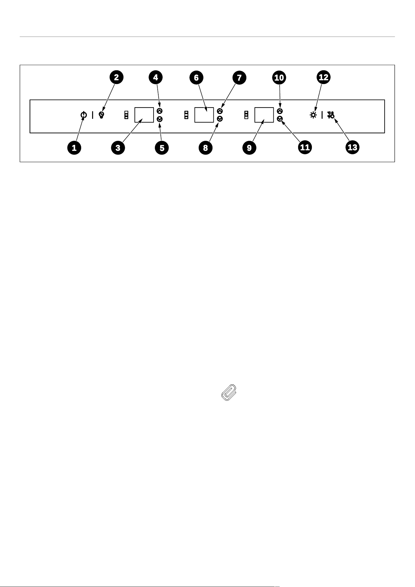
UTILISATION
PANNEAU DE COMMANDE
Fig. 55
1) Bouton Marche/Arrêt (On/Off)
2) Mode Sabbat
3) Température de la zone supérieure
4) Bouton d’augmentation de la température de la zone
supérieure
5) Bouton de diminution de la température de la zone
supérieure
6) Température de la zone intermédiaire
7) Bouton d’augmentation de la température de la zone
intermédiaire
8) Bouton de diminution de la température de la zone
intermédiaire
9) Température de la zone inférieure
10) Bouton d’augmentation de la température de la zone
inférieure
11) Bouton de diminution de la température de la zone
inférieure
12) Bouton d’éclairage
13) Sélection des degrés Celsius et Fahrenheit
BOUTON MARCHE/ARRÊT (ON/OFF)
Cette touche sert à allumer et à éteindre l’ensemble de
l’appareil. Appuyez sur [1] pendant 3 secondes pour
allumer/éteindre l’appareil. Lorsqu’il est éteint, l’appareil se
déconnecte de toutes les sources d’alimentation externes
et passe en mode veille.
ACTIVATION/DÉSACTIVATION DE LA SÉCURITÉ
ENFANT
La sécurité enfant est une fonction permettant d’empêcher
les enfants de modifier les réglages de l’appareil. Appuyez
simultanément sur les boutons [12] + [13] pour verrouiller/
déverrouiller le panneau de commande.
Lorsque la sécurité enfant est activée, les valeurs de
température des affichages numériques clignotent
simultanément pendant 3 secondes, accompagnées d’un
signal sonore pour indiquer que l’affichage est verrouillé.
Désactivez le verrouillage enfant pour modifier les
paramètres.
BOUTONS DE RÉGLAGE DE LA TEMPÉRATURE
Appuyez sur les boutons [4] , [7] et [10] pour augmenter la
valeur de température d’un degré à chaque pression.
Appuyez sur les boutons [5] , [8] et [11] pour diminuer la
valeur de température d’un degré à chaque pression. La
température peut être réglée de 5 °℃ (41 °℉) à 20 °℃ (68
°℉) dans chaque zone de température.
NOTE
Lorsque vous modifiez la température des
trois zones, les écrans continuent d’afficher
initialement la température actuelle des
trois zones. Les valeurs affichées sur les
écrans changent progressivement jusqu’à
ce que les températures de consigne
souhaitées soient atteintes. L’appareil met
un certain temps à atteindre les nouvelles
températures de consigne ; ceci est
normal.
10
7
6
4
2 12
11
98
5
31
13
107

UTILISATION
SÉLECTION DE LA NUANCES DE LUMIÈRE,
SÉLECTION DE LA LUMINOSITÉ ET MODE
DIVERTISSEMENT
L’allumage/extinction des lampes LED dépend de
l’ouverture/la fermeture de la porte. Lorsque la porte est
ouverte, les lumières s’allument automatiquement. Lorsque
la porte est fermée, les lumières s’éteignent pour
économiser de l’énergie.
Pour sélectionner la nuance de lumière, appuyez sur le
bouton [12] pour changer la couleur de l’éclairage LED
entre ambre, bleu ou blanc.
Appuyez sur le bouton [12] pendant 3 secondes pour
activer le mode divertissement et garder la lumière allumée
en permanence même lorsque la porte est fermée. Les
écrans des trois zones de température afficheront « ON »
pendant 5 secondes. Après 5 secondes, les écrans
numériques afficheront à nouveau les températures
réglées dans les 3 zones.
Pour régler la luminosité des lumières, appuyez sur [12]
jusqu’à ce que tous les écrans numériques des trois zones
de température affichent « ON ». Dans les 5 secondes,
appuyez sur [4] , [5] , [7] , [8] , [10] , [11] pour régler la
luminosité des lampes à LED parmi sept niveaux, par
incrémentation de luminosité de L1 à L7.
SÉLECTION DES DEGRÉS CELSIUS ET FAHRENHEIT
Appuyez sur le bouton [13] pour basculer entre Celsius et
Fahrenheit Chaque pression permet de basculer. Celsius
est défini comme valeur par défaut d’usine.
MODE EXPOSITION
Appuyez simultanément sur les boutons [1] + [2] pendant
3 secondes pour activer la fonction.
Ce mode est utilisé lorsque le réfrigérateur est exposé dans
un magasin de détail ou si vous souhaitez éteindre le
refroidissement et désactiver toutes les autres fonctions à
l’exception de l’éclairage intérieur. Lorsque cette fonction
est activée, les affichages numériques des 3 zones de
température affichent tous « Sn ». Le mode se désactive
automatiquement si aucun bouton n’est appuyé pendant
72 heures. Appuyez simultanément sur [1] + [2] pour
désactiver le mode exposition à tout moment.
NOTE
N’entreposez aucun article en mode
exposition, car l’appareil reste alors à
température ambiante.
108

UTILISATION
MODE SABBAT
Appuyez sur [2] pour activer/désactiver la fonction.
Lorsque le mode Sabbat est activé, toutes les lumières, les
buzzers, les écrans numériques s’éteignent. Le
compresseur et le ventilateur continuent de fonctionner
normalement. Le mode est automatiquement désactivé
après 96 heures de fonctionnement. Si l’appareil est éteint,
l’état est maintenu. Appuyez sur [2] pour désactiver le
mode Sabbat à tout moment.
NOTE
Lorsque vous réglez la température sur le
panneau de commande, celui-ci affiche la
température actuelle. La lecture changera
progressivement pour refléter la
température interne jusqu’à ce qu’elle
corresponde au réglage souhaité. Veuillez
noter qu’il peut falloir un certain temps pour
que la cave à vin atteigne la nouvelle
température, ce qui est tout à fait normal.
Vous n’avez pas besoin de régler la
température souhaitée simplement parce
que l’écran n’affiche pas immédiatement
votre préférence.
S’il y a de l’humidité ou du liquide sur le
panneau de commande, il peut ne pas
fonctionner correctement. Veuillez essuyer
la surface avec un chiffon sec et réessayer.
FONCTION DE MÉMOIRE DE PANNE DE
COURANT
PLAGES DE TEMPÉRATURES :
• Zone supérieure : 41℉ - 68℉ (5-20℃)
• Zone intermédiaire : 41℉ - 68℉ (5-
20℃)
• Zone inférieure : 41℉ - 68℉ (5-20℃)
109
PRÉCAUTIONS ET MAINTENANCE
MISE EN GARDE
Débranchez toujours l’appareil de
l’alimentation secteur avant d’effectuer tout
nettoyage ou entretien.
INSTRUCTIONS DE REMPLACEMENT DE
L’ÉCLAIRAGE À LED
Pour assurer un éclairage intérieur optimal, des bandes
LED éclairent l’appareil par le haut et des jeux de lumières
LED éclairent directement différentes zones.
En cas de dysfonctionnement et/ou d’usure du système
d’éclairage, les réparations doivent être effectuées par un
technicien de service qualifié.
NETTOYAGE DES SURFACES INTÉRIEURES
Pour nettoyer l’intérieur de la colonne à vin, ouvrir la porte
et retirer les étagères. Essuyer l’intérieur de l’appareil à
l’aide d’un chiffon propre et un détergent doux ou avec une
éponge douce et une solution de bicarbonate de soude et
d’eau tiède. Ne pas utiliser de produits ou de détergents
abrasifs. Après le lavage, rincer et sécher soigneusement.
Nettoyer les étagères en bois à l’aide d’un chiffon doux
légèrement humide. Éviter d’utiliser des savons, des
détergents et/ou des éponges qui peuvent endommager
les surfaces en bois et en acier. Sécher soigneusement les
étagères avant de les replacer dans la colonne à vin.
MISE EN GARDE
Ne pas utiliser de vinaigre, d’alcool à brûler
ou d’autres produits de nettoyage à base
d’alcool sur les surfaces intérieures.
Si l’appareil ne va pas être utilisé pendant une période
prolongée, débranchez et nettoyez l’appareil. Les portes
doivent être laissées légèrement entrouvertes pour éviter la
formation de moisissures et d’odeurs désagréables.
NETTOYAGE DES SURFACES EXTÉRIEURES
Pour nettoyer la porte et le meuble, utilisez une solution
détergente douce composée de deux cuillères à soupe de
bicarbonate de soude par litre d’eau tiède. Évitez d’utiliser
des produits de nettoyage abrasifs ou corrosifs.
Évitez d’utiliser des nettoyants à base de solvants ou
abrasifs. Utilisez une éponge douce pour le nettoyage,
rincez à l’eau claire et séchez avec une serviette douce
pour éviter les taches d’eau.
Si le panneau de porte est en acier inoxydable, sachez que
l’exposition au chlore gazeux et à l’humidité peut provoquer
une décoloration. Nettoyez l'acier inoxydable avec un
chiffon imbibé d’une solution de détergent doux et d’eau
chaude.
Évitez d’utiliser des produits de nettoyage abrasifs ou
corrosifs.
DÉCONGÉLATION
La colonne à vin est conçue avec un système de dégivrage
automatique. Cependant, sur des réglages plus froids, du
givre peut s'accumuler. De plus, plus les conditions
ambiantes sont humides, plus le givre peut s’accumuler.
Garder la porte fermée autant que possible et éviter de
l’ouvrir inutilement pour minimiser l’accumulation de givre.
Si le givre empêche la porte de se fermer correctement,
vous devrez peut-être éteindre l’appareil jusqu’à ce que le
givre fonde (éventuellement jusqu’à 24 heures). Utiliser un
chiffon doux et absorbant pour sécher l’appareil.
MISE EN GARDE
Ne pas endommager les tuyaux de
réfrigération.
110

PRÉCAUTIONS ET MAINTENANCE
BRUITS ET SIGNIFICATION
Cette colonne à vin peut émettre des sons normaux
pendant son fonctionnement.
Les surfaces dures telles que le sol ou les murs peuvent
donner l’impression que les sons sont plus forts qu’ils ne le
sont en réalité.
Vous trouverez dans la liste ci-dessous les sons les plus
courants et leurs causes :
• Cliquetis : en raison du flux de réfrigérant ou d’objets
placés sur l’appareil.
• Sons forts ou aigus : le compresseur à haut rendement
peut émettre des sons en raison de son fonctionnement
normal.
• Bruit d’éclaboussure : dû à l’eau qui s’écoule de
l’évaporateur vers le réservoir d’eau.
• Bruit de gargouillement : réfrigérant qui s’écoule dans
l’appareil.
• Bruit d’air : on entend l’air poussé sur le condenseur par
le ventilateur du condenseur.
PANNE DE COURANT
La plupart des pannes de courant sont résolues en
quelques heures et ne devraient pas affecter la
température de l’appareil si le nombre de fois où la porte
est ouverte est réduit au minimum. Si la panne de courant
se prolonge, des mesures appropriées doivent être prises
pour protéger le contenu de votre appareil.
111

RÉSOLUTION DE PROBLÈMES
Si vous rencontrez des problèmes avec votre appareil,
vous devez consulter cette section de Résolution de
problèmes avant d’appeler le service client.
Si l’appareil ne fonctionne pas, vérifiez que :
• L’appareil est sous tension.
• Les fusibles de la maison sont intacts et le fusible de la
prise n’a pas sauté.
• L’appareil n’a pas été éteint.
• La prise électrique fonctionne correctement. Pour le
vérifier, branchez-y un autre appareil électrique pour voir
si la prise est défectueuse.
Si l’appareil fonctionne, mais pas très bien, vérifiez
que :
• L’appareil n’est pas en surcharge.
• Le thermostat est réglé sur une température appropriée.
• Les portes se ferment correctement.
• Le système de refroidissement à l’arrière de l’appareil
est propre et sans poussière et ne touche pas la paroi
arrière.
• Il y a suffisamment de ventilation autour des parois
latérales et arrière.
Si l’appareil n’est pas suffisamment froid, vérifiez que :
• La température n’est pas trop élevée.
• L’appareil n’est pas installé à côté d’une source de
chaleur.
• La porte n’est pas ouverte trop fréquemment ou pendant
de longues périodes.
• Le joint de porte est bien étanche.
• L’appareil n’est pas réglé sur le mode démo.
• L’appareil est suffisamment ventilé et est installé
conformément aux exigences d’installation spécifiées
dans ce manuel.
Si l’appareil est bruyant ou s’allume et s’éteint
fréquemment, vérifiez que :
• L’appareil est de niveau et stable.
• Les étagères sont correctement positionnées à
l’intérieur de l’appareil.
• La température ambiante est plus élevée que la
normale.
• Le joint de la porte est correctement scellé.
• La porte n’est pas ouverte trop fréquemment ou pendant
de longues périodes.
• L’appareil est suffisamment ventilé et est installé
conformément aux exigences d’installation spécifiées
dans ce manuel.
NOTE
Le gaz réfrigérant dans le réfrigérateur peut
faire un léger bruit de bouillonnement ou de
gargouillis, même lorsque le compresseur
ne fonctionne pas.
NOTE
Certains bruits de claquement ou de
craquement sont normaux. Ils sont dus à la
dilatation et la contraction des parois
intérieures en raison des changements de
température.
Si l’appareil émet un bip, vérifiez que :
• Les portes sont fermées. Une alarme retentit après
qu’une porte a été ouverte pendant 60 secondes.
Si du givre s’est formé dans l’appareil :
• L’environnement est trop humide.
• La température de la pièce est trop basse.
• La porte est ouverte trop fréquemment.
• L’appareil est équipé d’un système de dégivrage
automatique, mais dans certaines conditions, un
dégivrage manuel peut être nécessaire. Si du givre se
forme périodiquement, essayez de faire fonctionner le
réfrigérateur à une température plus élevée, en
minimisant le nombre d’ouvertures de porte ou en
débranchant l’appareil pour permettre au givre de
fondre.
• Vérifiez pour tout pli, débris ou dommage au niveau du
joint de la porte. Si vous en remarquez et que vous ne
parvenez pas à résoudre le problème vous-même,
contactez le service client afin que le joint puisse être
remplacé.
• Cela peut être dû au fait que la ou les portes de l’armoire
ne sont pas correctement installées. En cas de doute,
demandez à votre installateur de vérifier les portes de
l’armoire.
Si une ou plusieurs des unités LED à l’intérieur de
l’appareil ne fonctionnent pas :
• Contactez le service client pour organiser une visite de
service.
Si le châssis de l’appareil est électrifié :
• L’unité n’est pas correctement mise à la terre. Contactez
votre électricien pour tester votre système de mise à la
terre électrique.
112

CODES D’ERREUR
En cas de dysfonctionnement, contactez un technicien de
service pour les réparations
EXPLICATION CODE DE CIRCUIT OUVERT CODE DE COURT-CIRCUIT
Sondes en armoire au-dessus de la zone
E1 E2
Sonde de givrage au-dessus de la zone
E3 E4
Sonde en armoire de la zone intermédiaire
E5
E6
Sonde de givrage de la zone intermédiaire
E7 E8
Sondes en armoire au-dessus de la zone
E9 E10
Sonde de givrage en dessous de la zone
E11 E12
NOTE
1) Lorsqu’il y a un code d’erreur, le buzzer
émettra trois sons d’alarme consécutifs
« Tic » « Tic » « Tic », le code d’erreur
clignote toutes les 10 secondes pendant
un cycle et l’alarme sera activée si vous
souhaitez arrêter la sonnerie de
l’alarme.
Si vous souhaitez désactiver la sonnerie
de l’alarme, appuyez sur la touche
marche/arrêt.
2) Chaque fois qu’une touche est
enfoncée, le buzzer émet un « Tic ».
113


www.bertazzoni.com
Via Palazzina, 8,
42016 Guastalla RE
© 2025 BERTAZZONI. All rights reserved.
REF...WCBP...V_UIM_US_v.03