
Le
Griddle
Gas Models
GFE40 - GFE75 – GFE105 – GFE160
Installer-please leave this manual with the proud new owner.
Instruction Manual
For the latest news and product updates, please visit:
LeGriddleUS.com [email protected] REV 08.26.2024
Page 1
Dear Customer,
Thank you for purchasing this Le Griddle product. It is very easy to use, but we strongly recommend that
you carefully read these instructions which includes directions on how to use and install your appliance
in order to obtain optimum and safe results.
Receiving
and
unpacking:
Should you notice any damage when unpacking, please contact your retailer.
General
rules
applicable
to
gas
equipment
GRIDDLE INSTALLATION
This gas griddle must be installed in accordance with all local codes. If installation is planned in an area
with no local codes, the gas grill must be installed in accordance with the National Fuel Gas Code ANSI
Z223.1 and storage and handling of liquefied petroleum gases, ANSI/NFPA 58 or CSA B149.1 natural gas
and propane installation code.
Installation in Canada must be in accordance with the standard CAN/CGA- B149.2.T
State of California Proposition 65 Warnings:
This product contains chemicals known to the State of California to cause cancer, birth defects or other
reproductive harm.
IMPORTANT SAFETY NOTICE: The Ca
lifornia Safe Drinking Water and Toxic Enforcement Act
requires the State of California to publish a list of substances known to the State to cause cancer, birth
defects or other reproductive harm, and requires businesses to warn customers of potential exposure to
such substances.
The burning of gas cooking fuel can generate some by-products
which are on the list. To minimize
exposure to these substances, always operate this unit according to the instructions contained in this
booklet and provide good ventilation.
Birds have very sensitive respiratory systems. Keep pet birds out of the kitchen or other rooms where
kitchen fumes could reach them. Kitchen fumes such as overheating margarines and cooking oils may be
harmful.
If you smell gas:
1.
Shut off gas to appliance.
2.
Extinguish any open flame.
3.
Open lid.
4.
If odor continues, keep away from the appliance and immediately call your gas supplier or your
fire department.
1. Do not s
tore or use gasoline or other flammable liquids or vapors in the vicinity of this or any other
appliance.
2. An LP cylinder not connected for use shall not be stored in the vicinity of this or any other
appliance.
STATE OF MASSACHUSETTS !!! WARNING !!!
Massachusetts requires all gas appliances to be installed using a plumber or gas fitter carrying the
appropriate Massachusetts license. All permanently-installed natural gas or propane installations require a
"T" handle type manual gas valve be installed in the gas supple line to this appliance. This does not apply
to portable propane installations using a 20-pound cylinder.
IMPORTANT : REMOVE ALL PROTECTIVE FILM BEFORE USE
Page 2Page 2

Please read all the
instructions carefully.
When using gas appliances, safety measures must always be taken:
•
This appliance is not designed for use by people (including children) whose physical, sensorial or
mental capacities are impaired or by people with no experience or knowledge, unless they have been
supervised or given training in the use of the appliance beforehand by a person responsible for their
safety.
•
Some parts can be hot, keep children away from this appliance.
•
The appliance must never be left without supervision during use.
• Do not move the appliance during operation.
• Do not us
e the appliance for anything other than the purpose which is intended.
• There is a risk of accidents if accessories used which not recommended by the manufacturer of the
appliance.
• This appliance must be kept away from flammable materials.
• If you smell gas, turn off all the valves.
• Never operate an appliance that has a gas leak.
• Use protective gloves when handling particularly hot parts of the appliance.
• Allow the appliance to cool down before handling.
• Use this appliance out of the wind.
• The underneath of the appliance must be kept well-ventilated to ensure good air circulation to the
burner(s).
• Place the appliance on a non-combustible stable, dry surface, slightly away from the edge and more
than 12 inches away from any walls or heat-sensitive objects.
• Recommended cooking height: 33 to 37 inches from the ground for a comfortable working position.
• Close the gas cylinder or supply valve after each use.
Any modification of the appliance may be dangerous and will void the warranty. Do not modify this
appliance.
• Do not use an adjustable or high-pressure gas regulator.
• Do not obstruct the ventilation openings around the frame.
• Do not use or store any flammable liquids or vapors in the vicinity of the Griddle.
• Close the valve on the gas cylinder when the griddle is not in use. Store the appliance in a dry, well-
ventilated place.
• We recommend that you keep the original packing to store the appliance.
• KEEP THESE INSTRUCTIONS
• Le Griddle cannot be held responsible for any damage incurred to objects or people resulting from
incorrect installation or operation of the appliance.
DO NOT connect high pressure gas to the Le Griddle. These griddles use low pressure, 1/2"
psi to operate correctly. For use with natural gas, the regulator is not provided. In case of
conversion to LP Gas an example of an approved regulator and hose kit would be the
RONHK which you may purchase locally or order on line at www.LeGriddleUS.com.
Page 3
Technical
Description
Characteristics
• Stainless steel frame
• Stainless steel cooking plate certified for contact with food
• Stainless steel burners
• Thermocouples (automatic gas cut-out if flame goes out)
• Flame protection from normal wind
• Electronic ignition (battery AA included)
Uses LP gas or natural gas (may require gas conversion)
• Trim on 3 sides
• Removable grease tray for liquid and waste recovery
• A protective cover (optional)
Reference
Size in inches
W x D x H
Gas
Weight
BTU
Orifices Cooking
surface
Cooking
Material
Gas
Connection
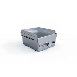
GFE40
16,5x18,75x10
PROPANE
or
NATURAL
GAS
52lb
1 X 9000
0,9
(LPG)
1.40
(NG)
16x15,75
Stainless
steel +
Cast iron
3/8 FLARE
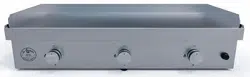
GFE75
30
x18,75x10
PROPANE
or
NATURAL
GAS
98lb
2 X 9000
0,9
(LPG)
1.40
(NG)
29x15,75
Stainless
steel +
Cast iron
3/8 FLARE
GFE105
41x18,75x10
PROPANE
or
NATURAL
GAS
120lb
3 X 9000
0,9
(LPG)
1.40
(NG)
41,25x15,75
Stainless
steel +
Cast iron
3/8 FLARE
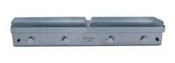
GFE160
61,7
x18,75x10
PROPANE
or
NATURAL
GAS
203lb
4 X 9000
0,9
(LPG)
1.40
(NG)
2 Plates
29x15,75
Stainless
steel +
Cast iron
3/8 FLARE
Page 4
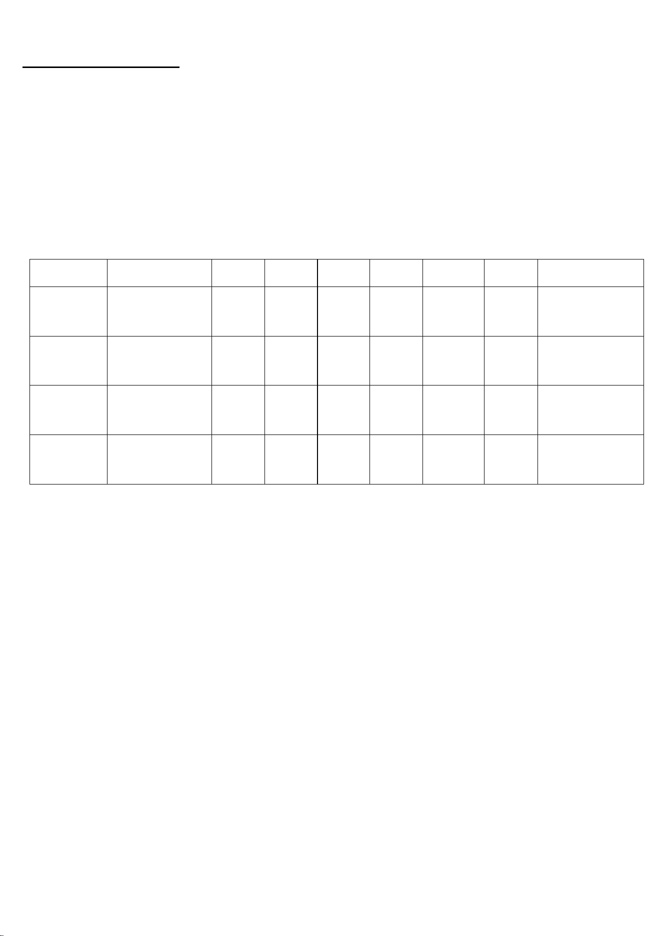
1. Before installation follow these steps to connect the appliance to the gas supply.
Take your griddle body (Box 1 OF 2) out of the packaging with care and
remove the grease tray from the unit.
2.
3.
Flip the unit upside down and put it on a soft flat surface to prevent
scratches as shown in (Fig.1). You can access the gas connection of
the appliance easily (Fig.2), to make the connection safely by following
the instructions below.
4.
Fig.1
Fig.2
Le Griddle Gas Connection Steps
Make sure all the knobs are in the OFF
position: (The arrow on the knob should
be pointing to the OFF position).
Page 5
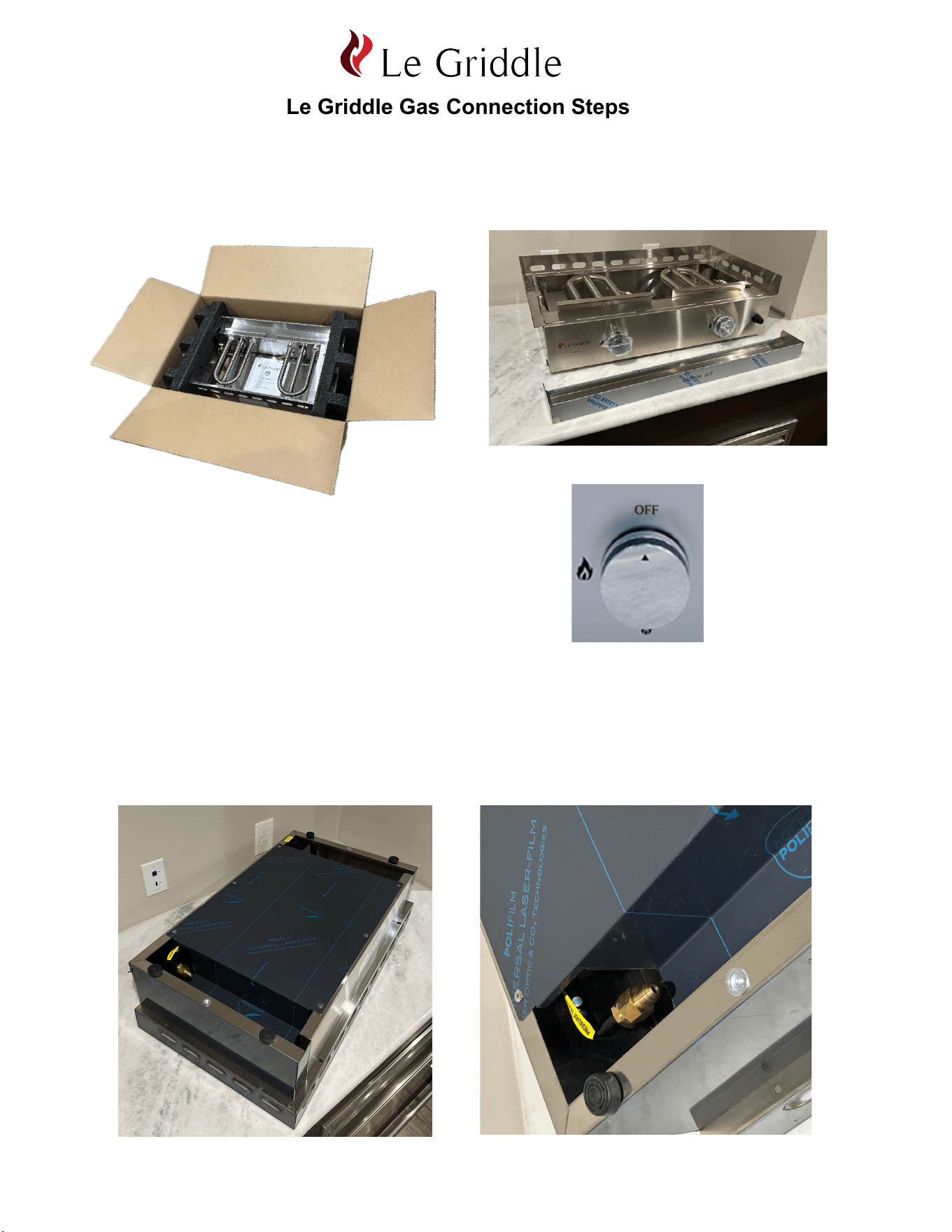
For Propane Installation Follow these Directions - (See page 4 for Natural Gas)
For use with LP Gas, we recommend using the regulator and hose kit RONHK
(not included). Be sure to keep the LP gas tank as far away as possible from
any heat sources. Check that the hose is in good condition and replace it if it
looks cracked or damaged. The hose should not be twisted or pulled and should
not come into contact with hot parts of the appliance.
1.
Regulator type RONHK for LP
3/8" Female flare
connection
Fig. 3
Connect the propane hose kit to the unit:
1. Attach the 3/8" Female flare end to the 3/8" Male flare connection (Fig. 4)
by screwing/rotating the brass fitting in a clockwise rotation by hand until
it stops (Fig. 5).
2.
Fig. 4 Fig. 5
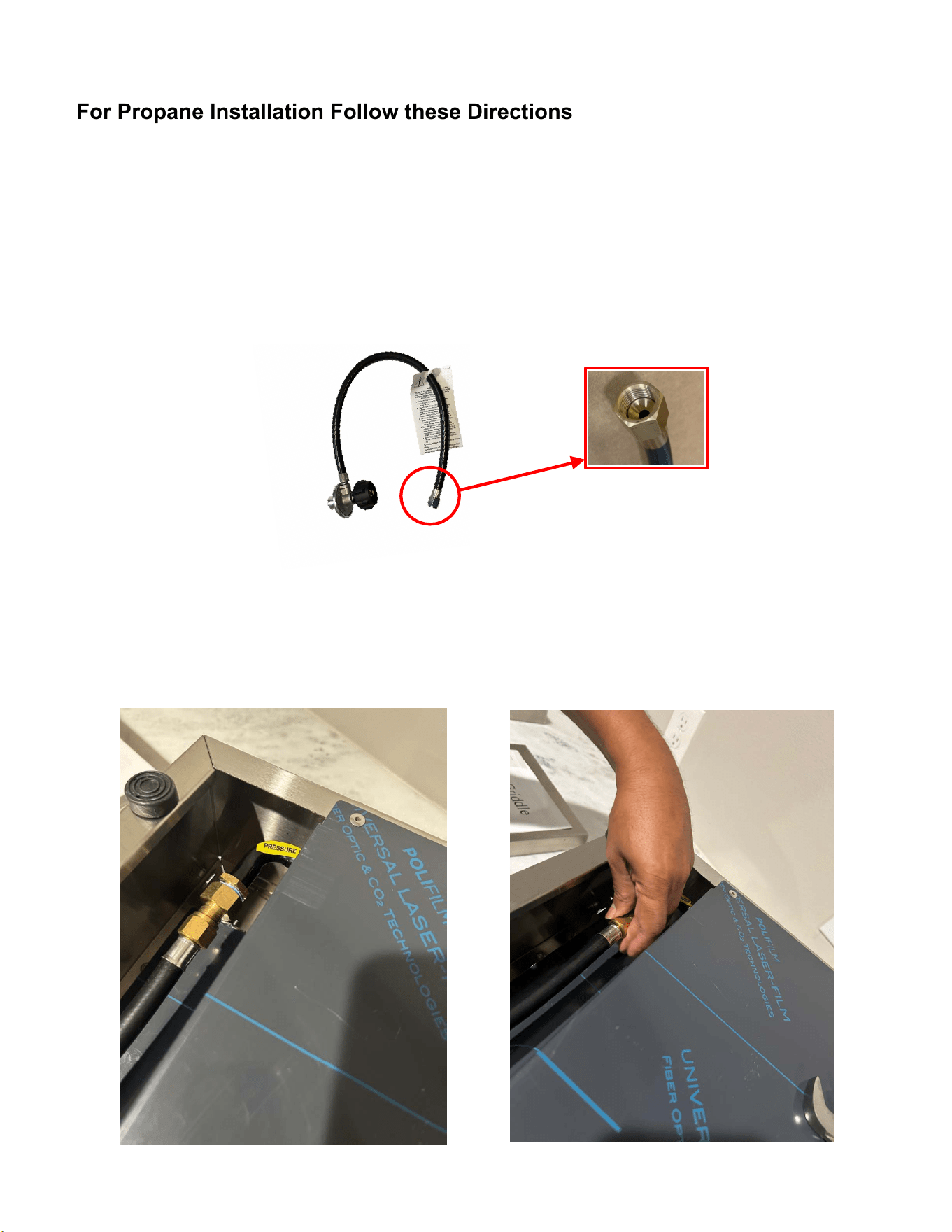
Page 6
Tighten the connection carefully by using 2 properly sized wrenches (7/8" on the
Male gas connection of the unit and 3/4" on the Female connection of the hose).
1. Use the 7/8" wrench on the gas unit connection (Fig. 6).
2. Use the 3/4" wrench on the gas propane hose Female connection (Fig. 7).
3. Hold the 7/8" wrench so the gas unit connection fitting cannot move when
you tighten the Female gas hose connection with 3/4" wrench (Fig. 8).
3.
Fig. 6 Fig. 7 Fig. 8
Connect the propane hose to the propane tank (LP) by following the instructions
supplied with the your pressure regulator and the hose. Make sure your knobs
are in the office position. Turn on your propane tank while the griddle is upside
down to test the gas connections for leaks with soapy water (Fig.9). IF YOU
SEE ANY BUBBLES, TIGHTEN THE CONNECTION FURTHER. IF NOT
RESOLVED CONTACT YOUR DEALER AND DO NOT INSTALL THE UNIT.
4.
Fig. 9
5. Once complete, skip to page 5 for counter top installation.
Note: DO NOT USE pipe sealer, tape, or compounds these not needed for flare connections.
Page 7
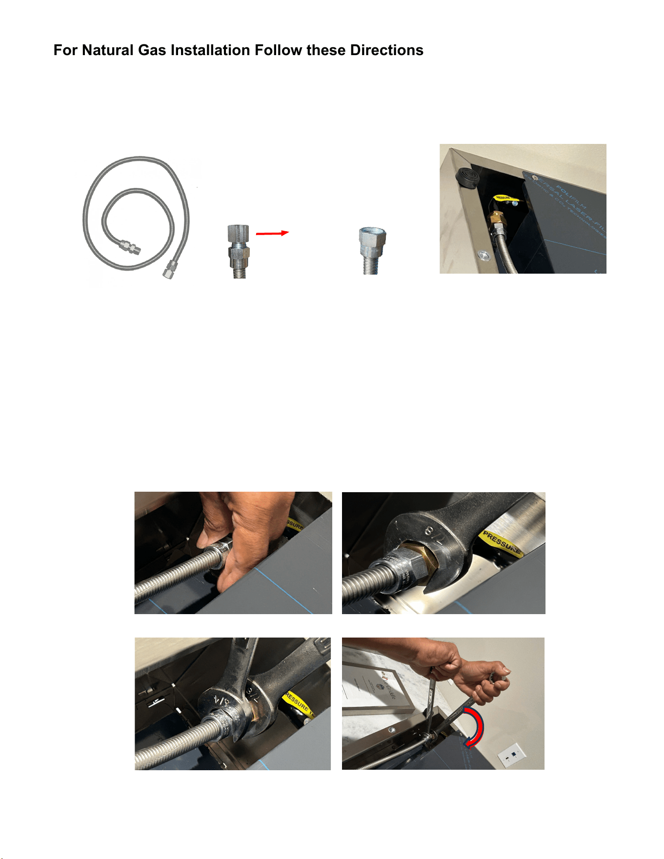
For Natural Gas Installation Follow these Directions
For use with Natural Gas, we recommend using a 3/8" stainless steel flex line (not
included) to connect to the to your low pressure natural gas source (Fig. 10).
These griddles use 7" water column / .25 psi.
3.
Item Number: SSFLEX6436
3/8" Stainless Steel Flex Hose - 36" Long
Item Number: SSFLEX6448
3/8" Stainless Steel Flex Hose - 48" Long
Fig. 10
1. Connect the 3/8" Female flare end of the flex line to the 3/8" Male flare connection
of the unit and screw in a clockwise rotation by hand until it stops (Fig.11).
2. Use the 7/8" wrench on the griddle gas connection (Fig.12).
3. Use the 3/4" wrench on the flex line Female connection (Fig.13).
4. Hold the 7/8" wrench so the griddle gas connection fitting cannot move when you
tighten the female flex line connection with a 3/4" wrench (Fig. 14).
Fig.13 Fig.14
1.
Fig.11 Fig.12
2.
Remove the attached fittings on the end of the flex lines as they are not needed for
this install.
Connect the flex line to the unit:
Remove
Note: DO NOT USE pipe sealer, tape, or compounds these not needed for flare connections.
Page 8
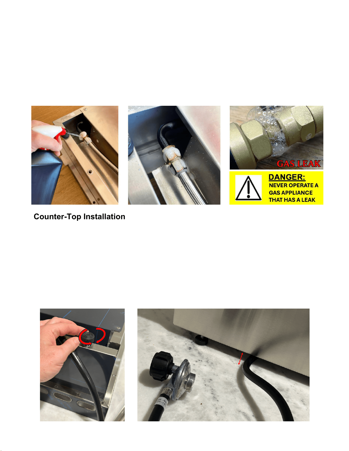
Connect the flex line to the low pressure natural gas source (NG).Check that the
hose is in good condition and replace it if it looks cracked or damaged. The hose
should not be twisted or pulled and should not come into contact with hot parts of
the appliance. Turn on the gas supply and double check if there are any leaks by
applying soapy water to the connection (Fig. 15). IF YOU SEE ANY BUBBLES,
TIGHTEN THE CONNECTION FURTHER. IF NOT RESOLVED CONTACT YOUR
DEALER AND DO NOT INSTALL THE UNIT.
3.
Fig. 15
Fig.16 Fig.17
Counter-Top Installation
Adjust the height of the feet by screwing or unscrewing (Fig. 16) to ensure that
the gas hose or flex line passes between the counter-top and the bottom of the
griddle (Fig. 17). BE CAREFUL THAT THE GAS HOSE IS NEVER CRUSHED.
We recommend passing the gas hose or flex line between the two feet to exit
out the side of the unit. Install the Griddle on a flat surface coated with an
inflammable material (tiles, fire brick, etc.). The distance between the Griddle
and the adjacent walls must be at least 12”.
www.LeGriddleUS.com
Page 9
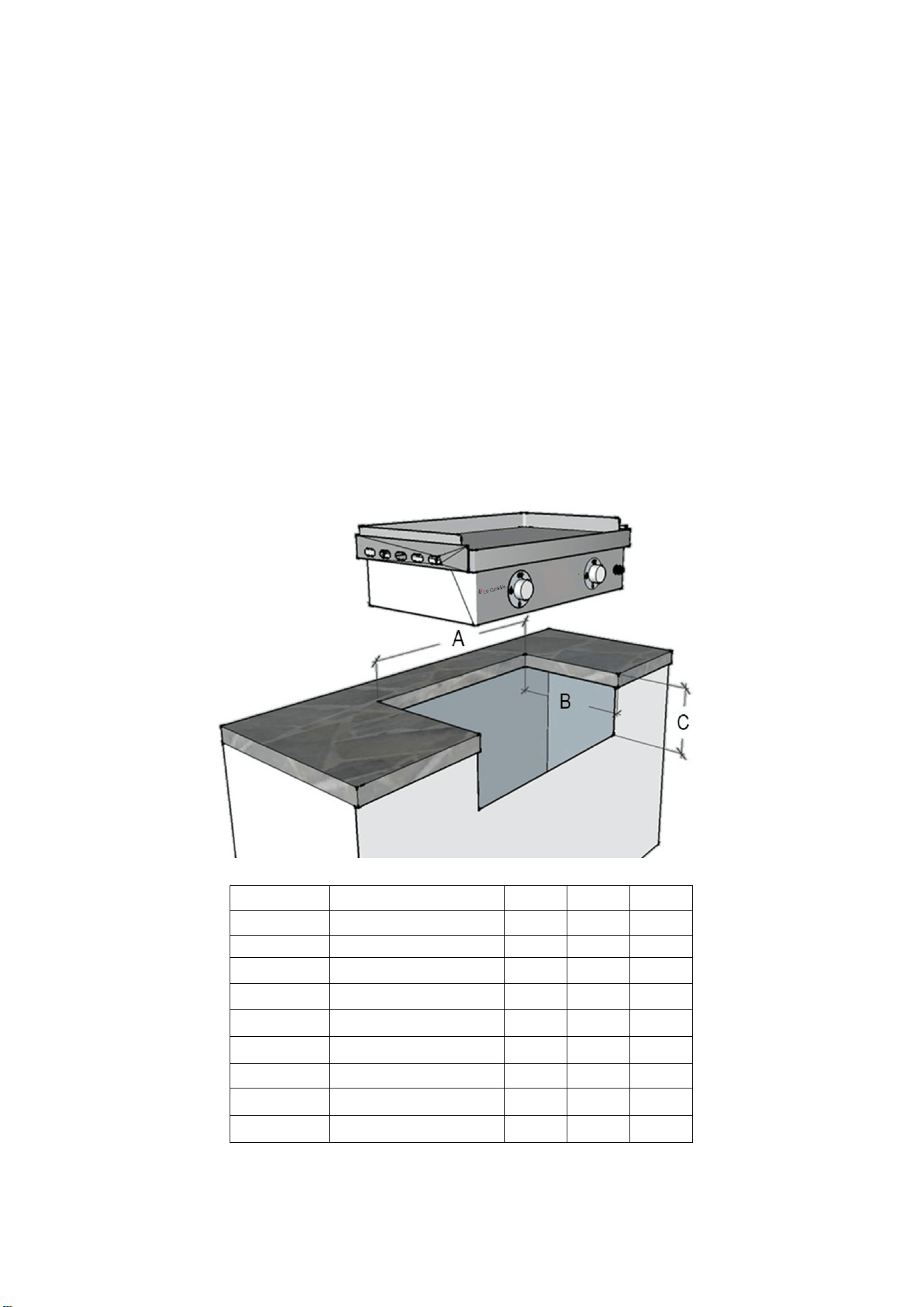
BUILT-IN INSTALLATION:
• Before installing an appliance in any island cut-out, make sure that the opening is not larger than the outside frame of
the appliance unit. The appliance should rest on the lip of the frame. (See cut out recommendations below).
• Pay careful attention to the location of the gas line. It should be routed away from sources of heat, sharp edges, and
aggressive surfaces and should make as few bends as possible. Ensure the gas line connection will be accessible
when the appliance is installed. A safety shutoff valve is required at this gas connection point.
• The underneath of the appliance must be kept well-ventilated to ensure good air circulation to the burner.
• Recommended griddle height: 33 to 37 inches from the ground for a comfortable working position
• The structure must allow a complete air circulation to the griddle and gas cylinder
• Model GFE75 shown below
• If installed in an outdoor kitchen, it must be non-combustible materials or incorporate a liner by Le Griddle.
• Adequate Ventilation: Ensure there is adequate ventilation for both the griddle, cylinder and all appliances located in
this cabinet. Adequate ventilation is required for proper combustion and to prevent gas build up in case there is a leak.
Kitchen vents (RVNT1) are required every 4 feet to help ventilate and prevent potentially dangerous gas build up,
remove excess heat, add air to help with air/fuel mix for the griddles and allows moisture/condensation to evaporate.
• Maintenance Access: When your griddle is installed, you should be able to access the gas supply line including the
gas piping or hose, gas regulator, gas cylinder and any shut off valves. Do not grout or add silicon-in the griddle.
A
B
C
Item
#
Description
Width
Length
Depth
GFE40
16’’ Le Gridde (1 burner)
14
¾”
16
¾”
5
¾”
GFLINER40
16’’
LeGriddle
Liner
17
½”
17
½”
7
¼”
GFE75
30’’ Le Gridde (2 burners)
28
¾”
16
¾”
5
¾”
GFLINER75
30’’ LeGriddle
Liner
31
½”
17
½”
7
¼”
GFE105
41’’ Le Gridde (3 burners)
40
½”
16
¾”
5
¾”
GFLINER105
41’’ LeGriddle
Liner
43”
17
½”
7
¼”
GFE160
61’’ Le Gridde (4 burners)
60
¼”
16
¾”
5
¾”
GFLINER160
61’’ LeGriddle
Liner
62
½”
17
½”
7
¼”
Page 10
* If installing with lid the clearance between the open lid and back-wall must be a minimum of 7".
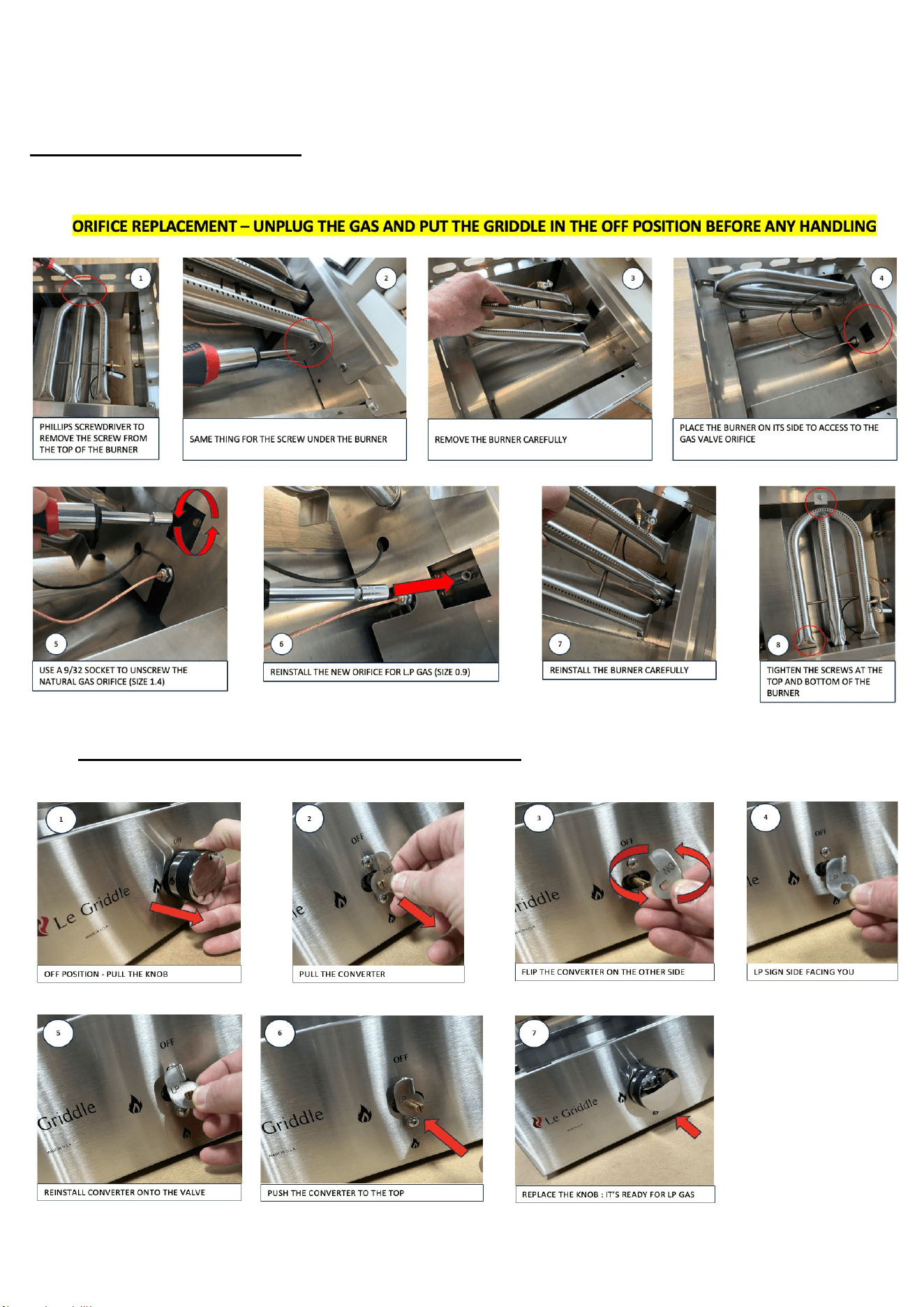
If your new Le Griddle arrives configured to operate on NATURAL GAS (NG). To convert it to LIQUID
PROPANE(LP) please follow these simple steps. The nominal pressure for Natural Gas is 4” water column and 11”
water column for LP gas.
STEP 1 : CHANGE THE ORIFICES
Remove the griddle plate by lifting straight up. Be careful, it is VERY heavy.
STEP 2 : TURN THE CONVERTER FROM NG TO LP
Page 11

Changing the gas tank
• LP cylinder must always be changed with the control knobs in the off position and the valve of
the gas bottle shut.
• LP cylinder must be changed in a well-ventilated place, away from any heat sources (cigarette,
electrical appliance, etc.).
• Always check for gas leaks after every LP cylinder change.
Initial Us
e
Start-Up
1. Once installed, the appliance is ready to use. Make sure the gas valve on the cylinder or gas
supply is turned on. If you smell gas, shut off the gas valve of the NG supply or LP cylinder
and tighten the connections again.
2. Open the lid on your Le Griddle (if supplied)
3. Turn on the Le Griddle valve by turning the control knob to the left, turn the control knob to
the large flame position (drawing on knob).
4. Holding it in this position, push the knob in and press the ignition button until it generates a
spark and lights the burner.
5. Keep the knob depressed for 5 to 10 seconds to trigger the thermocouple safety system.
6. Then release the knob and allow the burner to heat the hot plate to the desired cooking
temperature.
7. Your appliance is now ready to begin cooking.
8. Surface temperatures and cooking times will vary depending on the type of gas used, Natural
or LP, the ambient temperature while cooking outdoors, winds, as well as other factors.
9. Preheat time: 15 min for an outside temperature of 70°F. Increase or reduce this time
depending on the outside temperature by 5 min for 15°F. Medium is the preferred temperature
for preparing most foods.
10. Do not preheat with the lid closed.
11. Do not let the griddle heat without any food on it for more than 30 minutes.
12. Do not use a laser gun to measure the temperature, the stainless steel reflects the beam,
preventing a proper temperature reading. Use a contact thermometer only.
Comments
• The appliance may give off a little smoke or odor the first time it is used; this is perfectly normal.
• Each time the griddle is used, push and turn the knob to the big flame position and hold it down for
2 seconds to allow air to escape, then push the ignition button and hold for 5 more seconds, then
release the knob.
• To view the flame, look through the side of the appliance.
Shutting Down
1.
After use, switch off your appliance, turning the knobs clockwise to the OFF position.
2.
Shut the gas bottle or gas supply valve off.
Cooking: Over time, you will be able to gauge the right cooking temperature and time according
to the thickness and texture of food and adapt it to your taste. For cooking and cleaning videos
and tips, go to LeGriddleUS.com
Page 12

Pro Tips:
-Do not cut food directly on the Le Griddle cooking surface to avoid causing deep scratches.
-Do not leave kitchen utensils on the Griddle, such as cutlery, wooden spoons, plastic utensils, etc.
-Do not overheat the griddle when cooking as this could blacken the plate and make cleaning
difficult.
-The Griddle can also be used to keep food warm after cooking.
Cleaning and maintenance
Important Note: For Locations Near Coastal Areas and Swimming Pools
The stainless-steel materials used in the construction of your griddle are highly rust resistant, however,
chlorine in the air from swimming pools or the salt from sea air may cause surface rust to appear and even
create some pitting if left on the product. Here are a few tips to avoid this: • Regularly wipe down the exterior
surfaces with a damp cloth (micro fiber towels work well, moving with the grain of the stainless) • Allow the
surfaces to dry before installing the cover. Do not cover a damp griddle • In extreme environments apply a
rust inhibitor which leaves a microscopic protective layer on the griddle • For seasonal storage use the
product referred to above, ensure the griddle is dry, then cover and secure the cover to minimize the amount
of damp air getting to the surfaces
The Frame
To avoid any risk of burns, you are advised to always allow the cooking plate to cool down before cleaning
the frame. Clean with a sponge soaked in warm water and detergent. Never use abrasives or steel wire
brushes. (might list what the frame is here so its super clear what to NOT touch)
The Cooking Surface
This is easier to clean when the Griddle is still slightly warm. Beware of the risk of burns. The stainless-steel
plate on the Griddle is shiny before use. The surface is likely to become dull and scratched once utensils
have been used. After a while, the scratches will fade and the plate will have a brushed, weathered look.
After the appliance has been used several times, grease residue may appear on the hot plate; this is perfectly
normal. To remove these, pour a glass of cold water or place ice cubes on the hot plate and scrape off
residue with a spatula or scraper. You can also soak residues in water.
During use, this residue may become detached by themselves; this does not mean that the hot plate has
been damaged. Then pour some water on the hot plate to soak the remaining residue (use a wet sponge or
ice cubes).
With a rigid spatula, remove the water and sticky residue and push it towards the drip tray. Clean with a
scouring pad and then a soft sponge.
Pour some vinegar on the plate to remove smells and strong tastes. Clean the plate promptly after
preparing salty food to avoid any risk of corrosion. Do not use chlorine-based cleaning products as they
can also cause corrosion.
Page 13
The Burners
Check the condition of the flame holes on the burners from time to time. If they are blocked, brush
the holes with a stiff bristled brush. Before using again, wipe the burners thoroughly along with the
base of the Le Griddle. To clean the injectors, you are strongly advised against using metal objects
as these could alter the technical specifications of the burners.
The Drip Tray
It collects juices and crumbs from the griddle surface. You must handle it when it is cold, it must be
emptied and cleaned after each use. It is strongly recommended to remove and clean the tray BEFORE it is
full to the top.
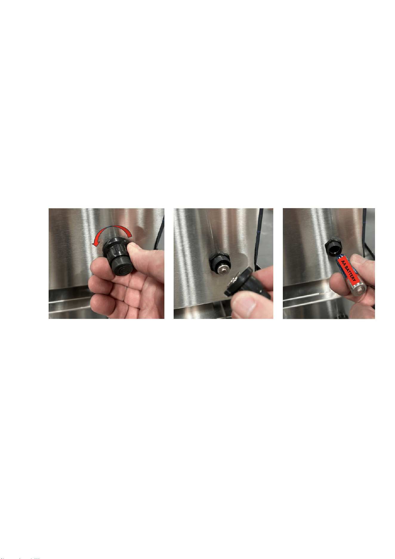
The Igniter
It is provided with a AA (1.5V) battery. To change the battery, unscrew the push-button knob on the front
panel.
Storage
Store your Griddle in a dry, sheltered place where there is no risk of it being damaged. The
optional protective cover must only be used when the Le Griddle is cool.
Page 14

Guarantee and after-sales service.
Industry-leading warranty.
• Lifeti
me against rust through of stainless steel
• Five years for burner rust through
• One year for all other parts
• The guarantee starts from the date of purchase.
We take gr
eat care to ensure that each of our appliances reaches the user in perfect operating
condition. If you do find a problem when unpacking your appliance, please report it to the retailer
within 48 hours. If you notice that the appliance is not working properly during the guarantee
period, please contact your retailer or email us CS@LeGriddleUS.com
The follow
ing are not covered by the guarantee:
• A deformation of the plate can appear when the plate is too hot. This deformation is not
permanent it will disappear when the plate cools and in normal use.
• Normal wear of the product that does not affect operation of the appliance
(scratches, impacts, change of color, etc.).
• The presence of rust, cracks, or other deformation of cast the iron surface is not
detrimental of Le Griddle operation.
• Damage caused by abnormal events or use, modification of the product or not following
the instructions for use (for example, the use of chlorine-based cleaning products).
• Damage resulting from collective use.
• Damage resulting from a fall or impact.
Please do not hesitate to contact us should you have any questions or suggestions at
These gas Le Griddles are manufactured to the specifications of :
-
ANSI Z21.58/CSA 1.6, Outdoor Cooking Gas Appliances, Edition 6, Issue Date 06/2022
-
NSF 4 commercial cooking rethermalization and powered hot food holding and transport equipment, Issue Date 2020
Page 15
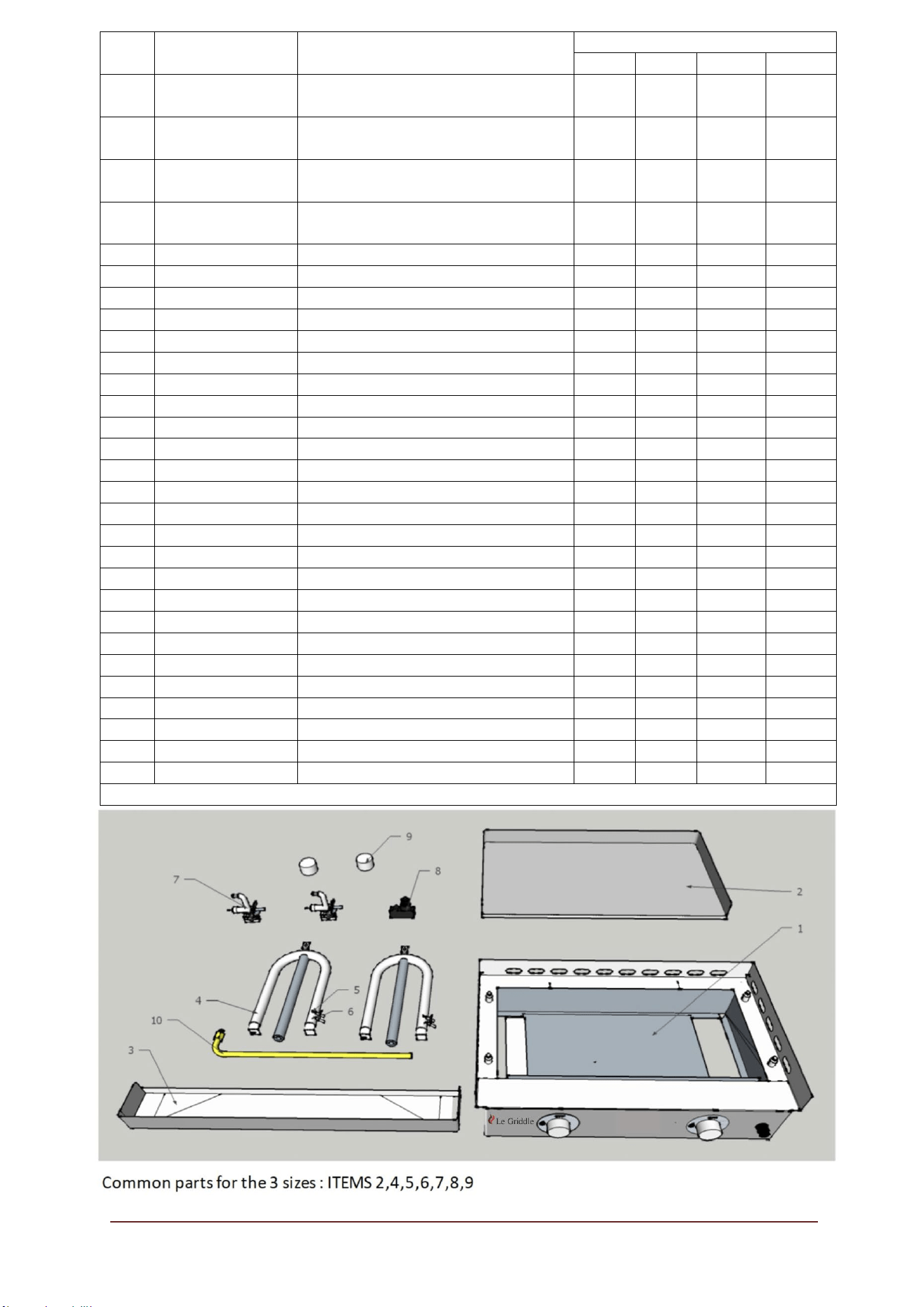
Item
Item
No.
Description
Model
GFE40
GFE75
GFE105
GFE160
1
GRIDDLEGFE40
Body
for
GFE40
(without
equipment 3 to 10)
X
1
GRIDDLEGFE75
Body
for
GFE75
(without
equipment 3 to 10)
X
1
GRIDDLEGFE105
Body
for
GFE105
(without
equipment 3 to 10)
X
1
GRIDDLEGFE160
Body
for
GFE160
(without
equipment 3 to 10)
X
2
GFPLATE40
Cooking Plate for GFE40
X
2
GFPLATE75
Cooking
Plate
for
GFE75
and
GFE160
X
X
2
GFPLATE105
Cooking Plate for GFE40
X
3
GFTANK40
Grease Tank for GFE40
X
3
GFTANK75
Grease
Tank
for
GFE75
and
GFE160
X
X
3
GFTANK105
Grease Tank for GFE105
X
4
GFBURN9000
BURNER
9000
BTU
X
X
X
X
5
GFTHERMO
THERMOCOUPLE
X
X
X
X
6
GFCERAMS
SHORT
IGNITING
WIRE
X
X
6
GFCERAML
LONG
IGNITING
WIRE
X
X
X
6
GFCERAMXL
EXTRA
LONG
IGNITING
WIRE
X
X
X
7
GFVALV
GAS
VALVE
X
X
X
X
8
GF40IGNIT
AA
Electronic
Igniter
1
outlet
X
8
GF75IGNIT
AA
Electronic
Igniter 2
outlet
X
X
8
GF105IGNIT
AA
Electronic
Igniter 3
outlet
X
9
GFKNOB
KNOB
X
X
X
X
10
GFPIPE40
Gas Admission pipe for GFE40
X
10
GFPIPE75
Gas Admission pipe for GFE75
X
10
GFPIPE105
Gas Admission pipe for GFE105
X
10
GFPIPE160
Gas Admission pipe for GFE160
X
11
GFNGORI
Orifice
for
Natural
Gas
140
X
X
X
X
11
GFLPGORI
Orifice for Liquid Propane Gas 90
X
X
X
X
12
GFHAND40
Handle
for
GFLID40
X
12
GFHAND75
Handle
for
GFLID75
X
X
12
GFHAND105
Handle
for
GFLID105
X
For the latest news and product updates, please visit: LeGriddleUS.com
Page 16