
MODULAR HOBS
PLANNING GUIDE
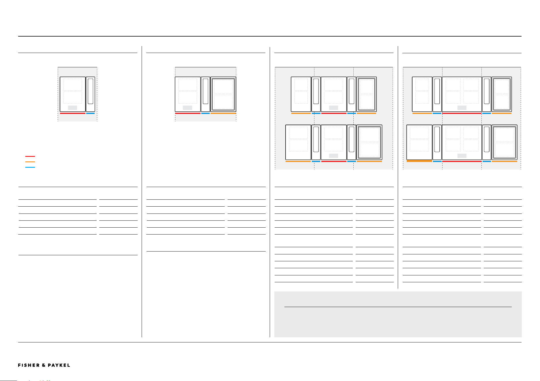
39CM PRIMARY INDUCTION HOB | CI392DTTB1, CI392DTTG1
60CM PRIMARY INDUCTION HOB | CI604DTTB1, CI604DTTG1
76CM PRIMARY INDUCTION HOB | CI764DTTB1, CI764DTTG1
90CM PRIMARY INDUCTION HOB | CI905DTTB1, CI905DTTG1
30CM AUXILIARY INDUCTION HOB | CI302DB1, CI302DG1
39CM AUXILIARY INDUCTION HOB | CI392DB1, CI392DG1
30CM AUXILIARY TEPPANYAKI HOB | CIT302DX1
39CM AUXILIARY TEPPANYAKI HOB | CIT392DX1
13CM MODULAR AUXILIARY DOWNDRAFT EXTRACTOR | CD13DB1, CD13DG1, CD13DB2, CD13DG2
© FISHER & PAYKEL LIMITED 202690003269D EU UK IE PLANNING GUIDE MoDULAR HobS VERSIoN D - MARCH 2026

© FISHER & PAYKEL LIMITED 2026 PAGE 290003269D EU UK IE PLANNING GUIDE MoDULAR HobS VERSIoN D - MARCH 2026
PLANNING GUIDE | MODULAR HOBS
This comprehensive planning guide provides you with the framework and tools to achieve your desired design outcome with Fisher & Paykel appliances. In this guide, you will
find a range of conceptual, detailed, and dimensional product information to bring your ideas to life and create spaces that truly reflect your vision.
Specification Guide 3
System Overview 4
Primary Modules 6
Auxiliary Modules 7
Data Sheets 9
39cm Primary Induction Hob 10
60cm Primary Induction Hob 11
76cm Primary Induction Hob 12
90cm Primary Induction Hob 13
30cm Auxiliary Induction Hob 14
30cm Auxiliary Teppanyaki Hob 15
39cm Auxiliary Induction Hob 16
39cm Auxiliary Teppanyaki Hob 17
13cm Auxiliary Downdraft Overview 18
13cm Auxiliary Downdraft CD13DB1, CD13DG1 19
Supplied Ducting CD13DB1, CD13DG1 21
13cm Auxiliary Downdraft CD13DB2, CD13DG2 22
Supplied Ducting CD13DB2, CD13DG2 24
Auxiliary Downdraft - Recirculation Kit 25
Auxiliary Downdraft - Optional Accessories 27
Product Decisions 28
Modular System Capabilities 29
Modular Ventilation Capabilites 30
Pairing Overview 31
Planning Considerations 32
Installation Overview 33
Installation Planning 34
Typical Configurations with Auxiliary Downdraft 35
Typical Configurations with Overhead Ventilation 36
Benchtop Details 37
Clamping Locations 38
Cabinetry Ventilation 39
Auxiliary Downdraft Components 40
Auxiliary Downdraft Ducting 41
Auxiliary Downdraft System Dimensions 42
Auxiliary Downdraft Venting 43
Electrical Services 44
Modular Connections 46
CONTENTS
CONTENTS
CONCEPT DESIGN PAGE DEVELOPED AND DETAILED DESIGN PAGE DEVELOPED AND DETAILED DESIGN PAGE
IMPORTANT NOTE
DO NOT install the hob directly above a dishwasher, fridge, freezer,
washing machine or clothes dryer, as the humidity may damage
the Hob electronics.
i
i

© FISHER & PAYKEL LIMITED 2026 PAGE 390003269D EU UK IE PLANNING GUIDE MoDULAR HobS - VERSIoN D - MARCH 2026
SPECIFICATION GUIDE
© FISHER & PAYKEL LIMITED 2026 PAGE 490003269D EU UK IE PLANNING GUIDE MoDULAR HobS VERSIoN D - MARCH 2026
The models shown in this Planning Guide may not be available in all markets and are subject to change at any time. Product specifications may vary from those shown. This Planning Guide should not be used as installation guidance for any product. Further information is required to safely and correctly install the
products featured here. Specific installation guidance will be available with the product on delivery and on our website fisherpaykel.com
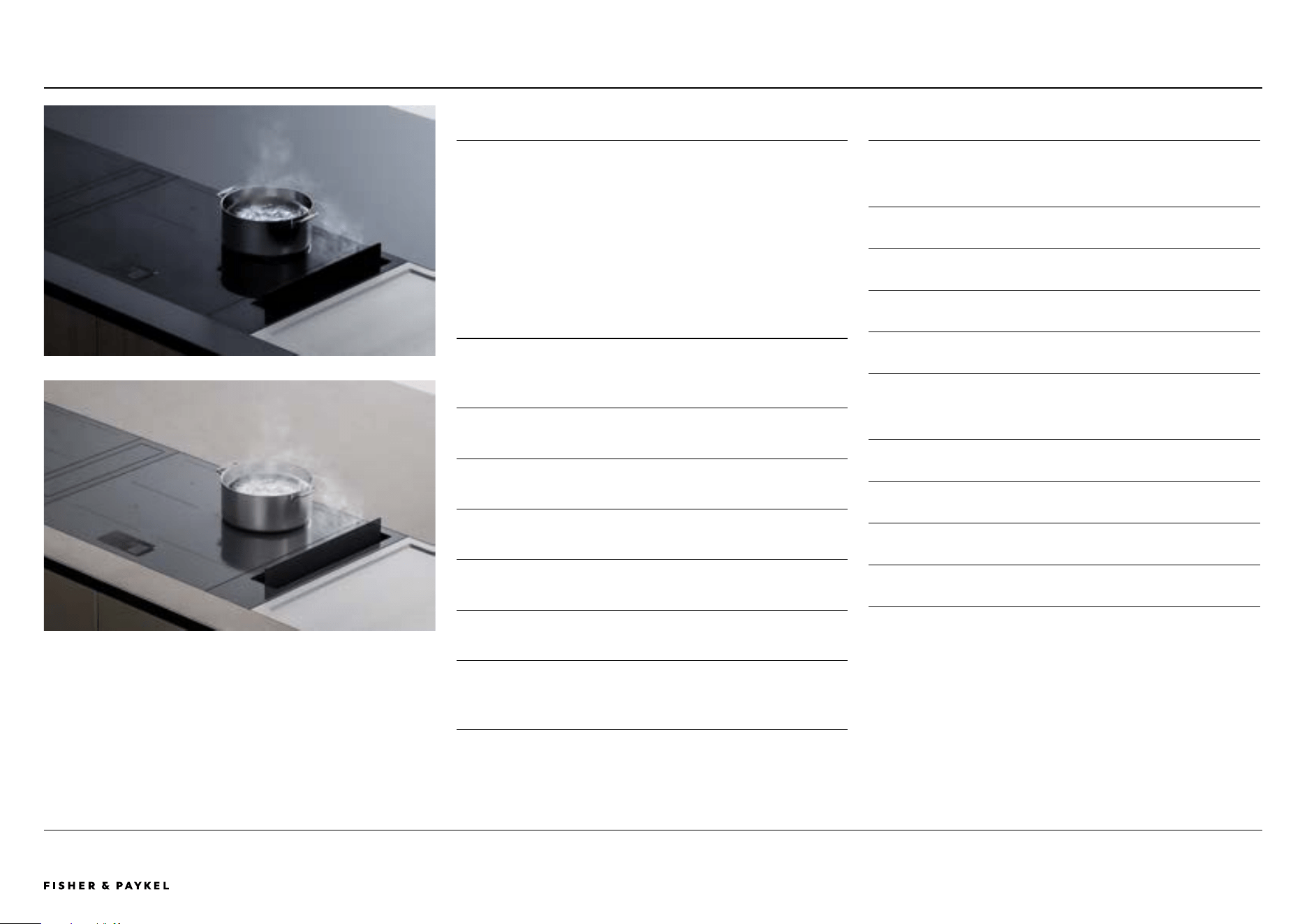
OVERVIEW
Create the ultimate culinary solution with our Series 9 and 11
modular hobs. Using the dierent induction, teppan and
ventilation modules, you can customise the cooking area at the
scale and format best suited to architectural plan and user
needs. Fusing precise induction technology with innovative
design, these modules are crafted to seamlessly work together
for perfect results
FEATURES
1 Tailor the cooking space by pairing primary induction Hob
modules with complementary auxiliary Hobs, downdraft
ventilation and teppan modules.
2 Control the complete modular suite from the primary Hob
using a large intuitive touchscreen.
3 Each module is designed to fit flush or raised with the
countertop for complete design freedom.
4 Choose from a Minimal-style, sleek black glass or subtle grey
glass finish to suit your kitchen design.
5 SmartHQ™ app connectivity to monitor cook
status and product.
6 Wireless Temperature Sensor precisely monitors and controls
cooking in real time, for complete control.*
7 Poach, Sous Vide and other Cook by Method functions
are available on product, when using the Wireless
Temperature Sensor.
* Selected models only.
PRODUCT OVERVIEW
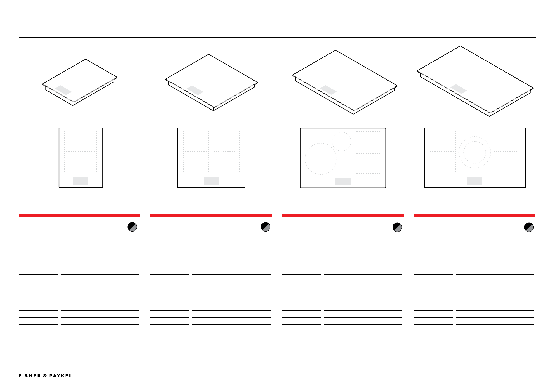
PRIMARY MoDULAR INDUCTIoN HobS
With touchscreen user interface
CI392DTTb1 (black), CI392DTTG1 (Grey)
39cm Primary Induction Hob, 2 Zones with SmartZone
CI604DTTb1 (black), CI604DTTG1 (Grey)
60cm Primary Induction Hob, 4 Zones with SmartZone
CI764DTTb1 (black), CI764DTTG1 (Grey)
76cm Primary Induction Hob, 4 Zones with SmartZone
CI905DTTb1 (black), CI905DTTG1 (Grey)
90cm Primary Induction Hob, 5 Zones with SmartZone
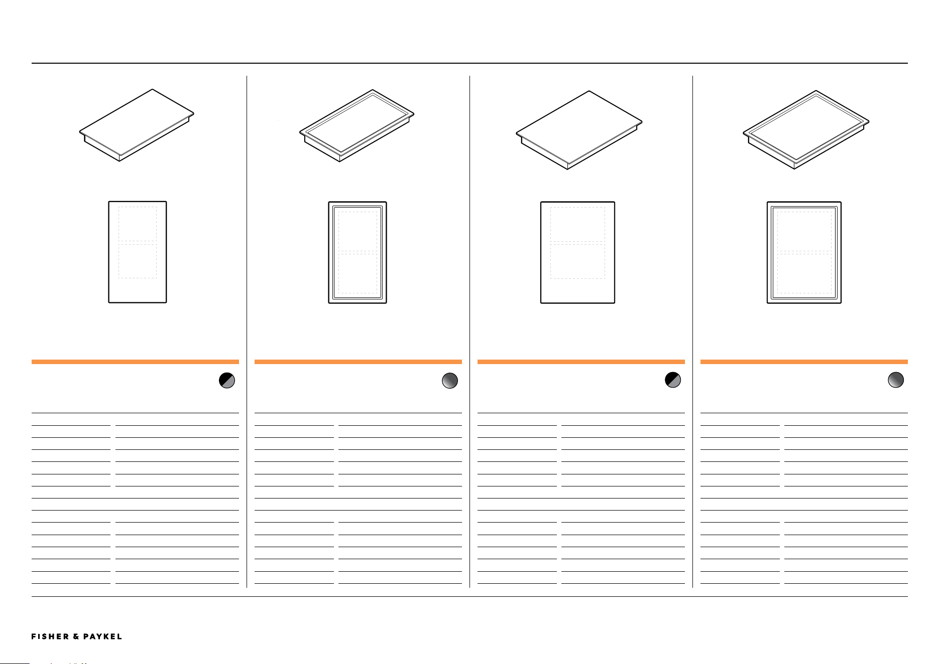
AUXILIARY MoDULAR HobS
No user interface. Controlled via paired primary hob.
CI302Db1 (black), CI302DG1 (Grey)
30cm Auxiliary Induction Hob, 2 Zones with SmartZone
CI392Db1 (black), CI392DG1 (Grey)
39cm Auxiliary Induction Hob, 2 Zones with SmartZone
CIT302DX1
30cm Auxiliary Teppanyaki Hob, 2 Zones
CIT392DX1
39cm Auxiliary Teppanyaki Hob, 2 Zones
SPECIFICATION GUIDE | MODULAR HOBS
<< CONTENTS
© FISHER & PAYKEL LIMITED 2026 PAGE 590003269D EU UK IE PLANNING GUIDE MoDULAR HobS VERSIoN D - MARCH 2026
The models shown in this Planning Guide may not be available in all markets and are subject to change at any time. Product specifications may vary from those shown. This Planning Guide should not be used as installation guidance for any product. Further information is required to safely and correctly install the
products featured here. Specific installation guidance will be available with the product on delivery and on our website fisherpaykel.com
PRODUCT OVERVIEW CONTINUED
AUXILIARY MoDULAR VENTILATIoN
No user interface. Controlled via paired primary hob.
CD13Db1 (black), CD13DG1 (Grey)*
13cm Modular Auxiliary Downdraft Extractor, 300x70
CD13Db2 (black), CD13DG2 (Grey)*
13cm Modular Auxiliary Downdraft Extractor, 222x89
* Please contact the Fisher & Paykel design support team
designsupport@fisherpaykel.com for Modular Auxiliary Downdraft
product availability.
ACCESSoRIES
WTSC1
Wireless Temperature Sensor (1x included per Primary
Induction Cob. Also available to purchase separately).
KRCID834
Recirculation Kit
Ducting
A full range of ducting components are available (1x set
included per Modular Auxilliary Dowdraft, see data sheet for
component list. Also available to purchase separately)
SPECIFICATION GUIDE | MODULAR HOBS
<< CONTENTS
© FISHER & PAYKEL LIMITED 2026 PAGE 690003269D EU UK IE PLANNING GUIDE MoDULAR HobS VERSIoN D - MARCH 2026 PAGE 690003269D EU UK IE PLANNING GUIDE MoDULAR HobS VERSIoN D - MARCH 2026
The models shown in this Planning Guide may not be available in all markets and are subject to change at any time. Product specifications may vary from those shown. This Planning Guide should not be used as installation guidance for any product. Further information is required to safely and correctly install the
products featured here. Specific installation guidance will be available with the product on delivery and on our website fisherpaykel.com
PRIMARY MODULES
39CM PRIMARY INDUCTION HOB, 2 ZONES WITH SMARTZONE
Model no:
CI392DTTB1 Black
CI392DTTG1 Grey
Dimensions
W x D x H
Product
385 x 530 x 62
Glass
385 x 530 x 6
Cutout, proud
347 x 507
Cutout, flush
347 x 509
Recess, flush
389 x 534 x 6.5
Power Requirements
Supply
220-240 V, 50 Hz / 60 Hz
Service
16 A
Connection
Power cord, stripped ends, 1 N
Power Cable
1700 mm
Weight 8 kg
60CM PRIMARY INDUCTION HOB, 4 ZONES WITH SMARTZONE
Model no:
CI604DTTB1 Black
CI604DTTG1 Grey
Dimensions W x D x H
Product
600 x 530 x 62
Glass 600 x 530 x 6
Cutout, proud 562 x 507
Cutout, flush 562 x 509
Recess, flush 604 x 534 x 6.5
Power Requirements
Supply
220-240 V, 50 Hz / 60 Hz
Service
32 A
Connection
Terminal block, 1 N or 2 N
Power Cable
not supplied
Weight 14 kg
76CM PRIMARY INDUCTION HOB, 4 ZONES WITH SMARTZONE
Model no:
CI764DTTB1 Black
CI764DTTG1 Grey
Dimensions
W x D x H
Product
760 x 530 x 62
Glass
760 x 530 x 6
Cutout, proud
722 x 507
Cutout, flush
722 x 509
Recess, flush
764 x 534 x 6.5
Power Requirements
Supply
220-240 V, 50 Hz / 60 Hz
Service
32 A
Connection
Terminal block, 1 N or 2 N
Power Cable
not supplied
Weight
16 kg
90CM PRIMARY INDUCTION HOB, 5 ZONES WITH SMARTZONE
Model no:
CI905DTTB1 Black
CI905DTTG1 Grey
Dimensions
W x D x H
Product
900 x 530 x 62
Glass
900 x 530 x 6
Cutout, proud
862 x 507
Cutout, flush
862 x 509
Recess, flush
904 x 534 x 6.5
Power Requirements
Supply
220-240 V, 50 Hz / 60 Hz
Service
48 A
Connection
Terminal block, 1 N or 3 N
Power Cable
not supplied
Weight
20 kg
PRODUCT SPECIFICATIONS | MODULAR HOBS
<< CONTENTS
© FISHER & PAYKEL LIMITED 2026 PAGE 790003269D EU UK IE PLANNING GUIDE MoDULAR HobS VERSIoN D - MARCH 2026 PAGE 790003269D EU UK IE PLANNING GUIDE MoDULAR HobS VERSIoN D - MARCH 2026
The models shown in this Planning Guide may not be available in all markets and are subject to change at any time. Product specifications may vary from those shown. This Planning Guide should not be used as installation guidance for any product. Further information is required to safely and correctly install the
products featured here. Specific installation guidance will be available with the product on delivery and on our website fisherpaykel.com
AUXILIARY MODULES
30CM AUXILIARY INDUCTION HOB, 2 ZONES WITH SMARTZONE
Model no:
CI302DB1 Black
CI302DG1 Grey
Dimensions
W x D x H
Product
300 x 530 x 62
Glass 300 x 530 x 6
Cutout, proud 262 x 507
Cutout, flush 262 x 509
Recess, flush 304 x 534 x 6.5
Power Requirements
Supply
220-240 V, 50 Hz / 60 Hz
Service
16 A
Connection
Power cord, stripped ends, 1 N
Power Cable
1700 mm
Weight 7 kg
39CM AUXILIARY INDUCTION HOB, 2 ZONES WITH SMARTZONE
Model no:
CI392DB1 Black
CI392DG1 Grey
Dimensions
W x D x H
Product
385 x 530 x 62
Glass
385 x 530 x 6
Cutout, proud
347 x 507
Cutout, flush
347 x 509
Recess, flush
389 x 534 x 6.5
Power Requirements
Supply
220-240 V, 50 Hz / 60 Hz
Service
16 A
Connection
Power cord, stripped ends, 1 N
Power Cable
1700 mm
Weight
8 kg
39CM AUXILIARY TEPPANYAKI HOB 2 ZONES
Model no:
CIT392DX1
Dimensions
W x D x H
Product
385 x 530 x 74
Plate
385 x 530 x 6
Cutout, proud
347 x 507
Cutout, flush
347 x 509
Recess, flush
389 x 534 x 6.5
Power Requirements
Supply
220-240 V, 50 Hz / 60 Hz
Service
12 A
Connection
Power cord, stripped ends, 1 N
Power Cable
1700 mm
Weight
15 kg
30CM AUXILIARY TEPPANYAKI HOB, 2 ZONES
Model no:
CIT302DX1
Dimensions
W x D x H
Product
300 x 530 x 74
Plate
300 x 530 x 6
Cutout, proud
262 x 507
Cutout, flush
262 x 509
Recess, flush
304 x 534 x 6.5
Power Requirements
Supply
220-240 V, 50 Hz / 60 Hz
Service
12 A
Connection
Power cord, stripped ends, 1 N
Power Cable
1700 mm
Weight
12 kg
PRODUCT SPECIFICATIONS | MODULAR HOBS
<< CONTENTS
© FISHER & PAYKEL LIMITED 2026 PAGE 890003269D EU UK IE PLANNING GUIDE MoDULAR HobS VERSIoN D - MARCH 2026 PAGE 890003269D EU UK IE PLANNING GUIDE MoDULAR HobS VERSIoN D - MARCH 2026
The models shown in this Planning Guide may not be available in all markets and are subject to change at any time. Product specifications may vary from those shown. This Planning Guide should not be used as installation guidance for any product. Further information is required to safely and correctly install the
products featured here. Specific installation guidance will be available with the product on delivery and on our website fisherpaykel.com
AUXILIARY MODULES
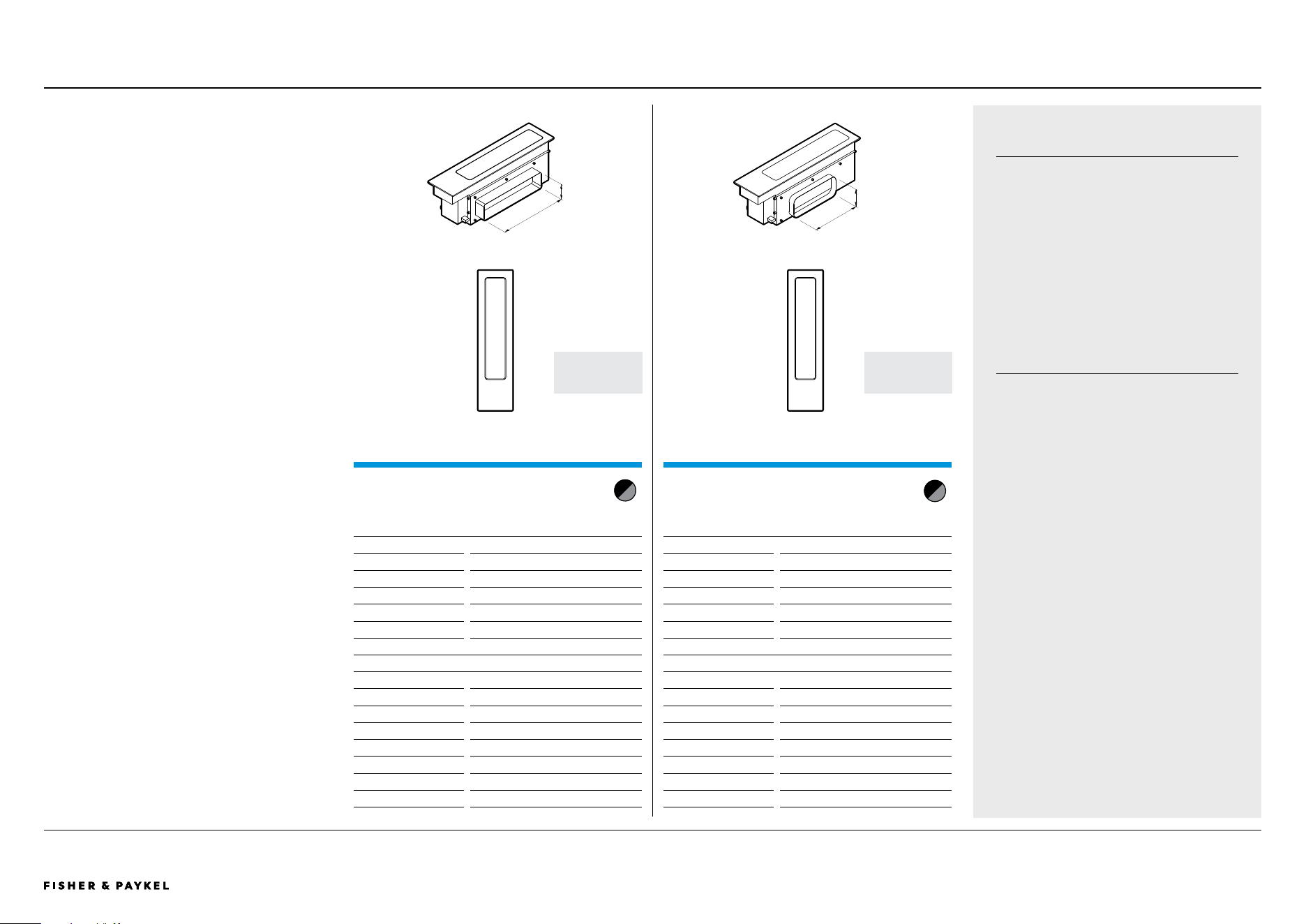
13CM MODULAR AUXILIARY DOWNDRAFT EXTRACTOR, 300X70
Model no:
CD13DB1 Black
CD13DG1 Grey
Dimensions
W x D x H
Product
130 x 530 x 186
Glass
130 x 530 x 6
Cutout, proud**
98 x 507
Cutout, flush**
98 x 509
Recess, flush**
134 x 534 x 6.5
Power Requirements
Supply
220-240 V, 50 Hz
Service
5 A
Connection
Power cord, plug
Power Cable
3000 mm
Weight
3kg
Ducting
300 x 70
** Must be installed in combined cutout with Hob
PRODUCT SPECIFICATIONS | MODULAR HOBS
ELECTRICAL SERVICE FOR MULTIPLE
PRODUCT INSTALLS
Where multiple products are being installed
together, it is possible to use a smaller local
distribution board, rather than running
multiple separate lines. For example, 2 x 15A
modules can be connected via a single 30A
breaker.
These cooktops must only be connected to
the mains power supply by a suitably
qualified person.
PRODUCT AVAILABILTIY
Please contact the Fisher & Paykel design
support team
designsupport@fisherpaykel.com
for Auxiliary Modular Downdraft Extractor
model availability.
13CM MODULAR AUXILIARY DOWNDRAFT EXTRACTOR, 222X89
Model no:
CD13DB2 Black
CD13DG2 Grey
Dimensions
W x D x H
Product
130 x 530 x 186
Glass
130 x 530 x 6
Cutout, proud**
98 x 507
Cutout, flush**
98 x 509
Recess, flush**
134 x 534 x 6.5
Power Requirements
Supply
220-240 V, 50 Hz
Service
5 A
Connection
Power cord, plug
Power Cable
3000 mm
Weight
3kg
Ducting
222 x 89
** Must be installed in combined cutout with Hob
CHECK
AVAILABILITY
CHECK
AVAILABILITY
300
70
222
89
<< CONTENTS

© FISHER & PAYKEL LIMITED 2026 PAGE 990003269D EU UK IE PLANNING GUIDE MoDULAR HobS - VERSIoN D - MARCH 2026
DATA SHEETS
© FISHER & PAYKEL LIMITED 2026 PAGE 1090003269D EU UK IE PLANNING GUIDE MoDULAR HobS VERSIoN D - MARCH 2026 PAGE 1090003269D EU UK IE PLANNING GUIDE MoDULAR HobS VERSIoN D - MARCH 2026
IMPORTANT NOTE: Throughout this guide, dimensions may vary by ±2mm (1/16''). Please
read the installation manual for detailed information on installing the product. For full
installation instructions & specifications visit fisherpaykel.com
INDICATES CABINETRY / PRODUCT DATUM ---------------------------------
INDICATES CABINETRY CLEARANCES ----------------------------------------
INDICATES CUTOUT ---------------------------------------------------------------
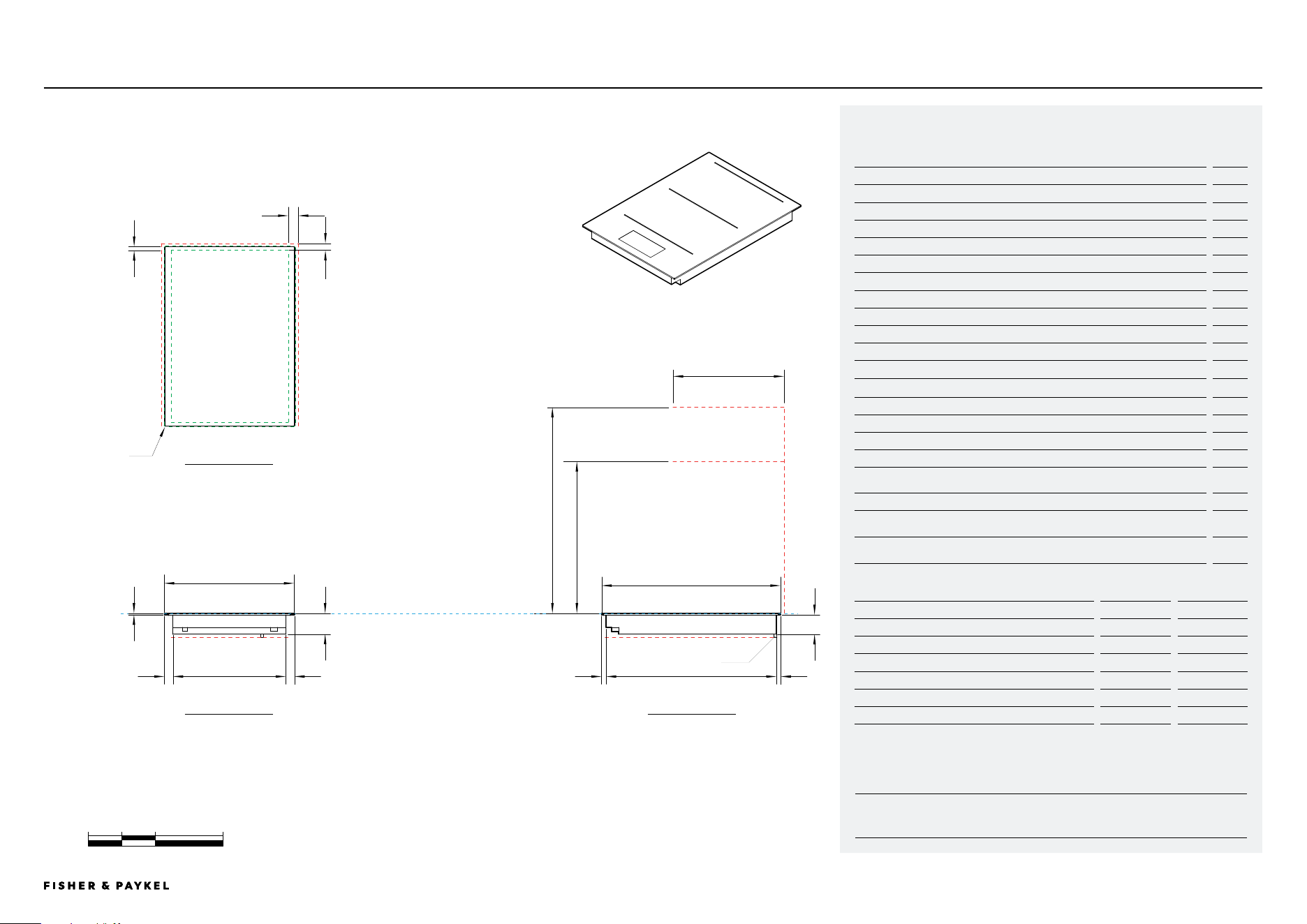
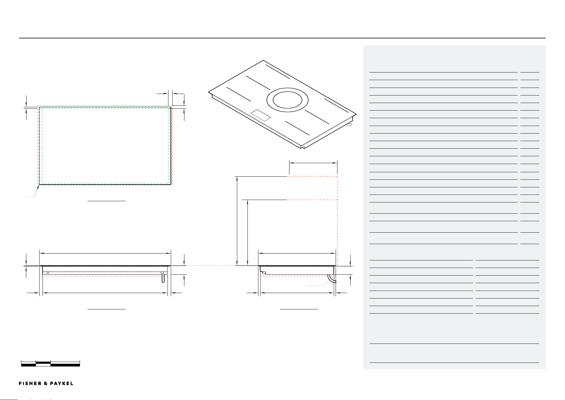
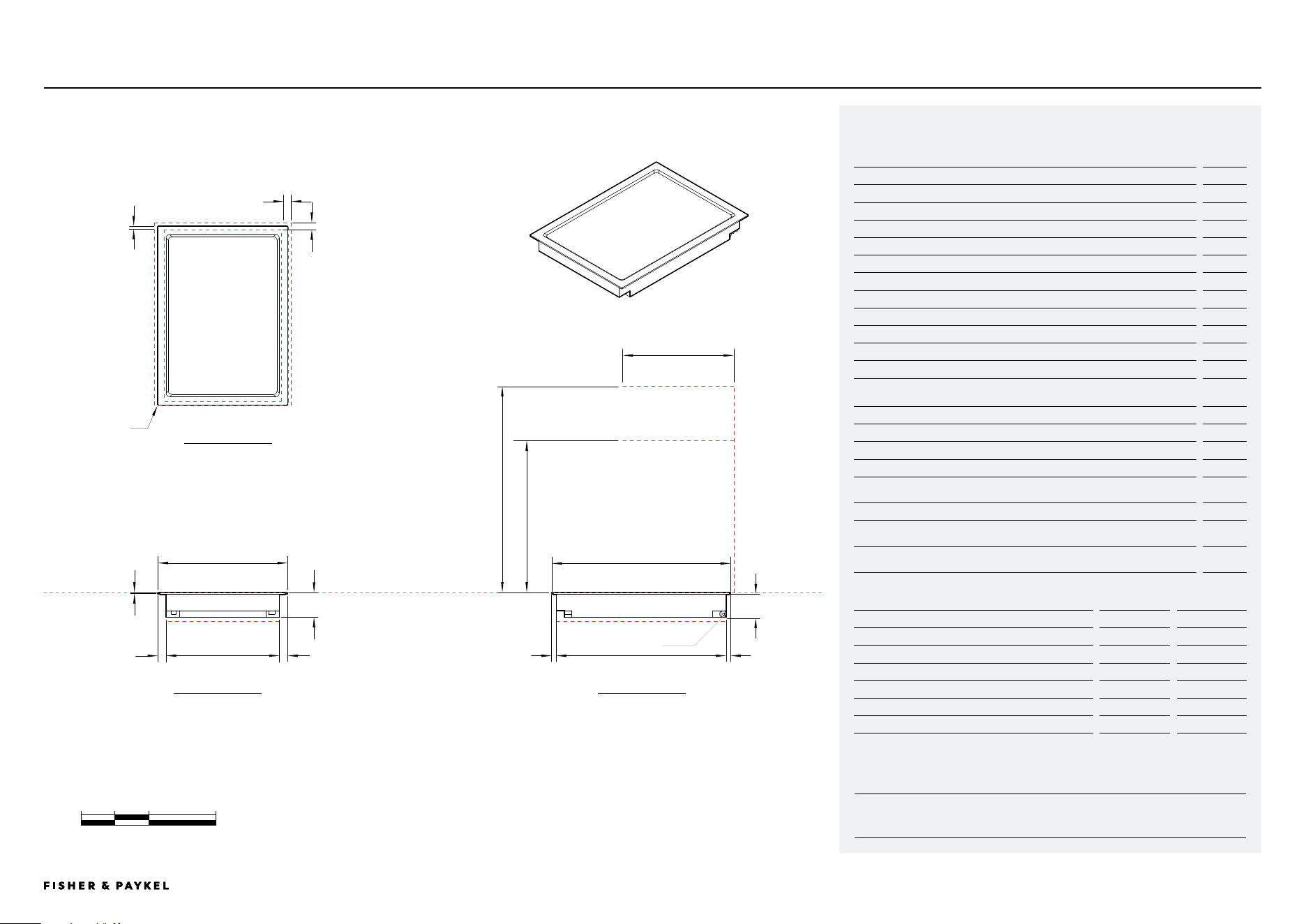
CI392DTTB1, CI392DTTG1
0 100 200 400
millimetres
Model no:
39cm Primary Induction Hob, 2 Zones with SmartZone, Black - CI392DTTB1,
39cm Primary Induction Hob, 2 Zones with SmartZone, Grey - CI392DTTG1
Product Dimensions
mm
A Overall height of Hob
62
B Overall width of Hob
385
C Overall depth of Hob
530
D Height of Hob glass (includes flange and tape)
6
E Corner radius of glass
2
F Height of chassis
56
G Width of chassis
334
H Depth of chassis
504
I Width from side edges of Hob to chassis
25.5
J Depth from front edge of Hob to chassis
13.5
K Depth from back edge of Hob to chassis
12.5
Product Clearances
mm
L Minimum clearance from side edges of cutout to nearest combustible surface
29
M Minimum clearance from rear edge of cutout to nearest combustible surface
21
N Minimum clearance from cook surface to cooker hood or overhead cabinet
610
O Minimum clearance from cook surface to overhead cabinet not
directly above Hob
450
P Maximum depth of overhead cabinetry
330
Minimum ventilation gap between bottom of benchtop and top of cabinetry fronts
(not shown)
4
Minimum clearance from cook surface to top of any appliances, companion
product or obstruction below Hob
72
NOTE: The oven installed below the Hob MUST have a cooling fan. It is important that the induction Hob receives
adequate air supply. For ventilation requirements please refer to the installation manual.
Cutout Dimensions*
Proud mm
Flush mm
Overall width of cutout
347
347
Overall depth of cutout
507
509
Overall width of recess
-
389
Overall depth of recess
-
534
Overall height of recess
-
6.5
Recess corner radius
-
4
*Note cutout position is centred to the Hob.
DATA SHEETS | MODULAR HOBS
K
L
e
m
d
i
a
ig
n o
j
f
k
h
p
CLEARANCE: COOKER HOOD,
OVERHEAD CABINET
CLEARANCE: OVERHEAD
CABINET NOT DIRECTLY ABOVE
CLEARANCE: BELOW HOBCLEARANCE: BELOW HOB
DATUM: TOP OF COOKSURFACE
CLEARANCE: COMBUSTIBLE SURFACE
CLEARANCE: COMBUSTIBLE SURFACE
b
385
c
530
POWER OUTLET
PRoFILE VIEW
FRoNT VIEW
PLAN VIEW
<< CONTENTS
© FISHER & PAYKEL LIMITED 2026 PAGE 1190003269D EU UK IE PLANNING GUIDE MoDULAR HobS VERSIoN D - MARCH 2026 PAGE 1190003269D EU UK IE PLANNING GUIDE MoDULAR HobS VERSIoN D - MARCH 2026
IMPORTANT NOTE: Throughout this guide, dimensions may vary by ±2mm (1/16''). Please
read the installation manual for detailed information on installing the product. For full
installation instructions & specifications visit fisherpaykel.com
INDICATES CABINETRY / PRODUCT DATUM ---------------------------------
INDICATES CABINETRY CLEARANCES ----------------------------------------
INDICATES CUTOUT ---------------------------------------------------------------
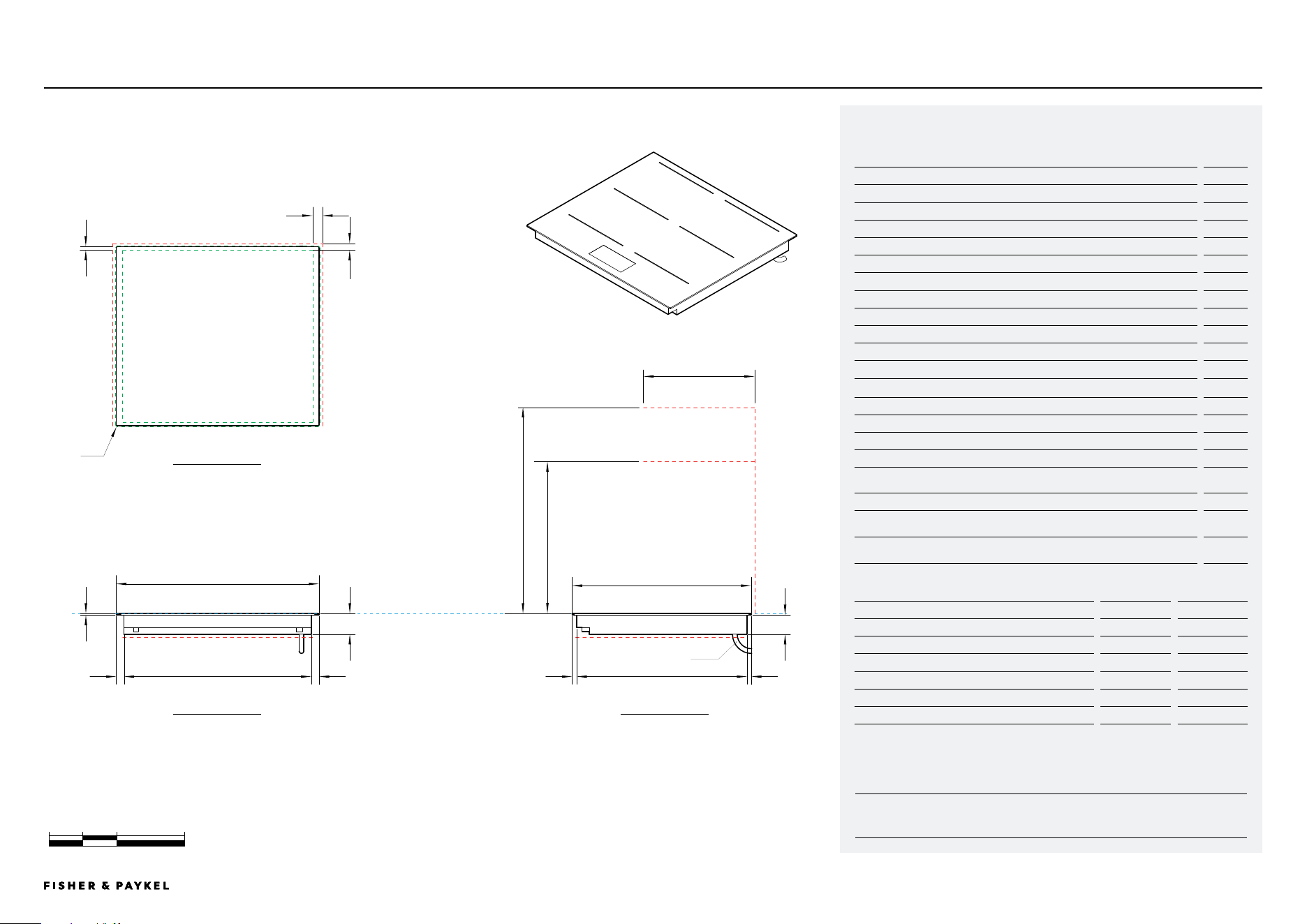
CI604DTTB1, CI604DTTG1
0 100 200 400
millimetres
Model no:
60cm Primary Induction Hob, 4 Zones with SmartZone, Black - CI604DTTB1,
60cm Primary Induction Hob, 4 Zones with SmartZone, Grey - CI604DTTG1
Product Dimensions
mm
A Overall height of Hob
62
B Overall width of Hob
600
C Overall depth of Hob
530
D Height of Hob glass (includes flange and tape)
6
E Corner radius of glass
2
F Height of chassis
56
G Width of chassis
554
H Depth of chassis
504
I Width from side edges of Hob to chassis
23
J Depth from front edge of Hob to chassis
13.5
K Depth from back edge of Hob to chassis
12.5
Product Clearances
mm
L Minimum clearance from side edges of cutout to nearest combustible surface
29
M Minimum clearance from rear edge of cutout to nearest combustible surface
21
N Minimum clearance from cook surface to cooker hood or overhead cabinet
610
O Minimum clearance from cook surface to overhead cabinet not
directly above Hob
450
P Maximum depth of overhead cabinetry
330
Minimum ventilation gap between bottom of benchtop and top of cabinetry
fronts (not shown)
4
Minimum clearance from cook surface to top of any appliances, companion
product or obstruction below Hob
72
NOTE: The oven installed below the Hob MUST have a cooling fan. It is important that the induction Hob receives
adequate air supply. For ventilation requirements please refer to the installation manual.
Cutout Dimensions*
Proud mm
Flush mm
Overall width of cutout
562
562
Overall depth of cutout
507
509
Overall width of recess
-
604
Overall depth of recess
-
534
Overall height of recess
-
6.5
Recess corner radius
-
4
*Note cutout position is centred to the Hob.
DATA SHEETS | MODULAR HOBS
K
L
e
m
d
i
a
i
g
n o
j
f
k
h
p
CLEARANCE: COOKER HOOD,
OVERHEAD CABINET
CLEARANCE: OVERHEAD
CABINET NOT DIRECTLY ABOVE
CLEARANCE: BELOW HOB
CLEARANCE: BELOW HOB
DATUM: TOP OF COOKSURFACE
CLEARANCE: COMBUSTIBLE SURFACE
CLEARANCE: COMBUSTIBLE SURFACE
b
385
c
530
POWER OUTLET
PRoFILE VIEW
FRoNT VIEW
PLAN VIEW
<< CONTENTS
© FISHER & PAYKEL LIMITED 2026 PAGE 1290003269D EU UK IE PLANNING GUIDE MoDULAR HobS VERSIoN D - MARCH 2026 PAGE 1290003269D EU UK IE PLANNING GUIDE MoDULAR HobS VERSIoN D - MARCH 2026
IMPORTANT NOTE: Throughout this guide, dimensions may vary by ±2mm (1/16''). Please
read the installation manual for detailed information on installing the product. For full
installation instructions & specifications visit fisherpaykel.com
INDICATES CABINETRY / PRODUCT DATUM ---------------------------------
INDICATES CABINETRY CLEARANCES ----------------------------------------
INDICATES CUTOUT ---------------------------------------------------------------
CI764DTTB1, CI764DTTG1
0 100 200 400
millimetres
Model no:
76cm Primary Induction Hob, 4 Zones with SmartZone, Black - CI764DTTB1,
76cm Primary Induction Hob, 4 Zones with SmartZone, Grey - CI764DTTG1
Product Dimensions
mm
A Overall height of Hob
62
B Overall width of Hob
760
C Overall depth of Hob
530
D Height of Hob glass (includes flange and tape)
6
E Corner radius of glass
2
F Height of chassis
56
G Width of chassis
714
H Depth of chassis
504
I Width from side edges of Hob to chassis
23
J Depth from front edge of Hob to chassis
13.5
K Depth from back edge of Hob to chassis
12.5
Product Clearances
mm
L Minimum clearance from side edges of cutout to nearest combustible surface
29
M Minimum clearance from rear edge of cutout to nearest combustible surface
21
N Minimum clearance from cook surface to cooker hood or overhead cabinet
610
O Minimum clearance from cook surface to overhead cabinet not
directly above Hob
450
P Maximum depth of overhead cabinetry
330
Minimum ventilation gap between bottom of benchtop and top of cabinetry
fronts (not shown)
4
Minimum clearance from cook surface to top of any appliances, companion
product or obstruction below Hob
72
NOTE: The oven installed below the Hob MUST have a cooling fan. It is important that the induction Hob receives
adequate air supply. For ventilation requirements please refer to the installation manual.
Cutout Dimensions*
Proud mm
Flush mm
Overall width of cutout
722
722
Overall depth of cutout
507
509
Overall width of recess
-
764
Overall depth of recess
-
534
Overall height of recess
-
6.5
Recess corner radius
-
4
*Note cutout position is centred to the Hob.
DATA SHEETS | MODULAR HOBS
K
L
e
m
d
i
a
i
g
n o
j
f
k
h
p
CLEARANCE: COOKER HOOD,
OVERHEAD CABINET
CLEARANCE: OVERHEAD
CABINET NOT DIRECTLY
ABOVE
CLEARANCE: BELOW HOB
CLEARANCE: BELOW HOB
DATUM: TOP OF COOKSURFACE
CLEARANCE: COMBUSTIBLE SURFACE
CLEARANCE: COMBUSTIBLE SURFACE
b
385
c
530
POWER OUTLET
PRoFILE VIEW
FRoNT VIEW
PLAN VIEW
<< CONTENTS
© FISHER & PAYKEL LIMITED 2026 PAGE 1390003269D EU UK IE PLANNING GUIDE MoDULAR HobS VERSIoN D - MARCH 2026 PAGE 1390003269D EU UK IE PLANNING GUIDE MoDULAR HobS VERSIoN D - MARCH 2026
IMPORTANT NOTE: Throughout this guide, dimensions may vary by ±2mm (1/16''). Please
read the installation manual for detailed information on installing the product. For full
installation instructions & specifications visit fisherpaykel.com
INDICATES CABINETRY / PRODUCT DATUM ---------------------------------
INDICATES CABINETRY CLEARANCES ----------------------------------------
INDICATES CUTOUT ---------------------------------------------------------------
0 100 200 400
millimetres
CI905DTTB1, CI905DTTG1
Model no:
90cm Primary Induction Hob, 5 Zones with SmartZone, Black - CI905DTTB1
90cm Primary Induction Hob, 5 Zones with SmartZone, Grey - CI905DTTG1
Product Dimensions
mm
A Overall height of Hob
62
B Overall width of Hob
900
C Overall depth of Hob
530
D Height of Hob glass (includes flange and tape)
6
E Corner radius of glass
2
F Height of chassis
56
G Width of chassis
854
H Depth of chassis
504
I Width from side edges of Hob to chassis
23
J Depth from front edge of Hob to chassis
13.5
K Depth from back edge of Hob to chassis
12.5
Product Clearances
mm
L Minimum clearance from side edges of cutout to nearest combustible surface
29
M Minimum clearance from rear edge of cutout to nearest combustible surface
21
N Minimum clearance from cook surface to cooker hood or overhead cabinet
610
O Minimum clearance from cook surface to overhead cabinet not
directly above Hob
450
P Maximum depth of overhead cabinetry
330
Minimum ventilation gap between bottom of benchtop and top of cabinetry
fronts (not shown)
4
Minimum clearance from cook surface to top of any appliances, companion
product or obstruction below Hob
72
NOTE: The oven installed below the Hob MUST have a cooling fan. It is important that the induction Hob receives
adequate air supply. For ventilation requirements please refer to the installation manual.
Cutout Dimensions*
Proud mm
Flush mm
Overall width of cutout
862
862
Overall depth of cutout
507
509
Overall width of recess
-
904
Overall depth of recess
-
534
Overall height of recess
-
6.5
Recess corner radius
-
4
*Note cutout position is centred to the Hob.
DATA SHEETS | MODULAR HOBS
K
L
e
m
d
i
a
ig
n o
j
f
k
h
p
CLEARANCE: COOKER HOOD,
OVERHEAD CABINET
CLEARANCE: OVERHEAD
CABINET NOT DIRECTLY ABOVE
CLEARANCE: BELOW HOB
CLEARANCE: BELOW HOB
DATUM: TOP OF
COOKSURFACE
CLEARANCE: COMBUSTIBLE SURFACE
CLEARANCE: COMBUSTIBLE SURFACE
b
385
c
530
POWER OUTLET
PRoFILE VIEW
FRoNT VIEW
PLAN VIEW
<< CONTENTS
© FISHER & PAYKEL LIMITED 2026 PAGE 1490003269D EU UK IE PLANNING GUIDE MoDULAR HobS VERSIoN D - MARCH 2026 PAGE 1490003269D EU UK IE PLANNING GUIDE MoDULAR HobS VERSIoN D - MARCH 2026
IMPORTANT NOTE: Throughout this guide, dimensions may vary by ±2mm (1/16''). Please
read the installation manual for detailed information on installing the product. For full
installation instructions & specifications visit fisherpaykel.com
INDICATES CABINETRY / PRODUCT DATUM ---------------------------------
INDICATES CABINETRY CLEARANCES ----------------------------------------
INDICATES CUTOUT ---------------------------------------------------------------
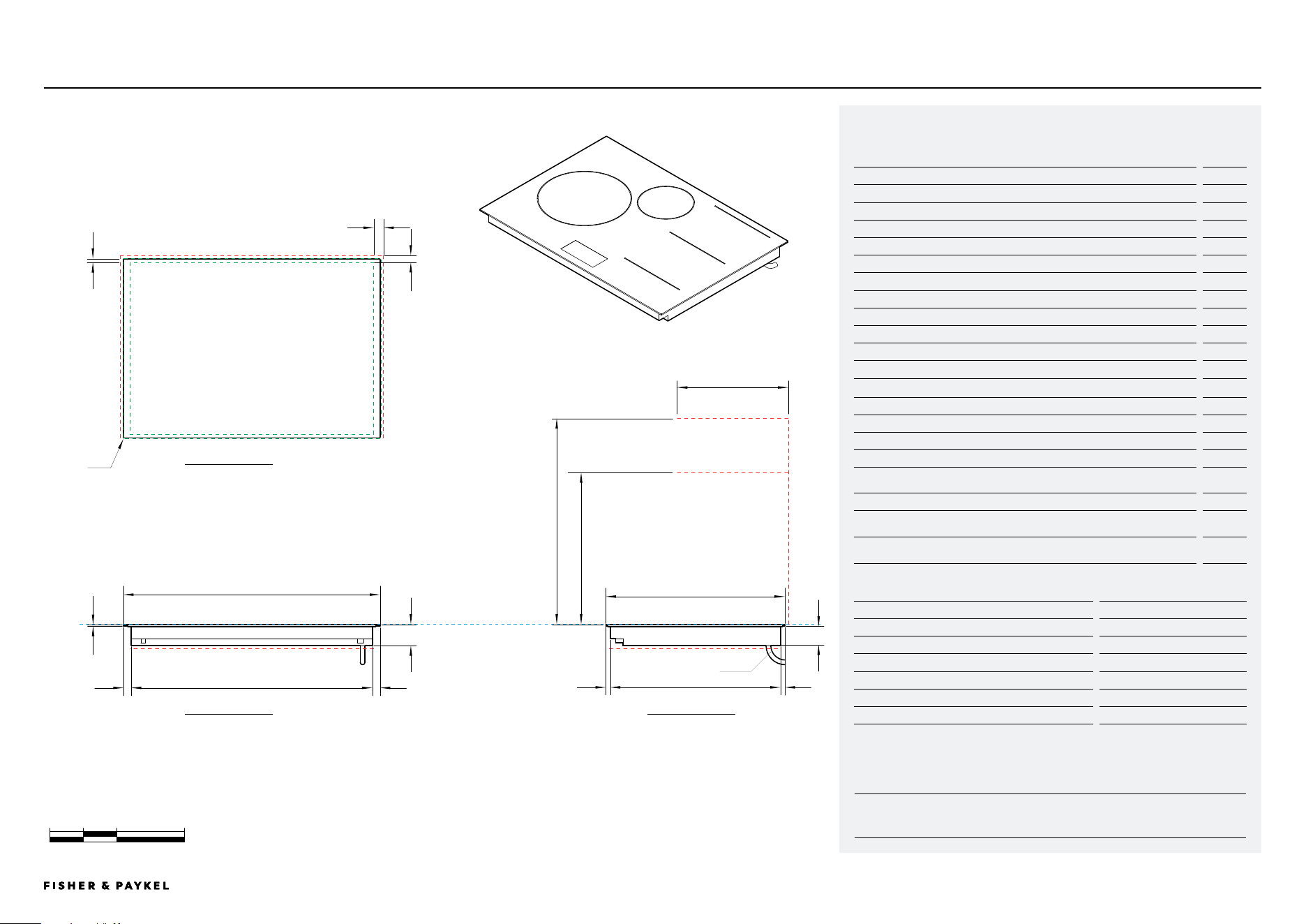
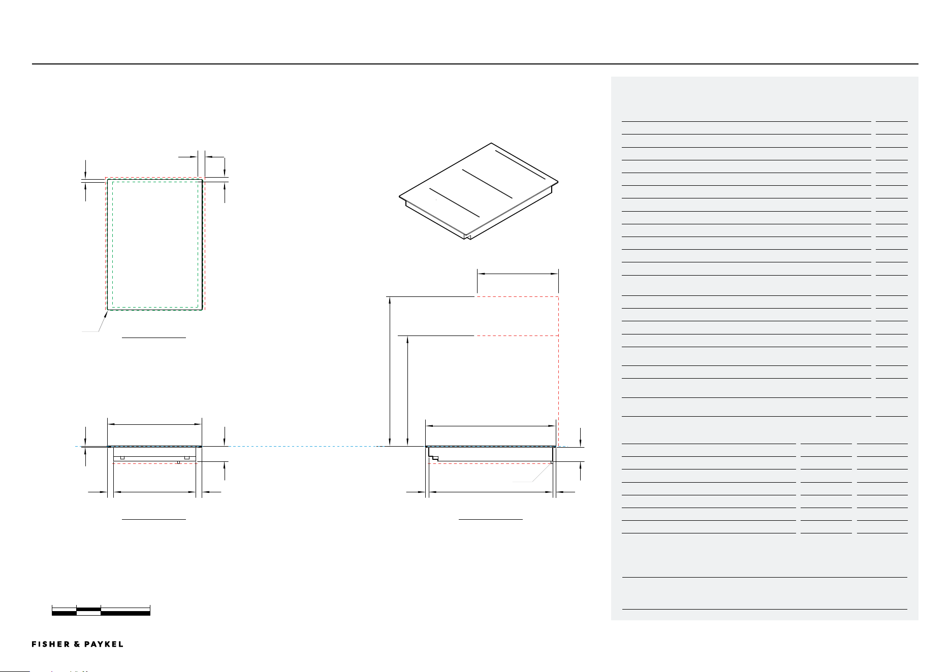
CI302DB1, CI302DG1
0 100 200 400
millimetres
Model no:
30cm Auxiliary Induction Hob, 2 Zones with SmartZone, Black - CI302DB1
30cm Auxiliary Induction Hob, 2 Zones with SmartZone, Grey - CI302DG1
Product Dimensions
mm
A Overall height of Hob
62
B Overall width of Hob
300
C Overall depth of Hob
530
D Height of Hob glass (includes flange and tape)
6
E Corner radius of glass
2
F Height of chassis
56
G Width of chassis
254
H Depth of chassis
504
I Width from side edges of Hob to chassis
23
J Depth from front edge of Hob to chassis
13.5
K Depth from back edge of Hob to chassis
12.5
Product Clearances
mm
L Minimum clearance from side edges of cutout to nearest combustible surface
29
M Minimum clearance from rear edge of cutout to nearest combustible surface
21
N Minimum clearance from cook surface to cooker hood or overhead cabinet
610
O Minimum clearance from cook surface to overhead cabinet not
directly above Hob
450
P Maximum depth of overhead cabinetry
330
Minimum ventilation gap between bottom of benchtop and top of cabinetry
fronts (not shown)
4
Minimum clearance from cook surface to top of any appliances, companion
product or obstruction below Hob
72
NOTE: The oven installed below the Hob MUST have a cooling fan. It is important that the induction Hob receives
adequate air supply. For ventilation requirements please refer to the installation manual.
Cutout Dimensions*
Proud mm
Flush mm
Overall width of cutout
262
262
Overall depth of cutout
507
509
Overall width of recess
-
304
Overall depth of recess
-
534
Overall height of recess
-
6.5
Recess corner radius
-
4
*Note cutout position is centred to the Hob.
DATA SHEETS | MODULAR HOBS
K
L
e
m
d
i
a
i
g
n o
j
f
k
h
p
CLEARANCE: COOKER HOOD,
OVERHEAD CABINET
CLEARANCE: OVERHEAD
CABINET NOT DIRECTLY ABOVE
CLEARANCE: BELOW HOBCLEARANCE: BELOW
HOB
DATUM: TOP OF COOKSURFACE
CLEARANCE: COMBUSTIBLE SURFACE
CLEARANCE: COMBUSTIBLE
SURFACE
b
385
c
530
POWER OUTLET
PRoFILE VIEW
FRoNT VIEW
PLAN VIEW
<< CONTENTS
© FISHER & PAYKEL LIMITED 2026 PAGE 1590003269D EU UK IE PLANNING GUIDE MoDULAR HobS VERSIoN D - MARCH 2026 PAGE 1590003269D EU UK IE PLANNING GUIDE MoDULAR HobS VERSIoN D - MARCH 2026
IMPORTANT NOTE: Throughout this guide, dimensions may vary by ±2mm (1/16''). Please
read the installation manual for detailed information on installing the product. For full
installation instructions & specifications visit fisherpaykel.com
INDICATES CABINETRY / PRODUCT DATUM ---------------------------------
INDICATES CABINETRY CLEARANCES ----------------------------------------
INDICATES CUTOUT ---------------------------------------------------------------
CIT302DX1
0 100 200 400
millimetres
Model no:
30cm Auxiliary Teppanyaki Hob, 2 Zones - CIT302DX1
Product Dimensions
mm
A Overall height of Hob
74
B Overall width of Hob
300
C Overall depth of Hob
530
D Height of stainless steel cook plate (includes flange and tape)
6
E Corner radius of Hob surface
2
F Height of chassis
68
G Width of chassis
251
H Depth of chassis
504
I Width from side edges of Hob to chassis
24.5
J Depth from front edge of Hob to chassis
13.5
K Depth from back edge of Hob to chassis
12.5
Product Clearances
mm
L Minimum clearance from side edges of cutout to nearest combustible surface
29
M Minimum clearance from rear edge of cutout to nearest combustible surface
21
N Minimum clearance from cook surface to cooker hood or overhead cabinet
610
O Minimum clearance from cook surface to overhead cabinet not
directly above Hob
450
P Maximum depth of overhead cabinetry
330
Minimum ventilation gap between bottom of benchtop and top of cabinetry
fronts (not shown)
4
Minimum clearance from cook surface to top of any appliances, companion
product or obstruction below Hob
86
NOTE: The oven installed below the Hob MUST have a cooling fan. It is important that the induction Hob receives
adequate air supply. For ventilation requirements please refer to the installation manual.
Cutout Dimensions*
Proud mm
Flush mm
Overall width of cutout
262
262
Overall depth of cutout
507
509
Overall width of recess
-
304
Overall depth of recess
-
534
Overall height of recess
-
6.5
Recess corner radius
-
4
*Note cutout position is centred to the Hob.
DATA SHEETS | MODULAR HOBS
K
L
e
m
d
i
a
i
g
n o
j
f
k
h
p
CLEARANCE: COOKER HOOD,
OVERHEAD CABINET
CLEARANCE: OVERHEAD
CABINET NOT DIRECTLY ABOVE
CLEARANCE: BELOW HOB
CLEARANCE: BELOW
HOB
DATUM: TOP OF COOKSURFACE
CLEARANCE: COMBUSTIBLE SURFACE
CLEARANCE: COMBUSTIBLE
SURFACE
b
385
c
530
POWER OUTLET
PRoFILE VIEW
FRoNT VIEW
PLAN VIEW
<< CONTENTS
© FISHER & PAYKEL LIMITED 2026 PAGE 1690003269D EU UK IE PLANNING GUIDE MoDULAR HobS VERSIoN D - MARCH 2026 PAGE 1690003269D EU UK IE PLANNING GUIDE MoDULAR HobS VERSIoN D - MARCH 2026
IMPORTANT NOTE: Throughout this guide, dimensions may vary by ±2mm (1/16''). Please
read the installation manual for detailed information on installing the product. For full
installation instructions & specifications visit fisherpaykel.com
INDICATES CABINETRY / PRODUCT DATUM ---------------------------------
INDICATES CABINETRY CLEARANCES ----------------------------------------
INDICATES CUTOUT ---------------------------------------------------------------
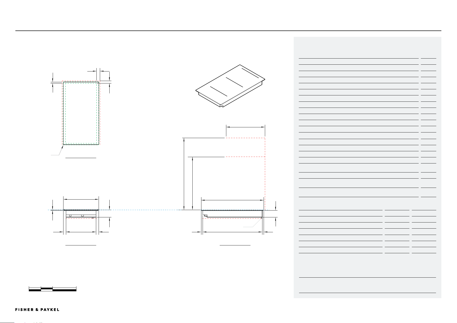
CI392DB1, CI392DG1
0 100 200 400
millimetres
Model no:
39cm Auxiliary Induction Hob, 2 Zones with SmartZone, Black - CI392DB1
39cm Auxiliary Induction Hob, 2 Zones with SmartZone, Grey - CI392DG1
Product Dimensions
mm
A Overall height of Hob
62
B Overall width of Hob
385
C Overall depth of Hob
530
D Height of Hob glass (includes flange and tape)
6
E Corner radius of glass
2
F Height of chassis
56
G Width of chassis
334
H Depth of chassis
504
I Width from side edges of Hob to chassis
25.5
J Depth from front edge of Hob to chassis
13.5
K Depth from back edge of Hob to chassis
12.5
Product Clearances
mm
L Minimum clearance from side edges of cutout to nearest combustible surface
29
M Minimum clearance from rear edge of cutout to nearest combustible surface
21
N Minimum clearance from cook surface to cooker hood or overhead cabinet
610
O Minimum clearance from cook surface to overhead cabinet not
directly above Hob
450
P Maximum depth of overhead cabinetry
330
Minimum ventilation gap between bottom of benchtop and top of cabinetry
fronts (not shown)
4
Minimum clearance from cook surface to top of any appliances, companion
product or obstruction below Hob
72
NOTE: The oven installed below the Hob MUST have a cooling fan. It is important that the induction Hob receives
adequate air supply. For ventilation requirements please refer to the installation manual.
Cutout Dimensions*
Proud mm
Flush mm
Overall width of cutout
347
347
Overall depth of cutout
507
509
Overall width of recess
-
389
Overall depth of recess
-
534
Overall height of recess
-
6.5
Recess corner radius
-
4
*Note cutout position is centred to the Hob.
DATA SHEETS | MODULAR HOBS
K
L
e
m
d
i
a
ig
n o
j
f
k
h
p
CLEARANCE: COOKER HOOD,
OVERHEAD CABINET
CLEARANCE: OVERHEAD
CABINET NOT DIRECTLY ABOVE
CLEARANCE: BELOW HOBCLEARANCE: BELOW HOB
DATUM: TOP OF COOKSURFACE
CLEARANCE: COMBUSTIBLE SURFACE
CLEARANCE: COMBUSTIBLE SURFACE
b
385
c
530
POWER OUTLET
PRoFILE VIEW
FRoNT VIEW
PLAN VIEW
<< CONTENTS
© FISHER & PAYKEL LIMITED 2026 PAGE 1790003269D EU UK IE PLANNING GUIDE MoDULAR HobS VERSIoN D - MARCH 2026 PAGE 1790003269D EU UK IE PLANNING GUIDE MoDULAR HobS VERSIoN D - MARCH 2026
IMPORTANT NOTE: Throughout this guide, dimensions may vary by ±2mm (1/16''). Please
read the installation manual for detailed information on installing the product. For full
installation instructions & specifications visit fisherpaykel.com
INDICATES CABINETRY / PRODUCT DATUM ---------------------------------
INDICATES CABINETRY CLEARANCES ----------------------------------------
INDICATES CUTOUT ---------------------------------------------------------------
CIT392DBX1
Model no:
39cm Auxiliary Teppanyaki Hob, 2 Zones - CIT392DBX1
Product Dimensions
mm
A Overall height of Hob
74
B Overall width of Hob
385
C Overall depth of Hob
530
D Height of stainless steel cook plate (includes flange and tape)
6
E Radius of the corner
2
F Height of chassis
68
G Width of chassis
336
H Depth of chassis
504
I Width from side edges of Hob to chassis
24.5
J Depth from front edge of Hob to chassis
13.5
K Depth from back edge of Hob to chassis
12.5
Product Clearances
mm
L Minimum clearance from side edges of cutout to nearest combustible surface
29
M Minimum clearance from rear edge of cutout to nearest combustible surface
21
N Minimum clearance from cook surface to cooker hood or overhead cabinet
610
O Minimum clearance from cook surface to overhead cabinet not
directly above Hob
450
P Maximum depth of overhead cabinetry
330
Minimum ventilation gap between bottom of benchtop and top of cabinetry
fronts (not shown)
4
Minimum clearance from cook surface to top of any appliances, companion
product or obstruction below Hob
86
NOTE: The oven installed below the Hob MUST have a cooling fan. It is important that the teppanyaki Hob
receives adequate air supply. For ventilation requirements please refer to page
Cutout Dimensions*
Proud mm
Flush mm
Overall width of cutout
347
347
Overall depth of cutout
507
509
Overall width of recess
-
389
Overall depth of recess
-
534
Overall height of recess
-
6.5
Recess corner radius
-
4
*Note cutout position is centred to the Hob.
0 100 200 400
millimetres
DATA SHEETS | MODULAR HOBS
K
L
e
m
d
i
a
ig
n o
j
f
k
h
p
CLEARANCE: COOKER HOOD,
OVERHEAD CABINET
CLEARANCE: OVERHEAD
CABINET NOT DIRECTLY ABOVE
CLEARANCE: BELOW HOBCLEARANCE: BELOW HOB
DATUM: TOP OF COOKSURFACE
CLEARANCE: COMBUSTIBLE SURFACE
CLEARANCE: COMBUSTIBLE SURFACE
b
385
c
530
POWER OUTLET
PRoFILE VIEW
FRoNT VIEW
PLAN VIEW
<< CONTENTS
© FISHER & PAYKEL APPLIANCES LIMITED 2026 PAGE 1890003269D EU UK IE PLANNING GUIDE MoDULAR HobS VERSIoN D - MARCH 2026
The Modular Auxiliary Downdraft models shown in this Planning Guide may not be available and are subject to
change at any time. For product availability, design planning and installation support please contact the Fisher
& Paykel design support team. designsupport@fisherpaykel.com
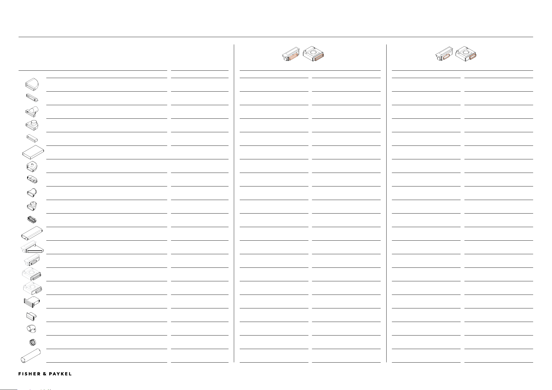
CD13DB
1 CD13DG1
13CM MODULAR AUXILIARY DOWNDRAFT, 300x
70 DUCTING
CD13DB
2 CD13DG2
13CM MODULAR AUXILIARY DOWNDRAFT, 222x
89 DUCTING
Ducting Component
Optional Accessory Part No.
Supplied
Optional accessory
Supplied
Optional accessory
Horizontal Elbow 90°, 300x70
E90H30X7
x1
Yes.
-
Yes. Adapter required.
Vertical Elbow 90°, 300x70
E90V30X7
x2
Yes.
-
Yes. Adapter required.
Straight Adaptor, 300x70 Rectangular to 150 Round
DA30X7D15
x1
Yes.
-
Yes. Adapter required.
Adaptor 90°, 300x70 Rectangular to 150 Round
DA90D30X7D15
x1
Yes.
-
Yes. Adapter required.
Connector, 300x70
C30X7
x1
Yes.
-
Yes. Adapter required.
Duct 1m, 300x70
D100X30X7
x1
Yes.
-
Yes. Adapter required.
Duct 90° Bend Horizontal, 222x89
E90H222X89
-
Yes. Adapter required.
x1
Yes.
Duct 90° Bend Vertical, 222x89
E90V222X89
-
Yes. Adapter required.
x2
Yes.
Duct Adaptor Straight, 222x89 to 150 Round
DA222X89D150
-
Yes. Adapter required.
x1
Yes.
Duct Adaptor 90°, 222x89 to 150 Round
DA90D222X89D150
-
Yes. Adapter required.
x1
Yes.
Duct Joiner Flexi, 222x89
C222X89
-
Yes. Adapter required.
x5
Yes.
Duct Straight Length 1m, 222x89
D1000X222X89
-
Yes. Adapter required.
x1
Yes.
Horizontal Elbow 90°, 300x70, Steel
E90H30X7S
-
Yes. For use under pyrolytic oven.
-
Not required for 222x89 ducting.
Mainbox Outlet Adaptor, 222x89
OAD222X89
-
Yes. Required for 222x89 ducting.
Supplied on mainbox.
Blower Outlet Adaptor, 300x70
OAB300X70
Supplied on blowerbox.
-
-
Yes. Required for 300 x 70 ducitng.
Blower Outlet Adaptor, 222x89
OAB222X89
-
Yes. Required for Recirculation kit
and/or 222x89 ducting.
Supplied on blowerbox.
-
Recirculation Kit
KRCID834
-
Yes. Blowerbox Outlet Adapter
222x89 is required.
-
Yes.
Outlet Grille, 222x89mm
DO-G-SS
-
Yes. Adapter required.
-
Yes.
Duct 90° Vertical, Round 150
E90V150
-
Yes.
-
Yes.
Duct Joiner Flexi, Round 150
C150
-
Yes.
-
Yes.
Duct Straight Length 1m, Round 150
D1000X150
-
Yes.
-
Yes.
MODULAR AUXILIARY DOWNDRAFT COMPONENT OVERVIEW SPECIFICATION GUIDE | MODULAR HOBS
<< CONTENTS
© FISHER & PAYKEL LIMITED 2026 PAGE 1990003269D EU UK IE PLANNING GUIDE MoDULAR HobS VERSIoN D - MARCH 2026 PAGE 1990003269D EU UK IE PLANNING GUIDE MoDULAR HobS VERSIoN D - MARCH 2026
INDICATES CABINETRY / PRODUCT DATUM ---------------------------------
INDICATES CABINETRY CLEARANCES ----------------------------------------
INDICATES CUTOUT ---------------------------------------------------------------
IMPORTANT NOTE: Throughout this guide, dimensions may vary by ±2mm (1/16''). Please
read the installation manual for detailed information on installing the product. For full
installation instructions & specifications visit fisherpaykel.com
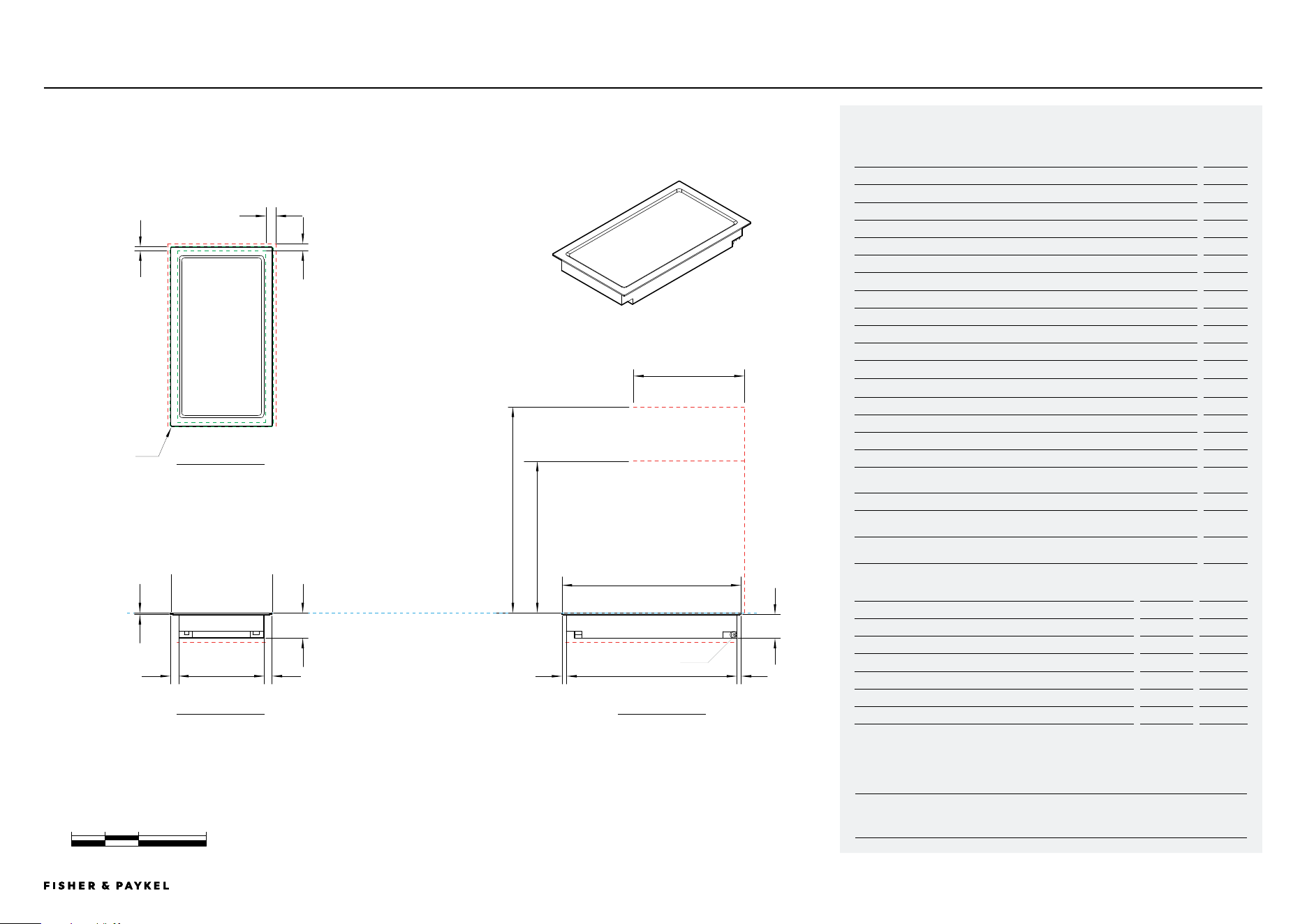
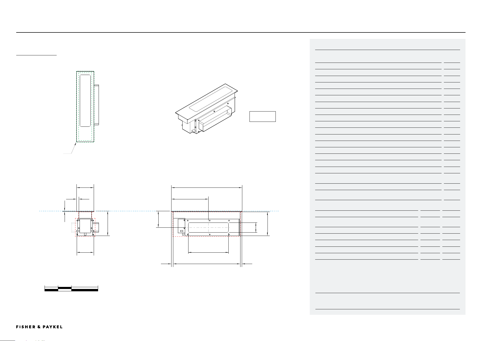
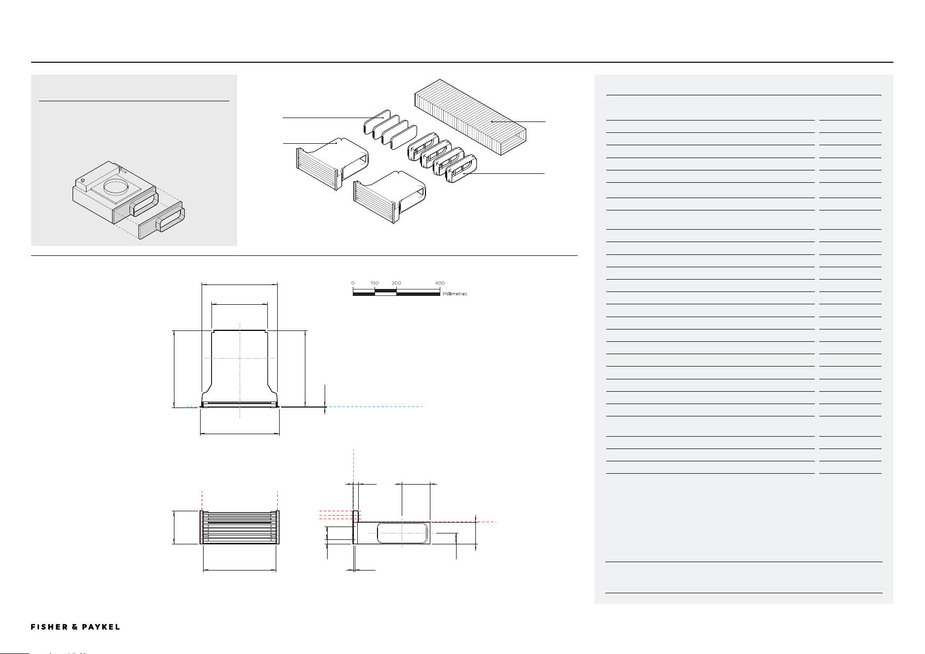
CD13DB1 | CD13DG1 | MAINBOX
0 100 200 400
millimetres
DATUM:
TOP OF COOK SURFACE
Model no:
13cm Modular Auxiliary Downdraft Rangehood, Black - CD13DB1
13cm Modular Auxiliary Downdraft Rangehood, Grey - CD13DG1
Product Dimensions
mm
A Overall height of mainbox
186
B Overall width of mainbox
130
C Overall depth of mainbox
530
D Height of glass (includes flange and tape)
6
E Corner radius of glass
2
F Height of chassis
180
G Width of lower chassis (includes communication ports)
126
H Depth of chassis
504
I Width from sides of glass to neck of chassis
18
J Depth from front edge of glass to chassis
14
K Depth from back edge of glass to chassis
13
L Height from top of glass to centre of outlet
124
M Depth from front edge of glass to centre of outlet
279
N Width from edge of glass to outside of outlet
36
O Height of ducting
70
P Width of ducting
300
Product Clearances
mm
Minimum clearance from top surface to top of any appliances, companion
product or obstruction below mainbox
200
Cutout Dimensions*
Proud mm
Flush mm
Overall width of cutout
98
98
Overall depth of cutout
507
509
Overall width of recess
-
134
Overall depth of recess
-
534
Overall height of recess
-
6.5
Recess corner radius
-
4
* Note cutout position is centred to the Hob.
MAINBOX
300X70
DATA SHEETS | MODULAR HOBS
a
b
g
i
d
c
kh
j
f
e
m
l
PROFILE VIEW
FRONT VIEW
PLAN VIEW
o
p
<< CONTENTS
© FISHER & PAYKEL LIMITED 2026 PAGE 2090003269D EU UK IE PLANNING GUIDE MoDULAR HobS VERSIoN D - MARCH 2026 PAGE 2090003269D EU UK IE PLANNING GUIDE MoDULAR HobS VERSIoN D - MARCH 2026
INDICATES CABINETRY / PRODUCT DATUM ---------------------------------
INDICATES CABINETRY CLEARANCES ----------------------------------------
INDICATES CUTOUT ---------------------------------------------------------------
IMPORTANT NOTE: Throughout this guide, dimensions may vary by ±2mm (1/16''). Please
read the installation manual for detailed information on installing the product. For full
installation instructions & specifications visit fisherpaykel.com
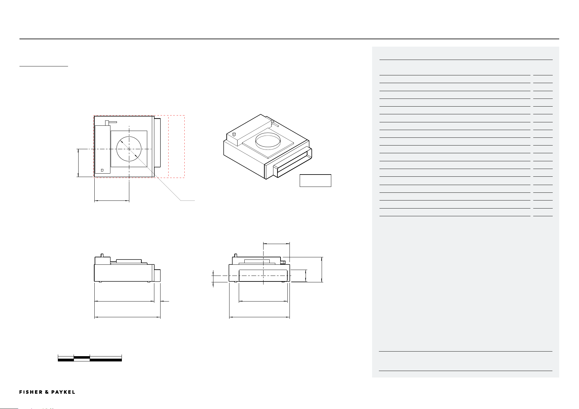
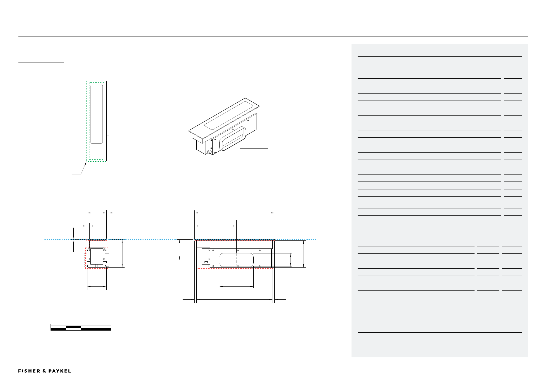
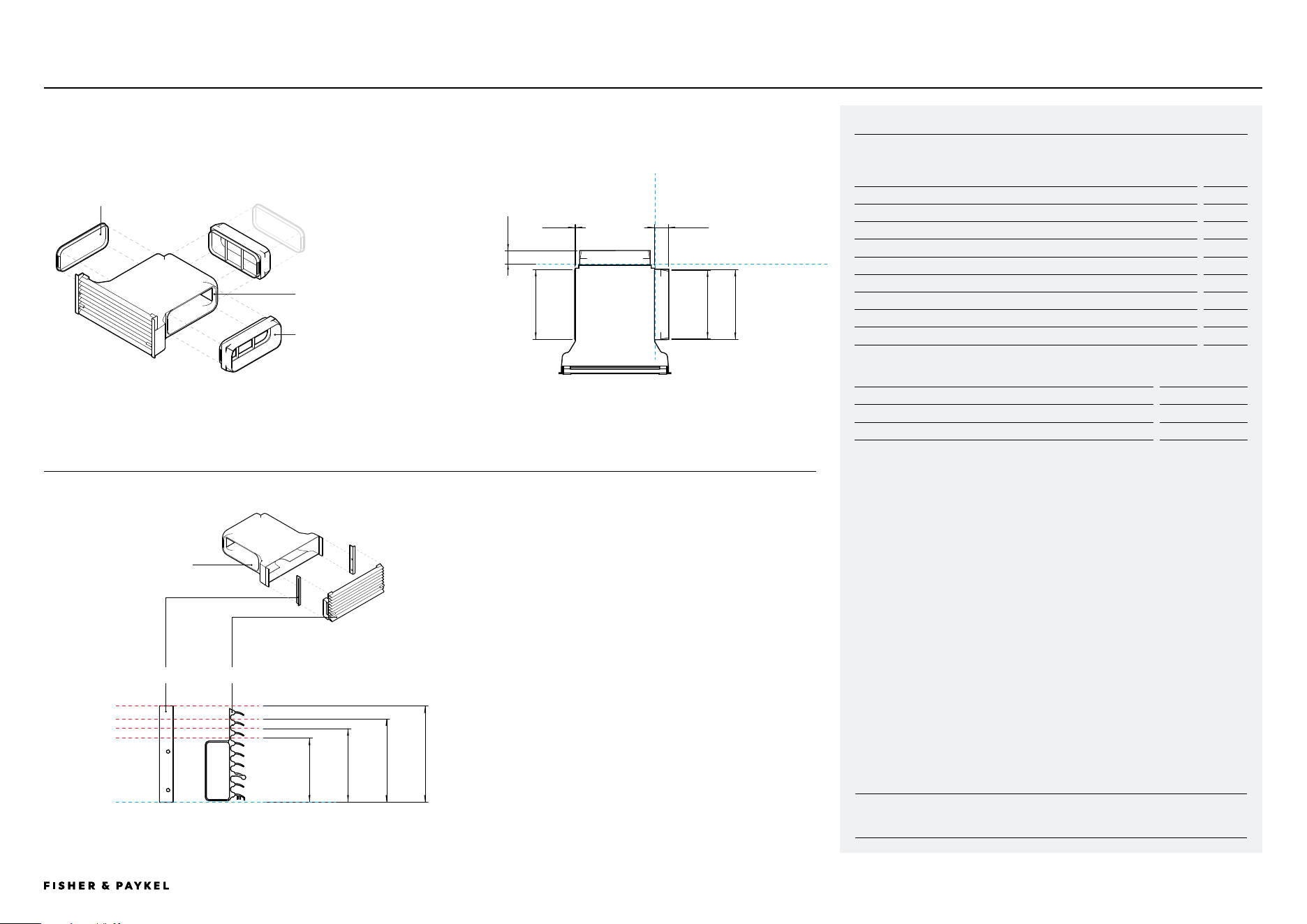
CD13DB1 | CD13DG1 | BLOWERBOX
0 100 200 400
millimetres
Model no:
13cm Modular Auxiliary Downdraft Rangehood, Black - CD13DB1
13cm Modular Auxiliary Downdraft Rangehood, Grey - CD13DG1
Product Dimensions
mm
A Overall height of blowerbox
156
B Overall width of blowerbox (including outlet)
413
C Overall depth of blowerbox
379
D Width of blowerbox
375
E Width from corner to centre of inlet
217
F Depth from corner to centre of inlet
175
G Internal diameter of inlet
154
H Height from base of product to centre of outlet
41
I Width from outside of chassis to centre of outlet
166
J Height of outlet
70
K Width of outlet
300
L Depth of outlet
38
Cutout Dimensions*
mm
Recommended width of cutout **
570
Minimum width of cutout ***
470
Depth of cutout
390
* Blowerbox can be rotated to achieve desired outlet direction, cutout dimensions must be rotated accordingly.
** Recommended width allows greater access to outlet during installation.
*** Clearance only for blowerbox, does not provide allowances for connecting to ducting.
BLOWERBOX
DATA SHEETS | MODULAR HOBS
A
B
C
D
F
E
G
H
K
J
L
I
PROFILE VIEW
FRONT VIEW
PLAN VIEW
300X70
<< CONTENTS
© FISHER & PAYKEL LIMITED 2026 PAGE 2190003269D EU UK IE PLANNING GUIDE MoDULAR HobS VERSIoN D - MARCH 2026 PAGE 2190003269D EU UK IE PLANNING GUIDE MoDULAR HobS VERSIoN D - MARCH 2026
INDICATES CABINETRY / PRODUCT DATUM ---------------------------------
INDICATES CABINETRY CLEARANCES ----------------------------------------
INDICATES CUTOUT ---------------------------------------------------------------
IMPORTANT NOTE: Throughout this guide, dimensions may vary by ±2mm (1/16''). Please
read the installation manual for detailed information on installing the product. For full
installation instructions & specifications visit fisherpaykel.com
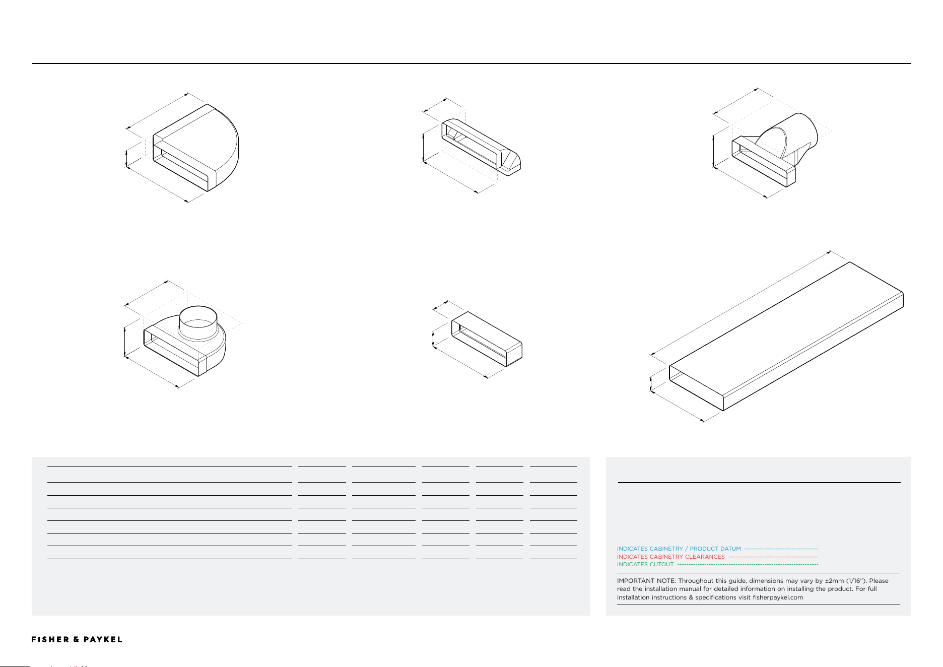
CD13DB1 | CD13DG1 | SUPPLIED 300X70 DUCTING
Part
Supplied
Accessory No.
A
Height
B
Width
C
Depth
1 Horizontal Elbow, 90°, 300x70mm*
x1
E90H30X7
77
352
352
2 Vertical Elbow, 90°, 300x70mm*
x2
E90V30X7
137
307
137
3 Straight Adaptor, 300x70mm Rectangular to 150mm Round*
x1
DA30X7D15
150
307
250
4 Duct Adaptor, 90°, 300x70mm Rectangular to 150mm Round*
x1
DA90D30X7D15
139
307
240
5 Connector for 300x70mm Ducting*
x1
C30X7
77
307
85
6 Duct, 1m, 300x70mm*
x1
D100X30X7
73
303
1000
* Component also available as an optional accessory
** Must be used over a pyrolytic oven
*** For connection to Recirculation Kit KRCID834
a
b
c
a
b
c
a
b
c
a
b
c
a
b
c
a
b
c
DATA SHEETS | MODULAR HOBS
CRITICAL NOTE
It is essential to work with CAD downloads of Modular Downdraft components to
design a ducting layout best suited to specific cabinetry requirements.
For design planning and installation support please contact the Fisher & Paykel design
support team. designsupport@fisherpaykel.com
1 Horizontal Elbow 90°, 300x70 2 Vertical Elbow 90°, 300x70 3 Straight Adapter, 300x70 Rectangular to 150 Round
4 Duct Adapter 90°, 300x70 Rectangular to 150 Round 5 Connector, 300x70 6 Duct 1M, 300x70
<< CONTENTS
© FISHER & PAYKEL LIMITED 2026 PAGE 2290003269D EU UK IE PLANNING GUIDE MoDULAR HobS VERSIoN D - MARCH 2026 PAGE 2290003269D EU UK IE PLANNING GUIDE MoDULAR HobS VERSIoN D - MARCH 2026
INDICATES CABINETRY / PRODUCT DATUM ---------------------------------
INDICATES CABINETRY CLEARANCES ----------------------------------------
INDICATES CUTOUT ---------------------------------------------------------------
IMPORTANT NOTE: Throughout this guide, dimensions may vary by ±2mm (1/16''). Please
read the installation manual for detailed information on installing the product. For full
installation instructions & specifications visit fisherpaykel.com
CD13DB2 | CD13DG2 | MAINBOX
Model no:
13cm Modular Auxiliary Downdraft Rangehood, Black - CD13DB2
13cm Modular Auxiliary Downdraft Rangehood, Grey - CD13DG2
Product Dimensions
mm
A Overall height of mainbox
186
B Overall width of mainbox
130
C Overall depth of mainbox
530
D Height of glass (includes flange and tape)
6
E Corner radius of glass
2
F Height of chassis
180
G Width of lower chassis (includes communication ports)
126
H Depth of chassis
504
I Width from sides of glass to neck of chassis
18
J Depth from front edge of glass to chassis
14
K Depth from back edge of glass to chassis
13
L Height from top of glass to centre of outlet
136
M Depth from front edge of glass to centre of outlet
279
N Width from edge of glass to outside of outlet
36
O Height of ducting
89
P Width of ducting
222
Product Clearances
mm
Minimum clearance from top surface to top of any appliances, companion
product or obstruction below mainbox
200
Cutout Dimensions*
Proud mm
Flush mm
Overall width of cutout
98
98
Overall depth of cutout
507
509
Overall width of recess
-
134
Overall depth of recess
-
534
Overall height of recess
-
6.5
Recess corner radius
-
4
* Note cutout position is centred to the Hob.
MAINBOX
0 100 200 400
millimetres
DATUM:
TOP OF COOK SURFACE
DATA SHEETS | MODULAR HOBS
222X89
a
b
g
i
d
c
kh
j
f
e
m
l
PROFILE VIEW
FRONT VIEW
PLAN VIEW
o
p
<< CONTENTS
© FISHER & PAYKEL LIMITED 2026 PAGE 2390003269D EU UK IE PLANNING GUIDE MoDULAR HobS VERSIoN D - MARCH 2026 PAGE 2390003269D EU UK IE PLANNING GUIDE MoDULAR HobS VERSIoN D - MARCH 2026
INDICATES CABINETRY / PRODUCT DATUM ---------------------------------
INDICATES CABINETRY CLEARANCES ----------------------------------------
INDICATES CUTOUT ---------------------------------------------------------------
IMPORTANT NOTE: Throughout this guide, dimensions may vary by ±2mm (1/16''). Please
read the installation manual for detailed information on installing the product. For full
installation instructions & specifications visit fisherpaykel.com
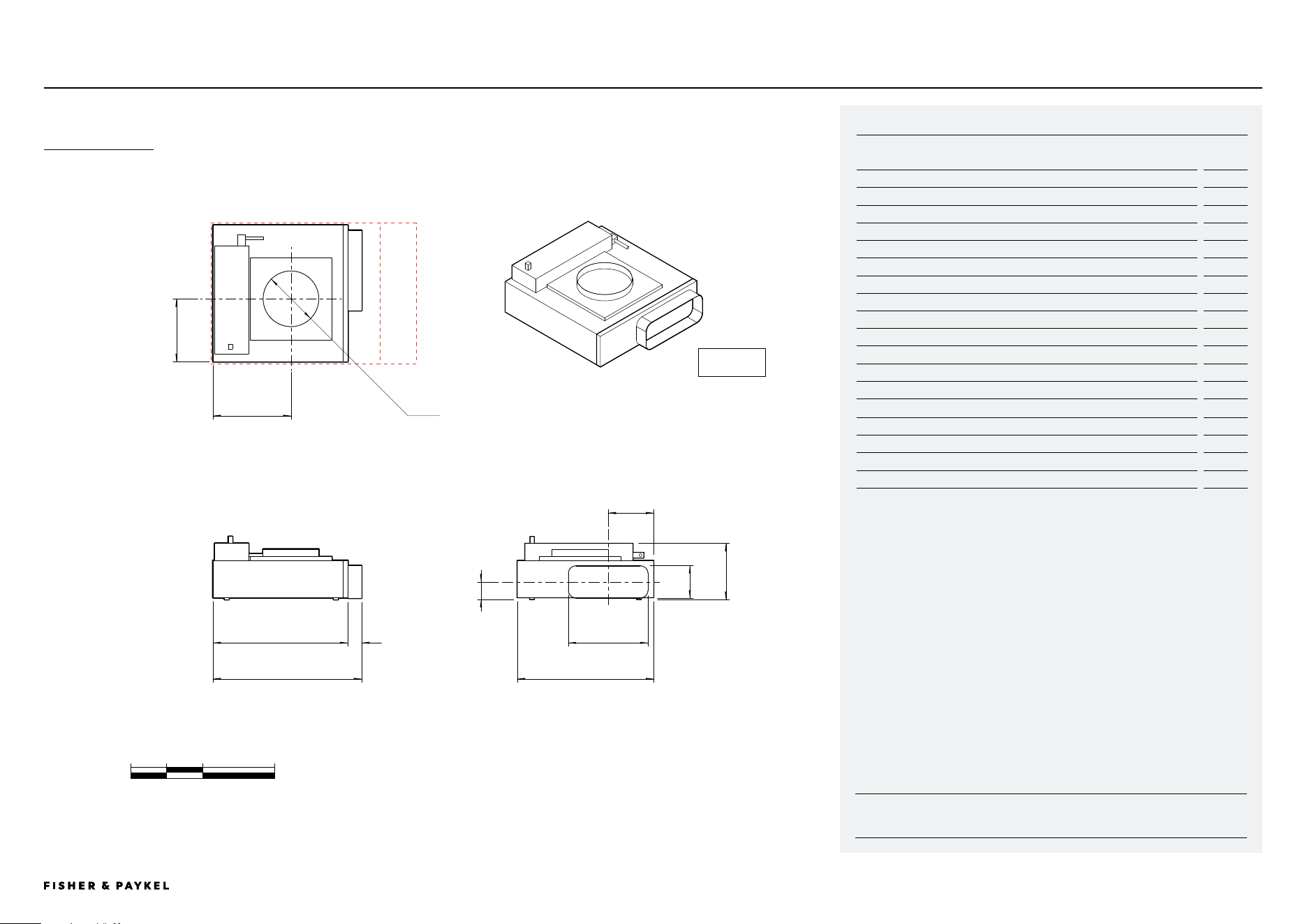
CD13DB2 | CD13DG2 | BLOWERBOX
0 100 200 400
millimetres
Model no:
13cm Modular Auxiliary Downdraft Rangehood, Black - CD13DB2
13cm Modular Auxiliary Downdraft Rangehood, Grey - CD13DG2
Product Dimensions
mm
A Overall height of blowerbox
156
B Overall width of blowerbox (including outlet)
413
C Overall depth of blowerbox
379
D Width of blowerbox chassis
375
E Width from corner to centre of inlet
217
F Depth from corner to centre of inlet
175
G Internal diameter of inlet
154
H Height from base of product to centre of outlet
49
I Width from outside of chassis to centre of outlet
127
J Height of outlet
89
K Width of outlet
222
L Depth of outlet
38
Cutout Dimensions*
mm
Recommended width of cutout **
570
Minimum width of cutout ***
470
Depth of cutout
390
* Blowerbox can be rotated to achieve desired outlet direction, cutout dimensions must be rotated accordingly.
** Recommended width allows greater access to outlet during installation.
*** Clearance only for blowerbox, does not provide allowances for connecting to ducting.
BLOWERBOX
A
B C
D
F
E
G
H
K
J
L
I
222X89
DATA SHEETS | MODULAR HOBS
PROFILE VIEW
FRONT VIEW
PLAN VIEW
<< CONTENTS
© FISHER & PAYKEL LIMITED 2026 PAGE 2490003269D EU UK IE PLANNING GUIDE MoDULAR HobS VERSIoN D - MARCH 2026 PAGE 2490003269D EU UK IE PLANNING GUIDE MoDULAR HobS VERSIoN D - MARCH 2026
INDICATES CABINETRY / PRODUCT DATUM ---------------------------------
INDICATES CABINETRY CLEARANCES ----------------------------------------
INDICATES CUTOUT ---------------------------------------------------------------
IMPORTANT NOTE: Throughout this guide, dimensions may vary by ±2mm (1/16''). Please
read the installation manual for detailed information on installing the product. For full
installation instructions & specifications visit fisherpaykel.com
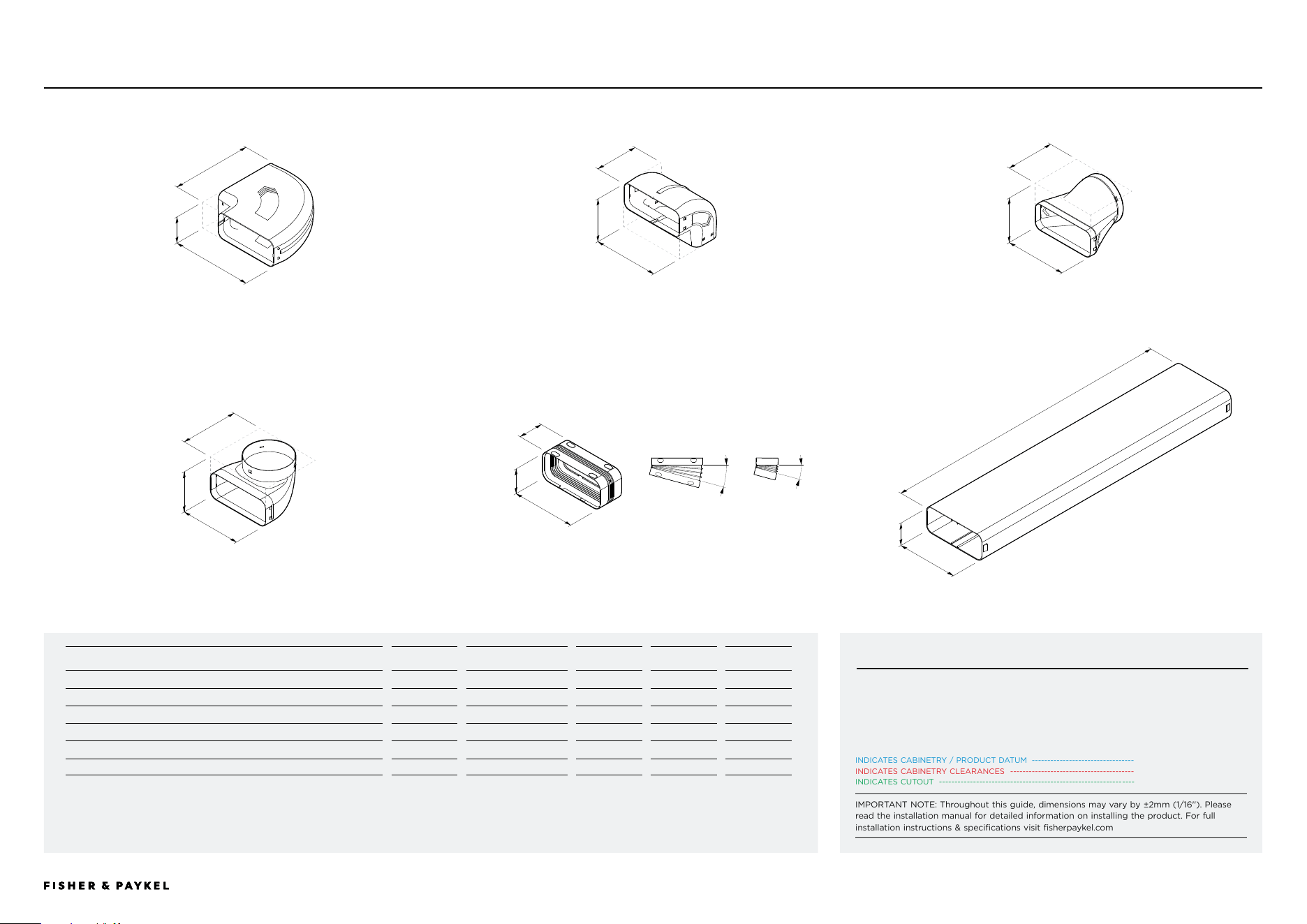
CD13DB2 | CD13BG2 | SUPPLIED 222 X 89 DUCTING
Part
Supplied
Part No
A
Height
B
Width
C
Depth
1 Duct 90° Bend Horizontal 222x89*
x1
E90H222X89
98
290
290
2 Duct 90° Bend Vertical 222x89*
x2
E90V222X89
164
228
164
3 Duct Adaptor Straight, 222x89 to 150*
x1
DA222X89D150
154
227
166
4 Duct Adaptor 90°, 222x89 to 150*
x1
DA90D222X89D150
137
227
200
5 Duct Joiner Flexi, 222x89*
x5
C222X89
100
233
85
6 Duct Straight Length 1m, 222x89*
x1
D1000X222X89
89
222
1000
* Component also available as an optional accessory
a
b
c
a
b
c
a
b
c
a
b
c
a
b
c
a
b
c
DATA SHEETS | MODULAR HOBS
1 90° Bend Horizontal, 222x89 2 90° Bend Vertical, 222x89 3 Adapter Straight, 222x89 to 150
4 Adapter 90°, 222x89 to 150 5 Joiner Flexi, 222x89 6 Duct Straight Length 1m, 222x89
15°
15°
CRITICAL NOTE
It is essential to work with CAD downloads of Modular Downdraft components to
design a ducting layout best suited to specific cabinetry requirements.
For design planning and installation support please contact the Fisher & Paykel design
support team. designsupport@fisherpaykel.com
<< CONTENTS
© FISHER & PAYKEL LIMITED 2026 PAGE 2590003269D EU UK IE PLANNING GUIDE MoDULAR HobS VERSIoN D - MARCH 2026 PAGE 2590003269D EU UK IE PLANNING GUIDE MoDULAR HobS VERSIoN D - MARCH 2026
INDICATES CABINETRY / PRODUCT DATUM ---------------------------------
INDICATES CABINETRY CLEARANCES ----------------------------------------
INDICATES CUTOUT ---------------------------------------------------------------
IMPORTANT NOTE: Throughout this guide, dimensions may vary by ±2mm (1/16''). Please
read the installation manual for detailed information on installing the product. For full
installation instructions & specifications visit fisherpaykel.com
IMPORTANT NOTE
If specifying Recirculation Kit KRCID834 with
CD13DB1 and CD13DG1, the Blowerbox Outlet
Adaptor 222x89 (OAB222X89) is required.
44.00
418.50
44.00
418.50
38.00
412.50412.50
38.00
3.90
3.90
82.60
304.80 16.40304.80 16.40
57.20
49.10
126.40
90.40
3.90
15.40222.00
166.00
40.50
73.00
4.00
14.50303.00
KRCID834
Optional Accessory Model no:
Recirculation Kit - KRCID834
Component Description
Quanitity
Filter Box Assembly
x2
Duct Adaptor
x4
Cap
x4
3m Flexible Ducting
x1
Product Dimensions
mm
A Overall height of filter box assembly (louvres can be trimmed to
suit kickstrip)
150/130/115/100
B Overall width of filter box assembly
362
C Overall depth of filter box assembly
354
D Height of filter box
98
E Width of filter box at front
346
F Width of filter box at rear
256
G Depth of filter box (excludes bracket)
351
H Depth of bracket flange
1
I Depth of bracket and louvres
26
J Height from bottom of filter box to centre of outlets
49
K Depth from rear of filter box to centre of side outlets
128
L Height from bottom of bracket to lower hole centre
19
M Height between hole centres
60
N Depth from rear of bracket flange to hole centre
7
O Hole diameter
4
P Width of louvres
332
Kickstrip Dimensions
mm
Height of kickstrip (louvres trimmed to suit)
150/130/115/100
Overall width of cutout
347
FRONT VIEW
PLAN VIEW
PROFILE VIEW
G
k
f
D
i
e
C
A
B
h
jl
m
p
n
DATUM : FRONT OF KICKSTRIP
DATUM : FRONT OF KICKSTRIP
CLEARANCE : KICKSTRIP CUTOUT
CLEARANCE : MINIMUM KICK HEIGHT
CLEARANCE :
OPTIONAL KICK HEIGHTS
EXPLODED ISOMETRIC VIEW
DUCT
ADAPTOR
FLEXIBLE
DUCTING
CAP
FILTERBOX
ASSEMBLY
DATA SHEETS | MODULAR HOBS
<< CONTENTS
© FISHER & PAYKEL LIMITED 2026 PAGE 2690003269D EU UK IE PLANNING GUIDE MoDULAR HobS VERSIoN D - MARCH 2026 PAGE 2690003269D EU UK IE PLANNING GUIDE MoDULAR HobS VERSIoN D - MARCH 2026
INDICATES CABINETRY / PRODUCT DATUM ---------------------------------
INDICATES CABINETRY CLEARANCES ----------------------------------------
INDICATES CUTOUT ---------------------------------------------------------------
IMPORTANT NOTE: Throughout this guide, dimensions may vary by ±2mm (1/16''). Please
read the installation manual for detailed information on installing the product. For full
installation instructions & specifications visit fisherpaykel.com
qu
sv t
CAP (X2)
FILTER BOX ASSEMBLY (X1)
DUCT ADAPTOR (X2)
Adaptor can be connected to
Flexible Ducting (supplied)
or
Straight Ducting 222 x 89
PLAN VIEW
EXPLODED ISOMETRIC VIEW
FILTER BOX ASSEMBLY WITH DUCT ADAPTOR AND CAPS - X2 SETS SUPPLIED
Position of caps and adaptors can be interchanged to suit ducting layout
r
DATUM : DUCT INTERFACE
DATUM : DUCT INTERFACE
Optional Accessory Model no:
Recirculation Kit - KRCID834
Product Dimensions
mm
A Distance from edge of duct adaptor to edge of filter box
46
B Internal depth of female end of duct adaptor
43
C Overall length of duct adaptor
227
D Internal length of female end of duct adaptor
223
E Overall height of duct adaptor (not shown)
94
F Internal height of female end of duct adaptor (not shown)
90
G Thickness of cap from edge of filter box
2
H Length of cap
226
I Height of cap (not shown)
93
Kickstrip Dimensions
mm
Height of kickstrip (louvres trimmed to suit)
150/130/115/100
Overall width of cutout
347
KRCID834
PROFILE VIEW
BRACKET LOUVRES
EXPLODED PROFILE VIEW
BRACKET + LOUVRES
DATUM : FLOOR
EXPLODED ISO VIEW
FILTER BOX, BRACKETS +
LOUVRES
FILTER BOX
DATUM : OPTIONAL
KICK HEIGHTS
h
100
j
115
l
130
n
150
DATA SHEETS | MODULAR HOBS
<< CONTENTS
© FISHER & PAYKEL LIMITED 2026 PAGE 2790003269D EU UK IE PLANNING GUIDE MoDULAR HobS VERSIoN D - MARCH 2026 PAGE 2790003269D EU UK IE PLANNING GUIDE MoDULAR HobS VERSIoN D - MARCH 2026
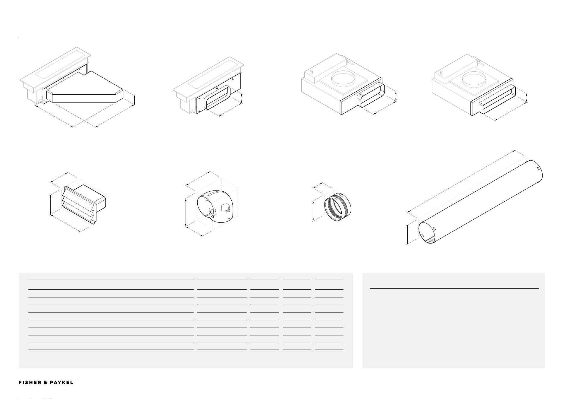
OPTIONAL ACCESSORIES
Optional Accessory
Part No
A
Height
B
Width
C
Depth
1 Horizontal Elbow 90°, 300x70mm, Steel*
E90H30X7S
74
350
363
2 Mainbox Outlet Adaptor, 222x89mm (outlet dimensions shown)
OAD222X89
89
222
-
3 Blower Outlet Adaptor, 222x89mm (outlet dimensions shown)
OAB222X89
89
222
-
4 Blower Outlet Adaptor, 300x70mm (outlet dimensions shown)
OAB300X70
70
300
-
5 Outlet Grille, 222x89
DO-G-SS
161
290
163
6 Duct 90° Vertical, Round 150
E90V150
227
157
227
7 Duct Joiner Flexi, Round 150
C150
163
-
85
8 Duct Straight Length 1m, Round 150
D1000X150
150
-
1000
* for installation directly above an oven when 300x70 ducting is used. Not required for 222x89 ducting.
DATA SHEETS | MODULAR HOBS
CRITICAL NOTE
It is essential to work with CAD downloads of Modular Downdraft components to
design a ducting layout best suited to specific cabinetry requirements.
For design planning and installation support please contact the Fisher & Paykel design
support team. designsupport@fisherpaykel.com
a
b
c
a
b
1
Horizontal Elbow, 90°, 300x70, Steel 3 Blowerbox Outlet Adapter, 222x892 Mainbox Outlet Adaptor, 222x89 4 Blowerbox Outlet Adapter, 300x70
a
b
a
b
a
c
a
b
c
a
c
6
90° Bend, Round 150 7 Joiner Flexi, Round 150 8 Duct Straight Length 1m, Round, 150
a
b
c
5
Outlet Grille, 222x89
<< CONTENTS

© FISHER & PAYKEL LIMITED 2026 PAGE 2890003269D EU UK IE PLANNING GUIDE MoDULAR HobS - VERSIoN D - MARCH 2026
PRODUCT DECISIONS
© FISHER & PAYKEL LIMITED 2026 PAGE 2990003269D EU UK IE PLANNING GUIDE MoDULAR HobS VERSIoN D - MARCH 2026
The models shown in this Planning Guide may not be available in all markets and are subject to change at any time. Product specifications may vary from those shown. This Planning Guide should not be used as installation guidance for any product. Further information is required to safely and correctly install the
products featured here. Specific installation guidance will be available with the product on delivery and on our website fisherpaykel.com
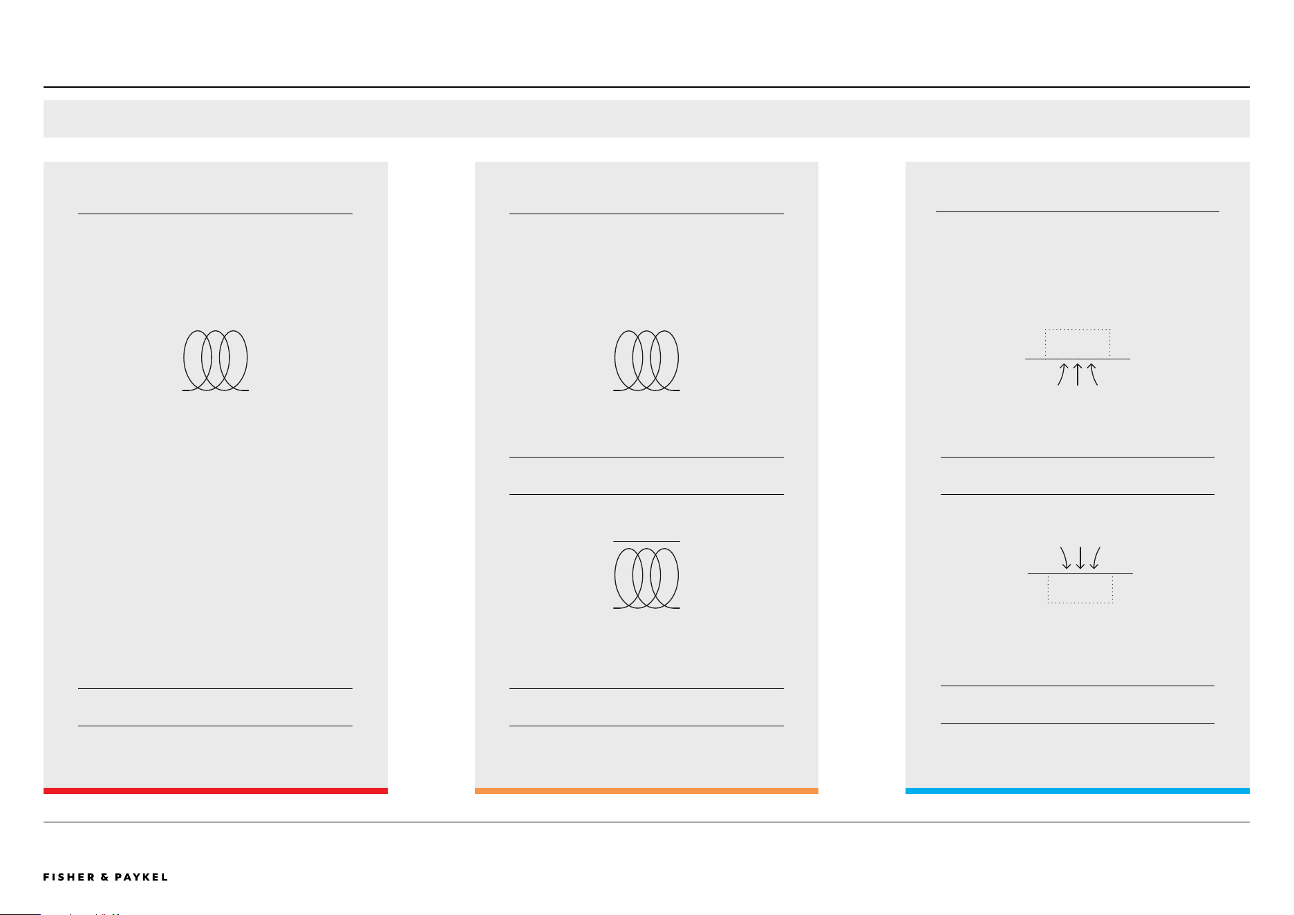
MODULAR SYSTEM CAPABILITIES
PRIMARY HOB
Touchscreen user interface.
Controls complete modular suite.
Available in 39cm, 60cm, 76cm and 90cm widths.
AUXILIARY HOB
No user interface.
Must be paired with a primary hob.
Controlled by the primary hob.
Available in 30cm and 39cm widths.
VENTILATION
The downdraft auxiliary ventilation module has
no user interface and must be paired with and
controlled by the primary hob.
Overhead can be controlled by the primary hob.
+
_
+
_
CONNECTED EXPERIENCE
INDUCTION INDUCTION
TEPPANYAKI AUXILIARY DOWNDRAFT VENTILATION
OVERHEAD VENTILATION
MIX AND MATCH EITHER OR
ESSENTIAL
1X MAXIMUM
RECOMMENDED
OVERHEAD 1X
DOWNDRAFT 1-2X
OPTIONAL
0-2X
PRODUCT DECISIONS | MODULAR HOBS
<< CONTENTS
© FISHER & PAYKEL LIMITED 2026 PAGE 3090003269D EU UK IE PLANNING GUIDE MoDULAR HobS VERSIoN D - MARCH 2026
The models shown in this Planning Guide may not be available in all markets and are subject to change at any time. Product specifications may vary from those shown. This Planning Guide should not be used as installation guidance for any product. Further information is required to safely and correctly install the
products featured here. Specific installation guidance will be available with the product on delivery and on our website fisherpaykel.com
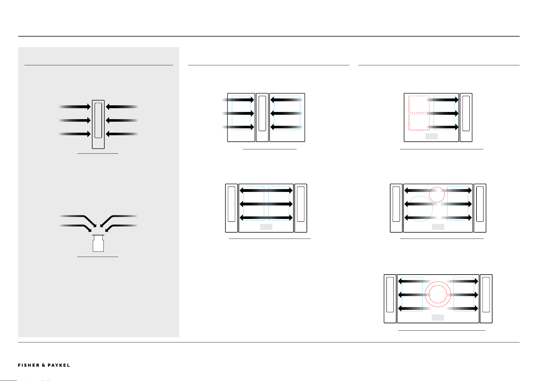
DOWNDRAFT VENTILATION
The modular ventilation unit is a downdraft ventilation system that
efficiently extracts air across and downwards.
The modular ventilation unit provides efficient ventilation to
adjacent cook zones. Consideration of cook zone layout and cook
module size is critical for optimum pairing of ventilation type and
quantity.
Important: Where modular ventilation is unable to provide efficient
venting it is recommended that overhead extraction is chosen.
WARNING: The Modular Ventilation unit cannot be used alongside
a gas Hob.
MODULAR VENTILATION CAPABILITIES
SUFFICIENT VENTILATION
ADJACENT COOKZONES ARE EFFECTIVELY VENTED
INSUFFICIENT VENTILATION
NON-ADJACENT COOKZONES ARE NOT SUFFICIENTLY VENTED
30CM + 39CM MoDULES
60CM PRIMARY MoDULE WITH 2X DoWNDRAFT
60CM PRIMARY MoDULE WITH 1X DoWNDRAFT
76CM PRIMARY MoDULE WITH 2X DoWNDRAFT
90CM PRIMARY MoDULE WITH 2X DoWNDRAFT
ToP VIEW
FRoNT VIEW
PRODUCT DECISIONS | MODULAR HOBS
<< CONTENTS
© FISHER & PAYKEL LIMITED 2026 PAGE 3190003269D EU UK IE PLANNING GUIDE MoDULAR HobS VERSIoN D - MARCH 2026
The models shown in this Planning Guide may not be available in all markets and are subject to change at any time. Product specifications may vary from those shown. This Planning Guide should not be used as installation guidance for any product. Further information is required to safely and correctly install the
products featured here. Specific installation guidance will be available with the product on delivery and on our website fisherpaykel.com
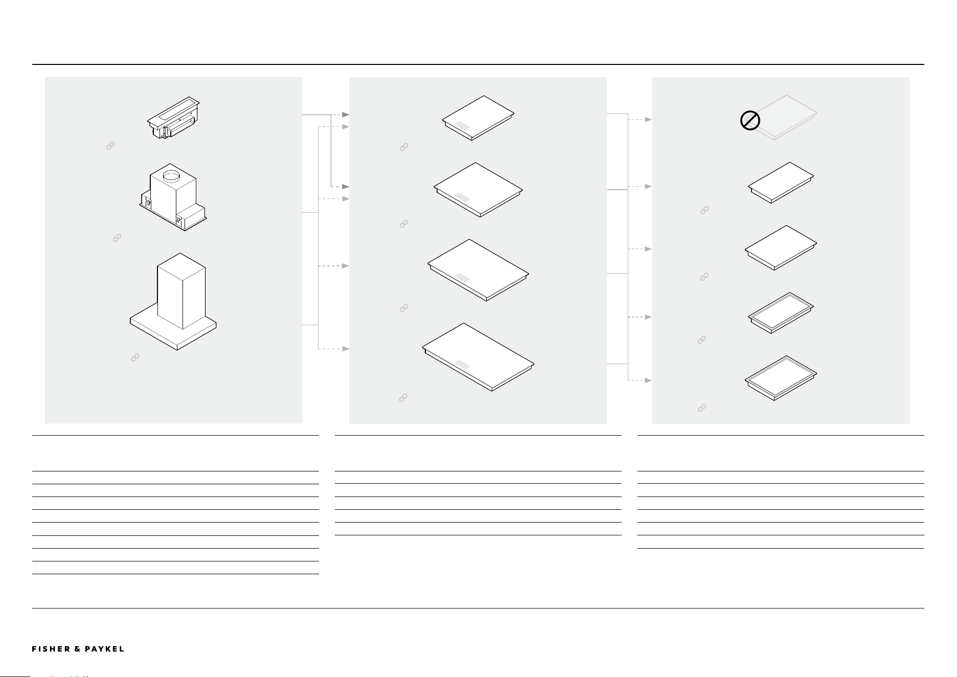
MODULAR SYSTEM PAIRING OVERVIEWPRODUCT DECISIONS | MODULAR HOBS
Primary Hobs have a touchscreen via which the Auxiliary Induction, Teppanyaki and
downdraft Ventilation modules are controlled.
It is optional to pair up to 2x Auxilliary Hobs with a Primary Hob. Auxilliary units do not
have an interface so must be installed with and controlled via a Primary module.
PRIMARY MODULAR HOBS Black Glass Grey Glass AUXILIARY MODULAR HOBS Black Glass Grey Glass
39cm Primary Induction Hob CI392DTTB1 CI392DTTG1 30cm Auxiliary Induction Hob CI302DB1 CI302DG1
60cm Primary Induction Hob CI604DTTB1 CI604DTTG1 39cm Auxiliary Induction Hob CI392DB1 CI392DG1
76cm Primary Induction Hob CI764DTTB1 CI764DTTG1 Stainless Steel
90cm Primary Induction Hob CI905DTTB1 CI905DTTG1 30cm Auxiliary Teppanyaki Hob CIT302DX1
39cm Auxiliary Teppanyaki Hob CI392DX1
39cm Primary Induction Hob
60cm Primary Induction Hob
76cm Primary Induction Hob
NO Auxiliary Hob
30cm Auxiliary Teppanyaki Hob
13cm Modular Auxiliary Downdraft
90cm Primary Induction Hob
39cm Auxiliary Teppanyaki Hob
30cm Auxiliary Induction Hob
39cm Auxiliary Induction Hob
Choose between downdraft or overhead ventilation, both of which are seemlessly
controlled by the Primary Hob. Auxiliary Modular Ventilation provides eecient venting to
39cm and 60cm Primary Hobs.
AUXILIARY MODULAR VENTILATION Black Glass Grey Glass
13cm Modular Auxiliary Downdraft, 300x70 ducting CD13DB1 CD13DG1
13cm Modular Auxiliary Downdraft, 222x89 ducting CD13DB2 CD13DG2
CONNECTED OVERHEAD VENTILATION Stainless Steel
60cm Integrated Insert Wall Cooker Hood HP60IHCB4
90cm Integrated Insert Wall Cooker Hood HP90IHCB4
90cm Box Chimney Wall Cooker Hood HC90BCXB4
Integrated Insert Cooker Hood
Wall Cooker Hood
<< CONTENTS

© FISHER & PAYKEL LIMITED 2026 PAGE 3290003269D EU UK IE PLANNING GUIDE MoDULAR HobS - VERSIoN D - MARCH 2026
PLANNING CONSIDERATIONS
© FISHER & PAYKEL LIMITED 2026 PAGE 3390003269D EU UK IE PLANNING GUIDE MoDULAR HobS VERSIoN D - MARCH 2026 PAGE 3390003269D EU UK IE PLANNING GUIDE MoDULAR HobS VERSIoN D - MARCH 2026
The models shown in this Planning Guide may not be available in all markets and are subject to change at any time. Product specifications may vary from those shown. This Planning Guide should not be used as installation guidance for any product. Further information is required to safely and correctly install the
products featured here. Specific installation guidance will be available with the product on delivery and on our website fisherpaykel.com
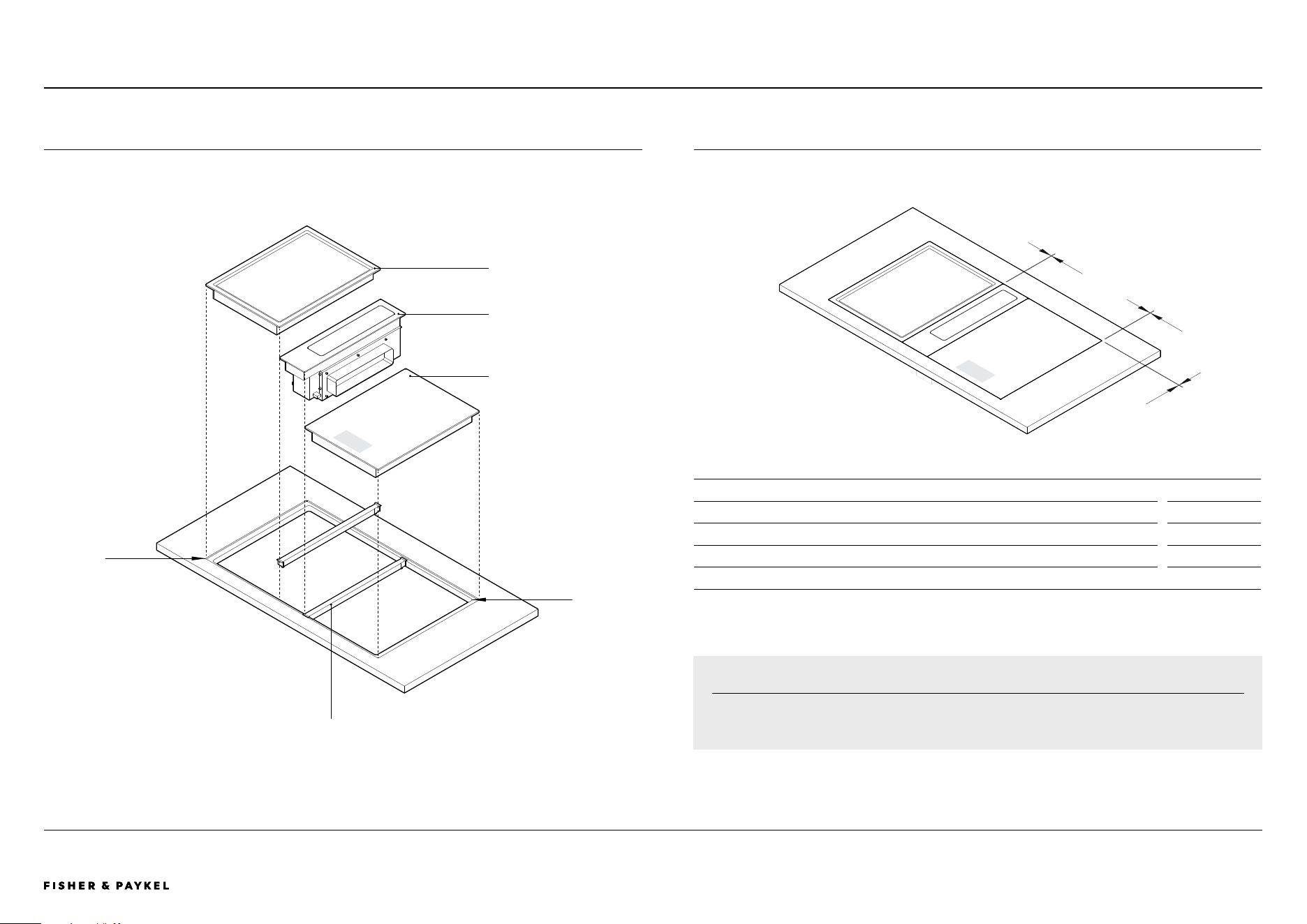
INSTALLATION DIMENSIONS
INSTALLATION DIMENSIONS mm
A Distance between modules 2
B Distance between edge of module and edge of recess 2
C Corner radii of cutout max 10
D Corner radii of recess 4
INSTALLATION OVERVIEW
INSTALLATION OVERVIEW
c
d
JOINER BAR
Required between modules,
supplied with auxiliary modules.
PRIMARY HOB
AUXILIARY DOWNDRAFT
AUXILIARY HOB
PLANNING CONSIDERATIONS | MODULAR HOBS
a
b
b
IMPORTANT NOTE
Cutout widths and radii may not be possible in certain benchtop materials. Please refer to benchtop
suppliers material specifications and fabrication parameters.
<< CONTENTS
© FISHER & PAYKEL LIMITED 2026 PAGE 3490003269D EU UK IE PLANNING GUIDE MoDULAR HobS VERSIoN D - MARCH 2026
The models shown in this Planning Guide may not be available in all markets and are subject to change at any time. Product specifications may vary from those shown. This Planning Guide should not be used as installation guidance for any product. Further information is required to safely and correctly install the
products featured here. Specific installation guidance will be available with the product on delivery and on our website fisherpaykel.com
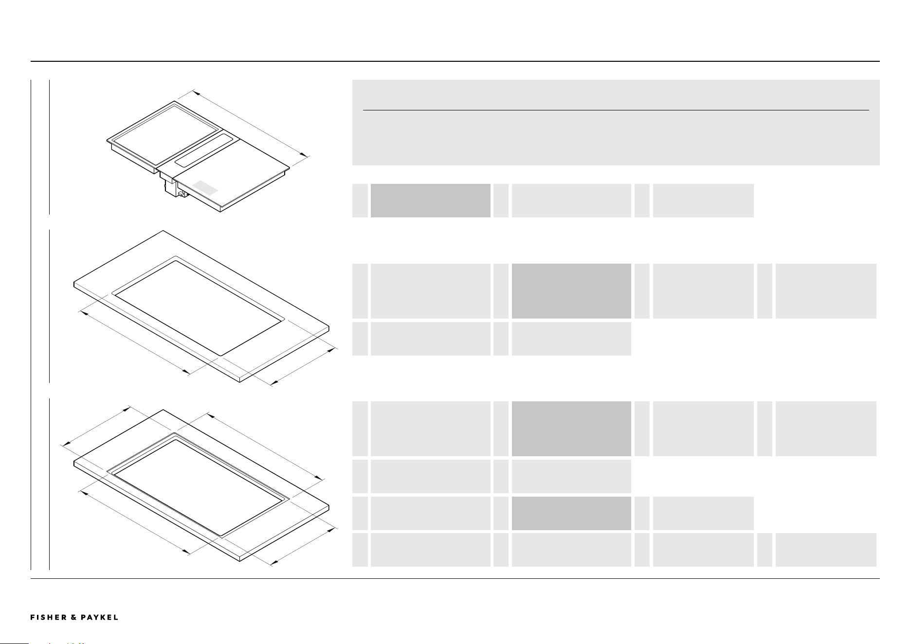
COMBINED INSTALLATION PLANNING
A
e
d
c
b
F
b
A
OVERALL WIDTH OF MODULES = COMBINED PRODUCT WIDTHS
add module widths
+ GAPS BETWEEN MODULES
2mm x (number of modules -1)
b
WIDTH OF CUTOUT
FLUSH AND PROUD
= OVERALL WIDTH OF MODULES - LEFT OVERHANG
19mm Induction / Teppanyaki
OR
16mm Downdraft
- RIGHT OVERHANG
19mm Induction / Teppanyaki
OR
16mm Downdraft
c
DEPTH OF CUTOUT
PROUD
= 507mm
b
WIDTH OF CUTOUT
FLUSH AND PROUD
= OVERALL WIDTH OF MODULES - LEFT OVERHANG
19mm Induction / Teppanyaki
OR
16mm Downdraft
- RIGHT OVERHANG
19mm Induction / Teppanyaki
OR
16mm Downdraft
d
DEPTH OF CUTOUT
FLUSH
= 509mm
e
WIDTH OF RECESS
FLUSH
= OVERALL WIDTH OF MODULES + 4mm
2mm each side
f
DEPTH OF RECESS
FLUSH
= 534mm = 530mm
product depth
+ 4mm
2mm top and bottom
COMBINED BENCHTOP EQUATIONS
Pairings of modular products have been designed to fit in a singular benchtop cutout. When grouping modules it is essential to calculate
their combined cutout requirements. The following equations can be used to guide calculations.
For dimensions of common configurations please refer to subsequent pages.
FLUSH PROUD MODULES
PLANNING CONSIDERATIONS | MODULAR HOBS
<< CONTENTS
© FISHER & PAYKEL LIMITED 2026 PAGE 3590003269D EU UK IE PLANNING GUIDE MoDULAR HobS VERSIoN D - MARCH 2026 PAGE 3590003269D EU UK IE PLANNING GUIDE MoDULAR HobS VERSIoN D - MARCH 2026
The models shown in this Planning Guide may not be available in all markets and are subject to change at any time. Product specifications may vary from those shown. This Planning Guide should not be used as installation guidance for any product. Further information is required to safely and correctly install the
products featured here. Specific installation guidance will be available with the product on delivery and on our website fisherpaykel.com
TYPICAL CONFIGURATIONS WITH AUXILIARY DOWNDRAFT
39cm
3
4
5
600
1 2
6
600 600600 600 600
900
600
39cm39cm 30cm 39cm 30cm
39cm 39cm 39cm
30cm 60cm 30cm
39cm 60cm 39cm
SINGLE - COMPACT <600
TWO IN A ROW - MID 900
THREE IN A ROW - WIDE >1200
THREE IN A ROW - EXTRA WIDE >1450
IMPORTANT NOTE
Other configurations are possible. Cutout widths may not be possible in certain benchtop materials.
Please refer to benchtop suppliers material specifications and fabrication parameters.
PRIMARY HOB
AUXILIARY HOB
AUXILIARY VENTILATION
1 SINGLE WITH AUXILIARY DOWNDRAFT - 39
Dimensions
W x D x H
Combined Module Size
517 x 530 x 180
Recess, flush
521 x 534 x 6.5
Cutout, flush*
482 x 509
Cutout, proud*
482 x 507
*Cutout width not central to overall width of modules. Oset specific to placement
of downdraft unit to the left or right. Side overhangs dier for downdraft and
Hob - downdraft 16mm, Hobs 19mm. Refer 'Benchtop Installation Details' for more
information.
2 TWO IN A ROW WITH AUXILIARY DOWNDRAFT- 39+39
Dimensions
W x D x H
Combined Module Size
904 x 530 x 180
Recess, flush
908 x 534 x 6.5
Cutout, flush*
862* x 509
Cutout, proud*
862* x 507
*Glass overhang at sides adjusted to fit 900mm cabinet. Dimensions specific
to 900 cabinet constructed from 19mm panels. 866W cutout recommended if
cabinetry construction allows.
3 THREE IN A ROW WITH AUXILIARY DOWNDRAFT - 39+30+30
Dimensions
W x D x H
Combined Module Size
1253 x 530 x 180
Recess, flush
1257 x 534 x 6.5
Cutout, flush
1215 x 509
Cutout, proud
1215 x 507
4 THREE IN A ROW WITH AUXILIARY DOWNDRAFT - 39+39+39
Dimensions
W x D x H
Combined Module Size
1423 x 530 x 180
Recess, flush
1427 x 534 x 6.5
Cutout, flush
1385 x 509
Cutout, proud
1385 x 507
5 THREE IN A ROW WITH AUXILIARY DOWNDRAFT - 60+30+30
Dimensions W x D x H
Combined Module Size
1468 x 530 x 180
Recess, flush 1472 x 534 x 6.5
Cutout, flush 1430 x 509
Cutout, proud 1430 x 507
6 THREE IN A ROW WITH AUXILIARY DOWNDRAFT - 60+39+39
Dimensions W x D x H
Combined Module Size
1638 x 530 x 180
Recess, flush 1642 x 534 x 6.5
Cutout, flush 1600 x 509
Cutout, proud 1600 x 507
PLANNING CONSIDERATIONS | MODULAR HOBS
<< CONTENTS
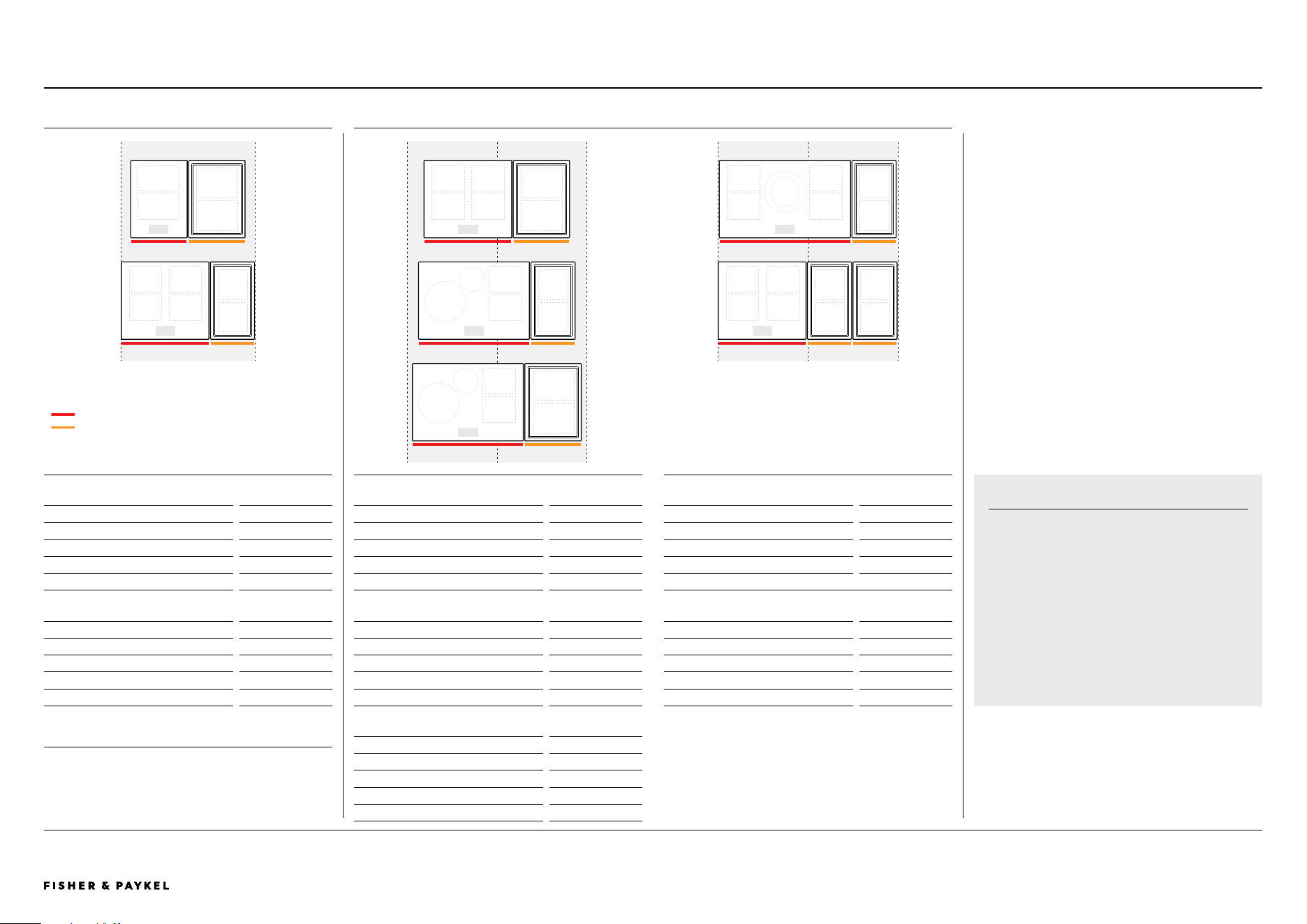
© FISHER & PAYKEL LIMITED 2026 PAGE 3690003269D EU UK IE PLANNING GUIDE MoDULAR HobS VERSIoN D - MARCH 2026 PAGE 3690003269D EU UK IE PLANNING GUIDE MoDULAR HobS VERSIoN D - MARCH 2026
The models shown in this Planning Guide may not be available in all markets and are subject to change at any time. Product specifications may vary from those shown. This Planning Guide should not be used as installation guidance for any product. Further information is required to safely and correctly install the
products featured here. Specific installation guidance will be available with the product on delivery and on our website fisherpaykel.com
TYPICAL CONFIGURATIONS WITH OVERHEAD VENTILATION
600 600
900
1 3
4
5
2
60cm 39cm39cm 39cm
60cm 30cm 76cm 30cm
76cm 39cm
MID <900 WIDE <1200
PRIMARY HOB
AUXILIARY HOB
600 600
6
7
60cm 30cm 30CM
90cm 30cm
IMPORTANT NOTE
Other configurations are possible.
Cutout widths may not be possible in certain
benchtop materials. Please refer to benchtop
suppliers material specifications and fabrication
parameters.
1 TWO IN A ROW - 39 + 39
Dimensions
W x D x H
Combined Module Size
772 x 530 x 74
Recess, flush 776 x 534 x 6.5
Cutout, flush 734 x 509
Cutout, proud 734 x 507
2 TWO IN A ROW - 60 + 30
Dimensions W x D x H
Combined Module Size
902 x 530 x 58
Recess, flush 906 x 534 x 6.5
Cutout, flush * 862* x 509
Cutout, proud * 862* x 507
*Glass overhang at sides adjusted to fit 900mm cabinet. Dimensions specific
to 900 cabinet constructed from 19mm panels. 866W cutout recommended if
cabinetry construction allows.
3 TWO IN A ROW - 60 + 39
Dimensions
W x D x H
Combined Module Size
987 x 530 x 74
Recess, flush
991 x 534 x 6.5
Cutout, flush
949 x 509
Cutout, proud
949 x 507
4 TWO IN A ROW - 76 + 30
Dimensions
W x D x H
Combined Module Size
1062 x 530 x 74
Recess, flush
1066 x 534 x 6.5
Cutout, flush
1024 x 509
Cutout, proud
1024 x 507
5 TWO IN A ROW - 76 + 39
Dimensions
W x D x H
Combined Module Size
1147 x 530 x 74
Recess, flush
1151 x 534 x 6.5
Cutout, flush
1109 x 509
Cutout, proud
1109 x 507
6 TWO IN A ROW - 90 + 30
Dimensions
W x D x H
Combined Module Size
1202 x 530 x 74
Recess, flush
1206 x 534 x 6.5
Cutout, flush
1164 x 509
Cutout, proud
1164 x 507
7 THREE IN A ROW - 60 + 30 + 30
Dimensions
W x D x H
Combined Module Size
1204 x 530 x 74
Recess, flush
1208 x 534 x 6.5
Cutout, flush
1166 x 509
Cutout, proud
1166 x 507
PLANNING CONSIDERATIONS | MODULAR HOBS
<< CONTENTS
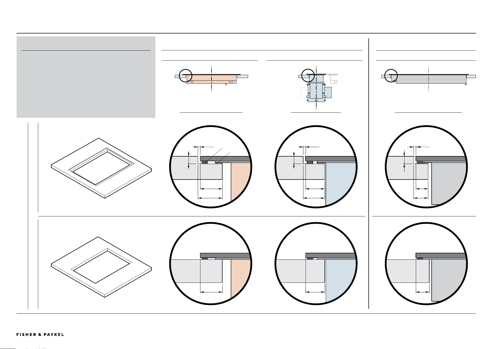
© FISHER & PAYKEL LIMITED 2026 PAGE 3790003269D EU UK IE PLANNING GUIDE MoDULAR HobS VERSIoN D - MARCH 2026
The models shown in this Planning Guide may not be available in all markets and are subject to change at any time. Product specifications may vary from those shown. This Planning Guide should not be used as installation guidance for any product. Further information is required to safely and correctly install the
products featured here. Specific installation guidance will be available with the product on delivery and on our website fisherpaykel.com
16mm
19mm
BENCHTOP INSTALLATION DETAILS
2mm
6.5mm
16mm
18mm
10.5mm
12.5mm
2mm
6.5mm
11.5mm
FRoNT VIEW PRoFILE VIEW FRoNT VIEW
SIDE OVERHANGS
INDUCTION + TEPPANYAKI MODULES DOWNDRAFT MODULE
FRONT + REAR OVERHANG
ALL MODULES
BENCH DETAIL
PROUD FLUSH
BENCHTOP INSTALLATION
A flush or proud finish between the top surface of the modules
and benchtop is achievable.
Some overhang details are common left to right or front to back,
however there are small dimensional changes between proud and
flush, cooking modules and ventilation module.
Care needs to be taken during planning and fabrication to ensure
successful installation of modules
Shimming may be required during flush installation.
2mm
6.5mm
19mm
21mm
TAPE
SHIM
PLANNING CONSIDERATIONS | MODULAR HOBS
<< CONTENTS
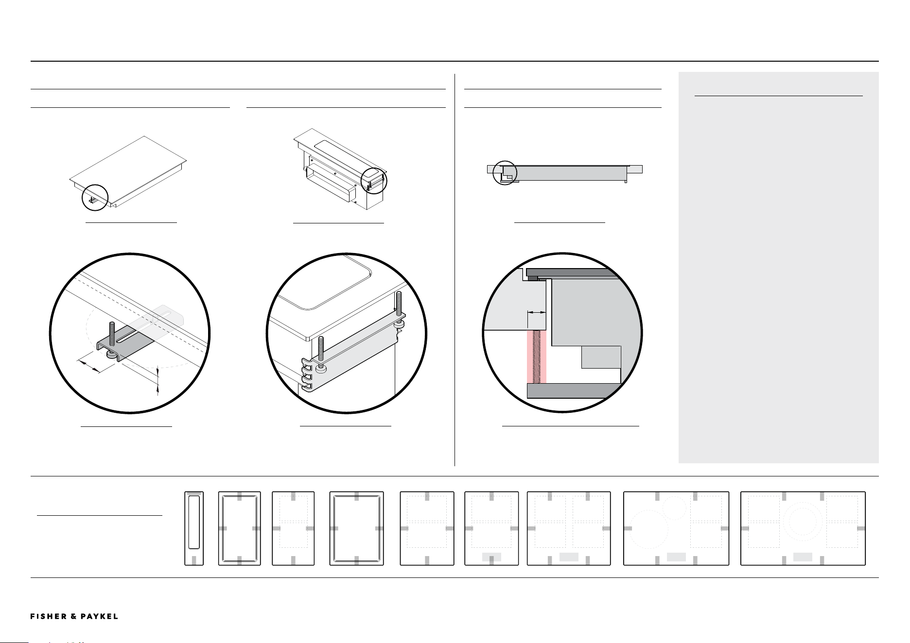
© FISHER & PAYKEL LIMITED 2026 PAGE 3890003269D EU UK IE PLANNING GUIDE MoDULAR HobS VERSIoN D - MARCH 2026 PAGE 3890003269D EU UK IE PLANNING GUIDE MoDULAR HobS VERSIoN D - MARCH 2026
The models shown in this Planning Guide may not be available in all markets and are subject to change at any time. Product specifications may vary from those shown. This Planning Guide should not be used as installation guidance for any product. Further information is required to safely and correctly install the
products featured here. Specific installation guidance will be available with the product on delivery and on our website fisherpaykel.com
CLAMPS
Clamps are suplied with modules to secure
their position to benchtop. There are two
types, common and rear downdraft.
It is recommended to have 10mm clearance
from edge of cutout for clamp engagement.
Clamps are attached to chassis at fixed
hole locations. A minimum of 2 clamps are
required per module, it is recommended they
are positioned on opposite sides of each
module eg. left and right or front and rear.
For more details please refer to Install Guide.
CLAMP FIXING LOCATIONS
PLAN VIEW
Minimum of 2 clamps per
module.
DETAIL A
Can be rotated and moved
horizontally
ISo FRoNT VIEW
ISo REAR VIEW
SIDE VIEW
CLEARANCE REQUIREMENTS
ALL MODULES
BRACKET TYPES
COMMON BRACKET REAR DOWNDRAFT BRACKET
Applies to all bracket locations, excluding rear downdraft
10mm
25mm
10mm
39cm 60cm30cm 76cm 90cm39cm 39cm30cm
DETAIL b
Bracket can be repositioned
vertically
A
B
C
DETAIL C
Minimum clearance common to all brackets
left/right and front/rear
CLAMPING LOCATIONSPLANNING CONSIDERATIONS | MODULAR HOBS
<< CONTENTS
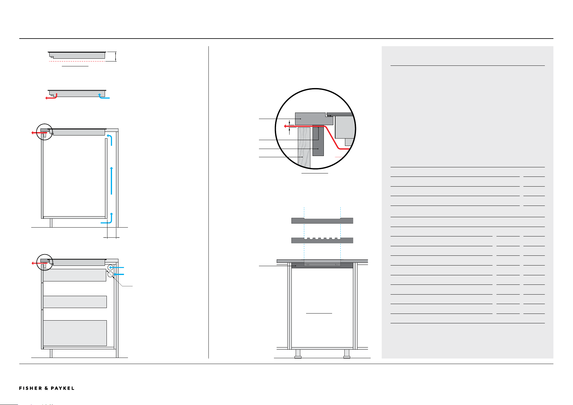
© FISHER & PAYKEL LIMITED 2026 PAGE 3990003269D EU UK IE PLANNING GUIDE MoDULAR HobS VERSIoN D - MARCH 2026
The models shown in this Planning Guide may not be available in all markets and are subject to change at any time. Product specifications may vary from those shown. This Planning Guide should not be used as installation guidance for any product. Further information is required to safely and correctly install the
products featured here. Specific installation guidance will be available with the product on delivery and on our website fisherpaykel.com
CABINETRY VENTILATION REQUIREMENTS
VENTILATION OVERVIEW
The cook modules require ventilation to allow cooling of the
electronic components within the chassis. Cooling fans are located
on the base of the product drawing cool air into the rear of the
product while hot air exits from vents at the front.
Provisions need to be made in cabinetry to allow fresh air to enter
and hot air to exit to ensure product ventilation and optimum
product performance.
When multiple products are installed their individual ventilation
requirements must also be combined.
CLEARANCE REQUIREMENTS mm
A Clearance below chassis from top of cook surface
- Induction 72
- Teppanyaki 86
VENTILATION REQUIREMENTS
INTAKE at rear mm cm
2
B via service channel, min depth 20 -
C through adjacent cabinets, per side wall* 2x Ø50 40
OUTLET at front* w x h cm
2
D 4mm gap along width of chassis
- 30cm cook module 255 x 4 10
- 39cm cook module 340 x 4 14
- 60cm cook module 555 x 4 22
- 76cm cook module 715 x 4 30
- 90cm cook module 855 x 4 34
* vents with equivalent-sized area possible. Must be positioned in front of product.
VENTILATION OUTLET
Hot air from cook modules must be able to exit at front of cabinets, the most
direct route is recommended.
The detail below shows one solution where cutouts have been made in the
support rail at front of cabinet, other routes are possible but must meet
dimensional guidelines in table.
VENTILATION REQUIREMENTS
Air intake at rear, outlet at front
CLEARANCE REQUIREMENTS
Modules require clearance
below chassis to ensure air flow.
A
FRONT REAR
INTAKE OPTION A:
SERVICE CHANNEL
Fresh air is drawn up from
the kick cavity through
service channel at rear of
cabinetry.
If cavities are tightly sealed,
ventilation holes in kick panel
are required.
INTAKE OPTION B:
ADJACENT CABINETS
2x Ø50 holes are required
in each side wall through to
adjacent cabinets. Total of x4
holes required.
b
c
SIDE VIEW
50mm
BENCHTOP
RAIL
FRONT PANEL
AIR VENT
D
DETAIL 1
SIDE VIEW
1
1
FRoNT VIEW
DATUM:
WIDTH OF CHASSIS
RAIL
Single cutout in rail, full width of
chassis, 4mm high.
Example of alternate cutout
where equivalent ventilation
area is achieved.
EXAMPLE VENTILATION CUTOUTS
PLANNING CONSIDERATIONS | MODULAR HOBS
<< CONTENTS
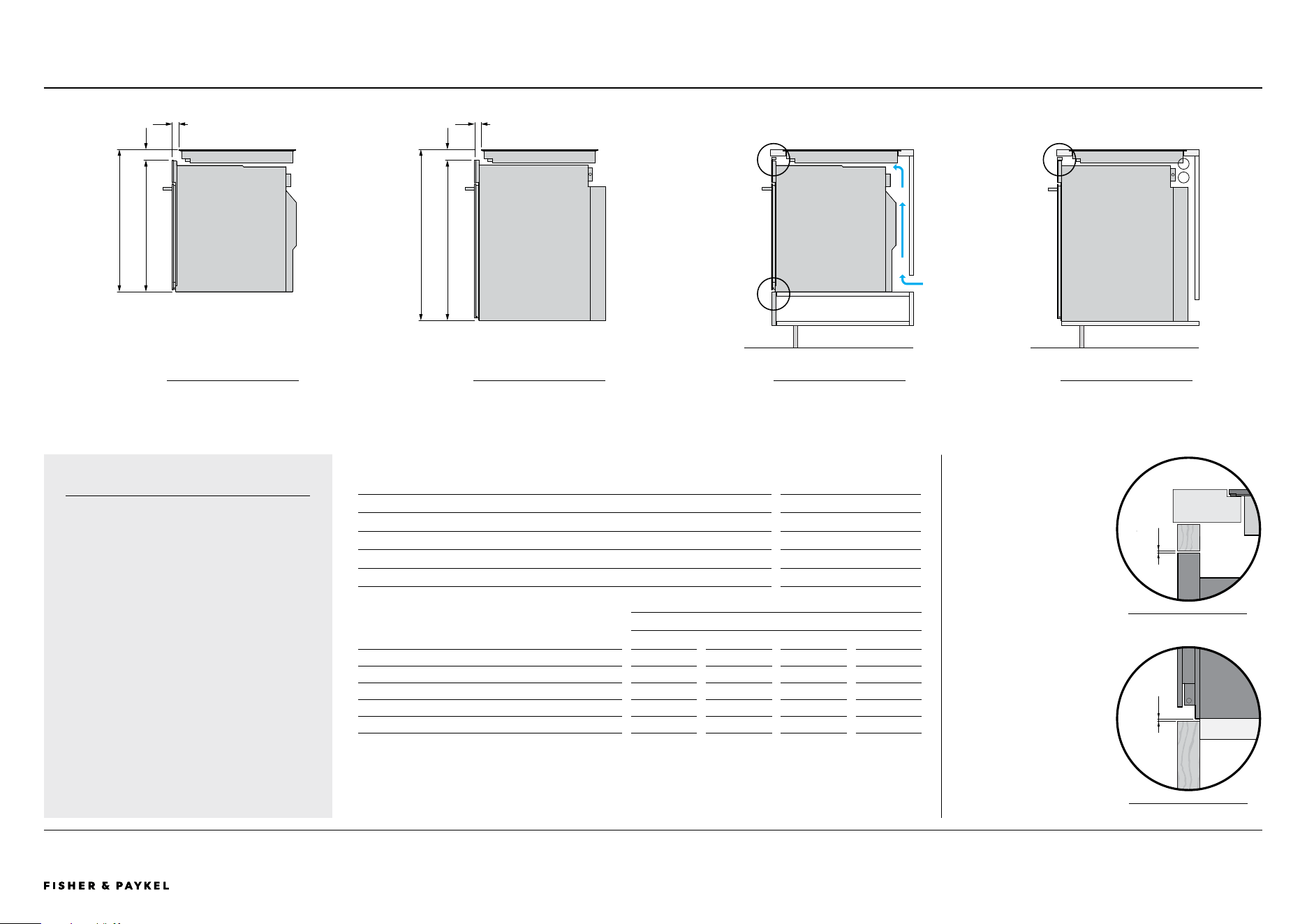
© FISHER & PAYKEL LIMITED 2026 PAGE 4090003269D EU UK IE PLANNING GUIDE MoDULAR HobS VERSIoN D - MARCH 2026 PAGE 4090003269D EU UK IE PLANNING GUIDE MoDULAR HobS VERSIoN D - MARCH 2026
The models shown in this Planning Guide may not be available in all markets and are subject to change at any time. Product specifications may vary from those shown. This Planning Guide should not be used as installation guidance for any product. Further information is required to safely and correctly install the
products featured here. Specific installation guidance will be available with the product on delivery and on our website fisherpaykel.com
HOB INSTALLATION WITH BUILT IN OVENSPLANNING CONSIDERATIONS | MODULAR HOBS
DETAIL 1 - ToP oF oVEN
2mm
DETAIL 2 - bASE oF oVEN
2mm
OVEN CLEARANCE TO
CABINETRY
A minimum vertical clearance
of 2mm is required between
ovens to benchtops or
cabinetry front panels. The
clearance above an oven
can contribute to ventilation
requirements of hobs (refer
previous page).
ba
INSTALLATION WITH OVENS
Fisher & Paykel 60cm and 76cm built in
ovens can be installed underneath modular
cooktops and extraction.
Hobs not included in this Planning Guide
may have dierent clearance requirements,
refer to their specific Guides.
Clearances to Fisher & Paykel ovens to not
apply to cabinetry, refer to Data Sheets for
clearances.
For complete oven specifications please
refer to specific Planning and Installation
Guides and CAD.
d
c
FISHER & PAYKEL OVEN DIMENSIONS mm
A Height of 60cm oven 598
Width of 60cm oven (not shown) 596
B Height of 76cm oven 729
Width of 76cm oven (not shown) 758
MODULES
INDUCTION TEPPANYAKI DOWNDRAFT GAS
OVEN UNDER MODULE DIMENSIONS
mm
mm
mm
mm
C Height from top of module to top of oven
min 49
min 63
min 177
min 53
D Overall height of 60cm oven and module
min 647
min 661
min 775
min 651
E Overall height of 76cm oven and module
min 778
min 792
min 906
min 782
F Distance from front of oven to front of module
min 30
min 30
min 30
min 30
MoDULE oVER 60CM oVEN MoDULE oVER 76CM oVEN MoDULE oVER 60CM oVEN
IN CAbINETRY
MoDULE oVER 76CM oVEN
IN CAbINETRY
Ventilation requiremnts
for modular products
and ovens can be
combined. Refer to
oven Planning and
Installation guides for
requirements.
1 1
2
c
e
f f
<< CONTENTS
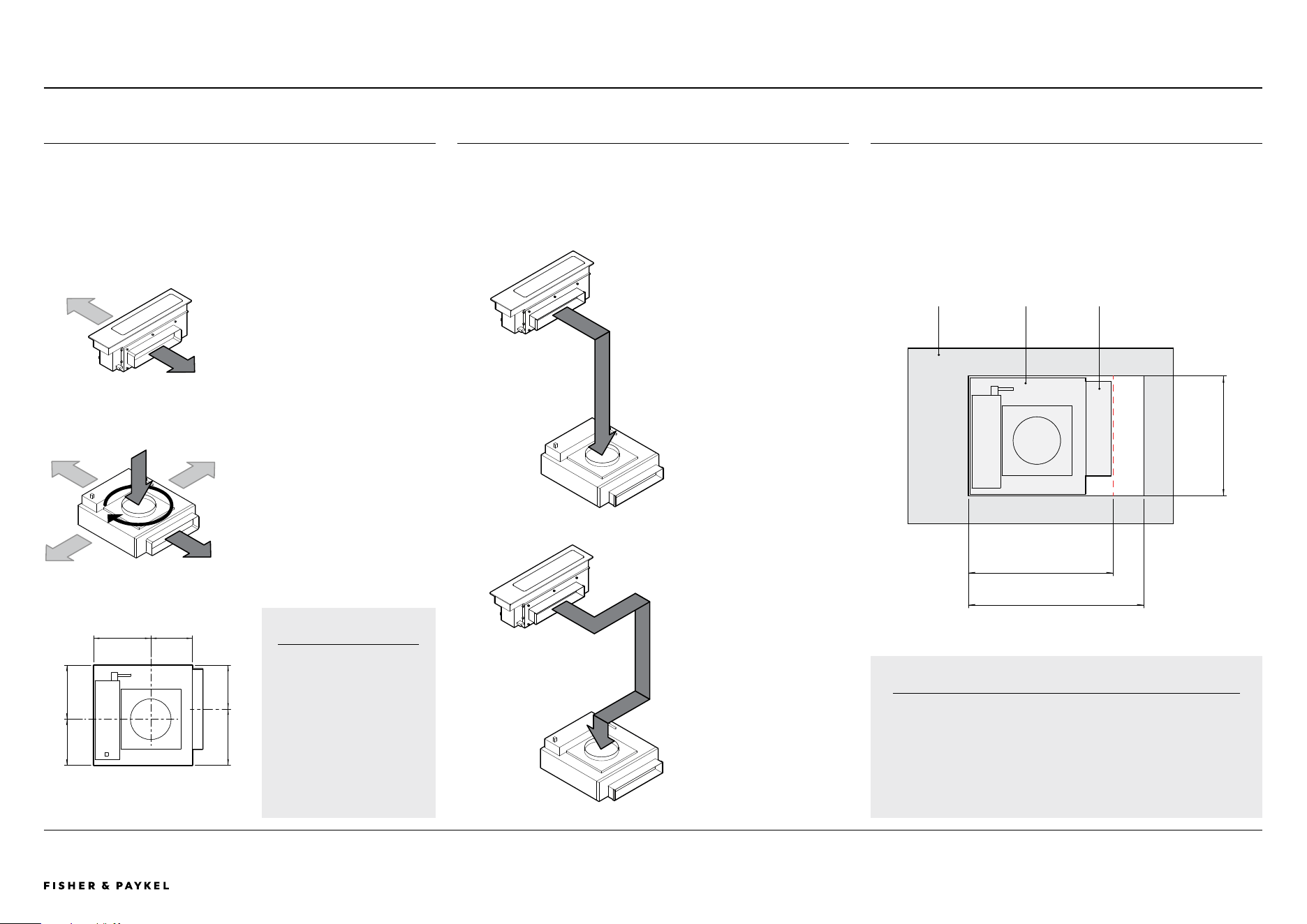
© FISHER & PAYKEL LIMITED 2026 PAGE 4190003269D EU UK IE PLANNING GUIDE MoDULAR HobS VERSIoN D - MARCH 2026
The models shown in this Planning Guide may not be available in all markets and are subject to change at any time. Product specifications may vary from those shown. This Planning Guide should not be used as installation guidance for any product. Further information is required to safely and correctly install the
products featured here. Specific installation guidance will be available with the product on delivery and on our website fisherpaykel.com
MODULAR AUXILIARY DOWNDRAFT COMPONENTS
470 MINIMUM
570 RECOMMENDED
390 MINIMUM
CABINETRY
FLOOR PANEL
BLOWERBOX
BLOWERBOX CUTOUT
The Blowerbox requires a minimum cutout of 390mm x 470mm in base
of cabinetry so it can be positioned on the floor.
For ease of installation and connection to outlet ducting it is
recommended that the cutout is increased to 390mm x 570mm.
CONNECTOR
MAINBOX
The mainbox can vent to the left or
right. The vent outlet can be secured
to either side of the mainbox during
installation.
BLOWERBOX
The blowerbox can be rotated 360°
around the intake, allowing the vent
outlet to be directed to suit.
MODULAR VENTILATION
Modular Downdraft consists of two units, a mainbox positioned in the
benchtop and a blower box positioned on the floor or subfloor. They are
connected via ducting. Ducting details can be found on subsequent
pages.
The direction of vent outlets on both units can be changed to suit
product placement and cabinetry layout.
OUTLET
IMPORTANT
Blowerbox inlet and
outlet are oset,
component is not
symmetrical (CD13DB1,
CD13DG1 outlet shown,
refer to datasheets for
more detail).
CARE TO BE TAKEN
WHEN PLANNING.
PLANNING CONSIDERATIONS | MODULAR HOBS
158
217
175
204
213
166
INTAKE
OUTLET
IMPORTANT
Depending on product placement and duct route blowerbox
might not be central to cabinet floor panel.
CARE TO BE TAKEN WHEN PLANNING.
For design planning and installation support please contact the
Fisher & Paykel design support team.
designsupport@fisherpaykel.com
TOP VIEW
SERVICE CHANNEL
Ducting routed through
service channel at rear of
cabinet or behind cabinet.
DIRECT
Minimal bends. Ducting
routed within cabinet.
DUCT ROUTING
Representational airflow showing indicative routing for ducting. The
distance between the mainbox and blower box is restricted by the 1.7m
length of the control cable connecting the two boxes. Refer to Sevices
page for connection locations.
TOP VIEW
<< CONTENTS
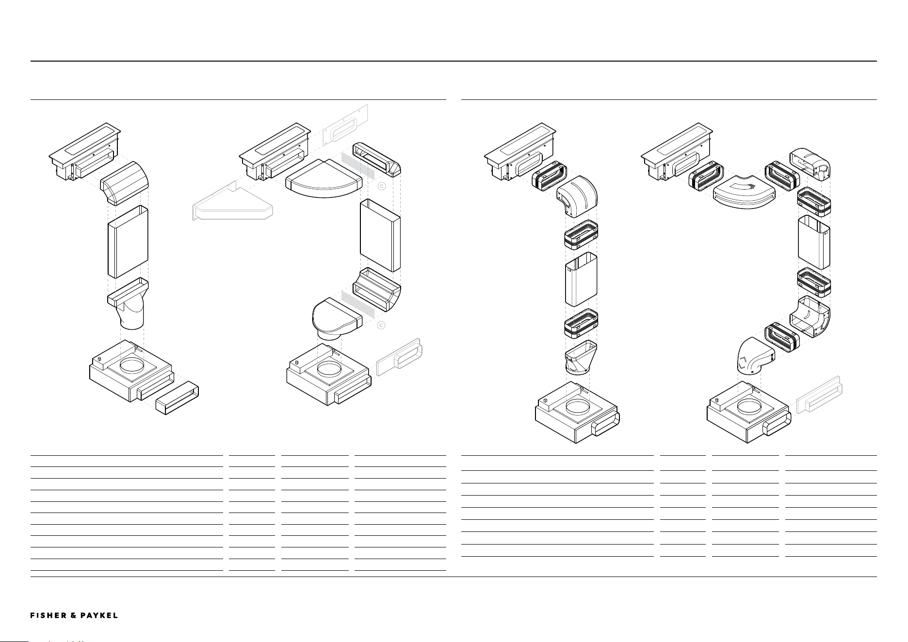
© FISHER & PAYKEL LIMITED 2026 PAGE 4290003269D EU UK IE PLANNING GUIDE MoDULAR HobS VERSIoN D - MARCH 2026 PAGE 4290003269D EU UK IE PLANNING GUIDE MoDULAR HobS VERSIoN D - MARCH 2026
The models shown in this Planning Guide may not be available in all markets and are subject to change at any time. Product specifications may vary from those shown. This Planning Guide should not be used as installation guidance for any product. Further information is required to safely and correctly install the
products featured here. Specific installation guidance will be available with the product on delivery and on our website fisherpaykel.com
CD13DB1 CD13DG1 MODULAR AUXILIARY DOWNDRAFT - 300x70 DUCTING
MODULAR AUXILIARY DOWNDRAFT DUCTING
Ducting Component
Supplied
Model supplied with
Optional Accessory Part No.
A Horizontal Elbow, 90°, 300x70*
x1
CD13DB1, CD13DG1
E90H30X7
B Vertical Elbow, 90°, 300x70*
x2
CD13DB1, CD13DG1
E90V30X7
C Duct, 1m, 300x70mm*
x1
CD13DB1, CD13DG1
D100X30X7
D Duct Adaptor, 150mm Diameter, 300x70mm*
x1
CD13DB1, CD13DG1
DA30X7D15
E Duct Adaptor, 90°, 150mm Diameter, 300x70mm*
x1
CD13DB1, CD13DG1
DA90D30X7D15
F Connector, 300x70*
x1
CD13DB1, CD13DG1
C30X7
G Outlet Adaptor, Mainbox, 222x89mm
OAD222X89
H Outlet Adaptor, Blower, 222x89mm
OAB222X89
I Horizontal Elbow, 90°, 300x70mm, Steel
E90H30X7S
CD13DB2 CD13DG2 MODULAR AUXILIARY DOWNDRAFT - 222x89 DUCTING
b
c
a
b
b
c
d
c
c
e
f
i
h
Ducting Component
Supplied
Model suppied with
Optional Accessory Part No.
J Duct Joiner Flexi 222x89*
x5
CD13DB2, CD13DG2
C222X89
K Duct 90 Bend Vertical 222x89*
x2
CD13DB2, CD13DG2
E90V222X89
L Duct 90 Bend Horizontal 222x89*
x1
CD13DB2, CD13DG2
E90H222X89
M Duct Straight Length 222x89*
x1
CD13DB2, CD13DG2
D1000X222X89
N Duct Adaptor 150 To 222x89*
x1
CD13DB2, CD13DG2
DA222X89D150
O Duct Adaptor 90 150 To 222x89*
x1
CD13DB2, CD13DG2
DA90D222X89D150
P Outlet Adaptor, Blower, 300x70mm
OAB300X70
* Component also available as an optional accessory
j
j
j
j
j
j
J
i
k
m
k
l
n
m
k
o
p
g
PLANNING CONSIDERATIONS | MODULAR HOBS
<< CONTENTS
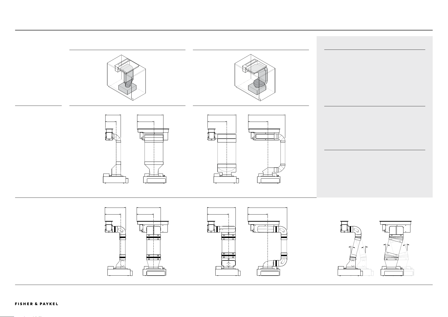
© FISHER & PAYKEL LIMITED 2026 PAGE 4390003269D EU UK IE PLANNING GUIDE MoDULAR HobS VERSIoN D - MARCH 2026
The models shown in this Planning Guide may not be available in all markets and are subject to change at any time. Product specifications may vary from those shown. This Planning Guide should not be used as installation guidance for any product. Further information is required to safely and correctly install the
products featured here. Specific installation guidance will be available with the product on delivery and on our website fisherpaykel.com
DIRECT DUCTING WITHIN CABINET DUCTING THROUGH SERVICE CHANNEL
300x70 DUCTING
CD13DB1 CD13DG1
222x89 DUCTING
CD13DB2 CD13DG2
273 435 475 615
345
395
475
655
197
280
320 330
265
280
355
330
DUCTING OVERVIEW
These are representational illustrations of modular
downdraft with ducting. Overall dimensions are
included. Other ducting layouts are possible.
Cabinetry may need to be adapted with features such
as cutouts, false panels, shelf and drawer
modifications to accommodate ducting.
DUCTING LENGTH
The distance between the mainbox and blower box is
restricted by the 1.7m length of the control cable
connecting the two boxes. Refer to Sevices page for
connection locations.
IMPORTANT
It is essential to work with CAD downloads of
Modular Downdraft components to design a ducting
layout best suited to specific cabinetry requirements.
For design planning and installation support please
contact the Fisher & Paykel design support team.
designsupport@fisherpaykel.com
15°
15°
15°
15°
MODULAR AUXILIARY DOWNDRAFT SYSTEM DIMENSIONSPLANNING CONSIDERATIONS | MODULAR HOBS
FRONT VIEW PROFILE VIEW FRONT VIEW PROFILE VIEW
FRONT VIEW PROFILE VIEW FRONT VIEW PROFILE VIEW FRONT VIEW PROFILE VIEW
DUCT JOINER FLEXI 222X89*
Joiners allow up 15° of movement
<< CONTENTS
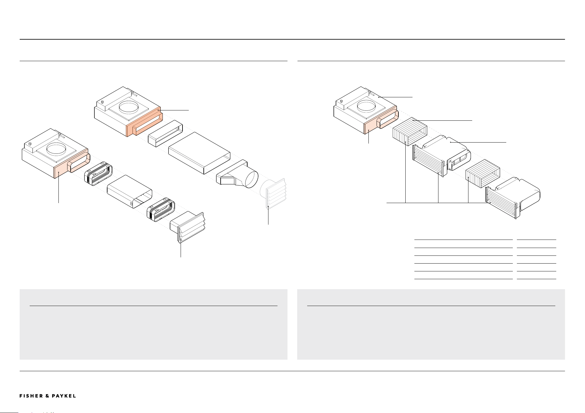
© FISHER & PAYKEL LIMITED 2026 PAGE 4490003269D EU UK IE PLANNING GUIDE MoDULAR HobS VERSIoN D - MARCH 2026
The models shown in this Planning Guide may not be available in all markets and are subject to change at any time. Product specifications may vary from those shown. This Planning Guide should not be used as installation guidance for any product. Further information is required to safely and correctly install the
products featured here. Specific installation guidance will be available with the product on delivery and on our website fisherpaykel.com
MODULAR AUXILIARY DOWNDRAFT VENTING OPTIONSPLANNING CONSIDERATIONS | MODULAR HOBS
DUCT OUT
OVERVIEW WITH DUCTING COMPONENTS
RECIRCULATED
OVERVIEW WITH RECIRCULATION KIT
BLOWERBOX
Can be reorientated for
alternate outlet direction.
FLEXIBLE DUCTING
Included with Recirculation Kit. Cut to length.
Straight 222x89 ducting can be used,
supplied with Modular Downdraft unit and as
optional accecessory C222X89.
FILTERBOX
For optimum performance it
is recommended to use the
two boxes supplied. A single
box can be used.
D RECIRCULATION KIT
Optional accessory, not all
components shown.
Filterbox can be orientated to exit
kick strip at front, rear or side.
OUTLET BLOWER 222x89
Included with CD13DB2 CD13DG2,
optional spare part
a for CD13DB1
CD13DG1
GRILLE, 150MM DIAMETER
Not supplied
CRITICAL NOTE
Indicative layouts, other configurations are possible. It is essential to work with CAD downloads of
modular ventilation components to design a ducting layout best suited to specific cabinetry
requirements.
For design planning and installation support please contact the Fisher & Paykel design support team.
designsupport@fisherpaykel.com
A
b
a
OUTLET BLOWER 300x70
Included with CD13DB1 CD13DG1,
optional spare part
b for CD13DB2
CD13DB2
OUTLET BLOWER 222x89
Included with CD13DB2 CD13DG2,
optional spare part
a for CD13DB1
CD13DG1
Optional Accessory
Part Number
A Outlet Adaptor, Blower, 222x89mm
OAB222X89
B Outlet Adaptor, Blower, 300x70mm
OAB300X70
C Outlet Grille, 222x89mm
DO-G-SS
D Recirculation Kit
KRCID834
RECIRCULATION KIT
The filter boxes of the Recirculation Kit fit within the toe kick cavity of cabinets. The vents need to be
positioned to allow venting of recirculated air into the room. Vents can be positioned in the kick strip,
at ends of cabinets or the rear of an island bench. Air must not be recirculated within the cabinetry.
For additional layout options and installation details refer to the Installation guide.
c OUTLET GRILLE, 222x89
Optional accessory.
<< CONTENTS
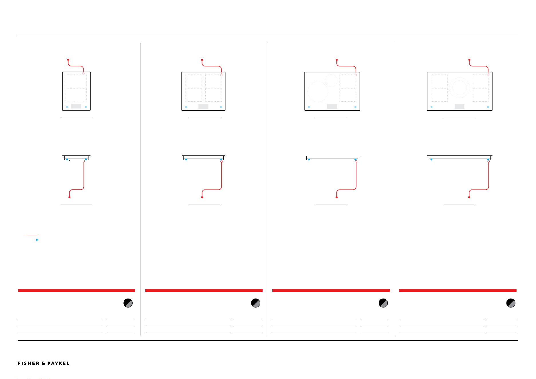
© FISHER & PAYKEL LIMITED 2026 PAGE 4590003269D EU UK IE PLANNING GUIDE MoDULAR HobS VERSIoN D - MARCH 2026 PAGE 4590003269D EU UK IE PLANNING GUIDE MoDULAR HobS VERSIoN D - MARCH 2026
The models shown in this Planning Guide may not be available in all markets and are subject to change at any time. Product specifications may vary from those shown. This Planning Guide should not be used as installation guidance for any product. Further information is required to safely and correctly install the
products featured here. Specific installation guidance will be available with the product on delivery and on our website fisherpaykel.com
SERVICES
PRIMARY MODULAR INDUCTION HOB, 39CM, 2
ZONES WITH SMARTZONE
Model no:
CI392DTTB1 Black
CI392DTTG1 Grey
Dimensions
mm
Power Cable
1700
PRIMARY MODULAR INDUCTION HOB, 60CM, 4
ZONES WITH SMARTZONE
Model no:
CI392DTTB1 Black
CI392DTTG1 Grey
Dimensions mm
Power Cable not supplied
PRIMARY MODULAR INDUCTION HOB, 76CM, 4
ZONES WITH SMARTZONE
Model no:
CI392DTTB1 Black
CI392DTTG1 Grey
Dimensions
mm
Power Cable
not supplied
PRIMARY MODULAR INDUCTION HOB, 90CM, 5
ZONES WITH SMARTZONE
Model no:
CI392DTTB1 Black
CI392DTTG1 Grey
Dimensions
mm
Power Cable
not supplied
FRoNT VIEW
ToP VIEW
FRoNT VIEW
ToP VIEW
FRoNT VIEW
ToP VIEW
FRoNT VIEW
ToP VIEW
POWER CABLE
COMMUNICATION PORT
PLANNING CONSIDERATIONS | MODULAR HOBS
<< CONTENTS
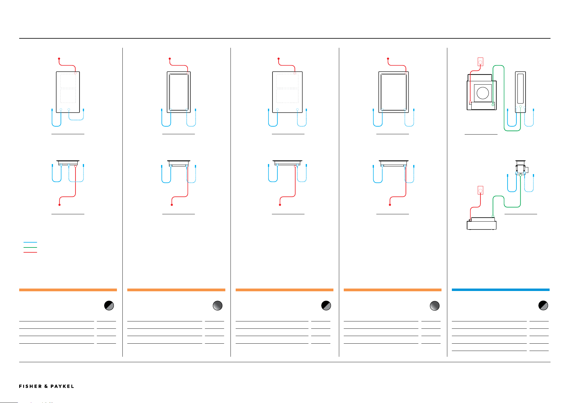
© FISHER & PAYKEL LIMITED 2026 PAGE 4690003269D EU UK IE PLANNING GUIDE MoDULAR HobS VERSIoN D - MARCH 2026
The models shown in this Planning Guide may not be available in all markets and are subject to change at any time. Product specifications may vary from those shown. This Planning Guide should not be used as installation guidance for any product. Further information is required to safely and correctly install the
products featured here. Specific installation guidance will be available with the product on delivery and on our website fisherpaykel.com
SERVICES
AUXILIARY MODULAR TEPPANYAKI HOB, 30CM,
2 ZONES
Model no:
CIT302DX1
Dimensions
mm
External Communication Harness*
500
Power Cable*
1700
* x1 supplied with each auxiliary unit
AUXILIARY MODULAR INDUCTION HOB, 30CM,
2 ZONES WITH SMARTZONE
Model no:
CI302DB1 Black
CI302DG1 Grey
Dimensions
mm
External Communication Harness*
500
Power Cable*
1700
* x1 supplied with each auxiliary unit
AUXILIARY MODULAR TEPPANYAKI HOB, 39CM,
2 ZONES
Model no:
CI392DX1
Dimensions
mm
External Communication Harness*
500
Power Cable*
1700
* x1 supplied with each auxiliary unit
AUXILIARY MODULAR INDUCTION HOB, 39CM, 2
ZONES WITH SMARTZONE
Model no:
CI392DB1 Black
CI392DG1 Grey
Dimensions
mm
External Communication Harness*
500
Power Cable*
1700
* x1 supplied with each auxiliary unit
AUXILIARY MODULAR VENTILATION, 13CM
Model no:
CD13DB1 Black, CD13DG1 Grey
CD13DB2 Black, CD13DG2 Grey
Dimensions
mm
External Communication Harness*
500
Central Communication Harness*
1700
Power Cable
3000
* x1 supplied with each auxiliary unit
FRoNT VIEW
ToP VIEW
FRoNT VIEW
ToP VIEW
FRoNT VIEW
ToP VIEW
FRoNT VIEW
ToP VIEW
FRoNT VIEW
ToP VIEW
EXTERNAL COMMUNICATION HARNESS
CENTRAL COMMUNICATION HARNESS
POWER CABLE
PLANNING CONSIDERATIONS | MODULAR HOBS
<< CONTENTS
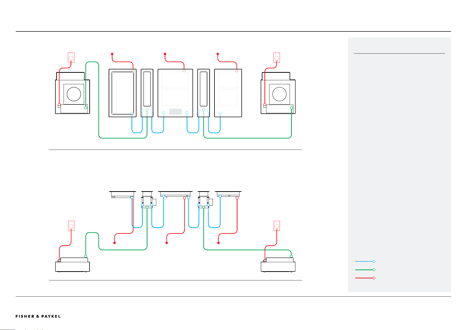
© FISHER & PAYKEL LIMITED 2026 PAGE 4790003269D EU UK IE PLANNING GUIDE MoDULAR HobS VERSIoN D - MARCH 2026
The models shown in this Planning Guide may not be available in all markets and are subject to change at any time. Product specifications may vary from those shown. This Planning Guide should not be used as installation guidance for any product. Further information is required to safely and correctly install the
products featured here. Specific installation guidance will be available with the product on delivery and on our website fisherpaykel.com
MODULAR CONNECTIONS
FRoNT VIEW
ToP VIEW
EXTERNAL COMMUNICATION HARNESS
CENTRAL COMMUNICATION HARNESS
POWER CABLE
SUPPLIED HARNESS
External communication harnesses connect
auxiliary modules to the primary module. These
connections must be to the product directly
adjacent in a 'daisy chain' configuration (refer
diagram).
1x External communication harness is supplied
with each auxiliary module (induction,
teppanyaki and downdraft ventilation).
1x Central communication harness is supplied
with auxiliary modular ventilation to connect
downdraft mainbox with blowerbox.
PLANNING CONSIDERATIONS | MODULAR HOBS
<< CONTENTS