P3 System Controllers
P3-050, P3-100, P3-150,
P3-200, P3-300
Quick Guide
TM
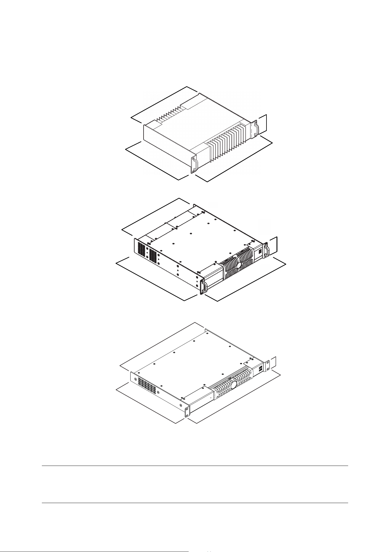
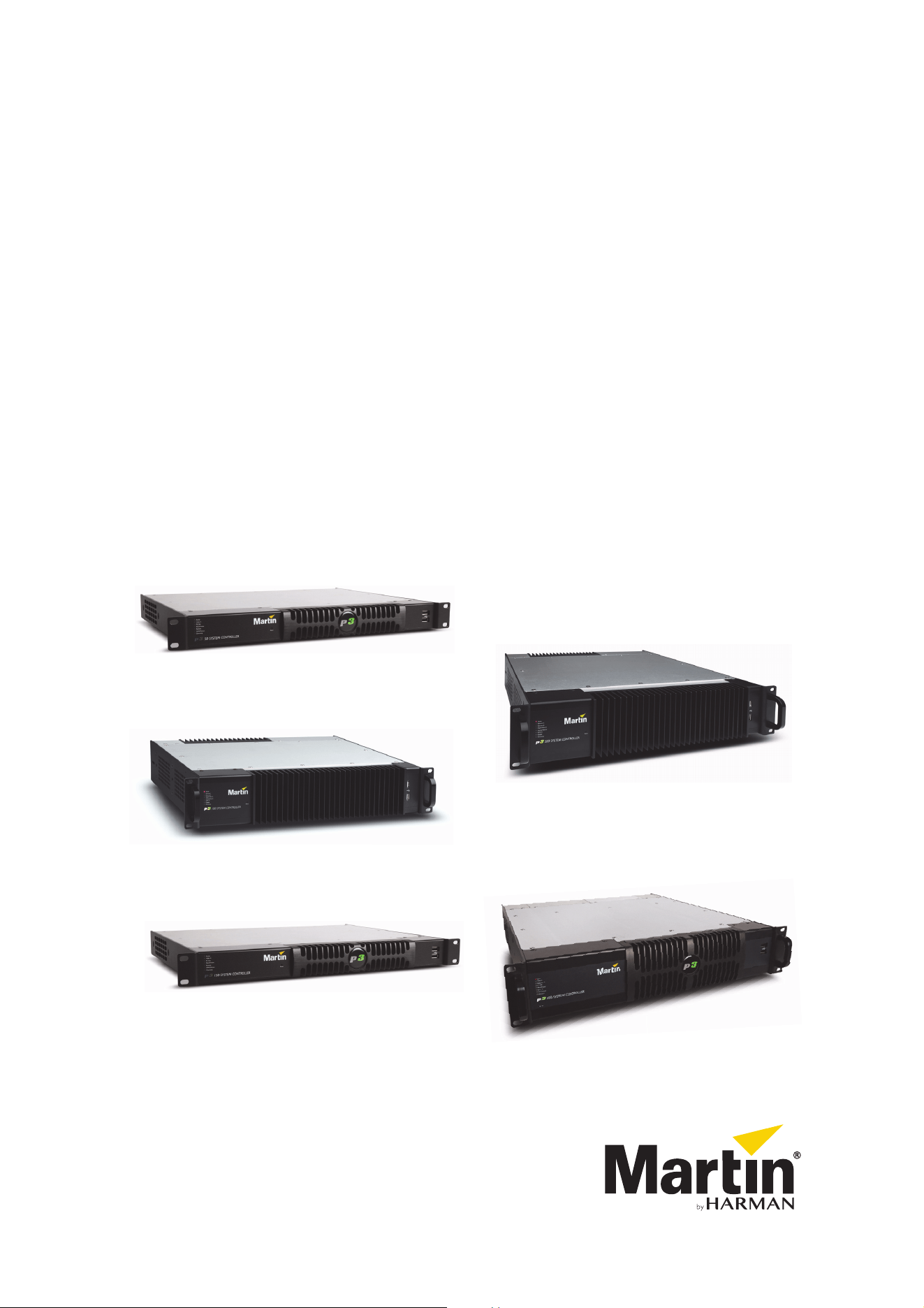
Dimensions
482
431
380
90
P3-100, P3-200
P3-300
All dimensions are in millimeters
P3-050, P3-150
482
431
343
45
90
431
508
482
©2009-2016 Martin Professional™ ApS. Information subject to change without notice. Martin Professional™ and all affiliated companies disclaim liability
for any injury, damage, direct or indirect loss, consequential or economic loss or any other loss occasioned by the use of, inability to use or reliance on
the information contained in this document. Martin™, Harman™ and all other trademarks in this document pertaining to services or products by Martin
Professional™ or its affiliates and subsidiaries are registered as the property of Harman International Industries.
P/N 35000226, Rev. G
Safety Information
The following symbols are used to identify important safety information on the product and in this manual:
This product is for professional use only. It is not for household use.
Read this guide before installing, powering or servicing this product, follow the safety precautions listed
below and observe all warnings in this guide and printed on the product.
If you have questions about how to operate this product safely, please contact your Martin supplier or call
the Martin 24-hour service hotline on +45 8740 0000, or in the USA on 1-888-tech-180.
PROTECTION FROM ELECTRIC SHOCK
• Connect the product to AC mains power within the following ranges only:
- P3-050: 100 - 240 V, 47 - 63 Hz
- P3-100: 115 - 250 V, 47 - 63 Hz
- P3-150: 100 - 240 V, 47 - 63 Hz
- P3-200: 115 - 250 V, 47 - 63 Hz
- P3-300: 100 - 240 V, 47 - 63 Hz
• Use only a source of AC mains power that complies with local building and electrical codes and has both
overload and ground-fault (earth-fault) protection.
• Ensure that the product is electrically connected to ground (earth).
• US, EU (Schuko) and UK power cables with IEC power input connectors are supplied with the product.
Connect the product to AC mains power using the cable that matches your local power outlet sockets. If
you need to replace the power plug to match any other type of power outlet socket, install a
grounding-type (earthed) listed power plug rated 5 A minimum as directed in this manual. In all cases,
check that the power plug connects correctly to ground (earth).
• Isolate the product from AC mains power if the power cable or power plug is in any way damaged,
defective or showing signs of overheating. Do not reapply power until the faulty item is replaced.
• For pluggable equipment, the socket outlet shall be installed near the equipment and shall be easily
accessible.
• Disconnect the product from AC mains power when not in use.
• There are no user-serviceable parts inside the product. Do not attempt to open the product. If service is
required, contact your Martin supplier or a Martin service partner.
• The product is for use in a dry location only. Protect it from moisture. Do not allow it to become wet.
WARNING!
Read the safety precautions in this section before
installing, powering, operating or servicing this
product.
Warning!
Safety hazard.
Risk of severe
injury or death.
Warning!
Refer to
manual before
installing,
powering or
servicing.
Warning!
Hazardous
voltage. Risk of
lethal or severe
electric shock.
Warning!
Fire hazard.
PROTECTION FROM FIRE
• Do not modify the product in any way.
• Do not operate the product if the ambient temperature (Ta) exceeds 50° C (122° F).
• Particular attention must be paid to cooling; under no circumstances should the airflow to the heat sinks
be restricted. A rack fan cooling unit to maintain the correct ambient temperature should be considered
when multiple units are stacked together.
• P3-100 and P3-200 controllers have a primary fuse in a fuseholder next to the mains power input socket.
If this fuse blows, replace it with a 2 AT (time delay) 250 V-rated 20 mm cartridge type only. Do not attempt
to bypass a fuse.
• The internal CR2032 lithium button cell battery must be replaced by Martin Professional™ or its
authorized service agents.
• Risk of explosion if battery replaced by incorrect type. Dispose of used batteries according to the
manufacturer’s instructions.
ATTENTION!
• En cas d'équipement enfichable, la prise doit être montée près de l'équipement et doit offrir un
accès facile.
• Il y a un danger d’explosion s’il y a un remplacement incorrect de batterie. Mettre au rebut les
batteries usagées conformément aux instructions du fabricant.

Contents
Dimensions . . . . . . . . . . . . . . . . . . . . . . . . . . . . . . . . . . . . . . . . . . . . . . . . . . . . . . . . . . . . . . . . . . . . . . . . 2
Safety Information. . . . . . . . . . . . . . . . . . . . . . . . . . . . . . . . . . . . . . . . . . . . . . . . . . . . . . . . . . . . . . . . . . 3
Introduction . . . . . . . . . . . . . . . . . . . . . . . . . . . . . . . . . . . . . . . . . . . . . . . . . . . . . . . . . . . . . . . . . . . . . . . . 6
Physical installation . . . . . . . . . . . . . . . . . . . . . . . . . . . . . . . . . . . . . . . . . . . . . . . . . . . . . . . . . . . . . . . . 7
System installation . . . . . . . . . . . . . . . . . . . . . . . . . . . . . . . . . . . . . . . . . . . . . . . . . . . . . . . . . . . . . . . . . 8
Connections: general. . . . . . . . . . . . . . . . . . . . . . . . . . . . . . . . . . . . . . . . . . . . . . . . . . . . . . . . . . . . . . . . 9
Connecting a P3 System Controller to AC mains power . . . . . . . . . . . . . . . . . . . . . . . . . . . . . . . . . . . . . 9
P3-050 and P3-150 connections and status . . . . . . . . . . . . . . . . . . . . . . . . . . . . . . . . . . . . . . . . . . . . . 11
P3-100 connections and status . . . . . . . . . . . . . . . . . . . . . . . . . . . . . . . . . . . . . . . . . . . . . . . . . . . . . . . 13
P3-200 connections and status . . . . . . . . . . . . . . . . . . . . . . . . . . . . . . . . . . . . . . . . . . . . . . . . . . . . . . . 15
P3-300 connections and status . . . . . . . . . . . . . . . . . . . . . . . . . . . . . . . . . . . . . . . . . . . . . . . . . . . . . . . 17
Service . . . . . . . . . . . . . . . . . . . . . . . . . . . . . . . . . . . . . . . . . . . . . . . . . . . . . . . . . . . . . . . . . . . . . . . . . . . 20
Fuse replacement (P3-100 and P3-200 only) . . . . . . . . . . . . . . . . . . . . . . . . . . . . . . . . . . . . . . . . . . . . 20
Air filter replacement . . . . . . . . . . . . . . . . . . . . . . . . . . . . . . . . . . . . . . . . . . . . . . . . . . . . . . . . . . . . . . . 20
Error codes . . . . . . . . . . . . . . . . . . . . . . . . . . . . . . . . . . . . . . . . . . . . . . . . . . . . . . . . . . . . . . . . . . . . . . 21
Updating and reloading P3 System Controller firmware . . . . . . . . . . . . . . . . . . . . . . . . . . . . . . . . . . . . 22
Internal battery. . . . . . . . . . . . . . . . . . . . . . . . . . . . . . . . . . . . . . . . . . . . . . . . . . . . . . . . . . . . . . . . . . . . 23
Troubleshooting. . . . . . . . . . . . . . . . . . . . . . . . . . . . . . . . . . . . . . . . . . . . . . . . . . . . . . . . . . . . . . . . . . . 24
Specifications . . . . . . . . . . . . . . . . . . . . . . . . . . . . . . . . . . . . . . . . . . . . . . . . . . . . . . . . . . . . . . . . . . . . . 25

6 P3 System Controller user manual
Introduction
This manual explains how to install and connect Martin Professional™ P3-050, P3-100, P3-150, P3-200™
and P3-300™ System Controllers to display video on an LED video installation that uses the P3 video signal
developed by Martin™. It gives important safety information for installers, technicians and operators.
For information about operating the P3 System Controller and displaying video on the installation, see the
user guides available for download from the P3 System Controller and video device support pages on the
Martin™ website at www.martin.com
For information about installing Martin™ video devices, see the user documentation supplied with devices
and available for download from the Martin™ website at www.martin.com
The latest firmware updates and user documentation for all Martin™ products are always available from the
Martin™ website.
Comments or suggestions regarding this user manual can be e-mailed to service@martin.dk or posted to:
Technical Documentation, Martin Professional A/S, Olof Palmes Allé 18, DK-8200 Aarhus N, Denmark.
Warning! Read “Safety Information” on page 3 before installing, powering or operating a P3
System Controller.
Thank you for selecting a product from the Martin P3 System Controller range.
Martin P3 System Controllers are video processors that let you set up and operate Martin LED-based video
display device installations working in a user-friendly interface. The controllers accept standard video signals
and distribute video to the installation using Martin’s P3 signal.
P3 System Controllers feature:
• Intuitive GUI (graphic user interface)
• DVI-D, SDI, HD-SDI, 3G-SDI, RGBHV, Component, S-Video and Composite video inputs
• Output pixel capacity expandable with additional P3 System Controllers
• Genlock
• Image rotation
•Scaling
• De-interlacing
• Gamma curve adjustment
• Real-time control via DMX and automation protocols
• Real-time color temperature and color space control
• Real-time preview of video input and mapped canvas
• Dynamic device remapping
• P3 System Controller Offline Editor (PC application that lets you prepare an installation layout offline)
Martin P3-PC™ software application
P3-PC™ is a Windows application available from Martin™ that can also be used in a P3 video display
system. P3-PC™ has four useful functions:
• You can use P3-PC™ as an offline editor for P3 system controllers. You can prepare show files offline on
your PC and then transfer them to a P3 system controller via a USB memory device.
• You can address LED Video panels, update panel firmware and run test patterns. You connect to the
panels via your PC’s network port.
• If you have a P3-PC™ license, you can also use P3-PC™ as a stand-alone P3 system controller and send
a P3 video signal from your PC directly to an array of Martin™ video panels containing up to 20 736 pixels
over an Ethernet cable. Video can be captured from your PC desktop. For this function to work, you must
insert a Martin One-Key™ USB dongle with a P3-PC™ license into a USB port on your PC.
• P3-PC can be installed directly on a Hippotizer media server to output P3 to up to 20 736 pixels. For this
function to work, you must insert a Martin One-Key™ USB dongle with a P3-PC™ license into a USB port
on a Hippotizer V4 (or newer) media server.

Physical installation 7
Physical installation
Martin Professional P3 System Controllers are designed to be rack-mounted in a central control location for
fixed installations or mounted in a flightcase rack for touring applications. The enclosure and 19” rack
mounting comply with IEC 60297. They can also simply be placed on a flat surface.
The unit has been qualified to operate in a dry environment within a temperature range of 0° C to 50° C
(32° F to 122° F). Do not operate the product in an ambient temperature above 50° C (122° F), or you may
cause damage that is not covered by the product warranty.
When rackmounting a P3 System Controller:
• Carefully review “Safety Information” on page 3.
• Check that the local AC power voltage is within the ranges listed on the P3 System Controller’s serial
number label.
• Fasten the product securely to the mounting rails in the rack using screws through all four of the holes
provided in the product’s front panel.
• Ensure adequate ventilation and free, unobstructed airflow around heatsinks.
• If multiple devices are installed in a rack, install a rack cooling fan if necessary to control ambient
temperature.
Mounting the P3-300
Besides front mounting using four screws through the front panel as described above, the P3-300™ must
also be held securely at the rear of the device by fastening it to a back rail or similar means of support. For
extra convenience, you can also install a rack slide kit.
To support the rear of the P3-300, use the M4 threaded holes provided in the sides of the housing to fasten
brackets or a rack slide kit to the P3-300. Respect the following precautions:
• Do not insert screws in the M4 threaded holes in the side of the housing any deeper than maximum 10
mm (0.4 inches) from the outer surface of the housing.
• Do not remove any of the existing screws from the housing of the P3-300.
• Do not drill new holes into the housing.
8 P3 System Controller user manual
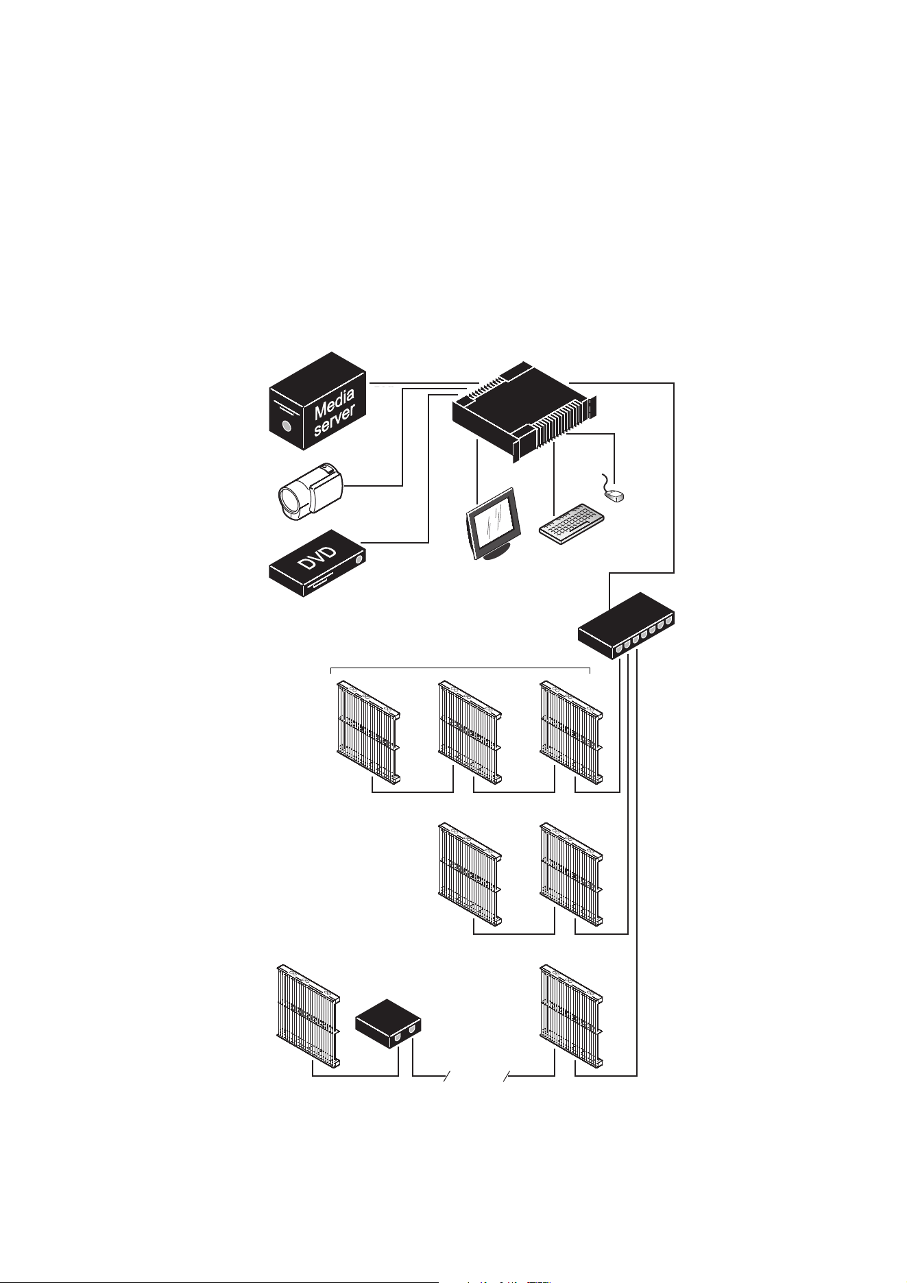
System installation
Example system layout
Figure 1 is a schematic diagram of how a system consisting of a P3 System Controller and Martin LC Plus™
LED video display panels should be laid out and connected. The diagram is given as an example only. For full
details of installing LED display devices – including important safety information – refer to the user
documentation supplied with devices and available for download free of charge from www.martin.com
Figure 1: System layout
DVI
DVI-D
Analog
video
Monitor
Mouse
Keyboard
P3 System Controller
P3 signal
1GB Ethernet
switch required
1GB Ethernet
switch required
100 m
Max. 50 panels per daisy-chain
if installation
exceeds 50 panels
if cable length
exceeds 100 m
cable
System installation 9
Connections: general
To connect the P3 System Controller and prepare it for use, see the system layout diagram in Figure 1 on
page 8 and see the connections panel information for the controller you want to connect later in this chapter.
Note that you must connect the Ethernet data cable from video display devices to the port marked Ethernet 2
or P3 (on the P3-100 and P3-200), the port marked P3 OUT (on the P3-050 and P3-150) or one of the ports
marked P3 OUT 1 - 4 (on the P3-300). Ports marked Ethernet 1, MGMT or EDMX cannot send a P3 signal to
video display devices.
Connecting a P3 System Controller to AC mains power
Warning! For protection from electric shock, the P3 System Controller must be electrically
connected to ground (earth). Power distribution circuits must be fitted with a current overload
fuse or circuit breaker and ground-fault (earth-fault) protection.
Warning! US, EU and UK power cables are supplied with the P3 System Controller. Use only the
cable that matches your AC mains power outlet or a power cable that is listed, 16 AWG or 1.5 mm
2
minimum and power connectors that are grounding-type (earthed), listed and rated 5 A minimum.
Warning! P3-100 and P3-200 controllers do not have a power on/off switch. They are powered on
as soon as mains power is applied to the power input connector and remain powered on until
mains power is shut down at source or disconnected from the P3 System Controller. The socket
or outlet used to supply the P3 System Controller with mains power must be located near the
device and easily accessible so that the device can easily be disconnected from power if
necessary.
Important! Connect the video source (media server, switcher, etc.), the P3 System Controller and
the LED video display installation to the same grounded/earthed power source to eliminate
ground/earth loop problems and avoid any differences in potential that may damage devices.
The P3 System Controller is mains powered via an internal fused power supply unit (PSU) that is compatible
with worldwide mains supply standards. However, to avoid differences in potential that may damage devices,
it must be connected to the same grounding-type (earthed) mains power outlet as the video source device
and LED video display installation it is connected to. Alternatively, appropriate steps must be taken to
eliminate differences in potential at different points in the installation. Martin Professional™ cannot be held
responsible for any damage caused if devices are not connected to AC mains power and ground/earth as
specified in this guide.
There is no power on/off switch on P3-100 and P3-200 controllers. Apply and shut down power using an
external switch at the power outlet or at the main switchboard. Do not apply power by inserting or removing
live power connectors, as this will cause arcing at the connector contacts that may damage devices and
connectors.
Important! Use the Shutdown button in the P3 System Controller software and allow the
software to close down before cutting power to the P3 System Controller.
Important! Do not shut down or disconnect power during a firmware update or while saving
a configuration file, as this will cause corruption of data that may make the P3 System Controller
inoperable.
Installing power plugs to match local power outlets
The P3 System Controller is supplied with three power cables that match US, European (Schuko) and UK
mains power sockets.
If these cables are not suitable, you will need to obtain a grounding-type (earthed) power cable rated 5 A
minimum with an IEC connector and a power plug that matches your local AC mains power outlet sockets.
Cables of this type are easy to obtain from computer hardware suppliers for example. Alternatively, you can
replace the power plug on one of the supplied power cables with a power plug of your local standard type. If
you do this, install a grounding-type (earthed) plug with an integral cable grip that is rated 5 A minimum and
follow the plug manufacturer’s instructions.
Ta b le 1 shows common wire color codes and pin identification

10 P3 System Controller user manual
symbols. If pins are not clearly identified, or if you have any doubts about proper installation, consult a
qualified electrician.
Wire color
(US color code)
Wire color
(EU color code) Pin Symbol Screw (US)
black brown live
L
yellow or brass
white blue neutral
N
silver
green yellow/green ground
(earth)
green
Table 1: Wire colors and pin identification

System installation 11
P3-050 and P3-150 connections and status
P3-050 and P3-150 connections panel
See Figure 2. The connections panels on the rear of the P3-050 and P3-150 are identical. The panel offers
the following features:
DMX In – For connection from a DMX source.
The DMX and RDM status LEDs light to indicate DMX and RDM activity respectively at this connector.
DMX Thru – For daisy-chaining of DMX signal to another device.
P3 Out – P3 signal output. Connect to the LED Video installation via an Ethernet cable. Can communicate
with an installation of LED video display devices containing a total of up to 100 000 pixels (P3-050) or
500
000 pixels (P3-150).
The P3 status LED lights to indicate P3 data activity at the connector.
DVI-D In – For digital video input.
The DVI status LED lights to indicate the presence of a valid signal.
DVI-D Thru – For daisy-chaining a DVI-D signal to another device.
Local UI – For connection of local user interface components:
• Two USB 2.0 ports for mouse, keyboard, USB memory device, etc.
• DisplayPort++ connector for connection to a DisplayPort, DVI (via adapter-cable), VGA (via adapter-cable)
or HDMI (via adapter-cable) monitor (SXGA 1280x1024 or better).
MGMT / EDMX – Management Network / EDMX Interface Port. Has several functions:
• Communication with P3-050 / P3-150's internal webserver for retrieval of status information.
• Connection to external syslog client for monitoring.
• Communication with remote user interface.
• Connection to a EDMX (Art-Net, sACN, etc.) source.
• Connection to a motion control (Kinesys K2, Tait Navigator, etc.) source.
This connector’s Link LED indicates the presence of a link, the Data LED indicates data activity at the
connector.
Mains Input – Male IEC socket, accepts AC mains power at 100 - 240 V, 47 - 63 Hz. A power on/off switch for
the System Controller is integrated into the IEC socket.
Figure 2: P3-050 and P3-150 connections panel
12 P3 System Controller user manual
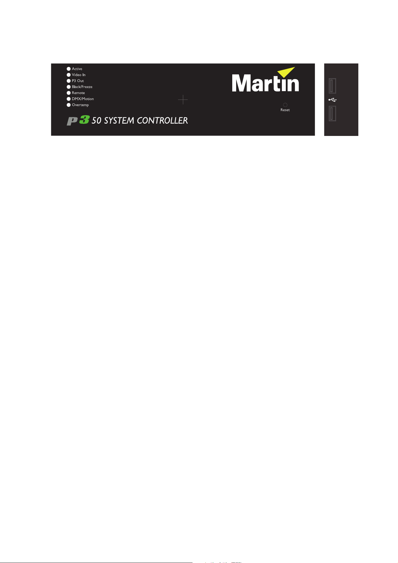
P3-050 and P3-150 front panel
See Figure 3. The LED status indicators, Reset button and USB ports on the front panel of the P3-050 and
P3-150 System Controllers are identical. They have the following functions:
Active flashes during startup and lights continuously during operation.
Video In indicates that the currently selected video input is valid.
P3 Out indicates that the P3-050 / P3-150 is sending a P3 data signal on its P3 output port.
Black/Freeze indicates that a Blackout or Freeze command is currently applied.
Remote indicates that the P3-050 / P3-150 is currently being controlled remotely by a P3 System Manager or
another P3-050 / P3-150.
DMX/Motion lights when a valid DMX, EtherDMX (Art-Net, sACN, etc.) or Motion Control (Kinesys K2, Tait
Navigator, etc.) signal is present at the DMX or EDMX Input connectors on the rear panel.
Overtemp flashes if the P3-050 / P3-150 is approaching maximum safe operating temperature. Overtemp
lights constantly if it has exceeded this temperature. A thermal protection circuit throttles down the processor
if the temperature is exceeded.
The Reset button lets you carry out a forced reset (if the System Controller’s P3 application freezes and you
cannot reboot the processor normally, for example). Use the tip of a ballpoint pen to push the button. The
System Controller constantly stores data in its onboard flash memory, so you are unlikely to lose data if the
application fails.
The two USB 2.0 ports on the front panel can be used for any USB peripheral including the keyboard and
mouse, but are most conveniently placed for portable memory devices. The keyboard and mouse can be
connected to the two USB ports on the rear connections panel.
Figure 3: P3-050 and P3-150 front panel (P3-050 illustrated)

System installation 13
P3-100 connections and status
P3-100 connections panel
See Figure 4. The connections panel on the rear of the P3-100 has the following features:
Two USB 2.0 ports – For mouse, keyboard, USB memory device, etc.
DVI Input – Accepts digital video input only (DVI-D).
Analog Inputs – Accept analog video. RCA-to-BNC or S-video-to-BNC adapters will be required if your
analog video cable does not have BNC connectors.
• Use the Y connector for composite video.
• Use the Y and C/Pb connectors for S-Video.
• Use the Y, C/Pb and Pr connectors for component video.
Typical connector color coding is Green to Y, Blue to Pb and Red to Pr.
DMX Input – Accepts a connection from a DMX source.
VGA Monitor – For connection to an analog monitor (SXGA 1280x1024 or better).
RS232 Serial – Not used.
Ethernet 1, MGMT – Management Network Port used for several functions:
• Communication with P3-100's internal webserver for retrieval of status information.
• Connection to external syslog client for monitoring.
• Communication with remote user interface.
• Connection to an EDMX (Art-Net, sACN, etc.) source.
• Connection to a Motion Control (Kinesys K2, Tait Navigator, etc.) source.
Ethernet 2, P3 – P3 signal output. Connect to the LED video installation via an Ethernet cable.
Mains Input – Male IEC socket, accepts AC mains power at 115 - 250 V, 47 - 63 Hz.
Fuseholder – Install a 2 A, T (time delay) slow-blow fuse only.
Figure 4: P3-100 connections panel
14 P3 System Controller user manual
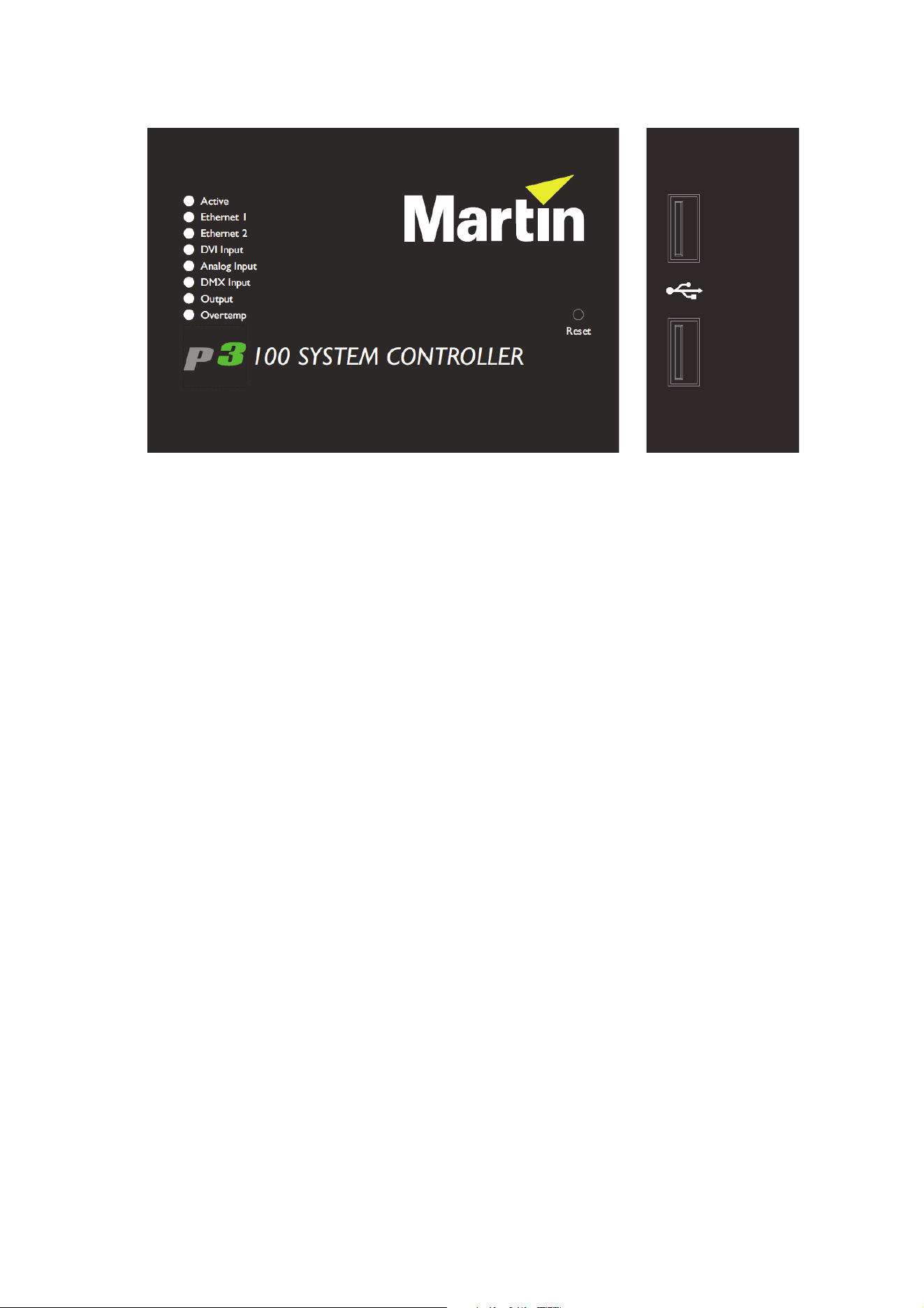
P3-100 front panel
See Figure 5. The LED status indicators and Reset button on the P3-100 front panel have the following
functions:
Active flashes during startup and lights continuously during operation.
Ethernet 1 indicates that there is activity on this connector on the rear panel (management port).
Ethernet 2 indicates that there is activity on this connector on the rear panel (P3 output port).
DVI Input indicates that DVI is currently selected as video input.
Analog Input indicates that analog video is currently selected as video input.
DMX Input indicates that a valid DMX signal is present at the DMX Input connector on the rear panel.
Output indicates that the P3-100 is sending a P3 data signal on its P3 output port.
Overtemp flashes if the P3-100 is approaching maximum safe operating temperature. Lights constantly if it
has exceeded this temperature. A thermal protection circuit throttles down the processor if the temperature is
exceeded.
The Reset button lets you carry out a forced reset (if the P3-100 application freezes and you cannot reboot
the processor normally, for example). Use the tip of a ballpoint pen to push the button. The P3-100 constantly
stores data in its onboard flash memory, so you are unlikely to lose data if the application fails.
The two USB 2.0 ports on the front panel can be used for any USB peripheral including the keyboard and
mouse, but are most conveniently placed for portable memory devices. The keyboard and mouse can be
connected to the two USB ports on the rear connections panel.
Figure 5: P3-100 front panel

System installation 15
P3-200 connections and status
P3-200 connections panel
See Figure 6. The connections panel on the rear of the P3-200 has the following features:
Two USB 2.0 ports – For mouse, keyboard, USB memory device, etc.
DVI Input – Accepts digital video input only (DVI-D).
SDI/HD-SDI In – accepts SDI, HD-SDI or 3G-SDI (Level A sync only) digital video input.
SDI/HD-SDI Thru – for SDI, HD-SDI or 3G-SDI (Level A sync only) digital video thru.
DMX Input – Accepts a connection from a DMX source.
VGA Monitor – For connection to an analog monitor (SXGA 1280x1024 or better).
RS232 Serial – Not used.
Ethernet 1: MGMT – Management Network Port used for several functions:
• Communication with P3-200's internal webserver for retrieval of status information.
• Connection to external syslog client for monitoring.
• Communication with remote user interface.
• Connection to an EDMX (Art-Net, sACN, etc.) source.
• Connection to a Motion Control (Kinesys K2, Tait Navigator, etc.) source.
Ethernet 2: P3 – P3 signal output. Connect to the LED video installation via an Ethernet cable.
Mains Input – Male IEC socket, accepts AC mains power at 115 - 250 V, 47 - 63 Hz.
Fuseholder – Install a 2 A, T (time delay) slow-blow fuse only.
Figure 6: P3-200 connections panel

16 P3 System Controller user manual
P3-200 front panel
See Figure 7. The LED status indicators and Reset button on the P3-200 front panel have the following
functions:
Active flashes during startup and lights continuously during operation.
Ethernet 1 indicates that there is activity on this connector on the rear panel (management port).
Ethernet 2 indicates that there is activity on this connector on the rear panel (P3 output port).
DVI Input indicates that DVI is currently selected as video input.
SDI Input indicates that SDI is currently selected as video input.
DMX Input indicates that a valid DMX signal is present at the DMX Input connector on the rear panel.
Output indicates that the P3-200 is sending a P3 data signal on its P3 output port.
Overtemp flashes if the P3-200 is approaching maximum safe operating temperature. Lights constantly if it
has exceeded this temperature. A thermal protection circuit throttles down the processor if the temperature is
exceeded.
Reset lets you carry out a forced reset (if the P3-200 application freezes and you cannot reboot the processor
normally, for example). Use the tip of a ballpoint pen to push the reset button. The P3-200 constantly stores
data in its onboard flash memory, so you are unlikely to lose data if the application fails.
The two USB 2.0 ports on the front panel can be used for any USB peripheral including the keyboard and
mouse, but are most conveniently placed for portable memory devices. The keyboard and mouse can be
connected to the two USB ports on the rear connections panel.
Figure 7: P3-200 front panel

System installation 17
P3-300 connections and status
P3-300 connections panel
See Figure 8. The connections panel on the rear of the P3-300 has the following features:
MGMT – Management Network Port. Has several functions:
• Communication with P3-300's internal webserver for retrieval of status information.
• Connection to external syslog client for monitoring.
• Communication with remote user interface.
This connector’s Link LED indicates the presence of a link, the Data LED indicates data activity at the
connector.
EDMX – Port for connection to various real-time show-integration interfaces:
• Connection to a EDMX (Art-Net, sACN, etc.) source.
• Connection to a Motion Control (Kinesys K2, Tait Navigator, etc.) source.
This connector’s Link LED indicates the presence of a link, the Data LED indicates data activity at the
connector.
Local UI – For connection of local user interface components:
• Two USB 2.0 ports for mouse, keyboard, USB memory device, etc.
• DisplayPort++ connector for connection to a DisplayPort, DVI (via adapter-cable), VGA (via adapter-cable)
or HDMI (via adapter-cable) monitor (SXGA 1280x1024 or better).
DVI-I In – For digital video input or analog video input (via BNC-to-DVI-A breakout cable).
This connector’s status LED indicates the presence of a valid signal.
Ref In – For connection to an external genlock source.
This connector’s status LED indicates the presence of a valid signal.
DVI-I Thru – For daisy-chaining of DVI-I signal to another device.
Ref Thru – For daisy-chaining of Ref signal to another device.
SDI A/B In – For SDI, HD-SDI or 3G-SDI digital video input. The two connectors can be used as two
independent inputs, or joined together into one Dual Link HD-SDI input.
This connector’s status LED indicates the presence of a valid signal.
SDI A/B Thru – For daisy-chaining of SDI signal(s) to another device.
SDI A/B Out – Not Used.
DisplayPort In – For DisplayPort digital video input (after installation of DisplayPort upgrade card).
This connector’s status LED indicates the presence of a valid signal.
Aux In – For future use (after installation of DisplayPort upgrade card).
DisplayPort Thru – For daisy-chaining of DisplayPort signal to another device (after installation of
DisplayPort upgrade card).
Figure 8: P3-300 connections panel
18 P3 System Controller user manual
Aux Thru – For future use (after installation of DisplayPort upgrade card).
DMX In – For connection from a DMX source.
DMX and RDM LEDs indicate corresponding activity on the connector.
DMX Thru – For daisy-chaining of DMX signal to another device.
P3 Out 1/2/3/4 – P3 signal outputs. Connect to the LED Video installation via Ethernet cables. Create up to 4
independent networks each containing maximum 500.000 pixels worth of LED video display devices.
These connectors’ Link LEDs indicate the presence of a link, the Data LEDs indicate data activity at the
connectors.
Mains Input – Male IEC socket, accepts AC mains power at 100 - 240 V, 47 - 63 Hz. A power on/off switch for
the P3-300 is integrated into the IEC socket.
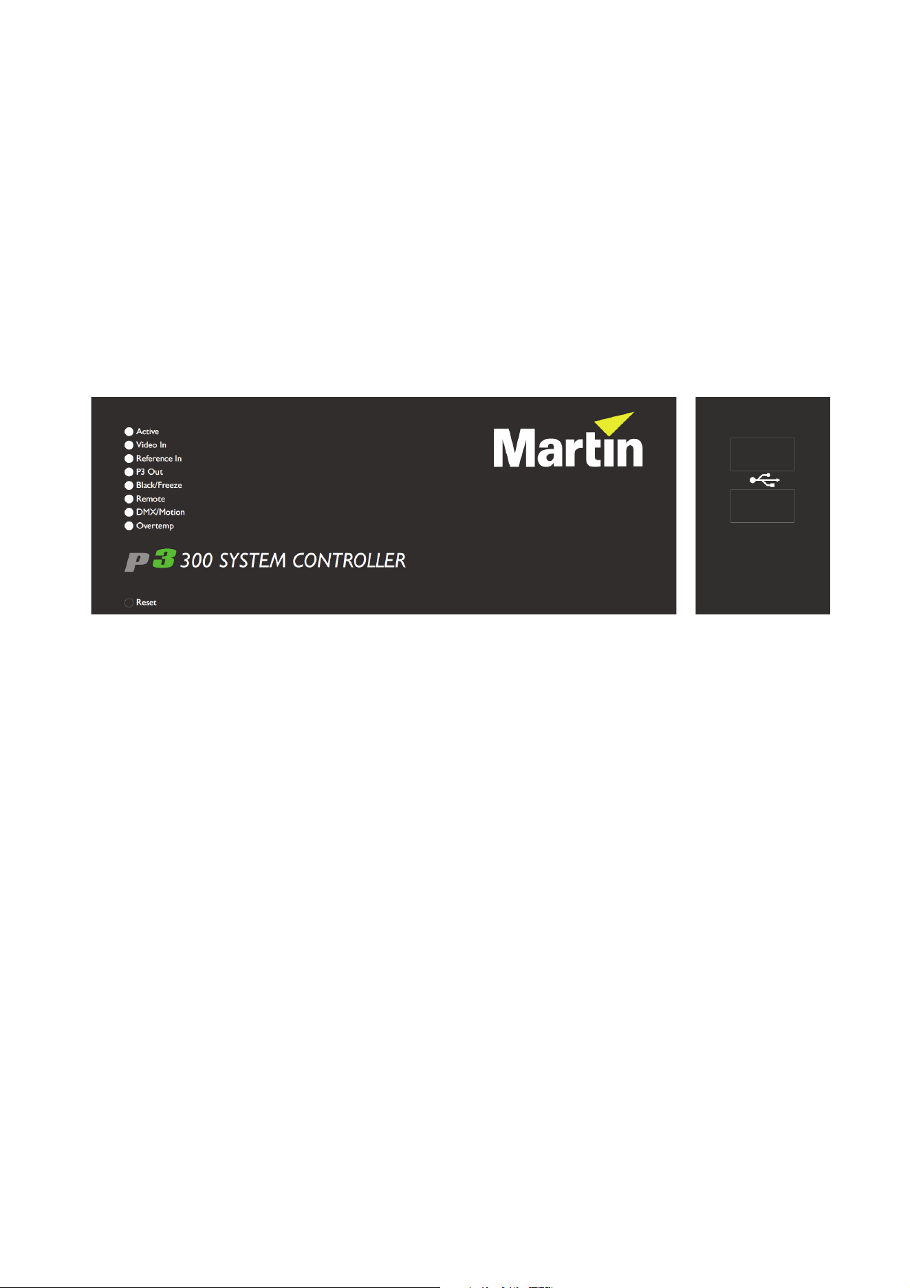
P3-300 front panel
See Figure 9. The LED status indicators and Reset button on the P3-300 front panel have the following
functions:
Active flashes during startup and lights continuously during operation.
Video In indicates that the currently selected video input is valid.
Reference In indicates that the currently selected sync reference is valid.
P3 Out indicates that the P3-300 is sending a P3 data signal on at least one of its four P3 output ports.
Black/Freeze indicates that a Blackout or Freeze command is currently applied.
Remote indicates that the P3-300 is currently being controlled remotely by a P3 System Manager or another
P3-300.
DMX/Motion lights when a valid DMX, EtherDMX (Art-Net, sACN, etc.) or Motion Control (Kinesys K2, Tait
Navigator, etc.) signal is present at the DMX or EDMX Input connectors on the rear panel.
Overtemp flashes if the P3-300 is approaching maximum safe operating temperature. Overtemp lights
constantly if it has exceeded this temperature. A thermal protection circuit throttles down the processor if the
temperature is exceeded.
The Reset button lets you carry out a forced reset (if the P3-300 application freezes and you cannot reboot
the processor normally, for example). Use the tip of a ballpoint pen to push the button. The P3-300 constantly
stores data in its onboard flash memory, so you are unlikely to lose data if the application fails.
The two USB 2.0 ports on the front panel can be used for any USB peripheral including the keyboard and
mouse, but are most conveniently placed for portable memory devices. The keyboard and mouse can be
connected to the two USB ports on the rear connections panel.
Figure 9: P3-300 front panel
System installation 19
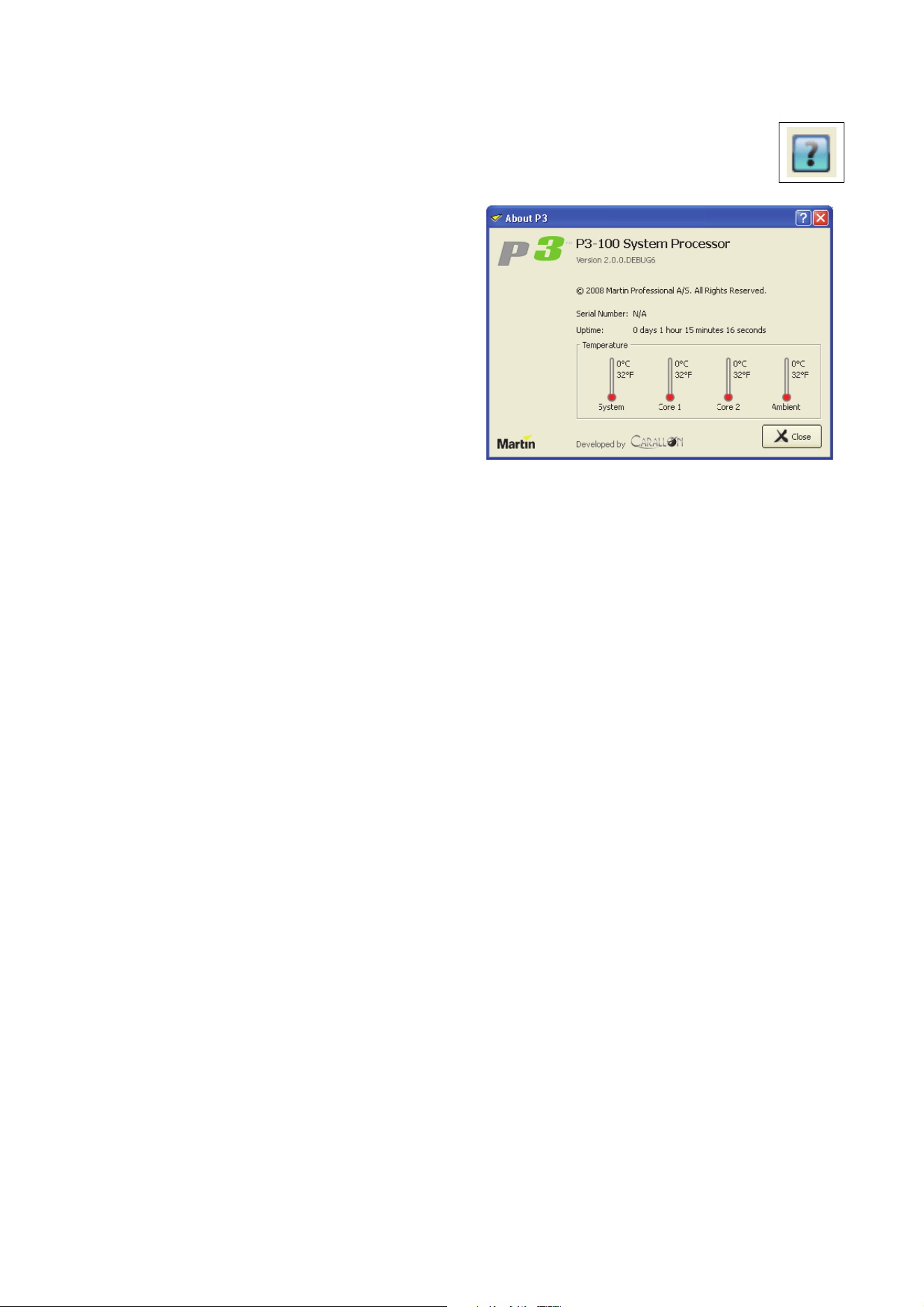
System status information
To view system status information, click on the blue question mark button in the bottom left of the
Hardware Settings window.
See Figure 10. The P3 System Controller’s
firmware version, serial number, uptime (resets
at power on) and hardware temperatures are
displayed in a pop-up window.
Figure 10: System and hardware info
20 P3 System Controller user manual
Service
There are no user-serviceable parts inside the P3 System Controller. Apart from the operations described
below, do not open any cover or attempt to modify or repair the unit. Doing so will void the product warranty.
Refer all service not described below to Martin Professional or its authorized service agents.
Fuse replacement (P3-100 and P3-200 only)
Warning! Disconnect the power cable before opening the fuseholder. Replace the fuse with one of
the same type and rating only.
P3-100 and P3-200 controllers have a user-replaceable main fuse in a fuseholder next to the mains power
inlet socket.
To replace a fuse:
1. Shut down power and disconnect the power cable.
2. Use a flat-bladed screwdriver to open the fuseholder.
3. Remove and test the main fuse. If it has blown, replace it with a 250 V-rated, T 2A (slow-blow) 20 mm
cartridge-type fuse only.
4. Reinstall the fuseholder and reconnect the power cable.
Air filter replacement
Warning! Disconnect the power cable before replacing the air filters. Replace with new items from
Martin™ only.
P3-050, P3-150 and P3-300 controllers have air filters in the cooling fan air intakes on the front face of the
unit. Check the filters regularly for signs of dirt, dust, condensate from smoke fluid, etc. and replace both the
filters at the same time with new items when any more than slight contamination is visible. The filters are
white to make it easy to see contamination. If you shine a light through the grill on the front of the unit, you
can check filters without having to remove them.
New air filters are available in packs of ten from Martin™ suppliers.
P3-050 and P3-150
Always replace P3-050 and P3-150 air filters as a pair.
To replace the air filters on a P3-050 or P3-150 system controller:
1. Switch off power at the IEC socket on the back of the controller and disconnect the power cable.
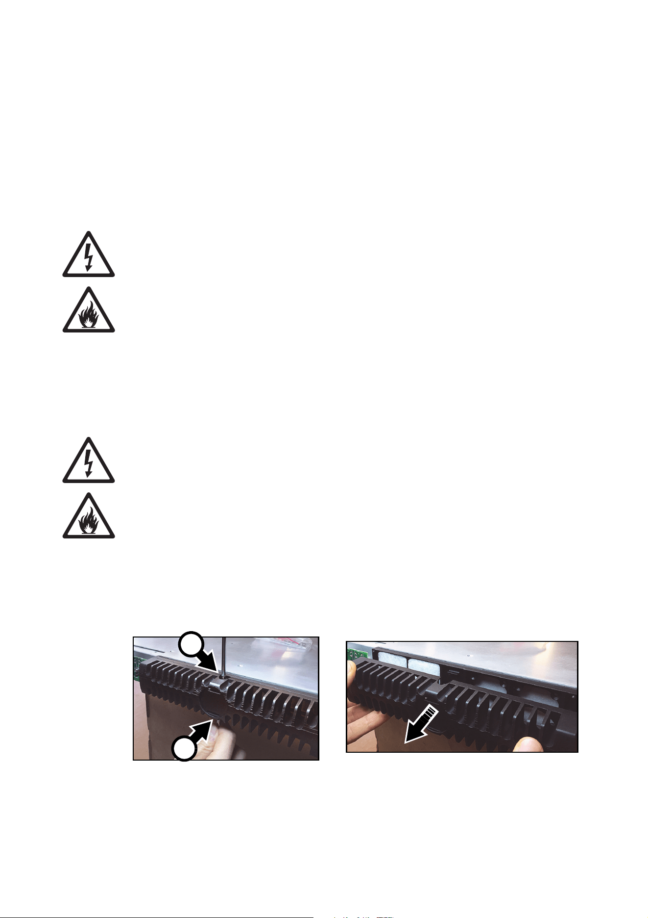
2. See Figure 11. Using two flat-bladed screwdrivers in the slots A in the center top and bottom of the fan
grill (arrowed), gently lever the internal clips to unhook them, then pull the fan grill off the controller.
Figure 11: Access to air filters, P3-050 / P3-150
A
A
Service 21
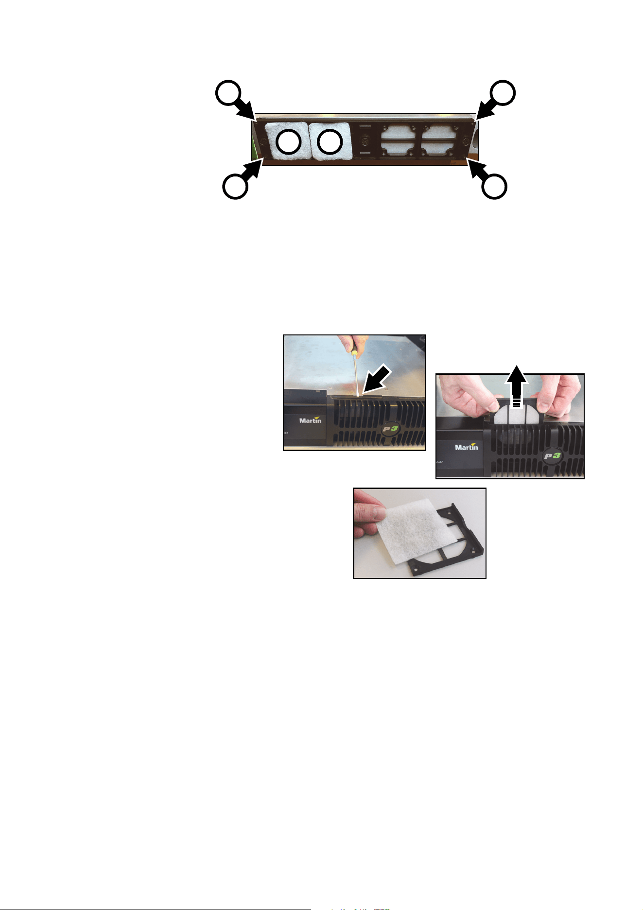
3. See Figure 12. Remove the used filters B and insert the new filters in their place.
4. Making sure that the filters stay in place and fully cover the air intake, hold the fan grill up to the front of
the controller and pass its four corner pins into their sockets C. Then press the center of the fan grill onto
the front of the controller until the internal clips hold it in place.
5. Check that the fan grill is held securely.
P3-300
To replace the air filters on a
P3-300:
1. Switch off power at the IEC
socket on the back of the unit
and disconnect the power
cable.
2. See Figure 13. Using a
flat-bladed screwdriver in the
slot provided (arrowed), lever
the filter holder up slightly, then
pull it vertically up and out of
the unit.
3. Remove the old filter and place
a new one in the filter holder.
4. Slide the filter holder back
down into the front of the unit,
making sure that the filter stays
in place and fully covers the air
intake.
5. Replace the other filter using
the same procedure.
Error codes
In the event of a system error, the LEDs on the front panel indicate error codes as follows. If LEDs flash a
pattern, there is a 1 second pause between patterns.
P3-050 and P3-150
System errors on the P3-300 are indicated by LEDs 2 and 3 lighting constantly with no light in the Active
LED, and then LEDs 4 to 7 flashing as follows:
• 4 flashes - No valid firmware.
• 5 flashes - Factory settings partition invalid.
Figure 12: Replacing air filters, P3-050 / P3-150
B
C
C C
C
B
Figure 13: Replacing an air filter, P3-300

22 P3 System Controller user manual
P3-100 and P3-200
Main board errors are indicated by the bottom four LEDs only flashing as follows:
• 2 flashes - Failed to power up main board
• 3 flashes - Firmware failed to boot
• 4 flashes - Power failed during boot
• 5 flashes - Power failed during normal operation
• 6 flashes - Watchdog timeout expired
Front panel errors are indicated by all LEDs flashing as follows:
• 1 flash - Invalid build version.
• 2 flashes - Unable to determine serial number.
• 3 flashes - SPI flash test failed.
• 4 flashes - Unable to perform front panel factory restore as factory firmware is corrupt.
• 5 flashes - Current front panel firmware is corrupt and there are no valid firmware versions available to
restore.
• 6 flashes - Restored front panel firmware is corrupt.
Front panel errors 1-3 may be generated by the bootloader or the main front panel firmware. Errors 4-6 may
only be generated by the bootloader.
P3-300
System errors on the P3-300 are indicated by LEDs 2 and 3 lighting constantly with no light in the Active
LED, and then LEDs 4 to 7 flashing as follows:
• 4 flashes - No valid firmware.
• 5 flashes - Factory settings partition invalid.
Updating and reloading P3 System Controller firmware
Important! Martin™ releases new firmware for P3 System Controller and P3 video display
products each time the firmware can be improved and new features added. Check the product
support pages on the Martin™ website at www.martin.com when you first receive the controller
and at regular intervals to make sure that the controller has the latest firmware installed. Check
firmware release notes carefully before you update firmware. A controller firmware version may
correspond to a specific video display device firmware version, and the correct firmware
versions may be required in all devices to ensure full compatibility.
Do not shut down or disconnect power while updating firmware in the P3 System Controller or video
panels, as this will corrupt the data and may make the P3 System Controller inoperable.
The P3 System Controller firmware can be reloaded – overwriting the existing firmware – if an update
becomes available or if you suspect that the firmware has become corrupted. The firmware is available for
download from the product support pages for the P3 System Controllers on the Martin website at
www.martin.com.
Service 23
To reload the firmware in a P3 System
Controller:
1. Download the latest firmware for
the controller from its product
support page on www.martin.com.
2. Copy the firmware to a USB
memory device.
3. Connect the USB memory device
to one of the P3 System
Controller’s USB ports.
4. Click on the Hardware Settings
button in the Tools menu.
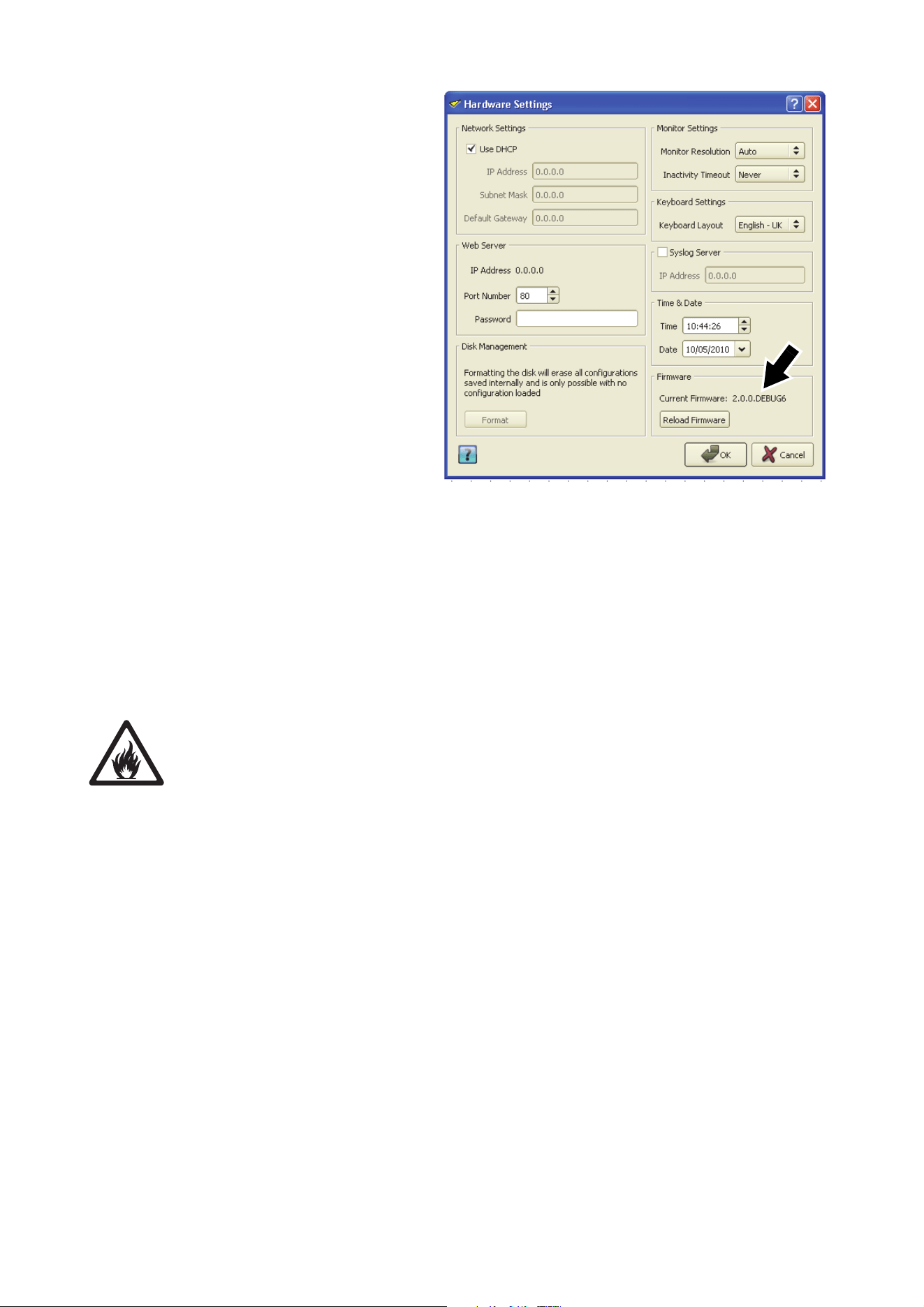
5. See Figure 14 (the Hardware
Settings window shown may vary
slightly depending on product and
firmware version installed, but the
procedure is basically the same).
The current firmware version is
displayed in the Firmware panel
(arrowed). Click on the Reload
Firmware button and browse to
the correct firmware file on the
USB memory device. Click on
Open and wait while data is
copied.
6. If the file is copied successfully, a dialog box opens asking you to restart the P3 System Controller. Click
on OK and wait while the P3 System Controller reboots on the new firmware. If the new firmware is
corrupted or incorrect, the P3 System Controller will return to the last valid firmware.
7. If the P3 System Controller firmware update is successful, update the firmware in the connected video
display devices if the firmware release notes tell you do this.
Internal battery
Warning! Risk of explosion if battery replaced by incorrect type. Refer to Martin Professional for
battery replacement.
P3 System Controllers have Renata CR2032 lithium button cell battery backup to maintain real-time clock
operation when the unit is not powered. Batteries should last for at least 10 years and can be replaced when
necessary. If you suspect that an internal battery is no longer providing backup power, contact Martin
Professional for replacement.
Figure 14: Firmware version and reloading firmware

24 P3 System Controller user manual
Troubleshooting
Problem Probable cause(s) Remedy
P3 System Controller is
completely dead.
No power to unit. Check power and connections.
Fuse blown (on P3-100 and P3-200 only,
located next to power input connector on
these models).
Disconnect power cable. Check fuse and replace.
One or more LED video display
devices shows video incorrectly
or does not show video at all.
Incorrect or faulty connection on P3 link.
Inspect connections and cables. Correct poor or
incorrect connections. Repair or replace damaged
cables.
Incorrect device addressing.
Check addressing setup in P3 System Controller
software.
Device defective.
Have faulty device serviced by Martin service
technician.
Other device (e.g. Ethernet switch) on P3 link
defective.
Replace with a device known to be operating
correctly. Have faulty device tested and serviced.
All devices and/or monitor
screen display video incorrectly
or do not display video at all.
Unusable video signal or defective video
source.
Check video source.
Fault on P3 link.
Inspect connections and cables. Correct poor
connections. Repair or replace damaged cables.
Device on P3 link defective.
Replace with a device known to be operating
correctly. Have faulty device tested and serviced.
P3 System Controller cuts out
(Overtemp LED gives warning)
Unit is too hot.
Ensure free airflow around unit.
Clean heatsinks on front and rear panels.
Check that ambient temperature does not exceed
max. permitted level.
Contact Martin for service.
Table 2: Troubleshooting

Specifications 25
Specifications
Physical
P3-050 / P3-150
Depth . . . . . . . . . . . . . . . . . . . . . . . . . . . . . . . . . . . . . . . . . . . . . . . . . . . . . . . . . . . . . . . . .360 mm (14.2 in.)
Width . . . . . . . . . . . . . . . . . . . . . . . . . . . . . . . . . . . . . . . . . . . . . . . . . . . . . . . . . . . . . . . . .482 mm (19.0 in.)
Height (rackmount 1U). . . . . . . . . . . . . . . . . . . . . . . . . . . . . . . . . . . . . . . . . . . . . . . . . . . . . .45 mm (1.8 in.)
Weight . . . . . . . . . . . . . . . . . . . . . . . . . . . . . . . . . . . . . . . . . . . . . . . . . . . . . . . . . . . . . . . . . 3.0 kg (6.7 lbs.)
P3-100 / P3-200
Depth . . . . . . . . . . . . . . . . . . . . . . . . . . . . . . . . . . . . . . . . . . . . . . . . . . . . . . . . . . . . . . . . .380 mm (15.0 in.)
Width . . . . . . . . . . . . . . . . . . . . . . . . . . . . . . . . . . . . . . . . . . . . . . . . . . . . . . . . . . . . . . . . .482 mm (19.0 in.)
Height (rackmount 2U). . . . . . . . . . . . . . . . . . . . . . . . . . . . . . . . . . . . . . . . . . . . . . . . . . . . . .90 mm (3.5 in.)
Weight . . . . . . . . . . . . . . . . . . . . . . . . . . . . . . . . . . . . . . . . . . . . . . . . . . . . . . . . . . . . . . . . 7.7 kg (17.0 lbs.)
P3-300
Depth . . . . . . . . . . . . . . . . . . . . . . . . . . . . . . . . . . . . . . . . . . . . . . . . . . . . . . . . . . . . . . . . .508 mm (20.0 in.)
Width . . . . . . . . . . . . . . . . . . . . . . . . . . . . . . . . . . . . . . . . . . . . . . . . . . . . . . . . . . . . . . . . .482 mm (19.0 in.)
Height (rackmount 2U). . . . . . . . . . . . . . . . . . . . . . . . . . . . . . . . . . . . . . . . . . . . . . . . . . . . . .90 mm (3.5 in.)
Weight . . . . . . . . . . . . . . . . . . . . . . . . . . . . . . . . . . . . . . . . . . . . . . . . . . . . . . . . . . . . . . . . 9.0 kg (19.8 lbs.)
P3-PC
Consists of software or software with USB only
Control/User Interface
P3-050 / P3-150
User interface. . . . . . . . . . . . . . . . . . . . . . SXGA (1280 x 1024) or better monitor (VGA, DVI, HDMI or DP),
USB keyboard, USB mouse
P3-100 / P3-200
User interface. . . . . . . . . . . . . . . . . . . . . . . . . . . . . . . . . . . . .SXGA (1280 x 1024) or better monitor (VGA),
USB keyboard, USB mouse
P3-300
User interface. . . . . . . . . . . . . . . . . . . . . . SXGA (1280 x 1024) or better monitor (VGA, DVI, HDMI or DP),
USB keyboard, USB mouse
P3-PC
User interface. . . . . . . . . . . . . . . . . . . . . . . . . . . . . . . . . . . . . . . . . . . . . . . . . . . . . PC hardware dependent
All models (except P3-PC)
Device status . . . . . . . . . . . . . . . . . . . . . . . . . . . . . . . . . . . . . . . . . . . . . . . . . . . . . . . Status indicator LEDs
Minimum System Requirements
P3-PC
PC running Windows XP, Vista 7, 8, 8.1 or 10 32/64 bit
Intel Core processor
1024 MB RAM (3 GB recommended)
100 MB available hard disk space
Display with 1280x1024 resolution or better
USB 1.1 (or higher) port for Martin One-Key™
Full administrator rights on PC
Gigabit Ethernet port for P3 output

26 P3 System Controller user manual
Video Processing
All models
System processing depth . . . . . . . . . . . . . . . . . . . . . . . . . . . . . . . . . . . . . 16 bit per color (48 bit per pixel)
Latency between first and last LED video display device . . . . . . . . . . . . . . . . . . . . . . . . . . . . . . . . . . None
Image rotation
Scaling (global and mixed pixel pitch)
De-interlacing
Gamma curve selection and adjustment
Real-time video content remapping
Real-time color temperature and color space control
Real-time preview of video input and mapped canvas
P3-050
Controller output capacity . . . . . . . . . . . . . . . . . . . . . . . . . 100 000 pixels (expandable by adding P3-050s)
Controller fixture capacity . . . . . . . . . . . . . . . . . . . . . . . . . .1 000 fixtures (expandable by adding P3-050s)
Maximum workspace area. . . . . . . . . . . . . . . . . . . . . . . . . . . . . . . . . . . . . . . . . . . . . . . . . .2 073 600 pixels
Maximum active capture area . . . . . . . . . . . . . . . . . . . . . . . . . . . . . . . . . . . . . . . . . . . . . . .2 073 600 pixels
System latency, DVI . . . . . . . . . . . . . . . . . . . . . . . . . . . . . . . . . . . . . . . . . . . . . . . . . . . . . . . . . . . . . 2 frames
P3-100
Controller output capacity . . . . . . . . . . . . . . . . . . . . . . . . . 500 000 pixels (expandable by adding P3-100s)
Controller fixture capacity . . . . . . . . . . . . . . . . . . . . . . . . . .1 000 fixtures (expandable by adding P3-100s)
Maximum workspace area. . . . . . . . . . . . . . . . . . . . . . . . . . . . . . . . . . . . . . . . . . . . . . . . . .1 310 720 pixels
Maximum active capture area . . . . . . . . . . . . . . . . . . . . . . . . . . . . . . . . . . . . . . . . . . . . . . .1 048 576 pixels
System latency, DVI . . . . . . . . . . . . . . . . . . . . . . . . . . . . . . . . . . . . . . . . . . . . . . . . . . . . . . . . . . . . . 2 frames
System latency, Component progressive. . . . . . . . . . . . . . . . . . . . . . . . . . . . . . . . . . . . . . . . . . . . .2 frames
System latency, Component interlaced . . . . . . . . . . . . . . . . . . . . . . . . . . . . . . . . . . . . . . . . . . . . . . 3 frames
P3-150
Controller output capacity . . . . . . . . . . . . . . . . . . . . . . . . . 500 000 pixels (expandable by adding P3-150s)
Controller fixture capacity . . . . . . . . . . . . . . . . . . . . . . . . . .1 000 fixtures (expandable by adding P3-150s)
Maximum workspace area. . . . . . . . . . . . . . . . . . . . . . . . . . . . . . . . . . . . . . . . . . . . . . . . . .2 073 600 pixels
Maximum active capture area . . . . . . . . . . . . . . . . . . . . . . . . . . . . . . . . . . . . . . . . . . . . . . .2 073 600 pixels
System latency, DVI . . . . . . . . . . . . . . . . . . . . . . . . . . . . . . . . . . . . . . . . . . . . . . . . . . . . . . . . . . . . . 2 frames
P3-200
Controller output capacity . . . . . . . . . . . . . . . . . . . . . . . . . 500 000 pixels (expandable by adding P3-200s)
Controller fixture capacity . . . . . . . . . . . . . . . . . . . . . . . . . .1 000 fixtures (expandable by adding P3-200s)
Maximum workspace area. . . . . . . . . . . . . . . . . . . . . . . . . . . . . . . . . . . . . . . . . . . . . . . . . .1 310 720 pixels
Maximum active capture area . . . . . . . . . . . . . . . . . . . . . . . . . . . . . . . . . . . . . . . . . . . . . . .1 048 576 pixels
System latency, DVI . . . . . . . . . . . . . . . . . . . . . . . . . . . . . . . . . . . . . . . . . . . . . . . . . . . . . . . . . . . . . 2 frames
System latency, SDI progressive . . . . . . . . . . . . . . . . . . . . . . . . . . . . . . . . . . . . . . . . . . . . . . . . . . . 2 frames
System latency, SDI interlaced . . . . . . . . . . . . . . . . . . . . . . . . . . . . . . . . . . . . . . . . . . . . . . . . . . . . 3 frames
P3-300
Controller output capacity . . . . . . . . . . . . . . . . . . . . . . . 2 000 000 pixels (expandable by adding P3-300s)
Controller fixture capacity . . . . . . . . . . . . . . . . . . . . . . . . . .2 000 fixtures (expandable by adding P3-300s)
Maximum workspace area. . . . . . . . . . . . . . . . . . . . . . . . . . . . . . . . . . . . . . . . . . . . . . . . . .2 073 600 pixels
Maximum active capture area . . . . . . . . . . . . . . . . . . . . . . . . . . . . . . . . . . . . . . . . . . . . . . .2 073 600 pixels
System latency, DVI . . . . . . . . . . . . . . . . . . . . . . . . . . . . . . . . . . . . . . . . . . . . . . . . . . . . . . . . . . . . . 2 frames
System latency, SDI/Component progressive . . . . . . . . . . . . . . . . . . . . . . . . . . . . . . . . . . . . . . . . .2 frames
System latency, SDI/Component interlaced. . . . . . . . . . . . . . . . . . . . . . . . . . . . . . . . . . . . . . . . . . . 3 frames
P3-PC
Controller output capacity . . . . . . . . . . . . . . . . . . . . . . . . . . . . . . . . . . . . . . . . . . . . . . . . . . . . 20 736 pixels
Controller fixture capacity . . . . . . . . . . . . . . . . . . . . . . . . . . . . . . . . . . . . . . . . . . . . . . . . . . . . 1 000 fixtures
Maximum workspace area. . . . . . . . . . . . . . . . . . . . . . . . . . . . . . . . . . . . . . . . . . . . . . . . . .2 073 600 pixels
Maximum active capture area . . . . . . . . . . . . . . . . . . . . . . . . . . . . . . . . . . . . . . . . . . . . . . .2 073 600 pixels
System latency, Screen Capture . . . . . . . . . . . . . . . . . . . . . . . . . . . . . . . . . . . . . . . . . . . . . . . . . . .3 frames

DMX512 / ArtNet real-time controllable parameters
Global intensity
RGB intensity
Color temperature
X-Y video image position
Video image rotation
Freeze
Blackout
Test pattern selection
Preset recall (incl. video input selection)
Kinesys K2 / Tait Navigator real-time controllable parameters
X-Y video image position
Video image rotation
DVI Video Input
P3-050
Supports all resolutions up to 1920x1080
Supports both RGB and YCbCr, progressive or interlaced
P3-100
Supports all resolutions up to 1280x1024
Supports RGB and progressive only
P3-150
Supports all resolutions up to 1920x1080
Supports both RGB and YCbCr, progressive or interlaced
P3-200
Supports all resolutions up to 1920x1080
Supports RGB and progressive only
P3-300
Supports all resolutions up to 1920x1080
Supports both RGB and YCbCr, progressive or interlaced
Component Video Input
P3-100
Supports all resolutions up to 720x576
Supports both progressive and interlaced scan
10-bits/color sampling
Supports composite NTSC/PAL/Secam, S-Video (Y/C) and Component YPbPr w/Sync-on-G (Y)
P3-300
Via DVI-A breakout cable (not supplied with product)
Supports all resolutions up to 1920x1080
Supports both progressive and interlaced scan
10-bits/color sampling
Supports composite NTSC/PAL/Secam, S-Video (Y/C) and Component RGB or YPbPr w/Sync-on-G (Y)
Supports Tri-level sync
SDI Video Input
P3-200
1x SD-SDI 525/60 (NTSC) or 625/50 (PAL), per SMPTE 259M
1x HD-SDI 720p per SMPTE 296M or 1080i per SMPTE 292M
1x 3G-SDI per SMPTE 424M (compatible with level A sync only)
P3-300
2x SD-SDI 525/60 (NTSC) or 625/50 (PAL), per SMPTE 259M
2x HD-SDI 720p per SMPTE 296M or 1080i per SMPTE 292M
1x Dual-link HD-SDI per SMPTE 372M
2x 3G-SDI per SMPTE 424M (compatible with level A and level B sync)
Screen Capture
P3-PC
Real-time capture of any section of the screen of the PC on which P3-PC is installed
Capturing frame rate configurable up to 50 Hz
No direct support for third-party capture cards

Hippotizer Interface
Direct capture of any Hippotizer viewport when P3-PC is installed on a Hippo V4 (or newer) media server
Genlock Input
P3-300
Supports bi-level and tri-level sync
P3 Signal Protocol
Signal type . . . . . . . . . . . . . . . . . . . . . . . . . . . . . . . . . . . . . . . . . . . . . . . . . . . . . . . . . . . . . .Gigabit Ethernet
Protocol . . . . . . . . . . . . . . . . . . . . . . . . . . . . . . . . . . . . . . . . . . . . . . . . . . . . . . . . . . . .Proprietary Martin P3
Hot pluggable. . . . . . . . . . . . . . . . . . . . . . . . . . . . . . . . . . . . . . . Yes, electrically isolated at all connections
Cable type . . . . . . . . . . . . . . . . . . . . . . . . . . . . . . . . . . . . . . . . . . . . . . Ethernet, shielded, CAT 5e or better
Cable length. . . . . . . . . . . . . . . . . . . . . . . . . . . Up to 100 m (328 ft.) between any two devices, extendable
with Ethernet switch or fiber connection
Construction
All models (except P3-PC)
Housing . . . . . . . . . . . . . . . . . . . . . . . . . . . . . . . . . . . . . . . . . . . . . . . . . . . . . . . . . . . . . Steel and aluminum
Color . . . . . . . . . . . . . . . . . . . . . . . . . . . . . . . . . . . . . . . . . . . . . . . . . . . . . . . . . . . . . . . . . . . . . . .Matt black
Protection rating. . . . . . . . . . . . . . . . . . . . . . . . . . . . . . . . . . . . . . . . . . . . . . . . . . . . . . . . . . . . . . . . . . . IP20
Installation
P3-050 / P3-150
Mounting . . . . . . . . . . . . . . . . . . . . . . . . . . . . . . . . . . . . . . . . . . . . 19-inch rackmount (1U) or free-standing
P3-100 / P3-200 / P3-300
Mounting . . . . . . . . . . . . . . . . . . . . . . . . . . . . . . . . . . . . . . . . . . . . 19-inch rackmount (2U) or free-standing
P3-PC
Requires Martin One-Key™ USB dongle with P3-PC License
Connections
P3-050
Power input . . . . . . . . . . . . . . . . . . . . . . . IEC socket with integrated power switch, power cables supplied
P3 data in/out. . . . . . . . . . . . . . . . . . . . . . . . . . . . . . . . . . . . . . . . . . . . . . . . . . . . . . EtherCON RJ45 socket
DVI video in . . . . . . . . . . . . . . . . . . . . . . . . . . . . . . . . . . . . . . . . . . . . . . . . . . . . DVI-D (via DVI-I connector)
DVI video thru . . . . . . . . . . . . . . . . . . . . . . . . . . . . . . . . . . . . . . . . . . . . . . . . . . DVI-D (via DVI-I connector)
Network (remote management, Art-Net, Kinesys K2) . . . . . . . . . . . . . . . . . . . . . . . EtherCON RJ45 socket
DMX in . . . . . . . . . . . . . . . . . . . . . . . . . . . . . . . . . . . . . . . . . . . . . . . . . . . . . . . . . . . . . . . .5-pin locking XLR
DMX thru . . . . . . . . . . . . . . . . . . . . . . . . . . . . . . . . . . . . . . . . . . . . . . . . . . . . . . . . . . . . . .5-pin locking XLR
Peripherals and USB memory devices . . . . . . . . . . . . . . . . . . . . . . . . . . . . . . . . . . . . . . .4 x USB 2.0 ports
User interface monitor . . . . . . . . . . . . . . . . . . . . . . DisplayPort++ (compatible with adapters to DVI, HDMI
and VGA, not supplied)
P3-100
Power input . . . . . . . . . . . . . . . . . . . . . . . . . . . . . . . . . . . . . . . . . . . . . . IEC socket, power cables supplied
P3 data in/out. . . . . . . . . . . . . . . . . . . . . . . . . . . . . . . . . . . . . . . . . . . . . . . . . . . . . . EtherCON RJ45 socket
DVI video in . . . . . . . . . . . . . . . . . . . . . . . . . . . . . . . . . . . . . . . . . . . . . . . . . . . . DVI-D (via DVI-I connector)
Component video in. . . . . . . . . . . . . . . . . . . . . . . . . . . . . . . . . . . . . . . . . . . . . . . . . . . . . . . . . . . . . .3x BNC
Network (remote management, Art-Net, Kinesys K2) . . . . . . . . . . . . . . . . . . . . . . . EtherCON RJ45 socket
DMX in . . . . . . . . . . . . . . . . . . . . . . . . . . . . . . . . . . . . . . . . . . . . . . . . . . . . . . . . . . . . . . . .5-pin locking XLR
Peripherals and USB memory devices . . . . . . . . . . . . . . . . . . . . . . . . . . . . . . . . . . . . . . .4 x USB 2.0 ports
User interface monitor . . . . . . . . . . . . . . . . . . . . . . . . . . . . . . . . . . . . . . . . . . . . . . . . . . . . . . . . . . . . . . VGA
Serial data (available for future options) . . . . . . . . . . . . . . . . . . . . . . . . . . . . . . RS-232 via DB9 connector
P3-150
Power input . . . . . . . . . . . . . . . . . . . . . . . IEC socket with integrated power switch, power cables supplied
P3 data in/out. . . . . . . . . . . . . . . . . . . . . . . . . . . . . . . . . . . . . . . . . . . . . . . . . . . . . . EtherCON RJ45 socket
DVI video in . . . . . . . . . . . . . . . . . . . . . . . . . . . . . . . . . . . . . . . . . . . . . . . . . . . . DVI-D (via DVI-I connector)
DVI video thru . . . . . . . . . . . . . . . . . . . . . . . . . . . . . . . . . . . . . . . . . . . . . . . . . . DVI-D (via DVI-I connector)
Network (remote management, Art-Net, Kinesys K2) . . . . . . . . . . . . . . . . . . . . . . . EtherCON RJ45 socket
DMX in . . . . . . . . . . . . . . . . . . . . . . . . . . . . . . . . . . . . . . . . . . . . . . . . . . . . . . . . . . . . . . . .5-pin locking XLR
DMX thru . . . . . . . . . . . . . . . . . . . . . . . . . . . . . . . . . . . . . . . . . . . . . . . . . . . . . . . . . . . . . .5-pin locking XLR
Peripherals and USB memory devices . . . . . . . . . . . . . . . . . . . . . . . . . . . . . . . . . . . . . . .4 x USB 2.0 ports
User interface monitor . . . . . . . . . . . . . . . . . . . . . . DisplayPort++ (compatible with adapters to DVI, HDMI
and VGA, not supplied)

Specifications 29
P3-200
Power input . . . . . . . . . . . . . . . . . . . . . . . . . . . . . . . . . . . . . . . . . . . . . . IEC socket, power cables supplied
P3 data in/out. . . . . . . . . . . . . . . . . . . . . . . . . . . . . . . . . . . . . . . . . . . . . . . . . . . . . . EtherCON RJ45 socket
DVI video in . . . . . . . . . . . . . . . . . . . . . . . . . . . . . . . . . . . . . . . . . . . . . . . . . . . . DVI-D (via DVI-I connector)
SDI video in . . . . . . . . . . . . . . . . . . . . . . . . . . . . . . . . . . . . . . . . . . . . . . . . . . . . . . . . . . . . . . . . . . . .1x BNC
SDI video thru . . . . . . . . . . . . . . . . . . . . . . . . . . . . . . . . . . . . . . . . . . . . . . . . . . . . . . . . . . . . . . . . . .1x BNC
Network (remote management, ArtNET & Kinesys K2). . . . . . . . . . . . . . . . . . . . . . EtherCON RJ45 socket
DMX in . . . . . . . . . . . . . . . . . . . . . . . . . . . . . . . . . . . . . . . . . . . . . . . . . . . . . . . . . . . . . . . .5-pin locking XLR
Peripherals and USB memory devices . . . . . . . . . . . . . . . . . . . . . . . . . . . . . . . . . . . . . . .4 x USB 2.0 ports
User interface monitor . . . . . . . . . . . . . . . . . . . . . . . . . . . . . . . . . . . . . . . . . . . . . . . . . . . . . . . . . . . . . . VGA
Serial data (available for future options) . . . . . . . . . . . . . . . . . . . . . . . . . . . . . . RS-232 via DB9 connector
P3-300
Power input . . . . . . . . . . . . . . . . . . . . . . . IEC socket with integrated power switch, power cables supplied
P3 data in/out. . . . . . . . . . . . . . . . . . . . . . . . . . . . . . . . . . . . . . . . . . . . . . . . . . 4x EtherCON RJ-45 sockets
DVI/Component video in . . . . . . . . . . . . . . . . . . . . . . . . . . . . . DVI-I, component via BNC-to-DVI-A adapter
cable (not supplied with product)
DVI/Component video thru. . . . . . . . . . . . . . . . . . . . . . . . . . . . . . . . . . . . . . . . . . . . . . . . . . . . . . . . . . . DVI-I
SDI video in . . . . . . . . . . . . . . . . . . . . . . . . . . . . . . . . . . . . . . . . . . . . . . . . . . . . . . . . . . . . . . . . . . . .2x BNC
SDI video thru . . . . . . . . . . . . . . . . . . . . . . . . . . . . . . . . . . . . . . . . . . . . . . . . . . . . . . . . . . . . . . . . . .2x BNC
Genlock in . . . . . . . . . . . . . . . . . . . . . . . . . . . . . . . . . . . . . . . . . . . . . . . . . . . . . . . . . . . . . . . . . . . . .1x BNC
Genlock thru . . . . . . . . . . . . . . . . . . . . . . . . . . . . . . . . . . . . . . . . . . . . . . . . . . . . . . . . . . . . . . . . . . .1x BNC
Management Network . . . . . . . . . . . . . . . . . . . . . . . . . . . . . . . . . . . . . . . . . . . . . . . EtherCON RJ45 socket
EtherDMX / motion network (ArtNET & Kinesys K2) . . . . . . . . . . . . . . . . . . . . . . . . EtherCON RJ45 socket
DMX in . . . . . . . . . . . . . . . . . . . . . . . . . . . . . . . . . . . . . . . . . . . . . . . . . . . . . . . . . . . . . . . .5-pin locking XLR
DMX thru . . . . . . . . . . . . . . . . . . . . . . . . . . . . . . . . . . . . . . . . . . . . . . . . . . . . . . . . . . . . . .5-pin locking XLR
Peripherals and USB memory devices . . . . . . . . . . . . . . . . . . . . . . . . . . . . . . . . . . . . . . .4 x USB 2.0 ports
User interface monitor . . . . . . . . . . . . . . . . . . . . . . . . . . . . . . . .DisplayPort++ (compatible with adapters to
DVI, HDMI and VGA, not supplied)
P3-PC
P3 signal output to LED video display installation via PC network port
Electrical
P3-050 / P3-150
AC power . . . . . . . . . . . . . . . . . . . . . . . . . . . . . . . . . . . . . . . . . . . . . . . . . . . . . . . . . . . 100-240 V, 47-63 Hz
Typical power consumption . . . . . . . . . . . . . . . . . . . . . . . . . . . . . . . . . . . . . . . . . . . . . . . . . . . . . . . . . .50 W
Power supply unit. . . . . . . . . . . . . . . . . . . . . . . . . . . . . . . . . . . . . . . . . . . Integrated, universal multi-voltage
P3-100 / P3-200
AC power . . . . . . . . . . . . . . . . . . . . . . . . . . . . . . . . . . . . . . . . . . . . . . . . . . . . . . . . . . . 115-250 V, 47-63 Hz
Power supply unit. . . . . . . . . . . . . . . . . . . . . . . . . . . . . . . . . . . . . . . . . . . Integrated, universal multi-voltage
Typical power consumption . . . . . . . . . . . . . . . . . . . . . . . . . . . . . . . . . . . . . . . . . . . . . . . . . . . . . . . . .100 W
Main fuse . . . . . . . . . . . . . . . . . . . . . . . . . . . . . . . . . . . . . . . . . . . . . . . . . . . . . . . . . . . . . . .T 2A (slow blow)
P3-300
AC power . . . . . . . . . . . . . . . . . . . . . . . . . . . . . . . . . . . . . . . . . . . . . . . . . . . . . . . . . . . 100-240 V, 47-63 Hz
Typical power consumption . . . . . . . . . . . . . . . . . . . . . . . . . . . . . . . . . . . . . . . . . . . . . . . . . . . . . . . . .220 W
Power supply unit. . . . . . . . . . . . . . . . . . . . . . . . . . . . . . . . . . . . . . . . . . . Integrated, universal multi-voltage
Thermal
All models (except P3-PC)
Cooling. . . . . . . . . . . . . . . . . . . . . . . . . . . . . . . . . . . . . . . . . . . . . . . . . . . . . . . . . . . . . . . . . . . . . .Forced air
Maximum ambient temperature (Ta max.) . . . . . . . . . . . . . . . . . . . . . . . . . . . . . . . . . . . . . . . 50° C (122° F)
Minimum ambient temperature (Ta min.) . . . . . . . . . . . . . . . . . . . . . . . . . . . . . . . . . . . . . . . . . . 0° C (32° F)
P3-050 / P3-150
Total heat dissipation (calculated, +/- 10%) . . . . . . . . . . . . . . . . . . . . . . . . . . . . . . . . . . . . . . . . 170 BTU/hr.
P3-100 / P3-200
Total heat dissipation (calculated, +/- 10%) . . . . . . . . . . . . . . . . . . . . . . . . . . . . . . . . . . . . . . . . 340 BTU/hr.
P3-300
Total heat dissipation (calculated, +/- 10%) . . . . . . . . . . . . . . . . . . . . . . . . . . . . . . . . . . . . . . . . 750 BTU/hr.
30 P3 System Controller user manual
Approvals
All models (except P3-PC)
EU safety . . . . . . . . . . . . . . . . . . . . . . . . . . . . . . . . . . . . . . . . . . . . EN 60950-1
EU EMC. . . . . . . . . . . . . EN 55022, EN 55024, EN 61000-3-2, EN 61000-3-3,
EN 6100-4-2, EN 6100-4-3, EN 6100-4-4, EN 6100-4-5,
EN 6100-4-6, EN 6100-4-11
US safety (pending for P3-050 / P3-150). . . . . . . . . . . . . . . .ANSI/UL 60950-1
Canadian safety (pending for P3-050 / P3-150) . . . . CSA C22.2 No. 60950-1
Australia/NZ (pending). . . . . . . . . . . . . . . . . . . . . . . . . . . . . . . . . . . . . . . .RCM
Included Items
All models (except P3-PC)
EU-type power cable with Schuko connector, US-type power cable, UK-type power cable
Accessories
P3-050 / P3-150
Air filters for P3-050™ / P3-150™ System Controller, set of ten . . . . . . . . . . . . . . . . . . . . . . P/N 50404607
P3-300
Air filters for P3-300™ System Controller, set of ten . . . . . . . . . . . . . . . . . . . . . . . . . . . . . . . P/N 50404589
Ordering Information
Martin P3-050™ System Controller . . . . . . . . . . . . . . . . . . . . . . . . . . . . . . . . . . . . . . . . . . . . P/N 90721090
Martin P3-100™ System Controller . . . . . . . . . . . . . . . . . . . . . . . . . . . . . . . . . . . . . . . . . . . . P/N 90721010
Martin P3-150™ System Controller . . . . . . . . . . . . . . . . . . . . . . . . . . . . . . . . . . . . . . . . . . . . P/N 90721015
Martin P3-200™ System Controller . . . . . . . . . . . . . . . . . . . . . . . . . . . . . . . . . . . . . . . . . . . . P/N 90721020
Martin P3-300™ System Controller . . . . . . . . . . . . . . . . . . . . . . . . . . . . . . . . . . . . . . . . . . . . P/N 90721060
Martin P3-PC™ License on One-Key™ USB dongle . . . . . . . . . . . . . . . . . . . . . . . . . . . . . . P/N 90721030
Martin P3-PC™ License only. . . . . . . . . . . . . . . . . . . . . . . . . . . . . . . . . . . . . . . . . . . . . . . . . P/N 39808028
These specifications are subject to change without notice.
See www.martin.com for latest product information and user documentation.
Disposing of this product
Martin™ products are supplied in compliance with Directive 2012/19/EC of the European
Parliament and of the Council of the European Union on WEEE (Waste Electrical and Electronic
Equipment), where applicable.
Help preserve the environment! Ensure that this product is recycled at the end of its life. Your
supplier can give details of local arrangements for the disposal of Martin products.
This product contains a lithium battery. Ensure that it is disposed of correctly and responsibly by
an authorized recycling or waste disposal center at the end of its life. Where applicable, Martin
participates in schemes whose aim is to ensure that local recycling and/or waste disposal
centers accept batteries from Martin products.


www.martin.com • Olof Palmes Allé 18 • 8200 Aarhus N • Denmark
Tel: +45 8740 0000 • Fax +45 8740 0010