WARNING
!
Read this Manual BEFORE using this equipment.
Failure to read and follow all safety and use information
can result in death, serious personal injury, property
damage, or damage to the equipment.
Keep this Manual for future reference.
Installation Instructions
ProMelt
®
Repair Instructions
IS-ST-ProMelt Repair Instructions
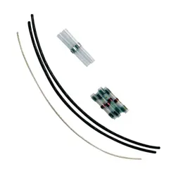
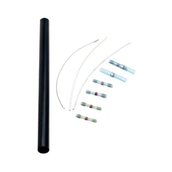
Materials and Tools Needed
Heating Cable Repair Kit: Manufacturer order number
81007142.
This heating cable repair kit contains components for making
a repair at one location. Certain components may not be used
depending on the method of repair selected.
Heat gun
• Must be able to heat to about 1000°F
Thermal wire strippers
• For stripping the heating wires
Scoring tool
• For cable with an outside jacket
Wire strippers
• For cutting and stripping 16-AWG wire
Small screwdriver
• To help separate heating wire from braid
• Paper clip or similar pointed tool may also be used
Digital multimeter
• Must measure up to 20,000 ohms
TDR (Time Domain Reflectometry) meter
• For diagnostic testing if additional damage is detected
Other Tools
Hammer and chisel
• For removal of tile and mortar if needed, and for creating a
“valley” in which to lay the splice
Hot glue gun with standard stick adhesive
• For adhering splice into the “valley” chiseled into floor
Scissors
To prevent the risk of personal injury and/or death,
make sure power is not applied to the product until
it is fully installed. All work must be done with the
power turned off.
WARNING
!
Watts Radiant highly recommends that only a qualified electrician
should make repairs to this product. In addition, please be aware
that local codes may require this control be installed or connected
by an electrician.
NOTICE
DO NOT USE this repair kit to splice different cables together.
The kit is only for making a repair within a cable.
DO NOT USE this repair kit to repair a cable within a shower
area or a mat that extends into a shower area.
WARNING
!

2
Part 2. Covering Removal
Step 2.1. Carefully remove the covering over the damaged
cable area.
Step 2.2. Remove enough covering to expose about 4" to 5" of
free wire on both sides of the damaged portion.
Part 3. Installing a Direct Splice
To install a jumper splice (please see Step 1.2), skip to Step 4.1.
Step 3.1. Cut out the damaged wire location, creating two ends
or leads. If the cable being repaired is not the jacketed
heating cable, skip to Step 3.6.
Step 3.2. Use the scoring tool to carefully score the jacket
about 2" from the end of each lead. Do this by placing the cable
lead into the V-notch of the tool and rotating the tool only one
or two revolutions around the cable. Do not place any additional
pressure on the tool head to cut deeper. Let the tool apply its
own spring-loaded pressure.
Step 3.3. Bend the cable to snap the jacket slug completely
loose at the score.
Step 3.4. Use the heat gun (set to HI temperature, about
1000°F) and move the gun back and forth under the jacket slug
for about 3 to 4 seconds until it starts to loosen and slightly
shrinks at the ends.
Step 3.5. Use a glove or other protective cloth to pull off the
loosened jacket slug. Do not touch the hot jacket slug with bare
fingers. The slug will be very hot and will burn!
Step 3.6. Loosen the braid by pushing back on the braid about
¼" and cause the ends of the heating wires to be exposed.
Step 3.7. Bend the cable back onto itself.
Step 3.8. Use the small screwdriver, paper clip, fingernail, or
similar blunt instrument to pry between the braid and make an
opening through which to pull the heating wires. Pull each wire
through the braid.
Step 3.9. Pull the braid tight to make it into a pigtail.
Step 3.10. Use the thermal wire strippers to carefully strip off
exactly ½" of the insulation from the heating wires. Count the
little heating elements to make sure none were cut off and
thereby cause a hot spot or possible failure. A fiber strand will
also be found among the heating elements. There is no need to
separate or remove this fiber strand.
Step 3.11. Use the digital multimeter and TDR at this repair
location before proceeding. Check for any additional damage
locations in the heating cable by “looking” in both directions. For
assistance in using these instruments, consult the instructions
that came with them or contact SunTouch technical support
888-4332-8932.
Step 3.12. Slide the solder tube over one of the heating wires.
Step 3.13. Pull the heating wires together to overlap the heating
elements of both leads. Lightly twist the elements together to better
join them. Slide the solder tube over the twisted elements, centering
the elements between the gray adhesive bands. If this is not done
correctly, the elements may pull out and cause the splice to fail.
Step 3.14. Use the heat gun (set to HI temperature, about
1000°F) to carefully heat the solder tube. First, heat directly
under the solder ring in the middle of the tube. IMPORTANT!
When the solder completely melts and flows into the wires,
continue heating for another 3 seconds. If the heat is removed
too soon, an incomplete solder connection will result, causing
connection failure later. When the solder is completely melted,
begin moving the heat gun back and forth under the rest of the
solder tube to shrink the tube and cause the adhesive bands at
the ends to melt and flow onto the wire insulation. After the tube
is completely shrunk and the adhesive bands are fully melted,
stop heating the tube. Additional heating will not help and may
cause either scorching of the tube or splice failure. Allow the
solder tube to cool for about 1 minute.
Step 3.15. REPEAT Steps 3.12 through 3.14 for the other
heating wire.
Step 3.16. Slide a ground solder tube over a ground braid lead.
Overlap the braid ends and twist them to help hold them together.
Slide the ground solder tube over the twisted braid ends,
centering them under the ring of solder.
Step 3.17. Heat the tube to shrink it completely and cause the
solder to flow into the twisted wires completely. When it cools,
the connection should be secure.
Step 3.18. The connection should now be complete and ready
to test. Go to Step 5.1 under “Testing the Repair.”
Part 4. Installing a Jumper Splice
Step 4.1. Cut out a 2"- to 3"-long section of the heating cable
around the damaged area, creating two ends or leads. If the
cable is not a jacketed heating cable, SKIP to Step 4.6.
Step 4.2. Use the scoring tool to carefully score the jacket
about 2" from the end of each lead. Do this by placing the cable
lead into the V-notch of the tool and rotating the tool only one
or two revolutions around the cable. Do not place any additional
pressure on the tool head to cut deeper. Let the tool apply its
own spring-loaded pressure.
Step 4.3. Bend the cable to snap the jacket slug completely
loose at the score.
Step 4.4. Use the heat gun (set to HI temperature, about
1000°F) and move the gun back and forth under the jacket slug
for about 3 to 4 seconds until it starts to loosen and slightly
shrinks at the ends.
Step 4.5. Use a glove or other protective cloth to pull off the
loosened jacket slug. Do not touch the hot jacket slug with bare
fingers. The slug will be very hot and will burn!
Step 4.6. Loosen the braid by pushing back on the braid about
¼", causing the ends of the heating wires to be exposed.
Step 4.7. Bend the cable back onto itself.
Step 4.8. Use the small screwdriver, paper clip, fingernail, or
similar instrument to pry between the braid and make an open-
ing through which to pull the heating wires. Pull each wire
through the braid.
Part 1. Getting Started
Step 1.1. Make sure the power is OFF!
Step 1.2. Two repair methods are shown in these guidelines.
Choose the method that is best for the installation.
Direct splice: This method is used when the damaged cable
has enough “play” to be cut and overlapped by about ¾ of an
inch. This also gives the best possible heating uniformity over
the splice versus using the jumper splice.
Jumper splice: This method is used when the damaged cable
does not have enough “play” to be cut and overlapped. This
also results in a splice section that will have very little heating
directly over the splice.
Step 1.3. Depending on the installation, the heating cable is
constructed in one of the two following ways:
Jacketed heating cable: This cable is comprised of two
insulated heating wires, covered by a metal braid, which in turn
is covered by an outer covering. Each heating wire consists of
one heating element that must be kept intact and undamaged.

3
Step 4.9. Pull the braid tight to make it into a pigtail.
Step 4.10. Use the thermal wire strippers to carefully strip off
exactly ½" of the insulation from the heating wires. Count the
little heating elements to make sure none were cut off and
thereby cause a hot spot or possible failure. A fiber strand will
also be found among the heating elements. There is no need to
separate or remove this fiber strand.
Step 4.11. Use the digital multimeter and TDR at this repair
location before proceeding. Check for any additional damage
locations in the heating cable by “looking” in both directions. For
assistance in using these instruments, consult the instructions
that came with them or contact SunTouch technical support.
Step 4.12. Cut the black jumper wires shorter, if necessary, so
that they overlap the stripped ends of the heating wires.
Step 4.13. Use the 16 AWG setting on the wire strippers to
strip off exactly ½" of the insulation from both ends of the black
jumper wires.
Step 4.14. Slide a solder tube over one of the heating wires on
one lead of the heating cable.
Step 4.15. Place the heating elements and black jumper wire
ends alongside each other. Lightly twist the elements together
to better join them. Slide the solder tube over the twisted
elements and over the edge of the insulation on the black jumper
wire. Make sure the twisted wires are fully inside the solder tube
and located between the adhesive bands at the ends of the
solder tube. If this is not done correctly, the elements may
pull out and cause the splice to fail.
Step 4.16. Use the heat gun (set to HI temperature, about
1000°F) to carefully heat the solder tube. First, heat directly
under the solder ring in the middle of the tube.
IMPORTANT! When the solder completely melts and flows
into the wires, continue heating for another 3 seconds.
If the heat is removed too soon, an incomplete solder
connection will result and cause connection failure later.
When the solder has completely melted, begin moving the heat
gun back and forth under the rest of the solder tube to shrink
the tube and cause the adhesive bands at the ends to melt and
flow onto the wire insulation. After the tube is completely shrunk
and the adhesive bands are fully melted, stop heating the tube.
Additional heating will not help and may cause either scorch-
ing of the tube or splice failure. Allow the solder tube to cool for
about 1 minute.
Step 4.17. REPEAT Steps 4.14 through 4.16 for the other
heating wire on the same lead.
Step 4.18. At the other end of the black jumper wires, slide a
solder tube over a heating wire. REPEAT Steps 4.14 through
4.17 to complete the jumper wire connections at this end.
Step 4.19. If necessary, cut the ground jumper wire shorter
so that it overlaps the ends of the ground braid lead wires by
about ½" to ¾".
Step 4.20. Overlap the ends of a ground braid lead and the
ground jumper wire by about ½" and twist them to help join
them together. Slide a ground solder tube over the twisted ends,
centering the ends under the solder ring. Heat the tube to shrink
it completely and cause the solder to flow into the wires completely.
When it cools, the connection should be secure.
Step 4.21. At the other end of the ground jumper wire, slide a
ground solder tube over the wire. REPEAT Step 4.20 to complete
this connection.
Step 4.22. The connection should now be complete and ready
to test. Go to Step 5.1 under “Testing the Repair.”
Part 5. Testing the Repair
After completing the splice connections and letting them cool,
test the repair as follows:
Step 5.1. Gently tug on each wire splice to make sure they do
not pull apart.
Step 5.2. Use a digital multimeter to measure the resistance of
the heating cable. This measurement should now fall within the
resistance range specified for this heating cable between the
heating wires, and no resistance should be measurable between
either heating wire and the green ground wire. If assistance is
needed with this step, follow the steps shown in the installation
manual for this cable, or call SunTouch technical support.
Step 5.3. Properly connect the repaired heating cable to the
power source through a GFCI, such as the SunTouch controller.
Operate the cable for a few days or at least for ten to fifteen
5-minute heating cycles. If the GFCI trips or the cable does not
heat, the cable will need to be checked for additional damage,
or else the repair may have failed.
Part 6. Final Steps
Make sure the splice is protected and lays flat on the floor
before installing floor coverings.
Step 6.1. If necessary, use a chisel to carefully carve a “valley”
under the splice.
Step 6.2. Cover with a similar material to protect against damage.

Warranty Disclaimer: This repair kit and these installation guidelines are provided by SunTouch to assist in repairing a SunTouch heating cable damaged at the job site. SunTouch does not, in any
way, warranty the repair or ensure proper function of the product following the repair. Only a qualified electrician should make repairs to the SunTouch heating cables. It is highly recommended that
an experienced tile installer remove the tile over the damage. For further assistance, please contact SunTouch.
SunTouch does not qualify electricians, tile installers, or SunTouch installers to perform diagnostics, tile removal, or cable repair. It is the responsibility of the installing party or homeowner to contact
a qualified person to follow these guidelines.
DO NOT USE this repair kit to splice different cables together. The kit is only for making a repair within a cable.
DO NOT USE this repair kit to repair a cable within a shower area or a mat that extends into a shower area.
IS-ST-ProMelt Repair Instructions 2333 81012896 © 2023 Watts
USA: T: (888) 432-8932 • F: (417) 831-4067 • SunTouch.com
Canada: T: (888) 208-8927 • F: (905) 481-2316
Latin America: T: (52) 55-4122-0138 • SunTouch.com