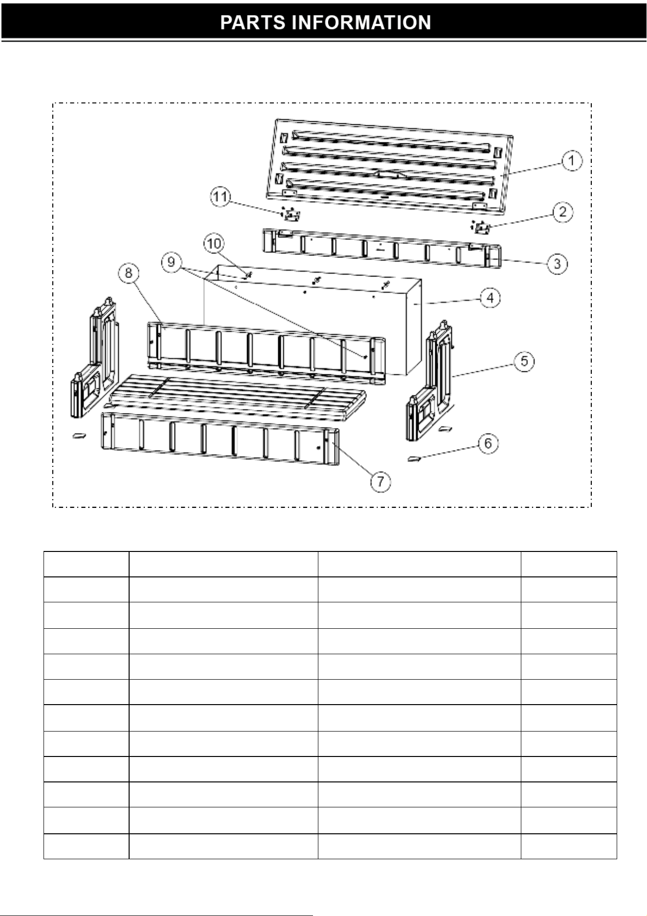
PART NO. ITEM NO. DESCRIPTION QTY
1 47151001 Treads 2
2 5760101000 Hinges 2
3 47151006 Small support 1
4 5760100000 Storage liner 1
5 47151003 Side Walls 2
6 5760102080 Foam Strip 1
7 47151005 Medium Support 1
8 47151004 Big Support 1
9 5212012000 ScrewsST4.8*20) 16
10 5244006000 Gasket 10
11 5212005000 Screws(ST3.9*11.6) 8
1

To
ols Needed
Rubber Mallet; Cordless Drill; Drill Bit
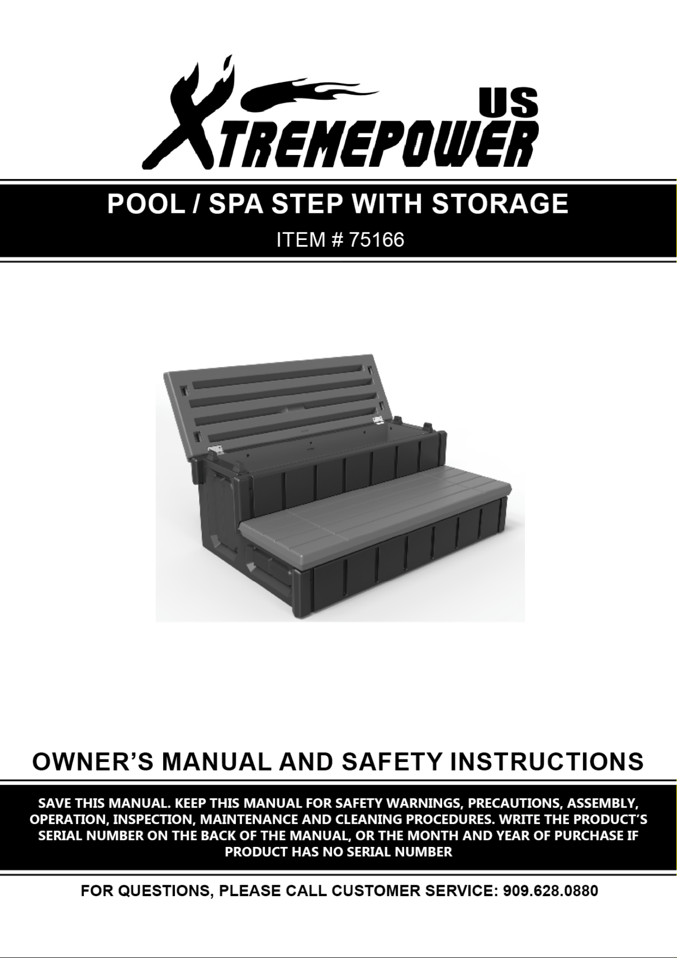
2. Warning and Caution
a) Check building codes/premitt
ing
Please consult your local Building Department before installation of your step and equipment in
order to reduce the risk of drowning, electrocution, falls, or other serious injury or death.
Equipment installation must comply with the codes of authority having jurisdiction and may
require permits(e,g.,building, plumbing, electrical, zoning, etc.). Be sure that barriers (fences,
gates, etc.) restricting spa access meet local codes.
b) Use for intended purpose only
Not intended for storing hazardous products(such as chemicals), which is not a secure location.
c) Check that you have all required parts
Check the contents of the carton with the parts list for the step. All parts and hardware are
required. DO NOT attempt to assemble or install the step if any parts missing.
d) Select an appropriate location
The Step must be located on a level solid base and in a location that will be in full view of
competent adult supervision when in use.
e) Follow all instruct
ions
- All instructions must be followed completely as the manual shown for stable corr
ect assembly
and installation.
- Use the hand tools and equipment appropriately according to the manufacturer’s
recommendations. CORDLESS DRILL ONLY. DO NOT use a corded drill in or around the pools
in order to lower the risks of electrocution.
f
) Lift safely
Have another person to help when lifting awkward or heavy loads.
g) Double check after installation
After well assembled and installationed, please double check the instructions and procedures
to make sure nothing has been overlooked before starting to use the step.
2
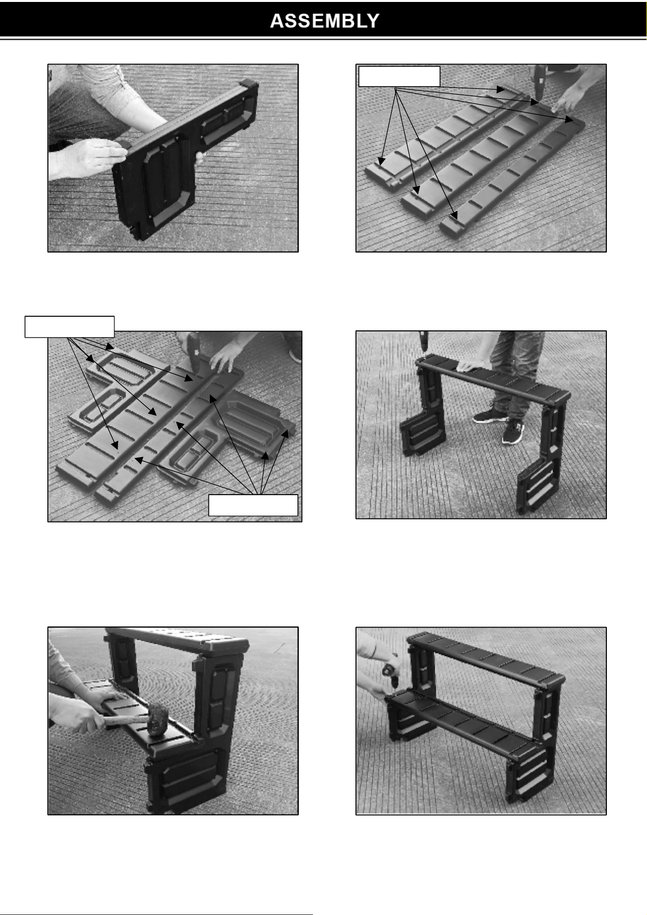
Drill
φ
5MM
Drill
φ
3.5MM
Drill
φ
3.5MM
STEP 1: Install 2 self-adhesive pads on each of
the sidewalls.
STEP 2: Pre-drill φ5mm pilot holes at the end of
the three supports. See image above.
STEP 3: Mark the position on both big and small
supports and the two sidewalls and pre-drill
φ3.5mm pilot holes.
STEP 4: Place the medium support over the two
locking tabs on the sidewalls. Tap down with the
mallet until seated on the locking tabs. Secure
the support at both ends using 2 x ST4.8*20
screws.
STEP 5: Place the large support over the two
locking tabs with the groove facing up. Tap down
with a rubber mallet until seated on the locking
tabs.
STEP 6: Use 2 x ST4.8*20 screws to seal both
ends of the support.
3
4
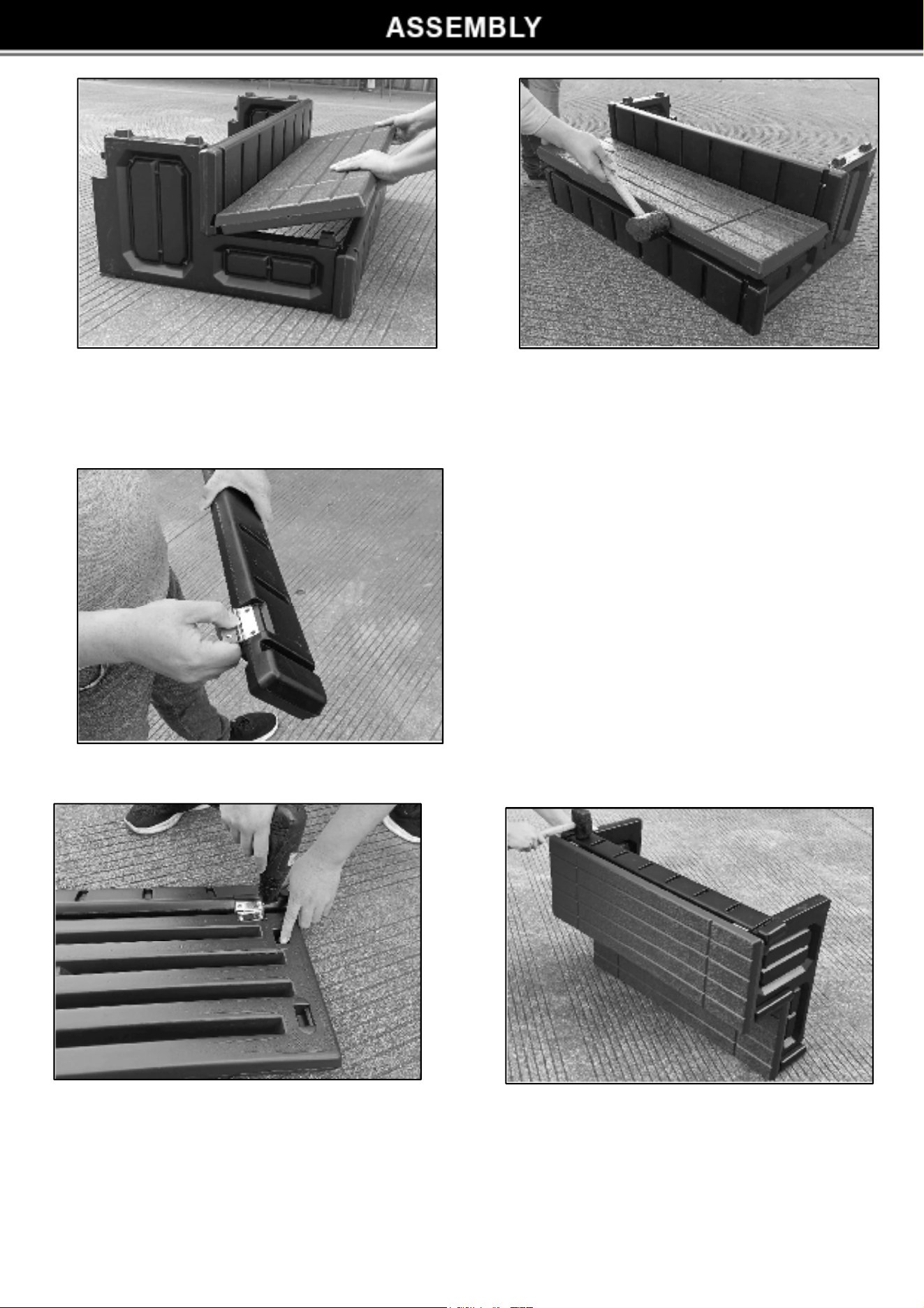
STEP 7: Place the tapered edge into the groove of the big support to install the bottom tread.
Apply pressure to force the tapered edge into the groove. Tap the front of the tread with the
rubber mallet while holding the tread in place. Tap down gently on the top of the tread until sealed
on the locking tabs.
STEP 8: Place the hinge (barrel side up) over
the mortised area of the small support. Attach 2 x
ST3.9*11.6 screws to fix up the hinge. No need to
drill the pilot holes. Please repeat to attach the
second hinge.
STEP 9: Place the tread on a flat surface
with the bottom facing up. Place the hinges
over the mortised area on the treads and fix
with 2 x ST3.9*11.6 screws in each hinge.
STEP 10: Place the small support on the
convex platform at the back of the sidewall,
then tap down with a rubber mallet until
seated onto the locking tabs.
Warning: To r
educe the risk of drowning,falls,paralysis,electrocution, or other serious injury or
death, use the step system properly.
• Use for
intended purpose only, no intend for chemical storage.
• No diving or jumping from steps, risk of paralysis or death.
• Only one person allowed on the step system at a time.
• Illuminate the steps when using the step system at night.
• Weight limited-300lbs., exceeding maximum weight may cause the step broken.
• Secure the spa when not in use. Please refer to local codes.(E.g. with a locked cover or secure
gate)
• Take care of the children at all times when they are in or around water to help prevent drowning.
• Be sure and safe. The manufacture is not responsible for improper assembly,installation and use.
Off state
Open state
5
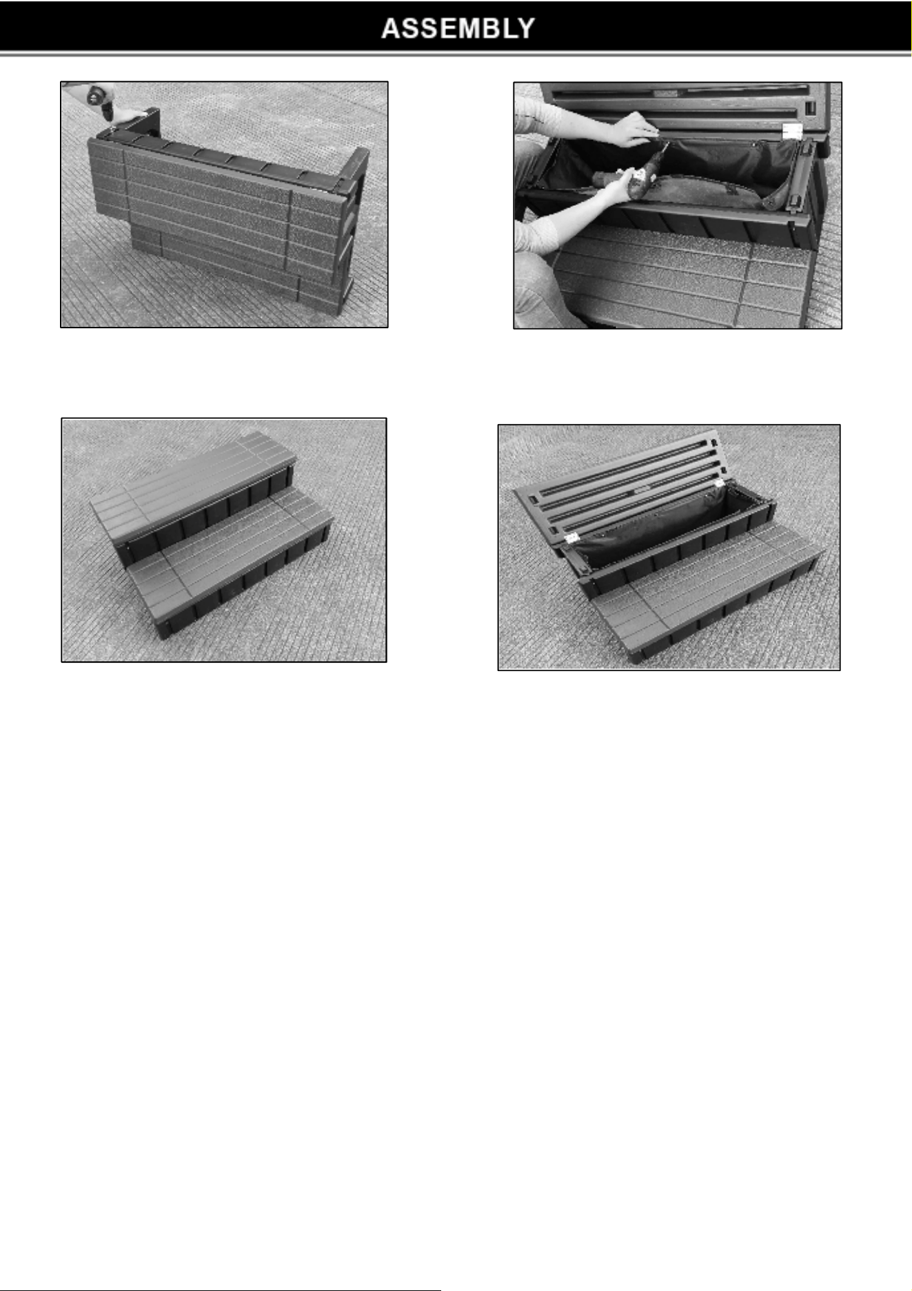
STEP 11: Secure both ends of the sidewall
with 2 x ST4.8*20 screws.
STEP 12: Open the above tread and place
the storage liner into the tread and fix with
screws and gaskets.
6