Installation Products
Owners manual/Bedienungsanleitung
© Dynaudio International GmbH, Installation Products Manual 0909, Item-No. 455915. All text and image copyrights reserved. Subject to change without notice.
Home Systems I Professional I Automotive I Multimedia

Dynaudio Installation Products / Installationsprodukte
Contents / Inhaltsverzeichnis
Contents
Introduction .......................................................................................1
Dear Music Lover,.........................................................................1
About this guide ................................................................................2
General safety instructions ..............................................................3
Unpacking ..........................................................................................4
Delivery contents ..........................................................................5
Installation recommendations .........................................................6
Positioning ....................................................................................7
Foam piece for sound damping and optimization .........................8
Re-painting.........................................................................................9
Installation .......................................................................................10
Checking the installation point ....................................................10
Installing IW 17, IP 17 and IP 24.................................................10
Installing IC 17 ............................................................................18
Running-in, Care & Maintenance ...................................................21
Running-in the loudspeakers ......................................................21
Power rating................................................................................21
Care & Maintenance ...................................................................22
Cleaning the loudspeakers .........................................................23
Warranty .....................................................................................23
Technical specifications.................................................................24
Brochures ........................................................................................25
Inhaltsverzeichnis
Einleitung ...........................................................................................1
Sehr geehrter Musikliebhaber,......................................................1
Zu dieser Anleitung...........................................................................2
Allgemeine Sicherheitshinweise......................................................3
Auspacken .........................................................................................4
Lieferumfang .................................................................................5
Einbauhinweise .................................................................................6
Positionierung ...............................................................................7
Dämmstoffe zur Klangoptimierung................................................8
Neu lackieren .....................................................................................9
Installation .......................................................................................10
Den Einbauort prüfen..................................................................10
IW 17, IP 17 und IP 24 installieren..............................................10
IC 17 installieren .........................................................................18
Inbetriebnahme, Pflegehinweise....................................................21
Einspielen der Lautsprecher .......................................................21
Belastbarkeit ...............................................................................21
Pflege..........................................................................................22
Die Lautsprecher reinigen...........................................................23
Garantie ......................................................................................23
Technische Daten............................................................................24
Broschüren ......................................................................................25
IP
_
IC
.
book
Seite
2
Freitag
,
15
.
August
2008
5:02
17

Dynaudio Installation Products / Installationsprodukte 1
Introduction / Einleitung
Introduction
Dear Music Lover,
Thank you for your decision to acquire a Dynaudio installation product.
The loudspeakers of the Installation Product series feature the
advanced Dynaudio technology, resulting in music reproduction at a
very high level, making many familiar recordings a new listening
experience altogether. This advanced technology results from many
years of intense research and development, the highest quality
standards in production, and Dynaudio’s enduring passion for musical
truth.
Dynaudio is one of very few companies who can realize such
loudspeaker concepts through its own in-house development and
production facilities. These facilities are so advanced and the quality
control is so strict that Dynaudio is likely the only specialty audio
company to have exceeded ISO 9000 and earned QS 9000
certification. Each loudspeaker is constructed by Dynaudio in Denmark
to these high standards of quality.
To realize the highest installation and sound quality, some areas should
be addressed, as will be explored on the following pages. By
considering the tips and suggestions, you will achieve the maximum
performance and enjoyment of the loudspeaker and its advanced
musical capabilities for a long time to come.
We wish you many years of enjoyment experiencing music,
Dynaudio
Einleitung
Sehr geehrter Musikliebhaber,
vielen Dank, dass Sie sich für ein Dynaudio Installationsprodukt
entschieden haben. Die Lautsprecher der Installationsprodukte Serie
beinhalten Dynaudio Technologie, die aus jeder Musikwiedergabe ein
beeindruckendes Erlebnis macht. Diese Technologie ist das Resultat
langjähriger Forschung und Entwicklung, höchster Qualitätsansprüche
und der für Dynaudio typischen Liebe zur wahrheitsgetreuen
Musikwiedergabe.
Dynaudio ist einer der wenigen Hersteller, der anspruchsvolle
Lautsprecherkonzepte nicht nur in eigener Entwicklung, sondern auch
in aufwändiger eigener Fertigung realisieren kann. Aufgrund dieser
Qualitätsorientierung ist Dynaudio nach der strengen, die ISO 9000
übertreffenden Qualitätsnorm QS 9000, zertifiziert. Jeder Lautsprecher
wird in Dänemark nach diesen höchsten Qualitätsanforderungen
gefertigt.
Um die bestmögliche Installation und Klangqualität zu erzielen, sollten
einige Anforderungen beachtet werden, die wir auf den folgenden
Seiten beschreiben. Sie werden so die Freude an Ihrem Installations-
Lautsprecher und an seinen musikalischen Fähigkeiten für viele Jahre
erhalten.
Wir wünschen Ihnen viel Spaß beim Musikhören,
Dynaudio
IP
_
IC
.
book
Seite
1
Freitag
,
15
.
August
2008
5:02
17
2 Dynaudio Installation Products / Installationsprodukte
About this guide / Zu dieser Anleitung
Zu dieser Anleitung
Verwendete Begriffe und Symbole
In dieser Anleitung werden folgende Begriffe und Symbole verwendet:
Das Ausrufezeichen in einem Dreieck macht den
Benutzer auf eine Gefahr aufmerksam, die zur
Beschädigung des Gerätes oder zu Verletzungen
führen kann.
VORSICHT Das Warnwort VORSICHT in Verbindung mit
einem Warnsymbol kennzeichnet eine Gefahr,
die zur Beschädigung des Gerätes und leichten
Verletzungen führen kann.
Hinweis Diese Textstellen geben Ihnen zusätzliche
Informationen, die zum Verständnis des
Lautsprechers und seiner Bedienung wichtig sind.
✓ Dieses Zeichen macht auf eine Voraussetzung
aufmerksam, die vor den darauffolgenden
Handlungen erfüllt sein muss.
X Stellen, die mit einem Pfeil gekennzeichnet sind,
fordern Sie auf, etwas zu tun. Lesen Sie bitte
sorgfältig die dort gegebenen Anleitungen.
1.
2.
3.
Mehrere Tätigkeiten, die nacheinander
ausgeführt werden müssen, sind entsprechend
nummeriert. Bitte befolgen Sie die angegebene
Reihenfolge.
About this guide
Used expressions and symbols
In this operating manual following expressions and symbols are used:
The exclamation point within an equilateral
triangle is intended to alert the user to the
presence of important operating and
maintenance (servicing) instructions in the
literature accompanying the product.
CAUTION Indicates (in combination with a safety sign) a
potentially hazardous situation which could
result in minor or moderate injury or damage to
equipment.
Note Additional information is provided, which is
important to fully understand the loudspeaker
and how to operate it.
✓ This sign indicates a step which must be taken
before the following actions.
X The arrow will identify steps to be performed.
Please follow the instructions carefully.
1.
2.
3.
Multiple steps that should be performed
consecutively are numbered.
Please follow these instructions carefully.
IP
_
IC
.
book
Seite
2
Freitag
,
15
.
August
2008
5:02
17
Dynaudio Installation Products / Installationsprodukte 3
General safety instructions / Allgemeine Sicherheitshinweise
General safety instructions
CAUTION
High sound levels
Listening to high sound pressure levels over a
longer period of time may harm your hearing.
X To avoid auditory effect do not listen to high
sound levels over a longer period of time.
CAUTION
Damage of structural fire protection
The cut out for an in-ceiling or in-wall speaker
installation could damage the fire protection
elements of a building. This may impact the fire
protection properties and violate fire protection
regulations.
X Observe and follow the local regulations for
structural fire protection.
X Contact an architect, the constructor or an
official authority for structural fire protection.
Allgemeine Sicherheitshinweise
VORSICHT
Hohe Schallpegel
Musikhören mit zu hoher Lautstärke über eine
längere Zeit kann das Gehör schädigen.
X Vermeiden Sie es, über eine längere Zeit mit
hoher Lautstärke Musik zu hören.
VORSICHT
Beschädigung des
Gebäudebrandschutzes
Das Ausschneiden von Einbauöffnungen für
Einbaulautsprecher beschädigt unter Umständen
die Brandschutzelemente des Gebäudes.
Hierdurch können die Feuerschutzeigenschaften
beeinträchtigt und gesetzliche Bestimmungen zum
Brandschutz verletzt werden.
X Beachten Sie die örtlichen Bestimmungen zum
Brandschutz an Gebäuden.
X Setzen Sie sich vor der Installation mit einem
Architekten, dem Bauherren oder einem
Brandschutzbeauftragten in Verbindung.
IP
_
IC
.
book
Seite
3
Freitag
,
15
.
August
2008
5:02
17

4 Dynaudio Installation Products / Installationsprodukte
Unpacking / Auspacken
Auspacken
1. Öffnen Sie den Karton und entnehmen Sie vorsichtig den Inhalt.
Wir empfehlen Ihnen, die Verpackung bis zum Abschluss der
Installation aufzubewahren.
2. Überprüfen Sie alle Bestandteile auf Vollständigkeit.
3. Entnehmen Sie den Lautsprecher aus der Kunststoffhülle.
Nur IP-Serie:
4. Entfernen Sie die Abdeckgitter vorsichtig vom Lautsprecher.
Ziehen Sie dazu gleichzeitig an den roten Folienstreifen.
5. Lösen Sie die Schrauben:
– IP 17: 6 Schrauben, Torx 20 Bit
– IP 24: 10 Schrauben, Torx 20 Bit
Bewahren Sie die Schrauben sorgfältig auf, da sie später bei der
Installation benötigt werden.
6. Nehmen Sie die Schallwand aus dem Aluminiumrahmen und
bewahren Sie beides in der Verpackung auf, bis Sie mit dem
Wandeinbau beginnen können.
X Siehe auch Kapitel „Installation“ auf Seite 10.
Unpacking
1. Fold the top carton flaps back and carefully remove the contents.
We suggest that you keep the entire packaging and all contents
until the installation is complete.
2. Check the contents; see next page.
3. Remove the speaker from the plastic bag.
IP series only:
4. Carefully remove the grille by lifting both ends of the red foil at the
same time.
5. Un-tighten the screws:
– IP 17: 6 screws, Torx 20 bit
– IP 24: 10 screws, Torx 20 bit
Place the screws into the accessory pack for later use.
6. Remove the baffle from the frame and, to avoid damage, keep
them in the supplied plastic bag (and preferably in the carton) away
from the work area until they are ready to be mounted.
X Also reference the chapter “Installation” on page 10.
IP
_
IC
.
book
Seite
4
Freitag
,
15
.
August
2008
5:02
17
Dynaudio Installation Products / Installationsprodukte 5
Unpacking / Auspacken
0
+
-
POSITIONING AND MOUNTING
TEMPLATE FOR
MODEL IC 17
1
2
4
3
5
6a
7
8a
8b
9101112
6b
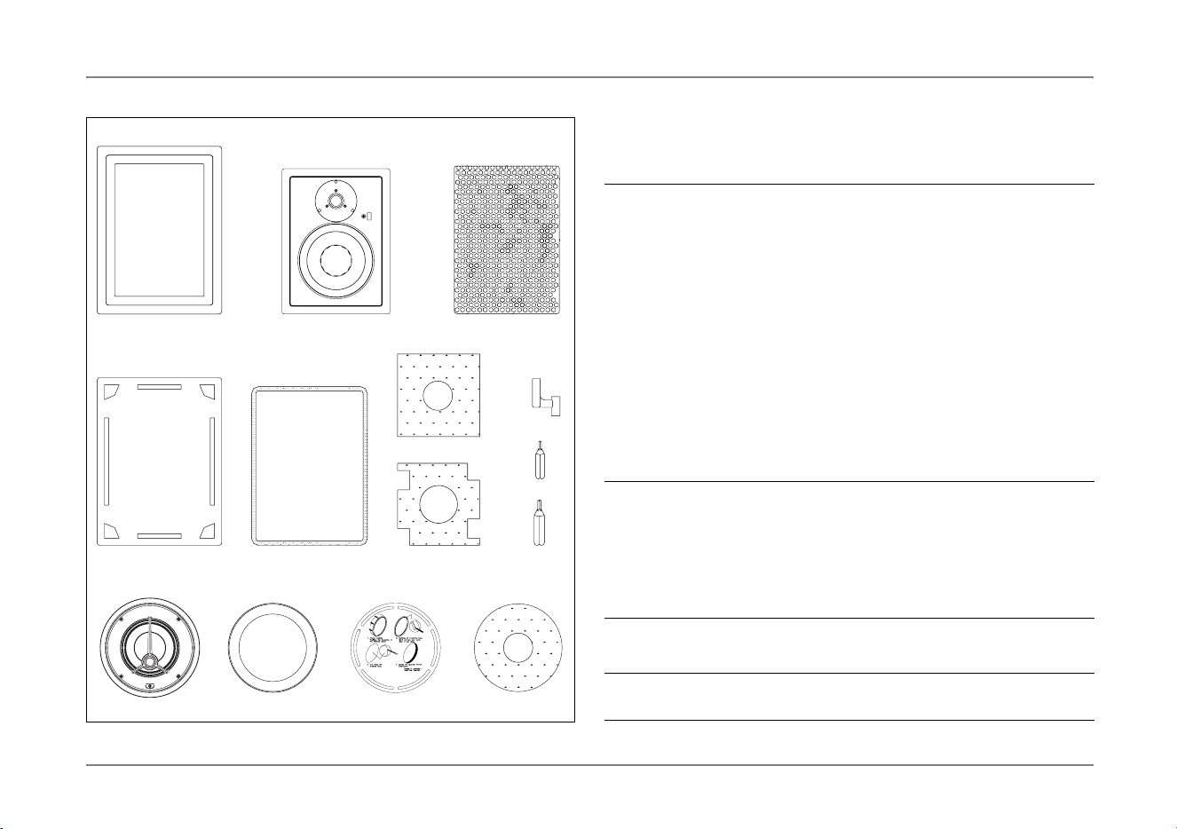
Delivery contents / Lieferumfang
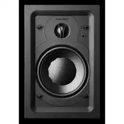
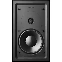
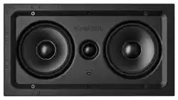
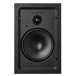
IW 17, IP 17, IP 24
IC 17
Accessories / Zubehör
1 Aluminium frame (including doglegs) (IP 17 and IP 24 only) /
Aluminiumrahmen (inkl. Rahmenklemmen) (nur IP 17 und IP 24)
2 Baffle with drivers and crossover /
Schallwand mit Chassis und Frequenzweiche
3 Grille / Abdeckgitter
4 Position template / Positionierungsschablone
5 Gasket (IP 17 and IP 24 only) / Dichtung (nur IP 17 und IP 24)
6a/b Foam piece / Schaumstoffmatte
6a: IP 17, IP 24; 6b: IW 17
7 Additional doglegs / zusätzliche Rahmenklemmen
8a/b 8a: Torx 15 Bit (IW 17); 8b: Torx 20 Bit (IP 17, IP 24)
8b Torx 2 0 Bit
9 Frame with drivers and crossover /
Rahmen mit Chassis und Frequenzweiche
10 Grille / Abdeckgitter
11 Position template / Positionierungsschablone
12 Foam piece / Schaumstoffmatte
1 pair white gloves / 1 Paar weiße Handschuhe
1 dust cloth / 1 Mikrofaser-Tuch
IP
_
IC
.
book
Seite
5
Freitag
,
15
.
August
2008
5:02
17

6 Dynaudio Installation Products / Installationsprodukte
Installation recommendations / Einbauhinweise
Einbauhinweise
Die Dynaudio IW/IP/IC-Modelle wurden so abgestimmt, dass sie in
verschieden großen Wand- bzw. Decken-Hohlräumen ihr
Klangpotenzial entfalten können.
Im Idealfall hat das Innenvolumen der Einbauöffnung folgende Werte:
Der Einbau in Hohlräume mit Luftschächten oder Rohren kann
aufgrund von Vibrationen die Klangqualität mindern.
Der Klang jedes Lautsprechers ist auch abhängig von der Einrichtung
im Raum. So entstehen bei großen Räumen mit wenigen
Einrichtungsgegenständen und vielen glatten Flächen ausgeprägte
Reflexionen und längere Nachhallzeiten, die das eigentliche
Musiksignal tendenziell hell und diffus klingen lassen. Ein stark
bedämpfter Raum mit vielen Einrichtungsgegenständen und vielen
weichen Flächen kann dagegen zu einem eher dunklen, leblosen
Klangbild führen.
Modell Innenvolumen
IW 17 > 15 Liter
IP 17 > 15 Liter
IP 24 > 30 Liter
IC 17 > 15 Liter
Installation recommendations
The Dynaudio IW/IP/IC models are designed to operate satisfactorily in
a wide range of cavity volumes.
Ideally these cavity volumes are:
Avoid installing the speakers in the same cavity as any ducts, as this
may result in excessive rattle.
The sound quality of any loudspeaker is influenced by the furniture, wall
materials and other objects in the listening room. For example, large
rooms without much furniture and many clean, hard wall surfaces can
give a bright and diffuse sound with diverse echoing frequencies. A
room with thick carpet, curtains and soft furniture surfaces will yield a
slightly warmer, darker and less lively sound.
Model Cavity volume
IW 17 > 15 liter (0.53 ft
3
)
IP 17 > 15 liter (0.53 ft
3
)
IP 24 > 30 liter (1.1 ft
3
)
IC 17 > 15 liter (0.53 ft
3
)
IP
_
IC
.
book
Seite
6
Freitag
,
15
.
August
2008
5:02
17

Dynaudio Installation Products / Installationsprodukte 7
Installation recommendations / Einbauhinweise
Positioning
Following explanations help you to find the right installation location:
• The distance between each loudspeaker and your listening position
should be the same.
• The closer the listening position is in relation to the loudspeakers,
the closer the speakers can be positioned to each other.
• If the speakers are positioned too close to each other, the stereo
image will not seem realistic; if that distance is too wide, the image
may leave an acoustic hole in the middle.
• If possible, keep the speakers at a distance greater than 20"
(0.5 m) away from any wall edges.Placement near the intersection
of a wall/ceiling, wall/floor or in a corner is not recommended, as it
may detract from the optimum sound quality.
• Due to the residual magnetic field from the drivers, it is advisable to
position the speakers at a minimum distance of 6" (0.15 m) from
CRT televisions to avoid any adverse effect on the picture.
Positionierung
Beachten Sie die folgenden Hinweise bei der Auswahl des Einbauorts:
• Der Abstand beider Lautsprecher zu Ihrem Hörplatz sollte gleich
groß sein.
• Je näher Sie sich bei den Lautsprechern befinden, desto geringer
kann auch der Abstand zwischen den Lautsprechern sein.
• Bei zu geringem Abstand zwischen den Lautsprechern entsteht
keine korrekte Stereo-Abbildung; bei zu großem Abstand ist die
Wiedergabe rechts-/linkslastig mit einem deutlich hörbaren Loch in
der Mitte.
• Aus klanglichen Gründen sollten Sie die Platzierung in Raumecken
sowie im Übergangsbereich zu der Decke oder dem Fußboden
vermeiden. Wir empfehlen, die Lautsprecher im Abstand von
mindestens 0,5 m zur nächsten Wandecke einzubauen.
• Um Bildstörungen durch magnetische Streufelder zu vermeiden,
sollten Sie einen Mindestabstand von 0,15 m zu einem
Fernsehgerät beachten.
IP
_
IC
.
book
Seite
7
Freitag
,
15
.
August
2008
5:02
17
8 Dynaudio Installation Products / Installationsprodukte
Installation recommendations / Einbauhinweise
Dämmstoffe zur Klangoptimierung
Die Steifigkeit der Wand bzw. Decke sowie die Dämpfung des
Hohlraums beeinflussen die Klangqualität eines gehäuselosen
Einbaulautsprechers.
X Beachten Sie nachfolgende Tipps, um die Klangqualität Ihrer
Lautsprecherinstallation zu verbessern:
• Die beigelegte Schaumstoffmatte bedämpft den Bereich direkt
hinter dem Lautsprecher. Grundsätzlich empfehlen wir, das
Wandvolumen mit Dämmstoffen wie Mineralwolle auszufüllen.
• Für eine kräftige Basswiedergabe sollte jedoch das Volumen im
Bereich von etwa 0,5 m um den Lautsprecher möglichst keine
Dämmstoffe enthalten. Für tiefere Bässe kann der dämmstofffreie
Bereich erweitert werden.
• Zusätzliche Verstrebungen und Verstärkungen im Hohlraum
stabilisieren die Einbauwand und können so die Klangqualität erhöhen.
• Um den Lautsprecher an unterschiedliche
Umgebungsbedingungen anpassen zu können, lässt sich der
Wiedergabepegel des Hochtöners verändern:
– IP-Serie: mit dem 3-stufigen Schalter rechts neben dem
Hochtöner um ±1,5 dB
– IW/IC-Serie: mit dem 3-stufigen Schalter im Frontrahmen
um ±2 dB
VORSICHT
Nicht zugelassene Dämmstoffe
Die Verwendung von nicht zugelassenen
Dämmstoffen kann Brandgefahr verursachen und
gesundheitsschädlich sein.
X
Beachten Sie beim Einsatz der Dämmstoffe
geltende Gesundheits- und Sicherheitsvorschriften.
Foam piece for sound damping and optimization
The sound quality of any installation loudspeaker system without a
cabinet enclosure is strongly influenced by the rigidity of the wall or
ceiling and the damping of the internal wall cavity.
X Note the following tips to improve the sound quality of your speaker
installation:
• A foam piece is supplied to damp the area behind the drive units.
We recommend the whole section of the wall cavity to be filled with
wadding, such as mineral wool used for insulation.
• To obtain a satisfactory bass response, keep the area of approx.
1.5 ft (0.5 m) around the speaker clear of wadding. If more bass is
required, remove more wadding around the speaker
• To further optimize the sound quality of the speaker, improve the
stiffness of the wall by adding bracing (inside the wall) around the
speaker.
• To adapt the loudspeaker to various environments the tweeter level
can be adjusted:
– IP series: with the 3-position switch placed on the right hand
side of the tweeter by ±1.5 dB
– IW/IC series: with the 3-position switch accessible via a hole in
the front plate by ±2 dB
CAUTION
Prohibited damping material
Using damping material that does not meet safety
regulations may cause fire and may be dangerous to
your health.
X Check that the materials you use meet the local
fire and building regulations.
IP
_
IC
.
book
Seite
8
Freitag
,
15
.
August
2008
5:02
17
Dynaudio Installation Products / Installationsprodukte 9
Re-painting / Neu lackieren
Re-painting
The frames and the grilles of the IW, IP and IC loudspeakers are
painted in a white semi-matte (RAL 9003) finish. Frames and grilles
may also be re-painted, and are ready to be refinished to match your
own interior décor scheme.
To paint the grille:
X Remove the grille and paint it in the desired color.
To paint the frame:
1. Remove the grille.
2. Protected drive units e.g. with a thin plastic foil.
3. Paint the aluminium frame in the desired color.
CAUTION
Improper painting
Do not paint the baffle (of the IP series
loudspeakers) and the drive units. Paint on these
parts may worsen the sound quality or even destroy
the product
X Protected the baffle and drive units e.g. with a thin
plastic foil when re-painting the frame or the
surrounding wall area.
X Avoid touching the drive units.
Neu lackieren
Die Rahmen und die Abdeckgitter der IW-, IP- und IC-
Lautsprecherserie sind in seidenmattem Weiß (RAL 9003) lackiert.
Rahmen und Gitter sind lackierbar und können damit problemlos an
eine individuelle Inneneinrichtung angepasst werden.
Um das Abdeckgitter zu lackieren:
X Nehmen Sie das Abdeckgitter ab und lackieren Sie es in der
gewünschten Farbe.
Um den Rahmen zu lackieren:
1. Nehmen Sie das Abdeckgitter ab.
2. Schützen Sie die Lautsprecher z. B. mit einer Folie vor
Farbspritzern.
3. Lackieren Sie den Aluminiumrahmen in der gewünschten Farbe.
VORSICHT
Unsachgemäßes Lackieren
Die Schallwand (der IP-Lautsprecherserie) und die
Lautsprecherchassis dürfen nicht lackiert werden.
Lack kann dort zu einer Verschlechterung der
Wiedergabequalität führen oder das Produkt sogar
zerstören.
X
Schützen Sie bei Malerarbeiten am
Aluminiumrahmen oder an der Wand die
Lautsprecher z. B. mit einer Folie.
X
Berühren Sie generell nicht die empfindlichen
Membranen der Hoch- und Tief-/Mitteltöner.
IP
_
IC
.
book
Seite
9
Freitag
,
15
.
August
2008
5:02
17
10 Dynaudio Installation Products / Installationsprodukte
Installation / Installation
Installation
Den Einbauort prüfen
IW 17, IP 17 und IP 24 installieren
Für die Montage der IP-Lautsprecher ist ein Metall-Einbaurahmen
erhältlich, der bei einer extra anzufertigenden Wand- bzw.
Deckenöffnung als Schablone und als mechanische
Rahmenverstärkung dient. Installateuren und Handwerkern erleichtert
dieser Rahmen, eine passende Wandöffnung vorzubereiten.
Besonders geeignet ist der Einbaurahmen z. B. für Zwischenwände,
Fertigwände oder Rigips-Wände, wie sie im Innenausbau verwendet
werden. Weitere Informationen erhalten Sie bei Ihrem Dynaudio
Fachhändler.
WARNUNG
Wasser, Gas, elektrischer Strom
Das Beschädigen von vorhandenen Installationen
kann zu schweren Verletzungen oder Tod führen.
X Stellen Sie sicher bevor Sie die Wand- oder
Deckenaussparungen freilegen, dass sich hier
keine anderen Installationen wie Rohre oder
Leitungen (Wasser, Gas, elektrischer Strom)
befinden. Suchen Sie mit einem Metalldetektor
den vorgesehenen Installationsort genau ab,
um Gefahren oder Schäden zu vermeiden.
X Grundsätzlich empfehlen wir Ihnen die
Beratung durch einen Fachmann.
Installation
Checking the installation point
Installing IW 17, IP 17 and IP 24
A pre-construction bracket is available to better facilitate new
construction installations of the Dynaudio IP loudspeakers, by working
both as a template as well as a structural support for the installation.
The bracket serves as a guide to the dry wall/sheet rock installer in
order to help them ensure that the loudspeaker cut-out openings are in
the desired location upon completion of the dry wall installation. The
stamped steel bracket is designed to fit between standard width studs
in order to accommodate the proper cutout for the loudspeaker
opening. For availability please check with your local Dynaudio dealer.
WARNING
Pipe work, air conditioning, power cabling
Damaging existing in-wall installations may cause
severe injury or death.
X
Before producing the wall or ceiling cut-out, be
sure that no conflict with other in-wall installations
will occur (pipe work, air conditioning, power
cabling, etc.). In existing (retrofit) construction
applications, use a stud-finding tool to map the
wall construction accurately, a pipe detector to
scan the proposed installation position and an
electrical field detector to help avoid any risk of
electrical damage or shock.
X Dynaudio strictly recommends asking a
professional for help.
IP
_
IC
.
book
Seite
10
Freitag
,
15
.
August
2008
5:02
17
Dynaudio Installation Products / Installationsprodukte 11
Installation / Installation
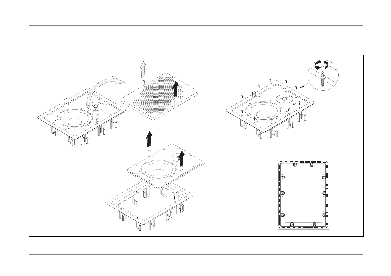
Installationsschritte (nur IP 17 und IP 24)
(Die Beschreibung der Schritte finden Sie auf der nächsten Seite.)
Installation steps (IP 17 and IP 24 only)
(For descriptions of the steps see next page.)
1.
3.
2.
4.
Figures show IP 24 / Abbildungen zeigen IP 24
IP
_
IC
.
book
Seite
11
Freitag
,
15
.
August
2008
5:02
17

12 Dynaudio Installation Products / Installationsprodukte
Installation / Installation
X Schneiden Sie die Wandöffung aus (für Abmessungen der
Wandöffnung siehe Seite 16 und Seite 17).
WARNUNG: Beachten und befolgen Sie die Warnhinweise zu
vorhandenen Installationen auf Seite 10!
IP 17 und IP 24 installieren
X Falls Sie die Lautsprecher bereits ausgepackt haben, fahren Sie mit
Schritt 4 fort, ansonsten beginnen Sie bei Schritt 1:
1. Entfernen Sie das Abdeckgitter vorsichtig. Ziehen Sie dazu an den
beiden roten Folienstreifen.
2. Lösen Sie die Schrauben (Torx 20 Bit): IP 17: 6, IP 24: 10
Bewahren Sie die Schrauben sorgfältig auf.
3. Entnehmen Sie die Schallwand vorsichtig an den roten
Folienstreifen und legen Sie sie zum Schutz in die Verpackung.
4. Beachten Sie die richtige Dichtungsposition auf der Rückseite.
5. Um den Rahmen in die Wand bzw. Deckenaussparung zu setzen:
a. Lösen Sie die Schrauben der Rahmenklemmen, bis sie frei
beweglich sind.
b. Beachten Sie, dass alle Rahmenklemmen nach innen gedreht
sind. Setzen Sie den Rahmen mit der Unterseite zuerst ein.
c. Je nach Wand- bzw. Deckenstärke gibt es zwei Möglichkeiten,
die Rahmenklemmen auszurichten:
– Wand- bzw. Deckenstärke 0 – 40 mm: siehe 5c. (I)
– Wand- bzw. Deckenstärke 36 – 65 mm: siehe 5c. (II)
6. Drehen Sie die Rahmenklemmen nach außen, so dass sie von
hinten gegen die Wand drücken. Ziehen Sie die Klemmen
vorsichtig fest. Achten Sie darauf, dass sich dabei die Klammern
nicht verdrehen.
X Produce the cut-out (for wall cut-out dimensions see page 16 and
page 17).
WARNING: Notice and follow the safety warnings about existing in-
wall installations on page 10!
Installing IP 17 and IP 24
X In case you have already unpacked your loudspeakers, continue
with step 4, otherwise start with step 1:
1. Carefully remove front grille by lifting up strips.
2. Un-tighten the screws (Torx 20 bit): IP 17: 6, IP 24: 10
Place the screws into the accessory pack for later use.
3. Carefully remove baffle by lifting up strips. Protect the baffle in the
original packing.
4. Make sure the gasket on the rear side is in correct position.
5. To put the frame inside the wall or ceiling cut-out:
a. Un-tighten the screws to bring the dogleg clamps from “locked”
position to “loose” position.
b. Make sure all doglegs are in “loose” position before frame is
positioned in the wall.
c. Depending on the wall or ceiling thickness, two different options
to turn the doglegs are available:
– Wall or ceiling thickness 0 – 40 mm (0 – 1.6"): see 5c. (I)
– Wall or ceiling thickness 36 – 65 mm (1.4 – 2.6"): see 5c. (II)
6. Turn the doglegs so they press against the wall by carefully
tightening the screws. Place your hand inside the cavity to control
and assure the doglegs movement.
IP
_
IC
.
book
Seite
12
Freitag
,
15
.
August
2008
5:02
17
Dynaudio Installation Products / Installationsprodukte 13
Installation / Installation
min.
min. 0 mm (0")
max. 40 mm (1.6")
min. 36 mm (1.4")
max. 65 mm (2.6")
max.
min.
max.
(I)
(II)
5a.
5b.
6.
5c.
IP 17 / IP 24
IW 17
IP
_
IC
.
book
Seite
13
Freitag
,
15
.
August
2008
5:02
17

14 Dynaudio Installation Products / Installationsprodukte
Installation / Installation
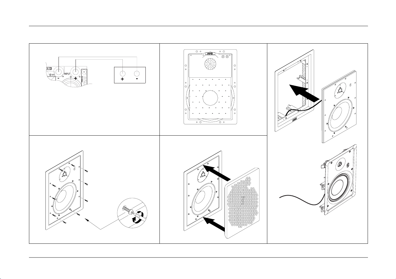
7. Achten Sie darauf, dass der Verstärker ausgeschaltet ist.
Verbinden Sie die Lautsprecheranschlüsse mit den Ausgängen des
Verstärkers.
8. Bringen Sie die Schaumstoffmatte auf der Rückseite hinter dem
Tief-/Mitteltöner an.
9. Setzen Sie die Schallwand mit der Oberseite zuerst in den
Aluminiumrahmen ein. Achten Sie darauf, dass Sie beim Einsetzen
die Kabel nicht eingeklemmt oder beschädigt werden.
10. Fixieren Sie die Lautsprechereinheit mit den Schrauben, die Sie
zu Beginn gelöst haben (siehe Schritt 2).
11. Setzen Sie das Abdeckgitter ein, indem Sie es zwischen Rahmen
und Schallwand vorsichtig andrücken. Drücken Sie nicht in der
Mitte des Abdeckgitters.
Herzlichen Glückwunsch. Die Installation ist abgeschlossen.
IW 17 installieren
Um den IW 17 zu installieren, führen Sie die zuvor beschriebenen
Schritte in folgender Reihenfolge durch:
X Schritt 7
X Schritt 8
X Schritt 5
X Schritt 6
X Schritt 11
Herzlichen Glückwunsch. Die Installation ist abgeschlossen.
7. Make sure that the amplifier power is switched off.
Connect the speaker terminal to the amplifier.
8. Put the foam on the rear side of the woofer in its correct position.
9. Position the baffle with top first. Make sure not to jam or damage
the speaker wire.
10. To lock the speaker unit into position tighten the screws, which you
have unscrewed at the beginning (see step 2).
11. Insert the grille by pressing it carefully into the gap between the
frame and baffle. Do not press in the middle of the grille.
Congratulations. Installation is complete.
Installing IW 17
To install the IW 17, perform the previously described steps in following
order:
X Step 7
X Step 8
X Step 5
X Step 6
X Step 11
Congratulations. Installation is complete.
IP
_
IC
.
book
Seite
14
Freitag
,
15
.
August
2008
5:02
17
Dynaudio Installation Products / Installationsprodukte 15
Installation / Installation
9.7. 8.
11.10.
Crossover /
Frequenzweiche
Amplifier /
Verstärker
Figures show IP 24 / Abbildungen zeigen IP 24
IP 17 / IP 24
IW 17
IP
_
IC
.
book
Seite
15
Freitag
,
15
.
August
2008
5:02
17
16 Dynaudio Installation Products / Installationsprodukte
Installation / Installation
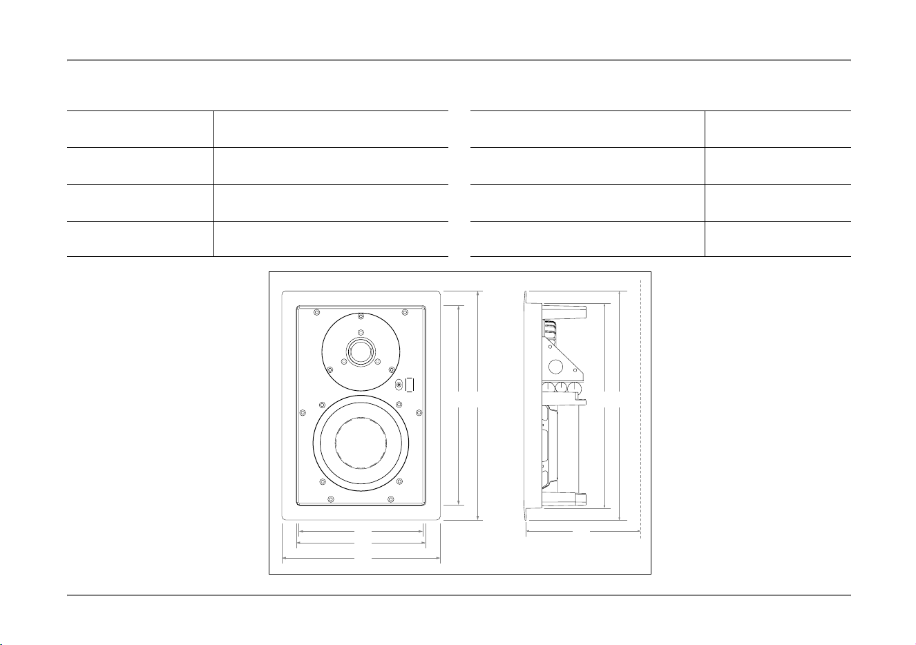
Dimensions IW 17 / IP 17
Gehäuse (IW 17) / Rahmen (IP 17) a
b
Höhe:
Breite:
289/325 mm
195/225 mm
Wandaussparung (IW 17/IP 17) c
d
Höhe:
Breite:
269,5/295 mm
175,5/194 mm
Abdeckgitter (IW 17/IP 17) e
f
Höhe:
Breite:
260/285 mm
163,5/185 mm
Mindesteinbautiefe
(IW 17/IP 17)
g Tiefe: 92/92 mm
Dimensions IW 17 / IP 17
Housing (IW 17) /
Mounting frame (IP 17)
a
b
Height:
Width:
289/325 mm
195/225 mm
(11.38/12.80")
(7.68/8.86")
Cut out (IW 17/IP 17) c
d
Height:
Width
269,5/295 mm
175,5/194 mm
(10.61/11.61")
(6.91/7.64")
Grille (IW 17/IP 17) e
f
Height:
Width:
260/285 mm
163,5/185 mm
(10.24/11.22")
(6.44/7.28")
Minimum depth required
(IW 17/IP 17)
g Depth: 92/92 mm (3.62/3.62")
ea
f
d
b
-
0
+
g
ca
Figure shows IP 17 / Abbildung zeigt IP17
IP
_
IC
.
book
Seite
16
Freitag
,
15
.
August
2008
5:02
17
Dynaudio Installation Products / Installationsprodukte 17
Installation / Installation
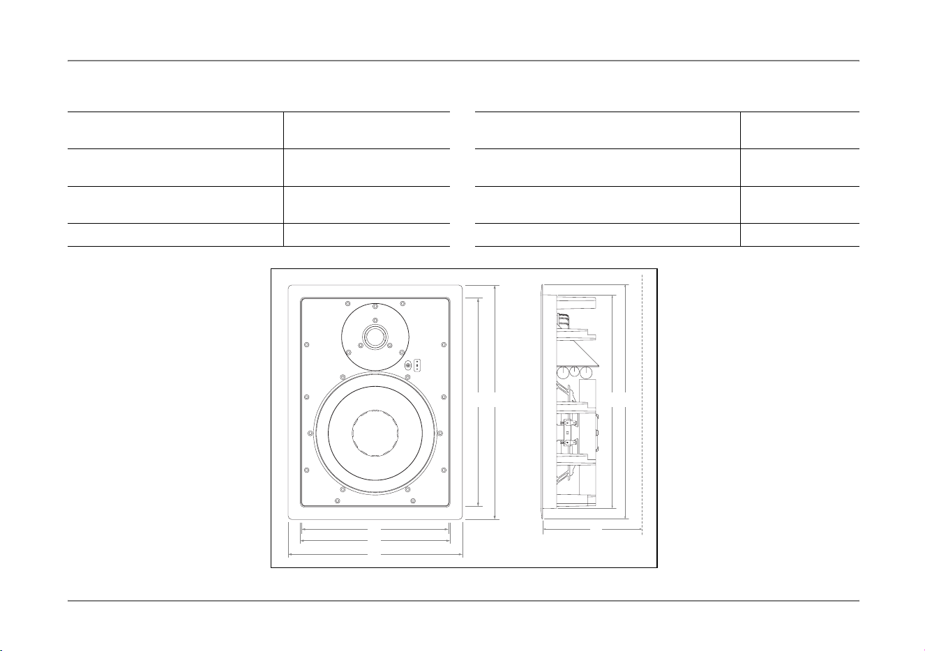
Abmessungen IP 24
Aluminiumrahmen a
b
Höhe:
Breite:
385 mm
286 mm
Wandaussparung c
d
Höhe:
Breite:
351 mm
252 mm
Abdeckgitter e
f
Höhe:
Breite:
343 mm
244 mm
Mindesteinbautiefe g Tiefe: 92 mm
Dimensions IP 24
Aluminium mounting frame a
b
Height:
Width:
385 mm
286 mm
(15.15")
(11.25")
Cut out c
d
Height:
Width:
351 mm
252 mm
(13.82")
(9.92")
Grille e
f
Height:
Width:
343 mm
244 mm
(13.50")
(9.60")
Minimum depth required g Depth: 92 mm (3.62")
ae
f
d
b
ac
g
IP
_
IC
.
book
Seite
17
Freitag
,
15
.
August
2008
5:02
17

18 Dynaudio Installation Products / Installationsprodukte
Installation / Installation
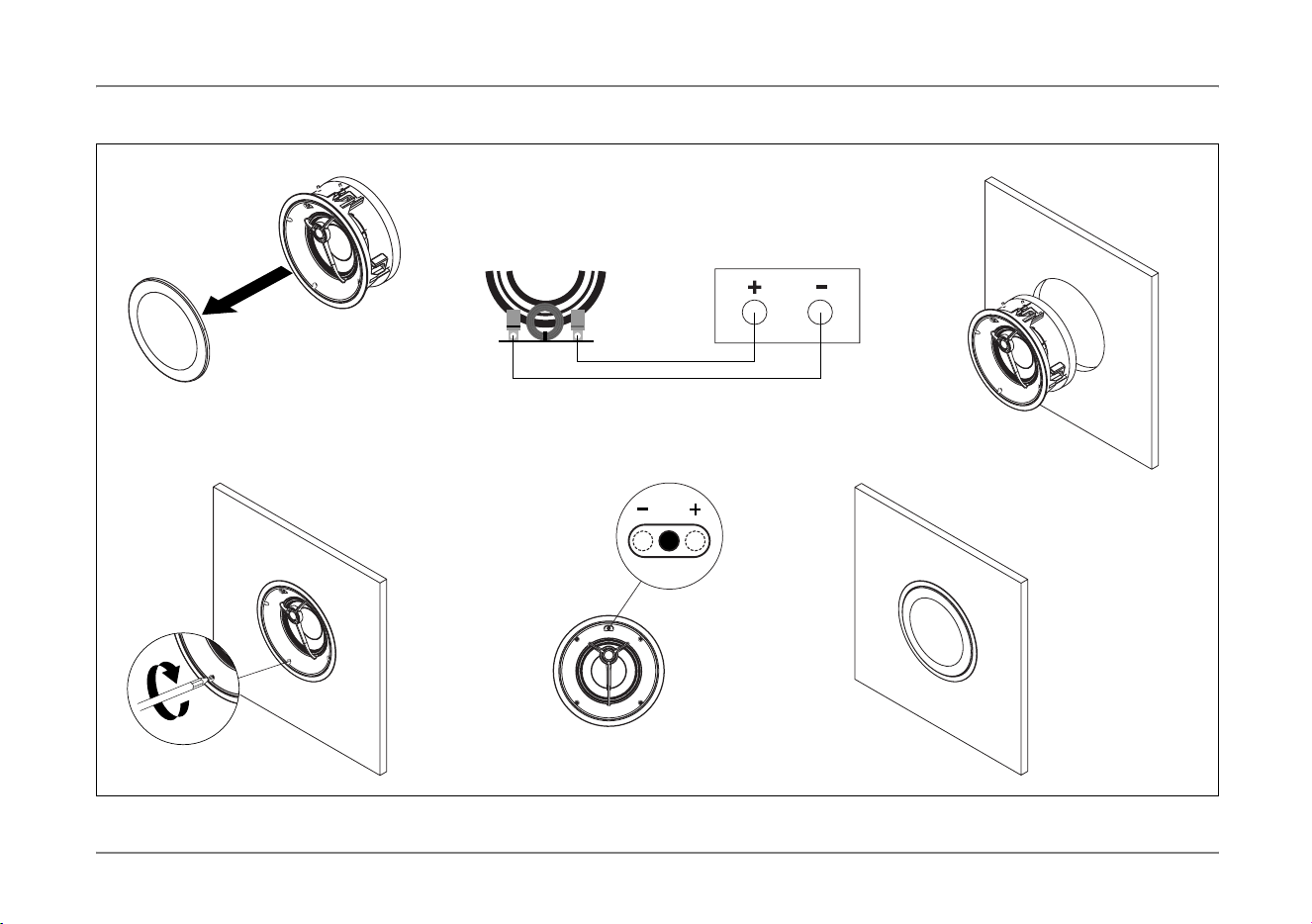
IC 17 installieren
Die Montage des IC 17 Deckenlautsprechers ist sehr einfach. Es werden
keine zusätzlichen Montagehilfen benötigt.
Installationsschritte
X Für Abmessungen der Wandöffnung siehe Seite 20.
1. Nehmen Sie das Abdeckgitter ab (das Abdeckgitter ist nur
aufgesteckt).
2. Verbinden Sie die vom Verstärker kommenden Lautsprecherkabel
mit den Anschlüssen an der Frequenzweiche des Lautsprechers:
a. Verbinden Sie den Plus-Leiter mit der rot markierten Plus-
Klemme (+). In der Regel hat der Plus-Leiter eine zusätzliche
Markierung.
b. Verbinden Sie den Minus-Leiter mit der schwarz markierten
Minus-Klemme (–).
3. Setzen Sie den Lautsprecher in die Deckenöffnung ein.
4. Ziehen Sie die vier Schrauben kreuzweise fest, bis der
Lautsprecher stabil in der Öffnung sitzt.
Den Lautsprecher anpassen
Über einen von vorne zugängigen Pegelsteller kann der Hochtöner in drei
Stufen eingestellt werden. Hierdurch lässt sich
der
IC 17
Deckenlautsprecher an unterschiedliche Wiedergabesituationen
anpassen.
✓
Das Abdeckgitter ist abgenommen.
5. Stellen Sie den Pegelsteller auf die gewünschte Stufe.
6. Stecken Sie das Abdeckgitter wieder auf.
Installing IC 17
Installing the IC 17 ceiling loudspeaker is very easy. No additional
installation aids are needed.
Installation steps
X For wall cut out dimensions see page 20.
1. Remove the grille from the loudspeaker (the grille is simply clipped
into place).
2. Connect the loudspeaker cables coming from the amplifier to the
terminals of the frequency crossover at the loudspeaker:
a. Connect the positive lead to the red marked positive
terminal (+). The positive lead usually has an additional
identification label.
b. Connect the negative lead to the black marked negative
terminal (–).
3. Mount the loudspeaker into the ceiling cut out.
4. Tighten the four screws crosswise until the loudspeakers is
properly secured.
Setting up the loudspeaker
The tweeter sound level can be adjusted in three steps by means of a
level switch accessible from the speaker front. This allows you to adapt
the IC 17 ceiling loudspeaker to various acoustic environments.
✓
The grille is un-mounted.
5. Set the level switch at the desired level.
6. Clip the grille onto the speaker frame.
IP
_
IC
.
book
Seite
18
Freitag
,
15
.
August
2008
5:02
17
Dynaudio Installation Products / Installationsprodukte 19
Installation / Installation
4x
0
+
_
1. 2. 3.
4. 5. 6.
Crossover /
Frequenzweiche
Amplifier /
Verstärker
IP
_
IC
.
book
Seite
19
Freitag
,
15
.
August
2008
5:02
17
20 Dynaudio Installation Products / Installationsprodukte
Installation / Installation
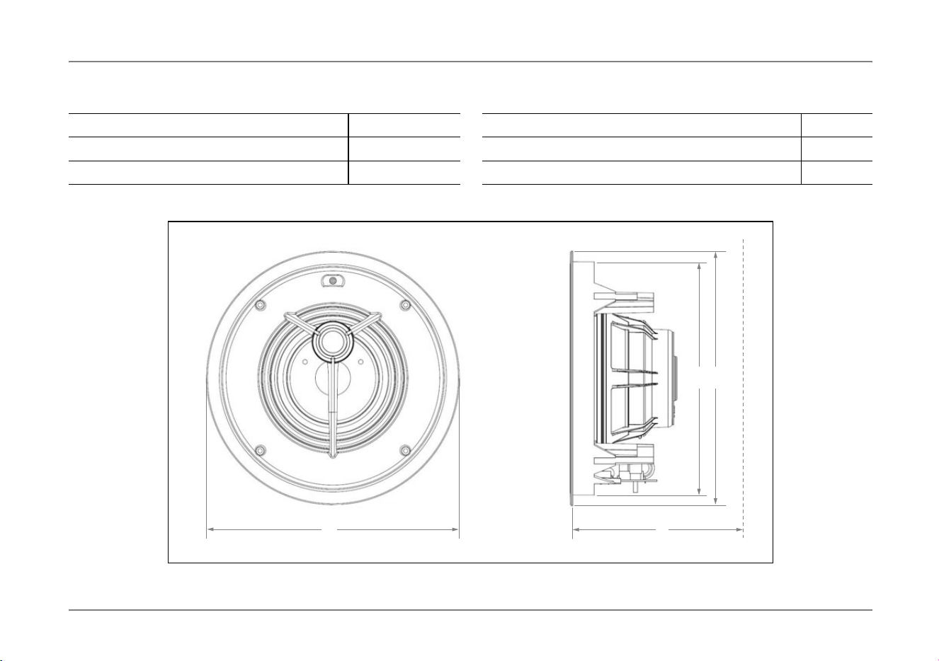
Abmessungen IC 17
Außendurchmesser a 236 mm
Durchmesser der Deckenaussparung b 218 mm
Mindesteinbautiefe c 109 mm
Dimensions IC 17
Dimensions (Ø) a 236 mm (9.3")
Cut out (Ø) b 218 mm (8.6")
Minimum depth required c 109 mm (4.3")
a
b a
c
IP
_
IC
.
book
Seite
20
Freitag
,
15
.
August
2008
5:02
17

Dynaudio Installation Products / Installationsprodukte 21
Running-in, Care & Maintenance / Inbetriebnahme, Pflegehinweise
Running-in, Care & Maintenance
Running-in the loudspeakers
The moving parts of a newly manufactured loudspeaker have been
acoustically checked after production, but nevertheless are not as
flexible as they need to be for optimum results to be realized. The
higher the quality of any driver system, the more demanding the
loudspeaker will be regarding time for running-in the system.
A newly unpacked Dynaudio loudspeaker therefore requires several
weeks running/playing to reach its optimum performance capability.
After that period, a couple of minutes before every listening session will
be helpful to “warm up” the loudspeakers.
Power rating
Due to the construction and the driver technology the loudspeakers can
be driven with very high power levels. With a high quality amplifier,
delivering undistorted signals, the speaker can achieve high volumes
without any compromises in sound quality.
Also, as the loudspeakers have a relatively high sensitivity, even high
quality amps with a low power rating can drive the loudspeaker to yield
excellent results.
Attention must be given to amplifiers with very low power and
adjustable tone controls or switches. These types may soon overreach
their own performance limits and may send distorted output signals to
the speakers, compromising even high quality technology. Any
damage caused under such circumstances is not covered by the
Dynaudio warranty and is easily avoided in the first place by consulting
your Dynaudio dealer for advice regarding the choice of amplifier.
Inbetriebnahme, Pflegehinweise
Einspielen der Lautsprecher
Die beweglichen Teile eines Lautsprechers haben im Neuzustand trotz
vorhergehender akustischer Qualitätskontrollen noch nicht ihre volle
Bewegungsfreiheit und damit ihr mögliches Klangpotential erreicht. Je
besser die Qualität der Lautsprecherchassis, desto anspruchsvoller ist
ein Lautsprecher bei der Einspielzeit.
Ein neu gefertigter Dynaudio Lautsprecher benötigt daher – je nach
Pegel und Nutzungsdauer – einige Wochen, um seine optimale
Klangqualität zu erreichen. Danach genügen jeweils einige Minuten,
um auf höchstem Niveau spielen zu können.
Belastbarkeit
Die Belastbarkeit der Lautsprecher ist durch die Konstruktion und
Materialwahl der Chassis besonders hoch. Mit einem leistungsfähigen,
unverzerrt arbeitenden Verstärker können die Lautsprecher nach einer
gewissen Einspielzeit mit sehr hohem Pegel ohne Beeinträchtigung der
Klangqualität spielen.
Folgender Punkt muss jedoch beachtet werden: Verstärker mit sehr
niedriger Leistung sowie Verstärker mit regelbaren Klangeinstellungen
können bei großen Lautstärken in den hohen Frequenzen verzerrte
Signale produzieren. Dieses so genannte „Clipping“ kann selbst die
beste Lautsprechertechnik dauerhaft beschädigen.
Derartige Beschädigungen werden nicht durch die Garantieleistung
abgedeckt und sollten daher durch vorherige Beratung mit Ihrem
Dynaudio Fachhändler vermieden werden.
IP
_
IC
.
book
Seite
21
Freitag
,
15
.
August
2008
5:02
17
22 Dynaudio Installation Products / Installationsprodukte
Running-in, Care & Maintenance / Inbetriebnahme, Pflegehinweise
Pflege
Dynaudio Lautsprecher bedürfen keiner besonderen Pflege, die über
die Anforderungen anderer hochwertiger Geräte hinaus geht.
VORSICHT
Verzerrte Verstärkersignale
Verzerrte Signale von zu schwachen, defekten
oder überlasteten Verstärkern können den
Lautsprecher beschädigen.
X Verwenden Sie nur qualitativ hochwertige
Verstärker und betreiben Sie Lautsprecher und
Verstärker nur innerhalb der angegeben
Leistungsgrenzen.
VORSICHT
Aggressive Reinigungsmittel
Universalreiniger, aggressive Reinigungsmittel
oder spezielle Möbelpolituren können die
Gehäuseoberfläche oder andere
Lautsprecherteile beschädigen.
X Verwenden Sie lediglich ein weiches und leicht
feuchtes Tuch zum Reinigen der Lautsprecher.
Care & Maintenance
Dynaudio loudspeakers require no special treatment apart from the
kind of careful handling you would normally apply to any high tech
product in your home.
CAUTION
Distorted output signals
Distorted output signals from too weak, defective or
overloaded amplifiers may damage the
loudspeakers.
X Use high quality amplifiers only and run
loudspeakers and amplifiers within specified
power ratings.
CAUTION
Aggressive cleaning fluids
All-in-one cleaning materials, aggressive cleaning
fluids or special furniture polishes may damage the
cabinet surface or other speaker parts.
X Use a soft dry or slightly damp cloth when
cleaning the cabinet and other plain parts.
IP
_
IC
.
book
Seite
22
Freitag
,
15
.
August
2008
5:02
17

Dynaudio Installation Products / Installationsprodukte 23
Running-in, Care & Maintenance / Inbetriebnahme, Pflegehinweise
Cleaning the loudspeakers
X Switch off all components of your system when cleaning any of
these components.
X Clean the grille with a soft dry or slightly damp cloth only.
All materials used by Dynaudio are integrated with exceptional care. By
taking care of your loudspeakers, you will preserve the finish and build
quality for a very long time.
Warranty
Dynaudio provides a transferable five-year limited manufacturer’s
warranty.
This warranty only covers faults or defects in material and production.
Damage caused as a result of abuse, misuse or defective electronics is
not covered by the warranty.
All warranty claims must be accompanied by a copy of the original
purchase invoice and warranties are only valid in the country or market
of original origin or distribution. Should warranty service be required, it
must be arranged for in the country of purchase by an authorized
Dynaudio dealer.
Die Lautsprecher reinigen
X Schalten Sie zur Sicherheit bei jedem Reinigen Ihrer Anlage alle
Geräte aus.
X Verwenden Sie ein fusselfreies, leicht feuchtes Tuch zur Reinigung
des Abdeckgitters.
Alle verwendeten Materialien wurden von Dynaudio mit höchster
Sorgfalt verarbeitet. Bei richtiger Pflege werden Sie diese Verarbeitung
für sehr lange Zeit erhalten.
Garantie
Dynaudio gewährt auf Lautsprecher eine Garantie von 5 Jahren.
Bitte beachten Sie regionale Sondervereinbarungen, um eine über die
gesetzliche Gewährleistungsfrist erweiterte Dynaudio Garantie von 5
Jahren zu erhalten.
Diese Garantie erstreckt sich ausschließlich auf Material- und
Fertigungsmängel. Schäden, die durch unsachgemäßen Betrieb oder
defekte Verstärker entstanden sind, werden von der Garantie nicht
abgedeckt.
Als Nachweis für den Garantieanspruch gilt der Kaufbeleg. Die
Abwicklung von Reklamationen erfolgt in der Regel über Ihren
autorisierten Dynaudio Fachhändler.
IP
_
IC
.
book
Seite
23
Freitag
,
15
.
August
2008
5:02
17
24 Dynaudio Installation Products / Installationsprodukte
Technical specifications / Technische Daten
Technische DatenTechnical specifications
IW 17 IP 17 IP 24 IC 17
Principle /
Konstruktionsprinzip
2 way /
2-Wege
2 way /
2-Wege
2 way /
2-Wege
2 way axial /
2-Wege axial
Mid/woofer /
Tief-/Mitteltöner
165 mm (6.5")
cone / Konus
165 mm (6.5")
cone / Konus
240 mm (10")
cone / Konus
165 mm (6.5")
cone / Konus
Tweeter /
Hochtöner
21 mm (3/4")
dome / Kalotte
28 mm (1.1")
dome / Kalotte
28 mm (1.1")
dome / Kalotte
21 mm (3/4")
dome / Kalotte
Sound level adjust (Tweeter) /
Pegelanpassung (Hochtöner)
±2 dB ±1.5 dB ±1.5 dB ±2 dB
Sensitivity (2.83 V/1 m) /
Empfindlichkeit (2,83 V/1 m)
88 dB 88 dB 90 dB 88 dB
IEC Long Term Power Handling /
Belastbarkeit (Langzeit)
100 W 150 W 150 W 100 W
Impedance (nominal) /
Impedanz (nominal)
4 – 6 Ohm,
linearized / linearisiert
8 Ohm,
linearized / linearisiert
4 Ohm,
linearized / linearisiert
4 – 6 Ohm,
linearized / linearisiert
Frequency Response (±3 dB) /
Frequenzbereich (
±
3 dB)
45 Hz – 25 kHz 45 Hz – 23 kHz 40 Hz – 23 kHz 45 Hz – 25 kHz
Dimensions (W x H) /
Abmessungen (B x H)
195 x 289 mm
(7.68 x 11.38")
225 x 325 mm
(8.86 x 12.80")
286 x 385 mm
(11.25 x 15.15")
Ø 236 mm
(Ø 9.3")
Weight / Gewicht 1.7 kg (3.74 lbs) 3.0 kg (6.61 lbs) 3.5 kg (7.71 lbs) 1.5 kg (3.31 lbs)
IP
_
IC
.
book
Seite
24
Freitag
,
15
.
August
2008
5:02
17
Dynaudio Installation Products / Installationsprodukte 25
Brochures / Broschüren
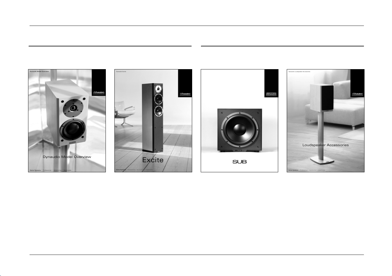
Brochures Broschüren
Model Overview /
Modellübersicht
Excite Loudspeakers /
Excite Lautsprecher
Subwoofer Line /
Subwoofer-Serie
Loudspeaker Accessories /
Lautsprecherzubehör
IP
_
IC
.
book
Seite
25
Freitag
,
15
.
August
2008
5:02
17

© Dynaudio International GmbH, Installation Products Manual 0909, Item-No. 455915. All text and image copyrights reserved. Subject to change without notice.
Dynaudio A/S, 8660 Skanderborg, Denmark
Sales & Marketing: Dynaudio International GmbH, Ohepark 2, 21224 Rosengarten, Germany, Phone: +49 4108 - 41 80 - 0
www.dynaudio.com