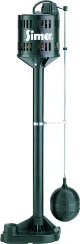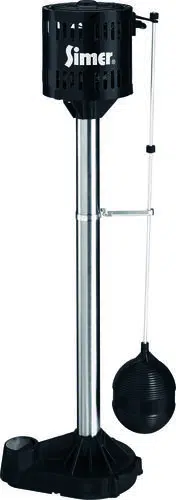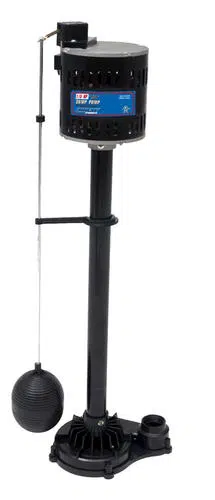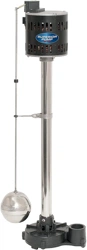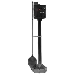
Submersible Pump
SKU: 76081
Owner's
Manual
E248578
QSB-2JH-SS025
USC
LISTED
26XZ
76081


TABLE OF CONTENTS
ITEM DIAGRAM 2
SPECIFICATIONS AND SAFETY 3
FLOAT SWITCH INSTALLATION 5
OPERATION 7
COMPONENT DIAGRAM 8
TROUBLESHOOTING 9
PARTS LIST 10
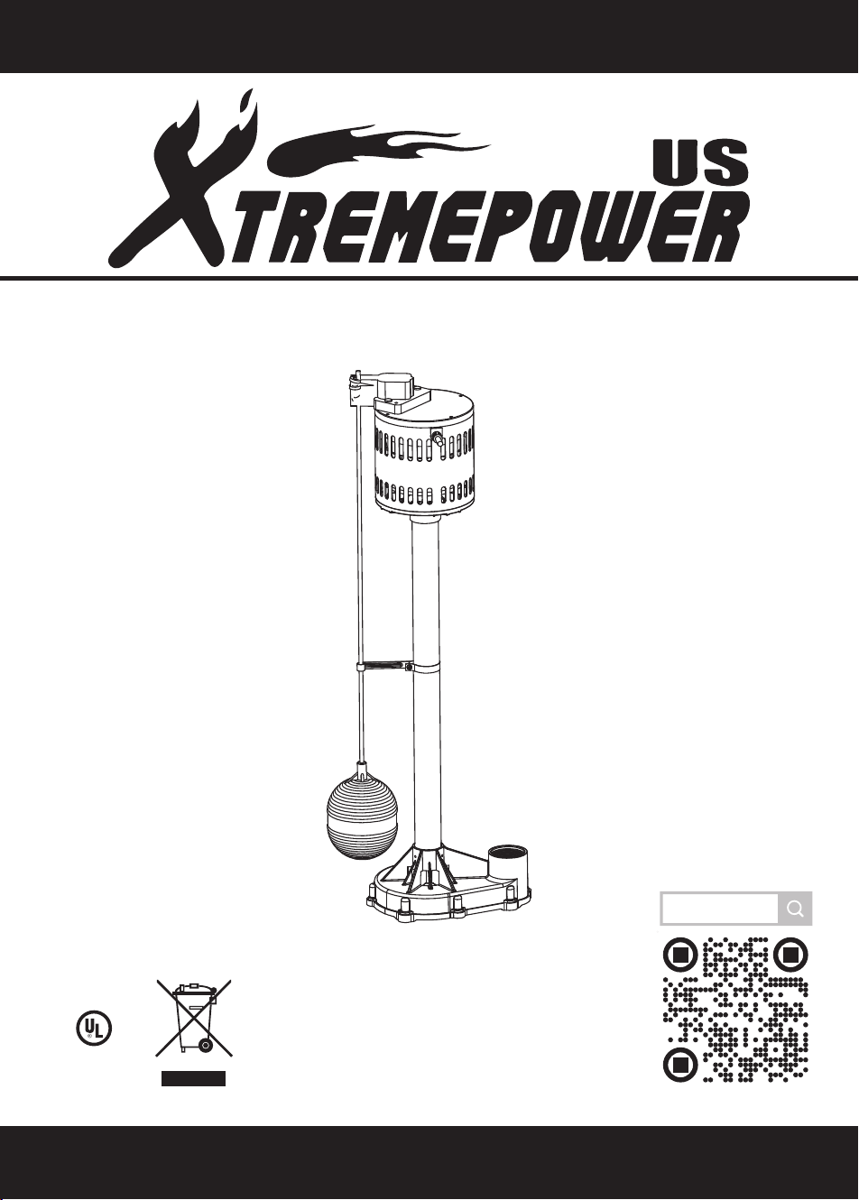
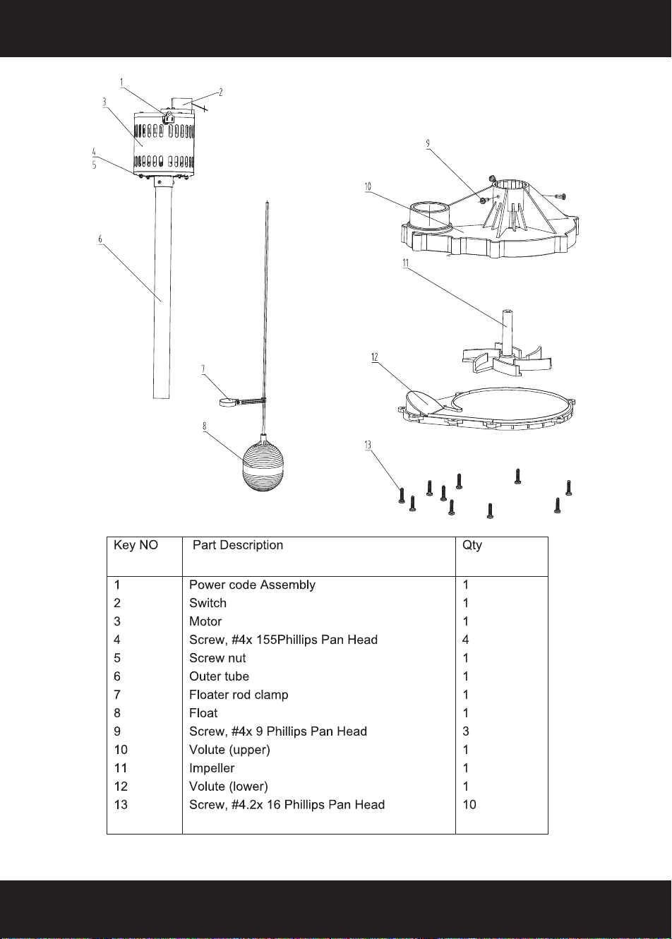
ITEM DIAGRAM
2

DESCRIPTION
This submersible sump pump is designed for home sumps. Unit is equipped with a 3-prong
grounding-type power cord. Shaded – pole motor is oil filled and sealed for cooler running. Sleeve
bearings on motor shaft never need lubrication. Automatic reset thermal protection. Not designed for
use a swimming pool drainer.
NOTICE: Do not reduce size of discharge pipe or hose below1-1/4” diameter. If discharge is too small,
pump will overheat and fail prematurely.
NOTICE: This unit is not designed for applications involving salt water or brine! Use with salt water or
brine will void warranty.
Pump water only with this pump.
Do not use where water recirculates.
Not designed for use as a swimming pool.
GENERAL SAFETY INFORMATION
Electricity powered sump pumps normally give many years of trouble- free service when correctly
installed, maintained, and used. However, unusual circumstances (interruption of power to the pump,
dirt/ debris in the sump, flooding that exceeds the
pump’s capacity, electrical or mechanical failure in
Technical data
Model
Nominal voltage
Horsepower
Protection type
Max. Flow Rate
Max. Head
Current rating
76081
115 V / 60 Hz
1/3HP
IPX4
4 A
3000gph
18ft
This Pump Has Been Evaluated for Use With Water
Only
WARNING -“Risk of electric shock - This pump is
supplied with a grounding conductor and grounding
type attachment plug. To reduce the risk of electric
shock, be certain that it is connected only to proper-
ly grounded, grounding-type receptacle”.
CAUTION !
3
SPECIFICATIONS AND SAFETY

the pump, etc.) may prevent your pump from functioning normally. To prevent possible water damage
due to flooding, consult your retailer about a secondary AC sump pump, a CD backup sump pump, and/
or a high water alarm. See the “ Trouble shooting Chart” in this manual for information about common
sump pump problems and remedies.
1. Know the pump application, limitations, and potential hazards.
2. Do not use in water with fish present.
3. Disconnect power before servicing.
4. Release all pressure within system before servicing any component.
5. Drain all water from system before servicing.
6. Secure discharge line before starting pump. An unsecured discharge line will whip, possibly
causing personal injury and/ or property damage.
7. Check hoses for weak or worn condition before each use, making certain that all connections are
secure.
8. Periodically inspect sump, pump and system components. Keep free of debris and foreign
objects .Perform routine maintenances
as required.
9. Provide means of pressure relief for pumps whose
discharge line can be shut-off or obstructed.
10. Personal safety:
a. Wear safety glasses at all times when working with pumps.
b. Keep work area clean, uncluttered ad properly lighted – replace all unused tools and
equipment.
c. Keep visitors at a safe distance from work area.
d. Make workshop child – proof – with padlocks, master switches, and by removing starter keys.
11. When wiring an electrically driven pump, follow all electrical and safety codes that apply.
12. This equipment us only for use on 115 volt ( single phase ) and is equipped with an approved 3 –
conductor cord and 3 – prong, grounding – type plug.
To reduce risk of electric
shock, pull plug before servicing. This pump has not been
investigated for use in swimming pool area. Pump is supplied with a grounding conductor and
grounding – type attachment plug. Be sure it is connected only to a properly grounded grounding – type
receptacle.
Where a 2 – prong wall receptacle is encountered, it must be replaced with properly grounded 3 – prong
receptacle installed in accordance with codes and ordinances that apply.
13. All wiring should be performed by a qualified electrician.
14. Make certain power source conforms to requirements of your equipment.
15. Protect electrical cord from sharp objects, hot surfaces, oil, and chemicals. Avoid kinking cord.
Replace or repair damaged or worn cords immediately.
16. Do not touch an operating motor. Modern motors can operate at high temperatures.
17. Do not handle pump or pump motor with wet hands or when standing on wet damp surface or in
water.
Hazardous voltage can shock, burn or kill. If you basement has water or
moisture on floor, do not walk on wet area until all
power has been turned off. If shut – off box is
basement, call electric company or hydro authority to
shut – off service to house, or call your local
fire department for instructions. Remove pump and r
epair or replace. Failure to follow this warning
can result in fatal electrical shock.
Do not lift pump by power cord.
WARNING
WARNING
4
SPECIFICATIONS AND SAFETY
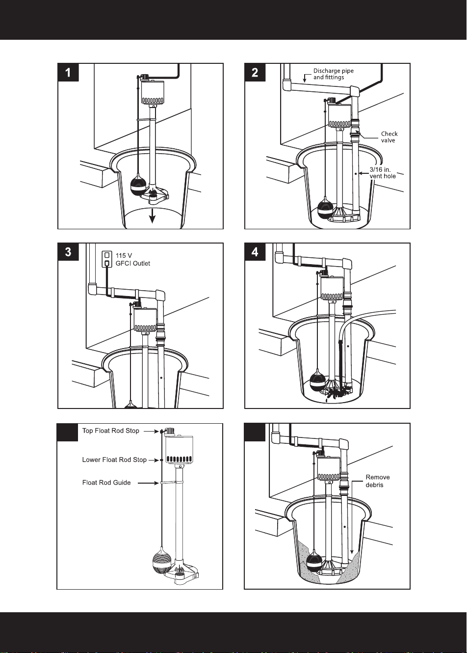
FLOAT SWITCH INSTALLATION
Models equipped with vertical switches require some assembly. See the Switch Assembly instructions
on Page4. Models with tethered float switches are ready for use.
INSTRUCTION
1. Install pump in sump pit with minimum diameter of 10” (254mm) for models equipped with
vertical switches and 14” (356mm) for tethered float switch models. Sump depth should be 16”
(406mm) for tethered models and 10” (254mm) for vertically switched models. Construct sump
pit of tile, concrete, steel or plastic. Check local codes for approved materials and for proper
installation.
2. Install pump in pit so that switch operating mechanism has maximum possible clearance.
3. Pump should not be installed on clay, earth or sand surface. Clean sump pit of small stones and
gravel which could clog pump. Keep pump inlet screen clear.
NOTICE: Do not use ordinary pipe joint compound on plastic pipe. Pipe joint compound can
attack plastics.
4. Install discharge plumbing
. Use rigid plastic pipe and wrap threads with Teflon™ tape. Screw
pipe into pump hand tight plus 1-1/2 turns.
Risk of flooding. If a flexible discharge hos
e is used, make sure pump is secured in
sump to prevent movement. Failure to secure pump may allow pump movement, switch
interference and prevent pump from starting or stopping.
5. To reduce motor noise and vibrations, a short length of rubber hose (1-7/8" (47.6mm) I.D., e.g.
radiator hose) can be connected into discharge line near pump using suitable clamps.
6. Install an in-line check valve (Flotec No. FP0026- 10D) or an in-pump check valve to prevent
flow backwards through pump when pump shuts off.
NOTICE: If your check valve is not equipped with an air bleed hole to prevent air locking pump, drill a
1/8" (3.2 mm) hole in discharge pipe just above where the discharge pipe screws into the
pump
discharge. Be sure the hole is below the waterline and the check valve to prevent air locks.
7. Power Supply: Pump is designed for 115 V.
60 Hz operation and requires a minimum 15 amp
individual branch circuit. Both pump and switch are supplied with 3-wire cord sets with
grounding-type plugs. Switch plug is inserted directly into outlet and pump plug inserts into
opposite end of switch plug.
Pump should always be electrically grounded to a suitable electrical ground such as a
grounded water pipe or a properly grounded metallic raceway, or ground wire system.
Do not cut off round ground pin.
8. If pump discharge line is exposed to outside subfreezing atmosphere, portion of line exposed must
be installed so any water remaining in pipe will drain to the outfall by gravity. Failure to do this can
cause water trapped in discharge to freeze which could result in damage to pump.
9. After piping, check valve and float switch have been installed, the unit is ready for operation.
10. Check the pump operation by filling sump wi
th water and observing pump operation through one,
complete cycle. For switch settings see the Electrical and Switch Specifications chart on Page 2.
Failure to make this operational check may lead to improper operation, premature
failure, and flooding.
CAUTION
WARNING
WARNING
5
FLOAT SWITCH INSTALLATION
6
FLOAT SWITCH INSTALLATION
6
5
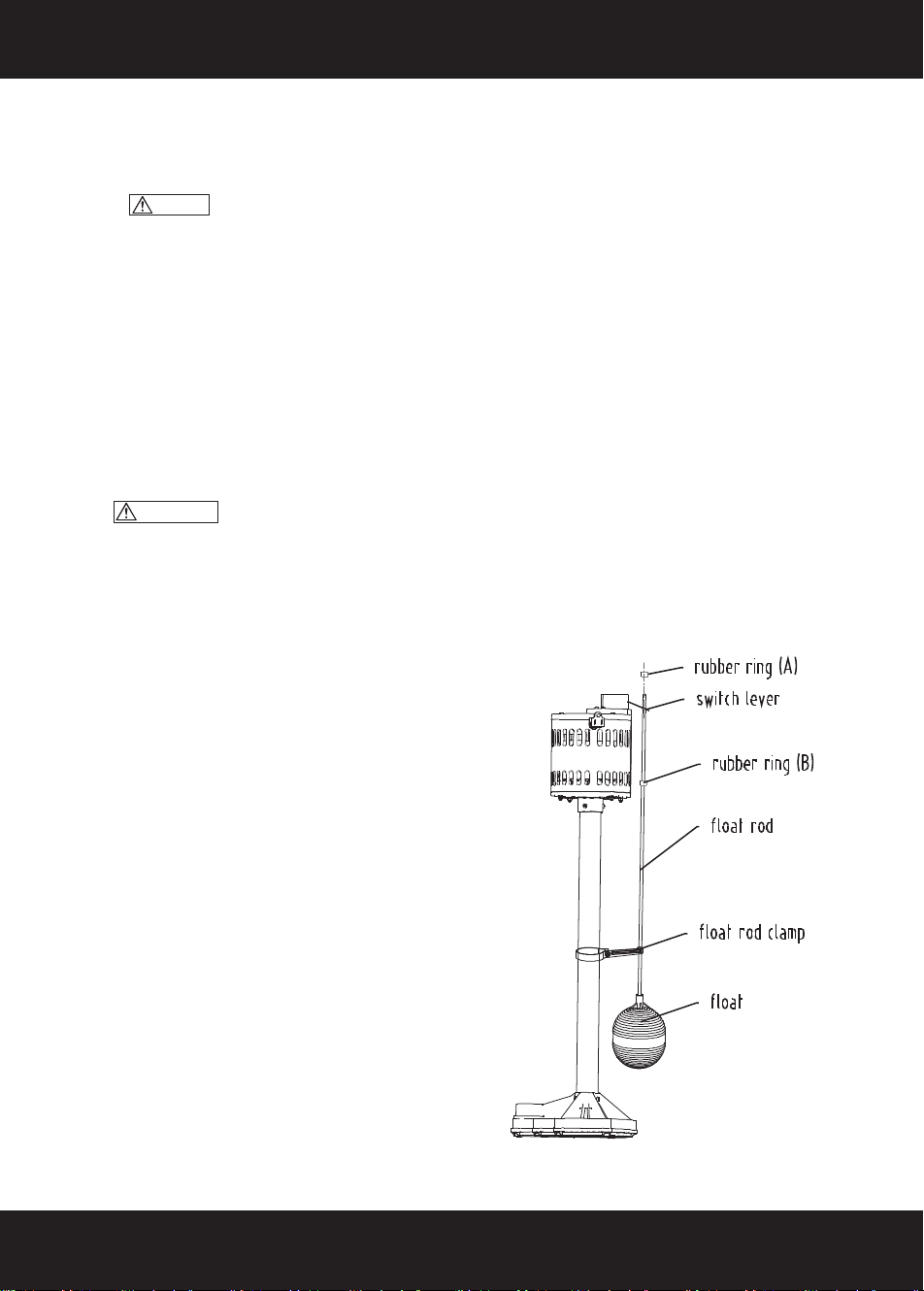
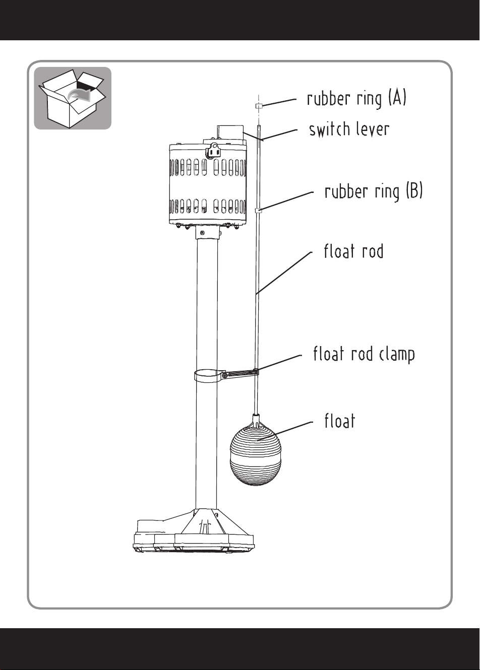
Vertical Switch Assembly
1> Mount on the float with the float rod.
2> Mount the float rod clamp
3> Mount a rubber ring B at a distance from the
upper of the float rod.
4> Install the components throw into the top of
the float rod.
NOTICE: Be sure the switch lever between
the rubber ring A and the rubber ring B.
NOTICE: Attach the switch
to the pump as shown.
NOTICE: Be sure that the float rod clamp
at about 450mm from the ground.
OPERATION
Risk of electric shock. Do not handle a pump or pump motor with wet hands or
when standing on wet or damp surface, or in water.
1. Shaft seal depends on water for lubrication. Do not operate pump unless it is submerged in
water as seal may be damaged if allowed to run dry.
2. Motor is equipped with automatic reset thermal protector. If temperature in motor should
rise unduly, switch will cut off all power before damage can be done to motor. When motor
has cooled sufficiently, switch will reset automatically and restart motor. If protector trips
repeatedly, pump
should be removed and checked as to cause of difficulty. Low voltage,
long extension cords, clogged impeller, very low head or lift, or a plugged or frozen
WARNING
3. Pump will not remove all water. If operating a pump manually, and suddenly no water
comes out of the discharge hose, shut off the unit immediately. The water level is
probably very low and the unit has broken prime.
Risk of electric shock . Before attempting to check why unit has stopped
operating, disconnect power from unit.
discharge pipe, etc., could cause cycling.
WARNING
7
OPERATION
8
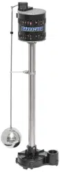
COMPONENT DIAGRAM
9
TROUBLESHOOTING
10
PARTS LIST
11
PARTS LIST
PARTS#
NO. ITEM
QTY
UNIT
P76081-0010
0010 FLOATING BALL
1
PCS
P76081-0020
0020 FLOATER
1
PCS
P76081-0030
0030 CROSS HEAD TAPPING SCREW
1
PCS
P76081-0040
0040 BUSHING
1
PCS
P76081-0050
0050 HEXAGON NUT
1
PCS
P76081-0060
0060 TAPPING SCREW
6
PCS
P76081-0070
0070 MOTOR FRONT COVER
1
PCS
P76081-0080
0080 BEARING
1
PCS
P76081-0090
0090 FAN
1
PCS
P76081-0100
0100 ROTOR
1
PCS
P76081-0110
0110 SHAFT RETAINING RING
2
PCS
P76081-0120
0120 STATOR
1
PCS
P76081-0130
0130 MOTOR OUTER HOUSING
1
PCS
P76081-0140
0140 PLUG CORD
1
PCS
P76081-0150
0150 BEARING
1
PCS
P76081-0160
0160 CORRUGATED GASKET
1 PCS
P76081-0170
0170 CROSS HEAD TAPPING SCREW
2
PCS
P76081-0180
0180 CAPACITOR
1
PCS
P76081-0190
0190 EXTERNAL SERRATED LOCK WASHER
1
PCS
P76081-0200
0200 TIE
4 PCS
PARTS# NO. ITEM QTY UNIT
P76081-0210 0210 NYLON SECURE LINE PRESSING CAP 1 PCS
P76081-0220 0220 NYLON SECURE LINE PRESSING CAP 2 PCS
P76081-0230
0230 SP
RING WAS
HER 2 PCS
P76081-0240 0240 MOTOR REAR COVER 1 PCS
P76081-0260 0260 CROSS HEAD TAPPING SCREW 4 PCS
P76081-0270 0270 ISOLATION RING 2 PCS
P76081-0280 0280 PUMP SWITCH 1 PCS
P76081-0281 0281 SHIELD 1 PCS
P76081-0290 0290 CROSS HEAD TAPPING SCREW 4 PCS
P76081-0291 0291 PLAIN WASHER 5 PCS
P76081-0300 0300 OUTER TUBE 1 PCS
P76081-0310 0310 INNER TUBE
INSERT 2 PCS
P76081-0320 0320 I
NSIDE TUBE 1 PCS
P76081-0330 0330 PU
MP HOUSING 1 PCS
P76081-0340 0340 IMPELLER 1 PCS
P76081-0350 0350 DIFFUSOR PLATE 1 PCS
P76081-0360 0360 SEAL GASKET 1 PCS
P76081-0370 0370 CROSS HEAD TAPPING SCREW 10 PCS
P76081-0380 0380 GLUE 0.34 FL OZ

CUSTOMER SERVICE
If you have any questions about ordering our outdoor furnitures and replacement parts or other furniture
products, please feel free to contact us using the following contact information:
Customer Service and Technical Support
Phone: (909) 628-0880
Email: [email protected]
Hours of Operation: Monday – Friday, 9AM – 4PM (CST)
DISCLAIMER
PLEASE READ THE FOLLOWING CAREFULLY
The manufacturer and/or distributor have provided the parts list and assembly diagram in this manual for
reference purposes only. They do not make any representation or warranty to the buyer that they are qualified
to make repairs to the product or replace any parts of the product. In fact, the manufacturer and/or distributor
expressly state that all repairs and parts replacements should be undertaken by certified and licensed
technicians, and not by the buyer.
The buyer assumes all risk and liability arising from their repairs to the original product or replacement parts
or arising from their installation of replacement parts. It is strongly advised that qualified professionals handle
any repairs or replacements to ensure safety and proper functioning of the product. Improper installation and
operation may result in injury, property damage, or voiding of warranty. The manufacturer and/or distributor
shall not be held responsible for any accidents, damages, or malfunctions resulting from the buyer's
installation and operation of the product. It is essential to follow all safety guidelines and recommendations
provided in this manual and to seek professional assistance if unsure about the installation or operation
procedures.