USER GUIDE
Mini Split Indoor/Outdoor Air Conditioner Unit
Start Here
Serenelifehome.com/
register
PLEASE KEEP THIS MANUAL CAREFULLY FOR FUTURE REFERENCE.
FOR HOUSEHOLD USE ONLY.
TABLE OF CONTENTS
Features and Technical Specs
SAFETY PRECAUTIONS
NAME OF PARTS
REMOTE CONTROL
OPERATION INSTRUCTIONS
Instructions for Servicing (R454B)
INSTALLATION PRECAUTIONS
Indoor Unit Installation
Outdoor Unit Installation
Test Operation
Maintenance
Troubleshooting
Register Product
3
5
8
9
21
22
27
31
37
42
43
45
47
• The design and specications are subject to change without prior notice for product
improvement. Consult with the sales agency or manufacturer for details.
• The shape and position of buttons and indicators may vary according to the
model, but their functions are the same.
www.SereneLifeHome.com
2
California Prop 65 Warning
WARNING:
This product may expose you to chemicals, which is known to
the state of California to cause cancer, birth defects and other
reproductive harm. Do not ingest.
For more info go to: www.P65warnings.ca.gov
www.SereneLifeHome.com
3
Features:
• Ecient and Powerful Cooling and Heating
• WiFi Function for Enhanced Convenience and Smart Control
• Ensures Precise Airow and Temperature Adjustments
• Provides Self-Diagnostic Function and Digital Display
• Energy Saving Mode, Programmable Dry Function, and Auto Fan Speed Control
• Ultra-Quiet Performance for Optimal Personal Comfort
• Auto Restart After Power Failure
• Features Timer, Auto-Defrost, Sleep Mode, and Intelligent Compressor
• Lightweight Wall-Mounted Indoor Mini Split Unit
• Hassle-Free, Quick Set-up Cooling & Heating
• Convenient Wide-Area Climate Control for Homes, Oces, Schools & Businesses
• Modern Style with Durable Plastic Body Housing
• Energy Ecient with Low Power Consumption
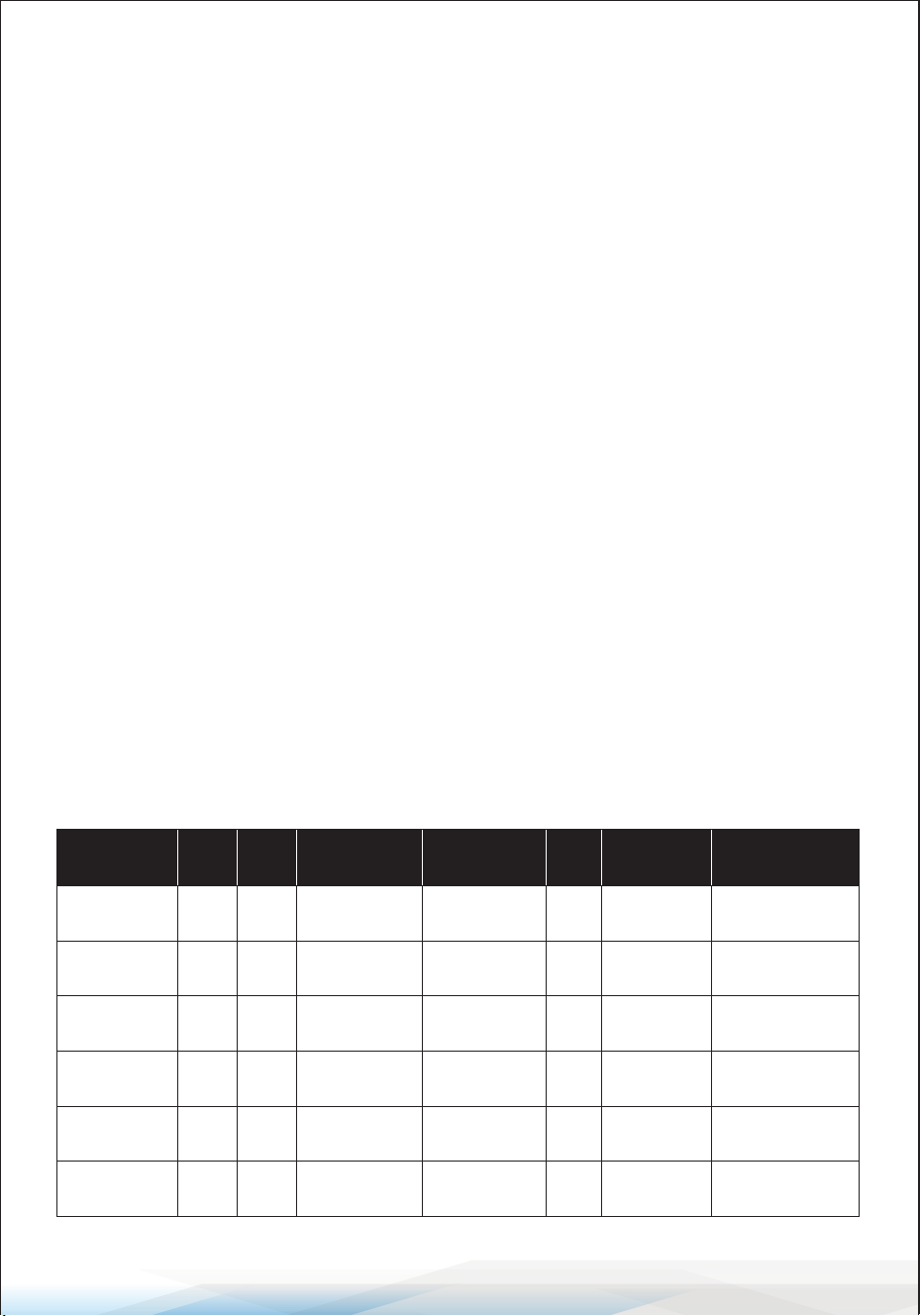
Indoor Mini Split Unit Technical Specications
Model
Cooling
Power
(BTU)
Dimensions
(L x W x H)
9,000 8” x 31.9” x 11.5”
SLSPLT9IN
Power Supply
115V/60Hz
Annual Energy
Consumption
(kW/h)
979.14
SEER
19
Coverage Area
(sq. ft.)
Up to 400
9,000 8” x 31.9” x 11.5”SLSPLT9IN20SR 208/230V~/60Hz965.04 20 Up to 400
12,000 8” x 31.9” x 11.5”SLSPLT12IN 115V/60Hz1,215.67 19 Up to 550
12,000 8” x 31.9” x 11.5”SLSPLT12IN21SR 208/230V~/60Hz1,198.75 21 Up to 550
18,000 8.7” x 39.8” x 12.4”SLSPLT18IN 208/230V~/60Hz1,825.45 20 Up to 1,000
24,000 10.2” x 46.9” x 14.2”SLSPLT24IN 208/230V~/60Hz2,412.89 18 Up to 1,500
Heating
Power
(BTU)
9,800
9,800
12,500
12,500
19,500
25,000
www.SereneLifeHome.com
4
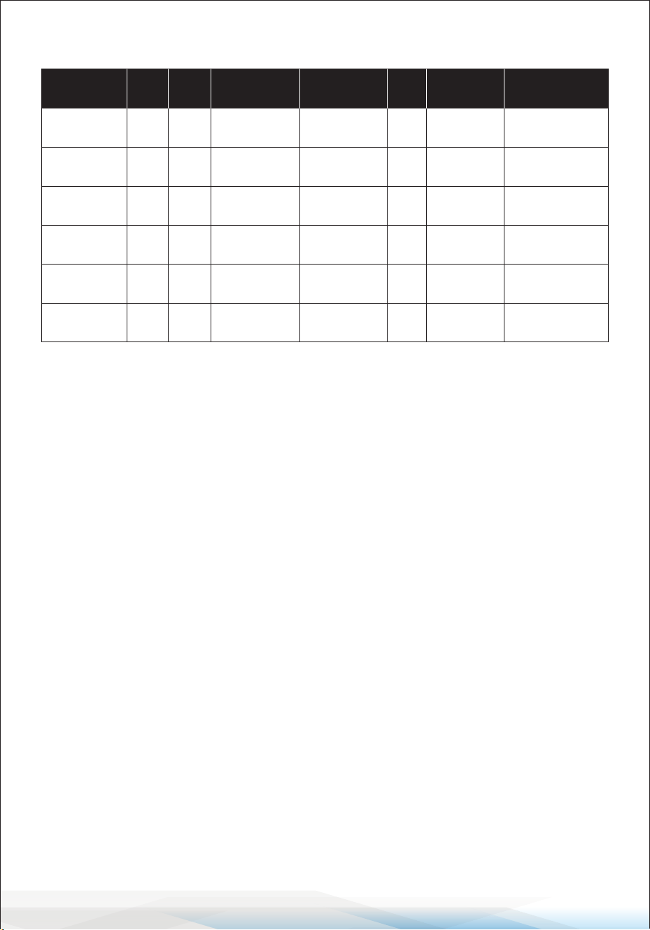
Outdoor Mini Split Unit Technical Specications
What's in the Box
• Indoor/Outdoor Mini Split Unit
• 5.8 Meters (19 ft.) Connecting Wire
• 5 Meters (16.4 ft.) Copper Pipe (for outdoor units)
• Remote Control
• Drainage Hose
• Outdoor Anti-Shake Gasket
• Drainage Mouth
• Insulation Casing (for outdoor units)
• Sealing Colloid (for outdoor units)
• Plastic Packing Bag (for outdoor units)
• Vinyl Tape (for outdoor units)
• Wall Socket (for outdoor units)
• Wall Cover (for outdoor units)
Model
Dimensions
(L x W x H)
19.6 x 31 x 11.4
SLSPLT9OT
Power Supply
115V/60Hz
Annual Energy
Consumption
(kW/h)
979.14
SEER
19
Coverage Area
(sq. ft.)
Up to 400
19.6 x 31 x 11.4
SLSPLT9OT20SR
115V/60Hz965.04 20 Up to 400
19.6 x 31 x 11.4SLSPLT12OT20SR 208/230V~/60Hz1,215.67 19 Up to 550
19.6 x 31 x 11.4
SLSPLT12OT21SR
208/230V~/60Hz1,198.75 21 Up to 550
23.7 x 34 x 13.7SLSPLT18OT 208/230V~/60Hz1,825.45 20 Up to 1,000
27.5 x 36.5 x 15SLSPLT24OT 208/230V~/60Hz2,412.89 18 Up to 1,500
Cooling
Power
(BTU)
9,000
9,000
12,000
12,000
18,000
24,000
Heating
Power
(BTU)
9,800
9,800
12,500
12,500
19,500
25,000

www.SereneLifeHome.com
5
SAFETY PRECAUTIONS
SAFETY RULES AND RECOMMENDATIONS FOR THE INSTALLER
1. Read this guide before installing and using the appliance.
2. During the installation of the indoor and outdoor units, access to the working
area should be restricted to prevent children from entering.
Unforeseeable accidents could happen.
3. Ensure that the base of the outdoor unit is rmly xed.
4. Check that air cannot enter the refrigerant system and inspect for refrigerant
leaks when moving the air conditioner.
5. Perform a test cycle after installing the air conditioner and record the
operating data.
6. Protect the indoor unit with a fuse of suitable capacity for the maximum input
current, or with another overload protection device.
7. Ensure that the mains voltage corresponds to the rating specied on the rating
plate. Keep the switch or power plug clean. Insert the power plug correctly
and rmly into the socket, thereby avoiding the risk of electric shock or re
due to insucient contact.
8. Check that the socket is compatible with the plug. If not, have the socket
replaced.
9. The appliance must be tted with a means of disconnection from the supply
mains, having contact separation in all poles that provides full disconnection
under "over voltage category III conditions." These means must be incorporated
into the xed wiring in accordance with the wiring rules.
10. The air conditioner must be installed by a professional or qualied person.
11. Do not install the appliance less than 50 cm from ammable substances
(alcohol, etc.) or from pressurized containers (e.g., spray cans).
12. If the appliance is used in areas without proper ventilation, precautions must
be taken to prevent refrigerant gas leaks from remaining in the environment
and creating a re hazard.
13. The packaging materials are recyclable and should be disposed of in the
separate waste bins. Take the air conditioner at the end of its useful life to a
special waste collection center for disposal.
14. Only use the air conditioner as instructed in this manual. These instructions
are not intended to cover every possible condition and situation. As with any
electrical household appliance, common sense and caution are always
recommended for installation, operation, and maintenance.

www.SereneLifeHome.com
6
15. The appliance must be installed in accordance with applicable national
regulations.
16. Before accessing the terminals, ensure all power circuits are disconnected
from the power supply.
17. The appliance should be installed according to national wiring regulations.
18. This appliance can be used by children aged 8 years and above and by persons
with reduced physical, sensory, or mental capabilities, or lack of experience
and knowledge, if they have been given supervision or instruction on using
the appliance safely and understand the hazards involved. Children shall not
play with the appliance. Cleaning and user maintenance should not be
performed by children without supervision.
19. Do not try to install the air conditioner by yourself; always contact specialized
technical personnel.
20. Cleaning and maintenance must be carried out by specialized technical
personnel. In any case, disconnect the appliance from the mains electricity
supply before performing any cleaning or maintenance.
21. Ensure that the mains voltage corresponds to the rating on the rating plate.
Keep the switch or power plug clean. Insert the power plug correctly and
rmly into the socket to avoid the risk of electric shock or re due to
insucient contact.
22. Do not pull out the plug to switch o the appliance when it is in operation,
as this could cause a spark and lead to a re.
23. This appliance is designed for air conditioning domestic environments and
must not be used for any other purpose, such as drying clothes, cooling
food, etc.
24. Always use the appliance with the air lter installed.
Operating the air conditioner without the air lter could lead to an excessive
accumulation of dust or debris inside the unit, potentially causing failures.
25. The user is responsible for ensuring that the appliance is installed by a qualied
technician, who must check that earthing/grounding is done according to
current legislation and install a thermomagnetic circuit breaker.
26. The batteries in the remote control must be recycled or disposed of properly.
For disposal of used batteries, please discard them as sorted municipal waste
at the designated collection point.
27. Never remain directly exposed to the ow of cold air for long periods.
Prolonged exposure to cold air can be harmful to your health. Extra care should
be taken in rooms with children, elderly individuals, or those in poor health.
28. If the appliance emits smoke or there is a burning smell, immediately
disconnect the power supply and contact the Service Center.

www.SereneLifeHome.com
7
29. Prolonged use of the device under such conditions could result in re or
electrocution.
30. Repairs should only be carried out by an authorized Service Center of the
manufacturer. Incorrect repairs could expose the user to the risk of electric
shock.
31. If you do not intend to use the device for a long period, disconnect the
automatic switch. Ensure the airow direction is properly adjusted.
32. The aps should be directed downward in heating mode and upward in
cooling mode.
33. Ensure that the appliance is disconnected from the power supply when it
will remain unused for a long period, and before performing any cleaning or
maintenance.
34. Selecting the most suitable temperature can prevent damage to the appliance.
SAFETY RULES AND PROHIBITIONS
1. Do not bend, tug, or compress the power cord, as this could damage it.
A damaged power cord can cause electrical shocks or re.
Only specialized technical personnel should replace a damaged power cord.
2. Do not use extensions or multi-plug adapters.
3. Do not touch the appliance when barefoot or when parts of your body are
wet or damp.
4. Do not obstruct the air inlet or outlet of either the indoor or outdoor unit.
Obstructions will reduce the operational eciency of the air conditioner and
could cause failures or damage.
5. Do not alter the appliance’s characteristics in any way.
6. Do not install the appliance in environments where the air may contain gas,
oil, or sulfur, or near sources of heat.
7. This appliance is not intended for use by persons (including children) with
reduced physical, sensory, or mental capabilities, or lack of experience and
knowledge, unless they have been given supervision or instruction regarding
its safe use by a responsible person.
8. Do not climb onto or place any heavy or hot objects on top of the appliance.
9. Do not leave windows or doors open for long periods when the air conditioner
is operating.
10. Do not direct the airow onto plants or animals.
www.SereneLifeHome.com
8
11. Prolonged direct exposure to cold air from the air conditioner could have
negative eects on plants and animals.
12. Do not allow the appliance to come into contact with water.
This could damage the electrical insulation and lead to electrocution.
13. Do not climb onto or place objects on the outdoor unit.
14. Never insert sticks or similar objects into the appliance, as this could cause
injury.
15. Children should be supervised to ensure that they do not play with the
appliance. If the power cord is damaged, it must be replaced by the
manufacturer, its service agent, or similarly qualied persons to avoid a hazard.
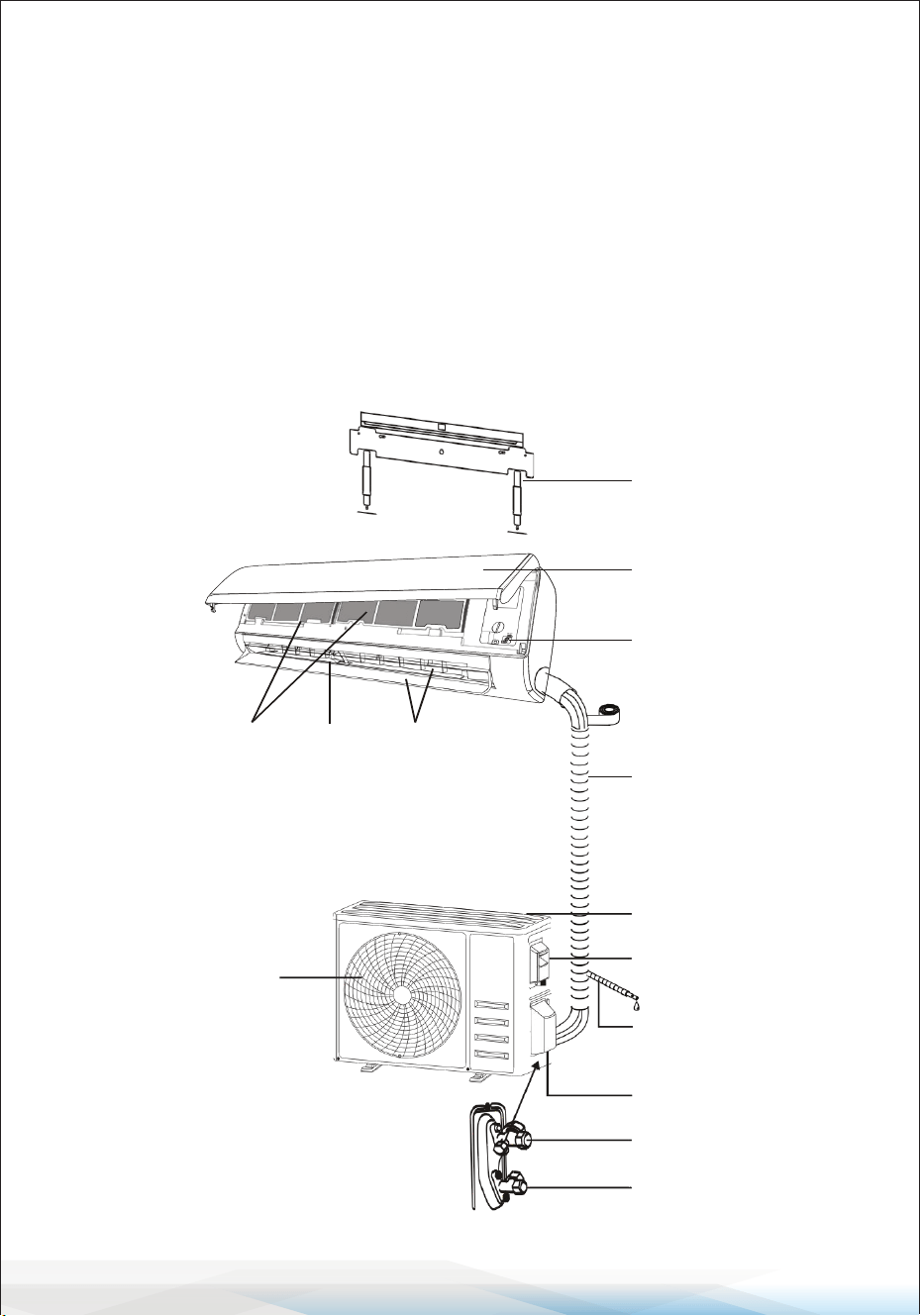
NAME OF PARTS
Indoor Unit
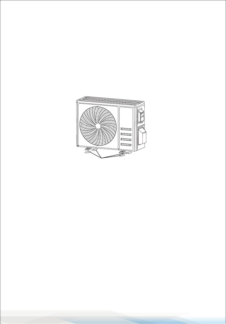
Outdoor Unit
Mounting plate
Front panel
Emergency button
Refrigerant connecting
pipe
Air inlet
Drainage pipe
Valve protective cover
Gas valve
(Low pressure valve)
Liquid valve
(High pressure valve)
Air outlet
Air lter
Wiring cover
Air outlet Air deector
and ap
With the protective cover removed
Note: The gure shown may dier from
the actual product. Please consider the
actual product as the standard.
www.SereneLifeHome.com
9
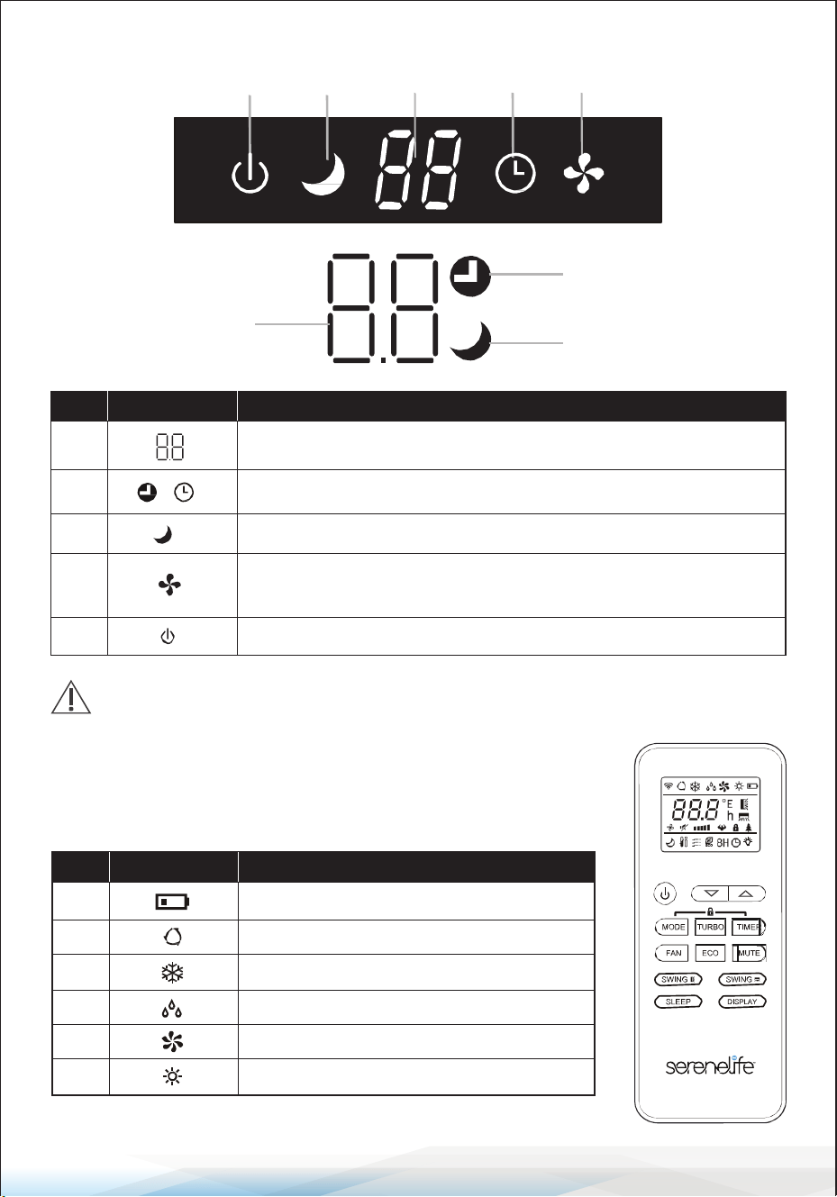
Indoor Display
REMOTE CONTROL
Remote control DISPLAY
5 3 1 2 4
2
1
3
No. LED
Function
1 Indicator for Timer, temperature, and error codes.
2 Lights up during Timer operation.
3 SLEEP mode
4
The symbol appears when the unit is turned on and disappears
when the unit is turned o.
5 The symbol appears when power is on.
The shape and position of switches and indicators may vary by model,
but their functions are the same.
No. Symbols
Meaning
1 Battery indicator
2 Auto Mode
3 Cooling Mode
4 Dry Mode
6 Heating Mode
Fan only Mode5
www.SereneLifeHome.com
10
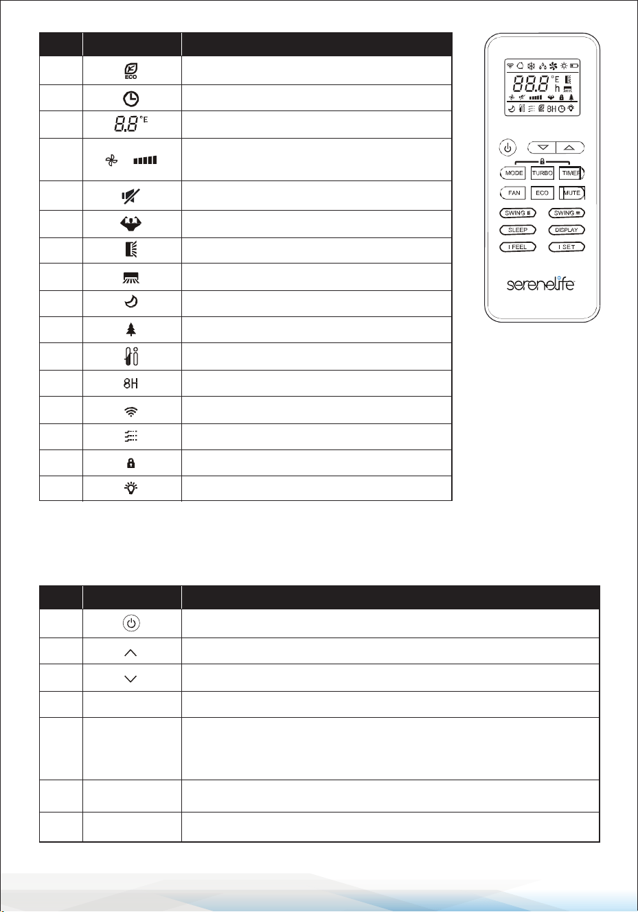
REMOTE CONTROL
The display and certain functions of the remote control may vary depending on the model.
No. Symbols
Meaning
7 ECO Mode
8 Timer
9 Temperature indicator
10
Fan speed:
Auto/low/low-mid/mid/mid-high/high
11 Mute function
12 TURBO function
13 Up-down auto swing
14 Left-right auto swing
15 SLEEP function
17 I FEEL function
Health function16
18 8 heating function
19 Signal indicator
20 Gentle wind
Child-Lock21
Display ON/OFF22
No. Button
Function
1 To turn the air conditioner on/o.
2 To increase the temperature or adjust the timer setting in hours.
3 To decrease the temperature or adjust the timer setting in hours.
4 To select the mode of operation (AUTO, COOL, DRY, FAN, HEAT)
To activate/deactivate the ECO function.
Press and hold to activate/deactivate the 8°C/46.4°F heating function
(depending on the model).
5
6 To activate/deactivate the TURBO function.
7 To select the fan speed: auto, low, medium, or high.
MODE
ECO
TURBO
FAN
www.SereneLifeHome.com
11
Notes:
• The display and certain functions of the remote control may vary depending
on the model.
• The shape and position of buttons and indicators may dier between models,
but their functions remain the same.
• The unit conrms the correct reception of each button press with a beep.
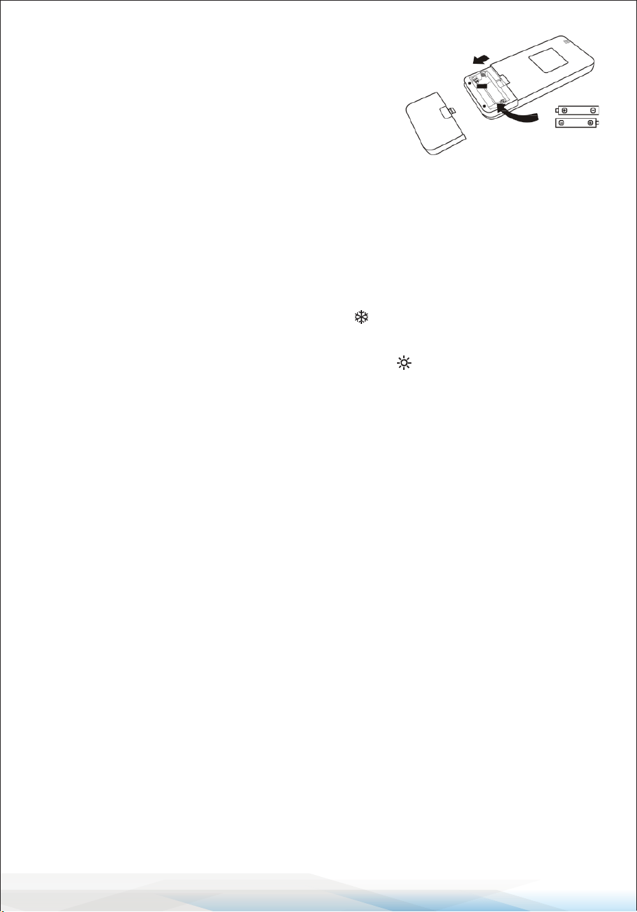
Replacement of Batteries
1. Remove the battery cover plate from the back of the remote control by sliding
it in the direction indicated by the arrow.
2. Install the batteries, ensuring they are inserted according to the (+) and
(-) markings shown on the remote control.
3. Reinstall the battery cover by sliding it back into place.
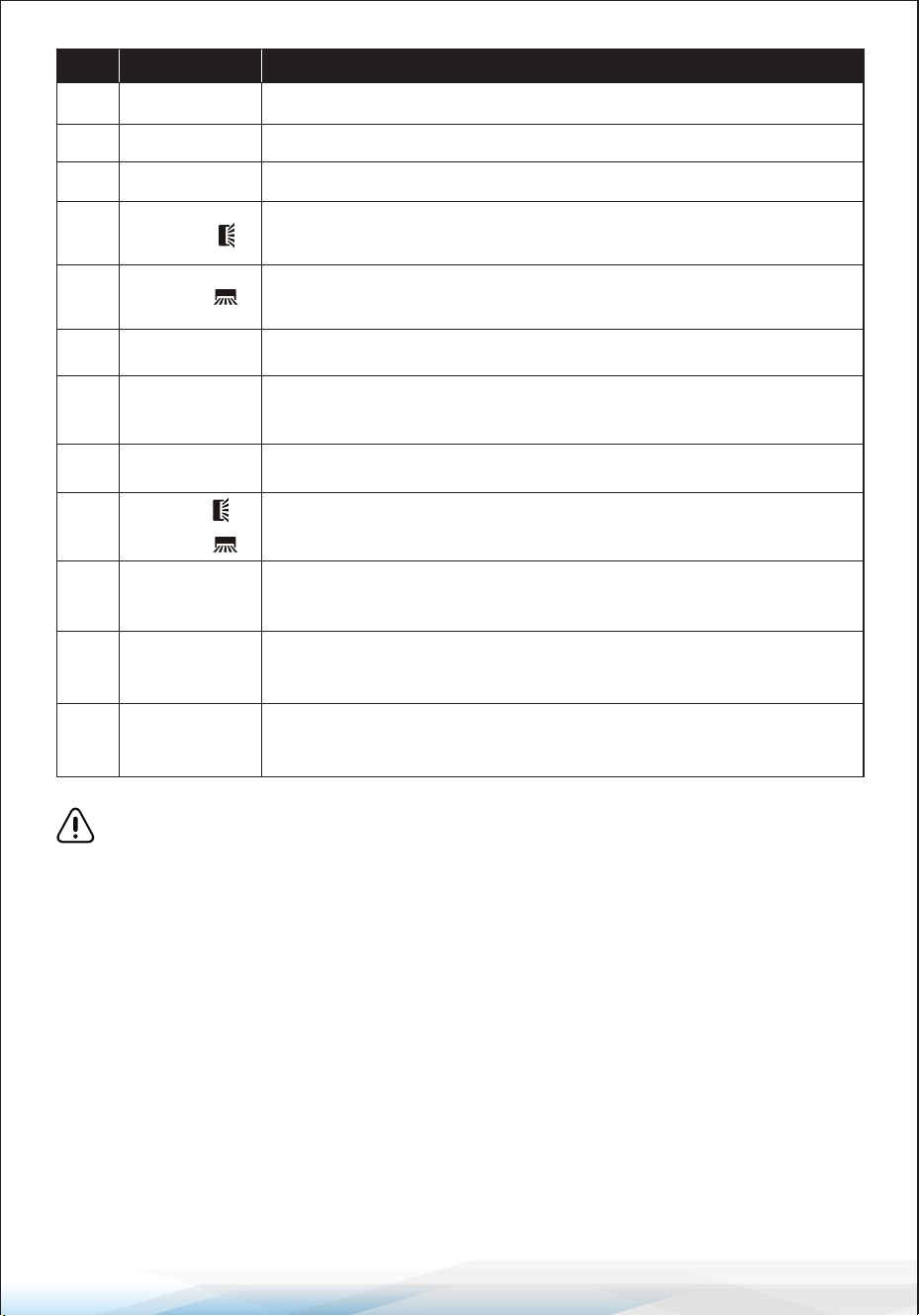
No. Button
Function
8 To set the timer for on/o operation.
9 To turn the SLEEP function on/o.
10 To turn the LED display on/o.
11
To start or stop horizontal ap movement
or adjust the up/down airow direction.
12
13 To turn the I FEEL function on/o.
14
To turn the MUTE function on/o. Press and hold to activate/
deactivate the GEN function (depending on the model).
SWING
SWING
I FEEL
MUTE
TIMER
SLEEP
DISPLAY
To start or stop vertical deector movement
or adjust the left/right airow direction.
15 To activate/deactivate the CHILD-LOCK function.
MODE + TIMER
16
To activate/deactivate the SELF-CLEAN function
(depending on the model).
SWING
+
SWING
17
To activate/deactivate the GENTLE WIND function
(depending on the model).
FAN + MUTE
18
SLEEP + DISPLAY
To activate/deactivate the HEALTH function
(depending on the model).
19
To memorize the temperature, mode,
and fan speed settings as needed.
I SET
www.SereneLifeHome.com
12
Battery Requirements:
• Use 2 LRO3 AAA (1.5V) batteries.
Do not use rechargeable batteries.
• Replace old batteries with new ones of the
same type when the display becomes illegible.
• Do not dispose of batteries as unsorted municipal
waste. Dispose of them separately to ensure proper
treatment and recycling.
Initial Setup for Certain Models
For some models, after inserting batteries for the rst time, you can congure
the remote control for Cooling only or Heat pump operation. Follow these steps:
1. Press and hold the MODE button until the ( ) icon ashes to set the Cooling
only type.
2. Press and hold the MODE button again until the ( ) icon ashes to set the
Heat pump type.
Note: If the remote control is set to Cooling mode, it will not be possible to
activate the Heating function on units equipped with a Heat pump.
To reset, remove the batteries and reinstall them, then recongure the settings.
Temperature Display Programming
For some models of the remote control, you can toggle the temperature
display between °C and °F:
1. Press and hold the TURBO button for over 5 seconds to enter the change mode.
2. Continue pressing and holding the TURBO button until the display switches
between °C and °F.
3. Release the button and wait for 5 seconds to conrm the selection.
Additional Notes
1. Direct the remote control toward the air conditioner for proper operation.
2. Ensure there are no objects between the remote control and the signal
receptor on the indoor unit.
3. Avoid exposing the remote control to direct sunlight.
4. Keep the remote control at least 3 feet (1 meter) away from televisions or
other electrical appliances.
www.SereneLifeHome.com
13
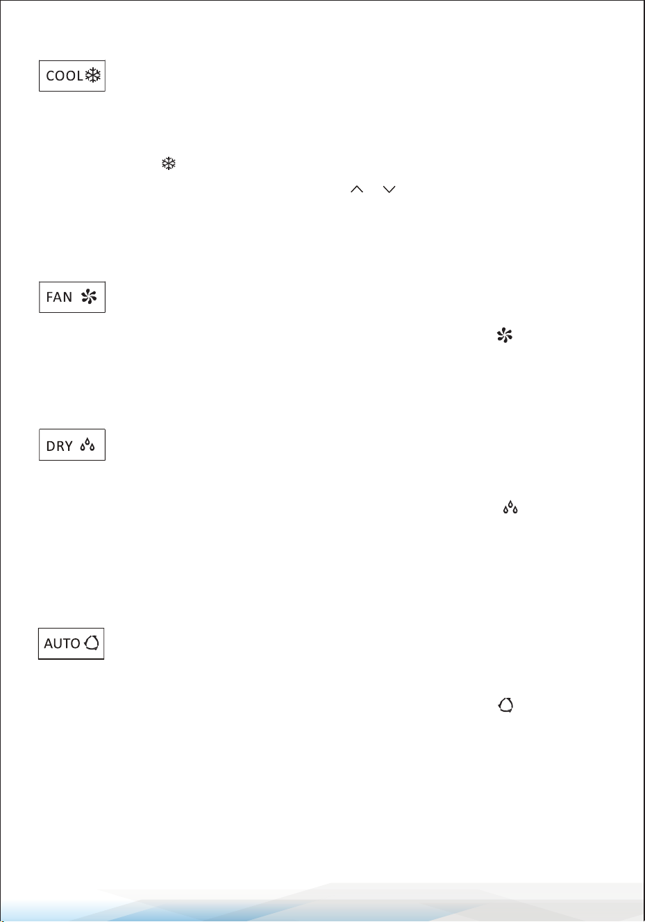
COOLING MODE
The cooling function allows the air conditioner to cool the room and
reduce air humidity simultaneously.
• To activate the cooling function (COOL), press the MODE button until the
cooling symbol appears on the display.
• Use the temperature adjustment buttons ( or ) to set a temperature lower
than the current room temperature.
FAN MODE (Not FAN button)
The FAN mode enables air ventilation only.
• To activate the FAN mode, press the MODE button until the fan symbol
appears on the display.
DRY MODE
The DRY function reduces air humidity to make the room more
comfortable.
• To activate the DRY mode, press the MODE button until the DRY symbol
appears on the display.
• An automatic pre-set function will be activated in this mode.
AUTO MODE
The AUTO mode adjusts the operation automatically based on the
room temperature.
• To activate AUTO mode, press the MODE button until the AUTO symbol
appears on the display.
• The system will automatically select the appropriate mode (cooling, heating, or
fan) based on the detected room temperature.
www.SereneLifeHome.com
14
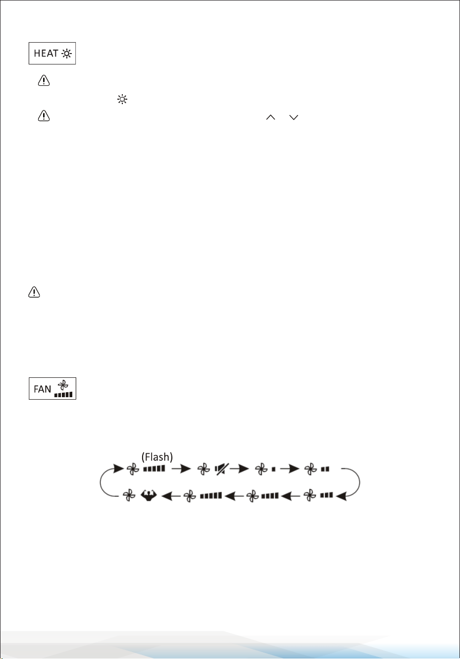
HEATING MODE
The heating function allows the air conditioner to heat the room.
• To activate the heating function (HEAT), press the MODE button until the
heating symbol appears on the display.
• Use the temperature adjustment buttons ( or ) to set a temperature
higher than the current room temperature.
Defrost Cycle: During HEATING mode, the air conditioner may automatically
activate a defrost cycle to remove frost from the condenser and restore its heat
exchange function.
• This defrosting procedure usually lasts for 2–10 minutes, during which the
indoor unit fan will stop operating.
• After defrosting, the system will automatically return to HEATING mode.
(For North American Market)
To start a forced defrost: While in HEATING mode, press the ECO button 10
times within 8 seconds. This will defrost outdoor ice more quickly.
FAN SPEED Function (FAN Button)
The FAN button changes the fan's operating speed.
• Press the FAN button to select the desired fan speed. Options include:
AUTO, MUTE, LOW, LOW-MID, MID, MID-HIGH, HIGH, and TURBO speeds.
CHILD-LOCK Function
The Child-Lock function prevents accidental operation by locking all buttons.
• To activate the Child-Lock function, press and hold the MODE and TIMER
buttons simultaneously.
• To deactivate, repeat the same step.
• While this function is active, no button on the remote control will function.
www.SereneLifeHome.com
15
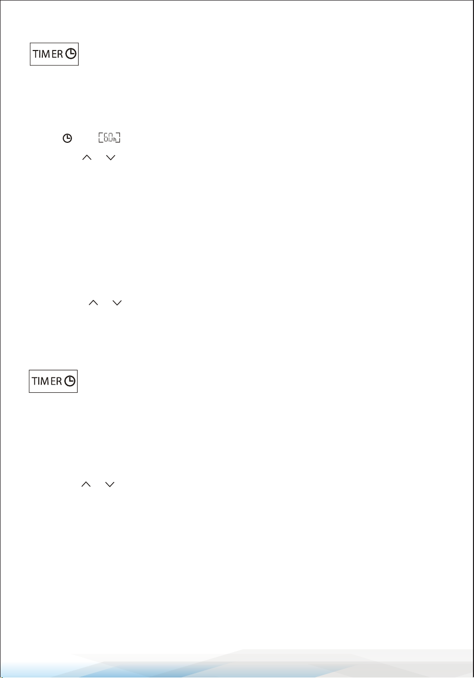
TIMER Function — TIMER ON
The TIMER ON function allows the appliance to automatically switch
on at a pre-set time when it is turned o.
To set the TIMER ON:
1. Press the TIMER button once to activate the switch-on timer.
The and symbols will appear and ash on the remote display.
2. Use the or buttons to set the desired timer-on time:
Each press increases/decreases the time by 30 minutes for intervals between
0 and 10 hours. For intervals between 10 and 24 hours, the time increases/
decreases by 1 hour.
3. Press the TIMER button a second time to conrm the setting.
4. After setting the TIMER ON, congure the desired mode (Cool/Heat/Auto/
Fan/Dry) by pressing the MODE button. Then:
• Set the desired fan speed by pressing the FAN button.
• Use the or buttons to set the desired operation temperature.
To cancel the TIMER ON function, press the TIMER button again.
TIMER Function — TIMER OFF
The TIMER OFF function allows the appliance to automatically switch
o at a pre-set time when it is turned on.
To set the TIMER OFF:
1. Ensure the appliance is turned on.
2. Press the TIMER button once to activate the switch-o timer.
3. Use the or buttons to set the desired timer-o time:
The adjustments follow the same increments as TIMER ON.
4. Press the TIMER button a second time to conrm the setting.
To cancel the TIMER OFF function, press the TIMER button again.
Note:
All programming should be completed within 5 seconds; otherwise, the setting
will be canceled.
www.SereneLifeHome.com
16
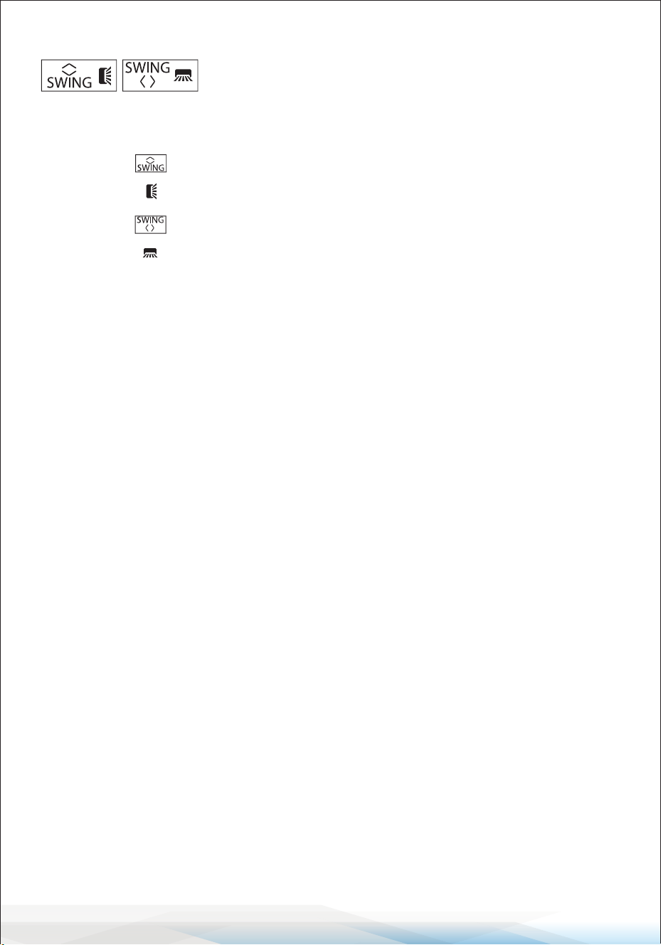
SWING Function
The SWING function adjusts the airow direction by
controlling the louvers.
1. Horizontal Swing (Up/Down):
• Press the button to activate the horizontal aps, which swing up and
down. The symbol will appear on the remote display.
• Press the button again to stop the swing movement at the current
angle. The symbol will appear on the remote display.
2. Vertical Swing (Left/Right):
• Press the SWING button again to activate the vertical deectors, which
swing left and right.
• The corresponding symbol will appear on the remote display.
• Press the SWING button again to stop the swing movement at the current
angle.
3. Manual Adjustment of Vertical Deectors:
If the vertical deectors are positioned manually (under the horizontal aps),
they can direct airow to the left or right as needed.
4. Self-Clean Function (for Inverter Heating Models):
Press the Horizontal SWING and Vertical SWING buttons simultaneously while
the appliance is turned o to activate the Self-Clean function.
Important:
• Never adjust the horizontal aps manually to avoid damaging the delicate
mechanism.
• Do not insert ngers, sticks, or other objects into the air inlet or outlet vents to
prevent accidental contact with live parts, which could cause serious injury or
damage.
www.SereneLifeHome.com
17
TURBO Function
The TURBO function enables quick cooling or heating by operating
at the highest fan speed to deliver strong airow.
• To activate the TURBO function, press the TURBO button.
The symbol will appear on the display.
• Press the TURBO button again to cancel this function.
Note:
In COOL or HEAT mode, selecting the TURBO function allows the appliance to
quickly cool or heat the room by running at maximum fan speed.
MUTE Function
The MUTE function operates the air conditioner at the lowest fan
speed for a quieter experience.
1. Press the MUTE button to activate this function.
The & symbol will appear on the remote display.
2. Press the MUTE button again to deactivate the function.
3. While the MUTE function is active:
• The remote display will show AUTO fan speed.
• The indoor unit will operate at the lowest fan speed to provide a quiet
environment.
4. Pressing the FAN or TURBO button will automatically cancel the MUTE function.
5. The MUTE function cannot be activated in DRY mode.
SLEEP Function
The SLEEP function enables an automatic pre-set operating program
for comfortable sleep.
• Press the SLEEP button to activate the function.
The symbol will appear on the display.
• Press the SLEEP button again to cancel the function.
• After 10 hours of continuous operation in SLEEP mode, the air conditioner will
automatically switch back to the previously set mode.
www.SereneLifeHome.com
18
I FEEL Function (Optional)
The I FEEL function optimizes the temperature around the remote
control's location.
1. Press the I FEEL button to activate this function.
The symbol will appear on the remote display.
2. Press the I FEEL button again to deactivate the function.
3. When activated, the remote control measures the temperature at its current
location and sends this information to the air conditioner for optimized comfort.
4. The function will automatically deactivate after 8 hours
(or 2 hours for some models).
ECO Function
The ECO function allows the appliance to operate in energy-saving
mode.
1. Press the ECO button to activate the function. The symbol will appear on the
display, and the appliance will run in ECO mode.
2. Press the ECO button again to cancel the function.
Note: The ECO function is available in both COOLING and HEATING modes.
DISPLAY Function (Indoor Display)
The DISPLAY function allows you to switch the LED display on the indoor unit
panel ON or OFF.
1. Press the DISPLAY button to turn o the LED display on the panel.
2. Press the DISPLAY button again to turn the LED display back on.
GEN Function (Optional)
The GEN function adjusts the operating gear to manage power consumption.
1. Turn on the indoor unit. Press and hold the MUTE button for 3 seconds to
activate the GEN function. Repeat to deactivate it.
2. While the GEN function is active:
• Short press the MUTE button to select power levels (L3, L2, L1, or OF).
• Select OF and wait 2 seconds to exit the GEN function.
3. If the indoor unit displays OA, use the remote to raise the operating gear of
the GEN mode. The compressor will restart after stopping for 3 minutes.
www.SereneLifeHome.com
19
SELF-CLEAN Function (Optional)
The SELF-CLEAN function is available on select heating pump inverter models.
It cleans the indoor unit automatically.
1. Turn o the indoor unit.
2. Press the and buttons simultaneously while pointing the remote at
the indoor unit.
3. A beep will sound, and [AC] will appear on the remote display and the indoor
unit's LED display.
Details:
1. The function runs for approximately 30 minutes and will return to the previous
settings once completed.
2. You can press the button to cancel this function during the process.
You will hear two beeps when the function nishes or is canceled.
3. Some noise during the process is normal as plastic materials expand and
contract with temperature changes.
Recommended Usage:
• Run this function every 3 months for optimal performance.
• Operate under the following ambient conditions to avoid safety protections:
• Indoor unit temperature: Below 86°F (30°C)
• Outdoor unit temperature: Between 41°F (5°C) and 86°F (30°C)
8°C (46°F) Heating Function (Optional)
This function automatically maintains room temperatures above 46°F (8°C) to
prevent freezing.
1. Press and hold the ECO button for 3 seconds to activate this function.
[8°C] (or [46°F]) will appear on the remote display.
2. Press and hold the ECO button again to deactivate the function.
Details:
1. The heating mode will activate automatically when the room temperature
falls below 46°F (8°C).
2. The appliance will return to standby mode when the room temperature
reaches 48°F (9°C).
3. If the room temperature is above 64°F (18°C), the function will cancel
automatically.
www.SereneLifeHome.com
20
Gentle Wind Function (Optional)
This function provides a soft, comfortable airow by adjusting the position of
the vertical aps.
1. Turn on the indoor unit and switch to COOL mode.
2. Press and hold the FAN and MUTE buttons together for 3 seconds to activate
this function. will appear on the display.
3. Repeat the same steps to deactivate the function.
Details: The vertical aps will automatically close, providing a gentle wind eect.
Health Function (Optional)
This function activates features such as an ionizer, plasma system, bipolar ionizer,
or UVC lights (depending on the model) for improved air quality.
1. Turn on the indoor unit.
2. Press and hold the SLEEP and DISPLAY buttons together for 3 seconds to
activate this function. will appear on the display.
3. Repeat the same steps to deactivate the function.
Details: When the HEALTH function is active, the corresponding air purication
components will be energized and operate automatically.
I SET Function (Optional)
The I SET function allows you to save and quickly activate your favorite settings
for convenience.
To Save Your Favorite Settings:
1. While in any mode (COOLING, HEATING, FAN, or DRY), press and hold the I SET
button for more than 3 seconds.
2. The [AU] symbol will ash on the remote control display, indicating that your
favorite settings have been saved.
3. Press any button to exit the saving process.
You can update the saved settings by repeating steps 1 and 2.
To Activate Your Favorite Settings:
1. While in any mode (COOLING, HEATING, FAN, or DRY), press the I SET button
once.
2. The appliance will run using your saved favorite settings, and the [AU] symbol
will ash on the remote display.
3. Press the I SET button again or any other button to cancel this function.
www.SereneLifeHome.com
21
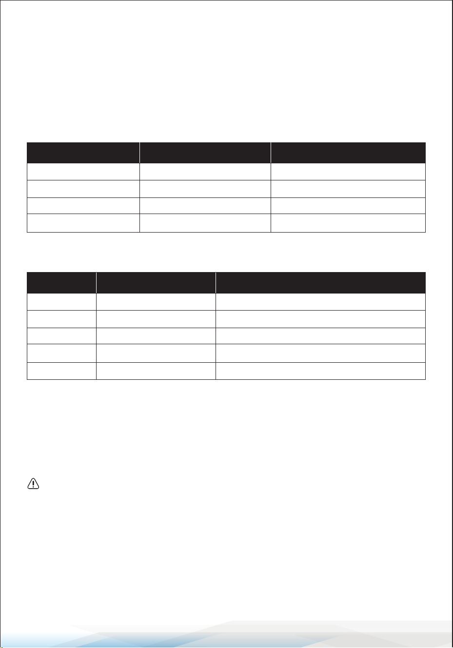
OPERATION INSTRUCTIONS
Using the air conditioner outside of the specied temperature ranges may
activate its protection device and prevent it from functioning properly.
To ensure optimal operation, use the air conditioner within the following
temperature conditions:
Fixed Air Conditioner Temperature Range
Inverter Air Conditioner Temperature Range
Additional Notes:
Restart Delay: When the power supply is connected, restarting the air conditioner
after shutdown or switching to another mode will activate the protection device.
The compressor will resume operation after 3 minutes.
Characteristics of Heating Operation (Applicable to Heat Pump Models):
1. Preheating: When the heating function is enabled, the indoor unit will take
2–5 minutes to preheat before blowing warm air.
2. Defrosting:
• During heating, if the outdoor unit accumulates frost, the air conditioner will
automatically activate the defrosting function to maintain heating eciency.
• While defrosting, the indoor and outdoor fans will stop. The air conditioner
will automatically resume heating after defrosting is complete.
Mode Room Temperature Outdoor Temperature
Cooling 32°F–80°F (0°C–27°C) 19°F–75°F (-7°C–24°C)
Dry 63°F–90°F (17°C–32°C)
T1 Climate 59°F–109°F (15°C–43°C)
T3 Climate 59°F–125°F (15°C–52°C)
Mode Room Temperature Outdoor Temperature
Cooling
32°F–80°F (0°C–27°C) 19°F–75°F (-7°C–24°C) (Low-temp heating)
Dry
63°F–90°F (17°C–32°C)
T1 Climate
T3 Climate
59°F–122°F (15°C–50°C)
59°F–131°F (15°C–55°C)
Heating
63°F–90°F (17°C–32°C)
19°F–122°F (-7°C–50°C) (Low-temp cooling)
www.SereneLifeHome.com
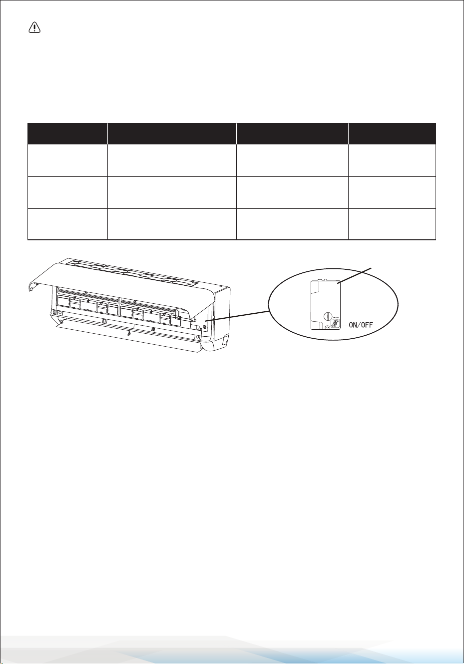
22
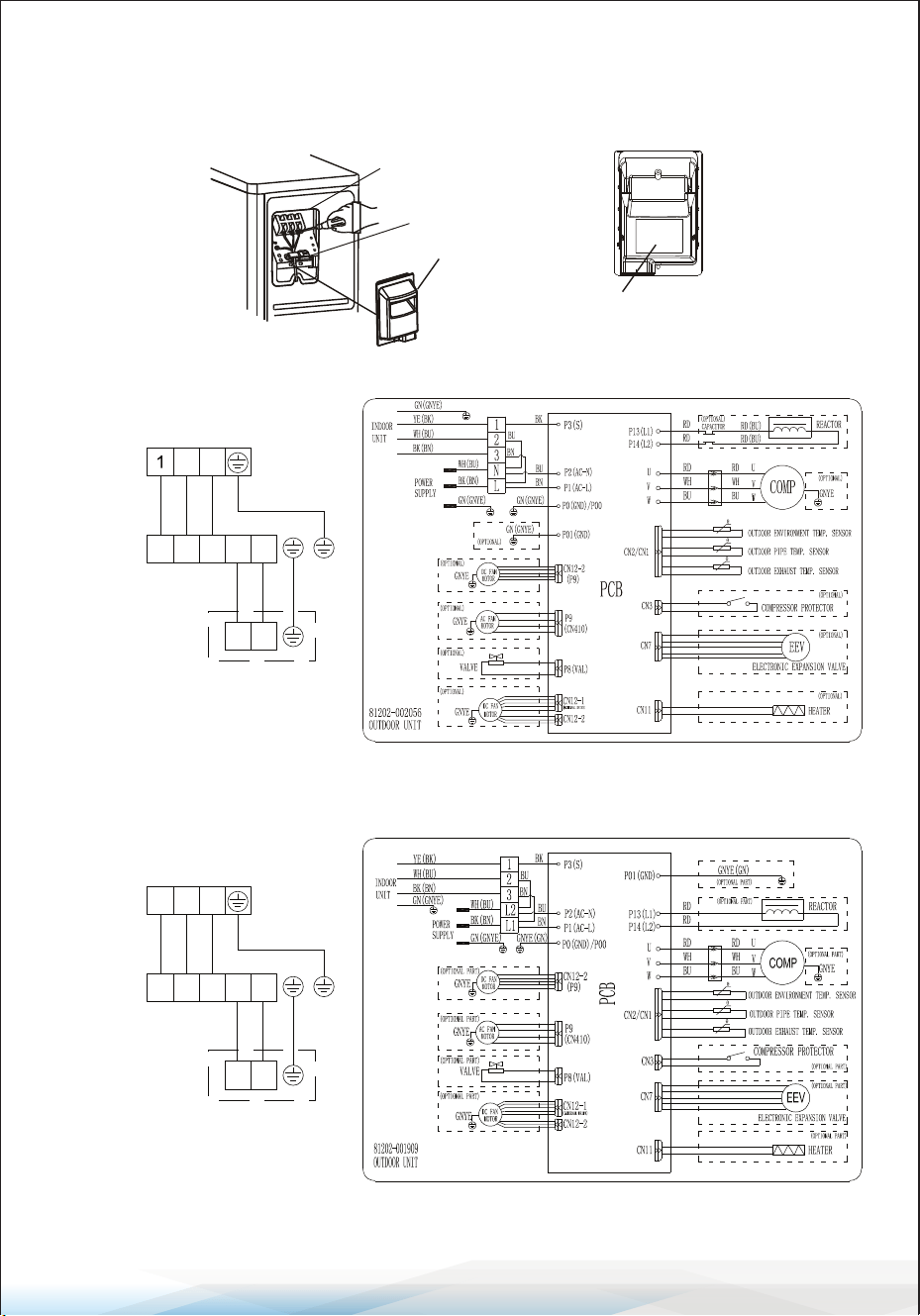
Emergency Button
In case the remote control fails, the Emergency Button can be used to control
the air conditioner.
• Location: Open the panel to access the emergency button on the electronic
control box.
• Important: Always use insulated material to press the emergency button.
Instructions for Servicing (R454B)
1. Refer to this manual to determine the space dimensions required for proper
installation, including the minimum distances from adjacent structures.
2. The appliance must be installed, operated, and stored in a room with a oor
area larger than 43 square feet (4m²).
3. Minimize the length of the pipework during installation.
4. Ensure the pipework is protected from physical damage and avoid installing it
in an unventilated space smaller than 43 square feet (4 m²).
5. Follow national gas regulations during installation.
6. Ensure mechanical connections are accessible for maintenance purposes.
7. Adhere to the instructions in this manual for handling, installing, cleaning,
maintaining, and disposing of refrigerants.
8. Ensure ventilation openings are clear and unobstructed.
9. Notice: Servicing must only be performed as recommended by the manufacturer.
10. Warning: Store the appliance in a well-ventilated area with room size
corresponding to the operational specications.
Current Status
Action Enter Mode
Press and hold the
emergency button once
Cooling mode.
Standby
Response
It beeps briey once.
Press and hold the emergency
button twice within 3 seconds
Heating mode.
Standby
(Heat pump models only)
It beeps briey twice.
Press and hold the
emergency button once
O mode
Running
It keeps beeping
for a while.
(open the panel of indoor unit)
control-box cover
www.SereneLifeHome.com
23
11. Warning: Do not store the appliance in a room with continuously operating
open ames (e.g., gas appliances) or ignition sources (e.g., electric heaters).
12. Prevent mechanical damage to the appliance during storage.
13. Only qualied individuals with valid and up-to-date certication from an
accredited authority should work on refrigerant circuits. Service operations
must align with the manufacturer’s recommendations. Maintenance and
repair requiring assistance from other qualied personnel must be supervised
by a competent person authorized to handle ammable refrigerants.
14. Procedures aecting safety must only be carried out by competent individuals.
15. Important Warnings
• Do not use unauthorized methods to accelerate the defrosting process or
to clean frost. Follow the manufacturer’s guidelines.
• Store the appliance in a room free from continuously operating ignition
sources (e.g., open ames, gas appliances, or electric heaters).
• Do not pierce or burn the appliance.
• Be aware that refrigerants may be odorless.
16. SERVICING INFORMATION
1. Checks to the Area: Before working on systems containing ammable
refrigerants, ensure safety checks are completed to minimize ignition risks.
2. Work Procedures: Work under controlled conditions to minimize the presence
of ammable gases or vapors during repairs.
3. General Work Area: Instruct all maintenance personnel on the nature of the
work. Avoid conned spaces and clearly mark the work area.
Ensure ammable materials are controlled.
4. Refrigerant Detection: Use an appropriate refrigerant detector before and
during work to identify ammable atmospheres. Ensure the detection
equipment is non-sparking and intrinsically safe.
5. Fire Extinguishers: When conducting hot work, have suitable re extinguishing
equipment, such as a dry powder or CO2 extinguisher, near the work area.
6. Ignition Sources: Do not use ignition sources near refrigeration systems,
especially when refrigerant might be released. Display "No Smoking" signs in
the area.
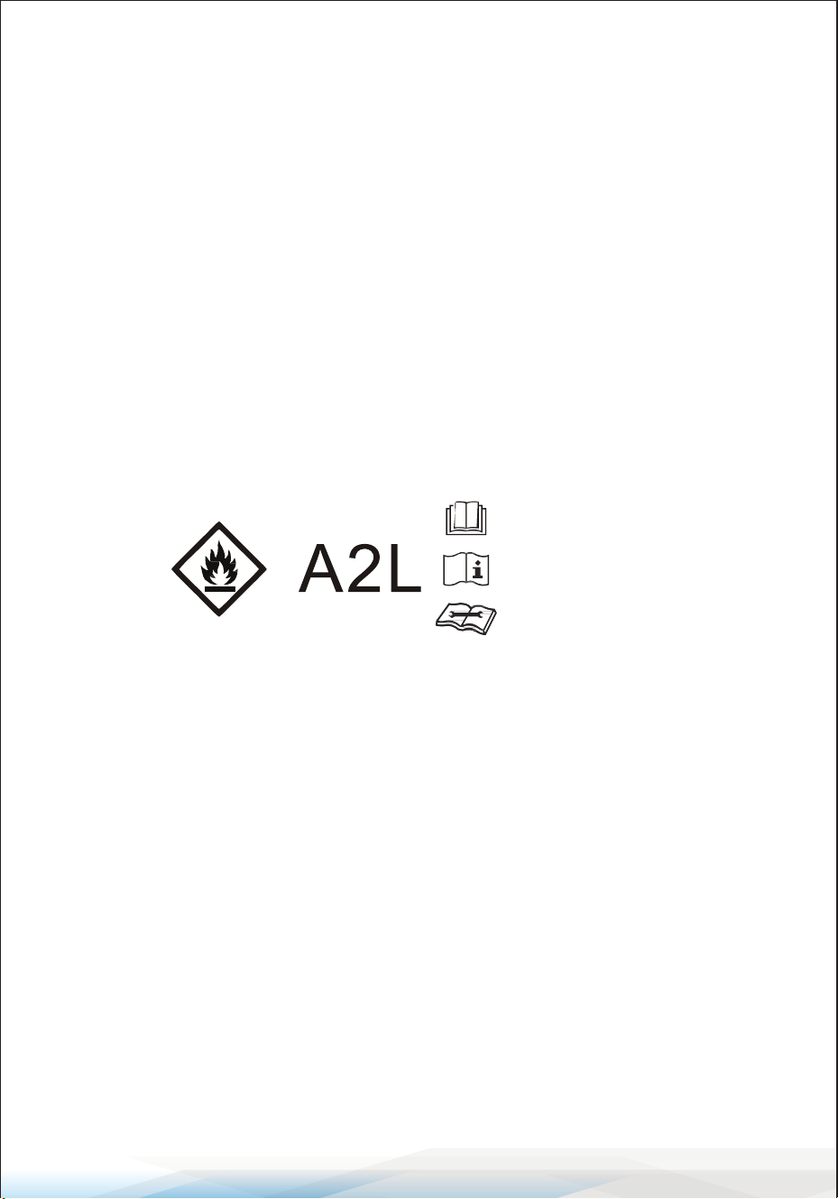
Read operator's manual
Caution: Risk of re
Operating instructions
Read technical manual

www.SereneLifeHome.com
24
7. Ventilation: Ensure adequate ventilation before breaking into the system.
Continue ventilation throughout the work process to safely disperse released
refrigerant.
8. Refrigeration Equipment Checks: Replace electrical components only with
those meeting the manufacturer’s specications. Verify room size and
ventilation requirements match the refrigerant charge. Ensure all labeling
and markings on equipment remain legible.
9. Electrical Device Checks: Perform safety checks, including verifying capacitors
are discharged safely and live electrical components are isolated during
maintenance.
ADDITIONAL NOTES
• Measurements referenced in the manual, such as 2.5 meters (8 feet) for
minimum installation height, have been retained.
• For other instances of "long press," it has been replaced with "press and hold"
for clarity.
• Please conrm if the referenced tables (e.g., Tables GG.1 and GG.2) are included
in the nal document for accuracy.
17. Repairs to Sealed Components
1. Disconnection of Electrical Supplies: Ensure all electrical supplies are
disconnected before removing sealed covers or performing repairs. If electrical
supply is necessary during servicing, employ a permanently operating leak
detection system at the critical point to warn of hazardous situations.
2. Maintaining Protection Levels: Take precautions to avoid altering the casing
or aecting the level of protection when working on electrical components.
This includes:
• Avoiding damage to cables or seals.
• Ensuring terminals and connections meet original specications.
• Properly tting glands and securing apparatus.
• Using replacement parts according to the manufacturer’s specications.
Note: Silicone sealants may impair the eectiveness of certain leak detection
equipment. Intrinsically safe components do not require isolation before
servicing.

www.SereneLifeHome.com
25
18. Repairs to Intrinsically Safe Components
1. Avoid applying permanent inductive or capacitive loads to the circuit
unless veried to be within permissible voltage and current limits.
2. Only intrinsically safe components can be worked on live in ammable
atmospheres. Ensure:
• Test apparatus has the correct rating.
• Replacement parts meet the manufacturer’s specications to prevent
ignition risks.
19. Cabling: Inspect cabling for vulnerabilities, including:
• Wear, corrosion, excessive pressure, or vibration.
• Sharp edges or adverse environmental eects.
• Aging or ongoing vibrations from compressors or fans.
20. Detection of Flammable Refrigerants: Prohibited Practices:
Do not use potential ignition sources, such as halide torches or naked ames,
for refrigerant leak detection.
21. Leak Detection Methods: Acceptable methods for detecting leaks in
systems with ammable refrigerants include:
1. Electronic Leak Detectors:
• Ensure sensitivity and calibration in refrigerant-free areas.
• Use detectors that are non-ignitable and compatible with the refrigerant.
• Set equipment to detect 25% maximum of the Lower Flammability Limit
(LFL) of the refrigerant.
2. Leak Detection Fluids: Use uids suitable for refrigerants, avoiding
chlorine-based detergents.
3. In Case of Leaks:
• Extinguish naked ames.
• Recover refrigerant or isolate the aected system before brazing.
• Purge the system with oxygen-free nitrogen (OFN) before and during
brazing.
22. Removal and Evacuation: Follow these steps when breaking into the
refrigerant circuit for repairs or other purposes:
1. Refrigerant Removal:
• Recover refrigerant into appropriate recovery cylinders.
• Purge the circuit with inert gas.
2. Evacuation:
• Pull a vacuum, purge again with inert gas, and repeat as needed.
• Flush the system with OFN to ensure safety.

www.SereneLifeHome.com
26
3. Brazing Operations:
• Ensure the system is purged with OFN before and during brazing.
• Position vacuum pump outlets away from ignition sources and ensure
ventilation.
23. Decommissioning: Before decommissioning, technicians must:
1. Preparation:
• Familiarize themselves with the equipment.
• Electrically isolate the system.
• Ensure necessary tools, personal protective equipment, and mechanical
handling equipment are available.
2. Recovery Process:
• Supervise recovery operations.
• Follow manufacturer’s instructions for recovery machines.
• Monitor cylinder weight to prevent overlling (maximum 80% liquid
charge).
• Avoid exceeding the cylinder’s maximum working pressure.
3. Post-Recovery:
• Remove cylinders and equipment promptly.
• Close all isolation valves.
• Do not reuse recovered refrigerant unless cleaned and checked.
Adhering to these guidelines ensures safety and compliance during
maintenance and repair operations.
24. Labeling:
1. Label equipment to indicate it has been decommissioned and emptied of
refrigerant.
2. Include a dated and signed label.
3. Ensure the label species that the equipment contains ammable
refrigerant.
25. Recovery:
When removing refrigerant for maintenance or decommissioning, ensure it is
done safely. Use only proper recovery cylinders, ensuring there are enough
to hold the entire system's charge. Cylinders must be labeled for refrigerant
recovery, equipped with a pressure-relief valve, and in good condition.
Empty cylinders should be evacuated and cooled before use.
Recovery equipment must be in good condition, have clear instructions, and
be suitable for all refrigerants, including ammable types. Use calibrated
weighing scales and leak-free hoses.

www.SereneLifeHome.com
27
Before using recovery machines, verify they are functioning correctly, properly
maintained, and safe from ignition risks. Consult the manufacturer if needed.
Recovered refrigerant should be returned to the supplier in the correct
cylinder. Never mix refrigerants. For compressors or oils, evacuate them fully
to remove any ammable refrigerants. Use only electric heating to speed up
this process. When draining oil, do it safely.
INSTALLATION PRECAUTIONS
Important Considerations Summary:
1. Only professionals should install the air conditioner, following the installation
manual and our after-sales service regulations.
2. Handling combustible refrigerants improperly can cause serious injuries or
damage.
3. Perform a leak test after installation.
4. Always conduct a safety inspection before maintaining or repairing air
conditioners with combustible refrigerants to minimize re risk.
5. Follow proper procedures during operation to reduce risks from combustible
gases or vapors.
6. Ensure the total refrigerant weight and room area meet the requirements
shown in Tables GG.1 and GG.2.
Maximum Refrigerant Charge and Minimum Floor Area Requirements
1. Maximum Refrigerant Charge:
The maximum refrigerant charge depends on the room size and the
refrigerant’s ammability limit (LFL):
• For R454B, the LFL is 0.301 kg/m³.
• Example formulas for room sizes:
• m = (6m³) x LFL
• m = (52m³) x LFL
• m = (260m³) x LFL
2. Maximum Charge in a Room:
For appliances with a refrigerant charge less than M:
Where:
• m: Maximum charge (kg)
• h: Height of installation (m)
• A: Floor area (m²)
www.SereneLifeHome.com
28
3. Minimum Floor Area Requirement: The minimum oor area required for an
appliance with a charge amount M is calculated as:
Minimum Floor Area for R454B Refrigerant
Charge (kg) Height (m) Minimum Floor Area (m²)
1.0 1.0 13.29
1.2 1.0 15.95
1.4 1.0 18.60
1.6 1.0 21.26
1.8 1.0 23.92
2.0 1.0 26.58
2.2 1.0 29.24
1.0 1.8 7.38
1.2 1.8 8.86
1.4 1.8 10.34
1.6 1.8 11.81
1.8 1.8 13.29
2.0 1.8 14.77
2.2 1.8 16.24
1.0 2.2 6.04
1.2 2.2 7.25
1.4 2.2 8.46
1.6 2.2 9.66
1.8 2.2 10.87
2.0 2.2 12.08
2.2 2.2 13.29
M

www.SereneLifeHome.com
29
Installation Safety Principles
1. Site Safety
• Open Flames Prohibited: Keep the area free from open ames.
• Ventilation Necessary: Ensure the area is well-ventilated.
2. Operation Safety
Mind Static Electricity:
• Wear protective clothing and anti-static gloves.
• Avoid using mobile phones near the installation area to prevent static buildup.
3. Installation Safety
• Refrigerant Leak Detector: Use a refrigerant leak detector during installation
to monitor for any leaks.
• Appropriate Installation Location: Choose a safe location for the air
conditioner.
Important Installation Notes:
1. The installation site must be well-ventilated.
2. The site must be free from open ames, welding, smoking, drying ovens, or
any other heat sources above 548°C that could easily cause a re.
3. When installing, always take anti-static precautions, such as wearing anti-
static clothing or gloves.
4. The installation site should allow easy access for maintenance and should not
be near heat sources, combustible materials, or hazardous environments.
5. If a refrigerant leak occurs during installation:
• Immediately turn o the valve of the outdoor unit.
• All personnel must leave the area until the refrigerant has completely leaked
out (approximately 15 minutes).
• If the product is damaged, take it to the maintenance station for repair.
Do not attempt to weld the refrigerant pipe or perform any other repairs at
the installation site.
6. Choose a location where the air inlets and outlets of the indoor unit are
unobstructed.
7. Avoid placing electrical products, power switches, plugs, kitchen cabinets,
beds, sofas, or other valuables directly under the indoor unit’s air inlets and
outlets.

www.SereneLifeHome.com
30
Suggested Tools
• Standard Wrench
• Pipe Cutter
• Vacuum Pump
• Adjustable/Crescent Wrench
• Screwdrivers (Phillips & Flat blade)
• Safety Glasses
• Torque Wrench
• Manifold and Gauges
• Work Gloves
Pipe Length, Additional Refrigerant, and Torque Parameters Summary
Pipe Length and Additional Refrigerant (Inverter Models):
1. Pipe Length with Standard Charge:
• Global Models: 5m (16ft) for all capacities.
• North American Models: 7.5m (24ft) for all capacities.
2. Maximum Distance Between Indoor and Outdoor Units:
• 9K-12K BTU/h: 15m (49ft).
• 18K-24K BTU/h: 20m (65ft).
• 30K-36K BTU/h: 30m (98ft).
3. Additional Refrigerant Charge:
• R22/R410A: 20g/m for 9K-12K BTU, 30g/m for 18K-36K BTU.
• R454B: 10g/m for all capacities.
4. Maximum Height Dierence Between Indoor and Outdoor Units:
• 9K-12K BTU: 10m (32ft).
• 18K-24K BTU: 15m (48ft).
• 30K-36K BTU: 20m (65ft).
5. Refrigerant Types: Compatible with R22, R410A, and R454B.
Torque Parameters for Pipe Sizes:
• 1/4" (6.35mm): 15-20 Nm | 11.1-14.8 lb-ft | 1.5-2.0 kgf-m.
• 3/8" (9.52mm): 31-35 Nm | 22.9-25.8 lb-ft | 3.2-3.6 kgf-m.
• 1/2" (12mm): 45-50 Nm | 33.2-36.9 lb-ft | 4.6-5.1 kgf-m.
• 5/8" (15.88mm): 60-65 Nm | 44.3-48.0 lb-ft | 6.1-6.6 kgf-m.
Note: Always comply with local laws and regulations for installation requirements.
• Hex Keys or Allen Wrenches
• Level
• Refrigerant Scale
• Drill & Drill Bits
• Flaring Tool
• Micron Gauge
• Hole Saw
• Clamp-on Amp Meter
www.SereneLifeHome.com
31
Indoor Unit Installation
Step 1: Select Installation Location
1. Compliance: Ensure the installation meets the specied minimum dimensions,
piping length, and elevation requirements in the System Requirements section.
2. Airow: Keep the air inlet and outlet free of obstructions for proper room
ventilation.
3. Condensate Drainage: Ensure safe and easy drainage of condensate.
4. Connections: Position the unit where it can connect easily to the outdoor unit.
5. Safety: Install the unit out of children’s reach.
6. Sturdy Mounting: Use a wall that can support four times the unit's weight
and handle its vibrations.
7. Filter Access: Ensure easy access to the lter for cleaning.
8. Maintenance Space: Leave enough space for routine maintenance access.
9. Interference Avoidance: Install at least 10 ft. (3 m) away from TV or radio
antennas to prevent interference. Weak reception areas may need an amplier.
10. Environment: Avoid installing the unit in corrosive areas like laundry rooms
or near swimming pools.
11. ETL Certication Requirement: For certied areas, ensure the lowest moving
parts are at least 8 ft. (2.4 m) above the oor or grade level.
Minimum Indoor Clearances
Ceiling
20cm / 8 in.
13cm / 5 in. 13cm / 5 in.
250cm / 8� .
F
lo
or
www.SereneLifeHome.com
32
Step 2: Install the Mounting Plate
1. Remove the Mounting Plate: Detach the mounting plate from the back of
the indoor unit.
2. Position the Plate: Ensure it meets the minimum installation dimensions.
Align the plate to the wall based on its size.
3. Level the Plate: Use a spirit level to ensure the plate is horizontal.
Mark the screw hole positions on the wall.
4. Drill Holes: Take down the plate and drill holes at the marked positions.
5. Insert Plugs and Secure Plate: Insert expansion plugs into the holes, hang
the plate, and secure it with screws.
Notes:
• Ensure the mounting plate is rmly installed and at against the wall.
• Actual components may dier from the illustration; refer to the actual object.
Step 3: Drill the Wall Hole
1. Determine Hole Location: Decide where to drill the hole based on the
position of the mounting plate.
2. Hole Specications: The hole should be at least 70mm in diameter and
drilled at a slight angle to allow for proper drainage.
3. Drill the Hole: Use a 70mm core drill and ensure the hole slopes slightly
downward by 5-10mm from the indoor end.
4. Protect the Connection Parts: Install a wall sleeve and sleeve cover
(if available) to safeguard the connection.
Caution:
When drilling, avoid hitting wires, plumbing, or other sensitive components.
70mm
Wall sleeve
(Op�onal)
5-10mm
Wall sleeve Cover
(Op�onal)
Outdoor
Indoor
Small bolique angle
2.8 (70mm)
www.SereneLifeHome.com
33
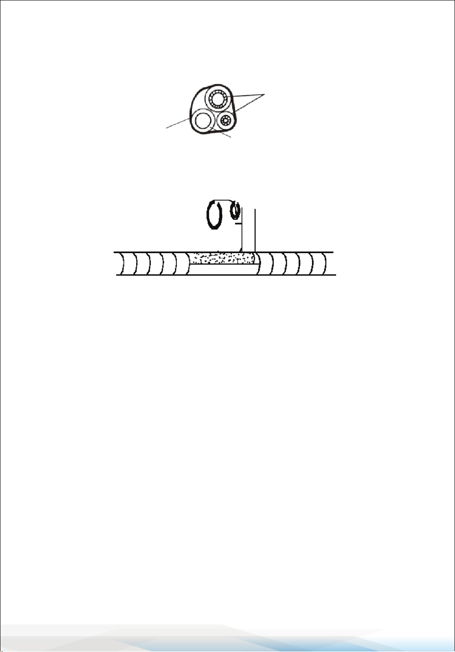
Step 4: Connecting the Refrigerant Pipe
1. Choose Piping Mode:
• Select the appropriate piping mode (Mode 1, 2, or 3) based on the wall hole
position.
• For Mode 1 or 3, cut and smooth the plastic sheet at the piping and cable
outlet on the indoor unit using scissors.
2. Bend the Connecting Pipes: Bend the pipes carefully, ensuring the pipe
ports face upward. Refer to the diagram for proper bending. Avoid sharp or
improper bends.
3. Prepare the Pipe Ports:
• Remove the plastic cover from the pipe ports and the protective cover from
the pipe connectors.
• Check that the pipe port is clean and free of debris.
4. Connect the Pipes:
• Align the pipe port center and hand-tighten the nut of the connecting pipe.
• Use a torque wrench to tighten the nut according to the Torque Requirements
Table in the Installation Precautions section.
5. Insulate the Joint: Wrap the joint securely with insulation pipe to maintain
eciency and prevent condensation.
Note:
If reusing ared joints indoors,
re-fabricate the are part to
ensure proper sealing.
3
2
1
Piping outlet
Cable outlet
NO
YES
The connector should be outdoor
OutdoorIndoor
www.SereneLifeHome.com
34
Step 5: Connect the Drainage Hose
1. Adjust the Drainage Hose (if applicable)
• Some models have drainage ports on both sides of the indoor unit.
Choose one drainage port to connect the drainage hose.
• Use the provided rubber stopper to seal the unused drainage port.
2. Connect the Drainage Hose: Attach the drainage hose rmly to the selected
drainage port. Ensure the connection is tight and properly sealed.
3. Wrap the Joint with Teon Tape: Wrap the connection point with Teon tape
to prevent leaks.
Note:
• Ensure the hose is free of twists, dents, or blockages.
• Position the drainage hose at a downward slope to allow for proper drainage.
P TC -L
P TC -N
HE ATE R (O PTI ONAL)
C N16
C N8
DIS P LAY
C N5-1
M
S WIN G MO TO R
C N5-2
S WIN G MO TO R
(O P TION AL)
INDOOR WIRING DIAGRAM
EV AP OR AT OR
P 0
WIF I(O P TI ONAL)
P C B
C N6
R T
IP T
R OO M T E MP E R ATU R E
TU BE T E MP E R ATU R E
P 1( P 1L )(AC -L)
OUT-L
K 1
G NY E( G N)
C N14
P E OP LE F E E L
C N19
HUMID ITY S E NS OR
(O P TION AL)
(O P TION AL)
C N5-3
S WIN G MO TO R
(O P TION AL)
M
M
81102
-
040197
B N(R D)
B U
B K
1
2
3
P 2( N)( AC -N)
G NYE
P S (S /SIG )
C N27
G E NE R ATO R
(O P TION AL)
UV L IG HT
(O P TION AL)
CN 3
M
DC F AN MOT OR
CN 3
CN 4
M
(O P TION AL)
AC F AN MOT OR
C N11
G E NE R ATO R
(O P TION AL)
G NYE
C N1
C N2
(O P TION AL)
TR ANS FO R ME R
(F LZ )
C N5-4
S WIN G MO TO R
(O P TION AL)
M
C N9
AU DIO (O P TI ONAL)
C N14B
IN FR AR E D S E NS E
TX
RX
(O P TION AL)
OUT DOOR
UNIT
(O P TION AL)
(O P TION AL)
WH
Y E (R D)
B K
G N
B N
(O P TION AL)
9-18K (Wiring diagram)
Drainage ports
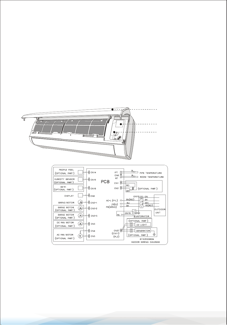
Step 6: Connect Wiring
1. Select the Correct Cable Size:
Choose cables based on the
maximum operating current
specied on the unit's nameplate.
Refer to the INSTALLATION
PRECAUTIONS section for details.
2. Open the Indoor Unit Panel:
Open the front panel of the
indoor unit.
www.SereneLifeHome.com
35
3. Access the Control Box: Use a screwdriver to remove the cover of the electric
control box, exposing the terminal block.
4. Unscrew the Cable Clamp: Loosen the cable clamp to prepare for wiring.
5. Insert the Cable: Insert one end of the cable into the control box through the
back of the indoor unit.
6. Connect the Wires: Connect each wire to its corresponding terminal according
to the wiring diagram on the electric control box cover. Ensure all connections
are secure.
7. Secure the Cable: Tighten the cable clamp to fasten the cables in place.
8. Reinstall Covers: Replace the electric control box cover and the indoor unit's
front panel.
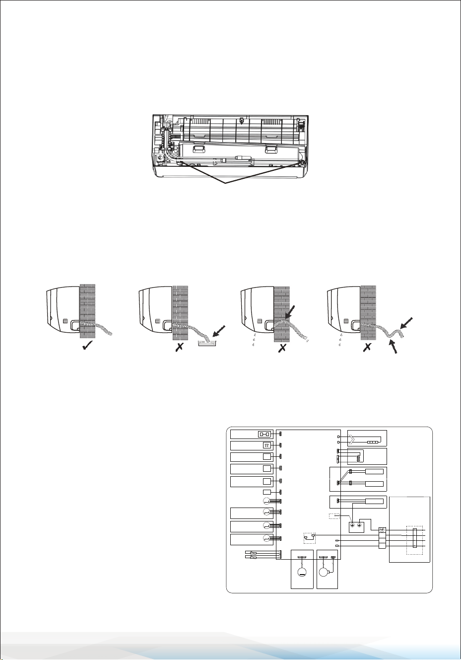
Step 7: Wrap Piping and Cable
After installing the refrigerant pipes, connecting wires, and drainage hose,
bundle them with insulating tape to save space, protect them, and ensure
proper insulation before passing them through the wall hole.
1. Arrange the Components
• Arrange the pipes, cables, and drainage hose as shown in the diagram.
Front panel
Wiring diagram
Control box cover
www.SereneLifeHome.com
36
• Note:
1. Ensure the drainage hose is positioned at the bottom.
2. Avoid crossing or bending the parts to maintain proper alignment.
2. Wrap with Insulating Tape: Use insulating tape to wrap the refrigerant pipes,
connecting wires, and drainage hose tightly into one bundle.
Step 8: Mount the Indoor Unit
1. Feed the Bundle Through the Wall Hole: Carefully pass the wrapped bundle
(pipes, wires, and drainage hose) through the wall hole.
2. Hook the Indoor Unit: Hang the top of the indoor unit on the mounting plate.
3. Secure the Indoor Unit: Apply gentle pressure to the left and right sides to
ensure the unit is rmly hooked onto the mounting plate.
4. Snap the Bottom Into Place: Press down on the bottom of the indoor unit to
engage the hooks on the mounting plate. Ensure it is securely in place.
Alternate Installation Instructions
If refrigerant pipes are already embedded in the wall, or if you want to
connect the pipes and wires on the wall, follow these steps:
1. Hook the top of the indoor unit onto the mounting plate without the piping
and wiring.
2.Tilt the indoor unit away from the wall and unfold the bracket on the mounting
plate to create a larger working space.
3. Complete the piping, wiring, and drainage hose connection as described in
Steps 4 to 7.
Refrigerant piping
Drainage hose
Insulation tape
www.SereneLifeHome.com
37
Outdoor Unit Installation
Step 1: Select Installation Location
Choose a site that meets these conditions:
1. Avoid Heat Sources and Flammable Areas: Do not install the unit near
sources of heat, steam, or ammable gas.
2. No Excessive Wind or Dust: Avoid areas that are too windy or dusty.
3. Minimize Noise Disturbance: Avoid locations near frequently traveled areas
or neighbors who may be disturbed by operating noise or discharged air.
4. Shade from Direct Sunlight: Install in a shaded area or use protective covers
if exposed to direct sunlight (ensure it doesn’t block airow).
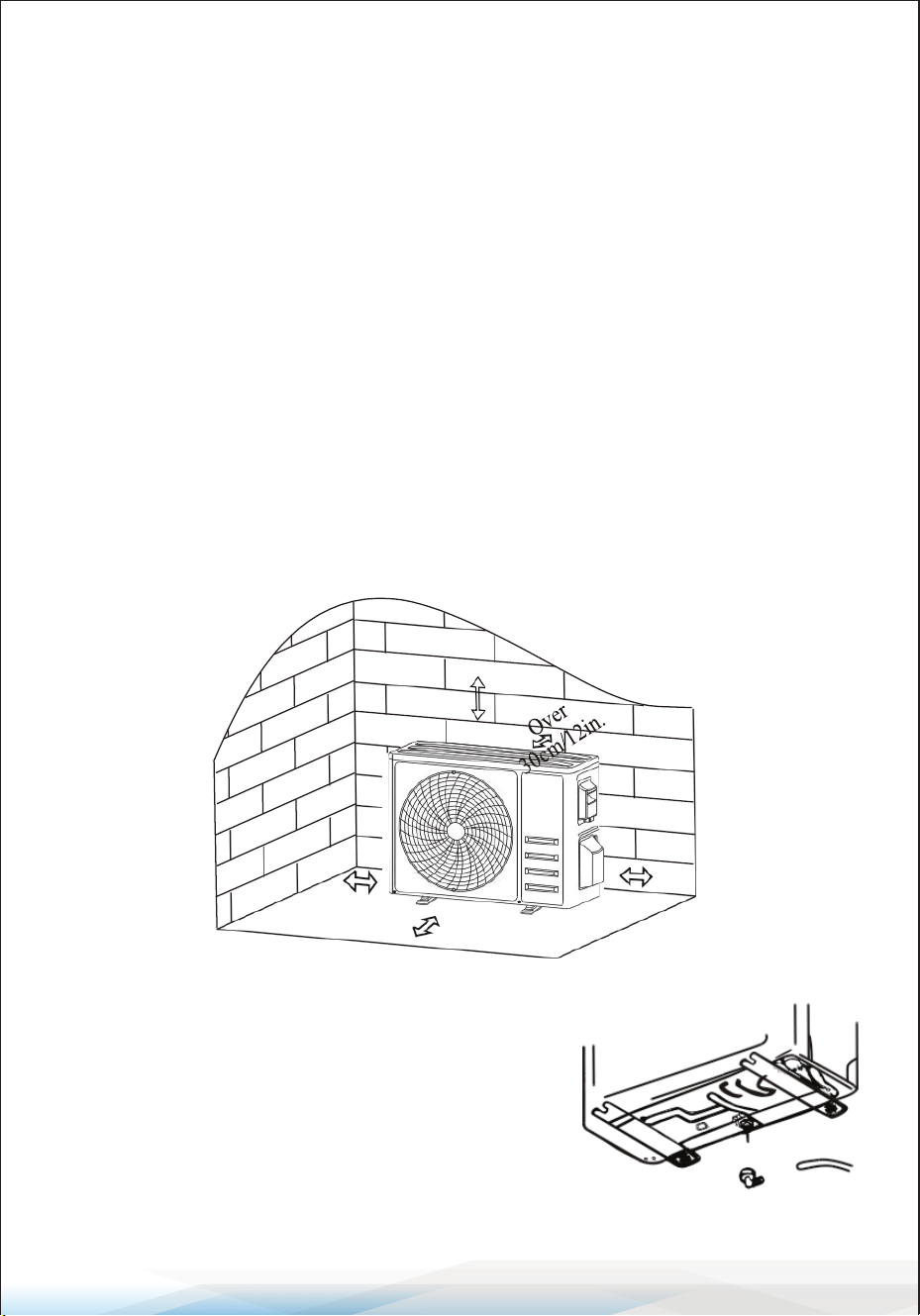
5. Provide Adequate Clearance: Leave enough space around the unit as shown
in the diagram to ensure proper airow.
6. Install on Stable Ground: Mount the unit on a sturdy and secure surface.
7. Vibration Dampening: Place rubber blankets under the feet of the unit to
reduce vibrations and noise (if necessary).
Step 2: Install Drainage Hose (For Heat Pump Models or RCACs)
1. Attach the Drainage Joint:
Insert the drainage joint into the hole at the
bottom of the outdoor unit.
2. Connect the Drainage Hose:
Securely connect the drainage hose to the joint.
Over
50cm/20in.
Over
30cm/12in.
Over
50cm/20in.
Over 200cm/79in.
Drainage joint Drainage hose
www.SereneLifeHome.com
38
Step 3: Fix the Outdoor Unit
1. Mark Bolt Positions: Use the outdoor unit’s dimensions to mark positions for
the expansion bolts.
2. Drill and Clean Holes: Drill holes in the mounting surface, clean out concrete
dust, and insert the expansion bolts.
3. Install Rubber Blankets (Optional): Place rubber blankets on the mounting
surface (if applicable) to reduce vibrations.
4. Mount the Outdoor Unit: Position the outdoor unit base over the bolts and
pre-drilled holes.
5. Secure with Wrench: Tighten the bolts rmly using a wrench to ensure the
unit is stable.
Additional Note
If mounting on a wall, use a wall-mounting bracket.
1. Follow the bracket instructions to secure it to the wall.
2. Ensure the bracket can support at least 4 times the weight of the outdoor unit.
3. Once secured, fasten the outdoor unit to the bracket and keep it horizontal.
Step 4: Install Wiring
1. Remove the Wiring Cover
• Use a Phillips screwdriver to unscrew the wiring cover.
• Gently press and remove the cover.
2. Detach the Cable Clamp: Unscrew the cable clamp and remove it.
3. Connect Wires
• Refer to the wiring diagram located inside the wiring cover.
• Connect the wires to the corresponding terminals securely and rmly.
4. Reinstall the Cable Clamp and Wiring Cover
• Fasten the cable clamp back into place.
• Reattach the wiring cover and secure it tightly.
Install 4 rubber blankets (Optional)
www.SereneLifeHome.com
39
Note:
Always cut o the power supply when connecting the indoor and outdoor unit
wires to avoid electrical hazards.
1 2
3
N L
N L
2
3
INDOOR UNIT
OUTDOOR
UNIT
WALL
POWER SUPPLY
ONLY 115V
1 2
3
L2 L1
L2 L1
1 2
3
INDOOR UNIT
OUTDOOR
UNIT
WALL
POWER SUPPLY
ONLY 208/230V
Terminal block
Cable clamp
Wiring cover
Wiring diagram
9-12K(115V)Wiring diagram
18-36K(115V) / 9K-36K(230V) Wiring diagram
www.SereneLifeHome.com
40
Fuse Ratings for Indoor and Outdoor Units
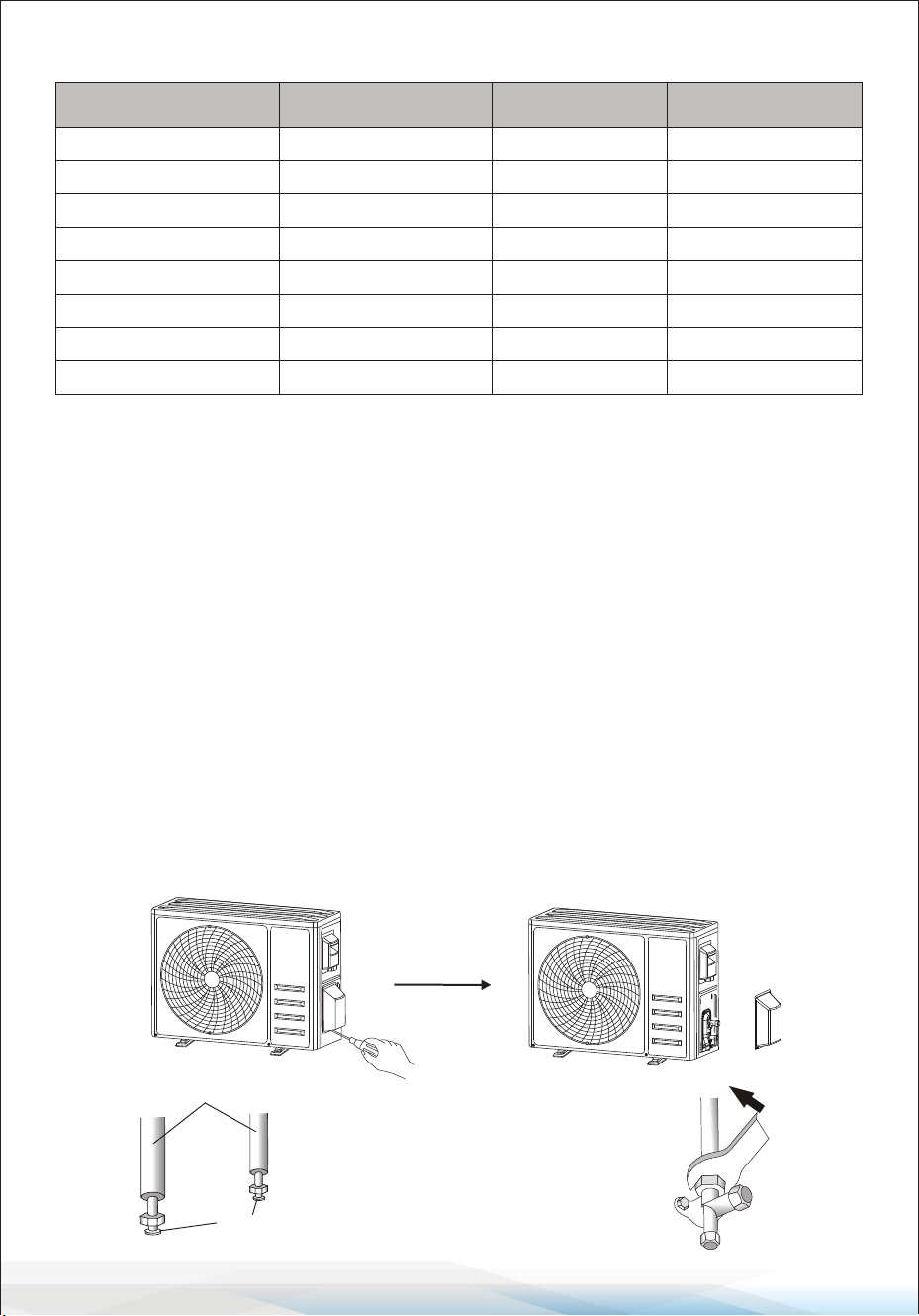
Step 5: Connecting Refrigerant Pipe
1. Unscrew the Valve Cover: If applicable, gently unscrew and press the valve
cover to remove it.
2. Remove Protective Caps: Take o the protective caps from the valve ends.
3. Inspect the Pipe Ports:
• Remove the plastic cover from the pipe ports.
• Ensure the ports are clean and free from debris.
4. Align and Tighten the Flare Nut
• Align the center of the connecting pipe to the valve.
• Rotate the are nut by hand to tighten it as much as possible.
5. Tighten with Tools
• Use a spanner to hold the valve body steady.
• Tighten the are nut using a torque wrench according to the specied
torque values.
(Refer to the Torque Requirements Table in the Installation Precautions section.)
Unit Unit
Fuse type and ra�ng Fuse type and ra�ng
9K-230V indoor unit
9K-230V outdoor unit
9K-115V indoor unit
9K-115V outdoor unit
12K-230V indoor unit
12K-230V outdoor unit
12K-115V indoor unit
12K-115V outdoor unit
18K indoor unit
18K outdoor unit
24K indoor unit
24K outdoor unit
24K outdoor unit
36K indoor unit
36K outdoor unit
36K outdoor unit
4A 250V
15A/250V
4A 250V
25A/250V
4A 250V
15A/250V
4A 250V
25A/250V 3.15A/250VAC
30A/250V
4A 250V
3.15A/250VAC
30A/250V
4A 250V
4A 250V
25A/250V
connection pipes
flare nuts
Take down the valve cover

www.SereneLifeHome.com
41
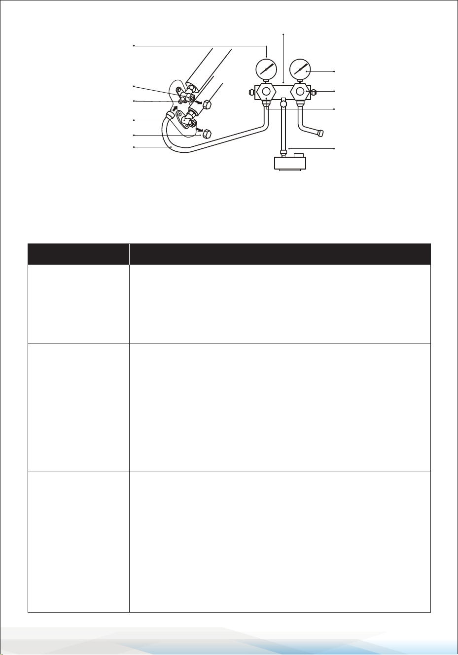
Step 6: Vacuum Pumping
1. Remove Protective Caps: Use a spanner to remove the protective caps from
the service port, low-pressure valve, and high-pressure valve on the outdoor
unit.
2. Connect Manifold Gauge and Vacuum Pump:
• Attach the pressure hose of the manifold gauge to the service port on the
outdoor unit's low-pressure valve.
• Connect the charge hose from the manifold gauge to the vacuum pump.
3. Adjust the Manifold Gauge
• Open the low-pressure valve on the manifold gauge.
• Ensure the high-pressure valve is closed.
4. Turn on the Vacuum Pump
• Start the vacuum pump to evacuate the system.
• Allow the vacuum to run for at least 15 minutes, or ensure the compound
gauge reads -0.1 MPa (-76 cmHg).
5. Stop the Vacuum Process
• Close the low-pressure valve on the manifold gauge.
• Turn o the vacuum pump.
6. Check for Pressure Stability
• Hold the system pressure for 5 minutes.
• Verify that the compound gauge pointer does not rebound more than 0.005
MPa.
7. Add Initial Refrigerant
• Using a hexagonal wrench, open the low-pressure valve counterclockwise
for 1/4 turn to allow a small amount of refrigerant to enter the system.
• Close the low-pressure valve after 5 seconds and quickly remove the
pressure hose.
8. Check for Leaks: Inspect all indoor and outdoor connections using soapy
water or a leak detector.
9. Fully Open Valves: Open both the low-pressure and high-pressure valves on
the outdoor unit fully using a hexagonal wrench.
10. Reinstall Protective Caps: Replace the protective caps on the service port,
low-pressure valve, and high-pressure valve.
11. Reinstall the Valve Cover: Ensure the valve cover is securely reinstalled to
protect the connections.
www.SereneLifeHome.com
42
Test Operation
Inspections Before Test Run
Perform the following checks to ensure safety and proper functionality before
starting the air conditioner:
compound gauge
Low pressure valve
Valve protec�ve caps
Pressure hose
Pressure gauge
High pressure valve
Charge hose
High pressure valve
Low pressure valve
Vacuum pump
Service port
Manifold gauge
Description Inspection Method
Electrical Safety
Inspection
• Verify that the power supply voltage meets the required
specication.
• Check for any incorrect or missing connections between
power lines, signal lines, and earth wires.
• Ensure the earth resistance and insulation resistance comply
with the requirements.
Installation Safety
Inspection
• Conrm that the drainage pipe is installed in the correct
direction and is unobstructed.
• Ensure the refrigerant pipe joints are properly installed and
secure.
• Verify the stability and safety of the outdoor unit, mounting
plate, and indoor unit installation.
• Conrm that the valves are fully open.
• Ensure no foreign objects or tools are left inside the unit.
• Conrm the complete installation of the indoor unit's air inlet
grille and panel.
Refrigerant
Leakage
Detection
• Inspect piping joints, valve connectors on the outdoor unit,
valve spools, welding ports, and other potential leakage areas.
Foam Detection Method: Apply soapy water to potential
leakage points. If no bubbles form, the connection is safe.
Leak Detector Method: Use a professional leak detector per its
instructions to check for leaks.
• Inspect each point for at least 3 minutes.
• If leakage is detected, tighten the nut and retest until no
leakage is found.
• Wrap exposed pipe connectors with thermal insulation
material and insulation tape after testing.

www.SereneLifeHome.com
43
Test Run Instructions
1. Turn on the power supply.
2. Press the ON/OFF button on the remote controller to start the air conditioner.
3. Press the Mode button to switch between COOLING and HEATING modes.
For each mode, set the following:
• COOLING: Set the temperature to the lowest setting.
• HEATING: Set the temperature to the highest setting.
4. Run the air conditioner in each mode for approximately 8 minutes, ensuring
all functions respond properly. Check the following:
• Outlet Air Temperature: Ensure the air temperature responds to both
COOLING and HEATING modes.
• Drainage: Conrm water drains properly from the drainage hose.
• Louver and Deectors: Verify that they rotate properly (if applicable).
5. Observe the air conditioner's performance for at least 30 minutes during the
test run.
6. After a successful test, return the settings to normal and press the ON/OFF
button to turn o the unit.
7. Provide the following information to the user:
• Instruct the user to read this manual carefully before using the air conditioner.
• Demonstrate proper operation, service, and maintenance procedures.
• Remind the user to store accessories safely.
Note: If the ambient temperature exceeds the operational range specied in the
Operation Instructions section and the COOLING or HEATING mode cannot run,
lift the front panel and use the emergency button to activate these modes.
Maintenance
WARNING:
• Before cleaning, turn o the air conditioner and disconnect the power supply
for at least 5 minutes.
• Never ush the air conditioner with water.
• Do not use volatile liquids (e.g., thinner or gasoline) for cleaning, as these can
damage the unit. Instead, use a soft dry cloth or a damp cloth with neutral
detergent.
• Regularly clean the lter screen to prevent dust buildup, which can reduce
ltering eciency. If the environment is dusty, increase the cleaning frequency.
• After removing the lter screen, avoid touching the ns of the indoor unit to
prevent injury.
44
Cleaning the Unit
1. Use a soft cloth dampened with water or neutral detergent.
2. Wring out the cloth to avoid excess moisture.
3. Gently wipe the surface of the air conditioner.
Tip: Wipe frequently to maintain the air conditioner’s cleanliness and appearance.
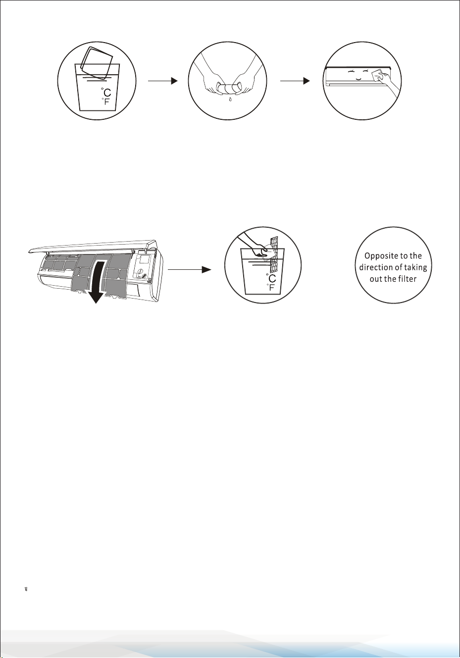
Cleaning the Filter
1. Remove the Filter: Open the unit and carefully take out the lter.
2. Clean the Filter: Wash the lter with soapy water and allow it to air dry
completely.
3. Reinstall or Replace the Filter: If the lter is damaged or worn out, replace it
with a new one.
Tip: When you notice dust accumulation on the lter, clean it promptly to ensure
clean, healthy, and ecient operation of the air conditioner.
Service and Maintenance
When the air conditioner is not in use for a long time:
1. Remove the batteries from the remote controller.
2. Disconnect the power supply to the air conditioner.
When resuming use after long-term shutdown:
1. Clean the unit and lter screen.
2. Inspect the air inlet and outlet of both the indoor and outdoor units for
obstructions.
3. Ensure the drain pipe is unobstructed.
4. Reinstall the batteries in the remote controller and verify the power is on.
<40
(104 )
<40
(104 )
www.SereneLifeHome.com
www.SereneLifeHome.com
45
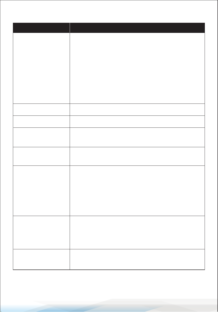
Troubleshooting
Malfunction Possible Causes
The appliance does
not operate
• Power failure or plug pulled out.
• Damaged indoor/outdoor unit fan motor.
• Faulty compressor thermomagnetic circuit breaker.
• Faulty protective device or blown fuses.
• Loose connections or unplugged power cord.
• The unit may stop operating temporarily to protect itself.
• Voltage is outside the specied operating range.
• Active TIMER-ON function.
• Damaged electronic control board.
Strange odor Dirty air lter.
Noise of running water Backow of liquid in the refrigerant circulation system.
A ne mist comes
from the air outlet
This occurs when the air in the room becomes very cold,
such as in COOLING or DEHUMIDIFYING/DRY modes.
A strange noise can
be heard
Expansion or contraction of the front panel due to
temperature variations (normal and not a fault).
Insucient airow
(hot or cold)
• Unsuitable temperature setting.
• Air conditioner intakes or outlets are blocked.
• Dirty air lter.
• Fan speed is set at minimum.
• Other sources of heat in the room.
• No refrigerant.
The appliance does
not respond to
commands
• Remote control is too far from the indoor unit.
• Batteries in the remote control need replacement.
• Obstacles are blocking the signal between the remote
control and the signal receiver in the indoor unit.
The display is o
• Active DISPLAY function.
• Power failure.
www.SereneLifeHome.com
46
Critical Warnings
Switch o the air conditioner immediately and disconnect the power supply
in any of the following situations:
• Unusual noises during operation.
• Faulty electronic control board.
• Blown fuses or damaged switches.
• Water spraying or foreign objects inside the appliance.
• Overheated cables or plugs.
• Strong or unusual odors emitted by the unit.
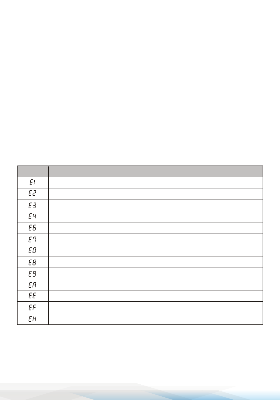
Error Codes on the Display
If an error occurs, the indoor unit display will show the following error codes:
Indoor room temperature sensor fault
Description of the trouble
Display
Outdoor pipe temperature sensor fault
Indoor pipe temperature sensor fault
Malfunction of indoor fan motor
Refrigerant system leakage or fault
Outdoor ambient temperature sensor fault
Outdoor discharge temperature sensor fault
Outdoor IPM module fault
Outdoor PCB EEPROM fault
Outdoor current detect fault
Outdoor suction temperature sensor fault
Outdoor fan motor fault
Indoor and outdoor communication fault
www.SereneLifeHome.com
47
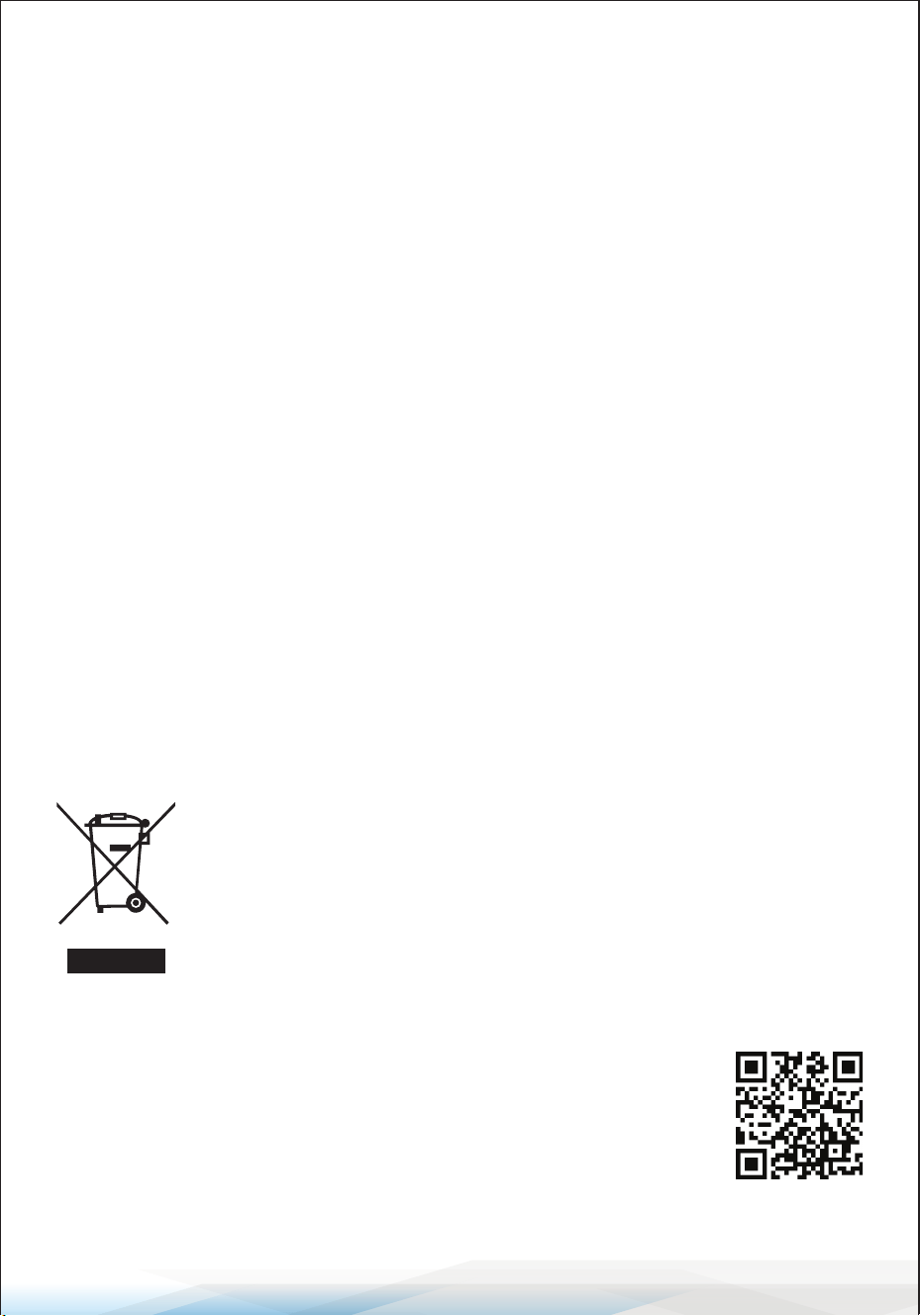
Disposal Guideline
This appliance contains refrigerant and other potentially hazardous materials.
Proper disposal is required by law to protect health and the environment.
Do Not:
• Dispose of this appliance as household or unsorted municipal waste.
• Abandon this appliance in forests, natural areas, or other non-designated places.
Proper Disposal Options:
1. Municipal Waste Collection Facility: Take the appliance to a designated
electronic waste collection site.
2. Retailer Take-Back Program: When purchasing a new appliance, your retailer
is required to accept the old appliance free of charge.
3. Manufacturer Take-Back Program: The manufacturer may provide free
collection services for old appliances.
4. Certied Scrap Metal Dealers: Sell the appliance to certied scrap metal
dealers for recycling.
Disposing of this appliance improperly endangers your health and the
environment. Hazardous substances may leak into groundwater and harm
the ecosystem. Follow these guidelines for safe and responsible disposal.
Register Product
Thank you for choosing SereneLife. By registering your product,
you ensure that you receive the full benets of our exclusive
warranty and personalized customer support.
Complete the form to access expert support and to keep your
SereneLife purchase in perfect condition.
Start Here
Serenelifehome.com/pages/register
Model Number:
SLSPLT9IN

Questions or Comments?
We are here to help!
Phone: 1.718.535.1800
Serenelifehome.com/ContactUs

