1
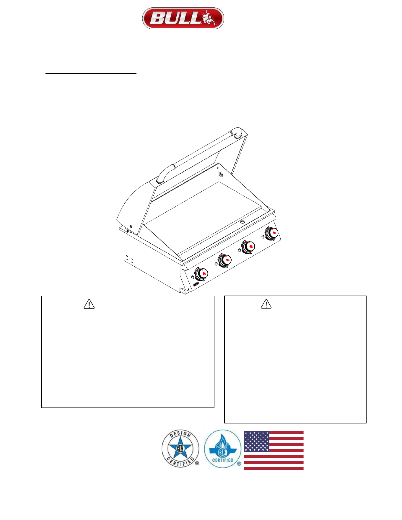
30 INCH COMMERCIAL GRIDDLE
OWNER’S MANUAL
SKU# 92008 LIQUID PROPANE (LP)
SKU# 92009 NATURAL GAS (NG)
DANGER
If you smell gas:
•
Shut off gas to the appliance.
•
Extinguish any open flame.
•
Open lid.
•
If odor continues, keep away from
the appliance and immediately call
your gas supplier or your
fire department.
WARNING
•
Do not store or use gasoline
or other flammable liquids
or vapors in the vicinity of
this or any other appliance.
•
An LP cylinder not
connected for use shall
not be stored in the
vicinity of this or any
other appliance.
USA EDITION
2
PLEASE READ THE ENTIRE OWNERS MANUAL CAREFULLY AND RETAIN FOR FUTURE
REFERENCE
We care about your safety, so please ….
• BE SURE YOUR GRIDDLE IS PROPERLY INSTALLED ASSEMBLED AND CARED FOR. FAILURE TO FOLLOW
INSTRUCTIONS IN THIS MANUAL MAY RESULT IN SERIOUS BODILY INJURY AND/OR PROPERTY DAMAGE. IF YOU HAVE
QUESTIONS CONCERNING ASSEMBLY OR OPERATION, CONSULT YOUR DEALER OR APPLIANCE SERVICE
REPRESENTATIVE FOR ASSISTANCE.
• NOTE TO ASSEMBLER, PLEASE RETURN THIS MANUAL TO CONSUMER AFTER INSTALLATION.
• NOTE TO CONSUMER, RETAIN THIS MANUAL FOR FUTURE REFERENCE.
• THIS PRODUCT IS NOT INTENDED FOR USE IN OR ON RECREATIONAL VEHICLES AND OR BOATS.
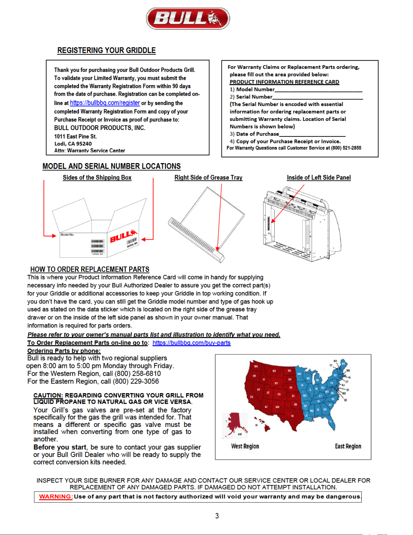
REGISTERING YOUR GRIDDLE LOCATIONS OF SERIAL NUMBER………………………………………………………………………….3
REPLACEMENT PARTS LIST AND EXPLODED ILLUSTRATION………………………………………………………………………………4
SAFETY INSTRUCTIONS………………………………………………………………………………………………………………………………5
CHECKING FOR GAS LEAKS ......................................................................................................................................................................
5
NATURAL GAS SAFETY ...................................................................................................................................................................... 6
PROPANE GAS SAFETY ..................................................................................................................................................................... 6
INSTALLATION INSTRUCTIONS
SPECIFICATIONS FOR GRIDDLE STRUCTURE ................................................................................................................................ 7
ENCLOSURE VENTILATION ............................................................................................................................................................... 7
OVERHEAD VENTILATION .................................................................................................................................................................. 8
NATURAL GAS CONNECTIONS........................................................................................................................................................... 9
PROPANE GAS CONNECTIONS ........................................................................................................................................................ 10
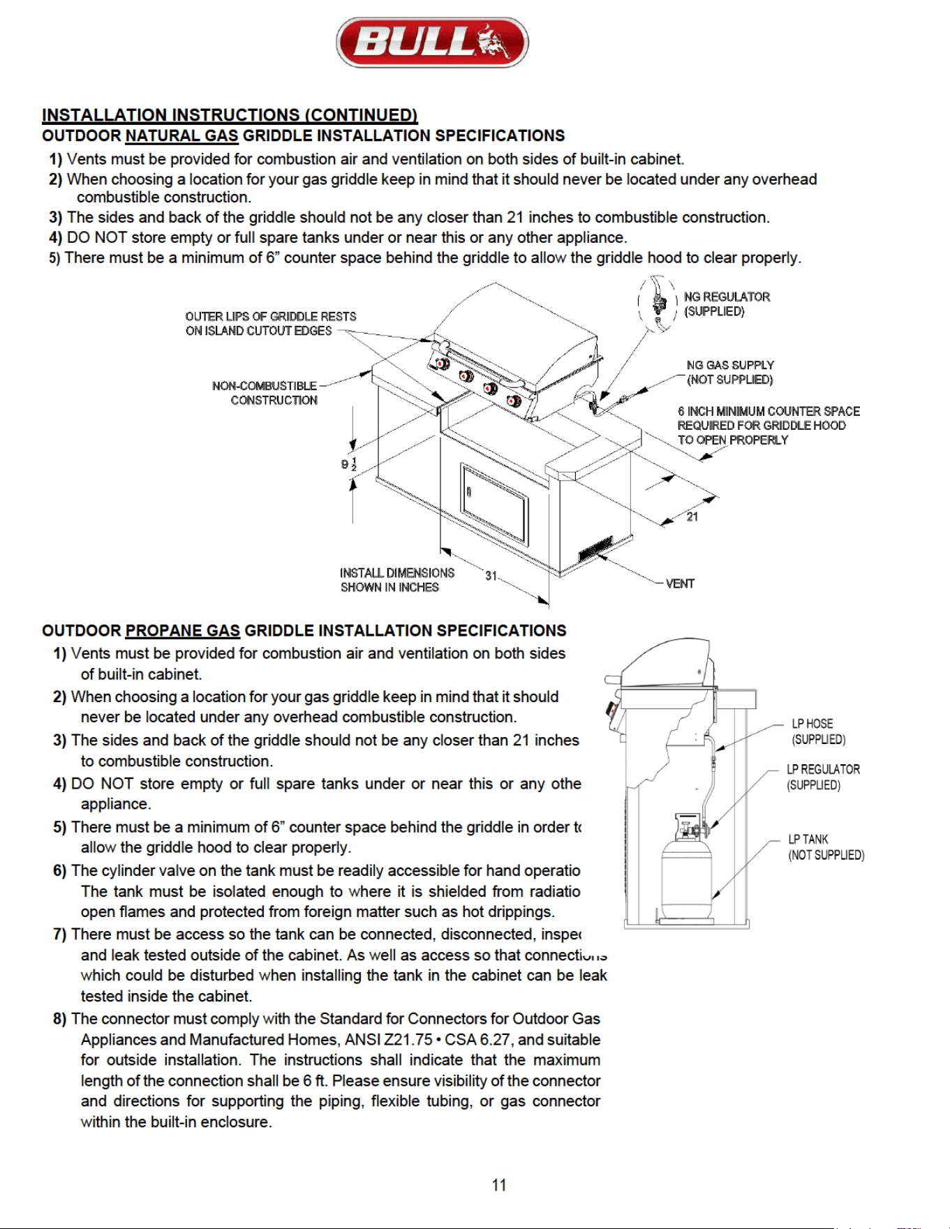
OUTDOOR PROPANE GAS GRIDDLE INSTALLATION SPECIFICATIONS ..................................................................................... 11
OUTDOOR NATURAL GAS GRIDDLE INSTALLATION SPECIFICATIONS ...................................................................................... 11
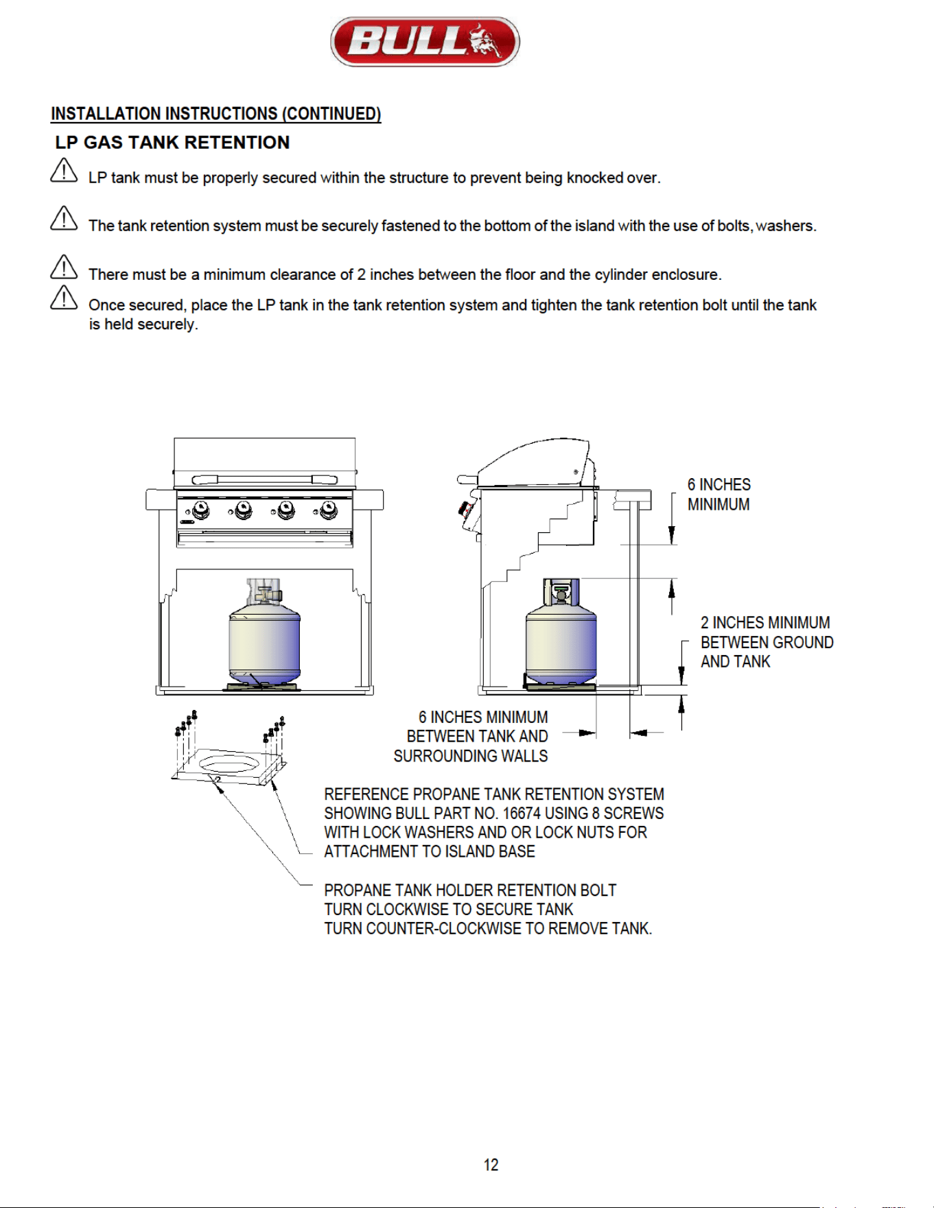
LP GAS TANK RETENTION ................................................................................................................................................................ 12
REMOVAL, INSPECTING AND CLEANING BURNERS AND GAS VALVE ORIFICES
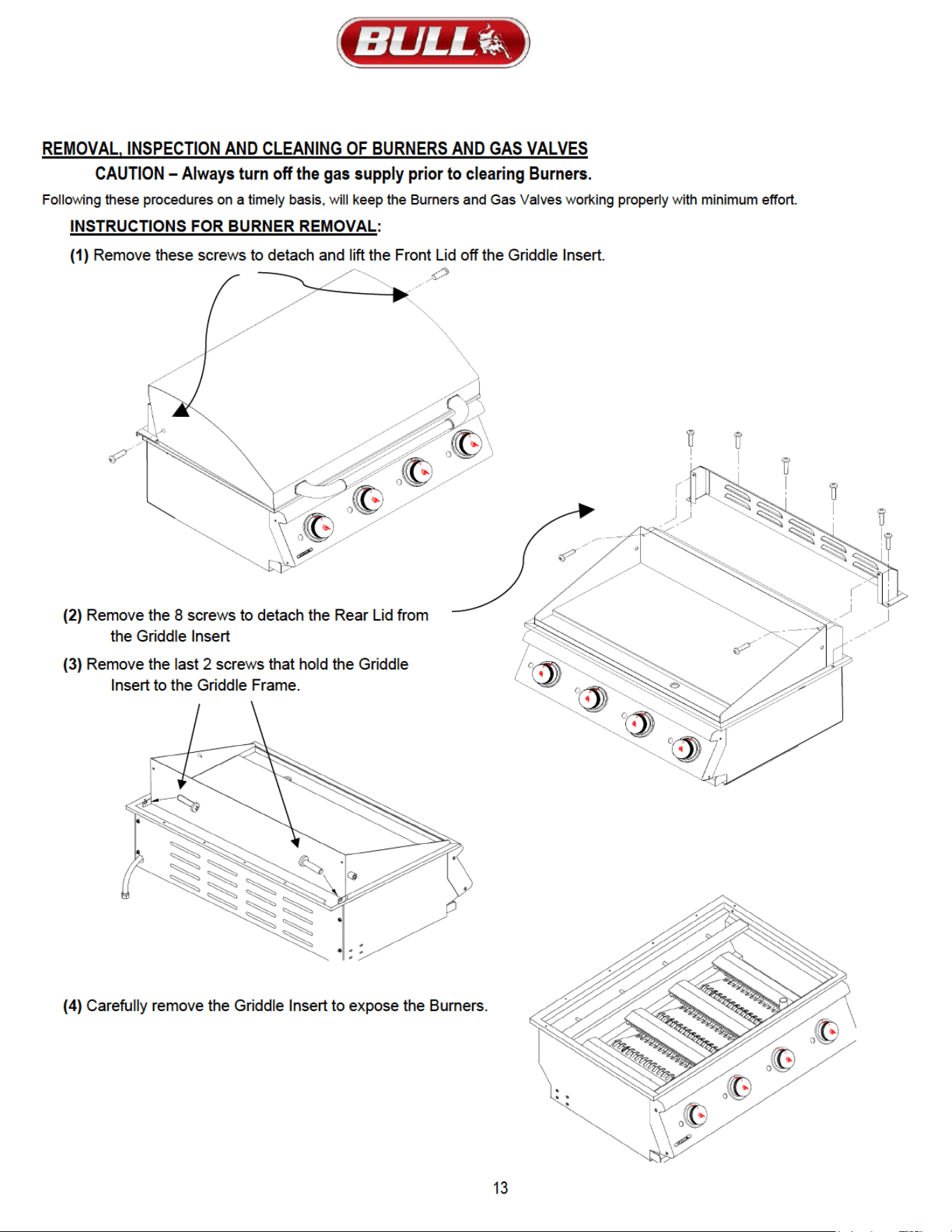
BURNER REMOVAL, INSPECTION AND CLEANING ....................................................................................................................... 13
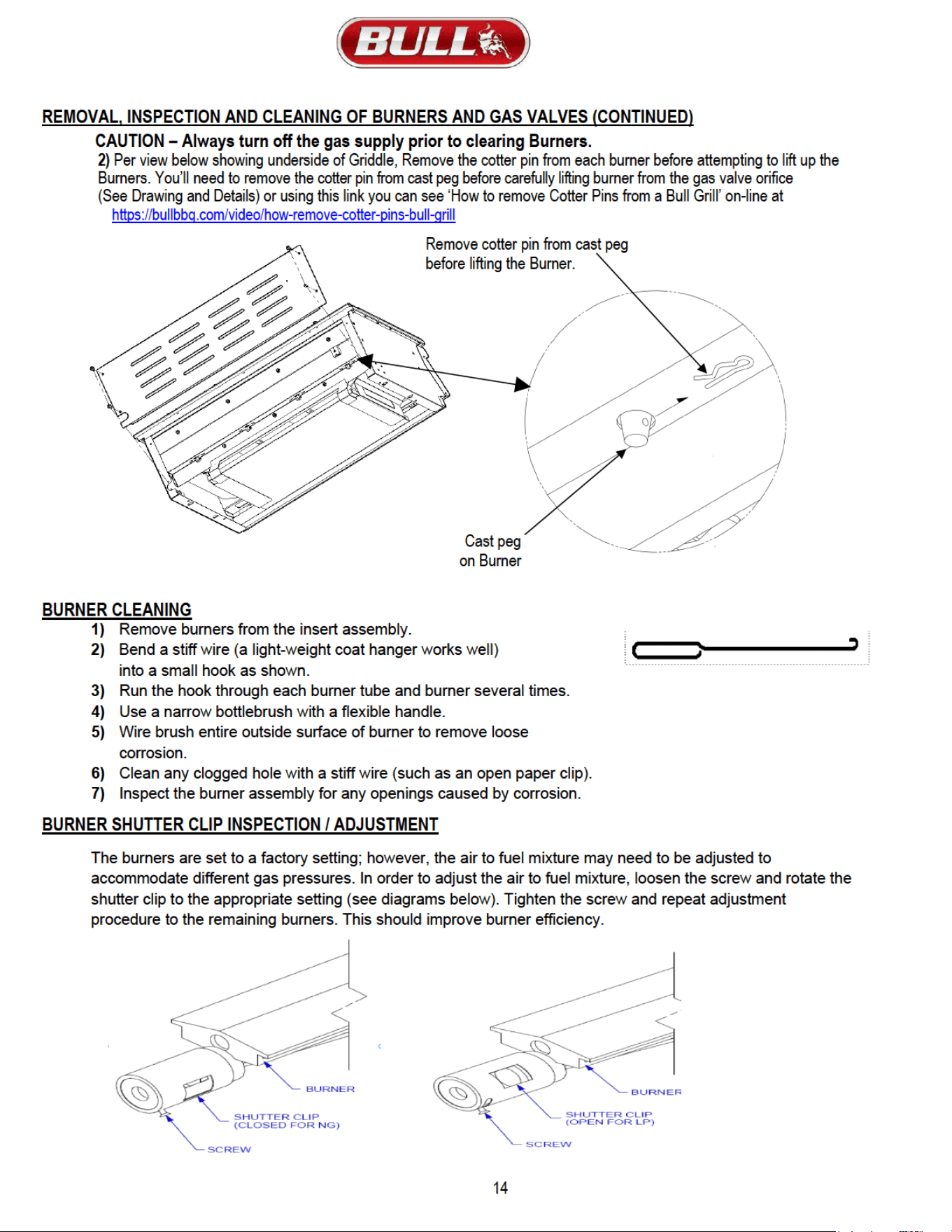
BURNER SHUTTER CLIP INSPECTION / ADJUSTMENT ................................................................................................................. 14
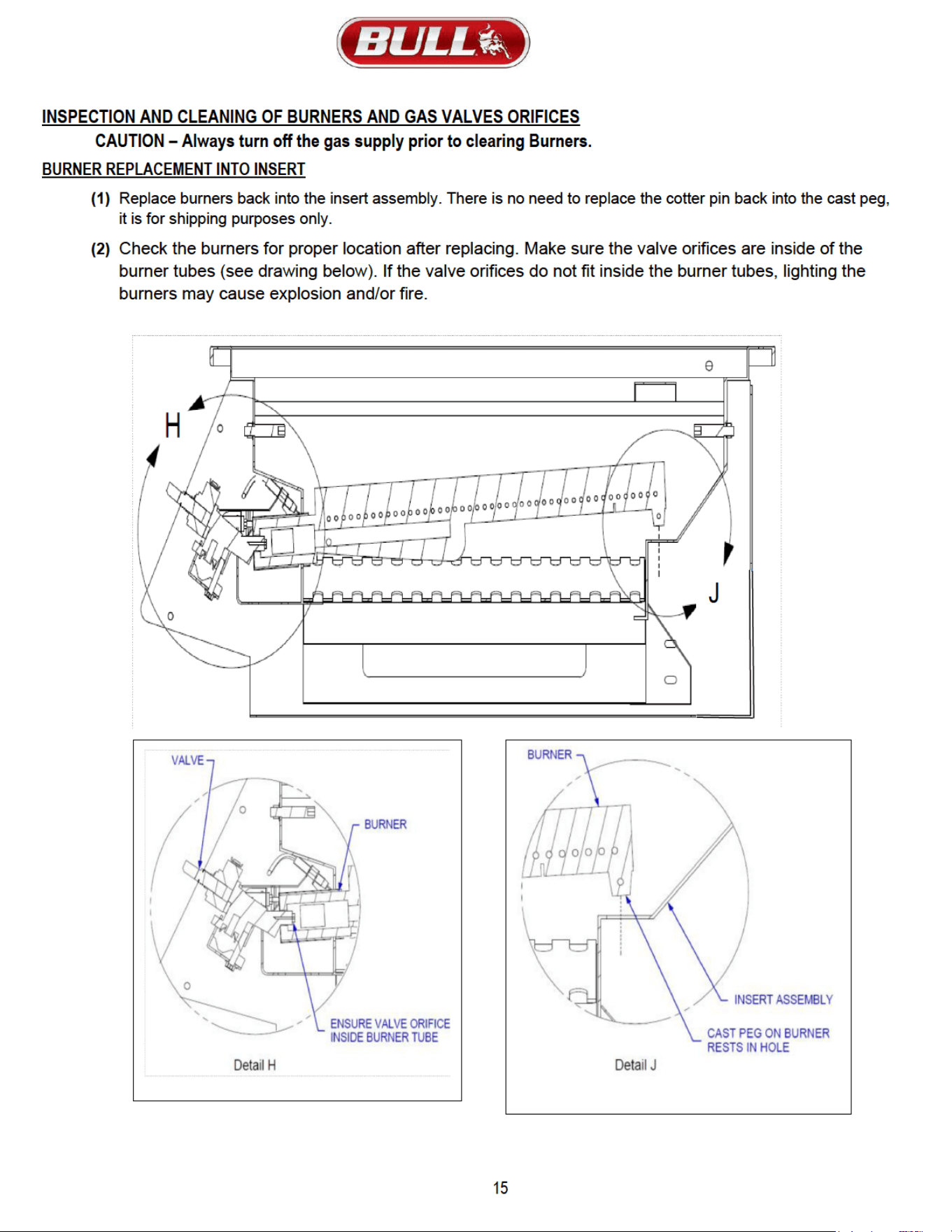
BURNER REPLACEMENT INTO INSERT ..........................................................................................................................................
15
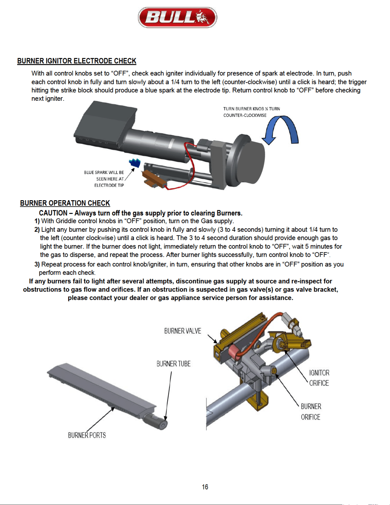
IGNITOR / ELECTRODE CHECK ........................................................................................................................................................ 16
BURNER OPERATION CHECK............................................................................................................................................................17
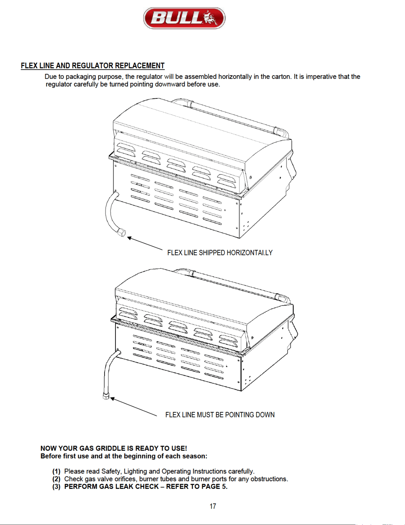
FLEX LINE AND REGULATOR PLACEMENT ..................................................................................................................................... 17
LIGHTING & OPERATING INSTRUCTIONS
LIGHTING PROCEDURES ................................................................................................................................................................... 18
OPERATING PROCEDURE ................................................................................................................................................................ 18
CLEANING & MAINTENANCE ..................................................................................................................................................................... 19
TROUBLESHOOTING
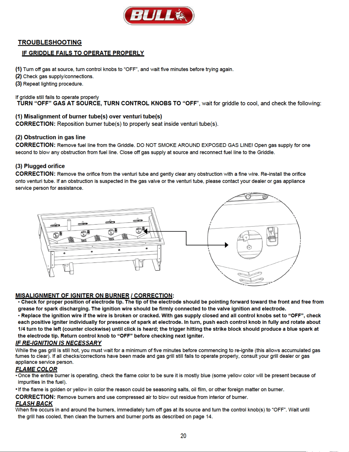
IF GRIDDLE FAILS TO OPERATE PROPERLY ................................................................................................................................... 20
YELLOW FLAME ................................................................................................................................................................................... 20
FLASH BACK ........................................................................................................................................................................................ 20
LIMITED WARRANTY ..................................................................................................................................................................................... 21-23
- READ THE FOLLOWING INSTRUCTIONS CAREFULLY AND BE SURE YOUR GRIDDLE IS PROPERLY INSTALLED, ASSEMBLED AND CARED FOR.
FAILURE TO FOLLOW THESE INSTRUCTIONS MAY RESULT IN SERIOUS BODILY INJURY AND/OR PROPERTY DAMAGE. IF YOU HAVE QUESTIONS
CONCERNING ASSEMBLY OR OPERATION, CONSULT YOUR DEALER, GAS APPLIANCE SERVICE REPRESENTATIVE OR YOUR GAS COMPANY.
-NOTE TO INSTALLER:
LEAVE THESE INSTRUCTIONS WITH THE CONSUMER AFTER INSTALLATION.
- NOTE TO THE CONSUMER:
RETAIN THESE INSTRUCTIONS FOR FUTURE REFERENCE.
- THIS OUTDOOR COOKING GAS APPLIANCE IS NOT INTENDED TO BE INSTALLED IN OR ON RECREATIONAL VEHICLES AND/OR BOATS.
FOR WARRANTY PURPOSES, PLEASE RECORD YOUR MODEL NUMBER, SERIAL NUMBER, DATE OF PURCHASE USING THE PRODUCT INFORMATION CARD
PROVIDED ON PAGE 3 AND A COPY OF YOUR RECEIPT AND OR INVOICE
v.2024.10.29
WARNING:
Fuels used in gas or oil-fired appliances and the
products of combustion of such fuels, contain chemicals known to
the State of California to cause cancer, birth defects and/or
reproductive harm. This warning is issued pursuant to California
Health & Safety Code Sec. 25249.6
.
4
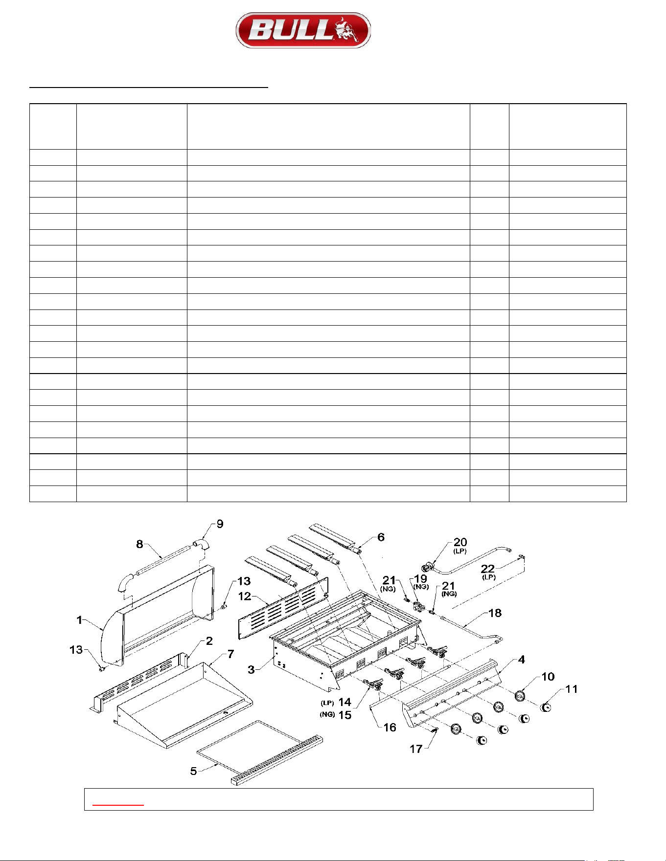
REPLACEMENT PARTS LIST & ILLUSTRATION
SKU # 92008 LP (LIQUID PROPANE) & SKU# 92009 NG (NATURAL GAS)
REF#
ON
DWG
BELOW
PART #
DESCRIPTION
QTY
WARRANTY PERIOD
(SHOWN IN YEARS)
1 92010 LID - FRONT 1 1
2 92011 LID - REAR 1 1
3 92012 INSERT ASSEMBLY 1 Lifetime
4 92013 CONTROL PANEL 1 1
5 47011 GREASE TRAY 1 1
6 44305 WELDED STAINLESS STEEL BURNER 4 5
7 92014 GRIDDLE INSERT 1 3
8 16523 LID HANDLE CENTER BAR 1 3
9 16522 LID HANDEL END CAP 2 3
10 16629 BEZEL - MAIN BURNER 4 1
11 16613 KNOB - MAIN BURNER 4 1
12 47024 BACK PANEL 1 1
13 92016 BULL GRIDDLE HOOD INSTALL PIECE 2
14 16525 (LP ONLY) GAS VALVE, MAIN BURNER (LIQUID PROPANE ONLY) 4 1
15 16524 (NG ONLY) GAS VALVE, MAIN BURNER (NATURAL GAS ONLY) 4 1
16 26103 MANIFOLD 1 3
17 16577 LOGO 1
18 47006 STAINLESS FLEX TUBE 1 1
19 16507 (NG ONLY) REGULATOR, (NATURAL GAS ONLY) 1 1
20 16589 (LP ONLY) LP HOSE & REGULATOR (LIQUID PROPANE ONLY) 1 1
21 16599 (NG ONLY) REGULATOR ADAPTER (NATURAL GAS ONLY) 2 1
22 16598 (LP ONLY) FLARE TO FLARE UNION (LIQUID PROPANE ONLY) 1 1
WARNING: Use of any part that is not factory authorized will void your warranty and may be dangerous.
5
SAFETY INSTRUCTIONS
This gas griddle must be installed in accordance with local codes or, if in an area without local codes, with the latest edition of the
National Fuel Gas Code ANSI Z223.1. In Canada, installation must conform to the standard CAN/ CGA 1-b149.1 and/or .2
(Installation Code for Gas Burning Appliances and Equipment) and any local codes.
WARNING: Fuels used in gas or oil-fired appliances and the products of combustion of such fuels, contain chemicals known to the State of
California to cause cancer, birth defects and/or reproductive harm. This warning is issued pursuant to California Health & Safety Code Sec.
25249.6.
THE LOCATION FOR YOUR GRIDDLE
DO NOT use your gas griddle in garages, porches, breezeways, sheds or other enclosed areas. Your gas griddle is to be used OUTDOORS
ONLY, with at least 21 inches clearance from the back and side of any combustible surface. The griddle should not be placed under or on top
of any surface that will burn. Do not obstruct the flow of combustion and ventilation air around the griddle housing.
PROTECT CHILDREN:
Keep children away from the griddle during use and until the griddle has cooled after you are finished. Do not allow children to
operate the griddle.
WARNING! FOR YOUR SAFETY...
1) DO NOT store or use gasoline or other flammable vapors and liquids in the vicinity of this or any other appliance.
2) DO NOT store empty or full spare gas cylinders and/or chemicals under or near this or any other appliance.
3) Keep the fuel hose away from hot surfaces. Protect the fuel hose from dripping grease. Avoid unnecessary twisting of
the hose. Visually inspect the hose prior to each use for cuts, cracks excessive wear or other damage and replace if
necessary.
4) NEVER test for gas leaks with a lighted match or open flame.
5) NEVER light griddle with lid closed or before checking to ensure burner tubes are fully seated over gas valve orifices.
6) NEVER lean over cooking surface while lighting griddle. Use barbecue tools with wood handles and good quality
insulated oven mitts when operating griddle.
DANGER! IF YOU SMELL GAS...
1) Shutoff gas to the appliance at its source.
2) Extinguish any open flame.
3) Open griddle lid to release any accumulation of fumes.
4) If gas odor persists, immediately contact your gas supplier or your fire department.
CHECKING FOR GAS LEAKS NEVER TEST FOR GAS LEAKS WHILE THE GRIDDLE IS LIT!
Prior to the first use and at the beginning of each new season (or, if using LP, whenever gas cylinder is changed), it is a must that
you check for gas leaks.
Follow these steps:
1) Make a soap solution by mixing 1 part liquid detergent and one part water.
2) Turn off heat control valves, and then turn on gas at source.
3) Apply the soap solution to all gas connections: bubbles will appear in the soap solution if connections are not properly
sealed Tighten or repair as necessary.
4) If you have a gas leak that you cannot repair, turn off the gas at the source, disconnect fuel line from the double side burner
and immediately call your dealer and gas supplier for professional assistance.
WHEN THE OUTDOOR COOKING GAS APPLIANCE IS NOT IN USE
WARNING: When the outdoor cooking gas appliance is not in use, the gas must be turned off at the supply cylinder. Storage of an outdoor
cooking gas appliance indoors is permissible only if the cylinder is disconnected and removed from the outdoor cooking gas appliance.
Cylinder must be stored outdoors, out of reach of children and must not be stored in a building, garage, or any other enclosed area.
Place dust cap on cylinder valve outlet whenever the cylinder is not in use. Only install the type of dust cap on the cylinder valve outlet that
is provided with the cylinder valve. Other types of caps or plugs may result in leakage of propane.
1) Do not store a spare LP gas cylinder under or near this appliance.
2) Never fill the cylinder beyond 80 percent full.
3) If the information in 1) and Clause 2) is not followed exactly, a fire causing death or serious injury may occur.
READ CAREFULLY BEFORE ASSEMBLY AND OPERATION OF YOUR GRIDDLE
6
SAFETY INSTRUCTIONS (CONTINUED)
NATURAL GAS SAFETY:
1) Your Natural Gas griddle is designed to operate on natural gas ONLY, at a pressure of 4” water column (W.C.)
regulated at the natural gas regulator attached at the back of the griddle. Check with your gas utility for local gas
pressure and with your local municipality for building code requirements.
2) Check with your gas utility or with local building codes for instructions to install gas supply line or call a licensed and
knowledgeable installer.
3) It is recommended that an “ON-OFF” shutoff valve be installed at the gas supply source:
4) Outdoors after gas line piping exits outside wall or before gas line piping enters ground.
5) Indoors in the branch fuel line in an accessible location near the supply line.
6) Do not use Teflon ® tape or pipe sealant on any flare ends because you will not obtain a leak-free seal.
7) Pipe sealing compound or pipe thread tape of the type resistant to the action of natural gas must be used on all
male pipe thread. Apply compound or tape to at least the first three threads when making the connection.
8) The outdoor cooking gas appliance and its individual shut-off valve must be disconnected from the gas supply
piping system during any pressure testing of that system at test pressures in excess of 0.5 psi (3.5 kPa)
9) The outdoor cooking gas appliance must be isolated from the gas supply piping system by closing its individual
manual shut-off valve during any pressure testing of the gas supply piping system at test pressures equal to or
less than 0.5 psi (3.5 kPa)
10) Turn off your gas griddle when the gas supply is being tested at low pressures. This appliance must be isolated
from the gas supply piping system by closing its individual valve.
WARNING:
Gas valves are preset at the factory to operate on LP or natural gas. If you wish to convert to a different gas type, be
sure to contact your griddle dealer, licensed plumber or authorized service center for further details. Conversion kits
are not sold to the general public and require a professional to perform service. Failure to properly convert a unit can
cause serious injury to yourself and/or others, irreparable damage to your griddle and void of warranty.
PROPANE GAS SAFETY:
1) Your Propane gas griddle is designed to operate on propane gas ONLY, at a pressure regulated at 11” water column
(W.C.) when equipped with the correct propane orifices on the valves and a propane regulator on the supply line
regulated at the residential meter.
2) Your propane gas griddle is designed to be used with a standard 20 lb. gas cylinder with size of 18.1 / 46cm (Height) /
* 12.5 in /32cm (Width). In the United States, the gas cylinder must be constructed and marked in accordance with
specifications of the US Department of Transportation for Propane Gas Cylinders.
• Always keep cylinder securely fastened in an upright position.
• Never connect an unregulated propane gas cylinder to the griddle. Do not subject propane cylinders to
excessive heat.
CAUTION:
Never store a propane gas cylinder inside a building or in the vicinity of any gas-burning appliance.
WARNING
• Do not store a spare or disconnected liquid propane cylinder under or near this appliance.
• A dented or rusty liquid propane cylinder may be hazardous and should be check by your liquid propane provider.
• Do not use a liquid propane cylinder with a damaged valve.
BEWARE OF SPIDERS
CAUTION: BURNERS MUST BE INSPECTED AND CLEANED BEFORE FIRST USE.
Spiders and small insects occasionally spin webs or make nests in the burners during warehousing, transit and/or
after long periods of non- use. These webs can lead to a gas flow obstruction, which could result in a fire in and
around the burner tubes. This type of fire is known as “FLASH-BACK” and can cause serious damage to your
griddle and create an unsafe operating condition for the user. Although an obstructed burner tube is not the only
cause of “FLASH BACK” it is the most common cause, and frequent inspection and cleaning of the burners is
necessary.
7
INSTALLATION INSTRUCTIONS
Your built-in gas griddle comes to you fully assembled. We strongly recommend professional installation and hookup of the gas griddle.
These instructions will provide you with the measurements necessary for you or your builder to construct a masonry structure to house
your outdoor gas griddle.
NOTE TO INSTALLER: Leave these instructions with the consumer for future reference. The griddle must be installed in accordance
with all local building codes.
NOTE: Please remove the cotter pins from the burners before installing unit into an island. See page 12 for cotter pin removal.
SPECIFICATIONS FOR BARBECUE STRUCTURE:
1) Your choice of masonry can be used for cabinet construction for the built-in gas griddle; however, it must be non-combustible
material.
2) Keep in mind when choosing a location for your griddle that it should NOT be located under any overhead combustible construction.
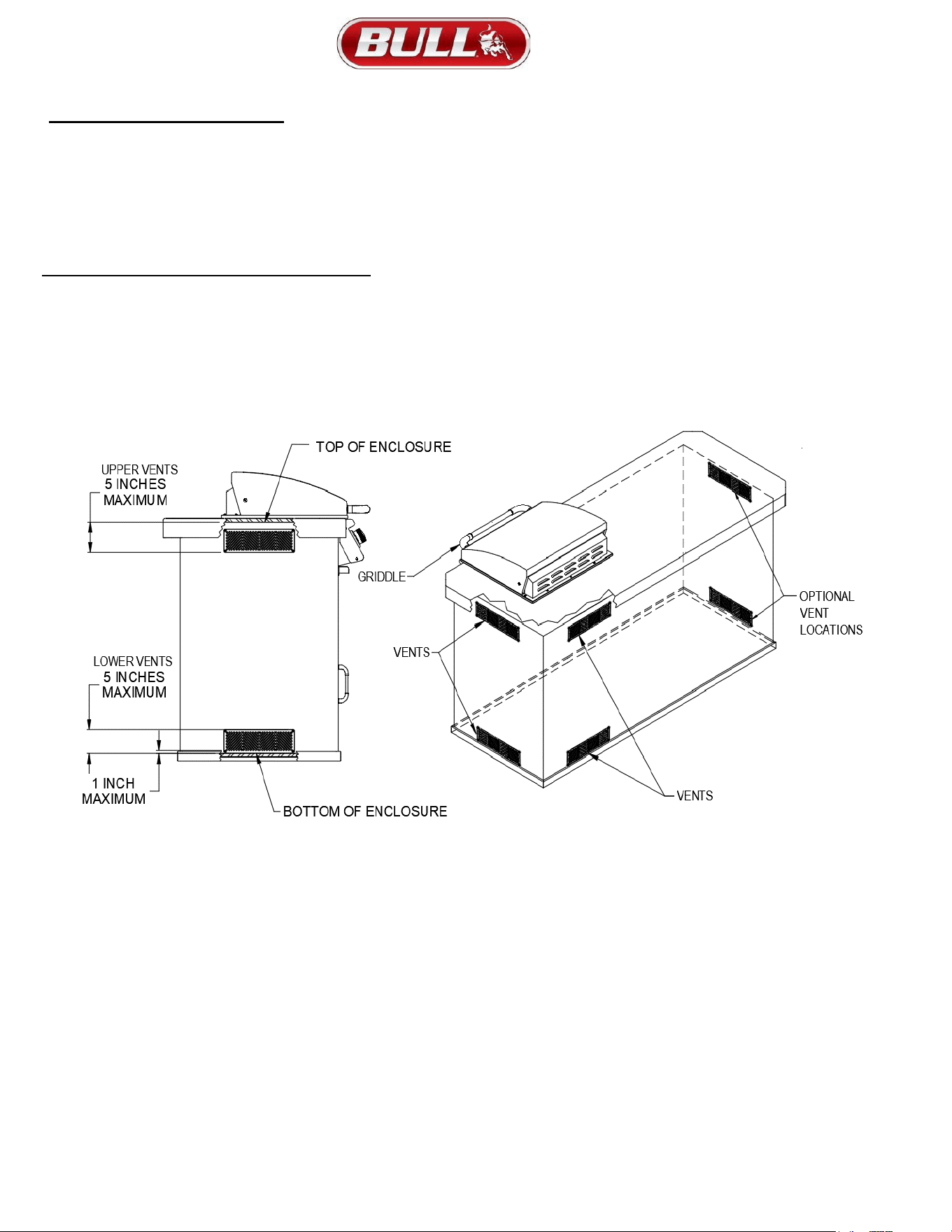
3) Upper and lower-level vents must be provided for combustion air on both sides of built-in cabinet.
4) Vents on griddle insert must remain unobstructed to allow for combustion air and ventilation.
5) Upper vents must be located within 5 inches from the top of the island enclosure to the bottom of the vent.
6) Lower vents must be located within 1 inch from the bottom of the island enclosure to the bottom of the first vent openings
and no more than 5 inches from the bottom of the island enclosure to the top of the vent.
7) If not using Bull vents, the vents you use must meet ANSI Standard codes.
8) The upper vents must have openings that have a total free area of not less than 1 sq in per lb of stored fuel capacity per
vent and the lower vents must have openings that have a total free area of not less than 1/2 sq in per lb of stored fuel
capacity per vent.
9) Both upper and lower vent openings must have minimum dimensions to permit the entrance of a 1/8 in diameter rod.
10) The griddle requires a wall opening of the following dimensions: See PAGE 10 for different models.
11) Place gas griddle assembly into wall opening as shown in illustration on pages 10. Griddle rests on side and back edges
of the griddle insert.
12) For propane gas LP TANK STORAGE AREA MUST BE ISOLATED FROM GRIDDLE AND VENTED.
13) Do not use any combustible materials for this construction. Minimum horizontal clearance to adjacent combustible
surface from side and back of the griddle must be 21 inches. A 6-inch clearance is required behind griddle to allow front
portion of hood to open and for ventilation purposes.
8
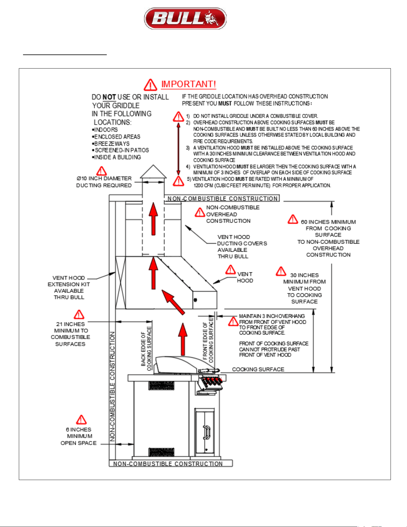
OVERHEAD VENTILATION
9
INSTALLATION INSTRUCTIONS (CONTINUED
)
CONNECTING TO GAS SOURCE
Refer to the following instructions and illustrations for typical gas supply connections. We strongly suggest professional
installation and hook-up of the gas griddle.
IMPORTANT: Before connecting griddle to gas source, make sure griddle control knobs are in “OFF” position.
Be sure to follow instructions for connecting an appliance to a fixed fuel piping system specifying the use of a rigid pipe,
semi-rigid tubing, and/or a connector that complies with the Standard for Connectors for Outdoor Gas Appliances and
Manufactured Homes, ANSI Z21.75 * CSA 6.27.
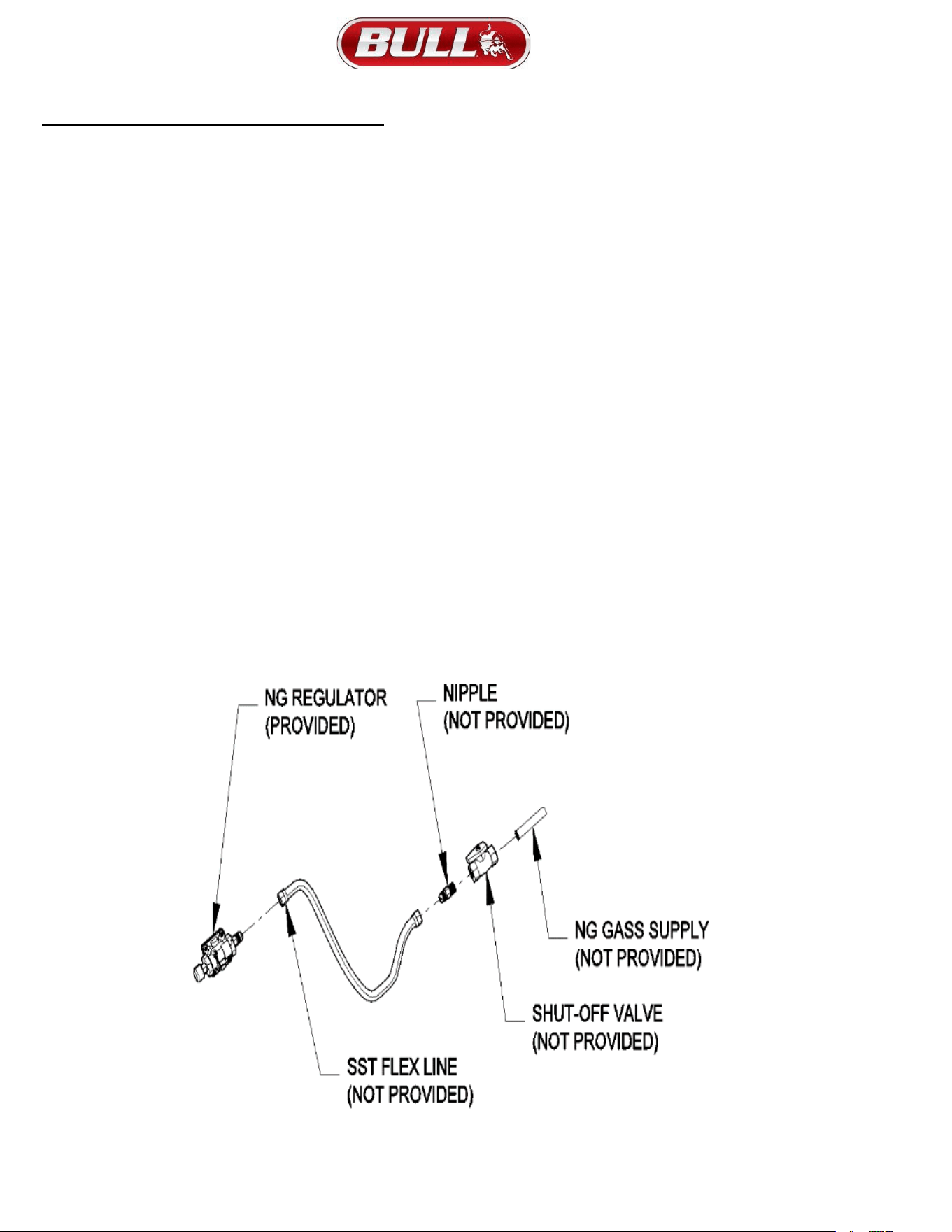
NATURAL GAS CONNECTIONS
IMPORTANT: Bull Outdoor Products does not recommend the use of any quick
connect fittings or lines to the unit. Use of
these types of fittings or lines could cause low gas flow and greatly reduce the performance of the unit.
1) Do not use Teflon ® tape or pipe sealant on any flare ends because you will not obtain a leak-free seal.
2) Remove plastic cap from regulator installed on grill.
3) Attach stainless steel flex line 3/8” flare-female end to the regulator.
4) Attach the other end of flex line to shut-off valve through a nipple.
5) Attach a shut-off valve to gas supply pipe.
TO PERFORM GAS LEAK CHECK – REFER TO PAGE 5
10
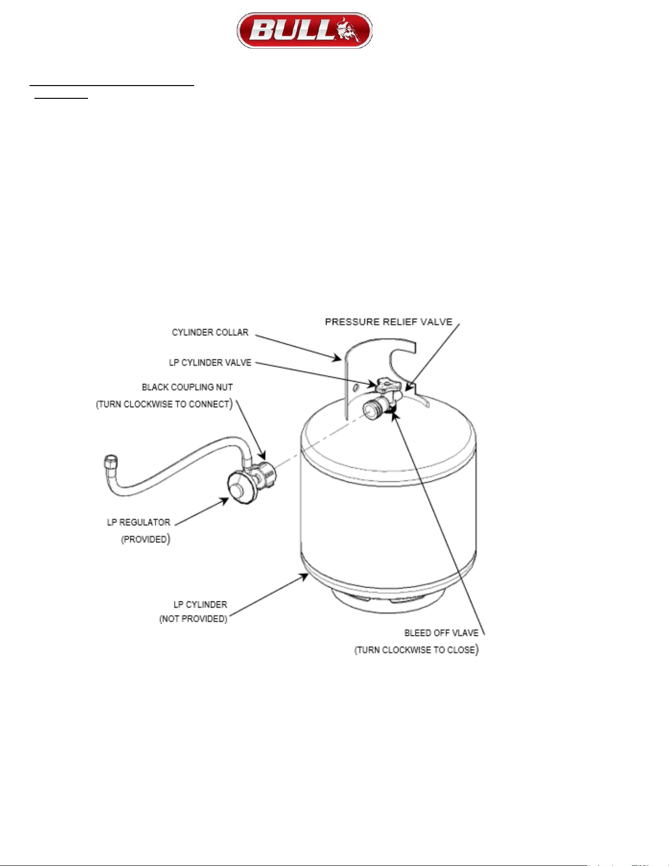
PROPANE GAS CONNECTIONS
CAUTION: Changing the gas tanks must be done away from any source of ignition.
LP Gas Tank must be marked in accordance with the Specifications for LP Gas Cylinders, Spheres and Tubes for
Transportation of Dangerous Goods and Commission LP Gas Tank connection device is compatible with outdoor cooking
appliances.
1) LP Gas Tank has appropriate vapor withdrawal.
2) LP Gas Tank must include a collar to protect the cylinder valve.
3) LP Gas Tank uses a type 1 tank valve that is firmly
secured in an upright position.
4) LP Gas pressure regulator and hose assembly supplied with this unit must be used without alteration and must be less
than 59 inches in length.
5) If the hose assembly needs to be replaced, use only the type 1 specified in the parts list supplied with this unit. The
replacement hose assembly shall be that specified by the manufacturer.
6) To connect, turn the black coupling nut of the hose and regulator assembly in a clockwise direction (see illustration below)
until it is completely threaded onto the cylinder valve before turning gas supply on. To remove turn the black coupling nut
of the hose and regulator assembly in a counter-clockwise direction.
7) LP Gas Tank must have a listed overfilling prevention device.
When installing a LP gas supply, the following criteria must be met:
1) LP cylinder must be marked in accordance with the Specifications for LP gas Cylinders,
Spheres and Tubes for Transportation of Dangerous Goods and Commission, CAN/CSAB339, as applicable.
2) Must have a listed overfilling prevention device.
3) A cylinder connection device compatible with the connection for outdoor cooking appliances.
4) The cylinder must be equipped with an arrangement for vapor withdrawal.
5) The cylinder must include a collar to protect the cylinder valve.
18
BURNER LIGHTING PROCEDURE
(1) Become familiar with the safety guidelines at the front of the manual.
NEVER SMOKE WHILE LIGHTING GRIDDLE OR CHECKING GAS SUPPLY CONNECTIONS!
(2)
If your griddle fuel source is a LP gas cylinder, check to see that cylinder is filled.
(3) Check that the end of each burner tube is properly located over each valve orifice.
(4) Make sure all gas connections are securely tightened.
TEST FOR LEAKS WITH A SOAP SOLUTION, NEVER WITH A FLAME.
(Gas Leak Check instructions are on page 5).
(5) Always open lid before lighting.
(6) Set ALL griddle control knobs to “OFF” and open gas supply, LP cylinder or Natural Gas Valve.
(7) Ignite only the burners you intend to use, using the same method for each: Push in control knob completely and rotate slowly (3 to 4
seconds) about 1/4 turn to the left (counter clockwise) until a click is heard. The 3 to 4 second duration should provide enough gas to
light the burner. If the burner does not light, immediately return the control knob to ‘OFF’, wait 5 minutes for the gas to disperse, and
repeat the process. After burner ignites, repeat procedure with any other burner needed.
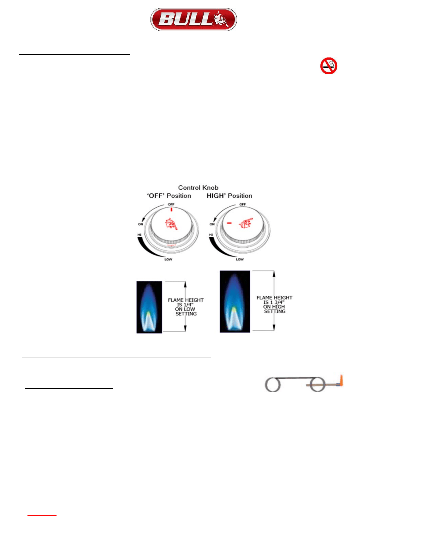
(8) Adjust control knob(s) to desired cooking temperature.
INSTRUCTIONS FOR MANUALLY LIGHTING YOUR GRILL
1) Before attempting to manually light grill you should wait 5 minutes after last attempt with grill ignitor to allow any accumulated gas to
dissipate.
2) Clip a paper match to lighting rod (match holder) provided with your grill as shown
OPERATING PROCEDURE
(1) WARNING! GRIDDLE HOOD NEEDS TO STAY OPEN WHILE IN USE
(2) Burn-off: Before cooking on your gas griddle for the first time, burn the griddle to get rid it of any odors or foreign matter by
igniting the burners, closing the lid, and operating at “HIGH” setting for about five minutes. You may then either set the controls to
“OFF” or cook on your griddle immediately by turning the control knobs to a lower setting.
(3) CAUTION: DO NOT LEAVE GRIDDLE UNATTENDED WHILE IN USE.
(4) Preheating: It is necessary to preheat the griddle for a short time before cooking certain foods, depending on the type of food and the
cooking temperature. Food that requires a high cooking temperature needs to preheat for five minutes; food that requires a lower
cooking temperature needs only a period of two to three minutes. There is no need to preheat for foods that require slow cooking.
(5) CAUTION: If burners go out during operation, close gas supply at source, and turn all gas valves off. Open lid and wait five
minutes before attempting to re-light (this allows accumulated gas fumes to clear).
(6) CAUTION: Should a grease fire occur, close gas supply at source, turn off all burners and leave lid closed until fire is out. Do not
use water or any liquid to extinguish a grease fire.
(7) CAUTION: Do not attempt to disconnect any gas fitting while your griddle is in operation or while gas feed is on.
WARNING: ANY MODIFICATION OF THE APPLIANCE MAY BE DANGEROUS TO YOU OR OTHERS AND MAY VOID PRODUCT WARRANTY
19
CLEANING AND MAINTENANCE
(1) Keeping outdoor cooking gas appliance area clear and free from combustible materials, gasoline and other flammable
vapors and liquids.
(2) Not obstructing the flow of combustion and ventilation air.
(3) Keeping the ventilation opening(s) of the cylinder enclosure free and clear from debris.
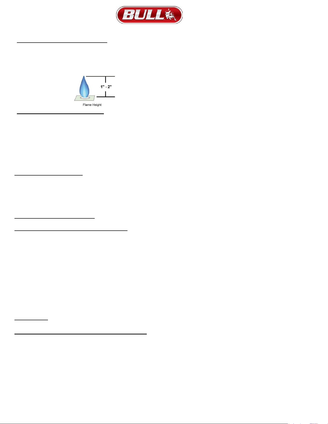
(4) Visually checking burner flames including pilot burner flame if provided, with pictorial representations.
CLEANING THE GRIDDLE INSERT
If grease is allowed to accumulate on the griddle surface, it will carbonize and become difficult to remove. In
order to avoid this, regular maintenance and cleaning is required.
(1) To clean griddle surface, follow these steps:
(2) Remove excess oil, grease and food with a thin scraper.
(3) Use a damp, non-abrasive cloth with a non-chlorinated cleaner.
(4) Wipe surface with the clean damp cloth.
DO NOT use steel wool, abrasives or griddle stones on the griddle surface.
DO NOT use any type of grill cleaner on the griddle surface.
DO NOT hit the griddle surface with any sharp object or utensil.
CLEANING THE BURNERS
(1) Remove burners from griddle by carefully lifting each burner up and away from gas valve orifice.
(2) Wire brush entire outer surface of burner to remove residue and dirt. Clean any clogged ports with a stiff wire
such as an open paper clip.
(3) Inspect the burner for damage (cracks or holes) and if such damage is found, order and install a new burner.
(4) After installation, be sure to check that gas valve orifices are correctly placed inside ends of burner tubes. Also
check position of spark electrode.
CLEANING THE GREASE TRAY
The grease tray should be emptied and wiped down periodically and washed in a mild detergent and warm water solution.
ANNUAL CLEANING OF GRIDDLE HOUSING
Cleaning the griddle after every cookout will keep it ready for instant use. However, periodically the griddle should be
given an entire thorough cleaning to ensure optimal performance.
(1) Shut off gas supply at source and disconnect fuel line from gas valve manifold. Protect fuel line fitting.
(2) Remove and clean (as explained above) the griddle inserts, burners and grease tray.
(3) Cover the gas valve orifices with a piece of aluminum foil.
(4) Brush the inside and bottom of the insert assembly with a stiff wire brush and wash down with a mild soap and
warm water solution. Rinse thoroughly and let dry.
(5) Remove aluminum foil from orifices and check orifices for obstruction.
(6) Check electrode as instructed on page 16.
(7) Replace grease tray, burners and griddle insert.
(8) Reconnect to gas source and observe burner flame for correct operation.
IMPORTANT: You should NOT line the bottom of the griddle housing with aluminum foil, sand or any other grease
absorbent substance. Grease will not be able to drip down into the grease tray and a grease fire could occur.
STAINLESS STEEL CLEANING AND MAINTENANCE
Stainless steel is a corrosion resistant chromium/nickel alloy steel that is both durable as well as strong with an
outstanding luster. The goal of your cleaning and maintenance routine should be to keep the stainless steel’s
protective chromium oxide layer intact. This is what prevents corrosion. Contrary to popular belief, stainless steel is
NOT rustproof, especially in the environment of a swimming pool. Chlorine, bromine, some fertilizers and other
elements are extremely caustic chemicals for stainless steel. These chemicals combined with heat and humidity
greatly increase the corrosiveness of these chemicals. Regular cleaning is the best way to prevent corrosion and
add years of enjoyment to your Bull stainless steel products.

21
Warranty Policy
LIMITED WARRANTY ON BULL OUTDOOR PRODUCTS, INC., PRODUCTS
THIS LIMITED WARRANTY GIVES YOU SPECIFIC LEGAL RIGHTS. YOU MAY ALSO HAVE OTHER RIGHTS, WHICH
VARY FROM STATE TO STATE.
THIS LIMITED WARRANTY CAN ALSO BE FOUND ON OUR WEBSITE AT:
https://www.bullbbq.com/support-warranty (United States Customers)
https://www.bullbbq.eu/customer-care/#warranty-registration-form (International Customers)
AND IN THE OWNER’S/INSTALLATION MANUALS THAT WE PROVIDE WITH OUR PRODUCT
THIS LIMITED WARRANTY IS SUBJECT TO THE EXCLUSIONS, CONDITIONS AND LIMITATIONS SET FORTH
BELOW.
ANY IMPLIED WARRANTIES IMPOSED BY LAW, INCLUDING WITHOUT LIMITATION TO THE IMPLIED
WARRANTIES OF MERCHANTABILITY AND FITNESS FOR A PARTICULAR PURPOSE, ARE LIMITED IN
DURATION TO THE DURATION OF THIS EXPRESSED LIMITED WARRANTY. SOME STATES DO NOT ALLOW
LIMITATIONS ON HOW LONG AN IMPLIED WARRANTY LASTS, SO THE ABOVE LIMITATION MAY NOT APPLY
TO YOU.
WHO MAY USE THIS WARRANTY?
BULL OUTDOOR PRODUCTS, INC. located at address 1101 East Pine St. Lodi, CA. 95240
(“we”) extend this limited warranty only to the consumer who originally purchased the product (“you”) at the original
site of delivery or installation. It does not extend to any subsequent owner or other transferee of the product. It does
not extend to any rental, commercial, or non- residential application. Examples of excluded applications include, but
are not limited to day care centers, schools, bed and breakfast centers, churches, private clubs, fire stations, club
houses, Common areas in multi-family dwellings, restaurants, hotels, nursing homes, food service locations, and
institutional food service locations.
WHAT DOES THIS WARRANTY COVER?
This limited warranty covers defects in materials and workmanship of the product and product components
identified below for the Warranty Periods defined below.
WHAT IS THE PERIOD OF COVERAGE?
This limited warranty starts on the date of your purchase and lasts for the time periods specified on the next page.
The Warranty Period is not extended if we replace the product. We may change the availability of this warranty at our
discretion, but any changes will not be retroactive.

22
Warranty Policy (Continued)
Grilling/Pizza Accessories and Grill Covers DO NOT include a warranty period
Grill Warranty Periods
The following parts are covered for 1 year on all our current gas grill models:
• The lid, control panel, grease tray, bezels, knobs, temperature gauge, valves, regulator, flex tubes, rotisserie
burner, transformer, and all components of the lighting system.
The following parts are covered for 3 years on all our current gas grill models:
• The manifold, handle end caps, flame tamers, heat shields, and warming rack.
The following parts are covered for the Lifetime on all our current gas grill models:
• Insert assembly and the grates.
The warranty period for the grill burners varies by type:
• Cast stainless steel burners - Lifetime
• Welded stainless steel burners – 5 years
• Porcelain coated burners – 3 years
The warranty period for the charcoal grill is 1 year on all parts, except for the insert assembly, which is covered for 5
years.
Component Warranty Periods
All the parts for our components /grill carts/refrigerators/kegerators/drawers/doors/refrigerator frames/grill
jackets/finishing frames/ice chest/sinks/bar center are covered for 1 year with these exceptions:
• Power Burner
o The insert/grates are lifetime covered parts.
o The manifold/burner are covered for 3 years.
• Searing Station/Slide in Double Sideburner
o The grates are covered for lifetime,
o The insert for 5 years, and
o The manifold for 3 years.
• Single Sideburner
o The grates are covered for 5 years and
o The burner for 3 years.
• Sidekick
o The burner is covered for 3 years.
Pizza Ovens/Islands/Fire Features Warranty Periods
• All of the parts and construction materials are covered for 1 year.