
Technical Support and E-Warranty Certificate www. vevor. com/support
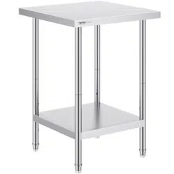
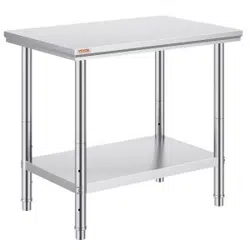
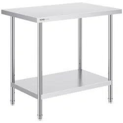
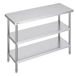
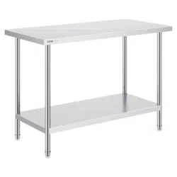
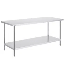
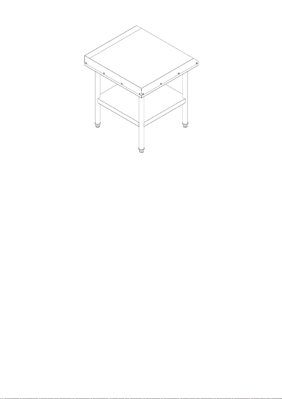
WORKBENCH
USER MANUAL
We continue to be committed to provide you tools with competitive price.
"Save Half", "Half Price" or any other similar expressions used by us only represents an
estimate of savings you might benefit from buying certain tools with us compared to the
major top brands and does not necessarily mean to cover all categories of tools offered by
us. You are kindly reminded to verify carefully when you are placing an order with us if you
are actually saving half in comparison with the top major brands.

- 1 -
Note:This user manual is
applicable
to the cotton candy machines.
Please read it carefully before use.
Have product questions? Need technical support? Please feel free to
contact us:
Technical Support and E-Warranty Certificate
www. vevor. com/support
NEED HELP? CONTACT US!
This is the original instruction, please read all manual instructions
carefully before operating. VEVOR reserves a clear interpretation of our
user manual. The appearance of the product shall be subject to the
product you received. Please forgive us that we won't inform you again if
there are any technology or software updates on our product.
HET-24*18 HET-24*30 HET-24*36
HET-24*48 HET-24*60 HET-24*72
HET-30*48 HET-30*60 HET-30*72
HET-24*30-L HET-24*36-L HET-24*48-L
HET-24*60-L HET-24*72-L
HET-24*24-3L
HETG-24*12 HETG-24*18 HETG-24*24
HETG-24*30 HETG-24*48 HETG-30*12
HETG-30*36 HETG-30*48 HETG-30*60
HETG-24*15-L HETG-24*24-L HETG-24*30-L
HETG-24*36-L HETG-24*48-L HETG-24*60-L
WORKBENCH

- 2 -
SAFETY INSTRUCTIONS
WARNING:
Read this material before using this product. Failure to do so can result
in serious injury.
Assembly precautions
1. Assemble only according to these instructions. Improper assembly can
create hazards.
2. Keep the assembly area clean and well-lit.
3. Keep bystanders out of the area during assembly.
4. Do not assemble when tired or when under the influence of alcohol, drugs
or medication.
5. The product capabilities apply to properly and completely assembled
products only.
6. For additional information regarding the parts listed in the following pages,
please refer to the Assembly Diagram of this manual. Unwrap and separate
all parts in a clean work area.
Use precautions
1. Use with products heavier than the rated weights indicated may result in
instability causing possible injury.
2. Mounts must be attached as specified in assembly instructions. Improper
installation may result in damage or serious personal injury.
3. Make sure that the supporting surface will safely support the combined
weight of the equipment and all attached hardware and components.
4. Use the mounting screws provided and DO NOT OVER TIGHTEN
mounting screws.
5. This product contains small items that could be a choking hazard if
swallowed. Keep these items away from children.
6. This product is intended for indoor use only. Using this product outdoors
could lead to product failure and personal injury.
SAVE THESE INSTRICTIONS

- 3 -
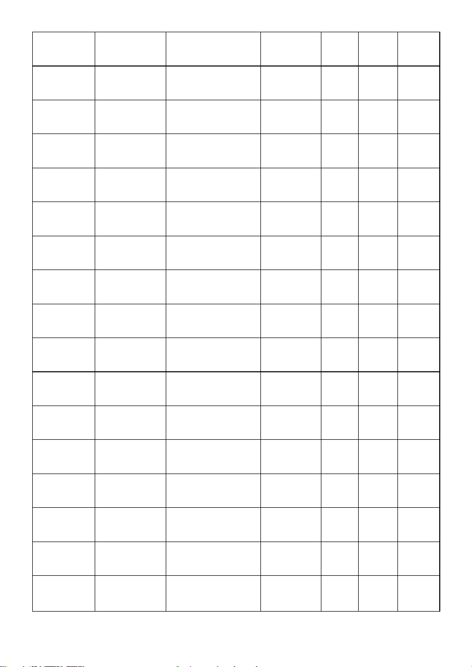
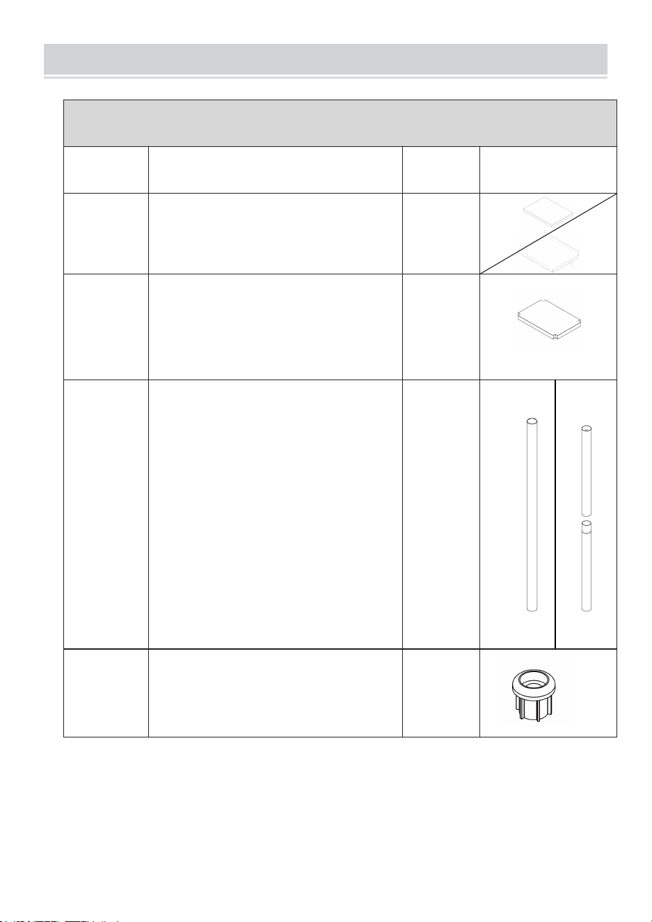
PRODUCT PARAMETERS
Item No.
Maximum
load-bearing
(Top
board/Clap
board)
Product Size
(mm)
Table
legs
( whole /
separated)
Back
boar
d
Supp
ort
feet
Wheel
HET-24*18
370/270lbs
610*457*864
separated
×
√
×
HET-24*30
400/300lbs
610*762*864
separated
×
√
×
HET-24*36
430/320lbs
610*914*864
whole
×
√
×
HET-24*48
460/340lbs
610*1219*864
whole
×
√
×
HET-24*60
480/360lbs
610*1524*864
whole
×
√
×
HET-24*72
500/380lbs
610*1829*864
whole
×
√
×
HET-30*48
500/380lbs
762*1219*864
whole
×
√
×
HET-30*60
520/390lbs
762*1524*864
whole
×
√
×
HET-30*72
520/400lbs
762*1829*864
whole
×
√
×
HET-
24*30-L
420/320lbs
610*762*914
separated
√
√
×
HET-
24*36-L
450/350lbs
610*914*914
whole
√
√
×
HET-
24*48-L
480/380lbs
610*1219*914
whole
√
√
×
HET-
24*60-L
500/400lbs
610*1524*914
whole
√
√
×
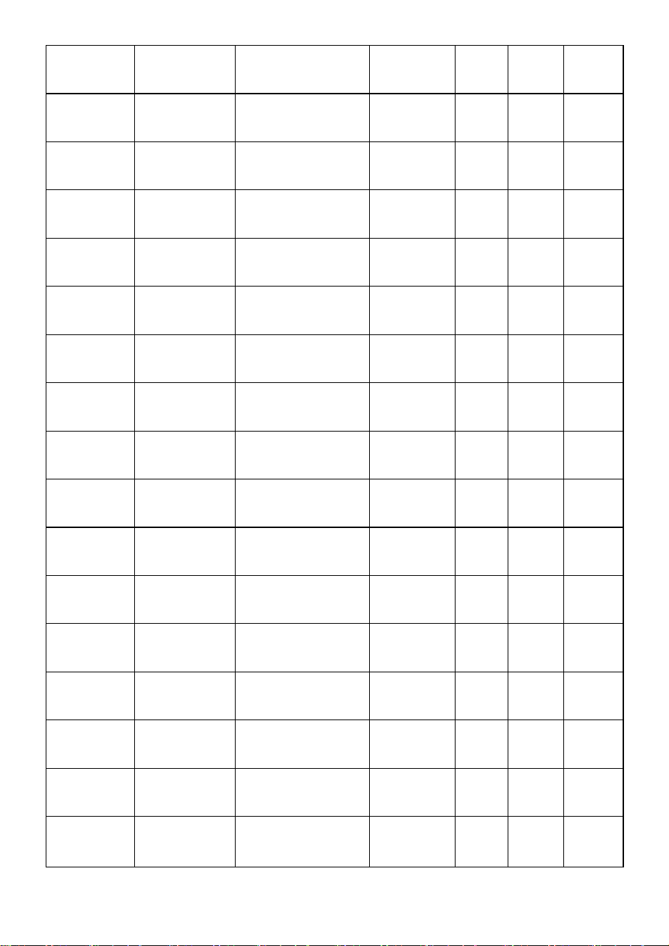
- 4 -
HET-
24*72-L
520/420lbs
610*1829*914
whole
√
√
×
HET-
24*24-3L
700/540lbs
610*610*660
whole
√
√
×
HETG-
24*12
300/200lbs
610*305*954.6
separated
√
×
√
HETG-
24*18
370/270lbs
610*457*954.6
separated
×
×
√
HETG-
24*24
400/300lbs
610*610*954.6
separated
×
×
√
HETG-
24*30
400/300lbs
610*762*954.6
separated
×
×
√
HETG-
24*48
460/340lbs
610*1219*954.6
whole
×
×
√
HETG-
30*12
300/220lbs
762*305*954.6
separated
×
×
√
HETG-
30*36
470/350lbs
762*914*954.6
whole
×
×
√
HETG-
30*48
500/370lbs
762*1219*954.6
whole
×
×
√
HETG-
30*60
520/390lbs
762*1524*954.6
whole
×
×
√
HETG-
24*15-L
300/200lbs
610*381*1005.6
separated
√
×
√
HETG-
24*24-L
400/300lbs
610*610*1005.6
separated
√
×
√
HETG-
24*30-L
400/300lbs
610*762*1005.6
separated
√
×
√
HETG-
24*36-L
430/320lbs
610*914*1005.6
whole
√
×
√
HETG-
24*48-L
460/340lbs
610*1219*1005.6
whole
√
×
√
HETG-
24*60-L
480/360lbs
610*1524*1005.6
whole
√
×
√
- 5 -
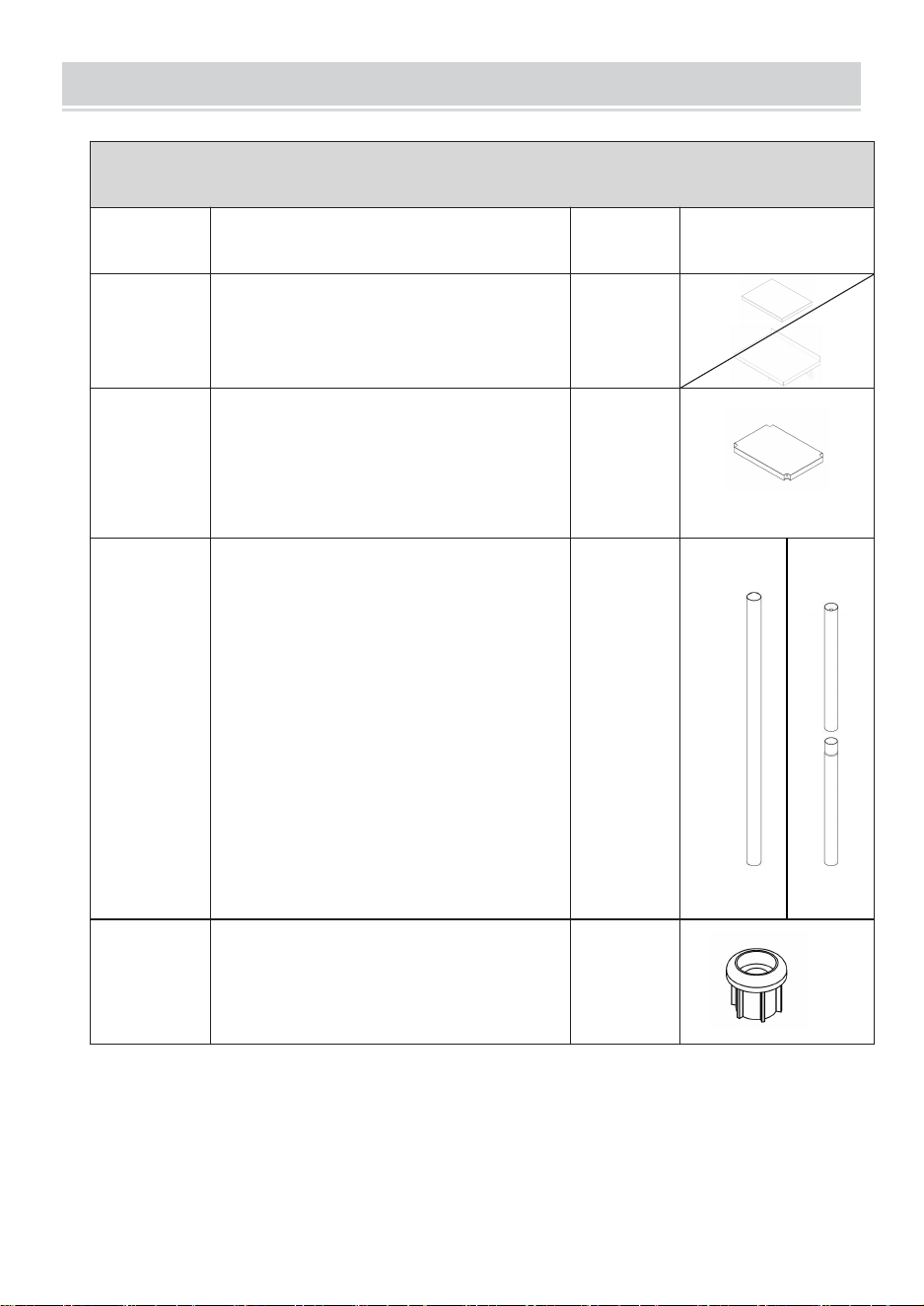
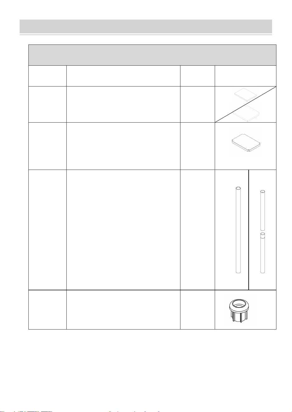
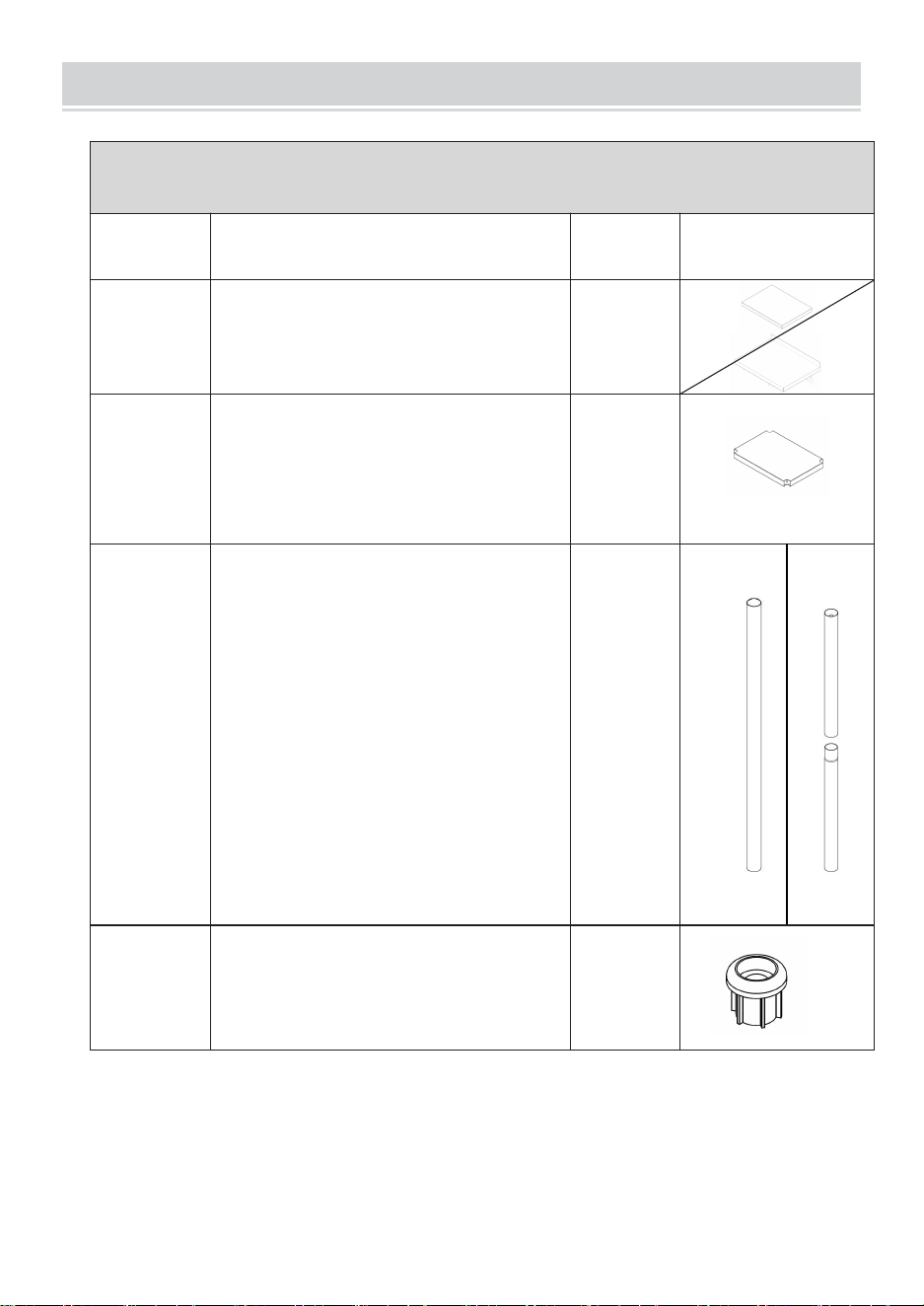
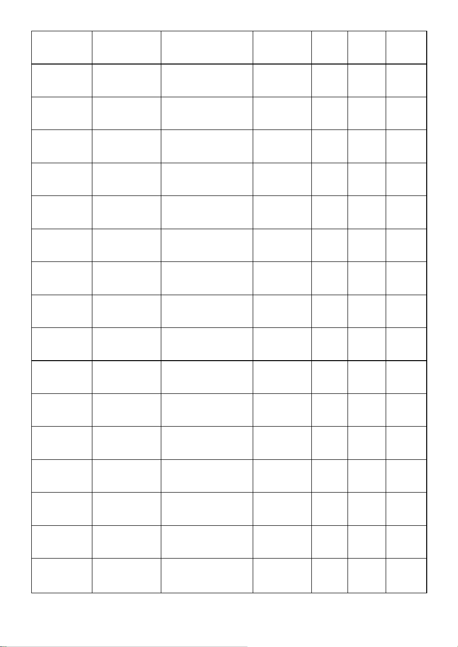
PACKING LIST
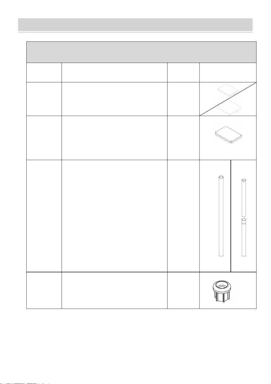
Note: Parts details 1 through 8 are available for all models.
Item
Part Name
QTY
Picture
1
Panel
1 PCS
2
Shelves
1 PCS
3
Table legs ( whole / separated)
Tip
:
legs various to refer the Product
Parameters table
4 PCS
(4PCS/4P
CS)
4
Mounting sleeves
4 PCS
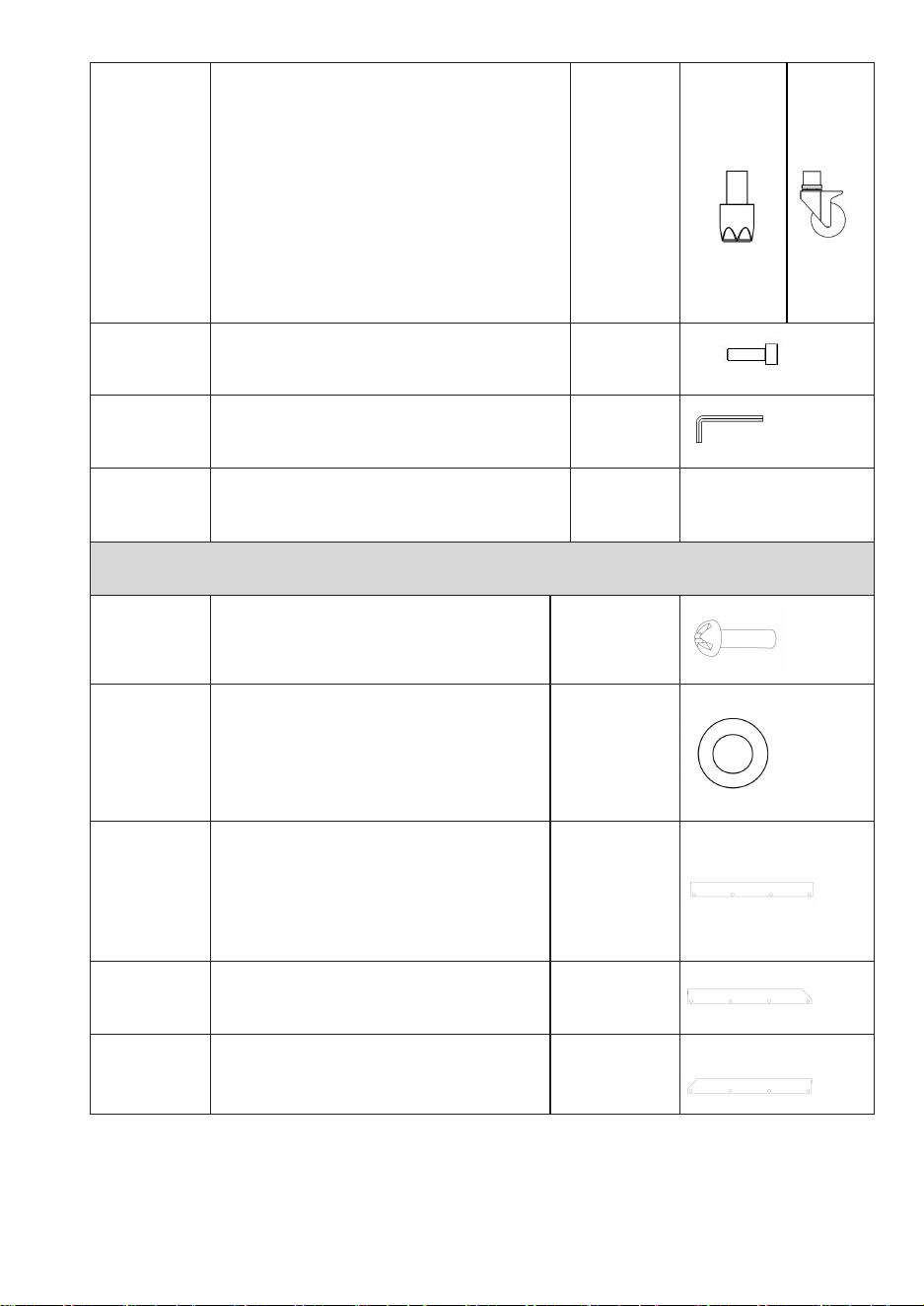
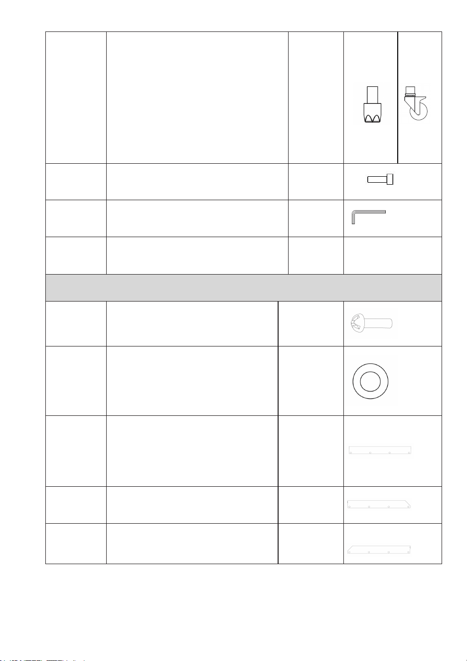
- 6 -
5
Support feet
(
3-inch universal wheels
(2 with brakes)
)
Tip
:
various to refer the Product
Parameters
table
4 PCS
6
M6 Allen socket screws
8PCS
7
hex key
1PCS
8
User Manual
1PCS
Note: Parts details 9 through 13 are only available for HT-24 *24-3L
9
M5 screws
12PCS
10
φ5 gasket
12PCS
11
flapper-1
1PCS
12
flapper-2
1PCS
13
flapper-3
1PCS

- 7 -
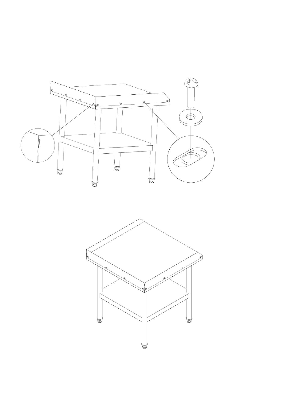
ASSEMBLY STEP
This is the original instruction, please read all manual instructions carefully before
operating.VEVOR reserves clear interpretation of our user manual. The
appearance of the product shall be subject to the product you received. Please
forgive us that we won't inform you again if there is any| technology or software
updates on our product.
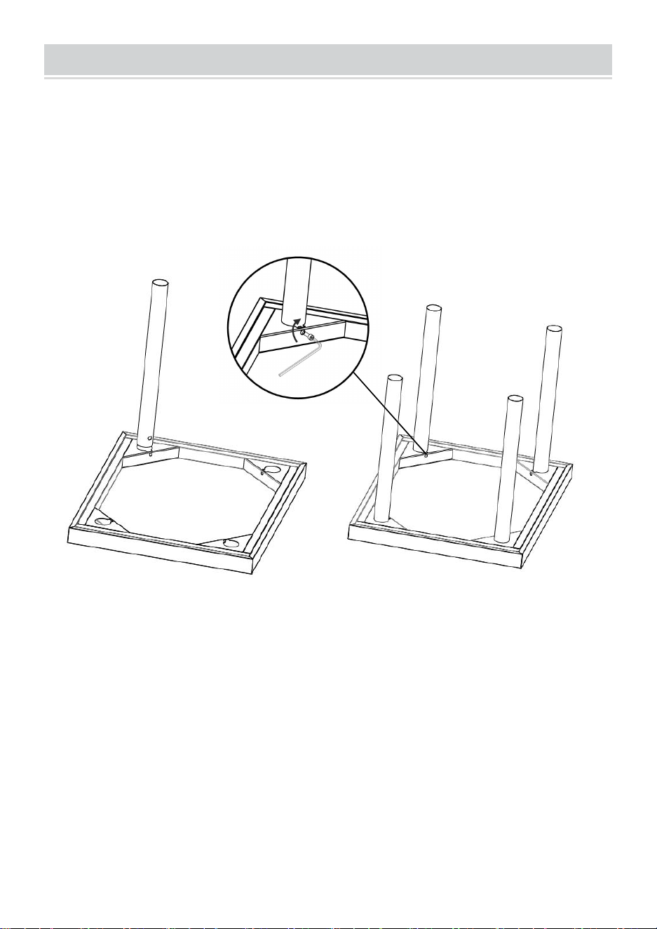
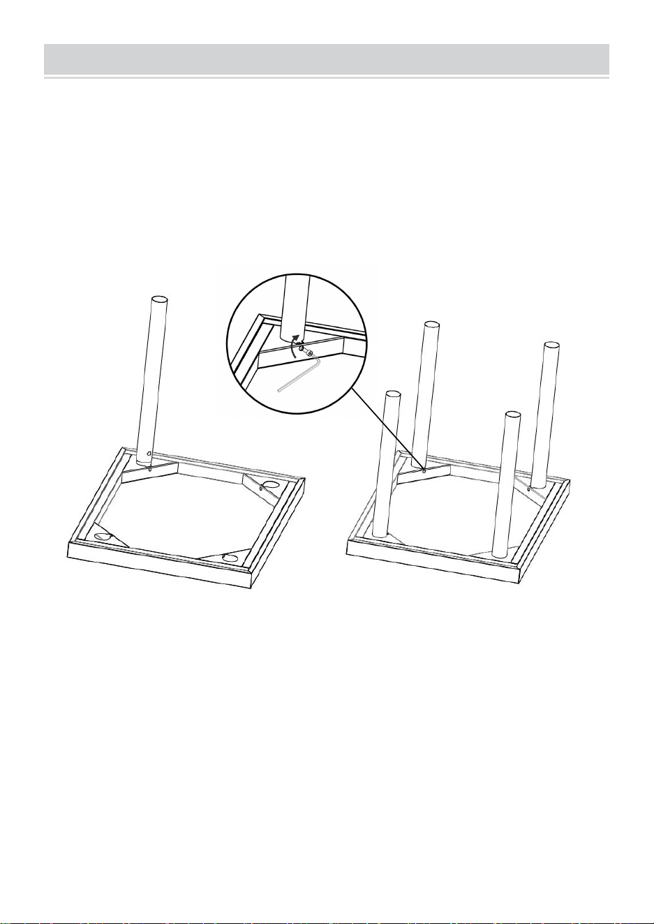
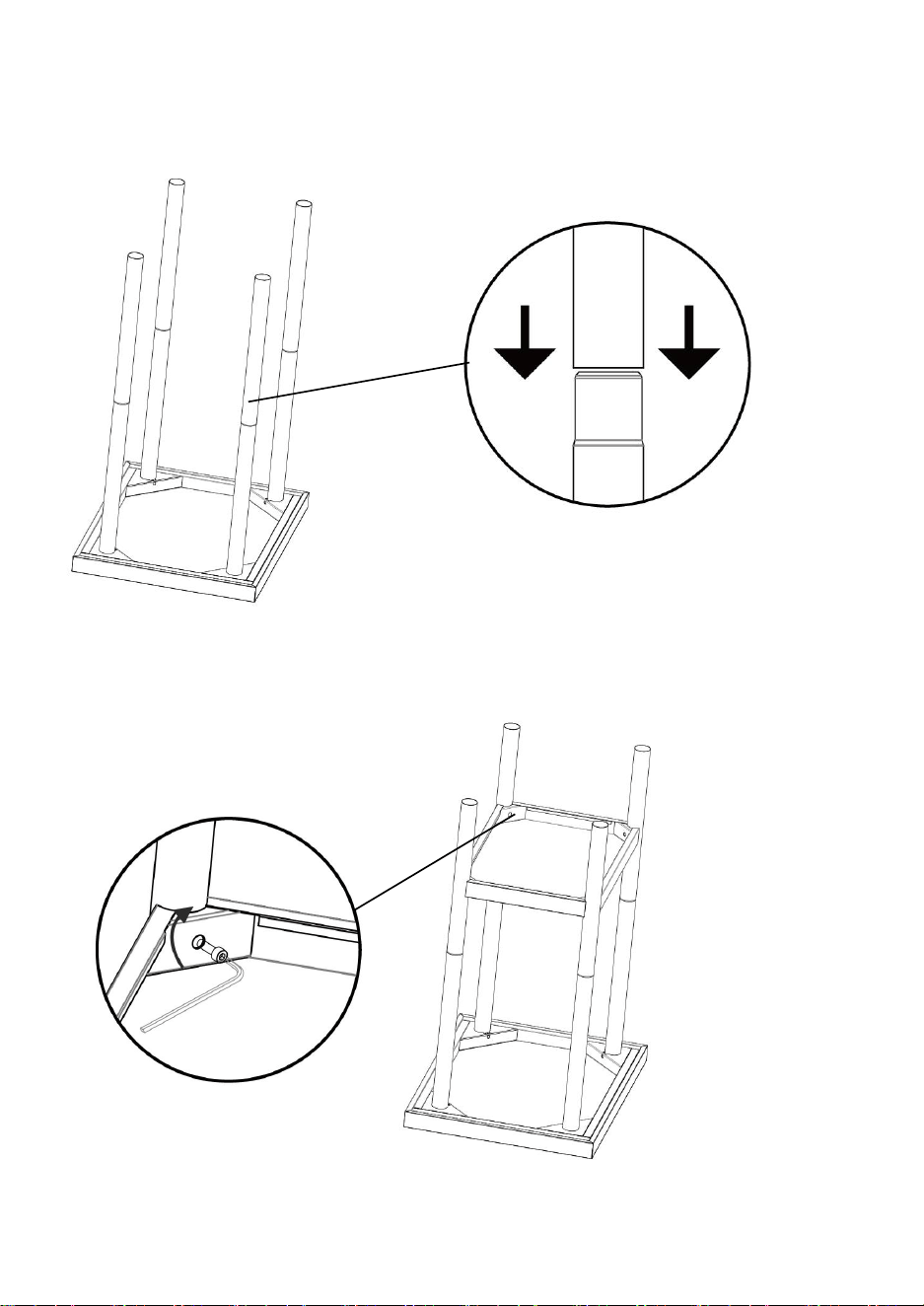
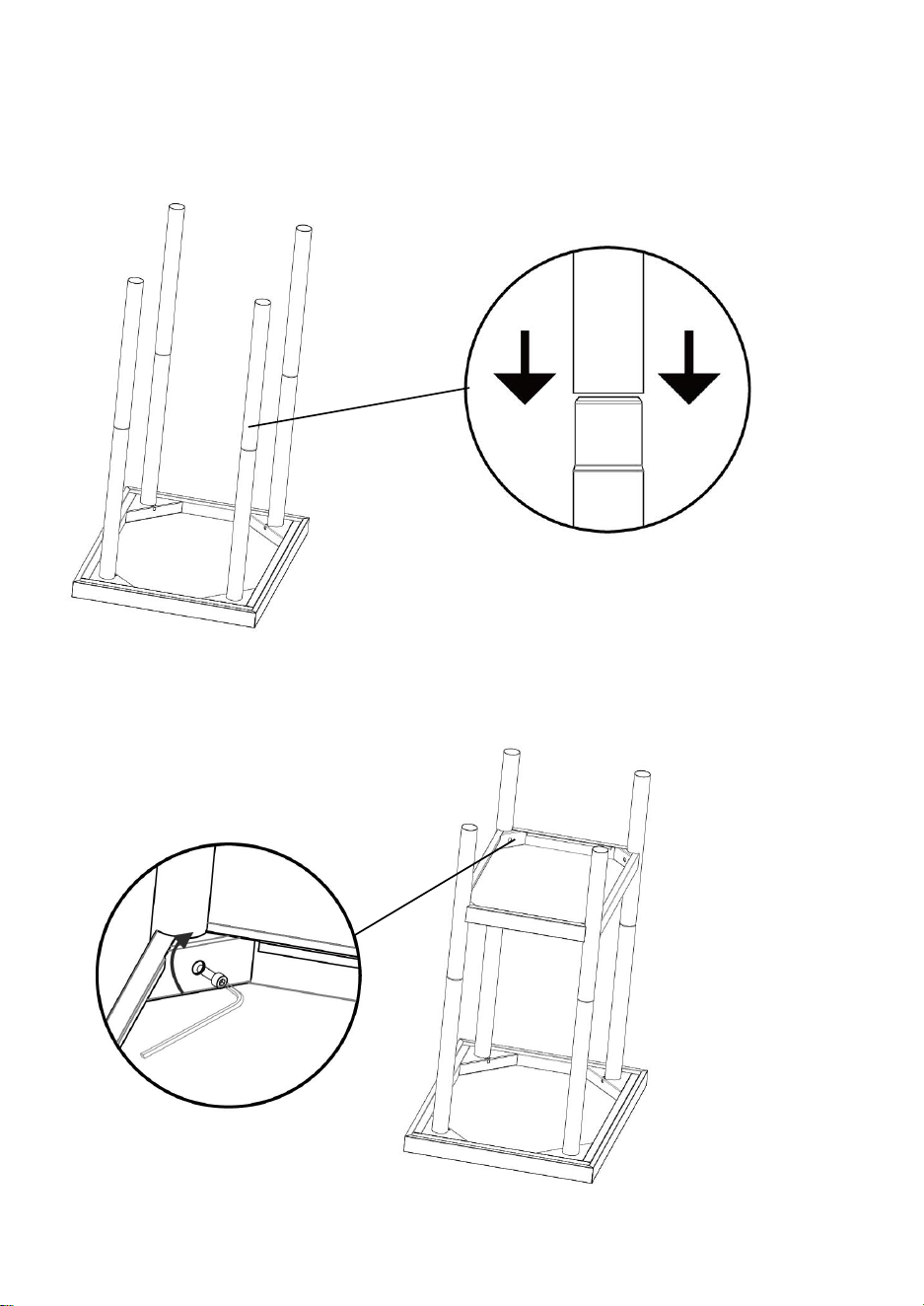
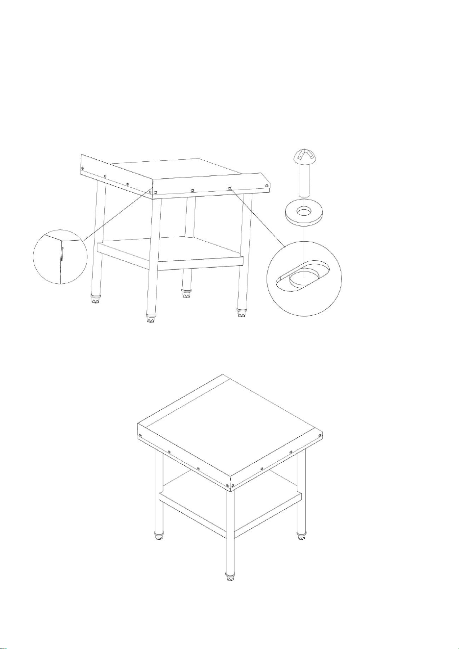
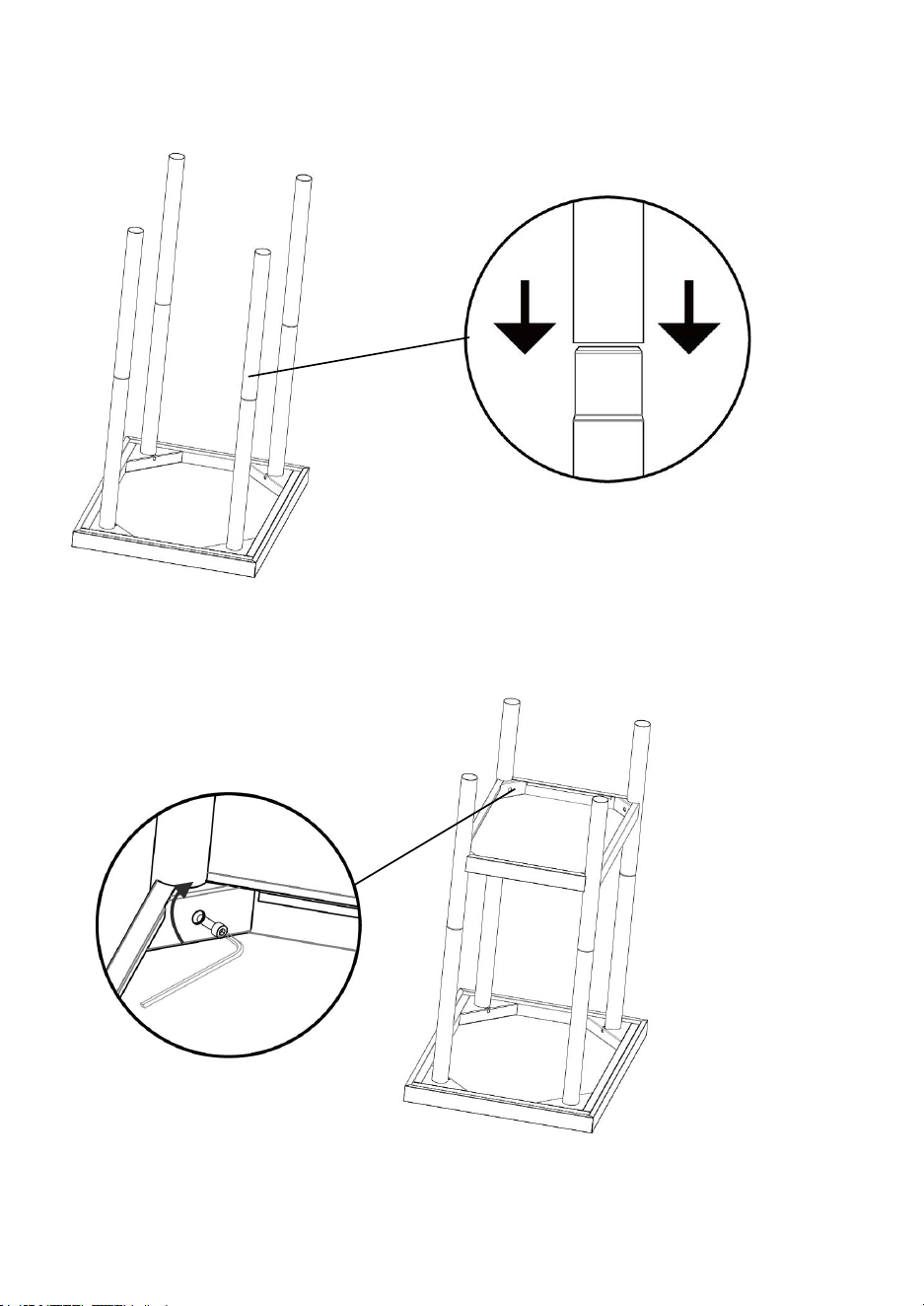
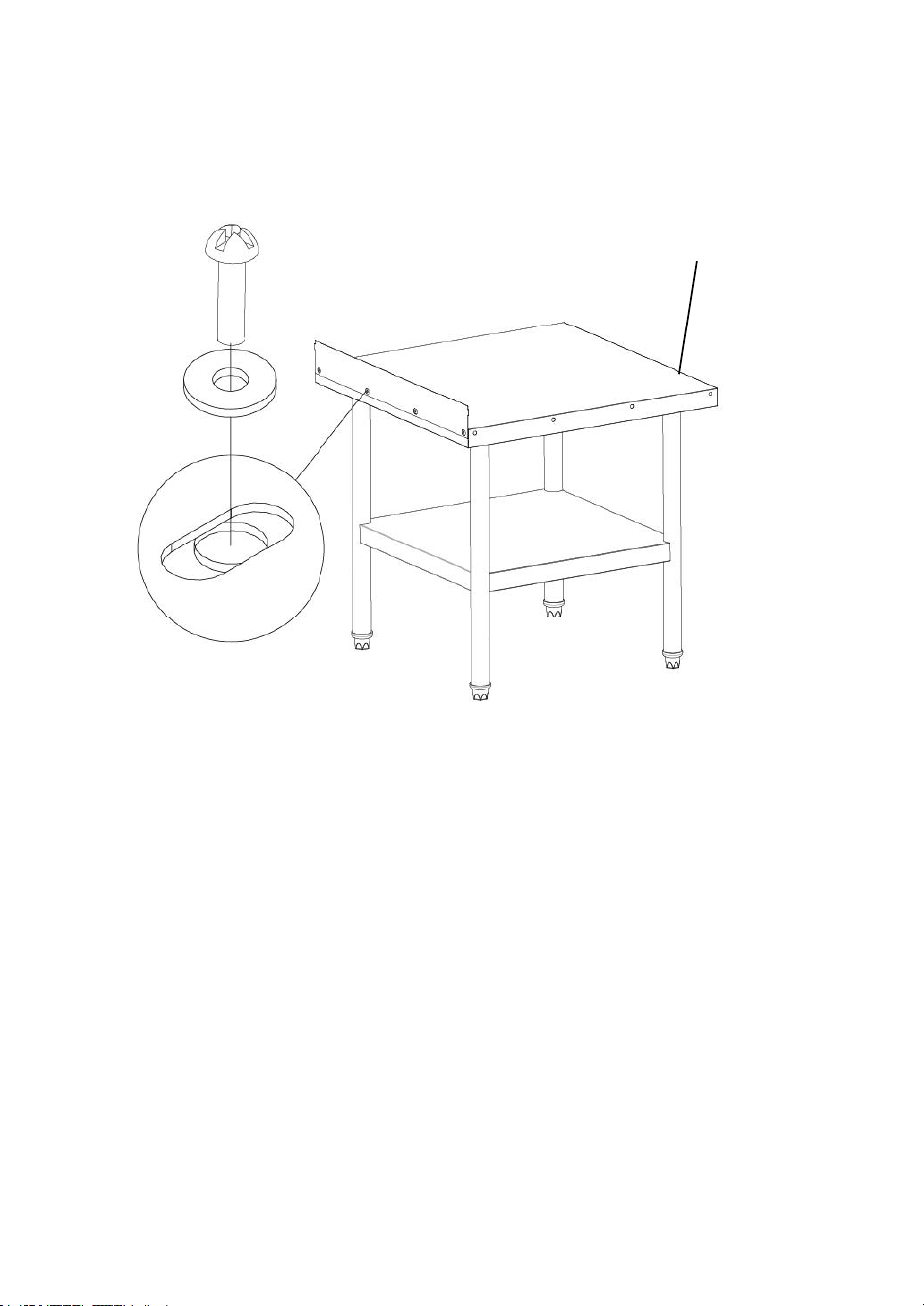
1.Place the Top board mounting hole facing upwards, install the round pipe into
the hole, fix it with M6 socket screws and have a torque greater than or equal to
25N.m

- 8 -
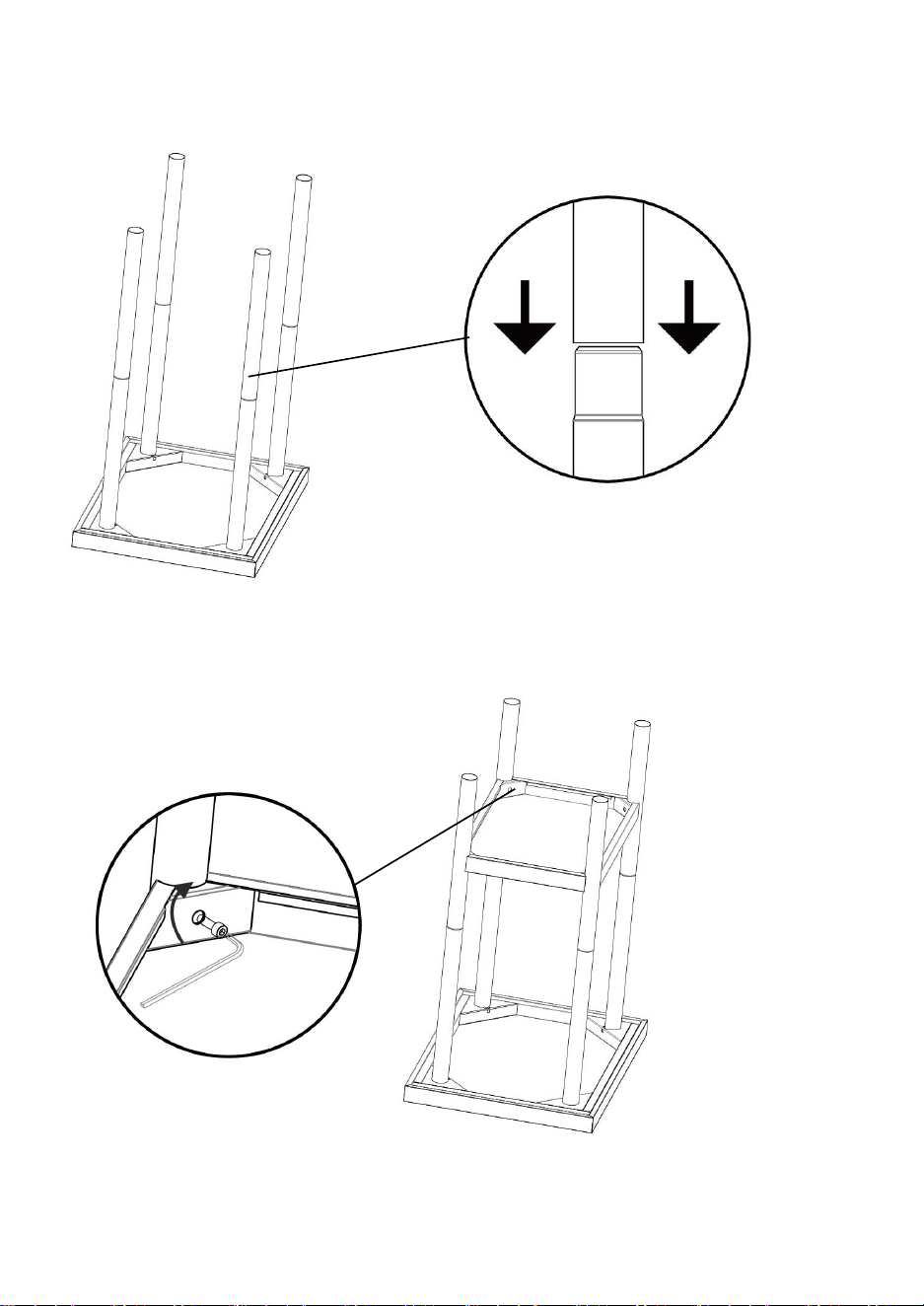
2. Some models distinguish the model of the upper and lower support pipes, and
the upper and lower support pipes need to be covered
Note: This step can be omitted for products with whole legs;
3.Install the partition according to the height of the hole position you need, fix the
mounting hole with M6 socket socket screws and the torque is greater than or equal
to 25N.m
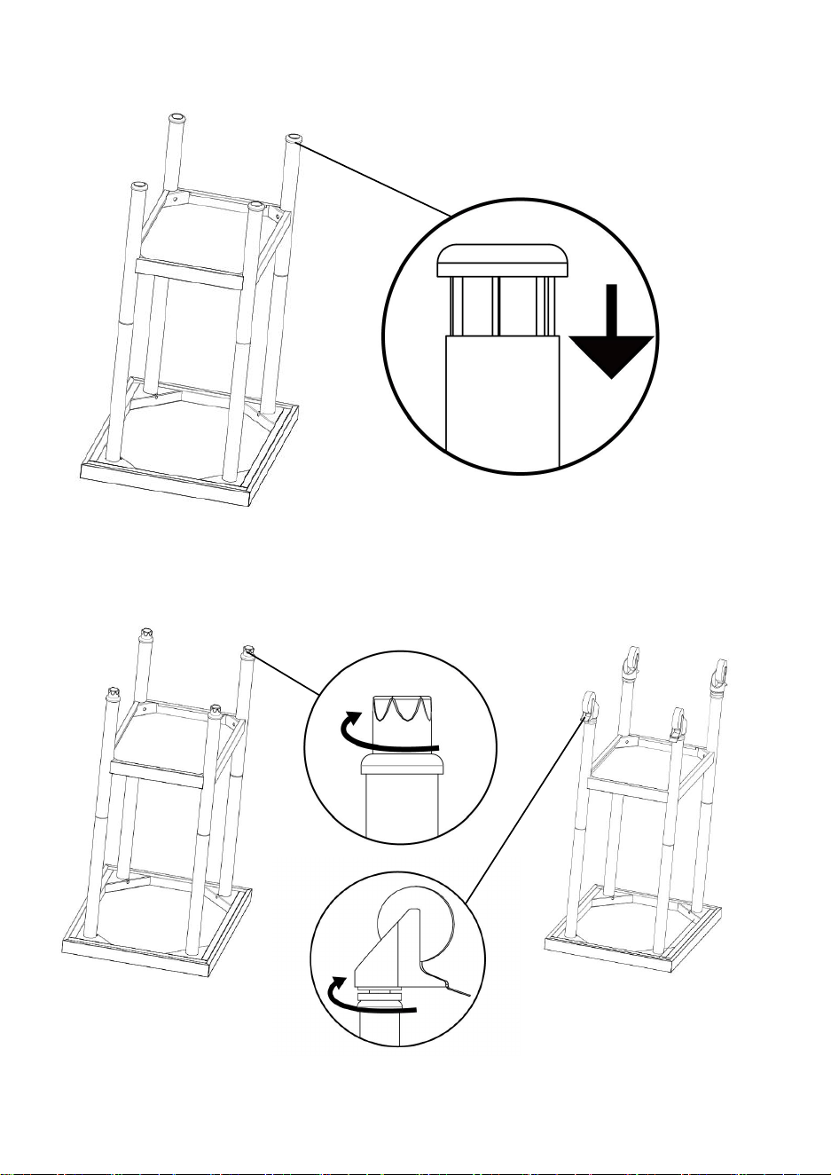
- 9 -
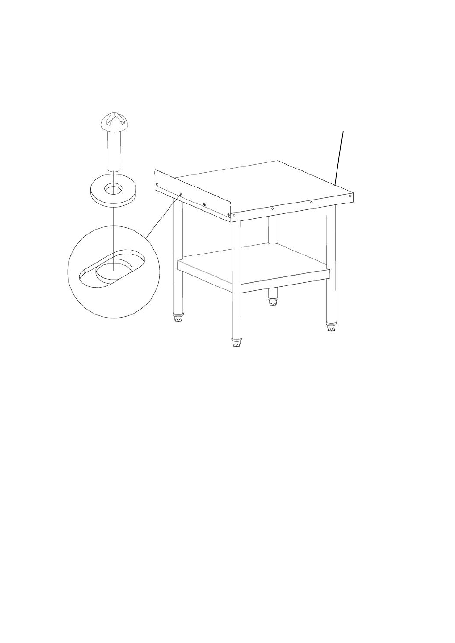
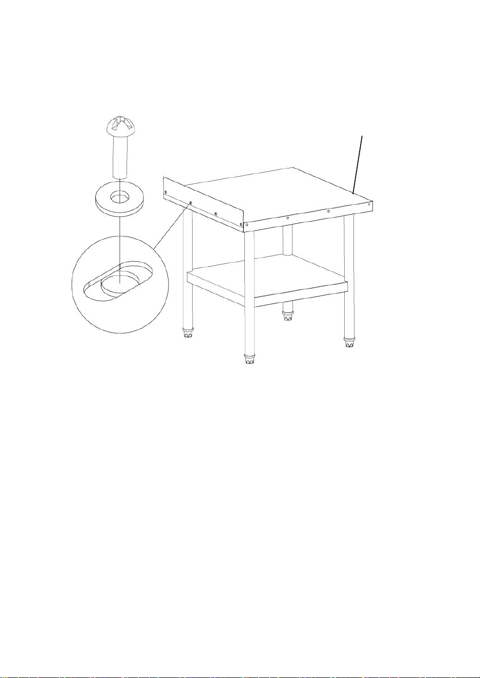
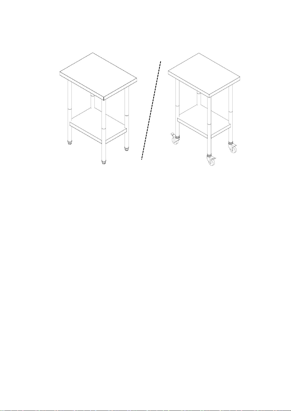
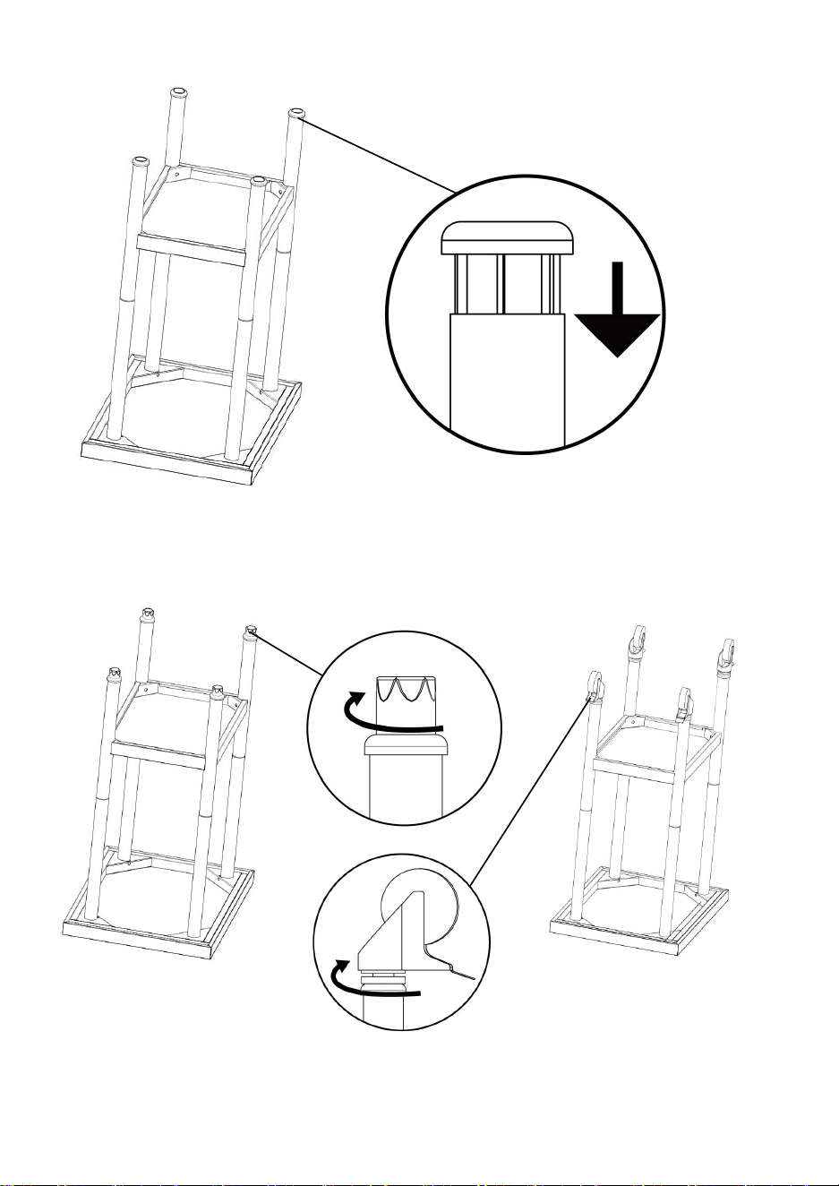
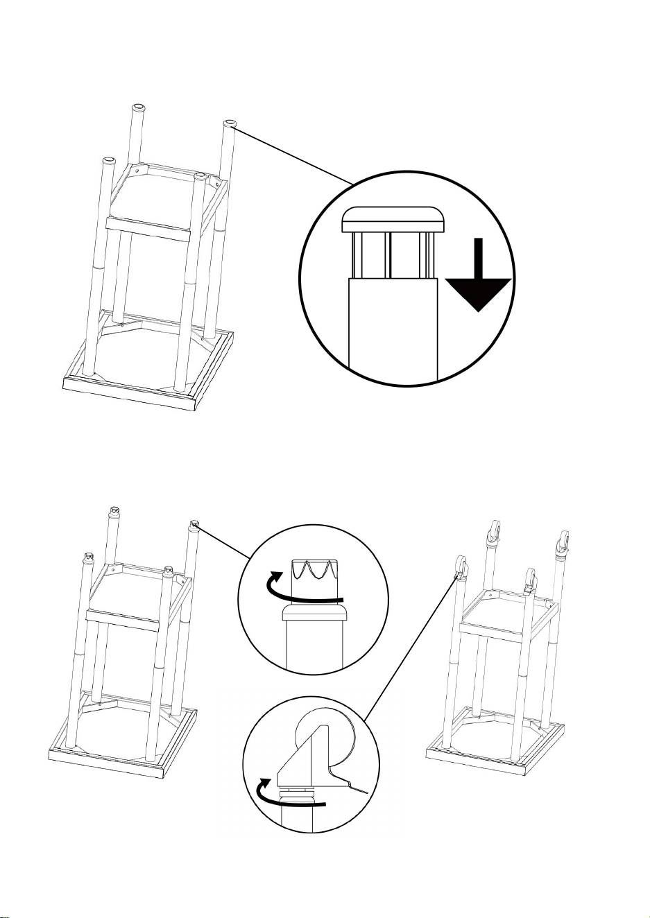
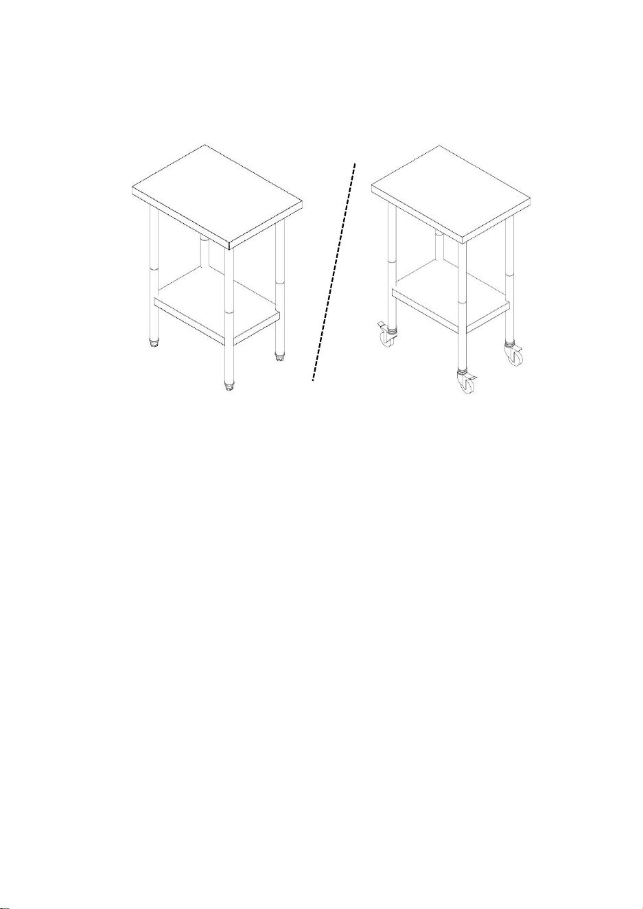
4.Install the casing knock into the round pipe。
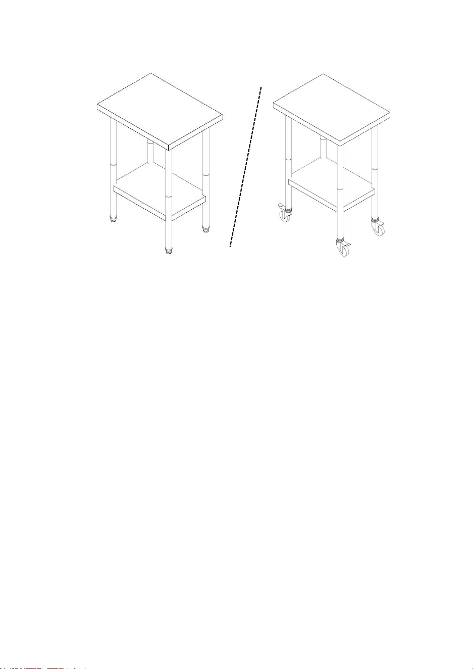
5.Install the support feet or wheels

- 10 -
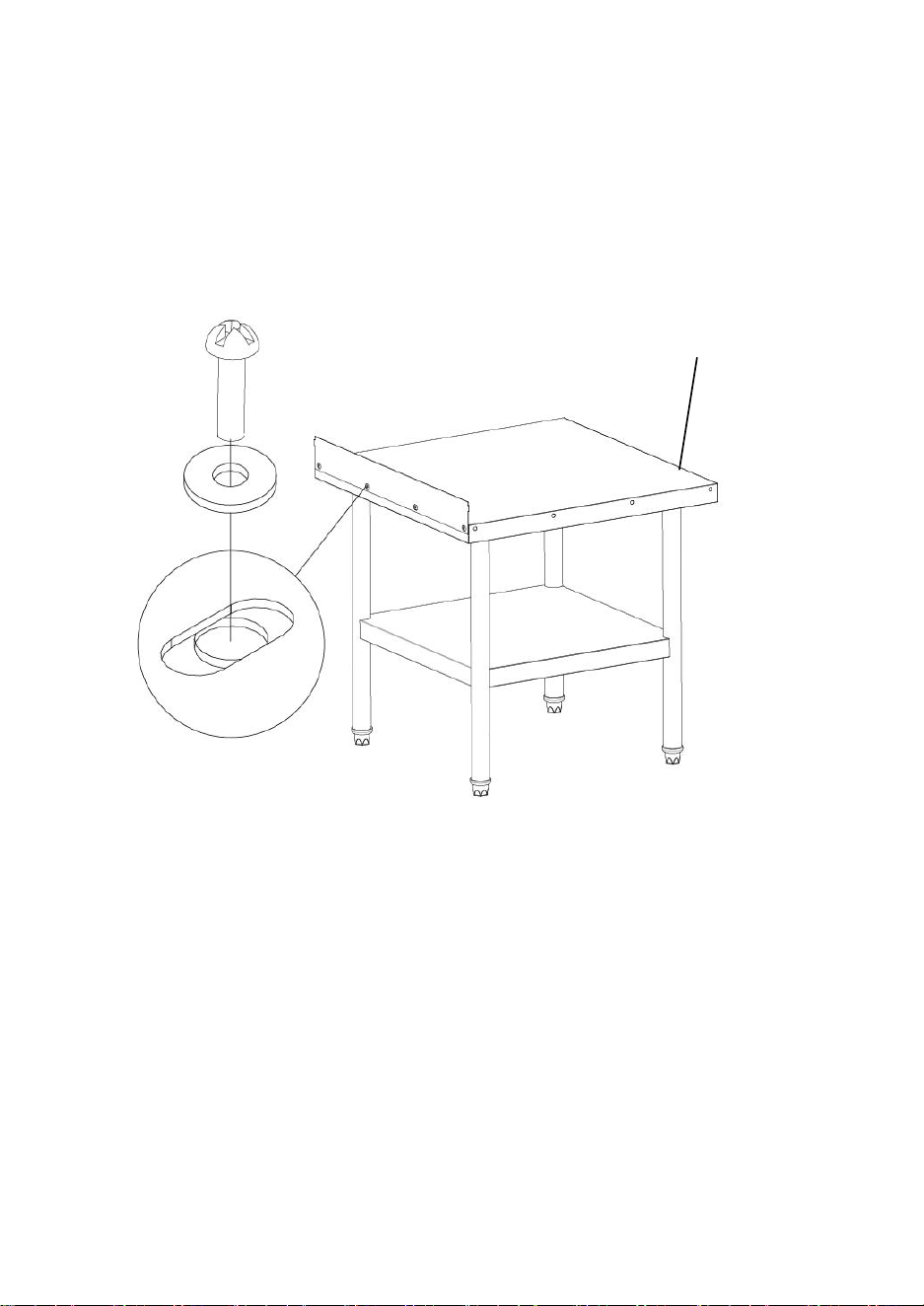
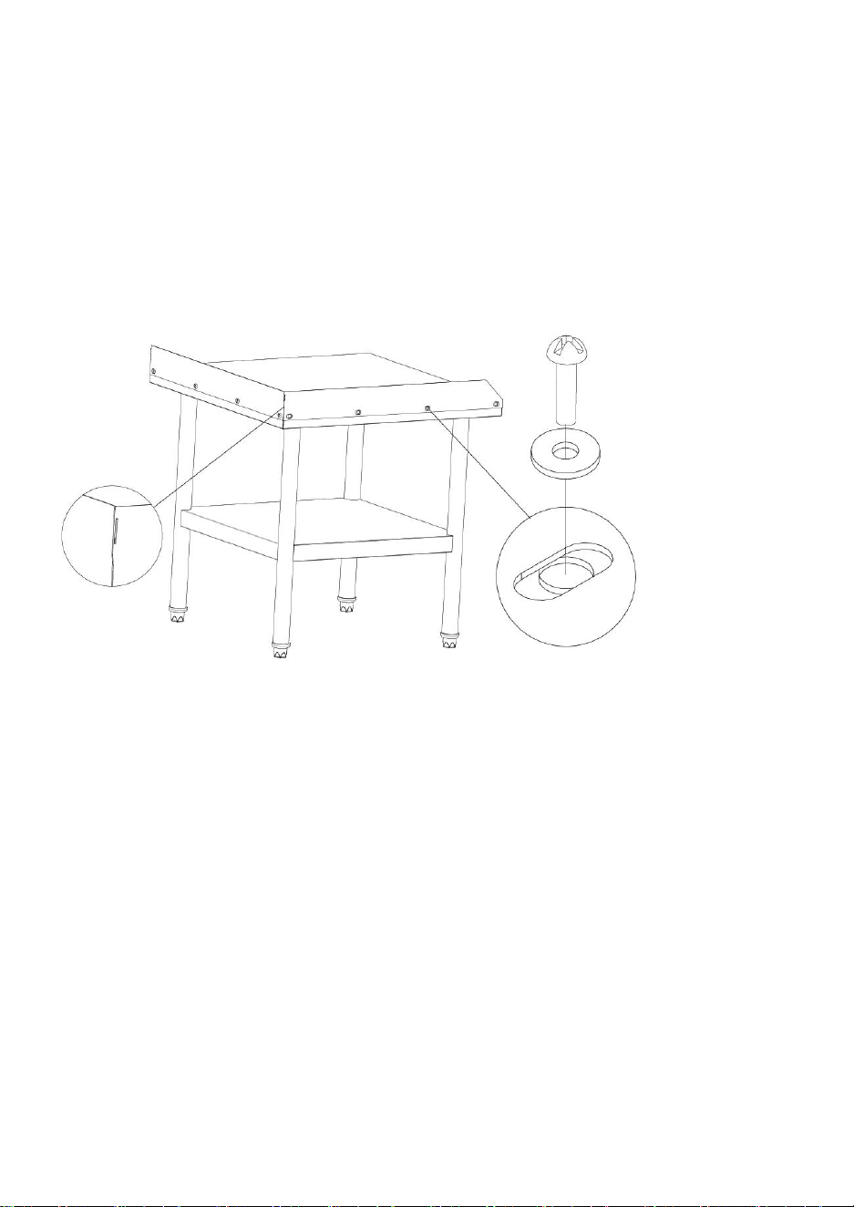
6. After completed the installation, turn the workbench over and adjust the height
of the four support feet (or wheels) to ensure that the four feet are close to the
ground and the workbench is stable
Note: If the workbench does not need to be moved. Please hold the brakes on the
wheels to ensure that the table does not move.
The workbench has a maximum weight limit, please be careful not to exceed the
maximum weight
- 11 -
Note:Below installation steps only for HET-24*24-3L
1. Install the flapper-1 on the workbench in the correct orientation (please refer to
the logo direction), then tighten it with M5*12 screws and M5 flat pads, and fasten
the baffle-1 on the workbench.
Logo
- 12 -
2.
The baffle-2 and the baffle-1 are buckled and correctly placed on the
workbench, and then fastened with M5*12 screws and M5 flat pads, and the
baffle plate 1 is fastened on the workbench. (The installation steps of Bezel-
3 are similar, please refer to this step)
3. Finished product drawing HET-24*24-3L

- 15 -
Manufacturer: Shanghaimuxinmuyeyouxiangongsi
Address: Shuangchenglu 803nong11hao1602A-1609shi, baoshanqu,
shanghai 200000 CN.
Imported to AUS: SIHAO PTY LTD. 1 ROKEVA STREETEASTWOOD
NSW 2122 Australia
Imported to USA: Sanven Technology Ltd. Suite 250, 9166 Anaheim
Place, Rancho Cucamonga, CA 91730
REP
EC
E-CrossStu GmbH
Mainzer Landstr.69, 60329 Frankfurt am Main.
REP
UK
YH CONSULTING LIMITED.
C/O YH Consulting Limited Office 147, Centurion
House, London Road, Staines-upon-Thames, Surrey,
TW18 4AX


Techniczny Certyfikat wsparcia i e-gwarancji www . wevor . com/wsparcie
STOŁ WARSZTATOWY
INSTRUKCJA OBSŁUGI
We continue to be committed to provide you tools with competitive price.
"Save Half", "Half Price" or any other similar expressions used by us only represents an
estimate of savings you might benefit from buying certain tools with us compared to the
major top brands and does not necessarily mean to cover all categories of tools offered by
us. You are kindly reminded to verify carefully when you are placing an order with us if you
are actually saving half in comparison with the top major brands.

- 1 -
Uwaga: to użytkownik podręcznik Jest
stosuje się
do the bawełna cukierek
maszyny.
Proszę Czytać To ostrożnie zanim używać.
Have product questions? Need technical support? Please feel free to
contact us:
Technical Support and E-Warranty Certificate
www. vevor. com/support
NEED HELP? CONTACT US!
This is the original instruction, please read all manual instructions
carefully before operating. VEVOR reserves a clear interpretation of our
user manual. The appearance of the product shall be subject to the
product you received. Please forgive us that we won't inform you again if
there are any technology or software updates on our product.
HET-24*18 HET-24*30 HET-24*36
HET-24*48 HET-24* 60 HET-24*72
HET-30*48 HET-30*60 HET-30*72
HET-24*30-L HET-24*36-L HET-24*48-L
HET-24*60-L HET-24*72-L
HET-24*24-3L
HETG-24*12 HETG-24*18 HETG-24*24
HETG-24*30 HETG-24*48 HETG-30*12
HETG-30*36 HETG-30*48 HETG-30*60
HETG-24*15-L HETG-24*24-L HETG-24*30-L
HETG-24*36-L HETG-24*48-L HETG-24*60-L
WORKBENCH

- 2 -
SAFETY INSTRUCTIONS
OSTRZEŻENIE:
Przeczytaj ten materiał przed użyciem tego produktu. Niezastosowanie
się do tego może spowodować poważne obrażenia.
Środki ostrożności podczas montażu
1. Montaż wyłącznie zgodnie z niniejszą instrukcją. Nieprawidłowy montaż
może stworzyć zagrożenie.
2. Utrzymuj miejsce zbiórki w czystości i dobrze oświetlone.
3. Podczas montażu trzymaj osoby postronne z dala od obszaru.
4. Nie należy montować, gdy jest się zmęczonym lub pod wpływem alkoholu,
narkotyków lub leków.
5. Możliwości produktu dotyczą wyłącznie produktów prawidłowo i całkowicie
zmontowanych.
6. Dodatkowe informacje dotyczące części wymienionych na kolejnych
stronach można znaleźć w schemacie montażu w niniejszej instrukcji.
Rozpakuj i oddziel wszystkie części w czystym miejscu pracy.
Stosuj środki ostrożności
1. Używanie produktów cięższych niż wskazane wagi znamionowe może
spowodować niestabilność i możliwe obrażenia.
2. Mocowania należy zamocować zgodnie z instrukcją montażu.
Nieprawidłowa instalacja może spowodować uszkodzenie lub poważne
obrażenia ciała.
3. Upewnij się, że powierzchnia nośna bezpiecznie utrzyma łączny ciężar
sprzętu i całego podłączonego sprzętu i komponentów.
4. Użyj dostarczonych śrub montażowych i NIE DOKRĘCAJ ich zbyt mocno.
5. Ten produkt zawiera małe elementy, które w przypadku połknięcia mogą
spowodować ryzyko zadławienia. Trzymaj te przedmioty z dala od dzieci.
6. Ten produkt jest przeznaczony wyłącznie do użytku w pomieszczeniach
zamkniętych. Używanie tego produktu na zewnątrz może prowadzić do
awarii produktu i obrażeń ciała.
RATOWAĆ TE INSTRUKCJE

- 3 -
PRODUCT PARAMETERS
Przedmiot
nr.
Maksymalna
nośność
(Deska
górna/deska
klapowa )
Rozmiar produktu
(mm)
Nogi do
stołu
(całe/oddz
ielne)
Desk
a
tylna
Stopy
podp
orow
e
Koło
HET-24*18
370/270
funtów
610*457*864
rozdzielon
y
×
√
×
HET-24*30
400/300
funtów
610*762*864
rozdzielon
y
×
√
×
HET-24*36
430/320
funtów
610*914*864
cały
×
√
×
HET-24*48
460/340
funtów
610*1219*864
cały
×
√
×
HET-24*60
480/360
funtów
610*1524*864
cały
×
√
×
HET-24*72
500/380
funtów
610*1829*864
cały
×
√
×
HET-30*48
500/380
funtów
762*1219*864
cały
×
√
×
HET-30*60
520/390
funtów
762*1524*864
cały
×
√
×
HET-30*72
520/400
funtów
762*1829*864
cały
×
√
×
HET-
24*30-L
420/320
funtów
610*762*914
rozdzielon
y
√
√
×
HET-
24*36-L
450/350
funtów
610*914*914
cały
√
√
×
HET-
24*48-L
480/380
funtów
610*1219*914
cały
√
√
×
HET-
24*60-L
500/400
funtów
610*1524*914
cały
√
√
×
- 4 -
HET-
24*72-L
520/420
funtów
610*1829*914
cały
√
√
×
HET-
24*24-3L
700/540
funtów
610*610*660
cały
√
√
×
HETG-
24*12
300/200
funtów
610*305*954,6
rozdzielon
y
√
×
√
HETG-
24*18
370/270
funtów
610*457*954,6
rozdzielon
y
×
×
√
HETG-
24*24
400/300
funtów
610*610*954,6
rozdzielon
y
×
×
√
HETG-
24*30
400/300
funtów
610*762*954,6
rozdzielon
y
×
×
√
HETG-
24*48
460/340
funtów
610*1219*954,6
cały
×
×
√
HETG-
30*12
300/220
funtów
762*305*954,6
rozdzielon
y
×
×
√
HETG-
30*36
470/350
funtów
762*914*954,6
cały
×
×
√
HETG-
30*48
500/370
funtów
762*1219*954,6
cały
×
×
√
HETG-
30*60
520/390
funtów
762*1524*954,6
cały
×
×
√
HETG-
24*15-L
300/200
funtów
610*381*1005,6
rozdzielon
y
√
×
√
HETG-
24*24-L
400/300
funtów
610*610*1005,6
rozdzielon
y
√
×
√
HETG-
24*30-L
400/300
funtów
610*762*1005,6
rozdzielon
y
√
×
√
HETG-
24*36-L
430/320
funtów
610*914*1005,6
cały
√
×
√
HETG-
24*48-L
460/340
funtów
610*1219*1005,6
cały
√
×
√
HETG-
24*60-L
480/360
funtów
610*1524*1005,6
cały
√
×
√
- 5 -
PACKING LIST
Uwaga: Szczegóły części od 1 do 8 są dostępne dla wszystkich modeli .
Przedmiot
Część Nazwa
ILOŚĆ
Zdjęcie
1
Płyta
1 szt
2
Półki
1 szt
3
Nogi do stołu (całe/oddzielne)
Wskazówka: różne nogi, patrz tabela
parametrów produktu
4 szt
(4
SZTUK/4
SZTUK)
4
Tulejki montażowe
4 szt

- 6 -
5
Stopy podporowe
(
3-calowe uniwersalne koła
(2 z hamulcami)
)
Wskazówka : różne informacje
dotyczące parametrów produktu
tabela
4 szt
6
M6 Śruby imbusowe
8 szt
7
klucz sześciokątny
1 szt
8
Instrukcja obsługi
1 szt
Uwaga: Dane części od 9 do 13 są dostępne tylko dla HT-24 *24-3L
9
Śruby M5
12szt
10
Uszczelka φ5
12szt
11
klapa -1
1 szt
12
klapa -2
1 szt
13
klapa -3
1 szt
- 7 -
ASSEMBLY STEP
To jest oryginalna instrukcja. Przed przystąpieniem do obsługi prosimy o dokładne
zapoznanie się ze wszystkimi instrukcjami. VEVOR zastrzega sobie jasną
interpretację naszej instrukcji obsługi. Wygląd produktu zależy od produktu, który
otrzymałeś. Proszę, wybacz nam, że nie będziemy Cię ponownie informować, jeśli
jakieś się pojawią aktualizacje technologii lub oprogramowania naszego produktu.
1. Umieść otwór montażowy górnej płyty skierowany do góry, zainstaluj okrągłą
rurę w otworze, przykręć ją śrubami z łbem gniazdowym M6 i dokręć momentem
obrotowym większym lub równym 25 N.m
- 8 -
2. W niektórych modelach rozróżnia się model górnej i dolnej rury nośnej, a
górne i dolne rury nośne wymagają zakrycia
Uwaga: ten krok można pominąć w przypadku produktów z całymi nogami ;
3. Zamontuj przegrodę zgodnie z potrzebną wysokością otworu, przymocuj otwór
montażowy za pomocą śrub z łbem gniazdowym M6, a moment obrotowy jest
większy lub równy 25 N.m
4. Zamontuj wbijaną obudowę w okrągłą rurę.

- 9 -
5 . Zamontuj stopy podporowe lub kółka
6. Po zakończeniu montażu obróć stół warsztatowy i wyreguluj wysokość czterech

- 10 -
nóżek podporowych (lub kółek ), aby mieć pewność, że cztery nóżki znajdują się
blisko podłoża, a stół warsztatowy jest stabilny
Uwaga: Jeśli stół warsztatowy nie wymaga przenoszenia. Proszę przytrzymać
hamulce kół, aby mieć pewność, że stół się nie przesunie .
Stół warsztatowy ma ograniczenie maksymalnego ciężaru, należy uważać, aby go
nie przekroczyć
Uwaga : Poniższe kroki instalacyjne dotyczą tylko HET-
- 11 -
24*24-3L
1. Zamontuj klapę-1 na stole warsztatowym w prawidłowej orientacji (patrz
kierunek logo), następnie dokręć ją śrubami M5*12 i płaskimi podkładkami M5 i
przymocuj przegrodę-1 na stole warsztatowym.
Logo

- 12 -
2 .
Baffle-2 i Baffle-1 są zapinane i prawidłowo umieszczane na stole
warsztatowym, a następnie mocowane za pomocą śrub M5*12 i płaskich
podkładek M5, a płyta dopalająca 1 jest mocowana na stole warsztatowym.
(Etapy instalacji Bezel-3 są podobne, zapoznaj się z tym krokiem)
3. Rysunek gotowego produktu HET-24*24-3L
- 15 -
Producent: Shanghaimuxinmuyeyouxiangongsi
Adres: Shuangchenglu 803nong11hao1602A-1609shi, baoshanqu,
szanghaj 200000 CN.
Import do AUS: SIHAO PTY LTD. 1 ROKEVA STREETEASTWOOD NSW
2122 Australia
Import do USA: Sanven Technology Ltd. Suite 250, 9166 Anaheim Place,
Rancho Cucamonga, CA 91730
REP
EC
E-CrossStu GmbH
Mainzer Landstr.69, 60329 Frankfurt am Main.
REP
UK
YH CONSULTING LIMITED.
C/O YH Consulting Limited Office 147, Centurion
House, London Road, Staines-upon-Thames, Surrey,
TW18 4AX


Technisch Support- und E-Garantiezertifikat www . vevor . com/support
WERKBANK
BENUTZERHANDBUCH
We continue to be committed to provide you tools with competitive price.
"Save Half", "Half Price" or any other similar expressions used by us only represents an
estimate of savings you might benefit from buying certain tools with us compared to the
major top brands and does not necessarily mean to cover all categories of tools offered by
us. You are kindly reminded to verify carefully when you are placing an order with us if you
are actually saving half in comparison with the top major brands.
- 1 -
Hinweis: Dies Benutzer Handbuch Ist
anwendbar
auf Die Baumwolle Süßigkeiten
Maschinen.
Bitte lesen Es sorgfältig Vor verwenden.
Have product questions? Need technical support? Please feel free to
contact us:
Technical Support and E-Warranty Certificate
www. vevor. com/support
NEED HELP? CONTACT US!
This is the original instruction, please read all manual instructions
carefully before operating. VEVOR reserves a clear interpretation of our
user manual. The appearance of the product shall be subject to the
product you received. Please forgive us that we won't inform you again if
there are any technology or software updates on our product.
HET-24*18 HET-24*30 HET-24*36
HET-24*48 HET-24* 60 HET-24*72
HET-30*48 HET-30*60 HET-30*72
HET-24*30-L HET-24*36-L HET-24*48-L
HET-24*60-L HET-24*72-L
HET-24*24-3L
HETG-24*12 HETG-24*18 HETG-24*24
HETG-24*30 HETG-24*48 HETG-30*12
HETG-30*36 HETG-30*48 HETG-30*60
HETG-24*15-L HETG-24*24-L HETG-24*30-L
HETG-24*36-L HETG-24*48-L HETG-24*60-L
WORKBENCH

- 2 -
SAFETY INSTRUCTIONS
WARNUNG:
Lesen Sie dieses Material, bevor Sie dieses Produkt verwenden.
Andernfalls kann es zu schweren Verletzungen kommen.
Vorsichtsmaßnahmen bei der Montage
1. Montieren Sie es nur gemäß dieser Anleitung. Durch unsachgemäße
Montage können Gefahren entstehen.
2. Halten Sie den Montagebereich sauber und gut beleuchtet.
3. Halten Sie Unbeteiligte während der Montage vom Bereich fern.
4. Nicht aufbauen, wenn Sie müde sind oder unter dem Einfluss von Alkohol,
Drogen oder Medikamenten stehen.
5. Die Produkteigenschaften gelten nur für ordnungsgemäß und vollständig
montierte Produkte.
6. Weitere Informationen zu den auf den folgenden Seiten aufgeführten Teilen
finden Sie im Montagediagramm dieser Anleitung. Packen Sie alle Teile aus
und trennen Sie sie an einem sauberen Arbeitsplatz.
Treffen Sie Vorsichtsmaßnahmen
1. Die Verwendung mit Produkten, die schwerer als das angegebene
Nenngewicht sind, kann zu Instabilität führen und möglicherweise
Verletzungen verursachen.
2. Die Befestigung der Halterungen muss gemäß der Montageanleitung
erfolgen. Eine unsachgemäße Installation kann zu Schäden oder schweren
Verletzungen führen.
3. Stellen Sie sicher, dass die Auflagefläche das Gesamtgewicht der
Ausrüstung und aller angebrachten Hardware und Komponenten sicher
tragen kann.
4. Verwenden Sie die mitgelieferten Befestigungsschrauben und ziehen Sie
die Befestigungsschrauben NICHT zu fest an.
5. Dieses Produkt enthält Kleinteile, die beim Verschlucken eine
Erstickungsgefahr darstellen können. Halten Sie diese Gegenstände von
Kindern fern.
6. Dieses Produkt ist nur für den Innenbereich bestimmt. Die Verwendung
dieses Produkts im Freien kann zu Produktversagen und Verletzungen
führen.
SPEICHERN DIESE ANWEISUNGEN

- 3 -
PRODUCT PARAMETERS
Art.-Nr.
Maximale
Belastbarkeit
(Oberstes
Brett/Klappbr
ett )
Produktgröße
(mm)
Tischbein
e (ganz /
getrennt)
Rück
wand
Stützf
üße
Rad
HET-24*18
370/270
Pfund
610*457*864
getrennt
×
√
×
HET-24*30
400/300
Pfund
610*762*864
getrennt
×
√
×
HET-24*36
430/320
Pfund
610*914*864
ganz
×
√
×
HET-24*48
460/340
Pfund
610*1219*864
ganz
×
√
×
HET-24*60
480/360
Pfund
610*1524*864
ganz
×
√
×
HET-24*72
500/380
Pfund
610*1829*864
ganz
×
√
×
HET-30*48
500/380
Pfund
762*1219*864
ganz
×
√
×
HET-30*60
520/390
Pfund
762*1524*864
ganz
×
√
×
HET-30*72
520/400
Pfund
762*1829*864
ganz
×
√
×
HET-
24*30-L
420/320
Pfund
610*762*914
getrennt
√
√
×
HET-
24*36-L
450/350
Pfund
610*914*914
ganz
√
√
×
HET-
24*48-L
480/380
Pfund
610*1219*914
ganz
√
√
×
HET-
24*60-L
500/400
Pfund
610*1524*914
ganz
√
√
×

- 4 -
HET-
24*72-L
520/420
Pfund
610*1829*914
ganz
√
√
×
HET-
24*24-3L
700/540
Pfund
610*610*660
ganz
√
√
×
HETG-
24*12
300/200
Pfund
610*305*954,6
getrennt
√
×
√
HETG-
24*18
370/270
Pfund
610*457*954,6
getrennt
×
×
√
HETG-
24*24
400/300
Pfund
610*610*954,6
getrennt
×
×
√
HETG-
24*30
400/300
Pfund
610*762*954,6
getrennt
×
×
√
HETG-
24*48
460/340
Pfund
610*1219*954,6
ganz
×
×
√
HETG-
30*12
300/220
Pfund
762*305*954,6
getrennt
×
×
√
HETG-
30*36
470/350
Pfund
762*914*954,6
ganz
×
×
√
HETG-
30*48
500/370
Pfund
762*1219*954,6
ganz
×
×
√
HETG-
30*60
520/390
Pfund
762*1524*954,6
ganz
×
×
√
HETG-
24*15-L
300/200
Pfund
610*381*1005,6
getrennt
√
×
√
HETG-
24*24-L
400/300
Pfund
610*610*1005,6
getrennt
√
×
√
HETG-
24*30-L
400/300
Pfund
610*762*1005,6
getrennt
√
×
√
HETG-
24*36-L
430/320
Pfund
610*914*1005,6
ganz
√
×
√
HETG-
24*48-L
460/340
Pfund
610*1219*1005,6
ganz
√
×
√
HETG-
24*60-L
480/360
Pfund
610*1524*1005,6
ganz
√
×
√

- 5 -
PACKING LIST
Hinweis: Die Teiledetails 1 bis 8 sind für alle Modelle verfügbar .
Artikel
Teil Name
MENGE
Bild
1
Panel
1 Stck
2
Regale
1 Stck
3
Tischbeine (ganz / getrennt)
Tipp: Verschiedene Beine zur
Bezugnahme auf die
Produktparametertabelle
4 Stck
(4PCS/4P
CS)
4
Montagehülsen
4 Stck

- 6 -
5
Stützfüße
(
3-Zoll- Universalräder
(2 mit Bremsen)
)
Tipp : Verschiedene, um auf die
Produktparameter zu verweisen
Tisch
4 Stck
6
M6 Innensechskantschrauben
8 STÜCK
7
Sechskantschlüssel
1 Stück
8
Benutzerhandbuch
1 STÜCK
Hinweis: Die Teiledetails 9 bis 13 sind nur für HT-24 *24-3L verfügbar
9
M5- Schrauben
12 Stück
10
φ5- Dichtung
12 Stück
11
Klappe -1
1 STÜCK
12
Klappe -2
1 STÜCK
13
Klappe -3
1 STÜCK
- 7 -
ASSEMBLY STEP
Dies ist die Originalanleitung. Bitte lesen Sie vor der Inbetriebnahme alle
Bedienungsanleitungen sorgfältig durch. VEVOR behält sich eine klare
Interpretation unserer Bedienungsanleitung vor. Das Aussehen des Produkts
hängt von dem Produkt ab, das Sie erhalten haben. Bitte verzeihen Sie, dass wir
Sie nicht noch einmal informieren, wenn es welche gibt| Technologie- oder
Software-Updates für unser Produkt.
1. Platzieren Sie das Montageloch der Oberplatte nach oben, installieren Sie das
runde Rohr im Loch, befestigen Sie es mit M6-Innensechskantschrauben und
achten Sie auf ein Drehmoment von mindestens 25 Nm
- 8 -
2. Bei einigen Modellen unterscheidet sich das Modell der oberen und unteren
Stützrohre, und die oberen und unteren Stützrohre müssen abgedeckt werden
Hinweis: Dieser Schritt kann bei Produkten mit ganzen Beinen entfallen ;
3. Installieren Sie die Trennwand entsprechend der Höhe der benötigten Lochposition,
befestigen Sie das Montageloch mit M6-Innensechskantschrauben und das
Drehmoment beträgt mindestens 25 Nm

- 9 -
4. Installieren Sie den Gehäusevorsatz im runden Rohr.
5 . Montieren Sie die Stützfüße oder Räder
- 10 -
6. nach Abschluss der Installation um und stellen Sie die Höhe der vier Stützfüße
(oder Räder ) ein, um sicherzustellen, dass die vier Füße nahe am Boden sind
und die Werkbank stabil steht
Hinweis: Wenn die Werkbank nicht bewegt werden muss. Bitte halten Sie die
Bremsen an den Rädern fest , um sicherzustellen, dass sich der Tisch nicht
bewegt .
Für die Werkbank gilt eine maximale Gewichtsbeschränkung. Bitte achten Sie
darauf, das maximale Gewicht nicht zu überschreiten
- 11 -
Hinweis : Die folgenden Installationsschritte gelten nur für
HET-24*24-3L
1. Installieren Sie die Prallplatte 1 in der richtigen Ausrichtung auf der Werkbank
(bitte beachten Sie die Ausrichtung des Logos), ziehen Sie sie dann mit M5*12-
Schrauben und M5-Flachstücken fest und befestigen Sie die Prallplatte 1 auf der
Werkbank.
Logo
- 12 -
2 .
Die Schallwand 2 und die Schallwand 1 werden angeschnallt und korrekt
auf der Werkbank platziert und dann mit M5*12-Schrauben und M5-
Flachstücken befestigt, und die Schallwand 1 wird auf der Werkbank
befestigt. (Die Installationsschritte von Bezel-3 sind ähnlich, bitte beachten
Sie diesen Schritt)
3. Zeichnung des fertigen Produkts HET-24*24-3L
- 13 -
- 15 -
Hersteller: Shanghaimuxinmuyeyouxiangongsi
Adresse: Shuangchenglu 803nong11hao1602A-1609shi, baoshanqu,
Shanghai 200000 CN.
Importiert nach AUS: SIHAO PTY LTD. 1 ROKEVA STREETEASTWOOD
NSW 2122 Australien
In die USA importiert: Sanven Technology Ltd. Suite 250, 9166 Anaheim
Place, Rancho Cucamonga, CA 91730
REP
EC
E-CrossStu GmbH
Mainzer Landstr.69, 60329 Frankfurt am Main.
REP
UK
YH CONSULTING LIMITED.
C/O YH Consulting Limited Office 147, Centurion
House, London Road, Staines-upon-Thames, Surrey,
TW18 4AX


Technique Assistance et certificat de garantie électronique www . vevor . com/support
TABLE DE TRAVAIL
MANUEL DE L'UTILISATEUR
We continue to be committed to provide you tools with competitive price.
"Save Half", "Half Price" or any other similar expressions used by us only represents an
estimate of savings you might benefit from buying certain tools with us compared to the
major top brands and does not necessarily mean to cover all categories of tools offered by
us. You are kindly reminded to verify carefully when you are placing an order with us if you
are actually saving half in comparison with the top major brands.

- 1 -
Remarque : ceci utilisateur manuel est
applicable
à le coton bonbons Machines.
S'il te plaît lire il soigneusement avant utiliser.
Have product questions? Need technical support? Please feel free to
contact us:
Technical Support and E-Warranty Certificate
www. vevor. com/support
NEED HELP? CONTACT US!
This is the original instruction, please read all manual instructions
carefully before operating. VEVOR reserves a clear interpretation of our
user manual. The appearance of the product shall be subject to the
product you received. Please forgive us that we won't inform you again if
there are any technology or software updates on our product.
HET-24*18 HET-24*30 HET-24*36
HET-24*48 HET-24* 60 HET-24*72
HET-30*48 HET-30*60 HET-30*72
HET-24*30-L HET-24*36-L HET-24*48-L
HET-24*60-L HET-24*72-L
HET-24*24-3L
HETG-24*12 HETG-24*18 HETG-24*24
HETG-24*30 HETG-24*48 HETG-30*12
HETG-30*36 HETG-30*48 HETG-30*60
HETG-24*15-L HETG-24*24-L HETG-24*30-L
HETG-24*36-L HETG-24*48-L HETG-24*60-L
WORKBENCH

- 2 -
SAFETY INSTRUCTIONS
AVERTISSEMENT:
Lisez ce document avant d'utiliser ce produit. Ne pas le faire peut
entraîner des blessures graves.
Précautions de montage
1. Assemblez uniquement selon ces instructions. Un assemblage incorrect
peut créer des dangers.
2. Gardez la zone de rassemblement propre et bien éclairée.
3. Gardez les spectateurs hors de la zone pendant l’assemblage.
4. Ne vous rassemblez pas lorsque vous êtes fatigué ou sous l’influence de l’
alcool, de drogues ou de médicaments.
5. Les capacités du produit s'appliquent uniquement aux produits
correctement et complètement assemblés.
6. Pour plus d'informations concernant les pièces répertoriées dans les pages
suivantes, veuillez vous référer au schéma d'assemblage de ce manuel.
Déballez et séparez toutes les pièces dans une zone de travail propre.
Utiliser des précautions
1. L'utilisation avec des produits plus lourds que les poids nominaux indiqués
peut entraîner une instabilité pouvant entraîner des blessures.
2. Les supports doivent être fixés comme spécifié dans les instructions de
montage. Une installation incorrecte peut entraîner des dommages ou des
blessures graves.
3. Assurez-vous que la surface d’appui supportera en toute sécurité le poids
combiné de l’équipement et de tout le matériel et composants attachés.
4. Utilisez les vis de montage fournies et NE SERREZ PAS TROP les vis de
montage.
5. Ce produit contient de petits objets qui pourraient présenter un risque
d'étouffement en cas d'ingestion. Gardez ces articles hors de portée des
enfants.
6. Ce produit est destiné à un usage intérieur uniquement. L'utilisation de ce
produit à l'extérieur pourrait entraîner une défaillance du produit et des
blessures.
SAUVEGARDER CES INSTRUCTIONS

- 3 -
PRODUCT PARAMETERS
Numéro
d'article.
Charge
maximale
(Panneau
supérieur/Pa
nneau Clap )
Taille du produit
(mm)
Pieds de
table
(entiers /
séparés)
Pann
eau
arrièr
e
Pieds
d'app
ui
Roue
HET-24*18
370/270lbs
610*457*864
séparé
×
√
×
HET-24*30
400/300lbs
610*762*864
séparé
×
√
×
HET-24*36
430/320lbs
610*914*864
entier
×
√
×
HET-24*48
460/340lbs
610*1219*864
entier
×
√
×
HET-24*60
480/360lbs
610*1524*864
entier
×
√
×
HET-24*72
500/380lbs
610*1829*864
entier
×
√
×
HET-30*48
500/380lbs
762*1219*864
entier
×
√
×
HET-30*60
520/390lbs
762*1524*864
entier
×
√
×
HET-30*72
520/400lbs
762*1829*864
entier
×
√
×
HET-
24*30-L
420/320lbs
610*762*914
séparé
√
√
×
HET-
24*36-L
450/350lbs
610*914*914
entier
√
√
×
HET-
24*48-L
480/380lbs
610*1219*914
entier
√
√
×
HET-
24*60-L
500/400lbs
610*1524*914
entier
√
√
×

- 4 -
HET-
24*72-L
520/420lbs
610*1829*914
entier
√
√
×
HET-
24*24-3L
700/540lbs
610*610*660
entier
√
√
×
HETG-
24*12
300/200lbs
610*305*954.6
séparé
√
×
√
HETG-
24*18
370/270lbs
610*457*954.6
séparé
×
×
√
HETG-
24*24
400/300lbs
610*610*954.6
séparé
×
×
√
HETG-
24*30
400/300lbs
610*762*954.6
séparé
×
×
√
HETG-
24*48
460/340lbs
610*1219*954.6
entier
×
×
√
HETG-
30*12
300/220lbs
762*305*954.6
séparé
×
×
√
HETG-
30*36
470/350lbs
762*914*954.6
entier
×
×
√
HETG-
30*48
500/370lbs
762*1219*954.6
entier
×
×
√
HETG-
30*60
520/390lbs
762*1524*954.6
entier
×
×
√
HETG-
24*15-L
300/200lbs
610*381*1005.6
séparé
√
×
√
HETG-
24*24-L
400/300lbs
610*610*1005.6
séparé
√
×
√
HETG-
24*30-L
400/300lbs
610*762*1005.6
séparé
√
×
√
HETG-
24*36-L
430/320lbs
610*914*1005.6
entier
√
×
√
HETG-
24*48-L
460/340lbs
610*1219*1005.6
entier
√
×
√
HETG-
24*60-L
480/360lbs
610*1524*1005.6
entier
√
×
√
- 5 -
PACKING LIST
Remarque : Les détails des pièces 1 à 8 sont disponibles pour tous les
modèles .
Article
Partie Nom
QTÉ
Image
1
Panneau
1 PC
2
Étagères
1 PC
3
Pieds de table (entiers / séparés)
Astuce : pieds divers pour se référer au
tableau des paramètres du produit
4 PC
(4
pièces/4
pièces)
4
Manchons de montage
4 PC

- 6 -
5
Pieds d'appui
(
Roues universelles de 3 pouces
(2 avec freins)
)
Astuce : divers pour se référer aux
paramètres du produit
tableau
4 PC
6
M6 Vis à six pans creux
8 pièces
7
clé hexagonale
1 PCS
8
Manuel de l'Utilisateur
1 PCS
Remarque : les détails des pièces 9 à 13 sont uniquement disponibles pour
le HT-24 *24-3L.
9
Vis M5
12 pièces
dix
Joint φ5
12 pièces
11
clapet -1
1 PCS
12
clapet -2
1 PCS
13
clapet -3
1 PCS

- 7 -
ASSEMBLY STEP
Il s'agit des instructions originales, veuillez lire attentivement toutes les
instructions du manuel avant de l'utiliser. VEVOR se réserve une interprétation
claire de notre manuel d'utilisation. L'apparence du produit dépend du produit que
vous avez reçu. Veuillez nous pardonner de ne plus vous informer s'il y en a |
mises à jour technologiques ou logicielles sur notre produit.
1. Placez le trou de montage de la carte supérieure vers le haut, installez le tuyau
rond dans le trou, fixez-le avec des vis à douille M6 et appliquez un couple
supérieur ou égal à 25 N.m.

- 8 -
2. Certains modèles distinguent le modèle des tuyaux de support supérieur et
inférieur, et les tuyaux de support supérieur et inférieur doivent être recouverts
Remarque : Cette étape peut être omise pour les produits avec pattes entières ;
3. Installez la cloison en fonction de la hauteur de la position du trou dont vous avez
besoin, fixez le trou de montage avec des vis à douille M6 et le couple est supérieur
ou égal à 25 N.m.
4. Installez le boîtier dans le tuyau rond.
- 9 -
5 . Installez les pieds de support ou les roues
6. Une fois l'installation terminée , retournez l'établi et ajustez la hauteur des
- 10 -
quatre pieds de support (ou roues ) pour vous assurer que les quatre pieds sont
proches du sol et que l'établi est stable.
Remarque : S'il n'est pas nécessaire de déplacer l'établi. Veuillez maintenir les
freins sur les roues pour vous assurer que la table ne bouge pas .
L' établi a une limite de poids maximum, veillez à ne pas dépasser le poids
maximum
Remarque : étapes d'installation ci-dessous uniquement

- 11 -
pour HET-24*24-3L
1. Installez le clapet-1 sur l'établi dans la bonne orientation (veuillez vous référer
au sens du logo), puis serrez-le avec des vis M5*12 et des patins plats M5, et
fixez le déflecteur-1 sur l'établi.
Logo

- 12 -
2 .
Le déflecteur-2 et le déflecteur-1 sont bouclés et correctement placés
sur l'établi, puis fixés avec des vis M5*12 et des patins plats M5, et le
déflecteur 1 est fixé sur l'établi. (Les étapes d'installation de Bezel-3 sont
similaires, veuillez vous référer à cette étape)
3. Dessin du produit fini HET-24*24-3L

- 15 -
Fabricant : Shanghaimuxinmuyeyouxiangongsi
Adresse : Shuangchenglu 803nong11hao1602A-1609shi, baoshanqu,
Shanghai 200000 CN.
Importé en Australie : SIHAO PTY LTD. 1 ROKEVA STREETASTWOOD
NSW 2122 Australie
Importé aux États-Unis : Sanven Technology Ltd. Suite 250, 9166
Anaheim Place, Rancho Cucamonga, CA 91730
REP
EC
E-CrossStu GmbH
Mainzer Landstr.69, 60329 Frankfurt am Main.
REP
UK
YH CONSULTING LIMITED.
C/O YH Consulting Limited Office 147, Centurion
House, London Road, Staines-upon-Thames, Surrey,
TW18 4AX


Technisch Ondersteuning en e-garantiecertificaat www . kracht . com/ondersteuning
WERKBANK
HANDLEIDING
We continue to be committed to provide you tools with competitive price.
"Save Half", "Half Price" or any other similar expressions used by us only represents an
estimate of savings you might benefit from buying certain tools with us compared to the
major top brands and does not necessarily mean to cover all categories of tools offered by
us. You are kindly reminded to verify carefully when you are placing an order with us if you
are actually saving half in comparison with the top major brands.
- 1 -
Opmerking: dit gebruiker handmatig is
toepasbaar
op de katoen snoep machines.
Alsjeblieft lezen Het voorzichtig voor gebruik.
Have product questions? Need technical support? Please feel free to
contact us:
Technical Support and E-Warranty Certificate
www. vevor. com/support
NEED HELP? CONTACT US!
This is the original instruction, please read all manual instructions
carefully before operating. VEVOR reserves a clear interpretation of our
user manual. The appearance of the product shall be subject to the
product you received. Please forgive us that we won't inform you again if
there are any technology or software updates on our product.
HET-24*18 HET-24*30 HET-24*36
HET-24*48 HET-24* 60 HET-24*72
HET-30*48 HET-30*60 HET-30*72
HET-24*30-L HET-24*36-L HET-24*48-L
HET-24*60-L HET-24*72-L
HET-24*24-3L
HETG-24*12 HETG-24*18 HETG-24*24
HETG-24*30 HETG-24*48 HETG-30*12
HETG-30*36 HETG-30*48 HETG-30*60
HETG-24*15-L HETG-24*24-L HETG-24*30-L
HETG-24*36-L HETG-24*48-L HETG-24*60-L
WORKBENCH

- 2 -
SAFETY INSTRUCTIONS
WAARSCHUWING:
Lees dit materiaal voordat u dit product gebruikt. Als u dit niet doet, kan
dit leiden tot ernstig letsel.
Voorzorgsmaatregelen voor montage
1. Monteer uitsluitend volgens deze instructies. Onjuiste montage kan gevaren
veroorzaken.
2. Houd de verzamelplaats schoon en goed verlicht.
3. Houd omstanders tijdens de montage uit de buurt.
4. Niet monteren als u moe bent of onder invloed bent van alcohol, drugs of
medicijnen.
5. De productmogelijkheden zijn alleen van toepassing op correct en volledig
gemonteerde producten.
6. Voor aanvullende informatie over de onderdelen die op de volgende
pagina's worden vermeld, verwijzen wij u naar het montageschema van
deze handleiding. Pak alle onderdelen uit en scheid ze van elkaar op een
schone werkplek.
Gebruik voorzorgsmaatregelen
1. Gebruik met producten die zwaarder zijn dan het aangegeven nominale
gewicht kan leiden tot instabiliteit en mogelijk letsel.
2. De bevestigingen moeten worden bevestigd zoals aangegeven in de
montage-instructies. Onjuiste installatie kan leiden tot schade of ernstig
persoonlijk letsel.
3. Zorg ervoor dat het ondersteunende oppervlak het gecombineerde gewicht
van de apparatuur en alle aangesloten hardware en componenten veilig kan
dragen.
4. Gebruik de meegeleverde montageschroeven en draai de
montageschroeven NIET TE VAST AAN.
5. Dit product bevat kleine voorwerpen die bij inslikken verstikkingsgevaar
kunnen opleveren. Houd deze voorwerpen uit de buurt van kinderen.
6. Dit product is uitsluitend bedoeld voor gebruik binnenshuis. Als u dit product
buitenshuis gebruikt, kan dit leiden tot productstoringen en persoonlijk letsel.
REDDEN DEZE INSTRICTIES

- 3 -
PRODUCT PARAMETERS
Item nr.
Maximaal
draagvermo
gen
(Bovenste
plank/klapbo
rd )
Productgrootte
(mm)
Tafelpoten
(heel /
gescheide
n)
Acht
erbor
d
Steun
voete
n
Wiel
HET-24*18
370/270
pond
610*457*864
gescheide
n
×
√
×
HET-24*30
400/300
pond
610*762*864
gescheide
n
×
√
×
HET-24*36
430/320
pond
610*914*864
geheel
×
√
×
HET-24*48
460/340
pond
610*1219*864
geheel
×
√
×
HET-24*60
480/360
pond
610*1524*864
geheel
×
√
×
HET-24*72
500/380
pond
610*1829*864
geheel
×
√
×
HET-30*48
500/380
pond
762*1219*864
geheel
×
√
×
HET-30*60
520/390
pond
762*1524*864
geheel
×
√
×
HET-30*72
520/400
pond
762*1829*864
geheel
×
√
×
HET-
24*30-L
420/320
pond
610*762*914
gescheide
n
√
√
×
HET-
24*36-L
450/350
pond
610*914*914
geheel
√
√
×
HET-
24*48-L
480/380
pond
610*1219*914
geheel
√
√
×
HET-
24*60-L
500/400
pond
610*1524*914
geheel
√
√
×
- 4 -
HET-
24*72-L
520/420
pond
610*1829*914
geheel
√
√
×
HET-
24*24-3L
700/540
pond
610*610*660
geheel
√
√
×
HETG-
24*12
300/200
pond
610*305*954,6
gescheide
n
√
×
√
HETG-
24*18
370/270
pond
610*457*954,6
gescheide
n
×
×
√
HETG-
24*24
400/300
pond
610*610*954,6
gescheide
n
×
×
√
HETG-
24*30
400/300
pond
610*762*954,6
gescheide
n
×
×
√
HETG-
24*48
460/340
pond
610*1219*954,6
geheel
×
×
√
HETG-
30*12
300/220
pond
762*305*954,6
gescheide
n
×
×
√
HETG-
30*36
470/350
pond
762*914*954,6
geheel
×
×
√
HETG-
30*48
500/370
pond
762*1219*954,6
geheel
×
×
√
HETG-
30*60
520/390
pond
762*1524*954,6
geheel
×
×
√
HETG-
24*15-L
300/200
pond
610*381*1005,6
gescheide
n
√
×
√
HETG-
24*24-L
400/300
pond
610*610*1005,6
gescheide
n
√
×
√
HETG-
24*30-L
400/300
pond
610*762*1005,6
gescheide
n
√
×
√
HETG-
24*36-L
430/320
pond
610*914*1005,6
geheel
√
×
√
HETG-
24*48-L
460/340
pond
610*1219*1005,6
geheel
√
×
√
HETG-
24*60-L
480/360
pond
610*1524*1005,6
geheel
√
×
√

- 5 -
PACKING LIST
Opmerking: onderdeelgegevens 1 tot en met 8 zijn beschikbaar voor alle
modellen .
Item
Deel Naam
AANTAL
Afbeelding
1
Paneel
1 STUKS
2
Planken
1 STUKS
3
Tafelpoten (heel / gescheiden)
Tip: verschillende poten, zie de tabel
met productparameters
4 STUKS
(4
STUKS/4
STUKS)
4
Montage mouwen
4 STUKS
- 6 -
5
Steunvoeten
(
3-inch universele wielen
(2 met remmen)
)
Tip : verschillende om de
productparameters te raadplegen
tafel
4 STUKS
6
M6 Inbusschroeven
8 STUKS
7
inbussleutel
1 stuk
8
Handleiding
1 STUK
Opmerking: onderdeelgegevens 9 tot en met 13 zijn alleen beschikbaar
voor HT-24 *24-3L
9
M5- schroeven
12 STUKS
10
φ5 pakking
12 STUKS
11
klep -1
1 STUK
12
klep -2
1 STUK
13
klep -3
1 STUK

- 7 -
ASSEMBLY STEP
Dit is de originele instructie. Lees alle instructies in de handleiding zorgvuldig door
voordat u ermee aan de slag gaat. VEVOR behoudt zich een duidelijke
interpretatie van onze gebruikershandleiding voor. Het uiterlijk van het product is
afhankelijk van het product dat u heeft ontvangen. Vergeef ons alstublieft dat wij u
niet nogmaals zullen informeren als er iets is| technologie- of software-updates op
ons product.
1. Plaats het montagegat van de bovenplaat naar boven gericht, installeer de
ronde buis in het gat, bevestig deze met M6 inbusschroeven en zorg voor een
koppel groter dan of gelijk aan 25N.m
- 8 -
2. Bij sommige modellen wordt onderscheid gemaakt tussen het model van de
bovenste en onderste steunpijpen, en de bovenste en onderste steunpijpen
moeten bedekt zijn
Let op: Bij producten met hele poten kan deze stap achterwege gelaten worden ;
3.Installeer de scheidingswand volgens de hoogte van de gatpositie die u nodig hebt,
bevestig het montagegat met M6 inbusschroeven en het koppel is groter dan of gelijk
aan 25N.m
- 9 -
4. Installeer de behuizingsklopper in de ronde buis.
5 . Installeer de steunvoeten of wielen
- 10 -
6. Nadat de installatie is voltooid , draait u de werkbank om en past u de hoogte
van de vier steunpoten (of wielen ) aan om ervoor te zorgen dat de vier voeten
dicht bij de grond zijn en de werkbank stabiel is
Let op: Als de werkbank niet verplaatst hoeft te worden. Houd de remmen op de
wielen vast om ervoor te zorgen dat de tafel niet beweegt .
De werkbank heeft een maximaal gewicht. Zorg ervoor dat u het maximale
gewicht niet overschrijdt
- 11 -
Opmerking : onderstaande installatiestappen zijn alleen
voor HET-24*24-3L
1. Installeer de flapper-1 in de juiste richting op de werkbank (raadpleeg de
richting van het logo), draai hem vervolgens vast met M5 * 12 schroeven en M5
platte kussentjes en bevestig de baffle-1 op de werkbank.
Logo
- 12 -
2 . Het keerschot-2 en het keerschot-1 worden vastgemaakt en correct op
de werkbank geplaatst, en vervolgens vastgezet met M5*12-schroeven en
M5 platte kussentjes, en de keerplaat 1 wordt op de werkbank bevestigd.
(De installatiestappen van Bezel-3 zijn vergelijkbaar, raadpleeg deze stap)
3. Eindproducttekening HET-24*24-3L

- 13 -

- 15 -
Fabrikant: Shanghaimuxinmuyeyouxiangongsi
Adres: Shuangchenglu 803nong11hao1602A-1609shi, baoshanqu,
shanghai 200000 CN.
Geïmporteerd naar AUS: SIHAO PTY LTD. 1 ROKEVA
STREETEASTWOOD NSW 2122 Australië
Geïmporteerd naar de VS: Sanven Technology Ltd. Suite 250, 9166
Anaheim Place, Rancho Cucamonga, CA 91730
REP
EC
E-CrossStu GmbH
Mainzer Landstr.69, 60329 Frankfurt am Main.
REP
UK
YH CONSULTING LIMITED.
C/O YH Consulting Limited Office 147, Centurion
House, London Road, Staines-upon-Thames, Surrey,
TW18 4AX


Teknisk Support och e-garanticertifikat www . vevor . se/support
ARBETSBÄNK
ANVÄNDARMANUAL
We continue to be committed to provide you tools with competitive price.
"Save Half", "Half Price" or any other similar expressions used by us only represents an
estimate of savings you might benefit from buying certain tools with us compared to the
major top brands and does not necessarily mean to cover all categories of tools offered by
us. You are kindly reminded to verify carefully when you are placing an order with us if you
are actually saving half in comparison with the top major brands.

- 1 -
Obs: Detta användare manuell är
tillämplig
på de bomull godis maskiner.
Snälla du läsa Det försiktigt innan använda sig av.
Have product questions? Need technical support? Please feel free to
contact us:
Technical Support and E-Warranty Certificate
www. vevor. com/support
NEED HELP? CONTACT US!
This is the original instruction, please read all manual instructions
carefully before operating. VEVOR reserves a clear interpretation of our
user manual. The appearance of the product shall be subject to the
product you received. Please forgive us that we won't inform you again if
there are any technology or software updates on our product.
HET-24*18 HET-24*30 HET-24*36
HET-24*48 HET-24* 60 HET-24*72
HET-30*48 HET-30*60 HET-30*72
HET-24*30-L HET-24*36-L HET-24*48-L
HET-24*60-L HET-24*72-L
HET-24*24-3L
HETG-24*12 HETG-24*18 HETG-24*24
HETG-24*30 HETG-24*48 HETG-30*12
HETG-30*36 HETG-30*48 HETG-30*60
HETG-24*15-L HETG-24*24-L HETG-24*30-L
HETG-24*36-L HETG-24*48-L HETG-24*60-L
WORKBENCH

- 2 -
SAFETY INSTRUCTIONS
VARNING:
Läs detta material innan du använder denna produkt. Underlåtenhet att
göra det kan resultera i allvarliga skador.
Försiktighetsåtgärder vid montering
1. Montera endast enligt dessa instruktioner. Felaktig montering kan skapa
faror.
2. Håll monteringsområdet rent och väl upplyst.
3. Håll åskådare borta från området under monteringen.
4. Sätt dig inte ihop när du är trött eller påverkad av alkohol, droger eller
mediciner.
5. Produktegenskaperna gäller endast för korrekt och färdigmonterade
produkter.
6. För ytterligare information om delarna som listas på följande sidor, se
monteringsdiagrammet i denna manual. Packa upp och separera alla delar
på ett rent arbetsområde.
Använd försiktighetsåtgärder
1. Användning med produkter som är tyngre än de angivna märkvikterna kan
resultera i instabilitet som kan orsaka skada.
2. Fästen ska monteras enligt monteringsanvisningen. Felaktig installation kan
leda till skador eller allvarliga personskador.
3. Se till att den stödjande ytan säkert kan bära den kombinerade vikten av
utrustningen och all ansluten hårdvara och komponenter.
4. Använd de medföljande monteringsskruvarna och DRA INTE åt
monteringsskruvarna för hårt.
5. Denna produkt innehåller små föremål som kan utgöra en kvävningsrisk vid
förtäring. Håll dessa föremål borta från barn.
6. Denna produkt är endast avsedd för inomhusbruk. Användning av denna
produkt utomhus kan leda till produktfel och personskada.
SPARA DESSA INSTRIKTIONER
- 3 -
PRODUCT PARAMETERS
Artikelnum
mer.
Maximal
bärighet
(Toppbräda/
Klappbräda )
Produktstorlek
(mm)
Bordsben
(hela/sepa
rerade)
Baksi
da
Stödf
ötter
Hjul
HET-24*18
370/270
pund
610*457*864
separerat
×
√
×
HET-24*30
400/300
pund
610*762*864
separerat
×
√
×
HET-24*36
430/320
pund
610*914*864
hela
×
√
×
HET-24*48
460/340
pund
610*1219*864
hela
×
√
×
HET-24*60
480/360
pund
610*1524*864
hela
×
√
×
HET-24*72
500/380
pund
610*1829*864
hela
×
√
×
HET-30*48
500/380
pund
762*1219*864
hela
×
√
×
HET-30*60
520/390
pund
762*1524*864
hela
×
√
×
HET-30*72
520/400
pund
762*1829*864
hela
×
√
×
HET-
24*30-L
420/320
pund
610*762*914
separerat
√
√
×
HET-
24*36-L
450/350
pund
610*914*914
hela
√
√
×
HET-
24*48-L
480/380
pund
610*1219*914
hela
√
√
×
HET-
24*60-L
500/400
pund
610*1524*914
hela
√
√
×

- 4 -
HET-
24*72-L
520/420
pund
610*1829*914
hela
√
√
×
HET-
24*24-3L
700/540
pund
610*610*660
hela
√
√
×
HETG-
24*12
300/200
pund
610*305*954,6
separerat
√
×
√
HETG-
24*18
370/270
pund
610*457*954,6
separerat
×
×
√
HETG-
24*24
400/300
pund
610*610*954,6
separerat
×
×
√
HETG-
24*30
400/300
pund
610*762*954,6
separerat
×
×
√
HETG-
24*48
460/340
pund
610*1219*954,6
hela
×
×
√
HETG-
30*12
300/220
pund
762*305*954,6
separerat
×
×
√
HETG-
30*36
470/350
pund
762*914*954,6
hela
×
×
√
HETG-
30*48
500/370
pund
762*1219*954,6
hela
×
×
√
HETG-
30*60
520/390
pund
762*1524*954,6
hela
×
×
√
HETG-
24*15-L
300/200
pund
610*381*1005,6
separerat
√
×
√
HETG-
24*24-L
400/300
pund
610*610*1005,6
separerat
√
×
√
HETG-
24*30-L
400/300
pund
610*762*1005,6
separerat
√
×
√
HETG-
24*36-L
430/320
pund
610*914*1005,6
hela
√
×
√
HETG-
24*48-L
460/340
pund
610*1219*1005,6
hela
√
×
√
HETG-
24*60-L
480/360
pund
610*1524*1005,6
hela
√
×
√
- 5 -
PACKING LIST
Obs: Delarnas detaljer 1 till 8 är tillgängliga för alla modeller .
Artikel
Del namn
ANTAL
Bild
1
Panel
1 PCS
2
Hyllor
1 PCS
3
Bordsben (hela/separerade)
Tips: olika ben för att se tabellen
Produktparametrar
4 PCS
(4PCS/4P
CS)
4
Monteringshylsor
4 PCS
- 6 -
5
Stödfötter
(
3-tums universalhjul
(2 med bromsar)
)
Tips : olika för att hänvisa till
produktparametrarna
tabell
4 PCS
6
M6 Insexskruvar
8 st
7
sexkantnyckel
1 st
8
Användarmanual
1 ST
Obs: Delarnas detaljer 9 till 13 är endast tillgängliga för HT-24 *24-3L
9
M5 skruvar
12 st
10
φ5 packning
12 st
11
klaff -1
1 ST
12
klaff -2
1 ST
13
klaff -3
1 ST

- 7 -
ASSEMBLY STEP
Detta är originalinstruktionen, vänligen läs alla bruksanvisningar noggrant innan
du använder den. VEVOR reserverar sig för en tydlig tolkning av vår
användarmanual. Utseendet på produkten är beroende av den produkt du fått.
Förlåt oss att vi inte kommer att informera dig igen om det finns något| teknik eller
mjukvaruuppdateringar på vår produkt.
1. Placera monteringshålet för Topboard vänd uppåt, installera det runda röret i
hålet, fixera det med M6 insexskruvar och ha ett vridmoment större än eller lika
med 25N.m
- 8 -
2. Vissa modeller skiljer modellen på de övre och nedre stödrören, och de övre
och nedre stödrören måste täckas
Obs: Detta steg kan utelämnas för produkter med hela ben ;
3. Installera skiljeväggen i enlighet med höjden på hålet du behöver, fixera
monteringshålet med M6 insexskruvar och vridmomentet är större än eller lika med
25N.m
4 .Installera höljet i det runda röret.

- 9 -
5 . Montera stödfötterna eller hjulen
6. När installationen är klar , vänd arbetsbänken och justera höjden på de fyra
- 10 -
stödfötterna (eller hjulen ) för att säkerställa att de fyra fötterna är nära marken
och att arbetsbänken är stabil
Obs: Om arbetsbänken inte behöver flyttas. Håll i bromsarna på hjulen för att
säkerställa att bordet inte rör sig .
Arbetsbänken har en maxviktsgräns, var noga med att inte överskrida maxvikten
Obs : Nedanstående installationssteg endast för HET-

- 11 -
24*24-3L
1. Installera klaffen-1 på arbetsbänken i rätt riktning (se logotypens riktning), dra
sedan åt den med M5*12 skruvar och M5 platta kuddar, och fäst baffeln-1 på
arbetsbänken.
Logo

- 12 -
2 .
Baffeln-2 och baffeln-1 är spännade och korrekt placerade på
arbetsbänken och fästs sedan med M5*12 skruvar och M5 platta kuddar,
och baffelplattan 1 fästs på arbetsbänken. (Installationsstegen för Bezel-3 är
liknande, se detta steg)
3. Färdig produktritning HET-24*24-3L

- 15 -
Tillverkare: Shanghaimuxinmuyeyouxiangongsi
Adress: Shuangchenglu 803nong11hao1602A-1609shi, baoshanqu,
shanghai 200000 CN.
Importerad till AUS: SIHAO PTY LTD. 1 ROKEVA STREETEASTWOOD
NSW 2122 Australien
Importerad till USA: Sanven Technology Ltd. Suite 250, 9166 Anaheim
Place, Rancho Cucamonga, CA 91730
REP
EC
E-CrossStu GmbH
Mainzer Landstr.69, 60329 Frankfurt am Main.
REP
UK
YH CONSULTING LIMITED.
C/O YH Consulting Limited Office 147, Centurion
House, London Road, Staines-upon-Thames, Surrey,
TW18 4AX


Técnico Certificado de soporte y garantía electrónica www . vevor . es/soporte
BANCO DE TRABAJO
MANUAL DE USUARIO
We continue to be committed to provide you tools with competitive price.
"Save Half", "Half Price" or any other similar expressions used by us only represents an
estimate of savings you might benefit from buying certain tools with us compared to the
major top brands and does not necessarily mean to cover all categories of tools offered by
us. You are kindly reminded to verify carefully when you are placing an order with us if you
are actually saving half in comparison with the top major brands.

- 1 -
Nota: Esto usuario manual es
aplicable
a el algodón dulce máquinas.
Por favor leer él con cuidado antes usar.
Have product questions? Need technical support? Please feel free to
contact us:
Technical Support and E-Warranty Certificate
www. vevor. com/support
NEED HELP? CONTACT US!
This is the original instruction, please read all manual instructions
carefully before operating. VEVOR reserves a clear interpretation of our
user manual. The appearance of the product shall be subject to the
product you received. Please forgive us that we won't inform you again if
there are any technology or software updates on our product.
HET-24*18 HET-24*30 HET-24*36
HET-24*48 HET-24* 60 HET-24*72
HET-30*48 HET-30*60 HET-30*72
HET-24*30-L HET-24*36-L HET-24*48-L
HET-24*60-L HET-24*72-L
HET-24*24-3L
HETG-24*12 HETG-24*18 HETG-24*24
HETG-24*30 HETG-24*48 HETG-30*12
HETG-30*36 HETG-30*48 HETG-30*60
HETG-24*15-L HETG-24*24-L HETG-24*30-L
HETG-24*36-L HETG-24*48-L HETG-24*60-L
WORKBENCH

- 2 -
SAFETY INSTRUCTIONS
ADVERTENCIA:
Lea este material antes de usar este producto. De lo contrario, se
pueden producir lesiones graves.
Precauciones de montaje
1. Ensamble únicamente de acuerdo con estas instrucciones. Un montaje
inadecuado puede crear peligros.
2. Mantenga el área de reunión limpia y bien iluminada.
3. Mantenga a los transeúntes fuera del área durante el montaje.
4. No se reúna cuando esté cansado o bajo la influencia de alcohol, drogas o
medicamentos.
5. Las capacidades del producto se aplican únicamente a productos
ensamblados de manera adecuada y completa.
6. Para obtener información adicional sobre las piezas enumeradas en las
siguientes páginas, consulte el diagrama de montaje de este manual.
Desenvuelva y separe todas las piezas en un área de trabajo limpia.
Use precauciones
1. El uso con productos que pesen más que los pesos nominales indicados
puede provocar inestabilidad y provocar posibles lesiones.
2. Los soportes deben fijarse como se especifica en las instrucciones de
montaje. Una instalación incorrecta puede provocar daños o lesiones
personales graves.
3. Asegúrese de que la superficie de soporte soporte de manera segura el
peso combinado del equipo y todos los herrajes y componentes adjuntos.
4. Utilice los tornillos de montaje proporcionados y NO APRIETE
DEMASIADO los tornillos de montaje.
5. Este producto contiene elementos pequeños que podrían suponer un
riesgo de asfixia si se ingieren. Mantenga estos artículos fuera del alcance
de los niños.
6. Este producto está destinado únicamente para uso en interiores. El uso de
este producto al aire libre podría provocar fallas en el producto y lesiones
personales.
AHORRAR ESTOS INSTRUCCIONES

- 3 -
PRODUCT PARAMETERS
Artículo
No.
Carga
máxima
(Tablero
superior/tabl
ero de
aplausos )
Tamaño del
producto (mm)
Patas de
mesa
(enteras/s
eparadas)
tabler
o
trase
ro
Pies
de
apoy
o
Rueda
HET-24*18
370/270
libras
610*457*864
apartado
×
√
×
HET-24*30
400/300
libras
610*762*864
apartado
×
√
×
HET-24*36
430/320
libras
610*914*864
entero
×
√
×
HET-24*48
460/340
libras
610*1219*864
entero
×
√
×
HET-24*60
480/360
libras
610*1524*864
entero
×
√
×
HET-24*72
500/380
libras
610*1829*864
entero
×
√
×
HET-30*48
500/380
libras
762*1219*864
entero
×
√
×
HET-30*60
520/390
libras
762*1524*864
entero
×
√
×
HET-30*72
520/400
libras
762*1829*864
entero
×
√
×
HET-
24*30-L
420/320
libras
610*762*914
apartado
√
√
×
HET-
24*36-L
450/350
libras
610*914*914
entero
√
√
×
HET-
24*48-L
480/380
libras
610*1219*914
entero
√
√
×
HET-
24*60-L
500/400
libras
610*1524*914
entero
√
√
×
- 4 -
HET-
24*72-L
520/420
libras
610*1829*914
entero
√
√
×
HET-
24*24-3L
700/540
libras
610*610*660
entero
√
√
×
HETG-
24*12
300/200
libras
610*305*954,6
apartado
√
×
√
HETG-
24*18
370/270
libras
610*457*954,6
apartado
×
×
√
HETG-
24*24
400/300
libras
610*610*954,6
apartado
×
×
√
HETG-
24*30
400/300
libras
610*762*954,6
apartado
×
×
√
HETG-
24*48
460/340
libras
610*1219*954,6
entero
×
×
√
HETG-
30*12
300/220
libras
762*305*954,6
apartado
×
×
√
HETG-
30*36
470/350
libras
762*914*954,6
entero
×
×
√
HETG-
30*48
500/370
libras
762*1219*954,6
entero
×
×
√
HETG-
30*60
520/390
libras
762*1524*954,6
entero
×
×
√
HETG-
24*15-L
300/200
libras
610*381*1005,6
apartado
√
×
√
HETG-
24*24-L
400/300
libras
610*610*1005,6
apartado
√
×
√
HETG-
24*30-L
400/300
libras
610*762*1005,6
apartado
√
×
√
HETG-
24*36-L
430/320
libras
610*914*1005,6
entero
√
×
√
HETG-
24*48-L
460/340
libras
610*1219*1005,6
entero
√
×
√
HETG-
24*60-L
480/360
libras
610*1524*1005,6
entero
√
×
√
- 5 -
PACKING LIST
Nota: Los detalles de las piezas 1 a 8 están disponibles para todos los
modelos .
Artículo
Parte Nombre
CANTIDAD
Imagen
1
Panel
1 piezas
2
Estantes
1 piezas
3
Patas de mesa
(enteras/separadas)
Consejo: varias patas para consultar la
tabla de parámetros del producto
4 piezas
(4PCS/4P
CS)
4
Manguitos de montaje
4 piezas

- 6 -
5
Pies de apoyo
(
Ruedas universales de 3 pulgadas
(2 con frenos)
)
Consejo : varios para consultar los
parámetros del producto
mesa
4 piezas
6
M6 tornillos allen
8 piezas
7
llave hexagonal
PC 1
8
Manual de usuario
PC 1
Nota: Los detalles de las piezas 9 a 13 solo están disponibles para HT-24
*24-3L
9
tornillos m5
12 Uds.
10
junta φ5
12 Uds.
11
aleta -1
PC 1
12
aleta -2
PC 1
13
aleta -3
PC 1

- 7 -
ASSEMBLY STEP
Estas son las instrucciones originales, lea atentamente todas las instrucciones del
manual antes de operar. VEVOR se reserva una interpretación clara de nuestro
manual de usuario. La apariencia del producto estará sujeta al producto que
recibió. Por favor, perdónanos por no volver a informarte si hay alguno |
actualizaciones de tecnología o software de nuestro producto.
1. Coloque el orificio de montaje de la placa superior hacia arriba, instale el tubo
redondo en el orificio, fíjelo con tornillos Allen M6 y aplique un torque mayor o
igual a 25 N.m.

- 8 -
2. Algunos modelos distinguen el modelo de los tubos de soporte superior e
inferior, y los tubos de soporte superior e inferior deben cubrirse
Nota: Este paso se puede omitir para productos con patas enteras ;
3. Instale la partición de acuerdo con la altura de la posición del orificio que necesita,
fije el orificio de montaje con tornillos de casquillo M6 y el torque sea mayor o igual a
25 N.m.
4. Instale el golpe de la carcasa en el tubo redondo.

- 9 -
5 . Instale las patas de soporte o las ruedas.
6. Después de completar la instalación, dé la vuelta al banco de trabajo y ajuste la

- 10 -
altura de los cuatro pies de soporte (o ruedas ) para asegurarse de que los cuatro
pies estén cerca del suelo y el banco de trabajo esté estable.
Nota: Si no es necesario mover el banco de trabajo. Mantenga los frenos de las
ruedas para asegurarse de que la mesa no se mueva .
El banco de trabajo tiene un límite de peso máximo, tenga cuidado de no exceder
el peso máximo
Nota : Los siguientes pasos de instalación solo para HET-
- 11 -
24*24-3L
1. Instale la aleta 1 en el banco de trabajo en la orientación correcta (consulte la
dirección del logotipo), luego apriétela con tornillos M5*12 y almohadillas planas
M5, y fije el deflector 1 en el banco de trabajo.
Logo

- 12 -
2 .
El deflector 2 y el deflector 1 se abrochan y colocan correctamente en el
banco de trabajo, y luego se fijan con tornillos M5*12 y almohadillas planas
M5, y la placa deflectora 1 se fija en el banco de trabajo. (Los pasos de
instalación de Bezel-3 son similares, consulte este paso)
3. Dibujo del producto terminado HET-24*24-3L

- 15 -
Fabricante: Shanghaimuxinmuyeyouxiangongsi
Dirección: Shuangchenglu 803nong11hao1602A-1609shi, baoshanqu,
shanghai 200000 CN.
Importado a AUS: SIHAO PTY LTD. 1 ROKEVA STREET ASTWOOD
NSW 2122 Australia
Importado a EE. UU.: Sanven Technology Ltd. Suite 250, 9166 Anaheim
Place, Rancho Cucamonga, CA 91730
REP
EC
E-CrossStu GmbH
Mainzer Landstr.69, 60329 Frankfurt am Main.
REP
UK
YH CONSULTING LIMITED.
C/O YH Consulting Limited Office 147, Centurion
House, London Road, Staines-upon-Thames, Surrey,
TW18 4AX


Tecnico Supporto e certificato di garanzia elettronica www . vevor . com/supporto
BANCO DI LAVORO
MANUALE D'USO
We continue to be committed to provide you tools with competitive price.
"Save Half", "Half Price" or any other similar expressions used by us only represents an
estimate of savings you might benefit from buying certain tools with us compared to the
major top brands and does not necessarily mean to cover all categories of tools offered by
us. You are kindly reminded to verify carefully when you are placing an order with us if you
are actually saving half in comparison with the top major brands.

- 1 -
Nota: questo utente Manuale È
applicabile
a IL cotone caramella macchine.
Per favore Leggere Esso accuratamente Prima utilizzo.
Have product questions? Need technical support? Please feel free to
contact us:
Technical Support and E-Warranty Certificate
www. vevor. com/support
NEED HELP? CONTACT US!
This is the original instruction, please read all manual instructions
carefully before operating. VEVOR reserves a clear interpretation of our
user manual. The appearance of the product shall be subject to the
product you received. Please forgive us that we won't inform you again if
there are any technology or software updates on our product.
HET-24*18 HET-24*30 HET-24*36
HET-24*48 HET-24* 60 HET-24*72
HET-30*48 HET-30*60 HET-30*72
HET-24*30-L HET-24*36-L HET-24*48-L
HET-24*60-L HET-24*72-L
HET-24*24-3L
HETG-24*12 HETG-24*18 HETG-24*24
HETG-24*30 HETG-24*48 HETG-30*12
HETG-30*36 HETG-30*48 HETG-30*60
HETG-24*15-L HETG-24*24-L HETG-24*30-L
HETG-24*36-L HETG-24*48-L HETG-24*60-L
WORKBENCH

- 2 -
SAFETY INSTRUCTIONS
AVVERTIMENTO:
Leggere questo materiale prima di utilizzare questo prodotto. In caso
contrario si potrebbero causare lesioni gravi.
Precauzioni per il montaggio
1. Assemblare solo secondo queste istruzioni. Un montaggio improprio può
creare pericoli.
2. Mantenere l'area di assemblaggio pulita e ben illuminata.
3. Tenere gli astanti lontani dall'area durante il montaggio.
4. Non montare in caso di stanchezza o sotto l'effetto di alcol, droghe o
farmaci.
5. Le funzionalità del prodotto si applicano solo ai prodotti correttamente e
completamente assemblati.
6. Per ulteriori informazioni riguardanti le parti elencate nelle pagine seguenti,
fare riferimento allo Schema di Montaggio di questo manuale. Scartare e
separare tutte le parti in un'area di lavoro pulita.
Usare precauzioni
1. L'uso con prodotti più pesanti del peso nominale indicato può provocare
instabilità con possibili lesioni.
2. I supporti devono essere fissati come specificato nelle istruzioni di
montaggio. Un'installazione non corretta può causare danni o gravi lesioni
personali.
3. Assicurarsi che la superficie di supporto supporti in modo sicuro il peso
combinato dell'apparecchiatura e di tutto l'hardware e i componenti collegati.
4. Utilizzare le viti di montaggio fornite e NON SERRARE
ECCESSIVAMENTE le viti di montaggio.
5. Questo prodotto contiene piccoli oggetti che potrebbero costituire pericolo
di soffocamento se ingeriti. Tenere questi oggetti lontano dalla portata dei
bambini.
6. Questo prodotto è destinato esclusivamente all'uso interno. L'utilizzo di
questo prodotto all'aperto potrebbe causare guasti al prodotto e lesioni
personali.
SALVA QUESTI ISTRUZIONI

- 3 -
PRODUCT PARAMETERS
Oggetto
numero.
Portata
massima
(Pannello
superiore/Pa
nnello Clap )
Dimensioni del
prodotto (mm)
Gambe
del tavolo
(intere/sep
arate)
Pann
ello
poste
riore
Piedi
di
soste
gno
Ruota
HET-24*18
370/270
libbre
610*457*864
separato
×
√
×
HET-24*30
400/300
libbre
610*762*864
separato
×
√
×
HET-24*36
430/320
libbre
610*914*864
Totale
×
√
×
HET-24*48
460/340
libbre
610*1219*864
Totale
×
√
×
HET-24*60
480/360
libbre
610*1524*864
Totale
×
√
×
HET-24*72
500/380
libbre
610*1829*864
Totale
×
√
×
HET-30*48
500/380
libbre
762*1219*864
Totale
×
√
×
HET-30*60
520/390
libbre
762*1524*864
Totale
×
√
×
HET-30*72
520/400
libbre
762*1829*864
Totale
×
√
×
HET-
24*30-L
420/320
libbre
610*762*914
separato
√
√
×
HET-
24*36-L
450/350
libbre
610*914*914
Totale
√
√
×
HET-
24*48-L
480/380
libbre
610*1219*914
Totale
√
√
×
HET-
24*60-L
500/400
libbre
610*1524*914
Totale
√
√
×

- 4 -
HET-
24*72-L
520/420
libbre
610*1829*914
Totale
√
√
×
HET-
24*24-3L
700/540
libbre
610*610*660
Totale
√
√
×
HETG-
24*12
300/200
libbre
610*305*954,6
separato
√
×
√
HETG-
24*18
370/270
libbre
610*457*954,6
separato
×
×
√
HETG-
24*24
400/300
libbre
610*610*954,6
separato
×
×
√
HETG-
24*30
400/300
libbre
610*762*954,6
separato
×
×
√
HETG-
24*48
460/340
libbre
610*1219*954,6
Totale
×
×
√
HETG-
30*12
300/220
libbre
762*305*954,6
separato
×
×
√
HETG-
30*36
470/350
libbre
762*914*954,6
Totale
×
×
√
HETG-
30*48
500/370
libbre
762*1219*954,6
Totale
×
×
√
HETG-
30*60
520/390
libbre
762*1524*954,6
Totale
×
×
√
HETG-
24*15-L
300/200
libbre
610*381*1005,6
separato
√
×
√
HETG-
24*24-L
400/300
libbre
610*610*1005,6
separato
√
×
√
HETG-
24*30-L
400/300
libbre
610*762*1005,6
separato
√
×
√
HETG-
24*36-L
430/320
libbre
610*914*1005,6
Totale
√
×
√
HETG-
24*48-L
460/340
libbre
610*1219*1005,6
Totale
√
×
√
HETG-
24*60-L
480/360
libbre
610*1524*1005,6
Totale
√
×
√

- 5 -
PACKING LIST
Nota: i dettagli delle parti da 1 a 8 sono disponibili per tutti i modelli .
Articolo
Parte Nome
QUANTITÀ
Immagine
1
Pannello
1 PZ
2
Scaffali
1 PZ
3
Gambe del tavolo (intere/separate)
Suggerimento: gambe diverse per fare
riferimento alla tabella dei parametri del
prodotto
4 PZ
(4 pezzi/4
pezzi)
4
Manicotti di montaggio
4 PZ

- 6 -
5
Piedi di sostegno
(
Ruote universali da 3 pollici
(2 con freni)
)
Suggerimento : vari per fare riferimento
ai parametri del prodotto
tavolo
4 PZ
6
M6 Viti a brugola
8 PZ
7
chiave esagonale
1 PZ
8
Manuale d'uso
1 pezzo
Nota: i dettagli delle parti da 9 a 13 sono disponibili solo per HT-24 *24-3L
9
Viti M5
12 pezzi
10
guarnizione φ5
12 pezzi
11
falda -1
1 pezzo
12
falda -2
1 pezzo
13
falda -3
1 pezzo

- 7 -
ASSEMBLY STEP
Queste sono le istruzioni originali, si prega di leggere attentamente tutte le
istruzioni del manuale prima di utilizzarlo. VEVOR si riserva una chiara
interpretazione del nostro manuale utente. L'aspetto del prodotto sarà soggetto al
prodotto ricevuto. Per favore perdonaci se non ti informeremo più se ce ne sono|
aggiornamenti tecnologici o software sul nostro prodotto.
1. Posizionare il foro di montaggio della scheda superiore rivolto verso l'alto,
installare il tubo tondo nel foro, fissarlo con viti a brugola M6 e applicare una
coppia maggiore o uguale a 25 N.m.
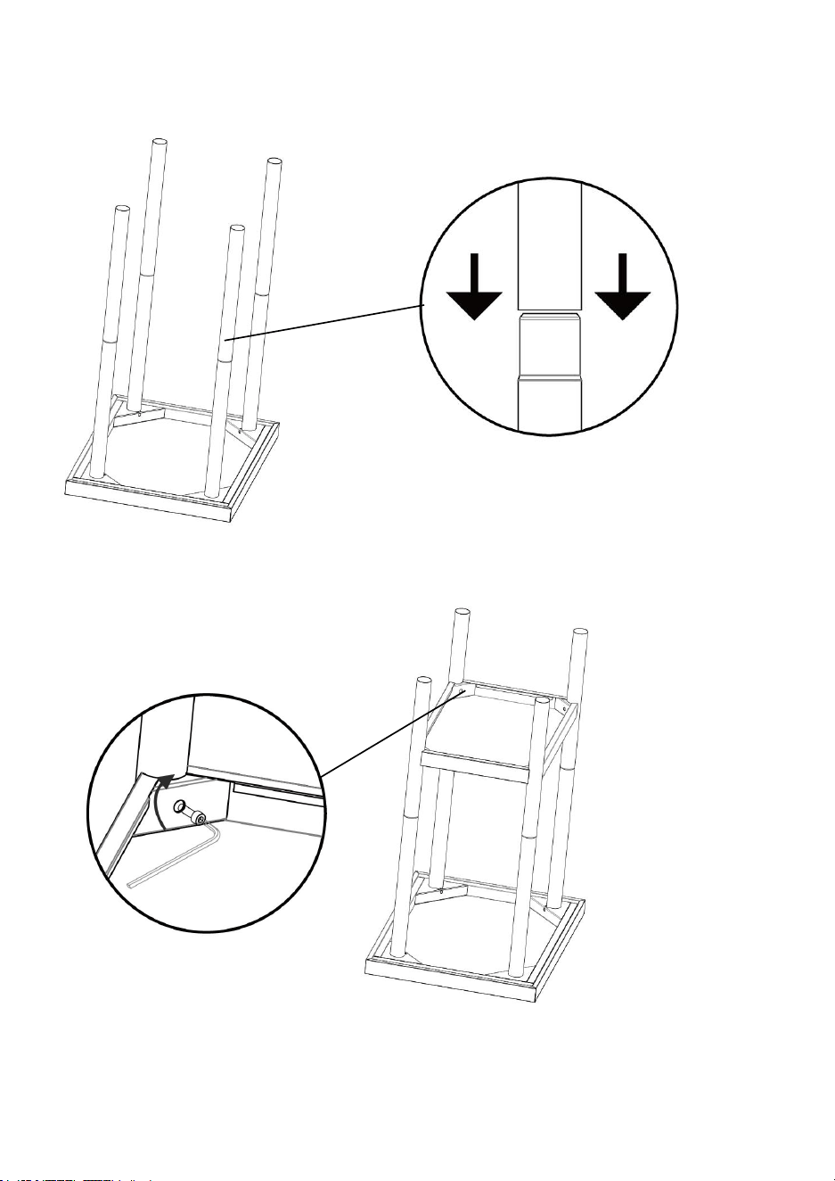
- 8 -
2. Alcuni modelli distinguono il modello dei tubi di supporto superiore e inferiore e
i tubi di supporto superiore e inferiore devono essere coperti
Nota: Questo passaggio può essere omesso per i prodotti con cosce intere ;
3.Installare la partizione in base all'altezza della posizione del foro necessaria, fissare
il foro di montaggio con viti a brugola M6 e la coppia è maggiore o uguale a 25 Nm.
4. Installare l'involucro nel tubo tondo.

- 9 -
5 . Installare i piedini o le ruote di supporto
6. Dopo aver completato l'installazione, capovolgere il banco da lavoro e regolare

- 10 -
l'altezza dei quattro piedini di supporto (o ruote ) per garantire che i quattro piedi
siano vicini al suolo e che il banco da lavoro sia stabile
Nota: se non è necessario spostare il banco di lavoro. Si prega di tenere i freni
sulle ruote per garantire che il tavolo non si muova .
Il banco da lavoro ha un limite di peso massimo, fare attenzione a non superare il
peso massimo
Nota : i passaggi di installazione riportati di seguito sono

- 11 -
solo per HET-24*24-3L
1. Installare il flapper-1 sul banco di lavoro nell'orientamento corretto (fare
riferimento alla direzione del logo), quindi serrarlo con viti M5*12 e cuscinetti piatti
M5 e fissare il deflettore-1 sul banco di lavoro.
Logo
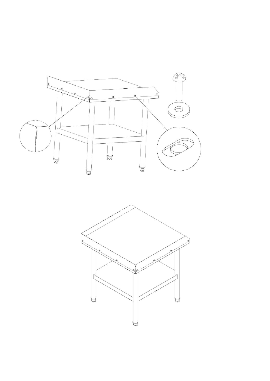
- 12 -
2 .
Il deflettore-2 e il deflettore-1 sono fissati e posizionati correttamente
sul banco da lavoro, quindi fissati con viti M5*12 e cuscinetti piatti M5, e la
piastra del deflettore 1 è fissata sul banco da lavoro. (I passaggi di
installazione di Bezel-3 sono simili, fare riferimento a questo passaggio)
3. Disegno del prodotto finito HET-24*24-3L
- 15 -
Produttore: Shanghaimuxinmuyeyouxiangongsi
Indirizzo: Shuangchenglu 803nong11hao1602A-1609shi, baoshanqu,
shanghai 200000 CN.
Importato in AUS: SIHAO PTY LTD. 1 ROKEVA STREETEASTWOOD
NSW 2122 Australia
Importato negli Stati Uniti: Sanven Technology Ltd. Suite 250, 9166
Anaheim Place, Rancho Cucamonga, CA 91730
REP
EC
E-CrossStu GmbH
Mainzer Landstr.69, 60329 Frankfurt am Main.
REP
UK
YH CONSULTING LIMITED.
C/O YH Consulting Limited Office 147, Centurion
House, London Road, Staines-upon-Thames, Surrey,
TW18 4AX