
USER GUIDE & SERVICE MANUAL
®
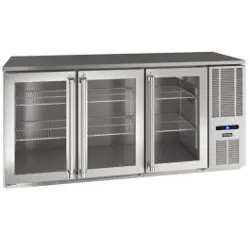
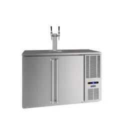
Model: VCBR532-SG01A
USER GUIDE & SERVICE MANUAL
Table of Contents
Click on any section below to jump directly there
Intro
Safety
Safety and Warning
Disposal And Recycling
Installation
Environmental Requirements
Electrical
Cutout & Product Dimensions
General Installation
Grille Installation
Door Swing
Door Adjust
Interior Adjustments
Maintenance
Cleaning
Cleaning Condenser
Extended Non-Use
Operating Instructions
First Use
Control Operation
Airflow and Product Loading
Service
Wine Rack Installation
Troubleshooting
Wire Diagram
Product Liability
Parts
R600a Specifications
System Diagnosis Guide
Compressor Specifications
Troubleshooting Extended
Control Operation - Service
Thermistor
Defrost
Remove Fan and Cover
Warranty
USER GUIDE
Introduction
WELCOME TO VIKING COMMERCIAL
Congratulations on your purchase!
Viking is synonymous with decades of innovation and craftsmanship. Our industry-leading appliances set the standards.
Delivering professional performance and stunning design. Our products have become the standard for elite chefs around the
world.
PRODUCT INFORMATION
Looking for additional information on your product? User Guides, Spec Sheets, and Product Warranty information are available
online at vikingrange.com/commercial.
PROPERTY DAMAGE / INDUSTRY CONCERNS
In the unlikely event property damage or personal injury is suspected related to a Viking Commercial product, please take the
following steps:
1. Customer Care must be contacted at +1.616.754.5601
2. Service or repairs performed on the unit without prior written approval is not permitted. If the units have been
alteredorrepairedintheeldwithoutpriorwrittenapproval,claimswillnotbeeligible.
GENERAL INQUIRIES
1260 E. Van Deinse • Greenville, MI 48838 •
+1.616.754.5601
Website: vikingrange.com/commercial
commercial@vikingrange.com
CONNECT WITH US
SERVICE & PARTS ASSISTANCE
Monday – Friday 8:00 am to 4:30 pm CST
+1.616.754.5601
Service Email: commercialservice@vikingrange.com
3
USER GUIDE
Safety and Warning
Safety and Warning
NOTICE
Please read all instructions before installing,
operating, or servicing the appliance.
Use this appliance for its intended purpose only and follow
these general precautions with those listed throughout this
guide:
SAFETY ALERT DEFINITIONS
Throughout this guide are safety items labeled with a
Danger, Warning, or Caution based on the risk type:
Danger means that failure to follow this safety
statement will result in severe personal injury or
death.
Warning means that failure to follow this safety
statement could result in serious personal injury
or death.
Caution means that failure to follow this safety
statement may result in minor or moderate
personal injury, property, or equipment damage.
Caution: risk of re, ammable refrigerant and
blowing gas used.
GENERAL PRECAUTIONS
Use this appliance for its intended purpose only and follow
these general precautions with those listed throughout this
guide.
This appliance is not intended for use by persons
(including children) with reduced physical, sensory or
mental capabilities, or lack of experience or knowledge,
unless they have been given supervision or instruction
concerning use of the appliance by a person responsible for
their safety.
Children should be supervised to ensure that they do not
play with this appliance.
Keep clear of obstruction all ventilation openings
in the appliance enclosure or in the structure for
building-in.
Please accord to local regulations regarding
disposal of the appliance for its ammable
refrigerant and blowing gas. Before you scrap the
appliance, please remove the doors to prevent
child entrapment.
Do not store explosive substances such as
aerosol cans with a ammable propellant in this
appliance.
Do not use mechanical devices or other means
to accelerate the defrosting process, other than
those recommended by the manufacturer.
Do not damage the refrigerating circuit.
Do not use electrical appliances inside the food/
ice storage compartments unless they are of the
type recommended by the manufacturer.
DANGER
!
WARNING
!
WARNING
!
WARNING
!
WARNING
!
WARNING
!
CAUTION
!
4
USER GUIDE
Safety and Warning
DO NOT use medical devices or other means to
accelerate the defrosting process other than
those recommended by the manufacturer. DO
NOT use an ice pick or other sharp instrument to
help speed up defrosting. These instruments can
puncture the inner lining or damage the cooling
unit. DO NOT use any type of heater to defrost.
Using a heater to speed up defrosting can cause
personal injury and damage to the inner lining.
NOTICE
Do not lift unit by door handle.
Never install or operate the unit behind closed
doors. Be sure front grille is free of obstruction.
Obstructing free airow can cause the unit to
malfunction and will void the warranty.
Failure to clean the condenser every six months
can cause the unit to malfunction. This could void
the warranty.
Allow unit temperature to stabilize for 24 hours
before use.
Do not block any internal fans.
Use only genuine factory replacement parts.
Imitation parts can damage the unit, aect its
operation or performance and may void the
warranty.
This appliance is intended to be used in household and
similar applications such as:
• Sta kitchen areas in shops, oces and other working
environments.
• Farm houses and by clients in hotels, motels and other
residential type environments.
• Bed and breakfast type environments.
• Catering and similar non-retail applications.
5
USER GUIDE
Disposal and Recycling
Disposal and Recycling
RISK OF CHILD ENTRAPMENT. Before you throw
away your old refrigerator or freezer, take o
the doors and leave shelves in place so children
may not easily climb inside.
If the unit is being removed from service for disposal,
check and obey all federal, state, and local regulations
regarding the disposal and recycling of refrigeration
appliances, and follow these steps completely:
1. Remove all consumable contents from the unit.
2. Unplug the electrical cord from its socket.
3. Remove the door(s)/drawer(s).
DANGER
!
6
USER GUIDE
Environmental Requirements
Environmental Requirements
This unit is designed to operate between 50°F (10°C) and
100°F (38°C). Higher ambient temperatures may reduce
the unit’s ability to reach low temperatures and/or reduce
ice production on applicable models.
For best performance, keep the unit out of direct sunlight
and away from heat generating equipment.
In climates where high humidity and dew points are
present, condensation may appear on outside surfaces.
This is considered normal. The condensation will
evaporate when the humidity drops.
CAUTION
!
Damages caused by ambient temperatures of
40°F (4°C) or below are not covered by the
warranty.
7
USER GUIDE
Electrical
Electrical
WARNING
!
SHOCK HAZARD — Electrical Grounding
Required. Never attempt to repair or perform
maintenance on the unit until the electricity has
been disconnected.
Never remove the round grounding prong from
the plug and never use a two-prong grounding
adapter.
Altering, cutting or removing power cord,
removing power plug, or direct wiring can cause
serious injury, fire, loss of property and/or life,
and will void the warranty.
Never use an extension cord to connect power to
the unit.
Always keep your working area dry.
NOTICE
Electrical installation must observe all state and
local codes. This unit requires connection to a
grounded (three-prong), polarized receptacle
that has been placed by a qualified electrician.
The unit requires a grounded and polarized 115 VAC,
60 Hz, 15A power supply (normal household current). An
individual, properly grounded branch circuit or circuit
breaker is recommended. A GFCI (ground fault circuit
interrupter) is usually not required for fixed location
appliances and is not recommended for your unit because
it could be prone to nuisance tripping. However, be sure
to consult your local codes.
See CUTOUT & PRODUCT DIMENSIONS for recommended
receptacle location.
8
USER GUIDE
Cutout & Product Dimensions
Cutout & Product Dimensions
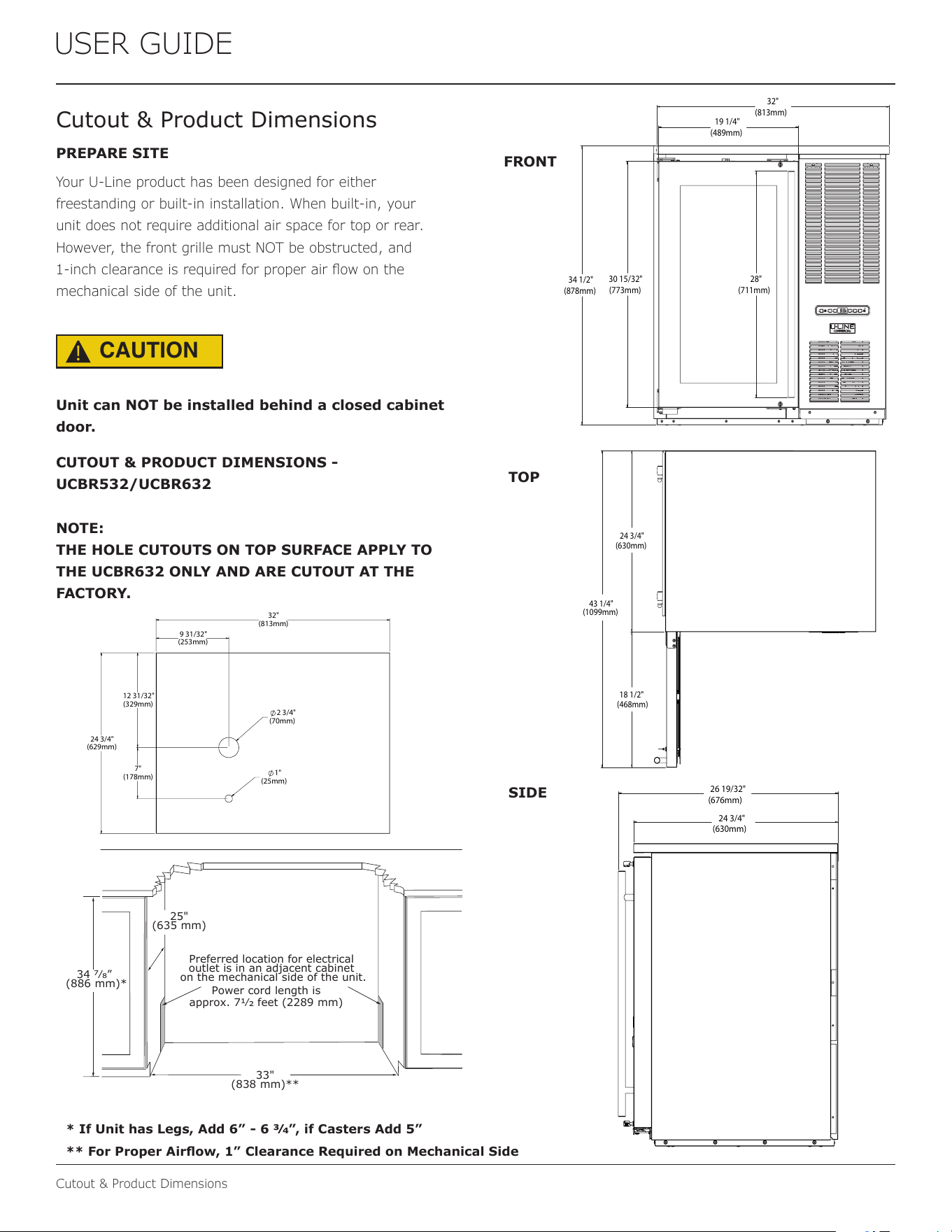
PREPARE SITE
Your U-Line product has been designed for either
freestanding or built-in installation. When built-in, your
unit does not require additional air space for top or rear.
However, the front grille must NOT be obstructed, and
1-inch clearance is required for proper air ow on the
mechanical side of the unit.
CAUTION
!
Unit can NOT be installed behind a closed cabinet
door.
CUTOUT & PRODUCT DIMENSIONS -
UCBR532/UCBR632
NOTE:
THE HOLE CUTOUTS ON TOP SURFACE APPLY TO
THE UCBR632 ONLY AND ARE CUTOUT AT THE
FACTORY.
FRONT
TOP
SIDE
34 1/2"
(878mm)
30 15/32"
(773mm)
32"
(813mm)
19 1/4"
(489mm)
28"
(711mm)
43 1/4"
(1099mm)
24 3/4"
(630mm)
18 1/2"
(468mm)
24 3/4"
(630mm)
26 19/32"
(676mm)
33"
(838 mm)**
Preferred location for electrical
outlet is in an adjacent cabinet
on the mechanical side of the unit.
34 7⁄8”
(886 mm)*
25"
(635 mm)
Power cord length is
approx. 71⁄2 feet (2289 mm)
* If Unit has Legs, Add 6” - 6 3⁄4”, if Casters Add 5”
** For Proper Airow, 1” Clearance Required on Mechanical Side
9 31/32"
(253mm)
12 31/32"
(329mm)
7"
(178mm)
32"
(813mm)
24 3/4"
(629mm)
2 3/4"
(70mm)
1"
(25mm)
9
USER GUIDE
Cutout & Product Dimensions
Cutout & Product Dimensions
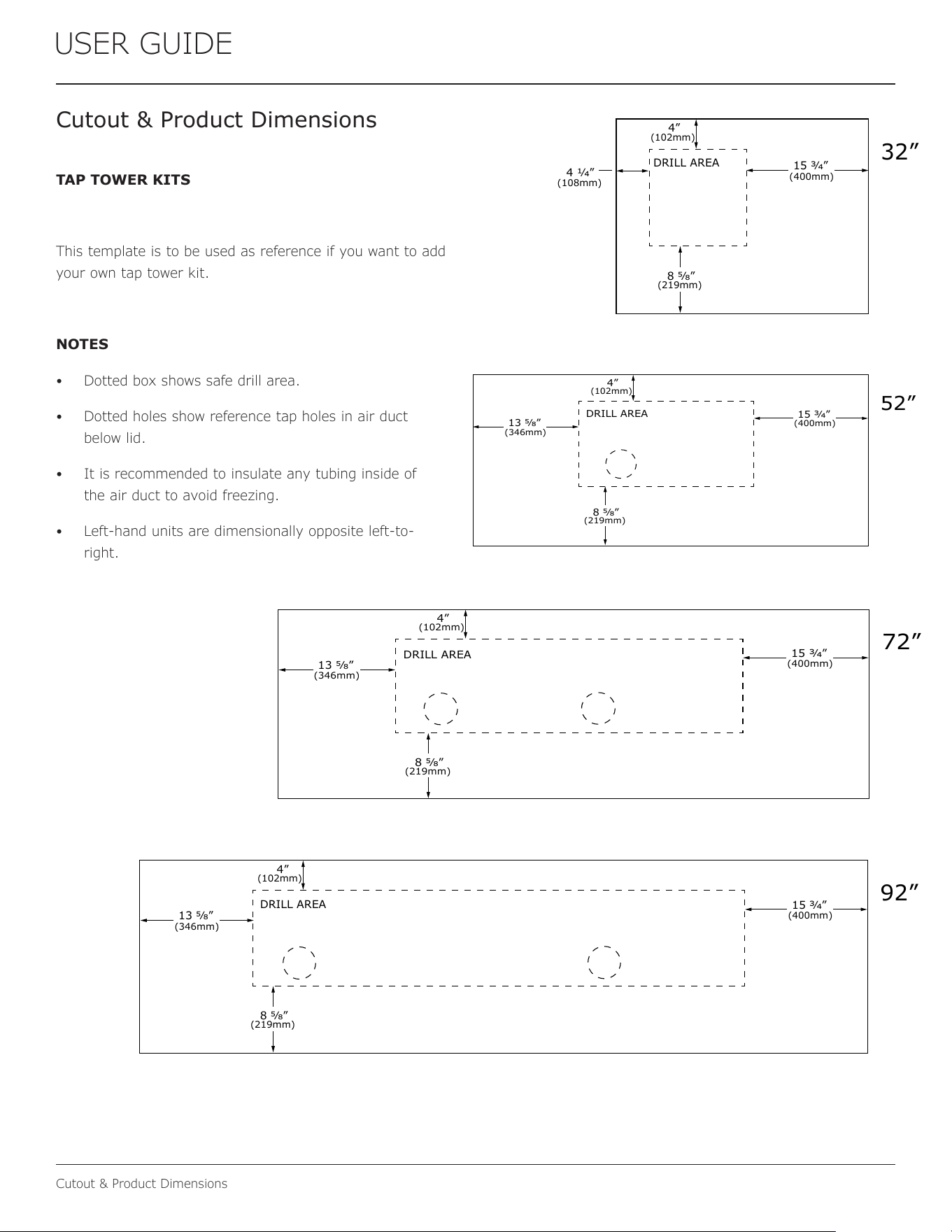
TAP TOWER KITS
This template is to be used as reference if you want to add
your own tap tower kit.
NOTES
• Dotted box shows safe drill area.
• Dotted holes show reference tap holes in air duct
below lid.
• It is recommended to insulate any tubing inside of
the air duct to avoid freezing.
• Left-hand units are dimensionally opposite left-to-
right.
DRILL AREA
4”
(102mm)
15 3⁄4”
8 5⁄8”
(400mm)
13 5⁄8”
(346mm)
(219mm)
52”
DRILL AREA
4”
(102mm)
15 3⁄4”
8 5⁄8”
(400mm)
13 5⁄8”
(346mm)
(219mm)
72”
DRILL AREA
4”
(102mm)
15 3⁄4”
8 5⁄8”
(400mm)
13 5⁄8”
(346mm)
(219mm)
92”
DRILL AREA
4 1⁄4”
4”
(108mm)
(102mm)
8 5⁄8”
(219mm)
32”
15 3⁄4”
(400mm)
10
USER GUIDE
General Installation
General Installation
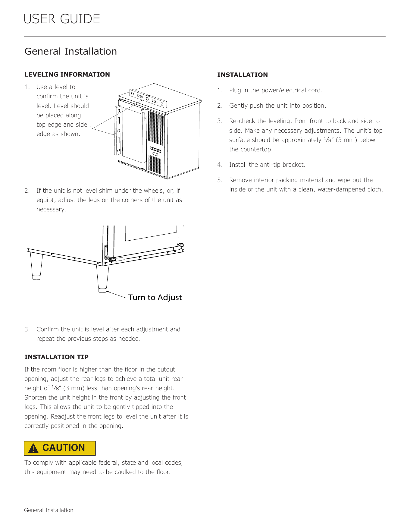
LEVELING INFORMATION
1. Use a level to
conrm the unit is
level. Level should
be placed along
top edge and side
edge as shown.
2. If the unit is not level shim under the wheels, or, if
equipt, adjust the legs on the corners of the unit as
necessary.
3. Conrm the unit is level after each adjustment and
repeat the previous steps as needed.
INSTALLATION TIP
If the room oor is higher than the oor in the cutout
opening, adjust the rear legs to achieve a total unit rear
height of 1⁄8” (3 mm) less than opening’s rear height.
Shorten the unit height in the front by adjusting the front
legs. This allows the unit to be gently tipped into the
opening. Readjust the front legs to level the unit after it is
correctly positioned in the opening.
To comply with applicable federal, state and local codes,
this equipment may need to be caulked to the oor.
INSTALLATION
1. Plug in the power/electrical cord.
2. Gently push the unit into position.
3. Re-check the leveling, from front to back and side to
side. Make any necessary adjustments. The unit’s top
surface should be approximately 1⁄8” (3 mm) below
the countertop.
4. Install the anti-tip bracket.
5. Remove interior packing material and wipe out the
inside of the unit with a clean, water-dampened cloth.
1
Turn to Adjust
CAUTION
!
11
USER GUIDE
Grille Installation
Grille Installation
REMOVING AND INSTALLING GRILLE
Disconnect electric power to the unit before
removing the grille.
When using the unit, the grille must be installed.
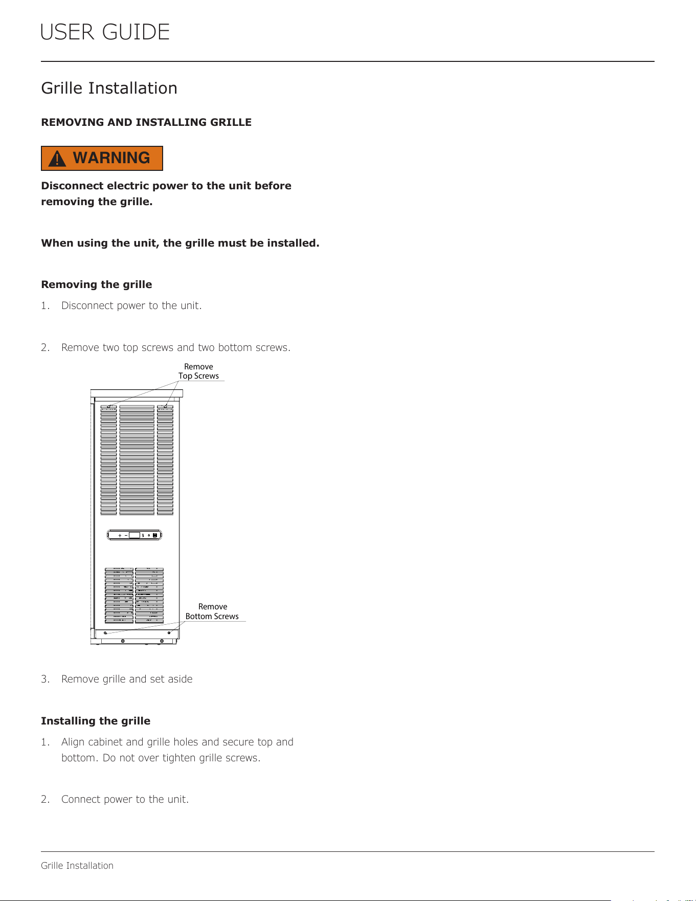
Removing the grille
1. Disconnect power to the unit.
2. Remove two top screws and two bottom screws.
3. Remove grille and set aside
Installing the grille
1. Align cabinet and grille holes and secure top and
bottom. Do not over tighten grille screws.
2. Connect power to the unit.
WARNING
!
Remove
Top Screws
Remove
Bottom Screws
12
USER GUIDE
Door Swing
Door Swing
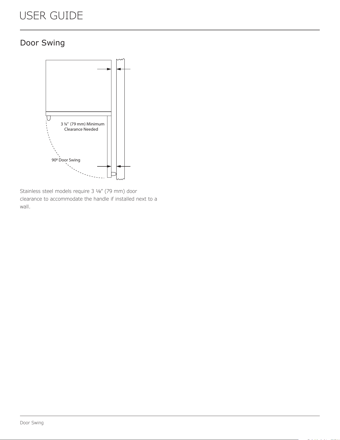
Stainless steel models require 3 1⁄8” (79 mm) door
clearance to accommodate the handle if installed next to a
wall.
3 1⁄8” (79 mm) Minimum
Clearance Needed
900 Door Swing
13
USER GUIDE
Door Adjustments
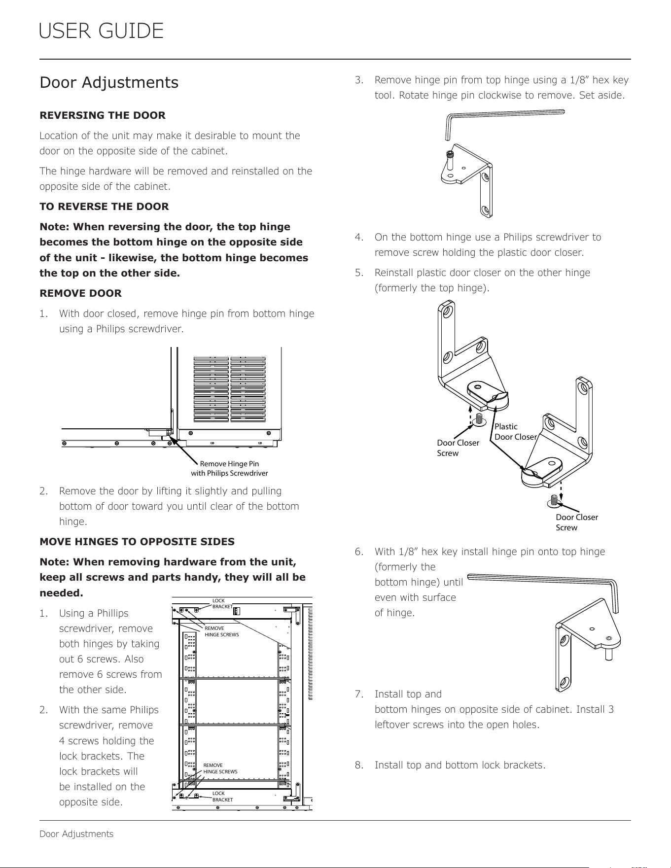
3. Remove hinge pin from top hinge using a 1/8” hex key
tool. Rotate hinge pin clockwise to remove. Set aside.
4. On the bottom hinge use a Philips screwdriver to
remove screw holding the plastic door closer.
5. Reinstall plastic door closer on the other hinge
(formerly the top hinge).
6. With 1/8” hex key install hinge pin onto top hinge
(formerly the
bottom hinge) until
even with surface
of hinge.
7. Install top and
bottom hinges on opposite side of cabinet. Install 3
leftover screws into the open holes.
8. Install top and bottom lock brackets.
Door Adjustments
REVERSING THE DOOR
Location of the unit may make it desirable to mount the
door on the opposite side of the cabinet.
The hinge hardware will be removed and reinstalled on the
opposite side of the cabinet.
TO REVERSE THE DOOR
Note: When reversing the door, the top hinge
becomes the bottom hinge on the opposite side
of the unit - likewise, the bottom hinge becomes
the top on the other side.
REMOVE DOOR
1. With door closed, remove hinge pin from bottom hinge
using a Philips screwdriver.
2. Remove the door by lifting it slightly and pulling
bottom of door toward you until clear of the bottom
hinge.
MOVE HINGES TO OPPOSITE SIDES
Note: When removing hardware from the unit,
keep all screws and parts handy, they will all be
needed.
1. Using a Phillips
screwdriver, remove
both hinges by taking
out 6 screws. Also
remove 6 screws from
the other side.
2. With the same Philips
screwdriver, remove
4 screws holding the
lock brackets. The
lock brackets will
be installed on the
opposite side.
Remove Hinge Pin
with Philips Screwdriver
Plastic
Door Closer
Door Closer
Screw
Door Closer
Screw
LOCK
BRACKET
REMOVE
HINGE SCREWS
REMOVE
HINGE SCREWS
LOCK
BRACKET
14
USER GUIDE
Door Adjustments
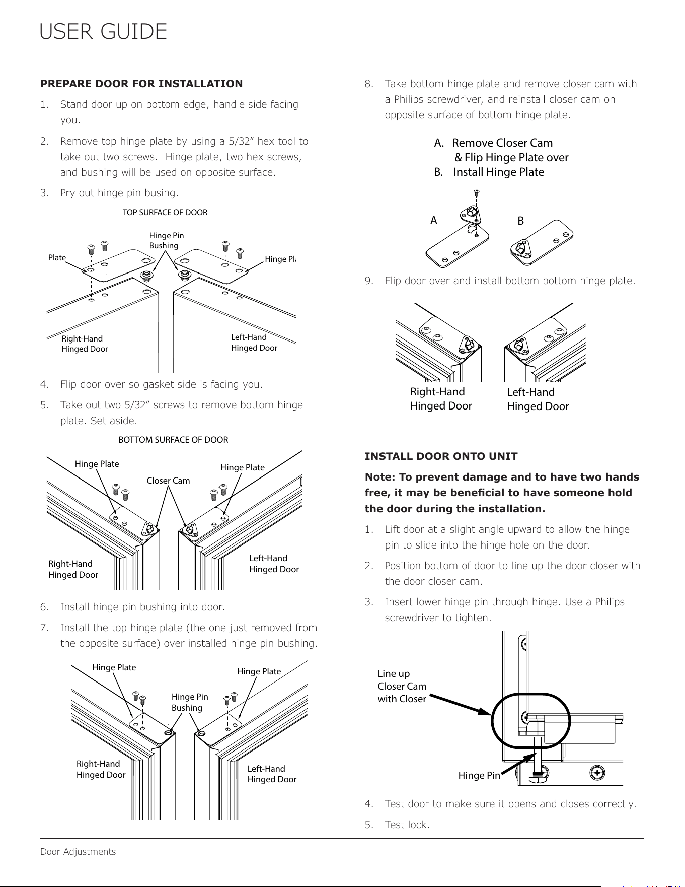
PREPARE DOOR FOR INSTALLATION
1. Stand door up on bottom edge, handle side facing
you.
2. Remove top hinge plate by using a 5/32” hex tool to
take out two screws. Hinge plate, two hex screws,
and bushing will be used on opposite surface.
3. Pry out hinge pin busing.
4. Flip door over so gasket side is facing you.
5. Take out two 5/32” screws to remove bottom hinge
plate. Set aside.
6. Install hinge pin bushing into door.
7. Install the top hinge plate (the one just removed from
the opposite surface) over installed hinge pin bushing.
8. Take bottom hinge plate and remove closer cam with
a Philips screwdriver, and reinstall closer cam on
opposite surface of bottom hinge plate.
9. Flip door over and install bottom bottom hinge plate.
INSTALL DOOR ONTO UNIT
Note: To prevent damage and to have two hands
free, it may be benecial to have someone hold
the door during the installation.
1. Lift door at a slight angle upward to allow the hinge
pin to slide into the hinge hole on the door.
2. Position bottom of door to line up the door closer with
the door closer cam.
3. Insert lower hinge pin through hinge. Use a Philips
screwdriver to tighten.
4. Test door to make sure it opens and closes correctly.
5. Test lock.
Left-Hand
Hinged Door
Right-Hand
Hinged Door
BOTTOM SURFACE OF DOOR
Closer Cam
Hinge Plate
Hinge Plate
Left-Hand
Hinged Door
Hinge Pin
Bushing
Hinge Plate
Hinge Plate
Right-Hand
Hinged Door
TOP SURFACE OF DOOR
Line up
Closer Cam
with Closer
Hinge Pin
BOTTOM SURFACE OF DOOR
Hinge Pin
Bushing
Left-Hand
Hinged Door
Right-Hand
Hinged Door
Hinge Plate
Hinge Plate
A. Remove Closer Cam
& Flip Hinge Plate over
B. Install Hinge Plate
A
B
Left-Hand
Hinged Door
Right-Hand
Hinged Door
15
USER GUIDE
First Use
NOTICE
Temperature displayed reects actual
temperature inside unit.
If the temperature displayed is dierent than selected, the
unit is progressing towards the selected temperature. Time
to reach set point varies based upon ambient temperature,
temperature of product loaded, door openings, etc. U-Line
recommends allowing the unit to reach set points before
loading.
First Use
Initial startup requires no adjustments. If the unit was
turned o, press to turn unit on. See “Control
Operation” section for more details.
16
USER GUIDE
Control Operation
Control Operation
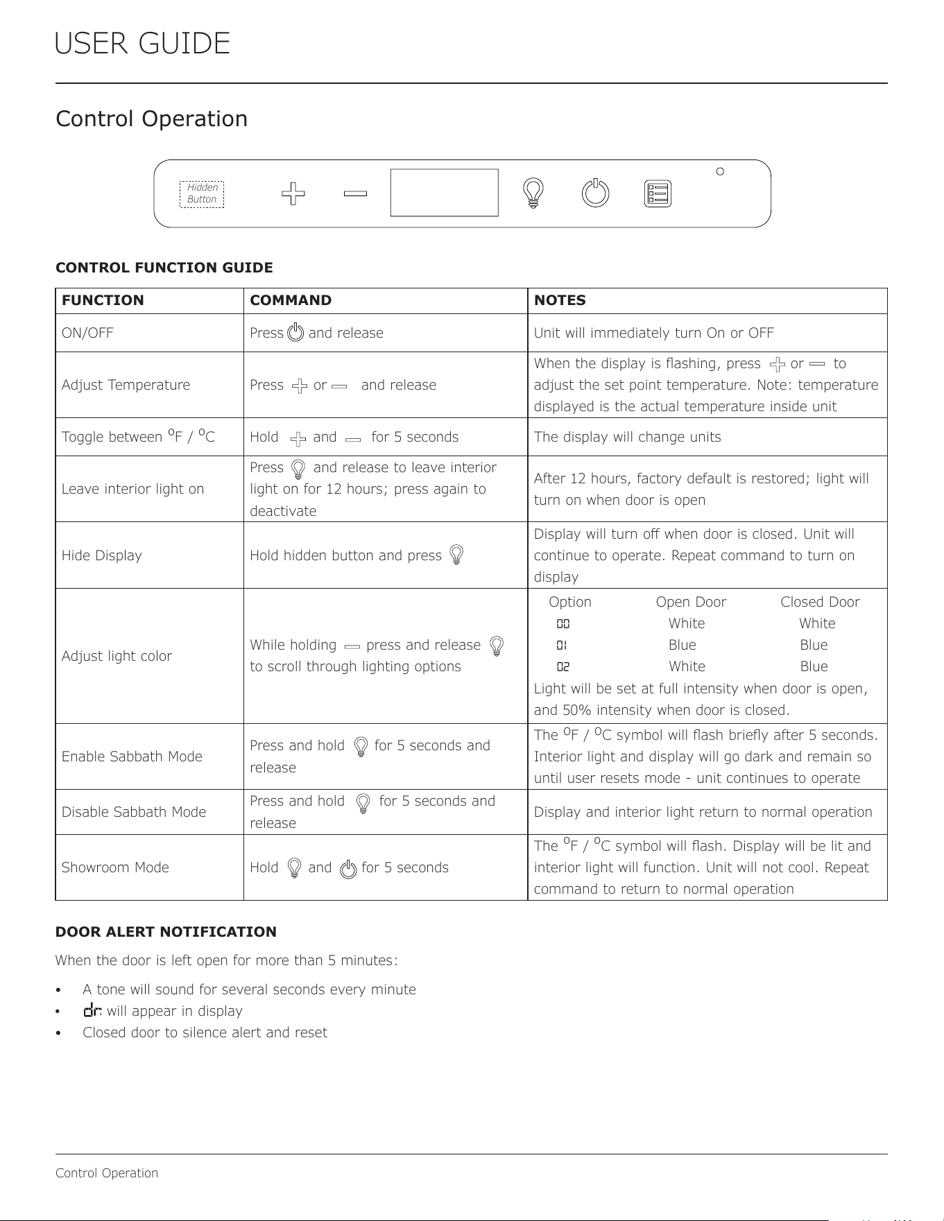
CONTROL FUNCTION GUIDE
FUNCTION COMMAND NOTES
ON/OFF Press and release Unit will immediately turn On or OFF
Adjust Temperature Press or and release
When the display is ashing, press or to
adjust the set point temperature. Note: temperature
displayed is the actual temperature inside unit
Toggle between
º
F /
º
C Hold and for 5 seconds The display will change units
Leave interior light on
Press and release to leave interior
light on for 12 hours; press again to
deactivate
After 12 hours, factory default is restored; light will
turn on when door is open
Hide Display Hold hidden button and press
Display will turn o when door is closed. Unit will
continue to operate. Repeat command to turn on
display
Adjust light color
While holding press and release
to scroll through lighting options
Option Open Door Closed Door
00 White White
01 Blue Blue
02 White Blue
Light will be set at full intensity when door is open,
and 50% intensity when door is closed.
Enable Sabbath Mode
Press and hold for 5 seconds and
release
The
o
F /
o
C symbol will ash briey after 5 seconds.
Interior light and display will go dark and remain so
until user resets mode - unit continues to operate
Disable Sabbath Mode
Press and hold for 5 seconds and
release
Display and interior light return to normal operation
Showroom Mode Hold and for 5 seconds
The
º
F /
º
C symbol will ash. Display will be lit and
interior light will function. Unit will not cool. Repeat
command to return to normal operation
DOOR ALERT NOTIFICATION
When the door is left open for more than 5 minutes:
• A tone will sound for several seconds every minute
• will appear in display
• Closed door to silence alert and reset
Hidden
Button
17
USER GUIDE
Airow & Product Loading
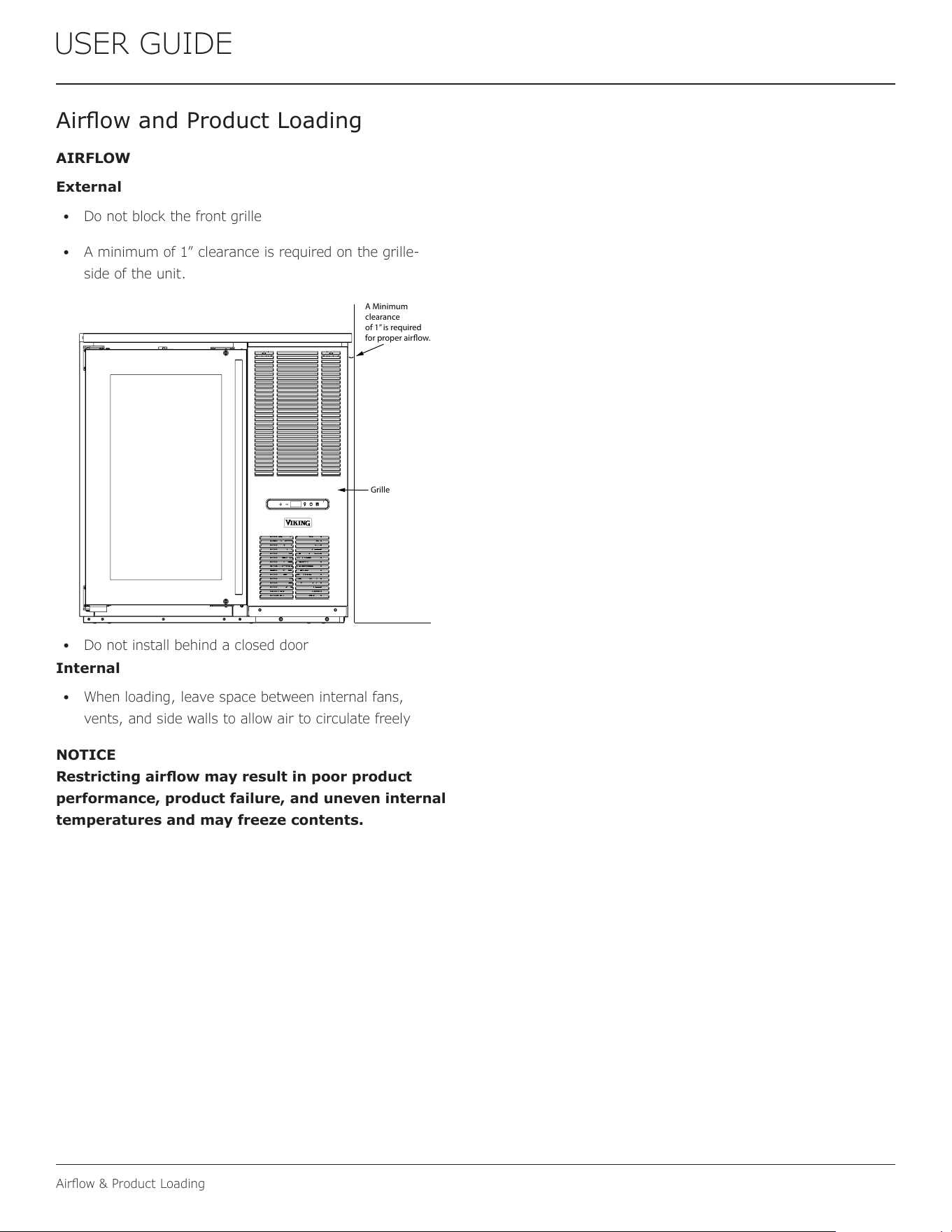
Airow and Product Loading
AIRFLOW
External
• Do not block the front grille
• A minimum of 1” clearance is required on the grille-
side of the unit.
• Do not install behind a closed door
Internal
• When loading, leave space between internal fans,
vents, and side walls to allow air to circulate freely
NOTICE
Restricting airow may result in poor product
performance, product failure, and uneven internal
temperatures and may freeze contents.
A Minimum
clearance
of 1” is required
for proper airow.
Grille
®
18
USER GUIDE
Interior Adjustments
Interior Adjustments
REMOVING AND INSTALLING SHELVES
Adjusting Interior Shelves
Models equipped with wire rack or glass cantilever shelves
have an adjustable mounting system. To adjust or simply
remove shelves for cleaning, follow the instructions below.
1. Remove all product from shelf.
2. Coming from underneath the shelf, lift both the front
and rear of the shelf.
3. Carefully slide shelf out of unit being careful not to
scratch the interior liner.
4. Installation is the reverse of removal.Adjusting
Shelf Height
Shelf height may be adjusted to accommodate a broad
range of product. To alter your shelf spacing follow the
instructions below.
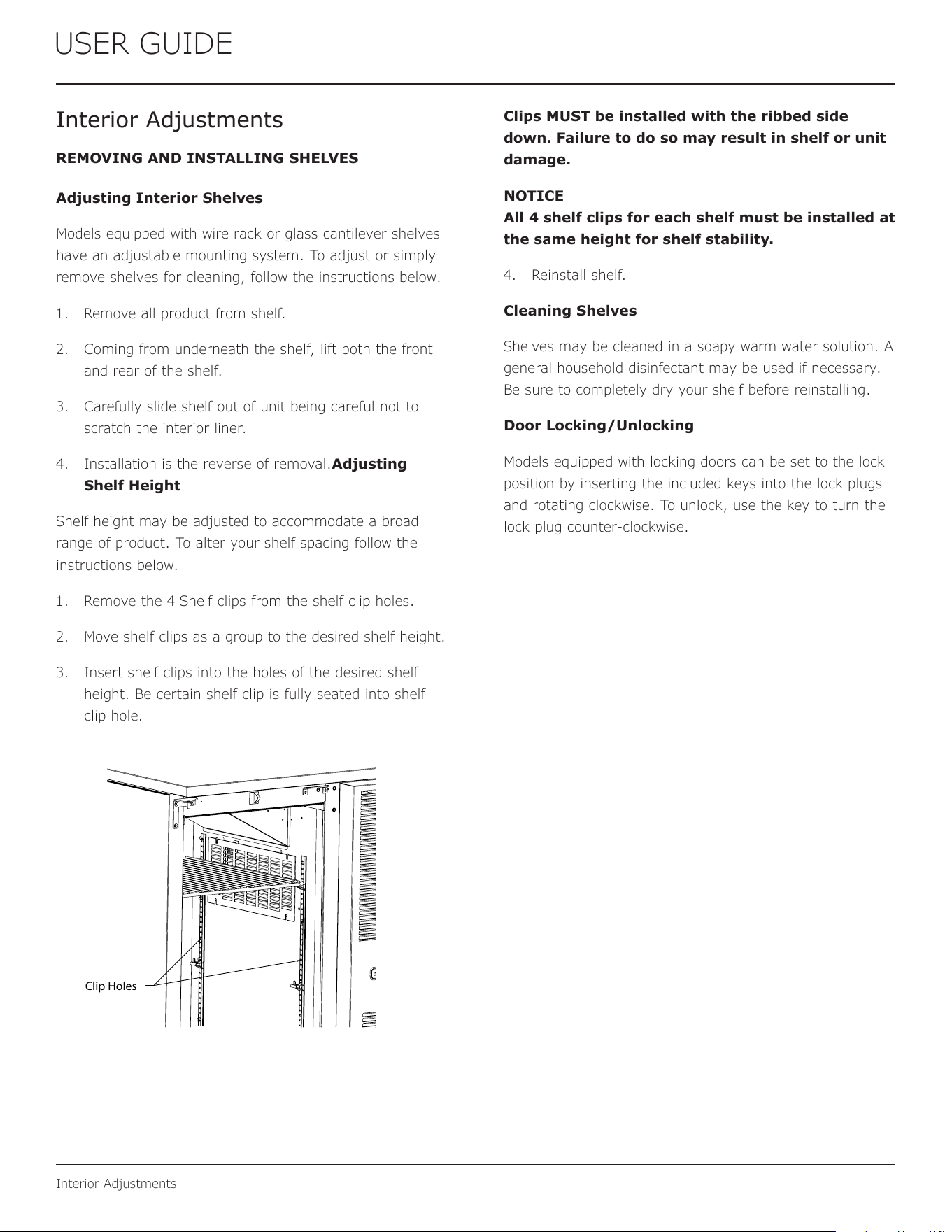
1. Remove the 4 Shelf clips from the shelf clip holes.
2. Move shelf clips as a group to the desired shelf height.
3. Insert shelf clips into the holes of the desired shelf
height. Be certain shelf clip is fully seated into shelf
clip hole.
Clips MUST be installed with the ribbed side
down. Failure to do so may result in shelf or unit
damage.
NOTICE
All 4 shelf clips for each shelf must be installed at
the same height for shelf stability.
4. Reinstall shelf.
Cleaning Shelves
Shelves may be cleaned in a soapy warm water solution. A
general household disinfectant may be used if necessary.
Be sure to completely dry your shelf before reinstalling.
Door Locking/Unlocking
Models equipped with locking doors can be set to the lock
position by inserting the included keys into the lock plugs
and rotating clockwise. To unlock, use the key to turn the
lock plug counter-clockwise.
Clip Holes
19
USER GUIDE
Cleaning
Cleaning
CLEANING VS. SANITIZING
This guide will address both the cleaning and the sanitizing
of the unit.
Clean the unit to remove dried food and spills, to prevent
build-up of grime, and to maintain the natural luster
stainless steel surfaces.
Sanitize the unit when exposed to raw meat juice or
human germs such as from a sneeze or being touched by
someone who is ill. Sanitizing the unit can also be part of
regular cleaning routine.
Stainless Surfaces
Stainless door panels, handles and frames can discolor
when exposed to chlorine gas, pool chemicals, saltwater or
cleaners with bleach.
Keep your stainless unit looking new by cleaning with a
good quality all-in-one stainless steel cleaner and polish
monthly. For best results use Claire
®
Stainless Steel
Polish and Cleaner. Comparable products are acceptable.
Frequent cleaning will remove surface contamination that
could lead to rust. Some installations may require cleaning
weekly.
Do not clean with steel wool pads.
Do not use stainless steel cleaners or polishes on
any glass surfaces.
Clean any glass surfaces with a non-chlorine glass cleaner.
Do not use cleaners not specically intended for
stainless steel on stainless steel surfaces (this
includes glass, tile, and counter cleaners).
If any surface discoloring or rusting appears, clean it
quickly with Bon-Ami
®
or Barkeepers Friend Cleanser
®
and
a nonabrasive cloth. Always clean with the grain. Always
nish with Claire
®
Stainless Steel Polish and Cleaner or
comparable product to prevent further problems.
Using abrasive pads such as ScotchBrite™ will
cause the graining in the stainless steel to
become blurred.
Rust not cleaned up promptly can penetrate the
surface of the stainless steel and complete
removal of the rust may not be possible.
CLEAN INTERIOR COMPONENTS
Use warm or hot water with dish soap to clean all removed
components and interior surfaces. You may use a vinegar and
water solution in place of soap. Proceed to sanitizing.
Note: Cleaning soaps and vinegar solutions are not
sanitizers.
SANITIZE INTERIOR COMPONENTS AND SURFACES
Choose a Commercial Sanitizer Safe for Stainless
Steel
• Read the directions for proper use to ensure that the
surface will actually be sanitized
• Many products require rinsing with water after use,
especially when food will be touching the surface
• Some products require a wait time before rinsing
• Verify the sanitizer you are using is safe for stainless
steel.
Mix Your Own Sanitizer
Isopropyl Alcohol (rubbing alcohol)
1. Fill a clean, empty spray bottle with isopropyl alcohol
2. Spray surface
3. Wait 20 minutes
4. Dampen a non-abrasive cloth with isopropyl alcohol and
wipe down surface
5. Dry surface with a clean dry non-abrasive cloth
Unscented Bleach and Water
1. Create a solution of 1 tablespoon of unscented bleach
with one gallon of water.
2. Submerse small parts for no more than 3 minutes - rinse
immediately and allow to air dry or dry with a disposable
paper towel.
3. Fill a clean, empty spray bottle with bleach solution.
4. Spray surface.
5. After 2-3 minutes, use clean potable water to thoroughly
rinse o surface. Allow to air dry or dry with a disposable
paper towel.
6. Sanitize the door and all holes where the hinges attach to
the unit and the brackets attach to the door as well as all
the screws.
CLEAN EXTERIOR SURFACES
Use Bon-Ami
®
or Barkeepers Friend Cleanser
®
and a
nonabrasive cloth. Always clean with the grain. Always nish
with Claire
®
Stainless Steel Polish and Cleaner or comparable
product to prevent further problems.
20
USER GUIDE
Cleaning
INTERIOR CLEANING & SANITIZING
NOTICE
Do not use any solvent-based or abrasive
cleaners. These types of cleaners may transfer taste
and/or odor to the interior products and damage or
discolor the interior.
DEFROSTING
Under normal conditions this unit does not require manual
defrosting. Minor frost on the rear wall or visible through
the evaporator plate vents is normal and will melt during
each cycle.
If there is excessive build-up of 1/4” (6 mm) or more,
manually defrost the unit.
Ensure the door is closing and sealing properly.
High ambient temperature and excessive humidity can also
produce frost.
CAUTION
!
DO NOT use an ice pick or other sharp instrument
to help speed up defrosting. These instruments
can puncture the inner lining or damage the
cooling unit. DO NOT use any type of heater to
defrost. Using a heater to speed up defrosting can
cause personal injury and damage to the inner
lining.
NOTICE
The drain pan was not designed to capture the
water created when manually defrosting. To
prevent water from overowing the drain pan
and possibly damaging water sensitive ooring,
the unit must be removed from cabinetry.
To defrost:
1. Disconnect power to the unit.
2. Remove all products from the interior
3. Prop the door in an open position (2 in. [50 mm]
minimum).
4. Allow the frost to melt naturally.
5. After the frost melts completely, clean the interior and
all removed components. (See INTERIOR CLEANING).
6. When the interior is dry, reconnect power and turn
unit on.
21
USER GUIDE
Cleaning Condenser
Cleaning Condenser
INTERVAL - EVERY SIX MONTHS
To maintain operational eciency, keep the front grille free
of dust and lint, and clean the condenser when necessary.
Depending on environmental conditions, more or less
frequent cleaning may be necessary.
WARNING
!
Disconnect electric power to the unit before
cleaning the condenser.
NOTICE
DO NOT use any type of cleaner on the condenser
unit. Condenser may be cleaned using a vacuum,
soft brush, or compressed air.
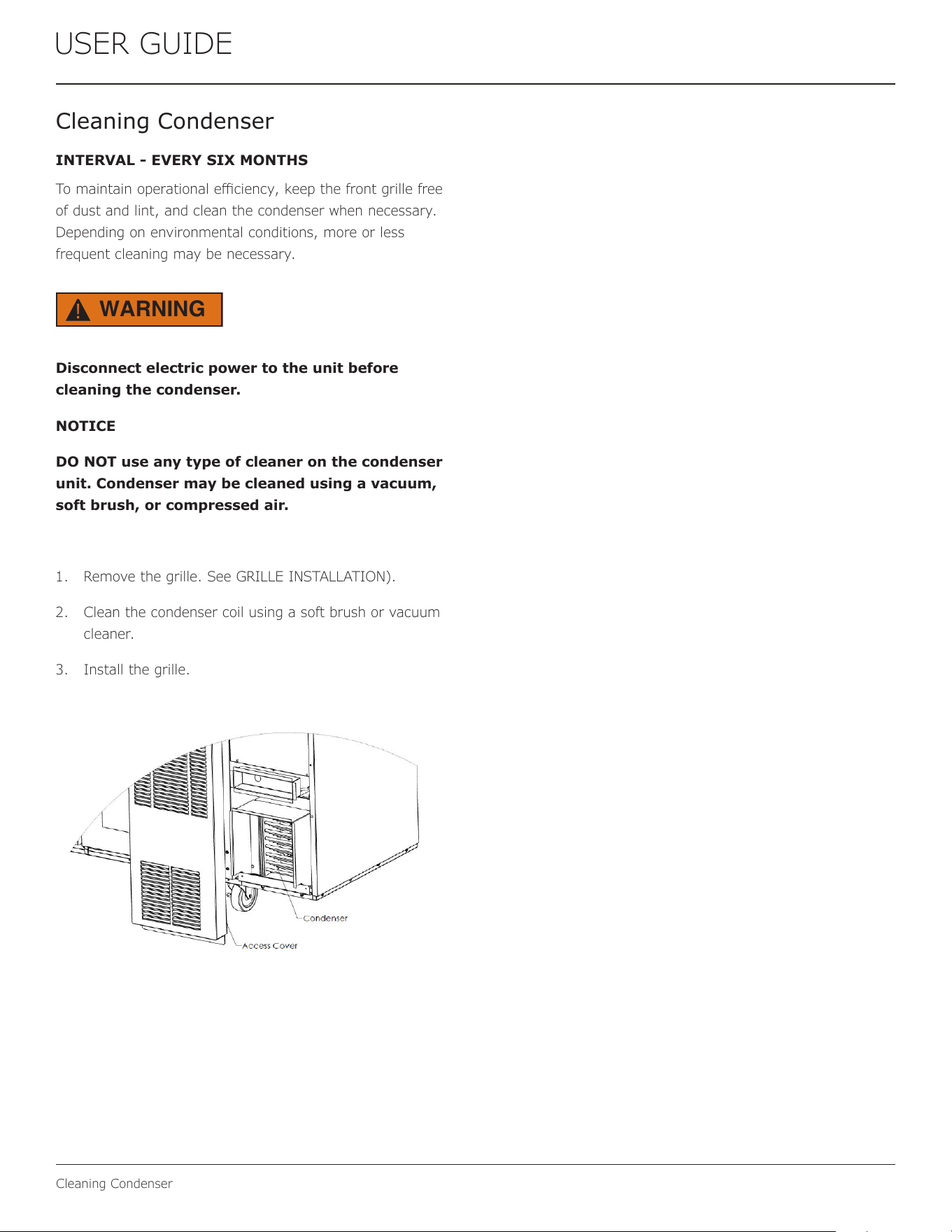
1. Remove the grille. See GRILLE INSTALLATION).
2. Clean the condenser coil using a soft brush or vacuum
cleaner.
3. Install the grille.
22
USER GUIDE
Wine Rack Installation
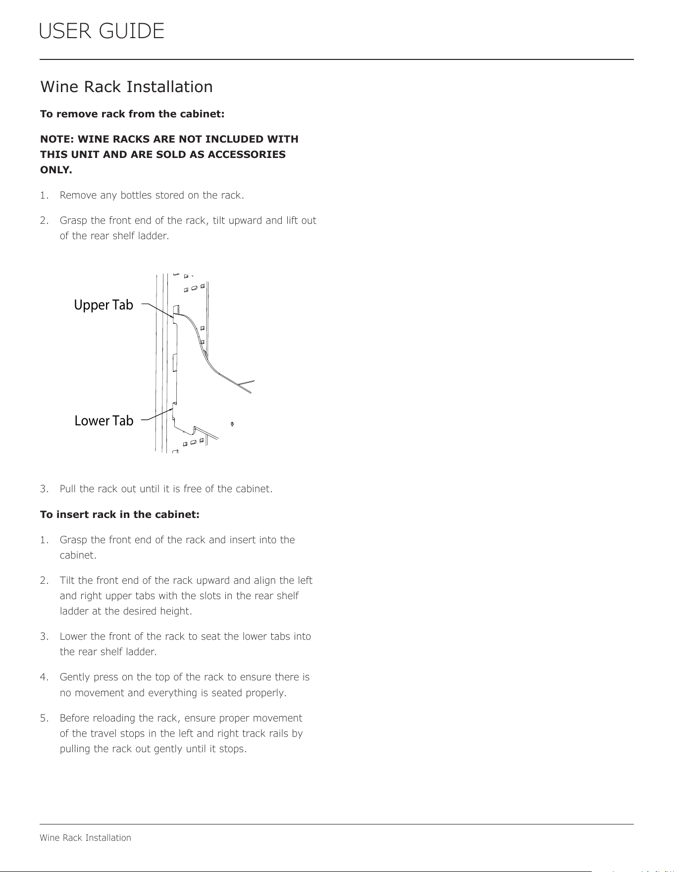
Wine Rack Installation
To remove rack from the cabinet:
NOTE: WINE RACKS ARE NOT INCLUDED WITH
THIS UNIT AND ARE SOLD AS ACCESSORIES
ONLY.
1. Remove any bottles stored on the rack.
2. Grasp the front end of the rack, tilt upward and lift out
of the rear shelf ladder.
3. Pull the rack out until it is free of the cabinet.
To insert rack in the cabinet:
1. Grasp the front end of the rack and insert into the
cabinet.
2. Tilt the front end of the rack upward and align the left
and right upper tabs with the slots in the rear shelf
ladder at the desired height.
3. Lower the front of the rack to seat the lower tabs into
the rear shelf ladder.
4. Gently press on the top of the rack to ensure there is
no movement and everything is seated properly.
5. Before reloading the rack, ensure proper movement
of the travel stops in the left and right track rails by
pulling the rack out gently until it stops.
Upper Tab
Lower Tab
23
USER GUIDE
Extended Non-Use
Extended Non-Use
VACATION/HOLIDAY, PROLONGED SHUTDOWN
The following steps are recommended for periods of
extended non-use:
1. Remove all consumable content from the unit.
2. Disconnect the power cord from its outlet/socket
and leave it disconnected until the unit is returned to
service.
3. If any ice is visible inside the unit, allow ice to thaw
naturally.
4. Clean and dry the interior of the unit. Ensure all water
has been removed from the unit.
5. Clean the system. (See CLEANING)
6. The door must remain open to prevent formation of
mold and mildew. Open door a minimum of 2” (50
mm) to provide the necessary ventilation.
WINTERIZATION
If the unit will be exposed to temperatures of 40
o
F (5
o
C) or
less, the steps above must be followed.
For questions regarding winterization, please call
U-Line at 414.354.0300.
CAUTION
!
Damage caused by freezing temperatures is not
covered by the warranty.
24
USER GUIDE
Troubleshooting
If you think your U-Line product is malfunctioning, read the
CONTROL OPERATION section to clearly understand the
function of the control.
If the problem persists, read the NORMAL OPERATING
SOUNDS and TROUBLESHOOTING GUIDE sections below
to help you quickly identify common problems and possible
causes and remedies. Most often, this will resolve the
problem without the need to call for service.
If you do not understand a troubleshooting remedy, or your
product needs service, contact U-Line Corporation directly
at +1.414.354.0300.
When you call, you will need your product Model and Serial
Numbers. This information appears on the Model and Serial
number plate located on the upper right or rear wall of the
interior of your product.
All models incorporate rigid foam insulated cabinets to
provide high thermal eciency and maximum sound
reduction for its internal working components. Despite this
technology, your model may make sounds that are
unfamiliar.
Normal operating sounds may be more noticeable because
of the unit’s environment. Hard surfaces such as cabinets,
wood, vinyl or tiled oors and paneled walls have a
tendency to reect normal appliance operating noises.
Listed below are common refrigeration components with a
brief description of the normal operating sounds they
make. NOTE: Your product may not contain all the
components listed.
• Compressor: The compressor makes a hum or pulsing
sound that may be heard when it operates.
BEFORE CALLING FOR SERVICE
TROUBLESHOOTING GUIDE
ELECTROCUTION HAZARD. Never attempt to
repair or perform maintenance on the unit
before disconnecting the main electrical power.
Troubleshooting - What to check when problems occur:
NORMAL OPERATING SOUNDS
IF SERVICE IS REQUIRED
Troubleshooting
• Evaporator: Refrigerant owing through an evaporator
may sound like boiling liquid.
• Condenser Fan: Air moving through a condenser may
be heard.
• Automatic Defrost Drain Pan: Water may be heard
dripping or running into the drain pan when the unit is
in the defrost cycle.
DANGER
!
Problem Possible Cause and Remedy
Interior Light
Does Not
Illuminate
If the unit is cooling, it may be in
Sabbath mode.
Light Remains
on When Door
Is Closed.
Turn o light switch if equipped.
Adjust light actuator bracket on bottom
of door.
Unit Develops
Frost on
Internal
Surfaces.
Ensure the door is closing and sealing
properly.
Unit Develops
Condensation
on External
Surfaces.
The unit is exposed to excessive
humidity. Moisture will dissipate as
humidity levels decrease.
Product is Not
Cold Enough
Air temperature does not indicate
product temperature. See CHECKING
PRODUCT TEMPERATURE below.
Adjust the temperature to a cooler set
point.
Ensure unit is not located in excessive
ambient temperatures or in direct
sunlight.
Ensure the door is closing and sealing
properly.
Ensure the interior light has not
remained on too long.
Ensure nothing is blocking the front
grille, found at the bottom of the unit.
Ensure the condenser coil is clean and
free of any dirt or lint build-up.
25
USER GUIDE
Troubleshooting
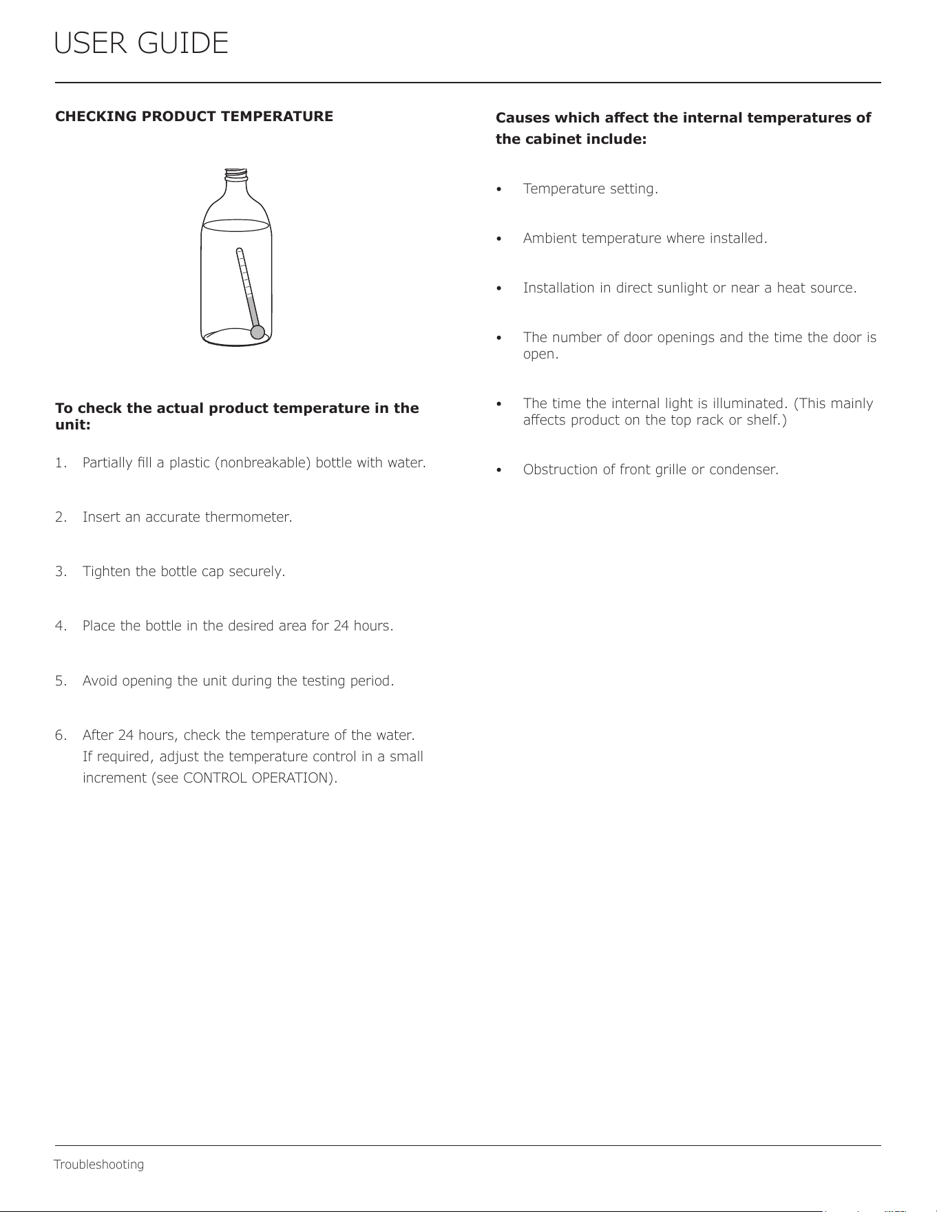
CHECKING PRODUCT TEMPERATURE
To check the actual product temperature in the
unit:
1. Partially ll a plastic (nonbreakable) bottle with water.
2. Insert an accurate thermometer.
3. Tighten the bottle cap securely.
4. Place the bottle in the desired area for 24 hours.
5. Avoid opening the unit during the testing period.
6. After 24 hours, check the temperature of the water.
If required, adjust the temperature control in a small
increment (see CONTROL OPERATION).
Causes which aect the internal temperatures of
the cabinet include:
• Temperature setting.
• Ambient temperature where installed.
• Installation in direct sunlight or near a heat source.
• The number of door openings and the time the door is
open.
• The time the internal light is illuminated. (This mainly
aects product on the top rack or shelf.)
• Obstruction of front grille or condenser.
26
USER GUIDE
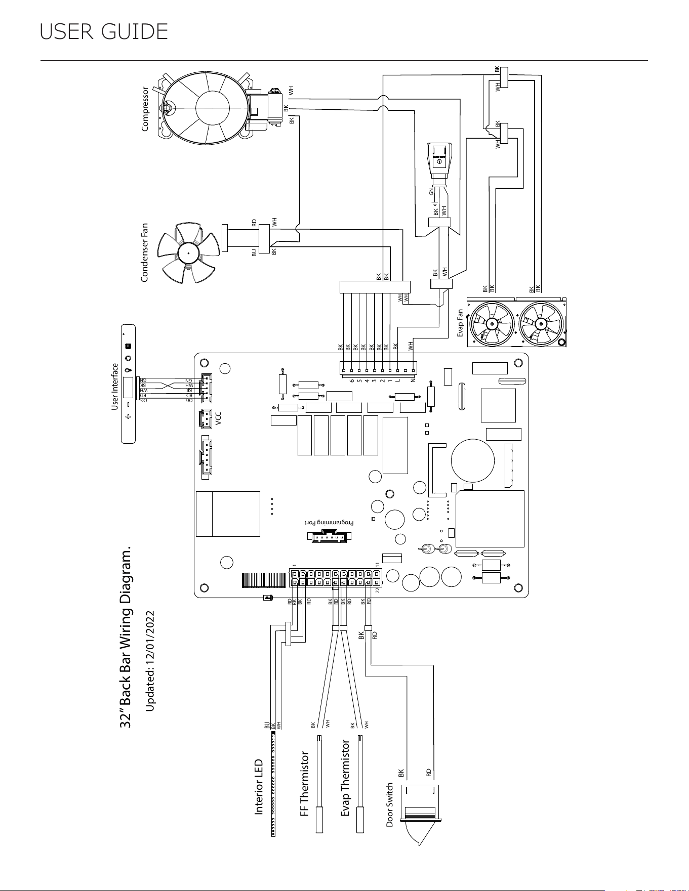
FF Thermistor
Evap Thermistor
Door Switch
Evap Fan
User Interface
Interior LED
OG
RD
BK
WH
GN
Compressor
Condenser Fan
WH
BK
GN
BK
WH
WH
WH
BK
BK
BK
BK
BK
BK
BK
BK
BK
WH WH
WH
BK
BK
BK
BK
BK
BK
BK
BK
BK
RD
RD
BK
WH
RD
RD
BK
BK
BK
BK
WH
WH
BK
RD
BK
1
1122
N
L
1
2
3
4
5
6
Programming Port
VCC
32” Back Bar Wiring Diagram.
Updated: 12/01/2022
RD
OG
RD
BK
WH
GN
RD
BK
BU
WH
RDBU
BK
BK
BK
WH
27
USER GUIDE
Product Liability
Product Liability
Field service technicians are authorized to make an initial
assessment in the event of reported damages. If there are
any questions about the process involved, the technician
should call the manufacturer for further explanation.
While inspecting for defects or installation issues, photos
should be taken to document any damages or issues found.
During the assessment, if the service technician is able to
nd the source of the damage and it can be resolved by
replacement of a part, the servicer is authorized to replace
the part in question. The part that caused the damage
must be returned to the manufacturer in its entirety. The
part must be clearly labeled with the serial number of the
unit it was removed from, the date, and the servicer who
removed the part.
If the service technician determines the damage is the
result of installation issues (water connection/drain, etc.),
the consumer would be notied and the issues shall be
resolved at the direction of the consumer.
If damage is evident and the service technician is unable
to nd the source, the manufacturer must be contacted at
+1.616.754.5601 for further direction.
1260 Van Deinse St. Greenville, MI
T: +1.616.754.5601
Website: vikingrange.com/commercial
28
USER GUIDE
Parts
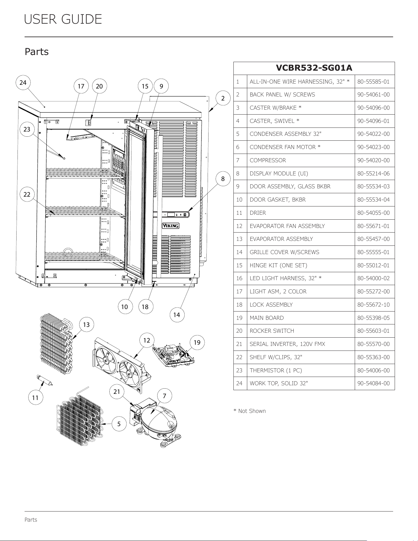
Pa rts
VCBR532-SG01A
1 ALL-IN-ONE WIRE HARNESSING, 32" * 80-55585-01
2 BACK PANEL W/ SCREWS 90-54061-00
3 CASTER W/BRAKE * 90-54096-00
4 CASTER, SWIVEL * 90-54096-01
5 CONDENSER ASSEMBLY 32" 90-54022-00
6 CONDENSER FAN MOTOR * 90-54023-00
7 COMPRESSOR 90-54020-00
8 DISPLAY MODULE (UI) 80-55214-06
9 DOOR ASSEMBLY, GLASS BKBR 80-55534-03
10 DOOR GASKET, BKBR 80-55534-04
11 DRIER 80-54055-00
12 EVAPORATOR FAN ASSEMBLY 80-55671-01
13 EVAPORATOR ASSEMBLY 80-55457-00
14 GRILLE COVER W/SCREWS 80-55555-01
15 HINGE KIT (ONE SET) 80-55012-01
16 LED LIGHT HARNESS, 32" * 80-54000-02
17 LIGHT ASM, 2 COLOR 80-55272-00
18 LOCK ASSEMBLY 80-55672-10
19 MAIN BOARD 80-55398-05
20 ROCKER SWITCH 80-55603-01
21 SERIAL INVERTER, 120V FMX 80-55570-00
22 SHELF W/CLIPS, 32" 80-55363-00
23 THERMISTOR (1 PC) 80-54006-00
24 WORK TOP, SOLID 32" 90-54084-00
* Not Shown
2
8
20 1517
22
10
9
18
14
24
23
13
11
19
12
7
21
5
®
29
USER GUIDE
R-600A Specications
USER GUIDE
R-600A Specifications 1
u-line.com
SAFETY • INSTALLATION & INTEGRATION • OPERATING INSTRUCTIONS • MAINTENANCE • SERVICE
R-600A Specifications
For R-600a refrigerant service tips and more videos, go
to: www.u-line.com/videos.
WARNING
!
Flammability warnings for a pure-iso-butane
refrigerant.
Technician m ust observe al l federal, st ate and local la ws regarding r efrigerants .
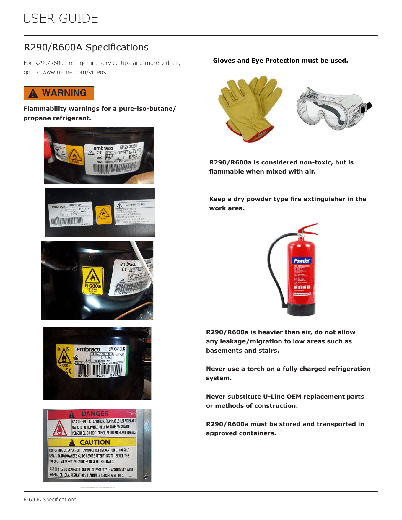
Gloves and Eye Protection must be used.
R-600a is considered non-toxic, but is flammable
when mixed with air.
Keep a dry powder type fire extinguisher in the
work area.
R-600a is heavier than air, do not allow any
leakage/migration to low areas such as
basements and stairs.
Never use a torch on a fully charged
refrigeration system.
Never substitute U-Line OEM replacement parts
or methods of construction.
R-600a must be stored and transported in
approved containers.
R290/R600A Specications
For R290/R600a refrigerant service tips and more videos,
go to: www.u-line.com/videos.
Flammability warnings for a pure-iso-butane/
propane refrigerant.
USER GUIDE
R-600A Specifications 1
u-line.com
SAFETY • INSTALLATION & INTEGRATION • OPERATING INSTRUCTIONS • MAINTENANCE • SERVICE
R-600A Specifications
For R-600a refrigerant service tips and more videos, go
to: www.u-line.com/videos
.
WARNING
!
Flammability warnings for a pure-iso-butane
refrigerant.
Technician m ust observe all fed eral, state and local laws regardi ng refrigerant s.
Gloves and Eye Protection must be used.
R-600a is considered non-toxic, but is flammable
when mixed with air.
Keep a dry powder type fire extinguisher in the
work area.
R-600a is heavier than air, do not allow any
leakage/migration to low areas such as
basements and stairs.
Never use a torch on a fully charged
refrigeration system.
Never substitute U-Line OEM replacement parts
or methods of construction.
R-600a must be stored and transported in
approved containers.
WARNING
!
R290/R600a is considered non-toxic, but is
ammable when mixed with air.
Keep a dry powder type re extinguisher in the
work area.
R290/R600a is heavier than air, do not allow
any leakage/migration to low areas such as
basements and stairs.
Never use a torch on a fully charged refrigeration
system.
Never substitute U-Line OEM replacement parts
or methods of construction.
R290/R600a must be stored and transported in
approved containers.
30
R-600A Specications
USER GUIDE
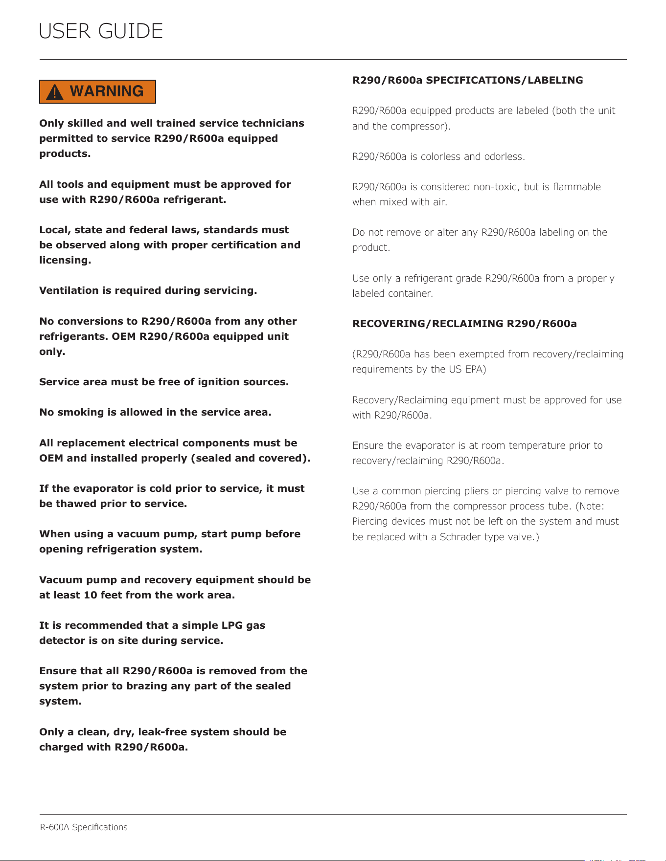
Only skilled and well trained service technicians
permitted to service R290/R600a equipped
products.
All tools and equipment must be approved for
use with R290/R600a refrigerant.
Local, state and federal laws, standards must
be observed along with proper certication and
licensing.
Ventilation is required during servicing.
No conversions to R290/R600a from any other
refrigerants. OEM R290/R600a equipped unit
only.
Service area must be free of ignition sources.
No smoking is allowed in the service area.
All replacement electrical components must be
OEM and installed properly (sealed and covered).
If the evaporator is cold prior to service, it must
be thawed prior to service.
When using a vacuum pump, start pump before
opening refrigeration system.
Vacuum pump and recovery equipment should be
at least 10 feet from the work area.
It is recommended that a simple LPG gas
detector is on site during service.
Ensure that all R290/R600a is removed from the
system prior to brazing any part of the sealed
system.
Only a clean, dry, leak-free system should be
charged with R290/R600a.
R290/R600a SPECIFICATIONS/LABELING
R290/R600a equipped products are labeled (both the unit
and the compressor).
R290/R600a is colorless and odorless.
R290/R600a is considered non-toxic, but is ammable
when mixed with air.
Do not remove or alter any R290/R600a labeling on the
product.
Use only a refrigerant grade R290/R600a from a properly
labeled container.
RECOVERING/RECLAIMING R290/R600a
(R290/R600a has been exempted from recovery/reclaiming
requirements by the US EPA)
Recovery/Reclaiming equipment must be approved for use
with R290/R600a.
Ensure the evaporator is at room temperature prior to
recovery/reclaiming R290/R600a.
Use a common piercing pliers or piercing valve to remove
R290/R600a from the compressor process tube. (Note:
Piercing devices must not be left on the system and must
be replaced with a Schrader type valve.)
WARNING
!
31
USER GUIDE
R-600A Specications
USER GUIDE
R-600A Specifications 3
u-line.com
SAFETY • INSTALLATION & INTEGRATION • OPERATING INSTRUCTIONS • MAINTENANCE • SERVICE
Evacuate/reclaim via the piecing pliers to ensure the
system is empty of R-600a before any system work is
performed.
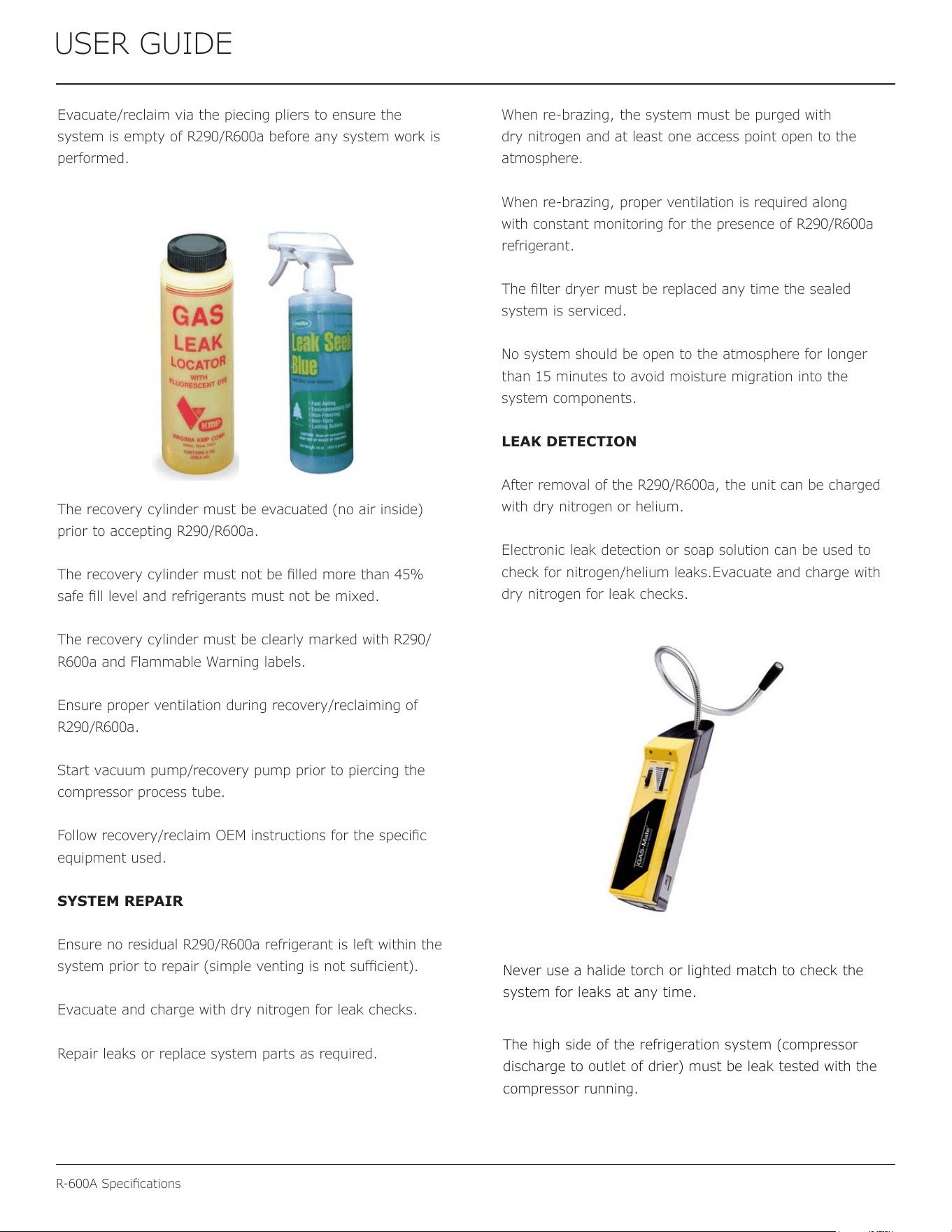
The recovery cylinder must be evacuated (no air inside)
prior to accepting R-600a.
The recovery cylinder must not be filled more than 45%
safe fill level and refrigerants must not be mixed.
The recovery cylinder must be clearly marked with R-
600a and Flammable Warning labels.
Ensure proper ventilation during recovery/reclaiming of R-
600a.
Start vacuum pump/recovery pump prior to piercing the
compressor process tube.
Follow recovery/reclaim OEM instructions for the specific
equipment used.
SYSTEM REPAIR
Ensure no residual R-600a refrigerant is left within the
system prior to repair (simple venting is not sufficient).
Evacuate and charge with dry nitrogen for leak checks.
Repair leaks or replace system parts as required.
When re-brazing, the system must be purged with dry
nitrogen and at least one access point open to the
atmosphere.
When re-brazing, proper ventilation is required along with
constant monitoring for the presence of R600a refrigerant.
The filter dryer must be replaced any time the sealed
system is serviced.
No system should be open to the atmosphere for longer
than 15 minutes to avoid moisture migration into the
system components.
LEAK DETECTION
After removal of the R-600a, the unit can be charged with
dry nitrogen or helium.
Electronic leak detection or soap solution can be used to
check for nitrogen/helium leaks.
Never use a halide torch or lighted match to check the
system for leaks at any time.
The high side of the refrigeration system (compressor
discharge to outlet of drier) must be leak tested with the
compressor running.
Evacuate/reclaim via the piecing pliers to ensure the
system is empty of R290/R600a before any system work is
performed.
The recovery cylinder must be evacuated (no air inside)
prior to accepting R290/R600a.
The recovery cylinder must not be lled more than 45%
safe ll level and refrigerants must not be mixed.
The recovery cylinder must be clearly marked with R290/
R600a and Flammable Warning labels.
Ensure proper ventilation during recovery/reclaiming of
R290/R600a.
Start vacuum pump/recovery pump prior to piercing the
compressor process tube.
Follow recovery/reclaim OEM instructions for the specic
equipment used.
SYSTEM REPAIR
Ensure no residual R290/R600a refrigerant is left within the
system prior to repair (simple venting is not sucient).
Evacuate and charge with dry nitrogen for leak checks.
Repair leaks or replace system parts as required.
When re-brazing, the system must be purged with
dry nitrogen and at least one access point open to the
atmosphere.
When re-brazing, proper ventilation is required along
with constant monitoring for the presence of R290/R600a
refrigerant.
The lter dryer must be replaced any time the sealed
system is serviced.
No system should be open to the atmosphere for longer
than 15 minutes to avoid moisture migration into the
system components.
LEAK DETECTION
After removal of the R290/R600a, the unit can be charged
with dry nitrogen or helium.
Electronic leak detection or soap solution can be used to
check for nitrogen/helium leaks.Evacuate and charge with
dry nitrogen for leak checks.
32
R-600A Specications
USER GUIDE
USER GUIDE
R-600A Specifications 4
u-line.com
SAFETY • INSTALLATION & INTEGRATION • OPERATING INSTRUCTIONS • MAINTENANCE • SERVICE
The low side of the refrigeration system (evaporator,
compressor and suction line) must be leak tested with the
compressor off (equalized pressure).
RECHARGING
No air is ever to be allowed inside the refrigeration system
(R-600a refrigerant or dry nitrogen only).
Never use a torch on a fully charged refrigeration system.
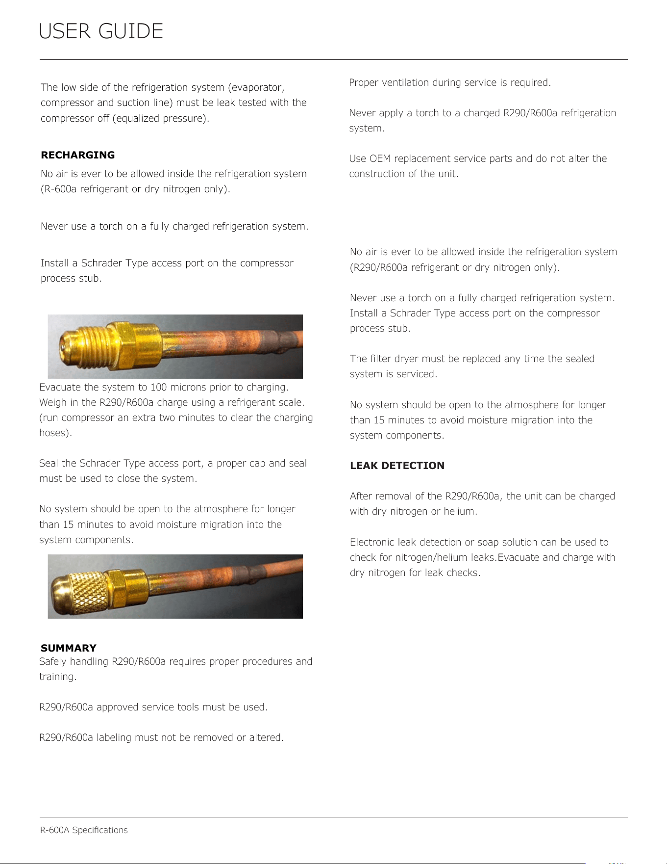
Install a Schrader Type access port on the compressor
process stub.
Evacuate the system to 100 microns prior to charging.
Weigh in the R-600a charge using a refrigerant scale. (run
compressor an extra two minutes to clear the charging
hoses).
Seal the Schrader Type access port, a proper cap and seal
must be used to close the system.
SUMMARY
Safely handling R-600a requires proper procedures and
training.
R-600a approved service tools must be used.
R-600a labeling must not be removed or altered.
Proper ventilation during service is required.
Never apply a torch to a charged R-600a refrigeration
system.
Use OEM replacement service parts and do not alter the
construction of the unit.
No air is ever to be allowed inside the refrigeration system
(R290/R600a refrigerant or dry nitrogen only).
Never use a torch on a fully charged refrigeration system.
Install a Schrader Type access port on the compressor
process stub.
The lter dryer must be replaced any time the sealed
system is serviced.
No system should be open to the atmosphere for longer
than 15 minutes to avoid moisture migration into the
system components.
LEAK DETECTION
After removal of the R290/R600a, the unit can be charged
with dry nitrogen or helium.
Electronic leak detection or soap solution can be used to
check for nitrogen/helium leaks.Evacuate and charge with
dry nitrogen for leak checks.
Evacuate the system to 100 microns prior to charging.
Weigh in the R290/R600a charge using a refrigerant scale.
(run compressor an extra two minutes to clear the charging
hoses).
Seal the Schrader Type access port, a proper cap and seal
must be used to close the system.
No system should be open to the atmosphere for longer
than 15 minutes to avoid moisture migration into the
system components.
Safely handling R290/R600a requires proper procedures and
training.
R290/R600a approved service tools must be used.
R290/R600a labeling must not be removed or altered.
Proper ventilation during service is required.
Never apply a torch to a charged R290/R600a refrigeration
system.
Use OEM replacement service parts and do not alter the
construction of the unit.
33
USER GUIDE
System Diagnosis Guide
System Diagnosis Guide
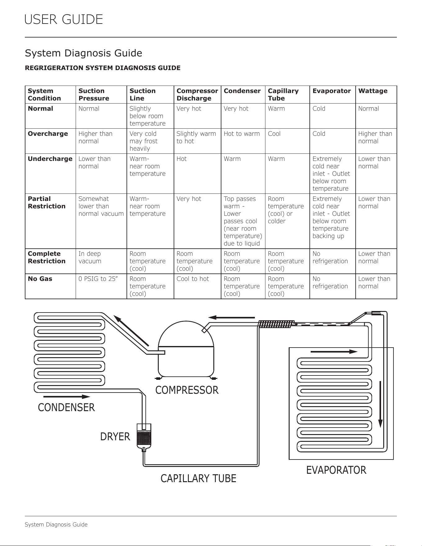
REGRIGERATION SYSTEM DIAGNOSIS GUIDE
System
Condition
Suction
Pressure
Suction
Line
Compressor
Discharge
Condenser Capillary
Tube
Evaporator Wattage
Normal Normal Slightly
below room
temperature
Very hot Very hot Warm Cold Normal
Overcharge Higher than
normal
Very cold
may frost
heavily
Slightly warm
to hot
Hot to warm Cool Cold Higher than
normal
Undercharge Lower than
normal
Warm-
near room
temperature
Hot Warm Warm Extremely
cold near
inlet - Outlet
below room
temperature
Lower than
normal
Partial
Restriction
Somewhat
lower than
normal vacuum
Warm-
near room
temperature
Very hot Top passes
warm -
Lower
passes cool
(near room
temperature)
due to liquid
Room
temperature
(cool) or
colder
Extremely
cold near
inlet - Outlet
below room
temperature
backing up
Lower than
normal
Complete
Restriction
In deep
vacuum
Room
temperature
(cool)
Room
temperature
(cool)
Room
temperature
(cool)
Room
temperature
(cool)
No
refrigeration
Lower than
normal
No Gas 0 PSIG to 25” Room
temperature
(cool)
Cool to hot Room
temperature
(cool)
Room
temperature
(cool)
No
refrigeration
Lower than
normal
CAPILLARY TUBE
DRYER
CONDENSER
COMPRESSOR
EVAPORATOR
34
USER GUIDE
Compressor Specications
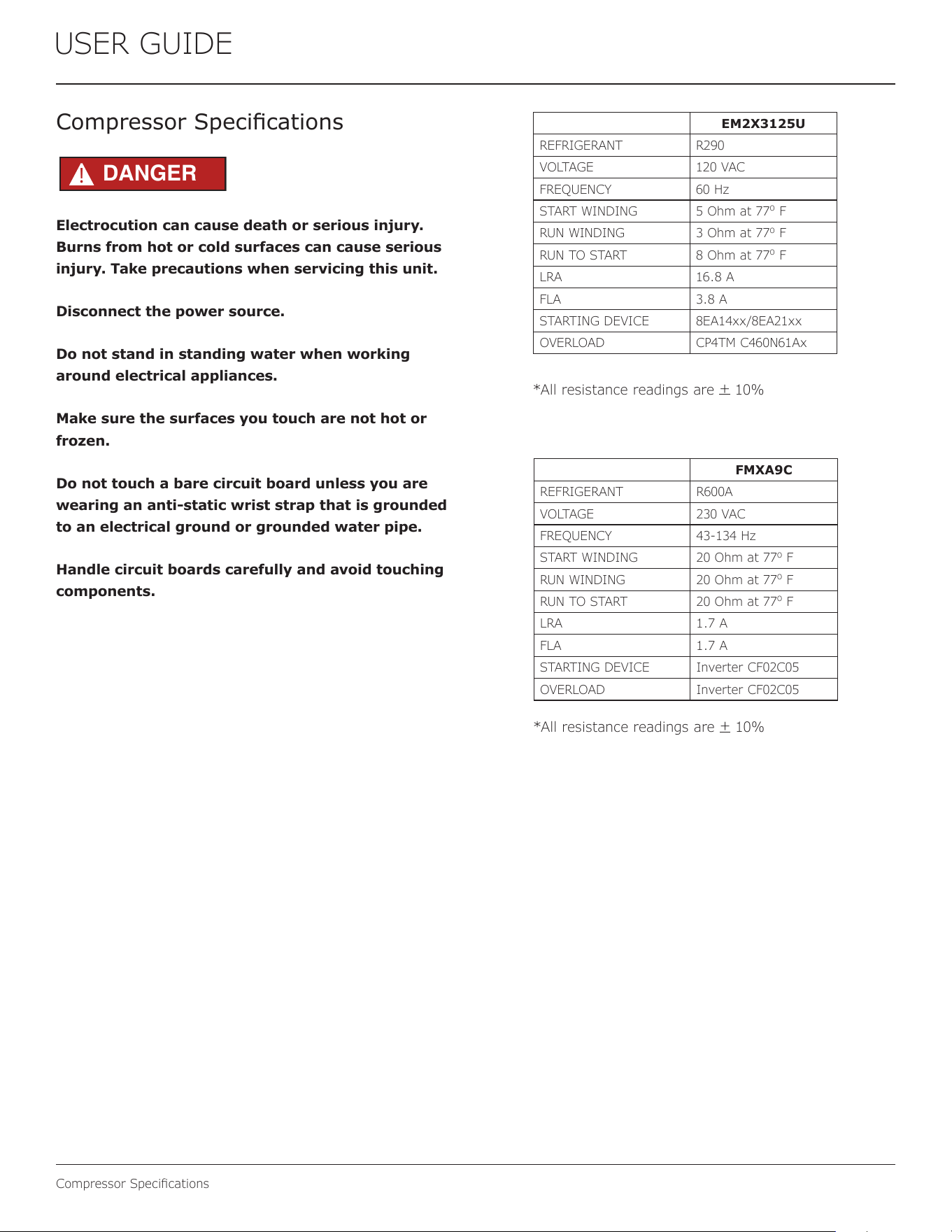
Electrocution can cause death or serious injury.
Burns from hot or cold surfaces can cause serious
injury. Take precautions when servicing this unit.
Disconnect the power source.
Do not stand in standing water when working
around electrical appliances.
Make sure the surfaces you touch are not hot or
frozen.
Do not touch a bare circuit board unless you are
wearing an anti-static wrist strap that is grounded
to an electrical ground or grounded water pipe.
Handle circuit boards carefully and avoid touching
components.
Compressor Specications
FMXA9C
REFRIGERANT R600A
VOLTAGE 230 VAC
FREQUENCY 43-134 Hz
START WINDING 20 Ohm at 77
o
F
RUN WINDING 20 Ohm at 77
o
F
RUN TO START 20 Ohm at 77
o
F
LRA 1.7 A
FLA 1.7 A
STARTING DEVICE Inverter CF02C05
OVERLOAD Inverter CF02C05
*All resistance readings are
+
10%
DANGER
!
EM2X3125U
REFRIGERANT R290
VOLTAGE 120 VAC
FREQUENCY 60 Hz
START WINDING 5 Ohm at 77
o
F
RUN WINDING 3 Ohm at 77
o
F
RUN TO START 8 Ohm at 77
o
F
LRA 16.8 A
FLA 3.8 A
STARTING DEVICE 8EA14xx/8EA21xx
OVERLOAD CP4TM C460N61Ax
*All resistance readings are
+
10%
35
USER GUIDE
Troubleshooting Extended
Troubleshooting - Extended
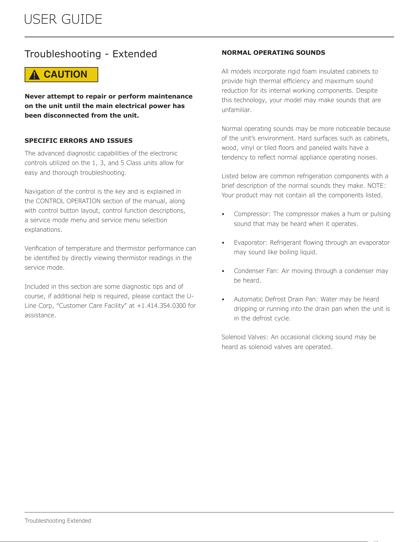
CAUTION
!
Never attempt to repair or perform maintenance
on the unit until the main electrical power has
been disconnected from the unit.
SPECIFIC ERRORS AND ISSUES
The advanced diagnostic capabilities of the electronic
controls utilized on the 1, 3, and 5 Class units allow for
easy and thorough troubleshooting.
Navigation of the control is the key and is explained in
the CONTROL OPERATION section of the manual, along
with control button layout, control function descriptions,
a service mode menu and service menu selection
explanations.
Verication of temperature and thermistor performance can
be identied by directly viewing thermistor readings in the
service mode.
Included in this section are some diagnostic tips and of
course, if additional help is required, please contact the U-
Line Corp, “Customer Care Facility” at +1.414.354.0300 for
assistance.
NORMAL OPERATING SOUNDS
All models incorporate rigid foam insulated cabinets to
provide high thermal eciency and maximum sound
reduction for its internal working components. Despite
this technology, your model may make sounds that are
unfamiliar.
Normal operating sounds may be more noticeable because
of the unit’s environment. Hard surfaces such as cabinets,
wood, vinyl or tiled oors and paneled walls have a
tendency to reect normal appliance operating noises.
Listed below are common refrigeration components with a
brief description of the normal sounds they make. NOTE:
Your product may not contain all the components listed.
• Compressor: The compressor makes a hum or pulsing
sound that may be heard when it operates.
• Evaporator: Refrigerant owing through an evaporator
may sound like boiling liquid.
• Condenser Fan: Air moving through a condenser may
be heard.
• Automatic Defrost Drain Pan: Water may be heard
dripping or running into the drain pan when the unit is
in the defrost cycle.
Solenoid Valves: An occasional clicking sound may be
heard as solenoid valves are operated.
36
USER GUIDE
Troubleshooting Extended
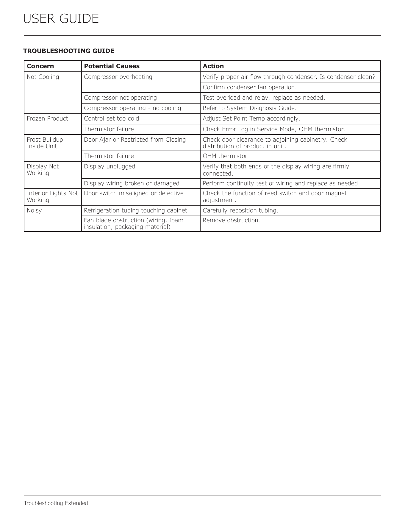
TROUBLESHOOTING GUIDE
Concern Potential Causes Action
Not Cooling Compressor overheating Verify proper air ow through condenser. Is condenser clean?
Conrm condenser fan operation.
Compressor not operating Test overload and relay, replace as needed.
Compressor operating - no cooling Refer to System Diagnosis Guide.
Frozen Product Control set too cold Adjust Set Point Temp accordingly.
Thermistor failure Check Error Log in Service Mode, OHM thermistor.
Frost Buildup
Inside Unit
Door Ajar or Restricted from Closing Check door clearance to adjoining cabinetry. Check
distribution of product in unit.
Thermistor failure OHM thermistor
Display Not
Working
Display unplugged Verify that both ends of the display wiring are rmly
connected.
Display wiring broken or damaged Perform continuity test of wiring and replace as needed.
Interior Lights Not
Working
Door switch misaligned or defective Check the function of reed switch and door magnet
adjustment.
Noisy Refrigeration tubing touching cabinet Carefully reposition tubing.
Fan blade obstruction (wiring, foam
insulation, packaging material)
Remove obstruction.
37
USER GUIDE
Troubleshooting Extended
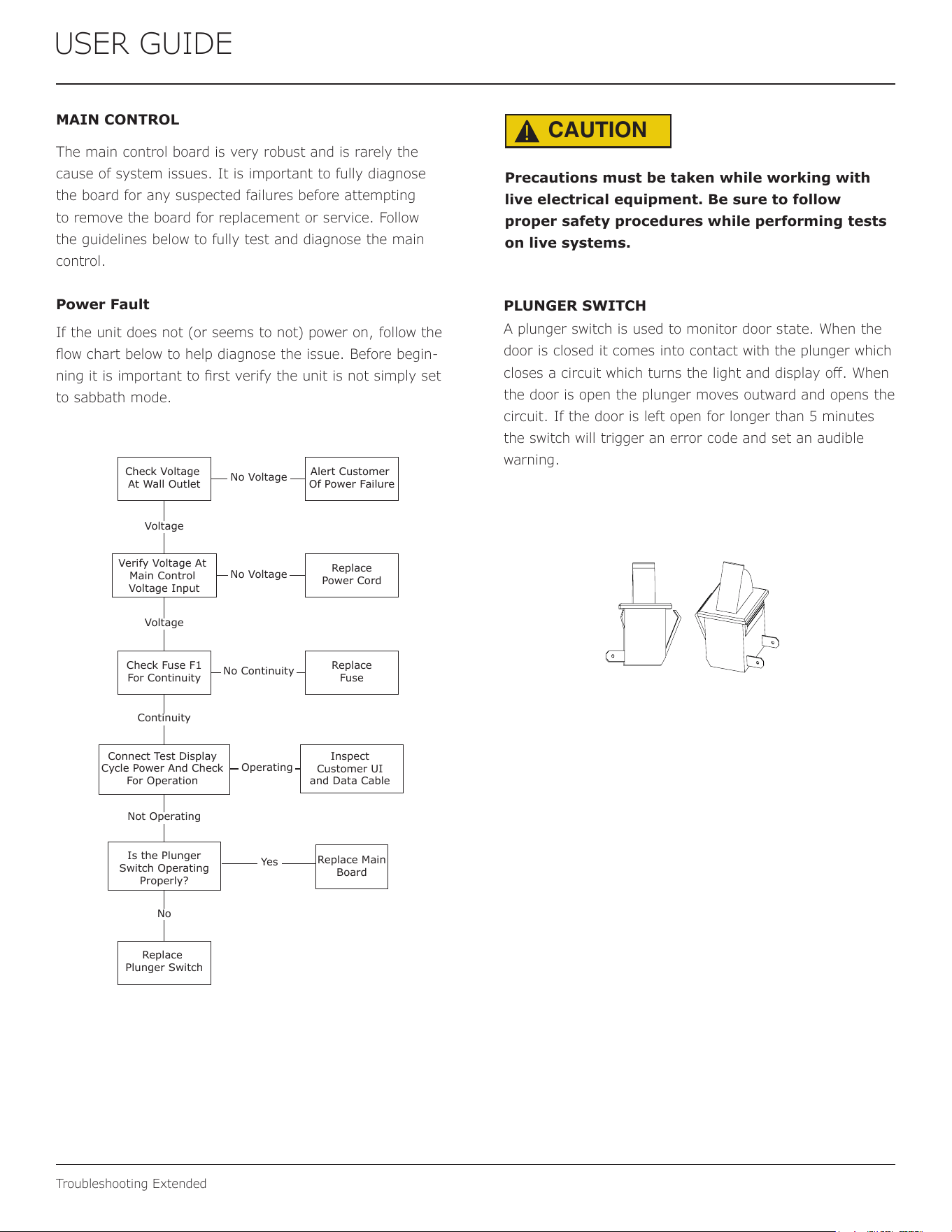
MAIN CONTROL
The main control board is very robust and is rarely the
cause of system issues. It is important to fully diagnose
the board for any suspected failures before attempting
to remove the board for replacement or service. Follow
the guidelines below to fully test and diagnose the main
control.
Power Fault
If the unit does not (or seems to not) power on, follow the
ow chart below to help diagnose the issue. Before begin-
ning it is important to rst verify the unit is not simply set
to sabbath mode.
Check Voltage
At Wall Outlet
Verify Voltage At
Main Control
Voltage Input
Check Fuse F1
For Continuity
Replace
Plunger Switch
Replace Main
Board
Replace
Fuse
Replace
Power Cord
Alert Customer
Of Power Failure
Is the Plunger
Switch Operating
Properly?
Inspect
Customer UI
and Data Cable
Connect Test Display
Cycle Power And Check
For Operation
No Voltage
No Voltage
Voltage
Continuity
Operating
Not Operating
No Continuity
No
Yes
Voltage
CAUTION
!
Precautions must be taken while working with
live electrical equipment. Be sure to follow
proper safety procedures while performing tests
on live systems.
PLUNGER SWITCH
A plunger switch is used to monitor door state. When the
door is closed it comes into contact with the plunger which
closes a circuit which turns the light and display o. When
the door is open the plunger moves outward and opens the
circuit. If the door is left open for longer than 5 minutes
the switch will trigger an error code and set an audible
warning.
38
USER GUIDE
Control Operation-Service
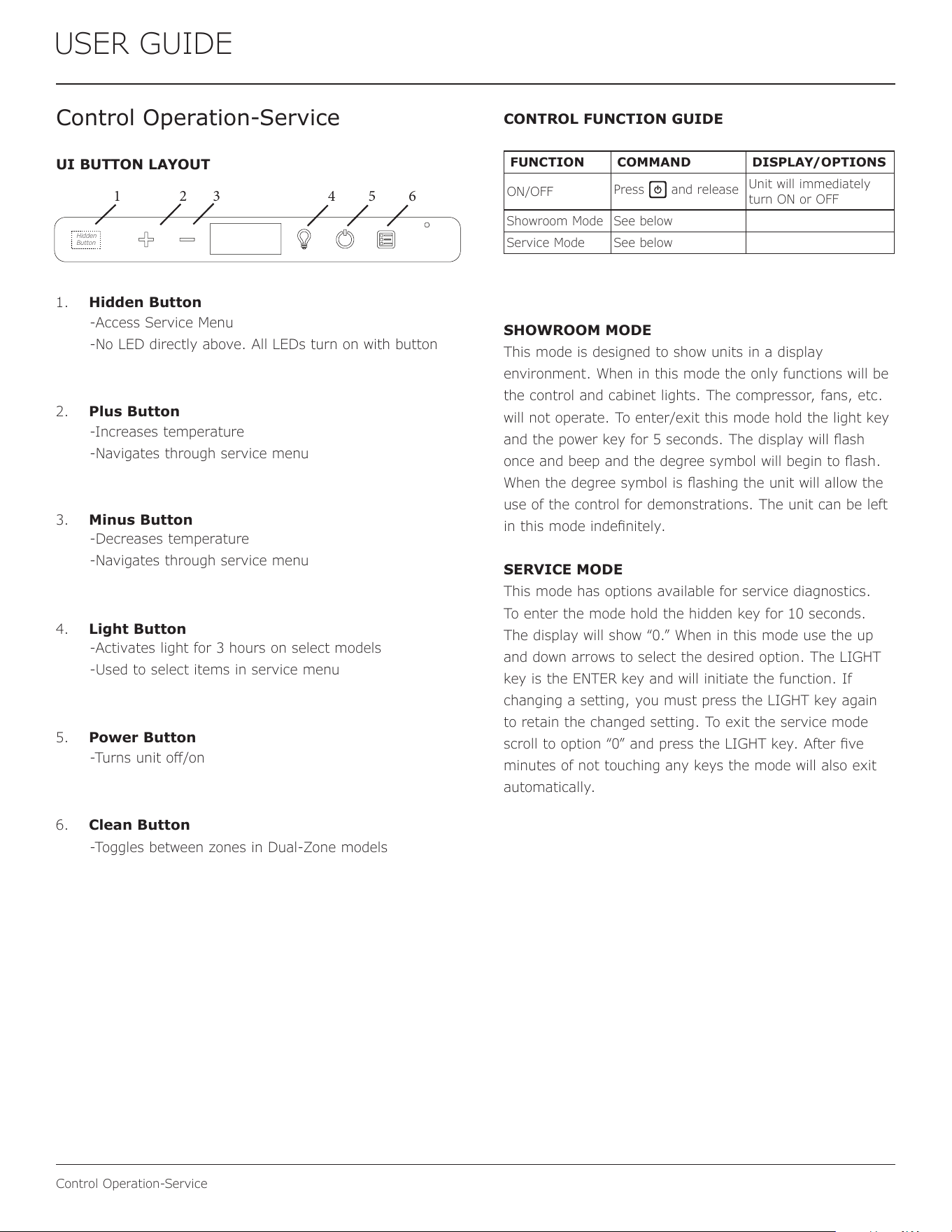
Control Operation-Service
UI BUTTON LAYOUT
1. Hidden Button
2. Plus Button
3. Minus Button
4. Light Button
5. Power Button
6. Clean Button
-Access Service Menu
-No LED directly above. All LEDs turn on with button
-Increases temperature
-Navigates through service menu
-Decreases temperature
-Navigates through service menu
-Activates light for 3 hours on select models
-Used to select items in service menu
-Turns unit o/on
-Toggles between zones in Dual-Zone models
CONTROL FUNCTION GUIDE
SHOWROOM MODE
This mode is designed to show units in a display
environment. When in this mode the only functions will be
the control and cabinet lights. The compressor, fans, etc.
will not operate. To enter/exit this mode hold the light key
and the power key for 5 seconds. The display will ash
once and beep and the degree symbol will begin to ash.
When the degree symbol is ashing the unit will allow the
use of the control for demonstrations. The unit can be left
in this mode indenitely.
SERVICE MODE
This mode has options available for service diagnostics.
To enter the mode hold the hidden key for 10 seconds.
The display will show “0.” When in this mode use the up
and down arrows to select the desired option. The LIGHT
key is the ENTER key and will initiate the function. If
changing a setting, you must press the LIGHT key again
to retain the changed setting. To exit the service mode
scroll to option “0” and press the LIGHT key. After ve
minutes of not touching any keys the mode will also exit
automatically.
1 2 3 4 5 6
FUNCTION COMMAND DISPLAY/OPTIONS
ON/OFF
Press and release
Unit will immediately
turn ON or OFF
Showroom Mode See below
Service Mode See below
Hidden
Button
39
USER GUIDE
Control Operation-Service
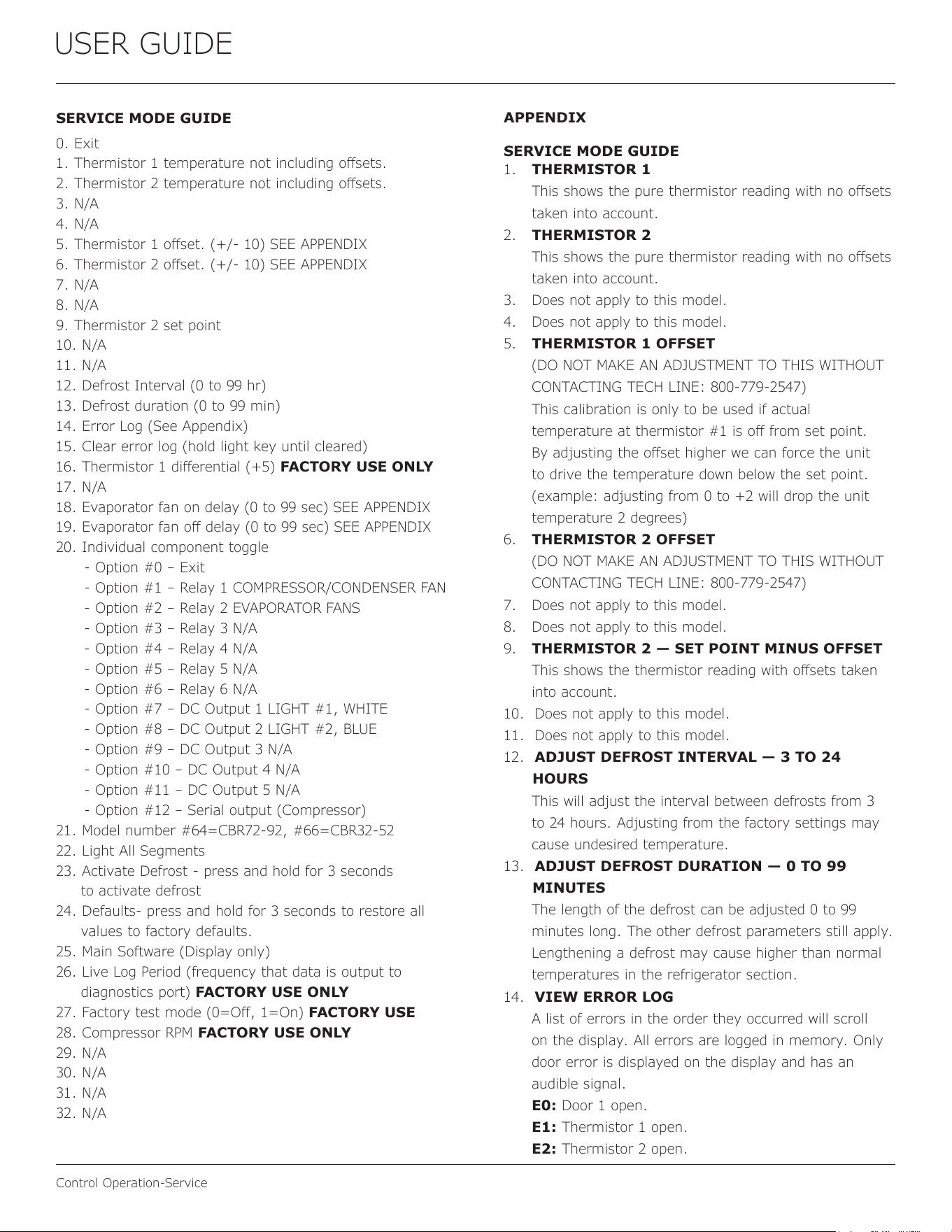
SERVICE MODE GUIDE
APPENDIX
SERVICE MODE GUIDE
0. Exit
1. Thermistor 1 temperature not including osets.
2. Thermistor 2 temperature not including osets.
3. N/A
4. N/A
5. Thermistor 1 oset. (+/- 10) SEE APPENDIX
6. Thermistor 2 oset. (+/- 10) SEE APPENDIX
7. N/A
8. N/A
9. Thermistor 2 set point
10. N/A
11. N/A
12. Defrost Interval (0 to 99 hr)
13. Defrost duration (0 to 99 min)
14. Error Log (See Appendix)
15. Clear error log (hold light key until cleared)
16. Thermistor 1 dierential (+5) FACTORY USE ONLY
17. N/A
18. Evaporator fan on delay (0 to 99 sec) SEE APPENDIX
19. Evaporator fan o delay (0 to 99 sec) SEE APPENDIX
20. Individual component toggle
- Option #0 – Exit
- Option #1 – Relay 1 COMPRESSOR/CONDENSER FAN
- Option #2 – Relay 2 EVAPORATOR FANS
- Option #3 – Relay 3 N/A
- Option #4 – Relay 4 N/A
- Option #5 – Relay 5 N/A
- Option #6 – Relay 6 N/A
- Option #7 – DC Output 1 LIGHT #1, WHITE
- Option #8 – DC Output 2 LIGHT #2, BLUE
- Option #9 – DC Output 3 N/A
- Option #10 – DC Output 4 N/A
- Option #11 – DC Output 5 N/A
- Option #12 – Serial output (Compressor)
21. Model number #64=CBR72-92, #66=CBR32-52
22. Light All Segments
23. Activate Defrost - press and hold for 3 seconds
to activate defrost
24. Defaults- press and hold for 3 seconds to restore all
values to factory defaults.
25. Main Software (Display only)
26. Live Log Period (frequency that data is output to
diagnostics port) FACTORY USE ONLY
27. Factory test mode (0=O, 1=On) FACTORY USE
28. Compressor RPM FACTORY USE ONLY
29. N/A
30. N/A
31. N/A
32. N/A
1. THERMISTOR 1
This shows the pure thermistor reading with no osets
taken into account.
2. THERMISTOR 2
This shows the pure thermistor reading with no osets
taken into account.
3. Does not apply to this model.
4. Does not apply to this model.
5. THERMISTOR 1 OFFSET
(DO NOT MAKE AN ADJUSTMENT TO THIS WITHOUT
CONTACTING TECH LINE: 800-779-2547)
This calibration is only to be used if actual
temperature at thermistor #1 is o from set point.
By adjusting the oset higher we can force the unit
to drive the temperature down below the set point.
(example: adjusting from 0 to +2 will drop the unit
temperature 2 degrees)
6. THERMISTOR 2 OFFSET
(DO NOT MAKE AN ADJUSTMENT TO THIS WITHOUT
CONTACTING TECH LINE: 800-779-2547)
7. Does not apply to this model.
8. Does not apply to this model.
9. THERMISTOR 2 — SET POINT MINUS OFFSET
This shows the thermistor reading with osets taken
into account.
10. Does not apply to this model.
11. Does not apply to this model.
12. ADJUST DEFROST INTERVAL — 3 TO 24
HOURS
This will adjust the interval between defrosts from 3
to 24 hours. Adjusting from the factory settings may
cause undesired temperature.
13. ADJUST DEFROST DURATION — 0 TO 99
MINUTES
The length of the defrost can be adjusted 0 to 99
minutes long. The other defrost parameters still apply.
Lengthening a defrost may cause higher than normal
temperatures in the refrigerator section.
14. VIEW ERROR LOG
A list of errors in the order they occurred will scroll
on the display. All errors are logged in memory. Only
door error is displayed on the display and has an
audible signal.
E0: Door 1 open.
E1: Thermistor 1 open.
E2: Thermistor 2 open.
40
USER GUIDE
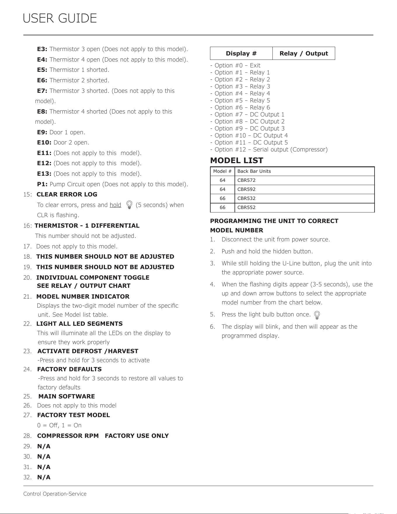
Control Operation-Service
E3: Thermistor 3 open (Does not apply to this model).
E4: Thermistor 4 open (Does not apply to this model).
E5: Thermistor 1 shorted.
E6: Thermistor 2 shorted.
E7: Thermistor 3 shorted. (Does not apply to this
model).
E8: Thermistor 4 shorted (Does not apply to this
model).
E9: Door 1 open.
E10: Door 2 open.
E11: (Does not apply to this model).
E12: (Does not apply to this model).
E13: (Does not apply to this model).
P1: Pump Circuit open (Does not apply to this model).
15: CLEAR ERROR LOG
To clear errors, press and hold (5 seconds) when
CLR is ashing.
16: THERMISTOR - 1 DIFFERENTIAL
This number should not be adjusted.
17. Does not apply to this model.
18. THIS NUMBER SHOULD NOT BE ADJUSTED
19. THIS NUMBER SHOULD NOT BE ADJUSTED
20. INDIVIDUAL COMPONENT TOGGLE
21. MODEL NUMBER INDICATOR
Displays the two-digit model number of the specic
unit. See Model list table.
22. LIGHT ALL LED SEGMENTS
This will illuminate all the LEDs on the display to
ensure they work properly
23. ACTIVATE DEFROST /HARVEST
-Press and hold for 3 seconds to activate
24. FACTORY DEFAULTS
-Press and hold for 3 seconds to restore all values to
factory defaults
25. MAIN SOFTWARE
26. Does not apply to this model
27. FACTORY TEST MODEL
0 = O, 1 = On
28. COMPRESSOR RPM FACTORY USE ONLY
29. N/A
30. N/A
31. N/A
32. N/A
Display # Relay / Output
- Option #0 – Exit
- Option #1 – Relay 1
- Option #2 – Relay 2
- Option #3 – Relay 3
- Option #4 – Relay 4
- Option #5 – Relay 5
- Option #6 – Relay 6
- Option #7 – DC Output 1
- Option #8 – DC Output 2
- Option #9 – DC Output 3
- Option #10 – DC Output 4
- Option #11 – DC Output 5
- Option #12 – Serial output (Compressor)
SEE RELAY / OUTPUT CHART
PROGRAMMING THE UNIT TO CORRECT
MODEL NUMBER
1. Disconnect the unit from power source.
2. Push and hold the hidden button.
3. While still holding the U-Line button, plug the unit into
the appropriate power source.
4. When the ashing digits appear (3-5 seconds), use the
up and down arrow buttons to select the appropriate
model number from the chart below.
5. Press the light bulb button once.
6. The display will blink, and then will appear as the
programmed display.
Model # Back Bar Units
64 CBR572
64 CBR592
66 CBR532
66 CBR552
MODEL LIST
41
USER GUIDE
Control Operation-Service
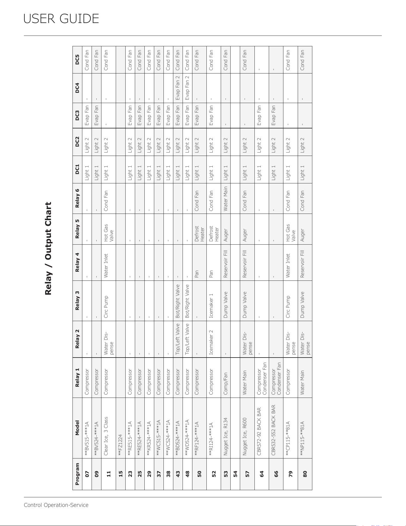
Program Model Relay 1 Relay 2 Relay 3 Relay 4 Relay 5 Relay 6 DC1 DC2 DC3 DC4 DC5
07
**BV515-***1A Compressor - - - - - Light 1 Light 2 Evap Fan - Cond Fan
09
**BV524-***1A Compressor - - - - - Light 1 Light 2 Evap Fan - Cond Fan
11
Clear Ice, 3 Class Compressor Water Dis-
pense
Circ Pump Water Inlet Hot Gas
Valve
Cond Fan Light 1 Light 2 - - Cond Fan
15
**FZ1224
23
**RE515-***1A Compressor - - - - - Light 1 Light 2 Evap Fan - Cond Fan
25
**RE524-***1A Compressor - - - - - Light 1 Light 2 Evap Fan - Cond Fan
29
**KR524-***1A Compressor - - - - - Light 1 Light 2 Evap Fan - Cond Fan
37
**WC515-***1A Compressor - - - - - Light 1 Light 2 Evap Fan - Cond Fan
38
**WC524-***1A Compressor - - - - - Light 1 Light 2 Evap Fan - Cond Fan
43
**BD524-***1A Compressor Top/Left Valve Bot/Right Valve - - - Light 1 Light 2 Evap Fan Evap Fan 2 Cond Fan
48
**WD524-***1A Compressor Top/Left Valve Bot/Right Valve - - - Light 1 Light 2 Evap Fan Evap Fan 2 Cond Fan
50
**RF124-***1A Compressor - - Pan Defrost
Heater
Cond Fan Light 1 Light 2 Evap Fan - Cond Fan
52
**RI124-***1A Compressor Icemaker 2 Icemaker 1 Pan Defrost
Heater
Cond Fan Light 1 Light 2 Evap Fan - Cond Fan
53
Nugget Ice, R134 Comp/Fan - Dump Valve Reservoir Fill Auger Water Main Light 1 Light 2 - - Cond Fan
54
57
Nugget Ice, R600 Water Main Water Dis-
pense
Dump Valve Reservoir Fill Auger Cond Fan Light 1 Light 2 - - Cond Fan
64
CBR572-92 BACK BAR Compressor
Condenser Fan
- - - - - Light 1 Light 2 Evap Fan - -
66
CBR532-552 BACK BAR Compressor
Condenser Fan
- - - - - Light 1 Light 2 Evap Fan - -
79
**CP115-**81A Compressor Water Dis-
pense
Circ Pump Water Inlet Hot Gas
Valve
Cond Fan Light 1 Light 2 - - Cond Fan
80
**NP115-**81A Water Main Water Dis-
pense
Dump Valve Reservoir Fill Auger Cond Fan Light 1 Light 2 - - Cond Fan
Relay / Output Chart
42
USER GUIDE
Thermistor
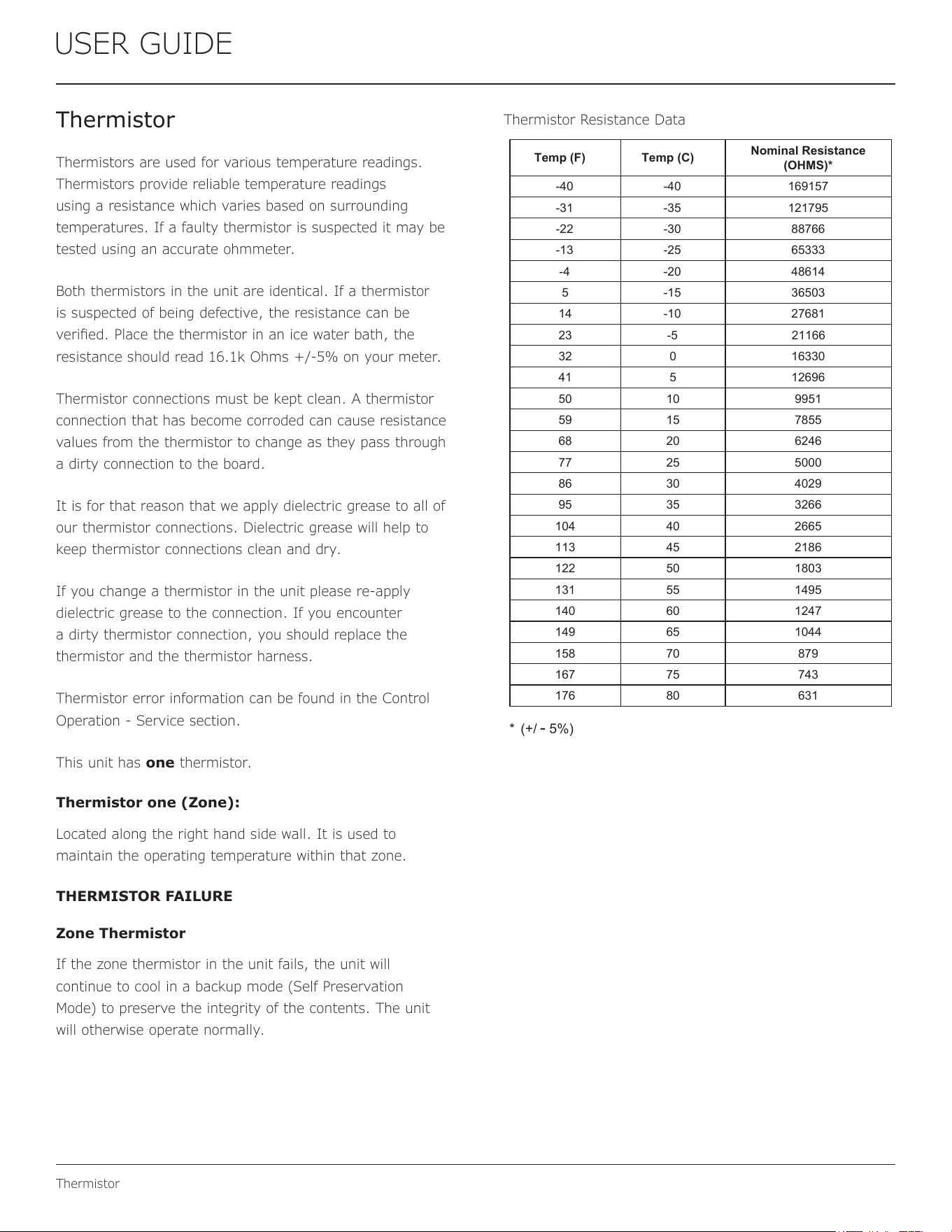
Thermistor Resistance Data
Thermistor
Thermistors are used for various temperature readings.
Thermistors provide reliable temperature readings
using a resistance which varies based on surrounding
temperatures. If a faulty thermistor is suspected it may be
tested using an accurate ohmmeter.
Both thermistors in the unit are identical. If a thermistor
is suspected of being defective, the resistance can be
veried. Place the thermistor in an ice water bath, the
resistance should read 16.1k Ohms +/-5% on your meter.
Thermistor connections must be kept clean. A thermistor
connection that has become corroded can cause resistance
values from the thermistor to change as they pass through
a dirty connection to the board.
It is for that reason that we apply dielectric grease to all of
our thermistor connections. Dielectric grease will help to
keep thermistor connections clean and dry.
If you change a thermistor in the unit please re-apply
dielectric grease to the connection. If you encounter
a dirty thermistor connection, you should replace the
thermistor and the thermistor harness.
Thermistor error information can be found in the Control
Operation - Service section.
This unit has one thermistor.
Thermistor one (Zone):
Located along the right hand side wall. It is used to
maintain the operating temperature within that zone.
THERMISTOR FAILURE
Zone Thermistor
If the zone thermistor in the unit fails, the unit will
continue to cool in a backup mode (Self Preservation
Mode) to preserve the integrity of the contents. The unit
will otherwise operate normally.
USER GUIDE
u-line.com
Thermistor
Thermistor Resistance Data
Thermistor
Thermistors are used for various temperature readings.
Thermistors provide reliable temperature readings using a
resistance which varies based on surrounding temperatures. If a
faulty thermistor is suspected, it may be tested using an
accurate ohmmeter.
Thermistor connections must be kept clean. A thermistor
connection that has become corroded can cause resistance
values from the thermistor to change as they pass through a
dirty connection to the board.
It is for that reason that we apply dielectric grease to all of our
thermistor connections. Dielectric grease will help to keep
thermistor connections clean and dry.
If you change a thermistor in the unit, please re-apply dielectric
grease to the connection. If you encounter a dirty thermistor
connection, you should replace the thermistor and the
thermistor harness.
This unit has one thermistor located along the right hand
sidewall of the ice bin. It is used to maintain the ice level in the
bin.
Temp (F) Temp (C)
Nominal Resistance
(OHMS)*
-40 -40 169157
-31 -35 121795
-22 -30 88766
-13 -25 65333
-4 -20 48614
5 -15 36503
14 -10 27681
23 -5
21166
32 0 16330
41 5 12696
50 10 9951
59 15 7855
68 20 6246
77 25 5000
86 30 4029
95 35 3266
104 40 2665
113 45 2186
122 50 1803
131 55 1495
140 60 1247
149 65 1044
158 70 879
167 75 743
176 80 631
*
(+/
-
5%)
43
USER GUIDE
Defrost
Defrost
If you have veried that the unit does not have an
ambient air leak, utilize the Control Operation -
Service section and adjust unit to defrost longer
and/or more/less often as needed.
44
USER GUIDE
Remove Fan and Cover
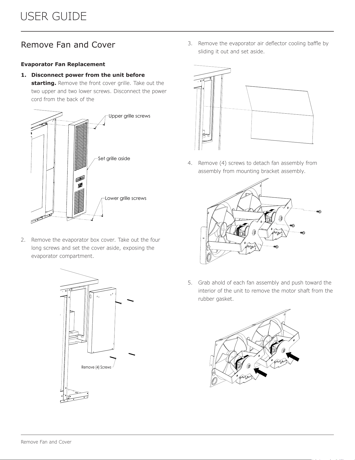
Remove Fan and Cover
Evaporator Fan Replacement
1. Disconnect power from the unit before
starting. Remove the front cover grille. Take out the
two upper and two lower screws. Disconnect the power
cord from the back of the
2. Remove the evaporator box cover. Take out the four
long screws and set the cover aside, exposing the
evaporator compartment.
3. Remove the evaporator air deector cooling bae by
sliding it out and set aside.
4. Remove (4) screws to detach fan assembly from
assembly from mounting bracket assembly.
5. Grab ahold of each fan assembly and push toward the
interior of the unit to remove the motor shaft from the
rubber gasket.
Upper grille screws
Lower grille screws
Set grille aside
Remove (4) Screws
45
USER GUIDE
Remove Fan and Cover
6. Once the shaft is free of the gasket, rotate the fan
assembly upward and out toward you and away
from the mounting bracket.
7. Installation is the reverse of removal.
8. Take special care to properly route wires away from
fans and copper tubing and make sure fan motor is
secured in rubber gasket.
9. Use sealant gum to seal any openings at rear of unit
before replacing covers.
10. Reinstall unit taking care to level, space and secure as
found.
46
ENSURING YOUR WARRANTY STAYS VALID
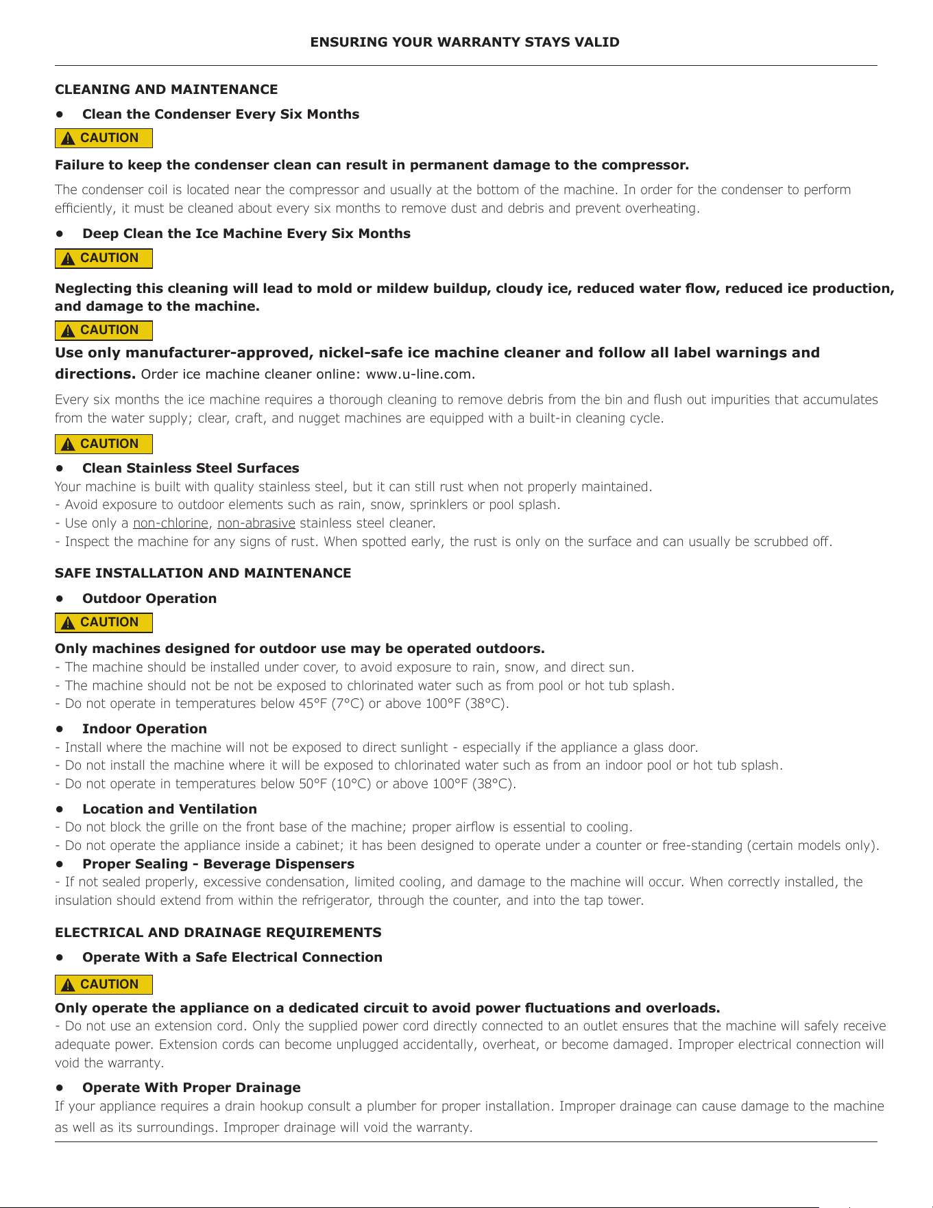
CLEANING AND MAINTENANCE
• Clean the Condenser Every Six Months
Failure to keep the condenser clean can result in permanent damage to the compressor.
The condenser coil is located near the compressor and usually at the bottom of the machine. In order for the condenser to perform
eciently, it must be cleaned about every six months to remove dust and debris and prevent overheating.
• Deep Clean the Ice Machine Every Six Months
Neglecting this cleaning will lead to mold or mildew buildup, cloudy ice, reduced water ow, reduced ice production,
and damage to the machine.
Use only manufacturer-approved, nickel-safe ice machine cleaner and follow all label warnings and
directions. Order ice machine cleaner online: www.u-line.com.
Every six months the ice machine requires a thorough cleaning to remove debris from the bin and ush out impurities that accumulates
from the water supply; clear, craft, and nugget machines are equipped with a built-in cleaning cycle.
• Clean Stainless Steel Surfaces
Your machine is built with quality stainless steel, but it can still rust when not properly maintained.
- Avoid exposure to outdoor elements such as rain, snow, sprinklers or pool splash.
- Use only a non-chlorine, non-abrasive stainless steel cleaner.
- Inspect the machine for any signs of rust. When spotted early, the rust is only on the surface and can usually be scrubbed o.
SAFE INSTALLATION AND MAINTENANCE
• Outdoor Operation
Only machines designed for outdoor use may be operated outdoors.
- The machine should be installed under cover, to avoid exposure to rain, snow, and direct sun.
- The machine should not be not be exposed to chlorinated water such as from pool or hot tub splash.
- Do not operate in temperatures below 45°F (7°C) or above 100°F (38°C).
• Indoor Operation
- Install where the machine will not be exposed to direct sunlight - especially if the appliance a glass door.
- Do not install the machine where it will be exposed to chlorinated water such as from an indoor pool or hot tub splash.
- Do not operate in temperatures below 50°F (10°C) or above 100°F (38°C).
• Location and Ventilation
- Do not block the grille on the front base of the machine; proper airow is essential to cooling.
- Do not operate the appliance inside a cabinet; it has been designed to operate under a counter or free-standing (certain models only).
• Proper Sealing - Beverage Dispensers
- If not sealed properly, excessive condensation, limited cooling, and damage to the machine will occur. When correctly installed, the
insulation should extend from within the refrigerator, through the counter, and into the tap tower.
ELECTRICAL AND DRAINAGE REQUIREMENTS
• Operate With a Safe Electrical Connection
Only operate the appliance on a dedicated circuit to avoid power uctuations and overloads.
- Do not use an extension cord. Only the supplied power cord directly connected to an outlet ensures that the machine will safely receive
adequate power. Extension cords can become unplugged accidentally, overheat, or become damaged. Improper electrical connection will
void the warranty.
• Operate With Proper Drainage
If your appliance requires a drain hookup consult a plumber for proper installation. Improper drainage can cause damage to the machine
as well as its surroundings. Improper drainage will void the warranty.
CAUTION
!
CAUTION
!
CAUTION
!
CAUTION
!
CAUTION
!
CAUTION
!
47
Middleby Refrigeration | 1260 E. Van Deinse, Greenville, MI 48838
Middleby Refrigeration Limited Warranty
THREE YEAR LIMITED PARTS & LABOR WARRANTY – Viking Commercial and U-Line Commercial
For three years from the date of shipment from the factory this warranty covers all parts and labor to repair or replace any part of
the referenced Middleby Refrigeration product (the “Equipment”) that under normal use proves to be defective in materials or
workmanship. This warranty is conditioned upon you promptly notifying Middleby Refrigeration of any claims, and providing
Middleby Refrigeration with all data and information requested by Middleby Refrigeration or its service agents in connection with
such claims as well as all necessary access to your premises and the Equipment. All service provided by Middleby Refrigeration
under the above warranty must be performed by a Middleby Refrigeration factory authorized servicer and dispatched from the
factory, unless otherwise specified by Middleby Refrigeration. Warranty labor is provided at straight time only.
LIMITED FIVE YEAR SEALED SYSTEM PARTS WARRANTY – Viking Commercial and U-Line Commercial
For five years from the date of original purchase, Middleby Refrigeration will cover the following parts only(no labor) if they prove to
be defective under normal commercial use: compressor.
WARRANTY TERMS
These warranties apply only to Equipment installed in any one of the fifty states of the United States, the District of Columbia, or
the ten provinces of Canada. The Equipment must be installed, operated, and maintained in accordance with Middleby
Refrigeration Brand User, Installation and Service Guides, copies of which were provided to you with the Equipment or otherwise
will be furnished to you upon request. Further, this warranty applies only to Equipment shipped from the Middleby Refrigeration
facility after July 1, 2025 and purchased from an authorized dealer.
Except as provided in the Limited Warranty above, the Equipment is provided “as-is”. Middleby Refrigeration disclaims all other
warranties, express, statutory or implied, including without limitation, the implied warranties of title, non-infringement,
merchantability and fitness for a particular purpose. Middleby Refrigeration does not warrant that the Equipment will meet your
specifications or needs. You acknowledge that you are solely responsible for the selection of the Equipment and determining the
suitability of the Equipment for your needs.The warranties only apply to the original purchaser and are non-transferable. Service
must be dispatched from Middleby Refrigeration to be eligible for warranty coverage. The warranties apply to units operated
outside only if designed for outdoor use by model and serial number. Replacement water filters, light bulbs, and other
consumable parts are not covered by these warranties. In-home/business instruction on how to use your product is not covered
by these warranties. Food, beverage, and medicine loss are not covered by these warranties. Use of non OEM parts will void this
warranty.
If the Equipment is located in an area where Middleby Refrigeration factory authorized service is not available, you may be
responsible for a trip charge or you may be required to bring the Equipment to a Middleby Refrigeration factory authorized service
location at your own cost and expense.
Units purchased after use as floor displays, and/or certified reconditioned units, are covered by the limited one year warranty only
and no coverage is provided for cosmetic defects.
To maintain warranty coverage, all preventative maintenance procedures outlined in the Use and Care Manual must be followed.
Signal issues related to Wi-Fi connectivity are not covered by these warranties.
Equipment that is not installed, operated and maintained in accordance with Middleby Refrigeration’s Use and Care Manual or
other written materials provided to you by Middleby Refrigeration or available for the Equipment (as may be updated by Middleby
Refrigeration from time to time, the “Manual”), a copy of which is provided to you with the Equipment or otherwise will be
furnished to you upon request, is excluded from this warranty. This warranty does not apply to damage or failure which results, in
48
Middleby Refrigeration | 1260 E. Van Deinse, Greenville, MI 48838
Middleby Refrigeration’s or its service agent’s sole opinion, from failure to provide a suitable installation and operating
environment (including power and HVAC if applicable) and facilities as prescribed by the Manual, misuse, abuse, accident or
improper use, neglect, power failure or power surges (over or under voltage), or to damage or failure from flood, fire, lightning or
other natural or man-made disasters, or other Acts of God, or to Equipment that has missing or altered serial numbers.
Modifications and Repair: Equipment that has been modified or altered by persons other than Middleby Refrigeration’s or its
service agents, or Equipment that has had non-approved devices or connection items attached thereto, is excluded from coverage
under this warranty. Repair of the Equipment by anyone other than Middleby Refrigeration’s or its authorized service agents will
void all warranties on the Equipment.
Accessories: Accessories and parts (collectively “Accessories”) that are consumed in the normal course of Equipment operation
or maintenance are excluded from this warranty. Failure of or damage to Equipment or components from the use of non-approved
cleaning chemicals, devices or processes is also excluded from this warranty.
Warranty Service, Exclusive Remedy
Middleby Refrigeration will be solely responsible for determining whether or not the Equipment or any component thereof is
defective. Defective components covered by this warranty will be repaired or replaced at Middleby Refrigeration’s option without
charge to you and such repaired or replacement components will be covered by this warranty for the balance of the Warranty
Period. Parts used in the repair of defective components and replacement components may be new, recovered or rebuilt. At its
sole option, Middleby Refrigeration may decide to replace defective Equipment covered by this warranty with new, recovered or
rebuilt Equipment of equal or greater capability, and such Equipment will be covered by this Limited Warranty for the balance of
the Warranty Period. Defective Equipment and components will become the property of Middleby Refrigeration. This paragraph
states Middleby Refrigeration’s sole and exclusive obligation and liability and your sole and exclusive remedy under this warranty.
Middleby Refrigeration shall not be responsible for a failure to provide warranty services due to causes beyond Middleby
Refrigeration’s or its service agents’ control.
Warranty Claims
Claims under this warranty must be reported to Middleby Refrigeration under such reporting service as Middleby Refrigeration
may designate. Upon receipt of the claim and related information and preliminary verification that the claim is valid, Middleby
Refrigeration will promptly notify an authorized service agent to contact you and arrange for an on-site repair visit during the
service agent’s normal working hours. Any costs incurred by Middleby Refrigeration or its service agent associated with a service
agent being refused or unable to gain access to the Equipment on your premises, or a claim not covered by this warranty, will be
charged to you.
Disclaimer of Damages
Middleby Refrigeration disclaims all incidental, special and consequential damages, including but not limited to loss of use, lost
revenue or profits, or substitute use, suffered by you or any third party, whether arising in contract, tort (including negligence), or
otherwise, resulting from any breach by Middleby Refrigeration or its service agents of this warranty, or resulting from the
manufacture, use, or defects, of or in the Equipment, even if Middleby Refrigeration was apprised of the possibility of such
damages.
Customer Indemnity
You agree to indemnify, defend and hold Middleby Refrigeration harmless from all third party claims, demands, judgments, fees
and costs directly or indirectly arising out of or related to your use of the Equipment. You further agree to indemnify and hold
Middleby Refrigeration harmless from any incidental, consequential or special damages suffered by you, including lost revenue or
profits, loss of use, or substitute use, during periods of Equipment failure or loss of use.
Governing Law, Entire Warranty
49
Middleby Refrigeration | 1260 E. Van Deinse, Greenville, MI 48838
This warranty shall be governed and construed in accordance with the laws of the State of Michigan, USA (except with respect to
its provisions regarding conflicts of laws). The warranty described herein is the complete and only warranty for Equipment and
supersedes all prior oral or written agreements and understandings that may have existed between us relating to Equipment
warranties. The terms of this warranty may not be altered, amended or modified except by a signed writing from Middleby
Refrigeration. Any purported alteration, amendment or modification by a service agent or anyone else will not be enforceable
against Middleby Refrigeration.
Charges for Non-Warranty Service or Rejection of Service Visit
In the event that repairs, replacement or service are provided by Middleby Refrigeration’s service agents for work not covered by
this limited warranty, customer agrees to pay the service agent directly according to the service agent’s normal scale of charges. In
the event Middleby Refrigeration is invoiced by the service agent for services not covered under this extended warranty, Middleby
Refrigeration will invoice customer and customer will pay such invoice based on terms of net 10 days. Customer also agrees to pay
any cost incurred by Middleby Refrigeration or its service agent associated with a service agent responding to a call for service, but
then being refused or unable to gain access to the Equipment on Customer’s premises. Failure to submit payment may, at
Middleby Refrigeration’s discretion, result in Middleby Refrigeration voiding the balance of the warranty. In no event will Middleby
Refrigeration authorize service to a customer with an outstanding Non-Warranty invoice.
For parts and service assistance, or to find factory authorized service near you, contact Middleby Refrigeration at 616.754.5601.
7-1-2025 #30757 REV_A
50