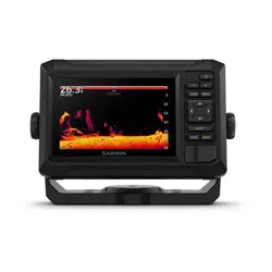
ECHOMAP
™
UHD2 5X/7X
Owner’s Manual

© 2022 Garmin Ltd. or its subsidiaries
All rights reserved. Under the copyright laws, this manual may not be copied, in whole or in part, without the written consent of Garmin. Garmin reserves the right to change
or improve its products and to make changes in the content of this manual without obligation to notify any person or organization of such changes or improvements. Go to
www.garmin.com for current updates and supplemental information concerning the use of this product.
Garmin
®
, the Garmin logo, ActiveCaptain
®
, and BlueChart
®
are trademarks of Garmin Ltd. or its subsidiaries, registered in the USA and other countries. ECHOMAP
™
, Garmin
ClearVü
™
, Garmin Connect
™
, Garmin Express
™
, Garmin LakeVü
™
, Garmin Quickdraw
™
, Garmin Navionics Vision+
™
, Panoptix
™
, and OneChart
™
are trademarks of Garmin Ltd. or its
subsidiaries. These trademarks may not be used without the express permission of Garmin.
Mac
®
is a trademark of Apple Inc., registered in the U.S. and other countries. microSD
®
and the microSD logo are trademarks of SD-3C, LLC. Standard Mapping
®
is a trademark of
Standard Mapping Service, LLC. Wi‑Fi
®
is a registered mark of Wi-Fi Alliance Corporation. Windows
®
is a registered trademark of Microsoft Corporation in the United States and other
countries. All other trademarks and copyrights are the property of their respective owners.

Table of Contents
Introduction......................................1
Front View................................................ 1
Device Keys..........................................2
Connector View....................................... 2
Tips and Shortcuts.................................. 3
Accessing Owner's Manuals on the
Chartplotter..............................................3
Accessing the Manuals from the
Web.......................................................... 3
Garmin Support Center........................... 3
Inserting Memory Cards......................... 4
Acquiring GPS Satellite Signals..............4
Selecting the GPS Source................... 4
Customizing the Chartplotter............5
Home Screen........................................... 5
Rearranging the Category Items.........5
Customizing Pages................................. 6
Customizing with Combination
Pages................................................... 6
Creating a New Combination Page.... 6
Deleting a Combination Page............. 6
Customizing the Data Overlays.......... 7
Adjusting the Backlight....................... 7
Adjusting the Color Mode................... 7
Adjusting the Color Theme................. 7
Turning On the Chartplotter
Automatically....................................... 7
Automatically Turning Off the
System................................................. 7
Customizing the Startup Screen.........8
ActiveCaptain® App......................... 8
ActiveCaptain Roles................................ 8
Getting Started with the ActiveCaptain
App........................................................... 9
Updating Software with the
ActiveCaptain App...................................9
Updating Charts with ActiveCaptain.... 10
Chart Subscriptions.............................. 10
Wireless Sharing............................ 10
Setting Up the Wi‑Fi Network............... 10
Connecting Two Compatible
ECHOMAP Devices to Share User Data
and Sonar........................................... 11
Connecting a Wireless Device to the
Chartplotter........................................ 11
Managing the Wi‑Fi Network............ 12
Charts and 3D Chart Views............. 12
Detailed Charts...................................... 12
Activating a Marine Chart
Subscription.......................................13
Purchasing a Chart Subscription with
ActiveCaptain.................................... 13
Renewing Your Subscription............ 13
Navigation Chart and Fishing Chart..... 14
Chart Symbols................................... 14
Zooming In and Out of the Chart...... 14
Panning the Chart with the Keys...... 15
Selecting an Item on the Map Using
the Device Keys................................. 15
Measuring a Distance on the
Chart................................................... 15
Creating a Waypoint on the Chart.... 15
Viewing Location and Object
Information on a Chart...................... 15
Viewing Details about Navaids.........15
Navigating to a Point on the Chart... 16
Premium Chart Features...................... 17
Fish Eye 3D Chart View..................... 18
Viewing Tide Station Information.....18
Showing Satellite Imagery on the
Navigation Chart................................19
Viewing Aerial Photos of
Landmarks......................................... 20
Chart Menu............................................ 20
Chart Layers.......................................20
Chart Settings.................................... 23
Fish Eye 3D Settings......................... 23
Supported Maps.................................... 23
Garmin Quickdraw Contours
Mapping......................................... 24
Mapping a Body of Water Using the
Garmin Quickdraw Contours Feature.. 24
Adding a Label to a Garmin Quickdraw
Contours Map........................................ 24
Garmin Quickdraw Community............ 25
Table of Contents i

Connecting to the Garmin Quickdraw
Community with ActiveCaptain........ 25
Garmin Quickdraw Contours
Settings.................................................. 26
Navigation with a Chartplotter........ 26
Basic Navigation Questions................. 27
Route Color Coding............................... 27
Destinations.......................................... 27
Searching for a Destination by
Name.................................................. 28
Selecting a Destination Using the
Navigation Chart................................28
Searching for a Marine Services
Destination.........................................28
Setting and Following a Direct Course
Using Go To....................................... 28
Stopping Navigation..........................28
Waypoints.............................................. 29
Marking Your Present Location as a
Waypoint............................................ 29
Creating a Waypoint at a Different
Location............................................. 29
Marking an MOB Location................ 29
Projecting a Waypoint....................... 29
Viewing a List of all Waypoints........ 29
Editing a Saved Waypoint................. 29
Moving a Saved Waypoint................ 30
Browsing for and Navigating to a
Saved Waypoint................................. 30
Deleting a Waypoint or an MOB........30
Deleting All Waypoints...................... 30
Routes.................................................... 31
Creating and Navigating a Route From
Your Present Location...................... 31
Creating and Saving a Route............ 31
Viewing a List of Routes and Auto
Guidance Paths................................. 31
Editing a Saved Route....................... 31
Finding and Navigating a Saved
Route.................................................. 32
Browsing for and Navigating Parallel
to a Saved Route............................... 32
Initiating a Search Pattern................ 33
Deleting a Saved Route..................... 33
Deleting All Saved Routes................. 33
Auto Guidance....................................... 33
Setting and Following an Auto
Guidance Path................................... 33
Creating and Saving an Auto Guidance
Path.................................................... 34
Adjusting a Saved Auto Guidance
Path.................................................... 34
Canceling an Auto Guidance
Calculation in Progress..................... 34
Setting a Timed Arrival......................34
Auto Guidance Path
Configurations................................... 35
Tracks.................................................... 36
Showing Tracks................................. 36
Setting the Color of the Active
Track.................................................. 37
Saving the Active Track.................... 37
Viewing a List of Saved Tracks........ 37
Editing a Saved Track....................... 37
Saving a Track as a Route................ 37
Browsing for and Navigating a
Recorded Track................................. 37
Deleting a Saved Track..................... 37
Deleting All Saved Tracks................. 37
Retracing the Active Track................38
Clearing the Active Track.................. 38
Managing the Track Log Memory
During Recording............................... 38
Configuring the Recording Interval of
the Track Log..................................... 38
Boundaries.............................................38
Creating a Boundary..........................39
Converting a Route to a Boundary... 39
Converting a Track to a Boundary.... 39
Editing a Boundary............................ 39
Setting a Boundary Alarm................. 39
Disabling all Boundary Alarms......... 39
Deleting a Boundary.......................... 39
Deleting All Saved Waypoints, Tracks,
Routes, and Boundaries........................ 39
Sonar Fishfinder............................. 40
Stopping the Transmission of Sonar
Signals................................................... 40
Traditional Sonar View..........................40
Split-Frequency Sonar View.............. 40
Garmin ClearVü™ Sonar View............... 41
Flasher View.......................................... 42
Sonar Views in Combo Screens........... 42
ii Table of Contents

Selecting the Transducer Type............ 43
Selecting a Sonar Source..................... 43
Renaming a Sonar Source................ 43
Pausing and Resuming the Sonar
Display................................................... 43
Viewing Sonar History.......................... 44
Creating a Waypoint on the Sonar
Screen.................................................... 44
Adjusting the Level of Detail.................44
Adjusting the Color Intensity................ 44
Sonar Setup........................................... 45
Setting the Zoom Level on the Sonar
Screen................................................ 45
Setting the Scroll Speed....................46
Adjusting the Range.......................... 46
Sonar Noise Rejection Settings........ 47
Sonar Appearance Settings.............. 47
Sonar Alarms..................................... 48
Advanced Sonar Settings................. 48
Transducer Installation Settings...... 49
Sonar Frequencies............................ 49
Turning On the A-Scope.................... 50
Gauges and Graphs........................ 50
Viewing the Gauges.............................. 51
Changing the Data Shown in a
Gauge..................................................... 51
Customizing the Gauges...................... 51
Viewing Trip Gauges............................. 51
Resetting Trip Gauges.......................... 52
Viewing Graphs..................................... 52
Setting the Graph Range and Time
Scales.................................................52
Tide, Current, and Celestial
Information.................................... 53
Tide and Current Overlays.................... 53
Adding Tide and Current Overlays....53
Tide Station Information....................... 54
Current Station Information..................54
Celestial Information............................ 54
Viewing Tide Station, Current Station, or
Celestial Information for a Different
Date........................................................ 54
Viewing Information for a Different Tide
or Current Station.................................. 54
Viewing Almanac Information from the
Navigation Chart................................... 54
Device Configuration...................... 55
System Settings.................................... 55
Sounds and Display Settings............ 55
Satellite Positioning (GPS)
Settings.............................................. 55
Viewing System Software
Information........................................ 55
Viewing E-label Regulatory and
Compliance Information................... 56
Preferences Settings............................ 56
Units Settings.................................... 56
Navigation Settings........................... 57
Communications Settings.................... 58
Viewing Connected Devices............. 58
Setting Alarms....................................... 59
Navigation Alarms............................. 59
System Alarms.................................. 60
Sonar Alarms..................................... 60
My Vessel Settings............................... 60
Setting the Keel Offset...................... 61
Setting the Water Temperature
Offset................................................. 61
Restoring the Original Chartplotter
Factory Settings.................................... 62
Sharing and Managing User Data.... 62
Selecting a File Type for Third-Party
Waypoints and Routes.......................... 62
Copying User Data from a Memory
Card........................................................ 62
Copying All User Data to a Memory
Card........................................................ 63
Copying User Data from a Specified Area
to a Memory Card................................. 63
Updating Built-In Maps with a Memory
Card and Garmin Express..................... 63
Backing Up Data to a Computer........... 64
Restoring Backup Data to a
Chartplotter........................................... 64
Saving System Information to a Memory
Card........................................................ 64
Appendix........................................ 65
ActiveCaptain and Garmin Express..... 65
Garmin Express App............................. 65
Table of Contents iii

Installing the Garmin Express App on a
Computer........................................... 65
Registering Your Device Using the
Garmin Express App..........................66
Updating Your Charts Using the
Garmin Express App..........................67
Software Updates.............................. 67
Cleaning the Screen.............................. 68
Viewing Images on a Memory card..... 69
Screenshots...........................................69
Capturing Screenshots..................... 69
Copying Screenshots to a
Computer........................................... 69
Troubleshooting.................................... 69
My device will not acquire GPS
signals................................................ 69
My device will not turn on or keeps
turning off.......................................... 70
My device is not creating waypoints in
the correct location........................... 70
Specifications........................................71
Specifications.................................... 71
Recommended Startup Image
Dimensions........................................ 72
iv Table of Contents
Introduction
WARNING
See the Important Safety and Product Information guide in the product box for product warnings and other
important information.
All route and navigation lines displayed on the chartplotter are only intended to provide general route guidance
or to identify proper channels, and are not intended to be precisely followed. Always defer to the navaids and
conditions on the water when navigating to avoid groundings or hazards that could result in vessel damage,
personal injury, or death.
NOTE: Not all features are available on all models.
The Garmin
®
website at support.garmin.com presents up-to-date information about your product. The support
pages will provide answers to frequently asked support questions, and you can download software and chart
updates. There is also contact information to Garmin support should you have any questions.
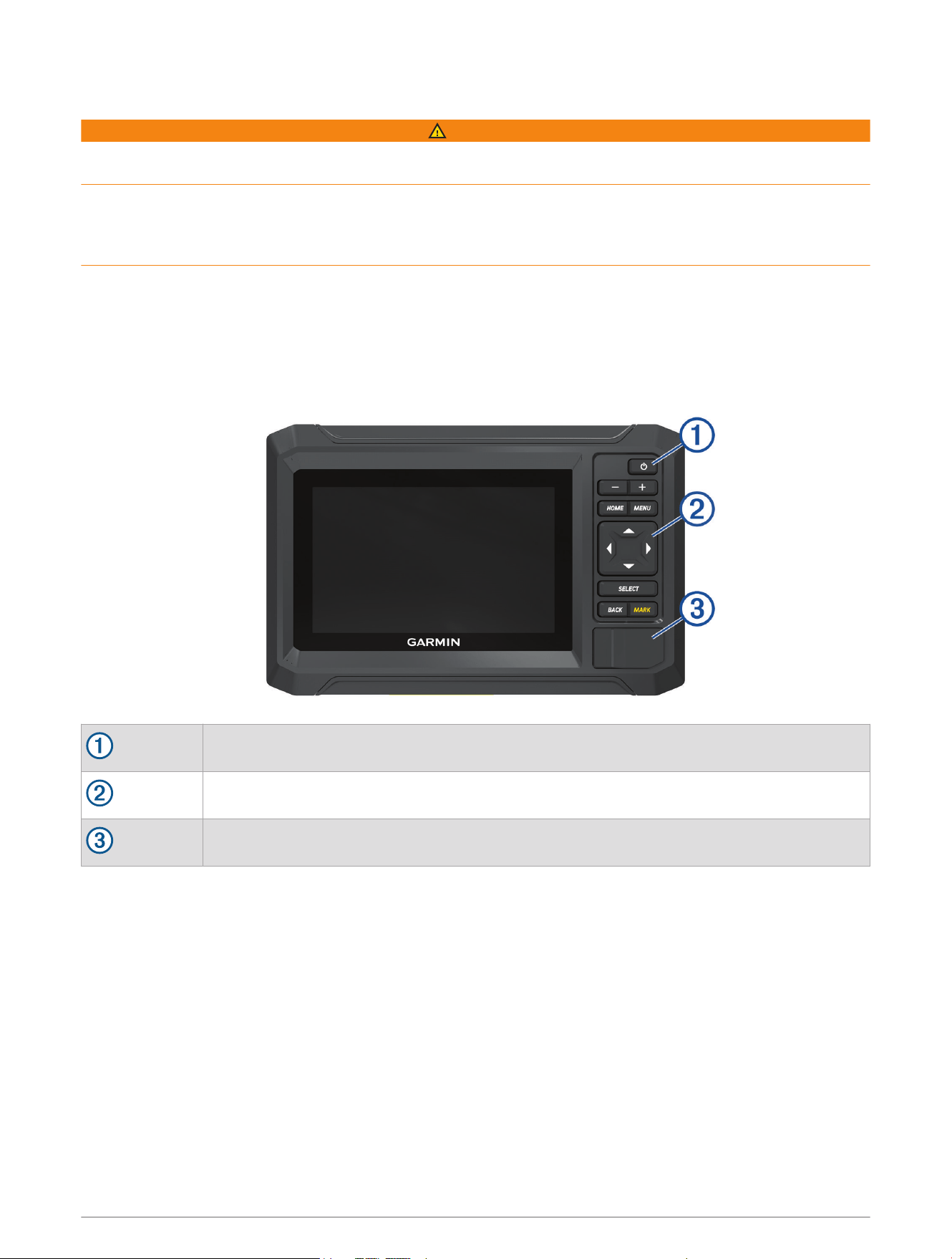
Front View
Power key
Device keys
microSD
®
memory card slot
Introduction 1
Device Keys
Turns on and off the device when held.
Opens a shortcut menu when quickly pressed and released.
Scrolls through the brightness levels when pressed repeatedly.
Zooms out.
Zooms in.
HOME
Opens the Home screen.
Takes a screenshot when held
1
MENU Opens a menu of options for the page, when applicable.
Scrolls, highlights options, and moves the cursor.
SELECT Selects the highlighted option.
BACK Returns to the previous screen.
MARK
Saves the present location as a waypoint.
Marks a MOB (Man Overboard) location when held.
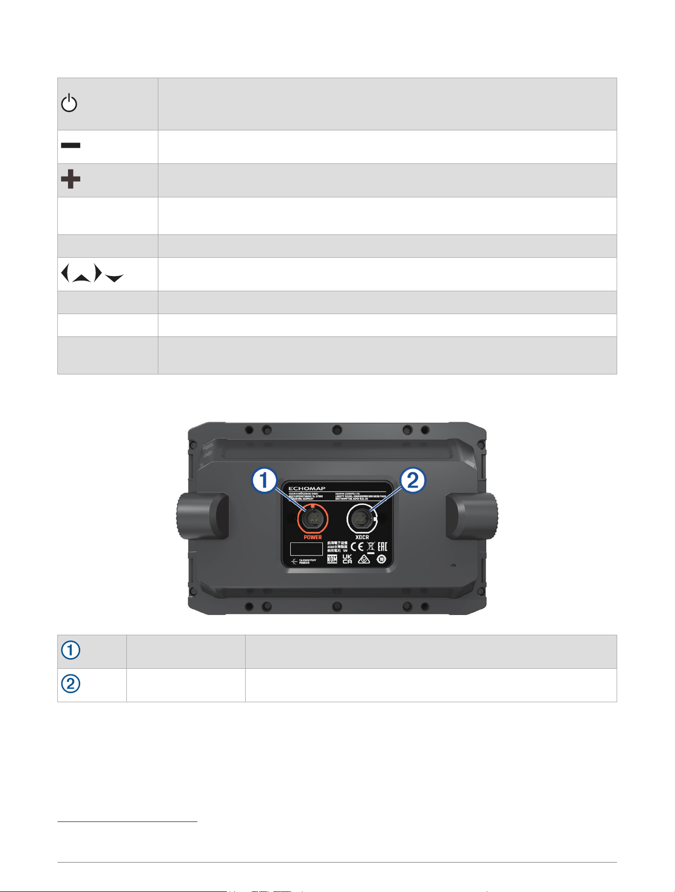
Connector View
POWER Power cable port
XDCR 4-pin transducer cable port
1
This feature requires a microSD memory card (Inserting Memory Cards, page4).
2 Introduction
Tips and Shortcuts
• Press to turn on the chartplotter.
• From any screen, press repeatedly to scroll through the brightness levels, if available. This can be helpful
when the brightness is so low you cannot see the screen.
• Select HOME from any screen to open to the home screen.
• Select MENU to open additional settings about that screen.
• Select BACK when finished with a menu, if necessary.
• Press to open additional options, such as adjusting the backlight.
• Press , and select Power > Turn Off System, or hold until the Turn Off System bar fills to turn off the
chartplotter, when available.
• Press , and select Power > Sleep Station to set the chartplotter to standby mode, when available.
To exit standby mode, select .
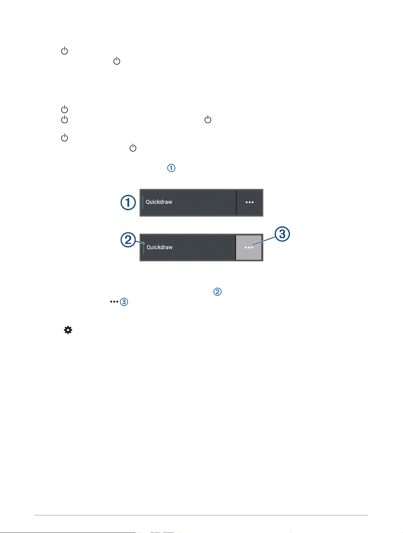
• If arrows indicate not all options are visible, press the indicated arrow key to view the additional options.
• On some menu buttons, select the button to enable the option.
A green light on an option indicates the option is enabled .
• When available, select to open the menu.
Accessing Owner's Manuals on the Chartplotter
1 Select > Owner's Manual.
2 Select a manual.
3 Select Open.
Accessing the Manuals from the Web
You can get the latest owner's manual and translations of manuals from the Garmin website.
1 Go to garmin.com/manuals/echomapUHD2.
2 Select the Owner's Manual.
A web manual opens. You can download the entire manual by selecting Download PDF.
Garmin Support Center
Go to support.garmin.com for help and information, such as product manuals, frequently asked questions,
videos, software updates, and customer support.
Introduction 3
Inserting Memory Cards
As of software version 34.00, this device supports up to a 1TB microSD memory card, formatted to exFAT with
speed class 10 or higher.
NOTE: When you insert a new memory card into the chartplotter, the chartplotter starts writing private
information onto the newly-added card.
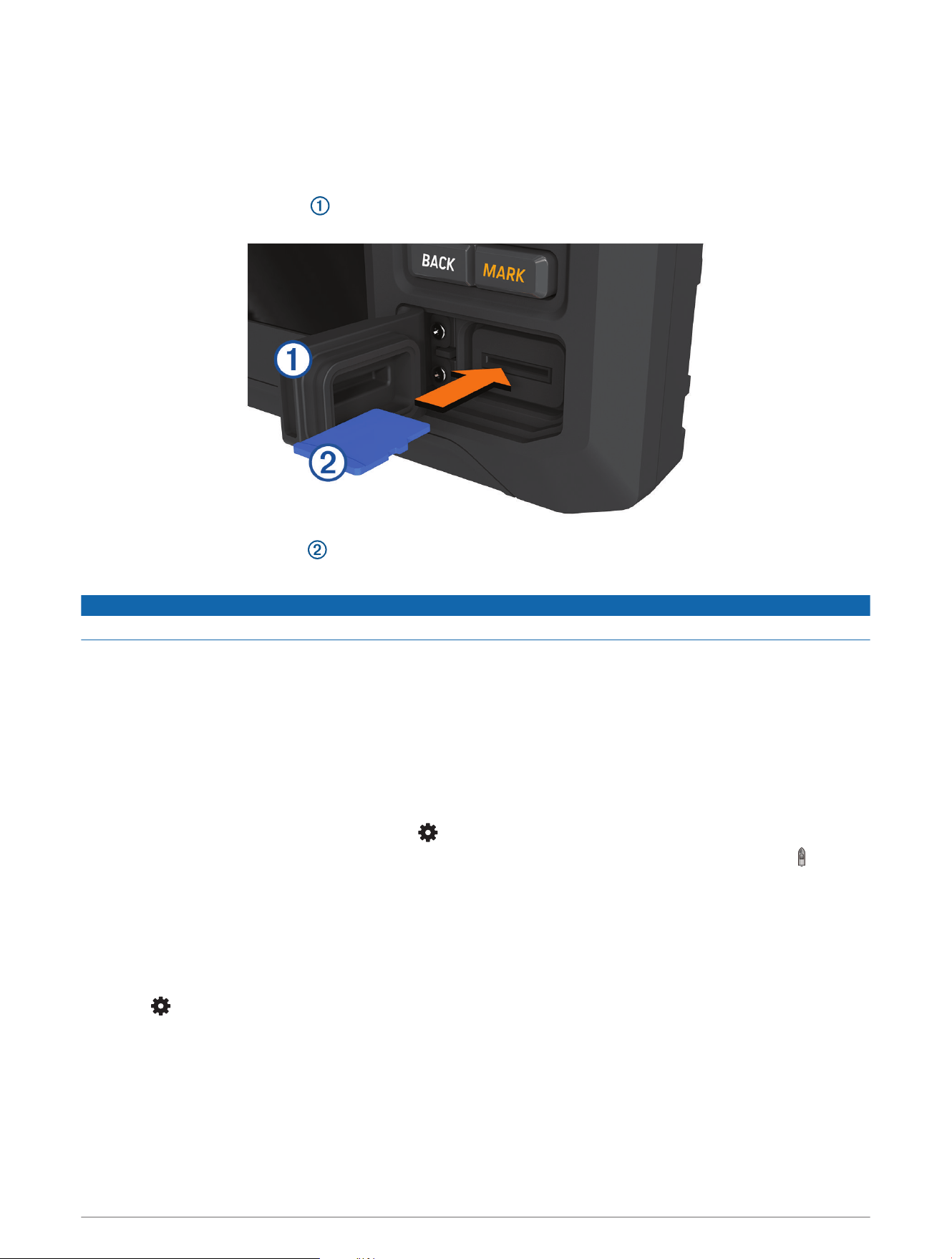
1 Open the access flap or door on the front of the chartplotter.
2 Fully insert the memory card .
3 Clean and dry the gasket and door.
NOTICE
To prevent corrosion, be sure the memory card, gasket, and door are thoroughly dry before closing the door.
4 Close the door.
Acquiring GPS Satellite Signals
The device may need a clear view of the sky to acquire satellite signals. The time and date are set automatically
based on the GPS position.
1 Turn on the device.
2 Wait while the device locates satellites.
It may take 30 to 60 seconds to acquire satellite signals.
To view the GPS satellite signal strength, select > System > Satellite Positioning.
If the device loses satellite signals, a flashing question mark appears over the boat position indicator ( ) on the
chart.
For more information about GPS, go to garmin.com/aboutGPS. For help acquiring satellite signals, see My
device will not acquire GPS signals, page69.
Selecting the GPS Source
You can select your preferred source for GPS data, if you have more than one GPS source.
1 Select > System > Satellite Positioning > Source.
2 Select the source for GPS data.
4 Introduction
Customizing the Chartplotter
Home Screen
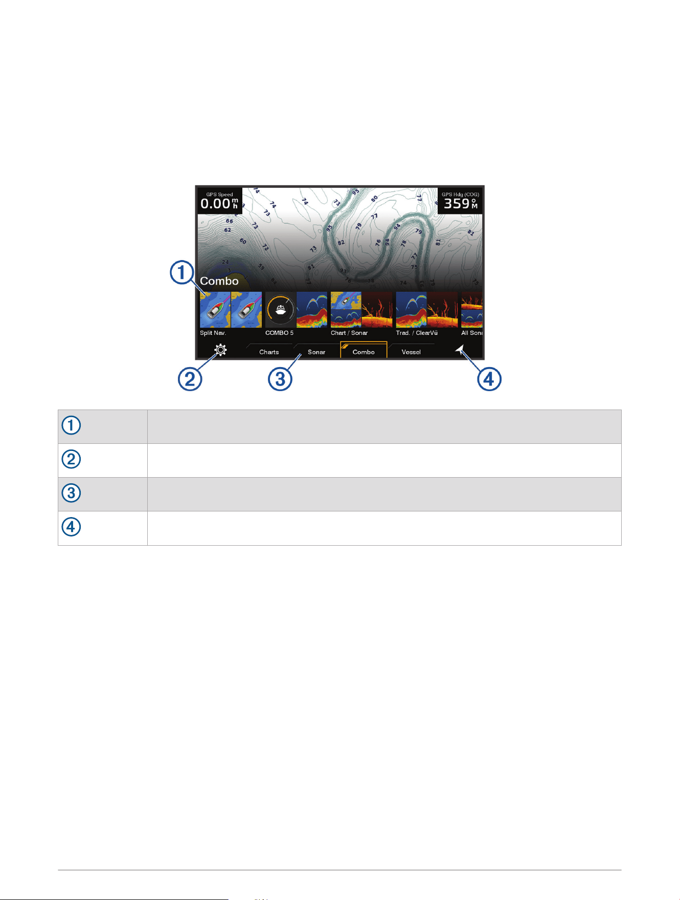
The home screen is an overlay that provides access to all of the features in the chartplotter. The features are
dependent on the accessories you have connected to the chartplotter. You may not have all of the options and
features discussed in this manual.
When viewing any screen, you can return to the home screen by selecting HOME.
Features buttons
Settings menu button
Category tabs
Opens the Where To menu
The categories tabs provide quick access to the main features of your chartplotter. For example, the Sonar tab
displays the views and screens related to the sonar feature.
TIP: To view the available categories tabs, you may need to use the arrow keys to scroll.
Rearranging the Category Items
You can customize the screen by rearranging the items in the categories.
1 Select a category to customize, such as Charts
2 Highlight a feature button, such as Nav. Chart.
3 Press and hold the SELECT button.
4 Select Rearrange.
Arrows appear on the feature buttons.
5 Reselect the button to move.
6 Use the arrow keys to highlight the new location and deselect.
7 Select the new location for the button.
8 Repeat until you finish customizing the screen.
9 Select BACK or Home when finished.
Customizing the Chartplotter 5
Customizing Pages
Customizing with Combination Pages
You can customize the layout and data shown in the combination pages.
1 Select Combo.
2 Select a combo page to customize.
3 Select MENU > Edit Combo.
4 Select an option:
• To change the name of a combo, select Name, and enter a new name.
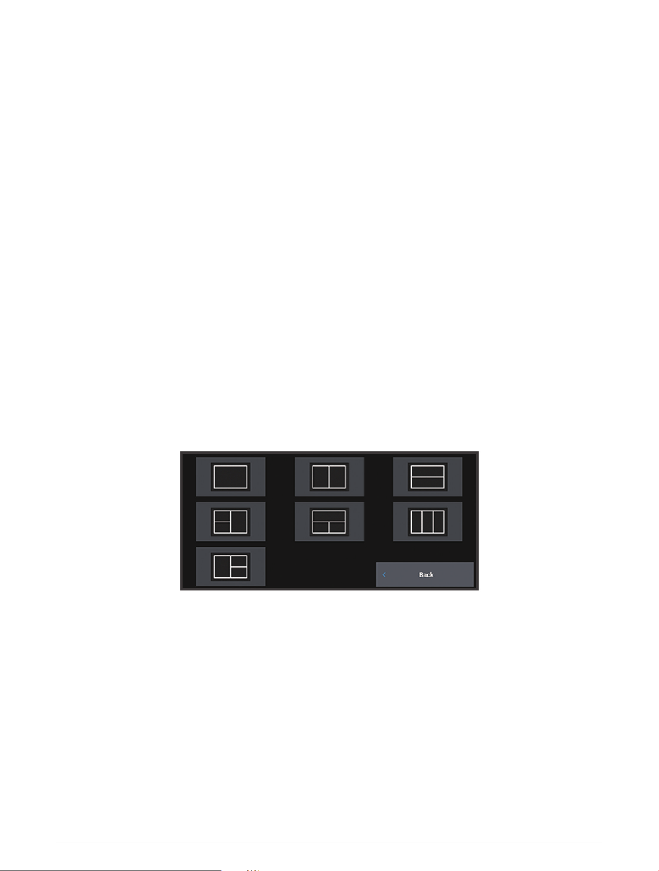
• To change the layout and number of functions shown, select Layout, and select an option.
• To change the function of a portion of the screen, use the arrow keys to highlight the window to change,
select it, and select a function.
• To change how the screens are split, select a combo page, select Resize Layout and use the arrow keys to
adjust the size.
• To change the data shown on the page and additional data bars, select Overlays, and select an option.
5 Select Done.
Creating a New Combination Page
You can create a custom combination page to suit your needs.
1 Select Combo > Add Combo.
2 Select a window.
3 Select a function for the window.
4 Repeat these steps for each window of the page.
5 Select Layout, and select a layout.
6 Select Name, enter a name for the page, and select Done.
7 Select Overlays, and select which data to show.
8 Select Done when you have finished customizing the page.
Deleting a Combination Page
1 Select Combo.
2 Highlight a combination page to delete.
3 Select MENU.
4 Select Delete Combo > Yes.
6 Customizing the Chartplotter
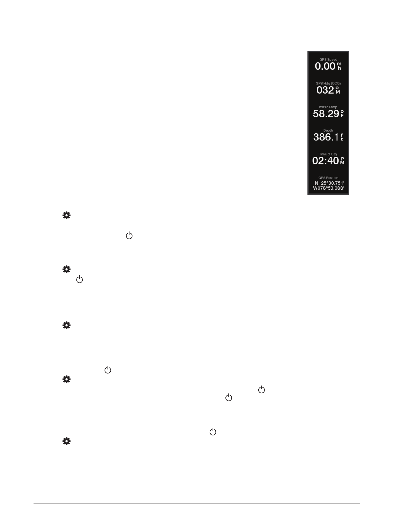
Customizing the Data Overlays
You can customize the data in the data overlays shown on a screen.
1 Select an option based on the type of screen you are viewing:
• From a full screen view, select MENU > Edit Overlays.
• From a combination screen, select MENU > Edit Combo > Overlays.
2 Select an item to customize the data and data bar:
• To show the data overlays, select Data, select the location, and select BACK.
• To change the data shown in an overlay box, select the overlay box, select the new
data to show, and select BACK.
• To customize the information shown when navigating, select Navigation, and select
an option.
• To turn on other data bars, select Top Bar, Bottom Bar, Left Bar, or Right Bar, and
select the necessary options.
3 Select Done.
Adjusting the Backlight
1 Select > System > Sounds and Display > Backlight.
2 Adjust the backlight.
TIP: From any screen, press repeatedly to scroll through the brightness levels. This can be helpful when
the brightness is so low you cannot see the screen.
Adjusting the Color Mode
1 Select > System > Sounds and Display > Color Mode.
TIP: Select > Color Mode from any screen to access the color settings.
2 Select an option.
Adjusting the Color Theme
You can change the highlight and accent color used on most chartplotter screens.
1 Select > System > Sounds and Display > Color Theme.
2 Select an option.
Turning On the Chartplotter Automatically
You can set the chartplotter to turn on automatically when the power is applied. Otherwise, you must turn on the
chartplotter by pressing .
Select > System > Auto Power Up.
NOTE: When Auto Power Up is On, and the chartplotter is turned off using , and power is removed and
reapplied within less than two minutes, you may need to press to restart the chartplotter.
Automatically Turning Off the System
You can set the chartplotter and the whole system to turn off automatically after it has been asleep for the
selected length of time. Otherwise, you must press and hold to turn off the system manually.
1 Select > System > Auto Power Off.
2 Select an option.
Customizing the Chartplotter 7
Customizing the Startup Screen
You can personalize the image that is displayed when the chartplotter is turning on. For the best fit, the
image should be 50MB or less and conform to the recommended dimensions (Recommended Startup Image
Dimensions, page72).
1 Insert a memory card that contains the image you want to use.
2 Select > System > Sounds and Display > Startup Image > Select Image.
3 Select the memory card slot.
4 Select the image.
5 Select Set as Startup Image.
The new image is shown when turning on the chartplotter.
ActiveCaptain
®
App
WARNING
This feature allows users to submit information. Garmin makes no representations about the accuracy,
completeness, or timeliness of information submitted by users. Any use or reliance on the information
submitted by users is at your own risk.
The ActiveCaptain app provides a connection to your ECHOMAP UHD2 chartplotter, maps and charts, and the
ActiveCaptain community for a connected boating experience.
On your mobile device with the ActiveCaptain app, you can download, purchase, and update maps and charts.
You can use the app to easily and quickly transfer user data, such as waypoints and routes, connect to the
Garmin Quickdraw
™
Contours Community, update device software, and plan your trip.
ActiveCaptain Roles
Your level of interaction with the ECHOMAP UHD2 device using the ActiveCaptain app depends on your role.
Feature Owner Guest
Register device, built-in maps, and supplemental map cards to account Yes No
Update software Yes Yes
Automatically transfer Garmin Quickdraw contours you have downloaded or created Yes No
Automatically transfer user data, such as waypoints and routes Yes No
Begin navigating to a specific waypoint or navigating a specific route, and send that waypoint
or route to the ECHOMAP UHD2 device
Yes Yes
8 ActiveCaptain
®
App
Getting Started with the ActiveCaptain App
You can connect a mobile device to the ECHOMAP UHD2 device using the ActiveCaptain app. The app provides
a quick and easy way for you to interact with your ECHOMAP UHD2 device and complete such tasks as sharing
data, registering, updating the device software.
1 From the ECHOMAP UHD2 device, select Vessel > ActiveCaptain.
2 From the ActiveCaptain page, select Wi-Fi Network > Wi-Fi > On.
3 Enter a name and password for this network.
4 Insert a memory card in the ECHOMAP UHD2 device's card slot (Inserting Memory Cards, page4).
5 Select Set ActiveCaptain Card.
NOTICE
You might be prompted to format the memory card. Formatting the card deletes all information saved on the
card. This includes any saved user data, such as waypoints. Formatting the card is recommended, but not
required. Before formatting the card, you should save the data from the memory card onto the device internal
memory (Copying User Data from a Memory Card, page62). After formatting the card for the ActiveCaptain
app, you can transfer the user data back to the card (Copying All User Data to a Memory Card, page63).
NOTE: Formatting the memory card in the chartplotter retains the format type and is not able to change it. If
you want to change a card format from FAT32 to exFAT, for example, you must make that change using a
computer or other device before using the card in the chartplotter.
Be sure the card is inserted each time you want to use the ActiveCaptain feature.
6 From the application store on your mobile device, install and open the ActiveCaptain
app.
TIP: You can scan this QR code using your mobile device to download the app.
7 Bring the mobile device within 32m (105ft.) of the ECHOMAP UHD2 device.
8 From your mobile device settings, open the Wi‑Fi
®
connections page, and connect to the
ECHOMAP UHD2 device, using the name and password you entered in step 3.
Updating Software with the ActiveCaptain App
If your device has Wi‑Fi technology, you can use the ActiveCaptain app to download and install the latest
software updates for your device.
NOTICE
Software updates may require the app to download large files. Regular data limits or charges from your Internet
service provider apply. Contact your Internet service provider for more information about data limits or charges.
The installation process can take several minutes.
1 Connect the mobile device to the ECHOMAP UHD2 device (Getting Started with the ActiveCaptain App,
page9).
2 When a software update is available and you have internet access on your mobile device, select Software
Updates > Download.
The ActiveCaptain app downloads the update to the mobile device. When you reconnect the app to the
ECHOMAP UHD2 device, the update is transferred to the device. After the transfer is complete, you are
prompted to install the update.
3 When you are prompted by the ECHOMAP UHD2 device, select an option to install the update.
• To update the software immediately, select OK.
• To delay the update, select Cancel. When you are ready to install the update, select ActiveCaptain >
Software Updates > Install Now.
NOTE: For the best experience, you should keep the software on your device up to date. Software updates
provide changes and improvements to privacy, security, and features.
ActiveCaptain
®
App 9
Updating Charts with ActiveCaptain
NOTE: Before you can update your charts, you must register them (Getting Started with the ActiveCaptain App,
page9).
You can use the ActiveCaptain app to download and transfer the latest chart updates for your device. To
shorten download time and conserve storage space, you can download only the areas of the chart you need.
After you download a chart or area for the first time, updates are automatic each time you open ActiveCaptain.
If you are downloading an entire chart, you can use the Garmin Express
™
app to download the map onto
a memory card (Updating Your Charts Using the Garmin Express App, page67). The Garmin Express app
downloads large charts more quickly than the ActiveCaptain app.
NOTICE
Chart updates may require the app to download large files. Regular data limits or charges from your internet
service provider apply. Contact your internet service provider for more information about data limits or charges.
1 When you have internet access on your mobile device, select Chart > > Download Charts.
2 Select the area to download.
3 Select Download.
4 If necessary, select the map to update.
The ActiveCaptain app downloads the update to the mobile device. When you reconnect the app to the
ECHOMAP UHD2 device, the update is transferred to that device. After the transfer is complete, the updated
charts are available for use.
Chart Subscriptions
A chart subscription allows you to access the latest chart updates and additional content using the
ActiveCaptain mobile app. You can download updated charts and content each day.
You can purchase, activate, and renew chart subscriptions using the ActiveCaptain mobile app (Detailed Charts,
page12).
Wireless Sharing
You can connect an ECHOMAP UHD2 5/7 cv device to another ECHOMAP UHD2 device or to a ECHOMAP
Ultra2 device wirelessly to share user data and sonar (Connecting Two Compatible ECHOMAP Devices to Share
User Data and Sonar, page11). The first time you open the wireless network settings, you are prompted to set
up the wireless network on the host device. After you set up the network, you can also connect the device to
other wireless devices, such as your phone, to use the ActiveCaptain app (Getting Started with the ActiveCaptain
App, page9).
Setting Up the Wi‑Fi Network
This device can host a Wi‑Fi network to which you can connect wireless devices such as another chartplotter or
your phone. The first time you access the wireless network settings, you are prompted to set up the network.
1 Select > Communications > Wi-Fi Network > Wi-Fi > On > OK.
2 If necessary, enter a name for this wireless network.
3 Enter a password.
You will need this password to access the wireless network from a wireless device, such as your phone. The
password is case-sensitive.
10 Wireless Sharing
Connecting Two Compatible ECHOMAP Devices to Share User Data and Sonar
You can connect an ECHOMAP UHD2 5/7 cv device to another ECHOMAP UHD2 device or to a ECHOMAP
Ultra2 device to share user data and sonar wirelessly.
User data is shared automatically between the two devices while they are connected. Sonar sharing may require
you to select a sonar source (Sonar Sharing, page11).
To connect the two devices, you must designate one device as the host and the other device as the client.
You can only connect two compatible ECHOMAP devices at a time. The host device can be connected to other
wireless devices like your phone or tablet while it is connected with the client device.
NOTE: An ECHOMAP UHD2 6/7/9 sv or ECHOMAP Ultra 2 device cannot connect to an ECHOMAP UHD2 5/7 cv
set as the host device. You must set up the ECHOMAP UHD2 6/7/9 sv or ECHOMAP Ultra 2 device as the host in
this situation.
1 Ensure the two compatible ECHOMAP devices are within range, 32m (105ft.), and turn on both devices.
2 On the compatible ECHOMAP device that will host the network, set up the Wi‑Fi network (Setting Up the Wi‑Fi
Network, page10).
3 On the compatible ECHOMAP host device, select > Communications > Wi-Fi Network > Wi-Fi > On > Host
> Pair Chartplotter > Start.
4 On the compatible ECHOMAP client device, select > Communications > Wi-Fi Network > Wi-Fi > On >
Client > Pair Host > Start.
5 Select OK after devices connect successfully.
To unpair the devices and remove the wireless credentials so they do not attempt to connect in the future, on
the client device select > Communications > Wi-Fi Network > Unpair.
If you cannot connect the two devices, troubleshoot the connection and try again (Troubleshooting the Wireless
Connection, page11).
Sonar Sharing
Two compatible ECHOMAP devices connected over the Wi‑Fi network can share sonar (Connecting Two
Compatible ECHOMAP Devices to Share User Data and Sonar, page11).
If both of the ECHOMAP devices have a transducer connected, each device uses its own sonar source
automatically. You can switch the sonar source manually to the other device (Selecting a Sonar Source,
page43).
If only one ECHOMAP device has a transducer connected, that device is the sonar source for both devices.
Troubleshooting the Wireless Connection
If you cannot connect two compatible ECHOMAP devices wirelessly, check the following items and try again.
• If you are connecting an ECHOMAP UHD2 6/7/9 sv or ECHOMAP Ultra 2 device and a ECHOMAP UHD2
5/7 cv device, you must set up the ECHOMAP UHD2 6/7/9 sv or ECHOMAP Ultra 2 as the network host. A
ECHOMAP UHD2 6/7/9 sv or ECHOMAP Ultra 2 device cannot connect to a ECHOMAP UHD2 5/7 cv device
set up as the host.
• Ensure the two devices are within range (32m (105ft.)).
• Check for signal obstructions between the devices, especially metal.
• Turn the devices off and on again, and try to connect again.
Connecting a Wireless Device to the Chartplotter
Before you can connect a wireless device to the chartplotter wireless network, you must configure the
chartplotter wireless network (Setting Up the Wi‑Fi Network, page10).
You can connect multiple wireless devices to the chartplotter to share data.
1 From the wireless device, turn on the Wi‑Fi technology and search for wireless networks.
2 Select the name of your chartplotter wireless network (Setting Up the Wi‑Fi Network, page10).
3 Enter the chartplotter password.
Wireless Sharing 11

Managing the Wi‑Fi Network
Changing the Wi‑Fi Host
If there are multiple chartplotters with Wi‑Fi technology on the Garmin marine network, you can change which
chartplotter is the Wi‑Fi host. This can be helpful if you are having trouble with Wi‑Fi communications. Changing
the Wi‑Fi host allows you to select a chartplotter that is physically closer to your mobile device.
1 Select > Communications > Wi-Fi Network > Advanced > Wi-Fi Host.
2 Follow the on-screen instructions.
Changing the Wireless Channel
You can change the wireless channel if you have trouble finding or connecting to a device, or if you experience
interference.
1 Select > Communications > Wi-Fi Network > Advanced > Channel.
2 Enter a new channel.
You do not need to change the wireless channel of devices connected to this network.
Charts and 3D Chart Views
The charts and 3D chart views that are available depend on the map data and accessories used.
NOTE: 3D chart views are available with premium charts, in some areas.
You can access the charts and 3D chart views by selecting Charts.
Nav. Chart: Shows navigation data available on your pre-loaded maps and from supplemental maps, if available.
The data includes buoys, lights, cables, depth soundings, marinas, and tide stations in an overhead view.
Fishing Chart: Provides a detailed view of the bottom contours and depth soundings on the chart. This
chart removes navigational data from the chart, provides detailed bathymetric data, and enhances bottom
contours for depth recognition. This chart is best for offshore deep-sea fishing.
NOTE: The Fishing chart is available with premium charts, in some areas.
Perspective 3D: Provides a view from above and behind the boat (according to your course) and provides a
visual navigation aid. This view is helpful when navigating tricky shoals, reefs, bridges, or channels, and is
beneficial when trying to identify entry and exit routes in unfamiliar harbors or anchorages.
3D Chart: Shows a detailed, three-dimensional view from above and behind the boat (according to your course)
and provides a visual navigation aid. This view is helpful when navigating tricky shoals, reefs, bridges, or
channels, and when trying to identify entry and exit routes in unfamiliar harbors or anchorages.
Fish Eye 3D: Provides an underwater view that visually represents the sea floor according to the chart
information. When a sonar transducer is connected, suspended targets (such as fish) are indicated by red,
green, and yellow spheres. Red indicates the largest targets and green indicates the smallest.
Relief Shading: Provides high resolution elevation shading of lakes and coastal waters. This chart can be
helpful for fishing and diving.
NOTE: The Relief Shading chart is available with premium charts, in some areas.
Detailed Charts
This chartplotter is compatible with the latest Garmin Navionics+
™
cartography and additional premium chart
features. You can obtain these charts in three ways:
• You can purchase a chartplotter with preloaded detailed charts.
• You can purchase chart regions on a memory card from your Garmin dealer or from garmin.com.
• You can purchase chart regions in the ActiveCaptain app, and download them to your chartplotter.
NOTE: You must activate preloaded charts and charts purchased on a memory card using the ActiveCaptain
app before you can access the full chart features on your chartplotter.
12 Charts and 3D Chart Views
Activating a Marine Chart Subscription
Before you can use the full features of Garmin Navionics+ charts that are preloaded on your device or
purchased on a memory card, you must activate your subscription using the ActiveCaptain app.
Your subscription allows you to access the latest chart updates and additional content included with your
purchase.
1 If you purchased charts on a memory card, insert the card into a memory card slot on the chartplotter or
Garmin memory card reader.
2 Open the ActiveCaptain app on your mobile device, and connect it to the chartplotter (Getting Started with the
ActiveCaptain App, page9).
3 After the ActiveCaptain app connects to the chartplotter, make sure your mobile device is connected to the
internet.
4 In the ActiveCaptain app, select Chart > > My Charts, and verify that an active subscription for the charts
is shown in the list.
5 If necessary, connect the ActiveCaptain app to the chartplotter to complete the activation process.
The ActiveCaptain app activates the subscription automatically after it connects to the internet and then to
the chartplotter. The ActiveCaptain app shows the subscription status in the My Charts list.
NOTE: It might take a few hours to verify the new subscription.
Purchasing a Chart Subscription with ActiveCaptain
1 Connect your mobile device to the internet and open the ActiveCaptain app.
2 Select Chart > > My Charts > Add a Chart Subscription.
3 Select a chart.
4 Select Subscribe Now.
NOTE: It might take a few hours to display the new subscription.
Renewing Your Subscription
Your cartography subscription expires after one year. After the subscription expires, you can continue using the
downloaded charts, but you are not able to download the latest chart updates or additional content.
1 Connect your mobile device to the internet and open the ActiveCaptain app.
2 Select Chart > > My Charts.
3 Select the chart to renew.
4 Select Renew Now.
NOTE: It might take a few hours to display the renewed subscription.
Charts and 3D Chart Views 13
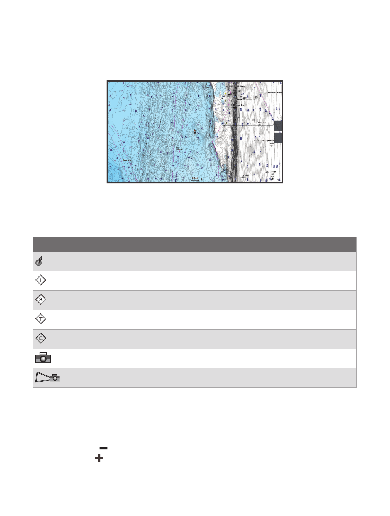
Navigation Chart and Fishing Chart
NOTE: The Fishing chart is available with premium charts, in some areas.
The Nav. Chart is optimized for navigation. You can plan a course, view map information, and use the chart as a
navigational aid. To open the Nav. Chart, select Charts > Nav. Chart.
The Fishing Chart provides a detailed view with more bottom detail and fishing content. This chart is optimized
for use when fishing. To open the
Fishing Chart, select Charts > Fishing Chart.
Chart Symbols
This table contains some of the common symbols you might see on the detailed charts.
Icon Description
Buoy
Information
Marine services
Tide station
Current station
Overhead photo available
Perspective photo available
Other features common to most charts include depth contour lines, intertidal zones, spot soundings (as
depicted on the original paper chart), navigational aids and symbols, obstructions, and cable areas.
Zooming In and Out of the Chart
The zoom level is indicated by the scale number at the bottom of the chart. The bar under the scale number
represents that distance on the chart.
• To zoom out, select .
• To zoom in, select .
14 Charts and 3D Chart Views

Panning the Chart with the Keys
You can move the chart to view an area other than your present location.
1 From the chart, use the arrow keys.
2 Select BACK to stop panning and return the screen to your present location.
NOTE: To pan from a combination screen, select SELECT.
Selecting an Item on the Map Using the Device Keys
1 From a chart or 3D chart view, select , , , or to move the cursor.
2 Select SELECT.
Measuring a Distance on the Chart
1 From a chart, select a location.
2 Select Measure.
A push pin appears on the screen at your present location. The distance and angle from the pin is listed in
the corner.
TIP: To reset the pin and measure from the current location of the cursor, select Set Reference.
Creating a Waypoint on the Chart
1 From a chart, select a location or object.
2 Select Create Waypoint.
Viewing Location and Object Information on a Chart
You can view information, such as tide, current, celestial, chart notes, or local services, about a location or an
object on the Navigation chart or the Fishing chart.
1 From the Navigation chart or Fishing chart, select a location or object.
A list of options appears. The options that appear vary based on the location or object you selected.
2 Select Information.
Viewing Details about Navaids
From the Navigation chart, Fishing chart, Perspective 3D chart view, or Mariner’s Eye 3D chart view, you can
view details about various types of navigation aids, including beacons, lights, and obstructions.
NOTE: The Fishing chart is available with premium charts, in some areas.
NOTE: 3D chart views are available with premium charts, in some areas.
1 From a chart or 3D chart view, select a navaid.
2 Select the name of the navaid.
Charts and 3D Chart Views 15
Navigating to a Point on the Chart
WARNING
All route and navigation lines displayed on the chartplotter are only intended to provide general route guidance
or to identify proper channels, and are not intended to be precisely followed. Always defer to the navaids and
conditions on the water when navigating to avoid groundings or hazards that could result in vessel damage,
personal injury, or death.
The Auto Guidance feature is based on electronic chart information. That data does not ensure obstacle and
bottom clearance. Carefully compare the course to all visual sightings, and avoid any land, shallow water, or
other obstacles that may be in your path.
When using Go To, a direct course and a corrected course may pass over land or shallow water. Use visual
sightings, and steer to avoid land, shallow water, and other dangerous objects.
NOTE: The Fishing chart is available with premium charts, in some areas.
NOTE: Auto Guidance is available with premium charts, in some areas.
1 From the Navigation chart or Fishing chart, select a location.
2 If necessary, select Navigate To.
3 Select an option:
• To navigate directly to the location, select Go To or .
• To create a route to the location, including turns, select Route To or .
• To use Auto Guidance, select Auto Guidance or .
4 Review the course indicated by the magenta line (Route Color Coding, page27).
NOTE: When using Auto Guidance, a gray segment within any part of the magenta line indicates that Auto
Guidance cannot calculate part of the Auto Guidance line. This is due to the settings for minimum safe water
depth and minimum safe obstacle height.
5 Follow the magenta line, steering to avoid land, shallow water, and other obstacles.
16 Charts and 3D Chart Views

Premium Chart Features
WARNING
All route and navigation lines displayed on the chartplotter are only intended to provide general route guidance
or to identify proper channels, and are not intended to be precisely followed. Always defer to the navaids and
conditions on the water when navigating to avoid groundings or hazards that could result in vessel damage,
personal injury, or death.
The Auto Guidance feature is based on electronic chart information. That data does not ensure obstacle and
bottom clearance. Carefully compare the course to all visual sightings, and avoid any land, shallow water, or
other obstacles that may be in your path.
NOTE: Not all models support all charts.
Optional premium charts, such as Garmin Navionics Vision+
™
, allow you to get the most out of your chartplotter.
In addition to detailed marine charting, premium charts may contain these features, which are available in some
areas.
NOTE: Not all premium chart features are available immediately after purchase. Before you can access all
premium features you must activate your chart subscription and choose to download specific features using
the ActiveCaptain app (Activating a Marine Chart Subscription, page13).
Mariner’s Eye 3D: Provides a view from above and behind the boat for a three-dimensional navigation aid.
Fish Eye 3D: Provides an underwater, three-dimensional view that visually represents the sea floor according to
the information on the chart.
Fishing Charts: Shows the chart with enhanced bottom contours and without navigational data. This chart
works well for offshore deep-sea fishing.
High Resolution Satellite Imagery: Provides high-resolution satellite images for a realistic view of the land and
water on the Navigation chart (Showing Satellite Imagery on the Navigation Chart, page19).
Aerial Photos: Shows marinas and other navigationally significant aerial photos to help you visualize your
surroundings (Viewing Aerial Photos of Landmarks, page20).
Detailed Roads and POI data: Shows detailed road and point of interest (POI) data, which includes highly
detailed coastal roads and POIs such as restaurants, lodging, and local attractions.
Auto Guidance: Uses specified information about your vessel and chart data to determine the best path to your
destination.
Sonar Imagery: Shows sonar imagery to help show the density of the bottom.
Relief Shading: Shows the gradient of the bottom with shading.
Charts and 3D Chart Views 17
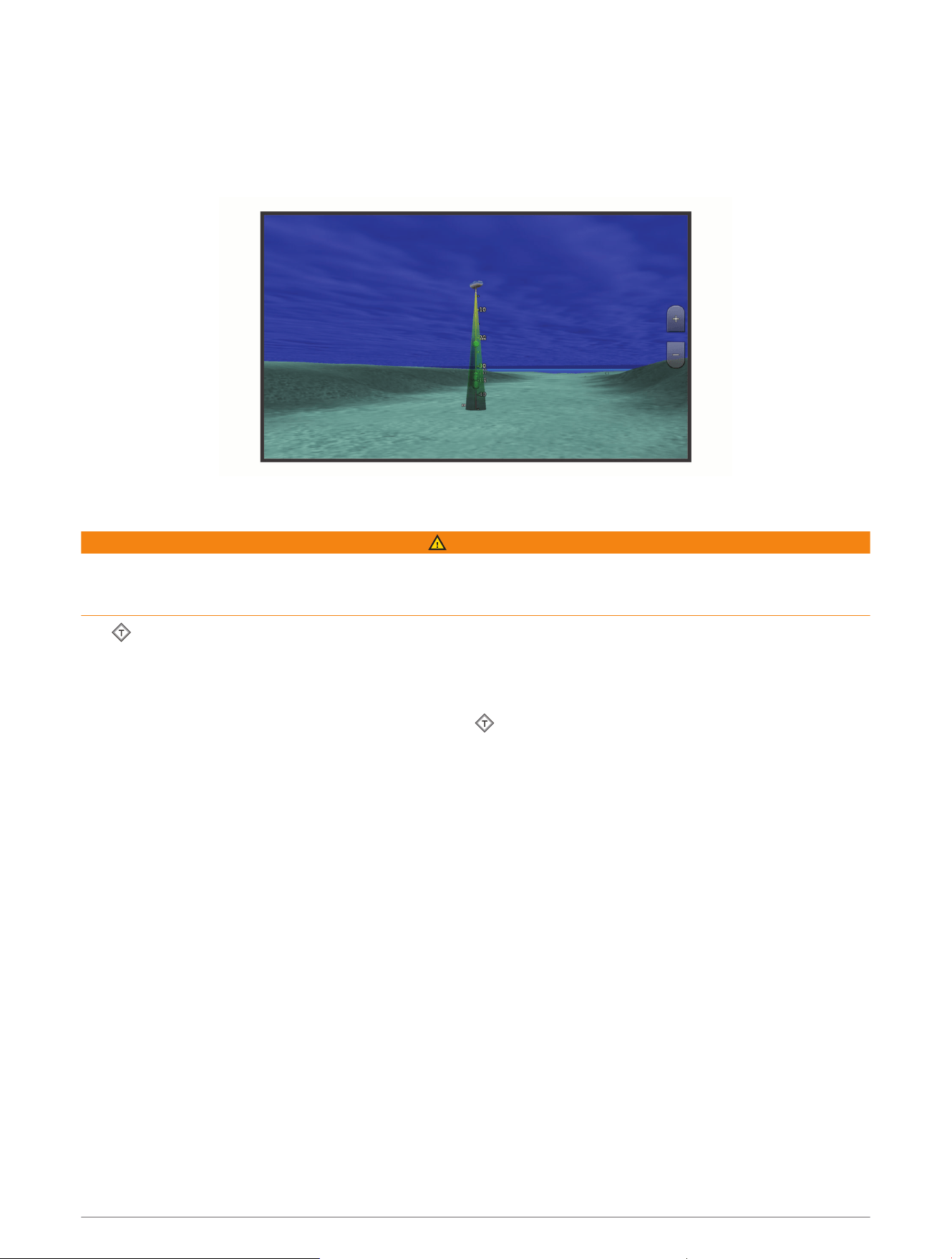
Fish Eye 3D Chart View
Using the depth contour lines of the premium charts, such as Garmin Navionics Vision+, the Fish Eye 3D chart
view provides an underwater view of the sea floor or lake bottom.
Suspended targets, such as fish, are indicated by red, green, and yellow spheres. Red indicates the largest
targets and green indicates the smallest.
Viewing Tide Station Information
WARNING
Tide and current information is for information purposes only. It is your responsibility to heed all posted
water-related guidance, to remain aware of your surroundings, and to use safe judgment in, on, and around the
water at all times. Failure to heed this warning could result in property damage, serious personal injury, or death.
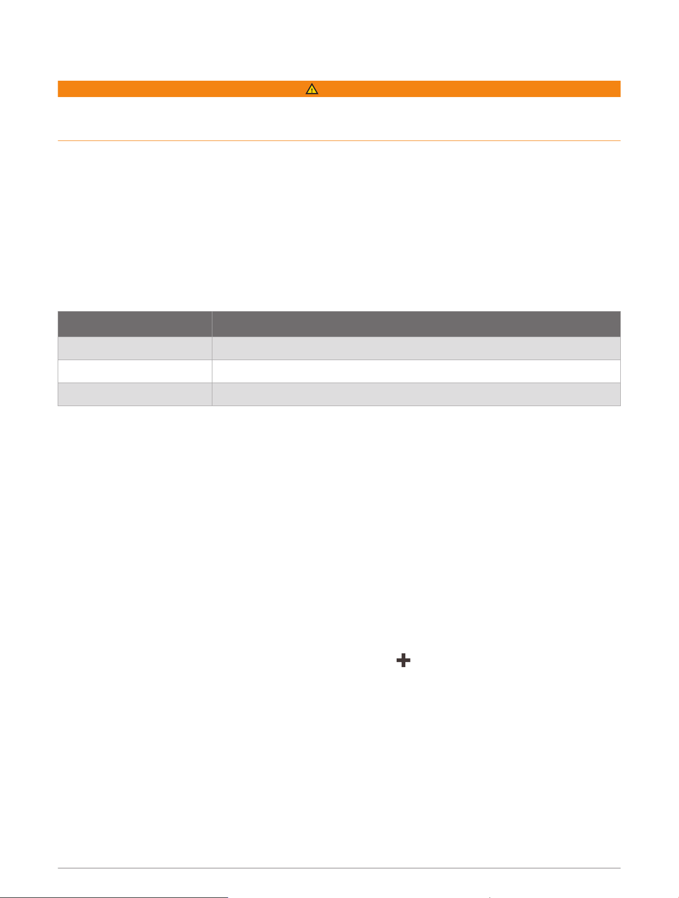
The icon on the chart indicates a tide station. You can view a detailed graph for a tide station to help predict
the tide level at different times or on different days.
NOTE: This feature is available with premium charts, in some areas.
1 From the Navigation chart or Fishing chart, select a tide station.
Tide direction and tide level information appear near .
2 Select the station name.
18 Charts and 3D Chart Views
Animated Tide and Current Indicators
WARNING
Tide and current information is for information purposes only. It is your responsibility to heed all posted
water-related guidance, to remain aware of your surroundings, and to use safe judgment in, on, and around the
water at all times. Failure to heed this warning could result in property damage, serious personal injury, or death.
NOTE: This feature is available with premium charts, in some areas.
You can view indicators for animated tide station and current direction on the Navigation chart or the Fishing
chart. You must also enable animated icons in the chart settings (Showing Tides and Current Indicators,
page19).
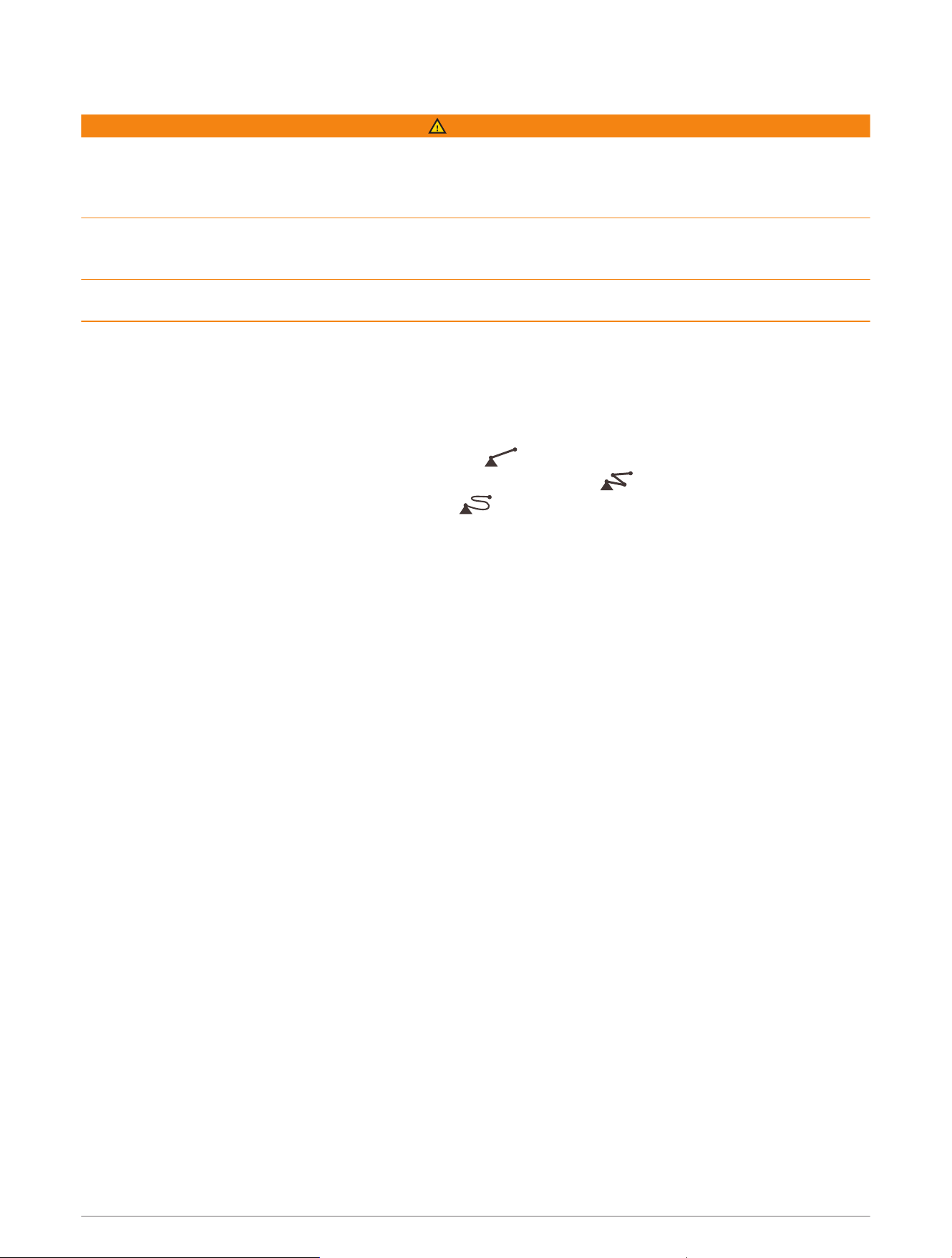
An indicator for a tide station appears on the chart as a vertical bar graph with an arrow. A red arrow pointing
downward indicates a falling tide, and a blue arrow pointing upward indicates a rising tide. When you move the
cursor over the tide station indicator, the height of the tide at the station appears above the station indicator.
Current direction indicators appear as arrows on the chart. The direction of each arrow indicates the direction
of the current at a specific location on the chart. The color of the current arrow indicates the range of speed for
the current at that location. When you move the cursor over the current direction indicator, the specific current
speed at the location appears above the direction indicator.
Color Current Speed Range
Yellow 0 to 1 knot
Orange 1 to 2 knots
Red 2 or more knots
Showing Tides and Current Indicators
NOTE: This feature is available with premium charts, in some areas.
You can show static or animated tide and current station indicators on the Navigation chart or Fishing chart.
1 From the Navigation or Fishing chart, select MENU > Layers > Chart > Tides & Currents.
2 Select an option:
• To show animated tide station indicators and animated current direction indicators on the chart, select
Animated.
• To enables the tides and current slider, which sets the time for which tides and currents are reported on
the map, select Slider.
Showing Satellite Imagery on the Navigation Chart
NOTE: This feature is available with premium charts, in some areas.
You can overlay high-resolution satellite images on the land or on both land and sea portions of the Navigation
chart.
NOTE: When enabled, high-resolution satellite images are present only at lower zoom levels. If you cannot see
high-resolution images in your optional chart region, you can select to zoom in. You also can set the detail
level higher by changing the map zoom detail.
1 From the Navigation chart, select MENU > Layers > Chart > Satellite Photos.
2 Select an option:
• Select Land Only to show standard chart information on the water, with photos overlaying the land.
NOTE: This setting must be enabled to view Standard Mapping
®
charts.
• Select Photo Map to show photos on both the water and the land at a specified opacity. Use the slider bar
to adjust the photo opacity. The higher you set the percentage, the more the satellite photos cover both
land and water.
Charts and 3D Chart Views 19

Viewing Aerial Photos of Landmarks
Before you can view aerial photos on the Navigation chart, you must turn on the Photo Points setting in the
chart setup (Chart Layers, page20).
NOTE: This feature is available with premium charts, in some areas.
You can use aerial photographs of landmarks, marinas, and harbors to help orient yourself to your surroundings
or to acquaint yourself with a marina or a harbor prior to arrival.
1 From the Navigation chart, select a camera icon:
• To view an overhead photo, select .
• To view a perspective photo, select . The photo was taken from the location of the camera, pointed
in the direction of the cone.
2 Select Photo.
Chart Menu
NOTE: Not all settings apply to all charts. Some options require premium maps or connected accessories, such
as radar.
NOTE: The menus may contain some settings that are not supported by your installed charts or your present
location. If you make changes to those settings, the changes will not impact the chart view.
From a chart, select MENU.
Layers: Adjusts the appearance of the different items on the charts (Chart Layers, page20).
Quickdraw Contours: Turns on bottom contour drawing, and allows you to create fishing map labels (Garmin
Quickdraw Contours Mapping, page24).
Settings: Adjusts the chart settings (Chart Settings, page23).
Edit Overlays: Adjusts the data shown on the screen (Customizing the Data Overlays, page7).
Chart Layers
You can turn on and off chart layers and customize features of the charts. Each setting is specific to the chart
or chart view being used.
NOTE: Not all settings apply to all charts and chartplotter models. Some options require premium maps or
connected accessories.
NOTE: The menus may contain some settings that are not supported by your installed charts or your present
location. If you make changes to those settings, the changes will not impact the chart view.
From a chart, select MENU > Layers.
Chart: Shows and hides chart-related items (Chart Layer Settings, page21).
My Vessel: Shows and hides items relating to the boat (My Vessel Layer Settings, page21).
Manage User Data: Shows and hides user data, such as waypoints, boundaries, and tracks, and opens user data
lists (User Data Layer Settings, page21).
Water: Shows and hides depth items (Water Layer Settings, page22).
Quickdraw Contours: Shows and hides Garmin Quickdraw Contours data (Garmin Quickdraw Contours Settings,
page26).
20 Charts and 3D Chart Views

Chart Layer Settings
From a chart, select MENU > Layers > Chart.
Satellite Photos: Shows high-resolution satellite images on the land or on both land and sea portions of the
Navigation chart, when certain premium maps are used (Showing Satellite Imagery on the Navigation Chart,
page19).
NOTE: This setting must be enabled to view Standard Mapping charts.
Tides & Currents: Shows current station indicators and tide station indicators on the chart (Showing Tides and
Current Indicators, page19) and enables the tides and current slider, which sets the time for which tides and
currents are reported on the map.
Land POIs: Shows points of interest on land.
Navaid: Shows navigational aids, such as ATONs and flashing lights, on the chart. Allows you to select NOAA or
IALA navaid type.
Service Points: Shows locations for marine services.
Depth: Adjusts the items on the depth layer (Depth Layer Settings, page21).
Restricted Areas: Shows information about restricted areas on the chart.
Photo Points: Shows camera icons for aerial photos (Viewing Aerial Photos of Landmarks, page20).
Depth Layer Settings
From a chart, select MENU > Layers > Chart > Depth.
Depth Shading: Specifies an upper and lower depth to shade between.
Shallow Shading: Sets the shades from the shoreline to the specified depth.
Spot Depths: Turns on spot soundings and sets a dangerous depth. Spot depths that are equal to or more
shallow than the dangerous depth are indicated by red text.
Fishing Contours: Sets the zoom level for a detailed view of bottom contours and depth soundings and
simplifies map presentation for optimal use while fishing.
My Vessel Layer Settings
From a chart, select MENU > Layers > My Vessel.
Heading Line: Shows and adjusts the heading line, which is a line drawn on the map from the bow of the boat in
the direction of travelxxx.
Heading Line > Stern Line: Shows an extension from the stern of the boat in the opposite direction of travel.
Active Tracks: Shows the active track on the chart and opens the Active Track Options menu.
Compass Rose: Shows a compass rose around your boat, indicating compass direction oriented to the heading
of the boat.
Vessel Icon: Sets the icon that represents your present location on the chart.
User Data Layer Settings
You can show user data, such as waypoints, boundaries, and tracks, on the charts.
From a chart, select MENU > Layers > Manage User Data.
Waypoints: Shows waypoints on the chart and opens the list of waypoints.
Boundaries: Shows boundaries on the chart and opens the list of boundaries.
Tracks: Shows tracks on the chart.
Charts and 3D Chart Views 21
Water Layer Settings
From a chart, select MENU > Layers > Water.
NOTE: The menu may contain some settings that are not supported by your installed charts or your present
location. If you make changes to those settings, the changes will not impact the chart view.
NOTE: Not all settings apply to all charts, views, and chartplotter models. Some options require premium maps
or connected accessories.
Depth Shading: Specifies an upper and lower depth to shade between (Depth Range Shading, page22).
Shallow Shading: Sets the shades from the shoreline to the specified depth.
Spot Depths: Turns on spot soundings and sets a dangerous depth. Spot depths that are equal to or more
shallow than the dangerous depth are indicated by red text.
Fishing Contours: Sets the zoom level for a detailed view of bottom contours and depth soundings and
simplifies map presentation for optimal use while fishing.
Relief Shading: Shows the gradient of the bottom with shading. This feature is available only with some
premium maps.
Sonar Imagery: Shows sonar imagery to help show the density of the bottom. This feature is available only with
some premium maps.
Lake Level: Sets the present water level of the lake. This feature is available only with some premium maps.
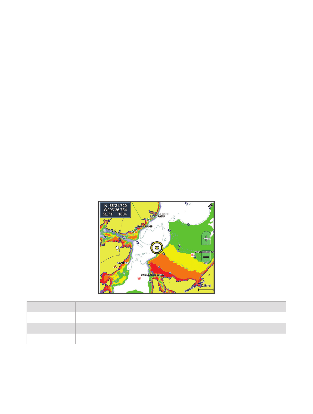
Depth Range Shading
You can set color ranges on your map to show the water depths where your target fish are currently biting. You
can set deeper ranges to monitor how quickly the bottom depth changes within a specific depth range. You can
create up to ten depth ranges. For inland fishing, a maximum of five depth ranges can help reduce map clutter.
The depth ranges apply to all charts and all bodies of water.
Some Garmin LakeVü
™
and premium supplemental charts have multiple depth range shading by default.
Red From 0 to 1.5m (from 0 to 5ft.)
Orange From 1.5 to 3m (from 5 to 10ft.)
Yellow From 3 to 4.5m (from 10 to 15ft.)
Green From 4.5 to 6.1m (from 15 to 20ft.)
To turn on and adjust, from a chart, select MENU > Layers > Water > Depth Shading.
22 Charts and 3D Chart Views
Chart Settings
NOTE: Not all settings apply to all charts and 3D chart views. Some settings require external accessories or
applicable premium charts.
From a chart, select MENU > Chart Settings.
Map Orientation: Sets the perspective of the map.
Look Ahead: Shifts your present location toward the bottom of the screen automatically as your speed
increases. Enter your top speed for the best results.
Vessel Orientation: Sets the alignment of the vessel icon on the map. The Auto option aligns the vessel icon
using GPS COG at high speeds and the magnetic heading at low speeds to better align the vessel icon with
the active track line. The Heading option aligns the vessel icon with the magnetic heading. The GPS Heading
(COG) option aligns the vessel icon using GPS COG. If the selected data source is not available, the available
data source is used instead.
WARNING
The vessel orientation setting is for informational purposes and is not intended to be precisely followed. Always
defer to the navaids and conditions on the water to avoid groundings or hazards that could result in vessel
damage, personal injury, or death.
NOTE: You can set the Map Orientation and Vessel Orientation settings separately for two navigation charts
used in a combination page.
Detail: Adjusts the amount of detail shown on the map, at different zoom levels.
Chart Size: Sets the visible size of the chart.
World Map: Uses either a basic world map or a shaded relief map on the chart. These differences are visible
only when zoomed out too far to see the detailed charts.
Inset Map: Shows a small map centered on your present location.
Fish Eye 3D Settings
NOTE: This feature is available with premium charts, in some areas.
From the Fish Eye 3D chart view, select MENU.
View: Sets the perspective of the 3D chart view.
Tracks: Shows tracks.
Sonar Cone: Shows a cone that indicates the area covered by the transducer.
Fish Symbols: Shows suspended targets.
Supported Maps
To help you have a safe and enjoyable time on the water, Garmin devices only support official maps produced
by Garmin or an approved third party producer.
You can purchase maps from Garmin. If you purchase maps from a seller other than Garmin, investigate the
seller before purchasing. Be extra cautious with online sellers. If you have purchased an unsupported map,
return it to the seller.
Charts and 3D Chart Views 23
Garmin Quickdraw Contours Mapping
WARNING
The Garmin Quickdraw Contours mapping feature allows users to generate maps. Garmin makes no
representations about the accuracy, reliability, completeness or timeliness of the maps generated by third
parties. Any use or reliance on the maps generated by third parties is at your own risk.
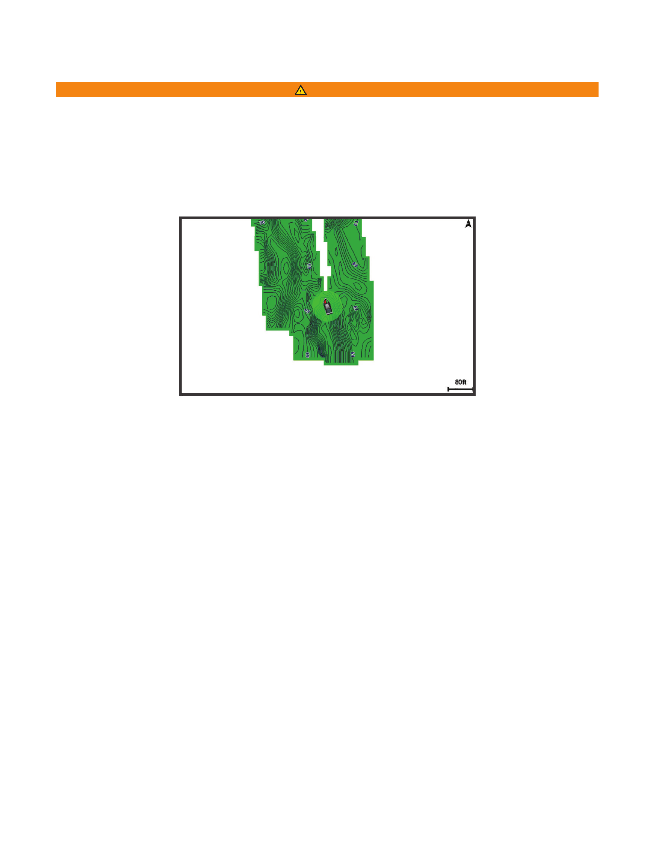
The Garmin Quickdraw Contours mapping feature allows you to instantly create maps with contours and depth
labels for any body of water.
When Garmin Quickdraw Contours records data, a colored circle surrounds the vessel icon. This circle
represents the approximate area of the map that is scanned by each pass.
A green circle indicates good depth and GPS position, and a speed under 16km/h (10mph). A yellow circle
indicates good depth and GPS position, and a speed between 16 and 32km/h (10 and 20mph). A red circle
indicates poor depth or GPS position, and a speed above 32km/h (20mph).
You can view Garmin Quickdraw Contours in a combination screen or as a single view on the map.
The amount of saved data depends on the size of your memory card, your sonar source, and the speed of your
boat as you record data. You can record longer when you use a single-beam sonar. It is estimated that you
might be able to record about 1,500hours of data onto a 2GB memory card.
When you record data on a memory card in your chartplotter, the new data is added to your existing Garmin
Quickdraw Contours map, and is saved on the memory card. When you insert a new memory card, the existing
data does not transfer onto the new card.
Mapping a Body of Water Using the Garmin Quickdraw Contours Feature
Before you can use the Garmin Quickdraw Contours feature, you must have sonar depth, your GPS position, and
a memory card with free space.
1 From a chart view, select MENU > Quickdraw Contours > Start Recording.
2 When recording is complete, select MENU > Quickdraw Contours > Stop Recording.
3 Select Manage > Name, and enter a name for the map.
Adding a Label to a Garmin Quickdraw Contours Map
You can add labels to a Garmin Quickdraw Contours map to mark hazards or points of interest.
1 From the Navigation chart, select a location.
2 Select Quickdraw Lbl..
3 Enter text for the label, and select Done.
24 Garmin Quickdraw Contours Mapping

Garmin Quickdraw Community
The Garmin Quickdraw Community is a free, public, online community that enables you to download maps
other users have created. You can share your Garmin Quickdraw Contours maps with others. You must use
the ActiveCaptain app to access the Garmin Quickdraw Community (Connecting to the Garmin Quickdraw
Community with ActiveCaptain, page25).
NOTE: The Garmin device must have a memory card slot and Wi‑Fi technology to participate in the Garmin
Quickdraw Community.
Connecting to the Garmin Quickdraw Community with ActiveCaptain
1 From your mobile device, open the ActiveCaptain app and connect to the ECHOMAP UHD2 device (Getting
Started with the ActiveCaptain App, page9).
2 From the app, select Quickdraw Community.
You can download contours from others in the community (Downloading Garmin Quickdraw Community Maps
Using ActiveCaptain, page25) and share the contours you have created (Sharing Your Garmin Quickdraw
Contours Maps with the Garmin Quickdraw Community Using ActiveCaptain, page25).
Downloading Garmin Quickdraw Community Maps Using ActiveCaptain
You can download Garmin Quickdraw Contours maps that other users have created and shared with the Garmin
Quickdraw Community.
1 From the ActiveCaptain app on your mobile device, select Quickdraw Community > Search for Contours.
2 Use the map and search features to locate an area to download.
The red dots represent Garmin Quickdraw Contours maps that have been shared for that area.
3 Select Select Download Region.
4 Drag the box to select the area to download.
5 Drag the corners to change the download area.
6 Select Download Area.
The next time you connect the ActiveCaptain app to the ECHOMAP UHD2 device, the downloaded contours are
transferred to the device automatically.
Sharing Your Garmin Quickdraw Contours Maps with the Garmin Quickdraw Community Using
ActiveCaptain
You can share Garmin Quickdraw Contours maps that you have created with others in the Garmin Quickdraw
Community.
When you share a contour map, only the contour map is shared. Your waypoints are not shared.
When you set up your ActiveCaptain app, you may have selected to share your contours with the community
automatically. If not, follow these steps to enable sharing.
From the ActiveCaptain app on your mobile device, select Sync with Plotter > Contribute to Community.
The next time you connect the ActiveCaptain app to the ECHOMAP UHD2 device, your contour maps are
transferred to the community automatically.
Garmin Quickdraw Contours Mapping 25
Garmin Quickdraw Contours Settings
From a chart, select MENU > Quickdraw Contours > Settings.
Recording Offset: Sets the distance between the sonar depth and the contour recording depth. If the water
level has changed since your last recording, adjust this setting so the recording depth is the same for both
recordings.
For example, if the last time you recorded had a sonar depth of 3.1m (10.5ft.), and today's sonar depth is
3.6m (12ft.), enter -0.5m (-1.5ft.) for the a Recording Offset value.
User Display Offset: Sets differences in contour depths and depth labels on your own contours maps to
compensate for changes in the water level of a body of water, or for depth errors in recorded maps.
Comm. Display Offset: Sets differences in contour depths and depth labels on the community contours maps to
compensate for changes in the water level of a body of water, or for depth errors in recorded maps.
Survey Coloring: Sets the color of the Garmin Quickdraw Contours display. When this setting is turned on, the
colors indicate the quality of the recording. When this setting is turned off, the contour areas use standard
map colors.
Green indicates good depth and GPS position, and a speed under 16km/h (10mph). Yellow indicates good
depth and GPS position, and a speed between 16 and 32km/h (10 and 20mph). Red indicates poor depth or
GPS position, and a speed above 32km/h (20mph).
Depth Shading: Specifies the minimum and maximum depths of a depth range and a color for that depth range.
Navigation with a Chartplotter
WARNING
All route and navigation lines displayed on the chartplotter are only intended to provide general route guidance
or to identify proper channels, and are not intended to be precisely followed. Always defer to the navaids and
conditions on the water when navigating to avoid groundings or hazards that could result in vessel damage,
personal injury, or death.
The Auto Guidance feature is based on electronic chart information. That data does not ensure obstacle and
bottom clearance. Carefully compare the course to all visual sightings, and avoid any land, shallow water, or
other obstacles that may be in your path.
When using Go To, a direct course and a corrected course may pass over land or shallow water. Use visual
sightings, and steer to avoid land, shallow water, and other dangerous objects.
NOTE: Some chart views are available with premium charts, in some areas.
To navigate, you must choose a destination, set a course or create a route, and follow the course or route. You
can follow the course or the route on the Navigation chart, Fishing chart, Perspective 3D chart view, or Mariner’s
Eye 3D chart view.
You can set and follow a course to a destination using one of three methods: Go To, Route To, or Auto
Guidance.
Go To: Takes you directly to the destination. This is the standard option for navigating to a destination. The
chartplotter creates a straight-line course or navigation line to the destination. The path may run over land
and other obstacles.
Route To: Creates a route from your location to a destination, allowing you to add turns along the way. This
option provides a straight-line course to the destination, but allows you to add turns into the route to avoid
land and other obstacles.
Auto Guidance: Uses the specified information about your vessel and chart data to determine the best path
to your destination. This option is available only when using a compatible premium chart in a compatible
chartplotter. It provides a turn-by-turn navigation path to the destination, avoiding land and other obstacles
(Auto Guidance, page33).
NOTE: Auto Guidance is available with premium charts, in some areas.
The color of the route line changes depending upon several factors (Route Color Coding, page27).
26 Navigation with a Chartplotter
Basic Navigation Questions
Question Answer
How do I make the chartplotter point me in the
direction in which I want to go (bearing)?
Navigate using Go To (Setting and Following a Direct Course
Using Go To, page28).
How do I make the device guide me along
a straight line (minimizing cross track) to a
location using the shortest distance from the
present location?
Build a single-leg route and navigate it using Route
To (Creating and Navigating a Route From Your Present
Location, page31).
How do I make the device guide me to a
location while avoiding charted obstacles?
Build a multi-leg route and navigate it using Route To
(Creating and Navigating a Route From Your Present
Location, page31).
Can the device create a path for me?
If you have premium maps that support Auto Guidance and
are in an area covered by Auto Guidance, navigate using
Auto Guidance (Setting and Following an Auto Guidance
Path, page33).
How do I change the Auto Guidance settings for
my boat?
See Auto Guidance Path Configurations, page35.
Route Color Coding
WARNING
All route and navigation lines displayed on the chartplotter are only intended to provide general route guidance
or to identify proper channels, and are not intended to be precisely followed. Always defer to the navaids and
conditions on the water when navigating to avoid groundings or hazards that could result in vessel damage,
personal injury, or death.
The Auto Guidance feature is based on electronic chart information. That data does not ensure obstacle and
bottom clearance. Carefully compare the course to all visual sightings, and avoid any land, shallow water, or
other obstacles that may be in your path.
When using Go To, a direct course and a corrected course may pass over land or shallow water. Use visual
sightings, and steer to avoid land, shallow water, and other dangerous objects.
As you navigate, the color of the route might change to indicate when you should take caution.
Magenta: Default route/course line.
Thin purple: Dynamically corrected course, indicating you are off course.
Orange: Caution! This segment of the route may be near the thresholds of the Auto Guidance depth and height
settings. For example, the route segment is orange when the route crosses under a bridge or is in potentially
shallow waters. Garmin Navionics+ and Garmin Navionics Vision+ charts only.
Red striped: Warning! This segment of the route might be unsafe, based on the Auto Guidance depth and height
settings. For example, the roue segment is red striped when the route crosses under a very low bridge or is in
shallow waters. This line is red striped in Garmin Navionics+ and Garmin Navionics Vision+ charts only; it is
magenta and gray striped in previous versions of the charts.
Gray: Cannot calculate this segment of the route due to land or other obstacles, or there is no chart coverage
area in that location.
Destinations
You can select destinations using various charts and 3D chart views or using the lists.
Navigation with a Chartplotter 27
Searching for a Destination by Name
You can search for saved waypoints, saved routes, saved tracks, and marine services destinations by name.
1 Select > Services > Search by Name.
2 Enter at least a portion of the name of your destination.
3 If necessary, select Done.
The 50 nearest destinations that contain your search criteria appear.
4 Select the destination.
Selecting a Destination Using the Navigation Chart
From the Navigation chart, select a destination.
Searching for a Marine Services Destination
NOTE: This feature is available with premium charts, in some areas.
The chartplotter contains information for thousands of destinations offering marine services.
1 Select > Services.
2 Select Offshore Services or Inland Services.
3 If necessary, select the marine service category.
The chartplotter shows a list of the nearest locations and the distance and bearing to each.
4 Select a destination to view more information about the destination, if available.
You can use the arrow keys to scroll through the list of nearest destinations.
Setting and Following a Direct Course Using Go To
WARNING
When using Go To, a direct course and a corrected course may pass over land or shallow water. Use visual
sightings, and steer to avoid land, shallow water, and other dangerous objects.
You can set and follow a direct course from your current location to a selected destination.
1 Select a destination (Destinations, page27).
2 Select Navigate To > Go To.
A magenta line appears. In the center of the magenta line is a thinner purple line that represents the
corrected course from your current location to the destination. The corrected course is dynamic, and it
moves with your boat when you are off course.
3 Follow the magenta line, steering to avoid land, shallow water, and other obstacles.
4 If you are off course, follow the purple line (corrected course) to go to your destination, or steer back to the
magenta line (direct course).
You can also use the orange course-to-steer arrow, which shows a proposed turning radius to return your
boat to the course.
WARNING
Review the path for obstacles before negotiating the turn. If the path is unsafe, reduce your boat speed and
determine a safe path back to the course.
Stopping Navigation
While navigating, from an applicable chart, select an option:
• Select MENU > Stop Navigation.
• When navigating with Auto Guidance, select MENU > Navigation Options > Stop Navigation.
28 Navigation with a Chartplotter
Waypoints
Waypoints are locations you record and store in the device. Waypoints can mark where you are, where you are
going, or where you have been. You can add details about the location, such as name, elevation, and depth.
Marking Your Present Location as a Waypoint
From any screen, select MARK.
Creating a Waypoint at a Different Location
1 From a chart, select > Waypoints > New Waypoint.
2 Select an option:
• To create the waypoint by entering position coordinates, select Enter Coordinates, and enter the
coordinates.
• To create the waypoint using a chart, select Use Chart, select the location, and select Create Waypoint.
• To create the waypoint using a range (distance) and bearing, select Enter Range/Bearing, and enter the
information.
Marking an MOB Location
Select MARK > Man Overboard.
An international man overboard (MOB) symbol marks the active MOB point and the chartplotter sets a direct
course back to the marked location.
Projecting a Waypoint
You can create a new waypoint by projecting the distance and bearing from a different location. This can be
helpful when creating sail racing start and finish lines.
1 Select > Waypoints > New Waypoint > Enter Range/Bearing.
2 If necessary, select a reference point on the chart.
3 Select Enter Range/Bearing.
4 Enter the distance, and select Done.
5 Enter the bearing, and select Done.
6 Select Create Waypoint.
Viewing a List of all Waypoints
Select an option:
• Select > Waypoints.
• From a chart or 3D chart view, select MENU > Waypoints.
Editing a Saved Waypoint
1 Select > Waypoints.
2 Select a waypoint.
3 Select Review > Edit.
4 Select an option:
• To add a name, select Name, and enter a name.
• To change the symbol, select Symbol.
• To move the position of the waypoint, select Position.
• To change the depth, select Depth.
• To change the water temperature, select Water Temp..
• To change the comment, select Comment.
Navigation with a Chartplotter 29
Moving a Saved Waypoint
1 Select > Waypoints.
2 Select a waypoint.
3 Select Review > Edit > Position.
4 Indicate a new location for the waypoint:
• To move the waypoint using coordinates, select Enter Coordinates, enter the new coordinates, and select
Done or Cancel.
• To move the waypoint while using the chart, select Use Chart, select a new location on the chart, and
select Move Waypoint.
• To move the waypoint using the vessel's current position, select Use Current Position.
• To move the waypoint using a range (distance) and bearing, select Enter Range/Bearing, enter the
information, and select Done.
Browsing for and Navigating to a Saved Waypoint
WARNING
All route and navigation lines displayed on the chartplotter are only intended to provide general route guidance
or to identify proper channels, and are not intended to be precisely followed. Always defer to the navaids and
conditions on the water when navigating to avoid groundings or hazards that could result in vessel damage,
personal injury, or death.
The Auto Guidance feature is based on electronic chart information. That data does not ensure obstacle and
bottom clearance. Carefully compare the course to all visual sightings, and avoid any land, shallow water, or
other obstacles that may be in your path.
When using Go To, a direct course and a corrected course may pass over land or shallow water. Use visual
sightings, and steer to avoid land, shallow water, and other dangerous objects.
NOTE: Auto Guidance is available with premium charts, in some areas.
Before you can navigate to a waypoint, you must create a waypoint.
1 Select > Waypoints.
2 Select a waypoint.
3 Select Navigate To.
4 Select an option:
• To navigate directly to the location, select Go To.
• To create a route to the location, including turns, select Route To.
• To use Auto Guidance, select Auto Guidance.
5 Review the course indicated by the magenta line.
NOTE: When using Auto Guidance, a gray segment within any part of the magenta line indicates that Auto
Guidance cannot calculate part of the Auto Guidance line. This is due to the settings for minimum safe water
depth and minimum safe obstacle height.
6 Follow the magenta line, steering to avoid land, shallow water, and other obstacles.
Deleting a Waypoint or an MOB
1 Select > Waypoints.
2 Select a waypoint or an MOB.
3 Select Review > Delete.
Deleting All Waypoints
Select > Manage User Data > Delete User Data > Waypoints > All.
30 Navigation with a Chartplotter

Routes
A route is a path from one location to one or more destinations.
Creating and Navigating a Route From Your Present Location
You can create and immediately navigate a route on the Navigation chart or the Fishing chart. This method does
not save the route.
1 From the Navigation chart or Fishing chart, select a destination.
2 Select SELECT > Route To.
3 Select the location of the last turn before the destination.
4 Select SELECT > Add Turn.
5 If necessary, repeat to add turns, working backward from the destination to the present location of your
vessel.
The last turn you add should be the first turn you make, starting from your present location. It should be the
turn closest to your vessel.
6 Select SELECT > Done.
7 Review the course indicated by the magenta line.
8 Follow the magenta line, steering to avoid land, shallow water, and other obstacles.
Creating and Saving a Route
You can add up to 250 turns to one route.
1 Select > Routes > New > Route Using Chart.
2 Select the starting location of the route.
The starting point can be your present location or another location.
3 Select Add Turn.
4 Select the location of the next turn on the chart.
5 Select Add Turn.
6 If necessary, repeat steps 4 and 5 to add more turns.
7 Select Done.
Viewing a List of Routes and Auto Guidance Paths
1 Select > Routes.
2 If necessary, select Filter to see routes only or Auto Guidance paths only.
3 Select Sort to sort the list of available routes by range, length, or name.
Editing a Saved Route
You can change the name of a route or change the turns the route contains.
1 Select > Routes.
2 Select a route.
3 Select Review > Edit Route.
4 Select an option:
• To change the name, select Name, and enter the name.
• To edit a turn from a list, select Edit Turns > Use Turn List, and select a turn from the list.
• To select a turn using the chart, select Edit Turns > Use Chart, and select a location on the chart.
Modifying a turn that uses a saved waypoint does not move that waypoint, it relocates the turn in the route.
Moving the location of a waypoint used in a route does not move the turn in the route.
Navigation with a Chartplotter 31

Finding and Navigating a Saved Route
Before you can browse a list of routes and navigate to one of them, you must create and save at least one route
(Creating and Saving a Route, page31).
1 Select > Routes.
2 Select a route.
3 Select Navigate To.
4 Select an option:
• To navigate the route from the starting point used when the route was created, select Forward.
• To navigate the route from the destination point used when the route was created, select Backward.
• To navigate parallel to the route, select Offset (Browsing for and Navigating Parallel to a Saved Route,
page32).
• To navigate a route from the route's first waypoint, select From Start.
A magenta line appears. In the center of the magenta line is a thinner purple line that represents the
corrected course from your present location to the destination. The corrected course is dynamic, and it
moves with your boat when you are off course.
5 Review the course indicated by the magenta line.
6 Follow the magenta line along each leg in the route, steering to avoid land, shallow water, and other
obstacles.
7 If you are off course, follow the purple line (corrected course) to go to your destination, or steer back to the
magenta line (direct course).
Browsing for and Navigating Parallel to a Saved Route
Before you can browse a list of routes and navigate to one of them, you must create and save at least one route
(Creating and Saving a Route, page31).
1 Select > Routes.
NOTE: Auto Guidance is available with premium charts, in some areas.
2 Select a route.
3 Select Navigate To.
4 Select Offset to navigate parallel to the route.
5 Select Offset to enter the distance to offset from the route.
6 Indicate how to navigate the route:
• To navigate the route from the starting point used when the route was created, to the left of the original
route, select Forward - Port.
• To navigate the route from the starting point used when the route was created, to the right of the original
route, select Forward - Starboard.
• To navigate the route from the destination point used when the route was created, to the left of the
original route, select Backward - Port.
• To navigate the route from the destination point used when the route was created, to the right of the
original route, select Backward - Starboard.
7 If necessary, select Done.
A magenta line appears. In the center of the magenta line is a thinner purple line that represents the
corrected course from your present location to the destination. The corrected course is dynamic, and it
moves with your boat when you are off course.
8 Review the course indicated by the magenta line.
9 Follow the magenta line along each leg in the route, steering to avoid land, shallow water, and other
obstacles.
10 If you are off course, follow the purple line (corrected course) to go to your destination, or steer back to the
magenta line (direct course).
32 Navigation with a Chartplotter
Initiating a Search Pattern
You can initiate a search pattern to search an area. Different patterns are better suited for different search
situations.
1 Select > Routes > New > Route Using SAR Pattern.
2 Select a pattern:
• Select Sector Search when the location of the object is fairly known, the search area is small, and an
intensive search is needed.
• Select Expanding Square when the location of the object is somewhat doubtful, the search area is small,
and an intensive search is needed.
• Select Creeping/Parallel Line when the location of the object is approximate, the search area is small, and
a consistent search is needed.
3 Enter the search parameters.
4 Select Done.
Deleting a Saved Route
1 Select > Routes.
2 Select a route.
3 Select Review > Delete.
Deleting All Saved Routes
Select > Manage User Data > Delete User Data > Routes.
Auto Guidance
WARNING
The Auto Guidance feature is based on electronic chart information. That data does not ensure obstacle and
bottom clearance. Carefully compare the course to all visual sightings, and avoid any land, shallow water, or
other obstacles that may be in your path.
All route and navigation lines displayed on the chartplotter are only intended to provide general route guidance
or to identify proper channels, and are not intended to be precisely followed. Always defer to the navaids and
conditions on the water when navigating to avoid groundings or hazards that could result in vessel damage,
personal injury, or death.
NOTE: Auto Guidance is available with premium charts, in some areas.
You can use Auto Guidance to plot the best path to your destination. Auto Guidance uses your chartplotter to
scan chart data, such as water depth and known obstacles, to calculate a suggested path. You can adjust the
path during navigation.
Setting and Following an Auto Guidance Path
1 Select a destination (Destinations, page27).
2 Select Navigate To > Auto Guidance.
3 Review the path, indicated by the magenta line.
4 Select Start Navigation.
5 Follow the magenta line, steering to avoid land, shallow water, and other obstacles (Route Color Coding,
page27).
NOTE: When using Auto Guidance, a gray segment within any part of the magenta line indicates that Auto
Guidance cannot calculate part of the Auto Guidance line. This is due to the settings for minimum safe water
depth and minimum safe obstacle height.
Navigation with a Chartplotter 33

Creating and Saving an Auto Guidance Path
1 Select > Routes > New > Auto Guidance.
2 Select a starting point, and select Next.
3 Select a destination, and select Next.
4 Select an option:
• To view a hazard and adjust the path near a hazard, select Hazard Review.
• To adjust the path, select Adjust Path, and follow the on-screen instructions.
• To delete the path, select Cancel Auto Guidance.
• To save the path, select Done.
Adjusting a Saved Auto Guidance Path
1 Select > Routes & Auto Guidance.
2 Select a path, and select Review > Edit > Adjust Path.
TIP: When navigating an Auto Guidance path, select the path on the navigation chart, and select Adjust Path.
3 Select a location on the path.
4 Use the arrow keys to move the point to a new location.
5 If necessary, select a point, and select Remove.
6 Select Done.
Canceling an Auto Guidance Calculation in Progress
From the Navigation chart, select MENU > Cancel.
TIP: You can select BACK to quickly cancel the calculation.
Setting a Timed Arrival
You can use this feature on a route or an Auto Guidance path to get feedback about when you should arrive at a
selected point. This allows you to time your arrival at a location, such as a bridge opening or a race starting line.
1 From the Navigation chart, select MENU.
2 Select Timed Arrival.
TIP: You can quickly open the Timed Arrival menu by selecting a point on the path or route.
34 Navigation with a Chartplotter

Auto Guidance Path Configurations
CAUTION
The Preferred Depth and Vertical Clearance settings influence how the chartplotter calculates an Auto Guidance
path. If a section of an Auto Guidance path is shallower than the Preferred Depth or lower than the Vertical
Clearance settings, the section of the Auto Guidance path appears as a solid orange line or a red striped line
in Garmin Navionics+ and Garmin Navionics Vision+ charts and appears as a magenta and gray striped line in
previous versions. When your boat enters one of those areas, a warning message appears (Route Color Coding,
page27).
NOTE: Auto Guidance is available with premium charts, in some areas.
NOTE: Not all settings apply to all maps.
You can set the parameters the chartplotter uses when calculating an Auto Guidance path.
Select > Preferences > Navigation > Auto Guidance.
Preferred Depth: Sets the minimum water depth, based on chart depth data, that your boat can safely travel
over.
NOTE: The minimum water depth for the premium charts (made before 2016) is 3 feet. If you enter a value of
less than 3 feet, the charts only use depths of 3 feet for Auto Guidance path calculations.
Vertical Clearance: Sets the minimum height of a bridge or obstacle, based on chart data, that your boat can
safely travel under.
Shoreline Distance: Sets how close to the shore you want the Auto Guidance path to be placed. The path
may move if you change this setting while navigating. The available values for this setting are relative, not
absolute. To ensure that path is placed the appropriate distance from shore, you can assess the placement
of the path using one or more familiar destinations that require navigation through a narrow waterway
(Adjusting the Distance from Shore, page36).
Navigation with a Chartplotter 35
Adjusting the Distance from Shore
The Shoreline Distance setting indicates how close to the shore you want the Auto Guidance line to be placed.
The Auto Guidance line may move if you change this setting while navigating. The available values for the
Shoreline Distance setting are relative, not absolute. To ensure the Auto Guidance line is placed the appropriate
distance from shore, you can assess the placement of the Auto Guidance line using one or more familiar
destinations that require navigation through a narrow waterway.
1 Dock your vessel or drop the anchor.
2 Select > Preferences > Navigation > Auto Guidance > Shoreline Distance > Normal.
3 Select a destination that you have navigated to previously.
4 Select Navigate To > Auto Guidance.
5 Review the placement of the Auto Guidance line, and determine whether the line safely avoids known
obstacles and the turns enable efficient travel.
6 Select an option:
• If the placement of the line is satisfactory, select MENU > Navigation Options > Stop Navigation, and
proceed to step 10.
• If the line is too close to known obstacles, select > Preferences > Navigation > Auto Guidance >
Shoreline Distance > Far.
• If the turns in the line are too wide, select > Preferences > Navigation > Auto Guidance > Shoreline
Distance > Near.
7 If you selected Near or Far in step 6, review the placement of the Auto Guidance line, and determine whether
the line safely avoids known obstacles and the turns enable efficient travel.
Auto Guidance maintains a wide clearance from obstacles in open water, even if you set the Shoreline
Distance setting to Near or Nearest. As a result, the chartplotter may not reposition the Auto Guidance line,
unless the destination selected requires navigation through a narrow waterway.
8 Select an option:
• If the placement of the line is satisfactory, select MENU > Navigation Options > Stop Navigation, and
proceed to step 10.
• If the line is too close to known obstacles, select > Preferences > Navigation > Auto Guidance >
Shoreline Distance > Farthest.
• If the turns in the line are too wide, select > Preferences > Navigation > Auto Guidance > Shoreline
Distance > Nearest.
9 If you selected Nearest or Farthest in step 8, review the placement of the Auto Guidance line, and determine
whether the line safely avoids known obstacles and the turns enable efficient travel.
The Auto Guidance path maintains a wide clearance from obstacles in open water, even if you set the
Shoreline Distance setting to Near or Nearest. As a result, the chartplotter may not reposition the Auto
Guidance line, unless the destination selected requires navigation through a narrow waterway.
10 Repeat steps 3 through 9 at least once more, using a different destination each time, until you are familiar
with the functionality of the Shoreline Distance setting.
Tracks
A track is a recording of the path of your boat. The track currently being recorded is called the active track, and it
can be saved. You can show tracks in each chart or 3D chart view.
Showing Tracks
1 From a chart, select MENU > Layers > Manage User Data > Tracks.
2 Select the tracks to display.
A trailing line on the chart indicates your track.
36 Navigation with a Chartplotter

Setting the Color of the Active Track
1 Select > Tracks > Active Track Options > Track Color.
2 Select a track color.
Saving the Active Track
The track currently being recorded is called the active track.
1 Select > Tracks > Save Active Track.
2 Select an option:
• Select the time the active track began.
• Select Entire Log.
3 Select Save.
Viewing a List of Saved Tracks
Select > Tracks > Saved Tracks.
Editing a Saved Track
1 Select > Tracks > Saved Tracks.
2 Select a track.
3 Select Review > Edit Track.
4 Select an option:
• Select Name, and enter the new name.
• Select Track Color, and select a color.
• Select Save as Route to save the track as a route.
• Select Save as Boundary to save the track as a boundary.
Saving a Track as a Route
1 Select > Tracks > Saved Tracks.
2 Select a track.
3 Select Review > Edit Track > Save as Route.
Browsing for and Navigating a Recorded Track
Before you can browse a list of tracks and navigate to them, you must record and save at least one track.
1 Select > Tracks > Saved Tracks.
2 Select a track.
3 Select Follow Track.
4 Select an option:
• To navigate the track from the starting point used when the track was created, select Forward.
• To navigate the track from the destination point used when the track was created, select Backward.
5 Review the course indicated by the colored line.
6 Follow the line along each leg in the route, steering to avoid land, shallow water, and other obstacles.
Deleting a Saved Track
1 Select > Tracks > Saved Tracks.
2 Select a track.
3 Select Review > Delete.
Deleting All Saved Tracks
Select > Manage User Data > Delete User Data > Saved Tracks.
Navigation with a Chartplotter 37
Retracing the Active Track
The track currently being recorded is called the active track.
1 Select > Tracks > Follow Active Track.
2 Select an option:
• Select the time the active track began.
• Select Entire Log.
3 Review the course indicated by the colored line.
4 Follow the colored line, steering to avoid land, shallow water, and other obstacles.
Clearing the Active Track
Select > Tracks > Clear Active Track.
The track memory is cleared, and the active track continues to be recorded.
Managing the Track Log Memory During Recording
1 Select > Tracks > Active Track Options.
2 Select Record Mode.
3 Select an option:
• To record a track log until the track memory is full, select Fill.
• To continuously record a track log, replacing the oldest track data with new data, select Wrap.
Configuring the Recording Interval of the Track Log
You can indicate the frequency at which the track plot is recorded. Recording more frequent plots is more
accurate but fills the track log faster. The resolution interval is recommended for the most efficient use of
memory.
1 Select > Tracks > Active Track Options > Interval > Interval.
2 Select an option:
• To record the track based on a distance between points, select Distance > Change, and enter the distance.
• To record the track based on a time interval, select Time > Change, and enter the time interval.
• To record the track plot based on a variance from your course, select Resolution > Change, and enter the
maximum error allowed from the true course before recording a track point. This is the recommended
recording option.
Boundaries
WARNING
This feature is a tool for situational awareness only and may not prevent groundings or collisions in all
circumstances. It is your obligation to ensure safe operation of your vessel.
CAUTION
The Beeper setting must be turned on to make alarms audible (Sounds and Display Settings, page55). Failure
to set audible alarms could lead to injury or property damage.
Boundaries allow you to avoid or remain in designated areas in a body of water. You can set an alarm to alert
you when you enter or exit a boundary.
You can create boundary areas, lines, and circles using the map. You can also convert saved tracks and routes
into boundary lines. You can create a boundary area using waypoints by creating a route from the waypoints,
and converting the route into a boundary line.
You can select a boundary to act as the active boundary. You can add the active boundary data to the data
fields on the chart.
38 Navigation with a Chartplotter

Creating a Boundary
1 Select > Boundaries > New.
2 Select a boundary shape.
3 Follow the on-screen instructions.
Converting a Route to a Boundary
1 Select > Routes.
2 Select a route.
3 Select Review > Edit Route > Save as Boundary.
Converting a Track to a Boundary
1 Select > Tracks > Saved Tracks.
2 Select a track.
3 Select Review > Edit Track > Save as Boundary.
Editing a Boundary
1 Select > Boundaries.
2 Select a boundary.
3 Select Review.
4 Select an option:
• To edit the appearance of the boundary on the chart, select Display Options.
• To change the boundary lines or name, select Edit Boundary.
• To edit the boundary alarm, select Alarm.
Setting a Boundary Alarm
Boundary alarms alert you when you are within a specified distance of a set boundary. This can be helpful when
attempting to avoid certain areas or when you should be very alert in certain areas.
1 Select > Boundaries.
2 Select a boundary.
3 Select Review > Alarm.
4 Select an option:
• To set an alarm for when your boat is a specified distance from the boundary, select Warning Dist., enter a
distance, and select Done.
• To set an alarm for when you enter or exit an area boundary or a circle boundary, select Area to show
Entering or Exiting.
Disabling all Boundary Alarms
Select > Manage User Data > Boundaries > Alarms.
Deleting a Boundary
1 Select > Boundaries.
2 Select a boundary.
3 Select Review > Edit Boundary > Delete.
Deleting All Saved Waypoints, Tracks, Routes, and Boundaries
Select > Manage User Data > Delete User Data > Delete All User Data > OK.
Navigation with a Chartplotter 39
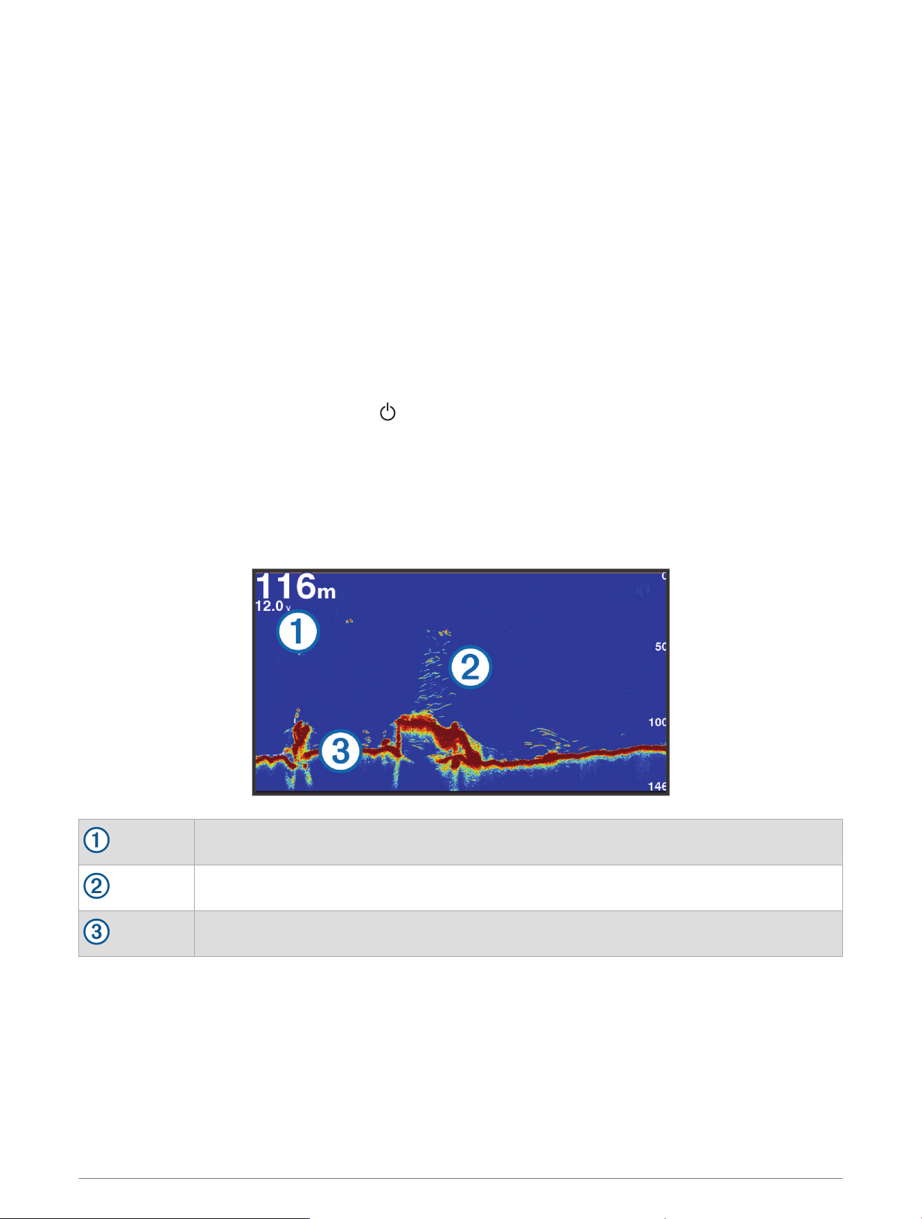
Sonar Fishfinder
When properly connected to a compatible transducer, your chartplotter can be used as a fishfinder.
For more information about which transducer is best for your needs, go to garmin.com/transducers.
Different sonar views can help you view the fish in the area. The sonar views available vary depending on the
type of transducer and sonar module connected to the chartplotter. For example, you can view certain Panoptix
™
sonar screens only if you have a compatible Panoptix transducer connected.
There are four basic styles of sonar views available: a full-screen view, a split-screen view that combines two
or more views, a split-zoom view, and a split-frequency view that displays two different frequencies. You can
customize the settings for each view in the screen. For example, if you are viewing the split-frequency view, you
can separately adjust the gain for each frequency.
If you do not see an arrangement of sonar views to suit your needs, you can create a custom combination
screen (Customizing with Combination Pages, page6).
Stopping the Transmission of Sonar Signals
• To disable the active sonar, from the sonar screen, select MENU > Transmit.
• To disable all sonar transmissions, press , and select Disable All Sonar Trans..
Traditional Sonar View
There are several full-screen views available, depending on the transducer that is connected.
The full-screen Traditional sonar view shows a large image of the sonar readings from a transducer. The range
scale along the right side of the screen shows the depth of detected objects as the screen scrolls from the right
to the left.
Depth information
Suspended targets or fish
Bottom of the body of water
Split-Frequency Sonar View
In the split-frequency sonar view, the two sides of the screen show a full-view graph of sonar data of different
frequencies. You can use this view if you have installed multiple transducers or a transducer that supports
multiple frequencies.
NOTE: When using a single-band CHIRP transducer connected to a supported chartplotter or sonar module, the
split-frequency sonar view alternates between the two frequencies, which slows the scroll speed. A channel
indicator appears next to the sonar frequency on each side of the screen to help identify this behavior.
40 Sonar Fishfinder
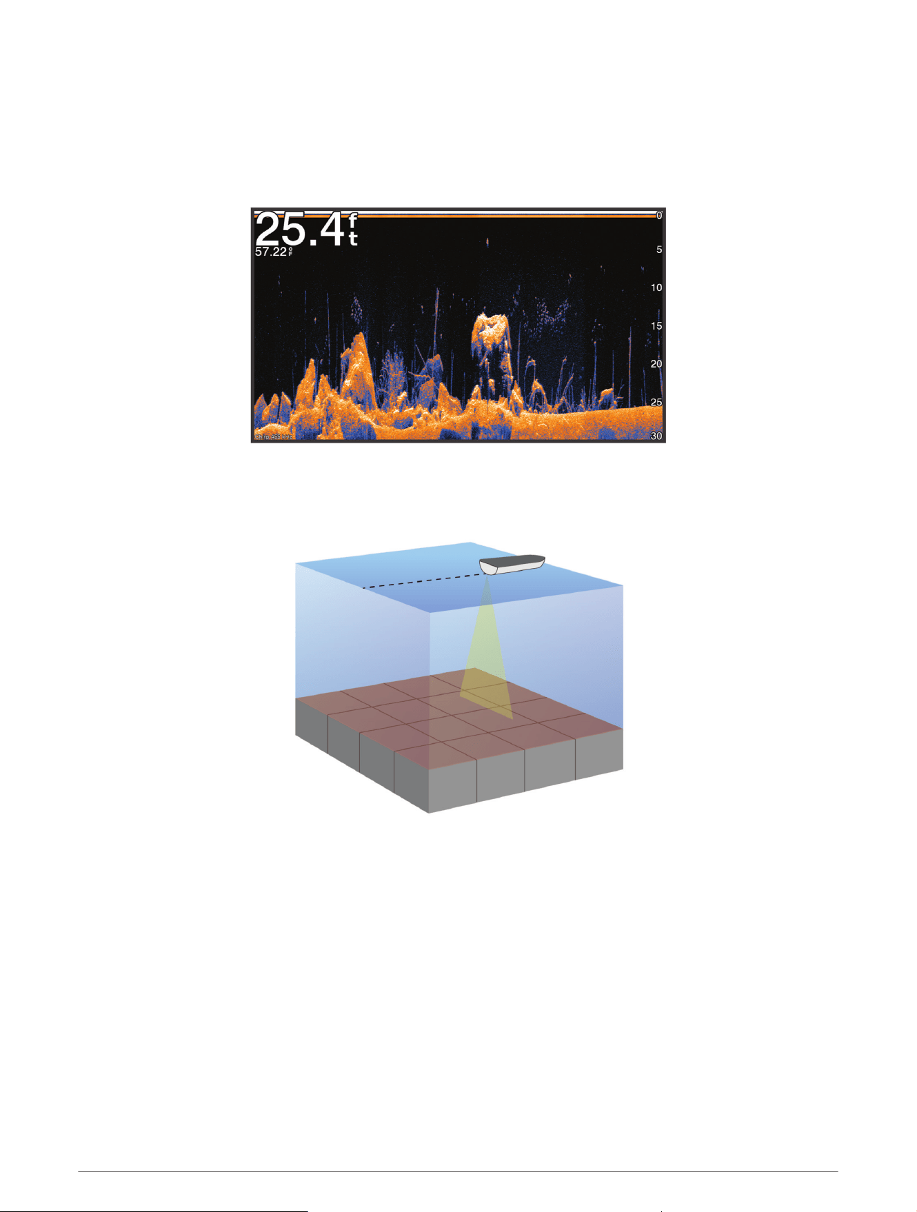
Garmin ClearVü
™
Sonar View
NOTE: To receive Garmin ClearVü scanning sonar, you need a compatible transducer. For information about
compatible transducers, go to garmin.com/transducers.
Garmin ClearVü high-frequency sonar provides a detailed picture of the fishing environment around the boat in a
detailed representation of structures the boat is passing over.
Traditional transducers emit a conical beam. The Garmin ClearVü scanning sonar technology emits a beam
similar to the shape of the beam in a copy machine. This beam provides a clearer, picture-like image of what is
beneath the boat.
Sonar Fishfinder 41
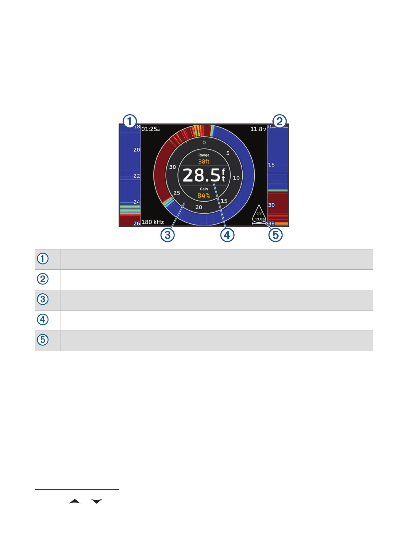
Flasher View
The flasher shows sonar information on a circular depth scale, indicating what is beneath your boat. It is
organized as a ring that starts at the top and progresses clockwise. Depth is indicated by the scale inside the
ring. Sonar information flashes on the ring when it is received at the depth indicated.
The flasher colors indicate different strengths of the sonar return. The default color scheme follows a traditional
sonar color palette, in which yellow indicates the strongest return, orange indicates a strong return, red indicates
a weaker return, and blue indicates the weakest return.
Select Sonar > Flasher.
A-scope, zoomed-in view of the right side view
A-scope with zoom area outlined
2
Depth scale
Depth at your present location
Angle and span of the transducer cone at the current frequency
Sonar Views in Combo Screens
You can add one or more available sonar views to a custom combination screen (Customizing with Combination
Pages, page6). If more than one source of sonar data is available, you can show sonar screens using different
sonar sources in separate windows of a custom combo screen.
If you have more than one source of sonar data available, you are prompted to select the source to use when
creating a custom combo. After you create the combo, you can change the source used in a window of the
combo screen later (Selecting a Sonar Source, page43).
2
You can press and to move the zoom area up and down.
42 Sonar Fishfinder
Selecting the Transducer Type
This chartplotter is compatible with a range of accessory transducers, including the Garmin ClearVü
transducers, which are available at garmin.com/transducers.
If you are connecting a transducer that was not included with the chartplotter, you may need to set the
transducer type to make the sonar function properly.
NOTE: Not all chartplotters and sonar modules support this feature.
1 Complete an action:
• From a sonar view, select MENU > Sonar Setup > Installation > Transducers.
• Select > My Vessel > Transducers.
2 Select the transducer that you want to change, and select Change Model.
3 Select an option:
• To enable the chartplotter to detect the transducer automatically, select Auto Detect.
• To select the transducer manually, select the option that matches the installed transducer, such as Dual
Beam (200/77 kHz) or Dual Freq (200/50 kHz).
NOTICE
Manually selecting a transducer could result in damage to the transducer or reduced transducer performance.
NOTE: If you select the transducer manually, disconnect that transducer, and then connect a different
transducer, you should reset this option to Auto Detect.
Selecting a Sonar Source
When you have more than one transducer providing data for a particular sonar view, you can select the source
to use for that sonar view. For example, if you have two transducers providing Garmin ClearVü data, you can
select the source to use for the Garmin ClearVü sonar view.
1 Open the sonar view for which you will change the source.
If the sonar view is in a combo screen, you must select the view you want to change.
2 Select MENU > Sonar Setup > Source.
3 Select the source for this sonar view.
Renaming a Sonar Source
You can rename a sonar source to easily identify that source. A sonar source is associated with the chartplotter
or sounder module with a connected transducer. For example, you can use "Bow" as the name of the
chartplotter installed on the bow of your boat with a connected transducer.
1 Select > Communications > BlueNet™ Network.
2 Select the chartplotter or sounder module you want to rename.
3 Select Change Name.
4 Enter the name.
Pausing and Resuming the Sonar Display
NOTE: Pausing the sonar display affects only the sonar view on the device where you pause the sonar display.
The transducer continues to transmit and receive sonar signals, and other connected displays continue to show
live sonar data.
From a sonar view, press the arrow key in the direction of the scrolling sonar.
To resume sonar scrolling after pausing, select BACK.
Sonar Fishfinder 43

Viewing Sonar History
You can scroll the sonar display to view historical sonar data.
NOTE: Not all transducers save historical sonar data.
1 From a sonar view, pause the sonar display (Pausing and Resuming the Sonar Display, page43).
2 Hold the arrow key in the direction of the scrolling sonar to view the history.
3 Select BACK to exit history and resume sonar scrolling.
Creating a Waypoint on the Sonar Screen
1 From a sonar view, pause the sonar display (Pausing and Resuming the Sonar Display, page43).
2 If necessary, scroll through the sonar display history until you find the location where you want to create a
waypoint.
3 Select a location on the sonar view where you want to create the waypoint.
4 Select .
5 If necessary, edit the waypoint information.
Adjusting the Level of Detail
You can control the level of detail and noise shown on the sonar screen either by adjusting the gain for
traditional transducers or by adjusting the brightness for Garmin ClearVü transducers.
If you want to see the highest intensity signal returns on the screen, you can lower the gain or brightness to
remove lower intensity returns and noise. If you want to see all return information, you can increase the gain or
brightness to see more information on the screen. This also increases noise, and can make it more difficult to
recognize actual returns.
1 From a sonar view, select MENU.
2 Select Gain or Brightness.
3 Select an option:
• To increase or decrease the gain or brightness manually, select Up or Down.
• To allow the chartplotter to adjust the gain or brightness automatically, select an automatic option.
Adjusting the Color Intensity
You can adjust the intensity of colors and highlight areas of interest on the sonar screen by adjusting the color
gain for traditional transducers or the contrast for some transducers. This setting works best after you have
adjusted the level of detail shown on the screen using the gain or brightness settings.
If you want to highlight smaller fish targets or create a higher intensity display of a target, you can increase
the color gain or contrast setting. This causes a loss in the differentiation of the high intensity returns at the
bottom. If you want to reduce the intensity of the return, you can reduce the color gain or contrast.
1 From a sonar view, select MENU.
2 Select an option based on sonar view:
• Select Contrast.
• Select Sonar Setup > Appearance > Color Gain.
3 Select an option:
• To increase or decrease the color intensity manually, select Up or Down.
• To use the default setting, select Default.
44 Sonar Fishfinder

Sonar Setup
NOTE: Not all options and settings apply to all models and transducers.
These settings apply to the following types of transducers.
• Traditional
• Garmin ClearVü
From a sonar view, select MENU > Sonar Setup.
Scroll Speed: Sets the rate at which the sonar scrolls from right to left (Setting the Scroll Speed, page46).
In shallow water, you can select a slower scroll speed to extend the length of time the information is
displayed on screen. In deeper water, you can select a faster scroll speed. Automatic scroll speed adjusts the
scrolling speed to the speed the boat is traveling.
Noise Reject: Reduces the interference and the amount of clutter shown on the sonar screen (Sonar Noise
Rejection Settings, page47).
Appearance: Configures the appearance of the sonar screen (Sonar Appearance Settings, page47).
Alarms: Sets sonar alarms (Sonar Alarms, page48).
Advanced: Configures various sonar display and data source settings (Advanced Sonar Settings, page48).
Installation: Configures the transducer (Transducer Installation Settings, page49).
Setting the Zoom Level on the Sonar Screen
1 From a sonar view, select MENU > Zoom > > Mode.
2 Select an option:
• To set the depth and zoom automatically, select Auto.
If necessary, select Set Zoom to modify the zoom setting. Select View Up or View Down to set the depth
range of the magnified area, and select Zoom In or Zoom Out to increase or decrease the magnification of
the magnified area.
• To set the depth range of the magnified area manually, select Manual.
If necessary, select Set Zoom to modify the zoom setting. Select View Up or View Down to set the depth
range of the magnified area, and select Zoom In or Zoom Out to increase or decrease the magnification of
the magnified area.
• To magnify one particular area of the screen, select Magnify.
If necessary, select Magnify to increase or decrease the magnification level.
TIP: You can drag the magnification box to a new location on the screen.
• To zoom in on the sonar data from the bottom depth, select Bottom Lock.
If necessary, select Span to adjust the depth and placement of the bottom lock area.
To cancel the zoom, deselect the Zoom option.
Enabling a Split Zoom Sonar View
When the zoom is set to Auto, Manual, or Bottom Lock, you can enable a split zoom view to show both the
standard view and the zoomed-in view side-by-side.
From a sonar view, select MENU > Zoom > > Split Zoom.
To disable the split zoom view, select Split Zoom again.
Sonar Fishfinder 45
Setting the Scroll Speed
You can set the rate at which the sonar image moves across the screen. A higher scroll speed shows more
detail until there is no additional detail to show, at which point it starts stretching out the existing detail. This
can be useful while moving or trolling, or when you are in very deep water where the sonar is pinging very slowly.
A lower scroll speed displays sonar information on the screen longer.
For most situations, the Default setting provides a good balance between a quickly scrolling image and less
distorted targets.
1 From a sonar view, select MENU > Sonar Setup > Scroll Speed.
2 Select an option:
• To adjust the scroll speed automatically using speed-over-ground, select Auto.
The Auto setting selects a scroll rate to match the boat speed, so targets in the water are drawn with
the correct aspect ratio and appear less distorted. When viewing Garmin ClearVü/SideVü sonar views or
searching for structure, it is recommend to use the Auto setting.
• To scroll faster, select Up.
• To scroll more slowly, select Down.
Adjusting the Range
You can adjust the range of the depth scale for traditional and Garmin ClearVü sonar views.
Allowing the device to adjust the range automatically keeps the bottom within the lower or outer third of the
sonar screen, and can be useful for tracking a bottom that has minimal or moderate terrain changes.
Manually adjusting the range enables you to view a specified range, which can be useful for tracking a bottom
that has large terrain changes, such as a drop-offs or cliffs. The bottom can appear on the screen as long as it
appears within the range you have set.
1 From a sonar view, select MENU > Range.
2 Select an option:
• To allow the chartplotter to adjust the range automatically, select Auto.
• To increase or decrease the range manually, select Up or Down.
TIP: From the sonar screen, you can select or to manually adjust the range.
TIP: You can select or simultaneously to switch between the automatic and manual adjustment
modes.
TIP: When viewing multiple sonar screens, you can select SELECT to choose the active screen.
TIP: When viewing a single sonar screen, you can select SELECT to change the shortcut for the and
keys. Pressing SELECT repeatedly allows you to choose Range, Gain, or Magnify level.
46 Sonar Fishfinder
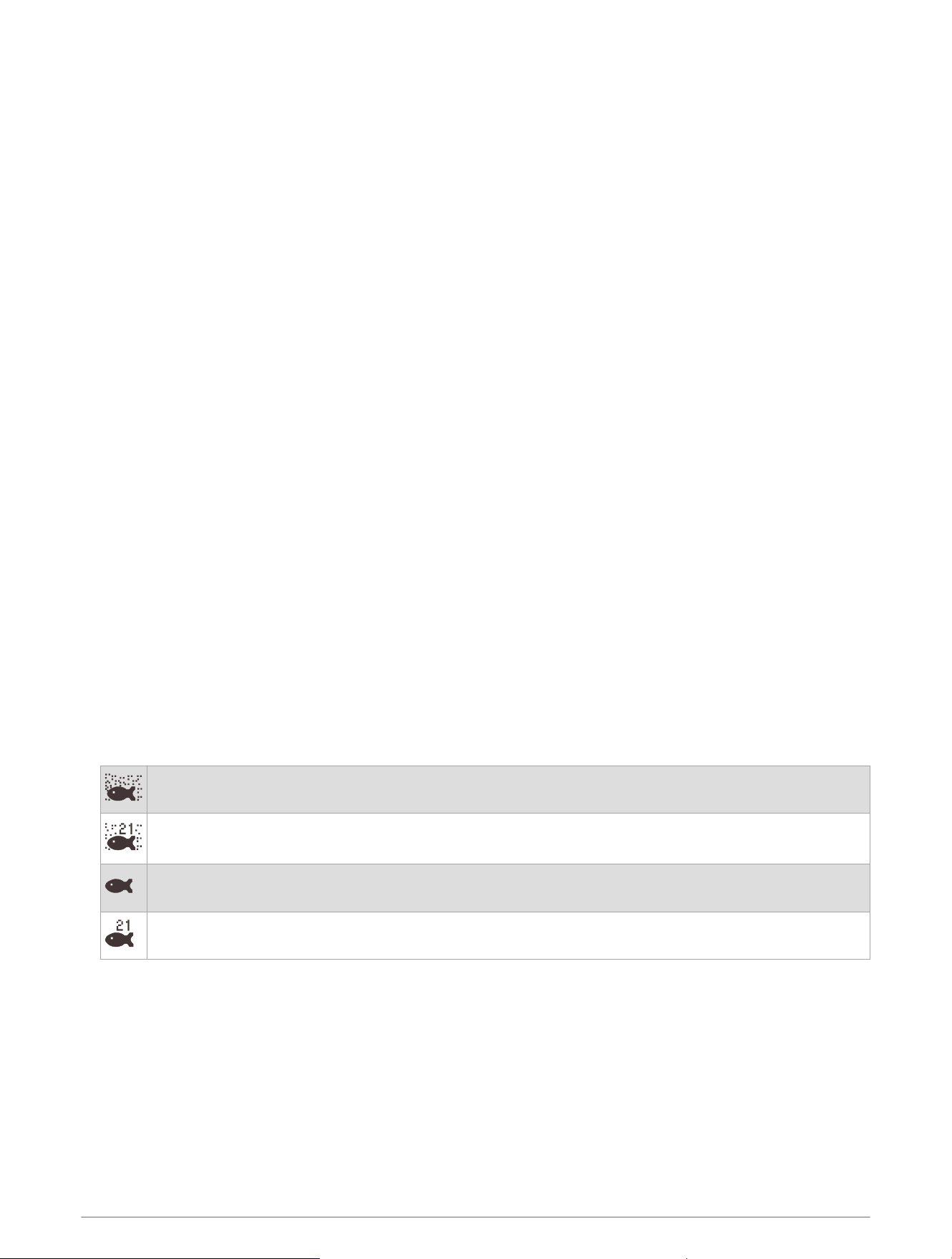
Sonar Noise Rejection Settings
From a sonar view, select MENU > Sonar Setup > Noise Reject.
Interference: Adjusts the sensitivity to reduce the effects of interference from nearby sources of noise.
The lowest interference setting that achieves the desired improvement should be used to remove
interference from the screen. Correcting installation issues that cause noise is the best way to eliminate
interference.
Color Limit: Hides part of the color palette to help eliminate fields of weak clutter.
By setting the color limit to the color of the undesired returns, you can eliminate the display of undesired
returns on the screen.
Smoothing: Removes noise that is not part of a normal sonar return, and adjusts the appearance of returns,
such as the bottom.
When smoothing is set to high, more of the low-level noise remains than when using the interference control,
but the noise is more subdued because of averaging. Smoothing can remove speckle from the bottom.
Smoothing and interference work well together to eliminate low-level noise. You can adjust the interference
and smoothing settings incrementally to remove undesirable noise from the display.
Surface Noise: Hides surface noise to help reduce clutter. Wider beam widths (lower frequencies) can show
more targets, but can generate more surface noise.
TVG: Adjusts the time varying gain, which can reduce noise.
This control is best used for situations when you want to control and suppress clutter or noise near the water
surface. It also allows for the display of targets near the surface that are otherwise hidden or masked by
surface noise.
Sonar Appearance Settings
From a sonar view, select MENU > Sonar Setup > Appearance.
Color Scheme: Sets the color scheme.
Color Gain: Adjusts the intensity of colors (Adjusting the Color Intensity, page44).
A-Scope: Displays a vertical flasher along the right side of the screen that shows instantaneously the range to
targets along a scale.
Depth Line: Shows a quick-reference depth line.
Edge: Highlights the strongest signal from the bottom to help define the hardness or softness of the signal.
Fish Symbols: Sets how the sonar interprets suspended targets.
Shows suspended targets as symbols and background sonar information.
Shows suspended targets as symbols with target depth information and background sonar informa
tion.
Shows suspended targets as symbols.
Shows suspended targets as symbols with target depth information.
Pic. Advance
: Allows the sonar picture to advance faster by drawing more than one column of data on the
screen for each column of sonar data received. This is especially helpful when you are using the sonar in
deep water, because the sonar signal takes longer to travel to the water bottom and back to the transducer.
The 1/1 setting draws one column of information on the screen per sonar return. The 2/1 setting draws two
columns of information on the screen per sonar return, and so on for the 4/1 and 8/1 settings.
Overlay Data: Sets the data shown on the sonar screen.
Sonar Fishfinder 47
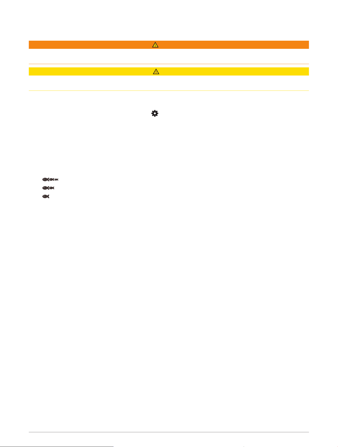
Sonar Alarms
WARNING
The sonar alarms feature is a tool for situational awareness only and may not prevent grounding in all
circumstances. It is your obligation to ensure safe operation of the vessel.
CAUTION
The Beeper setting must be turned on to make alarms audible (Sounds and Display Settings, page55). Failure
to set audible alarms could lead to injury or property damage.
NOTE: Not all options are available on all transducers.
From an applicable sonar view, select MENU > Sonar Setup > Alarms.
You can also open the sonar alarms by selecting > Alarms > Sonar.
Shallow Water: Sets an alarm to sound when the depth is less than the specified value.
Deep Water: Sets an alarm to sound when the depth is greater than the specified value.
Water Temp.: Sets an alarm to sound when the transducer reports a temperature that is 2°F (1.1°C) above or
below the specified temperature.
Contour: Sets an alarm to sound when the transducer detects a suspended target within the specified depth
from the surface of the water and from the bottom.
Fish: Sets an alarm to sound when the device detects a suspended target.
• sets the alarm to sound when fish of all sizes are detected.
• sets the alarm to sound only when medium or large fish are detected.
• sets the alarm to sound only when large fish are detected.
Advanced Sonar Settings
From a Traditional sonar view, select MENU > Sonar Setup > Advanced.
Btm. Srch. Limit: Limits the search for the bottom to the depth selected when the Range setting is set to Auto.
To minimize the length of time it takes to find the bottom, you can select a depth to limit the search for the
bottom. The device will not search for the bottom deeper than the selected depth.
Range Sync > Off: The range for all sonar views in a combo screen are independent of one another.
Range Sync > On: This setting option is available only when viewing a combo screen using at least two
traditional and Garmin ClearVü views in a combo screen. The range is synchronized for all traditional and
Garmin ClearVü views in the combo screen.
Range Sync > Same Transducer Only: This is the default setting. The ranges are synchronized for views from
each transducer in the combo screen, but not between different transducers.
NOTE: This setting does not apply to a dual-band CHIRP transducer.
Scroll Sync: This setting option is available only when viewing a combo screen using at least two traditional
and Garmin ClearVüsonar views in a combo screen. The scroll rates are synchronized for all traditional and
Garmin ClearVü views in the combo screen.
48 Sonar Fishfinder
Transducer Installation Settings
These settings apply to the following types of sonar.
• Traditional
• Garmin ClearVü
From an applicable sonar view, select an option.
• From a Traditional sonar view, select MENU > Sonar Setup > Installation.
• From a Garmin ClearVü sonar view, select MENU > ClearVü Setup > Installation.
Restore Sonar Defaults: Restores the sonar settings to the factory default values.
Transducers: View details about installed transducers and save details to a memory card.
Transducers > Change Model: Allows you to change an installed transducer type (Selecting the Transducer
Type, page43).
Transducers > Manual Configuration: Allows you to set manual transducer configuration parameters on a
compatible sonar module. See the installation instructions for your compatible sonar module for more details
on connecting and manually configuring a transducer.
Sonar Frequencies
NOTE: The frequencies available depend on the transducers being used.
Adjusting the frequency helps adapt the sonar for your particular goals and the present depth of the water.
Higher frequencies use narrow beam widths, and are better for high-speed operation and rough sea conditions.
Bottom definition and thermocline definition can be better when using a higher frequency.
Lower frequencies use wider beam widths, which can let the fisherman see more targets, but could also
generate more surface noise and reduce bottom signal continuity during rough sea conditions. Wider beam
widths generate larger arches for fish target returns, making them ideal for locating fish. Wider beam widths
also perform better in deep water, because the lower frequency has better deep water penetration.
CHIRP frequencies allow you to sweep each pulse through a range of frequencies, resulting in better target
separation in deep water. CHIRP can be used to distinctly identify targets, like individual fish in a school, and
for deep water applications. CHIRP generally performs better than single frequency applications. Because some
fish targets may show up better using a fixed frequency, you should consider your goals and water conditions
when using CHIRP frequencies.
Some transducers also provide the ability to customize preset frequencies for each transducer element, which
enables you to change the frequency quickly using the presets as the water and your goals change.
Viewing two frequencies concurrently using the split-frequency view allows you to see deeper with the lower
frequency return and, at the same time, see more detail from the higher frequency return.
NOTICE
Always be aware of local regulations on sonar frequencies. For example, to protect orca whale pods, you might
be prohibited from using frequencies between 50 to 80kHz within
1
/
2
mile of an orca whale pod. It is your
responsibility to use the device in compliance with all applicable laws and ordinances.
Selecting the Transducer Frequency
NOTE: You cannot adjust the frequency for all sonar views and transducers.
You can select which frequencies appear on the sonar screen.
NOTICE
Always be aware of local regulations on sonar frequencies. For example, to protect orca whale pods, you might
be prohibited from using frequencies between 50 to 80kHz within ½ mile of an orca whale pod. It is your
responsibility to use the device in compliance with all applicable laws and ordinances.
1 From a sonar view, select MENU > Frequency.
2 Select a frequency suited to your needs and water depth.
For more information on frequencies, see Sonar Frequencies, page49.
Sonar Fishfinder 49
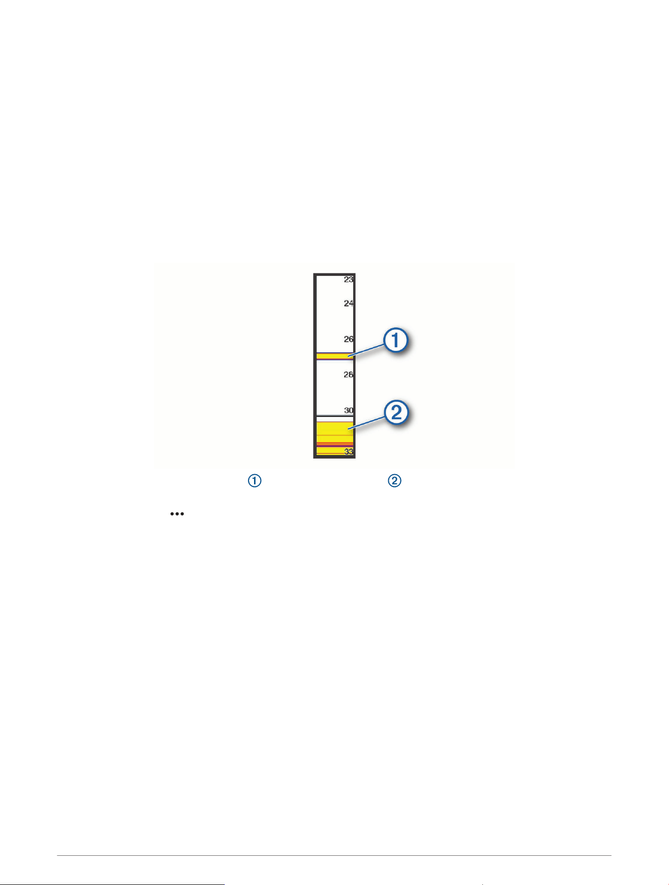
Creating a Frequency Preset
NOTE: Not available with all transducers.
You can create a preset to save a specific sonar frequency, which allows you to change frequencies quickly.
1 From a sonar view, select MENU > Frequency.
2 Select Manage Frequencies > New Preset.
3 Enter a frequency.
Turning On the A-Scope
NOTE: This feature is available in the Traditional sonar views.
The a-scope is a vertical flasher along the right side of the view, showing you what is underneath the transducer
right now. You can use the a-scope to identify target returns that may be missed when the sonar data is
quickly scrolling across the screen, such as when your boat is moving at high speeds. It can also be helpful for
detecting fish that are close to the bottom.
The a-scope above shows fish returns and a soft bottom return .
1 From a sonar view, select MENU > Sonar Setup > Appearance > A-Scope.
2 If necessary, select > Peak Hold to adjust the length of time the sonar returns are displayed.
Gauges and Graphs
The gauges and graphs provide various information about the engine and environment. To view the information,
a compatible transducer or sensor must be connected to the network.
50 Gauges and Graphs
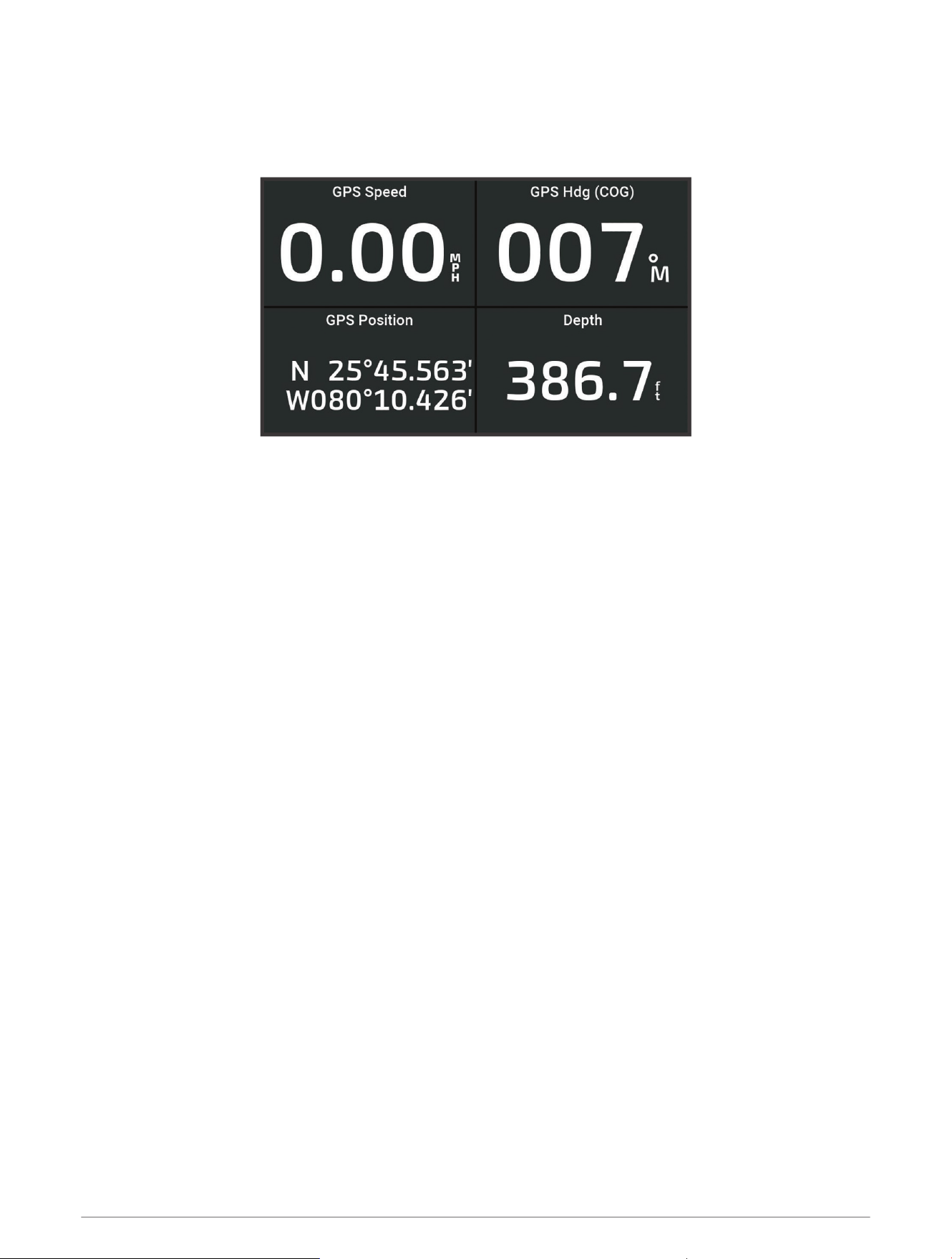
Viewing the Gauges
1 Select Gauges.
2 Select a gauge, such as Vessel.
Changing the Data Shown in a Gauge
1 Open a gauge page.
2 Select MENU > Edit Gauge Pages.
3 Select a gauge to edit.
4 Select Replace Data.
5 Select a data type.
6 Select the data to display.
Customizing the Gauges
You can add a gauge page, change the layout of the gauge page, change how the gauges are displayed, and
change the data in each gauge.
1 Open a gauge page.
2 Select MENU > Edit Gauge Pages.
3 If necessary, select a gauge view or gauge to edit.
4 Select an option:
• To change the data shown in a gauge, select the gauge and select Replace Data.
• To change the layout of the gauges on the page, select Change Layout.
• To add a page to this set of gauge pages, select Add Page.
• To restore this page to the original view, select Restore Default View.
Viewing Trip Gauges
Trip gauges show information for odometer, speed, time, and fuel for your present trip.
Select Gauges > Trip.
Gauges and Graphs 51

Resetting Trip Gauges
1 Select MENU.
2 Select an option:
• To set all the readings for the present trip to zero, select Reset Trip.
• To set the maximum speed reading to zero, select Reset Maximum Speed.
• To set the odometer reading to zero, select Reset Odometer.
• To set all the readings to zero, select Reset All.
Viewing Graphs
Before you can view graphs of various environmental changes, such as temperature and depth, you must have
an appropriate transducer connected to the device.
You can view graphs of sensor data by creating a new Combo page or by adding a graph to an existing Combo
page.
1 Create a new Combo page or open an existing Combo page (Customizing with Combination Pages, page6).
2 Select the window where you want to add a graph, and select Graphs.
3 Select the graph you want to add.
TIP: You can change the graph in an active combo window by selecting MENU > Change Graph, and selecting a
new graph.
Setting the Graph Range and Time Scales
You can indicate the amount of time and the range of sensor data that appears in the depth, wind, and water
temperature graphs.
1 Select a graph in a Combo page, and select MENU.
2 Select an option:
• To set a time-elapsed scale, select Duration. The default setting is 10 minutes. Increasing the time-
elapsed scale allows you to view variations over a longer period of time. Decreasing the time-elapsed
scale allows you to view more detail over a shorter period of time.
• To set the graph scale, select Scale. Increasing the scale allows you to view more variation in readings.
Decreasing the scale allows you to view more detail in the variation.
52 Gauges and Graphs
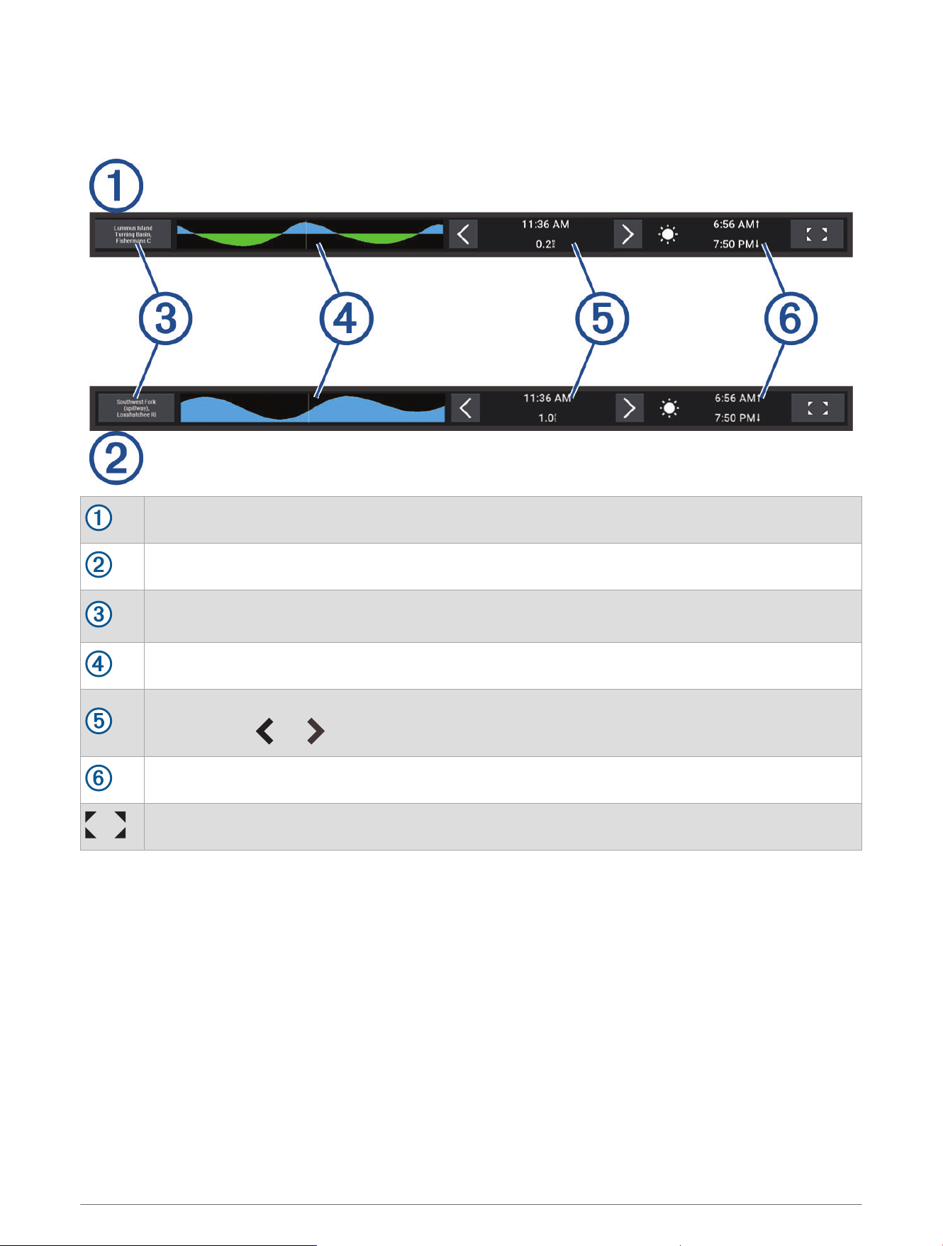
Tide, Current, and Celestial Information
Tide and Current Overlays
Tide station overlay bar.
Current station overlay bar.
Name of the selected tide or current station.
Select to change to a different tide or current station.
Tide or current station graph.
Present time, indicated on the tide or current station graph as a white line.
You can select and to adjust the time on the tide or current station graph.
Present sunrise and sunset times.
Select to open the tide or current station information page.
Adding Tide and Current Overlays
1 From the page where you want to add the overlay, select MENU > Edit Overlays.
2 Select Top Bar, Bottom Bar, Left Bar, or Right Bar.
3 Select Tides or Currents.
Tide, Current, and Celestial Information 53
Tide Station Information
WARNING
Tide and current information is for information purposes only. It is your responsibility to heed all posted
water-related guidance, to remain aware of your surroundings, and to use safe judgment in, on, and around the
water at all times. Failure to heed this warning could result in property damage, serious personal injury, or death.
You can view information about a tide station for a specific date and time, including the tide height, and
when the next high and low tides will occur. By default, the Tides overlay bar on the chartplotter shows tide
information for the most recently viewed tide station, present date, and past hour.
From the Tides overlay bar, select .
Current Station Information
WARNING
Tide and current information is for information purposes only. It is your responsibility to heed all posted
water-related guidance, to remain aware of your surroundings, and to use safe judgment in, on, and around the
water at all times. Failure to heed this warning could result in property damage, serious personal injury, or death.
NOTE: Current station information is available with certain detailed maps.
You can view information about a current station for a specific date and time, including the current speed and
level of the current. By default, the Currents overlay bar on the chartplotter shows current information for the
most recently viewed current station and for the present date and time (Tide and Current Overlays, page53).
From the Currents overlay bar, select .
Celestial Information
You can view information about sunrise, sunset, moonrise, moonset, moon phase, and the approximate sky view
location of the sun and moon. The center of the screen represents the sky overhead, and the outermost rings
represent the horizon. By default, the chartplotter shows celestial information for the present date and time.
From the Tides or Currents overlay bar, select , then select Celestial.
Viewing Tide Station, Current Station, or Celestial Information for a Different Date
1 From a Tides or Currents overlay bar, select .
2 To view celestial information, select Celestial.
3 Select an option:
• To view information for a different date, select Change Date, and enter a date.
• To view information for today, select Current Date and Time.
• If available, to view information for the day after the date shown, select Next Day.
• If available, to view information for the day before the date shown, select Previous Day.
Viewing Information for a Different Tide or Current Station
1 From a Tides or Currents overlay bar, select .
2 Select Nearby Stations.
3 Select a station.
Viewing Almanac Information from the Navigation Chart
1 From a chart or 3D chart view, select a tide station or a current station icon.
2 Select the name of the station.
54 Tide, Current, and Celestial Information

Device Configuration
System Settings
Select > System.
Sounds and Display: Adjusts the display settings and the audio settings (if available).
Satellite Positioning: Provides information about the GPS satellites and settings.
System Information: Provides information about the devices on the network and the software version.
Auto Power Up: Controls which devices turn on automatically when power is applied.
Auto Power Off: Automatically turns off the system after it has been asleep for the selected length of time.
Simulator: Turns the simulator on or off and allows you to set the time, date, speed, and simulated location.
Sounds and Display Settings
Select > System > Sounds and Display.
Beeper: Turns on and off the tone that sounds for alarms and selections.
Backlight: Sets the backlight brightness. You can select the Auto option to adjust the backlight brightness
automatically based on the ambient light.
Color Mode: Sets the device to display day or night colors. You can select the Auto option to allow the device to
set day or night colors automatically based on the time of day.
Startup Image: Sets the image that appears when you turn on the device.
Startup Layout: Sets the layout that appears when you turn on the device.
Satellite Positioning (GPS) Settings
Select > System > Satellite Positioning.
Source: Allows you to select the preferred source for GPS data.
Speed Filter: Averages the speed of your vessel over a short period of time for smoother speed values.
WAAS/EGNOS: Turns on or off WAAS data (in North America) or EGNOS data (in Europe), which can provide
more-accurate GPS position information. When using WAAS or EGNOS data, the device may take longer to
acquire satellites.
Positioning Mode > GPS Only: The GPS source uses only GPS satellites for position data.
Positioning Mode > GPS and GLONASS: The GPS source uses both GPS satellites and GLONASS (Russia
satellite system) for position data. When the system is used in situations with poor sky visibility, GLONASS
data can be used in combination with GPS to provide more accurate position information.
Positioning Mode > Multi-Constellation: The GPS source uses GPS data from all available satellite
constellations for position data.
Positioning Mode > Multi-Constellation and Multi-Frequency: The GPS source uses GPS data from all available
satellite constellations as well as both L1 and L5 frequencies for position data.
Viewing System Software Information
You can view the software version, the basemap version, all supplemental map information (if applicable), and
the unit ID number. You may need this information to update the system software or to purchase additional map
data information.
Select > System > System Information > Software Information.
Viewing the Event Log
The event log shows a list of system events.
1 Select > System > System Information > Event Log.
2 If necessary, select an event in the list, and select Review to view more information about the event.
Device Configuration 55

Sorting and Filtering Events
1 From the Event Log, select Sort By.
2 Select an option to sort or filter the event log.
Saving Events to a Memory Card
1 Insert a memory card into the card slot.
2 From the Event Log, select Save to Card.
Clearing All of the Events From the Event Log
From the Event Log, select Clear Event Log.
Viewing E-label Regulatory and Compliance Information
The label for this device is provided electronically. The e-label may provide regulatory information, such as
identification numbers provided by the FCC or regional compliance markings, as well as applicable product and
licensing information. Not available on all models.
1 Select .
2 Select System.
3 Select Regulatory Information.
Preferences Settings
Select > Preferences.
Units: Sets units of measure.
Language: Sets the on-screen text language.
Navigation: Sets navigation preferences.
Keyboard Layout: Arranges the keys on the on-screen keyboard.
Screenshot Capture: Allows the device to save images of the screen.
Units Settings
Select > Preferences > Units.
System Units: Sets the unit format for the device. For example, Custom > Depth > Fathoms sets the unit format
for depth to Fathoms.
Variance: Sets the magnetic declination, the angle between magnetic north and true north, for your present
location.
North Reference: Sets the direction references used in calculating heading information. True sets geographic
north as the north reference. Grid sets grid north as the north reference (000º). Magnetic sets the magnetic
north as the north reference.
Position Format: Sets the position format in which a given location reading appears. Do not change this setting
unless you are using a map or chart that specifies a different position format.
Map Datum: Sets the coordinate system on which the map is structured. Do not change this setting unless you
are using a map or chart that specifies a different map datum.
Time: Sets the time format, time zone, and daylight saving time.
56 Device Configuration

Navigation Settings
NOTE: Some settings and options require additional charts or hardware.
Select > Preferences > Navigation.
Route Labels: Sets the type of labels shown with route turns on the map.
Turn Transition: Adjusts how the chartplotter transitions to the next turn or leg or the route. You can set the
transition to be based on time or distance before the turn. You can increase the time or distance value to help
improve the accuracy of the autopilot when navigating a route or an Auto Guidance line with many frequent
turns or at higher speeds. For straighter routes or slower speeds, lowering this value can improve autopilot
accuracy.
Speed Sources: Sets the source for the speed readings.
Auto Guidance: Sets the measurements for the Preferred Depth, Vertical Clearance, and Shoreline Distance,
when you are using some premium maps.
Route Start: Selects a starting point for route navigation.
Auto Guidance Path Configurations
CAUTION
The Preferred Depth and Vertical Clearance settings influence how the chartplotter calculates an Auto Guidance
path. If a section of an Auto Guidance path is shallower than the Preferred Depth or lower than the Vertical
Clearance settings, the section of the Auto Guidance path appears as a solid orange line or a red striped line
in Garmin Navionics+ and Garmin Navionics Vision+ charts and appears as a magenta and gray striped line in
previous versions. When your boat enters one of those areas, a warning message appears (Route Color Coding,
page27).
NOTE: Auto Guidance is available with premium charts, in some areas.
NOTE: Not all settings apply to all maps.
You can set the parameters the chartplotter uses when calculating an Auto Guidance path.
Select > Preferences > Navigation > Auto Guidance.
Preferred Depth: Sets the minimum water depth, based on chart depth data, that your boat can safely travel
over.
NOTE: The minimum water depth for the premium charts (made before 2016) is 3 feet. If you enter a value of
less than 3 feet, the charts only use depths of 3 feet for Auto Guidance path calculations.
Vertical Clearance: Sets the minimum height of a bridge or obstacle, based on chart data, that your boat can
safely travel under.
Shoreline Distance: Sets how close to the shore you want the Auto Guidance path to be placed. The path
may move if you change this setting while navigating. The available values for this setting are relative, not
absolute. To ensure that path is placed the appropriate distance from shore, you can assess the placement
of the path using one or more familiar destinations that require navigation through a narrow waterway
(Adjusting the Distance from Shore, page36).
Device Configuration 57
Adjusting the Distance from Shore
The Shoreline Distance setting indicates how close to the shore you want the Auto Guidance line to be placed.
The Auto Guidance line may move if you change this setting while navigating. The available values for the
Shoreline Distance setting are relative, not absolute. To ensure the Auto Guidance line is placed the appropriate
distance from shore, you can assess the placement of the Auto Guidance line using one or more familiar
destinations that require navigation through a narrow waterway.
1 Dock your vessel or drop the anchor.
2 Select > Preferences > Navigation > Auto Guidance > Shoreline Distance > Normal.
3 Select a destination that you have navigated to previously.
4 Select Navigate To > Auto Guidance.
5 Review the placement of the Auto Guidance line, and determine whether the line safely avoids known
obstacles and the turns enable efficient travel.
6 Select an option:
• If the placement of the line is satisfactory, select MENU > Navigation Options > Stop Navigation, and
proceed to step 10.
• If the line is too close to known obstacles, select > Preferences > Navigation > Auto Guidance >
Shoreline Distance > Far.
• If the turns in the line are too wide, select > Preferences > Navigation > Auto Guidance > Shoreline
Distance > Near.
7 If you selected Near or Far in step 6, review the placement of the Auto Guidance line, and determine whether
the line safely avoids known obstacles and the turns enable efficient travel.
Auto Guidance maintains a wide clearance from obstacles in open water, even if you set the Shoreline
Distance setting to Near or Nearest. As a result, the chartplotter may not reposition the Auto Guidance line,
unless the destination selected requires navigation through a narrow waterway.
8 Select an option:
• If the placement of the line is satisfactory, select MENU > Navigation Options > Stop Navigation, and
proceed to step 10.
• If the line is too close to known obstacles, select > Preferences > Navigation > Auto Guidance >
Shoreline Distance > Farthest.
• If the turns in the line are too wide, select > Preferences > Navigation > Auto Guidance > Shoreline
Distance > Nearest.
9 If you selected Nearest or Farthest in step 8, review the placement of the Auto Guidance line, and determine
whether the line safely avoids known obstacles and the turns enable efficient travel.
The Auto Guidance path maintains a wide clearance from obstacles in open water, even if you set the
Shoreline Distance setting to Near or Nearest. As a result, the chartplotter may not reposition the Auto
Guidance line, unless the destination selected requires navigation through a narrow waterway.
10 Repeat steps 3 through 9 at least once more, using a different destination each time, until you are familiar
with the functionality of the Shoreline Distance setting.
Communications Settings
Viewing Connected Devices
You can view lists of the connected devices on the vessel including which chartplotter a device is connected to
or paired with.
1 Select > Communications.
2 Select a network.
3 Select Device List.
A list of network devices appears. If a device is connected to or paired with a specific chartplotter, the name
of the chartplotter is shown along with the device name.
58 Device Configuration
Setting Alarms
CAUTION
The Beeper setting must be turned on to make alarms audible (Sounds and Display Settings, page55). Failure to
set audible alarms could lead to injury or property damage.
Navigation Alarms
Select > Alarms > Navigation.
Arrival: Sets an alarm to sound when you are within a specified distance or time from a turn or a destination.
Anchor Drag: Sets an alarm to sound when you exceed a specified drift distance while anchored.
WARNING
The anchor drag alarm is a tool for situational awareness only and may not prevent groundings or collisions in
all circumstances. You are responsible for the safe and prudent operation of your vessel, for remaining aware of
your surroundings, and for using safe judgment on the water at all times.
Off Course: Sets an alarm to sound when you are off course by a specified distance.
Boundary Alarms: Disables and enables all boundary alarms.
Setting the Anchor Drag Alarm
You can set an alarm to sound if you have moved outside an allowable radius you set when configuring the
alarm.
WARNING
The anchor drag alarm is a tool for situational awareness only, and may not prevent grounding or collisions in
all circumstances. You are responsible for the safe and prudent operation of your vessel, for remaining aware
of your surroundings, and for using safe judgement on the water at all times. Failure to heed this warning could
result in property damage, serious personal injury, or death.
CAUTION
The Beeper setting must be turned on to make alarms audible (Sounds and Display Settings, page55). Failure to
set audible alarms could lead to injury or property damage.
1 Select > Alarms > Navigation > Anchor Drag.
2 Select Alarm to turn on the alarm.
3 Select Set Radius, and select a distance on the chart.
4 Select BACK.
Device Configuration 59
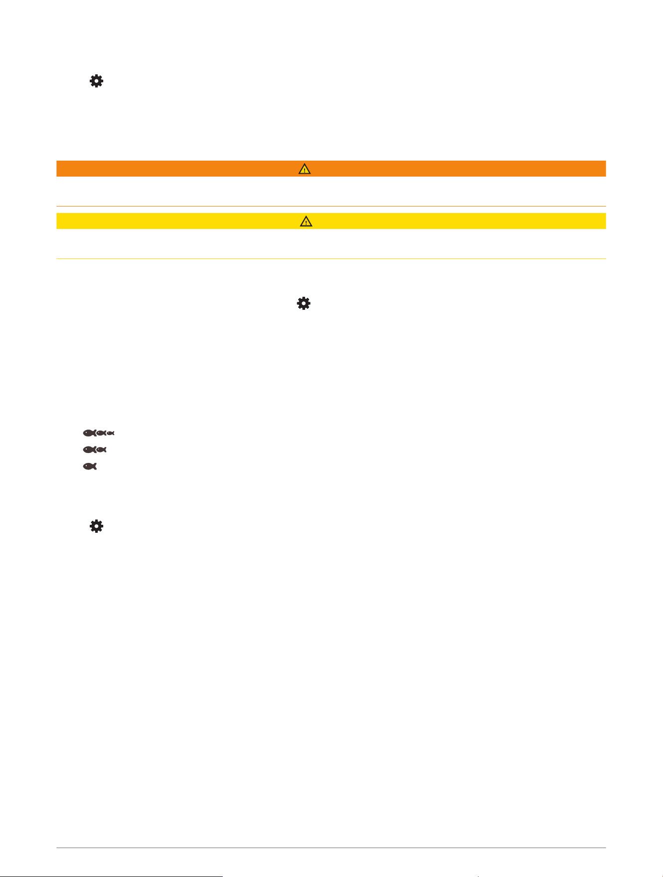
System Alarms
Select > Alarms > System.
Unit Voltage: Sets an alarm to sound when the battery reaches a specified low voltage.
GPS Accuracy: Sets an alarm to sound when the GPS location accuracy falls outside the user-defined value.
Sonar Alarms
WARNING
The sonar alarms feature is a tool for situational awareness only and may not prevent grounding in all
circumstances. It is your obligation to ensure safe operation of the vessel.
CAUTION
The Beeper setting must be turned on to make alarms audible (Sounds and Display Settings, page55). Failure to
set audible alarms could lead to injury or property damage.
NOTE: Not all options are available on all transducers.
From an applicable sonar view, select MENU > Sonar Setup > Alarms.
You can also open the sonar alarms by selecting > Alarms > Sonar.
Shallow Water: Sets an alarm to sound when the depth is less than the specified value.
Deep Water: Sets an alarm to sound when the depth is greater than the specified value.
Water Temp.: Sets an alarm to sound when the transducer reports a temperature that is 2°F (1.1°C) above or
below the specified temperature.
Contour: Sets an alarm to sound when the transducer detects a suspended target within the specified depth
from the surface of the water and from the bottom.
Fish: Sets an alarm to sound when the device detects a suspended target.
• sets the alarm to sound when fish of all sizes are detected.
• sets the alarm to sound only when medium or large fish are detected.
• sets the alarm to sound only when large fish are detected.
My Vessel Settings
NOTE: Some settings and options require additional charts or hardware.
Select > My Vessel.
Transducers: Shows all transducers on the network, allows you to change transducers, and allows you to view
diagnostic information (Selecting the Transducer Type, page43).
Temp. Offset: Allows you to set an offset value to compensate for the water temperature reading from a
connected water-temperature sensor or a temperature-capable transducer (Setting the Water Temperature
Offset, page61).
Hull ID Number: Allows you to enter the Hull Identification Number (HIN).The HIN might be permanently affixed
to the upper starboard side of the transom or outboard side.
60 Device Configuration
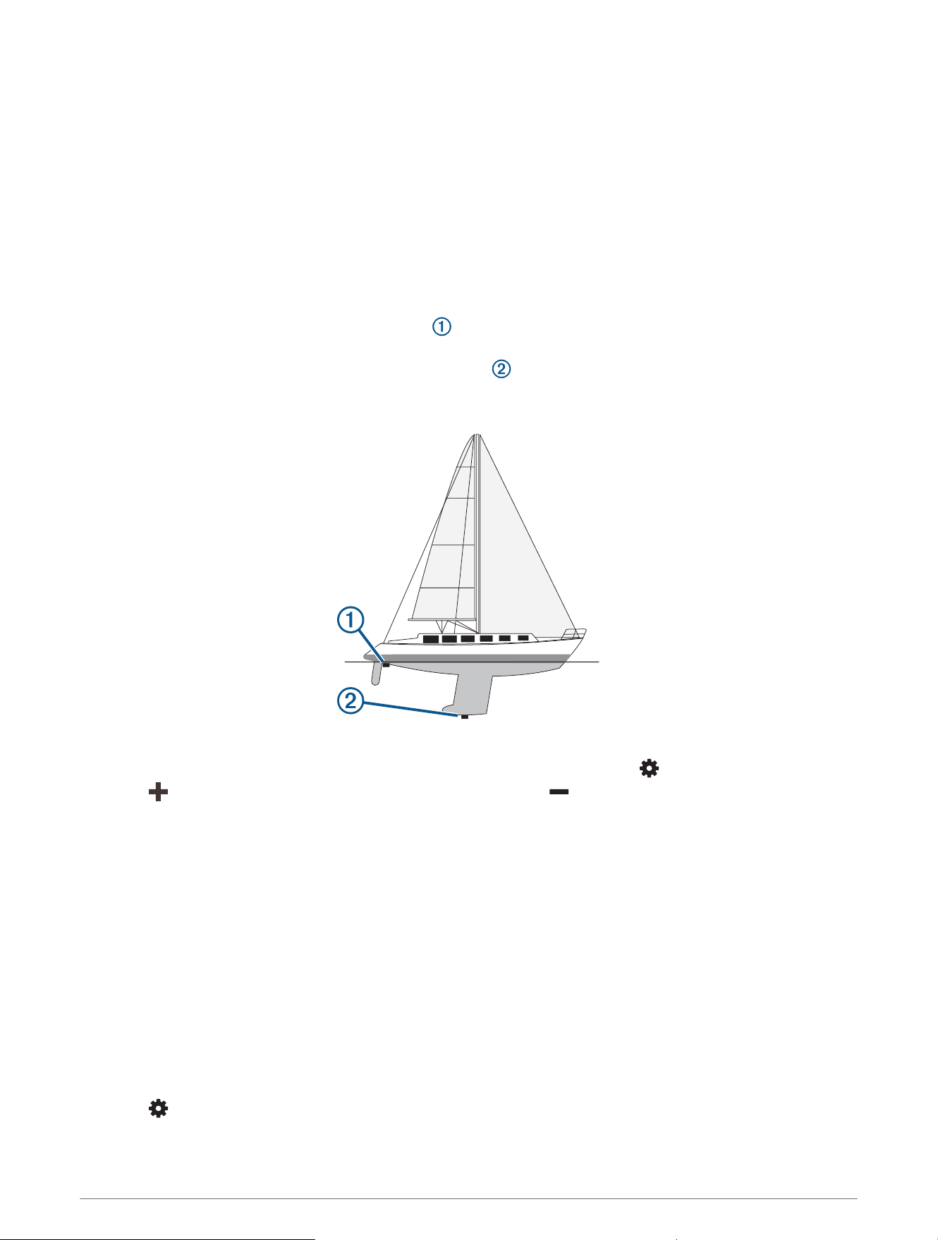
Setting the Keel Offset
You can enter a keel offset to compensate the water depth reading for the transducer installation location. This
allows you to view the depth of the water below the keel or the true depth of the water, depending on your
needs.
If you want to know the water depth below the keel or the lowest point of your boat and the transducer is
installed at the water line or anywhere above the end of the keel, measure the distance from the transducer
location to the keel of the boat.
If you want to know the true water depth and the transducer is installed below the water line, measure the
distance from the bottom of the transducer up to the water line.
NOTE: This option is only available when you have valid depth data.
1 Measure the distance:
• If the transducer is installed at the water line or anywhere above the end of the keel, measure the
distance from the transducer location to the keel of the boat. Enter this value as a positive number.
• If the transducer is installed at the bottom of the keel and you want to know the true depth of the
water, measure the distance from the transducer to the water line. Enter this value in as a negative
number.
2 Complete an action:
• If the transducer is connected to the chartplotter or a sonar module, select > My Vessel > Keel Offset.
3 Select if the transducer is installed at the water line, or select if the transducer is installed at the
bottom of the keel.
4 Use the arrow keys to enter the keel offset measured in step 1.
Setting the Water Temperature Offset
The temperature offset compensates for the temperature reading from a temperature sensor or temperature-
capable transducer.
1 Measure the water temperature using the temperature sensor or temperature-capable transducer that is
connected to the network.
2 Measure the water temperature using a different temperature sensor or a thermometer that is known to be
accurate.
3 Subtract the water temperature measured in step 1 from the water temperature measured in step 2.
This value is the temperature offset. Enter this value in step 5 as a positive number if the sensor measures
the water temperature as being colder than it actually is. Enter this value in step 5 as a negative number if the
sensor measures the water temperature as being warmer than it actually is.
4 Select > My Vessel > Temp. Offset.
5 Enter the temperature offset value calculated in step 3.
Device Configuration 61
Restoring the Original Chartplotter Factory Settings
NOTE: This affects all devices on the network.
1 Select > System > System Information > Reset.
2 Select an option:
• To reset the device settings to the factory default values, select Reset Default Settings. This restores the
default configuration settings, but does not remove saved user data, maps, or software updates.
• To clear saved data, such as waypoints and routes, select Delete User Data. This does not affect maps or
software updates.
• To clear saved data and reset device settings to the factory default values, disconnect the chartplotter
from the Garmin Marine Network, and select Delete Data and Reset Settings. This does not affect maps
or software updates.
Sharing and Managing User Data
WARNING
This feature allows you to import data from other devices that may have been generated by third parties.
Garmin makes no representations about the accuracy, completeness, or timeliness of data that is generated by
third parties. Any reliance on or use of such data is at your own risk.
You can share user data between compatible devices. User data includes waypoints, saved tracks, routes, and
boundaries.
• You can share and manage user data between different devices using a memory card. The memory card you
use must be formatted to a file type supported by all devices that you want to share user data. For example,
if you have one device that supports only FAT32 format cards and another device that supports exFat format
cards, you should use a card formatted to FAT32 so that it can be read by both devices (Inserting Memory
Cards, page4).
Selecting a File Type for Third-Party Waypoints and Routes
You can import and export waypoints and routes from third-party devices.
1 Insert a memory card into the card slot.
2 Select > Manage User Data > Data Transfer > File Type.
3 Select GPX.
To transfer data with Garmin devices again, select the ADM file type.
Copying User Data from a Memory Card
You can transfer user data from a memory card to transfer from other devices.
1 Insert a memory card into a card slot.
2 Select > Manage User Data > Data Transfer.
3 If necessary, select the memory card to copy data to.
4 Select an option:
• To transfer data from the memory card to the chartplotter and combine it with existing user data, select
Merge from Card.
• To transfer data from the memory card to the chartplotter and overwrite existing user data, select Replace
from Card.
5 Select the file name.
62 Sharing and Managing User Data

Copying All User Data to a Memory Card
You can save all of the user data on the device to a memory card to transfer to other devices.
1 Insert a memory card into the card slot.
2 Select > Manage User Data > Data Transfer > Save All to Card.
3 If necessary, select the memory card to copy the data to.
4 Select an option:
• To create a new file, select Add New File, and enter a name.
• To add the information to an existing file, select the file from the list, and select Save to Card.
Copying User Data from a Specified Area to a Memory Card
You can save user data from a specified area to a memory card to transfer to other devices.
1 Insert a memory card into the card slot.
2 Select > Manage User Data > Data Transfer > Save Area to Card.
3 Select an option:
• If you previously defined an area boundary containing user data you want to transfer, select the name of
the area and select Select Area.
• If you want to define a new area containing user data to transfer, select New Area, and follow the
on-screen instructions to define the area.
4 Select Save Area to Card.
5 If necessary, select the memory card to copy the data to.
6 Select an option:
• To create a new file, select Add New File, and enter a name.
• To add the information to an existing file, select the file from the list, and select Save to Card.
Updating Built-In Maps with a Memory Card and Garmin Express
You can update the built-in maps using the Garmin Express computer application and a memory card.
1 Insert a memory card into the computer's card slot (Inserting Memory Cards, page4).
2 Open the Garmin Express application.
If you do not have the Garmin Express application installed on your computer, you can download it from
garmin.com/express.
3 If necessary, register your device (Registering Your Device Using the Garmin Express App, page66).
4 Click Vessel > View Details.
5 Click Download next to the map to update.
6 Follow the on-screen instructions to complete the download.
7 Wait while the update downloads.
The update may take an extended period of time.
8 After the download is complete, eject the card from the computer.
9 Insert the memory card into the card slot (Inserting Memory Cards, page4).
10 On the chartplotter, select > System > System Information > Update Built-In Map.
The updated chart appears on your chartplotter.
Sharing and Managing User Data 63

Backing Up Data to a Computer
1 Insert a memory card into the card slot.
2 Select > Manage User Data > Data Transfer > Save to Card.
3 Select a file name from the list, or select Add New File.
4 Select Save to Card.
5 Remove the memory card, and insert it into a card reader attached to a computer.
6 Open the Garmin\UserData folder on the memory card.
7 Copy the backup file on the card and paste it to any location on the computer.
Restoring Backup Data to a Chartplotter
1 Insert a memory card into a card reader that is attached to the computer.
2 Copy a backup file from the computer to the memory card, into a folder named Garmin\UserData.
3 Insert a memory card into the card slot.
4 Select > Manage User Data > Data Transfer > Replace from Card.
Saving System Information to a Memory Card
You can save system information to a memory card as a troubleshooting tool. A product support representative
may ask you to use this information to retrieve data about the network.
1 Insert a memory card into the card slot.
2 Select > System > System Information > Garmin Devices > Save to Card.
3 If necessary, select the memory card to save system information to.
4 Remove the memory card.
64 Sharing and Managing User Data
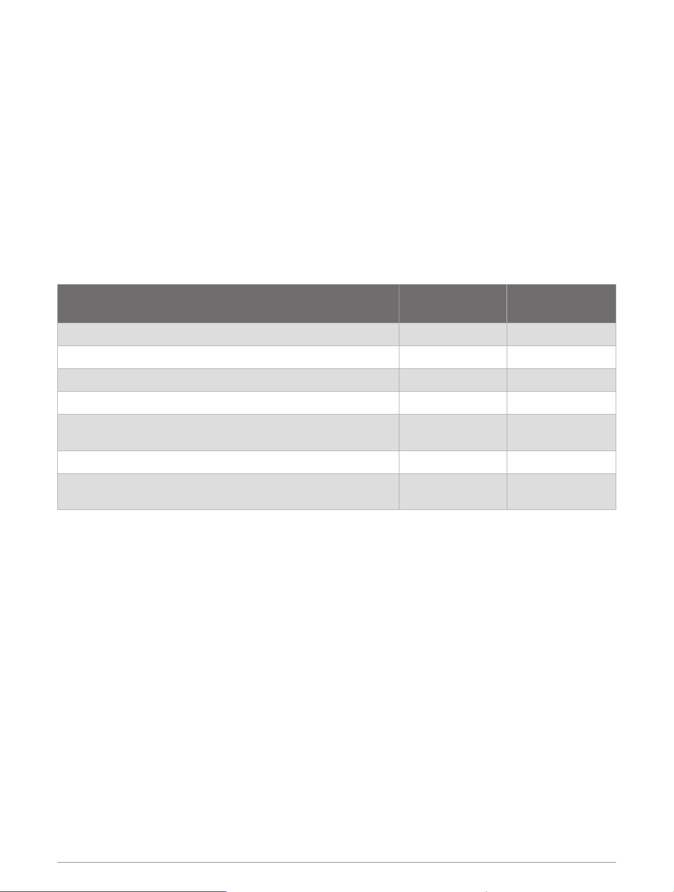
Appendix
ActiveCaptain and Garmin Express
The ActiveCaptain and Garmin Express apps help you manage your Garmin chartplotter and other devices.
ActiveCaptain: The ActiveCaptain mobile app provides an easy-to-use connection between your compatible
mobile device and your compatible Garmin chartplotter, charts, and the Garmin Quickdraw Contours
Community (ActiveCaptain
®
App, page8). The app provides unlimited access to your cartography and a quick,
mobile way to download new charts using the OneChart
™
feature, provides a link to receive notifications on
your chartplotter, and provides access to the ActiveCaptain Community for feedback on marinas and other
boating points of interest. You can also use the app to plan your trip and sync user data. The app checks your
devices for available updates, and notifies you when an update is available.
Garmin Express: The Garmin Express desktop app allows you to use your computer and a memory card to
download and update Garmin chartplotter software and charts (Garmin Express App, page65). You should
use the Garmin Express app for faster data transfer of larger downloads and updates, and to avoid possible
data charges with some mobile devices.
Function
ActiveCaptain
mobile app
Garmin Express
desktop app
Register your new Garmin Marine device Yes Yes
Update your Garmin chartplotter software Yes Yes
Update your Garmin charts Yes Yes
Download new Garmin charts Yes Yes
Access the Garmin Quickdraw Contours Community to download
and share contours with other users
Yes No
Sync a mobile device with your Garmin chartplotter Yes No
Access the ActiveCaptain Community for feedback on marinas and
boating points of interest
Yes No
Garmin Express App
The Garmin Express desktop app allows you to use your computer and a memory card to download and update
Garmin device software and charts and register your devices. We recommend it for larger downloads and
updates for faster data transfer and to avoid possible data charges with some mobile devices.
Installing the Garmin Express App on a Computer
You can install the Garmin Express app on a Windows
®
or Mac
®
computer.
1 Go to garmin.com/express.
2 Select Download for Windows or Download for Mac.
3 Follow the on-screen instructions.
Appendix 65

Registering Your Device Using the Garmin Express App
NOTE: You should use the ActiveCaptain app and a mobile device to register the device (Getting Started with the
ActiveCaptain App, page9).
Help us better support you by completing our online registration today. Keep the original sales receipt, or a
photocopy, in a safe place.
1 Install the Garmin Express app on your computer (Installing the Garmin Express App on a Computer, page65).
2 Insert a memory card into the chartplotter card slot (Inserting Memory Cards, page4).
3 Wait a few moments.
The chartplotter opens the card management page and creates a file named GarminDevice.xml in the
Garmin folder on the memory card.
4 Remove the memory card from your device.
5 Open the Garmin Express app on your computer.
6 Insert the memory card into your computer.
7 If necessary, select Get Started.
8 If necessary, while the application searches, select Sign In next to Have marine charts or devices? near the
bottom of the screen.
9 Create or sign in to your Garmin account.
10 Follow the on-screen instructions to set up your vessel.
11 Select > Add.
The Garmin Express application searches the memory card for the device information.
12 Select Add Device to register the device.
When registration is complete, the Garmin Express application searches for additional charts and chart
updates for your device.
When you add devices to the chartplotter network, repeat these steps to register the new devices using the
Garmin Express app.
66 Appendix

Updating Your Charts Using the Garmin Express App
As of software version 34.00, this device supports up to a 1TB microSD memory card, formatted to exFAT with
speed class 10 or higher.
Downloading the chart update may take up to a few hours.
You should use a blank memory card for chart updates. The update process erases the content on the card and
reformats the card.
1 Install the Garmin Express app on your computer (Installing the Garmin Express App on a Computer, page65).
2 Open the Garmin Express app on your computer.
3 Select your vessel and device.
4 If chart updates are available, select Chart Updates > Continue.
5 Read and agree to the terms.
6 Insert your chartplotter chart memory card into the computer.
7 Select the drive for the memory card.
8 Review the reformat warning, and select OK.
9 Wait while the chart update is copied to the memory card.
NOTE: Copying the update file onto the card may take from a few minutes up to a few hours.
10 Close the Garmin Express app.
11 Eject the memory card from the computer.
12 Turn on the chartplotter.
13 After the home screen appears, insert the memory card into the card slot.
NOTE: In order for the update instructions to appear, the device must be fully booted before the card is
inserted.
14 Select Update Software > Yes.
15 Wait several minutes while the update process completes.
16 When prompted, leave the memory card in place, and restart the chartplotter.
17 Remove the memory card.
NOTE: If the memory card is removed before the device restarts fully, the update is not complete.
Software Updates
You may need to update the software when you install a new device or add an accessory.
You can use the ActiveCaptain mobile app to update the device software (Updating Software with the
ActiveCaptain App, page9).
You can also use the Garmin Express desktop app to update your chartplotter software (Loading the New
Software on a Memory Card Using Garmin Express, page68).
As of software version 34.00, this device supports up to a 1TB microSD memory card, formatted to exFAT with
speed class 10 or higher.
Before you update the software, you should check the software version installed on your device (Viewing System
Software Information, page55). Then, you can go to garmin.com/support/software/marine.html, select See
All Devices in this Bundle, and compare the installed software version to the software version listed for your
product.
If the software version installed on your device is older than the version listed on the website, you should update
the software using the ActiveCaptain mobile app (Updating Software with the ActiveCaptain App, page9) or the
Garmin Express desktop app (Loading the New Software on a Memory Card Using Garmin Express, page68).
Appendix 67

Loading the New Software on a Memory Card Using Garmin Express
You can copy the software update to a memory card using a computer with the Garmin Express app.
As of software version 34.00, this device supports up to a 1TB microSD memory card, formatted to exFAT with
speed class 10 or higher.
Downloading the software update may take from a few minutes up to a few hours.
You should use a blank memory card for software updates. The update process erases the content on the card
and reformats the card.
1 Insert a memory card into the card slot on the computer.
2 Install the Garmin Express app (Installing the Garmin Express App on a Computer, page65).
3 Select your vessel and device.
4 Select Software Updates > Continue.
5 Read and agree to the terms.
6 Select the drive for the memory card.
7 Review the reformat warning, and select Continue.
8 Wait while the software update is copied to the memory card.
NOTE: Copying the update file onto the card may take from a few minutes up to a few hours.
9 Close the Garmin Express app.
10 Eject the memory card from the computer.
After loading the update onto the memory card, install the software on the chartplotter (Updating the Device
Software Using a Memory Card, page68).
Updating the Device Software Using a Memory Card
To update the software using a memory card, you must obtain a software-update memory card or load the
latest software onto a memory card using the Garmin Express app (Loading the New Software on a Memory
Card Using Garmin Express, page68).
1 Turn on the chartplotter.
2 After the home screen appears, insert the memory card into the card slot.
NOTE: In order for the software update instructions to appear, the device must be fully booted before the
card is inserted.
3 Select Install Now > Update Software > Yes.
4 Wait several minutes while the software update process completes.
5 When prompted, leave the memory card in place, and restart the chartplotter.
6 Remove the memory card.
NOTE: If the memory card is removed before the device restarts fully, the software update is not complete.
Cleaning the Screen
NOTICE
Cleaners containing ammonia will harm the anti-reflective coating.
The device is coated with a special anti-reflective coating which is very sensitive to waxes and abrasive
cleaners.
1 Apply an eyeglass lens cleaner specified as safe for anti-reflective coatings to the cloth.
2 Gently wipe the screen with a soft, clean, lint-free cloth.
68 Appendix

Viewing Images on a Memory card
You can view images that are saved on a memory card. You can view .jpg, .png, and .bmp files.
1 Insert a memory card with image files into the card slot.
2 Select > Image Viewer.
3 Select the folder containing the images.
4 Wait a few seconds for the thumbnail images to load.
5 Select an image.
6 Use the arrows to scroll through the images.
7 If necessary, select MENU > Start Slideshow.
Screenshots
You can capture a screenshot of any screen shown on your chartplotter as a .png file. You can transfer the
screenshot to your computer.
Capturing Screenshots
1 Insert a memory card into the card slot.
2 Go to a screen you want to capture.
3 Hold HOME for at least six seconds.
A message appears to confirm the screenshot was captured, including the name of the file written to the
memory card.
Copying Screenshots to a Computer
1 Remove the memory card from the chartplotter, and insert it into a card reader that is attached to a
computer.
2 From Windows Explorer, open the Garmin\scrn folder on the memory card.
3 Copy the image file from the card and paste it to any location on the computer.
Troubleshooting
My device will not acquire GPS signals
If the device is not acquiring satellite signals, there could be a few causes. If the device has moved a large
distance since the last time it has acquired satellites or has been turned off for longer than a few weeks or
months, the device may not be able to acquire the satellites correctly.
• Ensure the device is using the latest software. If not, update the device software (Software Updates, page67).
• Make sure the device has a clear view of the sky so the antenna can receive the GPS signal. If it is mounted
inside of a cabin, it should be close to a window so it can receive the GPS signal.
Appendix 69

My device will not turn on or keeps turning off
Devices erratically turning off or not turning on could indicate an issue with the power supplied to the device.
Check these items to attempt to troubleshoot the cause of the power issue.
• Make sure the power source is generating power.
You can check this several ways. For example, you can check whether other devices powered by the source
are functioning.
• Check the fuse in the power cable.
The fuse should be located in a holder that is part of the red wire of the power cable. Check that the proper
size fuse is installed. Refer to the label on the cable or the installation instructions for the exact fuse size
needed. Check the fuse to make sure there is still a connection inside of the fuse. You can test the fuse using
a multimeter. If the fuse is good, the multimeter reads 0ohm.
• Check to make sure the device is receiving at least 12Vdc.
To check the voltage, measure the female power and ground sockets of the power cable for DC voltage. If the
voltage is less than 12Vdc, the device will not turn on.
• If the device is receiving enough power but does not turn on, contact Garmin product support.
My device is not creating waypoints in the correct location
You can manually enter a waypoint location to transfer and share data from one device to the next. If you have
manually entered a waypoint using coordinates, and the location of the point does not appear where the point
should be, the map datum and position format of the device may not match the map datum and position format
originally used to mark the waypoint.
Position format is the way in which the GPS receiver's position appears on the screen. This is commonly
displayed as latitude/longitude in degrees and minutes, with options for degrees, minutes and second, degrees
only, or one of several grid formats.
Map datum is a math model which depicts a part of the surface of the earth. Latitude and longitude lines on a
paper map are referenced to a specific map datum.
1 Find out which map datum and position format was used when the original waypoint was created.
If the original waypoint was taken from a map, there should be a legend on the map that lists the map datum
and position format used to create that map. Most often this is found near the map key.
2 Select > Preferences > Units.
3 Select the correct map datum and position format settings.
4 Create the waypoint again.
70 Appendix
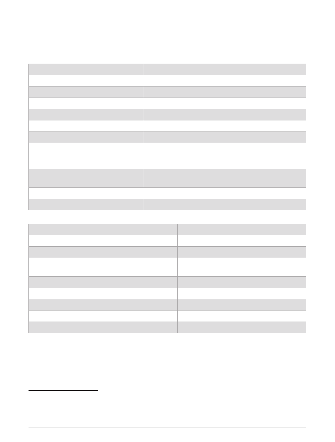
Specifications
Specifications
All Models
Material Polycarbonate plastic
Water rating IEC60529IPX7
3
Temperature range From -15° to 55°C (from 5° to 131°F)
Input voltage From 9 to 18Vdc
Fuse 3A, 125V fast-acting
Memory card 1 microSD card slot; 1TB max. card size
4
Display resolution WVGA , 800 x 480 pixels
Sonar frequencies
5
Traditional: 50/200, 77/200, 83/200kHz
Single Channel CHIRP: from 40 to 250kHz
Garmin ClearVü CHIRP: 260/455/800kHz
Sonar transmit power (RMS)
6
CHIRP: 500W
Garmin ClearVü CHIRP: 500W
Sonar depth
7
701m (2,300 ft.) at 77kHz
Wireless frequency 2.4GHz @ 19.7dBm maximum
5x Models
Dimensions, chartplotter only (W x H x D) 188 x 122 x 61.5mm (7
3
/
8
x4
13
/
16
x2
7
/
16
in.)
Dimensions, on bail mount with sun cover (W x H x D) 212x143.3x100mm (8
3
/
8
x5
5
/
8
x3
15
/
16
in.)
Clearance to nearest obstruction behind chartplotter 57mm (2
1
/
4
in.)
Display size (W x H)
109x65.8mm (4
5
/
16
x2
9
/
16
in.)
127.3mm (5in.)diagonal
Weight 0.5kg (1.1lb.)
Max. power draw 8.4W
Typical current draw at 12Vdc (RMS) 600mA
Max. current draw at 12Vdc 700mA
Compass-safe distance 7.62cm (3in.)
3
The device withstands incidental exposure to water of up to 1m for up to 30min. For more information, go to www.garmin.com/waterrating.
4
As of software version 34.00, this device is compatible with up to1TB memory cards formatted to exFAT.
5
Dependent upon the transducer.
6
Dependent upon the transducer rating and depth.
7
Dependent upon the transducer, water salinity, bottom type, and other water conditions.
Appendix 71
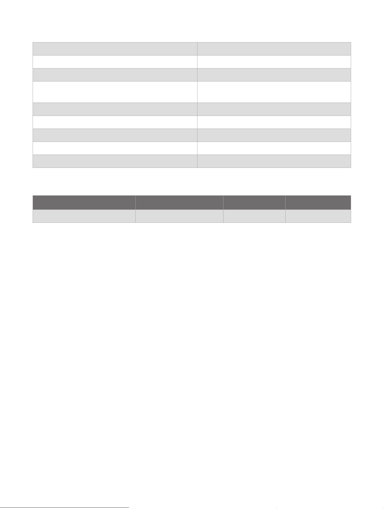
7x Models
Dimensions, chartplotter only (W x H x D) 232x143.1x67mm (9
1
/
8
x5
5
/
8
x2
5
/
8
in.)
Dimensions, on bail mount with sun cover (W x H x D) 243.4x153.9x105.5mm (9
9
/
16
x6
1
/
16
x4
1
/
8
in.)
Clearance to nearest obstruction behind chartplotter 62.5mm (2
7
/
16
in.)
Display size (W x H)
86.9x155.1mm (3
7
/
16
x6
1
/
8
in.)
177.8mm(7in.) diagonal
Weight 0.68kg (1.5lb.)
Max. power draw 15W
Typical current draw at 12Vdc (RMS) 1.1A
Max. current draw at 12Vdc 1.25A
Compass-safe distance 12.7cm (5in.)
Recommended Startup Image Dimensions
For the best fit for the startup images, use an image that has the following dimensions, in pixels.
Model Display resolution Image width Image height
ECHOMAP 5X and 7X WVGA 680 200


support.garmin.com
GUID-CDD85099-F5B6-41B4-84D1-524AE6475690 v9June 2025