
WELDING CUTTING TORCH KIT VICTOR TYPE
ITEM: 55147
OWNER’S MANUAL AND SAFETY INSTRUCTIONS
SAVE THIS MANUAL: KEEP THIS MANUAL FOR SAFETY WARNINGS, PRECAUTIONS, ASSEMBLY,
OPERATING, INSPECTION, MAINTENANCE AND CLEANING PROCEDURES. WRITE THE PRODUCT’S
SERIAL NUMBER ON THE BACK OF THE MANUAL NEAR THE ASSEMBLY DIAGRAM (OR MONTH
AND YEAR OF PURCHASE OF PRODUCT HAS NO NUMBER).
FOR QUESTIONS PLEASE CALL OUR CUSTOMER SUPPORT: (909) 628 4900 MON-FRI 9AM TO 3PM PST

IMPORTANT SAFETY INFORMATION
GENERAL SAFETY WARNINGS
Read all safety warnings and instructions. Failure to follow the warnings and instructions
PD\UHVXOWLQHOHFWULFVKRFN¿UHDQGRUVHULRXVLQMXU\6DYHDOOZDUQLQJVDQGLQVWUXFWLRQVIRU
future reference.
SAFETY
The warnings, precautions, and instructions discussed in this instruction manual cannot cover
all possible conditions and situations that may occur. It must be understood by the operator that
common sense and caution are factors which cannot be built into this product, but must be supplied
by the operator. Read carefully and understand all ASSEMBLY AND OPERATION INSTRUCTIONS
before operating. Failure to follow the safety rules and other basic safety precautions may result in
serious personal injury.
Stay alert, watch what you are doing, and use common sense when operating the tool. DO NOT use the
WRROZKLOH\RXDUHWLUHGRUXQGHUWKHLQÀXHQFHRIGUXJVDOFRKRORUPHGLFDWLRQ
Dress properly. DO NOT wear loose clothing, dangling objects, or jewellery. Keep your hair, clothing
and gloves away from moving parts. Loose clothes, jewellery, or long hair can be caught in moving parts.
:HDUWKHSURSHUSHUVRQDOSURWHFWLYHHTXLSPHQWZKHQQHFHVVDU\Use ANSI Z87.1 compliant safety
goggles (not safety glasses) with side shields, or when needed, a face shield. Use a dust mask in dusty
work conditions.
'2127RYHUUHDFKKeep proper footing and balance at all times.
1
Read and understand all instructions. Failure to follow all instructions may result in serious injury
or property damage.
DO NOT allow persons to operate or assemble the product until they have read this manual and
have developed a thorough understanding of how it works.
DO NOT modify this product in any way. 8QDXWKRUL]HGPRGL¿FDWLRQPD\LPSDLUWKHIXQFWLRQDQGRU
VDIHW\DQGFRXOGDIIHFWWKHOLIHRIWKHSURGXFW7KHUHDUHVSHFL¿FDSSOLFDWLRQVIRUZKLFKWKHSURGXFW
was designed.
Inspect the work area before each use. Keep work area clean, dry, free of clutter, and well-lit.
&OXWWHUHGZHWRUGDUNZRUNDUHDVFDQUHVXOWLQLQMXU\8VLQJWKHSURGXFWLQFRQ¿QHGZRUNDUHDV
may put you dangerously close to cutting tools and rotating parts.
'2 127 XVH WKH SURGXFW ZKHUH WKHUH LV D ULVN RI FDXVLQJ D ¿UH RU DQ H[SORVLRQ; e.g., in the
SUHVHQFHRIÀDPPDEOHOLTXLGVJDVHVRUGXVW7KHSURGXFWFDQFUHDWHVSDUNVZKLFKPD\LJQLWHWKH
ÀDPPDEOHOLTXLGVJDVHVRUGXVW
DO NOT allow the product to come into contact with an electrical source. The tool is not insulated
and contact will cause electrical shock.
Keep children and bystanders away from the work area while operating the tool. DO NOT allow
children to handle the product.
Be aware of all power lines, electrical circuits, water pipes, and other mechanical hazards in
your work area. Some of these hazards may be hidden from your view and may cause personal injury
DQGRUSURSHUW\GDPDJHLIFRQWDFWHG
Remove keys or wrenches before connecting the tool to an air supply, power supply, or turning on
the tool. A wrench or key that is left attached to a rotating part of the tool may cause personal injury.
2
Check for damaged parts before each use. Carefully check that the product will operate properly and
perform its intended function. Replace damaged or worn parts immediately. Never operate the
product with a damaged part.
DO NOT use a product with a malfunctioning switch. Any power tool that cannot be controlled with
the power switch is dangerous and must be repaired by an authorized service representative
before using.
Disconnect the power/air supply from the product and place the switch in the locked or off position
before making any adjustments, changing accessories, or storing the tool. Such preventive safety
measures reduce the risk of starting the tool accidentally.
IMPORTANT SAFETY INFORMATION
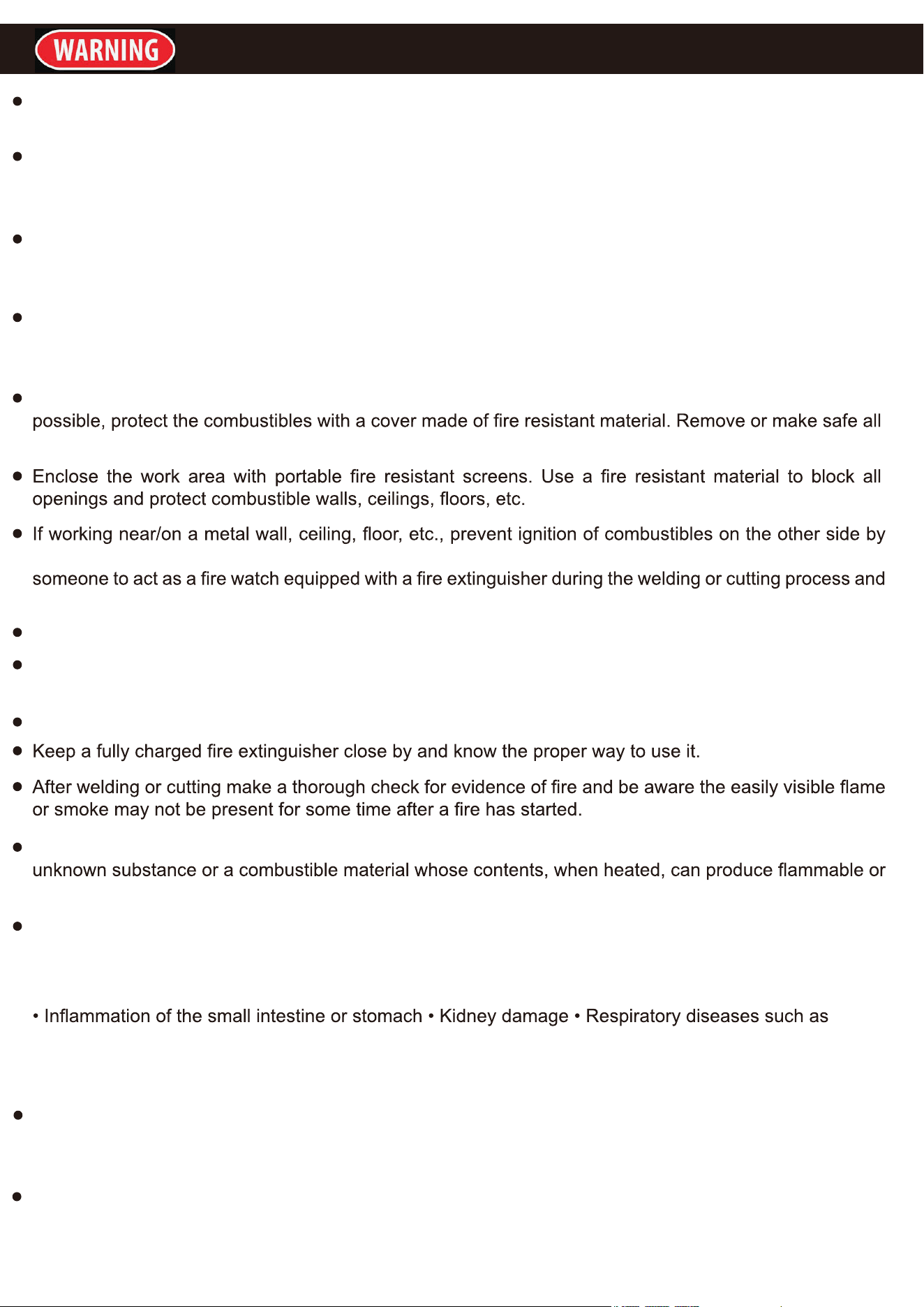
When possible, move the work to a location well away from combustible materials. If relocation is NOT
combustible materials for a radius of 35 feet (10 meters) around the work area.
moving the combustibles to a safe location. If relocation of combustibles is NOT possible, designate
for at least one half hour after the welding or cutting project is completed.
DO NOT place the Torch on any material other than bare concrete until it has cooled completely.
DO NOT weld or cut any material that has a combustible coating or a combustible internal structure, such
as drums or tanks, without an approved method for eliminating the hazard.
DO NOT dispose of hot slag in containers holding combustible materials.
Clean and purge containers before applying heat. DO NOT apply heat to a container that has held an
explosive vapors. Vent closed containers, including castings, before preheating, cutting, or welding.
INHALATION HAZARD: Welding and Cutting Produce TOXIC FUMES. Exposure to welding or cutting
exhaust fumes can increase the risk of developing certain cancers, such as cancer of the larynx and lung
cancer. Also, some diseases that may be linked to exposure to welding or cutting exhaust fumes are: •
Early onset of Parkinson’s Disease • Heart disease • Ulcers • Damage to the reproductive organs
emphysema, bronchitis, or pneumonia Use natural or forced air ventilation and wear a respirator approved
by NIOSH to protect against the fumes produced to reduce the risk of developing the
above illnesses.
WARNING: This product, when used for welding, plasma cutting, soldering, or similar applications,
produces chemicals known to the State of California to cause cancer and birth defects or other reproductive
harm. (California Health & Safety Code § 25249.5, et seq.)
WARNING: The brass components of this product contain lead, a chemical known to the State of
California to cause cancer and birth defects or other reproductive harm. (California Health & Safety Code
§ 25249.5, et seq.)
3
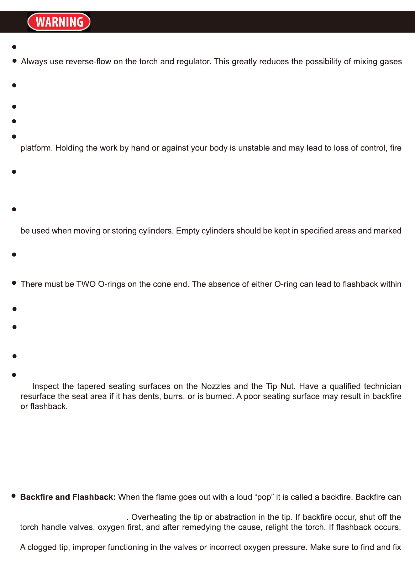
Make sure you are prepared to begin work before opening gas supply.
in the regulator or hose.
Use with oxygen and acetylene only. DO NOT
modify this torch or use it for a purpose for which it is not
intended.
Set Acetylene Regulator no greater than 15 PSI. Acetylene is unstable and can explode if over-pressurized.
DO NOT use oil, grease or thread seal tape on any connector.
Use clamps (not included) or other practical ways to secure and support the work piece to a stable
and/or personal injury.
Use only accessories that are recommended by the manufacturer for your model Torch. Accessories that
may be suitable for one Torch may become hazardous when used on another Torch. Only use proper
gas hoses.
Proper cylinder care. Secure cylinders to a cart, wall or post to prevent them from falling. All cylinders
should be used and stored in an upright position. Never drop or strike a cylinder. Cylinder caps should
“empty”
Never use oil or grease on any inlet connector, outlet connector or cylinder valves. Keep regulators free
of gas and oil.
the torch handle or cutting attachment.
DO NOT store cylinders in temperatures 120° F or higher.
KEEP WRENCH ON ACETYLENE CYLINDER’S VALVE whenever cylinder is in use to allow quick shut
off in case of emergency.
DO NOT USE FLAME TO DETECT LEAKS.
INSPECT BEFORE EVERY USE. Look for the following, and do not use kit if any damage is noted:
A.
B. Examine all hoses for cuts, cracks, burns, worn areas, or other damage. DO NOT use if damaged.
C. Check for loose connections using soapy water solution. Tighten or repair any leaks found.
D. DO NOT use the Torch Kit if either gas does not turn off completely when the Oxygen Torch Valve and
Acetylene Torch Valve are closed. Leakage of gas from the tip is a substantial safety risk. If gas cannot
be turned off at the Torch Handle, it is dangerous and must be replaced.
E. Inspect for any other defects or damage. Do not use any damaged parts. Tag damaged parts “Do not
use” until repaired.
be caused by A. Operating the torch at low pressures required for the toll tips used. B. Touching the
tip against the work piece. C
close the torch handle valves immediately. Flashback generally indicates a problem that needs repaired.
the cause before lighting the torch.
IMPORTANT SAFETY INFORMATION
4
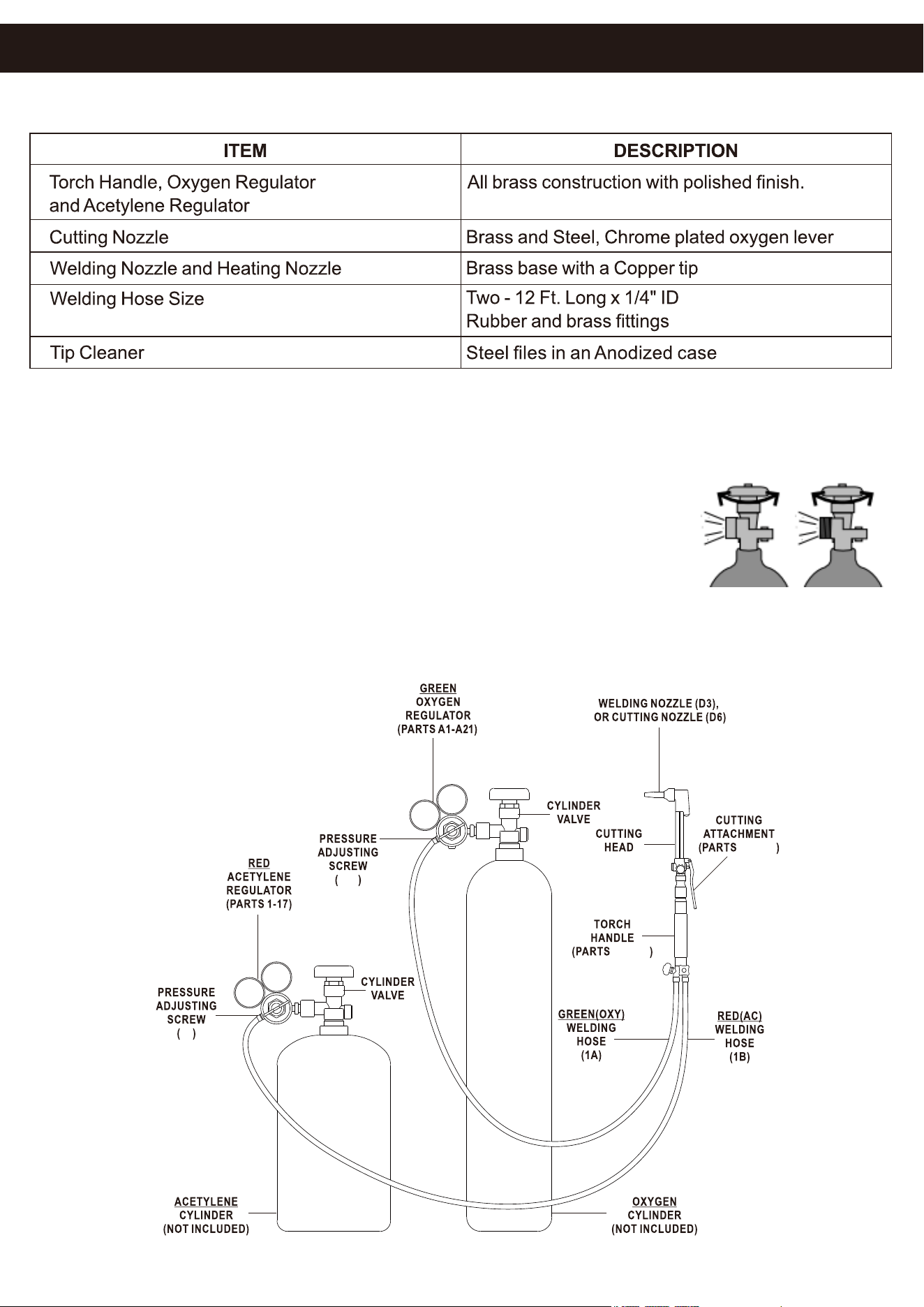
PRODUCT SPECIFICATIONS
ASSEMBLY AND OPERATING PROCEDURES
NOTE: The following instructions are for acetylene gas use only. DO NOT use other fuel gases.
1. While standing on one side, “crack” each cylinder valve. “Cracking” is to
quickly open and close the valve, allowing gas to escape and clearing the
valve of any foreign material. If any oil or grease is found do not use the
cylinder and contact the supplier immediately.
2. Attach the GREEN oxygen regulator (Parts A1-A21)) to the oxygen cylinder. Then, attach the RED
acetylene regulator (parts 1-17) to the acetylene cylinder. Make sure they are tightened in the correct
directions (normally clockwise for oxygen and counter-clockwise for acetylene) DO NOT USE THREAD
SEALING TAPE.
16
A16
C1-C29
B1-B11
ASSEMBLY AND OPERATING INSTRUCTIONS
5
3. IMPORTANT: The pressure adjusting screw (16) on the acetylene regulator and the pressure adjusting
screw (A16) on the oxygen regulator should be turned counter-clockwise to relieve pressure on the
regulator diaphragms before opening the cylinder valves. If this is not done, pressure form the cylinders
may damage the diaphragms and render the regulators inoperable.
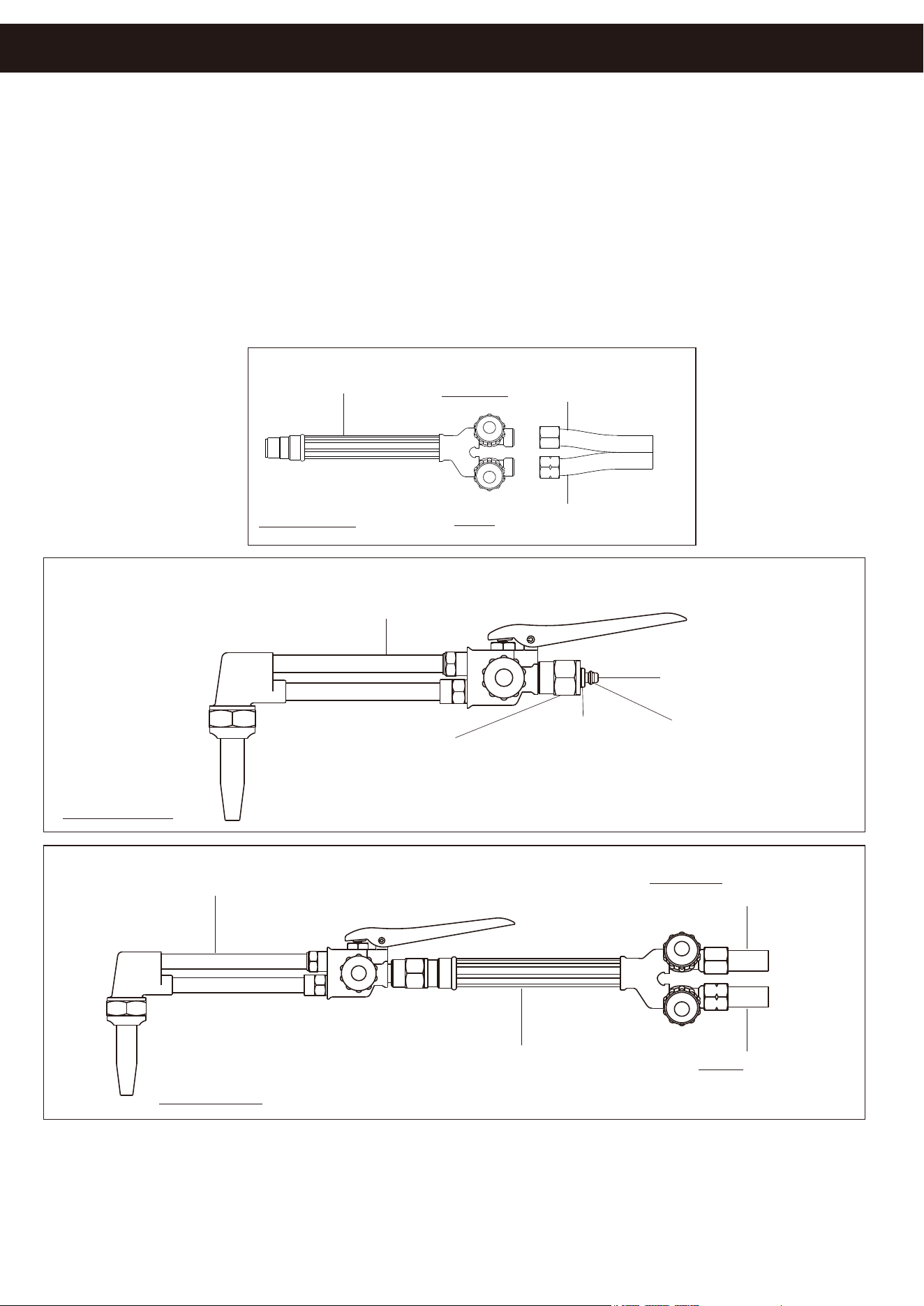
4. Connect the GREEN and RED
welding hoses (1A and 1B) to the proper connections on the torch handle
(parts B1-B11)
5. Connect the cutting attachment (C1-C29) to the torch handle (B1-B11) Always check the cone end
(C23) and coupling nut (C22) for damage or oil. If either are found, discontinue use and contact your gas
supplier.
6. Check connections for leaks. Adjust the acetylene regulator (parts 1-17) and oxygen regulator (parts
A1-A21) to their normal operating pressure. Use an approved leak detection solution to check for leaks
at the welding hoses (A1 and 1B) and cylinder valve connections. If leaks are fond, tighten nuts more
securely.
IF GURE G
CUTTING ATTACHMENT(PARTS C1-C29)
COUPLING NUT(22)
O-RUBG
(C24)
O-RUBG
(C25)
CONE END(C23)
UC TTING ATTACHMENT(PARTS C1-C29)
GREEN (OX)WELDING
HOSE(1A)
RED (ACE)
WELDING HOSE(1B)
TORCH HANDLE(PARTS)
FIGURE H
FIGURE F
TORCH HANDLE
(PARTS B1-B11)
GREEN WELDING HOSE(1A)
RED WELDING HOSE(1B)
ASSEMBLY AND OPERATING INSTRUCTIONS
6
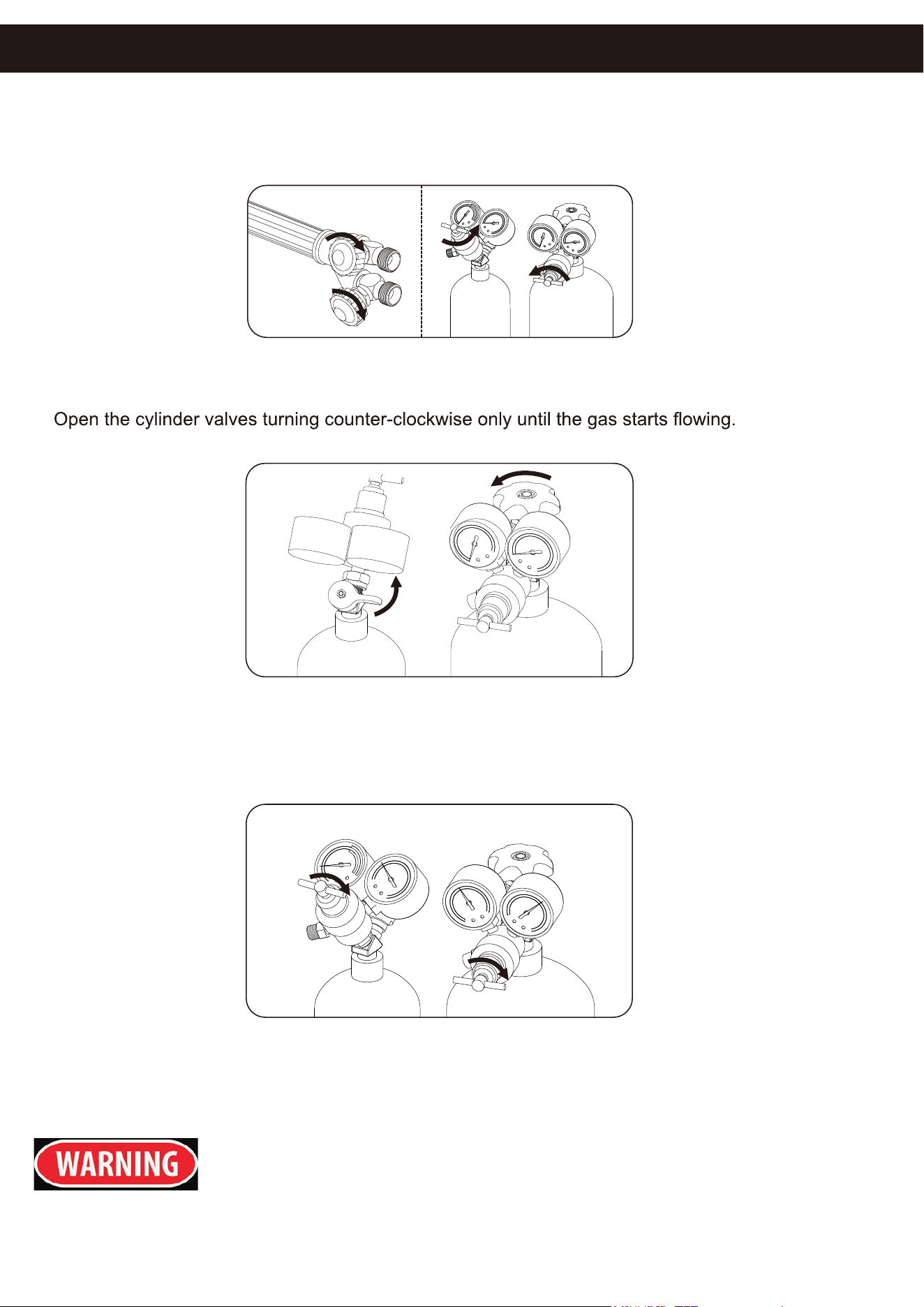
1. After everything is connected, close both Torch Handle Valves, turning clockwise. Close Regulators,
turning knobs counter-clockwise until loose.
2.
WARNING! Only
open Acetylene Cylinder Valve 1/4 to 1/2 turn.
3. Open the Oxygen cylinder valve completely, turning it counter-clockwise.
4. Adjust the Oxygen Regulator to deliver 20 PSI. Adjust the Acetylene Regulator to deliver 10 PSI.
DO NOT EXCEED 15 PSI ACETYLENE PRESSURE.
5. Check all connections for leaks using soapy water: • If leaks are found, tighten connections. • If a leak
persists, discontinue use and call gas supplier. • If no leaks are found with this test, move on to the Gauge
Monitoring test.
DANGER! To prevent serious injury and/or death, DO NOT tighten or adjust
any connection between the cylinder and cylinder valve, or force the cylinder
valve. If the cylinder valve is leaking, move the cylinder outside and notify
your gas supplier immediately.
CHECKING FOR LEAKS
Close Valves
(Turn clockwise)
Close Regulators
(Turn counterclockwise until loose)
Leak Test 1 Step 1
Acetylene
Cylinder
Oxygen
Cylinder
Leak Test 1 Step 2: Open Cylinder Valves
20 PSI
10 PSI
Oxygen
Regulator
Acetylene
Regulator
Leak Test 1 Step 3: Set Testing Pressures
NEVER set the Acetylene Regulator (Parts 1-17) to a delivery
9. To determine the proper acetylene regulator parts (parts 1-17) pressure and oxygen regulator (parts
C1-C29
10. Depending on use, attach either the cutting nozzle (D6) or welding nozzle (D3) to the cutting attachment
11. Open the oxygen control valve (B10 with Ox label) on the torch handle. Open the pre-heat oxygen
valve (C29) on the cutting attachment. Adjust the oxygen regulator parts (A1 - A21) to the desired working
7
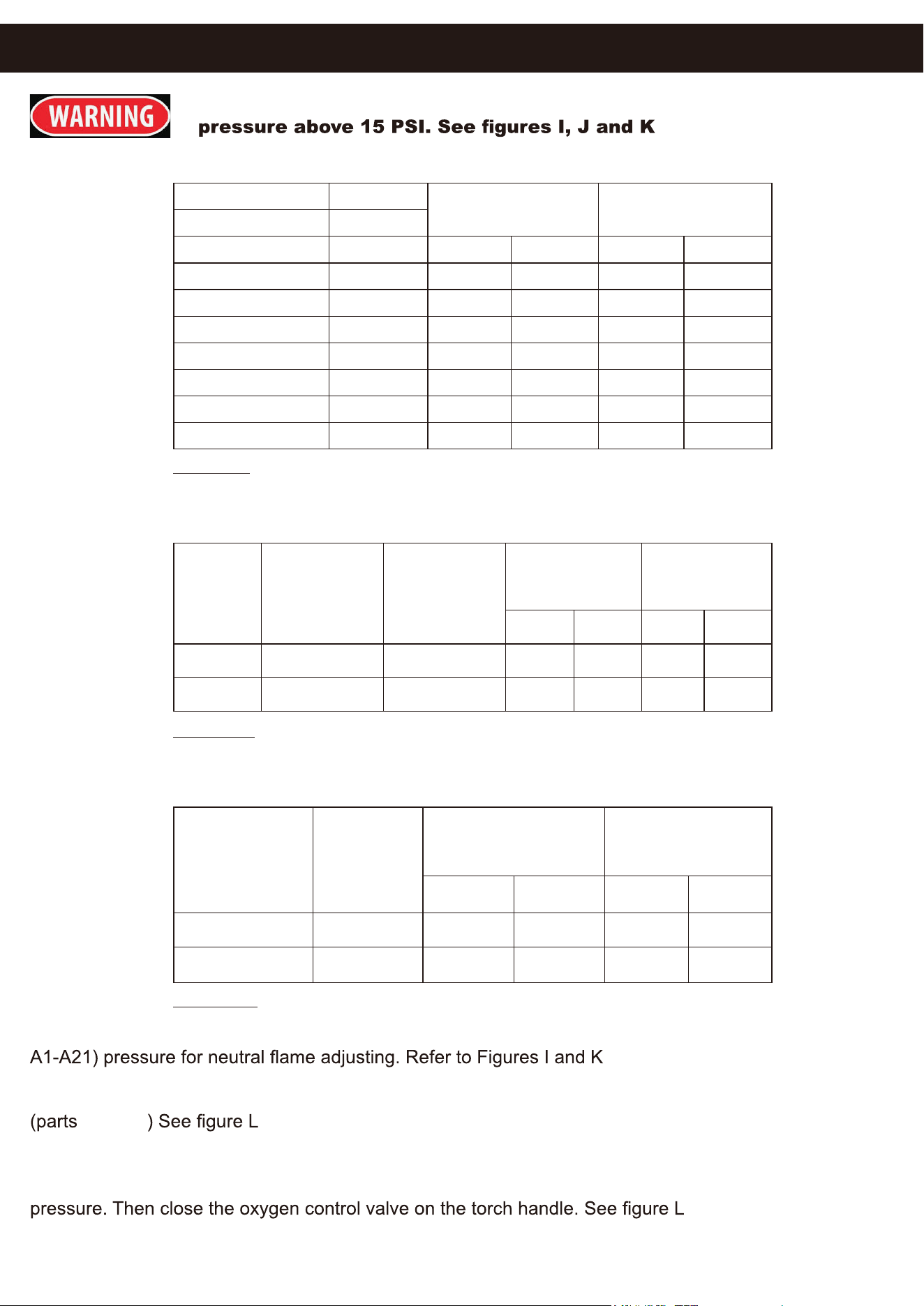
WELDING TIP CHART
Metal Thickness
Oxygen Pressure
P.S.I.G.
Acetylene Pressure
P.S.I.G.
Tip Size
1/64"-3/64"
1/32"-5/64"
3/64"-3/32"
1/16"-1/8"
1/8"-3/16"
3/16"-1/4"
1/4"-1/2"
00
0*
1
2
3
4
5
Min.
3
3
3
3
4
5
6
Max.
5
5
5
5
7
10
12
3
3
3
3
3
4
5
5
5
5
5
6
7
8
OXY-ACETYLENE MULTI-FLAME HEATING CHART
FIGURE I
*Included
Tip Size
6
8
Acetylene
Pressure
Range
P.S.I.G.
4-6
8-12
Oxygen
Pressure
Range
P.S.I.G.
8-11
10-18
14
30
40
80
15
33
44
88
Min. Min.
Max. Max.
Acetylene Cubic
Feet Per Hour
Oxygen Cubic
Feet Per Hour
FIGURE J
OXY-ACETYLENE CUTTING NOZZLE CHART
FIGURE K
*Included
Acetylene
Pressure
P.S.I.G.
Oxygen
Pressure
P.S.I.G.
Metal Thickness
Nozzle Size
Min. Min.
Max.
Max.
1/2"
3/4"
0
1**
30
30
35
35
3
3
5
5
CHARTS
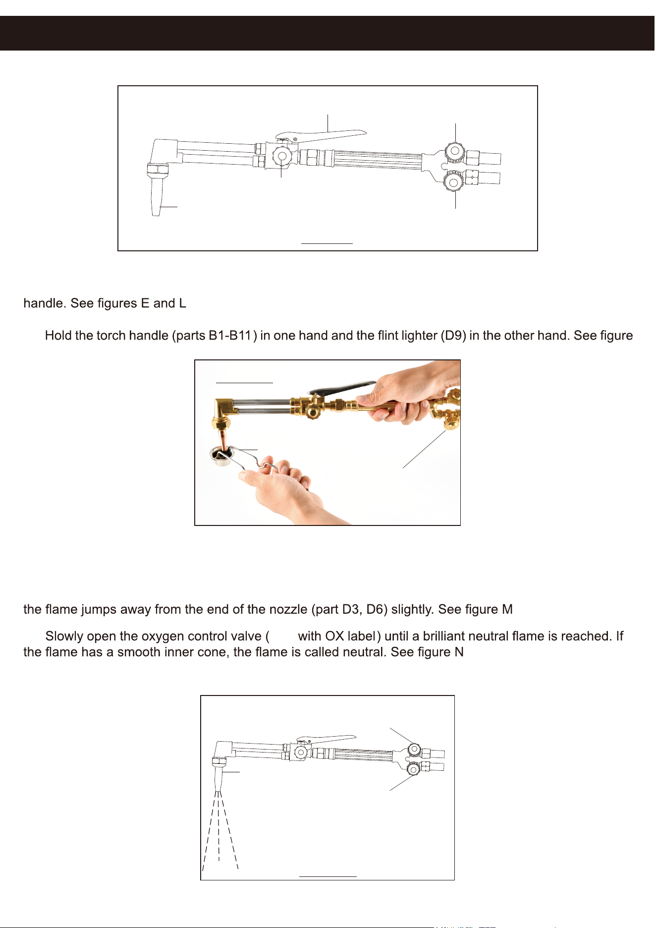
FLINT LIGHTER(D9)
ACETYLENE
CONTROL
VALVE
(B10 w ith AC Label )
FIGURE M
OPERATION
12. Open the acetylene control valve (B10 with AC label on the torch handle. Adjust the acetylene
regulator (parts 1-17) to the desired working pressure. Then close the acetylene control valve on the torch
13.
M.
14. Open the acetylene control valve (B10 and AC label ) about a 1/4 turn and ignite the acetylene gas
coming out of the nozzle (part D3, D6) Always point the nozzle away from other people when lighting.
15. Slowly open the acetylene control valve (B10 and AC label) further until the smoke subsides and
16.
Always use the appropriate welding goggles or welding helmet when welding or
cutting.
8
HIGH PRESSURE LEVER
(C20)
OXYGEN CONTROL VALVE
(B10 with OX Label)
( B10 with AC Label)
ACETYLENE CONTROL VALVE
PRE-HEAT OXYGEN CONTROL VALVE
(C29)
CUTTING NOZZLE
(D6)
FIGURE L
OXYGEN CONTROL VALVE
ACETYLENE
CONTROL VALVE
NOZZLE(PARTS D6)
FIGURE N
B10
( B10 with OX Label)
( B10 with AC Label)
9
17. Once the welding or cutting job is completed, turn off the oxygen control valve (B10 with OX label)
Then turn off the acetylene control valve (B10 with AC label)
MAINTENANCE
NOTE:
18.
19. Drain the gas from the oxygen regulator parts (A1-A21) by opening the oxygen control valve (B10 with
20. Release the pressure on the acetylene and oxygen regulators by turning their pressure adjusting screws
INSPECTION, MAINTENANCE AND CLEANING
Make sure the welding kit is cool to the touch and disconnected from
its oxygen and acetylene cylinders before performing any inspection,
maintenance or cleaning procedures.
1. BEFORE EACH USE, inspect the general condition of the welding kit. Check for loose screws,
misalignment or binding of moving parts, cracked or broken parts, damaged welding hoses and any other
condition that may affect its safe operation. If a problem occurs, have the problem corrected before further
use. DO NOT USE DAMAGED EQUIPMENT.
2. PERIODICALLY, Use the tip cleaner (D7) to clean out dirt and debris from the nozzles (parts D3, D6)
make sure to use the correct size tip cleaner for each individual nozzle. See assembly diagram
3. TO CLEAN, use a cloth. If necessary, a mild detergent may be used. Do not immerse any part of the
welding kit in liquid.
Troubleshooting
Before turning
on Torch, gas
odor is noticed.
1. Hose connections loose.
2. Crack in hose.
3. Cylinder leak at neck.
Problem
Possible Causes
Likely Solutions
1. Tighten all connections.
2. Check hoses. If any cracks are found, replace entire hose.
DO NOT PATCH OR TAPE GAS HOSES.
3. Check neck area of cylinders.
If cracks or damage are found, do not use.
Secure upright, in a well-ventilated area, well away from
sources of ignition. Contact gas supplier IMMEDIATELY.
Replace cylinders before proceeding with work.
Flame is irregular.
1. Cutting tip clogged or dirty.
2. Gas low.
1. Close gas, oxygen ¿UVWthen acetylene.
Let Torch cool completely.
Remove Tip, check for dirt and debris.
Use tip cleaner to clean Tip or replace if necessary.
2. Check gas level and UH¿OOif needed.
16, A16
10
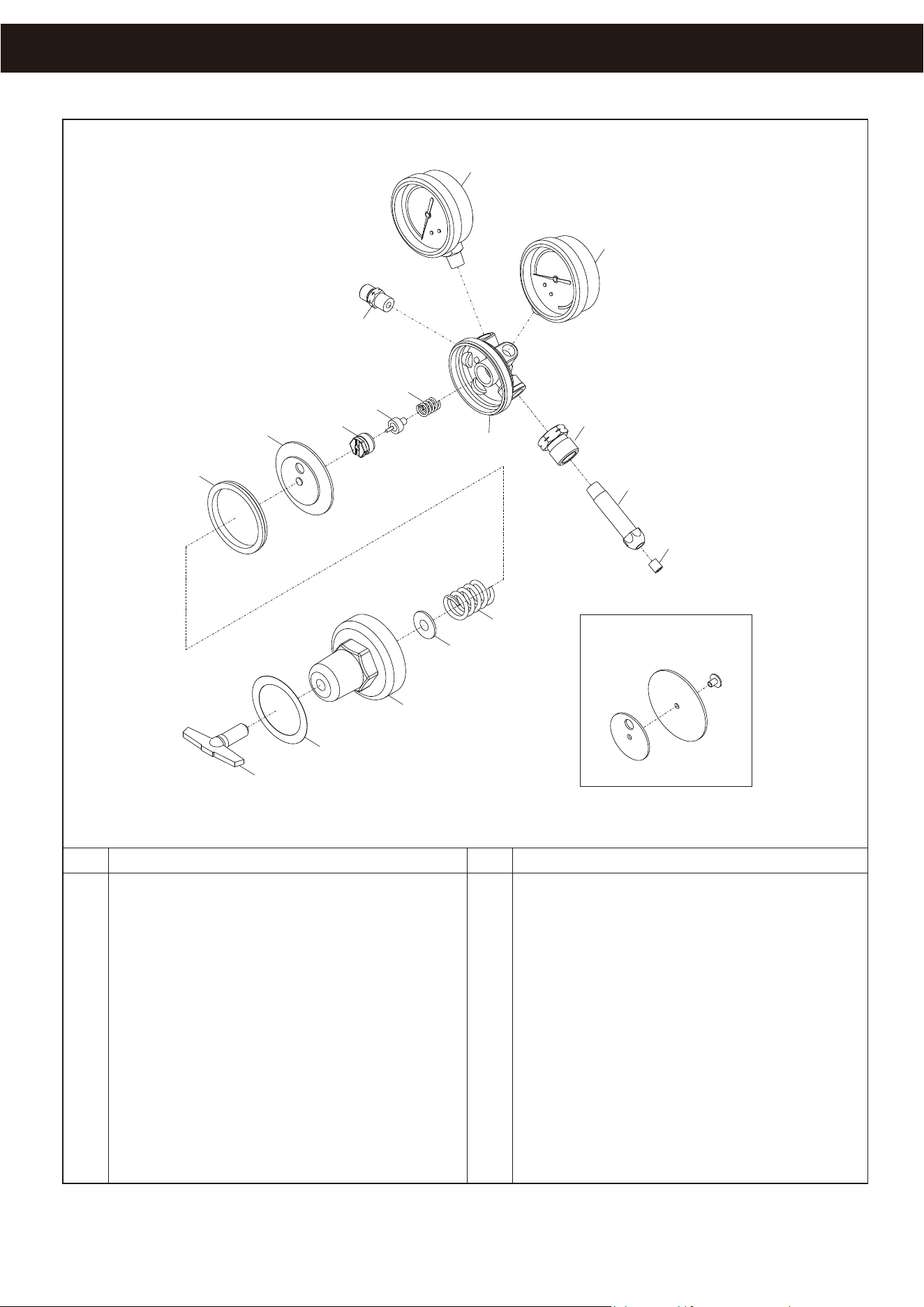
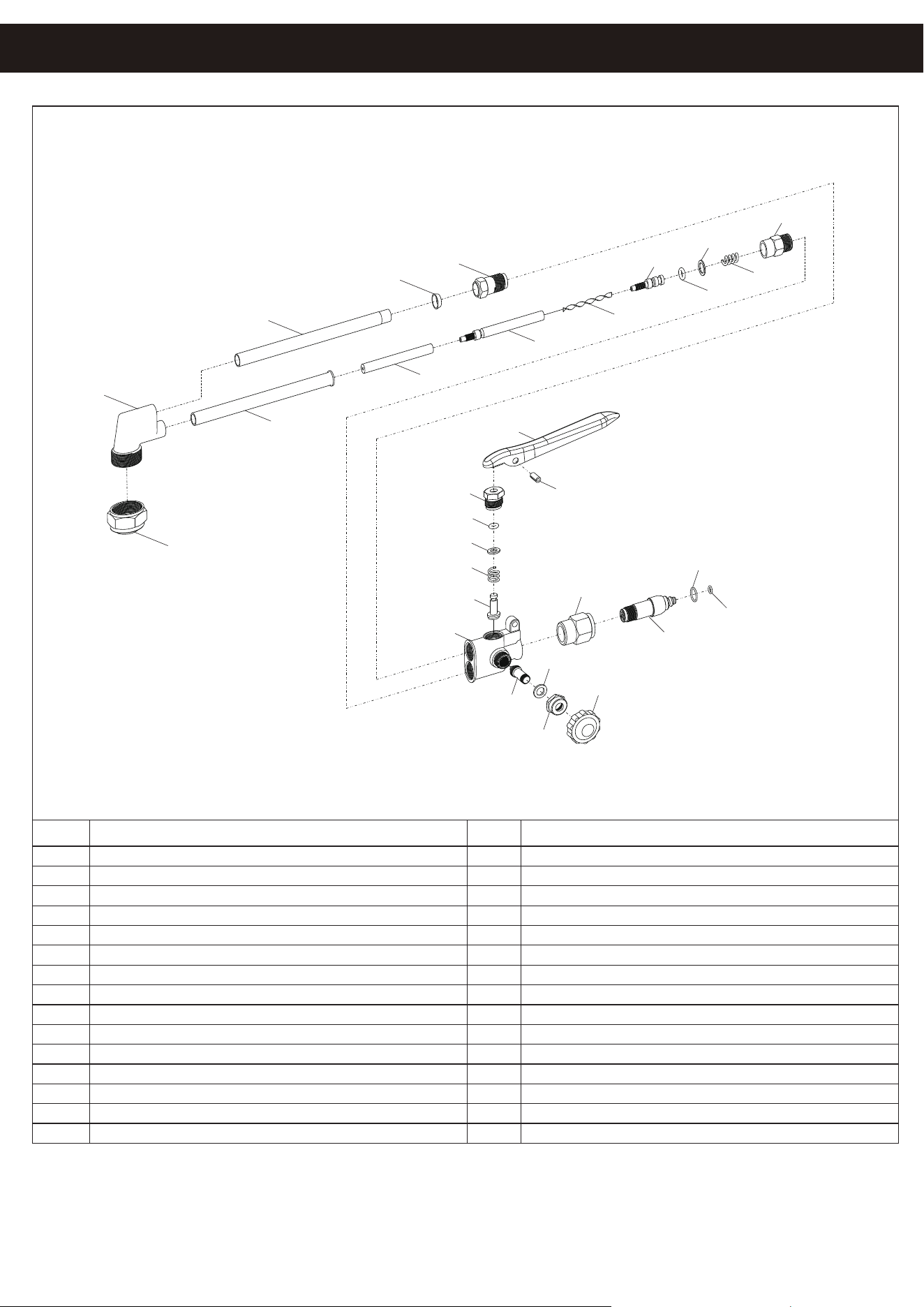
PARTS LIST
NOTE: Some parts are listed and shown for illustrations purposes only and are not available individually
as parts.
NO.
1
2
3
4
5
6
7
8
9
10
10A
10B
10C
Bady
H.P. Gauge
L.P. Gaug
e
Inlet Nut (CGA 510)
Inlet Spigot
Filter
Valve Spring
Valve
Nozzle
Dlaphragm Assembly
Dlaphragm Plate
Diaphragm
Centralizer
D
ACETYLENE REGULATOR PARTS LIST # 1-17
PART NO. # 1-17
ESCRIPTION
NO.
DESCRIPTION
11
12
13
14
15
16
17
Gasket
Adjusting Spring
Spring Button
Bonnet
Label
Adjusting Screw "T"Bar
Outlet Adaptor
16
15
14
13
12
11
10
10A
10B
10C
Detail A
9
8
1
7
17
2
3
4
5
6
PARTS LIST
11
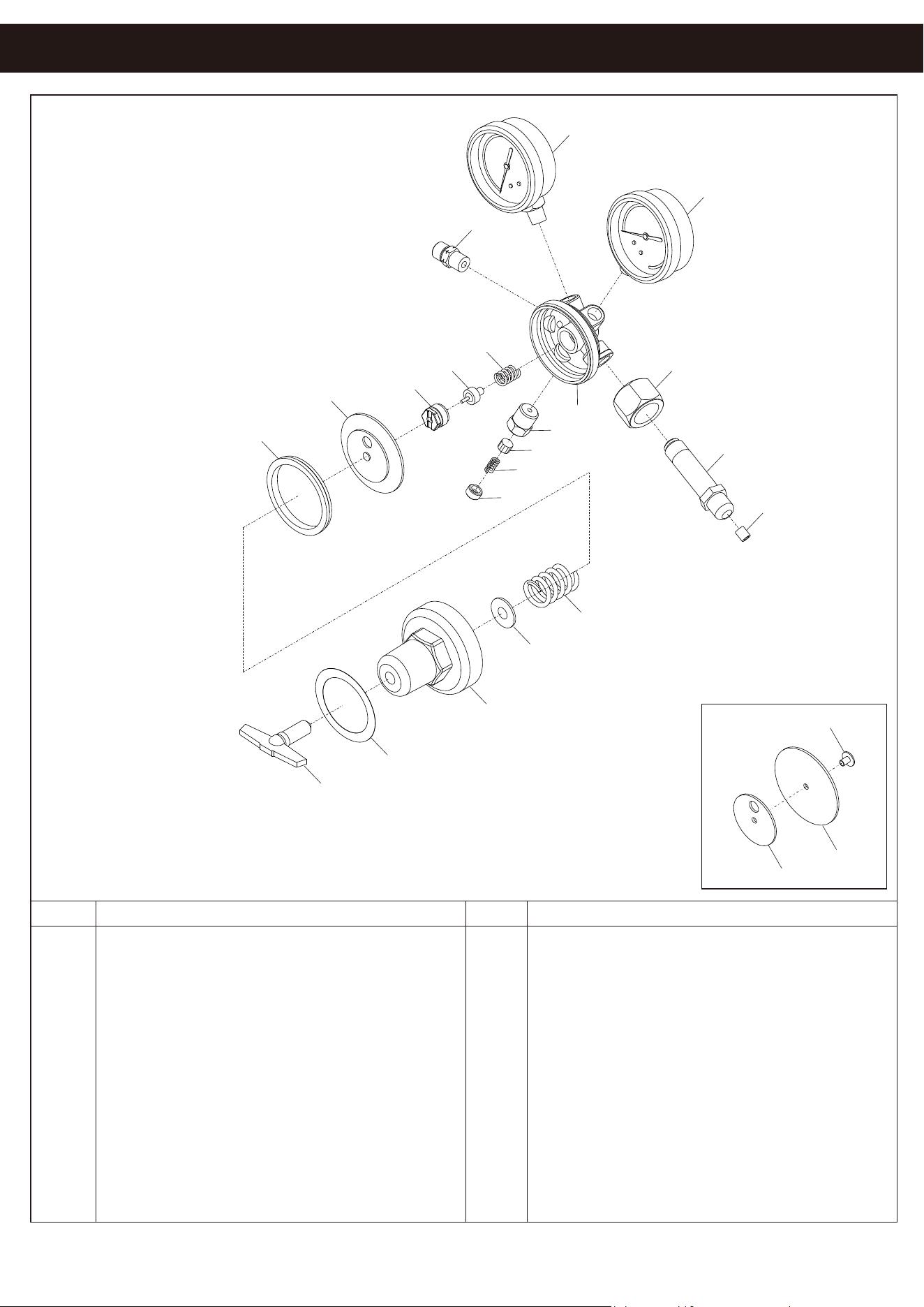
N
O.
A1
A2
A3
A4
A5
A6
A7
A8
A9
A10
A10a
A10b
A10c
Bady
H.P. Gauge
L.P. Gauge
Inlet Nut (CGA 540)
Inlet Spigot
Filter
Valve Spring
Valve
Nozzle
Dlaphragm Assembly
Dlaphragm Plate
Diaphragm
Centralizer
DESCRIPTION
A11
A12
A13
A14
A15
A16
A17
A18
A19
A20
A21
NO.DESCRIPTION
Gasket
Adjusting Spring
Spring Button
Bonnel
Label
Adjusting Screw"T" Bar
Outlet Adaptor
Safety Body
Safety Seat
Safety Spring
Safety Cap
A1
A2
A17
A14
A15
A16
A7
A8
A9
A12
A11
A13
A14
A15
A16
A10
A3
A18
A19
A20
A21
Detail A
A10a
A10b
A10c
OXYGEN REGULATOR PARTS LIST # A1-A21
PART NO. # A1-A21
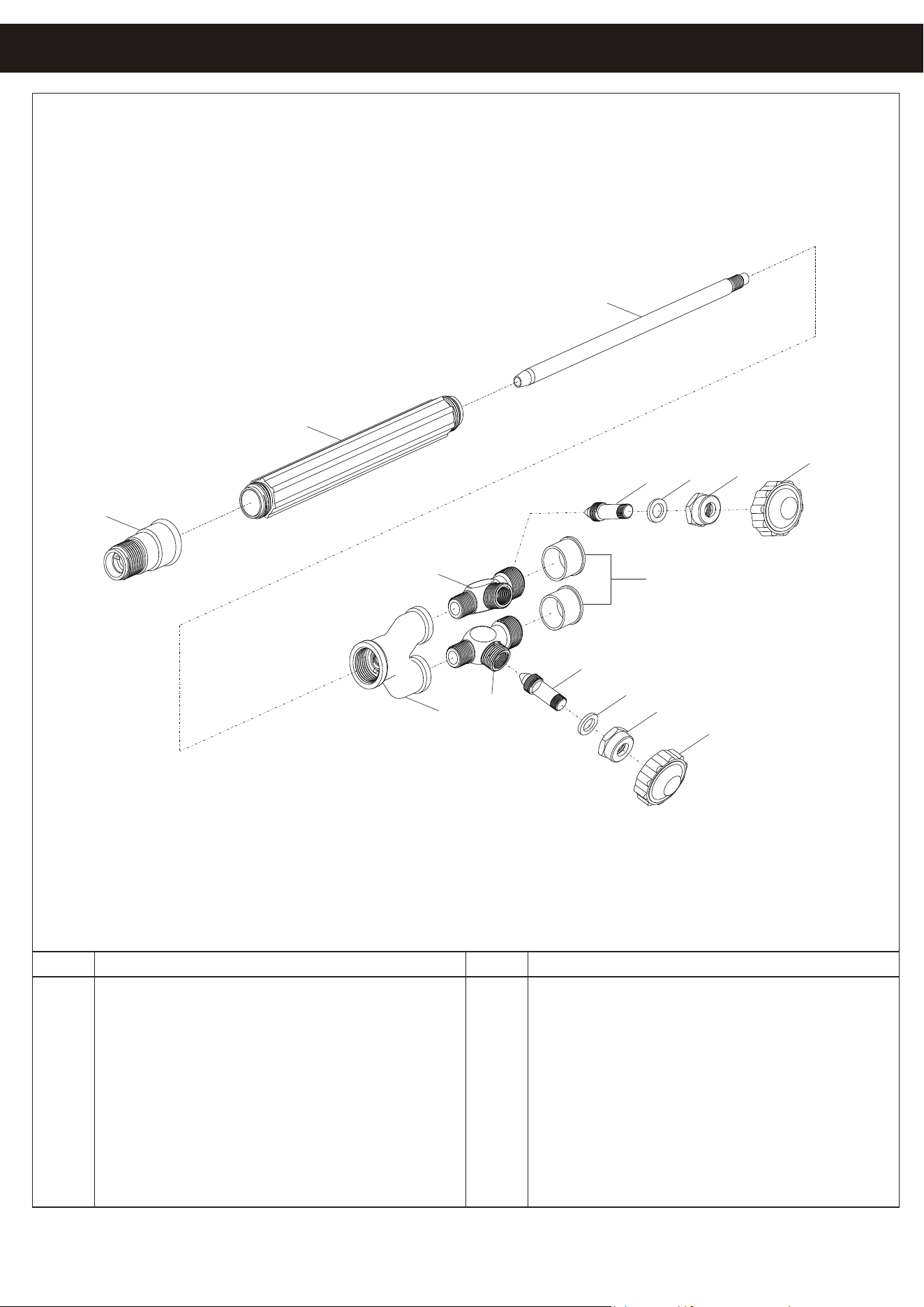
PARTS LIST
12
NOTE: Some parts are listed and shown for illustrations purposes only and are not available individually
as parts.
NO. NO.DESCRIPTION DESCRIPTION
B1
B2
B3
B4
B5
B6
Torch Head
Handle
Inner Tube
Tail
Oxygen Valve Body
Gas Valve Body
B7
B8
B9
B10
B11
Valve Stem
Washer
Nut
Adjusting Knob
Cover
B1
B2
B3
B4
B5
B7
B6
B7
B8
B9
B10
B8
B9
B10
B11
TORCH HANDLE PARTS LIST # B1-B11
PART NO. # B1-B11
PARTS LIST
13
NOTE: Some parts are listed and shown for illustrations purposes only and are not available
individually as parts.
C1
C2
C3
C4
C5
C6
C7
C8
C9
C10
C11
C12
C13
C14
C15
DESCRIPTION DESCRIPTION
C16
C17
C18
C19
C20
C21
C22
C23
C24
C25
C26
C27
C28
C29
Tip Nut
Head
Oxygen Tube
Nut
Ferule
Fuel Tube
Inner Tube (A)
Inner Tube (B)
Spiro
O-Ring
Inner Tube(C)
Washer (TeÀon)
Spring
Nut
Body
Valve
HP Spring
Washer
Valve Cap
Lever
Spiral Pin
Coupling Nut
Cone End
O-Ring (Big)
O-Ring (Small)
Valve Stem
Washer
Nut
Adjusting Knob
NO.NO.
C1
C2
C3
C4
C5
C6
C7
C8
C9
C10
C11
C12
C13
C14
C16
C17
C18
C11
C19
C20
C21
C22
C24
C25
C23
C15
C26
C28
C27
C29
CUTTING ATTACHMENT PARTS LIST # C1-C29
PART NO. # C1-C29
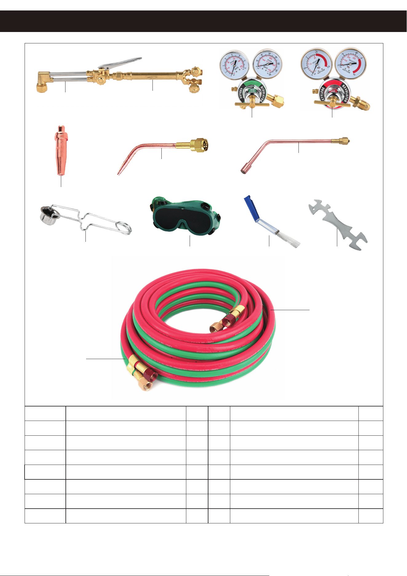
PARTS LIST
14
NOTE: Some parts are listed and shown for illustrations purposes only and are not available
individually as parts.
NO. Description
Qty
NO. Description
Q
ty
C1-C29
B1-B11
A1-A21
1-17
D6
D3
D4
1
1
1
1
1
1
3
1
1
1
1
1
1
D9 Flint Lighter
Cutting Attachment
Torch Handle
Oxygen Regulator
Acetylene Regulator
Cutting Nozzle
Welding Nozzle
Heating Tip
D8
Welding Glasses (Shaded)
D7
D5
1A
1B
Tip Cleaner
Spanner
Green(OX) Welding Hose*
Red(AC) Welding Hose*
D6
D3
D9
D8
D7 D5
1A
1B
C1-C29
B1-B11
A1-A21 1-17
D4
15
THE MANUFACTURER AND/OR DISTRIBUTOR HAS PROVIDED THE PARTS LIST AND ASSEMBLY
DIAGRAM IN THIS MANUAL AS A REFERENCE TOOL ONLY. NEITHER THE MANUFACTURER OR
DISTRIBUTOR MAKES ANY REPRESENTATION OR WARRANTY OF ANY KIND TO THE BUYER THAT
HE OR SHE IS QUALIFIED TO MAKE ANY REPAIRS TO THE PRODUCT, OR THAT HE OR SHE IS
QUALIFIED TO REPLACE ANY PARTS OF THE PRODUCT. IN FACT, THE MANUFACTURER AND/OR
DISTRIBUTOR EXPRESSLY STATES THAT ALL REPAIRS AND PARTS REPLACEMENTS SHOULD BE
UNDERTAKEN BY CERTIFIED AND LICENSED TECHNICIANS, AND NOT BY THE BUYER. THE BUYER
ASSUMES ALL RISK AND LIABILITY ARISING OUT OF HIS OR HER REPAIRS TO THE ORIGINAL
PRODUCT OR REPLACEMENT PARTS THERETO, OR ARISING OUT OF HIS OR HER INSTALLATION
OF REPLACEMENT PARTS THERETO.
Record Product’s Serial Number Here:
Note: If product has no serial number, record month and year of purchase instead.
Note: Some parts are listed and shown for illustration purposes only and are not available individually
as replacement parts.
PLEASE READ THE FOLLOWING CAREFULLY
DISCLAIMER