USER AND INSTALLATION MANUAL
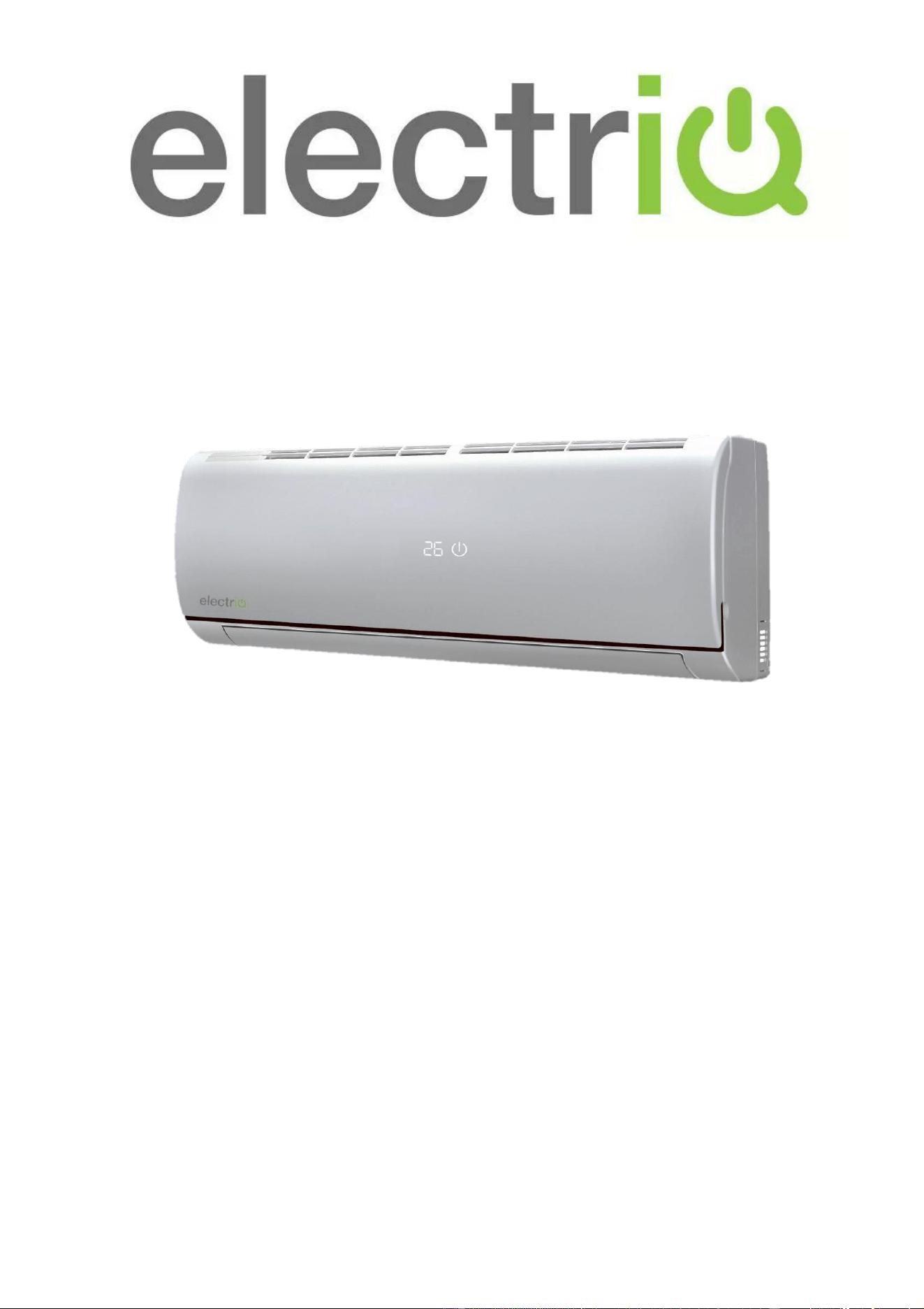
EASY FIT WALL MOUNTED INVERTER SPLIT
AIR CONDITIONER WITH HEAT PUMP
eiQ-9WMINV-V2 9,000 BTU
eiQ-12WMINV-V2 12,000 BTU
eiQ-18WMINV-V2 18,000 BTU
eiQ-24WMINV-V2 24,000 BTU
Thank you for choosing electriQ
Please read this user manual before using this innovative
Air Conditioner and keep it safe for future reference.
Visit our page www.electriQ.co.uk for our entire range of Intelligent Electricals
2
CONTENTS
SAFETY INSTRUCTIONS
3
OPERATION
5
REMOTE CONTROL
6
FILTERS
9
END OF SEASON
9
START OF SEASON
9
REPLACING THE BATTERIES
9
INSTALLATION GUIDE
10
INSTALLATION OF THE OUTDOOR UNIT
16
PIPELINES CONNECTION AND AIR PURGING
18
ELECTRICAL CONNECTION OF THE AIR CONDITIONER
20
TROUBLESHOOTING AND SELF DIAGNOSIS
23
TECHNICAL SPECIFICATION
25
APPENDIX
27
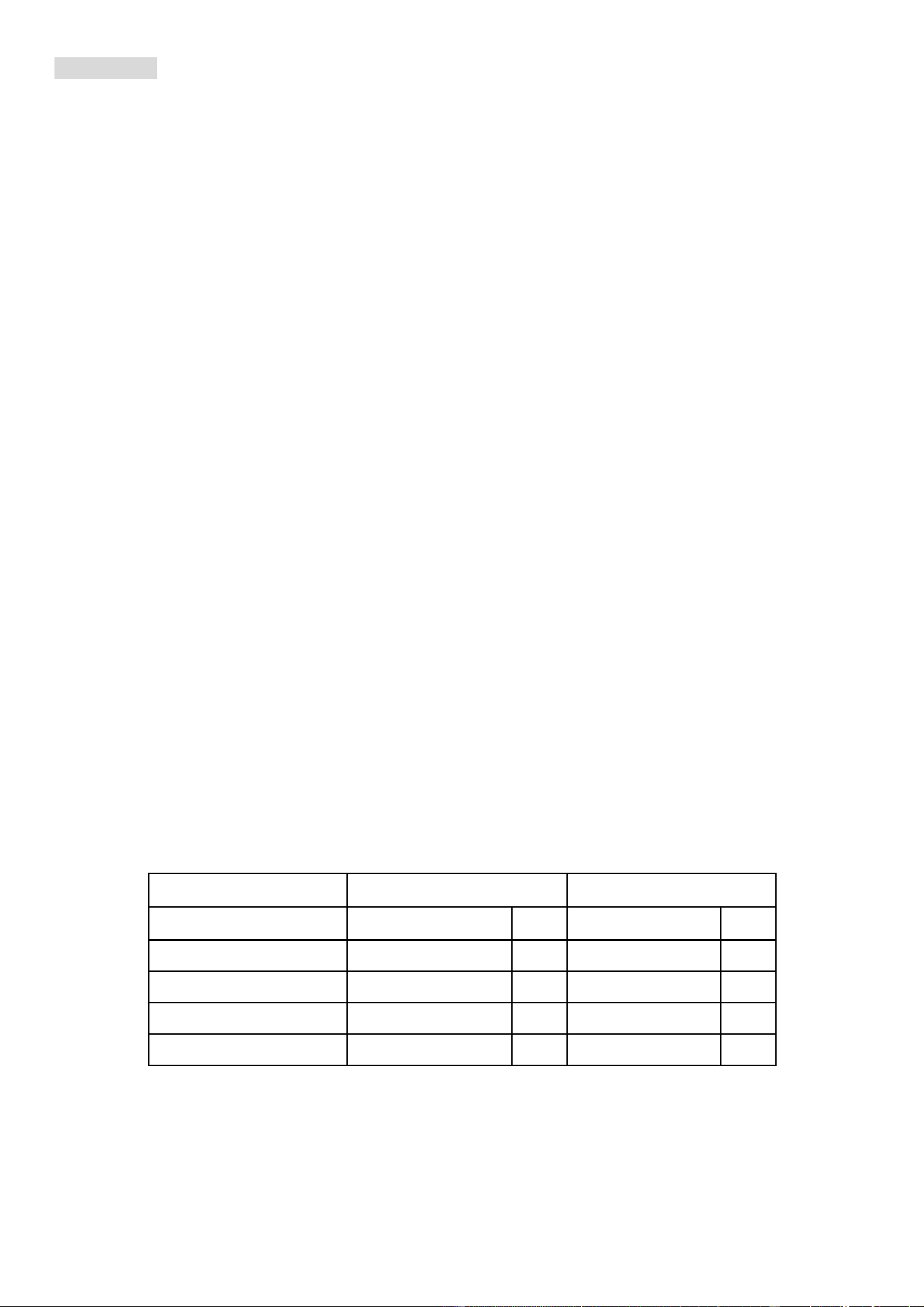
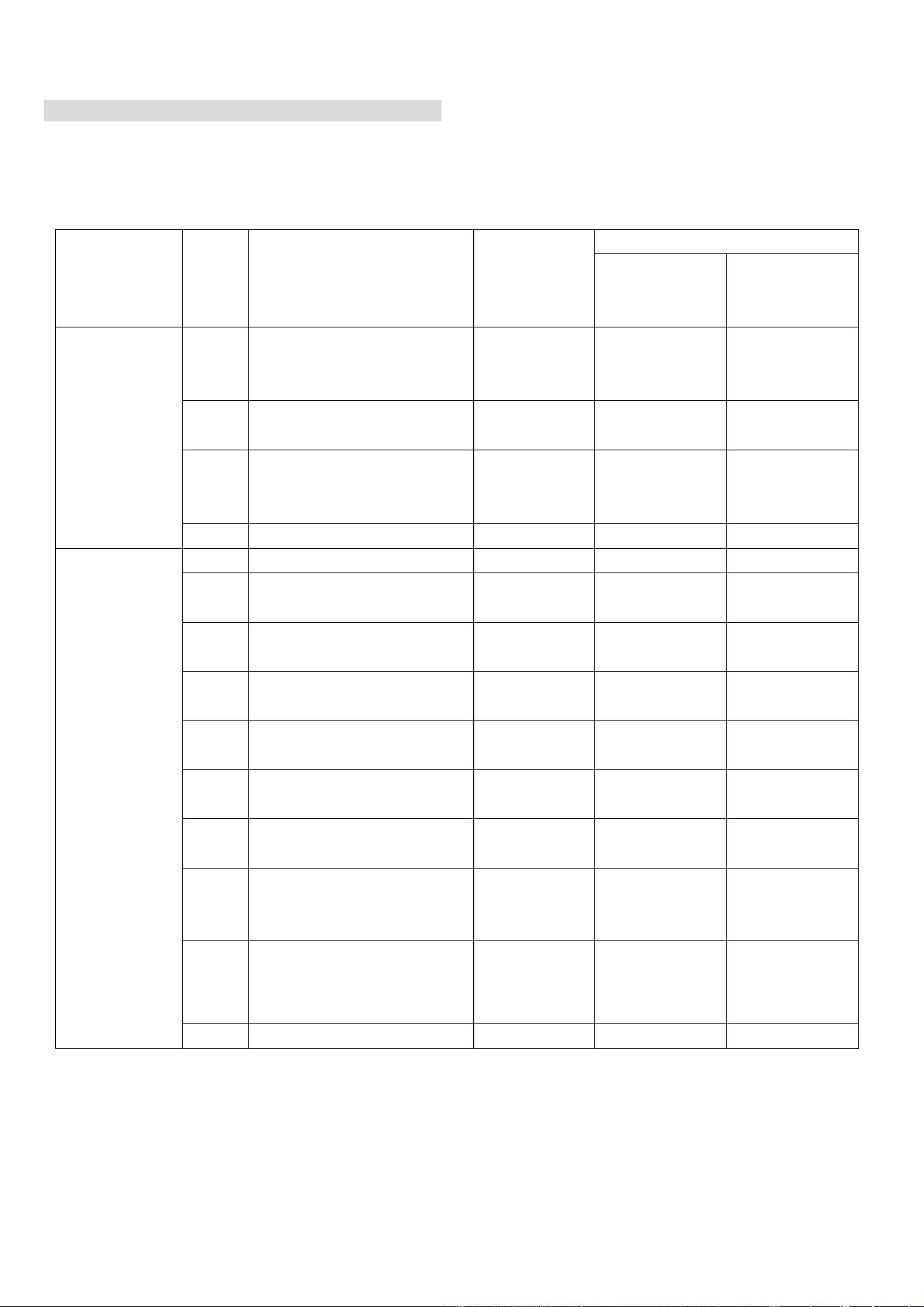
IMPORTANT NOTE:
This air conditioner is supplied in multiple boxes. Before an engineer visit is confirmed, ensure that all the
boxes required have been received in good condition and the codes on each box matches your model on
the table below:
Model
Outdoor
Indoor
QTY
QTY
eiQ-9WMINV-V2
eiQ-9WMINV EX-V2
1
eiQ-9WMINV IN-V2
1
eiQ-12WMINV-V2
eiQ-12WMINV EX-V2
1
eiQ-12WMINV IN-V2
1
eiQ-18WMINV-V2
eiQ-18WMINV EX-V2
1
eiQ-18WMINV IN-V2
1
eiQ-24WMINV-V2
eiQ-24WMINV EX-V2
1
eiQ-24WMINV IN-V2
1
The retailer and manufacturer will not be liable for failed installation, or problems occurring due to the above
not been checked prior to arranging installation.

3
SAFETY INSTRUCTIONS
Important!
• Carefully read the instructions before operating the unit
• This appliance comprises of an indoor unit and an outdoor unit. The slim wall mounted
evaporator is designed exclusively for indoor installations while the external condenser
should be installed outside, ensuring it is kept away from flood water or snow lines.
• Rating: This unit must be only connected to a 220-240 V / 50 Hz earthed power source.
• Installation must be in accordance with the regulations of the country where the unit is used.
• These air conditioners are supplied with refrigeration pipes and electrical cables. European
Union regulations requires for an F-Gas trained engineer to handle any operation where
non-qualified intervention could case fluorinated gas to escape. A commissioning certificate
must be issued with any installation.
• If you are in any doubt about the suitability of your electrical supply have it checked and, if
necessary, modified by a qualified electrician.
• This air conditioner has been tested and is safe to use. However, as with any electrical
appliance - use it with care.
• Disconnect the power before dismantling, assembling or cleaning.
• Avoid touching any moving parts within the appliance.
• Never insert fingers, pencils or any other objects through the guard
• This appliance is not intended for use by persons (including children) with reduced physical,
sensory or mental capabilities. It is also not intended for use by those with a lack of
experience and knowledge, unless they have been given supervision or instruction
concerning the use of the appliance by a person responsible for their safety. Do not leave
children unsupervised with this appliance.
• Do not clean the unit by spraying it or immersing it in water.
• Never connect the unit to an electrical outlet using an extension cord.
• Systems provided without a plug must be hardwired by a qualified electrician.
• Never operate this appliance if the cord is damaged. Ensure the power cord is not stretched
or exposed to sharp objects or edges.
• A damaged supply cord should be replaced by the manufacturer or a qualified electrician in
order to avoid a hazard.
• Any service other than regular cleaning or filter replacement should be performed by an
authorized service representative or a qualified air conditioning engineer. Failure to comply
could result in a voided warranty.
• Do not use the appliance for any purpose other than its intended use.
• The outdoor part of the air conditioner must always be stored and transported upright,
otherwise irreparable damage may be caused to the compressor; if in doubt we suggest
waiting at least 24 hours before starting the unit.
• Avoid restarting the air conditioning unit unless 3 minutes have passed since being turned
off. This prevents damage to the compressor.
• Never use the mains as a switch to start and stop the air conditioning unit. Use the provided
ON/OFF button located on the remote control.
• Always place the unit on a dry and stable surface. Install the outdoor unit on a wall using
wall mounting brackets or fix to a floor slab with special floor mounting fittings away from
flood or snow lines.
• The indoor unit should not be installed in damp environments such as laundry or wet rooms

4
Energy Saving and Unit Safety Protection Tips
Do not cover or restrict the airflow from the outlet or inlet grills.
For maximum performance the minimum distance from a wall or other objects should be
50cm.
Keep the filters clean. Under normal conditions, filters should only need cleaning once every
four weeks (approximately). Since the filters remove airborne particles, the frequency of
cleaning is dependant on the air quality.
During the initial start up set the fan speed to maximum and the thermostat to 4-5 degrees
lower than the current temperature. After, set the fan speed to low and set the thermostat to
your desired setting.
To protect the unit we recommend not using the cooling function when the ambient indoor
temperature is higher than 35℃.
To protect the unit we recommend not using the heating function when the indoor ambient
temperature is lower than 7℃.
Note the manufacturer operating temperature ranges at the end of this user manual.
5
OPERATION
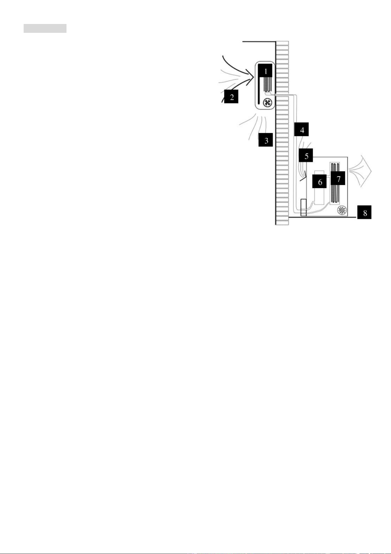
Cooling Mode
The compressor (6) in the exterior unit compresses the
refrigerant into a high- temperature, high-pressure gas.
When this gas flows along the cooling fins of the
condenser (7), heat is exuded and the gas condenses into
a liquid, which is led to the evaporator (1) within the indoor
unit. The liquid expands into a gas at a low temperature
and low pressure is converted. This gas absorbs the
warmth from the air in the room, the cooled air is blown
back into the room and the heat is moved to the
compressor along with the gas.
A fan (3) draws the air over the filter and blows the cooled air back into the room. A fan (8) draws air over
the condenser and blows warm air away.
1. Evaporator 2. Filter 3. Evaporator Fan 4. Gas Line 5. Liquid line
6. Compressor 7. Condenser 8. Condenser Fan
Heat Pump (Heating) Mode
The system operates in reverse: the condenser works as an evaporator, the evaporator as a
condenser: warm air is blown into the room. It is ideal as a maintenance heating when outside
temperatures are not too low and when the indoor temperature is above 7°C.
Dehumidifying
As with cooling, the moisture in the air condenses on the cold evaporator at room temperature acting
as a powerful dehumidifier. Please note as a cold surface is required for dehumidifying, cooling will
also occur in this mode.
6
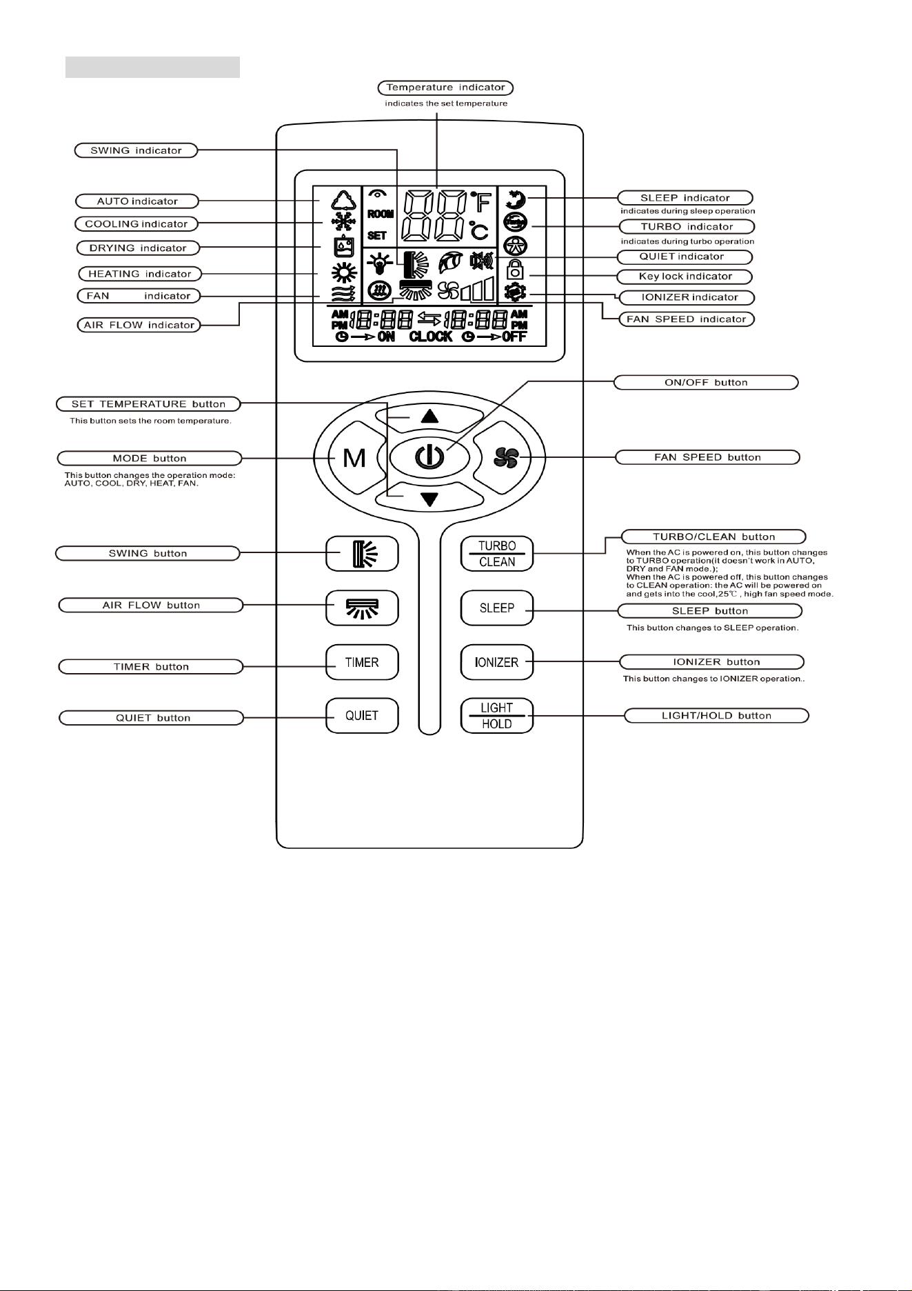
REMOTE CONTROL
The remote control has a range of up to 8m. Point the remote control at the receiver in the indoor unit.
A beep confirms that the remote control signal has been received.
NOTE: The LIGHT, IONISER and CLEAN functions may not be available on all models
REMOTE OPERATION
Turn the appliance on with the ON/OFF button. This starts the unit with the last used settings.
The ON/OFF button will also turn off the air conditioner.
This button turns on and off the horizontal
swing function
This button sets the unit to run at a low fan
speed to reduce operational noise
Short Press: Turn the display On/Off
Long Press: Lock / Unlock the remote
Press to turn On / Off the air conditioner
Indicates the fan speed selected
To change between Low, Medium, high and
AUTO fan speeds.
This button is used to turn on and off the
timer
This button turns on and off the vertical
swing function

7
TEMPERATURE
The desired temperature is set using the up and down buttons, within the range of 16°C – 32°C.
FAN SPEED
Use this button to set the fan speed between low, medium, high and automatic (the corresponding symbol
on the display will flash). The fan speed in the automatic setting is determined by the difference between
the desired temperature set and the room temperature.
COOLING MODE
1. Repeatedly press the MODE button until the COOL indicator appears.
2. Set the desired temperature using the TEMPERATURE up and down buttons.
3. Use the FAN SPEED button to set the fan speed.
HEATING MODE
1. Repeatedly press the MODE button until the HEAT indicator appears
2. Set the desired temperature using the TEMPERATURE up and down buttons.
3. Use the FAN SPEED button to set the fan speed.
FAN MODE
1. Repeatedly press the MODE button until the FAN indicator appears.
2. The temperature settings will not affect the fan operation
3. Use the FAN SPEED button to set the fan speed.
DEHUMIDIFY MODE
1. Repeatedly press the MODE button until the DEHUMIDIFY indicator appears.
2. The FAN button does not work in dehumidify mode. The fan speed will always be low in this mode.
Also temperature cannot be adjusted in dehumidifying mode
AUTO MODE
1. Repeatedly press the MODE button until the AUTO indicator appears. Set the desired temperature
under auto mode to the required level between 16~32 °C
2. The difference between the set temperature and the room temperature determines how the air
conditioner operates: cooling, heating or fan.
3. Once the temperature is set in auto mode it is not possible to amend it. It the desired temperature
requires changing, change the unit out of Auto mode before changing it back.
4. The unit will operate in the auto selected mode until set temperature is reached than switches the
compressor off. Mode is locked until reset via mode button.
5. You can use the FAN button to set the fan speed while in Auto mode.
6. All indoor units must be operating in the same mode, otherwise a mode mismatch error will show.
SLEEP MODE
During sleep mode the unit will operate with a low fan speed to minimise the operational noise of the unit.
1. Press the SLEEP button
2. Set the desired temperature.
3. Press the SLEEP button; SLEEP indicator will appear on the display. Cancel the sleep mode by
pressing this button again.
CLEAN (Not available on all models)
When pressed while the unit is in standby mode, the unit will power on in high speed fan mode, and run
through the cleaning mode, before returning to standby mode.

8
TURBO (Not available on all models)
When pressed the unit will operate at maximum fan speed and maximum cooling for 15 minutes.
1. Set the air conditioner to run with the settings required after Turbo has completed.
2. Press the TURBO button.
TIMER
OFF FUNCTION (While the air conditioner is on)
1. Ensure the air conditioner is turned on and running with your desired settings
2. Press the TIMER button to turn on the timer.
3. Use the up and down button to set the timer between 1 and 24 hours.
4. Once the time you have set has elapsed, the appliance will switch itself off.
5. To cancel the timer function before the set time has elapsed, press the TIMER button again.
ON FUNCTION (while air conditioner is in standby)
1. Ensure the air conditioner is in standby mode.
2. Press the TIMER button to turn on the timer.
3. Use the up and down button to choose from 1-24 hours timer setting.
4. Set the desired operation, temperature, fan speed, etc.
5. Once the time you have set has elapsed, the appliance will switch itself on.
6. To turn off the timer function before the set time has elapsed, press the TIMER on button again.
IONISER (Not available on all models)
When turned on the ioniser uses an electrical charge to remove particles from the air, improving air quality.
QUIET BUTTON (Not available on all models)
When activated the air conditioner will operate with settings such as low fan speed to minimise the
operational noise.
IMPORTANT
AUTO RESTART: The air conditioner will automatically restart when electricity is restored after a power cut.
If in doubt, check the settings.
RANGE OF THE INTERNAL THERMOSTAT: The internal thermostat can be set at a desired temperature
between 16 and 32°C. Note that whether the desired value can be achieved depends on a number of
factors including the unit’s power, room size, temperature and insulation of the room.
RANGE OF HEAT PUMP FUNCTION: The heat function can be used when the external ambient
temperature is 5°C or higher. The performance of the heat pump will degrade as the external temperature
reduces.
CAPACITY: The required cooling or heating capacity depends greatly on the location and/or use of the
room where the air conditioner is installed. Strong sunlight and the presence of people, lights or equipment
create an additional heat load. Normal living spaces require about 100 W per square metre of floor surface.
In strong sunlight or if other sources of heat are present, this may be as much as 350 W/sqm.
Tip: On warm days, let the air conditioner cool the room as much as possible during the night and set the
temperature constant from night to daytime.
EMERGENCY START: In the event of a problem, the air conditioner can be operated using the emergency
button under the panel in the indoor unit. Open the front panel and press the button, the air conditioner will:
-heat if the room temperature is 20 °C or less, cool if the room temperature is 25 °C or more and for values
in between will dehumidify.
9
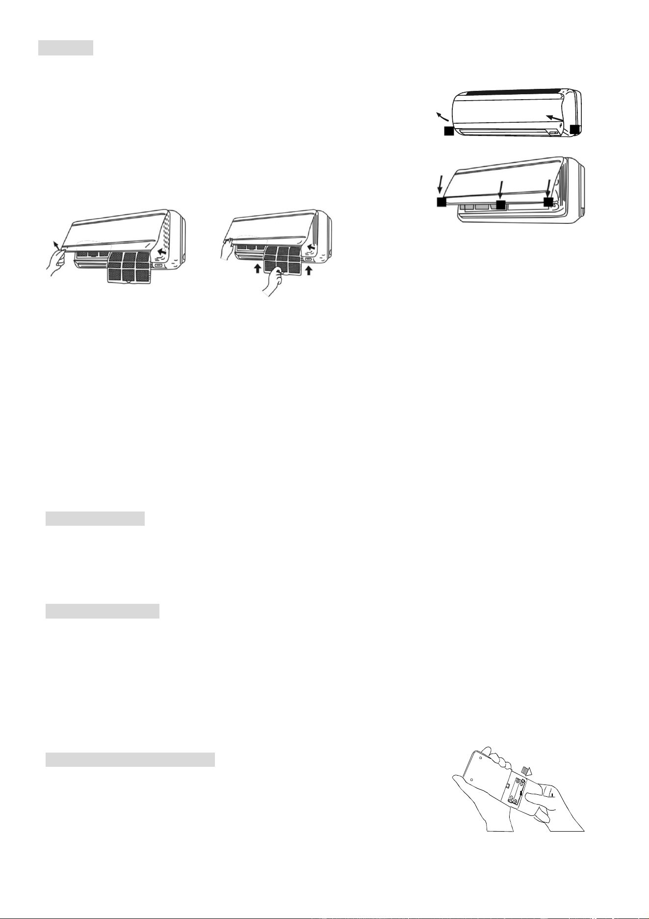
FILTERS
Turn off the appliance from the consumer unit before attempting to service the filters.
Opening the front panel: at the A recesses, pull the front part up with
both hands. The front panel will stay horizontal (at around 90°).
Closing the front panel: press the front part down at the sides at B
and in the middle at. Make sure it is properly closed (click).
1. Hold the front panel open (or put it in horizontal position) and remove the filter(s).
2. Use a vacuum cleaner to remove dirt. If the dust filter is very dirty, it may be washed in lukewarm
water with a very small amount of neutral detergent. Rinse well and allow to dry completely (not in
direct sunlight or near a source of heat).
3. Keep the grid panel open and reinstall the filter(s). Press the panel shut; a click indicates it is
closed properly.
4. Restore the power from the consumer unit and turn the air conditioner on.
Indoor Unit: While the unit is disconnected from power dust regularly with a dry cloth or slightly damp
paper towel. Never use chemicals or solvents. Never spray a liquid in or over the appliance.
Exterior unit: While the unit is disconnected from power. Remove dirt and keep the air intake and exhaust
openings free of debris, etc. Cleaning with chemicals may cause damage.
END OF SEASON
If the air conditioner is not going to be used for an extended period:
• Set in fan mode on a warm day so that the inside of the appliance fully dries out.
• Switch off the power from fuse box and remove the batteries from the remote control.
• Clean the filters
START OF SEASON
If the air conditioner is to be used again after an extended period:
• Check that the air intake and exhaust openings of the indoor and exterior units are not blocked. Remove
any dirt and debris.
• Check that the filters are installed and are clean.
• Check that the condensation outlet drains properly and there is no dirt or organic blockage (otherwise
leakage may occur)
• Install 2 AAA batteries in the remote control.
• Turn the appliance on, set the time and desired settings.
REPLACING THE BATTERIES
• Remove the battery cover.
• Replace the AAA batteries, following the markings for the polarity
• Replace the battery cover.
• Press the on/off button; if no symbols appear on the display, the
batteries are empty or have been incorrectly installed.
B
C
B A

10
INSTALATION GUIDE
SAFETY
Only qualified personnel should install this appliance.
This installation manual is intended for use by individuals possessing adequate
backgrounds and qualifications in electrical, electronic, refrigerant and mechanical fields.
Any attempt to install or repair the appliance may result in personal injury and/or property
damage.
The manufacturer and retailer cannot be held responsible for the interpretation of this
information, nor can it assume any liability in connection with its use.
The units are designed for permanent installation.
The equipment is designed for domestic or office use and we are not making any
endorsements for its use in industrial or maritime environments.
Do not place near sources of heat, vapours, industrial machine oil or other flammable
gases.
High frequency waves generated by radio equipment, welders and medical equipment will
interfere with the normal operation of the unit.
Install this device only when it complies with local/national legislation, ordinances and
standards. Check the mains voltage and frequency. This unit is only suitable for an earthed
electrical supply, connection voltage 230 V~ / 50 Hz.
The information, specifications and parameter are subject to change due to technical
modifications or improvement without any prior notice. The accurate specifications are
presented on the nameplate label.
Please read this installation manual completely before installing the product.
When the power cord is damaged, replacement work shall be performed by authorized
personnel only.
Installation work must be performed in accordance with all European, national and / or
local directives and standards and must be done by authorized personnel only.
Always make sure to wear the correct personal safety protections such as protective
eyewear, gloves, ear protection etc.
This air conditioner contains a refrigerant and can be classified as pressurized equipment.
Therefore always contact a qualified air conditioning engineer for installation and
maintenance of the air conditioner. The air conditioner must be inspected and serviced on
an annual basis by a qualified air conditioning engineer.
For your convenience you can download the latest version of the user / installation manual
from www.electriQ.co.uk
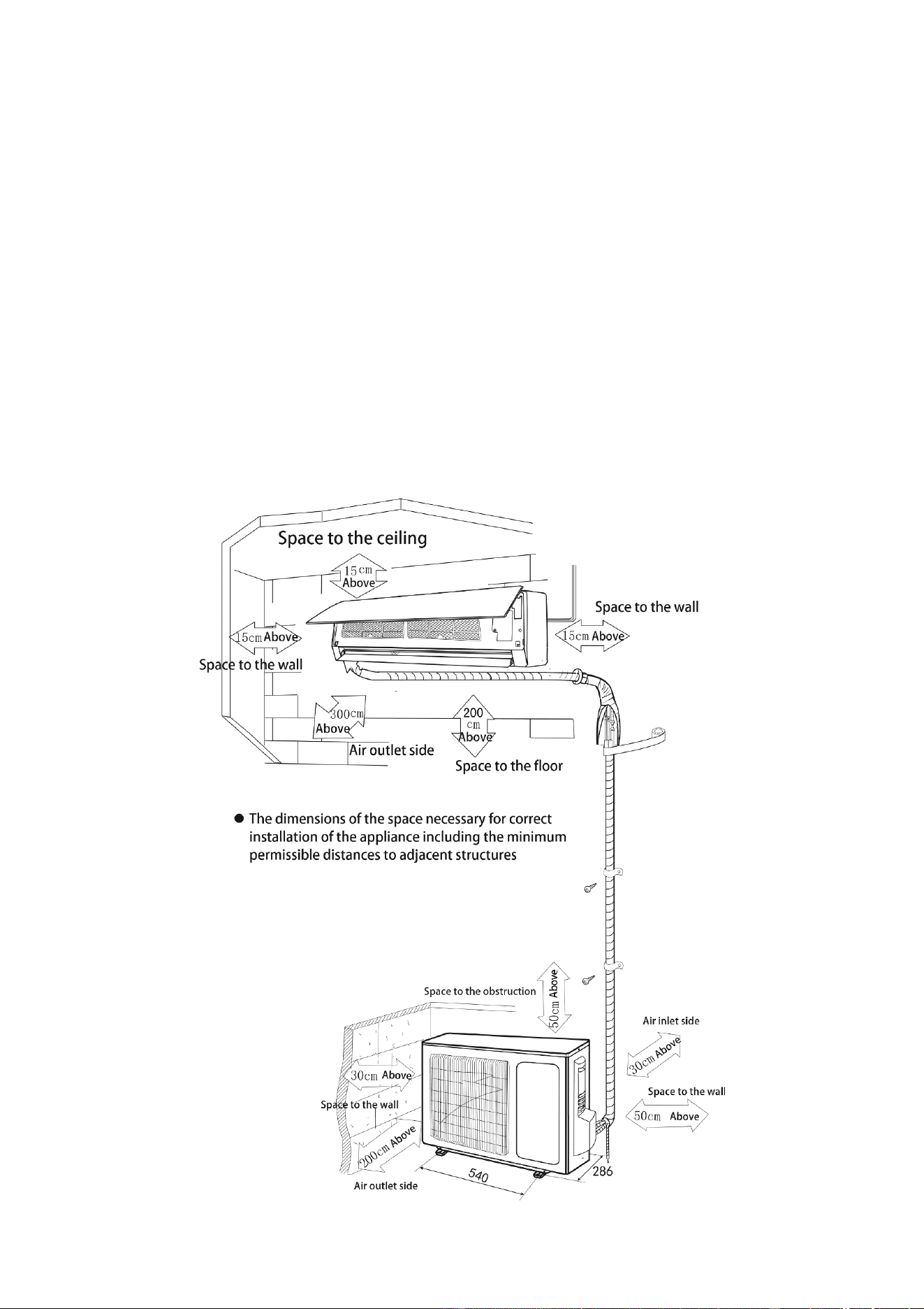
INDOOR UNIT POSITION
The air inlet and outlet vents should be away from any obstruction, ensuring that there is a
good airflow through the whole air-conditioned space.
Select a position where the condensing water can be easily drained out, and the indoor unit
can be easily connected to outdoor unit.
The wall where the unit is fixed should be strong enough to withstand the full weight and
vibration of the unit.
The unit should be accessible for service and maintenance.
The height of the installed unit should be ideally more than 200cm from floor.
The air conditioner must not be installed in a wet environment such as a bathroom, shower
or swimming pool etc.
11
OUTDOOR UNIT POSITION
A convenient position, dry and well ventilated, outside of direct sunlight or strong winds, which
is not on flood line and where noise and airflow does not cause interference or inconvenience.
Select a location where there should be no obstructions to the inlet and outlet vents.
The location should be able to withstand the full weight and vibration of the outdoor unit and
permit safe installation.
Make sure that the outdoor unit installation is made in respect to installation dimension
diagram with easy maintenance access.
Select a place where it is out of reach of children.
Do not block utilities access or fire escapes.
The external unit must be lifted and put in place by two people or by specialised equipment.
NOTES:
Only use the correct power supply voltage making sure the correct sized power cables are used
The appliance shall be installed in accordance with standard wiring regulations by qualified
personnel.
Only replace fuses according to their printed rating or corresponding pcb boards.
RECOMMENDED INSTALLATION SPACING DIAGRAM
12
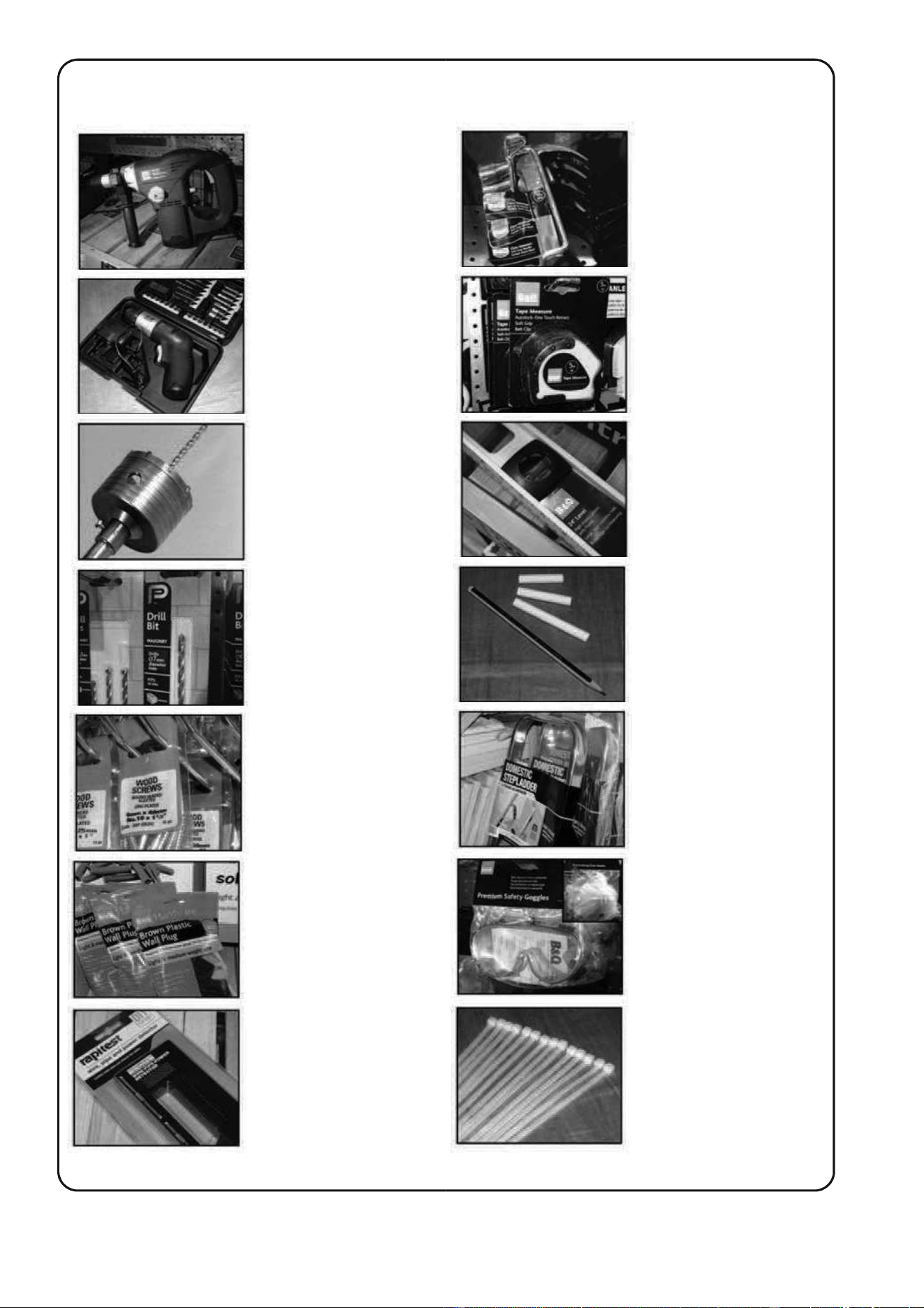
TOOLS RECOMMENDED FOR INSTALLATION
Electric drill
Screwdrivers
Core
hole
cutter
Number 14 (7mm)
Masonry drill bit
1.5
inch number
10 screws
(Roundhead slotted)
7
mm
Wall plugs
Pipe & cable detector
Hammer
Tape measure
Spirit level
Pencil and
chalk
Small
stepladder
Protective glasses
and mask
4
inch plastic ties
13
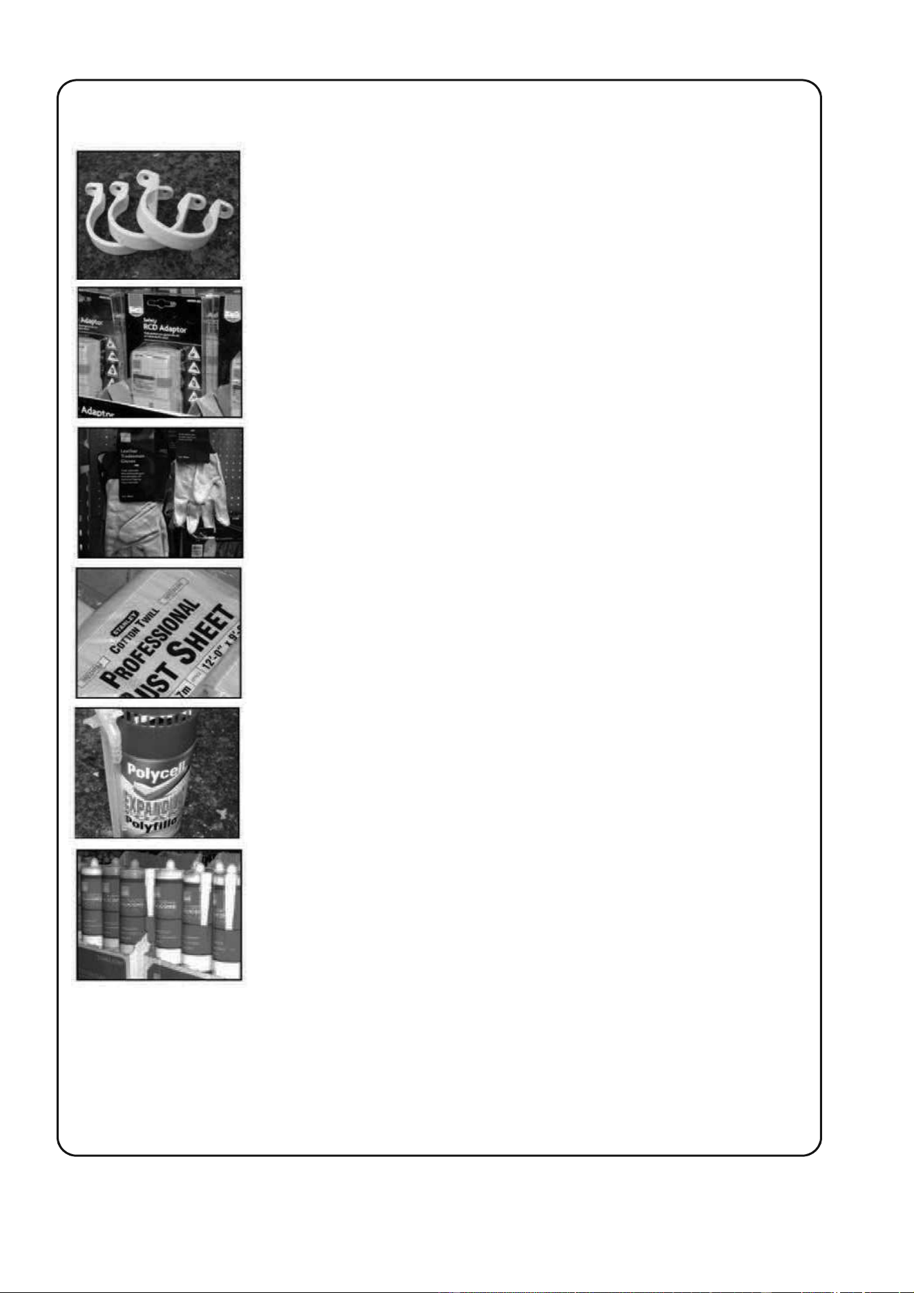
Also the following
2
inch Pipe clips
Circuit breaker when drilling inside and out
Garden gloves when lifting the outdoor unit
Dustsheets
Foam Filler
Silicone sealant and gun
14
15
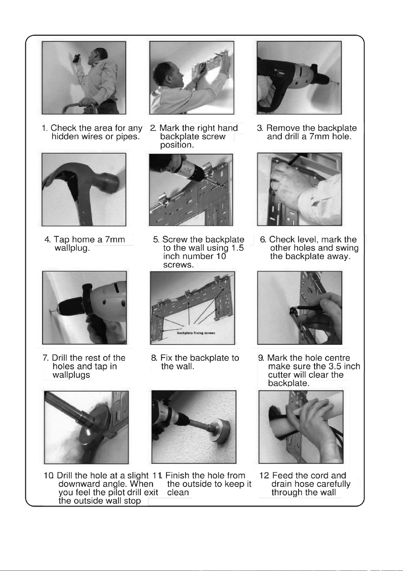
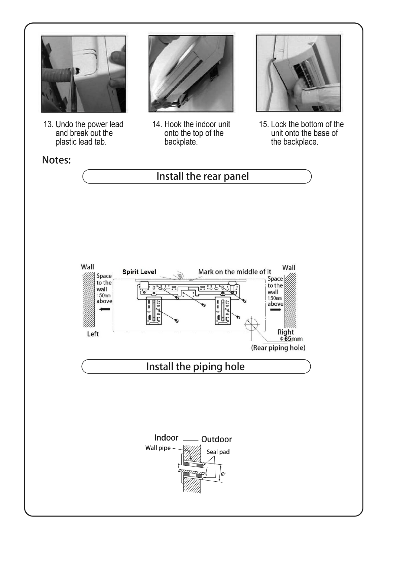
1. Drill a piping hole (65mm) through the external wall at a slight downwards angle
2. Insert the piping sleeve in to the hole to prevent damage to the connecting copper pipes and
wiring when they are passed through the opening.
1. Always install the rear bracket horizontally. The pipes in the unit can be installed to the left (default) or can
be changed to exit on the right side. The outlet of the water tray needs adjusting so the water follows the
gravity fall. If the drain is running against gravity at any stage, goes above the tray level or the run is longer
than 5 meters, an inline water pump must be used.
2. Fix the rear bracket to the wall using screws and suitable wall plugs.
3. Be sure to use the correct screws and fixings for the type of wall where the bracket is installed, and that the
mounted bracket can withstand at least 60 kgs of weight. The weight should be equally distributed between
each screw.
65
16
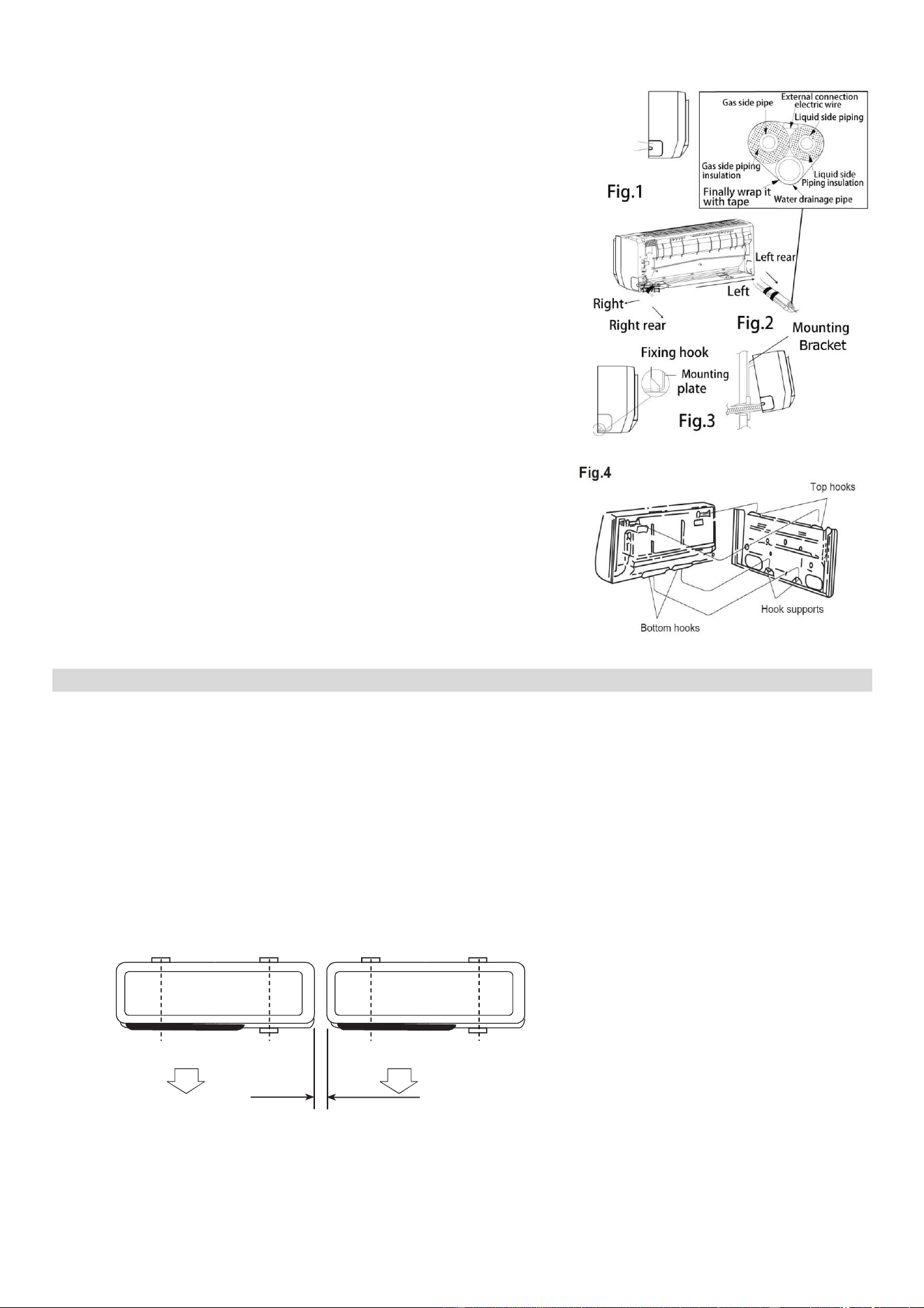
The pipework can be fed out of either the right or the left of the indoor
unit as seen in fig. 1. Please cut off the pipe hole guards if you are
changing the pipe position. The unit also features alternative guards
for more pipe positioning.
Make sure that the drain pipe is routed under the pipework. (Fig.3)
(When the drain pipe passes through the room interior, some
condensed water might occur to its surfaces if the humidity is very
high).
Tidy up the copper pipes, electrical cables and water drains and pass
them through the piping wall hole drilled earlier (fig.2).
Hang the mounting slots of the indoor unit on the wall mounting
bracket making sure it is tight in place (fig.3), so that the hooks at the
bottom of the indoor unit match the hooks of the wall mounting
bracket (fig.4)
Notes:
1. The height of the installed unit is recommended to be > 200 cm.
2. Either the indoor unit or the outdoor unit can be higher, but the
height difference must comply with a max. 5 metres level
difference.
3. Try to avoid the bending of the pipes as much as possible so as
to prevent possible negative impacts upon the performance of
the unit.
INSTALLATION OF THE OUTDOOR UNIT
Try to move the product to the installation location in its original packaging to prevent damage.
As the gravity centre of the unit is not at the installation centre, special caution should be taken when using
hoisting cables to lift the unit.
During transport, the outdoor unit must not be tilted in excess of 45 degrees (also do not store the unit
horizontally.
Use expansion bolts to fix the mounting supports to the wall;
Use bolts and nuts to fix the outdoor unit firmly on the support, ensuring the installation is level; if the unit
is installed on a wall or a rooftop, the supports have to be firmly fixed so as to resist earthquake or
strong wind.
Dimensions for parallel indoor units installations
300
mm(1')min
17
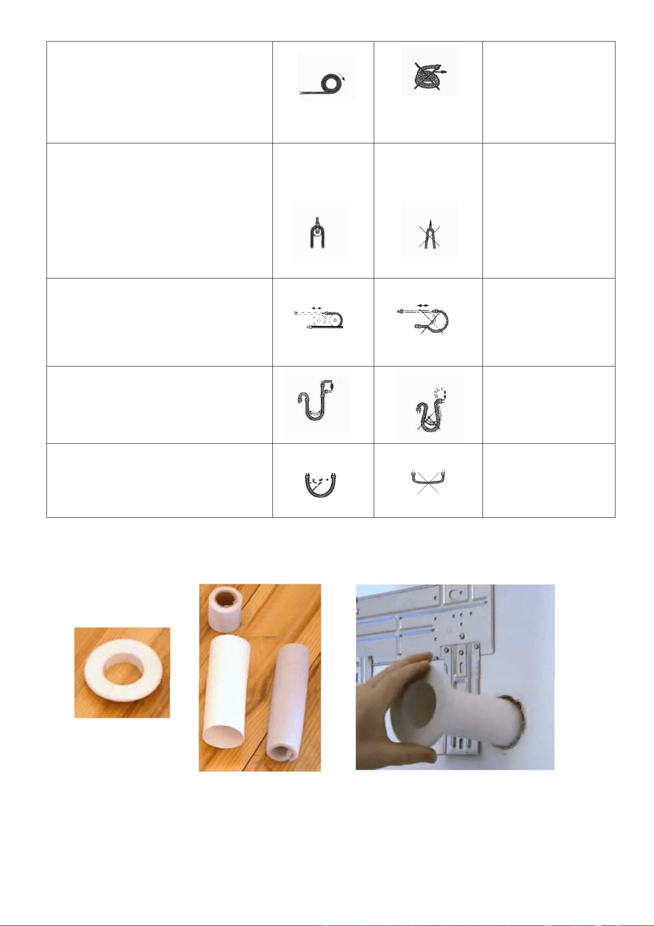
To avoid damaging the pipework during
unrolling. Ensure the packed soft pipes
are vertical before extending
Please do not
extend only one
side of the
pipework, as this
could kink or
damage the
pipework
Please make use of a semicircle pulley
to keep the allowed bending angle
Ensure the bends
are not too severe,
as this could
restrict refrigerant
flow, reducing
performance or
preventing
operation.
Please use a twisting wheel to avoid
improper bending.
Over bent soft
pipes will lead to
irregular bending
Please use a rigid elbow to maintain the
bending angle while soft pipes operating.
Avoid bending the pipe where possible,
where bends are necessary their radius
should be kept as large as possible.
Do not use short
sharp angle
bends.
Notes: Please ensure you use the protective plastic tube and sleeves before passing the copper pipes through
the wall in order to avoid pipe damage.
18
PIPELINES CONNECTION & AIR PURGING
No dust or any other particles, air or moisture should be allowed to enter the air conditioning system.
Careful attention should be paid when the pipeline connection of the units are made. Try to avoid
repeated curves as much as possible; otherwise damage to the copper pipes may occur. Suitable
wrenches should be used when the pipeline connection is done so as to ensure the appropriate torque is
applied (refer to following torque table).
Excessive torque action might damage the joints while too little torque might lead to leakage.
Torque based upon the wrench to be used
Copper pipe diam.
Tightening torque
Strengthened tightening
torque
6.35(1/4")
160kgf.cm(63kgf.inch)
200kgf.cm(79kgf.inch)
9.52(3/8")
300kgf.cm(118kgf.inch)
350kgf.cm(138kgf.inch)
12.7(1/2")
500kgf.cm(197kgf.inch)
550kgf.cm(216kgf.inch)
15.88(5/8")
750kgf.cm(295kgf.inch)
800kgf.cm(315kgf.inch)
19.05(3/4")
200kgf.cm(472kgf.inch)
1400kgf.cm(551kgf.inch)
If you are installing a split system with easy fit connectors follow the procedures below:
1. Remove the dust caps from the indoor and outdoor units and the connecting pipe.
2. Align the joint of the connecting pipe between the indoor and outdoor and tighten the connecting nut by
hand to prevent cross threading. Secure them with a wrench, applying the maximum torque as shown
in the table above.
3. Pressure test and vacuum pump the pipework.
4. Remove the two valve core caps from the outdoor unit and turn on the high and low pressure valve
cores with an socket wrench, then tighten the two valve core caps of the outdoor unit. Finally you can
wrap hot insulating tape around the joints of indoor and outdoor units
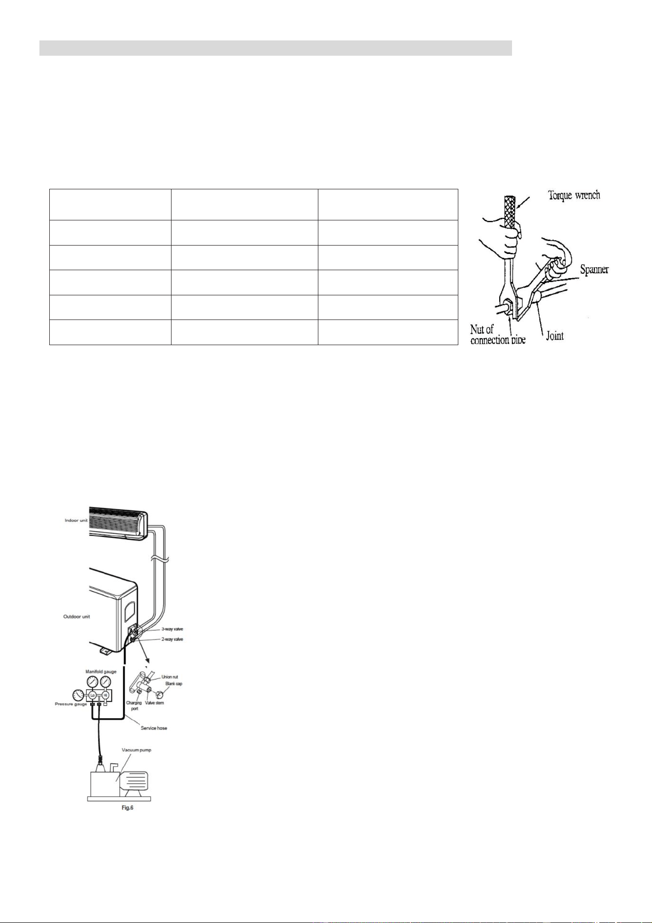
AIR PURGING WITH A VACUUM PUMP
1. Check that pipelines connection have been properly connected,
remove the charging port cap, and connect the manifold gauge and
the vacuum pump to the charging valve using service hoses as shown
2. Open the valve on the low-pressure side of the manifold gauge, then
run the vacuum pump. Vacuum the indoor unit and the connecting
pipes until the pressure in them lowers to below 1.5mmHG (The
operation time for vacuuming is about 10 minutes). When the desired
vacuum is reached, close the low pressure valve on the manifold and
stop the vacuum pump.
3. Disconnect the service hoses and fit the cap to the charging valve.
4. Remove the blank caps, and fully opens the spindles of the 2-way and
3-ways valves with a service valve wrench.
5. Tighten the blank caps of the 2-way and 3-ways valves, applying the
torque listed in the table above.
ADDING REFRIGERANT
Refrigerant must be added if the pipework
measures more than 5 metres (16'5") in length.
This operation can only be performed by a
professional F-Gas engineer, for the additional
refrigerant quantity, please refer to the table.
GAS LEAKAGE INSPECTION
After the pipeline connection is done, use a leakage inspection device to carefully check if there is any
leakage at the joints. This is an important step to ensure the quality of installation. Once a leak is detected,
proper action should be taken immediately.
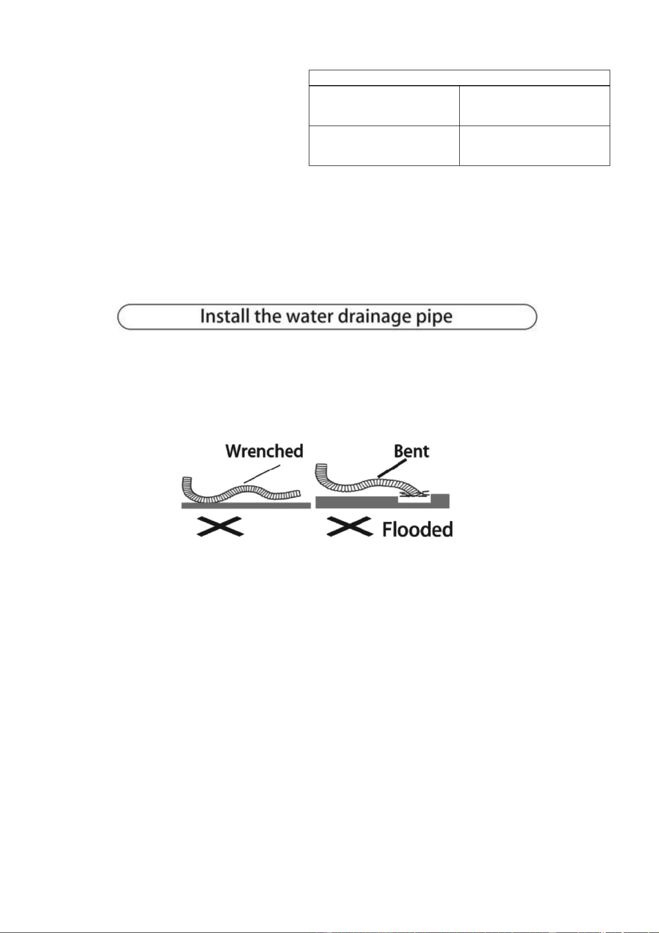
1. For good drainage, the drain hose should be angled downwards.
2. Do not pull on or bend the drain hose or flood its end with water.
3. When the long drainage hose passes through indoor areas, it should be wrapped in insulation to
prevent condensation building.
ADDITIONAL REFRIGERANT AMOUNT
Liquid pipe diameter
6.35 (1/4")
Liquid pipe diameter
9.52 (3/8")
(pipework length - 5) m
x 30g
(pipework length - 5) m
x 65g
20
ELECTRICAL CONNECTION OF THE AIR CONDITIONER
The electrical connections can be found under the protective plastic cover. Remove this from
the side of the outdoor unit to gain access to the electrical connections.
Connect the indoor power and control wires with the matching outdoor wire as per the
electrical diagram.
Do not attempt to connect the wires in a different way to the diagram on the air conditioner as
this could damage the unit and invalidate the warranty.
Secure the wires and replace the cover before operating the unit.
The appliance should be installed in accordance with national wiring regulations.
If the supply cord is damaged, it must be replaced by the manufacturer, its service agent or a
suitably qualified person in order to avoid a hazard.
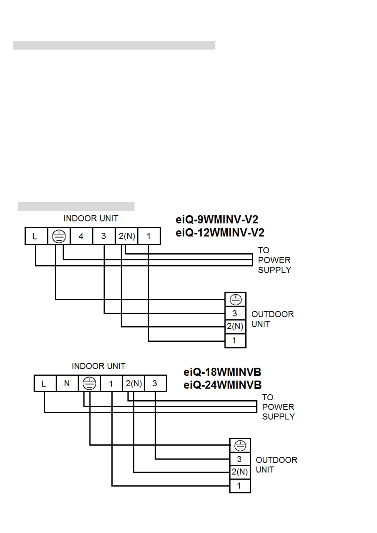
SIMPLIFIED WIRING DIAGRAMS
21
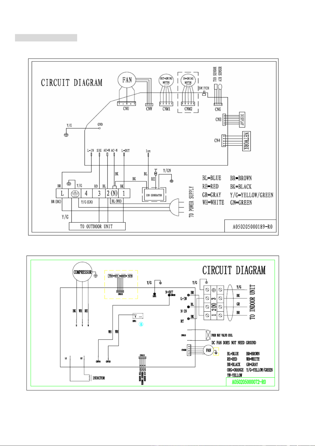
CIRCUIT DIAGRAMS
eiQ-9WMINV-V2 / eiQ-12WMINV-V2
INDOOR UNIT
OUTDOOR UNIT
22
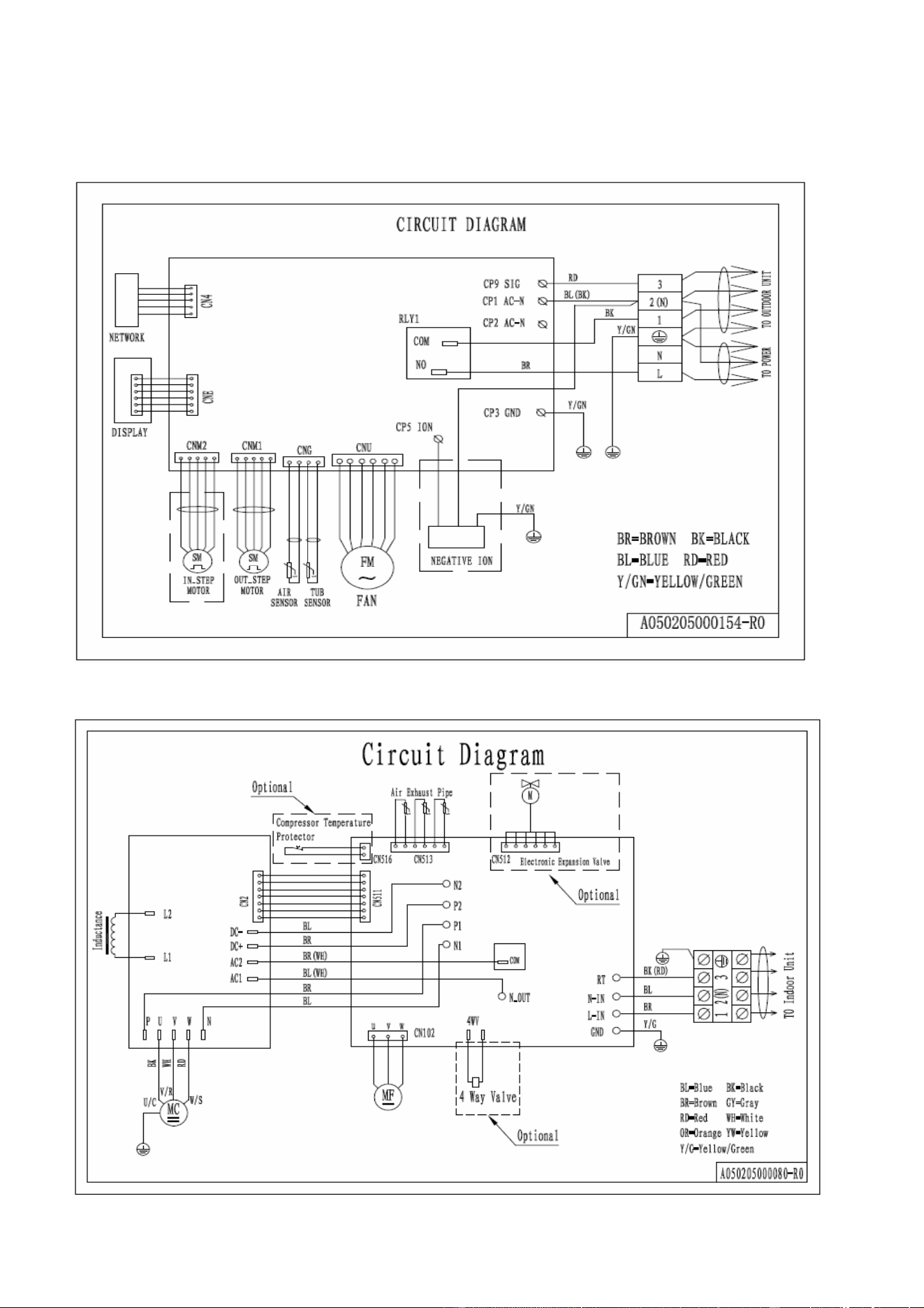
eiQ-18WMINV-V2 / eiQ-24WMINV-V2
INDOOR UNIT
OUTDOOR UNIT
23
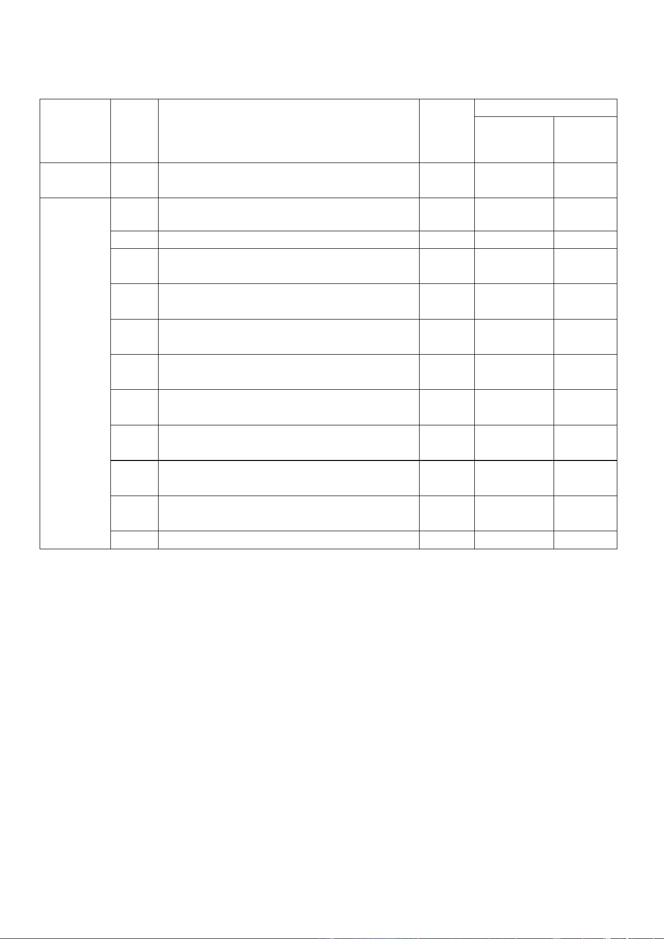
TROUBLESHOOTING AND SELF DIAGNOSIS
electriQ air conditioners have an advanced self-diagnosis system allowing them to display the service information
INDOOR UNIT ERROR CODE LIST.
Check
No
Description
Display Code
Unit Display Status
Display LED
(light flashing)
Power on LED
(light)
Indoor
parts
1
The communication faults in
the indoor and outdoor
units
F1
1
On
2
Indoor ambient temp.
sensor fault
F2
2
On
3
Indoor coil temperature sensor
fault (Include: Inlet,
middle of pipe, outlet.)
F3
3
On
4
Indoor fan fault
F4
4
On
Outdoor
parts
1
Outdoor module fault
F5
5
On
2
Outdoor ambient temp.
sensor fault
F6
6
On
3
Outdoor coil temp. sensor
fault
F7
7
On
4
Compressor suction temp.
sensor fault
F8
8
On
5
Compressor discharge
temp. sensor fault
F9
9
On
6
Inductor of current or
voltage fault
FA
10
On
7
Compressor drive
abnormal fault
FC
11
On
8
Power supply phase lacking or
phase
sequence fault
FD
12
On
9
Return-air sensor abnormal
(Include these roads
A,B,C,D)
FE
13
On
10
Outdoor DC Motor Fault
FH
15
On
Note A: If the unit is faulty the POWER ON LED will be on and the display LED will flash the corresponding number of
times as shown in the table. Both LEDs will go off for 2 seconds then cycle will repeat.
Note B: although the above diagnostic information is commonly applicable in most air conditioners, there may be
exceptions, please contact the manufacturer for help.
24
INDOOR UNIT PROTECTION CODE LIST.
Check
No
Description
Display
Code
LED
Display LED
(light flashing)
Power on
LED
(light)
Indoor
parts
1
Evaporator temp protection
P1
1
On
Outdoo
r
parts
1
Overheat, over current protection of inverter
module
P2
2
On
2
Over current protection
P3
3
On
3
Compressor discharging
temp. protection
P4
4
On
4
Overheat of compressor
top protection
P5
5
On
5
Compressor suction temp.
protection
P6
6
On
6
Power supply over current
/ over voltage protection
P7
7
On
7
Low pressure of gas
return protection
P8
8
On
8
High pressure of
discharge protection
P9
9
On
9
High temp. of condenser
protection
PA
10
On
10
High temp. of outdoor
ambient protection
PC
11
On
11
Other protection
PF
12
On
Note A: If the unit is faulty and POWER ON LED will be on and the display LED will flash the corresponding
number of times as shown in the table. Both LEDs will go off for 2 seconds then cycle will repeat.
B: Limits for temperature, current, voltage etc of each protection and examples for other faults.
P1: Under cooling mode, when temperature for the middle of the pipe is < -1
o
C, the unit will stop and start
this protection.
Under heating mode, when temperature for the middle of the pipe is > 63
o
C, the unit will stop and start this
protection
P2: The maximum current should be no more than 15A. (Different models have different values)
P3: If the outdoor motor stops, the heat exchanging efficiency becomes poor. Then the unit will have this input
AC over current protection.
P4: When the discharge temperature of the compressor is >105
o
C, the unit will stop to protect.
P5: When the temperature of compressor top is higher than the temperature controller, the unit will stop to
protect.
P6: When the suction temperature of compressor is <2
o
C, the running frequency begins to decline. When the
temperature is >4
o
C, the running frequency will return to the normal condition.
P7: When the power supply is <170V or >265V, the unit will stop to protect.
P8/P9: When the system pressure exceeds the min or max pressure, the compressor will stop to protect.
(Not all models have this feature)
PA: When the outdoor coil temperature is >65
o
C, the unit will stop to protect.
PC: When the outdoor ambient temperature is <-10
o
C or >55
o
C, the unit will stop to protect.
PF: Other fault like the communication fault between the outdoor main board and the IPM board.
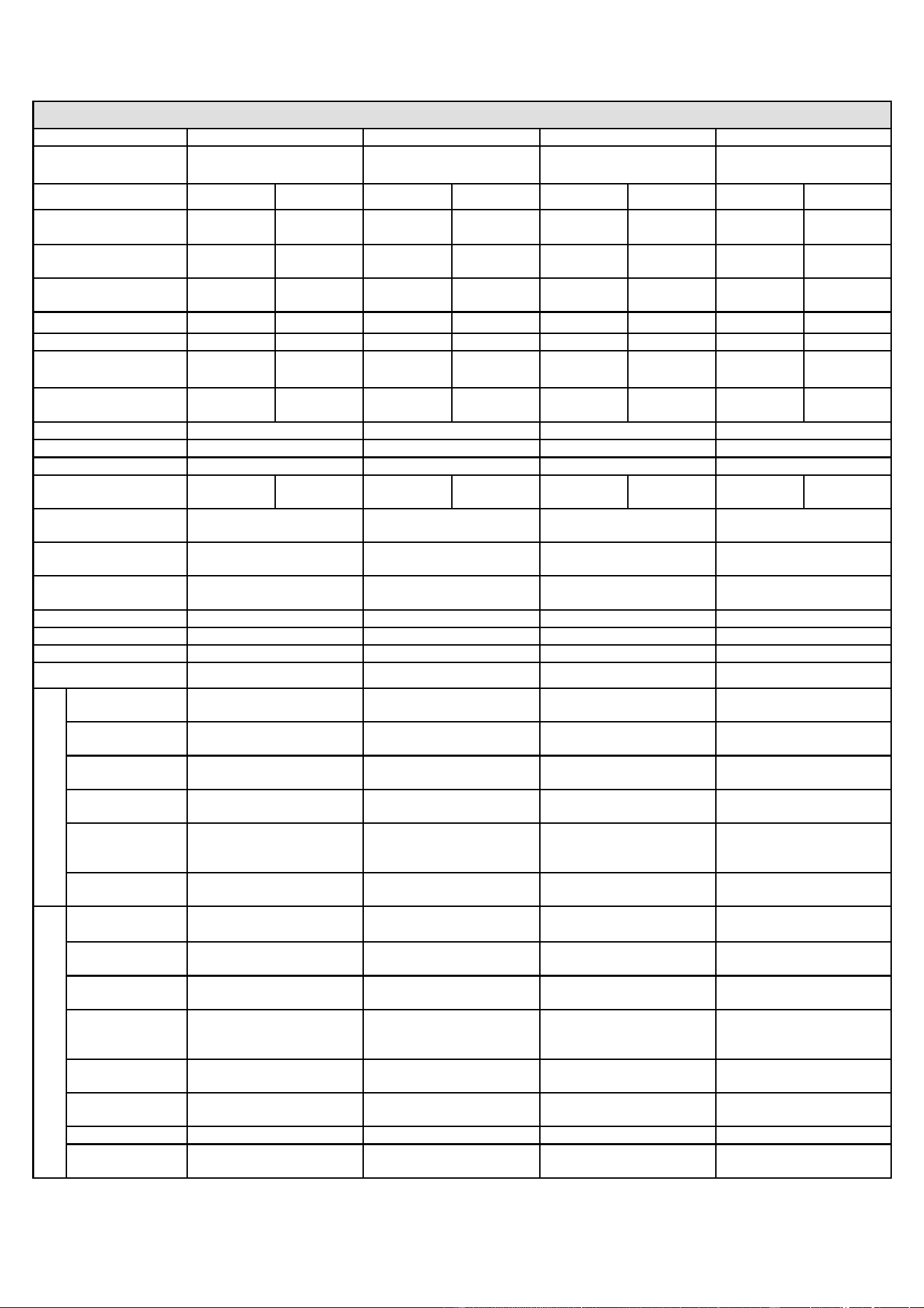
25
TECHNICAL SPECIFICATIONS
Model
eiQ-9WMINV-V2
eiQ-12WMINV-V2
eiQ-18WMINV-V2
eiQ-24WMINV-V2
Rated voltage and
frequency (Ph-V-Hz)
1-220-240/50
1-220-240/50
1-220-240/50
1-220-240/50
Mode
Cooling
Heating
Cooling
Heating
Cooling
Heating
Cooling
Heating
Rated capacity (W)
2500
(1500~3200)
2500
(1480~3350)
3500
(1600~3950)
3600
(1550~4250)
5100
(1800~5900)
5200
(1800~6100)
6100
(2500~6500)
6100
(2100~7000)
Cooling power input
(W)
670
(390~1110)
660
(320~940)
1090
(450~1400)
990
(370~1270)
1600
(420~2100)
1400
(410~2150)
1900
(700~3000)
1680
(450~2300)
Heating current input
(A)
3.0
(1.9~4.8)
2.9
(1.6~4.1)
4.9
(2.1~6.9)
4.5
(1.7~6.2)
7.2
(1.9~9.5)
6.4
(1.8~9.7)
8.3
(3.2~13.6)
7.4
(2.6~10.5)
SEER/SCOP(W/W)
6.1/A++
4.0/A+
6.1/A++
4.0/A+
6.5/A++
4.2/A+
6.4/A++
4.1/A+
Nominal load (kW)
2.5
2.5
3.5
2.9
5.1
4.5
6.1
5.5
Balance point
temperature Heating(℃)
/
-7
/
-7
/
-7
/
-7
Min. outdoor operating
temperature (℃)
/
-10
/
-10
/
-10
/
-10
Thermostat-off mode(W)
30
40
60
70
Standby mode (W)
0.5
0.5
0.5
0.5
Off mode (W)
0
0
0
0
Annual
consumption(kW)
143
875
200
1015
277
1496
339
1850
Copper Pipe Type
length
5 meters
5 meters
5 meters
5 meters
Liquid side/ Gas side
(mm/inch)
6.00(1/4)+9.52(3/8)
6.00(1/4)+9.52(3/8)
6.00(1/4)+12(1/2)
6.00(1/4)+12(1/2)
Max. refrigerant pipe
length
15 m
15 m
15 m
15m
Max. Elevation
5 m
5 m
5 m
5 m
Interconnecting Cable
3C+E
3C+E
3C+E
3C+E
Fuse Rating
13 A
13 A
16 A
16 A
Moisture Removal (L/h)
0.95
1.2
2.23
2.23
Indoor
Air Flow
(m3/h)
500
600
850
1050
Dimension
(L*W*H) (mm)
780x276x202
780x276x202
900×292×215
1080x302x220
Packing (L*W*H)
(mm)
860x366x280
860x366x280
990x377x318
1275x392x315
Net / Gross
weight (Kgs)
10/12
10/12
14/17
16/20
Noise - Sound
pressure level
(dB/A)
28~37
28~40
42~46
42~48
Noise - Sound
power level (dB/A)
38~47
38~50
52~56
52~58
Outdoor
Dimension
(L*W*H) (mm)
715×235×540
715×235×540
850×295×605
850×295×605
Packing (L*W*H)
(mm)
851x335x590
851x335x590
995×415×680
995x415x680
Net / Gross
Weight (Kgs)
27/29
28/33
40 / 45
41/48
Noise- Sound
pressure level
(dB/A)
53
53
55
55
Noise- Sound
power level (dB/A)
63
63
65
65
Refrigerant
type/weight
R410A/700g
R410A/940g
R410A/1350g
R410A/1920g
Defrost mode
Automatic
Automatic
Automatic
Automatic
Applicable climate
types
T1
(typical -7°C-43°C)
T1
(typical -7°C-43°C)
T1
(typical -7°C -43°C)
T1
(typical -7°C -43°C)
Due to continuous product development process specification may change.
26
APPENDIX
Disposal: Do not dispose this product as unsorted municipal waste. Collection of such waste
must be handled separately as special treatment is necessary.
Recycling facilities are now available for all customers at which you can deposit your old electrical
products. Customers will be able to take any old electrical equipment to participating sites run by
their local councils. Please remember that this equipment will be further handled during the
recycling process, so please be considerate when depositing your equipment. Please contact the
local council for details of your local household waste recycling centres.
WARRANTY INFORMATION
The electriQ guarantee provides cover against material or manufacturing faults.
This means that if your air conditioner develops a fault during the guarantee period, we will
arrange for it to be repaired or replaced.
Faults arising from a faulty installation are specifically excluded.
The system must be serviced annually by qualified personnel.
This unit must be operated under conditions as recommended in this user manual, at voltages
indicated on the unit. Any attempts made to service or modify the unit by unqualified person, will
render this WARRANTY VOID. This warranty is in addition to, and does not affect, your statutory
rights.
Our warranty is RTB warranty and cover parts and labour only.
We recommend that you note the details of your purchase below and retain your original proof of purchase receipt
with this manual. Keep these documents safe in the event of a warranty claim.
Purchase Date: _____________________________
Retailer name: _____________________________
Model number: _____________________________
Serial number: _____________________________
Installation Date: _____________________________
Installer name: _____________________________
Service Date: _____________________________
Engineer/ Company name: _____________________________

27
electriQ UK SUPPORT
www.electriQ.co.uk/support
Please, for your own convenience, check the troubleshooting guide before calling the service line.
If the unit still fails to operate call: 0871 620 1057 or complete the online form
Office hours: 9AM - 5PM Monday to Friday
www.electriQ.co.uk
Unit J6, Lowfields Business Park
Lowfields Way, Elland
West Yorkshire, HX5 9DA