THIS RANGE IS FOR RESIDENTIAL USE ONLY
FOR INSTALLER ONLY
GAS RANGE
for residential use only
Models: VEFSGG 304 ..
INSTALLATION INSTRUCTIONS
IMPORTANT - PLEASE READ AND FOLLOW
• Beforebeginning,pleasereadtheseinstructionscompletelyandcarefully.
• Donotremovepermanentlyafxedlabels,warnings,orplatesfromtheproduct.Thismay
voidthewarranty.
• Pleaseobservealllocalandnationalcodesandordinances.
• Pleaseensurethatthisproductisproperlygrounded.
• Theelectricalplugshouldalwaysbeaccessible.
• The installer should leave these instructions with the consumer who should retain
for local inspector’s use and for future reference.
Installationmustconformwithlocalcodesorintheabsenceofcodes,theNationalFuelGas
CodeANSIZ223.1/NFPA54-Iatestedition.Electricalinstallationmustbeinaccordancewith
theNationalElectricalCode,ANSI/NFPA70-latesteditionand/orlocalcodes.
INCANADA:InstallationmustbeinaccordancewiththecurrentCAN/CGA-B149.1National
GasInstallationCodeorCAN/CGA-B149.2,PropaneInstallationCodeand/orlocalcodes.
ElectricalinstallationmustbeinaccordancewiththecurrentCSAC22.1CanadianElectrical
CodesPart1and/orlocalcodes.
INSTALLATIONINMANUFACTURED(MOBILE)HOME:Theinstallationmustconformwith
theManufacturedHomeConstructionandSafetyStandard,Title24CFR,Part3280[formerly
theFederalStandardforMobileHomeConstructionandSafety,Title24,HUD(Part280)]
or,whensuchstandardisnotapplicable,theStandardforManufacturedHomeInstallations,
ANSI/NCSBCSA225.1,orwithlocalcodeswhereapplicable.
INSTALLATIONINRECREATIONALPARKTRAILERS:Theinstallationmustconformwith
stateorothercodesor,intheabsenceofsuchcodes,withtheStandardforRecreationalPark
Trailers,ANSIA119.5.
Installationofanygas-redequipmentshouldbemadebyalicensedplumber.Amanualshut-
offvalvemustbeinstalledinanaccessiblelocationinthegaslineexternaltotheappliance
forthepurposeofturningonorshuttingoffgastotheappliance(InMassachusettssuchshu-
toffdevicesshouldbeapprovedbytheBoardofStateExaminersofPlumbers&GasFitters).
Ifanexternalelectricalsourceisutilized,theappliance,wheninstalled,mustbeelectrically
groundedinaccordancewithlocalcodesor,intheabsenceoflocalcodes,withthenational
ElectricalCode,ANSI/NFPA70.
Some models are supplied with a protective lm on steel and aluminium
parts.Thislmmustberemovedbeforeinstalling/usingtheappliance.
R
2
WARNING !
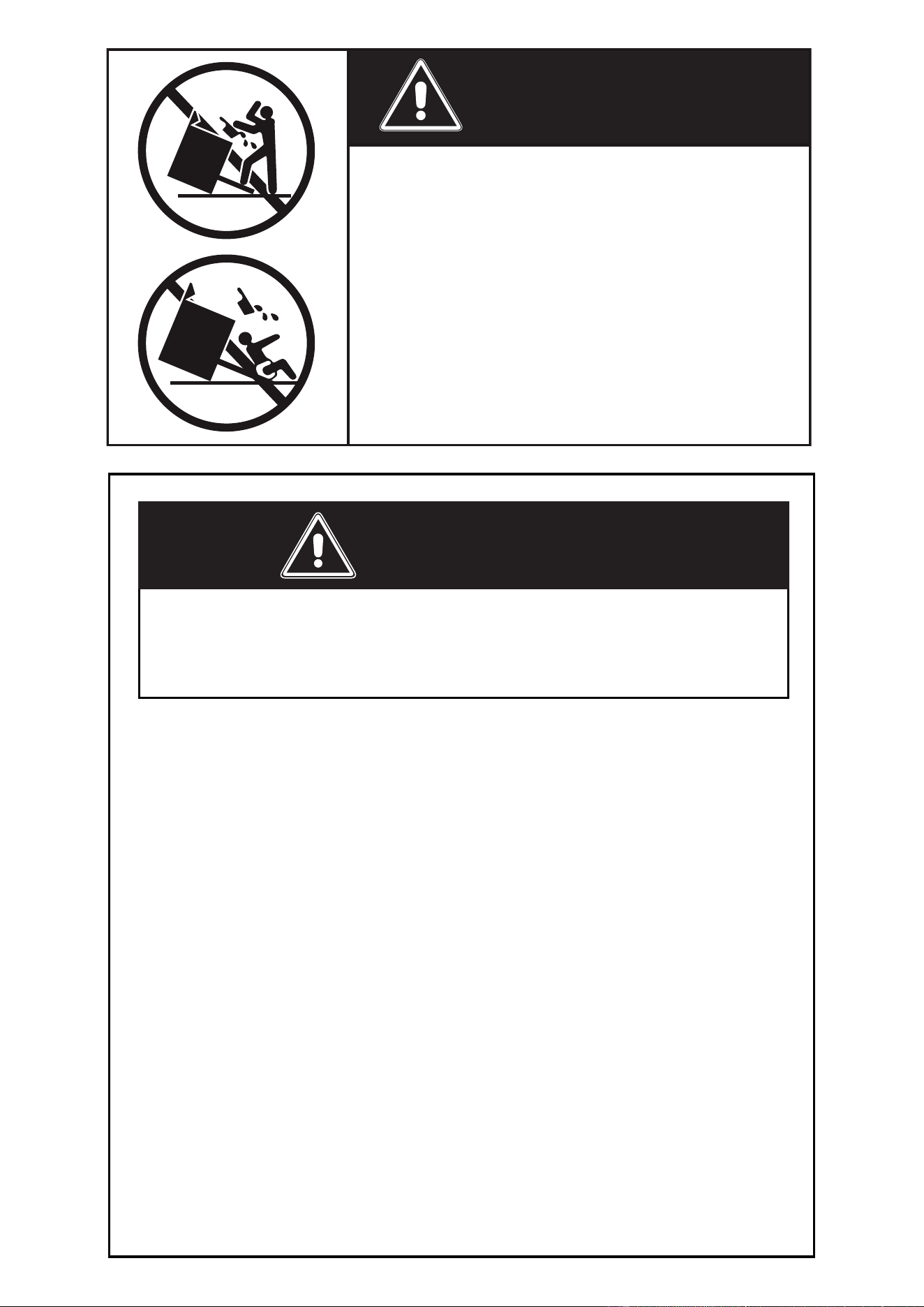
Toreducetheriskoftippingtheappliance,
theappliancemustbesecuredbyproperly
installed anti-tip device packed with the
appliance.
• ALL RANGES CAN TIP
• INJURY TO PERSONS COULD RESULT
• INSTALL ANTI-TIP DEVICE PACKED
WITH RANGE
• SEE INSTALLATION INSTRUCTIONS
– Donotstoreorusegasolineorotherammablevaporsand
liquids in the vicinity of this or any other appliance.
– NEVER use this appliance as a space heater to heat or warm
theroom.Doingsomayresultincarbonmonoxidepoiso-
ningandoverheatingoftheappliance.
– WHAT TO DO IF YOU SMELL GAS:
• Donottrytolightanyappliance.
• Do not touch any electrical switch.
• Donotuseanyphoneinyourbuilding.
• lmmediately call your gas supplier from a neighbor’s
phone.Followthegassupplier’sinstructions.
• lfyoucannotreachyourgassupplier,calltheredepart-
ment.
– Installationandservice must be performed by a qualied
installer,serviceagency,orthegassupplier.
Iftheinformationinthismanualisnotfollowedexactly,
a
re
or
explosion
may
result
causing
property
damage,
personal
injury,ordeath.
WARNING !
3
Thisapplianceisdesignedandmanufacturedsolelyforthecookingofdomestic(household)food
andinnotsuitableforanynonedomesticapplicationandthereforeshouldnotbeusedinacom-
mercialenvironmement.
Theappliancewarrantywillbevoidiftheapplianceisusedwithinanonedomesticenvironmement
i.e.asemicommercial,commercialorcommunalenvironment.
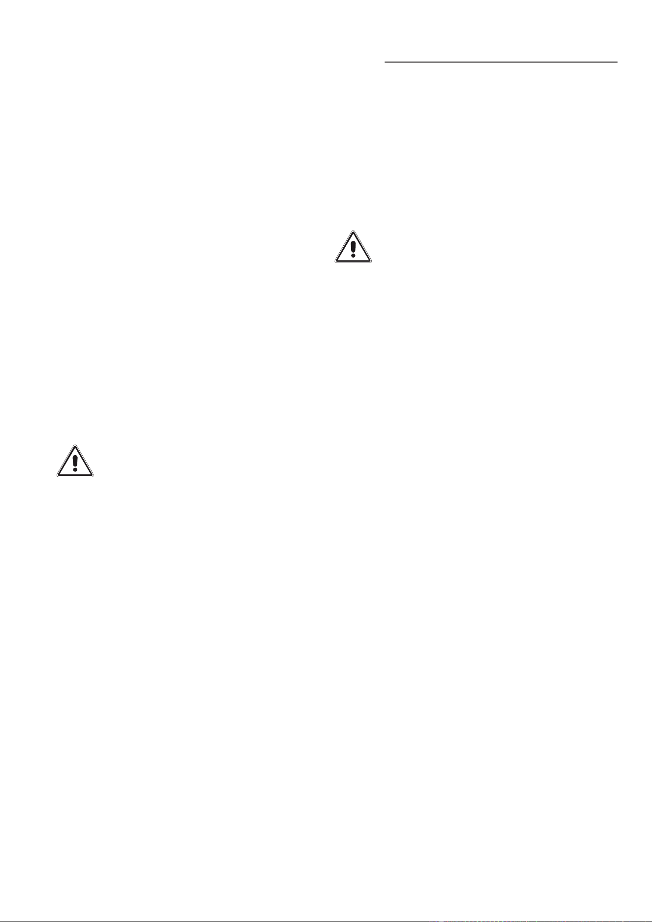
CONVERSIONLABEL
DATAPLATE
TheGovernorofCaliforniaisrequiredtopublishalistofsubstancesknowntothestateofCalifor-
niatocausecancerorreproductiveharmandrequiresbusinessestowarncustomersofpotential
exposurestosuchsubstances.
WARNING!: Gas appliances contain or produce substances which can cause death or serious
illnessandwhichareknowntotheStateofCaliforniatocausecancer,birthdefectsorotherrepro-
ductiveharm.Toreducetheriskfromsubstancesinfuelorfromfuelcombustion,makesurethis
applianceisinstalled,operated,andmaintainedaccordingtothemanufacturer’sinstructions.
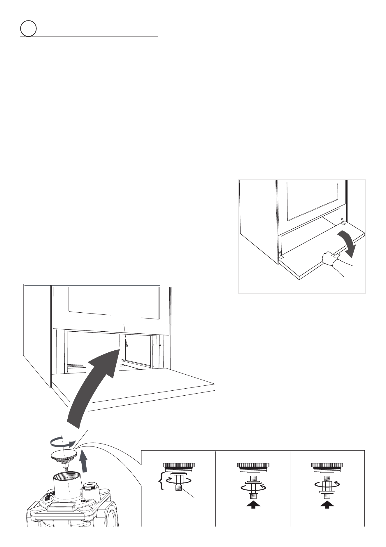
The product data plate is
attachedinsidethebottom
pivotingpanel.
4
INSTALLATION INSTRUCTIONS
WARNING!
THIS APPLIANCE MUST BE INSTALLED BY A QUALIFIED INSTALLER.
Improperinstallation,adjustment,alteration,services,ormaintenancecancauseinjuryorpropertydamage.Consultaquali-
edinstaller,serviceagent,orthegassupplier.
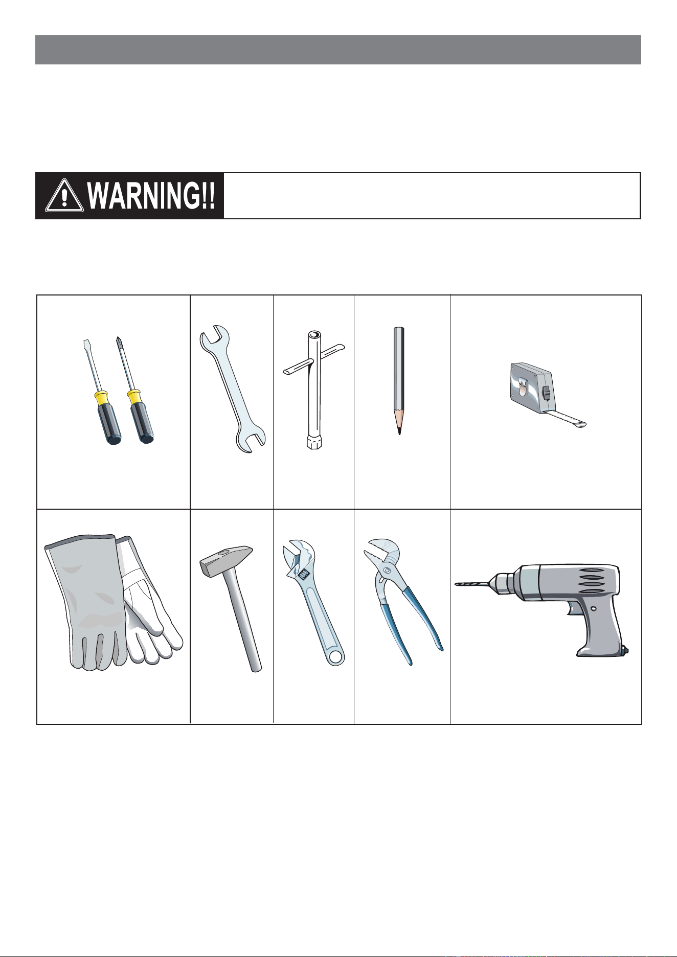
Screwdriver 2 - Wrench
T-handle
wrench
Tape
measurePencil
Adjustable
pliers
Adjustable
wrench
Suitable protective
gloves
Drill
Hammer
TOOLS NEEDED FOR INSTALLATION (NOT SUPPLIED WITH THE APPLIANCE)
IMPORTANT:Theuseofsuitableprotectiveclothing/glovesis
recommendedwhenhandling,installingofthisappliance.
5
GENERAL INFORMATION
1. Installation mustconform with local codes or, in the absen-
ceoflocal codes, with the National Fuel Gas Code,ANSI
Z223.1/NFPA54
-LatestEdition,CAN/CGA-B149.1orCAN/
CGA-B149.2.
2. Installationinmanufactured(mobile)home:installationmust
conform with the Manufactured Home Construction and
Safety Standard, Title 24 CFR, Part 3280 [formerly the
FederalStandardforMobileHomeConstructionandSa-
fety, Title 24, HUD (Part 280)] or, when such standard is
notapplicable,theStandardforManufactured Home Instal-
lations,ANSI/NCSBCSA225.1, or with local codes where
applicable.
3. Installation in Recreational Park Trailers: installation must
conformwithstateorothercodesor,intheabsenceofsuch
codes, with the Standard for Recreational Park Trailers,
ANSIA119.5.
4. Toeliminateriskofburnsorrebyreachingoverheatedsur-
face units, cabinet storage located above the surface units
shouldbeavoided.
5. Aircurtainorotheroverheadrangehoods,whichoperateby
blowingadownwardairowontoarange,shallnotbeused
inconjunctionwithgasrangesotherthanwhenthehoodand
rangehavebeendesigned,testedandlistedbyanindepen-
denttestlaboratoryforuseincombination.
6.
WARNING!!
Thisapplianceshallnotbeusedforspaceheating.This
informationisbasedonsafetyconsiderations.
7. AlIopeningsinthewallbehindtheapplianceandintheoor
undertheapplianceshallbesealed.
8. Keepapplianceareaclearandfreefromcombustiblemate-
rials,gasoline,andotherammablevapors.
9. Donotobstructtheowofcombustionandventilationair.
10. Disconnecttheelectricalsupplytotheappliancebeforeser-
vicing.
11. Whenremovingapplianceforcleaningand/orservice;
A. Shutoffgasatmainsupply.
B. DisconnectACpowersupply.
C. Disconnectgaslinetotheinletpipe.
D. Carefullyremovetherangebypullingoutward.
CAUTION:Rangeisheavy;usecareinhandling.
12.
Electrical Requirement
Electrical installation should comply with national and local
codes.
13.
Air Supply and Ventilation
Theinstallermustreferstolocal/nationalcodes.
14.
Gas Manifold Pressure
Naturalgas-4.0”W.C.P.
LP/Propane-11.0”W.C.P.
15. Themisuseofovendoor(e.g.stepping,sitting,orleaningon
them)canresultinpotentialhazardsand/orinjuries.
WARNING!!
ELECTRICAL GROUNDING INSTRUCTIONS
Therangemustbeelectricallygroundedinaccordancewith
localcodesor,intheabsenceoflocalcodes,withtheNatio-
nalElectricalCode,ANSI/NFPANo.70-latestedition,inCana-
da Canadian Electrical Code.
InstallationshouldbemadebyaIicensedelectrician.
FORPERSONALSAFETY,THISAPPLIANCEMUSTBEPRO-
PERLY GROUNDED.
Ifanexternalelectricalsourceisutilized,theinstallationmustbe
electrically grounded in accordance with local codes or, in the
absenceoflocal codes,withthenationalElectricalCode,ANSI/
NFPA70.
This appliance is equipped with a three-prong grounding plug
(NEMA 5-15P) for your protection against shock hazard and
shouldbepluggeddirectlyintoaproperlygroundedsocket.
Do not under any circumstances cut or remove the third
(ground)prongfromthepowerplug.
REPLACEMENT PARTS
Onlyauthorizedreplacementpartsmaybeusedinperformingser-
viceontherange.Replacementpartsare availablefromfactory
authorizedpartsdistributors.Contactthenearestpartsdistributor
inyourarea.
16. Wheninstallingorremovingtherangeforservice,arollinglift
jackshouldbeused.Donotpushagainstanyoftheedgesof
therangeinanattempttoslideitintooroutoftheinstallation.
Pushingorpullingarange(ratherthanusingaliftjack)also
increases the possibility of bending the leg spindles or the
internalcouplingconnectors.
6
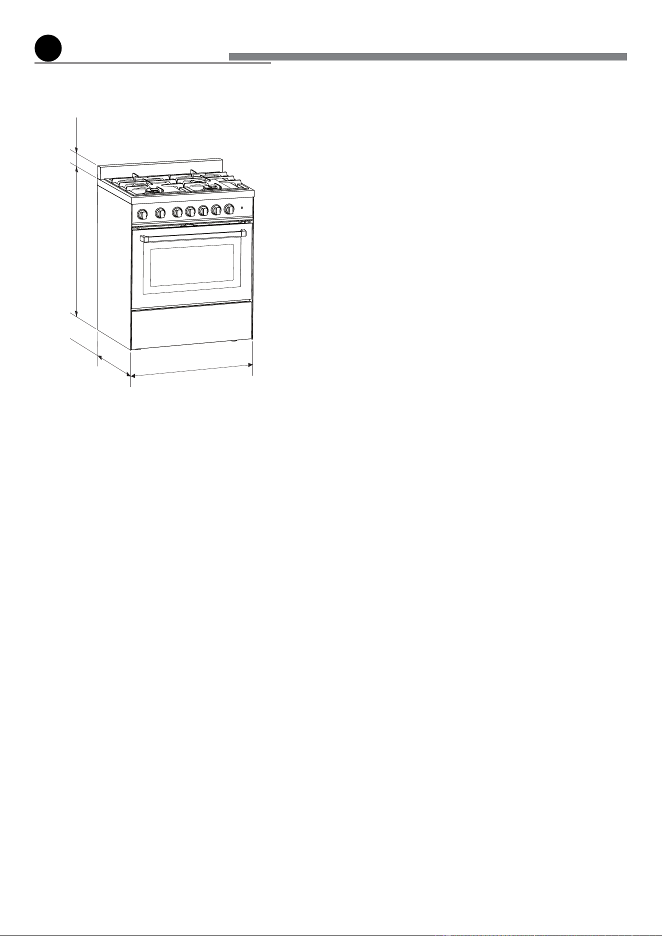
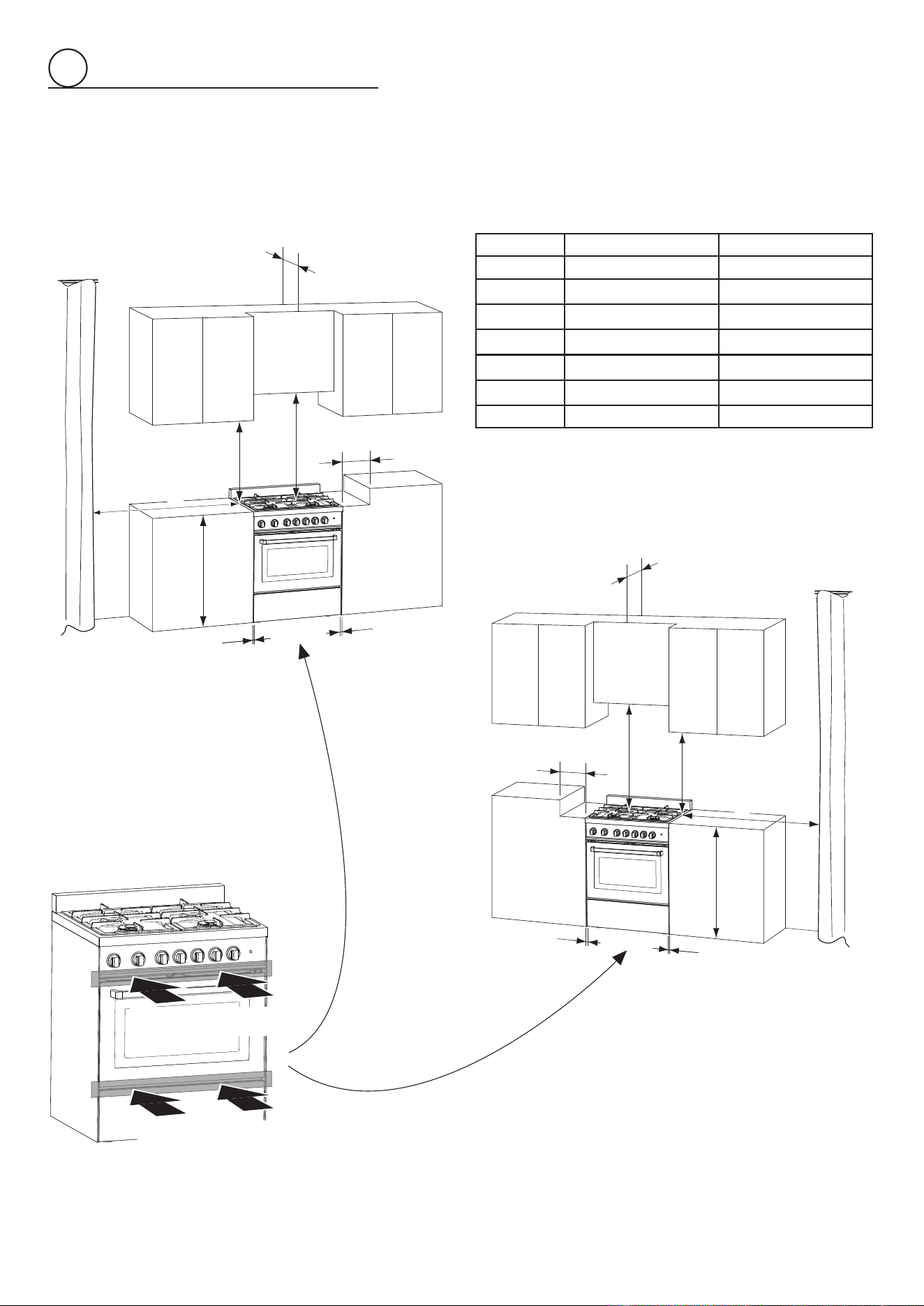
PROXIMITY TO SIDE CABINETS
1. Thisrangemaybeinstalleddirectlyadjacenttoexisting36”(914mm)
highbasecabinets.
Rangedimensions:
• width:29”7/8(759mm)
• depth:24”13/64(614.9mm)
• height (without backguard): MIN 35” 21/32 (905.5 mm) - MAX 36”
11/32(923mm)
• backguard(height):3”(76mm)
Gaslineopening:Wall-37/64”(14.5mm)fromtherightsidetocentre
ofrange;from5”7/16(138mm)to6”1/8(155.5mm)[dependingonfeet
regulation]fromtheoor.
Grounded outlet:The electric cord with3-prong ground plug (NEMA
5-15P)hasalengthof72”(1830mm).Groundedoutletshouldbeloca-
ted37/64”(14.5mm)fromtheleftsidetocentreofrange;from5”7/16
(138mm)to6”1/8(155.5mm)[dependingonfeetregulation]fromthe
oor.
2. TherangeCANNOTbeinstalleddirectlyadjacenttosidewalls,tallcabi-
nets,tallappliances,orothersideverticalsurfacesabove36”(914mm)
high.
Theremustbeaminimumof11”13/16(300mm)sideclearancefromthe
rangetosuchcombustiblesurfacesTOTHELEFTorTOTHERIGHT
abovethe36”(914mm)highcountertop.
IMPORTANT:Oneside(leftorright)abovethe36”(914mm)high
countertopmustalwaysbekeptclear.
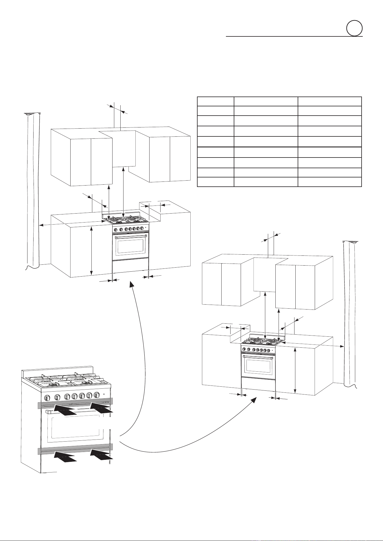
Island installation: Theremustbeaminimumof12”(305mm)clearan-
cefromtherear ofthebackguardto suchcombustiblesurfaceon the
backoftherangeabovethe36”(914mm)highcountertop.
3. Themaximumuppercabinetdepthrecommendedis13”(330mm).Wall
cabinetabovetherangemustbeaminimumof30”(762mm)abovethe
countertopforawidthofminimum30”(762mm):ithastobecentered
withtherange.Sidewallcabinetsabovetherangemustbeaminimum
of18”(457mm)abovethecountertop.
installation
1
Fig. 1.1
3”
(76mm)
MIN35”21/32(905.5mm)
MAX36”11/32(923mm)
24”
13/64
(614.9
mm)
29”
7/8
(759
mm)
7
A
A
B
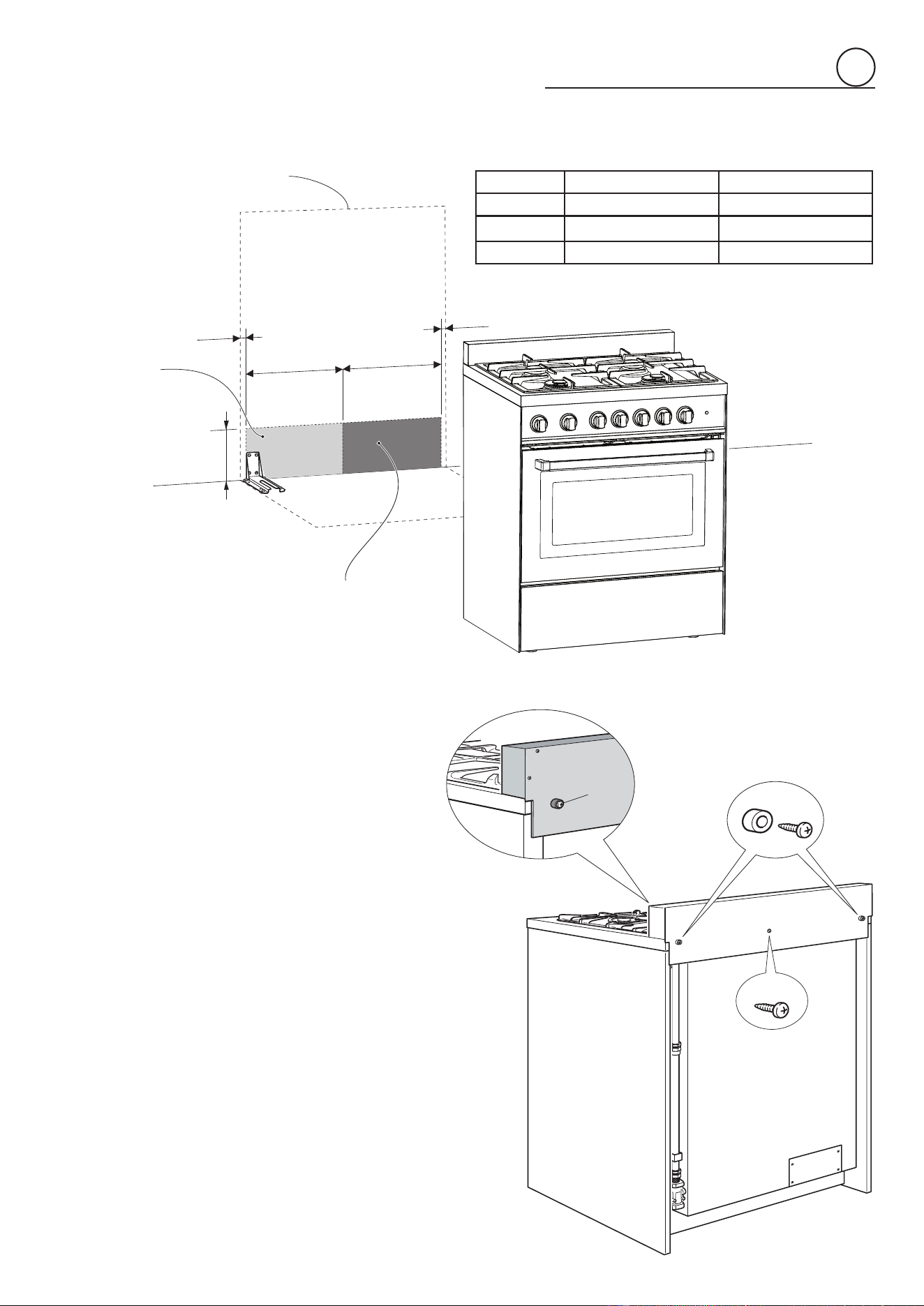
ASSEMBLING THE BACKGUARD
Itismandatorytoinstallthebackguard.
Assemblethebackguardasshowningure1.3:
• Screwthe2screws“A”interposingthespacers.
• Screwthecentralscrew“B”.
1
Fig. 1.3
GAS AND ELECTRIC CONNECTION
Fig. 1.2
Dottedlineshowingtheposition
oftherangewheninstalled
Areafor
ELECTRICAL
connection
Areafor
GASconnection
B
A
B
C
C
Ref. inch mm
A 5”7/16-6”1/8(*) 138-155.5(*)
B 14”3/8 365
C 37/64” 14.5
(*):Dependingonfeetregulation
8
B
G
E
D
C
F
A
A
B
C
E
D
F
G
A
A
PROXIMITY TO SIDE CABINETS
STANDARD INSTALLATION
Fig. 1.4b
Fig. 1.4a
OVEN VENT
Ref. inch mm
A 0” 0
B 36” 914
C 11”13/16 300
D 30”minimum 762minimum
E 18”minimum 457minimum
F 13”maximum 330maximum
G 20”minimum 500minimum
OVEN VENT
1
9
PROXIMITY TO SIDE CABINETS
ISLAND INSTALLATION
A
A
B
G
E
D
F
C
H
A
A
B
G
E
D
F
C
H
Fig. 1.5b
Fig. 1.5a
OVEN VENT
Ref. inch mm
A 0” 0
B 36” 914
C 11”13/16 300
D 30”minimum 762minimum
E 18”minimum 457minimum
F 13”maximum 330maximum
G 20”minimum 500minimum
H 12”minimum 305minimum
OVEN VENT
1
10
1
YOU MUST USE STABILITY
ANTI TIP BRACKET TO
PREVENT UNIT FROM
TIPPING.
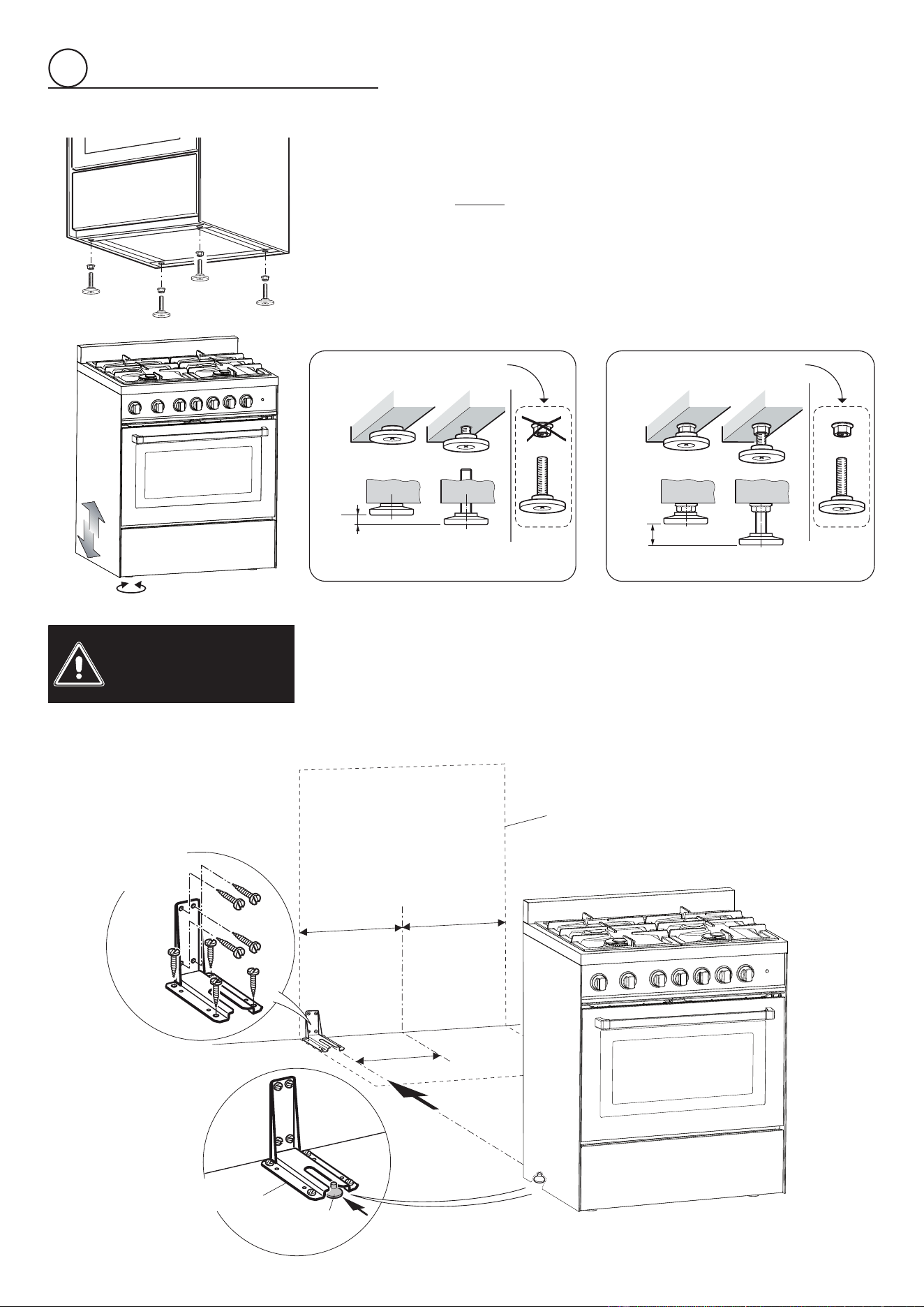
ANTI-TIP STABILITY DEVICE INSTALLATION INSTRUCTIONS
1. Theanti-tipbrackethastobeattachedasshownongurebelow(onlyrearleftside),
ithastobexedontheoorORontherearwallbyno.4(four)suitablescrews(not
supplied).Alternativelytheanti-tipbracketcanalsobexedontheoorANDonthe
rearwallbyno.8(eight)suitablescrews(notsupplied).
2. Afterxingtheanti-tipbracket,sliderangeintoplace.Besuretherearleftfootslides
undertheanti-tipbracketattached.
LEVELLING THE RANGE
Therangeisequippedwith4LEVELLINGFEETandmaybelevelledbyscrewingor
unscrewingthefeet(gs.1.6-1.7).
Itisimportanttoobservethedirectionsofgures1.6,1.8a,1.8b.
Fig. 1.8bFig. 1.8a
Fig. 1.7
Fig. 1.6
Suppliedwiththerange
inaseparatekit
Suppliedwiththerange
inaseparatekit
0”
0mm
+5/16”
+8mm
+5/16”
+8mm
+11/16”
+17.5mm
Fig. 1.9
Dotted line showing the position
oftherangewheninstalled
ANTI-TIPSTABILITY
DEVICEFIXING
Anti-tipstability
device
Rearleft
feetofrange
3”
15/64
(82mm)
=
=
11
1
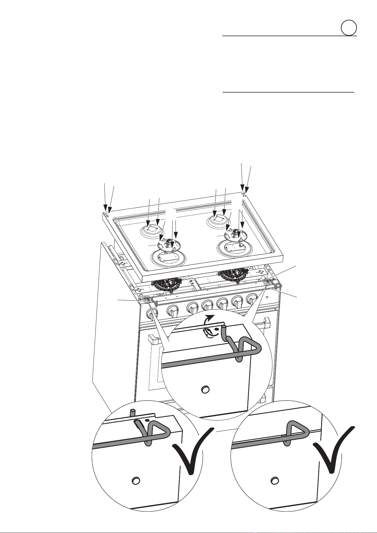
INSTALLING THE COOKTOP FRONT GUARD
Toincreasetheclearancebetweenthefrontedgeofthecooktopandtheburnersitispossibletoinstallthecooktopfrontguardsupplied
withtheappliance.
IMPORTANT:Toinstall/removetheguarditisnecessarytoremovethecooktop.
Attemptingtoinstall/removetheguardwithoutdisassemblingthecooktopwillresultinpermanentdamagetotheappliance.
Installthefrontguardasshowningure1.10:
1. Removethebackguard.
2. Removethepansupports,theburnercapsandtheamespreaders.
3. Unscrewcooktopxingscrews(“A”ingurebelow).
4. Removethedualburnerinneramespreader(“B”ingurebelow).
5. Removethecooktop(keepattentionnottodamagethegasketsttedabovetheburnercups-belowthecooktop).
6. Installthefrontguard“C”byinsertingthewireterminalsintotheproperholesabovethecontrolpanel(“D”ingurebelow).
7. Reassemblethecooktopandtheothercomponents(stepsfrom5to1).
Payspecialattentiontothegasketsttedabovetheburnercups
(belowthecooktop);iftheyaredamagedtheyshallbereplaced.
Fig. 1.10
A
A
A
A
A
A
B
B
C
D
D
12
gasconnection
2
2.PressureRegulator:
a. Allheavyduty,commercialtypecookingequipmentmusthaveapressureregulator
ontheincomingservicelineforsafeandefcientoperation,sinceservicepressure
mayuctuatewithlocaldemand.
Beforeinstallingtheregulatormountthe1/2”NPT(conical)maleconnectortothe
regulator(seepicture2.2).
Gasketsuppliedhastobeplacedbetween1/2”NPT(conical)connector/extension
pipemalepipetting(seepicture2.3).
Theregulatorsuppliedwiththisrangemustbeinstalledbeforeanygasconnections
aremade.
Usesuppliedpressureregulatoronly.
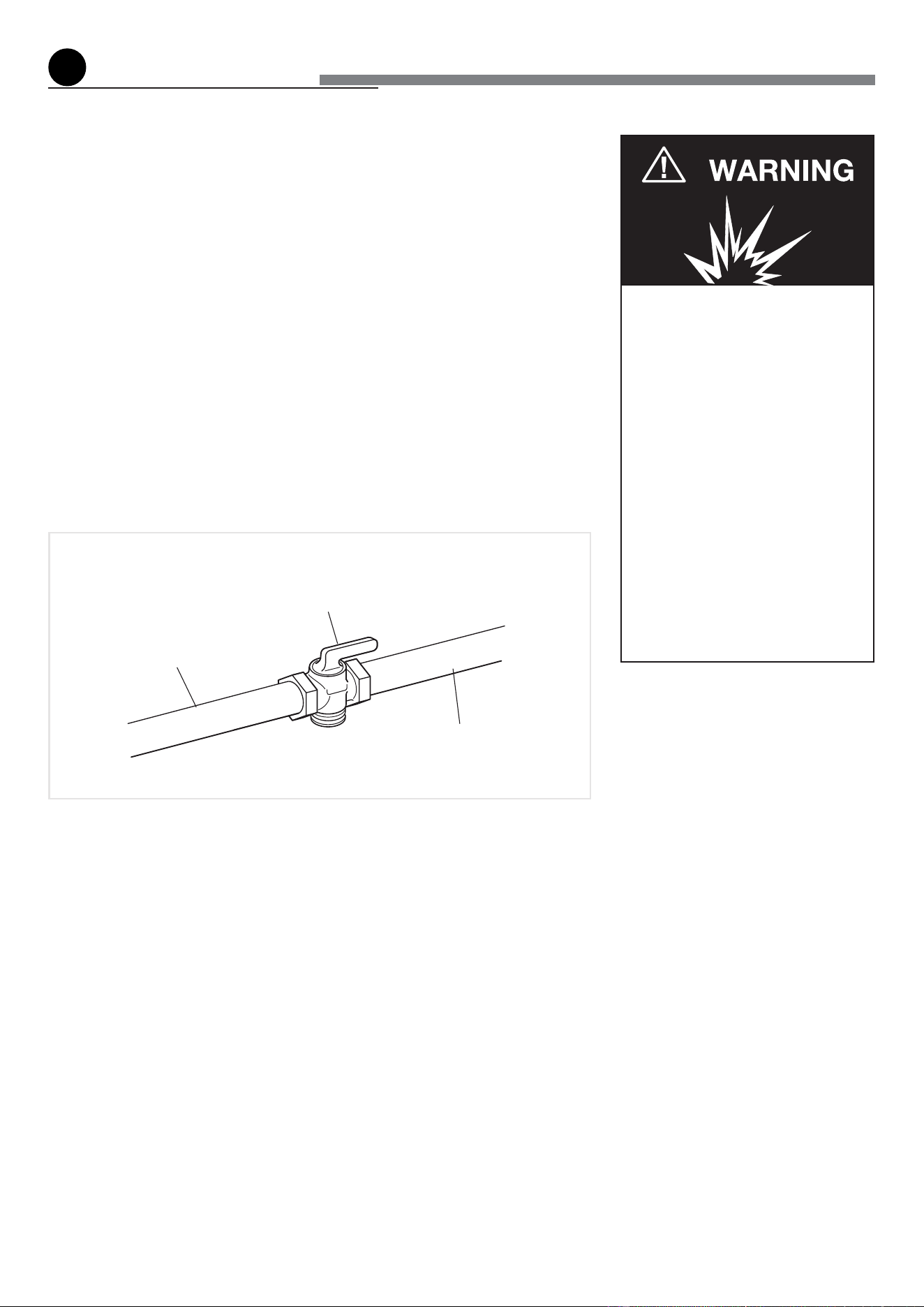
Gas supply line
Shuto valve
“open” position
To range
Explosion Hazard
Use a new CSA or UL approved
gas supply line.
Install a shut-off valve.
Securely tighten all gas connec-
tions.
If connected to LP, have a quali-
fied person make sure gas pres-
sure does not exceed 14" water
column.
Examples of a qualified person
include licensed heating per-
sonnel, authorized gas compa-
ny personnel, and authorized
service personnel.
Failure to do so can result in
death, explosion, or fire.
Fig. 2.1
Allgasconnectionsmustbemadeaccordingtonationalandlocalcodes.Thisgassupply
(service)linemustbethesamesizeorgreaterthantheinletlineoftheappliance.Sea-
lantonallpipejointsmustberesistanttotheactionofLP/Propanegas.
TherangeisequippedfortheusewithNATURALgas.Itisdesign-certiedbyCSAInter-
nationalforNATURALandL.P.gaseswithappropriateconversion.
Themodel/serialratingplate,locatedinsidethebottompivotingpanel,hasinformation
onthetypeofgasthatcanbeused.Ifthisinformationdoesnotagreewiththetypeof
gasavailable, check withthe localgas supplier.See page from16 to21 for L.P.gas
conversioninstructions.
1.ManualShut-offValve(g:2.1):
Amanualshut-offvalvemustbeinstalledinanaccessiblelocationinthegaslineexternal
totheapplianceforthepurposeofturningonorshuttingoffgastotheappliance(InMas-
sachusettssuchshutoffdevicesshouldbeapprovedbytheBoardofStateExaminersof
Plumbers&GasFitters).
Thisvalveshouldbelocatedinthesameroomastherangeandshouldbeinalocation
thatallowseaseofopeningandclosing(inapositionwhereitcanbereachedquicklyin
theeventofanemergency).
Donotblockaccesstotheshutoffvalve.Thevalveisforturningonorshuttingoffgas
totheappliance.
13
2
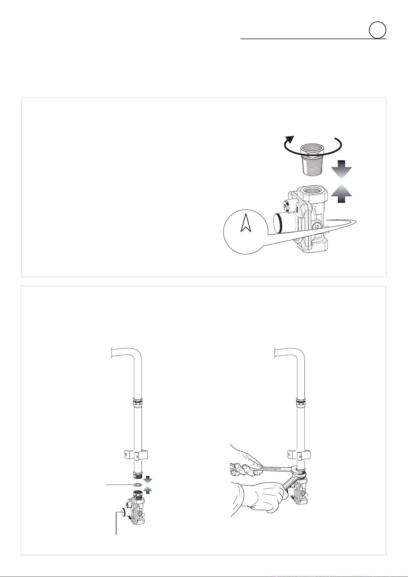
LOCK
Arrow
PRESSURE REGULATOR INSTALLATION
STEP1
Mountthe1/2”NPT(conical)maleconnectortothepressureregulatorand
tightenbyusingawrench.
Donotovertightentheconnector.
Overtighteningmaycrackregulator.
STEP2
Assemblethe1/2”NPTconnector+pressureregulatorgrouptotheextensionpipeinterposingthegasketsupplied.
Theregulatorcovermustbeorientedtowardthefrontsideoftherange.
IMPORTANT:usetwowrenchestotightentheconnection.
Fig. 2.3
Fig. 2.2
Regulatorcover
Gasket
14
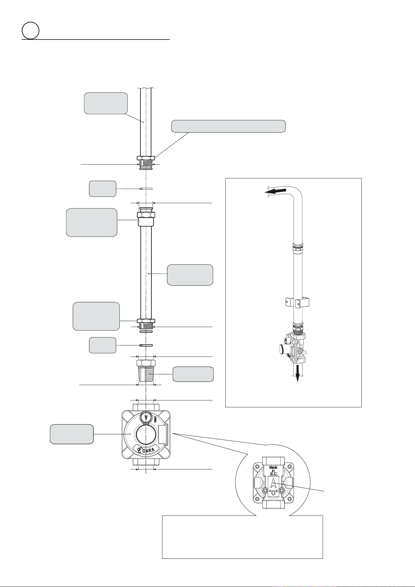
2
Fig. 2.4
GAS CONNECTION SPEFICICATION
Range
manifold
Manifoldmalepipetting
1/2”Gcylindrical
(ISO228-1)male
1/2”Gcylindrical
(ISO228-1)female
Gasket
Extension
pipe female
pipetting
Torange
1/2”Gcylindrical
(ISO228-1)female
Extension
pipe
1/2”Gcylindrical
(ISO228-1)male
Extension
pipe male
pipetting
Gasket
Connector
1/2”NPT(conical)
male
1/2”NPT
female
Pressure
regulator
1/2”NPT
female
To mains
connection
Arrow
WARNING: Check the right positioning of the gas
regulator.
Thearrowonthebackofthegasregulatormustbe
oriented toward the connector.
15
2
b. Anyconversionrequiredmustbeperformedbyyourdealeroraqualiedlicen-
sedtechnicianorgasservicecompany.Pleaseprovidetheservicepersonwith
thismanualbeforeworkisstartedontherange.(Gasconversionsarethere-
sponsibilityofthedealerorenduser.)
c. ThisrangecanbeusedwithNATURALorLP/PROPANEgas.Itisshippedfrom
thefactoryadjustedforusewithNATURALgas.
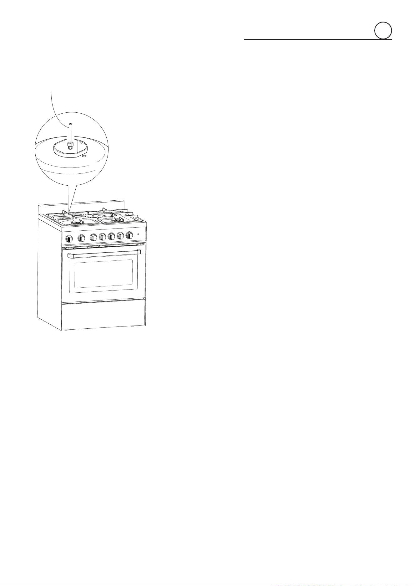
d. Manifold pressureshould be checked with a manometerandby operating as
belowdetailed:
• Removetheinjectorfromtherearleft(orrearright)burnerandmountthe
proper test point adapter which is available from theAfter-Sales Service
(seesidegureandthe“OPERATIONSTOBEPERFORMEDWHENSUB-
STITUTINGTHEINJECTORSOFTHECOOKTOPBURNERS”chapter).
• Turntherearleft(orrearright)burnercontrolknobtothemaximumposi-
tion.
• Presstheknobandkeepingitpressedcheckthemanifoldpressurewitha
manometer;NATURALgasrequires4.0”W.C.P.andLP/PROPANErequires
11.0”W.C.P.
• Incominglinepressureupstreamfromtheregulatormustbe1”W.C.P.hi-
gherthanthemanifoldpressureinordertochecktheregulator.
• Theregulatorusedonthisrangecanwithstandamaximuminputpressure
of1/2PSI(14.0”W.C.P).Ifthelinepressureisinexcessofthatamount,a
stepdownregulatorwillberequired.
e. Theappliance,itsindividualshut-offvalve,andpressureregulatormustbedi-
sconnectedfrom thegas supplypiping system duringany pressuretesting of
thatsystematpressuresinexcessof1/2PSI(3.5kPa).
f. Theappliancemustbeisolatedfromthegassupplypipingsystembyclosingits
individualmanualshut-offvalveduringanypressuretestingof thegassupply
pipingsystemattestpressureequaltoorlessthan1/2PSI(3.5kPa).
3.FlexibleConnections:
Iflocalcodespermit,CSAorULdesign-certied,exiblemetalapplianceconnector
isrecommendedforconnectingthisrangetothegassupplyline.DoNotkinkorda-
magetheexibleconnectorwhenmovingtherange.Thepressureregulatorhas1/2”
NPTfemalepipethreads.Youwillneedtodeterminethettingsrequired,depending
onthesizeofyourgassupplyline,exiblemetalconnectorandshutoffvalve.
4.RigidPipeConnections:
Ifrigidpipeisusedasagassupplyline,acombinationofpipettingsmustbeusedto
obtainanin-lineconnectiontotherange.Allstrainsmustberemovedfromthesupply
andfuellinessorangewillbelevelandinline.
• Usejointcompoundsandgasketsthatareresistanttoactionofnaturalorpropa-
negasonallmalepipethreads.
• Donotovertightengasttingwhenattachingtopressureregulator.Overtighte-
ningmaycrackregulator.
5.LeakTesting:
IMPORTANT:Leaktestingoftheapplianceshallbeconductedasfollows:
• Afternalgasconnectionismade,turnonmanualgasvalveandtestallcon-
nectionsin gassupplypiping andappliance forgas leakswitha soapywater
solution.Duringthistestallappliancegasvalveshavetobeclosed.
• Inordertoavoidpropertydamageorseriouspersonalinjury,neveruseaIighted
match.Ifaleakispresent,tightenjointorunscrew,applymorejointcompound,
tightenagainandretestconnectionforleak.
Fig. 2.5
TESTPOINTADAPTER
The Test Point adapter is available from the
After-SalesService.
16
Pressure
regulator
1
2
NATURAL GAS
REGULATION
LP/PROPANE
REGULATION
A
REGULATOR COVER
2
CONVERSION TOLP/PROPANE GAS (OR CONVERSION BACK TOTHE
ORIGINAL GAS - NATURAL GAS)
Everyrangeisprovidedwithasetofinjectorsforthevarioustypesofgas.
Selecttheinjectorstobereplacedaccordingtothe“INJECTORSTABLE”.
Thenozzlediameters,expressedinhundredthsofamillimetre,aremarkedonthebodyofeachinjector.
CAUTION:Savetheoricesremovedfromtheapplianceforfutureuse.
SETTING THE PRESSURE REGULATOR
Thepressure regulatorisaccessible byopening the pivotingpanel (g.2.6); the pressureregulator is
positionedontherearrightsideoftherange(g.2.7).
Tosetthepressureregulator(g.2.7):
1. Unscrewtheregulatorcover.
2. Unscrewthe“A”component,reverseandscrewitaccordingtotheLP/PROPANE(orNATURALGAS)
regulation.
Fig. 2.6
Fig. 2.7
17
2
OPERATIONS TO BE PERFORMED WHEN SUBSTITUTING THE
INJECTORS OF THE COOKTOP BURNERS
• Removethepansupports,theburnercapsandtheamespreaders.
• Dualburneronly(g.2.9):Unscrewtheno.3xingscrews“A”andremovetheinner
crownamespreader“B”;thenunscrewtheno.2xingscrews“C”andremovethe
coverplate“D”.
• Usingawrenchsubstitutethenozzleinjectors“J
1
”,“J
2
”and“J
3
”(gs.2.8,2.9)with
thosemostsuitableforthekindofgasforwhichitistobeused.
• Dualburneronly(g.2.9):
Ret
thecoverplate“D”andscrewtheno.2xingscrews
“C”;thenrettheinnercrownamespreader“B”andscrewtheno.3xingscrews“A”
• Rettheamespreaders,theburnercapsandthepansupports.
Theburnersareconceivedinsuchawaysoasnottorequiretheregulationofthe
primary air.
SECOND ORIFICE
DEUXIEME ORIFICE
A
A
A
B
C
C
D
J
2
J
3
Fig. 2.9
J
1
Fig. 2.8
SEMI-RAPID BURNER
DUAL BURNER
INJECTORS TABLE
NOMINAL
POWER
REDUCED
POWER
LP/PROPANE
11”W.C.P.
NATURAL GAS
4”W.C.P.
BURNERS BTU/hr BTU/hr
Øinjector
[1/100mm]
Øinjector
[1/100mm]
Semirapid(SR) 8000 1500 85 139
Dual(D)
Innercrown 2100 1000
42(*)
115(**)
70(*)
200(**)
Inner&outercrown 17000 6500
Ovenburner 14000 2400 109 190
Broilburner 11000 - 100 170
(*) innercrown(“J
2
”ingure2.9)
(**) outercrown(“J
3
”ingure2.9)
18
Fig. 2.10
R
1
Regulationscrew(Semirapidburner)
R
2
Regulationscrew(Innercrownofdualburner)
R
3
Regulationscrew(Outercrownofdualburner)
R
1
R
3
R
2
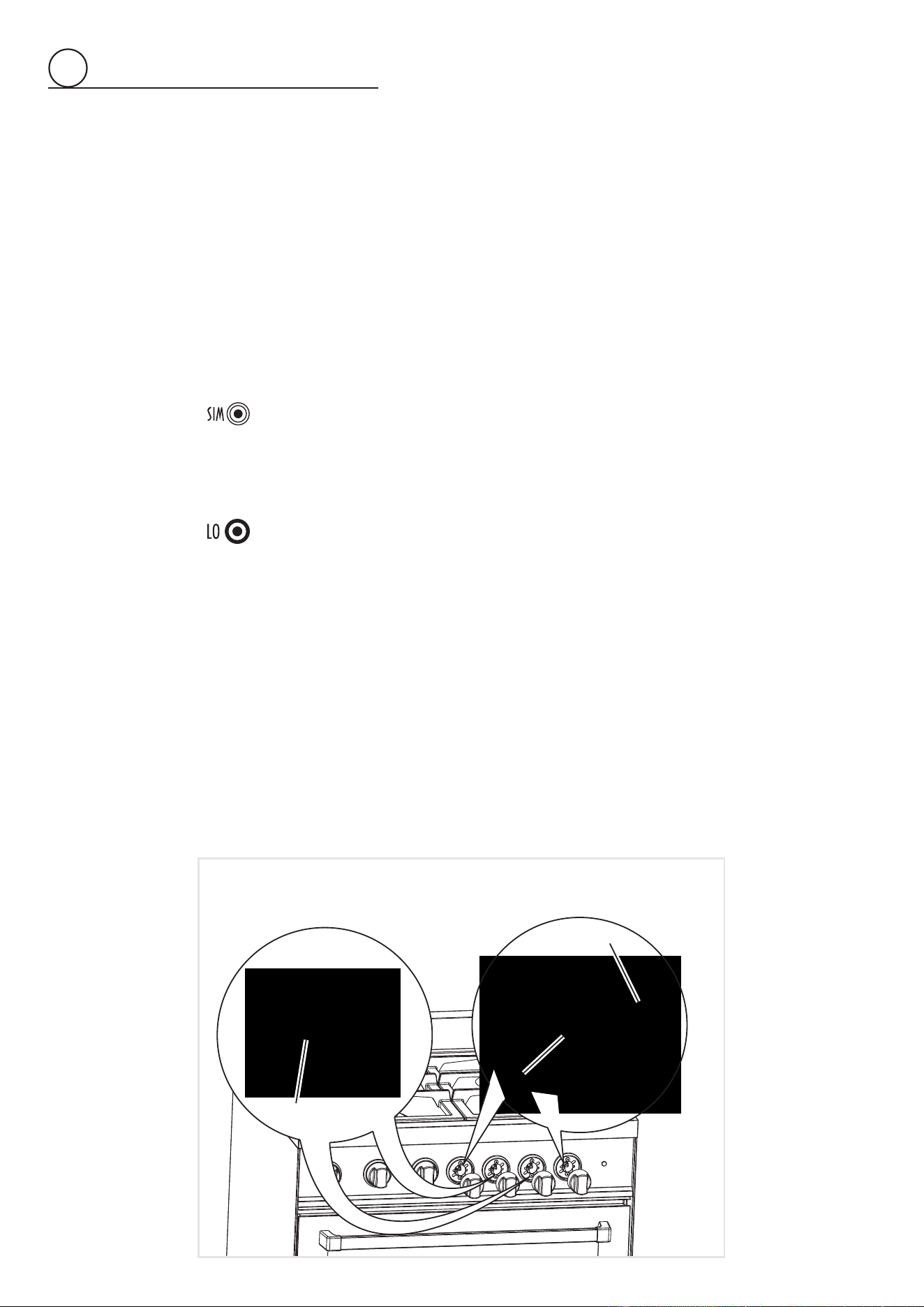
SETTING THE BURNER MINIMUM OF THE COOKTOP BURNERS
Whenswitchingfromonetypeofgastoanother,theminimumowratemustalsobecor-
rect:theameshouldnotgooutevenwhenpassingsuddenlyfrommaximumtominimum
ame.
Toregulatetheame(g.2.10)followtheinstructionsbelow:
Semirapidburner
• Lighttheburner.
• Setthegasvalveto“
LO”position(minimumrate).
• Removetheknob.
• Withathinscrewdriver,turntheregulationscrew“R
1
”untiladjustmentiscorrect.
InsidecrownofDUALburner
• LighttheDUALburner.
• Setthegasvalveto“
”position(minimumrateofinnercrown).
• Removetheknob
• Withathinscrewdriver,turntheregulationscrew“R
2
”untiladjustmentiscorrect.
OutsidecrownofDUALburner
• LighttheDUALburner.
• Setthegasvalveto“
”position(minimumrateofinnerandoutercrowns).
• Removetheknob.
• Withathinscrewdriver,turntheregulationscrew“R
3
”untiladjustmentiscorrect.
ForLP/PROPANEgas,tightentheadjustmentscrewscompletely.
2
19
2
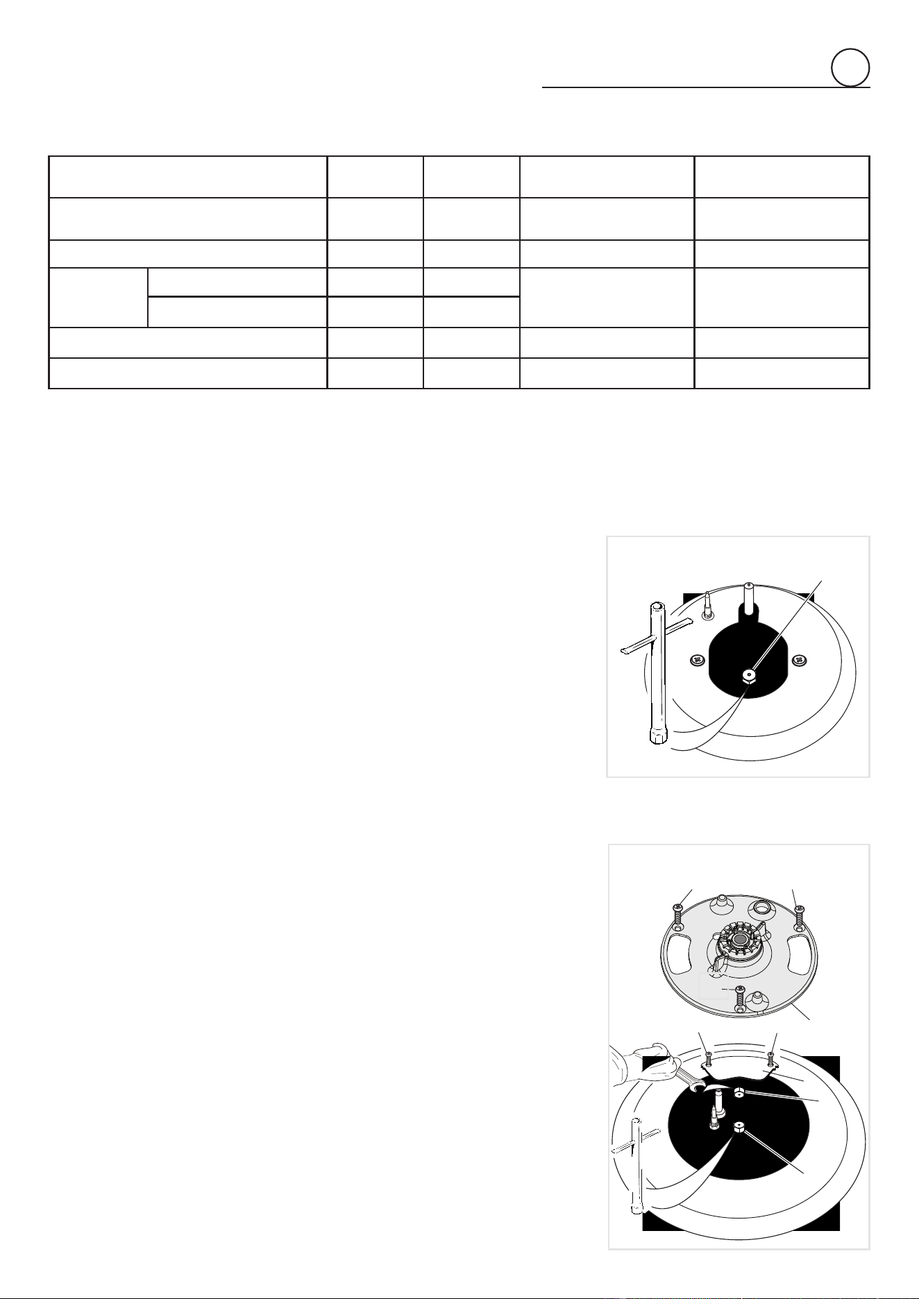
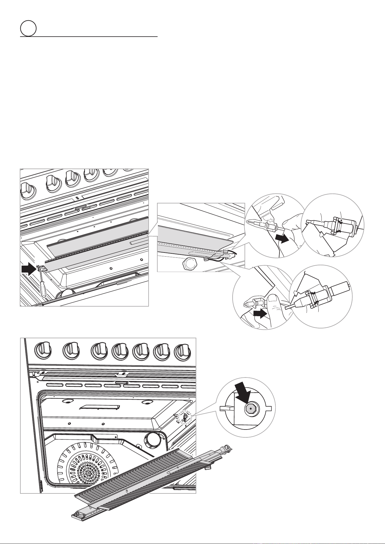
OPERATIONS TO BE EXECUTED FOR THE REPLACEMENT OF
THE INJECTOR OF THE OVEN BURNER
• Liftandremovethelowerpanelinsidetheoven.
• Gentlyunlock,fromtheburner,thesafetyvalveprobe“V”andtheignitionelectrode
“E”(as indicateding. 2.11).Take carenot todamage the probeand the ignition
electrode.
• Unscrewandremovetheburnersecuringscrews“A”(g.2.11).
• Withdrawtheburnerasshowningure2.12.
• Usinga7mmboxspanner,unscrewtheinjector(indicatedbythearrowing.2.12)
andreplaceitwithanewoneselectedinaccordancewiththe“Injectorstable”.
• Then replace the burner and the other components repeating the above steps in
reverseorder.
IMPORTANT:Payspecialattentiontoreplacecorrectlythesafetyvalveprobe
“V”andtheignitionelectrode“E”aspergure2.11.Checkthecorrectopera-
tionofthesafetyvalveandtheignitionelectrode.
Fig. 2.11
Fig. 2.12
E
V
A
Anchorage
clip
Anchorage
clip
E
V
20
2
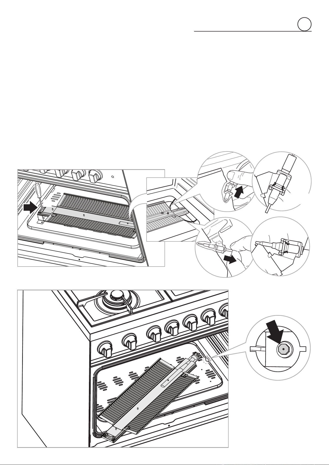
OPERATIONS TO BE EXECUTED FOR THE REPLACEMENT OF
THE INJECTOR OF THE BROIL BURNER
• Gentlyunlock,fromtheburner,thesafetyvalveprobe“V”andtheignitionelectrode
“E”(as indicatedin g.2.13).Take carenottodamagethe probeand theignition
electrode.
• Unscrewandremovetheburnersecuringscrew“A”(g.2.13).
• Withdrawtheburnerasshowningure2.14.
• Usinga7mmboxspanner,unscrewtheinjector(indicatedbythearrowing.2.14)
andreplaceitwithanewoneselectedinaccordancewiththe“Injectorstable”.
• Then replace the burner and the other components repeating the above steps in
reverseorder.
IMPORTANT:Payspecialattentiontoreplacecorrectlythesafetyvalveprobe
“V”andtheignitionelectrode“E”aspergure2.13.Checkthecorrectopera-
tionofthesafetyvalveandtheignitionelectrode.
E
V
A
Anchorage
clip
Anchorage
clip
E
V
Fig. 2.13
Fig. 2.14
21
2
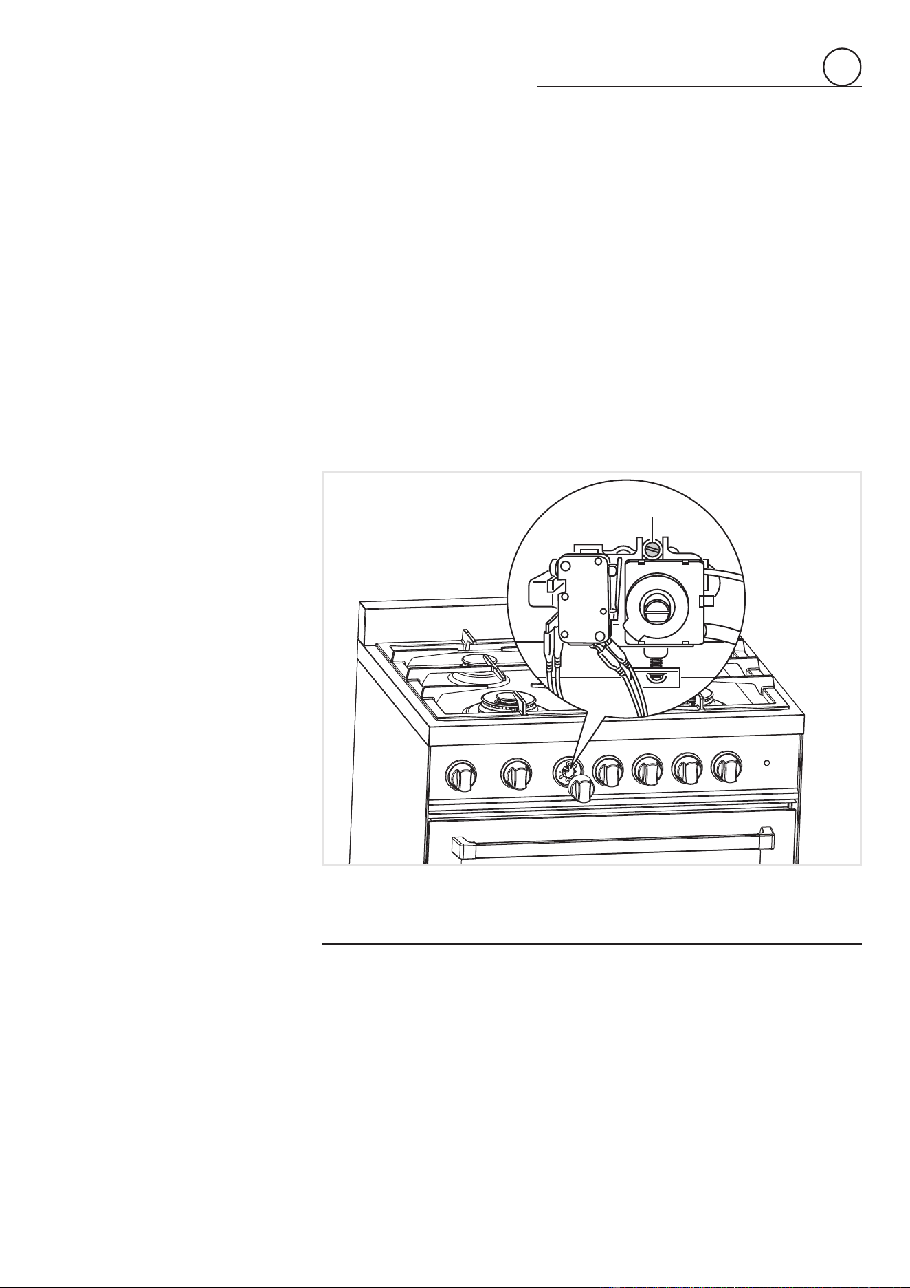
ADJUSTMENT OF THE OVEN BURNER MINIMUM
Thisneedstobedoneonlyfortheovenburner(thebroilisaxedcapacity)byacting
onthethermostatinthefollowingway:
• Turnontheburnerbysettingthethermostatknobonposition“8”(maximum).
• Removetheknobandunscrewtheby-passscrew“G”(g.2.15)aboutthreetimesby
passingasmallatscrewdriver(Ø3mmblade,100mmlength)throughthepanel
opening.
• Re-mounttheknobandlettheovenheatupforabout10minutes,thenbringtheknob
toposition“1”(minimum)tooperatethethermostatby-pass.
• Afterhavingremovedtheknobagainandbeingverycarefulnottoturnthetaprod,
slowlyscrewtheby-passscrews“G”(g.2.15)untilyouobtainaameof3-4mmin
height.Theameshouldnotgooutevenwhenpassingsuddenlyfrommaximumto
minimumame.
N.B.ForLP/PROPANEgastheby-passscrewmustbexedthoroughly.
Fig. 2.15
G
Afterregulationrepeattheoperationsindicatedinparagraph“2.PRESSUREREGULA-
TOR”atpage12and15.
Iftherangehasbeendisconnectedandthenconnectedagaintothegassupplylinerepe-
attheoperationsindicatedinparagraph“5.LEAKTESTING”atpage15.
IMPORTANT:
• AfterconversiontoLP/PROPANEgashasbeencarriedoutafxnearthedataplate
theconversionlabelsuppliedandalsoafxaconversionlabelatpage3ofthisin-
structionmanual.
• Afterconversionbacktotheoriginalgas(NATURALGAS)hasbeencarriedoutre-
move,nearthedataplateandatpage3ofthisinstructionmanual,theLP/PROPANE
conversionlabels.Savethelabelsremovedforfutureuse.
22
electrical connection
3
Ifcodespermitandaseparategroundwireisused,itisrecommendedthataqua-
liedelectriciandeterminethatthegroundpathisadequate.
Checkwithaqualiedelectricianifyouarenotsurewhethertherangeisproperly
grounded.
DoNotgroundtoagaspipe.
A120-volt,60-Hz,AC-only,15-ampere,fusedelectricalsupplyisrequired.
Atime-delayfuseorcircuitbreakerisrecommended.
Itisrecommendedthataseparatecircuitservingonlythisappliancebeprovided.
The outlet must bechecked by a qualied electrician to see if it is wired with correct
polarity.
Thisappliance,wheninstalled,mustbeelectricallygroundedinaccordance withlocal
codes.
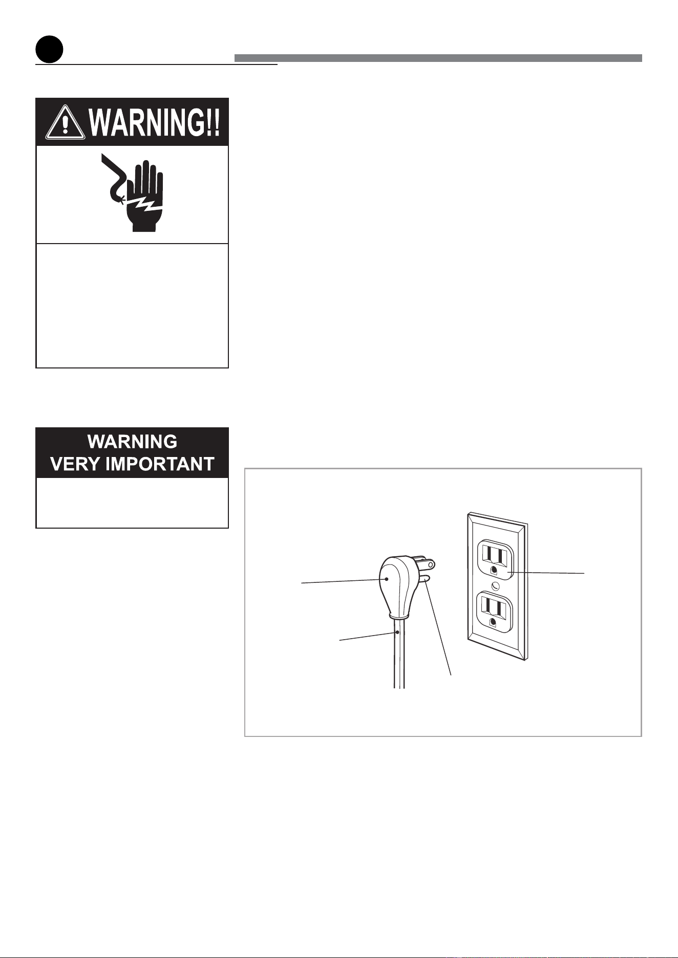
Recommendedgroundmethod
Foryourpersonalsafety,thisrangemustbegrounded.
Thisrangeisequippedwitha3-pronggroundplug.
To minimize possible shock hazard, the cord must be plugged into a mating 3-prong
ground-type outlet, grounded in accordance with the National Electrical Code ANSI/
NFPA70latesteditionandlocalcodesandordinances.
Ifamatingoutletisnotavailable,itisthepersonalresponsibilityandobligationofthecu-
stomertohaveaproperlypolarizedandgrounded,3-prongoutletinstalledbyaqualied
electrician.
Electrical Shock Hazard
Plug into a grounded 3-prong
outlet.
Donotremovegroundprong.
Do not use an adapter.
Failure to follow these instruc-
tionscanresultindeath, re, or
electrical shock.
Before any operation of mainte-
nance disconnect the appliance
from the electrical main supply.
3-prong
ground
plug
Power
supplycord
Groundprong
3-prongpolarized
ground-typeoutlet
Fig. 3.1
23
3
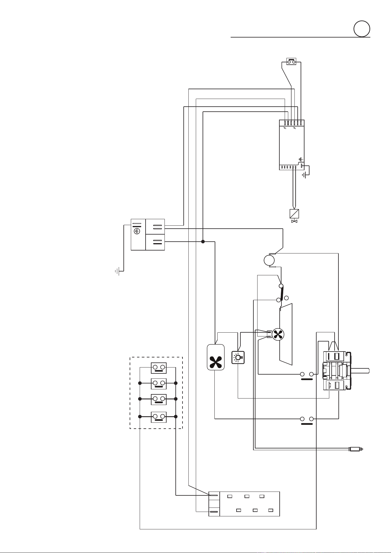
WIRING DIAGRAM
ELECTRIC DIAGRAM KEY
F1 SWITCH
MS SECURITYMICROSWITCH
S1 COOLINGFANFAILURELAMP
LF OVENLAMP
AS AIRFLOWSWITCH
V FANMOTOR
TL THERMALOVERLOAD
PA IGNITIONSWITCHESGROUP(COOKTOPBURNERS)
A IGNITIONCOIL
OS OVEN/BROILIGNITIONSWITCH
MU MAGNETUNIT-OVEN/BROILTHERMOCOUPLES
TO OVEN/BROILIGNITIONSYSTEM
CF COOLINGFANMOTOR
M TERMINALBLOCK
T EARTHCONNECTION
Sw
TC1
TC2
1
2
P1
P2
TC3
TC4
TC5
TC6
Sw
L
L
N
N
F1
S1
MSMS
AS
CF
LF
A
PA
M
L N
T
V
TL
MU
T0
T
OS
T-Zero

Themanufacturercannotbeheldresponsibleforpossibleinaccuraciesduetoprin-
tingortranscriptionerrorsinthepresentbooklet.
Themanufacturerreservestherighttomakeallmodicationstoitsproductsdee-
mednecessaryformanufactureorcommercialreasonsatanymomentandwithout
priornotice,withoutjeopardisingtheessentialfunctionalandsafetycharacteristics
oftheappliances.
Cod.1104009-ß3