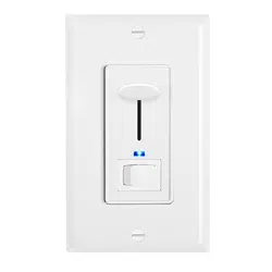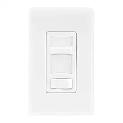
MEW-DM660 INSTALLATION INSTRUCTIONS
Caution: Read all notes prior to installation
WARNING: TO AVOID FIRE, SHOCK, OR DEATH; TURN
OFF POWER at the circuit breaker or fuse and test that the
power is off before wiring!
Warranty: Maxxima extends a 1 year limited warranty to the original purchaser that the products purchased are free from defects in material and/or workmanship only. The limited warranty is not transferable. This
offer does not constitute in any way a product guarantee and Maxxima does not hereby assume any obligation whatsoever beyond sending a replacement product at no charge durring the warranty period.
Maxxima, 125 Cabot Ct., Hauppauge, NY 11788
TEL: 631.434.1200 FAX: 631.434.1457
www.maxximastyle.com
IMPORTANT: For 3-way applications, note that one of the screw terminals
from the old switch being removed will usually be a different color (Black)
or labeled Common.Tag that wire with electrical tape and identify it as the
common (Line or Load) in both the dimmer wall box and the standard
3-way switch wall box. The remaining two wires on the brass or lighter
screw terminals of the old switch are the travelers.
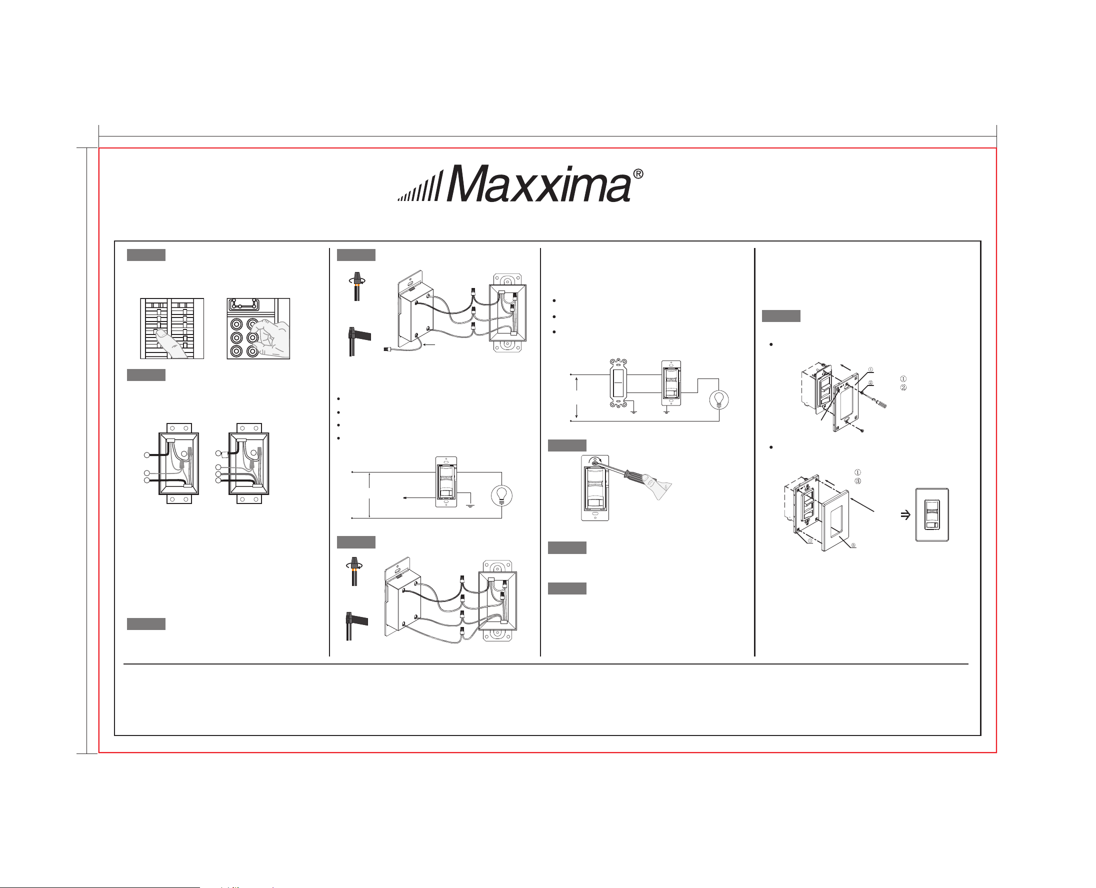
Single-Pole
1. Line (Hot)
2. Neutral
3. Ground
4. Load
3-Way
1. Line or Load Common
(See importaint instructions below)
2. Neutral
3. Ground
4. First Traveler
5. Second Traveler
Connect wires as follows:
Screw wire nuts on clockwise making sure no bare conductors show
below the wire connectors. Secure each connector with electrical tape.
Connect wires as follows:
Screw wire nuts on clockwise making sure no bare conductors show
below the wire connectors. Secure each connector with electrical tape.
NOTE: In a 3-way circuit, only one dimmer can be used.
Restore Power:
Restore power at the circuit breaker or
fuse. Installation is complete.
• Pull off the pre-cut insulation from the Dimmer leads.
• Make sure that the ends of the wires from the wall
box are straight (cut if necessary).
NOTE: If the wiring in the wall box does not resemble
any of these configurations, consult an electrician.
Indentifying your wiring application
(most common):
Single-Pole wiring application:
Preparing wires:
3-way wiring application:
Dimmer Mounting:
STEP 1
STEP 2
Installation may now be completed by carefully
positioning all the wires to provide room in the
wall box for the dimmer. Mount the dimmer into
the box with supplied mounting screws.
ONOFF
ONOFF
ONOFF
ONOFF
ONOFF
ONOFF
ONOFFONOFF
ONOFF
ONOFF
ONOFF
ONOFF
2
4
1
5
3
2
3
1
4
Dimmer
Dimmer3-Way Switch
Insulating
Label
This wire is used in 3-way
installations onl
y.
For single pole installations,
twist with wire nut
Ground
Neutral
Red
Red and White
Yellow and
Green
Black
Ground
Neutral
Red
Black
Yellow and
Green
Red and White
Installing wall plate:
Place the mounting frame
①
over your installed dimmer
and secure it using provided screws
②.
Cover the face plate
③
over the installed mounting
frame
①
and gently push it to ensure flush fit.
Mounting Frame
Provided screws
Mounting Frame
Face Plate
STEP 2
STEP 3
STEP 4A
STEP 4B
STEP 5
STEP 8
STEP 6
Connect the yellow and green dimmer wire to the green or bare copper
ground wire in the wall-box, and twist them with wire nut.
Connect the black dimmer wire to the hot input wire removed from the
switch, and twist them with wire nut.
Connect the red dimmer wire to the load wire removed from the switch,
and twist them with wire nut.
Use remaining wire nut to cap the remaining red and white wire on dimmer.
Connect the yellow and green dimmer wire to the green or bare copper
ground wire in the wall-box, and twist them with wire nut.
Connect the black dimmer wire to the hot input wire with tag removed
from the switch, and twist them with wire nut.
Connect the red dimmer wire, red and white dimmer wire to the remaining
3-way switch’s two wires removed from the switch, and twist them with
wire nuts.
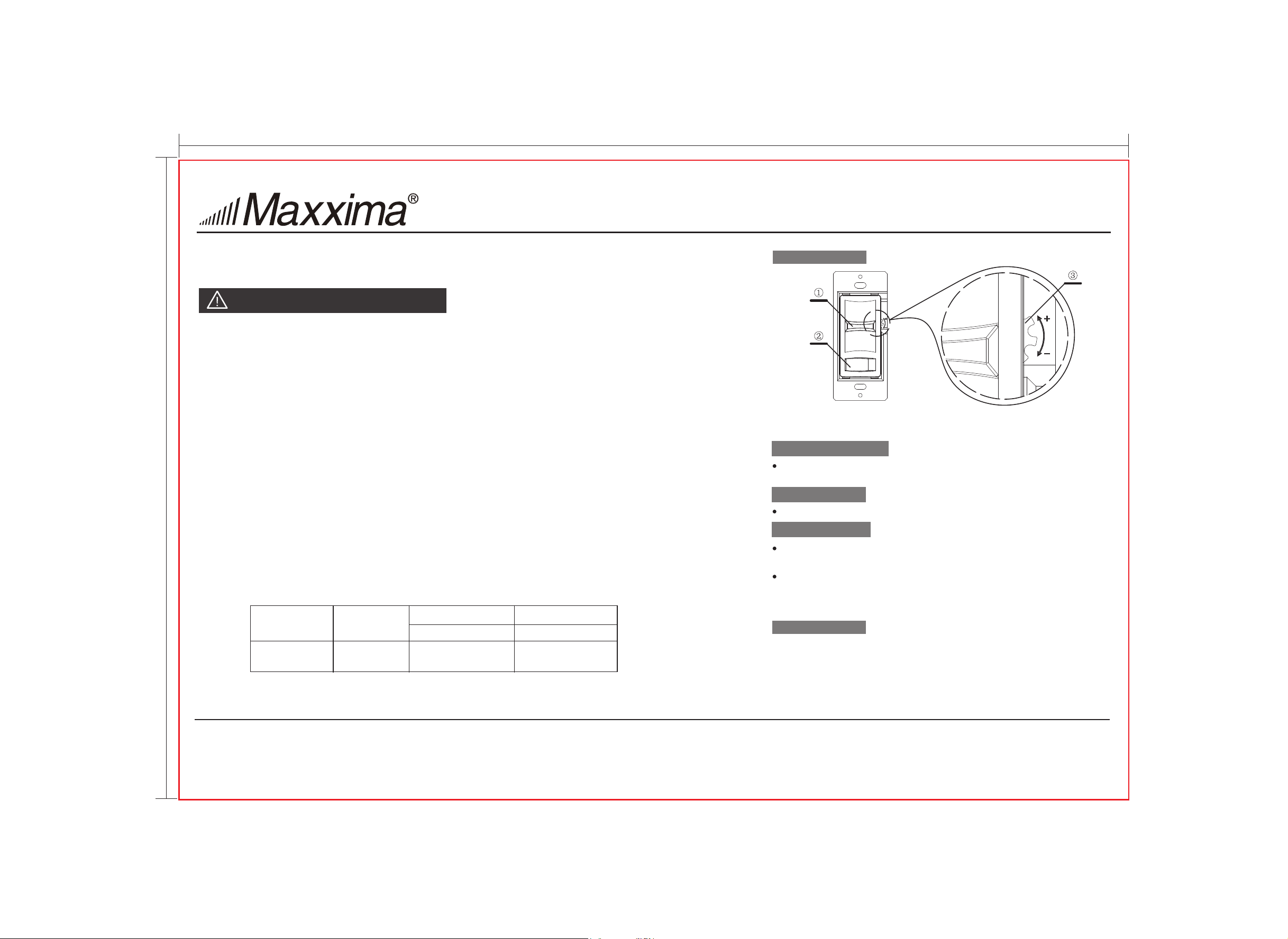
Dimmer Range Adjustment:
STEP 7
After installation (see other side), adjust circuit dimming as follows:
1. Turn on the switch and move the slide dimmer to the lowest setting.
2. Adjust the Adjustment Dial all the way up (Counter-Clockwise).
NOTE: If the dial stops in either direction, do not continue to turn it.
3. Begin to adjust the Adjustment Dial down (Clockwise) until the preferred
lowest light level is acheived and the light output is stable for all lamps
on the circuit. If all the lamps on the circuit go out, adjust the setting
back up slightly (Counter-Clockwise).
4. Once the lowest light level is set, test the slide dimmer in the lowest
position by switching the dimmer off and then on with the ON/OFF switch to
verify all the lamps turn on at the lowest level.
5. If all the lamps do not turn back on, repeat steps 1-4, but set the lowest light
level slightly higher than the previous attempt.
6. Once all the lamps are dimming properly, install the faceplate.
Black
Green/
Bare
Red
Black
Green/
Bare
Red
Red
Line 120VAC, 60Hz
Line 120VAC, 60Hz
Yellow and
Green Ground
Yellow and
Green Ground
Green Ground
Red
Red
Red
Red/White
Black (Hot)
Black (Hot)
Black
Load
Load
White (Neutral)
White (Neutral)
Top
Top
NOTE: When installing the faceplate, ensure that it is in the correct orientation.
Insert wires
straight then
twist clockwise
Electrical
Tape
Insert wires
straight then
twist clockwise
Electrical
Tape
285*192mm
192
285
NOTE: If using the dimmer in a 3-way application, the lights will turn
ON at brightness set on the dimmer’s slide control lever. The switch
location only controls the on or off functions.
INSTALLATION INSTRUCTIONS for MEW-DM660 Dimmer Switch
Important Notes
Please read before installing (COMPLETE INSTALLATION INSTRUCTIONS CONTINUED ON THE OTHER SIDE)
1. Use only permanently installed 120V AC fixtures using incandescent, halogen, dimmable LED
or dimmable CFL lamps. To avoid overheating and possible damage to other equipment, do not use to control
receptacles, flourescent lighting fixtures or transformer-supplied appliances.
2. Always use appropriate electrical power verification instruments to verify that the power is OFF before
installing the dimmer
3. Install in accordance with all national and local electric codes.
4. Only use one dimmer in a 3-way circuit.
5. When no “grounding means” exists within the wall box then NEC 2008, Article 404-9 allows a dimmer without a
grounding connection to be installed as a replacement, as long as a plastic, non-combustable wallplate is used.
For this type of installation, cap the green ground wire on the dimmer.
6. For new installations, install a test switch before installing the dimmer.
7. Protect the dimmer from dust and dirt when painting or spackling.
8. It is normal for the dimmer to feel warm to the touch durring operation.
9. Clean the dimmer with a soft, damp cloth only. Do not use any chemical cleaners.
10. For indoor use only.
11. Mount the dimmer to the wall box using the provided screws. The dimmer must be mounted vertically. See the
stamp on the dimmer for correct positioning.
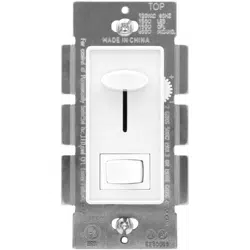
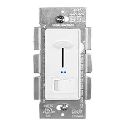
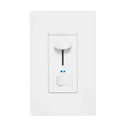
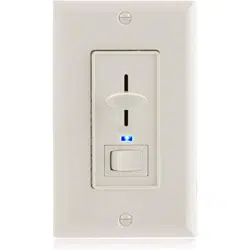
① Slide Control Lever ② Rocker Switch ③ Adjustment Dial
WARNINGS AND CAUTIONS
OPERATION
Slide Control Lever ①
Rocker Switch ②
Move slide control lever ① up to increase brightness, move down
to decrease brightness.
Press the rocker switch ② of the dimmer, turn power on or off.
Adjustment Dial ③
Turn clockwise the adjustment dial ③ to decrease brightness,
turn counter-clockwise to increase brightness.
Adjustment dial ③ can adjust and set the minimum brightness
level of the bulbs and maximize the dimming range.
Detail see step 7.
Maxxima, 125 Cabot Ct., Hauppauge, NY 11788
TEL: 631.434.1200 FAX: 631.434.1457
www.maxximastyle.com
Model No. Rated Voltage
MEW-DM660 120V:60Hz 200W/600W 3W/15W
Max.Load
LED/Incandescent
Min.Load
LED/Incandescent
FUNCTIONS
285*192mm
192
285