DE FILTER 60 FT / 48 FT
SKU: 75205
SKU: 75206
INSTALLATION AND USER’S GUIDE
Read all safety warnings and instructions.
Failure to follow the warnings and
instructions may result in electric shock,
fire and/or serious injury. Save all warnings
and instructions for future reference.
DANGER
75205
75206

THIS PAGE INTENTIONALLY LEFT BLANK

CUSTOMER SERVICE
If you have any questions about ordering our pool pumps and replacement parts or pool products, please feel
free to contact us using the following contact information:
Customer Service and Technical Support
Phone: (909) 628-0880
Email: [email protected]
Hours of Operation: Monday – Friday, 9AM – 4PM (CST)
TABLE OF CONTENTS
CUSTOMER SERVICE
Customer Service and Technical Support
IMPORTANT SAFETY INSTRUCTIONS
Legends and Symbols
GENERAL SAFETY
OVERVIEW (PRODUCT INFORMATION)
PACKAGE CONTENTS
FILTERING
OPERATION
WINTERIZING
REPLACEMENT PARTS
DISCLAIMER
Parts Diagram
DISASSEMBLY INSTRUCTIONS
CLEANING
1
1
1
2
2
3-4
5
5
6
6
6
7
7
8
9
9
9
10
11-23
24
24
25
25
26
26
27
REMOVING THE MANUAL AIR RELIEF VALVE
SERVICE AND REPAIRS
TROUBLESHOOTING
TABLE OF CONTENTS
INSTALLATION
GENERAL INFORMATION
INSTALLATION
STARTING THE PUMP AND FILTER SYSTEM
MAINTENANCE
FILTER MAINTENANCE
ASSEMBLY INSTRUCTIONS (STEP 1 - 21)
1
ATTENTION INSTALLER: This manual contains vital information regarding the installation, operation, and safe
use of this variable speed pump. It is essential to provide this manual to the end user of the product. Failure to
read and follow all instructions could lead to severe injuries.
USE OF NON-XTREMEPOWERUS REPLACEMENT PARTS VOIDS WARRANTY
DANGER: Ignoring these hazards can result in death, severe personal injury, or significant
property damage.
WARNING: Indicates potential hazards that can result in severe personal injury, death, or
significant property damage. Ignoring these warnings presents a real danger.
CAUTION: Indicates potential hazards that can result in minor or moderate personal injury,
property damage, or actions that are unpredictable and unsafe. Ignoring these cautions
presents a potential hazard.
NOTICE: This label indicates important special instructions that are not directly related to
hazards.
This guide provides instructions for installing and using the pump. If you have any questions about the
equipment, please contact XtremepowerUS.
This guide contains important information about safely installing and operating this product. After installation,
make sure to share this information with the owner/operator or leave it with them for their reference.
Legends and Symbols
When you come across the safety-alert symbol on your equipment or in this manual, pay attention to the
following signal words and remain vigilant about the potential for personal injury.
IMPORTANT SAFETY INSTRUCTIONS
WARNING
CAUTION
NOTE
READ, UNDERSTAND, AND FOLLOW ALL SAFETY AND OPERATION INSTRUCTIONS.
FAILURE TO COMPLY WITH THESE INSTRUCTIONS MAY RESULT IN SEVERE PERSONAL INJURY OR
DEATH.
CAUTION
To minimize the risk of injury, do not allow children to use or climb on this product. Always
supervise children closely. According to the ANSI/NSPI-4 Standard (for above-ground and on-ground pools),
components like the filtration system, pumps, and heaters should be positioned to prevent young children from
accessing the pool.
CAUTION
COMPONENT SEPARATION HAZARD
Pool and spa water circulation systems operate under dangerous pressure during startup, regular operation, and
potentially after pump shutdown. Failure to follow safety and operation instructions can cause explosive
component separation in the upper filter body, resulting in severe personal injury or death. This product should
be installed and serviced exclusively by a qualified pool professional.
WARNING
2
IMPORTANT SAFETY INSTRUCTIONS
DANGER
TO AVOID COMPONENT SEPARATION:
• Adhere to all safety and operation instructions.
• Do not operate the water circulation system if any system component is improperly assembled, damaged,
missing, or not a genuine component.
• Before performing maintenance on the water circulation system, ensure that all system and pump controls
are in the OFF position and the filter manual air relief valve is in the OPEN position.
• Use ONLY genuine components to avoid potential failures and explosive separation.
• Never rely on hand-tightening the clamp nut to the clamp bolt. Use a ¾" socket on a torque wrench and
torque the clamp nut and clamp bolt to 150 inch-lbs.
• Before starting the system pump, ensure that the filter manual air relief valve body is in the LOCK position in
the filter upper body.
• Check that all system valves are positioned to allow water from the filter to return to the pool before starting
the system pump.
• Prior to starting the system pump, make sure the manual air relief valve is in the OPEN position.
• Do not stand over or near the filter when starting the pump.
• If water leakage occurs around the filter tank clamp area, immediately shut off all system circulation pumps
and electrical power. Do not approach the filter until all water flow has ceased. Follow the instructions in this
owner’s manual to reassemble the clamp system and stop the leak.
• Only close the manual air relief valve when a continuous stream of water (not air or a mixture of air and
water) is discharged from it.
• Do not change the filter control valve position while the system pump is running.
EXCESS PRESSURE HAZARD
Pressure testing the pump and filter system above 50 PSI can lead to explosive component separation, resulting
in severe personal injury or death.
WARNING
ELECTROCUTION HAZARD
High Voltage electricity is present within the pool and spa equipment, posing a risk of electric shock and
electrocution, which can lead to severe personal injury or death.
WARNING
• Ensure that all electrical wiring complies with local codes, regulations, and the National Electrical Code
(NEC).
• Prior to any service or maintenance on electrical equipment, turn off all electrical power.
• Consult a licensed electrician or building inspector to learn about local electrical codes and bonding
requirements.
• Confirm that water discharged from the filter manual air relief valve is directed away from electrical devices
and avoid locating pump controls over or near the filter.
COMPONENT SEPARATION HAZARD
EXCESS PRESSURE HAZARD
ELECTROCUTION HAZARD
3
IMPORTANT SAFETY INSTRUCTIONS
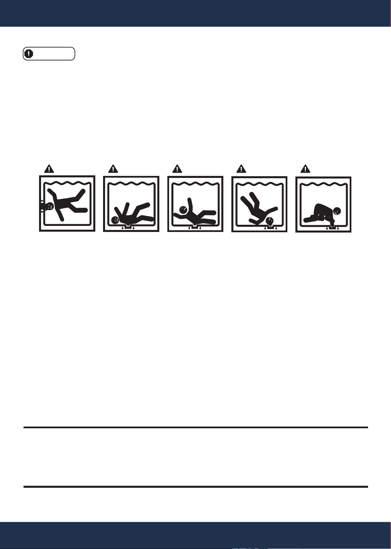
SUCTION ENTRAPMENT HAZARD
Suction outlets and/or suction outlet covers that are damaged, broken, cracked, missing, or unsecured can pose
severe injury and death risks due to various entrapment hazards:
WARNING
• Hair Entrapment: Hair can become entangled in suction outlet covers.
• Limb Entrapment: Inserting a limb into a damaged, broken, cracked, missing, or unsecured suction outlet
sump or cover can lead to mechanical binding or limb swelling.
• Body Suction Entrapment: Negative pressure applied to a large portion of the body or limbs can result in
entrapment.
• Evisceration/Disembowelment Entrapment: Directly applying negative pressure to the intestines through an
unprotected suction outlet sump or cover can cause evisceration/disembowelment entrapment.
• Mechanical Entrapment: There is a risk of jewelry, swimsuits, hair decorations, fingers, toes, or knuckles
getting caught in openings of a suction outlet cover, leading to mechanical entrapment.
TO MINIMIZE ENTRAPMENT HAZARDS:
• Install a minimum of two functioning suction outlets per pump. Suction outlets in the same plane (e.g., floor
or wall) must be positioned at least three feet (3') or one meter apart, measured from the nearest points.
• Place dual suction outlets to prevent "dual blockage" by a user.
• Avoid locating dual suction outlets on seating areas or their backrests.
• Design the pool or spa circulation system in accordance with ANSI/APSP-7 2006.
• Ensure that suction outlet covers adhere to ANSI/ASME A112.19.8 standards.
• Do not use the pool or spa if any suction outlet component (cover/grate) is damaged, broken, cracked,
missing, or not securely attached.
• Promptly replace any damaged, broken, cracked, missing, or insecurely attached suction outlet components.
• Regularly clear suction outlet components of debris such as leaves, dirt, hair, paper, and other materials to
reduce the potential for suction entrapment.
SAVE THESE INSTRUCTIONS
Suction outlet covers and grates have a limited lifespan and should be
inspected regularly and replaced within the specified time frame.
SUCTION ENTRAPMENT HAZARD
DANGER DANGER DANGER DANGER DANGER
4
IMPORTANT SAFETY INSTRUCTIONS
4
5
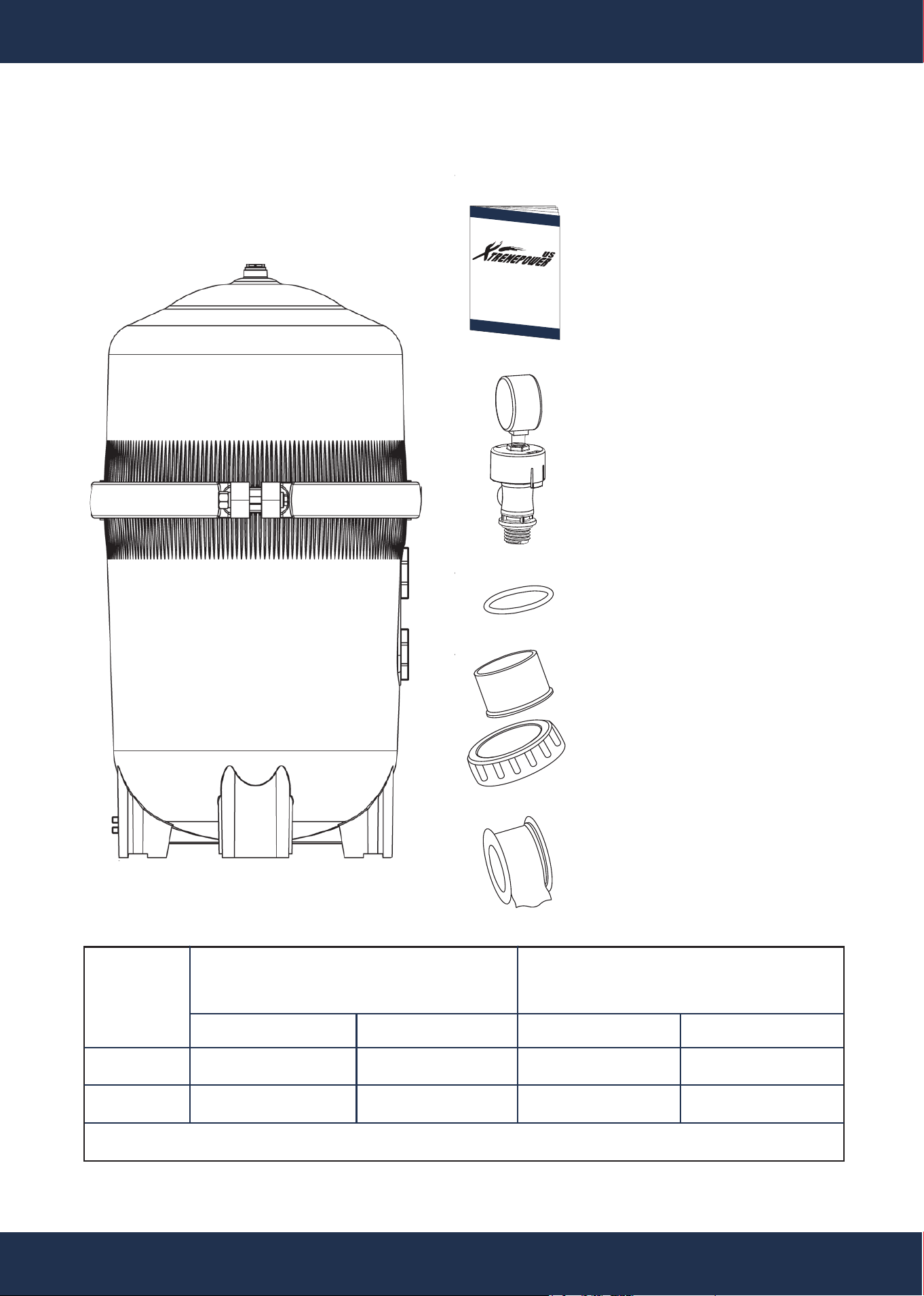
OVERVIEW (PRODUCT INFORMATION)
PACKAGE CONTENTS
PARTS # 1
PRESSURE GAUGE
1 PC(S)
PARTS # 2
MANUAL AIR RELIEF ASSEMBLY
1 PC(S)
PARTS # 15
ADAPTOR PLUG SCREW
2 PC(S)
PARTS # 16
O-RING
2 PC(S)
D.E. POOL FILTER 1 PC(S)
75205
75206
MAXIMUM WORKING PRESSURE FOR ALL MODELS 50 PSI (3.45 BAR)
EFFECTIVE FILTRATION RATE
DESIGN FLOW RATE
Residential Commercial
MODEL
FT
2
60
48
M
2
5.7
4.46
GPM
120
96
LPM
454
363
THREAD SEALING TAPE
1 PC(S)
INSTRUCTION MANUAL
1 PC(S)
SKU 75205 / SKU 75206
GENERAL INFORMATION
The Vertical Grid D.E. Filter provides an effective water filtration solution, combining user-friendly operation with
corrosion-resistant construction. It employs diatomaceous earth (D.E.), renowned as the most efficient dirt
remover and filter medium available. During the initial start-up, D.E. is typically introduced through the skimmer,
coating the filter elements, which are protected by a custom monofilament polypropylene filter cloth. As pool
water is pumped through the control valve into the lower section of the filter tank, the D.E. coating efficiently
captures even the smallest particles, resulting in crystal-clear, sparkling water.
Over time, as dirt accumulates in the filter, it creates resistance to water flow, leading to increased pressure and
reduced flow. This indicates that the D.E.’s dirt-holding capacity has been reached, signaling the need to clean
(backwash) the filter. With the control valve set to the backwash position, water reverses through the filter,
flushing out trapped dirt, debris, and D.E. through the waste line. Once the filter has been backwashed and
cleared, the control valve is manually returned to the filter position, and a fresh supply of D.E. is added to resume
filtration.
This product must be installed and serviced exclusively by a
qualified pool professional. Below are important installation
guidelines to follow:
1. The filter system should be situated on a level concrete slab
or another sturdy base. Choose a well-drained and
ventilated area that does not flood during rainfall. Position
the filter so that the piping connections and winter drain are
easily accessible for operation, service, maintenance, and
winterization.
2. Place the filter in a position that allows it to drain by gravity.
3. If possible, position the pump and filter in a shaded area to
protect them from continuous direct sunlight and excessive
heat.
4. Attach the appropriate Filter Control Valve (not included) to
the filter. First, lubricate the O-ring. Align the two valve pipe
connections, each with an O-ring in place, with the two
openings on the side of the filter tank, and press them in
firmly. Secure the assembly to the tank connections with
the two bulkhead lock nuts. Be careful not to over-tighten.
5. Connect the pool suction plumbing, linking the skimmer,
pool outlet, and the pump.
6. Connect the pump discharge (pump OUTLET) to the filter
INLET.
7. Connect the filter OUTLET to the pool return plumbing
lines.
8. Avoid placing pump controls directly over or near the filter.
9. Ensure that the water discharge from the Manual Air Relief
Valve (MAR) is directed away from electrical devices to
prevent any potential hazards.
INSTALLATION
SKU
INFO
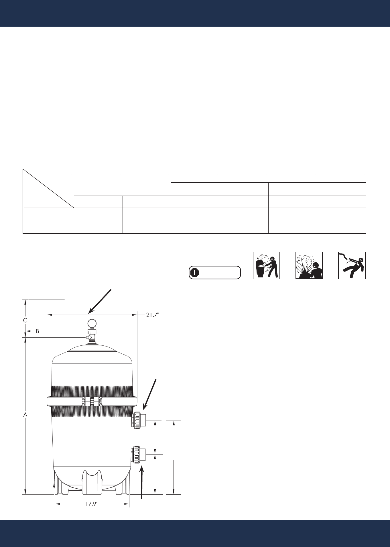
IN CM IN CM IN CM
75205 37 94 18 46 18 46
75206 44.3 112.5 18 46 22 56
REQUIRED CLEARANCE
"B" SIDE "C"ABOVE
A
INSTALLATION LOCATION
Manual Air Relief
8”
7.5”
15.5”
Outlet
Inlet
6
WARNING
STARTING THE PUMP AND FILTER SYSTEM
BEFORE STARTING THE PUMP
• Use ONLY Original Components: Utilize only original components, as non-original parts may malfunction
during use, potentially leading to explosive separation of components.
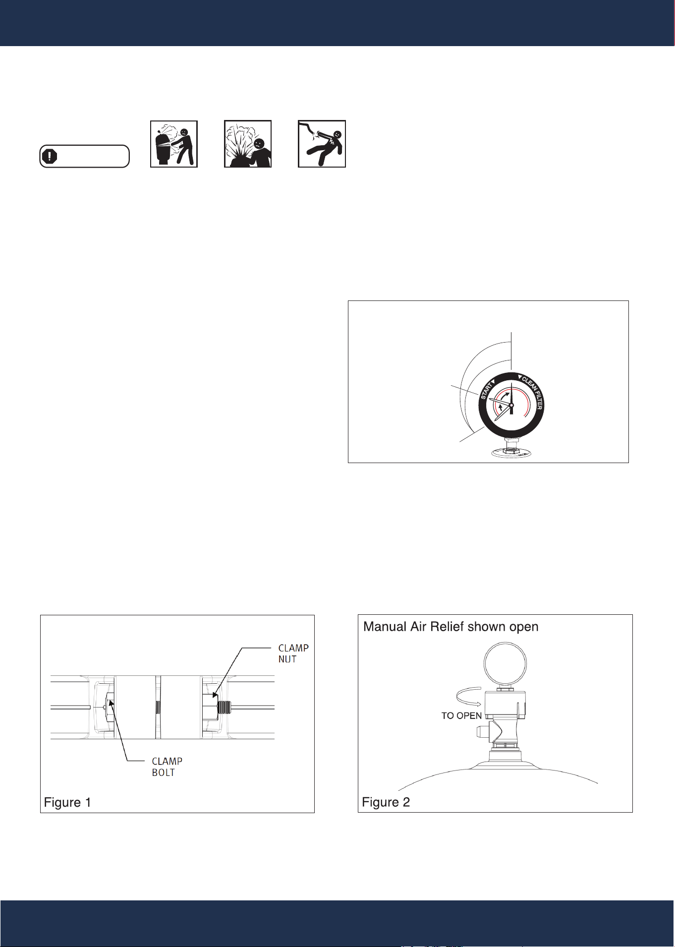
• Verify that the upper and lower filter bodies are securely fastened with the filter body clamp.
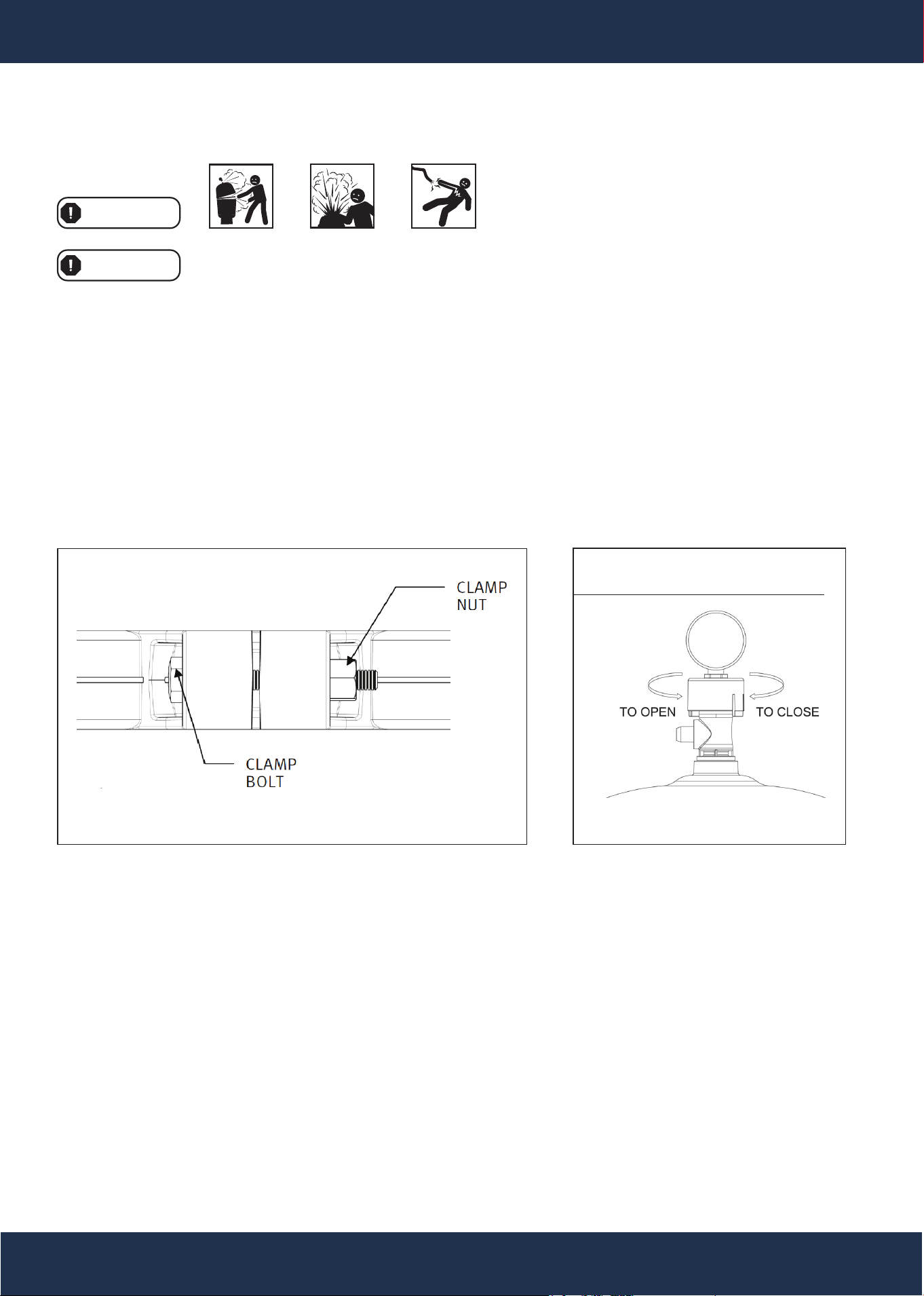
• Avoid relying solely on hand-tightening the clamp nut. Instead, use a ¾" socket with a torque wrench to
tighten the clamp nut to the clamp bolt, applying 150 inch-lbs of torque (refer to Fig. 1).
• Ensure the filter manual air relief valve is securely locked in position, and confirm that no filter components
are missing, damaged, or non-genuine (see Fig. 2).
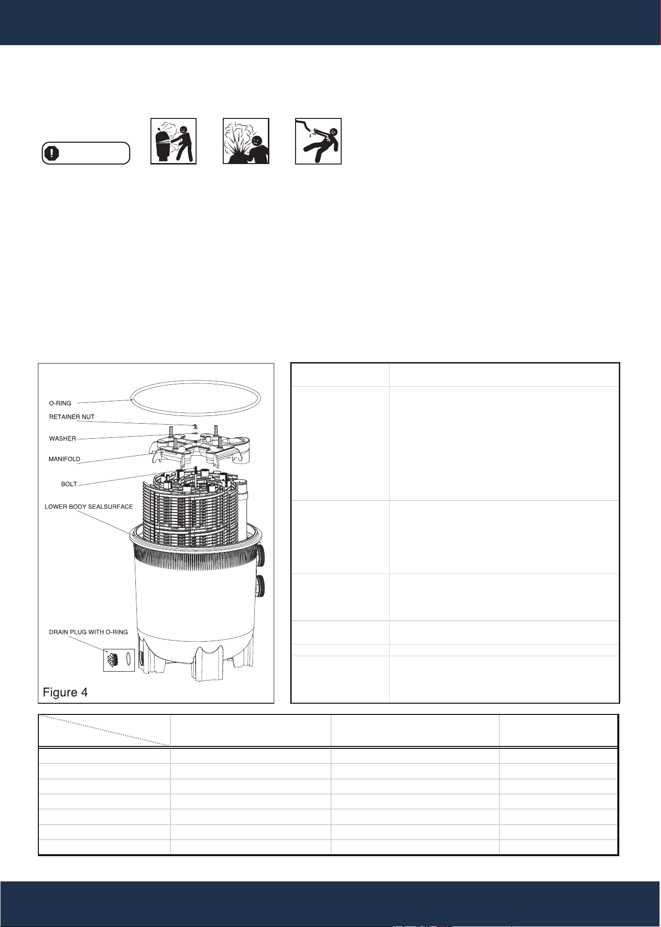
• Close Filter Drain: Note that the filter drain plug
requires an o-ring seal for proper closure (see Fig.
4).
• Open All System Valves: Ensure all system valves
are fully open to allow water to flow from the pool to
the filtration system and from the filter back to the
pool.
• Position the Manual Air Relief Valve: Place the
manual air relief valve in the OPEN position (see
Fig. 2).
STARTING THE PUMP
• Exercise Caution: When starting the system pump, avoid standing directly over or near the filter. If water
leakage occurs at the filter tank clamp, immediately turn off all system circulation pumps and disconnect the
electrical power. Do not approach the filter until the water leakage has completely stopped. To resolve the
leak, follow the clamp system reassembly instructions detailed on page 7 of this owner's manual.
• Closing the Manual Air Relief Valve: Return to the filter only after a steady stream of water (with no air or
a mixture of air and water) is discharged from the manual air relief valve. Once the water flow is consistent,
you can safely CLOSE the manual air relief valve.
• Important Safety Reminder: Always exercise extreme caution when following these instructions to ensure
the safe operation of your pump and filter system.
OPERATION
7
Figure 3
WARNING
CLEAN PRESSURE
Place Green Arrow
Here
TIME TO CLEAN FILTER CARTRIDGES
When Pressure Reaches Red Arrow
7-10 psi (0.49 - 0.69 bar)
S
T
A
R
T
C
L
E
A
N
F
I
L
T
E
R
0 psi
Six-Way Filter Control Valve Four-Way Filter Control Valve Two-Way Slide Valve
Filter
X X X
Backwash X X X
Rinse X
Waste X X
Recirculate X
Closed X
Pool or SPA Boost X
FUNCTION
VALVE TYPE
FILTER
BACKWASH
RINSE
WASTE
RECIRCULATE
CLOSED
POOL OR SPA BOOST
• Set the valve to FILTER for normal filtration.
• This setting is also used for regular vacuuming.
• Shut off the pump.
• Set the Filter Control Valve to BACKWASH.
• Start the pump and backwash for approximately two
minutes, or until the water coming out of the waste
line appears clean.
• Shut off the pump.
• Set the Control Valve to RINSE.
• Start the pump and run it for 20 seconds.
• Shut off the pump.
• Set the Filter control valve back to FILTER.
• Follow the pre-coating process to add fresh D.E.
• Water flows through the filter similarly to the FILTER
position, but in this setting, the water goes to
WASTE.
• This position is optimal for pre-coating if a large
cloud (pre-coat puff) is observed returning to the pool
during the pre-coating process.
• Use this setting to bypass the filter for draining or
lowering the water level.
• It is also useful for vacuuming heavy debris directly
to WASTE.
• Water is re-circulated through the pool system,
bypassing the filter.
• Shuts off the flow from the pump to the filter.
• This function directs water to be re-circulated through
the pool system without going through the filter,
which can help boost water flow for either the pool or
spa as needed.
8
OPERATION
OPERATION
FILTERING
Filtration begins once the filter has been pre-coated. As the filter removes dirt from the pool water, the
accumulated debris will create resistance to the flow. Consequently, the gauge pressure will increase, and the
flow rate will decrease. When the pressure rises 8-10 psi (0.55-0.69 bar) above the pre-coat pressure, it
indicates the need to perform a backwash (cleaning) operation on the filter. After your filter is operational and a
pressure reading is visible, align the green arrow with the current reading (refer to Fig. 3). When the pressure
reaches or exceeds the red or second arrow, it is essential to clean the filter.
Please note that during the initial cleanup of the pool, especially with a new pool or highly contaminated water,
more frequent backwashing may be required due to the heavy initial dirt load. Exercise caution and vigilance to
maintain the effectiveness of your filtration system.
WARNING
This product must be installed and serviced exclusively by a qualified pool professional.
WARNING
9
MAINTENANCE
Figure 6
Figure 5
MAINTAINING YOUR FILTER
FILTER DISASSEMBLY INSTRUCTIONS
1. Turn off all system circulation pumps and all electrical power on the equipment pad.
2. Set all system valves to a position that prevents water from flowing to the filter.
3. Ensure the manual air relief valve is in the OPEN position (refer to Fig. 6).
4. Remove the filter drain plug (Fig. 4) and drain the water from the filter.
5. Using 3/4" wrenches or hex sockets, loosen and remove the clamp nut and bolt (Fig. 5).
6. While securely holding both ends of the filter clamp, carefully spread the clamp ends and lift the clamp over
the upper filter body. Take care not to drop the clamp, as it may become damaged. Avoid striking the clamp
with metal tools to prevent damage.
7. Lift off the upper filter body, taking care not to use the pressure gauge as a lifting point.
REMOVING THE ELEMENT CLUSTER
1. Remove the upper filter body, unscrew the retainer nut, and then remove the manifold on top of the filter
(Fig. 4).
2. Remove the filter element cluster assembly by using a slight rocking motion and lifting it up.
3. Clean the filter element cluster.
CLEANING THE FILTER ELEMENT CLUSTER
The filter element cluster can be cleaned by washing it inside and outside with a garden hose. After hosing down
the filter element cluster, gently brush the pleated surface to remove fine particles for optimal results. Avoid using
high-pressure washing, as it can damage the filter element cluster. Some debris may remain on the element
cluster even after hosing.
Manual Air Relief Shown Open
WARNING
10
MAINTENANCE
FILTER REASSEMBLY INSTRUCTIONS
Before proceeding with re-assembly, note the following safety guidelines. This product must
be installed and serviced exclusively by a qualified pool professional.
WARNING
• Do not use any petroleum-based
solvents to clean the filter components.
• Do not lubricate the seal.
NOTE
WARNING
Figure 9
Figure 8
Never hit or strike the clamp with a hammer or metal tools.
Follow the operating instructions for 'Starting the Pump and Filter System'
(Refer to page 5).
REINSTALLING THE FILTER ELEMENT
CLUSTER ASSEMBLY
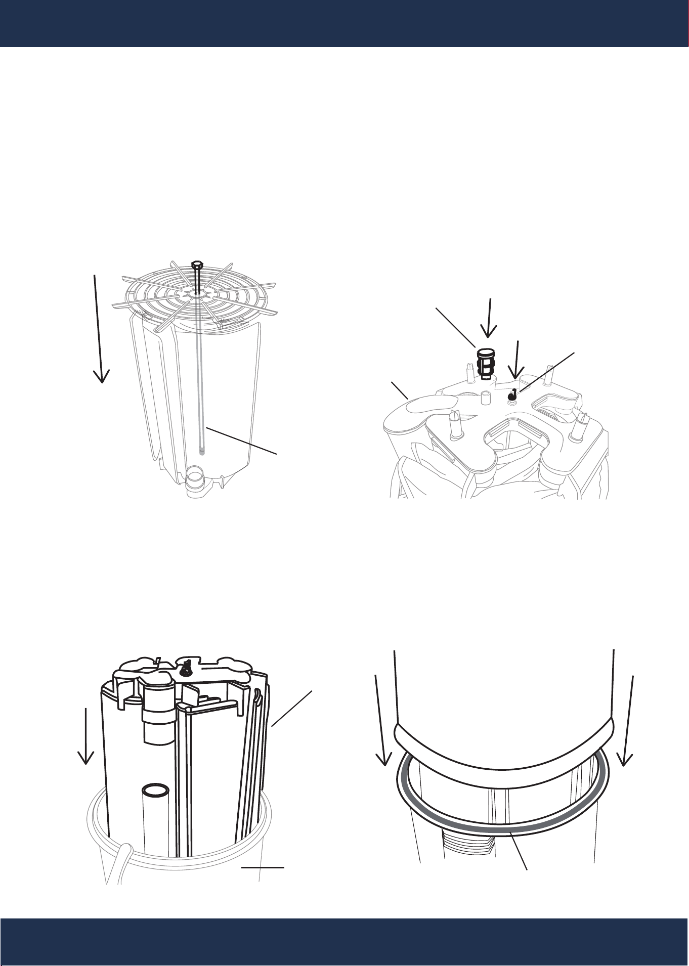
1. Lubricate the O-rings on the outlet elbow.
2. Carefully replace the filter element cluster into the filter tank,
ensuring that the top collector manifold outlet fits snugly over
the outlet elbow’s O-ring.
CLEANING THE SEAL RING AND SEAL SURFACE
1. Remove the filter tank seal.
2. Use a clean cloth to wipe the lower filter body seal surface,
thoroughly clean it of all dirt and debris (see Fig. 4). Do not
use any solvent.
3. Similarly, use a clean cloth to wipe the upper filter body seal
surface.
BODY AND CLAMP REASSEMBLY
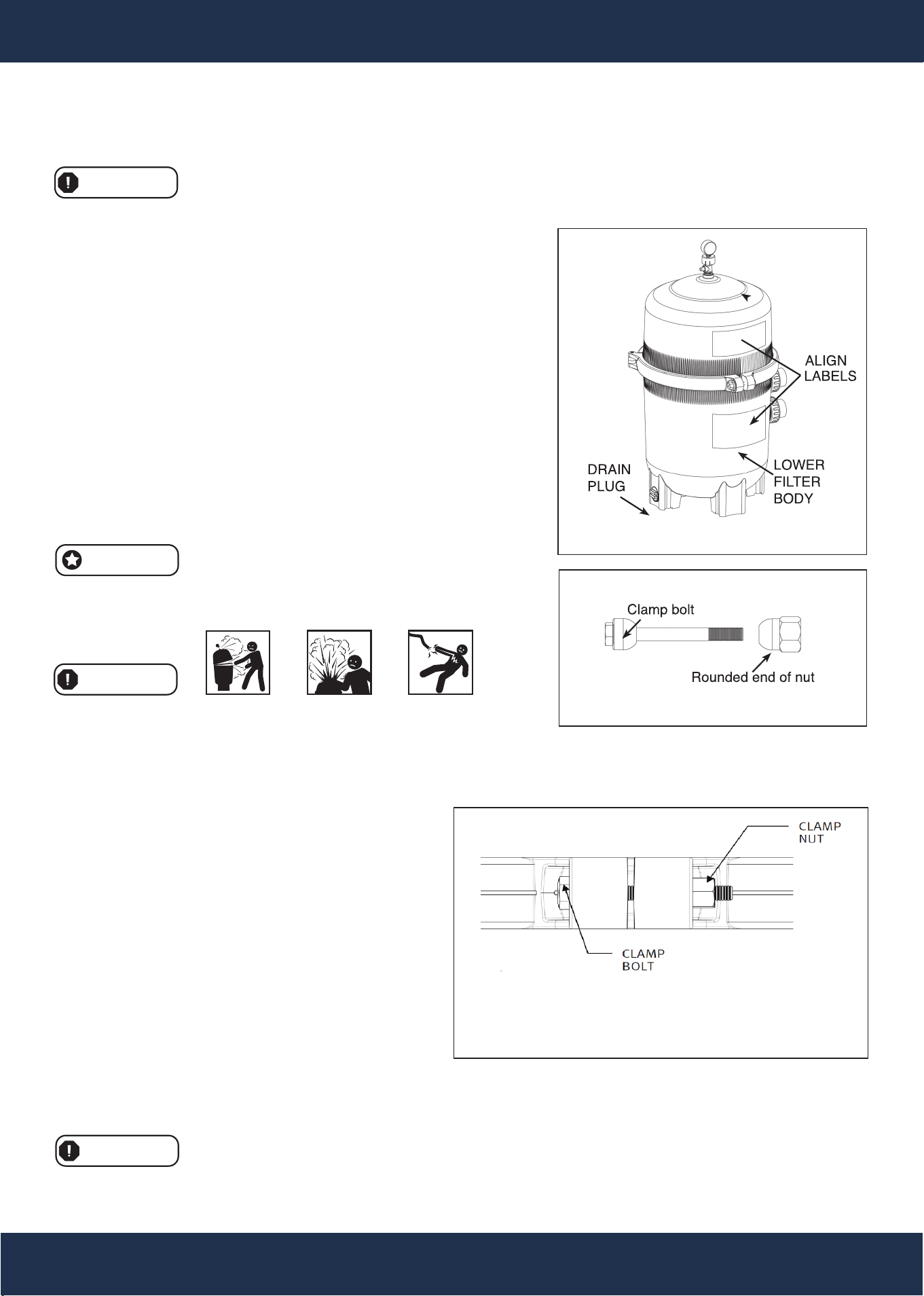
1. Place the metal-reinforced seal on the lower filter body (see Fig. 4). Position the upper filter body on top of
the metal-reinforced seal and the lower filter body, ensuring that all operation and safety labels are clearly
visible and that the upper filter body is centered
on the lower filter body. Press down firmly and
evenly on the upper filter body to seat the seal
(see Fig. 7).
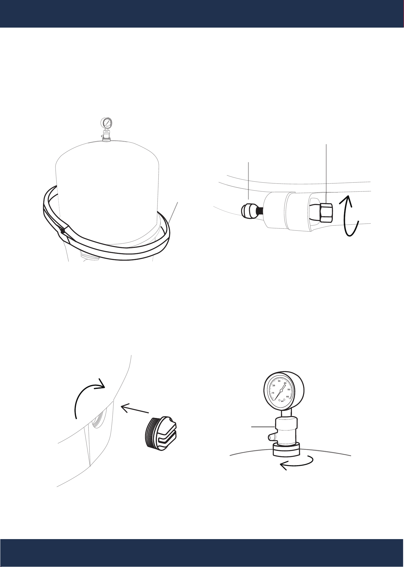
2. Reattach the filter clamp around both the upper
and lower filter bodies. Hold the clamp ends in
place to position the clamp, ensuring that the
clamp ends align with the safety and operation
labels on the filter bodies (see Fig. 7).
3. Insert the clamp bolt through the clamp ends and
thread the clamp nut onto the clamp bolt, with the
rounded end of the nut facing towards the ends of
the clamp (see Fig. 8).
4. Do not rely on hand-tightening the clamp nut to
the clamp bolt. Use a 3/4" socket on a torque wrench to tighten the clamp nut to the clamp bolt, applying 150
inch-lbs of torque (see Fig. 9).
WARNING
Tighten the clamp bolt and
nut using a torque wrench
to 150 inch-pounds.
Figure 7
11
ASSEMBLY
ASSEMBLY INSTRUCTIONS
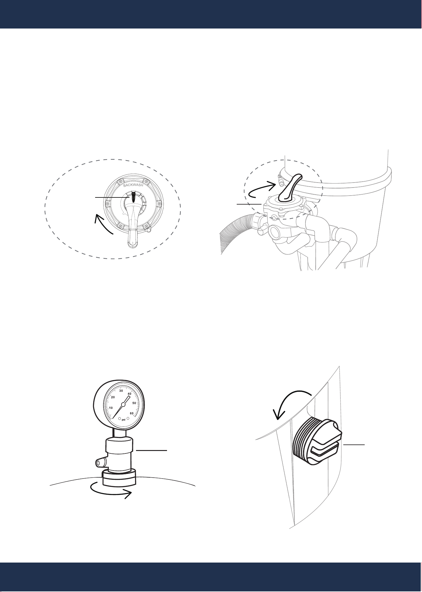
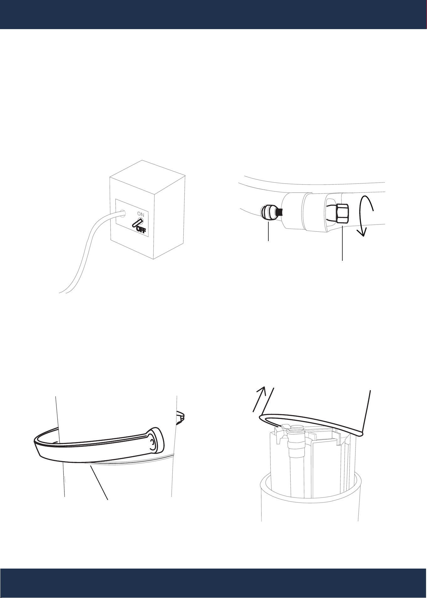
Step 1: Backwash Filter
Perform a backwash to remove old DE and
debris, facilitating a cleaner grid change.
BACKWASH
ROTATE
CLOCKWISE
ROTATE
CLOCKWISE
VALVE
Step 2: Open The Air Relief Valve
Flush out water from filter’s tank and plumbing
by opening the filter’s pressure gauge or valve.
ROTATE
COUNTERCLOCKWISE
Step 3: Drain Tank
Remove the filter’s drain cap for water
evacuation.
ROTATE
COUNTERCLOCKWISE
GAUGE
DRAIN
CAP
MAINTENANCE
12
Step 4: Power Shutdown
Ensure all equipment power is disconnected at
the breaker.
Step 5: Detach The Clamp Assembly
Remove the bolt and nut from the filter’s
clamp assembly, then remove the entire
clamp.
ROTATE
COUNTERCLOCKWISE
CLAMP ASSEMBLY BOLT
CLAMP ASSEMBLY NUT
Step 7: Lift The Tank Lid
Remove the upper filter body and set it
aside for reinstallation later.
Step 6: Continued From Step 5
CLAMP ASSEMBLY
UPPER FILTER BODY
MAINTENANCE
ASSEMBLY
ASSEMBLY INSTRUCTIONS
13
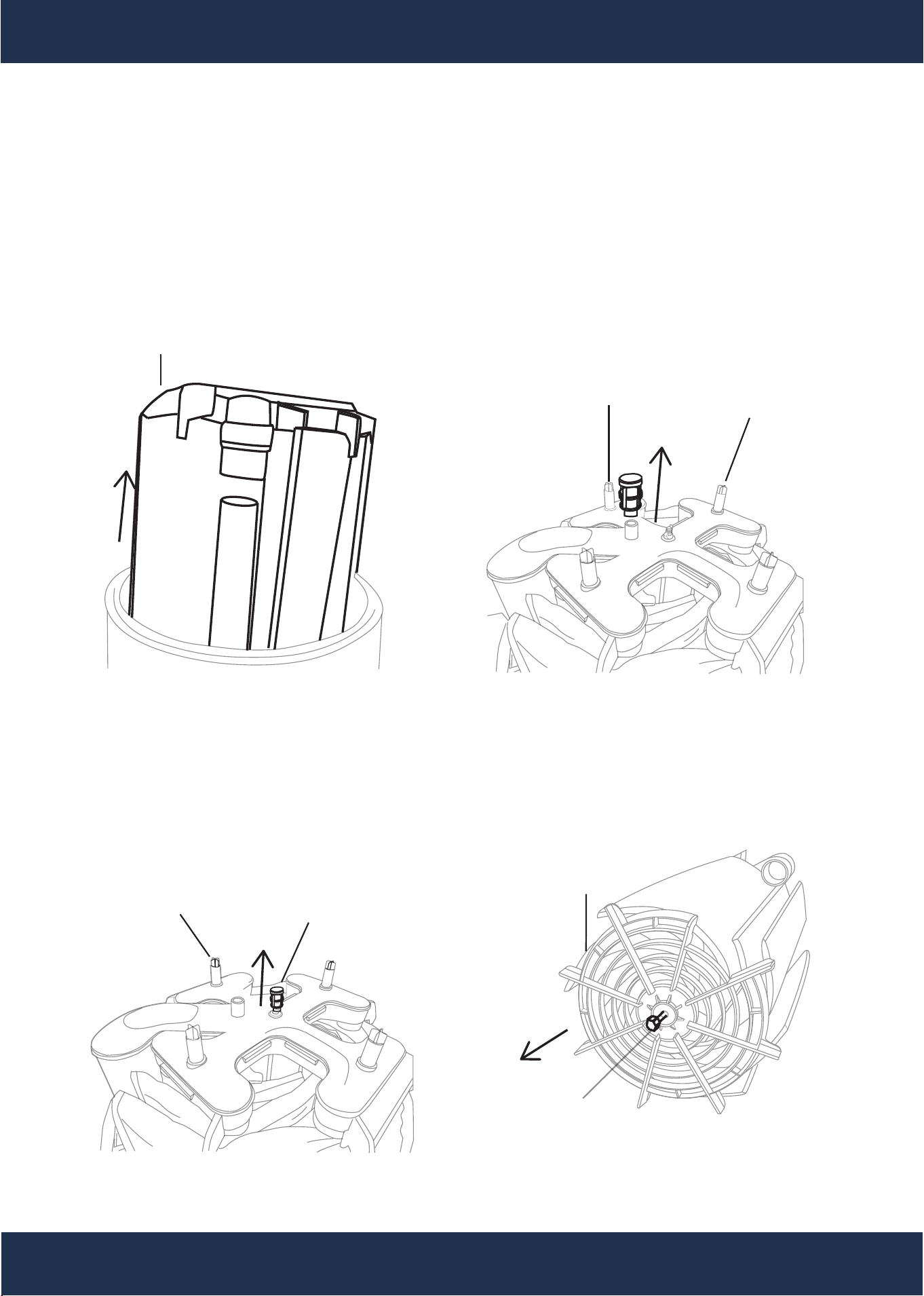
Step 8: Extract Grid Assembly
Lift the grid assembly from the filter’s tank. Detach the manifold cap from the top of manifold.
TOP GRID RETAINER SIDE
TOP MANIFOLD SIDE
MANIFOLD CAP
GRID ASSEMBLY
MANIFOLD
Step 9: Disassemble Grid Assembly
Detach the manifold from the tie rod by unscrewing the securing nut, preparing for individual
grid inspection or replacement.
TOP MANIFOLD SIDE
NUT
MANIFOLD
TIE ROD (SCREW)
BOTTOM GRID RETAINER SIDE
TOP MANIFOLD SIDE
GRID RETAINER
MAINTENANCE
ASSEMBLY
ASSEMBLY INSTRUCTIONS
LOWER FILTER BODY
14
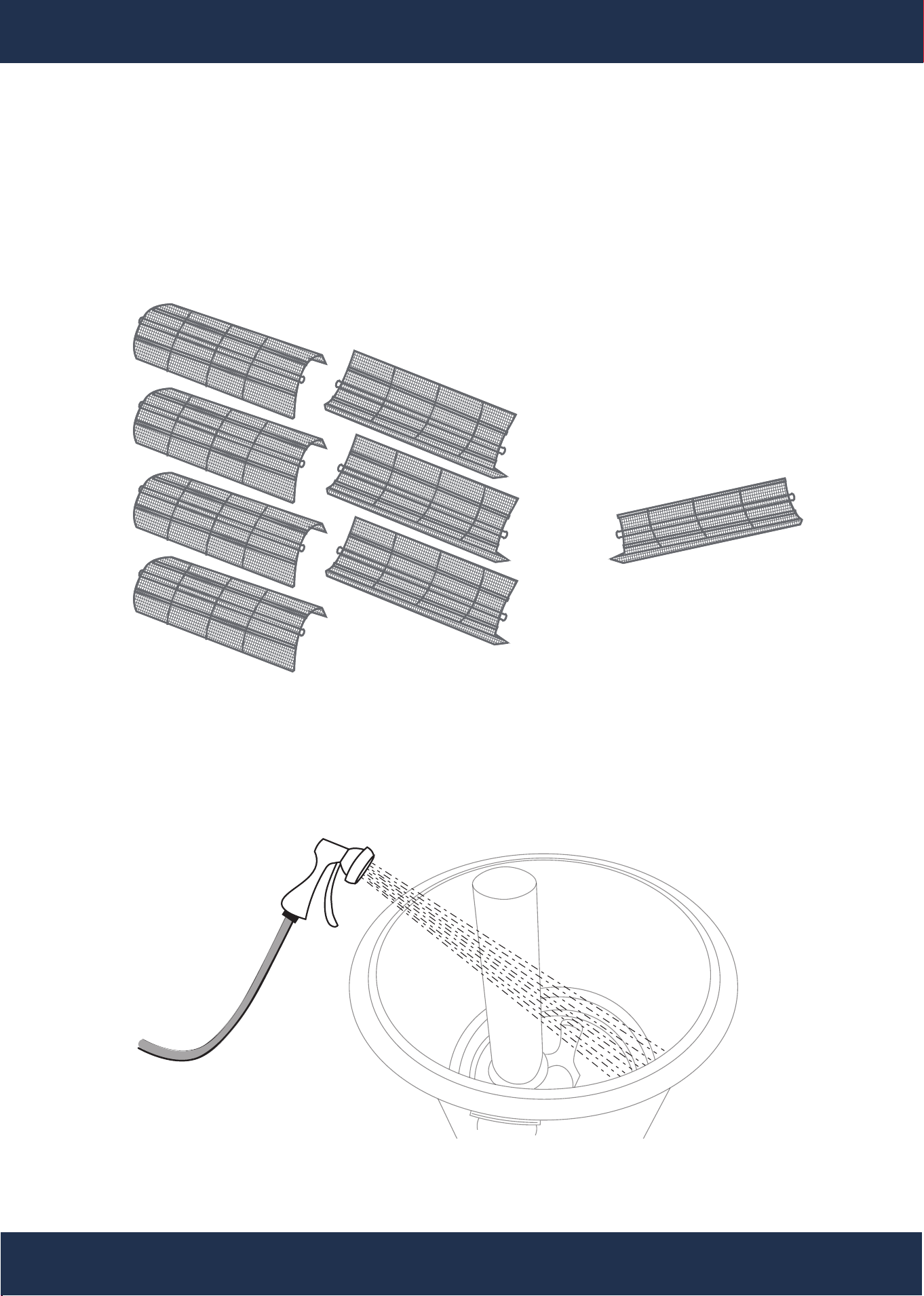
Step 10: Inspect and Select Grids
Evaluate grids for damage, removing only those necessary or replace the entire set as needed.
Step 11: Clean Tank
Wash out any residual DE powder or debris, ensuring the lower filter body and gasket grooves
are clean.
ONE SMALL GRID
ASSEMBLY
ASSEMBLY INSTRUCTIONS
MAINTENANCE
SEVEN LARGE GRID(S)
15
ASSEMBLY
ASSEMBLY INSTRUCTIONS
MAINTENANCE
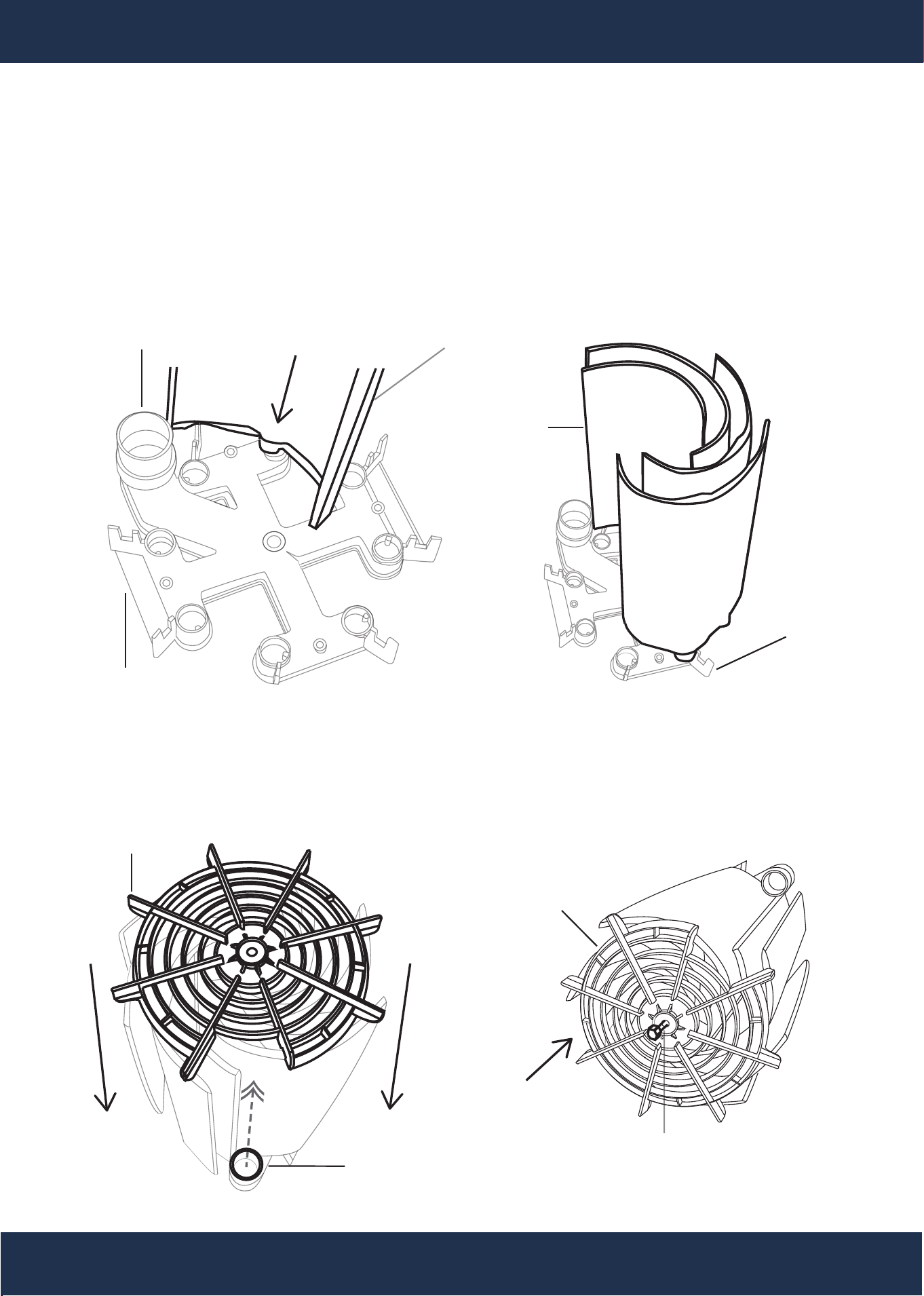
Step 12: Assemble New Grids
Place the manifold on a stable surface, then sequentially install grids into the manifold, starting
with the smaller grid at the standpipe port.
SMALL GRIDSTANDPIPE PORT
SMALL GRID
MANIFOLD
MANIFOLD
Step 13: Install Grid Retainer
Align the grid retainer and top standpipe mani-
fold port, ensuring correct grid placement.
Step 14: Insert Tie Rod
Insert the tie rod through the retainer and
manifold.
GRID RETAINER
STANDPIPE
MANIFOLD PORT
TIE ROD (SCREW)
BOTTOM GRID RETAINER SIDE
TOP MANIFOLD SIDE
GRID RETAINER
16
Step 17: Position New Grid Assembly
Align and install the grid assembly within the
lower filter body, ensuring proper standpipe
alignment, then reassemble the manifold cap
onto the top of manifold.
TOP MANIFOLD SIDE
Step 18: Place Tank Lid
Reattach the upper filter body, maintaining
the o-ring in its designated groove.
GRID
ASSEMBLY
LOWER FILTER
BODY
ASSEMBLY
ASSEMBLY INSTRUCTIONS
MAINTENANCE
Step 16: Fasten Tie Rod
Attach the tie rod nut to secure the mani-
fold at the assembly's top. Attach the
manifold cap to the top of manifold.
TOP MANIFOLD SIDE
THE TIE
ROD NUT
MANIFOLD
Step 15: Position The Grid Assembly Upright
Flip the grid assembly to an upright position,
ensuring both the retainer and manifold are held
securely.
TIE ROD
SCREW
BOTTOM GRID RETAINER SIDE
TOP MANIFOLD SIDE
MANIFOLD CAP
UPPER FILTER BODY
O-RING
17
Step 19: Attach The Clamp Assembly
Evenly position the clamp assembly, and securely fasten the bolt and nut.
CLAMP
ASSEMBLY
ROTATE
CLOCKWISE
CLAMP
ASSEMBLY BOLT
CLAMP
ASSEMBLY NUT
ASSEMBLY
ASSEMBLY INSTRUCTIONS
MAINTENANCE
Step 20: Attach The Drain Plug
Secure the filter’s drain plug.
ROTATE
CLOCKWISE
Step 21: Leak Testing
Fasten and secure the filter’s pressure gauge or
valve. Activate the pump for priming, checking
for leaks and ensuring proper seal alignment if
leaks are present.
ROTATE
CLOCKWISE
GAUGE
MAINTENANCE
VACUUMING POOL
This product should be installed and serviced exclusively by a qualified pool professional.
WARNING
Before proceeding with re-assembly, note the following safety guidelines. This product must
be installed and serviced exclusively by a qualified pool professional.
WARNING
In areas where sub-freezing temperatures can be expected, the filter should be drained to
protect it from damage.
WARNING
This product must be installed and serviced exclusively by
a qualified pool professional.
18
Figure 10
MAINTENANCE
Vacuuming can be performed directly into the filter when necessary. The filter should be backwashed after
vacuuming, if required.
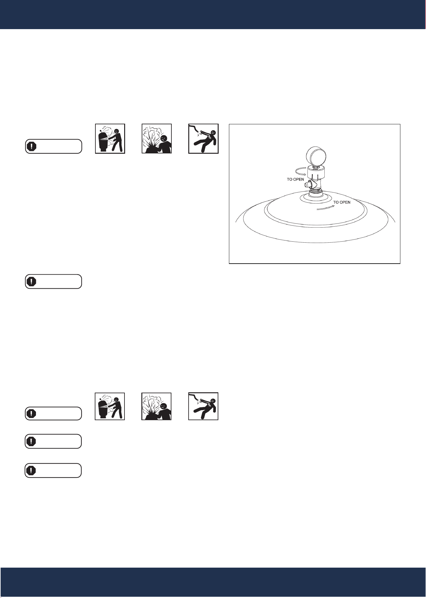
REMOVING THE MANUAL AIR RELIEF VALVE
1. Turn off all system circulation pumps and all electric
power on the equipment pad.
2. Set all system valves to a position that prevents water
from flowing to the filter.
3. The manual air relief valve (MAR) must be placed in
the OPEN position (see Fig. 10).
4. Wait until all water leakage has stopped.
5. The air relief valve can be removed by unscrewing the
entire part counterclockwise (see Fig. 10).
WARNING
1. Check the o-ring seals and replace them as needed.
2. With a clean cloth, wipe the upper filter body and o-ring groove removing all dirt and debris.
3. Align the notch in the MAR flange with the notch on the top of the upper filter body.
4. Press the MAR straight down into the upper filter body.
5. Turn the MAR clockwise until the indicator is aligned with the 'LOCK' position on the upper filter body.
6. Verify that the MAR discharge points away from all electrical connections.
WINTERIZING FILTER
WARNING
1. The filter should be disassembled, and the filter elements cleaned or replaced.
2. Follow the directions under Filter Disassembly Instructions.
3. Then, follow the Removing Filter Element Cluster instructions.
4. Reassemble according to the Filter Reassembly Instructions.
5. Be sure to leave the drain plug unattached during the winter season to avoid cracking the filter body.
19
SERVICE AND REPAIRS
TROUBLESHOOTING
SUGGESTED POOL WATER CHEMISTRY
PH
TOTAL ALKALINITY
CALCIUM HARDNESS
COMBINED CHLORINE
CHLORINE (Stabilized)
CHLORINE STABILIZER (Cyanuric Acid)
7.2 To 7.8
80 To 120 ppm
200 To 400 ppm
0.2 ppm Maximum
1.0 To 3.0 ppm
60 To 80 ppm
LOW WATER FLOW
SHORT FILTER CYCLES
POOL WATER WON’T CLEAR UP
RE
M
E
D
Y
1. Check the element cluster and pump strainer
basket for debris.
2. Check for restrictions in the intake and
discharge lines.
3. Check for air leaks in the intake line, indicated
by bubbles returning to the pool.
1. Check for algae in the pool and superchlorinate
as required.
2. Ensure that chlorine and pH levels are within
the proper range (adjust as required)
1. Check chlorine, pH, and total alkalinity levels,
and adjust as required.
2. Ensure the flow rate through the filter is suffi-
cient.
3. Operate the filter for longer periods if neces-
sary.
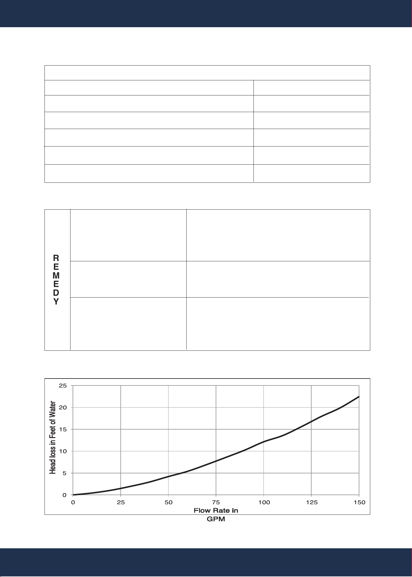
HEAD LOSS
MAINTENANCE
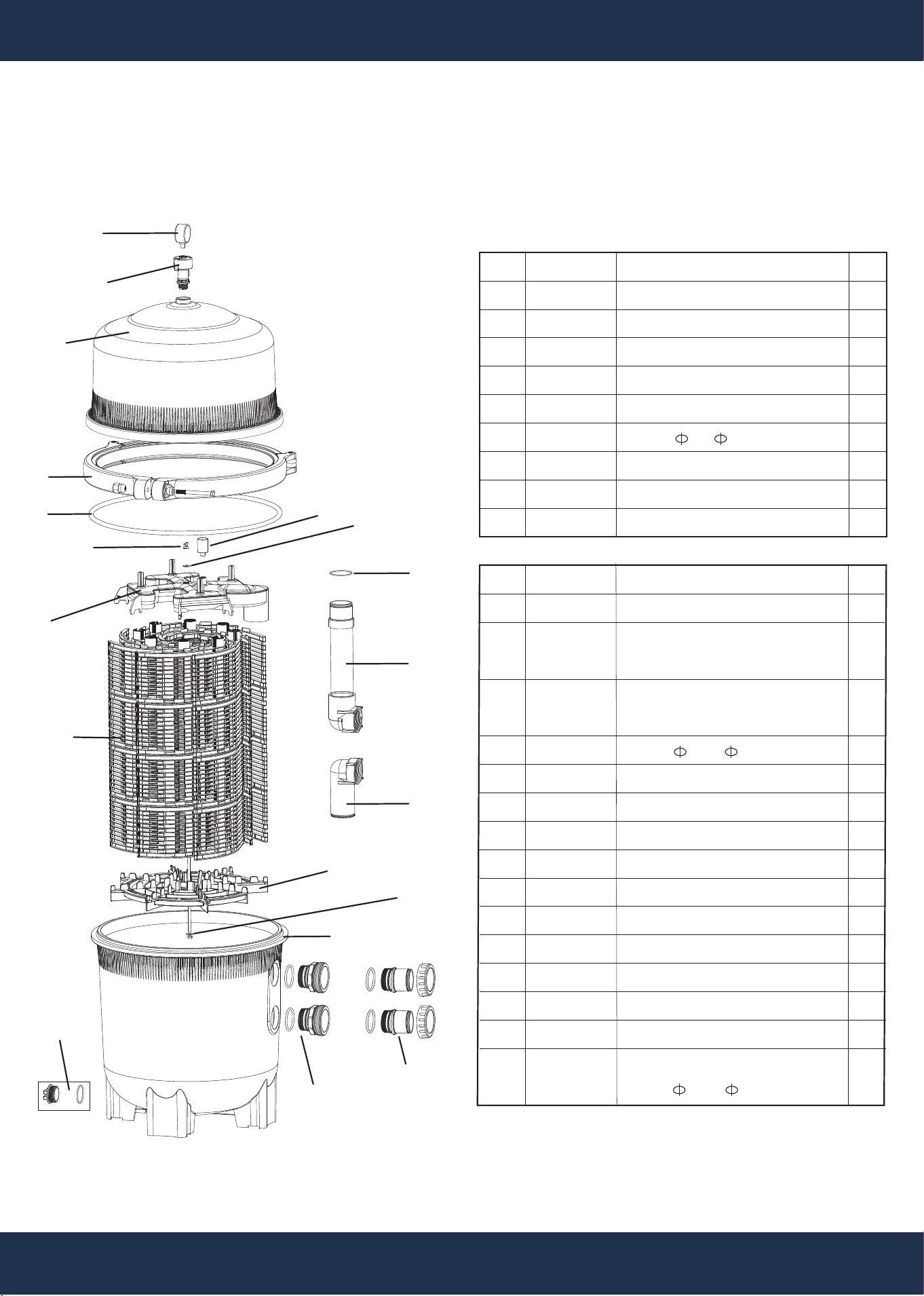
REPLACEMENT PARTS
20
ITEM
1
2
3a
3b
4
5
6
7
8
PARTS NO.
5024015000
647311973000
47311901080
47311905080
647311971000
65431146080
5233042000
65758083000
5244060000
DESCRIPTION
PRESSURE GAUGE
MANUAL AIR RELIEF ASSEMBLY
UPPER FILTER BODY - SKU 75206
UPPER FILTER BODY - SKU 75205
CLAMP SYSTEM
O-RING 490* 12
RETAINER NUT M8
AIR RELIEF FILTER
SEAL D9*8.5
QTY
1
1
1
1
1
1
1
1
2
REPLACEMENT PARTS
PARTS DIAGRAM
ITEM
9
10a
10b
11
12a
12b
13
PARTS NO.
647312512001
647312571001
647312572001
65431073080
647312581001
647312581000
647311908001
DESCRIPTION
TOP COLLECTOR MANIFOLD
FILTER ELEMENT CLUSTER
H=700mm - SKU 75206
FILTER ELEMENT CLUSTER
H=910mm - SKU 75205
O-RING 53.64* 2.62
OUTLET PIPE ASSEMBLY - SKU 75206
OUTLET PIPE ASSEMBLY - SKU 75205
SHORT CIRCUIT
QTY
1
1
1
1
1
1
1
1
1
14
15a
15b
16
17
18a
18b
19
47312507080
5227065000
5227066000
647312524080
647312580000
647312579001
647312579000
91215001
1
1
1
1
2
2
2
1
FILTER ELEMENT LOCATOR
SHORT BOLT - SKU 75206
LONG BOLT - SKU 75205
LOWER FILTER BODY
FITTING
INLET & OUTLET ASSEMBLY - SKU 75206
INLET & OUTLET ASSEMBLY - SKU 75205
1 1/2” DRAIN PLUG WITH O-RING
O-RING 44.04* 3.53
1
2
3a
3b
4
5
6
7
8
9
11
12a
12b
10a
10b
14
15a
15b
16
17
18a
18b
19
13

DISCLAIMER
PLEASE READ THE FOLLOWING CAREFULLY
The manufacturer and/or distributor have provided the parts list and assembly diagram in this manual for reference
purposes only. They do not make any representation or warranty to the buyer that they are qualified to make
repairs to the product or replace any parts of the product. In fact, the manufacturer and/or distributor expressly
state that all repairs and parts replacements should be undertaken by certified and licensed technicians, and not
by the buyer.
The buyer assumes all risk and liability arising from their repairs to the original product or replacement parts or
arising from their installation of replacement parts. It is strongly advised that qualified professionals handle any
repairs or replacements to ensure safety and proper functioning of the product. Improper installation and operation
may result in injury, property damage, or voiding of warranty. The manufacturer and/or distributor shall not be held
responsible for any accidents, damages, or malfunctions resulting from the buyer's installation and operation of
the product. It is essential to follow all safety guidelines and recommendations provided in this manual and to seek
professional assistance if unsure about the installation or operation procedures.
CUSTOMER SERVICE
If you have any questions about ordering our pool pumps and replacement parts or pool products, please
feel free to contact us using the following contact information:
Customer Service and Technical Support
Phone: (909) 628-0880
Email: [email protected]
Hours of Operation: Monday – Friday, 9AM – 4PM (CST)
21
DISCLAIMER
