1
IMPORTANT SAFETY INSTRUCTIONS
1) SAVE THESE INSTRUCTIONS – This manual contains important safety and operating
instructions for battery charger models P/N 021-0133, 021-0134.
2) Do not expose charger to rain or snow.
3) Use of an attachment not recommended or sold by the battery charger manufacturer may
result in a risk of fire, electric shock, or injury to persons.
4) To reduce risk of damage to electric plug and cord, pull by plug rather than cord when
disconnecting charger.
5) An extension cord should not be used unless absolutely necessary. Use of improper
extension cord could result in a risk of fire and electric shock. If an extension cord must
be used, make sure:
a) That pins on plug of extension cord are the same number, size, and shape as those of
plug on charger;
b) That extension cord is properly wired and in good electrical condition; and
c) That wire size is large enough for ac ampere rating of charger as specified in Table 1
6) Do not operate charger with damaged cord or plug – replace the cord or plug
immediately.
7) Do not operate charger if it has received a sharp blow, been dropped, or otherwise
damaged in any way; take it to a qualified serviceman.
8) Do not disassemble charger; take it to a qualified serviceman when service or repair is
required. Incorrect reassembly may result in a risk of electric shock or fire.
9) To reduce risk of electric shock, unplug charger from outlet before attempting any
maintenance or cleaning. Turning off controls will not reduce this risk.
10) WARNING – RISK OF EXPLOSIVE GASES.
a) WORKING IN VICINITY OF A BATTERY IS DANGEROUS. BATTERIES
GENERATE EXPLOSIVE GASES DURING NORMAL BATTERY OPERATION.
FOR THIS REASON, IT IS OF UTMOST IMPORTANCE THAT YOU FOLLOW THE
INSTRUCTIONS EACH TIME YOU USE THE CHARGER.
b) To reduce risk of battery explosion, follow these instructions and those published by
battery manufacturer and manufacturer of any equipment you intend to use in
vicinity of battery. Review cautionary marking on these products and on engine.
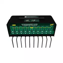
Deltran Battery Tender
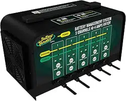
6V/12V 4Amp 5 & 10 Bank Battery Management System
Designed for Six-cell and three-cell Flooded/AGM/GEL Lead-Acid Batteries and
Four-Cell Lithium Iron Phosphate (LiFePO4) Batteries
TABLE 1
Length of Cord, Feet 25 50 100 150
AWG Size of Cord 18 18 18 16
Manual P/N 392-0386-R0
2
11) PERSONAL PRECAUTIONS
a) Consider having someone close enough by to come to your aid when you work near
a battery.
b) Have plenty of fresh water and soap nearby in case battery acid contacts skin,
clothing, or eyes.
c) Wear complete eye protection and clothing protection. Avoid touching eyes while
working near battery.
d) If battery acid contacts skin or clothing, wash immediately with soap and water. If
acid enters eye, immediately flood eye with running cold water for at least 10
minutes and get medical attention immediately.
e) NEVER smoke or allow a spark or flame in vicinity of battery or engine.
f) Be extra cautious to reduce risk of dropping a metal tool onto battery. It might spark
or short-circuit battery or other electrical part that may cause explosion.
g) Remove personal metal items such as rings, bracelets, necklaces, and watches
when working with a battery. A battery can produce a short-circuit current high
enough to weld a ring or the like to metal, causing a severe burn.
h) Use charger for charging Lead-Acid/AGM/Lithium Iron Phosphate batteries only.
It is not intended to supply power to a low voltage electrical system. Do not use
battery charger for charging non-rechargeable batteries that are commonly used
with home appliances. These batteries may burst and cause injury to persons and
damage to property.
i) NEVER charge a frozen battery.
12) PREPARING TO CHARGE
a) If necessary to remove battery from vehicle to charge, always remove grounded
terminal from battery first. Make sure all accessories in the vehicle are off, so as not
to cause an arc.
b) Be sure area around battery is well ventilated while battery is being charged.
c) Clean battery terminals. Be careful to keep corrosion from coming in contact with
eyes.
d) Add distilled water in each cell until battery acid reaches level specified by battery
manufacturer. Do not overfill. For a battery without removable cell caps, such as
valve regulated lead acid batteries, carefully follow manufacturer’s recharging
instructions.
e) Study all battery manufacturers specific precautions such as removing or not
removing cell caps while charging and recommended rates of charge.
f) Determine voltage of battery by referring to car owner’s manual and make sure that
output voltage selector switch is set at correct voltage. Do not use the battery
charger unless battery voltage matches the output voltage rating of the charger.
13) CHARGER LOCATION
a) Locate charger as far away from battery as dc cables permit.
b) Never place charger directly above battery being charged; gases from battery will
corrode and damage charger.
c) Never allow battery acid to drip on charger when reading electrolyte specific gravity
or filling battery.
d) Do not operate charger in a closed-in area or restrict ventilation in any way.
e) Do not set a battery on top of charger.
14) DC CONNECTION PRECAUTIONS
a) Connect and disconnect dc output clips only after setting any charger switches to
offposition and removing ac cord from electric outlet. Never allow clips to touch
each other.
b) Attach clips to battery and chassis as indicated in 15(e), 15(f), and 16(b) through
16(d).
3
15) FOLLOW THESE STEPS WHEN BATTERY IS INSTALLED IN VEHICLE. A SPARK
NEAR BATTERY MAY CAUSE BATTERY EXPLOSION. TO REDUCE RISK OF A
SPARK NEAR BATTERY:
a) Position ac and dc cords to reduce risk of damage by hood, door, or moving engine
part.
b) Stay clear of fan blades, belts, pulleys, and other parts that can cause injury to
persons.
c) Check polarity of battery posts. POSITIVE (POS, P, +) battery post usually has
larger diameter than NEGATIVE (NEG, N,–) post.
d) Determine which post of battery is grounded (connected) to the chassis. If negative
post is grounded to chassis (as in most vehicles), see (e). If positive post is
grounded to the chassis, see (f).
e) For negative-grounded vehicle, connect POSITIVE (RED) clip from battery charger
to POSITIVE (POS, P, +) ungrounded post of battery first. Then connect NEGATIVE
(BLACK) clip to vehicle chassis or engine block away from battery. Do not connect
clip to carburetor, fuel lines, or sheet-metal body parts. Connect to a heavy gage
metal part of the frame or engine block.
f) For positive-grounded vehicle, connect NEGATIVE (BLACK) clip from battery
charger to NEGATIVE (NEG, N, –) ungrounded post of battery first. Then connect
POSITIVE (RED) clip to vehicle chassis or engine block away from battery. Do not
connect clip to carburetor, fuel lines, or sheet-metal body parts. Connect to a heavy
gage metal part of the frame or engine block.
g) When disconnecting charger, turn switches to off, disconnect AC cord, remove clip
from vehicle chassis, and then remove clip from battery terminal.
h) See operating instructions for length of charge information.
16) FOLLOW THESE STEPS WHEN BATTERY IS OUTSIDE VEHICLE. A SPARK NEAR
THE BATTERY MAY CAUSE BATTERY EXPLOSION. TO REDUCE RISK OF A
SPARK NEAR BATTERY:
a) Check polarity of battery posts. POSITIVE (POS, P, +) battery post usually has a
larger diameter than NEGATIVE (NEG, N, –) post.
b) Attach at least a 24-inch-long 6-gauge (AWG) insulated battery cable to NEGATIVE
(NEG, N, –) battery post.
c) Connect POSITIVE (RED) charger clip to POSITIVE (POS, P, +) post of battery.
d) Position yourself and free end of cable as far away from battery as possible – then
connect NEGATIVE (BLACK) charger clip to free end of cable.
e) Do not face battery when making final connection.
f) When disconnecting charger, always do so in reverse sequence of connecting
procedure and break first connection while as far away from battery as practical.
g) A marine (boat) battery must be removed and charged on shore. To charge it on
board requires equipment specially designed for marine use.
This symbol indicates separate collection for electrical and
electronic equipment
4
USER INSTRUCTIONS
Battery Charger Functions:
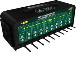
This Battery Management System has either 5 or 10 charging stations.
Each one of these stations is totally independent of all others when it
comes to charging and maintaining the battery that it is connected to.
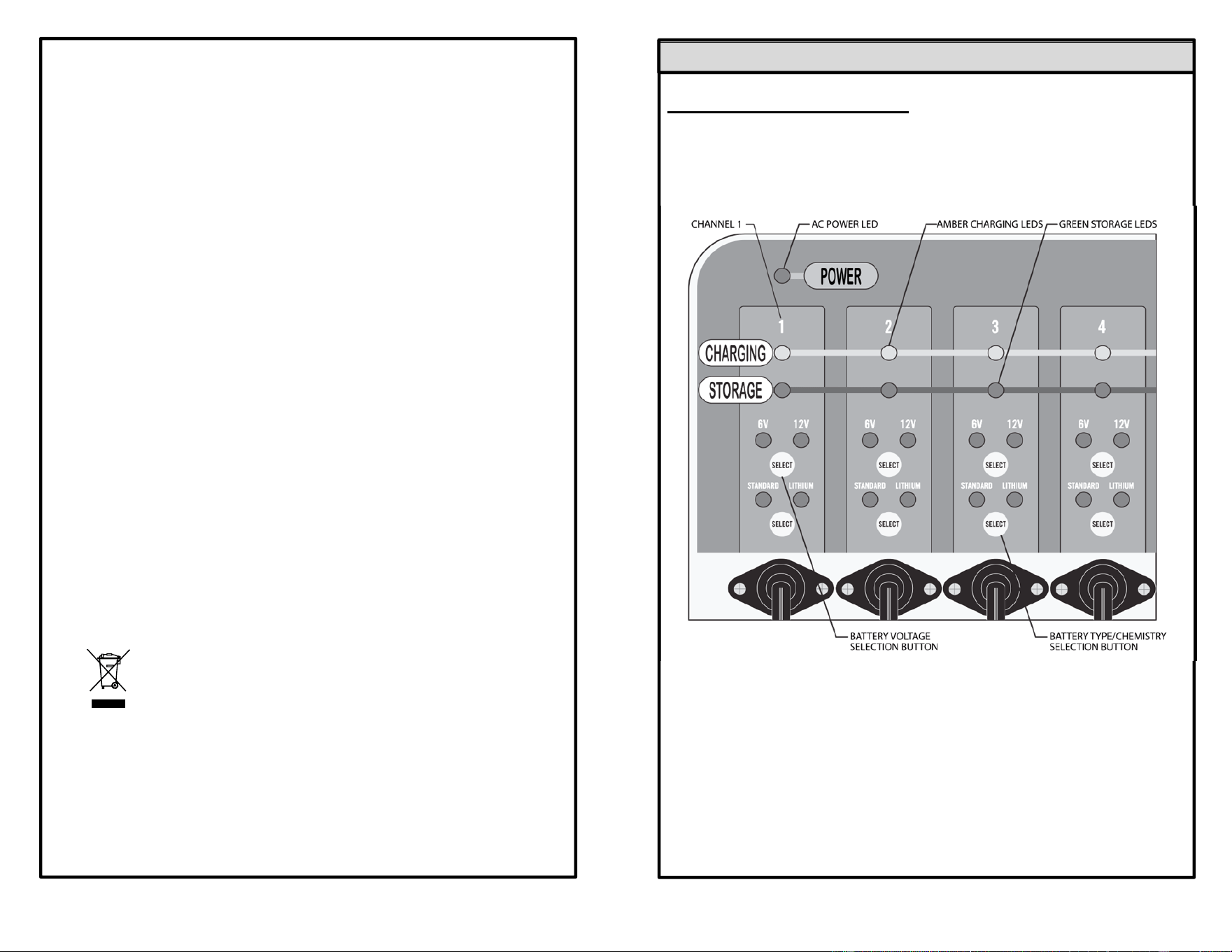
FRONT OF CHARGER
5
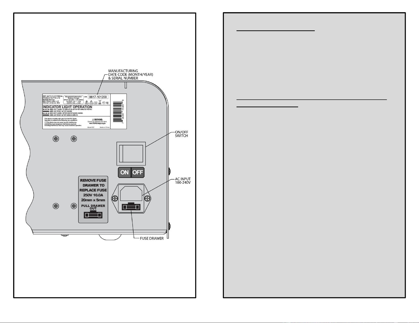
BACK OF CHARGER
6
Powering Up the Charger:
1) When the On/Off switch, located on the back of the charger, is
activated into the ON position, the AC Power LED on the front of
the charger will illuminate and remain on.
2) All of the individual channel LED’s will also illuminate for
approximately 1½ seconds before turning off.
3) The charger is now ready to be connected to the
battery/batteries.
Connecting to a Battery/Batteries and Starting the
Charging Sequence:
1) When a channel is connected to a battery, the Charging LED
and the Storage LED for that channel will illuminate for
approximately 1½ seconds before turning off.
2) The four LED’s for the 6V/12V mode and the Standard/Lithium
mode will also activate for approximately 1½ seconds. Then the
two (2) non-active mode LED’s will turn off and the two (2) active
mode LED’s will start to flash.
3) You now have approximately ten (10) seconds to change the
6V/12V and Standard/Lithium active mode, if required, before
the charging cycle automatically begins.
4) After approximately ten seconds, the amber Charging LED will
automatically illuminate and the charge cycle will begin.
5) Once the charge cycle is in progress, neither the voltage mode
nor chemistry mode can be changed unless the battery is
disconnected from the charger (see the next sections for
information on how to change the active mode of either
function).

7
Battery Voltage (6V/12V) Selection Button:
1) The Battery Tender® charger has a “SELECT” button for each
channel which allows you to switch between charging a 12-volt
Standard/AGM Lead-acid or 12-volt Lithium Iron Phosphate
(LiFePO4) battery or a 6-volt Standard/AGM Lead-acid battery.
Note: For Lithium chemistry compatibility, this charger will only
charge 12-volt rated Lithium Iron Phosphate (LiFePO4)
batteries.
2) If the AC power is interrupted, all charger channels connected to
batteries will resume charging with the last battery voltage
settings used, once power is restored.
3) The charger can also detect if the incorrect battery voltage has
been selected or if the battery is defective, once the connection
has been made to the battery. Under these conditions, either the
6V or 12V LED will flash, indicating the charge cycle is
prevented from starting or continuing.
4) To reset the faulted charger channel, disconnect the output
cable from the battery and then depress the select switch for the
flashing LED function for approximately 5 seconds.
5) All of the LED’s for the faulted channel will then turn off.
6) Reconnect the output cable to the battery and repeat step three
(3) as stated in the
Connecting to a Battery/Batteries
and Starting the Charging Sequence section. (page 6)
Battery Type/Chemistry Selection Button:
1) The Battery Tender® charger has a “SELECT” button for each
channel which allows you to switch between charging a
Standard/AGM Lead-acid battery or a Lithium Iron Phosphate
battery (12-Volt only LiFePO4).
Note: For Lithium chemistry compatibility, this charger will only
charge 12-volt rated Lithium Iron Phosphate (LiFePO4)
batteries.
2) If the AC power is interrupted, all charger channels connected to
batteries will resume charging with the last battery chemistry
settings used, once power is restored.
3) To reset the charger channel after a charge cycle has begun or
change the active mode, disconnect the output cable from the
battery.
4) All of the LED’s for that channel will then turn off.
8
5) Reconnect the output cable to the battery and repeat step three
(3) as stated in the
Connecting to a Battery/Batteries
and Starting the Charging Sequence section.
●
Automatic Lithium Iron Phosphate (LifePO4)
Recovery Mode:
If you try to charge a dead 12-volt Lithium Iron Phosphate battery
(LiFePO4) with a very low voltage, 4 to 8 Volts, the charger will
automatically switch into the Recovery Mode. When in this mode,
the Lithium LED will flash and the 12V LED and the amber Charging
LED will be solid. If battery recovery is successful, the charger will
automatically switch back to the normal charge cycle.
There is a three (3) hour time limit for this recovery process. If not
successful, the Charging amber LED and the Storage green LED will
toggle back and forth. It will continue this sequence until the battery
is disconnected and the voltage select button is depressed for
approximately five seconds, or the charger is disconnected from the
AC source. If this happens, there is a good chance that the battery
has already been damaged due to the low voltage and cannot be
recovered.
●
Power LED:
When the On/Off switch located on the back of the charger is
activated into the ON position, the AC power LED on the front will
illuminate and remain on.
● Battery Safety Timer:
The charger has a safety timer fault that will activate if the battery
does not reach its optimal voltage. If this occurs the battery may be
defective; take the battery to the dealer to be tested.
In this fault mode, the Amber Charging and Green Storage LED’s
will toggle back and forth.
To reset the charger channel, disconnect the battery and hold down
the Voltage select button for approximately five seconds, or
disconnect the charger from the AC source.
●
Charger Cooling Fan Operation:
The fan is electronically controlled and will turn on when the charger
reaches a preset temperature or a preset amperage output level.
The fan will continue to run and adjust its speed to keep the charger
at the correct temperature. The fan will also turn off automatically
once the correct temperature has been reached. Always leave an
open space at both ends of the charger to allow the fan to pull air
into and through the charger and exit at the opposite end. The fan
contains a filter which can be removed and cleaned by simply

9
removing the fan guard from the charger cover. REMOVE the AC
plug from the power source before attempting this procedure.
● Automatic Charging And Battery Status Monitoring:
Battery Tender® Shop chargers are completely automatic and may
be left connected to both AC power and to the batteries being
charged for long periods of time. The output power, voltage, and
current of each channel depends on the condition of the battery it is
charging. Battery Tender
®
chargers have several status LED
indicators that provide a visual means to determine the operating
mode of the charger and, hence, the condition of the battery
connected to the charger.
The two battery level status LED indicator lights (Charging Amber
LED and Storage Green LED) are available to determine whether
the charger is operating in one of the four primary charge modes:
1) Qualification/Initialization mode- The Monitor Circuit verifies
appropriate battery voltage levels and good electrical continuity
between the battery and the charger DC output.
2) Bulk mode- (full charge, constant current, battery is 0% to 80%
charged)
3) Absorption mode- (high constant voltage, battery is 80% to
100% charged).
4) Storage/float maintenance mode- (low constant voltage,
battery is 100% to 103% charged).
When the battery is fully charged, the battery level status (Storage)
Green LED indicator will turn solid green and the charger will switch
to a storage/float maintenance charge mode. The Battery Tender
®
charger will automatically monitor and maintain the battery at full
charge.
●
Attention: The Battery Tender
®
Charger Has Spark
Free Circuitry:
The Battery Tender
®
charger will not produce an output voltage until
it senses at least 2 volts from a Standard/AGM Lead acid battery or
4 volts from a Lithium Iron Phosphate battery. It must also be
connected to a battery with the correct polarity before it will start
charging. Therefore, if the output cable alligator clips incidentally
come in contact with one another, there will be no electrical spark.
NOTE:
THE OUTPUT CLIPS MUST BE CONNECTED TO A BATTERY
BEFORE THE CHARGER CAN PRODUCE AN OUTPUT VOLTAGE.
10
● Time Required To Charge A Battery:
Each channel of this Battery Tender
®
Shop charger charges at a
maximum rate of 4.0 Amps per hour. Therefore, at 4.0 Amps, a fully
discharged 12V 40 Amp-Hour battery will take approximately 8
hours to recharge to 80% capacity.
●
Working With a Dead Battery or a Battery with a Very
Low Voltage:
If you try to charge a dead battery having a voltage below 2 volts
from a Standard/AGM Lead-acid battery or 4 volts from a Lithium
Iron Phosphate battery, the Battery Tender
®
charger will not start. An
internal safety circuit prevents the charger from generating any
output voltage unless it senses at least 2 volts from a Standard/AGM
Lead-acid battery or 4 volts from a Lithium Iron Phosphate battery at
the charger output.
NOTE:
If a 12-Volt Lead-Acid battery has an output voltage of less than 9
volts when it is at rest, when it is neither being charged nor
supplying electrical current to an external load, there is a good
chance that the battery is defective. As a frame of reference, a fully
charged 12-Volt, Lead-Acid battery will have a rest-state, no-load
voltage of approximately 12.9 volts. A fully discharged 12-Volt,
Lead-Acid battery will have a rest-state, no-load voltage of
approximately 11.4 volts. That means that a voltage change of only
1.5 volts represents the full range of charge 0% to 100% on a 12-
Volt, Lead-Acid battery. Depending on the manufacturer and the age
of the battery, the specific voltages will vary by a few tenths of a volt,
but the 1.5-volt range will still be a good indicator of the battery
charge %.

11
●
LED Status Indicating Lights:
Charger Power Amber Light Not On:
- A/C On/Off switch not in correct position.
- Power cord not connected to A/C power.
- A/C power fuse defective.
Voltage/Chemistry Mode Lights Not On:
This indicates one or more of the following conditions.
- Channel output cable not sufficiently connected to the battery.
- Channel output cable fuse defective.
- Battery voltage extremely low.
- No or insufficient A/C power supplied to charger.
- Channel defective.
Alternating Storage Green & Charging Amber
Light:
This indicates one or more of the following conditions.
- A reversed polarity connection to the battery.
- Battery Lithium Recovery Mode time limit exceeded.
- Bulk Charge Mode time limit exceeded.
• Charging Amber Light On Steady:
Whenever the amber Charging LED is on steady, a battery is
connected properly and the charger is charging the battery. The
amber LED will remain on until the charger completes the
charging stage.
Storage Green Light Flashing:
When the green Storage LED is flashing and the Amber
Charging LED is solid, the battery is greater than 80% charged
and may be removed from the charger and used if necessary.
Whenever possible, leave the battery on charge until the green
Storage LED is solid.
Storage Green Light on Steady:
When the green Storage LED burns steady, the charge is
complete and the battery can be returned to service if
necessary. It can also stay connected to maintain the battery for
an indefinite period of time.
12
Troubleshoot Guide:
1) The charger does not turn on and none of the LED’s illuminate.
a. Check to make sure the AC outlet is supplying power by
plugging in a lamp, an appliance, or a voltage meter.
b. Check the fuse located on the back of the charger.
2) The Green Storage LED comes on immediately when charging
a discharged battery.
a. The battery is probably defective; take the battery to the
dealer to be tested.
3) The Green Storage LED never comes on when charging a
battery.
a. The battery may be defective; take the battery to the
dealer to be tested.
b. The battery has an excessive current draw; remove or
disconnect the battery from the equipment.
4) 12V Green LED is flashing.
a. The battery is damaged.
b. Incorrect battery voltage is selected.
5) 6V Green LED is flashing.
a. The battery is damaged.
b. Incorrect battery voltage is selected.
6) Amber Charging & Green Storage LED’s are toggling.
a. There is a reverse polarity connection to the battery.
b. The charger’s safety timer has expired due to the
battery not reaching its optimal voltage. The battery may
be defective; take the battery to the dealer to be tested.
c. The Lithium Recovery Mode has timed out.

13
●
Warranty:
This product is covered by a 3 Year general limited warranty
DISTRIBUTED BY:
DELTRAN USA LLC.
801 International Speedway Blvd.
Deland, Florida 32724
(386) 736-7900
www.batterytender.com
Battery Charger Radio Frequency Warnings:
FCC WARNING
Title 47 Subpart, 15.105(b)
Note: This equipment has been tested and found to comply with the
limits for a class B digital device, pursuant to part 15 of the FCC
Rules. These limits are designed to provide reasonable protection
against harmful interference in residential installation. This
equipment generates uses and can radiate radio frequency energy
and, if not installed and used in accordance with the instructions,
may cause harmful interference to radio television reception, which
can be determined by tuning the equipment off and on, the user is
encouraged to try to correct the interference by one or more of the
following measures:
- Reorient or relocate the receiving antenna.
- Increase the separation between the equipment and receiver.
- Connect the equipment into an outlet on a circuit different from
that to which the receiver is connected.
Consult the dealer or an experienced radio/TV technician for help
Canadian ICES-001: Industrial, Scientific, and Medical (ISM)
Radio Frequency Generators
This product has been tested with the listed standards and found to
be compliant with the Code of Industry Canada ES-001 and the
measurement Procedure according to CISPR 11.
CAN ICES-1/NMB-1