User
Manual
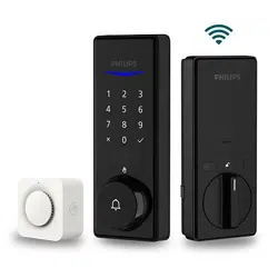
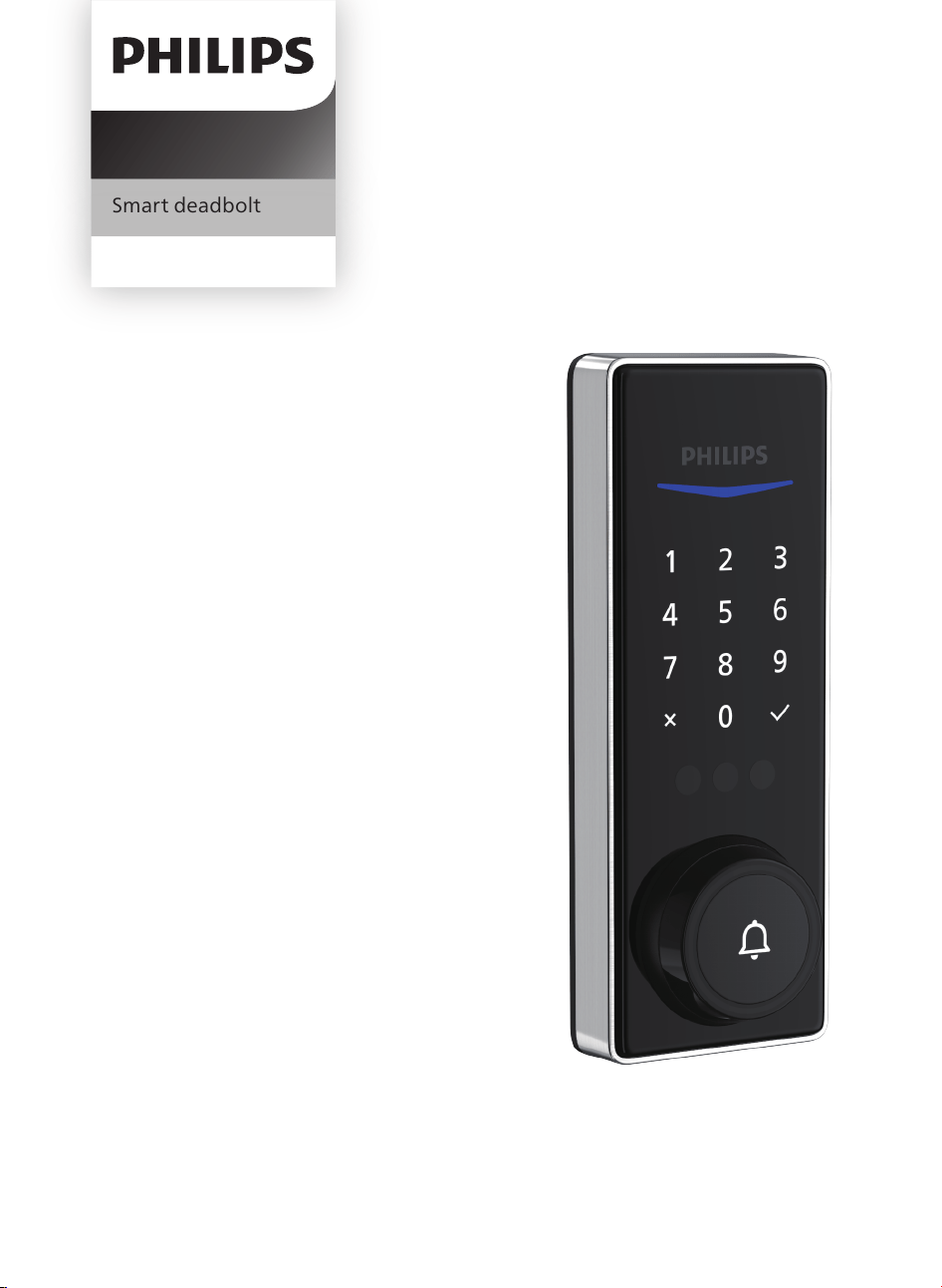
Smart deadbolt
Home Access
Register your product and get
support at www.philips.com/support
5000 series


Contents
1 Warnings & Safety 02
2 How to Install
03
3 How to Setup 13
Parts List
Assembly View
Install the Lock
Install the Door Position Sensor
Download the Philips Home Access App
Create a User Account
Add the Device
Calibrate the Door Position Sensor
Connect to Your Home Wi-Fi Network
6 Troubleshooting
25
4 How to Use 14
Feature De�nitions
Factory Reset & Default Settings
Format of Entry Methods
Add a Palm ID
Unlock with Palm ID
Lock & Unlock
5 Add the Chime 22
Product Overview
Operations & Features
Add the Chime
Safety
Caution
Returns & Disposal
7 Warranty 27
28
9 ISED Statement 29
8 FCC Statement
1

◆ Before using this product, please read and understand all instructions. Damage caused
by failure to follow the instructions is not covered by the warranty.
◆ Only use components the manufacturer provided and suggested accessories.
◆ Only use non-rechargeable CR123A Lithium Batteries.
◆ Do not forcibly disassemble the product to trigger an alarm or damage the product.
◆ Do not scrape the �ngerprint sensor with sharp objects as this may cause permanent
damage.
◆ Do not remove the batteries during lock setup and operation.
◆ Change the default master PIN code immediately via the Philips Home Access app after
completing the installation.
Caution
◆ Do not place the batteries near �re sources.
◆ Do not connect the 2 poles of the batteries to metals to avoid a short circuit and
potential explosion.
◆ Any replacement component should be performed by Philips, a Philips-authorized
service center, or a professional technician.
◆ Do not use parts or accessories manufactured by others, except batteries.
◆ Do not expose products to places that have water leakage or splashing.
Returns & Disposal
◆ Locks can be returned at an authorized Philips service center. Appropriate compensation
will be provided if the returned product meets Philips's conditions.
◆ Please follow local regulations and do not throw the used products or batteries into
normal household waste.
1 Warnings & Safety
Safety
2
2 How to Install
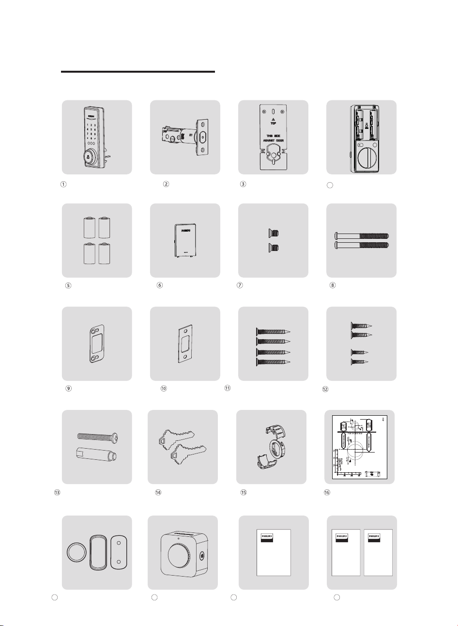
Parts List
User
Manual
Upper Screw & Screw
Post (Optional)
Mounting
Template
Door Position
Sensor
Backup Keys Drive-In Collar Drilling Template
Exterior Assembly Latch Bolt Mounting Plate
CR123A Lithium Battery Cover Interior Assembly
Screws (2)
Mounting Plate
Screws (2)
Reinforcement
Plate (Optional)
Strike Plate
Strike Plate Screws (2)
Latch Bolt Screws (2)
Reinforcement Plate
Screws (2)
(Optional)
Door Position Sensor
Mounting Template
19
User Manual
20
Interior Assembly
4
Door Position Sensor
17
Door Position Sensor Cap
Wireless Chime
18
Door Sensor
Screws (2)
Batteries (4)
Quick Start
Guide
Quick Start Guide
3
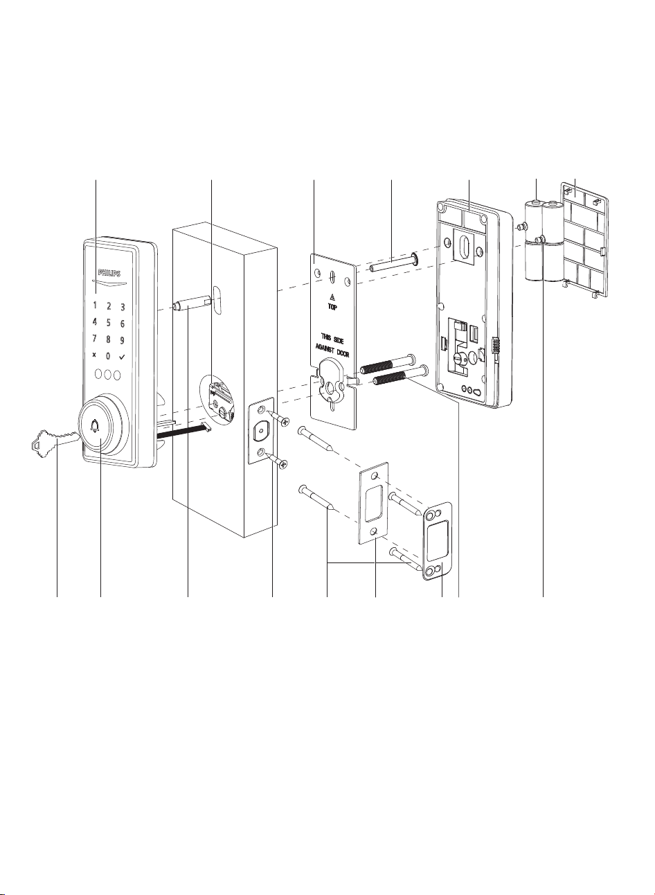
Assembly View
1.
2.
3.
4.
5.
Exterior Assembly
Latch Bolt
Mounting Plate
Interior Assembly
CR123A Lithium Batteries (4)
6. Battery Cover
7. Interior Assembly Screws (2)
8. Mounting Plate Screws (2)
13. Upper Screw and Screw Post (Optional)
14. Keyhole Cover & Doorbell Button
15. Backup Keys (2)
9.
11.
12.
Reinforcement Plate (Optional)
Strike Plate Screws (2)
Reinforcement Plate Screws (Optional) (2)
10. Strike Plate
Latch Bolt Screws (2)
13 (Optional)
13 (Optional)
65
2 3
78101112 9
1
14
4
15
4
Exterior Assembly
Interior Assembly
1
2
3
4
6
5
7
8
9
2
1
3
5
4
6
8
9
7
1
3
2
6
5
4
7
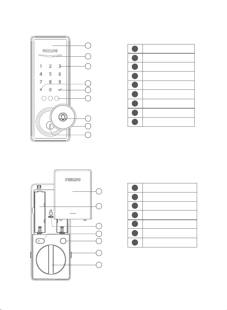
Exterior Proximity Sensor
Status Indicator
Touchscreen Keypad
Cancel Key
Con�rm Key
Palm ID Reader
Doorbell
Keyhole Cover
Keyhole
1
2
3
4
6
5
7
Battery Cover
CR123A Lithium Batteries
Reset Button
Interior Proximity Sensor
Privacy Button
Installation Buckle
Thumb Turn
5
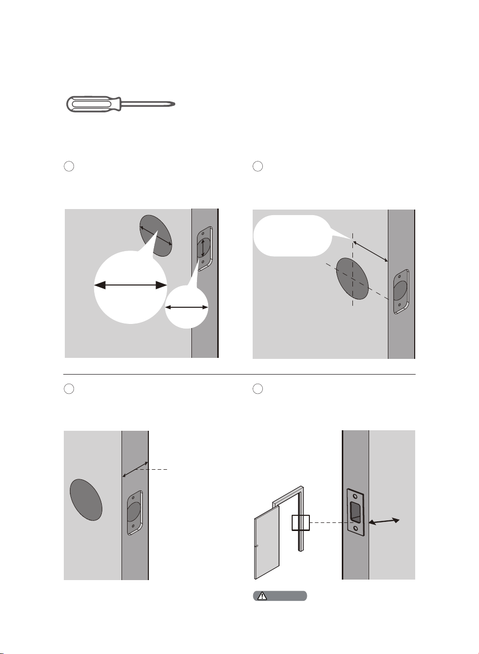
Measure to con�rm that the hole in the
door is 1-1/2’’ or 2-1/8" (38mm or 54mm).
Measure to con�rm that the hole in the
door edge is 1" (25mm).
Install the Lock
1
Measure to con�rm that the backset is
either 2-3/8" or 2-3/4" (60mm or 70mm).
2
1’’
25 mm
Prepare the Door and Check the Dimensions
Required Tools
2-3/8’’ or 2-3/4’’
(60mm or 70mm)
Backset
Measure to con�rm that the door is
1-3/8" to 2" (35mm to 50mm) thick.
3
Make sure the hole in the door frame is
drilled a minimum of 1’’ (25mm) deep to
leave enough space for the deadbolt to
extend into the door frame when the
door is locked.
4
1-3/8’’ to 2’’
(35mm to 50mm)
1’’
25mm
Make sure the door frame is aligned with the door
and there are no obstructions in the door frame.
Attention
1-1/2" or 2-1/8"
(38mm or 54mm)
#2 Phillips Screwdriver
6

If you install this screw, you need to drill a hole (19/32″) in the door before starting the installation.
Drilling Template
OPTIONAL: Drill a hole for Upper Screw.
5
Installing this screw onto the Exterior Assembly is OPTIONAL. It is used for additional security or when a door is weak
or warped.
Attention
7
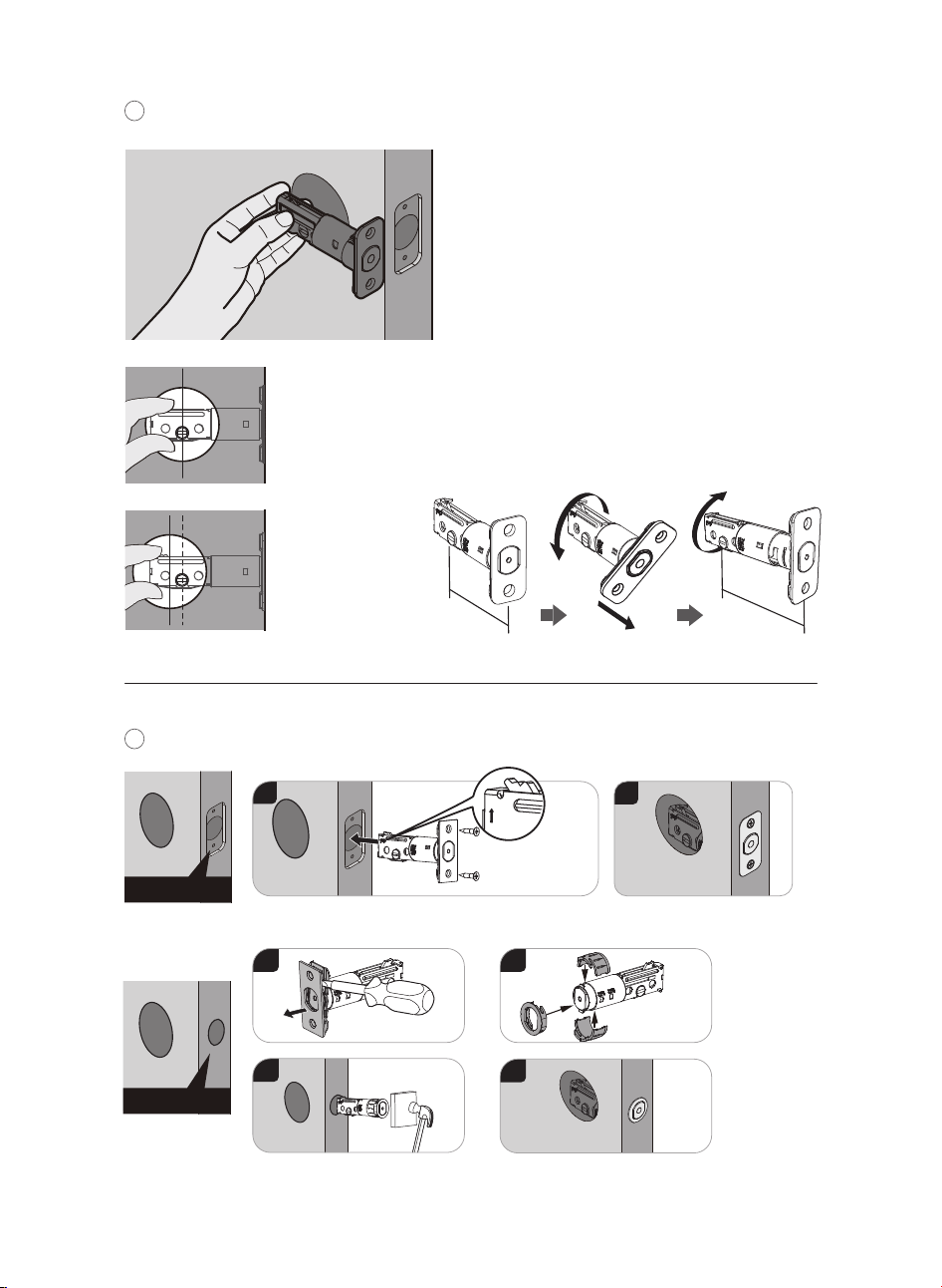
Install the Latch Bolt.
7
Chiseled
Determine the backset and adjust the
Latch Bolt.
6
Hold the Latch Bolt in front of the door hole,
with the Latch Bolt face �ush against the
door edge. Is the slotted hole centered in the
door hole?
No adjustment is
required.
Proceed to the next step.
YES
The slotted hole is
NOT centered.
Rotate and pull the
Latch Bolt as
shown to extend it.
NO
Latch Bolt Screws
1
2
up
2-3/4"
(70mm)
2-3/8"
(60mm)
pull
Not chiseled
Drive-In Collar
1
3
2
4
8
Strike Plate Screws
Make sure the hole in door frame is drilled a minimum
of 1"(25mm) deep.
Use a screwdriver to con�rm that the
deadbolt locks and unlocks smoothly.
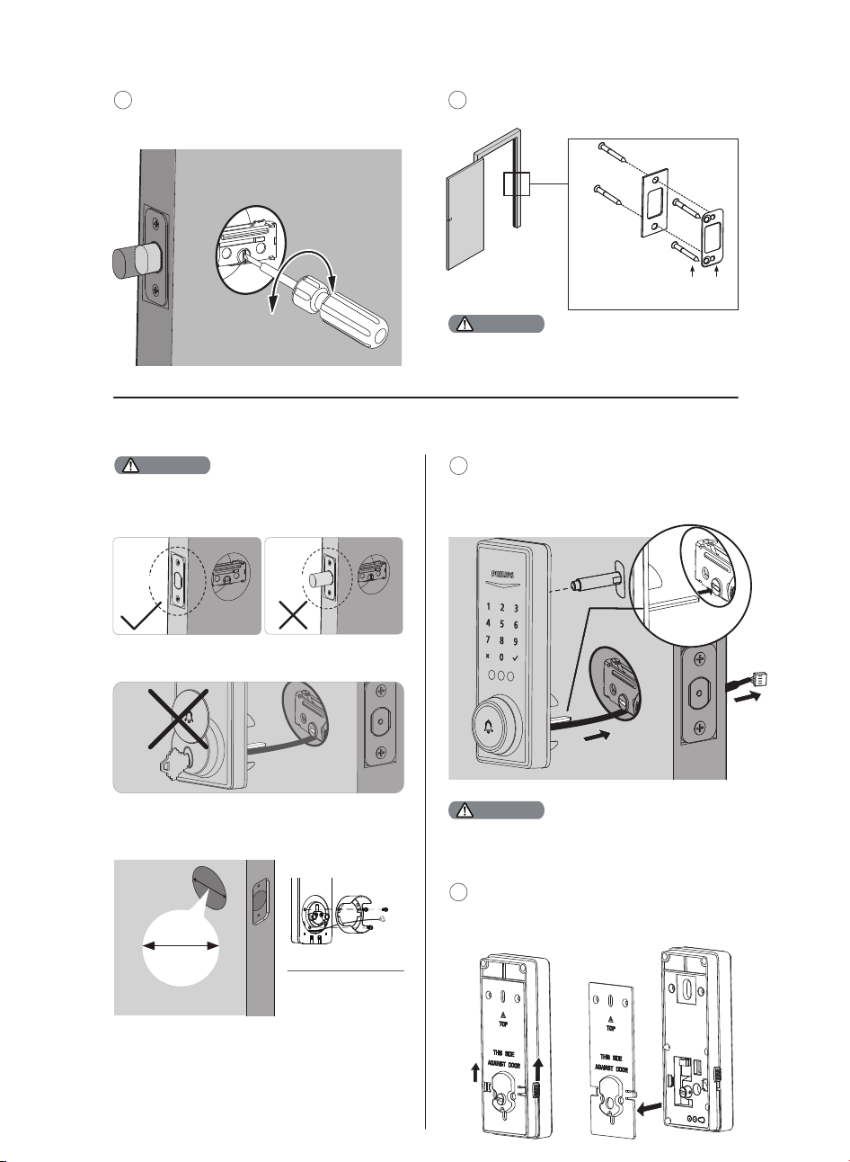
8
Install the Strike Plate on the door frame.
9
Attention
Install the Exterior Assembly
(Optional)
Before installing the Exterior and Interior Assembly,
make sure the Latch Bolt is fully retracted (in the
unlocked position).
Attention
Unlocked
Locked
Measure the diameter of
the hole in the door.
1-1/2" or 2-1/8"
(38 or 54mm)
Remove the spacer
Proceed to next step
1-1/2" (38mm)
2-1/8" (54mm)
Attention
The Upper Screw & Screw Post on the top is OPTIONAL.
It is used for additional security, or when a door is weak
or warped.
10
With the Latch Bolt fully retracted (in the
unlocked position), route the cable below
the Latch Bolt, and insert the tailpiece
through the slot in the Latch Bolt.
Tailpiece
Move the Installation Buckles on both sides of
the Interior Assembly upwards to remove the
Mounting Plate from the interior base.
11
Do not insert the key when you are installing.
9
Do not load batteries before �nishing the lock installation.
Attention
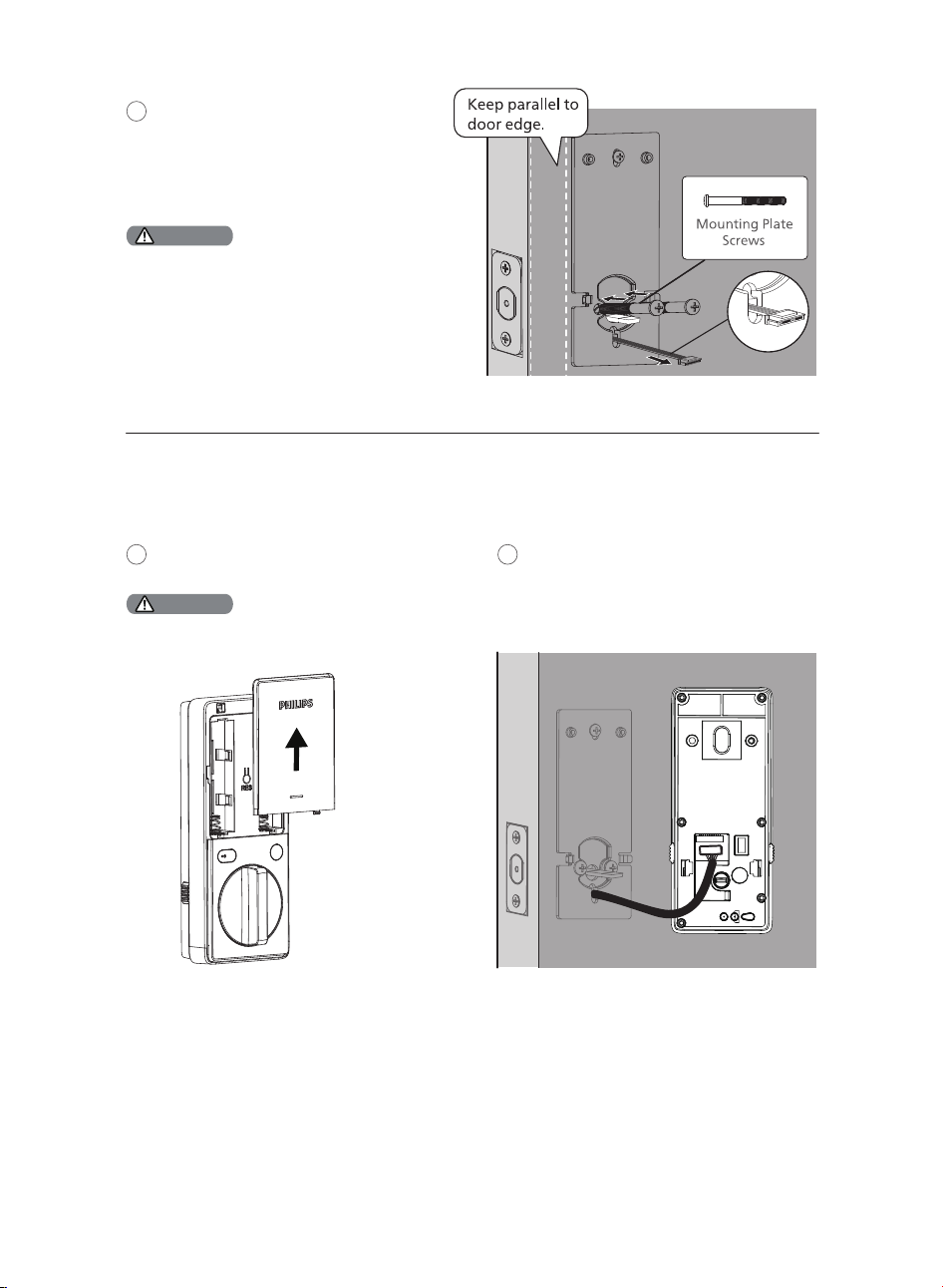
Route the cable through the hole in the Mounting
Plate.
The Upper Screw on the top is OPTIONAL.
Before installing the Upper Screw, fasten the Screw
Post into the hole of the Exterior Assembly.
Push the Battery Cover up in the direction
as illustrated.
13
Insert the cable connector of the Exterior
Assembly to the socket on the Interior
Assembly. Push the connector in �rmly
until it is completely attached.
14
Install the Interior Assembly
Attention
Secure the Mounting Plate with the
Mounting Plate Screws. Do not
overtighten screws.
12
10
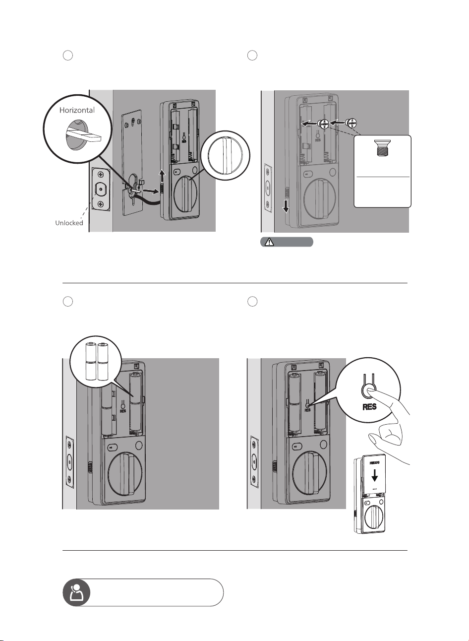
Keep the Thumb Turn in the vertical position,
toggle the Installation Buckle upwards, and
install the Interior Assembly.
15
Attach the Interior Assembly to the Mounting
Plate, toggle the Installation Buckle downwards,
and fasten using the Interior Assembly Screws.
16
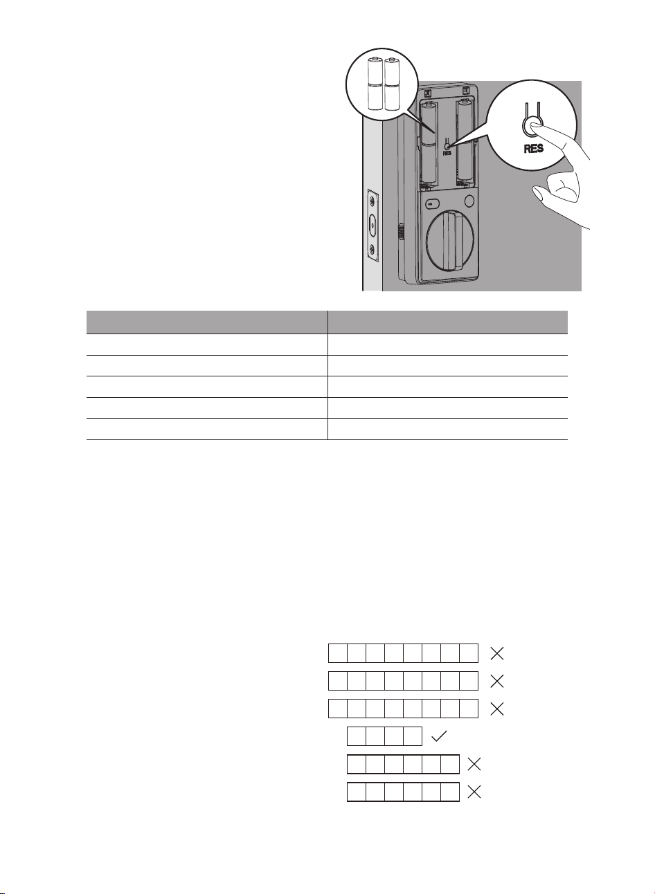
Install the 4 CR123A batteries.
17
Press and hold the Reset Button for at
least 5 seconds until you hear a beep. This
activates the lock-handing process and
must be completed before setting up the
lock.
18
Need help?
U.S.A. & Canada: +1(833)599-9111
Ensure the cable is not pinched or the lock will
not function properly.
Attention
Interior Assembly
Screws
Note:
Do not use
other screws.
11
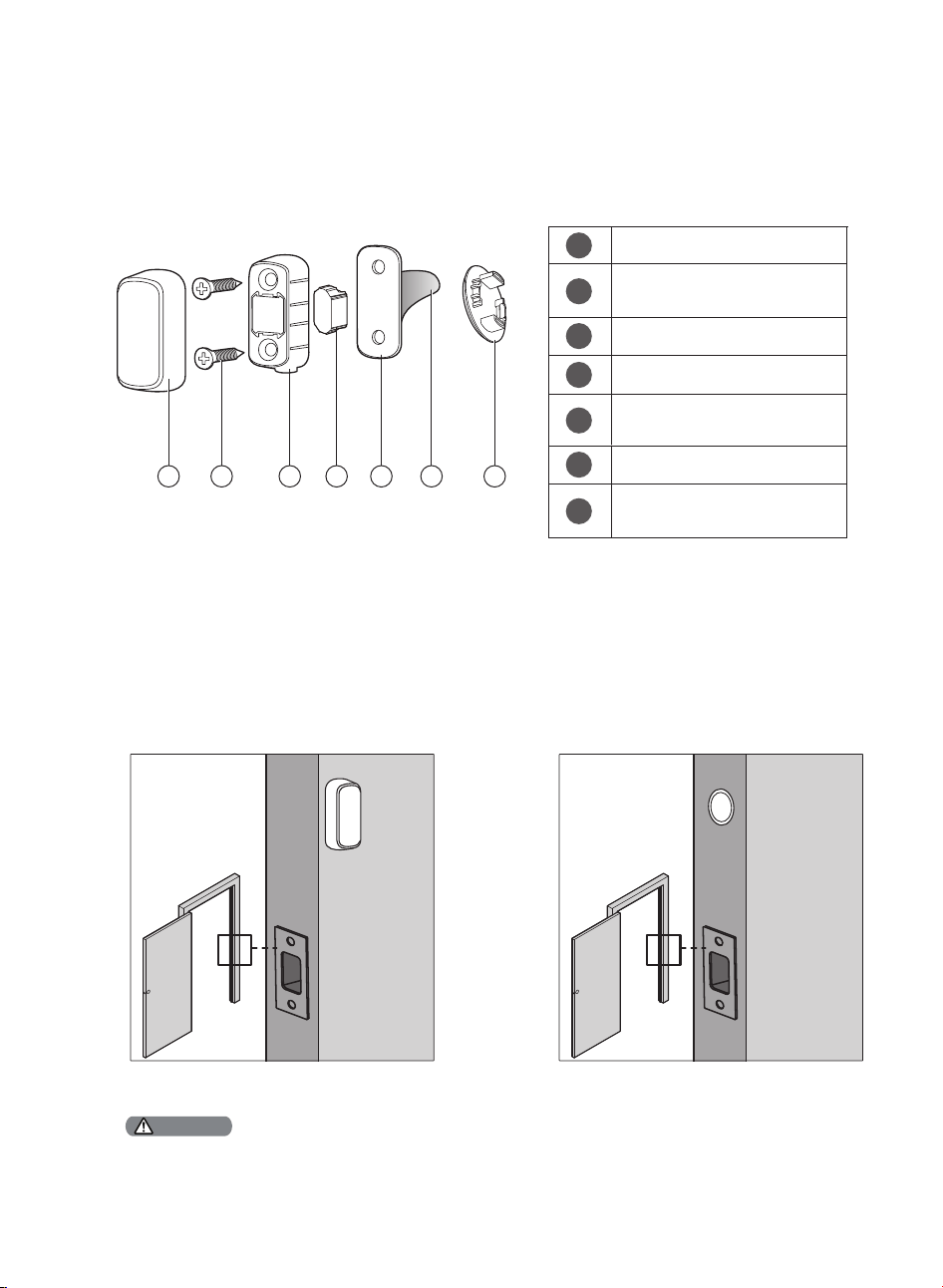
There are two ways to install the Door Position Sensor: Surface Mount and Flush Mount. Refer to the Door
Position Sensor Mounting Template in the box for speci�c operations.
It is recommended to install the Door Position Sensor using the Surface Mount method to avoid drilling
additional holes in your door.
Install the Door Position Sensor
Assembly View
How to Install
Cover
Door Position Sensor
Mounting Screws (Optional) (2)
Mounting Housing
Magnet
1
2
3
4
Door Position Sensor
Mounting Template
5
Mounting Tape
6
Door Position Sensor
Cap (Optional)
7
1 2 3 4 5 6 7
INDOOR
Surface Mount Flush Mount
INDOOR
If you want to use the Door Position Sensor but prefer not to drill into the door frame, install the surface mounted Door
Position Sensor using the Mounting Tape ONLY.
Attention
12
3 How to Setup
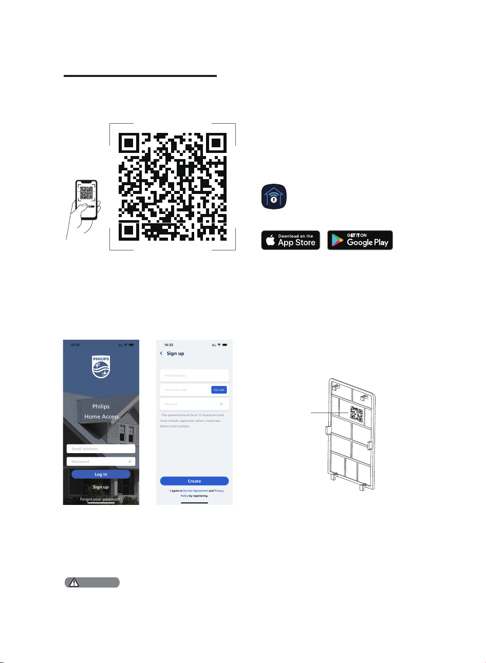
Download the Philips Home Access App
Create a User Account
Register and log in to the Philips Home
Access app.
QR code
Home Access
Add the Device
Enable Bluetooth on your phone and click the
“Add device” button on the app.
Scan the QR Code or manually enter the ESN
located on the back of the Battery Cover and
complete the pairing steps following the in-app
instruction.
Scan the QR Code to download the Philips Home Access app.
QR Code
Calibrate the Door Position Sensor
Follow the instructions in the app until you have successfully calibrated your smart lock and the Door
Position Sensor together.
The process of calibrating the Door Position Sensor should be carried out near the smart lock.
If the Philips Home Access app fails to calibrate the lock, check whether the Door Position Sensor has been installed
correctly and try again.
Attention
13
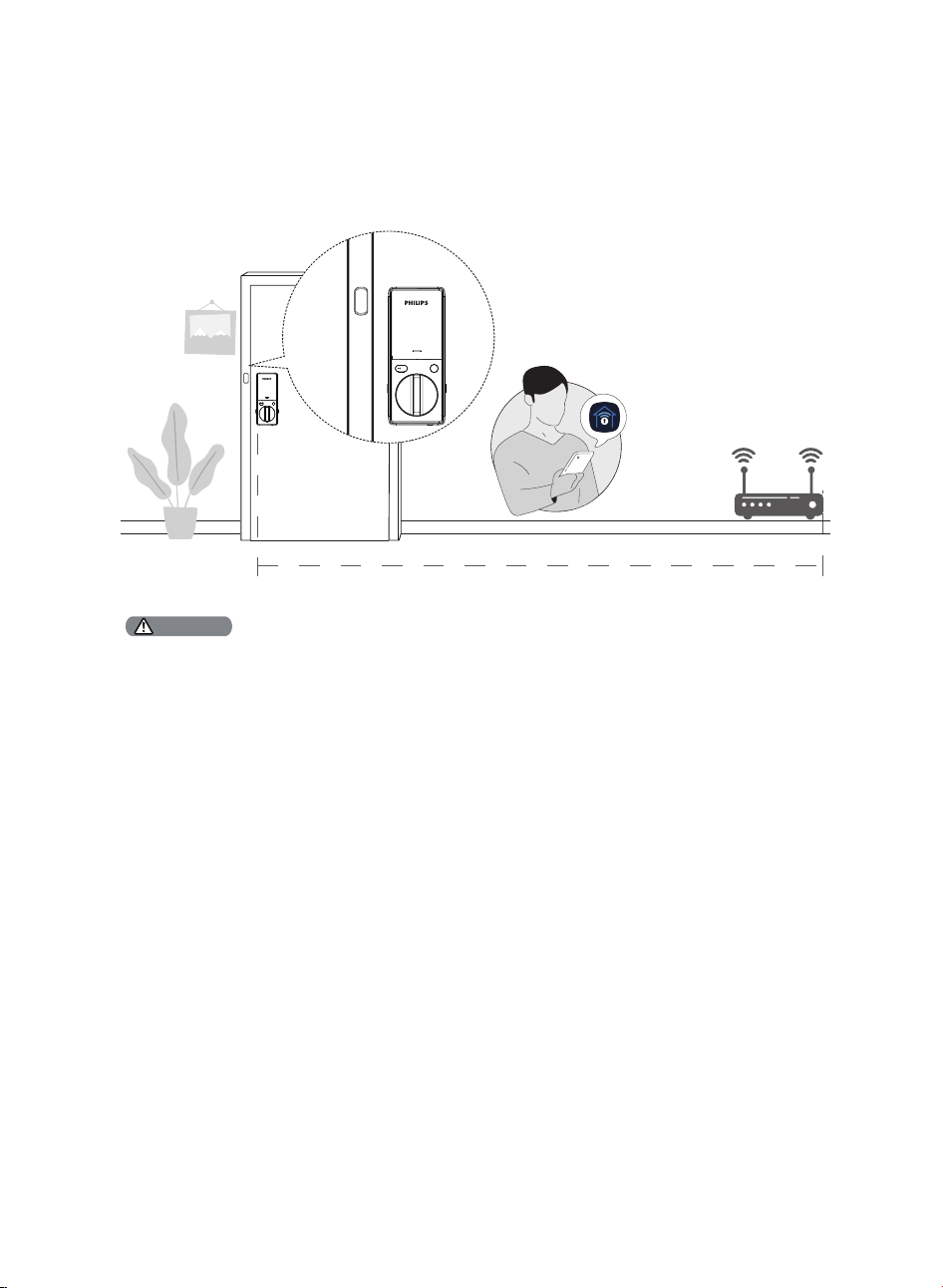
Connect to Your Home Wi-Fi Network
Follow the instructions to connect the lock to the Wi-Fi network.
26 feet (8 meters)
The lock is only compatible with the 2.4 GHz Wi-Fi network. Make sure your phone is connected to the same 2.4 GHz
Wi-Fi before operating.
For optimum connectivity, it is recommended that the home router be no further away from the lock than 26 feet (8
meters).
During the connect process position yourself between the lock and the Wi-Fi Router.
Attention
INDOOR
Home
Access
Wi-Fi 2.4GHz
14

4 How to Use
Feature De�nitions
The Master PIN Code can be used to unlock the deadbolt in Away Mode and Privacy Mode. The
default Master PIN Code (12345678) must be changed before setting up. The owner/manager
should keep this information con�dential.
Master PIN code
Unlock with your Plam(s), PIN Codes, Backup Keys, or a gentle touch on the Philips Home Access
app. The Palm IDs and PIN Codes can be managed on the Phillips Home Access app.
Multiple Ways to Unlock
Tap "Share device" on the Phillips Home Access app to share access with your family or friends.
The access can only be shared and accepted via the Phillips Home Access app.
Simple Sharing
Offers a detailed record of all lock interactions and activities like lock/unlock history and user access.
Real-time noti�cations will be sent to your phone when your smart lock is connected to the home
Wi-Fi network.
Lock Activity
Lock the door by simply pressing and holding any key on the touchscreen for 2s.
One-Touch Locking
Generate PIN codes remotely for guests or a service technician through the Philips Home Access
app. It can be a One-Time PIN Code that will be deleted upon use or a duration PIN code that will
work repeatedly during a speci�c period of time.
Temporary PIN Codes
The unit will automatically lock after it has been unlocked when this setting is on. This feature is
disabled by default. The time delay can be programmed between 30 and 180 seconds in the
Philips Home Access app. The auto lock can also be set in the Philips Home Access app after
calibrating the door position sensor for an immediate auto-lock when the door is closed.
Auto-Lock
After 10 unsuccessful attempts to unlock by PIN Code and/or Palm ID, the keypad will be
temporarily disabled for 3 minutes.
Wrong Entry Limit
The sounds can be muted when pressing the keypad. However, you will still hear low battery
warnings and system alerts.
Silent Mode
15

Push and hold the Privacy Button on the Interior Assembly for 3 seconds to activate Privacy Mode.
This will restrict all User PIN Codes and Palm IDs. Privacy Mode will be disabled automatically after
unlocking the door with the Thumb Turn or the Master PIN Code.
Privacy Mode
The deadbolt will automatically unlock as you approach and grab the door knob or lever indoors.
This feature is disabled by default.
Enable it by setting it on the Philips Home Access app.
Grab and Go
This is a safety feature when you leave your house for a vacation or long trip. Away Mode restricts
all User PIN Codes and Palm ID until the Master PIN Code is entered on the touchscreen keypad.
When the lock is unlocked by the Thumb Turn, an alarm will sound for 1 minute. It will also send a
noti�cation via the Philips Home Access app.
Enable it by setting it on the Philips Home Access app.
By entering the Master PIN Code on the keypad or setting it on the Philips Home Access app, you
can disable the alarm and the Away Mode.
Away Mode
When the batteries are running low, the battery indicator will �ash and a voice will announce
“Low battery. Please replace batteries as soon as possible”. It will also send a noti�cation via the
Philips Home Access app.
Replace the low batteries with 4 new CR123A Lithium Batteries.
Low Battery Alarm
16
Limited lifetime for mechanical and 2 years for electronical warranty
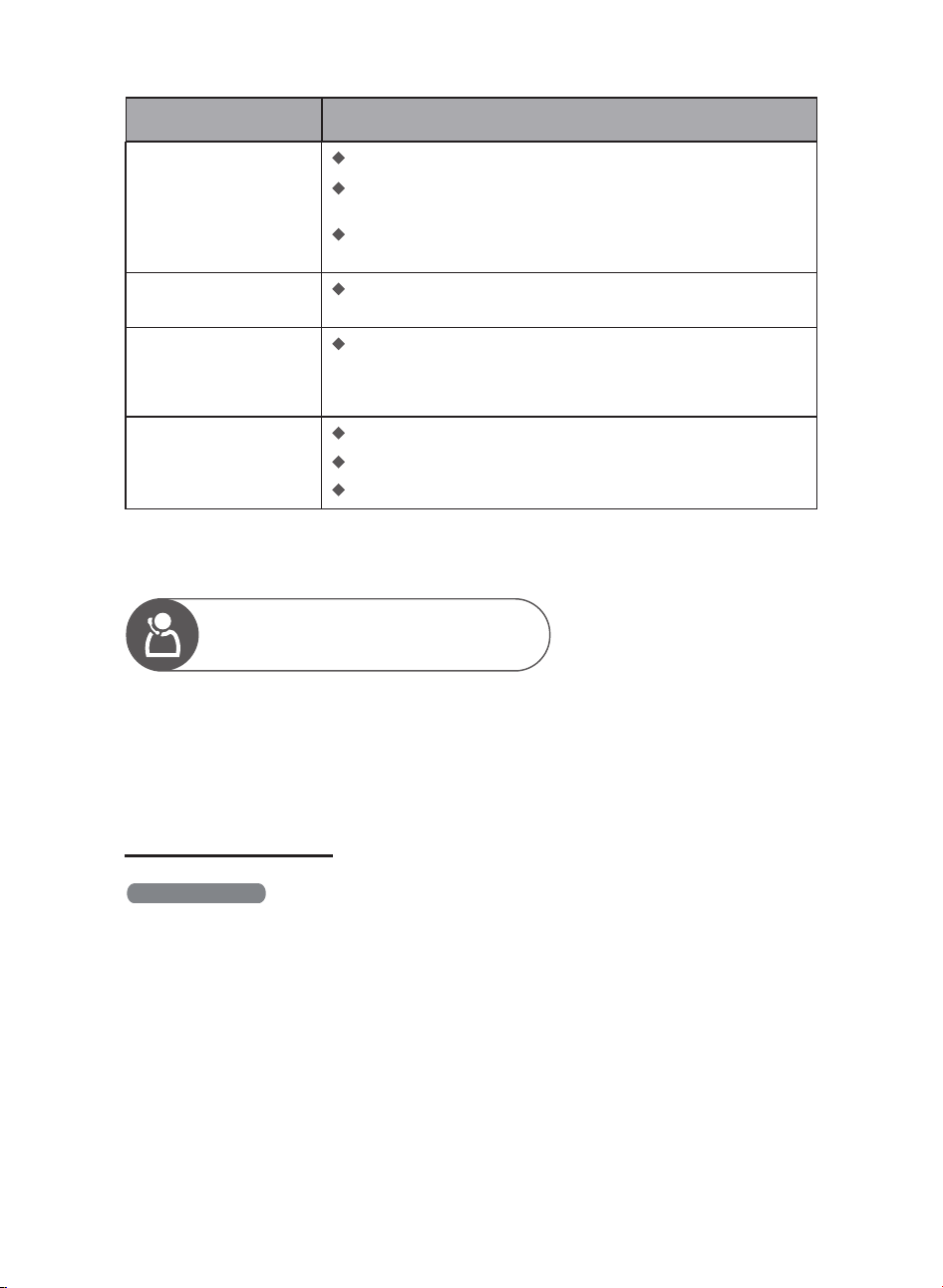
This procedure erases all user and network settings
and unpairs the lock from users' accounts.
All paired accessories will also be removed. Restoring
the lock will also activate the lock-handing process.
Press the Reset Button for at least 5 seconds until you
hear the tone prompting you to restore the default
settings.
Function
Master PIN Code
Auto-Lock
Silent Mode
Shut Down Time
Away Mode
Default Setting
12345678
Disabled
Disabled
3 minutes
Disabled
Factory Reset & Default Settings
1. Master PIN Code (4 to 10 digits): The default Master PIN Code is 12345678. Change the default Master
PIN Code before setting other codes.
2. User PIN Code (4 to 10 digits): A total of 100 User PIN Codes can be set and stored in the lock.
3. Palm ID: 50 Palm IDs can be set and stored in the lock.
4. Both Master and User PIN Codes do not support the following combination of numbers:
12345678
87654321
22222222
5683
568391
915683
If
then
and
A.
A. Forward number
B. Backward number
C. Repeated number
D. Contain existing code
B.
C.
D.
Format of Entry Methods
Calibrate the Door Position Sensor
Follow the instructions in the app until you have successfully calibrated your smart lock and the Door
Position Sensor together.
17
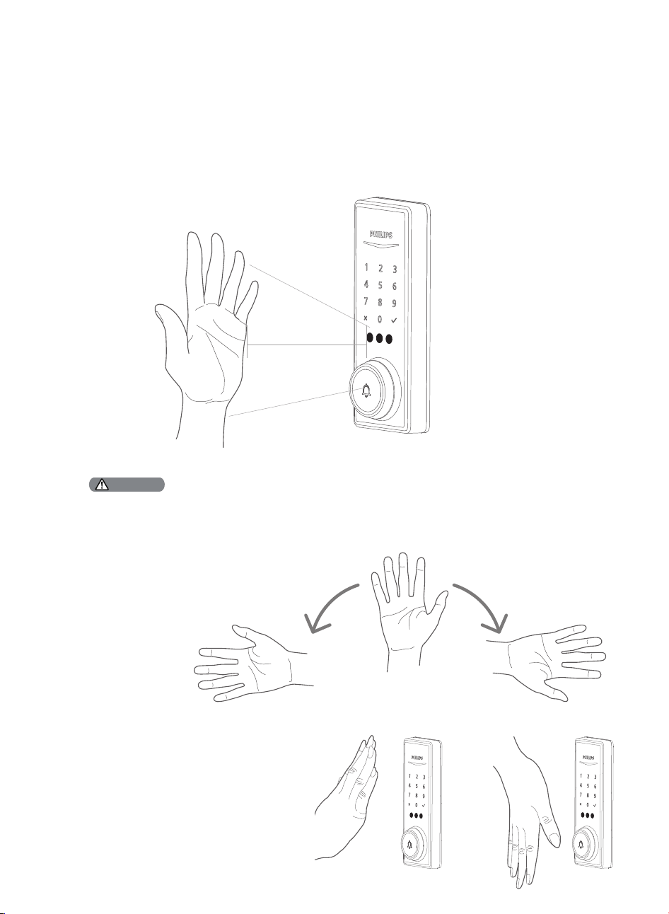
Add a Palm ID
1. Click the "Add Palm ID" button in the Philips Home Access app.
2. Follow the in-app instructions and place your palm in front of the Palm ID Reader. Keep your palm still
while the Palm ID Reader is scanning your palm. The Palm ID Reader will scan your palm vein patterns to
create your unique Palm ID. All of the Palm IDs are securely stored locally.
3. Name the new Palm ID in the app.
After adding a Palm ID, the Palm ID
reader can recognize any palm
direction within a 180-degree range
centered on the palm.
It is recommended to add two Palm IDs for
each palm. Place your palm upward to
add the �rst Palm ID, and place the same
palm downward to add the second Palm
ID. This way, you will be able to unlock the
lock regardless of the position of your
palm.
2" - 6"
(50 - 150mm)
Ensure your palm is about 2"-6" (50-150mm) from the Palm ID Reader.
Ensure that nothing covers the Palm ID Reader or your palm.
Hold your hand still during the Palm ID enrollment process.
Attention
18
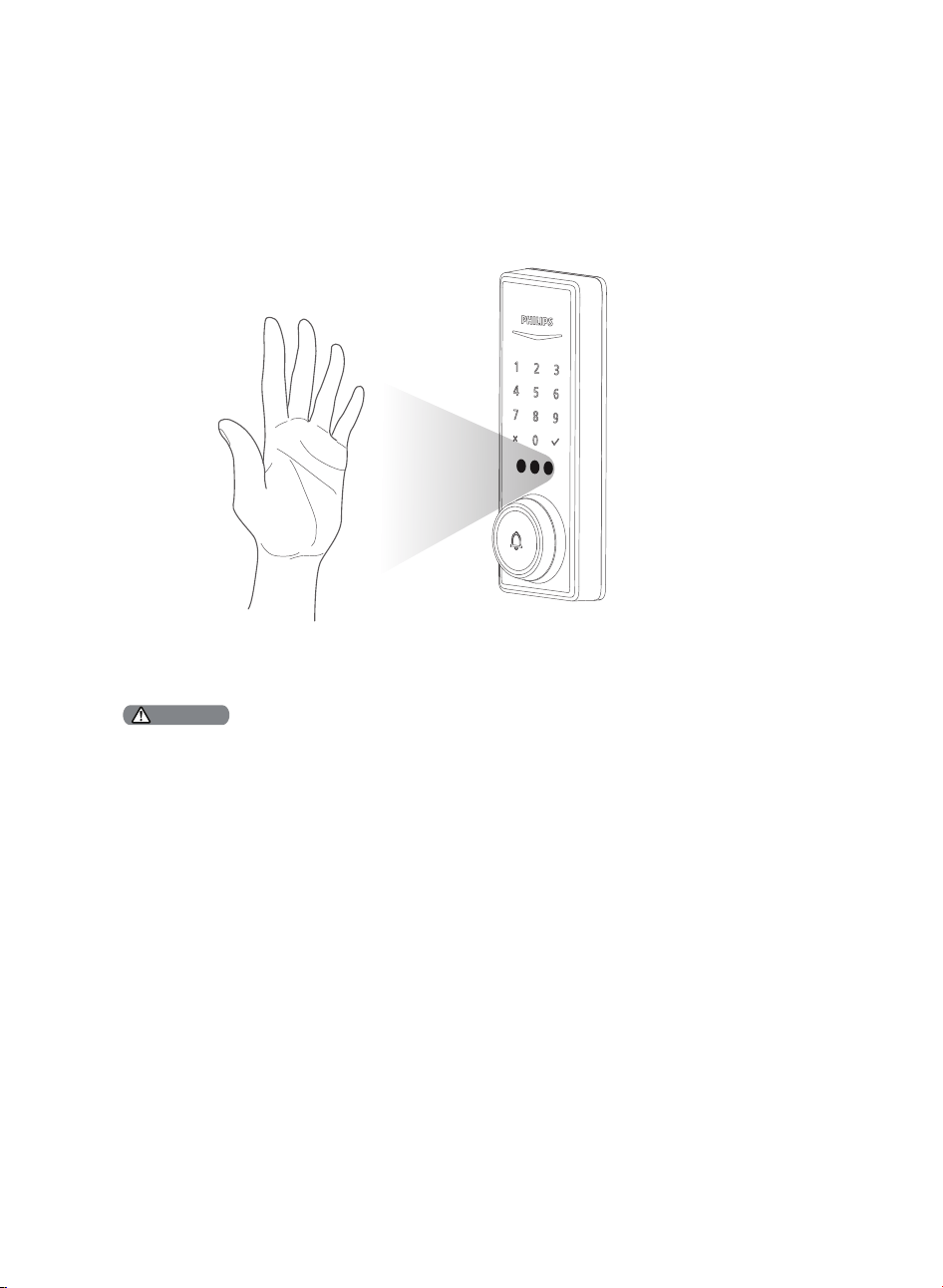
Ensure your palm is about 2"-6" (50-150mm) from the Palm ID Reader.
While verifying your Palm ID, keep your palm in front of the Palm ID Reader area until both the Palm ID Reader and
Touchscreen Keypad lights go out.
Ensure to hold your hand still when unlocking with Palm ID.
Attention
Unlock with Palm ID
The Palm ID reader will automatically wake up once you approach the lock. Place your palm in front of the
Reader to verify your Palm ID and unlock the door.
19
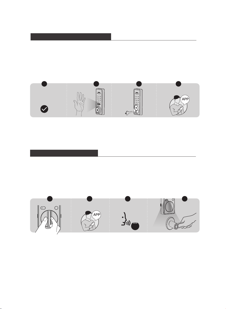
1. Rotate the Thumb Turn to the unlocked position.
2. Unlock by the Philips Home Access app.
3. Unlock by Voice Assistant.
4. Grab and go. (Disabled by default)
Unlocking the Door from Inside
Lock & Unlock
Unlocking the Door from Outside
1. Unlock by PIN Codes.
2. Unlock with Palm ID.
3. Unlock by Backup Key.
4. Unlock by the Philips Home Access app.
1 2 3 4
Home Access app
Voice Assistant
PIN Code
+
1 4
Home Access app
32
20
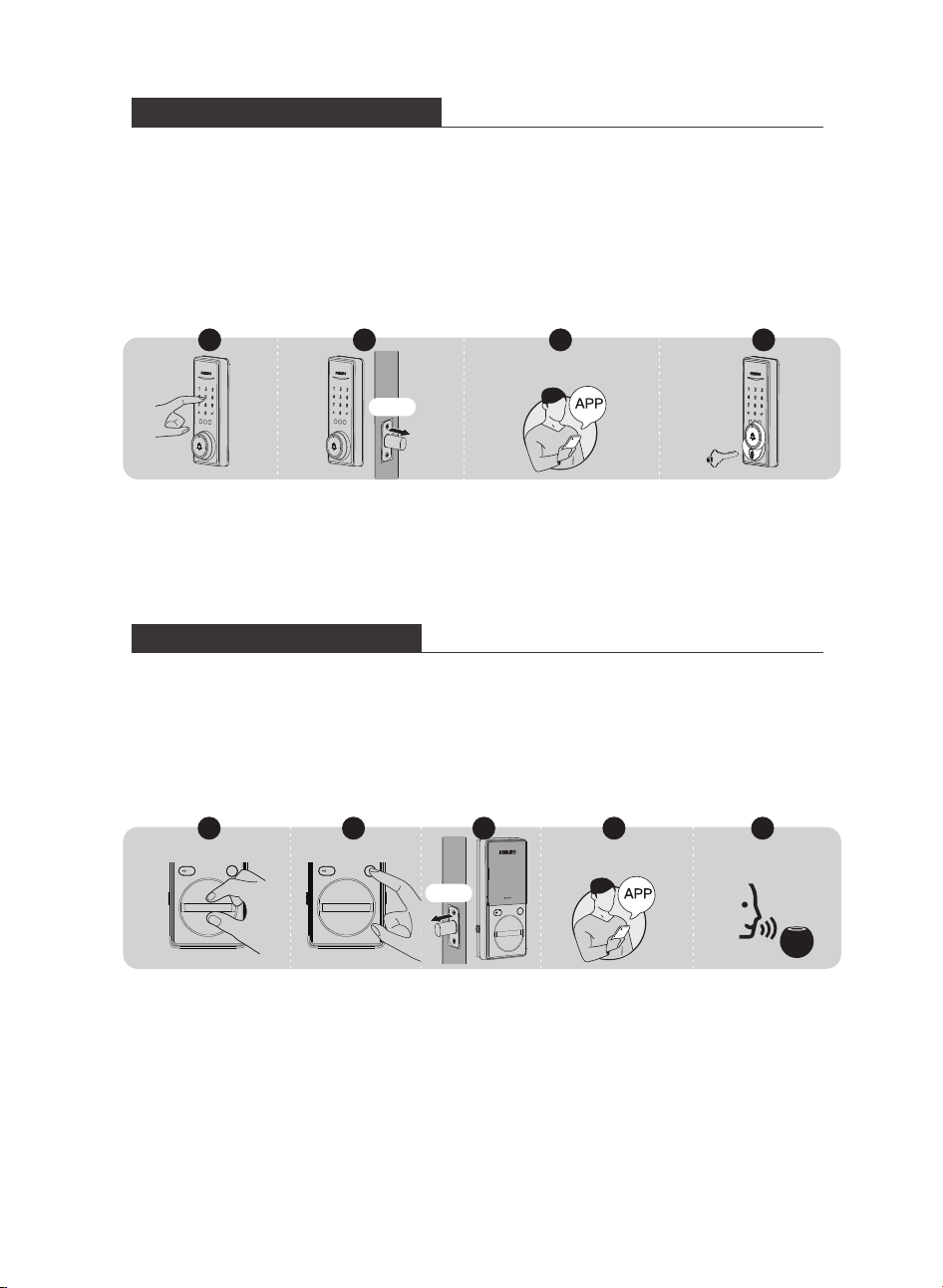
1. Press and hold any key on the touchscreen keypad for at least 2 seconds to lock the device in
Manual Mode.
2. In Auto-Lock mode, the Latch Bolt will automatically extend after it is unlocked and the door is
shut.
3. Lock by the Philips Home Access app.
4. Lock by the Backup Key.
Locking the Door from Outside
3
Home Access app
1. Rotate the Thumb Turn to the locked position to lock the device in Manual Mode.
2. Press the Privacy Button to lock the device in Manual Mode.
3. In Auto-Lock Mode, the device is locked automatically.
4. Lock by the Philips Home Access app.
5. Lock by Voice Assistant.
Locking the Door from Inside
1 2 4 5
Home Access app
Voice Assistant
Auto
2
Auto
1 4
3
21
Limited lifetime for mechanical and 2 years for electronical warranty
Operations & Features
Single-click the Volume Button
Press & hold the Volume Button
Melody Button
Change the volume level
Press and hold for 5 seconds
to enter Pairing Mode
Click the arrows to scroll up or
down to select the melody
you like
5 levels of volume
adjustable: 40dB, 50dB,
60dB, 65dB, 75dB loud.
The Indicator will �ash while
in Pairing mode.
The Indicator will be illuminated
while in Pairing mode.
Contains 38 melodies, and
automatically saves
the set melody after
powering off.
5 Add the Chime
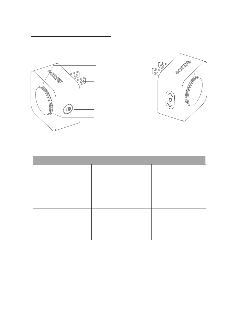
Product Overview
Setup Indicator
Power Plug
Speaker
Volume Button
Philips Chime can be powered
by plugging it into an outlet
that supports 90 to 240V AC.
Melody Button
22
Settings
Accessory
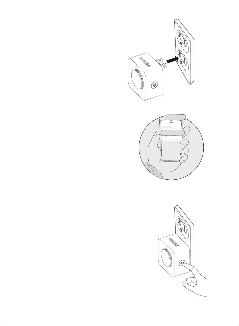
Add the Chime
1. Plug the Chime into any standard power outlet.
(Suggestion: Plug the Chime into the outlet near the
lock, and transfer it to another room after adding it).
After the Chime is successfully paired, it can be
moved to other rooms.
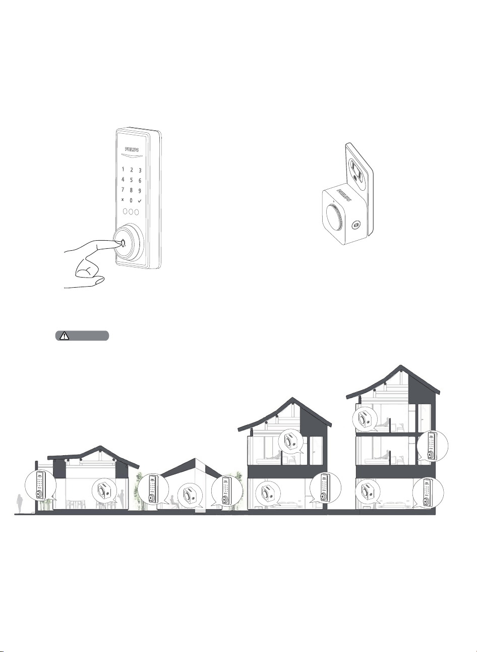
The maximum distance between the Chime and the
smart lock is 328 feet (100m)in an open space.
It is recommended that there be no more than three
walls between the Chime and the lock.
2. Open the Philips Home Access app and select the
lock you want to add the Chime to and �nd the ″Add
accessories″ option.
3. Press and hold the Chime's Setup Button for 3
seconds to enter Pairing Mode.
You will see the Chime's Indicator Light �ash 1 time,
and then the light will remain on. At the same time,
you can hear a “Ding Dong” sound, indicating it is
ready to pair with the lock.
Pairing the Chime will last for 1 minute.
23
4. Follow the in-app instructions to complete the pairing.
When the Chime's Indicator Light �ashes 1 time and rings again, that means they have connected and are
able to function together.
5. After adding the Chime, try the doorbell on the lock and check whether the Chime works appropriately.
A Philips smart deadbolt can be connected to multiple Chimes, and a Chime can be added with multiple Philips smart
deadbolts.
Attention
24
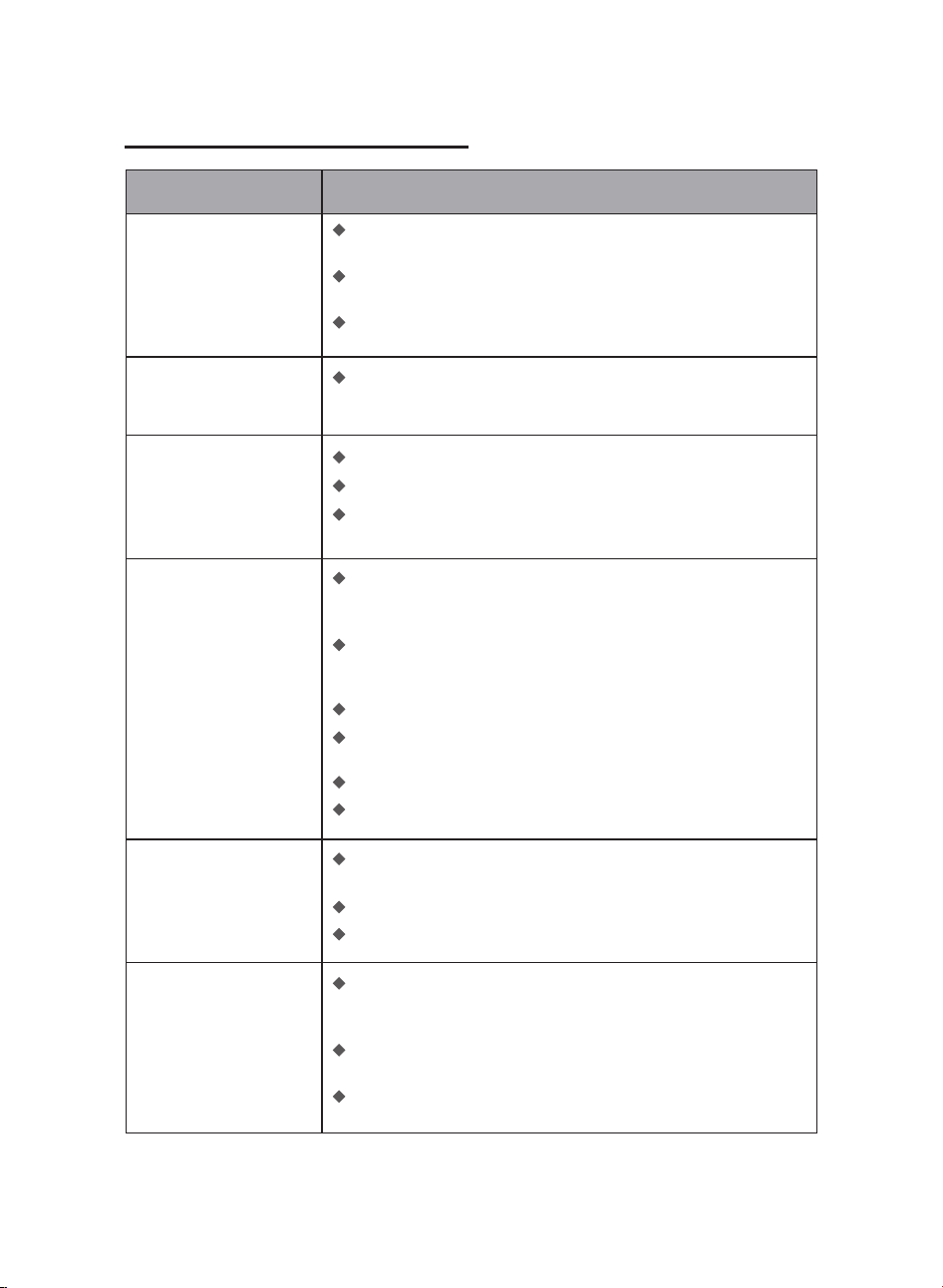
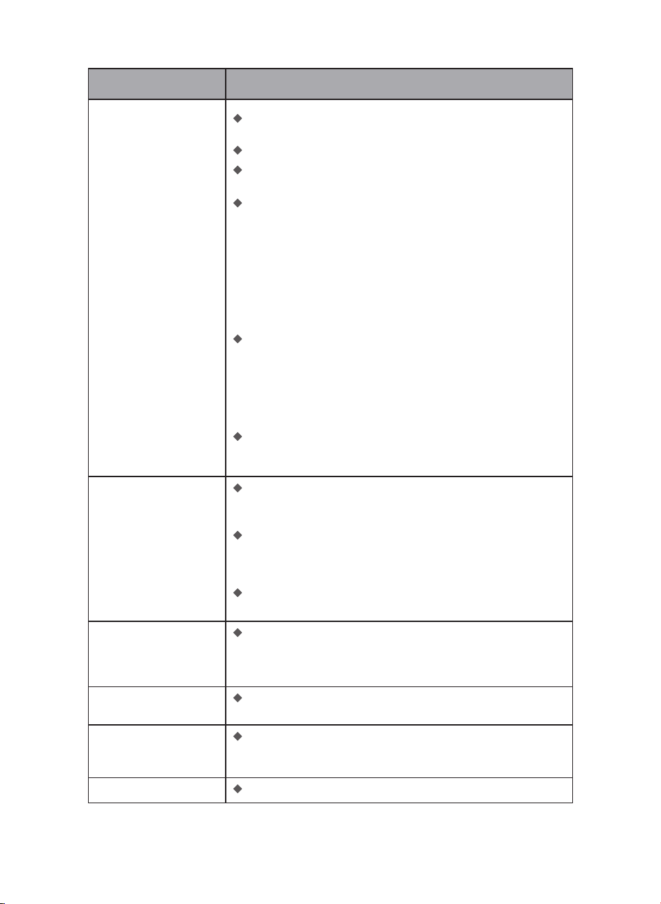
6 Troubleshooting
Issue Solution
The Latch Bolt does
not operate correctly
after installation.
The lock does not smoothly
lock or unlock while using
the Thumb Turn.
Make sure the backset on the Latch Bolt is set to the proper
length. Refer to page 8.
Make sure the latch bolt is retracted before installation. Refer to
page 9.
Restore the lock to the default settings. Enter the default Master
PIN Code to set up the lock.
Con�rm the Mounting Screws are properly installed.
Failed to Scan the QR
Code on the device.
Scan the QR Code in a well-lit environment, use the built-in
�ashlight on your phone, or try to scan in an environment with
sufficient lighting.
Ensure enough distance between your smartphone and the QR
Code, and ensure the QR Code is at the center of your phone screen.
Direct lighting or sunlight can cause re�ections that will interfere
with the scanning process.
Failed to set up the lock
in the app.
Make sure the lock is installed correctly.
Insert fresh batteries and make sure that the cable is not pinched.
After installation, reset the lock to factory settings to complete the
lock setting process.
Failed to add the device
via Bluetooth.
Make sure your smart lock has enough power, and your phone is
close to it.
Check your phone's Bluetooth settings and ensure it's turned on.
If you have an Android device, enable the Location Service.
Failed to connect to
Wi-Fi.
An unstable Wi-Fi signal affects the connection between the
device and your Wi-Fi router. It would be best if you strengthen
the Wi-Fi signal to the device to ensure it operates properly.
Check your available networks. Make sure your lock is connected
to a 2.4GHz Wi-Fi network or “dual-band” Wi-Fi, which supports
both 2.4GHz and 5GHz frequency bands.
Check to make sure you have entered the correct Wi-Fi password.
Ensure your Wi-Fi password is less than 26 characters and does not
contain Spaces.
Try performing the setup on a different mobile device.
Perform a factory reset to repeat the setup process.
25
Issue Solution
The device is showing
offline.
Ensure your lock has enough power. If the batteries run low,
please remove the batteries and insert 4 new CR123A Lithium
Batteries.
Please verify if your router has Internet access. If the home
network experiences an outage or a network connectivity issue,
the lock is expected to restore its Wi-Fi connection when the
home network recovers.
If the home network is back online and the lock has not restored
its Wi-Fi connection, you may try resetting your lock.
I cannot unlock the
device with my palm
ID.
Ensure that nothing is covering the Palm ID Reader and your palm
is not obscured.
Ensure that the palm being used has been added successfully.
Ensure your palm is about 2"-6" (50-150mm) from the Palm ID
Reader. Hold your hand still when unlocking with Palm ID.
Delete and re-add this Palm ID to the Philips Home Access app.
Make sure the palm is not obscured and centered in front of the
Palm ID reader when adding it.
When adding your Palm ID, hold your hand still during the Palm
ID enrollment process.
If you only add a Palm ID in an upward direction of your palm,
�ipping the palm may cause an unlocking failure. Make sure
your palm is facing the same direction as when you added it - see
page 18.
After adding a Palm ID, the Palm ID reader can recognize any
direction your palm is turned within a 180-degree range centered
on the palm. It is recommended to add two Palm IDs for each
palm. Place your palm upward to add the �rst Palm ID, and place
the same palm downward to add the second Palm ID. This way,
you will be able to unlock the lock regardless of the position of
your palm. See page 18 for more details.
Ensure your lock has enough power. If the batteries are running
low, unlock the device with a key, remove the batteries, and insert
4 new CR123A Lithium Batteries.
The app displays that
the door is open when
the door is closed.
Metal objects and magnetic �eld changes near the door lock can
affect the accuracy of the Door Sensor. To �x this, remove any
potential sources of interference and recalibrate the Door Sensor
within the app.
The lock rotates only if
the Key is Inserted.
Make sure the Latch Bolt is installed correctly. Refer to page 9.
The door handing is
not activated after the
battery is installed.
Press the Reset Button for at least 5 seconds until you hear the
tone prompting you to restore the default settings.
Receiving low battery alert.
Remove the batteries and insert 4 new CR123A Lithium Batteries.
26
7 Warranty
For more information on the warranty applicable for this product, please visit www.philips.com or
contact the dealer where you purchased the product.
2 Years Warranty
The keypad is not
responding.
Make sure batteries are inserted correctly.
If the battery indicator �ashes continuously, the batteries are low.
Please replace them with 4 new CR123A Lithium Batteries.
Make sure that the cable is properly connected and has not been
damaged during installation.
The Master PIN Code
cannot be changed.
Restore factory settings and reprogram all user PIN codes.
Still have questions or need help? Please feel free to contact us:
U.S.A. & Canada: +1(833)599-9111
Issue Solution
I forgot my Master
PIN Code.
Perform a factory reset to clear all PIN Codes and Palm IDs. Once
the reset is completed, all PIN codes will be deleted and the
Master PIN Code will be reset to the default Master PIN Code of
12345678.
Auto-Lock is not
working.
If the battery indicator �ashes continuously, the batteries are low.
Please replace them with 4 new CR123A Lithium Batteries.
Activate the Auto-Lock function.
27

8 FCC Statement
This equipment has been tested and found to comply with the limits for a Class B digital device,
pursuant to part 15 of the FCC Rules. These limits are designed to provide reasonable protection
against harmful interference in a residential installation. This equipment generates, uses and can
radiate radio frequency energy and, if not installed and used in accordance with the instructions, may
cause harmful interference to radio communications. However, there is no guarantee that interference
will not occur in a particular installation. If this equipment does cause harmful interference to radio or
television reception, which can be determined by turning the equipment off and on, the user is
encouraged to try to correct the interference by one or more of the following measures:
• Reorient or relocate the receiving antenna.
• Increase the separation between the equipment and receiver.
• Connect the equipment into an outlet on a circuit different from that to which the receiver is
connected.
• Consult the dealer or an experienced radio/TV technician for help.
Caution: Any changes or modifications to this device not explicitly approved by manufacturer could
void your authority to operate this equipment.
This device complies with part 15 of the FCC Rules. Operation is subject to the following two
conditions: (1) This device may not cause harmful interference, and (2) this device must accept any
interference received, including interference that may cause undesired operation.
RF Exposure Information
This equipment complies with FCC radiation exposure limits set forth for an uncontrolled environment.
This equipment should be installed and operated with minimum distance 20cm between the radiator
and your body.
28

English: This device contains licence-exempt transmitter(s)/receiver(s) that comply with Innovation,
Science and Economic Development Canada’s licence-exempt RSS(s). Operation is subject to the following
two conditions:
(1) This device may not cause interference.
(2) This device must accept any interference, including interference that may cause undesired operation
of the device.
The digital apparatus complies with Canadian CAN ICES‐3 (B)/NMB‐3(B).
French: Cet appareil contient des émetteurs/récepteurs exempts de licence qui sont conformes aux RSS
exemptés de licence d'Innovation, Sciences et Développement économique Canada.
L'exploitation est soumise aux deux conditions suivantes :
(1) Cet appareil ne doit pas provoquer d'interférences.
(2) Cet appareil doit accepter toute interférence, y compris les interférences susceptibles de provoquer un
fonctionnement indésirable de l'appareil.
l'appareil numérique du ciem conforme canadien peut‐3 (b) / nmb‐3 (b).
This device meets the exemption from the routine evaluation limits in section 2.5 of RSS 102 and
compliance with RSS 102 RF exposure, users can obtain Canadian information on RF exposure and
compliance.
cet appareil est conforme à l'exemption des limites d'évaluation courante dans la section 2.5 du cnr - 102
et conformité avec rss 102 de l'exposition aux rf, les utilisateurs peuvent obtenir des données
canadiennes sur l'exposition aux champs rf et la conformité.
This equipment complies with Canada radiation exposure limits set forth for an uncontrolled environ-
ment.
Cet équipement est conforme aux limites d'exposition aux rayonnements du Canada établies pour un
environnement non contrôlé.
This equipment should be installed and operated with minimum distance 20cm between the radiator &
your body.
Cet équipement doit être installé et utilisé à une distance minimale de 20 cm entre le radiateur et votre
corps.
9 ISED Statement
29

Philips and the Philips Shield Emblem are registered trademarks of Koninklijke
Philips N.V. and are used under license. This product has been manufactured by
and is sold under the responsibility of Shenzhen Conex Intelligent Technology
Co., Ltd. and Shenzhen Conex Intelligent Technology Co., Ltd. is the warrantor
concerning this product.
DDL250X-14HWC V1.0