user manual
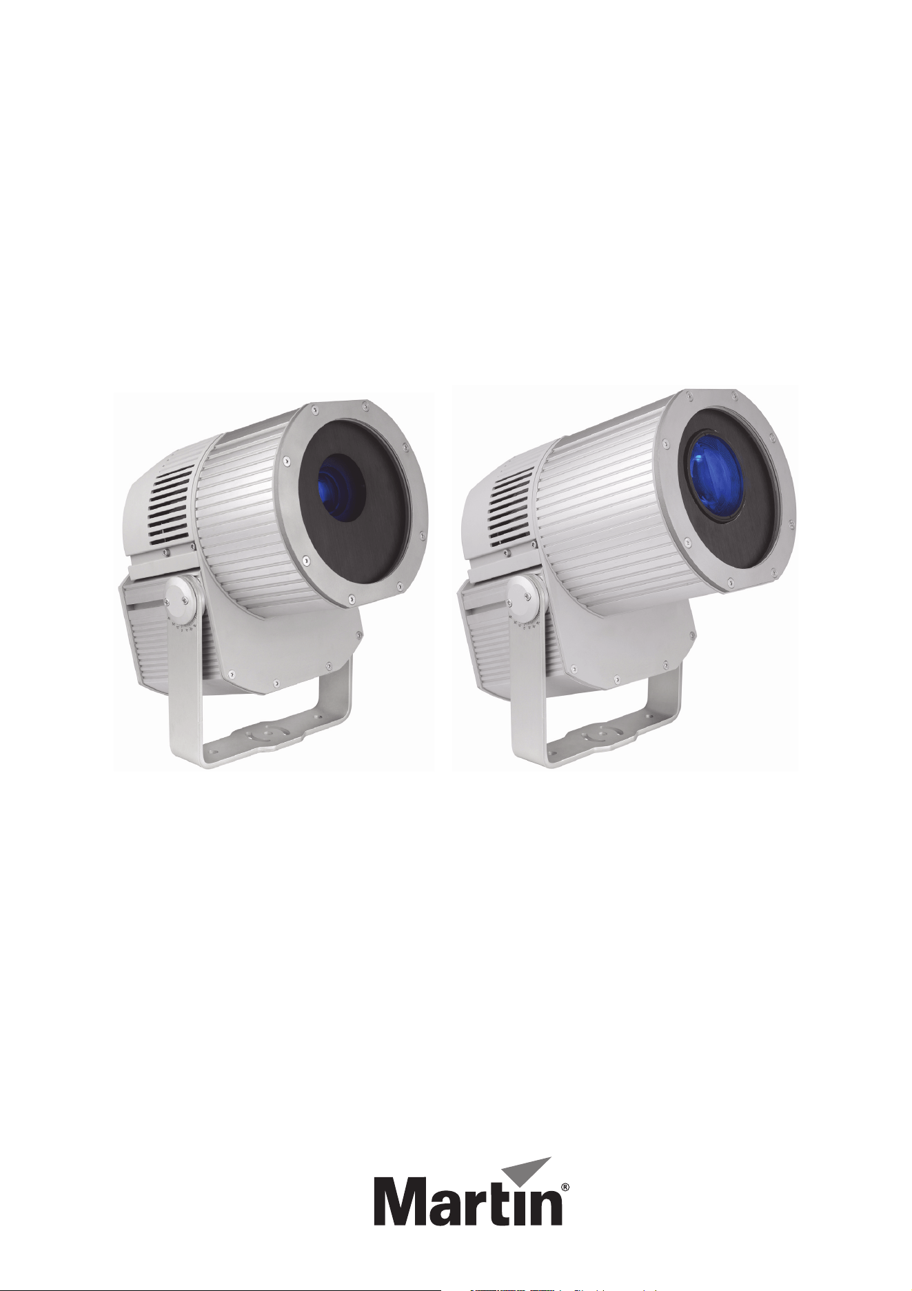
Exterior 400
Image Projector™
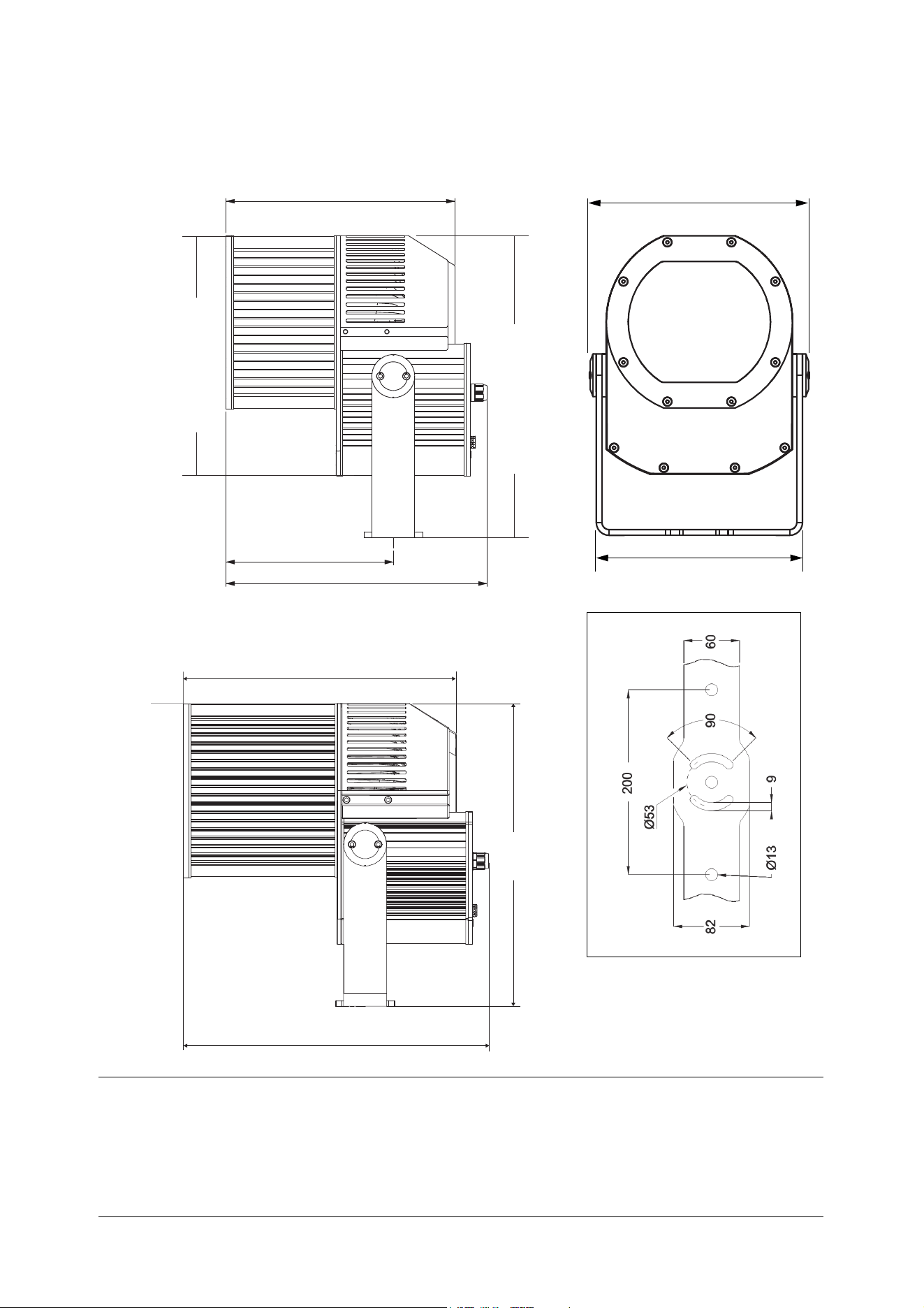
Dimensions
All dimensions are in millimeters
234
365
320
335
421
307
290
380
425
421
Narrow-angle models (long barrel)
©2011-2012 Martin Professional A/S. Information subject to change without notice. Martin Professional A/S and all affiliated
companies disclaim liability for any injury, damage, direct or indirect loss, consequential or economic loss or any other loss
occasioned by the use of, inability to use or reliance on the information contained in this manual. The Martin logo, the Martin name
and all other trademarks in this document pertaining to services or products by Martin Professional A/S or its affiliates and
subsidiaries are trademarks owned or licensed by Martin Professional A/S or its affiliates or subsidiaries. The use of certain patents
in Martin Exterior 400 Image Projector products is licensed by Color Kinetics, Inc. (see details printed on product).
P/N 35000256, Rev. E
Safety Information
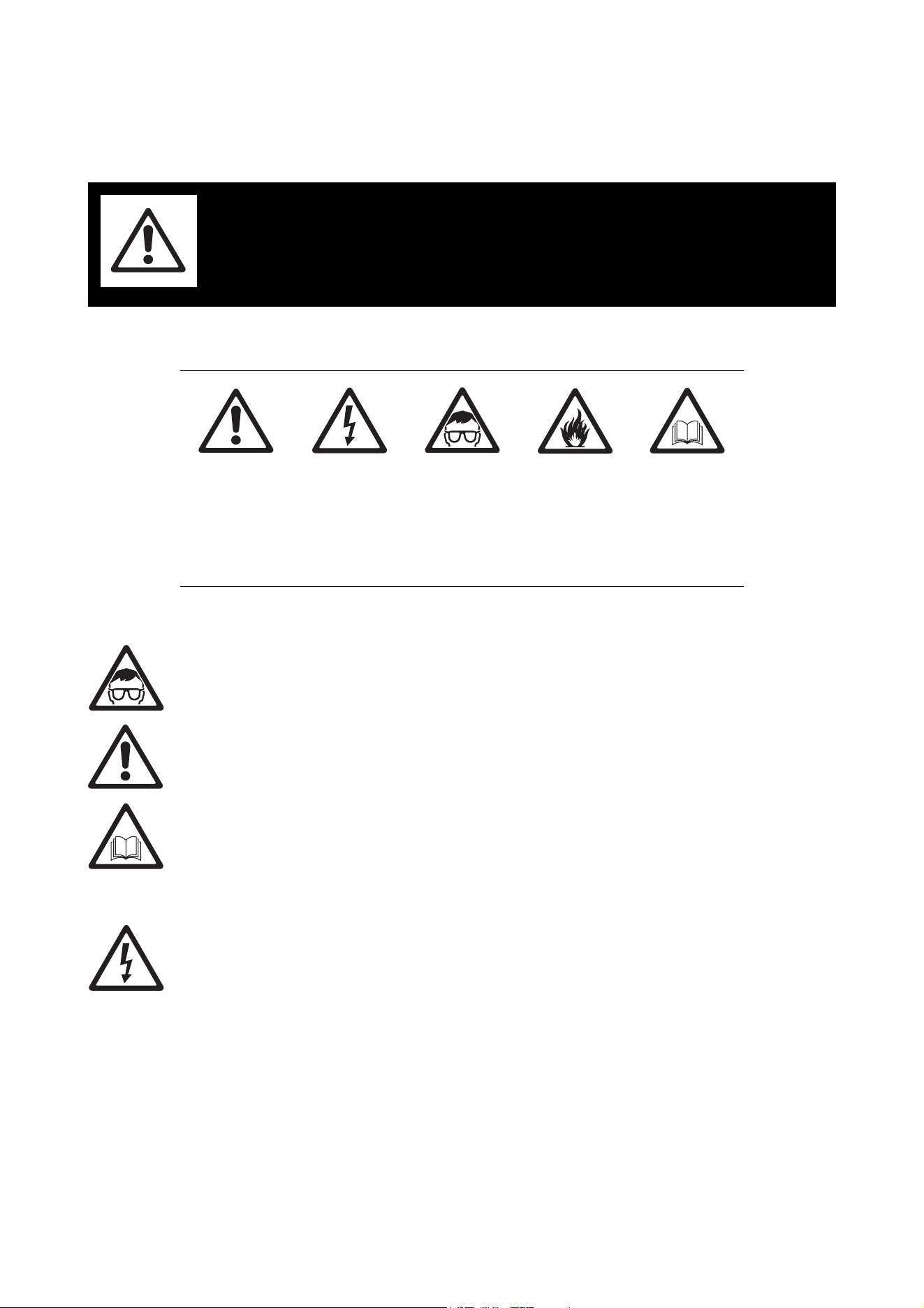
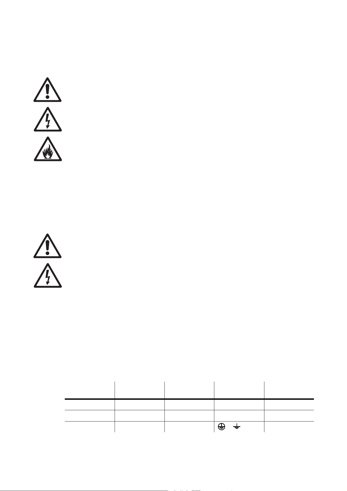
The following symbols are used to identify important safety information on the product and in this manual:
WARNING! Risk Group 2 LED product according to EN 62471. Do not look into the beam at a
distance of less than 8.3 m (27.3 ft.) from the front surface of the product. Do not view the light
output with optical instruments or any device that may concentrate the beam.
This product is for professional use only. It is not for household use.
This product presents risks of severe injury or death due to fire hazards, electric shock and falls.
Read this manual before installing, powering or servicing the fixture, follow the safety precautions listed
below and observe all warnings in this manual and printed on the fixture. Install and operate the fixture only
as described in this manual and in accordance with local laws and regulations. Refer any operation not
described in this manual to an authorized Martin Service partner.
Terminal block not included.
Installation may require advice from a qualified person.
If you have any questions about how to install or operate the fixture safely, please contact your Martin
supplier or call the Martin 24-hour service hotline on +45 8740 0000, or in the USA on 1-888-tech-180.
PROTECTION FROM ELECTRIC SHOCK
• Shut down power to the entire installation at the main power distribution board and ensure that it cannot
be reapplied, deliberately or accidentally, before carrying out any installation or maintenance work.
• Disconnect the fixture from AC power before removing or installing any cover or part and when not in use.
• Connect the fixture electrically to ground (earth).
• Use only a source of AC power that complies with local building and electrical codes and has both
overload and ground-fault (earth-fault) protection.
• Connect the fixture to AC power using the supplied power cable only. The power and data cables supplied
with the fixture may only be replaced by Martin Professional or its authorized agents. If either of the
supplied cables is in any way unsuitable, contact Martin Professional for assistance.
• Before using the fixture, check that all power distribution equipment and cables are in perfect condition,
are rated for the current requirements of all connected devices, are protected to IP67 or higher and are of
suitable type for the location (including water, pollution, temperature and UV resistance).
• Isolate the fixture from power immediately if any cable, seal, cover or other component is damaged,
cracked, deformed or shows signs of overheating. Contact Martin Professional for assistance and do not
reapply power until repairs have been completed.
WARNING!
Read the safety precautions in this section before
installing, powering, operating or servicing this
product.
WARNING!
Safety hazard.
Risk of severe
injury or death.
WARNING!
Hazardous
voltage. Risk of
lethal or severe
electric shock.
WARNING!
LED light
emission. Risk
Group 2 LED
product
according to EN
62471.
WARNING!
Fire hazard.
WARNING!
Refer to user
manual.
• Do not expose any part of the fixture to a high-pressure water jet.
• Do not immerse the fixture in water or any other fluid, or install it in a location where flooding may occur.
• Refer any service operation not described in this manual to an authorized Martin Service partner.
PROTECTION FROM BURNS AND FIRE
• Do not operate the fixture if the ambient temperature (Ta) exceeds 45° C (113° F).
• The exterior of the fixture becomes hot, up to 65° C (149° F) during normal operation. Ensure that
accidental physical contact with a hot fixture is impossible.
• Allow the fixture to cool for at least 30 minutes before servicing.
• Do not illuminate any surface that is less than 0.5 m (20 ins.) from the front of the fixture.
• Keep flammable materials well away from the fixture.
• Do not modify the fixture in any way not described in this manual or install other than genuine Martin
parts. Do not stick filters, masks or other materials directly onto LEDs or the front glass. Use only
Martin-approved accessories to mask or modify the light beam.
• Install the fixture outdoors or in a well-ventilated area only. Provide unrestricted airflow and a minimum
clearance of 0.1 m (4 ins.) around the fixture.
PROTECTION FROM INJURY
• Classified as LED Risk Group 2 product with all LEDs at full intensity according to IEC 62471. Do not look
at LEDs from a distance of less than 8.3 m (27.3 ft.) from the front surface of the fixture without suitable
protective eyewear. At less than this distance, the LED emission can cause eye injury or irritation. At
distances of 8.3 m (27.3 ft.) and above, light output is harmless to the naked eye provided that the eye’s
natural aversion response is not overcome.
• Do not look at LEDs with magnifiers or similar optical instruments that may concentrate the light output.
• Ensure that persons are not looking at the LEDs from within 8.3 m (27.3 ft.) when the product lights up
suddenly. This can happen when power is applied, when the product receives a DMX signal or when
stand-alone operation starts.
• Ensure that all external covers, components and installation fittings are securely fastened.
• Block access below the work area and work from a stable platform whenever installing, servicing or
moving the fixture.
• Ensure that all supporting structures, surfaces, fasteners and lifting equipment can bear the weight of all
the devices they are intended to support plus an adequate safety margin, and that they conform to local
building and safety regulations.
• Use a sufficient number of fasteners with sufficient corrosion resistance, dimensions and strength to
mount the fixture safely. Any nuts used must be self-locking. Washers must be installed directly under the
fasteners’ heads when anchoring the yoke base to the installation surface.
• If the fixture is installed in a location where it may cause injury or damage if it falls, install as described in
this manual a secondary attachment such as a safety cable that is approved by an official body such as
TÜV as a safety attachment for the weight that it secures. The safety cable must comply with EN
60598-2-17 Section 17.6.6 and be capable of bearing a static suspended load that is ten times the weight
of the fixture and all installed accessories.
Disposing of this product
Martin™ products are supplied in compliance with Directive 2002/96/EC of the European
Parliament and of the Council of the European Union on WEEE (Waste Electrical and Electronic
Equipment), as amended by Directive 2003/108/EC, where applicable.
Help preserve the environment! Ensure that this product is recycled at the end of its life. Your
supplier can give details of local arrangements for the disposal of Martin products.

Contents
Dimensions . . . . . . . . . . . . . . . . . . . . . . . . . . . . . . . . . . . . . . . . . . . . . . . . . . . . . . . . . . . . . . . . . . . . . . . . 2
Safety Information. . . . . . . . . . . . . . . . . . . . . . . . . . . . . . . . . . . . . . . . . . . . . . . . . . . . . . . . . . . . . . . . . . 3
Introduction . . . . . . . . . . . . . . . . . . . . . . . . . . . . . . . . . . . . . . . . . . . . . . . . . . . . . . . . . . . . . . . . . . . . . . . . 6
Unpacking . . . . . . . . . . . . . . . . . . . . . . . . . . . . . . . . . . . . . . . . . . . . . . . . . . . . . . . . . . . . . . . . . . . . . . . . 6
Using for the first time . . . . . . . . . . . . . . . . . . . . . . . . . . . . . . . . . . . . . . . . . . . . . . . . . . . . . . . . . . . . . . . 6
Installing color filters and gobos. . . . . . . . . . . . . . . . . . . . . . . . . . . . . . . . . . . . . . . . . . . . . . . . . . . . . 7
Filter and gobo care. . . . . . . . . . . . . . . . . . . . . . . . . . . . . . . . . . . . . . . . . . . . . . . . . . . . . . . . . . . . . . . . . 7
Access to the effects module. . . . . . . . . . . . . . . . . . . . . . . . . . . . . . . . . . . . . . . . . . . . . . . . . . . . . . . . . . 8
Installing color filters . . . . . . . . . . . . . . . . . . . . . . . . . . . . . . . . . . . . . . . . . . . . . . . . . . . . . . . . . . . . . . . . 9
Installing gobos . . . . . . . . . . . . . . . . . . . . . . . . . . . . . . . . . . . . . . . . . . . . . . . . . . . . . . . . . . . . . . . . . . . 10
Reinstallation after accessing the effects module . . . . . . . . . . . . . . . . . . . . . . . . . . . . . . . . . . . . . . . . . 12
Physical installation . . . . . . . . . . . . . . . . . . . . . . . . . . . . . . . . . . . . . . . . . . . . . . . . . . . . . . . . . . . . . . . 13
Location and orientation . . . . . . . . . . . . . . . . . . . . . . . . . . . . . . . . . . . . . . . . . . . . . . . . . . . . . . . . . . . . 13
Fastening to a surface . . . . . . . . . . . . . . . . . . . . . . . . . . . . . . . . . . . . . . . . . . . . . . . . . . . . . . . . . . . . . . 15
Tilt adjustment . . . . . . . . . . . . . . . . . . . . . . . . . . . . . . . . . . . . . . . . . . . . . . . . . . . . . . . . . . . . . . . . . . . . 15
Power and DMX data cable layout . . . . . . . . . . . . . . . . . . . . . . . . . . . . . . . . . . . . . . . . . . . . . . . . . 16
AC mains power . . . . . . . . . . . . . . . . . . . . . . . . . . . . . . . . . . . . . . . . . . . . . . . . . . . . . . . . . . . . . . . . . . 18
Connecting to power . . . . . . . . . . . . . . . . . . . . . . . . . . . . . . . . . . . . . . . . . . . . . . . . . . . . . . . . . . . . . . . 18
Control data link. . . . . . . . . . . . . . . . . . . . . . . . . . . . . . . . . . . . . . . . . . . . . . . . . . . . . . . . . . . . . . . . . . . 20
Connecting the data link . . . . . . . . . . . . . . . . . . . . . . . . . . . . . . . . . . . . . . . . . . . . . . . . . . . . . . . . . . . . 21
Effects. . . . . . . . . . . . . . . . . . . . . . . . . . . . . . . . . . . . . . . . . . . . . . . . . . . . . . . . . . . . . . . . . . . . . . . . . . . . 22
Fixture setup. . . . . . . . . . . . . . . . . . . . . . . . . . . . . . . . . . . . . . . . . . . . . . . . . . . . . . . . . . . . . . . . . . . . . . 23
Setting up using MUM . . . . . . . . . . . . . . . . . . . . . . . . . . . . . . . . . . . . . . . . . . . . . . . . . . . . . . . . . . . . . . 23
Setting up via RDM . . . . . . . . . . . . . . . . . . . . . . . . . . . . . . . . . . . . . . . . . . . . . . . . . . . . . . . . . . . . . . . . 26
Operation. . . . . . . . . . . . . . . . . . . . . . . . . . . . . . . . . . . . . . . . . . . . . . . . . . . . . . . . . . . . . . . . . . . . . . . . . 27
DMX control. . . . . . . . . . . . . . . . . . . . . . . . . . . . . . . . . . . . . . . . . . . . . . . . . . . . . . . . . . . . . . . . . . . . . . 27
Stand-alone operation . . . . . . . . . . . . . . . . . . . . . . . . . . . . . . . . . . . . . . . . . . . . . . . . . . . . . . . . . . . . . . 27
Service and maintenance. . . . . . . . . . . . . . . . . . . . . . . . . . . . . . . . . . . . . . . . . . . . . . . . . . . . . . . . . . 33
Cleaning. . . . . . . . . . . . . . . . . . . . . . . . . . . . . . . . . . . . . . . . . . . . . . . . . . . . . . . . . . . . . . . . . . . . . . . . . 33
Replacing filters and gobos . . . . . . . . . . . . . . . . . . . . . . . . . . . . . . . . . . . . . . . . . . . . . . . . . . . . . . . . . . 34
Fixture readouts in MUM . . . . . . . . . . . . . . . . . . . . . . . . . . . . . . . . . . . . . . . . . . . . . . . . . . . . . . . . . . . . 34
Software installation. . . . . . . . . . . . . . . . . . . . . . . . . . . . . . . . . . . . . . . . . . . . . . . . . . . . . . . . . . . . . . . . 34
Status indicator LEDs . . . . . . . . . . . . . . . . . . . . . . . . . . . . . . . . . . . . . . . . . . . . . . . . . . . . . . . . . . . . . . 35
Adjustment. . . . . . . . . . . . . . . . . . . . . . . . . . . . . . . . . . . . . . . . . . . . . . . . . . . . . . . . . . . . . . . . . . . . . . . 35
DMX protocol . . . . . . . . . . . . . . . . . . . . . . . . . . . . . . . . . . . . . . . . . . . . . . . . . . . . . . . . . . . . . . . . . . . . . 36
Troubleshooting. . . . . . . . . . . . . . . . . . . . . . . . . . . . . . . . . . . . . . . . . . . . . . . . . . . . . . . . . . . . . . . . . . . 38
Specifications . . . . . . . . . . . . . . . . . . . . . . . . . . . . . . . . . . . . . . . . . . . . . . . . . . . . . . . . . . . . . . . . . . . . . 39

6 Exterior 400 Image Projector user manual
Introduction
Thank you for selecting the Exterior 400™ Image Projector, a compact IP65-rated LED-based
color-changing projector from Martin Professional™. The Exterior 400 Image Projector features:
• Seven Luminus CBT-90 (50 W) LEDs
• Narrow-, medium- and wide-angle options
• Motorized rotating gobo wheel with slots for 6 interchangeable gobos plus open, indexing, continuous
gobo rotation & scrolling, shake
• Motorized color wheel with slots for 8 interchangeable color filters plus open
• Motorized iris
• Electronic shutter with instant intensity control, 2 - 9 Hz strobe effects and pulse effects
• Motorized focus, approx. 2 m (6.6 ft.) to infinity
• DMX 512A control
• Stand-alone operation with up to 100 programmable scenes
• Synchronized (master/client) stand-alone operation
• RDM (Remote Device Management)
• Auto-sensing power supply unit with 100-240 VAC, 50/60 Hz operating range
• Remote configuration and addressing over the DMX data link.
For the latest photometric data, firmware updates, documentation, product specifications and other
information about this and all Martin Professional™ products, please visit the Martin website at
http://www.martin.com
Comments or suggestions regarding this document may be e-mailed to service@martin.dk or posted to
Technical Documentation, Martin Professional A/S, Olof Palmes Allé 18, DK-8200 Aarhus N, Denmark.
Unpacking
The following items are included with the Exterior 400 Image Projector:
• 1.8 m (5.9 ft.) power and data cables (installed)
• Adjustable mounting yoke
• This user manual
Using for the first time
Before applying power to the fixture:
• Carefully review “Safety Information” on page 3.
• Check that the local AC power voltage is within the range listed on the fixture’s serial number label.
• Install optical components as described in “Installing color filters and gobos” on page 7.
• Install the fixture as described in this manual.

Installing color filters and gobos 7
Installing color filters and gobos
Warning! Read the “Safety Information” section starting on page 3 before installing, powering,
operating or servicing the Exterior 400 Image Projector.
Since many customers prefer to choose color filters and gobos themselves or use custom-made items, the
Exterior 400 Image Projector is supplied with two color filters and two gobos pre-installed as examples only
(see “Included Items” on page 40). All necessary goboholders with their gobo retaining springs are
supplied. A range of dichroic color filters and gobos for the Exterior 400 Image Projector is available from
Martin and can be ordered separately. If you wish to use custom-made optical components, please consult
your Martin supplier. Custom-made components must meet the same specifications as Martin items, or their
use may invalidate the product warranty.
It is easiest to install filters and gobos before the fixture is physically installed. To install color filters and
gobos, you must remove the front cover and effects module for access.
Filter and gobo care
Important! Filters and gobos are sensitive components that are exposed to extreme conditions.
Avoid contaminating them with dirt and grease, especially from your fingers, and follow these
precautions:
1. Use clean, dry, lint-free gloves when handling optical parts such as filters and gobos.
2. To give maximum protection from heat, install optical components with the shiny side facing the light
source and the darker side facing away from the light source.
3. Protect optical parts from scratches. Avoid touching components together: the sharp edge of one item
can scratch another.
4. Do not place an optical components with its coated side face-down on any surface.
5. If cleaning is necessary, use cotton swabs or lens cleaning tissues moistened with 99% isopropyl
alcohol or photographic quality lens cleaning fluid. Do not use standard domestic tissues, as these can
cause micro-scratches and dust. Wipe surfaces gently with a slow circular motion from center to edge.
Remove any stuck particles with a cotton swab moistened with lens cleaner or distilled water. Do not rub
the surface: lift particles off with a soft repeated press. Rinse off any residues with distilled water, then
dry components with low-pressure compressed air or a clean, soft, lint-free cloth.
6. Store all optical components in a dust-free environment with approx. 50% humidity.
8 Exterior 400 Image Projector user manual
Access to the effects module
To access the effects module:
1. Make sure that power cannot be applied to the fixture during installation work. If the fixture has been in
use, allow it to cool for at least 30 minutes.
2. Tilt the fixture back and rest it on a piece of cloth, for example, so that it is held securely and the front
cover is facing upwards.
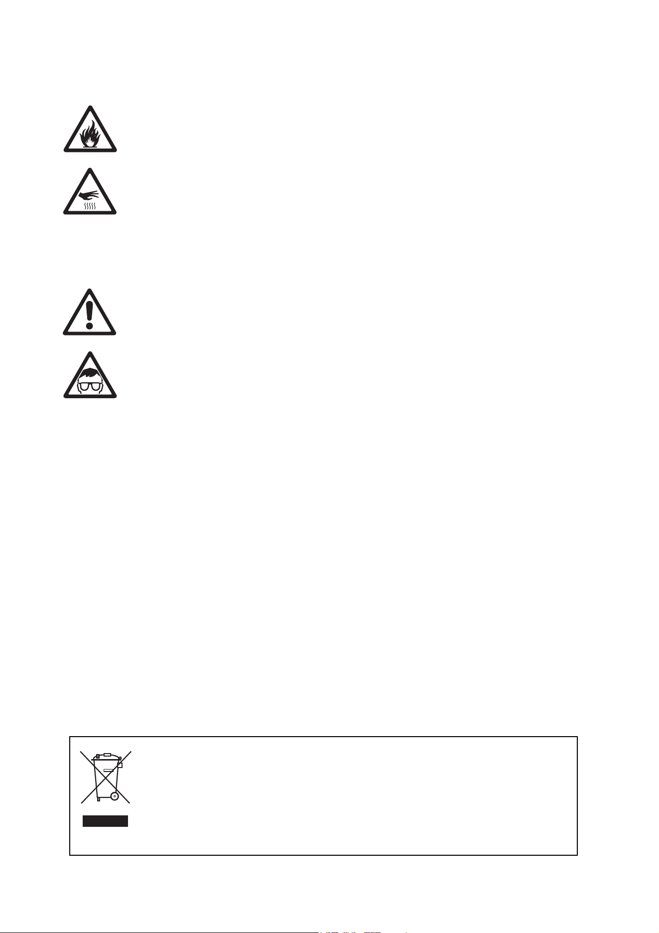
3. See Figure 1. Remove the eight Allen screws A that hold the front cover B, then remove the front cover
B and front cover seal C from the fixture housing F.
4. Using a T-bar or long Allen key, reach down into the housing and remove the four effects module
retaining screws D.
5. Lift the effects module up carefully. It is connected to the rest of the fixture by three multi-connectors.
Each connector has a different number of pins, so it is impossible to get them mixed up. Disconnect the
multi-connectors, then lift the effects module out of the fixture and place the module gently on a clean,
flat surface. You can now install color filters and rotating gobos.
Figure 1: Removing the front cover and effects module
A
B
C
D
E
F
Installing color filters and gobos 9
Installing color filters
To install a filter in the Exterior 400 Image Projector effects module:
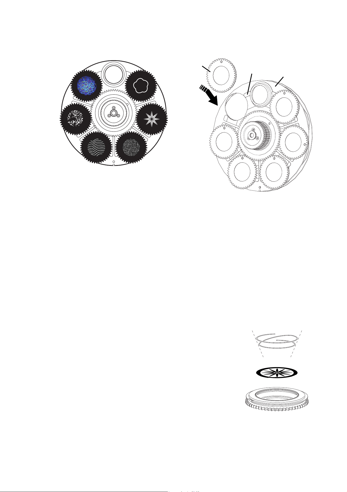
1. See Figure 2. Refer to the diagram for filter position numbers. The color wheel is shown from the rear
(the side facing the back of the effects module, away from the front cover). It will help you identify filter
positions if you note the position of the small magnet A on the color wheel opposite the open slot.
2. If a filter has already been installed, push it away from the color wheel towards the gobo wheel slightly to
release it, then grasp it by the edges and remove it. If your fingers are too large, protect the glass with a
piece of paper that has been folded several times and grasp the filter with needle-nose pliers.
3. To install a filter, push the filter B in between the color wheel C and the gobo wheel D and slide it under
the retention spring in the color wheel until it snaps into place on the color wheel and the raised lug E in
the filterholder engages in its cutout F.
1
2
3
4 5
6
7
8
9
Figure 2: Installing a color filter
Color filter positions
(color wheel seen from rear,
side facing towards LEDs)
A
B
D
C
E
F
10 Exterior 400 Image Projector user manual
Installing gobos
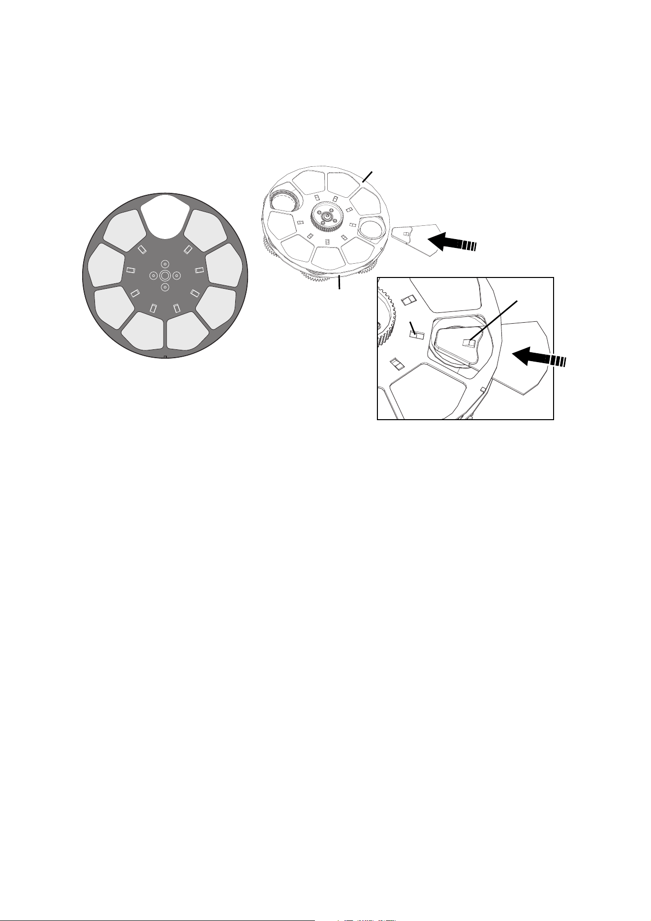
Most gobos must be installed facing in a certain direction in order to avoid heat damage. Follow the gobo
orientation guidelines given in Figure 3. Consult your Martin dealer or gobo supplier if you are in any doubt
about the orientation of a specific gobo type.
Coated Glass Gobos
Focus is easiest to maintain if all coated gobos in a fixture are installed with their coatings
as close as possible to the same plane of focus. However, the first priority is normally to
ensure that the more reflective side faces towards the LEDs.
More reflective side towards LEDs
To minimize the risk of gobo overheating and
damage, turn the more reflective side of a
coated gobo towards the LEDs.
Less reflective side away from LEDs
The less reflective side of a coated gobo will
absorb less heat if it faces away from the
LEDs.
To determine which side of a gobo is coated,
hold an object up to it. On the uncoated side,
there is a space between the object and its
reflection and the edge of the gobo can be
seen when looking through the glass.
Textured Glass Gobos
Smooth side towards LEDs Textured side away from LEDs
Textured glass gobos in the Exterior 400 Image Projector give the best focus results with
the smooth side towards the LEDs. If in doubt, consult your Martin dealer or gobo supplier.
Metal Gobos
Reflective side towards LEDs Black side away from LEDs
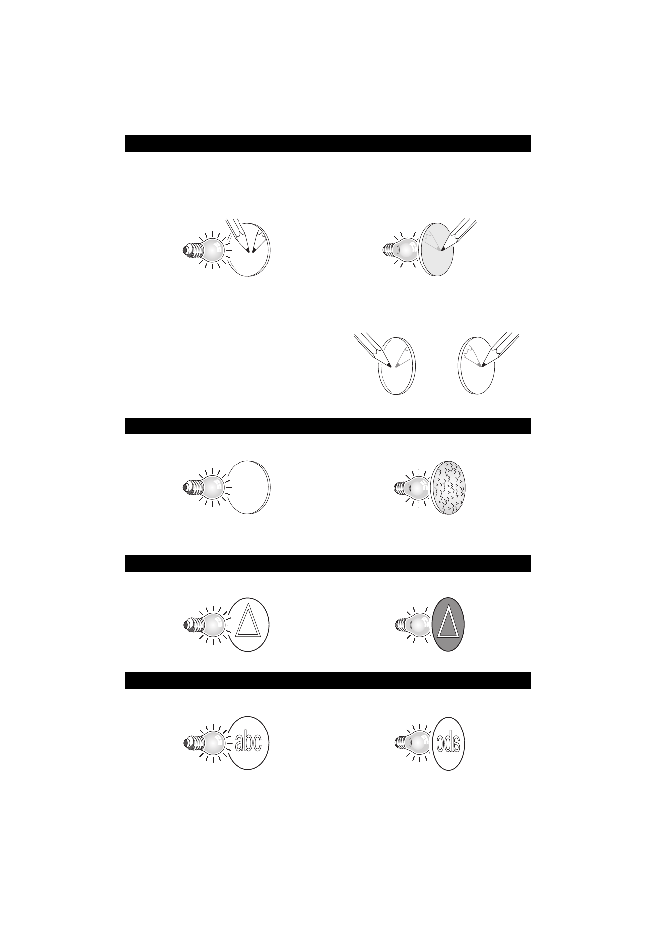
Image / text Gobos
True image towards LEDs
Reversed image away from LEDs
Custom gobos must be designed so that the true image appears on the more reflective side
so that it faces the LEDs when installed.
Figure 3. Correct gobo orientation
Uncoated side Coated side
Installing color filters and gobos 11
Gobo installation
Wear clean, lint-free cotton gloves while handling optical parts.
To install a rotating gobo in the Exterior 400 Image Projector effects module:
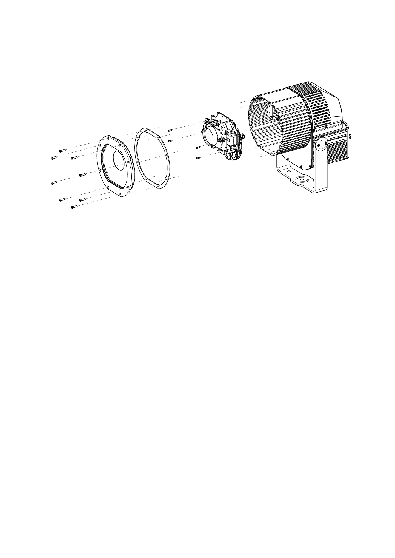
1. See Figure 4. Refer to the diagram for gobo position numbers. The gobo wheel is shown from the front
(the side facing the front of the effects module, towards the front cover). It will help you identify gobo
positions if you note the position of the small magnet A on the gobo wheel opposite the open slot. Rotate
the gobo wheel if necessary for access to the different gobo positions.
2. If a gobo has already been installed, lift it away from the gobo wheel slightly to release it from its cutout
in the gobo wheel, then hold it by the edges and slide it outwards.
3. To insert a gobo, slide the goboholder B onto the gobo wheel C, working it in so that the gobo retaining
clips D engage in the slot around the edge of the goboholder. If necessary, lever the clips away from the
wheel slightly with a small screwdriver or similar tool. Push the goboholder in until it snaps into place in
its cutout in the gobo wheel.
Replacing gobos in goboholders
Gobos in rotating goboholders are interchangeable and can be replaced
with gobos either supplied or specifically approved by Martin.
See Figure 5. Gobos are held in rotating holders by a retention spring.
Note that the retention spring can only be used with gobos maximum 3
mm thick. Thicker gobos can be glued to the holder with a UV adhesive or
Loctite 330 Multibond with Activator.
Important! A gobo can fall out of its holder if the spring is inserted the wrong
way round.
To replace a gobo:
1. Put on clean, lint-free gloves to protect your fingers and to avoid
contaminating optical components with grease and dirt.
2. Remove the goboholder from the gobo wheel as described in the
previous section.
3. With a small screwdriver or similar, unhook the end of the gobo spring
furthest from the gobo and pull out the spring. Drop the gobo out of the holder.
Figure 4: Installing a gobo
Gobo positions*
(gobo wheel seen from front of module
facing towards front cover)
A
B
D
C
61
2
34
5
*Gobos 5 (Tight Stripple) and 3 (Dots Breakup Small) are supplied pre-installed. Other gobos are examples only.
Figure 5: Rotating
goboholder

12 Exterior 400 Image Projector user manual
4. With reference to Figure 3 on page 10, insert the new gobo in the holder with the side that must face
towards the LEDs facing upwards, towards the spring.
5. Insert the spring with the narrow end against the gobo, as shown in Figure 5. To identify the narrow end,
press the spring flat: the narrow end is on the inside. Push the end of the spring in under the lip of the
holder.
6. Check that the gobo is seated flush against the holder. Press the spring as flat as possible against the
back of the gobo.
7. Install the goboholder in the gobo wheel as described in the previous section.
Reinstallation after accessing the effects module
To reinstall the effects module and front cover:
1. Lower the effects module into position in the housing. Note the number of pins in the multi-connectors to
the module and reconnect them.
2. See Figure 1 on page 8. Using a T-bar or long Allen key, reinstall the four effects module retaining
screws D.
3. Check the front cover seal C. If it is not in perfect condition, it must be replaced with a new item from
Martin™ to maintain the fixture’s IP65 rating.
4. Place the front cover B with its seal C in position on the front of the fixture housing F and insert the eight
Allen screws A. Tighten the screws until they are finger-tight only.
5. Using a torque driver, cross-tighten the screws gradually – tightening all screws opposite each other,
working around the cover in at least three stages – to a torque of 8 Nm (5.9 ft.-lbs.). Do not over-tighten,
or the front glass may break.
6. You can now either apply power or proceed with physical installation.
Physical installation 13
Physical installation
Warning! Read "Safety Information" on page 3 before installing the Exterior 400 Image Projector.
Warning! The safety and suitability of lifting equipment, installation location, anchoring method,
mounting hardware and electrical installation is the responsibility of the installer. All local safety
regulations and legal requirements must be observed when installing and connecting the Exterior
400 Image Projector. Installation must be carried out by qualified professionals only.
Contact your Martin supplier for assistance if you have any questions about how to install this
product safely or the suitability of an installation.
Location and orientation
Warning! The Exterior 400 Image Projector mounting yoke base must be securely anchored to a
suitable flat surface. Ensure that the supporting structure can bear the weight of all installed
devices plus an adequate safety margin.
Warning! If the fixture is to be installed in any location where it may fall and cause injury or damage
if the primary attachment fails, install an approved safety cable as described below.
Important! Make sure that there will be at least 0.1 m (4 ins.) of free space and unrestricted airflow around
the fixture.
Allow for service access to the front and rear of the fixture.
The Exterior 400 Image Projector can be installed outdoors. It has an IP rating of 65 and is designed to
withstand rain and other low-pressure water projections but:
• Install the fixture as shown in Figure 6 and Figure 7 (see page 14).
• Do not expose it to high-pressure water jets from any direction
• Do not immerse it in water (or any other fluid)
• Do not install it in a location where flooding may occur.
Ensure sufficient drainage to cope with the heaviest rainfall. Make sure that water can drain away from the
installation area at least as fast as it can enter it.
The Exterior 400 Image Projector requires free and unobstructed airflow around it to ensure adequate
cooling:
• Do not bury the fixture or locate it in an unventilated space
• Allow at least 0.1 m (4 in.) free space around the fixture
Install the fixture at least 0.5 m (20 in.)away from any combustible materials (wood, paper, etc.) and well
away from any flammable materials.
The aluminum housing reaches temperatures up to 65° C (149° F). Restrict public access or locate the
fixture so that it cannot accidentally be touched.
14 Exterior 400 Image Projector user manual
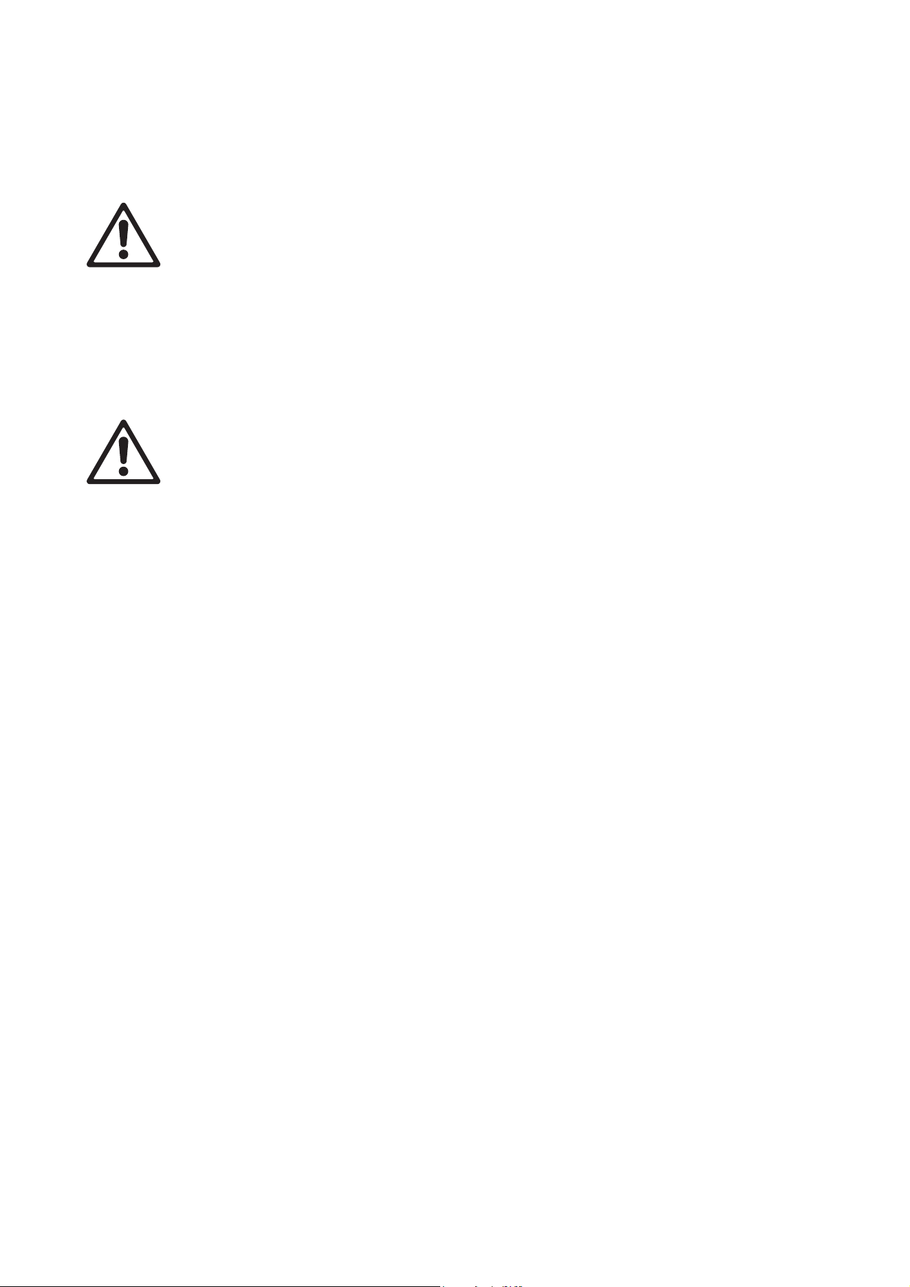
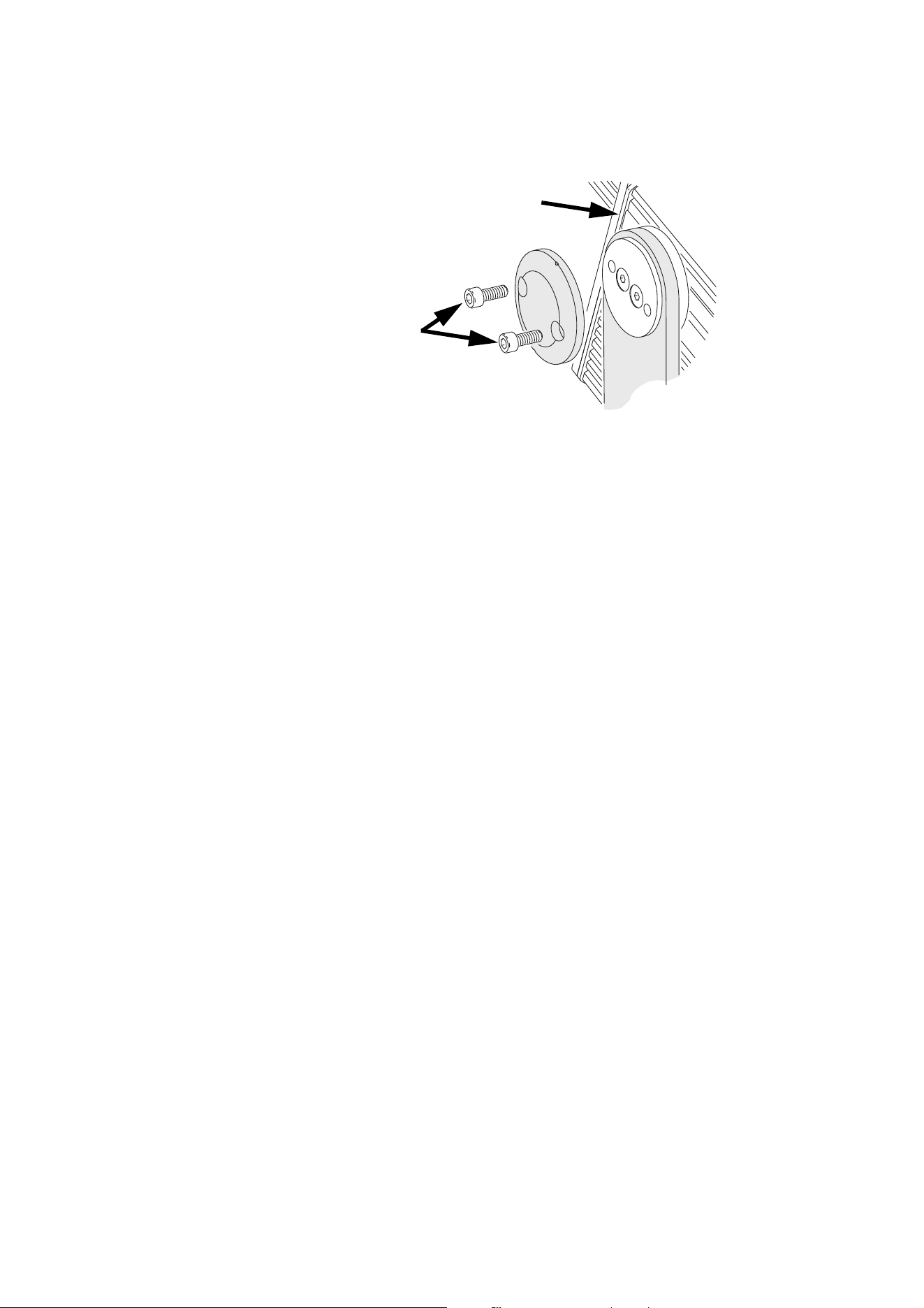
Mounting angle and avoiding damage to seals
See Figure 6 on right. If you install the
Exterior 400 Image Projector with its heat
exchanger air intake A pointing upwards and
its power box B below the main luminaire
housing, and if you point the luminaire from
approx. +5° to -95°, rainwater can collect on
top of the power box (see arrow). This can
immerse silicone seals in hot and cold water,
often mixed with pollutants, for long periods.
This can in turn cause damage and allow
water to enter the product.
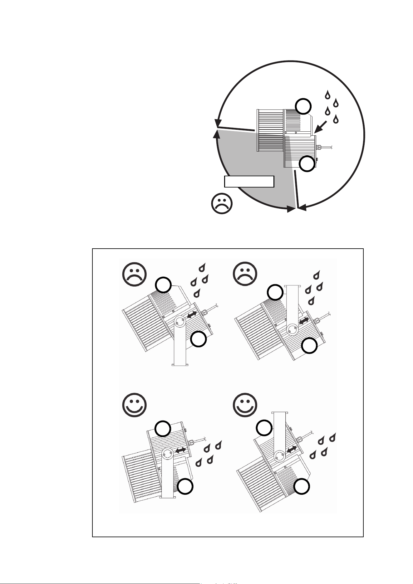
See Figure 7 below. If you install the Exterior
400 Image Projector with its light beam
pointing downwards, install it with its air
intake A facing downwards and its power box
B above the main housing so that water will
drain away from the top of the power box B.
Depending on whether you install the
luminaire in a standing or hanging position,
you may need to release the luminaire
completely from its mounting yoke, turn it so
that its power box B is above the main
luminaire housing, and then reinstall the
luminaire in its yoke.
Figure 6: Mounting angle 1
+5° to -95°
A
B
Figure 7: Mounting angle 2
A
A
AA
B
B
B
B
Physical installation 15
Fastening to a surface
Warning! All fasteners used to mount the Exterior 400 Image Projector must be corrosion-resistant
and strong enough to mount the fixture safely. The washers supplied with the fixture must be
installed directly under the fasteners’ heads when anchoring the yoke base to the installation
surface.
The yoke must be fastened to the installation surface using minimum three fasteners. If there is a
danger that the fixture may cause injury or damage if it falls, a securely anchored safety cable that is
approved for the weight of the fixture must be looped through one of the holes in the yoke base
marked A, B or C in Figure 8 on page 15.
The mounting yoke allows the fixture to be manually panned (i.e. rotated horizontally) and tilted for beam
aiming adjustment.
The mounting yoke base must be safely anchored to a horizontal surface. The number and type of fasteners
used will depend on the installation, but use at least three high-strength corrosion-resistant fasteners
(recommended minimum properties: stainless steel A4-70 grade according to ISO 3506 or steel grade 8.8
according to ISO 898-1). Any nuts used must be self-locking. Washers must be installed between the head
of each fastener and the yoke base. Suitable washers are supplied with the fixture.
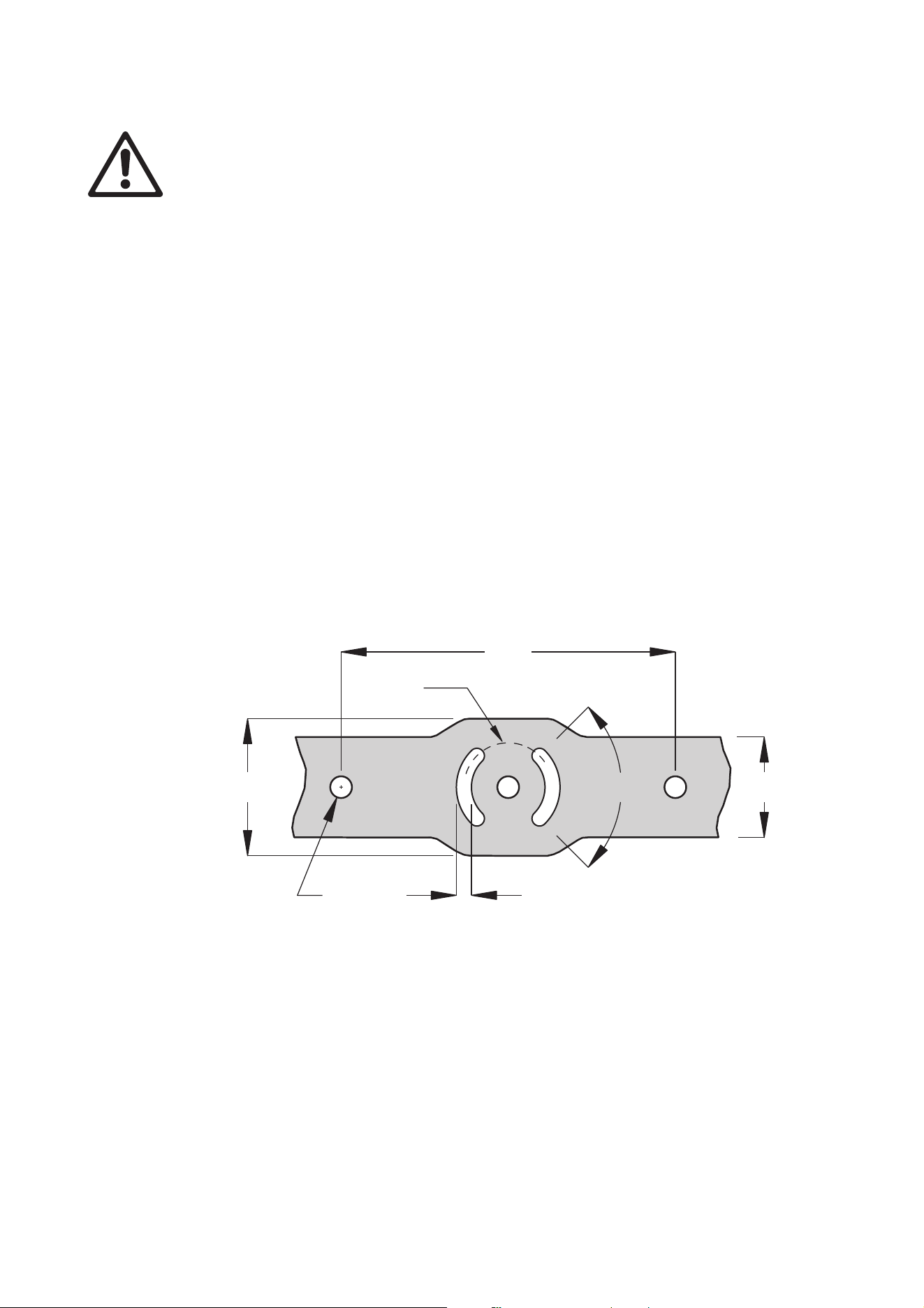
See Figure 8. To mount the fixture:
1. Attach a safety cable that is approved for the weight of the fixture to a secure anchoring point such as an
eyebolt in the installation surface and loop it through one of the holes in the yoke base shown as A, B or
C in Figure 6.
2. Fasten the yoke base to the mounting surface using a 12 mm (1/2 inch) shaft diameter bolt with a
washer in the center hole A.
3. Then either use two bolts with 12 mm (1/2 inch) shaft diameter and washers passing through holes B or
use two bolts with 8 mm (5/16 inch) shaft diameter and washers passing through slots C to secure the
fixture. Installing bolts through slots C will give approximately 90° of pan adjustment.
If additional bolts are required to mount the fixture safely, install bolts through holes B and slots C.
Tilt adjustment
Tilt-lock screws at either side of the mounting yoke allow adjustment of vertical beam aiming. It is possible to
slide the fixture in the yoke once the tilt-lock screws are loosened. This allows some extra clearance and
adjustment.
Important! Do not slide the fixture in the yoke so far that the yoke comes into contact with one of the silicone
seals between the aluminum elements in the housing, as this may make it impossible to achieve a
waterproof seal.
Tilt adjustment can be carried out with the fixture powered on. To adjust the tilt:
1. Put on heat-resistant gloves if the fixture is or has recently been powered on.
200
Ø53
82
Ø13
9
60
90°
Figure 8: Mounting yoke attachment points
A
BB
CC
16 Exterior 400 Image Projector user manual
2. See Figure 9. Loosen, but do not remove, the tilt-lock screws.
3. Tilt the fixture to the desired angle and slide it backwards or forwards in the yoke until its weight is evenly
distributed.
4. Retighten the screws.
tilt-lock screws
Figure 9: Tilt adjustment
silicone seal
Power and DMX data cable layout 17
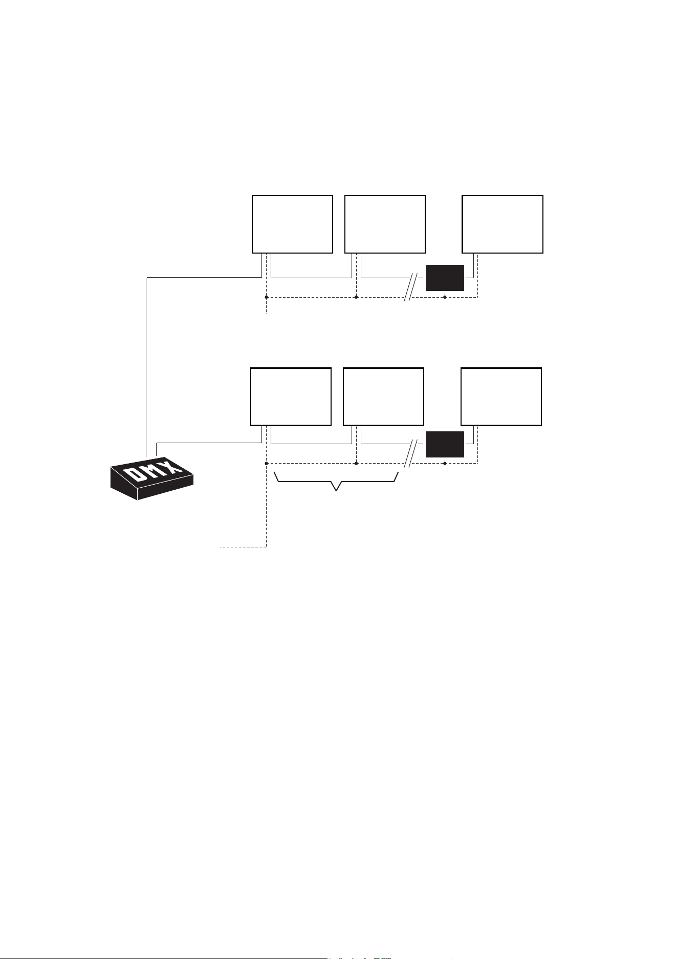
Power and DMX data cable layout
Figure 10 gives an overview of a suitable cable layout. The dotted lines represent AC mains
power circuits. The solid lines represent the data link.
OPTO-
SPLITTER
Power
230V AC
50 Hz50
Hz
Power
230V AC
50 Hz
Max. 32 luminaires
or 500m. before
opto-splitter
is required.
Max.
32 luminaires
or
500m. before
opto-splitter
is
required.
OPTO-
SPLITTER
DMX
Universe #1Universe
#1
DMX
Universe #2
AC power
Fixture Fixture Fixture
Figure 10: Schematic cable layout diagram
OPTO-
SPLITTER
Power
230V AC
50 Hz
Power
230V AC
50 Hz50
Hz
Max. 32 luminaires
or 500m. before
opto-splitter
is required.
OPTO-
SPLITTER
DMX
Universe #1
DMX
Universe #2Universe
#2
AC mains power
Fixture Fixture Fixture
OPTO-
SPLITTER
Power
230V AC
50 Hz50
Hz
Power
230V AC
50 Hz
Max. 32 luminaires
or 500m. before
opto-splitter
is required.
Max.
32 luminaires
or
500m. before
opto-splitter
is
required.
OPTO-
SPLITTER
DMX
Universe #1Universe
#1
DMX
Universe #2
AC mains power
Fixture Fixture Fixture
18 Exterior 400 Image Projector user manual
AC mains power
Warning! Read “Safety Information” on page 3 before installing, powering, operating or servicing
the Exterior 400 Image Projector.
Warning! Electrical installation must be carried out by qualified professionals only.
See Figure 10 on page 17 for a schematic diagram of cable layout. If you require help in planning or
dimensioning the power distribution system, please contact your Martin supplier for assistance.
If there is a break or cut at any point in a cable (for example at a connection point), and if this is exposed to
water, moisture can be drawn up the inside of the cable due to the vacuum effect of temperature fluctuations
during operation. Ensure that the fixture is protected from the entry of water via the power cable by using
IP65-rated connectors or junction boxes, or by protecting connectors with weatherproof housings.
The Exterior 400 Image Projector is supplied in EU and US models. Both models accept AC power at
100-240 V nominal, 50 or 60 Hz. Do not connect to power at any other voltage or frequency.
Power is applied to the Exterior 400 Image Projector as soon as it is connected to power. Provide a means
to disconnect from power or shut down power to fixtures that is easily accessible and is located close to the
fixtures.
Connecting to power
The fixture is supplied with a power cable tail installed ready for connection to a single-phase 3-wire (live,
neutral, ground/earth) AC mains power distribution system at 100-240 V nominal, 50/60 Hz. Terminal blocks
or suitable connection devices must be provided by the installer.
Danger! Lock out power to the entire installation before working on cables and connections.
Warning! If you have any other type of distribution system than the one listed above, contact Martin
for assistance.
Warning! Make sure that cable connections are totally protected from water in approved enclosures
such as sealed junction boxes or sealed cable connectors, or moisture may be drawn up the inside
of the cable by the vacuum effect that results from heating and cooling during operation. Follow the
safety precautions and instructions provided by the enclosure supplier.
Warning! If the supplied power cable is unsuitable for any reason, contact your Martin supplier for
replacement. Exterior 400 Image Projector power and data cables may be installed or replaced only
by Martin or its authorized service agents.
To connect to a single-phase 3-wire (live, neutral, ground/earth) power system:
1. Lock out power to the installation.
2. Prepare a suitable junction box or sealed cable connector.
3. The power cable color coding for US and EU models is given in Table 1. Connect the conductors in the
power cable to the distribution circuit as follows:
- Connect the green wire (US models) or yellow/green wire (EU models) to ground (earth)
- Connect the white wire (US models) or blue wire (EU models) to neutral
- Connect the black wire (US models) or brown wire (EU models) to live.
Wire color
(US models)
Wire color
(EU models) Conductor Symbol Screw (US)
black brown live L yellow or brass
white blue neutral N silver
green yellow/green ground (earth) or green
Table 1: Conductor identification

AC mains power 19
4. Check that cable connection enclosures are sealed, check that all installation work is completed, and
carry out appropriate tests and safety checks before applying power.
Power plug (not North America)
In regions outside North America, legislation or building codes may allow the installation of a power plug
that is suitable for local AC mains power outlets and approved for the installation environment on the
supplied power cable. If you choose to do this, install a grounding-type (earthed) plug that is rated 5 A
minimum, following the plug manufacturer’s instructions. Table 1 on page 18 shows some possible pin
identification schemes; if pins are not clearly identified, or if you have any doubts about proper installation,
consult a qualified electrician. Ensure that all connections are protected from water, moisture, dirt, etc.

20 Exterior 400 Image Projector user manual
Control data link
E
xterior 400 Image Projector fixtures must be connected via a control data link for DMX controller or
synchronized (master/client) operation.The following considerations must be taken into account
when planning the data link:
• RS-485 data cable designed for exterior use is required for outdoor installations. RS-485 cable has low
capacitance and a characteristic impedance of 85 to 150 Ohms. It is electrically shielded and has at least
1 twisted pair of conductors. The minimum recommended wire size is 0.25 mm
2
(24 AWG) for runs up to
300 meters (1000 ft.) and 0.32 mm
2
(22 AWG) for runs up 500 meters (1640 ft). CAT 5 network cable
designed for direct burial can be used in outdoor installations, but you are recommended to run it inside
conduit.
• The maximum permitted control data cable length before a control signal amplifier is required is 500
meters (1640 ft.).
• Fixtures must be ‘daisy-chained’, i.e. the data cable must be connected in one single chain of fixtures as
shown in Figure 10 on page 17.
• Each chain may connect a maximum of 32 fixtures. After this the signal must be amplified.
• An optically isolated amplifier-splitter such as the Martin DMX 5.3 Splitter™ (P/N 90758140) or Martin
RDM 5.5 Splitter™ (P/N 90758150) must be used to:
- extend a link beyond 500 meters (1640 ft.)
- extend the link to include a further maximum 32 fixtures, or
- branch the link into further single chains, each containing 32 fixtures. The Martin Splitters mentioned
above allow a link to be branched into five new chains.
• Each chain on the link must be terminated by placing a 120 ohm resistor (available from Martin,
P/N 04150308) across the data hot (+) and cold (-) conductors of the last fixture on the chain.
• Long parallel runs of AC power and control data cables may cause interference on the data link and must
be avoided. Even if not required by law, use separate conduits for power and data cables.
• One DMX universe has 512 DMX control channels available. If individual control of the fixtures in an
installation is required, each fixture must be given its own channels until the limit of 512 is reached. At this
point, a new DMX universe must be created before more fixtures can be added.
• An Exterior 400 Image Projector requires nine DMX channels. The total number of Exterior 400 Image
Projectors that can be linked in one DMX universe will therefore be 512 / 9 = 56 (note that an
amplifier-splitter must be used each time the limit of 32 devices on one branch is reached).
Connection pinouts
XLR connection
XLR connectors are suitable if DMX cable is used for the data link. XLR pin numbers are normally marked
on connectors. Connectors must be wired using the standard DMX/RDM pin-out:
• Pin 1: Cable shield
• Pin 2: DMX/RDM Data 1 - (cold)
• Pin 3: DMX/RDM Data 1 + (hot)
Pins 4 and 5 on 5-pin XLR connectors are not used by DMX or RDM signals but are available for special
Data 2 connections. If used, they must be wired as follows:
• Pin 4: Data 2 - (cold)
• Pin 5: Data 2 + (hot)
To avoid ground/earth loop interference, ensure that the DMX cable shield does not come into contact with
the shell or body of XLR connectors.
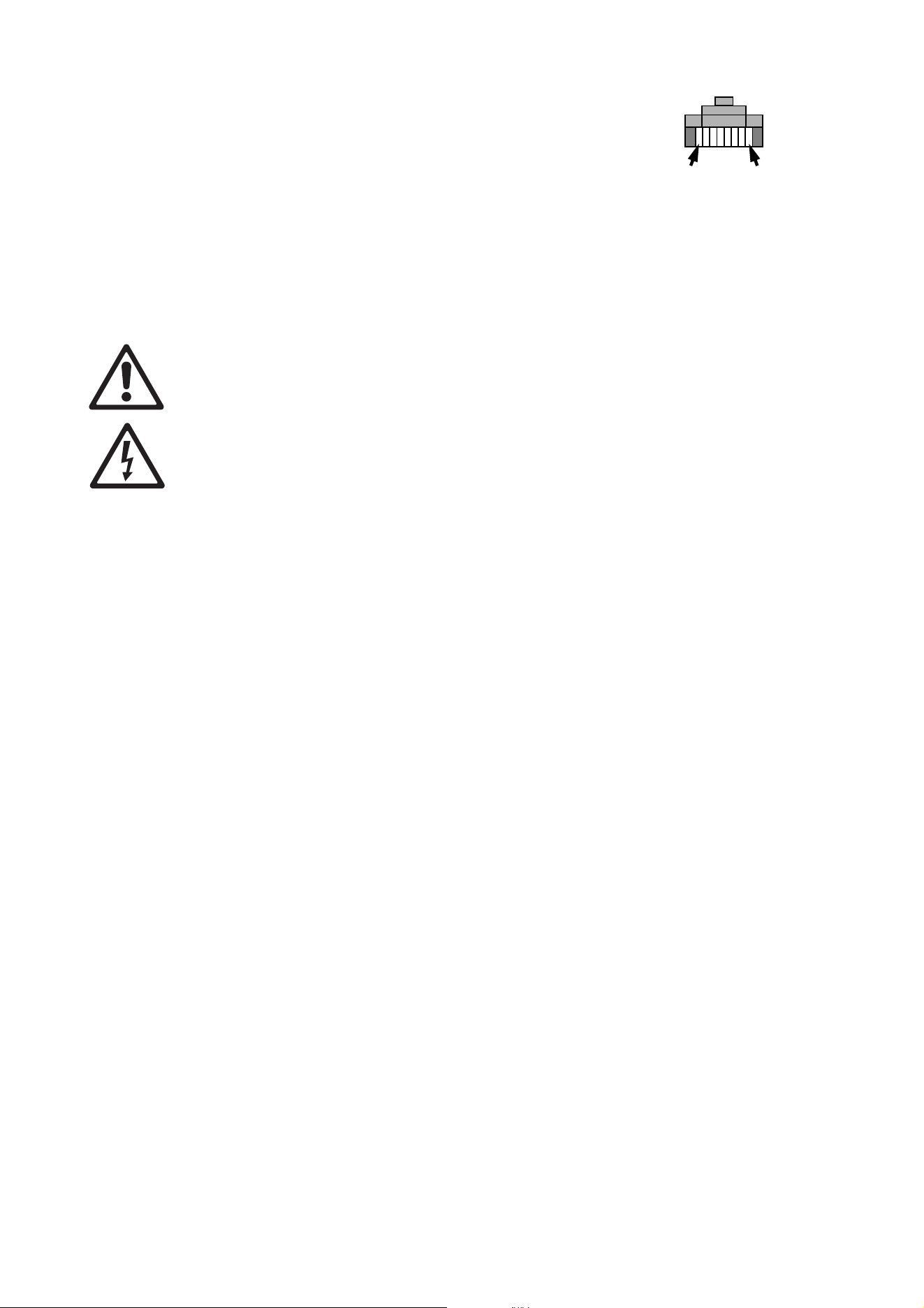
RJ-45 connection
RJ-45 connectors are suitable if CAT 5 cable is used for the data link. RJ-45 cable connector pins are
numbered from the left looking at the face of the connector with the locking clip on top (see Figure 11).
Connectors must be wired according to the 568-B system using the standard RJ-45 pin-out for DMX
applications:
• Pin 1 (White/orange): DMX/RDM data hot (+)
• Pin 2 (Orange): DMX/RDM data cold (-)
Control data link 21
• Pins 7 (White/brown) and 8 (Brown): Common
Pins 3 and 6 are available for Data 2 connections. If used, they must
be wired as follows:
• Pin 3 (White/green): Available for Data 2 hot (+)
• Pin 6 (Green): Available for Data 2 cold (-)
Pins 4 and 5 are not used in currently available lighting control
systems but can be wired as follows:
• Pin 4 (Blue)
• Pin 5 (White/blue)
Connecting the data link
Danger! Lock out power to the entire installation before working on cables and connections.
Warning! Make sure that cable connections are totally protected from water in approved enclosures
such as sealed junction boxes or sealed cable connectors, or moisture may be drawn up the inside
of the cable by the vacuum effect that results from heating and cooling during operation. Follow the
safety precautions and instructions provided by the enclosure supplier.
Warning! If the supplied power cable is unsuitable for any reason, contact your Martin supplier for
replacement. Exterior 400 Image Projector power and data cables may be installed or replaced only
by Martin or its authorized service agents.
The Exterior 400 Image Projector is supplied with a 1.8 meter (5.9 ft.) data cable tail for DMX/RDM data
connection. The cable contains both data input and output cables. Conductors are identified as follows:
Data input
• Black wire = data input hot (+ve)
• Red wire = data input cold (-ve)
• Wire without insulation = data input shield/drain
Data output
• White wire = data output hot (+ve)
• Green wire = data output cold (-ve)
• Wire without insulation = data output shield/drain
To connect a fixture to the data link:
1. Connect the conductors in the fixture’s cable tail to the data circuit respecting the above color code. If
required, install input and output connectors on the data cable respecting the pinouts described in
“Connection pinouts” on page 20. Standard procedure is to use a male connector on a fixture’s cable tail
for data input and a female connector for data through/output. Do not connect the shield conductor to
ground (earth) or allow it to come into contact with a connector shell, as this may cause interference.
2. Check that cable connection enclosures are sealed, check that all installation work is complete, and
carry out appropriate tests and safety checks before applying power.
Pin 1 Pin 8
Figure 11: RJ-45 cable
connector pins

22 Exterior 400 Image Projector user manual
Effects
This section describes the effects available in the Exterior 400 Image Projector. Details of controlling effects
via DMX are given in “DMX protocol” on page 36. Details of programming effects in stand-alone operation
are given in “Stand-alone operation” on page 27.
Electronic shutter effect
The electronic shutter effect uses the LEDs to provide instant open and blackout as well as variable speed
regular and random strobe, and opening/closing pulse and sinewave intensity modulation effects.
Electronic dimming
The LEDs can be dimmed smoothly from 100% to zero. Note that four different dimming curves can be
selected using the Martin MUM™ application (see “Dimming curve options” on page 25) or via DMX on the
fixture control channel 9.
Color wheel
The color wheel can be scrolled continuously (giving split colors), scrolled in steps (giving full colors only)
set to continuous rotation or set to random color chases (auto-trig).
Rotating gobo wheel
Any of the six rotating gobos can be selected at an indexed angle, rotated, or shaken from side to side at an
indexed angle or while rotating. The entire gobo wheel can also be scrolled continuously.
Iris
The motorized iris can be opened or closed smoothly, with pulse effects also available.
Focus
The motorized focus system can be varied from infinity to approximately 2 meters (6.4 feet).
Fixture setup 23
Fixture setup
You can set up Exterior 400 Image Projector fixtures for DMX control and/or set up stand-alone operation
using the Martin MUM™ Windows application. MUM lets you communicate with one fixture at a time
You can also set up fixtures for DMX control using an RDM (Remote Device Management) compliant DMX
controller such as the Martin M1™ console or the Martin M-PC™ WIndows application. An RDM-compliant
DMX controller connected to the data link lets you set up all the fixtures on the link.
Setting up using MUM
The Martin MUM™ (Multi-Utility Manager) application allows you to program and configure Martin Exterior
400 Image Projector fixtures from a laptop PC and features an intuitive GUI (graphic user interface).
Tip! Using MUM, you can connect to and set up one fixture at a time. It is therefore most convenient
if you set up and program the fixture before it is installed.
Refer to the MUM user manual for instructions on installing and starting the MUM application.
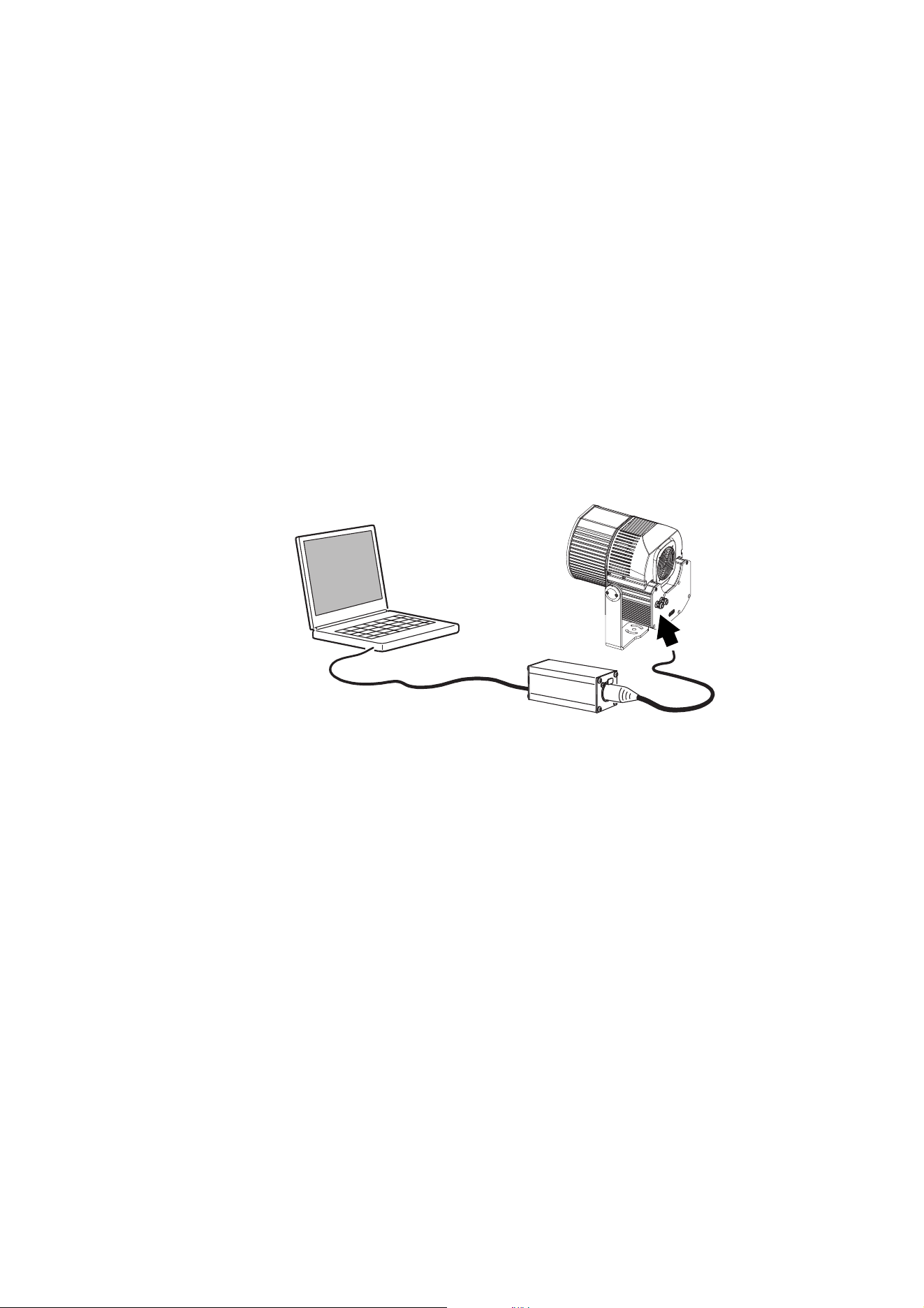
Connecting a PC with MUM
To connect a PC running MUM to an Exterior 400 Image Projector:
1. Obtain the Martin MUM application, a Martin DABS 1 interface box and interface cables. These are
available as a set, P/N 90758090, from Martin. If your version of MUM does not cover the Exterior 400
Image Projector, download the ‘Martin DMX Tools’ software package from the Martin website at
www.martin.com. This package includes the latest version of MUM that covers the Exterior 400 Image
Projector. The download is free of charge.
2. Connect the DABS 1 to your PC using the supplied USB cable.
3. Connect the DABS 1’s XLR output to the Exterior 400 Image Projector via the data link. Note that you
may only connect to one fixture at a time.
4. Apply power to the fixture and start the MUM application. The application will automatically detect the
fixture if it is powered on and correctly connected. It will also retrieve and display information and current
settings from the fixture.
Figure 12: Connecting to a PC with MUM
24 Exterior 400 Image Projector user manual
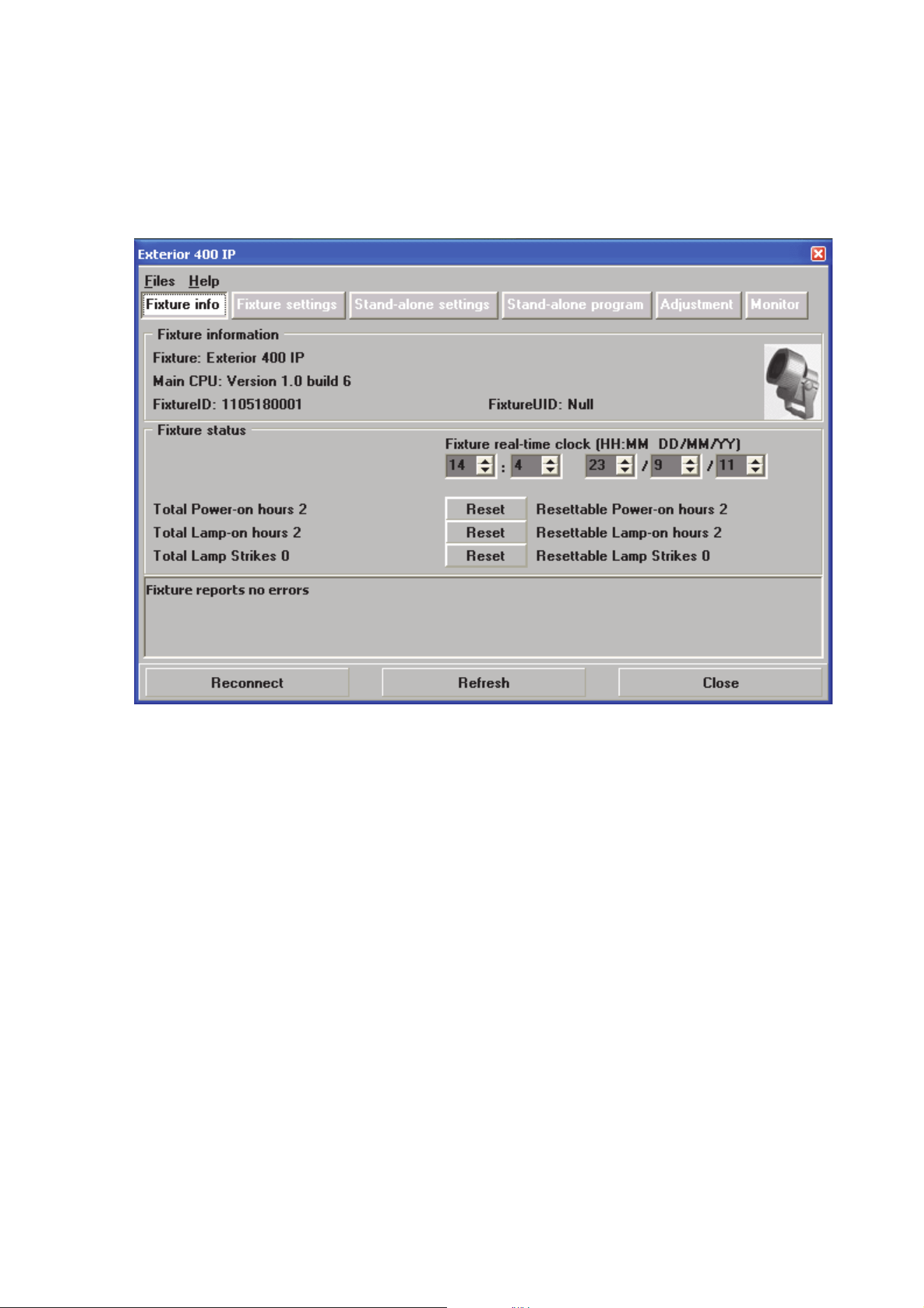
Configuring a fixture with MUM
Setting the clock
Exterior 400 Image Projector fixtures have a battery-operated 24-hour clock that is used to start and stop
stand-alone operation.
To set the clock:
1. Click on the Fixture Info button in MUM:
2. Using the Fixture real-time clock spin buttons, set the fixture to the current time (expressed in the
24-hour clock in hours and minutes) and date. The time will be updated in the fixture in real time.
DMX address and other fixture settings
If individual control of each Exterior 400 Image Projector fixtures is required, each fixture must be set up to
receive instructions from the DMX controller on a group of DMX channels that are not used by any other
device in its DMX universe. The DMX address, also known as the control address or start channel, is the
first of these channels. Each fixture uses this channel and the channels immediately above it to receive
instructions.
Exterior 400 Image Projector fixtures use nine DMX channels. If a fixture’s DMX address is set to 1, it will
use channels 1 - 9. Channel 10 will be available as the DMX address for the next fixture, which can use
channels 10 - 18, and so on.
If two or more identical fixtures are set up with the same DMX address and in the same DMX mode, they will
receive the same instructions and behave identically. Setting up identical fixtures with the same address is a
good tool for troubleshooting unexpected behavior and an easy way to achieve synchronized action.
Figure 13: Fixture info window
Fixture setup 25
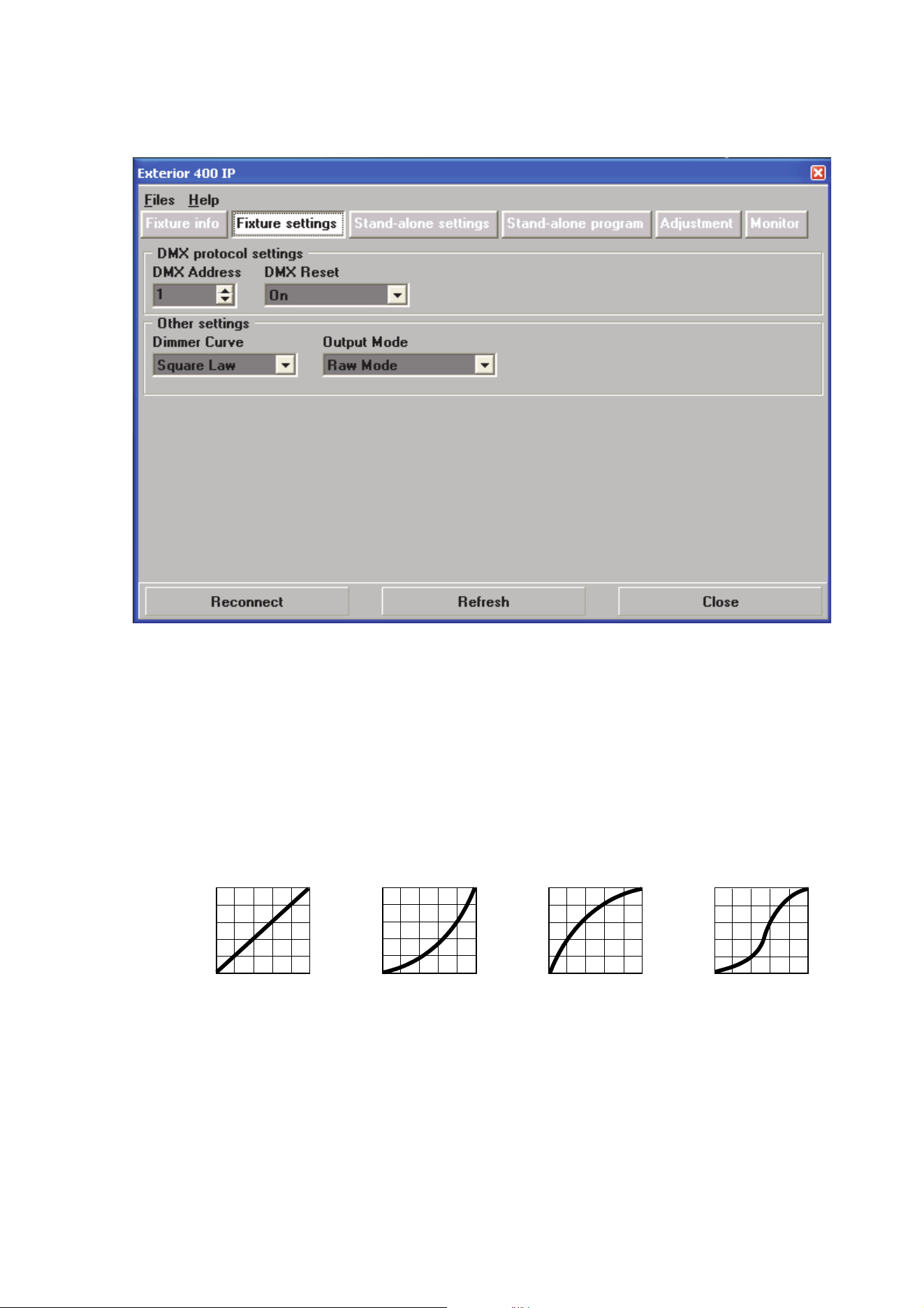
Setting DMX Addresses
To set a DMX address using MUM, click on the Fixture settings button and use the DMX Address spin
buttons to set the fixture’s DMX address. The DMX address will be updated in the fixture in real time.
DMX reset
Three settings are available in DMX Reset:
• On – The fixture will accept a reset command sent via DMX on channel 9 (the “Fixture control settings”
channel: see page 37). This can be a useful ‘escape route’ if you have had problems programming the
fixture correctly or a minor software problem has occurred.
• Off – Resetting via DMX is disabled to prevent accidental resets.
• 5 Sec – A reset command sent on DMX channel 9 must be sent for five seconds to reset the fixture.
Dimming curve options
The Dimming Curve setting provides four dimming options (see Figure 15):
• Linear – Optically linear: the increase in light intensity appears to be linear as DMX value is increased.
• Square Law – Light intensity control is finer at low levels and coarser at high levels.
• Inverse Square Law – Light intensity control is coarser at low levels and finer at high levels.
• S-Curve – Light intensity control is finer at low levels and high levels and coarser at medium levels.
Figure 14: Fixture settings window
Output
DMX % DMX %DMX % DMX %
Output
Output
Output
Linear S-CurveSquare Law Inverse Square Law
Figure 15: Dimming curve options

26 Exterior 400 Image Projector user manual
Raw and calibrated modes
The Output Mode setting lets you set the fixture to raw or calibrated output:
• Raw – Maximum LED light output is available but intensity may differ very slightly between fixtures
• Calibrated – LED light output is limited very slightly to ensure that intensity is the same in different
fixtures.
Setting up via RDM
The Exterior 400 Image Projector is compatible with RDM (Remote Device Management). Using an
RDM-compliant DMX controller such as the Martin M-PC™ Windows application, you can communicate
with all the fixtures on a data link via RDM without needing to connect to each fixture individually. You can
set the DMX addresses of all the fixtures on the link, carry out basic configuration and retrieve basic fixture
data.
To use Martin M-PC, connect a PC running this application to the data link via the Martin USB Duo™
USB/DMX interface box. Before you can communicate with fixtures, you will need to send a Scan command
from M-PC to detect the devices on the data link.

Operation 27
Operation
Exterior 400 Image Projector fixtures can be operated using a DMX controller or programmed to run a
stand-alone light show that does not require DMX control.
If a fixture has been set up to run stand-alone operation, it will follow its program according to its
programmed times as soon as powered is applied, unless it receives DMX commands. DMX commands
sent to a fixture override its stand-alone program.
Ambient temperatures
The Exterior 400 Image Projector can be operated at ambient temperatures from -30° C (-22° F) minimum
to 45° C (113° F) maximum.
Important! If the ambient temperature falls – or is forecast to fall – below 0° C (32° F), leave the
Exterior 400 Image Projector permanently powered on, even if LEDs are dimmed to zero. This will
provide heat and help protect circuits and components from the effects of low temperature. Starting
a fixture that is below 0° C (32° F) may cause damage to moving parts that is not covered by the
product warranty.
DMX control
The industry-standard DMX system allows remote control of the Exterior 400 Image Projector over the DMX
data link using a DMX controller or a PC running DMX controller software. such as the Martin M-PC™
application. If Luminaires have been set up with individual DMX addresses, they can be controlled
individually.
The section “DMX protocol” on page 36 gives details of the control options available using DMX.
Stand-alone operation
In stand-alone operation, the fixture displays effects that change at variable intervals and speeds, either as
soon as power is applied or for one or two periods during a 24-hour period. All parameters are
programmable. The term stand-alone means that the Exterior 400 Image Projector is not connected to a
control device, but is pre-programmed with a sequence of up to 100 scenes that play continuously in a loop.
28 Exterior 400 Image Projector user manual
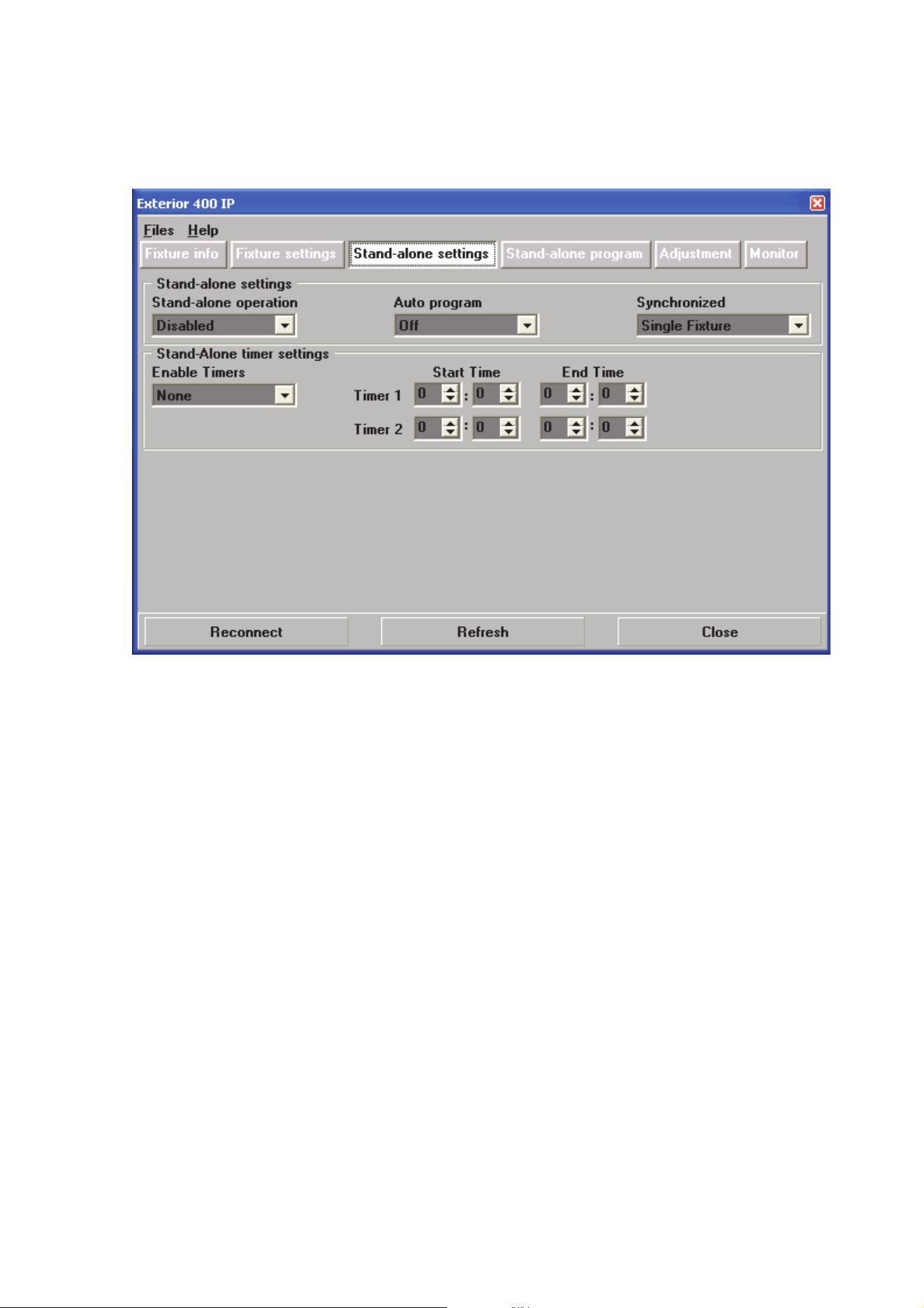
Configuring stand-alone settings
First, the fixture needs to be configured to know if and when to activate a stand-alone program. Connect a
PC running the Martin MUM™ application as described in "Connecting a PC with MUM" on page 23, and
click on the Stand-alone settings button (see Figure 16).
Stand-alone operation can be set to either:
• start automatically as soon as power is applied, or
• respond to a timer trigger that activates operation for one or two periods in a 24 hour period.
Enabling stand-alone operation
To enable stand-alone operation, set Stand-alone operation to Enabled.
Starting automatically
To set stand-alone operation to start automatically, set Auto program to On. The fixture will now start
stand-alone operation automatically as soon as power is applied and no DMX signal is being received.
Setting a timer trigger
To set a timer trigger:
1. Make sure the correct time has been set on the luminaire’s built-in clock (see "Setting the clock" on page
24).
2. Select None, Timer 1, Timer 2 or Both Timers in the Enable Timers box.
3. Use the Start Time and End Time spin buttons to set a period of stand-alone operation on the selected
timer(s).
Figure 16: Stand-alone settings window
Operation 29
Programming stand-alone operation
About scenes
A stand-alone light show consists of scenes. Each scene is a
particular lighting effect with predetermined gobo selection, focus,
color, intensity, iris and shutter effects, and duration. Up to 100
scenes can be programmed into the Exterior 400 Image Projector’s
program memory.
Each scene has a dynamic part – the fade – during which effects
move to the scene’s programmed positions, and a static part – the
wait – where effects do not change.
The duration of the fade and wait is programmed individually for
each scene. The fade time may be 0 - 120 seconds; the wait time
may be 1 second to 12 hours. The total time it takes a scene to
execute is the sum of the fade and wait times.
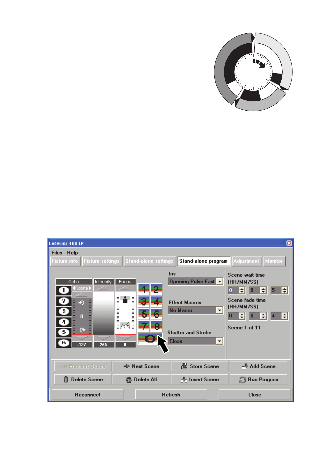
Programming scenes
To program a scene:
1. See Figure 18. Click on the Stand-alone program button.
2. In the Gobo section, clicking on a number to select a gobo slot and move the Rotate fader to select
rotation direction and speed.
3. In the Intensity section, move the fader to the desired output intensity.
4. In the Focus section, move the fader to adjust focus.
5. Select a color filter slot in the color filter section (arrowed). 0 is the open position (no color filter).
6. The Iris and Shutter and Strobe options available match those listed in the “DMX protocol” section
starting on page 36.
7. The Effect Macros are pre-programmed combinations of the fixture’s effects that give immediate access
to different types of action. Setting the same Effect Macros in multiple fixtures can help you make sure
that scenes are the same in those fixtures.
8. Select a wait time and a fade time for the scene.
Fade
Fade
S
c
e
n
e
1
S
c
e
n
e
1
S
c
e
n
e
3
S
c
e
n
e
3
S
c
e
n
e
2
S
c
e
n
e
2
Wait
Wait
Wait
Fade
Figure 17: Scene timing
Figure 18: Stand-alone programming window

30 Exterior 400 Image Projector user manual
Scene management
Once you have specified values for the effects and fade and wait times for the scene, you can store and
manage scenes using the commands available at the bottom of the Stand-alone program window (see
Figure 18):
When the program is run by applyi
ng the Run program command, scenes execute in a continuous,
ascending loop.
Synchronizing stand-alone operation
If you are running multiple fixtures on a data link, you can synchronize action so that all fixtures start their
programmed shows and start fading to the next scene at the same time.
Setting master and client fixtures
In synchronized operation, one fixture is set as the master and the others are set as clients. Each fixture
must be programmed with its own show. When the master fades to the next scene or starts its show from
the beginning again, it tells each client fixture to fade to its next scene or start its show again. In other
words, each client fixture will run its show repeatedly in a cycle, changing scene when prompted to by the
master, until the master finishes its own show and signals that all fixtures should start from the first scene
once again.
Before running synchronized operation, you must set fixtures to one of the following in the Synchronized
drop-down dialog box (see Figure 16):
• Sin
gle Fixture – Operates in stand-alone mode independently of other fixtures
• Master – Sends trigger signals to other fixtures, or
• Synchronized – Sets fixture as a ‘client’ that receives trigger signals from a master fixture.
No more than one fixture may be
the master. Any fixture on the link, regardless of its position, may be
the master. All other fixtures must be set as clients.
Stand-alone programming tips
If you want to keep things as simple as possible when programming synchronized operation, ensure that:
1. Ever
y fixture has the same number of scenes.
2. Scene times are a few seconds longer on the master fixture than on client fixtures (this will ensure that
client fixtures always have time to finish scenes before the master tells them to start the next scene).
It is important to note that the only commands transmitted by the master are scene change and show start
commands. No data about the appearance of the scene is transmitted between fixtures.
Store scene Save settings in the current scene.
Add scene Save settings in a new scene at the end of the current sequence of
scenes.
Insert scene Save settings in a new scene before the current scene. Tip: Think of
the Add and Insert commands as Save commands, to be used as the
last step after programming all effects.
Delete scene Remove the current scene from memory. Scenes after the deleted
scene are renumbered.
Next scene Step to the next scene.
Previous
scene
Step to the previous scene.
Delete all Remove all scenes from the fixture’s memory.
Run program Run the scenes in the programmed light show.
Operation 31
I
f you are programming a
group of fixtures to perform
the same scenes with
synchronized master/client
triggering, we recommend
that you:
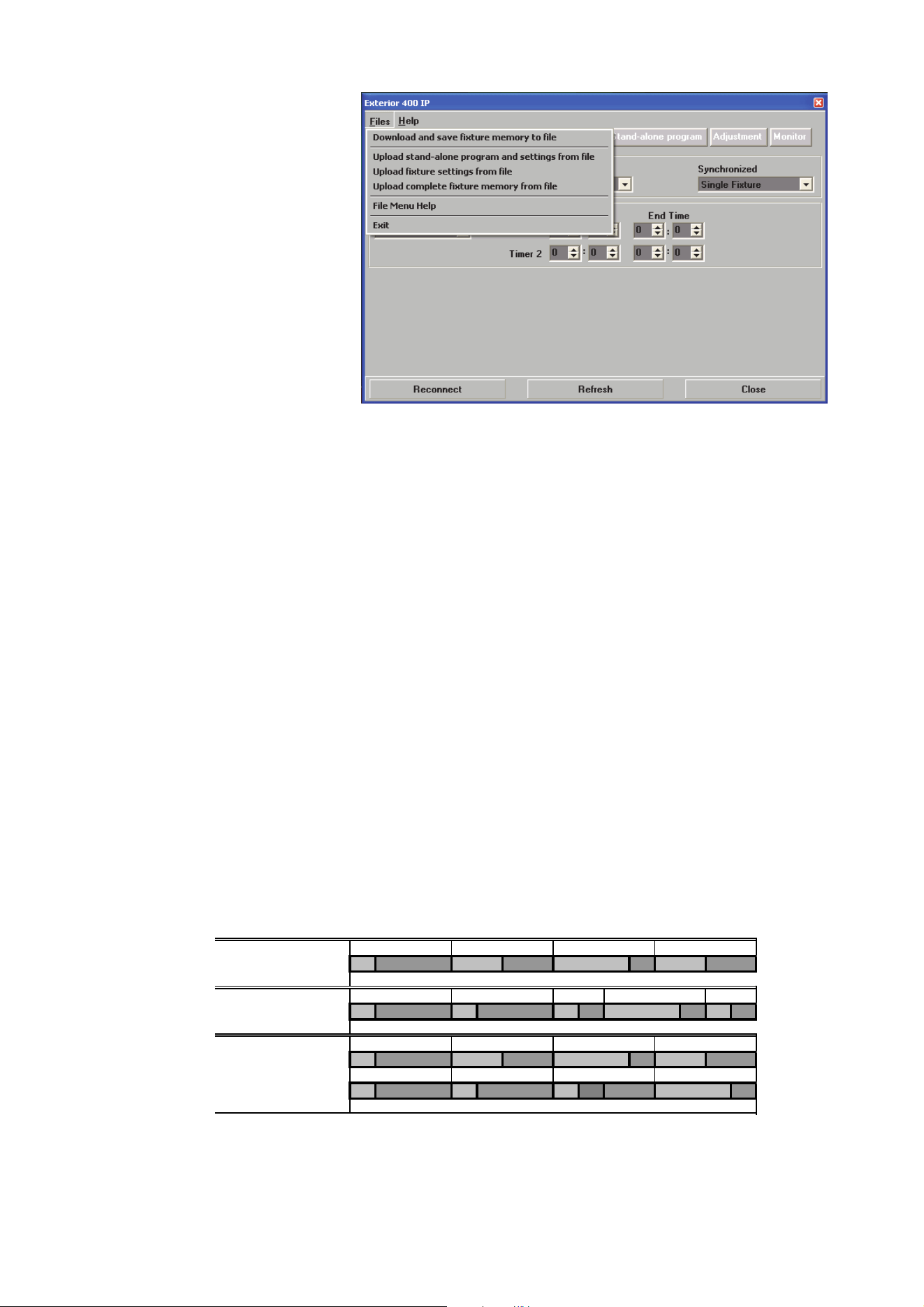
1. U
se MUM to program a
show on one client
fixture
2. Download and save this
fixture’s memory
(program and settings)
to your PC using
MUM’s Files menu (see
Figure 19), and then
3. Upload the program
and settings to each
subsequent fixture that
you connect to.
For a more detailed
explanation of
synchronized operation
and how advanced effects
can be created by programming fixtures with a different number of scenes, see the next section.
Synchronized stand-alone operation: detailed description
Note: This section gives advanced information about stand-alone synchronized operation. You only need
to read it if you require help with problem diagnosis or if you want to program advanced
synchronized light shows.
The principles in stand-alone synchronized operation are as follows:
1. A
scene contains a fade section, followed by a wait section
2. Each fixture can be individually programmed with up to 100 scenes, and each scene can have its own
individual fade and wait times.
3. Scenes are numbered from 0 to 99.
4. In synchronized operation, one master fixture issues commands to the other client fixtures to “go to
scene xx”, where xx is the scene number that the master will execute next.
5. If a client has fewer scenes than the master, it will derive which scene to go to by dividing the number of
the scene it has been commanded to go to (scene 5, for example) by the total number of scenes that the
client fixture has (4, for example) in whole numbers (no decimal places). In this example 5 divided by 4
results in 1, with 1 remainder. This remainder will be the number of the scene that the client fixture starts
- scene 1. Generally though, when a Client fixture reaches its own last scene before the Master fixture, a
“go to scene xx” message will result in the first scene being played.
6. If a client has more scenes than the master calls, the last scenes in the client will never be executed, as
is the case with scene S4 in the following example.
7. I
n synchronized operation, the wait time is determined by the master. Every client fixture fades and waits
at its own rate and then remains in the “wait” state until it receives a “start scene xx” command from the
master.
8. A client fixture will not listen for the next message from the master fixture before it has finished its current
scene. This may result in a client skipping a scene if the client has a longer scene time than the master.
Figure 19: Managing fixture settings and stand-alone programs as
files
F=fade, W=wait Timeline =>
M0 M1 M2 M3
Programmed in Master F W F W F W F W
S0 S1 S2 S3 S4
Programmed in Client
F W F W F W F W F W
Result M0M1M2M3
FW FWF WFW
S0 S1 S2 S3
FW FW FW ----F W

32 Exterior 400 Image Projector user manual
N
ote that in the following example, the scenes in the client run out of their programmed
sequence because scenes 0 and 2 on the client are longer than the corresponding scenes on the
master.
M=master, S=client
F=fade, W=wait Time >
Programmed M0 M1 M2
Master F W F W F W
S0 S1 S2
Client
F W F W F W
Result M0 M1 M2 M0 M1
Master F W F W F W F W F W
S0 S2 S1
Client
F W F W .. .. FW .. ..
Service and maintenance 33
Service and maintenance
Warning! Read “Safety Information” on page 3 before carrying out service or maintenance work on
the Exterior 400 Image Projector.
Danger! Lock out power to the entire distribution system before servicing or opening any cover.
Warning! The service and maintenance procedures described in this section must be carried out by
qualified professionals only. Any service procedures not described in this section may be carried
out only by the Martin Service organization or its authorized agents.
Important! The Exterior 400 Image Projector requires occasional service and maintenance to
maintain reliable operation and protect the investment it represents. It also requires a cleaning
schedule that is appropriate for the environment it is used in. Excessive dirt and particle buildup
degrades performance, causes overheating and will damage the fixture. Damage caused by
inadequate cleaning or maintenance is not covered by the product warranty.
As with electronic components in general, Exterior 400 Image Projector fixture PCBs are sensitive
to ESD (electrostatic discharge). Take precautions to avoid ESD damage during service.
It is Martin policy to use the best quality materials available to ensure optimum performance and the longest
possible component lifetimes. However, optical components in all lighting fixtures are subject to wear and
tear over the life of the fixture, resulting in gradual changes in color rendition, for example. The extent of
wear and tear depends heavily on operating conditions, maintenance and environment, so it is impossible to
specify precise lifetimes for optical components. However, you will eventually need to replace LEDs if their
characteristics are affected by wear and tear after an extended period of use and if you require fixtures to
perform within very precise optical and color parameters.
Cleaning
Regular cleaning is essential for fixture life and performance. Buildup of dust and dirt degrades the fixture’s
light output and cooling ability.
Cleaning schedules will vary greatly depending on the operating environment. It is therefore impossible to
specify precise cleaning intervals for the Exterior 400 Image Projector. Inspect fixtures within their first few
weeks of operation to see whether cleaning is necessary. Check again at frequent intervals. This procedure
will allow you to assess cleaning requirements in your particular situation. If in doubt, consult your Martin
dealer about a suitable maintenance schedule.
Do not use products that contain solvents, abrasives or caustic agents for cleaning, as they can cause
surface damage to the fixture.
Warning! Do not use a high-pressure water jet for cleaning. Take care not to damage seals, cables
and cable glands during cleaning.
The Exterior 400 Image Projector’s aluminum housing and front glass can be cleaned with a mild detergent
such as a car wash shampoo solution. To clean the housing and front glass:
1. Isolate the fixture from AC power and allow the fixture to cool for 30 minutes.
2. Visually check that the silicone seals between joints in the housing are in good condition. If any seal
shows signs of damage or loss of water resistance, stop cleaning the fixture and contact a Martin
authorized service technician for seal replacement.
3. If seals are in good condition, rinse off loose dirt with a hosepipe or low-pressure water spray. Do not
spray water into the heat exchanger.
4. Wash the aluminum housing and front glass using warm water with a little mild detergent and a soft
brush or sponge. Do not use abrasive cleaners.
5. Rinse with clean water and wipe dry.
34 Exterior 400 Image Projector user manual
Cleaning optical parts
See the precautions in “Filter and gobo care” on page 7.
Replacing filters and gobos
See “Installing color filters and gobos” on page 7.
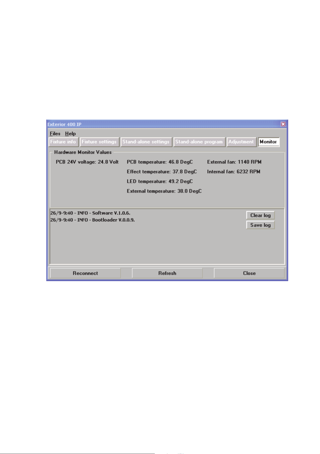
Fixture readouts in MUM
Various types of data can be displayed by connecting a PC as described in "Connecting a PC with MUM" on
page 23 and clicking on the Monitor button:
PCB 24V Voltage displays the current voltage in the 24 volt circuits on the main PCB (this data is for service
purposes).
Temperature readouts display the current main PCB temperature, current effects temperature, the current
temperature on the LED circuit board that gives the highest reading, and the current ambient temperature.
Fan readouts display the current internal and external cooling fan speeds in RPM (revolutions per minute).
Software installation
It may be necessary to upload new software (i.e. firmware) to an Exterior 400 Image Projector fixture if you
believe that the product has a software-related fault or if you want to update to a newer version. Software
updates are available from the Martin website (http://www.martin.com) and can be installed via the DMX
data link with the following items:
• The Martin Uploader application, version 5.0 or later, downloadable free of charge from the Support area
of the Martin website.
• The fixture’s main CPU software update file, downloadable free of charge from the Support area of the
Martin website (this file can be downloaded automatically from within the Martin Uploader application)
Figure 20: Fixture Monitor data
Service and maintenance 35
• A Martin DABS 1™ PC/fixture hardware interface box (supplied in a package with the Martin MUM™
application) and a Windows PC.
Installing software
1. Connect the uploader hardware to a Exterior 400 Image Projector fixture’s data input connector. The
software will be uploaded to that fixture and all fixtures of the same type that are powered on and
connected via the DMX link.
2. Upload the fixture software as described in the uploader’s help file or user documentation.
3. Disconnect the uploader hardware and reconnect the fixture to the DMX link.
4. Cycle power off and on. Check that the fixture resets correctly and behaves normally. If it does not, cycle
power off and on again and check that the fixture now resets correctly and behaves normally. If the
problem persists, contact Martin for assistance.
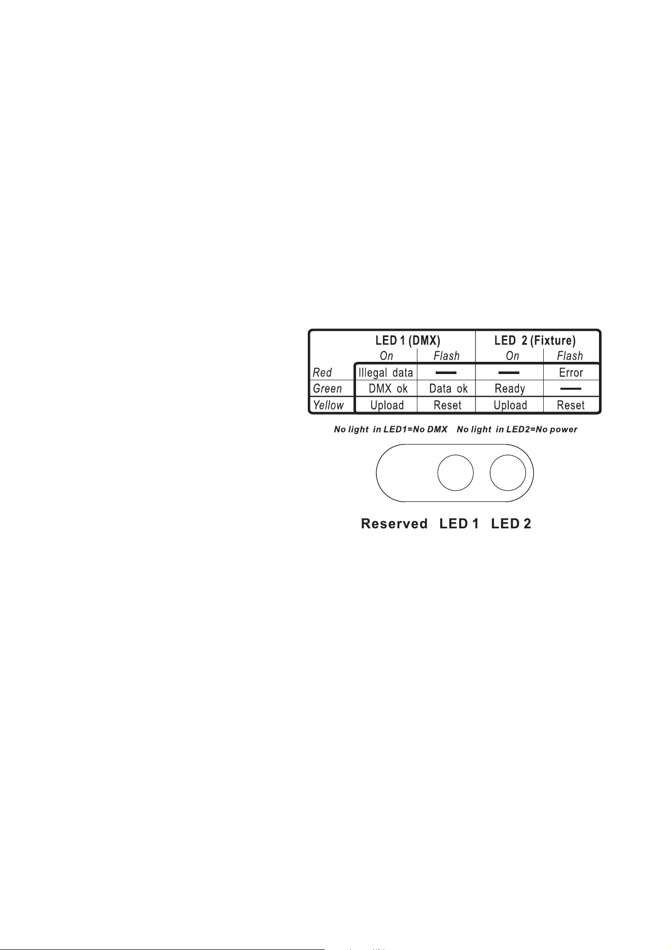
Status indicator LEDs
Two LEDs on the rear cover give information about fixture status.
LED 1 (DMX / data status)
• Lights steady red if the fixture
receives data it cannot recognize.
• Lights steady green when the
fixture is successfully receiving a
DMX signal.
• Flashes green when the fixture is
successfully receiving a data
signal (e.g. RDM).
• Lights steady yellow during a
software upload.
• Flashes yellow while the fixture is
resetting.
LED 2 (Fixture status)
• Flashes red if an error occurs that
requires service intervention.
• Lights steady green when the
fixture is ready for operation.
• Lights steady yellow during a
software upload.
• Flashes yellow while the fixture is resetting.
• Does not light at all if power is not applied to the fixture.
Adjustment
The Adjustment window in MUM is for use by service technicians only. Do not use any commands in this
window unless specifically instructed to do so by Martin™ Service personnel. If you alter the factory
settings, there is a risk that you will cause unsatisfactory performance.
Figure 21: Status indicator LEDs
36 Exterior 400 Image Projector user manual
DMX protocol
Channel DMX Value Percent Function
Fade type
Default
value
1
0 - 19
20 - 49
50 - 64
65 - 69
70 - 84
85 - 89
90 - 104
105 - 109
110 - 124
125 - 129
130 - 144
145 - 149
150 - 164
165 - 169
170 - 184
185 - 189
190 - 204
205 - 209
210 - 224
225 - 229
230 - 244
245 - 255
0 - 19
20 - 49
50 - 64
65 - 69
70 - 84
85 - 89
90 - 104
105 - 109
110 - 124
125 - 129
130 - 144
145 - 149
150 - 164
165 - 169
170 - 184
185 - 189
190 - 204
205 - 209
210 - 224
225 - 229
230 - 244
245 - 255
Electronic shutter effect, strobe (snap)
Shutter closed
Shutter open
Strobe 1, fast → slow
Shutter Open
Strobe 2, fast → slow - Opening Pulse
Shutter Open
Strobe 3, fast → slow - Closing Pulse
Shutter Open
Strobe 4, fast → slow - Random Strobe
Shutter Open
Strobe 5, fast → slow - Random Opening Pulse
Shutter Open
Strobe 6, fast → slow - Random Closing Pulse
Shutter Open
Strobe 7, fast → slow - Burst Pulse
Shutter Open
Strobe 8, fast → slow - Random Burst Pulse
Shutter Open
Strobe 9, fast → slow - Electronic Sinewave
Shutter Open
Strobe 10, fast → slow - Electronic Burst
Shutter Open
Snap 20
2
0 - 255 0 - 100
Intensity (fade)
Zero → full
Fade 0
3
0
1-15
16
17 - 31
32
33 - 47
48
49 - 63
64
65 - 79
80
81 - 95
96
97 - 111
112
113 - 127
128
129 - 143
144
145 - 148
149 - 152
153 - 156
157 - 160
161 - 164
165 - 168
169 - 172
173 - 176
177 - 180
181 - 203
204 - 207
208 - 230
231 - 242
243 - 244
245 - 255
0
0 - 6
6
7 - 12
13
13 - 18
19
19 - 25
25
25 - 31
31
32 - 37
38
38 - 44
44
44 - 50
50
51 - 56
56
57 - 58
59 - 60
60 - 61
62 - 63
63 - 64
65 - 66
66 - 67
68 - 69
69 - 71
71 - 79
80
81 - 90
91 - 94
95
96 - 100
Color selection
Continuously scrolling color wheel positions
Open (white)
Open →
Color 1
Color 1
Color 1 → Color 2
Color 2
Color 2 → Color 3
Color 3
Color 3 → Color 4
Color 4
Color 4 →
Color 5
Color 5
Color 5 →
Color 6
Color 6
Color 6 →
Color 7
Color 7
Color 7 →
Color 8
Color 8
Color 8 →
Open
Open
Stepped scroll (indexed) color wheel positions
Color 8
Color 7
Color 6
Color 5
Color 4
Color 3
Color 2
Color 1
Open
Continuous color wheel rotation
CW, fast → slow
Color wheel stop
CCW, slow → fast
Random color chase
Fast
Medium
Slow
Fade 0
Table 2: DMX Protocol
DMX protocol 37
4
0 - 3
4 - 7
8 - 11
12 - 15
16 - 19
20 - 23
24 - 27
28 - 31
32 - 35
36 - 39
40 - 43
44 - 47
48 - 51
52 - 55
56 - 66
67 - 77
78 - 88
89 - 99
100 - 110
111 - 121
122 - 132
133 - 143
144 - 154
155 - 165
166 - 176
177 - 187
188 - 219
220 - 255
0 - 1
2 - 3
3 - 4
5 - 6
6 - 7
8 - 9
9 - 11
11 - 12
13 - 14
14 - 15
16 - 17
17 - 18
19 - 20
20 - 22
22 - 26
26 - 30
31 - 35
35 - 39
39 - 43
44 - 47
48 - 52
52 - 56
56 - 60
61 - 65
65 - 69
69 - 73
74 - 85
85 - 100
Rotating gobo selection and shake
Indexed static gobo (set indexed gobo angle on channel 5)
Open
Gobo 1
Gobo 2
Gobo 3
Gobo 4
Gobo 5
Gobo 6
Rotation (set gobo rotation speed on channel 5)
Open
Gobo 1
Gobo 2
Gobo 3
Gobo 4
Gobo 5
Gobo 6
Indexed gobo shake (set indexed gobo angle on channel 5)
Gobo 1 shake, slow → fast
Gobo 2 shake, slow → fast
Gobo 3 shake, slow → fast
Gobo 4 shake, slow → fast
Gobo 5 shake, slow → fast
Gobo 6 shake, slow → fast
Rotating gobo shake (set gobo rotation speed on channel 5)
Gobo 6 shake, slow → fast
Gobo 5 shake, slow → fast
Gobo 4 shake, slow → fast
Gobo 3 shake, slow → fast
Gobo 2 shake, slow → fast
Gobo 1 shake, slow → fast
Continuous gobo wheel scroll (set gobo rotation speed on
channel 5)
CW fast → slow
CCW slow → fast
Snap 0
5
0 - 255
0 - 125
126 - 128
129 - 255
0 - 100
0 - 48
49 - 50
51 - 100
Gobo indexing and rotation (select gobo on channel 4)
Indexed position
0 - 395°
Continuous rotation direction and speed
CW, fast → slow
No rotation
CCW, slow → fast
Fade 128
6
0 - 255 0 - 100 Gobo rotation, fine
Fade 128
7
0-199
200-215
216-229
230-243
244-249
250-255
0 - 77
78 - 84
85 - 89
90 - 94
95 - 97
98 - 100
Iris
Open → closed
Closed
Opening pulse, Fast → Slow
Closing pulse, fast → slow
Random opening pulse, fast → slow
Random closing pulse, fast → slow
Fade 0
8
0 - 255 0 - 100
Focus
Infinity → near
Fade 128
9
0 - 9
10 - 14
15 - 19
20 - 24
25 - 29
30 - 34
35 - 39
40 - 44
45 - 49
50 - 54
55 - 59
60 - 64
65 - 69
70 - 74
75 - 255
0 - 1
2 - 3
4 - 5
6 - 7
8 - 9
10 - 11
12 - 13
14 - 15
16 - 17
18 - 19
20 - 21
22 - 23
24 - 25
26 - 27
28 - 100
Fixture control settings
No function
Reset entire fixture
No function
Dimmer curve = Optically linear*
No function
Dimmer curve = Square law*
No function
Dimmer curve = Inverse square law*
No function
Dimmer curve = S-curve*
No function
Calibrated output*
No function
Raw output (maximum possible, non-calibrated)*
No function
*Menu override – setting not affected by power off/on
Snap 0
Channel DMX Value Percent Function
Fade type
Default
value
Table 2: DMX Protocol
38 Exterior 400 Image Projector user manual
Troubleshooting
Problem Probable cause(s) Remedy
Fixture is completely dead.
No power to fixture. Check power and connections.
Internal fuse blown or internal fault.
Isolate fixture from power. Have fixture serviced by
Martin authorized service technician.
One or more fixtures responds
incorrectly to control or does not
respond at all.
Fault on DMX link.
Inspect connections and cables. Correct poor
connections. Repair or replace damaged cables.
Incorrect DMX addressing. Check fixtures’ DMX addresses.
Fixture defective.
Have faulty fixture serviced by Martin service
technician.
Other device on DMX link defective.
Bypass devices on DMX link until the faulty device
has been identified.
Have faulty device tested and serviced by Martin
authorized service technician.
LEDs cut out intermittently. Fixture is too hot.
Ensure free airflow around fixture.
Clean fixture.
Check that ambient temperature does not exceed
maximum permitted level.
Have fixture serviced by Martin authorized service
technician.
Different fixtures give uneven
light output intensity.
One or more fixtures set to Raw
(uncalibrated) output.
Set all fixtures to Calibrated output.
Table 3: Troubleshooting

Specifications 39
Specifications
Physical
Medium and Wide-angle models
Length . . . . . . . . . . . . . . . . . . . . . . . . . . . . . . . . . . . . . . . . . . . . . . 365 mm (14.4 in.) including cable gland
Width . . . . . . . . . . . . . . . . . . . . . . . . . . . . . . . . . . . . . . . . . . . . . 307 mm (12.1 in.) including mounting yoke
Height . . . . . . . . . . . . . . . . . . . . . . . . . . . . . . . . . . . . . . . . . . . . 421 mm (16.6 in.) including mounting yoke
Weight . . . . . . . . . . . . . . . . . . . . . . . . . . . . . . . . . . . . . . . . . . . . . . . . . . . . . . . . . . . . . . . . . 14 kg (30.9 lbs.)
Narrow-angle (long barrel) models
Length . . . . . . . . . . . . . . . . . . . . . . . . . . . . . . . . . . . . . . . . . . . . . . 425 mm (16.7 in.) including cable gland
Width . . . . . . . . . . . . . . . . . . . . . . . . . . . . . . . . . . . . . . . . . . . . . 307 mm (12.1 in.) including mounting yoke
Height . . . . . . . . . . . . . . . . . . . . . . . . . . . . . . . . . . . . . . . . . . . . 421 mm (16.6 in.) including mounting yoke
Weight . . . . . . . . . . . . . . . . . . . . . . . . . . . . . . . . . . . . . . . . . . . . . . . . . . . . . . . . . . . . . . . . . 15 kg (33.1 lbs.)
Dynamic Effects
Color wheel . . . . . . . . . . . . . . . . . . .Slots for 8 interchangeable dichroic filters + open, full and split colors,
continuous rotation, random color
Rotating gobo wheel . . . . . . . . . . . . Slots for 6 interchangeable gobos + open, indexing, continuous gobo
rotation & scrolling, shake
Motorized iris . . . . . . . . . . . . . . . . . . . . . . . . . . . . . . . . . . . . . . . . . . . . . . . . . . . . . . 0 - 100%, pulse effects
Motorized focus . . . . . . . . . . . . . . . . . . . . . . . . . . . . . . . . . . . . . . . . . . . . . . . Approx. 2 m (6.6 ft.) to infinity
Electronic dimming . . . . . . . . . . . . . . . . . . . . . . . . . . . . . . . . . . . . . . . . . . . . 0 - 100% continuous dimming
Electronic 'shutter' effect . . . . . . . . . . . . . . . . . . . .Strobe, pulse and sinewave intensity modulation effects
Pre-programmed effects . . . . . . . . . . . . . . . . . . . . . . . Varied macro effects available in stand-alone mode
Optics
Light source . . . . . . . . . . . . . . . . . . . . . . . . . . . . . . . . . . . . . . . . . . . . . . . 7 x Luminus CBT-90 (50 W) LEDs
White LED . . . . . . . . . . . . . . . . . . . . . . . . . . . . . . . . . . . . . . . . . . . . . . . . . . . . . . . . . . . . . . . . . . . . . 6500 K
Minimum LED lifetime . . . . . . . . . . . . . . . . . . . . . . . . . . . . . . . . . 60 000 hours (to >70% luminous output)*
*Manufacturer´s figure obtained under manufacturer´s test conditions
Photometric Data
Luminous flux* . . . . . . . . . . . . . . . . . . . . . . . . . . . . . . . . . . . . . . . . . . . . . . . . . . . . . 7400 lm (with 25° lens)
Cutoff angles* . . . . . . . . . . . . . . . . . . . . . . . . . Narrow models 15°, Medium models 25°, Wide models 40°
*Preliminary data – see www.martin.com for updated photometric data
Control and Programming
C
ontrol options. . . . . . . . . . . . . . . . . . . . . . . . . . . . . . . . . . DMX, stand-alone, synchronized (master/client)
Device management . . . . . . . . . . . . . . . . . . . . . . . . . . . . . . . . . . . . . . . . . . . . . . . . . . . . . . . . . . . . . . .RDM
DMX channels . . . . . . . . . . . . . . . . . . . . . . . . . . . . . . . . . . . . . . . . . . . . . . . . . . . . . . . . . . . . . . . . . . . . . . .9
DMX address setting . . . . . . . . . . . . . PC with Martin MUM™ software and DABS 1™ interface box, RDM
Stand-alone trigger options . . . . . . . . . . . . . . . . . . . . . . . . . . . . . . . . . . . . . . . . . . . . . . . . . . . Internal timer
Stand-alone (single fixture and/or synchronized) programming . . . . . . . . . . . . PC with MUM software and
DABS 1 interface box
Stand-alone program capacity. . . . . . . . . . . . . . . . . . . . . . . . . . . . . . . . . . . . . . . . . . . . . .Up to 100 scenes
DMX compliance . . . . . . . . . . . . . . . . . . . . . . . . . . . . . . . . . . . . . . . . . . . .ANSI E1.11 (USITT DMX 512-A)
RDM compliance . . . . . . . . . . . . . . . . . . . . . . . . . . . . . . . . . . . . . . . . . . . . . . . . . . . . . . . . . . . . ANSI E1.20
Receiver. . . . . . . . . . . . . . . . . . . . . . . . . . . . . . . . . . . . . . . . . . . . . . . . . . . . . . . . . . . . . . . . . . . . . . .RS-485
Firmware update . . . . . . . . . . . . . . . . . . . . . . . . . . . . . . . . . . . . . . . . . . . . . . . . .Serial upload via DMX link
Construction
Color . . . . . . . . . . . . . . . . . . . . . . . . . . . . . . . . . . . . .Clear anodized, white, custom colors to special order
Housing . . . . . . . . . . . . . . . . . . . . . . . . . . . . . . . . . . . . . . . . . . . . . . . . . . . . . . . . . . . . . Anodized aluminum
Mounting yoke . . . . . . . . . . . . . . . . . . . . . . . . . . . . . . . . . . . . . . . . . . . . .8 mm (0.3 in.) anodized aluminum
Front glass . . . . . . . . . . . . . . . . . . . . . . . . . . . . . . . . . . . . . . . . . . . . . . 6 mm (0.2 in.) anti-reflection coated
Protection rating. . . . . . . . . . . . . . . . . . . . . . . . . . . . . . . . . . . . . . . . . . . . . . . . . . . . . . . . . . . . . . . . . . . IP65
Effective projected area (EPA) . . . . . . . . . . . . . . . . . . . . . . . . . . . . . . . . . . . . . . . . . . . . . . . . . . . . . 0.15 m
2

Gobos
Outside diameter . . . . . . . . . . . . . . . . . . . . . . . . . . . . . . . . . . . . . . 27.9 mm (1.1 in.) +0/- 0.3 mm (0.01 in.)
Maximum image diameter . . . . . . . . . . . . . . . . . . . . . . . . . . . . . . . . . . . . . . . . . . . . . . . . . . .23 mm (0.9 in.)
Maximum thickness . . . . . . . . . . . . . . . . . . . . . . . . . . . . . . . . . . . . . . . . . . . . . . . . . . . . . . . 1.8 mm (0.1 in.)
Recommended glass . . . . . . . . . . . . . . . . . High-temperature Borofloat or better with dichroic or enhanced
aluminum coating
Recommended metal. . . . . . . . . . . . . . . . . . . . . . . . . . . . . . . . . . . Aluminum (steel for temporary use only)
Installation
Orientation . . . . . . . . . . . . . . . . . . . . . . . . . . . . . . . . . . . . . . . . . . . . . . . . . . . . . . . . . . . . . . . . . . . . . . . .Any
Vertical aiming . . . . . . . . . . . . . . . . . . . . . . . . . . . . . . . . . . . . . . . . . . . . . . . . . . . . . . . . . . . . . . . . . . . . 330°
Minimum distance to illuminated surfaces . . . . . . . . . . . . . . . . . . . . . . . . . . . . . . . . . . . . . . . 0.5 m (20 ins.)
Connections
Power connection. . . . . . . . . . . . . . . . . . . . . . . . . . . . . . . . . . . . . . . . . . . . . . . . . . . 1.8 m (5.9 ft.) cable tail
Power cable entry . . . . . . . . . . . . . . . . . . . . . . . . . . . . . . . . . . . . . . . . . . . . . . . . . . . . . . . IP68 cable gland
Data connection. . . . . . . . . . . . . . . . . . . . . . . . . . . . . . . . .1.8 m (5.9 ft.) combined input + output cable tail
Data cable entry. . . . . . . . . . . . . . . . . . . . . . . . . . . . . . . . . . . . . . . . . . . . . . . . . . . . . . . . . IP68 cable gland
Electrical
AC power . . . . . . . . . . . . . . . . . . . . . . . . . . . . . . . . . . . . . . . . . . . . . . . . . . . . 100-240 V nominal, 50/60 Hz
Power consumption, zero output, all effects static . . . . . . . . . . . . . . . . . . . . . . . . . . . . . . . . . . . . . . . . .13 W
Power supply unit. . . . . . . . . . . . . . . . . . . . . . . . . . . . . . . . . . . . . . . .Integrated, auto-sensing multi-voltage
Typical Power and Current
100 V, 50 Hz. . . . . . . . . . . . . . . . . . . . . . . . . . . . . . . . . . . . . . . . . . . . . . . . . . . . . . . 422 W, 4.2 A, PF 0.995
100 V, 60 Hz. . . . . . . . . . . . . . . . . . . . . . . . . . . . . . . . . . . . . . . . . . . . . . . . . . . . . . . 418 W, 4.2 A, PF 0.995
110 V, 60 Hz. . . . . . . . . . . . . . . . . . . . . . . . . . . . . . . . . . . . . . . . . . . . . . . . . . . . . . . 417 W, 3.8 A, PF 0.994
120 V, 60 Hz. . . . . . . . . . . . . . . . . . . . . . . . . . . . . . . . . . . . . . . . . . . . . . . . . . . . . . . 415 W, 3.5 A, PF 0.992
208 V, 60 Hz. . . . . . . . . . . . . . . . . . . . . . . . . . . . . . . . . . . . . . . . . . . . . . . . . . . . . . . 409 W, 2.1 A, PF 0.957
230 V, 50 Hz. . . . . . . . . . . . . . . . . . . . . . . . . . . . . . . . . . . . . . . . . . . . . . . . . . . . . . . 409 W, 1.9 A, PF 0.960
240 V, 50 Hz. . . . . . . . . . . . . . . . . . . . . . . . . . . . . . . . . . . . . . . . . . . . . . . . . . . . . . . 408 W, 1.8 A, PF 0.954
Measurements made at nominal voltage with all LEDs at full intensity. Allow for a deviation of +/- 10%.
Thermal
Cooling. . . . . . . . . . . . . . . . . . . . . . . . . . . . . . . . . . . . . . . . . . . . . . . . . . . . . . . . . . . . . . . . . . . . . Convection
Maximum ambient temperature (Ta max.) . . . . . . . . . . . . . . . . . . . . . . . . . . . . . . . . . . . . . . . 45° C (113° F)
Minimum ambient temperature (Ta min.)* . . . . . . . . . . . . . . . . . . . . . . . . . . . . . . . . . . . . . . -30° C (-22° F)*
Maximum surface temperature, steady state, Ta=40° C . . . . . . . . . . . . . . . . . . . . . . . . . . . . 65° C (149° F)
Total heat dissipation (calculated, +/- 10%) . . . . . . . . . . . . . . . . . . . . . . . . . . . . . . . . . . . . . . . 1440 BTU/hr.
*Power must remain applied to the fixture at all times if the ambient temperature falls below 0° C (32° F)
Approvals
EU safety . . . . . . . . . . . . . . . . . . . . . . . . . . . . . . . . . . . . . . .EN 60598-2-17
EU EMC. . . . . . . . . . EN 55015, EN 61000-3-2, EN 61000-3-3, EN 61547
US safety (US model) . . . . . . . . . . . . . . . . . . . . . . . . . . UL 1573, UL 1598
US EMC (US model) . . . . . . . . . . . . . . . . . . . . . . . . . FCC Part 15 Class A
Canadian safety (US model) . . CSA C.22.2 No. 166, CSA C.22.2 No. 250
Included Items
Power and data cable tails (pre-installed)
Adjustable mounting yoke
Washers for use with mounting fasteners
User manual
Color filters (pre-installed)
Blue B04-6 . . . . . . . . . . . . . . . . . . . . . . . . . . . . . . . . . . . . . . . . . . . . . . . . . . . . . . . . . . . . . . . P/N 62327198
Orange B09-6 . . . . . . . . . . . . . . . . . . . . . . . . . . . . . . . . . . . . . . . . . . . . . . . . . . . . . . . . . . . . P/N 62327201
Gobos (pre-installed)
Tight Stripple . . . . . . . . . . . . . . . . . . . . . . . . . . . . . . . . . . . . . . . . . . . . . . . . . . . . . . . . . . . . . P/N 43072011
Dots Breakup Small . . . . . . . . . . . . . . . . . . . . . . . . . . . . . . . . . . . . . . . . . . . . . . . . . . . . . . . . P/N 43072009
All necessary goboholders with springs (six in total) are included

Accessories
Safety eyebolt . . . . . . . . . . . . . . . . . . . . . . . . . . . . . . . . . . . . . . . . . . . . . . . . . . . . . . . . . . . . P/N 91611239
Safety wire, safe working load 50 kg (110.2 lbs.). . . . . . . . . . . . . . . . . . . . . . . . . . . . . . . . . . P/N 91604003
3-pin male XLR connector, cable-type, IP65-rated . . . . . . . . . . . . . . . . . . . . . . . . . . . . . . . . P/N 91611306
3-pin female XLR connector, cable-type, IP65-rated . . . . . . . . . . . . . . . . . . . . . . . . . . . . . . . P/N 91611307
Example color filters (glued in holders)
Light green B08-0 . . . . . . . . . . . . . . . . . . . . . . . . . . . . . . . . . . . . . . . . . . . . . . . . . . . . . . . . . P/N 62327199
Light yellow B03-0 . . . . . . . . . . . . . . . . . . . . . . . . . . . . . . . . . . . . . . . . . . . . . . . . . . . . . . . . . P/N 62327200
Pink B11-2 . . . . . . . . . . . . . . . . . . . . . . . . . . . . . . . . . . . . . . . . . . . . . . . . . . . . . . . . . . . . . . . P/N 62327196
Magenta B12 . . . . . . . . . . . . . . . . . . . . . . . . . . . . . . . . . . . . . . . . . . . . . . . . . . . . . . . . . . . . . P/N 62327180
Congo B13-1 (“Fluorescent”) . . . . . . . . . . . . . . . . . . . . . . . . . . . . . . . . . . . . . . . . . . . . . . . . . P/N 62327197
Deep red B4-17 . . . . . . . . . . . . . . . . . . . . . . . . . . . . . . . . . . . . . . . . . . . . . . . . . . . . . . . . . . . P/N 62327179
These are just examples of the range of color filters available from Martin™
Example gobos
Jessica Rose (aluminum, gobo only). . . . . . . . . . . . . . . . . . . . . . . . . . . . . . . . . . . . . . . . . . . P/N 43070098
Rotation Spikes (glass, gobo only) . . . . . . . . . . . . . . . . . . . . . . . . . . . . . . . . . . . . . . . . . . . . P/N 43072008
Organic 6 (glass, gobo only) . . . . . . . . . . . . . . . . . . . . . . . . . . . . . . . . . . . . . . . . . . . . . . . . . P/N 43072010
Blue Ripple (glass, gobo glued in holder) . . . . . . . . . . . . . . . . . . . . . . . . . . . . . . . . . . . . . . . P/N 62400796
These are just examples of the range of gobos available from Martin™
Related Items
Martin MUM™ (Multi-Utility Manager) incl. DABS 1™ interface box & cables. . . . . . . . . . . . P/N 90758090
Martin RDM 5.5 Splitter™ . . . . . . . . . . . . . . . . . . . . . . . . . . . . . . . . . . . . . . . . . . . . . . . . . . . P/N 90758150
Martin M-PC™ Pro (up to 64 DMX universes) incl. USB Duo™ interface box . . . . . . . . . . . P/N 90732010
Martin M-PC™ Basic (up to 8 DMX universes) incl. USB Duo™ interface box . . . . . . . . . . . P/N 90732070
Martin USB Duo™ USB/DMX interface box . . . . . . . . . . . . . . . . . . . . . . . . . . . . . . . . . . . . . P/N 90703010
Ordering Information
Exterior 400 Image Projector™ Narrow, EU model . . . . . . . . . . . . . . . . . . . . . . . . . . . . . . . . P/N 90356500
Exterior 400 Image Projector™ Narrow, US model . . . . . . . . . . . . . . . . . . . . . . . . . . . . . . . . P/N 90356510
Exterior 400 Image Projector™ Medium, EU model . . . . . . . . . . . . . . . . . . . . . . . . . . . . . . . P/N 90507050
Exterior 400 Image Projector™ Medium, US model . . . . . . . . . . . . . . . . . . . . . . . . . . . . . . . P/N 90507060
Exterior 400 Image Projector™ Wide, EU model . . . . . . . . . . . . . . . . . . . . . . . . . . . . . . . . . P/N 90356540
Exterior 400 Image Projector™ Wide, US model . . . . . . . . . . . . . . . . . . . . . . . . . . . . . . . . . P/N 90356550
Custom colors available by special order – please contact your Martin™ supplier for details
Specifications subject to change without notice.
See Product Support page on www.martin.com for latest specifications including photometric data.


www.martin.com • Olof Palmes Allé 18 • 8200 Aarhus N • Denmark
Tel: +45 8740 0000 • Fax +45 8740 0010
